Scheme 1: (a) Preparation of thiophene Grignard monomer and synthesis of P3HT by Kumada catalyst transfer polymerization. (b) Schematic repre-sentation for the flow setup using nickel complex 3 and (c) Ni(dppp)Cl2.
reactive Grignard monomer has been consumed. Controlled
polymerization and high molecular weights have been demon-
strated by many research groups with variations to this general
method [6-9].
Significant quantities of materials are required for the optimiz-
ation of large-area roll-to-roll printed organic solar cells [3,10].
While some of the organic semiconducting materials can be
obtained commercially an a hundreds-of-grams scale, it is
important to explore methods for scaled-up production in order
to gain access to in-house materials at reasonable costs and lead
times. In addition, batch-to-batch variations in the molecular
weight distribution have been observed in commercial polymer
samples, leading to differences in material deposition and film
quality. This will almost certainly create problems with the
performance consistency of large-area roll-to-roll printed
devices. To this end, we have started to examine some key reac-
tions in the synthesis of organic electronic materials using
continuous-flow processing [11-13].
Continuous-flow synthesis methods offer several advantages
over traditional batch methods [14-18]. The scale-up of reac-
tions is not only straightforward in continuous processing, but
there are also benefits in high reaction reproducibility through
Beilstein J. Org. Chem. 2013, 9, 1492–1500.
1494
Table 1: Flow polymerizations initiated with o-tolyl–nickel complex 3.a
aPolyfluoroalkoxy (PFA) tube reactor volume = 30 mL and heated at 100 °C. bMolecular weight values obtained by GPC in toluene calibrated againstpolystyrene standards with refractive index detection. cFlow rates were readjusted after the injection of reagents to afford a residence time of 53 min.dData obtained after Soxhlet extraction with methanol and petroleum spirits 40–60 °C.
accurate parameter control, superior heating and mixing of
reagents, boosting reaction rates, and safe handling of reactive
intermediates. Using a commercial continuous-flow tube reactor
[19], we have already demonstrated multigram synthesis of
fullerene derivatives by cycloaddition reactions [11] as well as
rapid conjugated-polymer synthesis using Suzuki–Miyaura and
Stille coupling [12]. In this study, the continuous-flow syn-
thesis of P3HT is examined. Distinct from a recent report of
P3HT synthesis in a droplet-based microreactor [20], develop-
ment of the flow synthesis is described in detail and controlled
polymerization of P3HT, both in terms of molecular weight and
regioregularity, has been achieved in this work. In particular,
the feed ratio of catalyst to monomer was accurately controlled
giving polymers with molecular weights ranging from 5 to
40 kg/mol as desired. In addition, BHJ devices prepared using
commercial, batch and flow-synthesized P3HT gave compa-
rable performance.
Results and DiscussionThe most widely used synthetic route to regioregular P3HT is
the Kumada catalyst transfer polycondensation (KCTP) devel-
oped by the McCullough group [6] and the Yokozawa group
[7]. In a representative experiment for the preparation of P3HT,
the thiophene Grignard monomer 2 is prepared from the magne-
sium exchange reaction of an alkyl Grignard reagent and 2,5-
dibromo-3-hexylthiophene (1, Scheme 1a). It should be noted
here that a mixture of Grignard monomers 2a and 2b is
produced in this step, typically in a ratio of 75:25. Only 2a
participates in the polymerization step on addition of the cata-
lyst, Ni(dppp)Cl2, as a solid (Scheme 1a) [6]. As KCTP is a
quasi-living polymerization, the product molecular weight can
be controlled by adjusting the monomer-to-catalyst ratio [21].
At the start of this study, the aim was to transfer conventional
batch reaction conditions for P3HT synthesis to continuous-
flow processing. The polymerization step in flow was exam-
ined first with the thiophene Grignard monomer prepared in
batch. Good solubility and solvent compatibility in the polymer-
ization are essential factors to be evaluated for the translation
into flow methods. The accurate addition of Ni catalyst to the
thiophene Grignard monomer results in the desired catalyst-to-
monomer ratio and molecular-weight control. An initial attempt
was made to prepare a solution of the commonly used
Ni(dppp)Cl2 catalyst in tetrahydrofuran (THF) which was then
added to a solution of the thiophene Grignard monomer. Two
problems immediately arose from this early experiment. The
Ni(dppp)Cl2 catalyst only has modest solubility in THF at room
temperature. This limited the concentration of the polymeriza-
tion reaction. The second more serious problem is the dissocia-
tion of the catalyst species in THF solution. There was a visible
color change in the Ni(dppp)Cl2/THF solution from orange to
colorless over a period of several minutes. The dissociation of
the catalyst species was accompanied by a decrease in catalyst
activity leading to low polymer formation. To solve this
problem, we were inspired by the work of a number of research
groups, in which polymerization was externally initiated from
an active tolyl-functionalized nickel complex 3 (Scheme 1a)
[8,9,22]. The tolyl–nickel species 3 is soluble and shows good
stability in THF in an inert environment. Further, polymers
initiated with this complex showed lower defect levels [23,24].
After successfully experimenting with this catalyst in batch
conditions, the reagent was applied in flow processing for the
synthesis of P3HT (Scheme 1b).
The thiophene Grignard reagent 2 was prepared by traditional
batch chemistry and the conversion and regioisomeric ratio
were assessed in quenching experiments (Scheme 1a, ratio 2a to
2b 77:23; see Figure S2 in Supporting Information File 1 for1H NMR data). The Ni catalyst 3 was delivered to a T-piece via
an injection loop and mixed with a stream of Grignard 2
(Scheme 1b) [25]. The mixture was directed to a preheated coil
reactor (polyfluoroalkoxy, PFA) at 100 °C with a retention time
of 30 min. The polymer solution was then quenched in
methanolic HCl (2 M) and the precipitated product was
collected. The monomer-to-initiator ratio was adjusted through
the variation of flow rates and reagent concentrations (Table 1).
Beilstein J. Org. Chem. 2013, 9, 1492–1500.
1495
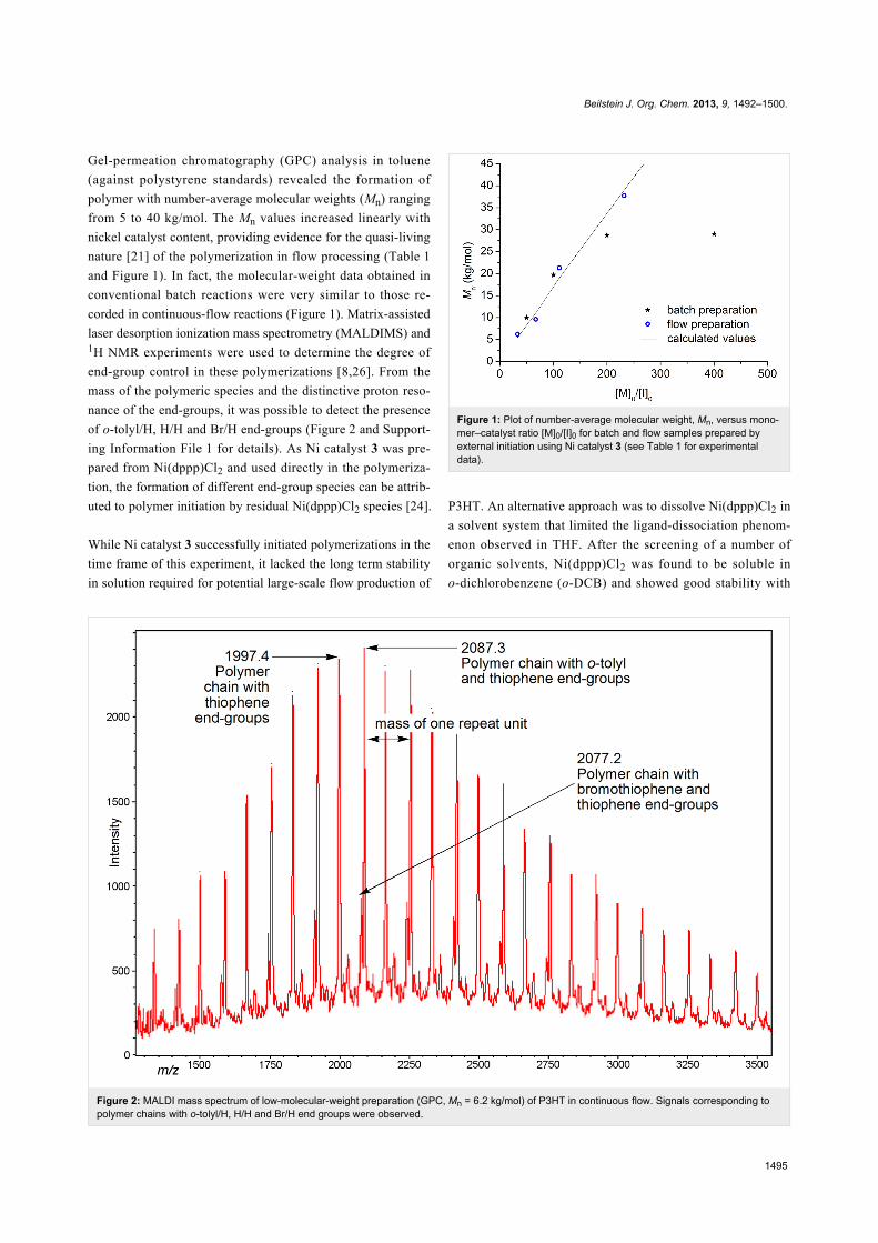
Figure 2: MALDI mass spectrum of low-molecular-weight preparation (GPC, Mn = 6.2 kg/mol) of P3HT in continuous flow. Signals corresponding topolymer chains with o-tolyl/H, H/H and Br/H end groups were observed.
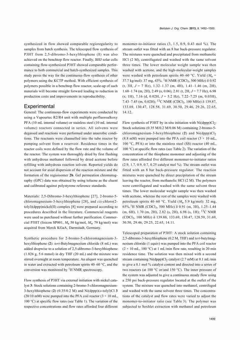
Gel-permeation chromatography (GPC) analysis in toluene
(against polystyrene standards) revealed the formation of
polymer with number-average molecular weights (Mn) ranging
from 5 to 40 kg/mol. The Mn values increased linearly with
nickel catalyst content, providing evidence for the quasi-living
nature [21] of the polymerization in flow processing (Table 1
and Figure 1). In fact, the molecular-weight data obtained in
conventional batch reactions were very similar to those re-
corded in continuous-flow reactions (Figure 1). Matrix-assisted
laser desorption ionization mass spectrometry (MALDIMS) and1H NMR experiments were used to determine the degree of
end-group control in these polymerizations [8,26]. From the
mass of the polymeric species and the distinctive proton reso-
nance of the end-groups, it was possible to detect the presence
of o-tolyl/H, H/H and Br/H end-groups (Figure 2 and Support-
ing Information File 1 for details). As Ni catalyst 3 was pre-
pared from Ni(dppp)Cl2 and used directly in the polymeriza-
tion, the formation of different end-group species can be attrib-
uted to polymer initiation by residual Ni(dppp)Cl2 species [24].
While Ni catalyst 3 successfully initiated polymerizations in the
time frame of this experiment, it lacked the long term stability
in solution required for potential large-scale flow production of
Figure 1: Plot of number-average molecular weight, Mn, versus mono-mer–catalyst ratio [M]0/[I]0 for batch and flow samples prepared byexternal initiation using Ni catalyst 3 (see Table 1 for experimentaldata).
P3HT. An alternative approach was to dissolve Ni(dppp)Cl2 in
a solvent system that limited the ligand-dissociation phenom-
enon observed in THF. After the screening of a number of
organic solvents, Ni(dppp)Cl2 was found to be soluble in
o-dichlorobenzene (o-DCB) and showed good stability with
Beilstein J. Org. Chem. 2013, 9, 1492–1500.
1496
Table 2: Data for flow polymerization using Ni(dppp)Cl2 catalyst dissolved in o-DCB.a
aStainless-steel tube reactor volume = 40 mL for entries 1 and 2; PFA tube reactor volume = 30 mL for entries 3 to 5. Reactors heated to 100 °C.bFlow rate was readjusted after injection of reagents to afford 50 min residence time. cAfter Soxhlet extraction with methanol and petroleum spirits40–60 °C.
catalytic activity maintained over several days under normal
atmospheric conditions. It is interesting to note that o-DCB did
not adversely affect the polymerization in batch reactions
despite the possibility that the aryl chloride solvent might
participate in the Kumada reaction. Apparently, the reactivity of
aryl chloride is significantly lower than that of aryl bromide
under these reaction conditions.
With the catalytic activity of Ni(dppp)Cl2 in o-DCB confirmed
in batch reactions, continuous-flow processing was investigated
(Scheme 1c, see Supporting Information File 1 for batch syn-
thesis procedures). The preparation of various molecular
weights was achieved by fine-tuning of the monomer-to-cata-
lyst ratio [M]0/[I]0, by varying the concentration of the Grig-
nard reagent 2 and the flow rates of the monomer and catalyst.
The results for the flow polymerizations are summarized in
Table 2, and Figure 3 shows the correlation between [M]0/[I]0
and molecular weight and comparison with batch experiments.
The polymerization in flow compared well with the theoretical
molecular weights up to 20 kg/mol. High-molecular-weight
P3HT (Mp 66.7 kg/mol) was obtained in continuous flow and
this was achieved in shorter reaction time compared to the batch
reaction (Table 2, entry 5). The deviation from the calculated
values at high molecular weights in flow processing and in
batch reactions with short reaction time (30 min) indicated that
longer reaction times were required (Figure 3). In batch reac-
tion with long polymerization times (1 h), the measured molec-
ular-weight values matched with the calculated numbers from
the [M]0/[I]0 ratio (Figure 3). As our current flow setup is
limited by the size of the coil reactors, we anticipate that larger
coil reactor volumes would ensure high-throughput production
of high-molecular-weight P3HT in continuous flow.
In our studies, stainless-steel tube reactors were also examined
for the synthesis of P3HT. In comparison to polyfluoroalkoxy
(PFA) tube reactors, stainless-steel tube reactors offer the
advantage of low gas permeability. Satisfactory results were
Figure 3: Plot of number-average molecular weight, Mn, versus mono-mer–catalyst ratio [M]0/[I]0 for batch and flow samples prepared withNi(dppp)Cl2 catalyst dissolved in o-DCB (see Table 2 for experimentaldata).
achieved for relatively low degrees of polymerization in the
stainless-steel reactors (Table 2, entries 1 and 2). Interestingly,
higher molecular weights could only be achieved in the PFA
reactors (Table 2, entries 3–5). This suggests that the nickel-
catalyzed polymerization is incompatible with the stainless-steel
reactor and we speculate that the nickel content in stainless steel
may be the cause of the incompatibility especially at the
elevated reaction temperatures used.
To demonstrate the flow synthesis of P3HT from 2,5-dibromo-
3-hexylthiophene (1), the Grignard metathesis step was
performed in the tube reactor followed by the addition of the
Ni(dppp)Cl2 catalyst for the polymerization (Scheme 2). In this
telescoped process, the thiophene Grignard compounds 2a and
2b were formed in the first coil and subsequently mixed with
the catalyst stream and fed into the second reactor (Scheme 2).
The two-step reaction was performed under superheated condi-
tions (at 250 psi back pressure) and the reagent flow rates were
adjusted to deliver reasonable reaction times for both reactors.
For the Grignard metathesis step, a stock solution containing
Beilstein J. Org. Chem. 2013, 9, 1492–1500.
1497
Scheme 2: Schematic representation of the telescoped preparation of P3HT in a flow reactor.
Table 3: Data for the telescoped synthesis of P3HT from 2,5-dibromo-3-hexylthiophene (1) in flow.a
aReactor 1 (PFA × 2) volume = 20 mL; reactor 2 (PFA and stainless steel) = 20 mL. bResidence time for the polymerization. cAfter Soxhlet extractionwith methanol and petroleum spirits 40–60 °C. dReaction time was adjusted by slowing down the flow rate after reactor 1.
Figure 4: 1H NMR (CDCl3, 500 MHz) spectra of P3HT samples prepared in (a) flow and (b) batch show comparable regioregularity of approximately95% for both processes. P3HT prepared in flow (Mn = 20 kg/mol) and in batch (Mn = 17 kg/mol) (* designates residual solvent).
both 2,5-dibromo-3-hexylthiophene (1) and the tert-butylmag-
nesium chloride (0.2 M in THF) were allowed to react at 100 °C
with a retention time of 20 min in reactor coil 1.
Ni(dppp)Cl2 catalyst in o-DCB was added to this reaction
stream and the polymerization was heated at 150 °C for 18 min.
Under these conditions, we succeeded in obtaining P3HT with
Mn of 31 kg/mol and polydispersity of 1.5 (Table 3, entry 1).
The regioregularity was estimated to be 95% from the integra-
tion of the α-methylene protons in the 1H NMR spectrum
(Figure 4). The same degree of regioregularity was observed for
a batch sample of similar molecular weight. Additionally, the
variation of the molecular weight was investigated when the
[M]0/[I]0 ratio was varied. As expected, increasing the concen-
tration or the flow rate of the catalyst stock solution, afforded
lower-molecular-weight polymers (Table 3, entries 2 and 3).
Beilstein J. Org. Chem. 2013, 9, 1492–1500.
1498
Table 4: Solar cell data for devices containing various P3HT samples.a
aJsc = short circuit current density; Voc = open circuit voltage; FF = fill factor; PCE = power conversion efficiency; performance shown was the averagefrom 6 pixels with an area of 0.1 cm2. bMerck = Merck lisicon SP001; flow 1 = Table 1, entry 4; flow 2 = Table 2, entry 5; batch 1 = P3HT synthesizedwith catalyst 3; batch 2 = P3HT synthesized with Ni(dppp)Cl2. cThickness of active layer. Measurements were performed in air.
In order to assess the device performance of P3HT synthesized
using flow methods described in this study, bulk heterojunction
(BHJ) solar cells were fabricated and tested. BHJ devices were
fabricated with the following device geometry: ITO/
PEDOT:PSS/P3HT:PC61BM (1:1)/ZnO nanoparticle/Al, where
ITO = indium tin oxide, PEDOT:PSS = poly(3,4-ethylenedioxy-
thiophene):poly(styrenesulfonate) and PC61BM = [6,6]-phenyl-
C61-butyric acid methyl ester (Figure 5a). The P3HT:PC61BM
active layer was deposited by spin coating from chlorobenzene
solution. Device fabrication and characterizations were
performed in air (see Supporting Information File 1 for details).
The current-density–voltage (J–V) curves for the solar-cell
devices prepared from various P3HT samples are shown in
Figure 5b. The device performance parameters for the different
P3HT samples were all rather similar with power conversion
efficiency (PCE) ranging from 2.1 to 2.6% (Table 4). The short
circuit current density (Jsc) parameter showed the largest varia-
tions and this directly correlated with the thickness of the device
active layer (Table 4). Thinner active layers absorbed less of the
incoming irradiation leading to decreased Jsc. It is pleasing to
note that the performance of the commercial P3HT sample
(Merck lisicon SP001) was comparable to that of P3HT from
flow synthesis (Table 4). It should be noted that the lower PCE
of these devices compared with some literature values [1] was
attributed to the fact that all devices were fabricated and
measured in air. Interestingly, P3HT samples with different
end-group variations did not have significant effects on device
performance. These results are extremely encouraging for the
product of device-grade P3HT using continuous-flow methods
with simple benchtop equipment.
ConclusionP3HT has been successfully synthesized in continuous flow by
using a commercially available benchtop flow reactor. After op-
timization of reaction conditions, good molecular-weight
control was achieved by adjusting the monomer-to-catalyst ratio
with variations in reagent concentration and flow rates. This
Figure 5: (a) Schematic diagram of the photovoltaic device geometryand (b) J–V curves of BHJ solar cells with P3HT:PC61BM active layerdeposited by spin coating from chlorobenzene solution. Commercial =Merck P3HT (lisicon SP001); flow 1 = Table 1, entry 4; flow 2 =Table 2, entry 5; batch 1 = P3HT synthesized with catalyst 3; batch 2 =P3HT synthesized with Ni(dppp)Cl2.
methodology enables the controlled synthesis of conjugated
polymers in flow exclusively by the adjustment of the feed of
monomer and initiator into the tube reactor. The major chal-
lenge in this study was to find compatible nickel catalyst
systems for the Kumada polymerization step in flow. Both
o-tolyl–Ni catalyst 3 in THF and Ni(dppp)Cl2 in o-DCB were
highly active in continuous processing conditions, and high-
molecular-weight P3HT was obtained for both catalysts. Apart
from the molecular weight of the polymers, the P3HT samples
Beilstein J. Org. Chem. 2013, 9, 1492–1500.
1499
synthesized in flow showed comparable regioregularity to
samples from batch synthesis. The telescoped flow synthesis of
P3HT from 2,5-dibromo-3-hexylthiophene (1) was also
achieved on the benchtop flow reactor. Finally, BHJ solar cells
8. Senkovskyy, V.; Sommer, M.; Tkachov, R.; Komber, H.; Huck, W. T. S.;Kiriy, A. Macromolecules 2010, 43, 10157. doi:10.1021/ma1024889
9. Bronstein, H. A.; Luscombe, C. K. J. Am. Chem. Soc. 2009, 131,12894. doi:10.1021/ja9054977
10. Yang, J.; Vak, D.; Clark, N.; Subbiah, J.; Wong, W. W. H.; Jones, D. J.;Watkins, S. E.; Wilson, G. Sol. Energy Mater. Sol. Cells 2013, 109, 47.doi:10.1016/j.solmat.2012.10.018
11. Seyler, H.; Wong, W. W. H.; Jones, D. J.; Holmes, A. B. J. Org. Chem.2011, 76, 3551. doi:10.1021/jo2001879
12. Seyler, H.; Jones, D. J.; Holmes, A. B.; Wong, W. W. H.Chem. Commun. 2012, 48, 1598. doi:10.1039/C1CC14315H
13. Seyler, H.; Haid, S.; Kwon, T.-H.; Jones, D. J.; Bäuerle, P.;Holmes, A. B.; Wong, W. W. H. Aust. J. Chem. 2013, 66, 151.doi:10.1071/CH12406
14. Jas, G.; Kirschning, A. Chem.–Eur. J. 2003, 9, 5708.doi:10.1002/chem.200305212
15. Mason, B. P.; Price, K. E.; Steinbacher, J. L.; Bogdan, A. R.;McQuade, D. T. Chem. Rev. 2007, 107, 2300. doi:10.1021/cr050944c
16. Razzaq, T.; Kappe, C. O. Chem.–Asian J. 2010, 5, 1274.doi:10.1002/asia.201000010
17. Geyer, K.; Codée, J. D. C.; Seeberger, P. H. Chem.–Eur. J. 2006, 12,8434. doi:10.1002/chem.200600596
18. Hartman, R. L.; McMullen, J. P.; Jensen, K. F. Angew. Chem., Int. Ed.2011, 50, 7502. doi:10.1002/anie.201004637
20. Bannock, J. H.; Krishnadasan, S. H.; Nightingale, A. M.; Yau, C. P.;Khaw, K.; Burkitt, D.; Halls, J. J. M.; Heeney, M.; de Mello, J. C.Adv. Funct. Mater. 2013, 23, 2123. doi:10.1002/adfm.201203014
21. Iovu, M. C.; Sheina, E. E.; Gil, R. R.; McCullough, R. D.Macromolecules 2005, 38, 8649. doi:10.1021/ma051122k
22. Smeets, A.; Van den Bergh, K.; De Winter, J.; Gerbaux, P.;Verbiest, T.; Koeckelberghs, G. Macromolecules 2009, 42, 7638.doi:10.1021/ma901888h
23. Kohn, P.; Huettner, S.; Komber, H.; Senkovskyy, V.; Tkachov, R.;Kiriy, A.; Friend, R. H.; Steiner, U.; Huck, W. T. S.; Sommer, J.-U.;Sommer, M. J. Am. Chem. Soc. 2012, 134, 4790.doi:10.1021/ja210871j
24. Doubina, N.; Ho, A.; Jen, A. K. Y.; Luscombe, C. K. Macromolecules2009, 42, 7670. doi:10.1021/ma901410k
25. The use of reagent loops in flow chemistry can be advantageous formultiple reasons (e.g., chemical compatibility, minimization of reagentdead volumes). The use of the reagent loop in preliminary experimentswas chosen to minimize reagent consumption and to evaluate thestability of the catalyst in the system. In this way, the stock solution waskept refrigerated in a Schlenk flask ensuring that the polymerizationresults are not influenced by potential catalyst decomposition.
26. Liu, J.; Loewe, R. S.; McCullough, R. D. Macromolecules 1999, 32,5777. doi:10.1021/ma9905324
27. Chen, T.-A.; Wu, X.; Rieke, R. D. J. Am. Chem. Soc. 1995, 117, 233.doi:10.1021/ja00106a027
28. Lohwasser, R. H.; Thelakkat, M. Macromolecules 2011, 44, 3388.doi:10.1021/ma200119s
License and TermsThis is an Open Access article under the terms of the
Creative Commons Attribution License
(http://creativecommons.org/licenses/by/2.0), which
permits unrestricted use, distribution, and reproduction in
any medium, provided the original work is properly cited.
The license is subject to the Beilstein Journal of Organic
Chemistry terms and conditions:
(http://www.beilstein-journals.org/bjoc)
The definitive version of this article is the electronic one