31 st Conference of the European Working Group on Acoustic Emission (EWGAE) – Fr.2.B.4 1 License: http://creativecommons.org/licenses/by-nd/3.0/ Corrosion Evaluation of Glass Fiber Reinforced Plastic (GFRP) Tanks & Pressure Vessels Using Acoustic Emission Technology Mathias ANDRÉ *, Denis SIGURET **, Anthony FOULON ***, Salim BENMEDAKHENE *, Pierre MÉKARBANÉ **, Abdelouahed LAKSIMI ***, Christian LEMAITRE ****, Jérôme FAVERGEON *** * Technip: Parc Technologique des Rives de l'Oise, rue les Rives de l'Oise – CS50149, 60201 COMPIEGNE Cedex, France ** ARKEMA-Centre de Recherches Rhône-Alpes: Rue Henri Moissan, 69493 PIERRE BENITE, France *** Université de Technologie de Compiègne, Laboratoire Roberval: Rue Roger Couttolenc – CS 60319, 60203 COMPIEGNE cedex, France **** Université de Technologie de Compiègne, Equipe Avenues-GSU, EA 7284: Rue Roger Couttolenc – CS 60319, 60203 COMPIEGNE cedex, France Abstract. IREINE project (Innovation for the Reliability of Industrial Equipment) is a study conducted by Arkema, Technip and UTC to develop an innovative NDT (Non Destructive Testing) methodology using acoustic emission (AE) to evaluate active corrosion on Glass Fiber Reinforced Plastic (GFRP) structures. GFRP equipment is widely used in the chemical industry, especially for storage of corrosive products. Failure of such equipment can have important impacts on people safety, environment and production matters. Hence, it is essential to have a technique to ensure reliable detection of damages. The experimental work presented in this paper was aimed at investigating the ability of AE technology for evaluation of corrosion phenomena in GFRP structures. This paper describes the experimental program including field experience on full scale tanks, laboratory results and analysis of the dissection of tank structure. Corrosion tests have been performed on GFRP specimen in laboratory. Corrosive environments are used like concentrated hydrochloric acid which is known to react with E-glass fibers. Acoustic emission results reveal different corrosion modes of glass fibers in HCl solutions. This is in agreement with physicochemical analysis. For the field applications, full scale GFRP equipment was instrumented with a range of AE sensors. The equipment is used for storage or process of corrosive chemicals. When this corrosive content comes in contact with the GFRP wall, via some failure of the corrosion barrier, this could lead to chemical degradation of the composite. To detect such phenomenon, two approaches were adopted: passive monitoring to detect active corrosion (equipment filled in with the service fluid) and AE monitoring during a proof test (according to ASTM E1067 standard). To correlate these AE measurements, the tanks were visually inspected and dissected. The AE results on field were also correlated with AE results in laboratory. More Info at Open Access Database www.ndt.net/?id=17525
Transcript
31st Conference of the European Working Group on Acoustic Emission (EWGAE) – Fr.2.B.4
Mathias ANDRÉ *, Denis SIGURET **, Anthony FOULON ***, Salim BENMEDAKHENE *, Pierre MÉKARBANÉ **, Abdelouahed LAKSIMI ***,
Christian LEMAITRE ****, Jérôme FAVERGEON *** * Technip: Parc Technologique des Rives de l'Oise, rue les Rives de l'Oise – CS50149,
60201 COMPIEGNE Cedex, France ** ARKEMA-Centre de Recherches Rhône-Alpes: Rue Henri Moissan, 69493 PIERRE
BENITE, France *** Université de Technologie de Compiègne, Laboratoire Roberval: Rue Roger
Couttolenc – CS 60319, 60203 COMPIEGNE cedex, France **** Université de Technologie de Compiègne, Equipe Avenues-GSU, EA 7284: Rue
Roger Couttolenc – CS 60319, 60203 COMPIEGNE cedex, France
Abstract. IREINE project (Innovation for the Reliability of Industrial Equipment) is a study conducted by Arkema, Technip and UTC to develop an innovative NDT (Non Destructive Testing) methodology using acoustic emission (AE) to evaluate active corrosion on Glass Fiber Reinforced Plastic (GFRP) structures. GFRP equipment is widely used in the chemical industry, especially for storage of corrosive products. Failure of such equipment can have important impacts on people safety, environment and production matters. Hence, it is essential to have a technique to ensure reliable detection of damages. The experimental work presented in this paper was aimed at investigating the ability of AE technology for evaluation of corrosion phenomena in GFRP structures. This paper describes the experimental program including field experience on full scale tanks, laboratory results and analysis of the dissection of tank structure. Corrosion tests have been performed on GFRP specimen in laboratory. Corrosive environments are used like concentrated hydrochloric acid which is known to react with E-glass fibers. Acoustic emission results reveal different corrosion modes of glass fibers in HCl solutions. This is in agreement with physicochemical analysis. For the field applications, full scale GFRP equipment was instrumented with a range of AE sensors. The equipment is used for storage or process of corrosive chemicals. When this corrosive content comes in contact with the GFRP wall, via some failure of the corrosion barrier, this could lead to chemical degradation of the composite. To detect such phenomenon, two approaches were adopted: passive monitoring to detect active corrosion (equipment filled in with the service fluid) and AE monitoring during a proof test (according to ASTM E1067 standard). To correlate these AE measurements, the tanks were visually inspected and dissected. The AE results on field were also correlated with AE results in laboratory.
Mor
e In
fo a
t Ope
n A
cces
s D
atab
ase
ww
w.n
dt.n
et/?
id=
1752
5
2
The results of this work clearly show the efficiency of AE technology for glass fiber active corrosion detection. On the other hand, they show a good correlation between the proof tests and AE results of corrosion monitoring. The results of this research are a good basis for standardization of the corrosion monitoring of GFRP by Acoustic Emission.
1. Introduction
The use of GFRP equipment has grown in the chemical and petrochemical industry in the late 1970s and has accelerated in the 1980s because of their excellent chemical resistance, combined with a high strength to weight ratio and a competitive cost compared to equivalent equipment in metallic material.
The structural portion of the laminate, which supplies the majority of the strength and stiffness of the GFRP equipment, is generally composed of polyester or vinylester resin, reinforced by E-glass fibers. This laminate is protected from direct exposure to corrosive contents by a corrosion barrier. It can be a resin-rich extra layer at the inner surface of the equipment or a thermoplastic internal liner. Due to the presence of defects in this barrier, the corrosive content may be in contact with the laminate and therefore corrode it.
The inspection plans of the GFRP equipment mainly consist in external visual inspection and punctually a thermography and/or altimetry. An internal inspection is performed periodically, but it generates difficulties in the preparation of the inspection (stop of the process, decontamination...). In addition, contrary to metallic materials, it is difficult to assess the severity of a visually detected degradation on this type of material.
This problematic has led to the development of the NDT methodology using acoustic emission (AE), particularly adapted to in-service inspection.
2. Laboratory experiments
2.1 Experiments of corrosion of composite with acoustic emission in laboratory
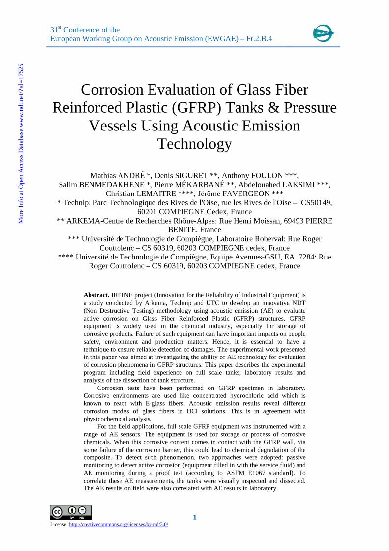
Various studies have shown that the corrosion of composites could be detected by this NDT method on composite specimens in tensile, flexural and fracture toughness test, with chemical attack [1]. However, all these studies were done with a combination of corrosion attack and mechanical stress. Experiments carried out in laboratory are corrosion tests of composite by different aggressive environments (hydrochloric acid, sulphuric acid, sodium hypochlorite, hydrofluoric acid) without mechanical stress. Cylindrical cell (figure 1) was designed to hold acid. It is made in Polytetrafluoroethylen (PTFE).
Fig. 1. Experimental setup of the corrosion tests monitored by acoustic emission
We see on the figure 2 that the different environments will create different acoustic
emission activity.
3
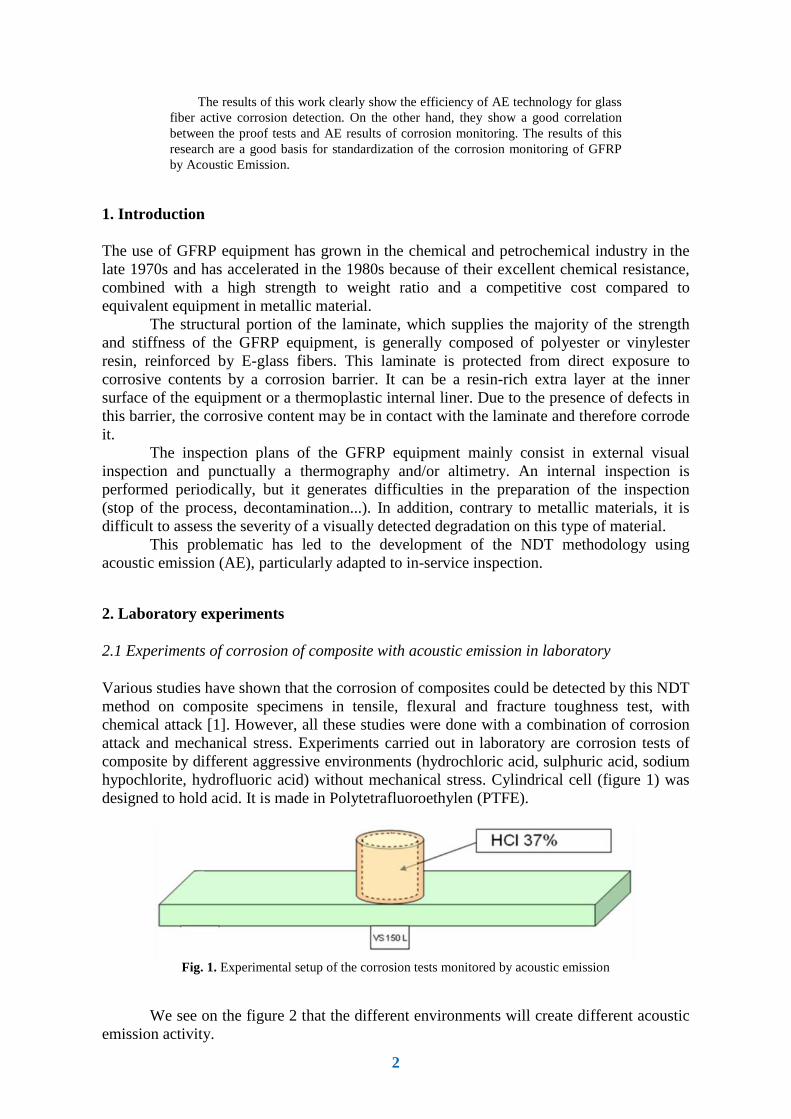
Fig. 2. Different acoustic emission activity due to different aggressive environments
2.2 Corrosion of composite by Hydrochloric acid
Fig. 3. Picture of consequences of the corrosion on GFRP
Further investigations have been made on the corrosion of composite by hydrochloric acid. Mineral acid like hydrochloric acid is known to react with the glass fiber. The corrosion of glass fibers in mineral acid solution is less known but very important. Indeed, this corrosion is thought to be responsible of GRP failure (Figure 3). We have shown in a previous work [2] that the variation of cumulative events with time is proportional to the microstructure. Thanks to the progress of signal acquisition and treatment technology, it is now possible to save more information from recorded signals. Thus, it is
possible to determine the specific acoustic signatures of observed phenomena. Clustering of the different hit is done by using k-mean algorithmic (figure 4). Three different clusters have been found [3]. Now, these different clusters have to be related to the observed phenomena.
Fig. 4. Result of k-mean algorithm on hits in the principal component vector space
-10 -8 -6 -4 -2 0 2 4 6 8-2
0
2
4
6
8
10
12
14
1er CP
2èm
e C
P
1 cm
HCl 5% + 16000 ppm HF H2SO4 98%
Sodium hypochlorite 40% HCl 36 %
4
3. AE Monitoring on full scale GFRP tank
3.1 Experimental method
One horizontal GFRP tank was evaluated during a passive monitoring and a proof test. The proof test was performed according to ASTM E1067 standard [4]. The capacity of the tank is 3m3, with an internal diameter of 1 000 mm, and a length of 4 300 mm. The wall is composed of a maximum 10 mm thick GFRP laminate (vinylester resin reinforced with E glass fibers), with a 5 mm thick inner PVDF liner. The tank has been in service for 23 years at the time of the tests. The in-service stored liquid is bromine (Br2), with a maximum liquid level of 70% of the tank capacity.
Fig. 5. Loading sequence of the AE proof test on GFRP tank.
For the passive monitoring, the bromine level was held at the in service level (70%) for 2 hours. For the AE proof test, the bromine was replaced with water (for safety reasons). Due to density difference, the water was pressurised up to a Pmax, pressure equal to 110% of the maximum pressure applied in service. The maximum pressure applied in service is equivalent to the in-service bromine liquid level. Figure 5 shows the loading sequence. The initial hold period (0 mbar) and the hold period at Pmax (190 mbar) were at least for 30
minutes.The intermediate hold periods were at least for 4 minutes. At the end of the sequence, an unloading followed by a reloading were applied in order to verify the Felicity effect.
Fig. 6 and 7 show, respectively, the sensor layout on the tank for the passive monitoring and for the proof test. For the passive monitoring, the sensor layout is composed of 10 sensors and aims at covering the portion of the tank in contact with the liquid. For the proof test, the sensor layout is composed of 20 sensors and aims at covering the whole structure of the tank. For both tests, AE signals were recorded with 35dB acquisition threshold; gain of preamplifiers was 34dB; sensors were resonant at around 200 kHz.
Fig. 6. Sensor layout on GFRP tank for the passive monitoring.
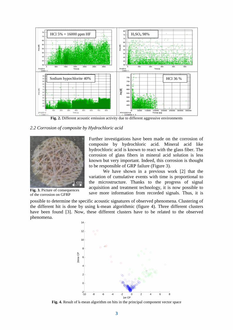
Fig. 7. Sensor layout on GFRP tank for the AE proof test.
3.2 AE Results
3.2.1 Passive monitoring of active corrosion phenomena
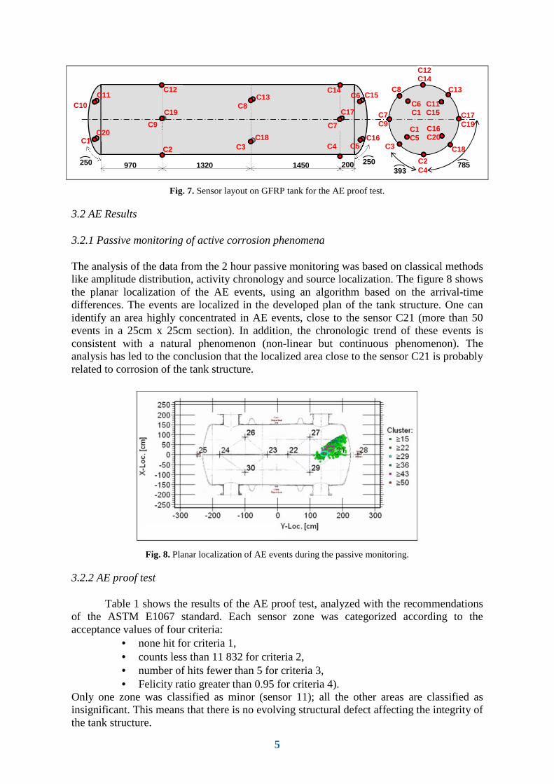
The analysis of the data from the 2 hour passive monitoring was based on classical methods like amplitude distribution, activity chronology and source localization. The figure 8 shows the planar localization of the AE events, using an algorithm based on the arrival-time differences. The events are localized in the developed plan of the tank structure. One can identify an area highly concentrated in AE events, close to the sensor C21 (more than 50 events in a 25cm x 25cm section). In addition, the chronologic trend of these events is consistent with a natural phenomenon (non-linear but continuous phenomenon). The analysis has led to the conclusion that the localized area close to the sensor C21 is probably related to corrosion of the tank structure.
Fig. 8. Planar localization of AE events during the passive monitoring.
3.2.2 AE proof test
Table 1 shows the results of the AE proof test, analyzed with the recommendations of the ASTM E1067 standard. Each sensor zone was categorized according to the acceptance values of four criteria:
• none hit for criteria 1, • counts less than 11 832 for criteria 2, • number of hits fewer than 5 for criteria 3, • Felicity ratio greater than 0.95 for criteria 4).
Only one zone was classified as minor (sensor 11); all the other areas are classified as insignificant. This means that there is no evolving structural defect affecting the integrity of the tank structure.
785
C3 C1
C4
C9
1320 970 250
C12
C8
1450 200
C3 C18
C2 C4
C17 C19
C7 C9
C6 C1
C13
C19
C2
C14
C7
C17
C6 C15
C5 C16
C20
C10 C11
C18
C8 C13
C12 C14
C11 C15
C1 C5
C16 C20
250 393
6
Table 1. Results of the AE proof test.
Sensor Criteria 1 (*)
Criteria 2 (**)
Criteria 3 (***)
Criteria 4 (****)
Category (*****) Sensor Criteria
1 (*) Criteria 2 (**)
Criteria 3 (***)
Criteria 4 (****)
Category (*****)
1 0 121 0 ≥ 1 0 11 6 226 1 ≥ 1 I
2 0 672 0 ≥ 1 0 12 0 392 0 ≥ 1 0
3 0 599 0 ≥ 1 0 13 0 726 0 ≥ 1 0
4 1 357 0 ≥ 1 0 14 1 347 0 ≥ 1 0
5 0 477 0 ≥ 1 0 15 0 496 0 ≥ 1 0
6 0 397 0 ≥ 1 0 16 0 438 0 ≥ 1 0
7 0 412 0 ≥ 1 0 17 0 357 0 ≥ 1 0
8 0 883 1 ≥ 1 0 18 0 579 1 ≥ 1 0
9 1 788 0 ≥ 1 0 19 1 729 0 ≥ 1 0
10 2 114 0 ≥ 1 0 20 0 116 0 ≥ 1 0
(*) Criteria 1: Hits during hold, with amplitude greater than low amplitude threshold (46dBAE), beyond 2 minutes (**) Criteria 2: Total counts (***) Criteria 3: Hits with amplitude greater than high-amplitude threshold (76dBAE) (****) Criteria 4: Felicity ratio (*****) Category: 0: Insignificant I: Minor II: intermediate III: Follow-up IV: Major
4. Further laboratory investigations for correlation of AE field results
4.1 Dissection of tank
After AE measurements, the tank was removed from service, dissected and inspected. The inspection was focused on the emissive area detected and localised during the AE passive monitoring. The figures 9(a) and 9(b) illustrate the observations performed on the internal PVDF liner. The visual inspection, figure 9(a), shows that the internal surface of the liner is colored because of the bromine migration, but no macroscopic crack or blister is visible. Micrographic examination, figure 9(b) reveals some micro-cracks, close to the weld seams.
Fig. 9. Inspection of the PVDF liner (a) visual (b) micrography
The PVDF liner is fixed to a synthetic fiber fabric which provides the adhesion
between the liner and the GFRP laminate. In the emissive area, the liner is easily detached from the laminate; some bromine spots are visible at the interface liner/laminate. In the non-emissive area, the liner is well attached to the laminate. No bromine spot is visible at the interface liner/laminate.
Examination of laminate was also performed. In all areas (emissive and non-emissive), the laminate does not have crack or porosity. The Barcol hardness measured on
Dark area observed through the liner
(a) Microscopic crack (b)
7
Table 2. Hardness measurements on dissected tank.
Barcol hardness
Emissive area 37 ± 4
Non-emissive area 39 ± 4
the resin of the laminate is shown in the table 2 (mean values of 5 measurements). The measurements are consistent with those expected for this kind of GFRP structure (35-40). No difference is visible between emissive and non-emissive area.
Scanning electron microscopy with energy dispersive X-ray spectroscopy (SEM/EDX) investigations were performed on the interface between the liner and the laminate (figure 10 and table 3). The analysis of these investigations shows a slight diffusion front (≈ 100µm) of bromine in the resin of the laminate. This attack of resin is related to the detachment of the PVDF from the laminate.
Fig. 10. SEM pictures of the interface liner/laminate
Table 3. EDX results of the area from the figure 10.
PVDF Light resin Dark resin Mass
composition (%)
Atomic composition
(%)
Mass composition
(%)
Atomic composition
(%)
Mass composition
(%)
Atomic composition
(%) C 26,9 39,6 50,6 76,8 71,7 87,6
F 62,5 58,1
O 13,1 17,9 27,9 20,4
Br 10,5 2,3 36,3 8,3 1,4 0,2
4.2 Laboratory tests with Bromine
Fig. 11. GFRP specimen after corrosion test with bromine
Corrosion tests were performed on GFRP specimen in contact with bromine, monitored with 2 AE sensors. The dimensions of the specimen are 50 x 300 mm, cut from a healthy area of the dissected tank. The PVDF layer is removed from the specimen. No surface treatment is done (the synthetic fiber fabric is still present). Figure 11 shows the specimen after the corrosion test. AE data from this test were compared with the AE data from the passive monitoring on tank.
Cumulative amplitude distributions are shown in the figure 12 (Pollock plots). The slopes of these curves are similar for the laboratory test and for the field test. According to Pollock theory, this similarity confirms that the same failure mechanism is detected for both
PVDF
Synthetic fiber fabric
Light resin
Dark resin
Resin attack and detachment of fiber fabric
8
laboratory and field measurements. Other AE parameters were compared to corroborate this similarity.
Fig. 12. Cumulative amplitude distributions (a) for the test on specimen (b) for the test on tank
5. Conclusion
The ability of AE technology to monitor corrosion phenomena in GFRP was evaluated by means of laboratory tests, full scale tests and correlation with dissection. Results are summarized below. • The use of acoustic emission for damage monitoring of composite materials is a classic
and several standards describe this application. In the present applied research work, it is clearly demonstrated the efficacy of the acoustic emission for the detection and monitoring of composite corrosion phenomena. This is an original result.
• We can assume that the AE activity detected during the passive monitoring of the tank is related to the corrosion attack of the interface between the inner liner and the laminate. This proposition is reinforced by the similarity of acoustic emission activity recorded on field and in the laboratory.
• The visual and mechanical examinations of the dissected tank conclude that there is no damage of the structural laminate. This is consistent with the AE results from the proof test indicating that no structural defect is detected by AE.
Acknowledgment
The present works were conducted in the frame of IREINE project, supported by OSEO, FEDER (Fonds Européen de Développement Economique et Régional) and GRAND LYON.
References
[1] L. Jones, J. Stewart, “The kinetics of corrosion of e-glass fibres in sulphuric acid“, journal of Non-Crystalline Solids 356 (2010) 2433-2436 [2] A. Foulon, A. Laksimi, C. Lemaitre, J. Favergeon “Displaying acidic corrosion prominently of composites (GRP) by microanalysis and acoustic emission”, JNC, 2013 [3] A. Foulon, A. Laksimi, C. Lemaitre, J. Favergeon “Use of acoustic emission technique for in service evaluation of the mechanical integrity of equipment GRP (Glass reinforced plastic)”, ECCM16, 2014 [4] ASTM E1067, “Standard Practice for Acoustic Emission Examination of Fiberglass Reinforced Plastic Resin (FRP) Tanks/Vessels“, ASTM International [5] Mechraoui S., Laksimi A., Benmedakhene S., “Reliability of damage mechanism localisation by acoustic emission on glass/epoxy composite material plate“, Composite Structures 94 (2012) 1483-1494