+ All Categories
Home > Documents > C.R. Laurence Co., Inc. 2200 E. 55th ST

C.R. Laurence Co., Inc. 2200 E. 55th ST

Date post: 07-Jan-2022
Category:
Upload: others
View: 3 times
Download: 0 times
Share this document with a friend
29
03 March 2017 C.R. Laurence Co., Inc. 2200 E. 55 th ST Los Angeles, CA 90058-0923 SUBJ: CRL UNIVERSAL WALL MOUNTED GLASS AWNING BRACKET GAB24, GAB36, GAB48 The CRL universal wall mounted glass awning bracket utilizes stainless steel fittings to construct wall mounted cantilevered glass awnings using 9/16” two ply laminated tempered glass. The system is intended for interior and exterior weather exposed applications and is suitable for use in all natural environments. The system may be used for residential, commercial and industrial applications. The Glass Awning Brackets are designed for the following criteria: The design loading conditions are: Concentrated load = 50 lbs any direction, any location Uniform load = 25 psf vertical, live, wind (ASD level loads) or snow load Higher uniform loads may be allowed depending on glass strength and size as shown herein, refer to the awning size/load tables. Wind loads determined per ASCE/SEI 7-10 (2012 and 2015 IBC) shall be adjusted to ASD level. The glass awning is not intended to support significant concentrated live loads or personnel. It shall not be used to walk, stand or step on. The Glass Awning Brackets will meet applicable requirements of the 2006, 2009, 2012 and 2015 International Building Codes, and 2013 and 2016 California Building Codes. Stainless steel components are designed in accordance with SEI/ASCE 8-02 Specification for the Design of Cold-Formed Stainless Steel Structural Members or AISC Design Guide 27 Structural Stainless Steel as applicable. Anchorages to wood are designed in accordance with the National Design Specification for Wood Construction. Calculations Page Signature Page 2 Awning dimensions 3 Wall Mounting Bracket 4 – 5 Wall Mounting Bolts/Anchors 5 – 6 Allowable Bracket Loads 7 – 9 Glass Strength 14 - 18 Allowable Uniform Loads on Glass 19 - 28 RB50F Glass Fitting 29 Attachments – Bracket details 3 pages Edward Robison, P.E. Edward C. Robison, PE [email protected] 10012 Creviston DR NW 253-858-0855 Gig Harbor, WA 98329 FAX 253-858-0856
Transcript

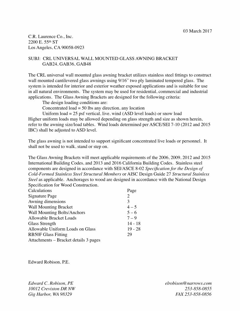
03 March 2017C.R. Laurence Co., Inc.2200 E. 55th STLos Angeles, CA 90058-0923

SUBJ: CRL UNIVERSAL WALL MOUNTED GLASS AWNING BRACKETGAB24, GAB36, GAB48

The CRL universal wall mounted glass awning bracket utilizes stainless steel fittings to construct wall mounted cantilevered glass awnings using 9/16” two ply laminated tempered glass. The system is intended for interior and exterior weather exposed applications and is suitable for use in all natural environments. The system may be used for residential, commercial and industrial applications. The Glass Awning Brackets are designed for the following criteria:

The design loading conditions are:Concentrated load = 50 lbs any direction, any locationUniform load = 25 psf vertical, live, wind (ASD level loads) or snow load

Higher uniform loads may be allowed depending on glass strength and size as shown herein, refer to the awning size/load tables. Wind loads determined per ASCE/SEI 7-10 (2012 and 2015 IBC) shall be adjusted to ASD level.

The glass awning is not intended to support significant concentrated live loads or personnel. It shall not be used to walk, stand or step on.

The Glass Awning Brackets will meet applicable requirements of the 2006, 2009, 2012 and 2015 International Building Codes, and 2013 and 2016 California Building Codes. Stainless steel components are designed in accordance with SEI/ASCE 8-02 Specification for the Design of Cold-Formed Stainless Steel Structural Members or AISC Design Guide 27 Structural Stainless Steel as applicable. Anchorages to wood are designed in accordance with the National Design Specification for Wood Construction.Calculations PageSignature Page 2Awning dimensions 3Wall Mounting Bracket 4 – 5Wall Mounting Bolts/Anchors 5 – 6Allowable Bracket Loads 7 – 9Glass Strength 14 - 18Allowable Uniform Loads on Glass 19 - 28RB50F Glass Fitting 29Attachments – Bracket details 3 pages

Edward Robison, P.E.

Edward C. Robison, PE [email protected] Creviston DR NW 253-858-0855Gig Harbor, WA 98329 FAX 253-858-0856

C.R. Laurence Glass Awning Brackets 03/03/2017 Page ! of !2 29

Signature Page:

Edward C. Robison, PE [email protected] Creviston DR NW 253-858-0855Gig Harbor, WA 98329 FAX 253-858-0856

Sealed 03 March 2017

42123EDWARD C.ROBISON

NO. 63683

STATE OF

EXP 02/28/2019

ED

WARD C. ROBISON

HA WA II U. S.

A.

LICENSEDPROFESSIONAL

ENGINEERNo. 11576-S

EXP 04/30/2018

EDWARD C.ROBISON12/31/2017

17546

OREGON

18195PE

EXP 12/31/2018

STAT

E

OF WASHINGTON

29129REGIST ERE D

73556

EDWARD C. ROBISON

EXP 09/30/2017FIRM #F-12044EXP 12/31/2017

Edward C. Robison

088030

EXP 03/31/2018

EDWARD C.ROBISON

081.007077

EXP 11/30/2018

EXP 03/31/2020

EDWARD C.ROBISON

STRUCTURALNo. 49757

EXP 06/30/2018

C.R. Laurence Glass Awning Brackets 03/03/2017 Page ! of !3 29

CRL GLASS AWNING SUPPORT SYSTEMSupport hardware for flat panel awnings such as tempered laminated glass.

Dimensions a and c ≥ 2”.Dimension b is either 17”, 29” or 41”Dimension d ≥ 2”Dimension e based on allowable bracket load and glass strength.

Edward C. Robison, PE [email protected] Creviston DR NW 253-858-0855Gig Harbor, WA 98329 FAX 253-858-0856

e = center span length

L = overall glass lengthB

= g

lass

wid

th

d2"

min

c2"

min

1/4

b m

ax

a a

b

e = center span length

L = overall glass length

B =

gla

ss w

idth

d2"

min

c2"

min

1/4

b m

ax

a a

b

2 7/8"

5 3/4"

C.R. Laurence Glass Awning Brackets 03/03/2017 Page ! of !4 29

�GAB24 Bracket

�GAB36 Bracket

�GAB48 Bracket

Edward C. Robison, PE [email protected] Creviston DR NW 253-858-0855Gig Harbor, WA 98329 FAX 253-858-0856

C.R. Laurence Glass Awning Brackets 03/03/2017 Page ! of !5 29

SLOPED BRACKETS:Sloped brackets provided a slope of 1 to 12 away from the wall.

Edward C. Robison, PE [email protected] Creviston DR NW 253-858-0855Gig Harbor, WA 98329 FAX 253-858-0856

C.R. Laurence Glass Awning Brackets 03/03/2017 Page ! of !6 29

Edward C. Robison, PE [email protected] Creviston DR NW 253-858-0855Gig Harbor, WA 98329 FAX 253-858-0856

C.R. Laurence Glass Awning Brackets 03/03/2017 Page ! of !7 29

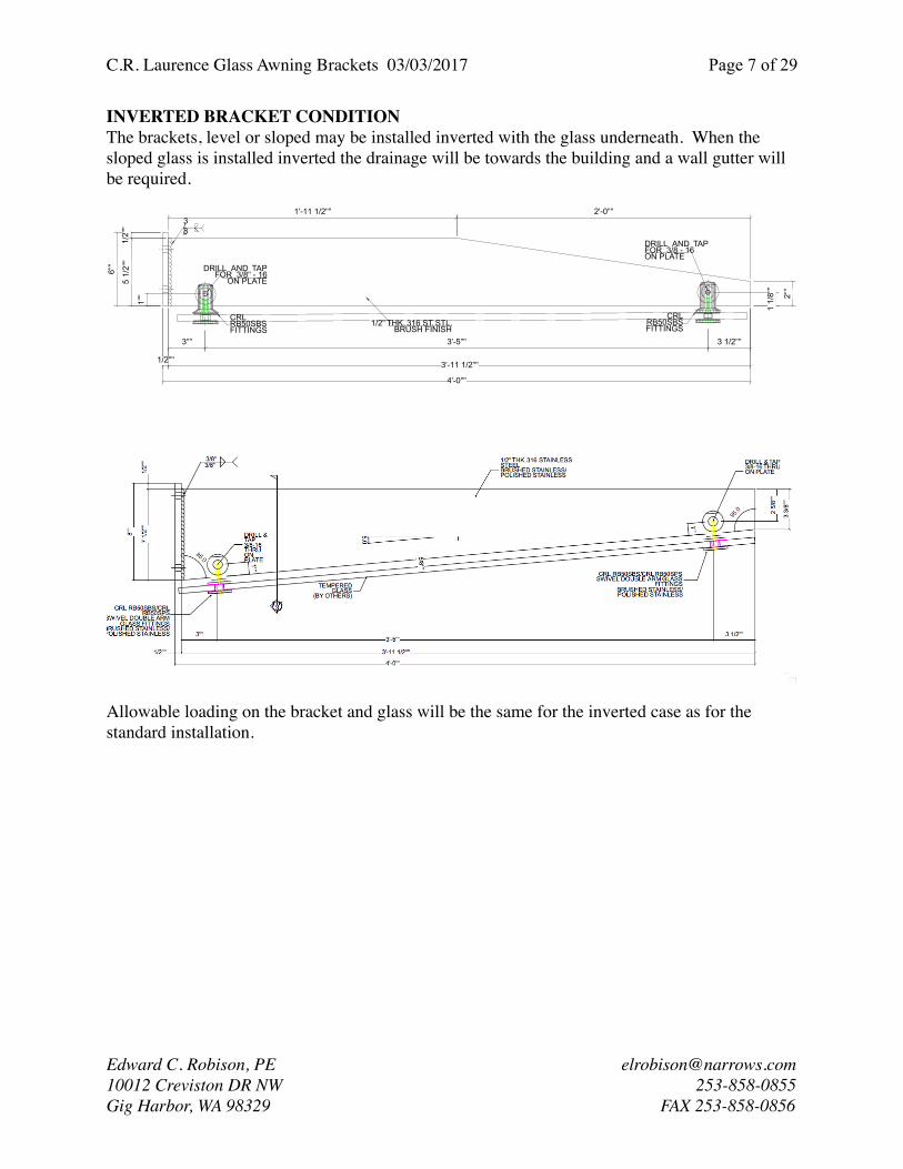
INVERTED BRACKET CONDITIONThe brackets, level or sloped may be installed inverted with the glass underneath. When the sloped glass is installed inverted the drainage will be towards the building and a wall gutter will be required.

Allowable loading on the bracket and glass will be the same for the inverted case as for the standard installation.

Edward C. Robison, PE [email protected] Creviston DR NW 253-858-0855Gig Harbor, WA 98329 FAX 253-858-0856

3"" 3'-5"" 3 1/2""

2""

4'-0""

DRILL AND TAPFOR 3/8" - 16

ON PLATE

1/2""

6""

2'-0""1'-11 1/2""

1/2" THK. 316 ST. STL.BRUSH FINISH

CRLRB50SBSFITTINGS

CRLRB50SBSFITTINGS

DRILL AND TAPFOR 3/8 - 16ON PLATE

1/2"

"5

1/2"

"

3'-11 1/2""

1 1/

8""

1""

3/8"

C.R. Laurence Glass Awning Brackets 03/03/2017 Page ! of !8 29

WALL MOUNT

All bracket sizes use the same wall mount. Bracket bar is welded to the wall plate which is bolted to the wall.

Fabricated from 304 stainless steel

Check strength of bar weld to wall plate:3/8” bevel weld with convex finish both sides. Weld filler is E316

The weld will provide full penetration weld and develop full bar strength.

Tension strength of weld:Pn = LtFua = 6”*0.5”*75ksi = 225k

Shear strength of weld at wall plate:Vn = (0.7-0.009L/t)tLFuaVn = (0.7-0.009*6/.75)(2*0.375”)*6”*75ksi = 211.95kor: Vn = 0.75twLFxx = 0.75*(0.707*.375*2)*6”*75ksi = 178.96k

Vs = 0.65*178.96k = 116.3k ≤ 0.55*211.95 = 116.57k

Allowable moment on the bracket based on weld strength:

Mn = 6”/2*116.3k = 348.9k”

Strength of bar at edge of weld:Z = 0.5”*6”2/4 = 4.5 in3

øMn = 0.9*4.5in3*30ksi = 121.5k” (bar yield strength controls load).

Maximum factored moment on the bar [1.2D+(1.6S or 1.6W)] or [1.2D+0.75(W+S)]or for uplift [0.9D+1.6W]Mu = 121.5k”

Design attachment to wall for the imposed moment:Loads resisted by couple formed between bolts and plate edge, rotation about edge of plate.

Edward C. Robison, PE [email protected] Creviston DR NW 253-858-0855Gig Harbor, WA 98329 FAX 253-858-0856

C.R. Laurence Glass Awning Brackets 03/03/2017 Page ! of !9 29

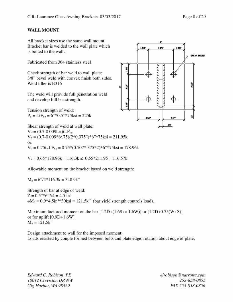
Maximum bolt tension based on plate bending: Plate bending will occur along a diagonal line from top edge face of bar to edge of plate near other bolt.

bend length = 2.75”+2.75”*√2 = 6.64”Moment arm = 1.375”Z = 6.64”*0.52/4 = 0.415in3

øMnp = 0.9*45 ksi*0.415in3 = 16,807#”

Maximum bolt tension based on wall plate bending :M = T*1.375” = øMn = 16,807#”T =16,807#”/1.375 = 12,223#

Check maximum bolt tension based on bracket plate strength:Bolt tension from ∑M about edge of wall plate:M = 0 = 4.625”*T*2 + 1.375”*(1.375/4.625)*T*2 +MuT = 121,000#”/[2*4.625+1.375*1.375/4.625] = 12,527#

Check strength based on anchor alternatives:1/2” Bolts:At = 0.1419 in2

Fnt = 100,000 psi DIN 933-A2 or strongerøPn = øAtFnt = 0.75*0.1419in2*100,000psi = 10,642#Shear load will be carried by the bolts closest to the compression face of the couple which will be lightly loaded in tension so no reduction for shear load is required.

For bolting to steel frame the maximum moment based on the bolt tension:Ms = 10,642#*[2*4.625+1.375*1.375/4.625] = 102,793#”

For bolting to wood:For through bolts the maximum bolt tension can be the same as for steel provided proper bearing plates are used on the nut side (3” x 3” x 1/4” plates or equivalent round washer).

For 1/2” Lag screws into Douglas Fir or Southern Pine: W = 378#/in, Minimum embedment depth of 5” (Lag into 6x beam or solid block)W’ = W*CD = 375#”*1.15 for snow loads or 375#”*1.6 for wind loads (ASD level)Ta5 = 5”*378#”*1.15 = 2,175# for snow loadsMalag = 2,175#*#*[2*4.625+1.375*1.375/4.625] = 21,008#”

Ta5 = 5”*378#”*1.6 = 3,024# for wind loadsMalag = 3,024#*#*[2*4.625+1.375*1.375/4.625] = 29,208#”

Edward C. Robison, PE [email protected] Creviston DR NW 253-858-0855Gig Harbor, WA 98329 FAX 253-858-0856

C.R. Laurence Glass Awning Brackets 03/03/2017 Page ! of !10 29

For bolting to concrete:Hilti Kwik Bolt TZ in accordance with ESR-1917.1/2” diameter with 4” minimum embedment

Minimum conditions used for the calculations:f’c ≥ 3,000 psiedge distance = 2.75” minimum2 bolt group (consider only anchors in full tension load)For concrete breakout strength:Ncbg = [ANc/ANco]ϕed,Nϕc,Nϕcp,NNb

ANcg= (2.75”+1.5*4”)*(1.5*4”*2+3.25) = 133.4in2 For anchor groupANco= 9*42 = 144in2

Cac,min = 1.5*4” = 6Cac = 2.5*4” = 10ϕed,N = 1.0 ϕc,N = 1.4 (post installed)ϕcp,N= 6/10 = 0.6 (ca,min ≤cac)Nb = 17*1.0*√3000*41.5 = 7,449#Ncb = 133.4/144*1.0*1.4*0.6*7,449 = 5,798#based on concrete breakout strength.Pullout strength = 2*5,760# = 11,520#Steel strength:Nts = 92,000psi*0.101in2 = 9,292# (each)

Concrete breakout strength in shear:Vcb = Avc/Avco(ϕed,Vϕc,Vϕh,VVb

Avc = 3(ca1)*4” = 3(2.75”)*4” = 33.0Avco= 4.5(ca1)2 = 4.5(2.75)2 = 34.0ϕed,V= 1.0 (affected by only one edge)ϕc,V= 1.4 uncracked concreteϕh,V= √(1.5ca1/ha) = √(1.5*2.75/4) =1.016Vb= [7(le/da)0.2√da]λ√f’c(ca1)1.5 = [7(2/0.5)0.2√0.5]1.0√3000(2.75)1.5 =1,631#Vcb = 33.0/34.0*1.0*1.4*1.016*1,631# = 2,252#

Factored moment:Msc = 0.75*11,520*4.625” = 39,960#”Service MomentMs = 39,960”#/1.6 = 24,975”#

Limit based on RB50F glass fitting strength (see page 29)u ≤ 2*429 = 858# for two fittings per bracketu ≤ 4*429 = 1,716# for four fittings per bracketFor higher loads heavy duty spider fittings may be used in place of the RB50F fittings

Edward C. Robison, PE [email protected] Creviston DR NW 253-858-0855Gig Harbor, WA 98329 FAX 253-858-0856

C.R. Laurence Glass Awning Brackets 03/03/2017 Page ! of !11 29

SUMMARY OF ALLOWABLE BRACKET LOADS BASED ON ANCHORAGE

Glass width B is matched to bracket length.For each size bracket determine maximum allowable loads on awning:Based on M = R*L/2 or R = 2M/Lwhere R is total allowable load on bracket and L = bracket length and glass width.*May be limited by the glass fitting strength.

FOR GLASS WIDTHS OTHER THAN THE BRACKET LENGTH:

Bglass = glass width measured from face of wall to outside edge of glass. This may be larger than the actual glass width.Linear interpolation is permitted.Allowable loads for other glass widths may be calculated from the equation: Ra = 2Ma/Bglass *May be limited by the glass fitting strength.

The total loads shall not exceed the loads above for the load combinations:S + D W + DW - D (negative pressure) or0.5S+ W + D positive wind orS + 0.5W + D positive wind

D = 6.5 psf of 9/16D = 8.9 psf for 11/16D = 10.0 psf for 13/16

R = L*B*u/2

Table 1A: Load Limit Bracket Total Load lbs* Anchor Ma"# GAB24 GAB36 GAB48Steel 102793 8566 5711 4283

Concrete 24975 2081 1388 1041Wood-snow 21008 1751 1167 875Wood-wind 29208 2434 1623 1217

Table Formula Ma"# 2×Ma"#/24" 2×Ma"#/36" 2×Ma"#/48"

Table 1B: Load Limit Bracket Total Load lbs* Anchor Ma"# Bglass = 24 Bglass = 36 Bglass = 48 Bglass = 54 Bglass = 60Steel 102793 8566 5711 4283 3807 3426

Concrete 24975 2081 1388 1041 925 833Wood-snow 21008 1751 1167 875 778 700Wood-wind 29208 2434 1623 1217 1082 974

Table Formula Ma"# 2×Ma"#/

24" 2×Ma"#/

36" 2×Ma"#/

48" 2×Ma"#/

54" 2×Ma"#/

60"

Edward C. Robison, PE [email protected] Creviston DR NW 253-858-0855Gig Harbor, WA 98329 FAX 253-858-0856

C.R. Laurence Glass Awning Brackets 03/03/2017 Page ! of !12 29

For GAB24:Glass width, B = 24”Bracket weight: Db = [0.5”*(6+2)/2]*24”*0.28#/ci +2*1.3# = 16#For 9/16” laminated glass (1/4”+.05”+1/4”) Dg = 2*2.9+0.5 = 6.3 psfL = glass length (ft)MDf = 16#*12”+(6.3psf*2’*L/2)*12” = 192#”+(75.6L)#”Snow load or Wind (ASD level) loadSb = (Spsf*2’*L/2) = S*L plfWb = (Wpsf*2’*L/2) = W*L plfMbS = S*L plf*12”MbW = W*L plf*12”

For service loads (Steel or concrete)Ms = 1.2*(192#”+(75.6L)#”) + 1.6(S*L#*12”) = 230.4#”+90.72L+19.2S*L or Ms = 1.2*(192#”+(75.6L)#”) + 1.6(W*L#*12”) = 230.4#”+90.72L+19.2W*L orMs = 1.2*(192#”+(75.6L)#”) + 0.75[(S+W)*L#*12”] = 230.4#”+90.72L+9(S+W)*L orMs = 0.9*(192#”+(75.6L)#”) + 1.6(W*L#*12”) = 172.8#”+68.0L+19.2W*L for uplift

Based on glass strength the maximum bracket spacing, e = 8’-0” for 1/2” glass and 25 psf wind (ASD level) or snow load. The maximum cantilever length, d = 4’-0”

Check brackets based on the maximum allowable length of 16’ (4’+8’+4’) with 25 psf load. Ms = 230.4 + 90.72*16’ + 19.2*25psf*16’ = 9,362#” orMs = 230.4#”+90.72*16+9(25+25)*16 = 8,882#”Ms = 172.8#”+68.0*16 - 19.2*25*16 = -6,419#” for uplift

For allowable loads (wood)Ma = (192#”+(75.6L)#”) + (S*L#*12”) = 192#”+75.6L+12S*L or Ma = (192#”+(75.6L)#”) + (W*L#*12”) = 192#”+75.6L+12W*L orMa = (192#”+(75.6L)#”) + 0.75[(S+W)*L#*12”] = 192#”+75.6L+9(S+W)*L orMa = 0.6(192#”+(75.6L)#”) + (W*L#*12”) = 115.2#”+45.36L+12W*L for uplift

Check brackets based on the maximum allowable length of 16’ (4’+8’+4’) with 25 psf load. Ma = 192#”+75.6*16+12*25*16 = 6,202#” or Ma = 192#”+75.6*25+9(25+25)*16 = 6,882#” orMa = 115.2#”+ 45.36*16 - 12*25*16 = -3,959#” for uplift

Attachments to wood, concrete or steel are adequate for the maximum canopy size and 25 psf wind (ASD level) or snow loads.

Edward C. Robison, PE [email protected] Creviston DR NW 253-858-0855Gig Harbor, WA 98329 FAX 253-858-0856

C.R. Laurence Glass Awning Brackets 03/03/2017 Page ! of !13 29

For GAB36:Glass width, B = 36”Bracket weight: Db = [0.5”*{(6+2)/2*24”+12*6}]*0.28#/ci +2*1.3# = 26.1#For 9/16” laminated glass (1/4”+.05”+1/4”) Dg = 2*2.9+0.5 = 6.3 psfL = glass length (ft)MDf = 26.1#*18”+(6.3psf*3’*L/2)*18” = 469.8#”+(170.1L)#”Snow load or Wind (ASD level) loadSb = (Spsf*3’*L/2) = 1.5S*L plfWb = (Wpsf*3’*L/2) = 1.5W*L plfMbS = 1.5S*L plf*18” = 27SLMbW = 1.5W*L plf*18” = 27SL

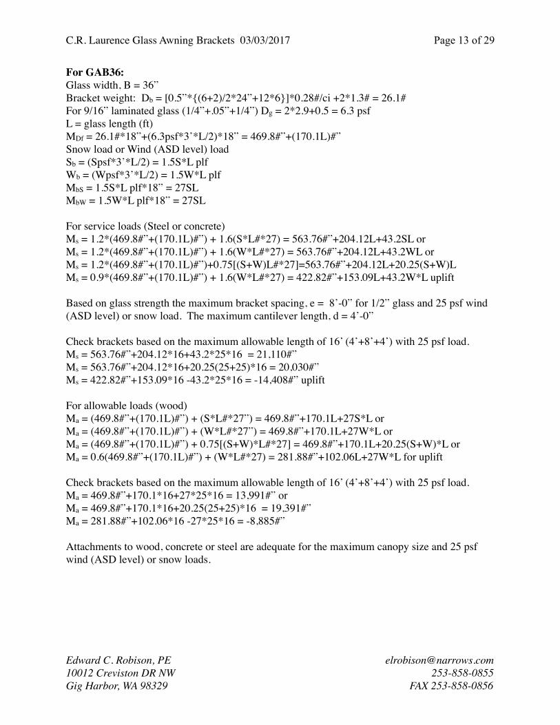
For service loads (Steel or concrete)Ms = 1.2*(469.8#”+(170.1L)#”) + 1.6(S*L#*27) = 563.76#”+204.12L+43.2SL or Ms = 1.2*(469.8#”+(170.1L)#”) + 1.6(W*L#*27) = 563.76#”+204.12L+43.2WL orMs = 1.2*(469.8#”+(170.1L)#”)+0.75[(S+W)L#*27]=563.76#”+204.12L+20.25(S+W)L Ms = 0.9*(469.8#”+(170.1L)#”) + 1.6(W*L#*27) = 422.82#”+153.09L+43.2W*L uplift

Based on glass strength the maximum bracket spacing, e = 8’-0” for 1/2” glass and 25 psf wind (ASD level) or snow load. The maximum cantilever length, d = 4’-0”

Check brackets based on the maximum allowable length of 16’ (4’+8’+4’) with 25 psf load. Ms = 563.76#”+204.12*16+43.2*25*16 = 21,110#”Ms = 563.76#”+204.12*16+20.25(25+25)*16 = 20,030#” Ms = 422.82#”+153.09*16 -43.2*25*16 = -14,408#” uplift

For allowable loads (wood)Ma = (469.8#”+(170.1L)#”) + (S*L#*27”) = 469.8#”+170.1L+27S*L or Ma = (469.8#”+(170.1L)#”) + (W*L#*27”) = 469.8#”+170.1L+27W*L orMa = (469.8#”+(170.1L)#”) + 0.75[(S+W)*L#*27] = 469.8#”+170.1L+20.25(S+W)*L orMa = 0.6(469.8#”+(170.1L)#”) + (W*L#*27) = 281.88#”+102.06L+27W*L for uplift

Check brackets based on the maximum allowable length of 16’ (4’+8’+4’) with 25 psf load. Ma = 469.8#”+170.1*16+27*25*16 = 13,991#” orMa = 469.8#”+170.1*16+20.25(25+25)*16 = 19,391#”Ma = 281.88#”+102.06*16 -27*25*16 = -8,885#”

Attachments to wood, concrete or steel are adequate for the maximum canopy size and 25 psf wind (ASD level) or snow loads.

Edward C. Robison, PE [email protected] Creviston DR NW 253-858-0855Gig Harbor, WA 98329 FAX 253-858-0856

C.R. Laurence Glass Awning Brackets 03/03/2017 Page ! of !14 29

For GAB48:Glass width, B = 48”Bracket weight: Db = [0.5”*{(6+2)/2*24”+24*6}]*0.28#/ci +2*1.3# = 36.2#For 9/16” laminated glass (1/4”+.05”+1/4”) Dg = 2*2.9+0.5 = 6.3 psfL = glass length (ft)MDf = 36.2#*20”+(6.3psf*4’*L/2)*24” = 724#”+(302.4L)#”Snow load or Wind (ASD level) loadSb = (Spsf*4’*L/2) = 2S*L plfWb = (Wpsf*4’*L/2) = 2W*L plfMbS = 2S*L plf*24” = 48SLMbW = 2W*L plf*24” = 48SL

For service loads (Steel or concrete)Ms = 1.2*(724#”+(302.4L)#”) + 1.6(S*L#*48) = 868.8#”+362.88L+76.8SL or Ms = 1.2*(724#”+(302.4L)#”) + 1.6(W*L#*48) = 868.8#”+362.88L+76.8WL orMs = 1.2*(724#”+(302.4L)#”) +0.75[(S+W)L#*48]=868.8#”+362.88L+36(S+W)L Ms = 0.9*(724#”+(302.4L)#”) + 1.6(W*L#*48) = 651.6#”+272.16L+76.8W*L uplift

Based on glass strength the maximum bracket spacing, e = 8’-0” for 1/2” glass and 25 psf wind (ASD level) or snow load. The maximum cantilever length, d = 4’-0”

Check brackets based on the maximum allowable length of 16’ (4’+8’+4’) with 25 psf load. Ms = 868.8#”+362.88*16+76.8*25*16 = 37,395#” orMs = 868.8#”+362.88*16+36(25+25)*16 = 35,475#” Ms = 651.6#”+272.16*16 - 76.8*25*16 = -25,714#” uplift

For allowable loads (wood)Ma = (724#”+(302.4L)#”) + (S*L#*48”) = 724#”+302.4L+48S*L or Ma = (724#”+(302.4L)#”) + (W*L#*48”) = 724#”+302.4L+48W*L orMa = (724#”+(302.4L)#”) + 0.75[(S+W)*L#*48] = 724#”+302.4L+36(S+W)*L orMa = 0.6(724#”+(302.4L)#”) + (W*L#*48) = 434.4#”+181.44L+48W*L for uplift

Check brackets based on the maximum allowable length of 16’ (4’+8’+4’) with 25 psf load. Ma = 724#”+302.4*16+48*25*16 = 24,762#” orMa = 724#”+302.4*16+36 (25+25)*16 = 34,362#” > 21,008#”Ma = 434.4#”+181.44*16 -48*25*16 = -15,863#”

Lwood ≤ 21,008/34,362*16 = 9.78’ = 9’-9”For attachment to wood maximum length L = 9’-9”

Attachments to concrete and steel are adequate for the maximum canopy size and 25 psf wind (ASD level) or snow loads.

Edward C. Robison, PE [email protected] Creviston DR NW 253-858-0855Gig Harbor, WA 98329 FAX 253-858-0856

C.R. Laurence Glass Awning Brackets 03/03/2017 Page ! of !15 29

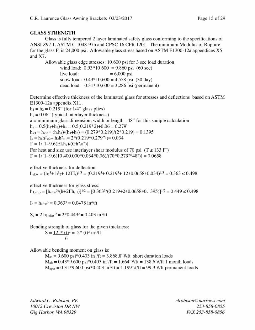
GLASS STRENGTHGlass is fully tempered 2 layer laminated safety glass conforming to the specifications of

ANSI Z97.1, ASTM C 1048-97b and CPSC 16 CFR 1201. The minimum Modulus of Rupture for the glass Fr is 24,000 psi. Allowable glass stress based on ASTM E1300-12a appendices X5 and X7.

Allowable glass edge stresses: 10,600 psi for 3 sec load durationwind load: 0.93*10,600 = 9,860 psi (60 sec)live load: = 6,000 psisnow load: 0.43*10,600 = 4,558 psi (30 day)dead load: 0.31*10,600 = 3,286 psi (permanent)

Determine effective thickness of the laminated glass for stresses and deflections based on ASTM E1300-12a appendix X11.h1 = h2 = 0.219” (for 1/4” glass plies) hv = 0.06” (typical interlayer thickness)a = minimum glass dimension, width or length - 48” for this sample calculationhs = 0.5(h1+h2)+hv = 0.5(0.219*2)+0.06 = 0.279”hs;1 = hs;2 = (hsh1)/(h1+h2) = (0.279*0.219)/(2*0.219) = 0.1395Is = h1h2s;2+ h2h2s;1= 2*(0.219*0.279”2)= 0.034Γ = 1/[1+9.6(EIshv)/(Gh2sa2)] For heat and size use interlayer shear modulus of 70 psi (T ≤ 133 F˚)Γ = 1/[1+9.6(10,400,000*0.034*0.06)/(70*0.2792*482)] = 0.0658

effective thickness for deflection:hef;w = (h13+ h32+ 12ΓIs)1/3 = (0.2193+ 0.2193+ 12∗0.0658∗0.034)1/3 = 0.363 ≤ 0.498

effective thickness for glass stress:h1;ef;σ = [hef;w3/(h+2Γhs;1)]1/2 = [0.3633/(0.219+2∗0.0658∗0.1395)]1/2 = 0.449 ≤ 0.498

Ie = hef;w3 = 0.3633 = 0.0478 in4/ft

Se = 2 h1;ef;σ 2 = 2*0.4492 = 0.403 in3/ft

Bending strength of glass for the given thickness:S = 12”* (t)2 = 2* (t)2 in3/ft

6

Allowable bending moment on glass is:Mas = 9,600 psi*0.403 in3/ft = 3,868.8”#/ft short duration loadsMalt = 0.43*9,600 psi*0.403 in3/ft = 1,664”#/ft = 138.6’#/ft 1 month loadsMaper = 0.31*9,600 psi*0.403 in3/ft = 1,199”#/ft = 99.9’#/ft permanent loads

Edward C. Robison, PE [email protected] Creviston DR NW 253-858-0855Gig Harbor, WA 98329 FAX 253-858-0856

C.R. Laurence Glass Awning Brackets 03/03/2017 Page ! of !16 29

Maximum bending moment will occur at center edge of the glass light:Mec = Ce*w*e2

Ce is from graph based on B/a where B is always the smaller dimension.When B/e < 0.33 Ce may be taken as 0.125, Ce is maximum of 0.1606 at B/e = 1.0For concentrated loadsMl = 2CePe for concentrated load P at the light center edgeMc = U*d2/2 at support axis

Mc = P*dd = length of cantilever past the supportsDead load equivalent load = 6.3/(0.31/0.83) = 16.9 (adjusted to 60 sec load equivalent) For a design load of W = 25 psf (wind (ASD level))U = 25+16.9 = 41.9 psfBased on assumed b/e ≤ 0.33 and width B = 24”, PVB interlayer

e = [(2,258”#/12)*8/41.9psf]1/2 = 5.994’ e = 2,258”#*4/50 = 180.6” concentrated loads won’t controld = [(2,258”#/12)*2/41.9psf]1/2 = 2.997’ Cantilevered lengthd = 2’*2,258”#/50 = 90” concentrated loads won’t control

Table 2

h1, h2

hv hs;1 hs;2 Is hs Allowable Moment , Mga, (“#/ft)

6mm 0.219 0.06 0.1395 0.0085 0.279

6mm 0.219 0.06 0.1395 0.0085 0.279

Short Dim.B

Γ PVB

Γ SGP

hef;w

PVBhef;w

SGPh1;ef;σ

PVBh1;ef;σ

SGPwind PVB

wind SGP

snow PVB

snow SGP

Dead PVB

Dead SGP

24 0.058 0.590 0.300 0.433 0.338 0.461 2258 4182 1044 1933 753 1394

36 0.121 0.764 0.322 0.463 0.364 0.479 2607 4525 1205 2092 869 1508

48 0.197 0.852 0.345 0.476 0.388 0.487 2964 4670 1370 2159 988 1556

54 0.237 0.879 0.356 0.481 0.398 0.489 3131 4712 1447 2178 1043 1570

60 0.278 0.900 0.367 0.484 0.408 0.490 3286 4743 1519 2192 1095 1581

66 0.317 0.916 0.377 0.486 0.417 0.492 3428 4766 1585 2203 1143 1588

72 0.356 0.928 0.386 0.488 0.425 0.493 3558 4784 1645 2211 1186 1594

Edward C. Robison, PE [email protected] Creviston DR NW 253-858-0855Gig Harbor, WA 98329 FAX 253-858-0856

C.R. Laurence Glass Awning Brackets 03/03/2017 Page ! of !17 29

The allowable uniform load may be calculated using:Us = [(Mga/Ce)/e2] orUs = [(Mga/(4Ce))/d2]

or for long term loads:

Ult = [(138.6/Ce)/e2] orUlt = [(138.6/(4Ce))/d2]

or for permanent loads:

Uper = [(99.9/Ce)/e2] orUper = [(99.9/(4Ce))/d2]

For multiple types of load:Us/Mas + Ult/Malt + Uper/Maper ≤ 1.0

Edward C. Robison, PE [email protected] Creviston DR NW 253-858-0855Gig Harbor, WA 98329 FAX 253-858-0856

0.125

0.130

0.135

0.140

0.145

0.150

0.155

0.160

0.165

0.3 0.4 0.5 0.6 0.7 0.8 0.9 1.0

Bending Moment plate edge

Ce

a/B

C.R. Laurence Glass Awning Brackets 03/03/2017 Page ! of !18 29

GLASS DEFLECTIONS

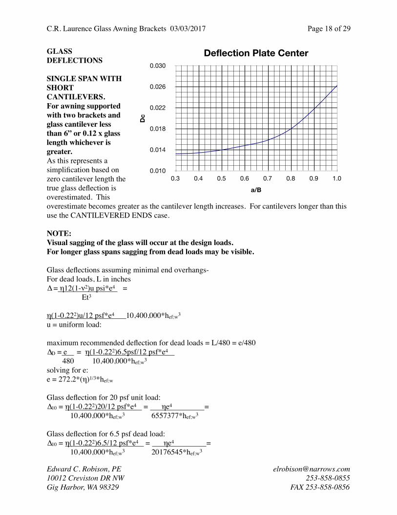
SINGLE SPAN WITH SHORT CANTILEVERS.For awning supported with two brackets and glass cantilever less than 6” or 0.12 x glass length whichever is greater.As this represents a simplification based on zero cantilever length the true glass deflection is overestimated. This overestimate becomes greater as the cantilever length increases. For cantilevers longer than this use the CANTILEVERED ENDS case.

NOTE:Visual sagging of the glass will occur at the design loads.For longer glass spans sagging from dead loads may be visible.

Glass deflections assuming minimal end overhangs-For dead loads, L in inches∆ = η12(1-ν2)u psi*e4 =

Et3

η(1-0.222)u/12 psf*e4 10,400,000*hef;w3

u = uniform load:

maximum recommended deflection for dead loads = L/480 = e/480 ∆D = e = η(1-0.222)6.5psf/12 psf*e4

480 10,400,000*hef;w3

solving for e:e = 272.2*(η)1/3*hef;w

Glass deflection for 20 psf unit load:∆10 = η(1-0.222)20/12 psf*e4 = ηe4 =

10,400,000*hef;w3 6557377*hef;w3

Glass deflection for 6.5 psf dead load:∆10 = η(1-0.222)6.5/12 psf*e4 = ηe4 =

10,400,000*hef;w3 20176545*hef;w3

Edward C. Robison, PE [email protected] Creviston DR NW 253-858-0855Gig Harbor, WA 98329 FAX 253-858-0856

0.010

0.014

0.018

0.022

0.026

0.030

0.3 0.4 0.5 0.6 0.7 0.8 0.9 1.0

Deflection Plate Center

Dc

a/B

C.R. Laurence Glass Awning Brackets 03/03/2017 Page ! of !19 29

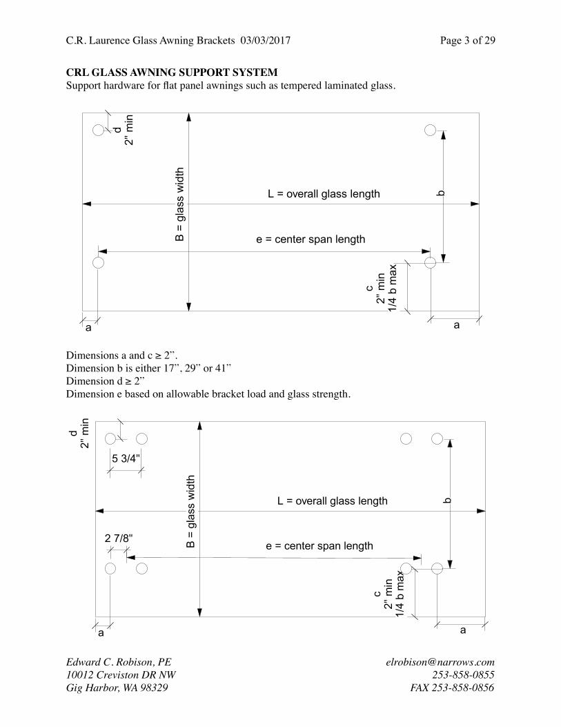
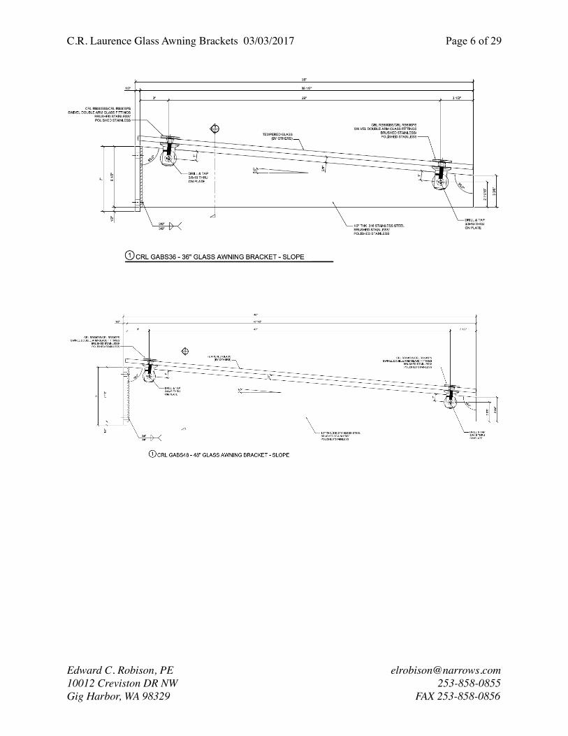
AWNING DIMENSIONS - SHORT CANTILEVERSFor use of these equations and the following tables to determine the allowable glass loads and deflections the awning dimensions shall be within the limits shown in this figure.

Edward C. Robison, PE [email protected] Creviston DR NW 253-858-0855Gig Harbor, WA 98329 FAX 253-858-0856

2"

MinimumMaximumGreater of6" or 1/8L

e = center span length

L = overall glass length

B =

gla

ss w

idth

1/4

B m

ax

2 FITTINGBRACKET

2"

MinimumMaximumGreater of6" or 1/8L

e = center span length

L = overall glass length

B =

gla

ss w

idth

1/4

B m

ax

5 3/4"

2 7/8"

4 FITTINGBRACKET

C.R. Laurence Glass Awning Brackets 03/03/2017 Page ! of !20 29

LOAD/DEFLECTION TABLES - SHORT CANTILEVERS

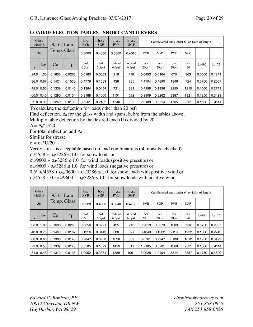
To calculate the deflection for loads other than 20 psf:Find deflection, ∆u for the glass width and spans, b, b/e from the tables above.Multiply table deflection by the desired load (U) divided by 20∆ = ∆u*U/20For total deflection add ∆dSimilar for stress:σ = σu*U/20Verify stress is acceptable based on load combinations (all must be checked):σs/4558 + σd/3286 ≤ 1.0 for snow loads orσw/9600 + σd/3286 ≤ 1.0 for wind loads (positive pressure) orσw/9600 - σd/3286 ≤ 1.0 for wind loads (negative pressure) or0.5*σs/4558 + σw/9600 + σd/3286 ≤ 1.0 for snow loads with positive wind orσs/4558 + 0.5σw/9600 + σd/3286 ≤ 1.0 for snow loads with positive wind

Glass width B 9/16” Lam.

Temp. Glass

hef;w

PVBhef;w

SGPh1;ef;σ

PVBh1;ef;σ

SGPCantilevered ends under 6” or 1/8th of length

24 0.3000 0.4330 0.3380 0.4610 PVB SGP PVB SGP

eb/e Ce η ∆ d

6.5psfPVB

∆ d6.5psfSGP

σ dead6.5psfPVB

σ dead6.5psfSGP

∆ u20psfPVB

∆ u20psfSGP

σ u20psfPVB

σ u20psf

L/480 L/175

24.0 1.00 0.1606 0.0263 0.0160 0.0053 219 118 0.0493 0.0164 675 363 0.0500 0.1371

36.0 0.67 0.1424 0.1550 0.4779 0.1589 438 235 1.4704 0.4890 1346 724 0.0750 0.2057

48.0 0.50 0.1339 0.0140 0.1364 0.0454 731 393 0.4198 0.1396 2250 1210 0.1000 0.2743

60.0 0.40 0.1290 0.0134 0.3188 0.1060 1101 592 0.9809 0.3262 3387 1821 0.1250 0.3429

72.0 0.33 0.1260 0.0133 0.6561 0.2182 1548 832 2.0188 0.6714 4765 2561 0.1500 0.4114

Glass width B 9/16” Lam.

Temp. Glass

hef;w

PVBhef;w

SGPh1;ef;σ

PVBh1;ef;σ

SGPCantilevered ends under 6” or 1/8th of length

36 0.3220 0.4630 0.3640 0.4790 PVB SGP PVB SGP

eb/e Ce η ∆ d

6.5psfPVB

∆ d6.5psfSGP

σ dead6.5psfPVB

σ dead6.5psfSGP

∆ u20psfPVB

∆ u20psfSGP

σ u20psfPVB

σ u20psf

L/480 L/175

36.0 1.00 0.1606 0.0263 0.0656 0.0221 425 246 0.2018 0.0679 1309 756 0.0750 0.2057

48.0 0.75 0.1460 0.0167 0.1316 0.0443 688 397 0.4049 0.1362 2116 1222 0.1000 0.2743

60.0 0.60 0.1386 0.0148 0.2847 0.0958 1020 589 0.8761 0.2947 3138 1812 0.1250 0.3429

72.0 0.50 0.1339 0.0140 0.5585 0.1879 1419 819 1.7185 0.5781 4366 2521 0.1500 0.4114

84.0 0.43 0.1310 0.0136 1.0052 0.3381 1889 1091 3.0928 1.0404 5814 3357 0.1750 0.4800

Edward C. Robison, PE [email protected] Creviston DR NW 253-858-0855Gig Harbor, WA 98329 FAX 253-858-0856

C.R. Laurence Glass Awning Brackets 03/03/2017 Page ! of !21 29

Glass width B 9/16” Lam.

Temp. Glass

hef;w

PVBhef;w

SGPh1;ef;σ

PVBh1;ef;σ

SGPCantilevered ends under 6” or 1/8th of length

48 0.3450 0.4760 0.3880 0.4870 PVB SGP PVB SGP

eb/e Ce η ∆ d

6.5psfPVB

∆ d6.5psfSGP

σ dead6.5psfPVB

σ dead6.5psfSGP

∆ u20psfPVB

∆ u20psfSGP

σ u20psfPVB

σ u20psf

L/480 L/175

48.0 1.00 0.1606 0.0263 0.1685 0.0642 666 423 0.5185 0.1974 2048 1300 0.1000 0.2743

60.0 0.80 0.1486 0.0180 0.2816 0.1072 962 611 0.8663 0.3299 2961 1880 0.1250 0.3429

72.0 0.67 0.1424 0.0155 0.5028 0.1914 1328 843 1.5469 0.5890 4086 2594 0.1500 0.4114

78.0 0.62 0.1395 0.0150 0.6701 0.2552 1527 969 2.0620 0.7851 4698 2982 0.1625 0.4457

84.0 0.57 0.1374 0.0146 0.8773 0.3340 1744 1107 2.6995 1.0278 5367 3406 0.1750 0.4800

Glass width B 9/16” Lam.

Temp. Glass

hef;w

PVBhef;w

SGPh1;ef;σ

PVBh1;ef;σ

SGPCantilevered ends under 6” or 1/8th of length

54 0.3560 0.4810 0.3980 0.4890 PVB SGP PVB SGP

eb/e Ce η ∆ d

6.5psfPVB

∆ d6.5psfSGP

σ dead6.5psfPVB

σ dead6.5psfSGP

∆ u20psfPVB

∆ u20psfSGP

σ u20psfPVB

σ u20psf

L/480 L/175

54.0 1.00 0.1606 0.0263 0.2457 0.0996 801 530 0.7559 0.3065 2464 1632 0.1125 0.3086

60.0 0.90 0.1541 0.0218 0.3104 0.1258 949 628 0.9550 0.3872 2918 1933 0.1250 0.3429

66.0 0.82 0.1495 0.0182 0.3794 0.1538 1113 738 1.1673 0.4732 3426 2269 0.1375 0.3771

72.0 0.75 0.1460 0.0167 0.4930 0.1999 1294 857 1.5169 0.6150 3982 2638 0.1500 0.4114

84.0 0.64 0.1410 0.0151 0.8258 0.3348 1701 1127 2.5411 1.0302 5234 3467 0.1750 0.4800

Edward C. Robison, PE [email protected] Creviston DR NW 253-858-0855Gig Harbor, WA 98329 FAX 253-858-0856

C.R. Laurence Glass Awning Brackets 03/03/2017 Page ! of !22 29

SINGLE SPAN WITH BALANCED CANTILEVERSThe awnings may be constructed with balanced cantilevers so that under dead load or uniform transient loads the glass will be nearly level. This occurs at cantilever length = 0.22 LAs this may not be practical for most installations the assumption of minimal dead load or balanced load deflections may be applied to awnings with cantilevers between 3/16 L and 0.25L.

If the cantilever is on one end only treat awning as the short cantilever case and multiply dead load deflection by 0.5.

To determine the allowable snow and wind loads assume that only the main span e is loaded using the tables or the equations with the dead load deflection and stresses assumed as 0.

Cantilevers greater than 0.25L are beyond the scope of this report and require special analysis.

Edward C. Robison, PE [email protected] Creviston DR NW 253-858-0855Gig Harbor, WA 98329 FAX 253-858-0856

a = 0.22Lmin = 3/16LMax = 1/4L

e = center span lengthe = 0.58L

L = overall glass length

B =

gla

ss w

idth

1/4

B m

ax2"

min

a = 0.22Lmin = 3/16LMax = 1/4L

2 FITTINGBRACKET

4 FITTINGBRACKET

C.R. Laurence Glass Awning Brackets 03/03/2017 Page ! of !23 29

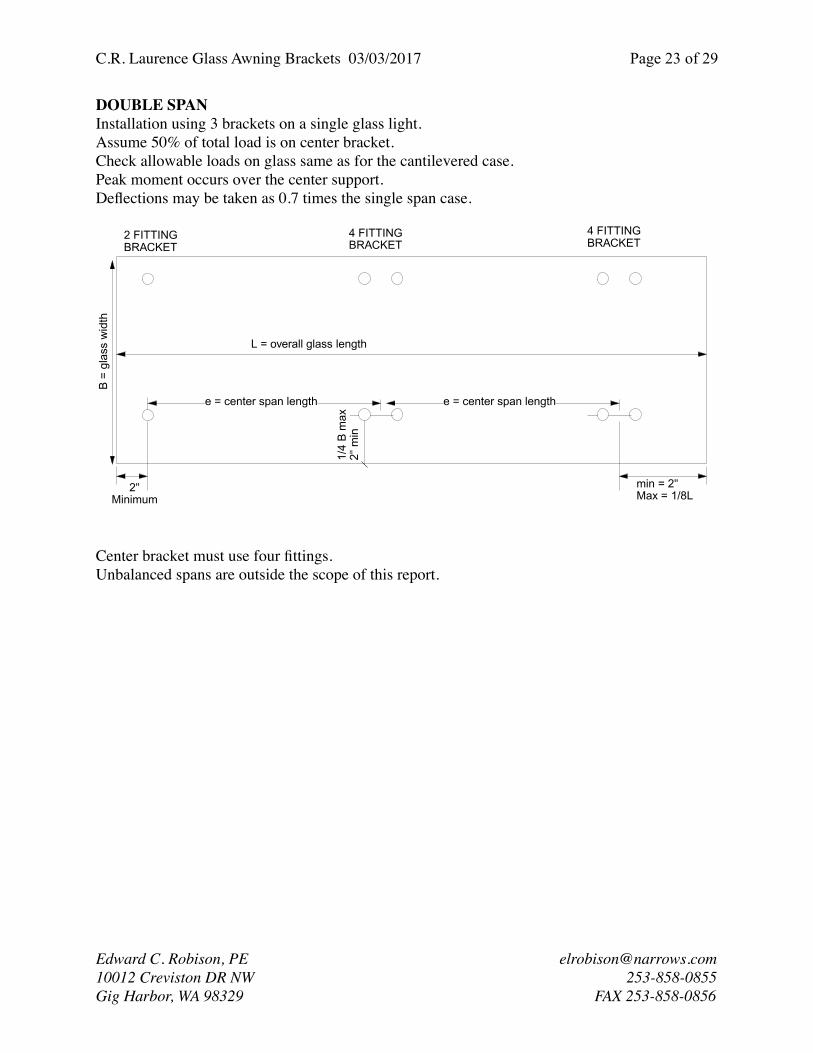
DOUBLE SPANInstallation using 3 brackets on a single glass light.Assume 50% of total load is on center bracket.Check allowable loads on glass same as for the cantilevered case.Peak moment occurs over the center support.Deflections may be taken as 0.7 times the single span case.

Center bracket must use four fittings.Unbalanced spans are outside the scope of this report.

Edward C. Robison, PE [email protected] Creviston DR NW 253-858-0855Gig Harbor, WA 98329 FAX 253-858-0856

e = center span length

L = overall glass length

B =

gla

ss w

idth

1/4

B m

ax2"

min

2 FITTINGBRACKET

4 FITTINGBRACKET

4 FITTINGBRACKET

e = center span length

min = 2"Max = 1/8L

2"Minimum

C.R. Laurence Glass Awning Brackets 03/03/2017 Page ! of !24 29

DERIVATION OF CANTILEVERED SPAN RECOMMENDATIONContour plots below show deflection from 6.5psf dead load on double cantilevered awnings. Blue linear lines represent 0 deflection.

Equations used for calculating deflection are:Mid Deflection = W/(48EI)*(5e4/8-3a2e2/2)-wa2/(24EI)(3e2/4)End Deflection = Wa/(24EI)*(4a2e-e3+3a3)+Wa3/(24EI)*(4e+3a)

Where W is the applied line load, e is support spacing and a is the cantilever length.

Find relationship between e and a. For zero end deflectiona = 0.3091eFor zero mid deflectiona = 0.4545e

For ideal installation for nearly flat glass, average equations to distribute deflection between ends and mid span.a=(0.3091+0.4545)/2*e = 0.3818e

Relate total span (L) to ideal cantilever length (a)a= 0.3818(L-2a)a = 0.2165L

Ideally 56.7% of the total awning length should be between the supports and 21.65% cantilevered past the support on each side for the flattest awning.

Edward C. Robison, PE [email protected] Creviston DR NW 253-858-0855Gig Harbor, WA 98329 FAX 253-858-0856

C.R. Laurence Glass Awning Brackets 03/03/2017 Page ! of !25 29

11/16” GLASSTable

3h1, h2

hv hs;1 hs;2 Is hs Allowable Moment , Mga, (“#/ft)

8mm 0.292 0.06 0.1760 0.0181 0.352

8mm 0.292 0.06 0.1760 0.0181 0.352

Short Dim.

Γ PVB

Γ SGP

hef;w

PVBhef;w

SGPh1;ef;σ

PVBh1;ef;σ

SGPwind PVB

wind SGP

snow PVB

snow SGP

Dead PVB

Dead SGP

24 0.044 0.519 0.390 0.546 0.439 0.585 3807 6749 1760 3120 1269 2249

36 0.094 0.708 0.413 0.588 0.465 0.613 4258 7415 1968 3428 1419 2471

48 0.156 0.812 0.437 0.609 0.491 0.625 4753 7715 2197 3566 1584 2571

54 0.189 0.845 0.450 0.616 0.503 0.629 4997 7803 2310 3607 1665 2601

Glass width B 11/16” Lam.

Temp. Glass

hef;w

PVBhef;w

SGPh1;ef;σ

PVBh1;ef;σ

SGPCantilevered ends under 6” or 1/8th of length

24 0.3900 0.5460 0.4390 0.5850 PVB SGP PVB SGP

eb/e Ce η ∆ d

6.5psfPVB

∆ d6.5psfSGP

σ dead6.5psfPVB

σ dead6.5psfSGP

∆ u20psfPVB

∆ u20psfSGP

σ u20psfPVB

σ u20psf

L/480 L/175

24.0 1.00 0.1606 0.0263 0.0073 0.0027 130 73 0.0224 0.0082 400 225 0.0500 0.1371

36.0 0.67 0.1424 0.1550 0.2175 0.0793 259 146 0.6693 0.2439 798 449 0.0750 0.2057

48.0 0.50 0.1339 0.0140 0.0621 0.0226 434 244 0.1911 0.0696 1334 751 0.1000 0.2743

60.0 0.40 0.1290 0.0134 0.1451 0.0529 653 368 0.4465 0.1627 2008 1131 0.1250 0.3429

72.0 0.33 0.1260 0.0133 0.2986 0.1088 918 517 0.9189 0.3349 2824 1591 0.1500 0.4114

Glass width B 11/16” Lam.

Temp. Glass

hef;w

PVBhef;w

SGPh1;ef;σ

PVBh1;ef;σ

SGPCantilevered ends under 6” or 1/8th of length

36 0.4160 0.5880 0.4650 0.6130 PVB SGP PVB SGP

eb/e Ce η ∆ d

6.5psfPVB

∆ d6.5psfSGP

σ dead6.5psfPVB

σ dead6.5psfSGP

∆ u20psfPVB

∆ u20psfSGP

σ u20psfPVB

σ u20psf

L/480 L/175

36.0 1.00 0.1606 0.0263 0.0304 0.0108 261 150 0.0936 0.0331 802 462 0.0750 0.2057

48.0 0.75 0.1460 0.0167 0.0610 0.0216 421 242 0.1878 0.0665 1296 746 0.1000 0.2743

60.0 0.60 0.1386 0.0148 0.1321 0.0468 625 360 0.4063 0.1439 1923 1107 0.1250 0.3429

72.0 0.50 0.1339 0.0140 0.2590 0.0917 869 500 0.7970 0.2822 2675 1539 0.1500 0.4114

84.0 0.43 0.1310 0.0136 0.4662 0.1651 1158 666 1.4343 0.5079 3562 2050 0.1750 0.4800

Edward C. Robison, PE [email protected] Creviston DR NW 253-858-0855Gig Harbor, WA 98329 FAX 253-858-0856

C.R. Laurence Glass Awning Brackets 03/03/2017 Page ! of !26 29

Glass width B 11/16” Lam.

Temp. Glass

hef;w

PVBhef;w

SGPh1;ef;σ

PVBh1;ef;σ

SGPCantilevered ends under 6” or 1/8th of length

48 0.4370 0.6090 0.4910 0.6250 PVB SGP PVB SGP

eb/e Ce η ∆ d

6.5psfPVB

∆ d6.5psfSGP

σ dead6.5psfPVB

σ dead6.5psfSGP

∆ u20psfPVB

∆ u20psfSGP

σ u20psfPVB

σ u20psf

L/480 L/175

48.0 1.00 0.1606 0.0263 0.0829 0.0306 416 257 0.2551 0.0943 1279 789 0.1000 0.2743

60.0 0.80 0.1486 0.0180 0.1385 0.0512 601 371 0.4263 0.1575 1849 1141 0.1250 0.3429

72.0 0.67 0.1424 0.0155 0.2474 0.0914 829 512 0.7612 0.2812 2552 1575 0.1500 0.4114

78.0 0.62 0.1395 0.0150 0.3297 0.1218 953 588 1.0146 0.3749 2934 1811 0.1625 0.4457

84.0 0.57 0.1374 0.0146 0.4317 0.1595 1089 672 1.3283 0.4908 3351 2068 0.1750 0.4800

Glass width B 11/16” Lam.

Temp. Glass

hef;w

PVBhef;w

SGPh1;ef;σ

PVBh1;ef;σ

SGPCantilevered ends under 6” or 1/8th of length

54 0.4500 0.6160 0.5030 0.6290 PVB SGP PVB SGP

eb/e Ce η ∆ d

6.5psfPVB

∆ d6.5psfSGP

σ dead6.5psfPVB

σ dead6.5psfSGP

∆ u20psfPVB

∆ u20psfSGP

σ u20psfPVB

σ u20psf

L/480 L/175

54.0 1.00 0.1606 0.0263 0.1216 0.0474 501 321 0.3743 0.1459 1542 986 0.1125 0.3086

60.0 0.90 0.1541 0.0218 0.1537 0.0599 594 380 0.4728 0.1843 1827 1168 0.1250 0.3429

66.0 0.82 0.1495 0.0182 0.1878 0.0732 697 446 0.5779 0.2253 2145 1372 0.1375 0.3771

72.0 0.75 0.1460 0.0167 0.2441 0.0952 810 518 0.7511 0.2928 2493 1594 0.1500 0.4114

84.0 0.64 0.1410 0.0151 0.4089 0.1594 1065 681 1.2581 0.4905 3277 2096 0.1750 0.4800

Edward C. Robison, PE [email protected] Creviston DR NW 253-858-0855Gig Harbor, WA 98329 FAX 253-858-0856

C.R. Laurence Glass Awning Brackets 03/03/2017 Page ! of !27 29

13/16” GLASSTable

4h1, h2

hv hs;1 hs;2 Is hs Allowable Moment , Mga, (“#/ft)

10mm 0.355 0.06 0.2075 0.0306 0.415

10mm 0.355 0.06 0.2075 0.0306 0.415

Short Dim.

Γ PVB

Γ SGP

hef;w

PVBhef;w

SGPh1;ef;σ

PVBh1;ef;σ

SGPwind PVB

wind SGP

snow PVB

snow SGP

Dead PVB

Dead SGP

24 0.037 0.470 0.469 0.640 0.527 0.690 5481 9391 2534 4341 1827 3130

36 0.079 0.666 0.491 0.694 0.552 0.727 6019 10427 2783 4820 2006 3475

48 0.132 0.780 0.517 0.722 0.580 0.744 6633 10915 3066 5046 2211 3638

54 0.161 0.818 0.530 0.730 0.593 0.749 6945 11062 3210 5113 2314 3686

Glass width B 13/16” Lam.

Temp. Glass

hef;w

PVBhef;w

SGPh1;ef;σ

PVBh1;ef;σ

SGPCantilevered ends under 6” or 1/8th of length

24 0.4690 0.6400 0.5270 0.6900 PVB SGP PVB SGP

eb/e Ce η ∆ d

6.5psfPVB

∆ d6.5psfSGP

σ dead6.5psfPVB

σ dead6.5psfSGP

∆ u20psfPVB

∆ u20psfSGP

σ u20psfPVB

σ u20psf

L/480 L/175

24.0 1.00 0.1606 0.0263 0.0042 0.0016 90 53 0.0129 0.0051 278 162 0.0500 0.1371

36.0 0.67 0.1424 0.1550 0.1251 0.0492 180 105 0.3849 0.1515 554 323 0.0750 0.2057

48.0 0.50 0.1339 0.0140 0.0357 0.0141 301 175 0.1099 0.0432 926 540 0.1000 0.2743

60.0 0.40 0.1290 0.0134 0.0834 0.0328 453 264 0.2567 0.1010 1393 813 0.1250 0.3429

72.0 0.33 0.1260 0.0133 0.1717 0.0676 637 372 0.5284 0.2079 1960 1143 0.1500 0.4114

Glass width B 13/16” Lam.

Temp. Glass

hef;w

PVBhef;w

SGPh1;ef;σ

PVBh1;ef;σ

SGPCantilevered ends under 6” or 1/8th of length

36 0.4910 0.6940 0.5520 0.7270 PVB SGP PVB SGP

eb/e Ce η ∆ d

6.5psfPVB

∆ d6.5psfSGP

σ dead6.5psfPVB

σ dead6.5psfSGP

∆ u20psfPVB

∆ u20psfSGP

σ u20psfPVB

σ u20psf

L/480 L/175

36.0 1.00 0.1606 0.0263 0.0185 0.0065 185 107 0.0569 0.0202 569 328 0.0750 0.2057

48.0 0.75 0.1460 0.0167 0.0371 0.0131 299 172 0.1142 0.0404 920 530 0.1000 0.2743

60.0 0.60 0.1386 0.0148 0.0803 0.0284 443 256 0.2471 0.0875 1365 787 0.1250 0.3429

72.0 0.50 0.1339 0.0140 0.1575 0.0558 617 356 0.4847 0.1717 1898 1094 0.1500 0.4114

84.0 0.43 0.1310 0.0136 0.2835 0.1004 822 474 0.8723 0.3089 2528 1457 0.1750 0.4800

Edward C. Robison, PE [email protected] Creviston DR NW 253-858-0855Gig Harbor, WA 98329 FAX 253-858-0856

C.R. Laurence Glass Awning Brackets 03/03/2017 Page ! of !28 29

Glass width B 13/16” Lam.

Temp. Glass

hef;w

PVBhef;w

SGPh1;ef;σ

PVBh1;ef;σ

SGPCantilevered ends under 6” or 1/8th of length

48 0.5170 0.7220 0.5800 0.7440 PVB SGP PVB SGP

eb/e Ce η ∆ d

6.5psfPVB

∆ d6.5psfSGP

σ dead6.5psfPVB

σ dead6.5psfSGP

∆ u20psfPVB

∆ u20psfSGP

σ u20psfPVB

σ u20psf

L/480 L/175

48.0 1.00 0.1606 0.0263 0.0501 0.0184 298 181 0.1541 0.0566 917 557 0.1000 0.2743

60.0 0.80 0.1486 0.0180 0.0837 0.0307 431 262 0.2574 0.0945 1325 805 0.1250 0.3429

72.0 0.67 0.1424 0.0155 0.1494 0.0549 594 361 0.4597 0.1688 1829 1111 0.1500 0.4114

78.0 0.62 0.1395 0.0150 0.1991 0.0731 683 415 0.6127 0.2250 2102 1278 0.1625 0.4457

84.0 0.57 0.1374 0.0146 0.2607 0.0957 781 474 0.8022 0.2945 2402 1460 0.1750 0.4800

Glass width B 11/16” Lam.

Temp. Glass

hef;w

PVBhef;w

SGPh1;ef;σ

PVBh1;ef;σ

SGPCantilevered ends under 6” or 1/8th of length

54 0.5300 0.7300 0.5930 0.7490 PVB SGP PVB SGP

eb/e Ce η ∆ d

6.5psfPVB

∆ d6.5psfSGP

σ dead6.5psfPVB

σ dead6.5psfSGP

∆ u20psfPVB

∆ u20psfSGP

σ u20psfPVB

σ u20psf

L/480 L/175

54.0 1.00 0.1606 0.0263 0.0744 0.0285 361 226 0.2291 0.0877 1110 696 0.1125 0.3086

60.0 0.90 0.1541 0.0218 0.0941 0.0360 427 268 0.2894 0.1108 1315 824 0.1250 0.3429

66.0 0.82 0.1495 0.0182 0.1150 0.0440 502 314 0.3537 0.1354 1543 967 0.1375 0.3771

72.0 0.75 0.1460 0.0167 0.1494 0.0572 583 365 0.4597 0.1759 1794 1124 0.1500 0.4114

84.0 0.64 0.1410 0.0151 0.2503 0.0958 766 480 0.7701 0.2947 2358 1478 0.1750 0.4800

Edward C. Robison, PE [email protected] Creviston DR NW 253-858-0855Gig Harbor, WA 98329 FAX 253-858-0856

C.R. Laurence Glass Awning Brackets 03/03/2017 Page ! of !29 29

RB50Ffittings are connected together with 1/4” stainless steel threaded rods.

Vs = 0.65*40.5 ksi*0.049 in2/1.6 = 806#Ts = 0.75*67.5ksi*0.0318 in2/1.6 = 1,006#

Torsion strength of swivel when clamped: = 0.65*1,006#*13/16 = 531”#

Moment strength of swivel:Bending in rod to fixed fitting:rod diameter = 3/8”, A = 0.11 in2

Z = 0.3753/6 = 0.0088 in3

Fb = 65 ksi (longitudinal compression)Mn = 65 ksi*0.0088 in3 = 572#”

Service loads on swivel:Allowable load will be controlled by the bending strength of the connection rod:Ms = 0.9Mn/1.6 = (0.9*572#”/1.6) = 322#”

For lateral loading, M = V*2.25”V = 322#”/2.25 = 143# per swivel

For normal loads, M = H*0.75”H = 322#”/0.75” = 429#

Check strength of fixed bracket to support ( 1/4” threaded rod)Ms = R*Ts = 13/16”*1,006# = 1,584#”

For lateral loading, M = V*2.25”V = 1,584#”/2.25 = 704# per swivel (limited to 143# from connector rod strength)

For normal loads, M = H*2.5”H = 1,584#”/2.5” = 633.6# (limited to 429# by connector rod strength.

Maximum vertical load per fitting = 429#Maximum allowable load on awning:u ≤ 4*429/(B*L) = 1,716/(B*L) for two fittings per bracketu ≤ 8*429/(B*L) = 3,432/(B*L) for two fittings per bracket

For higher loads substitute spider fittings for the RB50F fittings

Edward C. Robison, PE [email protected] Creviston DR NW 253-858-0855Gig Harbor, WA 98329 FAX 253-858-0856


Recommended