13
CS 325: Software Engineering March 3, 2015 Activity Modeling for Transformational Systems • Trtansformational Systems • UML Activity Diagrams
| Date post: | 27-Dec-2015 |
| Category: |
Documents |
| Upload: | charles-barnett |
| View: | 214 times |
| Download: | 1 times |

CS 325: Software Engineering
March 3, 2015
Activity Modeling for Transformational Systems• Trtansformational Systems• UML Activity Diagrams

CS 325March 3, 2015Page 2
Transformational SystemsTransformational systems
consist of a network of information processing activities, each of which transforms its input into its output.
These activities are characterized by control flows that exhibit sequencing, branching, and parallelism, with little or no actor-system interaction.
Consider a compiler, which starts with a lexical analysis process that transforms source code input into a token sequence of identifiers, operators, keywords, etc.Next, a parser takes the token sequence as
input and outputs a syntax tree, which is used as input to a code generator, which outputs executable code.

CS 325March 3, 2015Page 3
UML Activity DiagramsUML Activity
Diagrams model the flow of activity within a process (i.e., within a particular use case).
The Activity Diagram at left illustrates the activities associated with withdrawing money from a bank account at an ATM.

CS 325March 3, 2015Page 4
UML Activity DiagramsConsider an activity diagram
to describe the behavior modeled in the use case diagram below.• The activity is started by a
Commuter actor who needs to buy a ticket.• The ticket vending machine will request trip information from the Commuter.• This information will include the number and type of tickets (e.g., whether it is a monthly pass, one-way or round-trip, the route number, the destination or zone number, etc.).

CS 325March 3, 2015Page 5
UML Activity Diagrams• Based on the provided
trip info, the ticket vending machine will calculate payment due and request payment options (including payment by cash, or by credit or debit card).
• If payment by card is selected by the Commuter, another actor, the Bank will participate in the activity by authorizing the payment.

CS 325March 3, 2015Page 6
UML Activity Diagrams• After payment is
complete, a ticket is dispensed to the Commuter.• Cash payment might result in some change due, so the change is dispensed to the Commuter in this case.• The ticket vending machine will show some "Thank You" screen at the end of the activity.
CS 325March 3, 2015Page 7
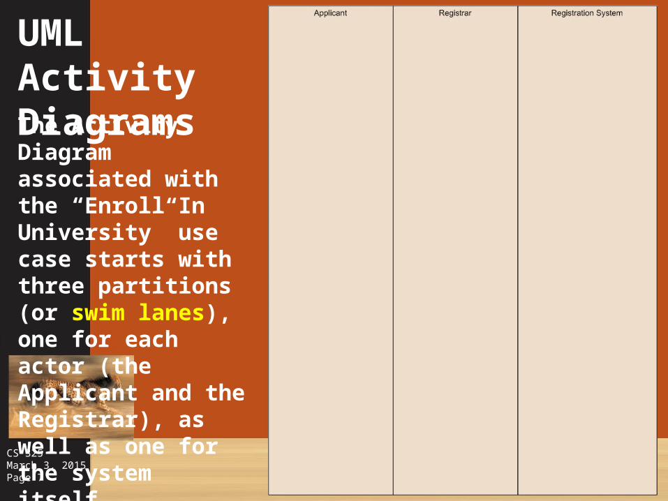
UML Activity DiagramsThe Activity Diagram associated with the “Enroll In University” use case starts with three partitions (or swim lanes), one for each actor (the Applicant and the Registrar), as well as one for the system itself.

CS 325March 3, 2015Page 8
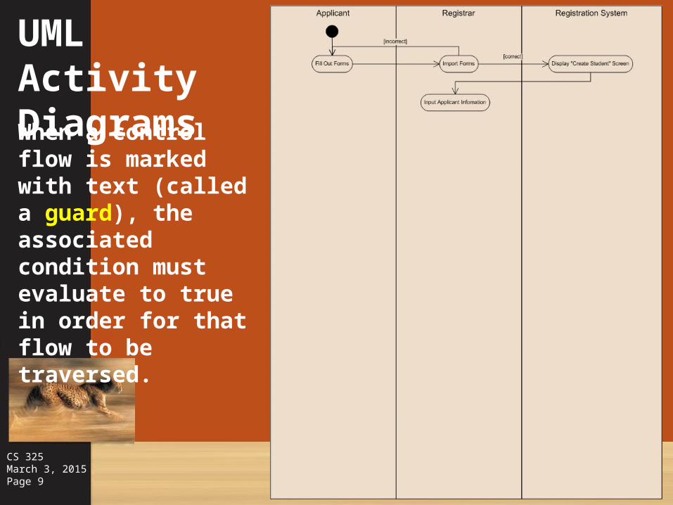
UML Activity DiagramsThe initial state (represented by the large black circle) starts in the swim lane of the actor invoking the use case.Arrows are used to illustrate the control flow, while rounded rectangles represent the actions taken by each actor.
CS 325March 3, 2015Page 9
UML Activity DiagramsWhen a control flow is marked with text (called a guard), the associated condition must evaluate to true in order for that flow to be traversed.

CS 325March 3, 2015Page 10
UML Activity Diagrams
The thick horizontal bar with multiple outgoing flows represents a fork, corresponding to the start of activities taking place in parallel.The circled black circle represents a termination state, a point at which the process ends.

CS 325March 3, 2015Page 11
UML Activity DiagramsA diamond with several entering control flows represents a merge, at which point any of the incoming flows would yield the same outgoing flow.A diamond with several outgoing control flows represents a decision, with conditions indicating which flow will be taken.

CS 325March 3, 2015Page 12
UML Activity DiagramsExplanatory notes may be provided within the diagram to clarify the more complicated aspects of the model.Such notes are particularly helpful to customers and managers, but also assist developers during model reviews.

CS 325March 3, 2015Page 13
UML Activity DiagramsThe thick horizontal bar with multiple incoming flows represents a join, corresponding to the end of activities that were taking place in parallel.


