Manufacturing of Cumene Gharda institute of technology, lavel Page 1 Chapter 1 INTRODUCTION Cumene is the common name for isopropyl benzene, an organic compound that is an aromatic hydrocarbon. It is a constituent of crude oil and refined fuels. It is a flammable colorless liquid that has a boiling point of 152 °C. Nearly all the cumene that is produced as a pure compound on an industrial scale is converted to cumene hydro-peroxide, which is an intermediate in the synthesis of other industrially important chemicals such as phenol and acetone. Cumene (isopropyl benzene) is produced by reacting propylene and benzene over an acid catalyst. Cumene may be used to increase the octane in gasoline, but its primary use is as a feedstock for manufacturing phenol and acetone. The preparation of cumene was first described in 1841 when Gerhardt and Cahours obtained it by distilling cumic acid with lime. The use of aluminium chloride to alkylate benzene was reported by Radziewanowski in 1892. Before the development of the cumene route to phenol and acetone, cumene had been used extensively during World War II as a fuel additive to improve the performance of aircraft piston engines. Like phenol and acetone, α-methylstyrene, diisopropylbenzene, or acetophenone, although these cumene derivative compounds are of considerable commercial importance. Currently, over 80% of all cumene is produced by using zeolite based processes. Early processes using zeolite based catalyst system were developed in the late 1980s. [9]
Transcript
Manufacturing of Cumene
Gharda institute of technology, lavel Page 1
Chapter 1
INTRODUCTION
Cumene is the common name for isopropyl benzene, an organic compound that is an
aromatic hydrocarbon. It is a constituent of crude oil and refined fuels. It is a flammable
colorless liquid that has a boiling point of 152 °C. Nearly all the cumene that is produced as a
pure compound on an industrial scale is converted to cumene hydro-peroxide, which is an
intermediate in the synthesis of other industrially important chemicals such as phenol and
acetone.
Cumene (isopropyl benzene) is produced by reacting propylene and benzene over an
acid catalyst. Cumene may be used to increase the octane in gasoline, but its primary use is as a
feedstock for manufacturing phenol and acetone. The preparation of cumene was first described
in 1841 when Gerhardt and Cahours obtained it by distilling cumic acid with lime. The use of
aluminium chloride to alkylate benzene was reported by Radziewanowski in 1892. Before the
development of the cumene route to phenol and acetone, cumene had been used extensively
during World War II as a fuel additive to improve the performance of aircraft piston engines.
Like phenol and acetone, α-methylstyrene, diisopropylbenzene, or acetophenone, although these
cumene derivative compounds are of considerable commercial importance. Currently, over 80%
of all cumene is produced by using zeolite based processes. Early processes using zeolite based
catalyst system were developed in the late 1980s.[9]
Manufacturing of Cumene
Gharda institute of technology, lavel Page 2
Chapter 2
PROPERTIES
Cumene is colorless liquid soluble in alcohol, carbon tetra chloride, ether and benzene. It
is insoluble in water.
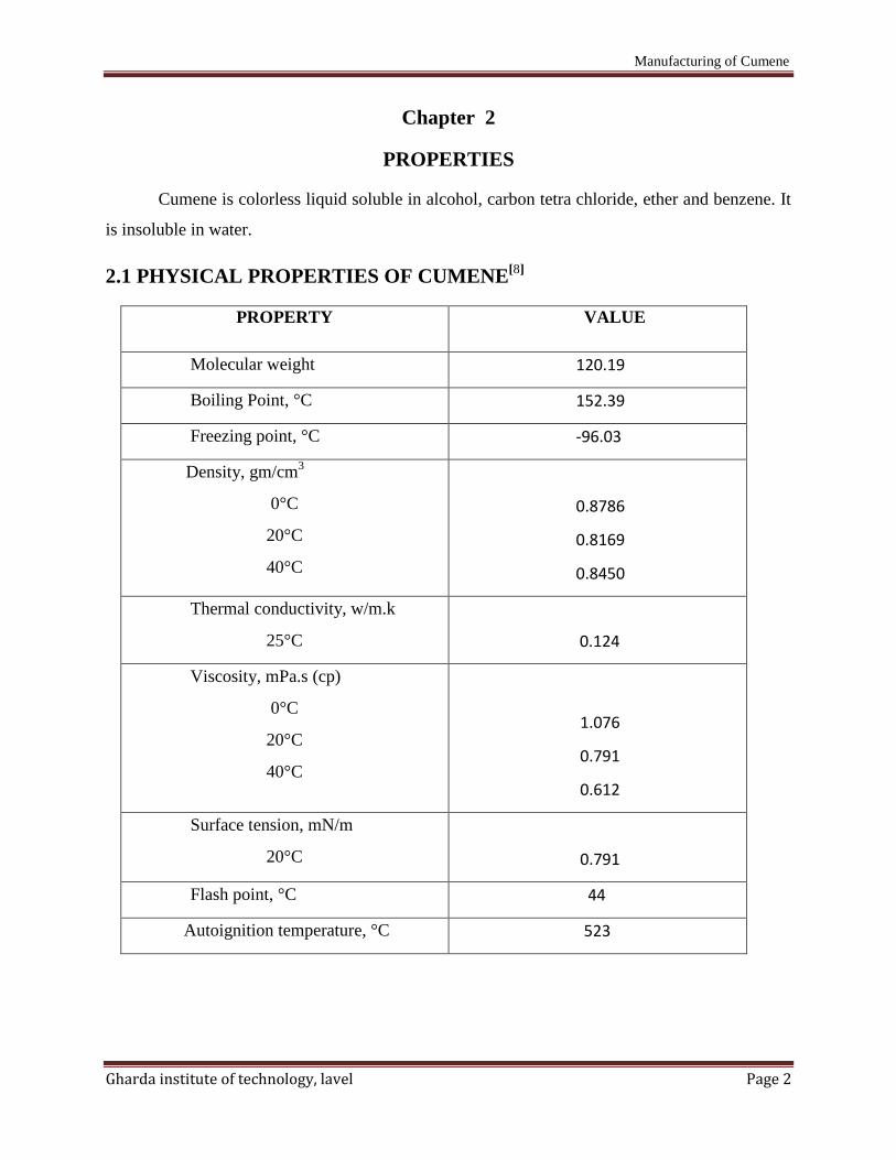
2.1 PHYSICAL PROPERTIES OF CUMENE[8]
PROPERTY VALUE
Molecular weight 120.19
Boiling Point, °C 152.39
Freezing point, °C -96.03
Density, gm/cm3
0°C
20°C
40°C
0.8786
0.8169
0.8450
Thermal conductivity, w/m.k
25°C
0.124
Viscosity, mPa.s (cp)
0°C
20°C
40°C
1.076
0.791
0.612
Surface tension, mN/m
20°C
0.791
Flash point, °C 44
Autoignition temperature, °C 523
Manufacturing of Cumene
Gharda institute of technology, lavel Page 3
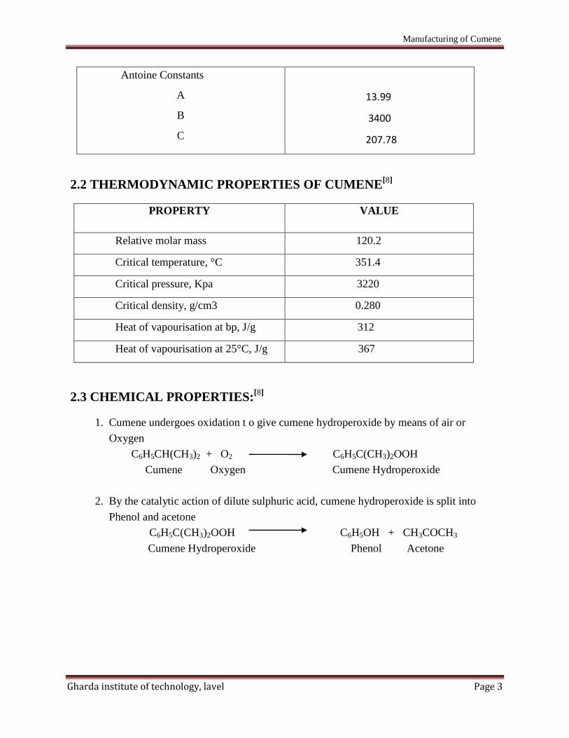
Antoine Constants
A
B
C
13.99
3400
207.78
2.2 THERMODYNAMIC PROPERTIES OF CUMENE[8]
PROPERTY VALUE
Relative molar mass 120.2
Critical temperature, °C 351.4
Critical pressure, Kpa 3220
Critical density, g/cm3 0.280
Heat of vapourisation at bp, J/g 312
Heat of vapourisation at 25°C, J/g 367
2.3 CHEMICAL PROPERTIES:[8]
1. Cumene undergoes oxidation t o give cumene hydroperoxide by means of air or
Oxygen
C6H5CH(CH3)2 + O2 C6H5C(CH3)2OOH
Cumene Oxygen Cumene Hydroperoxide
2. By the catalytic action of dilute sulphuric acid, cumene hydroperoxide is split into
Phenol and acetone
C6H5C(CH3)2OOH C6H5OH + CH3COCH3
Cumene Hydroperoxide Phenol Acetone
Manufacturing of Cumene
Gharda institute of technology, lavel Page 4
Chapter 3
USES
Cumene is used[2]
1. As feedback for the production of Phenol and its co-product acetone
2. The cumene oxidation process for phenol synthesis has been growing in popularity
Since the 1960’s and is prominent today. The first step of this process is the formation
of cumene hydroperoxide. The hydroperoxide is then selectively cleaved to Phenol
and acetone.
3. Phenol in its various for maldehyde resins to bond construction materials like plywood
and composition board (40% o f the phenol produced) for the bisphenol. A employed
in making epoxy resins and polycarbonate (30%) and for caprolactum, the starting
material for nylon-6 (20%). Minor amounts are used for alkylphenols and
pharmaceuticals.
4. The largest use for acetone is in solvents although increasing amounts are used to
make bisphenol A and methylacrylate.
5. Methylstyrene is produced in controlled quantities from the cleavage of cumene
Hydroperoxide or it can be made directly by the dehydrogenation o f cumene.
6. Cumene in minor amounts is used as a thinner for paints, enamels and lacquers and to
produce acetophenone, the chemical intermediate dicumylperoxide and diisopropyl
benzene.
7. Cumene is also used as a solvent for fats and raisins.
Manufacturing of Cumene
Gharda institute of technology, lavel Page 5
Chapter 4
MANUFACTURING PROCESSES OF CUMENE.
There are four types of manufacturing process of cumene.
1. Liquid phase alkylation using Phosphoric acid.
2. Liquid phase alkylation using Aluminium chloride.
3. Q-Max process.
4. CD-Cumene process.
4.1 LIQUID PHASE ALKYLATION USING PHOSPHORIC ACID [2]
4.1.1 INTRODUCTION
SPA (Solid phosphoric acid) remains a viable catalyst for cumene syenthesis. In recent
years , producers have been given increasing incentives for better cumene product quality of the
phenol, acetone, and especially alpha-methyl styrene produced from the downstream phenol
units.
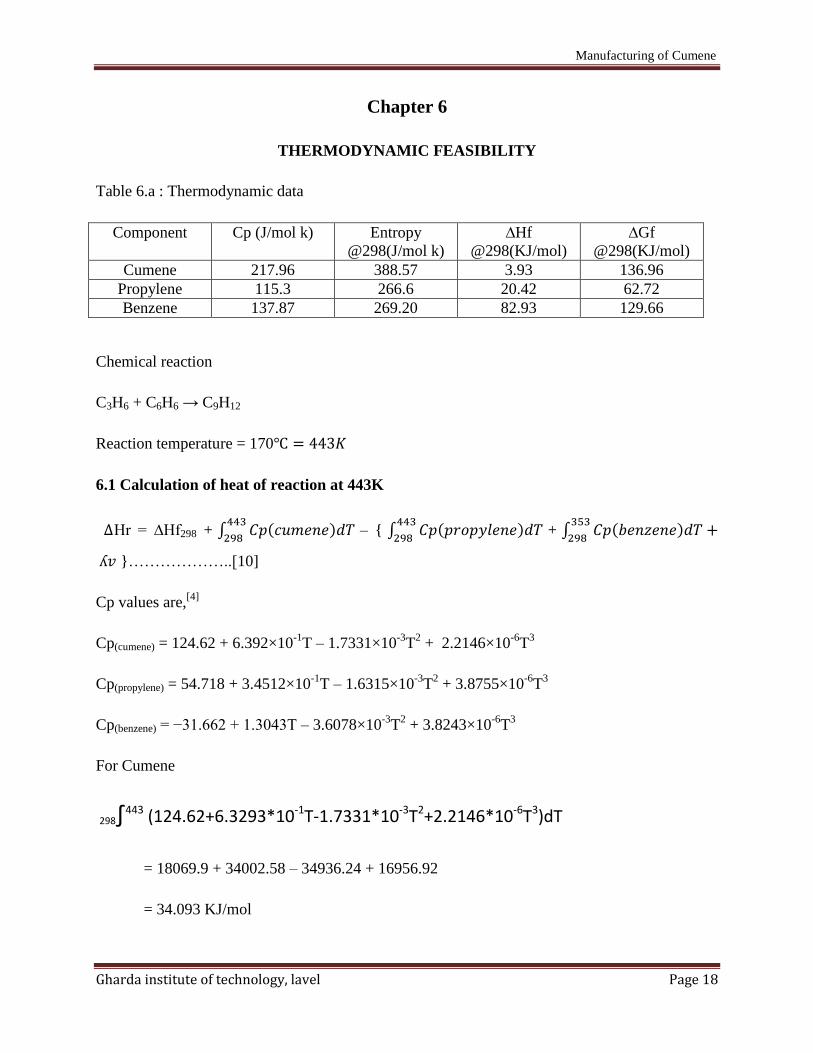
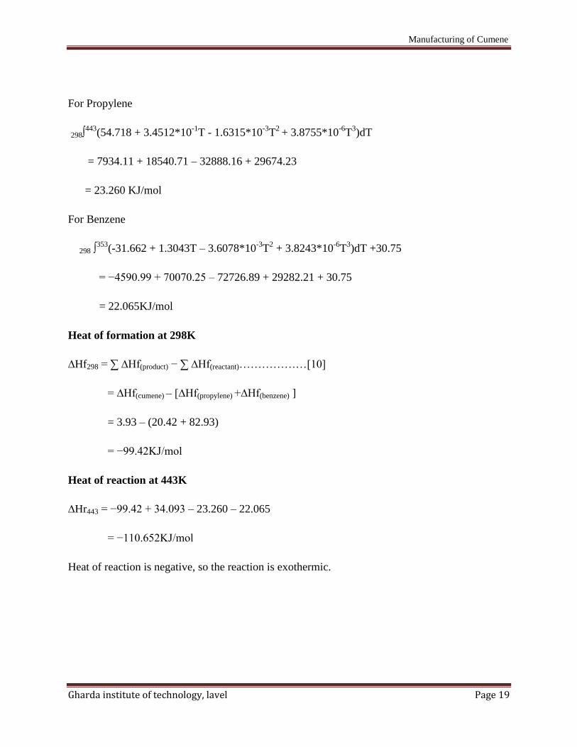
4.1.2 CHEMICAL REACTION
Main Reaction
C6H6 + CH3.CH=CH2 C6H5. C3H7 ;
Side Reaction
C6 H6 + nCH3CH=CH2 C6 H6-n.(CH)n
4.1.3 PROCESS DESCRIPTION
Propylene-propane feedstock from refinery off gases from a naphtha steam cracking
plant and recycle benzene is mixed with benzene are charged upflow into fixed bed reactor,
which operates at 3-4 MPa and at 200-260 C and pumped at 25 atms. Into the top of a reactor
packed stage wise with H3PO4 impregnated catalyst. The SPA catalyst provides an essentially
complete conversion of propylene on a one pass basis. The temperature is maintained at
approximately 250 C by adding cold propane at each stage to absorb heat of reaction.
The reactor effluent is depropanized and the propane split into quench or product streams.
The propanized bottoms are separated into benzene, cumene,and polycumenes in the remaining
Jie_Sheng
Highlight
Manufacturing of Cumene
Gharda institute of technology, lavel Page 6
two stills. A typical reactor effluent stream contain 94.8 wt% cumene and 3.1 wt%
diisopropylbenzene (DIPB). The remaining 2.1% is primarily heavy aromatics. This high yield
of cumene is achieved without transalkylation of DIPB is the key advantage of SPA catalyst
process. The cumene product is 99.9 wt% pure. The heave aromatics which have research octane
no (RON) of about 109 can be either used as high octane gasoline blending components or
combined with additional benzene and sent to transalkylation section of the plant where DIPB is
converted to cumene. The overall yield of cumene for this process based on benzene and
propylene is typically 97-98 wt% if transalkylation is included or 94-96 wt% without
transalkylation
Manufacturing of Cumene
Gharda institute of technology, lavel Page 7
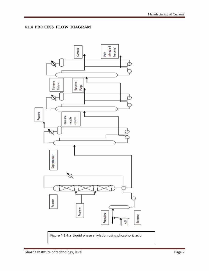
4.1.4 PROCESS FLOW DIAGRAM
Figure 4.1.4.a Liquid phase alkylation using phosphoric acid
Manufacturing of Cumene
Gharda institute of technology, lavel Page 8
4.2 LIQUID PHASE ALKYLATION USING AlCl3 [2]
4.2.1 INTRODUCTION
Aluminium chloride is a preferred alkylating agent for the production of cumene.
Basically the design is same to that described for other processes, having pretreatment section if
required, a reactor section and a distillation section. The reaction conditions, including
arrangement for the feeding catalyst and recycle of polyalkylbenzenes for dealkylation are
however quite different.
4.2.2 PROCESS DESCRIPTION-
If feed treatment is required depending on the quality of feedstock, propylene is dried in a
regenerative absorptive drier and fed to de-ethanizer where c2 compounds are distilled. The
bottoms pass to a propylene column where c4’s and heavier are removed in the base stream.
Liquid propylene in the overheads is vaporized and fed to the reactor. Fresh benzene contains too
much water for immediate addition to the reactors, is mixed with recycle benzene and fed to
column. After condensation, benzene and water separate in a decanter. Benzene from the base
contains less than 10ppm water.
The reaction section usually consists of two or more brick lined vessels partitioned into
reaction and settling zones with downstream separators and wash drums. All the reactants and
recycle streams are introduced into the reaction zone. Since agitation is required, propylene
vapours are admitted at the base where catalyst complex, which is insoluble in a hydrocarbon,
tends to settle. The complex is hereby lifted and mixed intimately with the reactants. Aluminium
chloride is added to the top of the reactor and the promoter usually HCl or isopropyl enters with
the reactant. The promoter is essential for stabilizing the catalyst complex, for only a stable
complex will catalyze the reaction. In addition to the gaseous feed to distribute the catalyst
complex, there may be provided a pump to recirculate settled complex to the top of the reaction
zone and a compressor to recycle propane. The distillation section consist of ethylbenzene unit
have been constructed where the catalyst complex is prepared in a separate vessel. Care has to be
taken with the reactor off gases which in addition to benzene and other light hydrocarbons
contains HCl. The benzene is recovered in an absorber containing recycling PAB and the HCl is
scrubbed out of the off- gas in two towers, one containing water and the other containing caustic
Manufacturing of Cumene
Gharda institute of technology, lavel Page 9
soda solution. The residual gas can be compressed and used as fuel. The material heavier than
cumene is not disposed of as fuel, is returned to the reactors for transalkylation after removing
the heaviest polyalkylbenzenes. The later operation is conducted in a small column under high
vacuum.
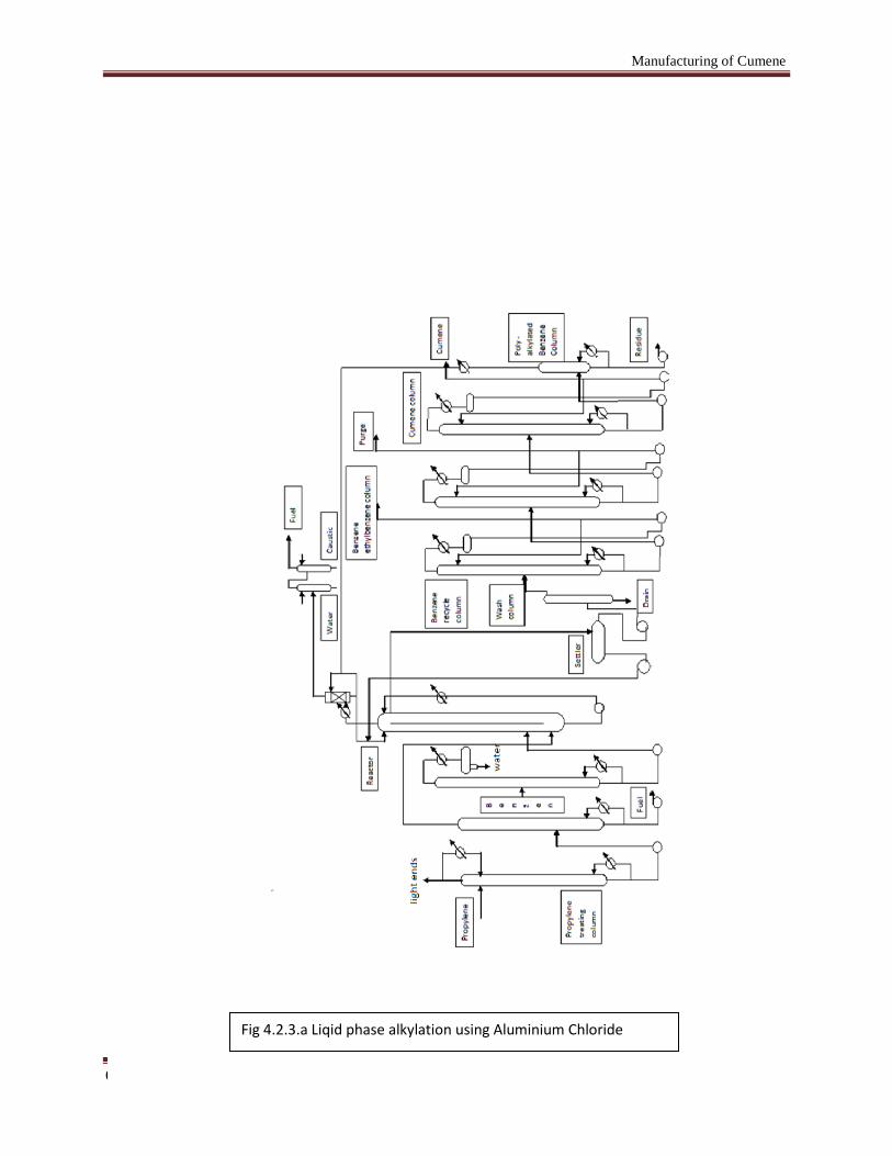
4.2.3 PROCESS FLOW DIAGRAM
Manufacturing of Cumene
Gharda institute of technology, lavel Page 10
Fig 4.2.3.a Liqid phase alkylation using Aluminium Chloride
Manufacturing of Cumene
Gharda institute of technology, lavel Page 11
4.3 Q-MAX PROCESS[1,5,6]
4.3.1 INTRODUCTION
The Q- Max process is based on liquid phase process. The Q-Max process produces
nearly equilibrium levels of cumene between 85 to 95 mole% and DIPB between 5 and 15
mole%. The Q-Max process had selected most promising catalyst based on beta zeolite for
cumene production.
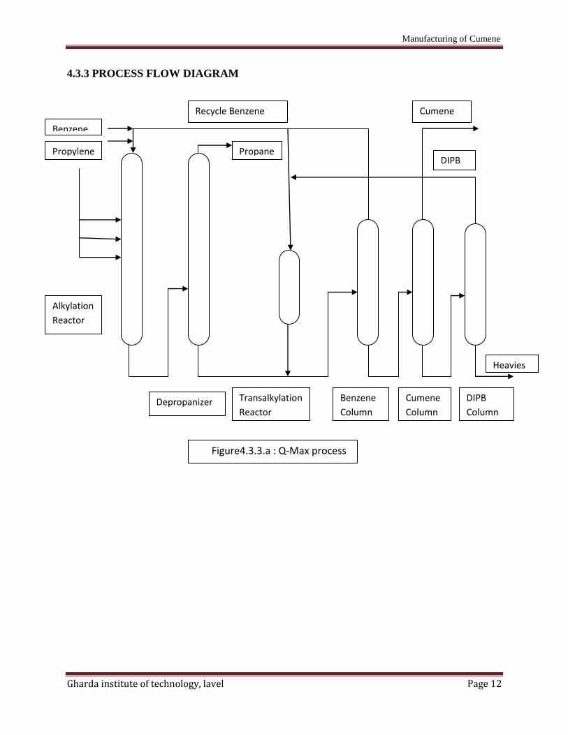
4.3.2 PROCESS DESCRIPTION
A Q-max unit consists of an alkylation reactor, a distillation section, and a transalkylation
reactor. Both reactors are fixed bed. The alkylation reactor is divided into four catalyst beds
contained in a single reactor vessel. Propylene and a mixture of fresh and recycle benzene are
charged to the alkylation reactor, where the propylene reacts to completion to form mainly
cumene. Effluent from the alkylation reactor is sent to the depropanized column, which removes
the propane that entered the unit with the propylene feed, along with any excess water which
may have accompanied the feeds. The Depropanizer column bottoms is sent to the benzene
column where benzene is collected overhead and recycled. Benzene column bottom is sent to the
cumene column where cumene product is recovered overhead. The bottom from the cumene
column, containing mostly diisopropylbenzene is sent to the DIPB column where DIPB is
recovered and recycled to the transalkylation reactor. The bottoms from the DIPB column consist
of a small stream of heavy aromatic by-product which are normally used as high octane gasoline
blending component.
The catalyst in both the alkylation and transalkylation reactors is regenerable. The typical
design cycle length between regenerations is 2years, but the unit can be designed for somewhat
longer cycles if desired. Ultimate catalyst life is at least three cycle. Mild operating conditions
and a corrosion free process environment permit the use of carbon steel construction and
conventional process equipment.
Manufacturing of Cumene
Gharda institute of technology, lavel Page 12
4.3.3 PROCESS FLOW DIAGRAM
Recycle Benzene
Benzene
Propylene
Cumene
DIPB
Heavies
DIPB
Column
Cumene
Column
Benzene
Column
Transalkylation
Reactor Depropanizer
Alkylation
Reactor
Propane
Figure4.3.3.a : Q-Max process
Manufacturing of Cumene
Gharda institute of technology, lavel Page 13
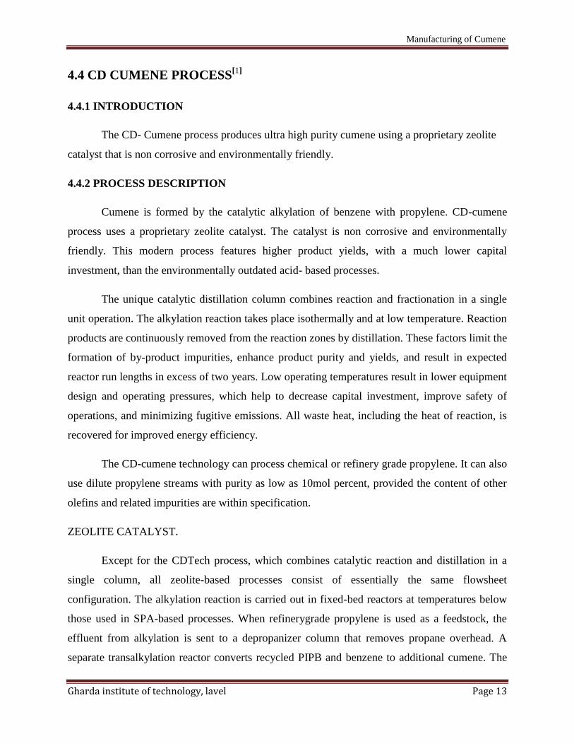
4.4 CD CUMENE PROCESS[1]
4.4.1 INTRODUCTION
The CD- Cumene process produces ultra high purity cumene using a proprietary zeolite
catalyst that is non corrosive and environmentally friendly.
4.4.2 PROCESS DESCRIPTION
Cumene is formed by the catalytic alkylation of benzene with propylene. CD-cumene
process uses a proprietary zeolite catalyst. The catalyst is non corrosive and environmentally
friendly. This modern process features higher product yields, with a much lower capital
investment, than the environmentally outdated acid- based processes.
The unique catalytic distillation column combines reaction and fractionation in a single
unit operation. The alkylation reaction takes place isothermally and at low temperature. Reaction
products are continuously removed from the reaction zones by distillation. These factors limit the
formation of by-product impurities, enhance product purity and yields, and result in expected
reactor run lengths in excess of two years. Low operating temperatures result in lower equipment
design and operating pressures, which help to decrease capital investment, improve safety of
operations, and minimizing fugitive emissions. All waste heat, including the heat of reaction, is
recovered for improved energy efficiency.
The CD-cumene technology can process chemical or refinery grade propylene. It can also
use dilute propylene streams with purity as low as 10mol percent, provided the content of other
olefins and related impurities are within specification.
ZEOLITE CATALYST.
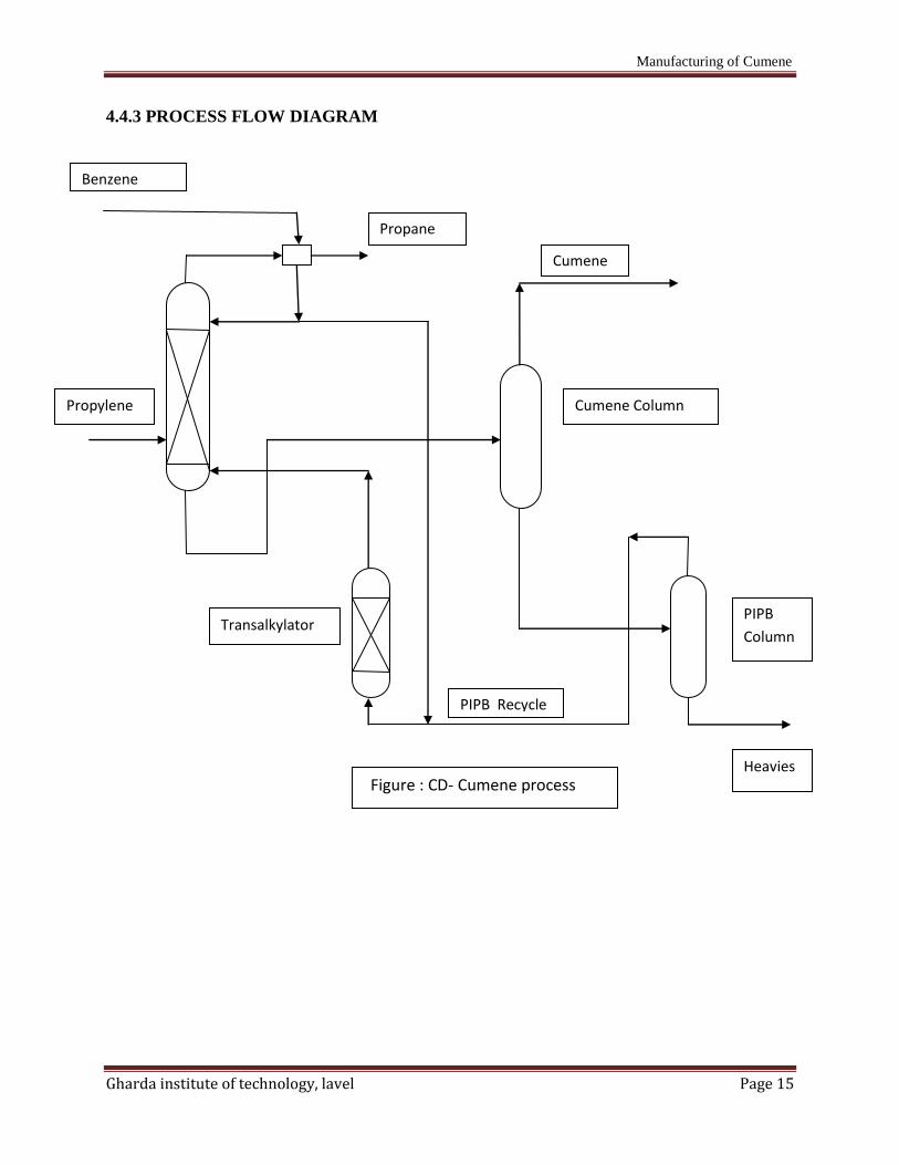
Except for the CDTech process, which combines catalytic reaction and distillation in a
single column, all zeolite-based processes consist of essentially the same flowsheet
configuration. The alkylation reaction is carried out in fixed-bed reactors at temperatures below
those used in SPA-based processes. When refinerygrade propylene is used as a feedstock, the
effluent from alkylation is sent to a depropanizer column that removes propane overhead. A
separate transalkylation reactor converts recycled PIPB and benzene to additional cumene. The
Manufacturing of Cumene
Gharda institute of technology, lavel Page 14
bottoms of the depropanizer are then mixed with the transalkylation reactor effluent and fed to a
series of three distillation columns. Benzene, product cumene, and PIPB are respectively
separated in the overhead of each column, with PIPB and benzene recycled to the reaction
system. A small stream of heavy aromatics is separated in the bottoms of the PIPB column. Like
the AlCl3 catalyst, zeolites are sufficiently active to transalkylate PIPB back to cumene. Overall
selectivity of benzene to cumene is quite high, varying from 99.7% to almost stoichiometric,
depending on the nature of the zeolite employed. Product purities as high as 99.97% can be
obtained, with B/P feed ratios between 3 and 5. A particular advantage of the zeolite catalysts is
that they are regenerable and can be used for several cycles. Therefore, the waste disposal
problems associated with SPA and AlCl3 catalysts are greatly reduced. In addition, carbon steel
can be used as the material of construction throughout the plant because of the mild operating
conditions and the absence of highly corrosive compounds. One limitation of the zeolite
technology is potential poisoning of the catalyst by contaminants in the feed.
Depending on feedstock quality, guard beds or additional feed pretreatment may thus be
required. If refinerygrade propylene is used, for example, its sulfur content must be closely
controlled.
Manufacturing of Cumene
Gharda institute of technology, lavel Page 15
4.4.3 PROCESS FLOW DIAGRAM
PIPB Recycle
Cumene
Cumene Column
PIPB
Column
Heavies
Propane
Benzene
Propylene
Figure : CD- Cumene process
Transalkylator
Manufacturing of Cumene
Gharda institute of technology, lavel Page 16
Chapter 5
SELECTION OF PROCESS
5.1 ADVANTAGES
5.1.1 LIQUID PHASE ALKYLATION USING PHOSPHORIC ACID[2]
a) The SPA catalyst provides an essentially complete conversion of propylene on a one
pass basis.
b) Cumene product 99.9 wt% pure.
c) By product removal is relatively simple.
5.1.2 LIQUID PHASE ALKYLATION USING AlCl3[2]
a) Propane in propylene feed is recovered as liquid petroleum gas(LPG)
b) By product removal is relatively simple.
c) PAB may be recycled to the reactor as aluminium chloride has ability to
transalkylated PAB in presence of benzene.
5.1.3 Q-MAX PROCESS[1]
a) The catalyst in the both alkylation and Transalkylation reactor are regenerable.
b) The expected catalyst cycle is 2-4 years and the catalyst should not need replacement
for at least 3 cycles.
c) The Q-Max requires minimum pretreatment of feeds, which further minimizes the
capital costs.
5.1.4 CD- CUMENE PROCESS[1]
a) High selectivity and lower by product formation. High product yield; reduced plot
area.
b) Lower maintenance cost.
c) Decrease capital investment; improve safety and operability; applicable to conversion
of existing cumene plants.
d) Reduces utilities and operating cost; recover all waste heat and heat of reactions.
Manufacturing of Cumene
Gharda institute of technology, lavel Page 17
e) Improves economics – plant can be custom designed to process specific feed stocks
including the less expensive feedstock.
f) Continuous process.
g) Meets evolving environmental requirements.
h) Catalytic reaction and distillation is done in single column.
5.2 DISADVANTAGES
5.2.1 LIQUID PHASE ALKYLATION USING PHOSPHORIC ACID[2]
:
a) Cumene yield is limited to 95% because of the oligomerization of propylene and the
formation of heavy alykalate by-products.
b) The process requires a relatively high benzene propylene molar feed ratio on the
order of 7/1 to maintain cumene yield.
c) The catalyst is not regenerable and must be disposed at the end of each short catalyst
cycle.
5.2.2 LIQUID PHASE ALKYLATION USING ALUMINIUM CHLORIDE[2]
:
a) Feed pretreatment is required.
b) The presence of HCL in and around the reaction area can be troublesome; its
treatment is the major disadvantage of this process.
Q-Max Process and CD-Cumene process doesn’t have any disadvantage. But from
this two processes CD-Cumene process is more effective than Q-max process because,
a) Extends reactor run length over one year without regeneration, sustain high
conversion and selectivity.
b) Decrease capital investment, improves safety and operability.
c) Reduces utilities and operating costs, recovers all waste heat and heat of reaction.
d) Improves economics- plans can be custom designed to process specific feedstocks
including less expensive feedstock.
So that we are selecting CD-cumene process of manufacturing of CUMENE.