University of Pisa Department of Energy and Systems Engineering Novel Haptic Cueing for UAV Tele-Operation Thesis Ph.D Course on: Automation Robotics and Bioengineering Cicle XXII (2007) Tutor: Prof. Lorenzo Pollini Student: Samantha M.C. Alaimo
Transcript
University of Pisa
Department of Energy and Systems Engineering
Novel Haptic Cueing
for UAV Tele-Operation
ThesisPh.D Course on:
Automation Robotics and BioengineeringCicle XXII (2007)
Tutor:Prof. Lorenzo PolliniStudent:Samantha M.C. Alaimo
ii
Typeset by the author with the LATEX Documentation System.Author email: [email protected]
Abstract
The use of Unmanned Aerial Vehicles (UAVs) is continuously in-creasing both for military and civilian operations. The degree ofautomation inside an UAV has reached the capability of high lev-els of autonomy, increasing but human participation/action is stilla requirement to ensure an ultimate level of safety for the mission.Direct remote piloting is often required for a board range of situ-ations; this is true especially for larger UAVs, where a fault mightbe dangerous for the platform but even for the other entities of itsenvironment (people, building etc.). Unfortunately the physical sep-aration between pilot/operator and the UAV reduces greatly thesituational awareness; this has a negative impact on system per-formance in the presence of remote and unforeseen environmentalconstraints and disturbances. This is why this thesis is dedicated tothe study of means to increase the level of situational awareness ofthe UAV operator.
The sense of telepresence is very important in teleoperation, andit appears reasonable, and it has already been shown in the litera-ture, that extending the visual feedback with force feedback is ableto complement the visual information (when missing or limited). Anartificially recreated sense of touch (haptic) may allow the operatorto better perceive information from the remote aircraft state, theenvironment and its constraints, hopefully preventing dangerous sit-uations. This thesis introdues first a novel classification for hapticaid systems in two large classes: Direct Haptic Aid (DHA) and Indi-
iii
iv
rect Haptic Aid (IHA), then, after showing that almost all existingaid concepts belong to the first class, focuses on IHA and tries toshow that classical applications (that used a DHA approach) can berevised in a IHA fashion. The novel IHA systems produce differ-ent sensations, which in most cases may appear as exactly ”oppositein sign” from the corresponding DHA; these sensations can providevaluable cues for the pilot, both in terms of improvement of perfor-mance and ”level of appreciation”. Furthermore, it will be shownthat the novel cueing algorithms, which were designed just to appear”natural” to the operator, and not to directly help the pilot in histask (as in the DHA cases), can outperform the corresponding DHAsystems.
Three case studies were selected: obstacle avoidance, wind gustrejection, and a combination of the two. For all the cases, DHA andIHA systems were designed and compared against baseline perfor-mance with no haptic aid. Test results show that a net improvementin terms of performance is provided by employing the IHA cuse in-stead of both the DHA cues or the visual cues only. Both professionalpilots and nave subjects were used in some of the experiments. Theperceived feelings transmitted by the haptic cues, strongly dependby the type of the experiment and the quality of the participants: theprofessional pilots, for instance, retained the DHA the most helpfulforce while they preferred IHA because they found it more natu-ral and because they felt a better control authority on the aircraft;different results were obtained with naive participants.
In the end, this thesis aim is to show that the IHA philosophy isa valid and promising alternative to the other commonly used, andpublished in the scientific literature, approaches which fall in theDHA category.
Finally the haptic cueing for the obstacle avoidance task wastested in the presence of time delay in the communication link, as ina classical bilateral teleoperation scheme. The Master was providewith an admittance controller and an observer for force exerted by
v
the human on the stick was developed. Experiments have shownthat the proposed system is capable of standing substantial commu-nication delays.
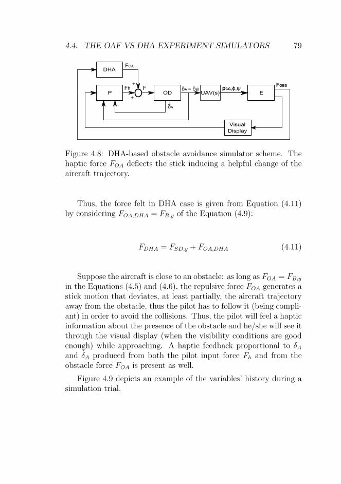
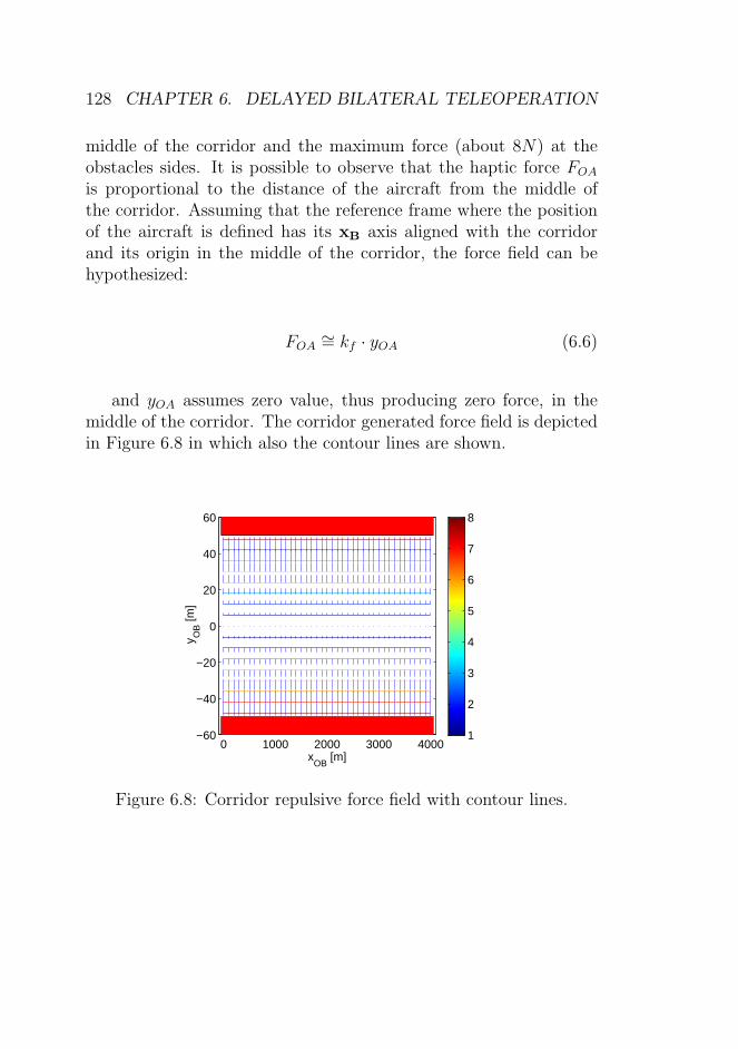
4.10 IHA-OAF simulator scheme. The haptic force FOA
deflects the stick without producing any change to theaircraft trajectory thanks to the effect of the compen-sating signal δOA. . . . . . . . . . . . . . . . . . . . . 82
4.12 Isolated obstacle scenario: IHA, DHA and NoEF ex-periments in the Maximum Fog visibility condition.The obstacle is drawn in red. The lines represent: theaircraft trajectory (blue) starting from the left, theforce FWG (green when present) and the total forceFy (magenta). . . . . . . . . . . . . . . . . . . . . . . 85
LIST OF FIGURES xiii
4.13 Out of the window view from the same viewpointwhile the same obstacle, in the left side, is approach-ing under the three different visibility conditions: a)Minimum Fog ; b) Medium Fog ; c) Maximum Fog. . . 86
4.14 Performance (mean and standard deviation) for the3 Force conditions (DHA, IHA-OAF, NoEF) and forthe 3 visibility conditions (A, B, C). . . . . . . . . . . 88
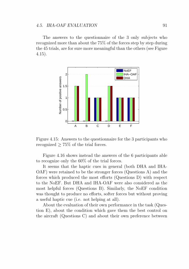
4.15 Answers to the questionnaire for the 3 participantswho recognized ≥ 75% of the trial forces. . . . . . . . 91
4.16 Participants answers to questionnaire for the 6 par-ticipants who recognized ≥ 60% of the trial forces. . . 92
5.1 The interaction between the wind and the urban canyon:a) the wake effect, b) the tunnel effect. . . . . . . . . 94
5.2 The wind gust implementation in the aircraft dynamics. 96
5.4 NoEF simulation example. The blue, the green andthe magenta lines (the last two are superimposed andconstantly null) represent respectively the aircraft tra-jectory, the obstacle avoidance force (FOA) and thewind gust rejection force (FWG). . . . . . . . . . . . . 103
5.5 DHA-based obstacle avoidance in the presence of lat-eral wind gusts simulator scheme. The haptic forcesFOA and FWG deflect the stick inducing a helpfulchange of the aircraft trajectory. . . . . . . . . . . . . 104
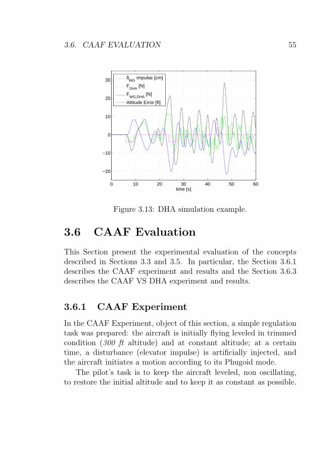
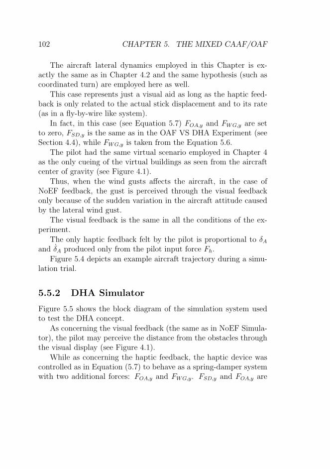
5.6 DHA simulation example. The blue, the green andthe magenta lines represent respectively the aircrafttrajectory, the obstacle avoidance force (FOA) and thewind gust rejection force (FWG). . . . . . . . . . . . . 105
xiv LIST OF FIGURES
5.7 IHA-Mixed CAAF/OAF simulator scheme. The hap-tic forces FOA and FWG deflect the stick without pro-ducing any change to the aircraft trajectory thanks tothe effect of the compensating signal δOA. . . . . . . . 106
5.8 IHA-Mixed CAAF/OAF simulation example. Theblue, the green and the magenta lines (the last two aresuperimposed and constantly null) represents respec-tively the aircraft trajectory, the obstacle avoidanceforce (FOA) and the wind gust rejection force (FWG). 107
5.9 Performance (mean and standard error) for the twoWind conditions (No Wind and Wind), for the 3 Forceconditions (DHA=2, IHA-Mixed CAAF/OAF=1, NoEF=0)and for the 2 visibility conditions (A, B). . . . . . . . 111
5.10 Answers to questionnaire for the 2 participants whorecognized ≥ 70% of the trial forces. . . . . . . . . . 113
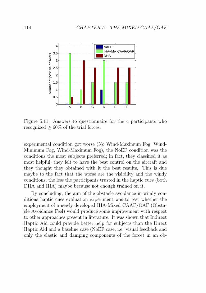
5.11 Answers to questionnaire for the 4 participants whorecognized ≥ 60% of the trial forces. . . . . . . . . . 114
6.1 The teleoperation system (picture from http://www.flickr.com).The red arrow represents the force feedback on thecontrol device. . . . . . . . . . . . . . . . . . . . . . . 119
6.10 Bode plot of the compensator C(s). . . . . . . . . . . 131
LIST OF FIGURES xv
6.11 Fh and Fk time response when K(s) = 0.2. . . . . . . 132
6.12 Fh and Fk time response when K(s) = 0.1, 0.5, 0.9respectively. . . . . . . . . . . . . . . . . . . . . . . . 133
6.13 Fh and Fk time response when K(s) = 50%C(s). . . . 134
6.14 Path comparison (Figure 6.2 scheme) with and with-out time delay by using: a) the Omega Device model;b) the real Omega Device and the pilot out of the loop.135
6.15 Path comparison (Figure 6.2) with and without timedelay and the human operator in the loop. a) FOA =0; b) FOA 6= 0. . . . . . . . . . . . . . . . . . . . . . . 136
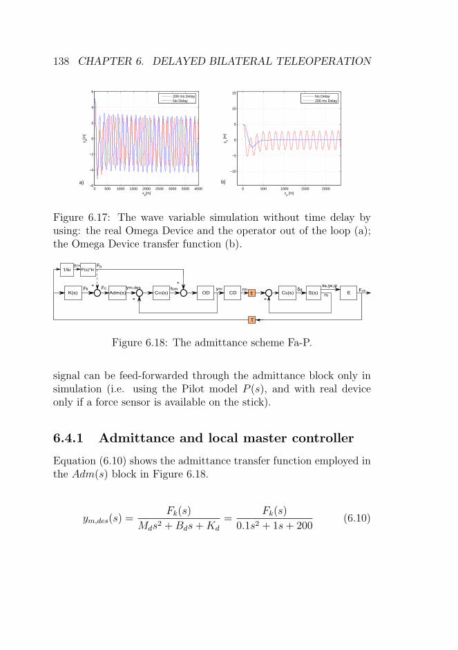
6.17 The wave variable simulation without time delay byusing: the real Omega Device and the operator out ofthe loop (a); the Omega Device transfer function (b). 138
6.19 The master root locus to design the compensator Cm(s).139
6.20 Admittance scheme (Figure 6.18) simulations withand without time delay when the dotted line is: a)employed; b) cut. . . . . . . . . . . . . . . . . . . . . 140
6.21 Admittance scheme (Figure 6.18) simulations withand without time delay with the real Omega Deviceand the human operator in the loop. . . . . . . . . . 141
6.22 Scheme employed to build the human force observer. 141
6.24 The observer scheme with visual feedback. . . . . . . 143
6.25 Observer validation (Figure 6.23) by employing theOmega Device model. Comparison between Fh andFh. On the right, zoom around the origin. . . . . . . 143
6.26 Bode plot comparison of the first term of the equa-tion (6.13). In red, blue and green respectively theimproper, the proper and the discrete transfer func-tions. . . . . . . . . . . . . . . . . . . . . . . . . . . . 144
xvi LIST OF FIGURES
6.27 Observer validation (Figure 6.23) by employing boththe Omega Device model and the real one. Compari-son between Fh and Fh. Zoom around the origin. Inthe legend OD is for Omega Device. Instead of thehuman operator a forcing function is employed: a)2N constant force; b) 2N amplitude and 25 secondsperiod sinusoidal force. . . . . . . . . . . . . . . . . . 145
6.29 Observer scheme (Figure 6.24) simulation by employ-ing the Omega Device model: a) the dotted line is em-ployed (0,200ms,500ms delay); b) 500 ms delay com-parison with and without the dotted line. . . . . . . . 146
6.30 FP and FaP (Figures 6.2 and 6.23) simulation com-parison under 500 ms delay by employing the OmegaDevice model. . . . . . . . . . . . . . . . . . . . . . . 147
6.31 Admittance scheme (Figure 6.24) simulations withand without time delay with the human operator inthe loop. . . . . . . . . . . . . . . . . . . . . . . . . . 147
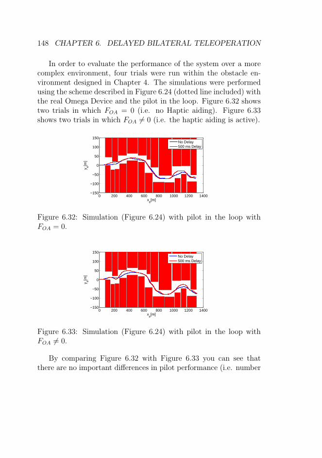
6.32 Simulation (Figure 6.24) with pilot in the loop withFOA = 0. . . . . . . . . . . . . . . . . . . . . . . . . . 148
6.33 Simulation (Figure 6.24) with pilot in the loop withFOA 6= 0. . . . . . . . . . . . . . . . . . . . . . . . . . 148
6.34 Simulation (Figure 6.24) with pilot in the loop withFOA = 0 in fog conditions. The blue line shows the NoDelay trial. The green line shows the 500 ms Delaytrial. . . . . . . . . . . . . . . . . . . . . . . . . . . . 149
6.35 Simulation (Figure 6.24) with pilot in the loop withFOA 6= 0 in fog conditions. The blue line shows the NoDelay trial. The green line shows the 500 ms Delaytrial. . . . . . . . . . . . . . . . . . . . . . . . . . . . 149
C.2 The Hess Structural Model [79]. . . . . . . . . . . . . 179
C.3 Human plus Plant Bode plot. . . . . . . . . . . . . . 180
C.4 The Evans’ Root Locus used to design the compen-sator CLat(s). From the left, the second and the thirdfigures are a zoom around the origin. . . . . . . . . . 181
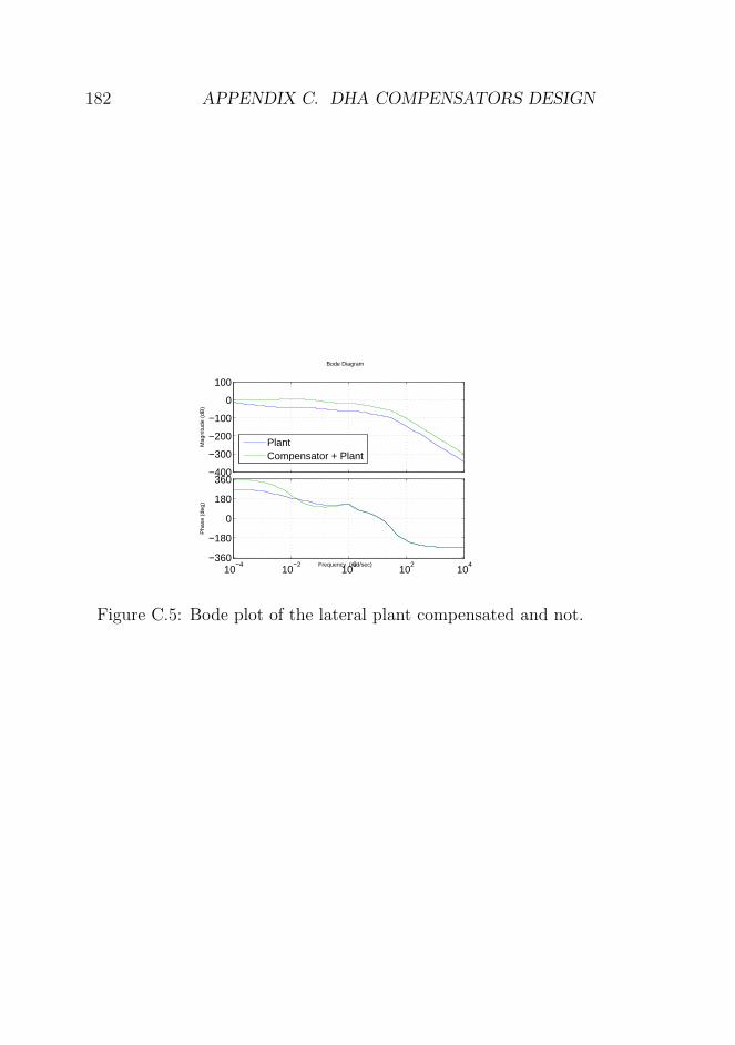
C.5 Bode plot of the lateral plant compensated and not. . 182
D.1 CAAF Experiment detailed results. Find in the verti-cal axes the IAE about the task altitude. The missingbars refer to trials in which the aerodynamic stall hap-pened (non-linear aircraft dynamics and naive partic-ipants, i.e. not professional pilots, were employed inthis experiment). . . . . . . . . . . . . . . . . . . . . 185
D.2 The CAAF VS DHA Experiment detailed results. . . 188
D.3 One of the five employed scenarios. . . . . . . . . . . 189
D.4 The Obstacle Avoidance Experiment detailed results(A=Minimum Fog condition; B=Medium Fog condi-tion; C=Maximum Fog condition). . . . . . . . . . . 191
xviii LIST OF FIGURES
D.5 The MIXED-CAAF/OAF VS DHA Experiment de-tailed results (NW=No Wind condition; W=Windcondition; A=Minimum Fog condition; B=MaximumFog condition). . . . . . . . . . . . . . . . . . . . . . 193
D.1 The blocks order of presentation for each of the 18 par-ticipants (1=NoF; 2=Single VS CAAF Force; 3=Dou-ble VS CAAF Force). . . . . . . . . . . . . . . . . . . 194
D.2 The blocks order of presentation for each of the 7 pro-fessional pilots. 1: NoEF ; 2: IHA; 3: DHA. . . . . . 194
D.3 Example of planned force conditions and scenario typesfor each one of the 10 participant. 1: NoEF ; 2: IHA;3: DHA. . . . . . . . . . . . . . . . . . . . . . . . . . 195
D.4 Example of planned force conditions and scenario typesfor one of the 7 participants. 1: NoEF ; 2: IHA; 3:DHA. . . . . . . . . . . . . . . . . . . . . . . . . . . 195
xix
xx LIST OF TABLES
Chapter 1
Introduction
1.1 Unmanned Aerial Vehicles
Unmanned Aerial Vehicle (UAV) is the name commonly used to de-scribe an airborne vehicle without any pilot on-board, which operatesunder either remote or autonomous control. UAVs are also referredas Remotely Piloted Vehicles (RPVs), Remotely Operated Aircrafts(ROAs), Unmanned Vehicles Systems (UVSs) or simply Drones. Inmost instances, the term RPV might be more appropriate as thename suggests that the vehicle is remotely controlled and still rely,to a great degree, on human involvement.
UAVs are mainly employed in military field. Lessons from recentcombat experiences in Kosovo, Afghanistan and Iraq have shownthat UAVs can provide vastly improved acquisition and more rapiddissemination of Intelligence, Surveillance and Reconnaissance (ISR)data [9]. Over the past several years, a confluence of events anddevelopments has brought the Military Services to change the wayof perceiving the UAVs. These include:
. Dramatic increases in computer processing power;
. Advances in sensor technologies that reduce sensor size and
1
2 CHAPTER 1. INTRODUCTION
weight, provide high resolution, and permit detection of fixedand moving targets under a variety of environmental condi-tions;
. Improved communications, image processing, and image ex-ploitation capabilities.
UAVs have the potential to reduce operational and support costas compared to the use of manned aircraft [8].
Currently UAVs have a permanent position in the military ar-senal in the US, Europe, Middle East and Asia. Today UAV de-velopment strives toward more peaceful and civil usage [10] such asrescue, border surveillance, disaster monitoring, telecommunicationsrelay, fire fighting, traffic monitoring, pipeline surveillance, agricul-ture, construction, and public utility operations [61]. Thus, police,forest rangers, fire brigades are very interested on them for pub-lic security. UAVs civil employment also includes video-taping forphotogrammetric or scientific applications [7].
Communications represent the most important subsystem forUAVs. Bandwidth is needed to support systems that control theUAVs flight, launch and recovery, to transmit the output of on boardsensors to both line of sight and beyond line of sight processing cen-ters, and to communicate with air traffic control centers. Equallyimportant is the recognition of a mission area for UAVs acting ascommunication relays linking tactical forces, including other UAVs,and providing connection to support centers.
The potential benefits of UAVs, such as low operational cost andno risk of losing human lives, make sense when the teleoperation issafe and no mishaps and accidents occur. A crash of a UAV duringteleoperation will not only lead to possible damage to the local en-vironment, but could also lead to the loss of the vehicle. Humansin the vicinity of the incident may get injured as well. Therefore,safety in UAV teleoperation is of great importance not only for mis-sion success but also to preserve the sustainability of UAV operations
1.2. MANUAL VS AUTONOMOUS CONTROL 3
[12].
1.2 Manual vs autonomous control
Various ways to control UAVs exist. They can be categorized inautonomous control and manual control.
Some of the problems associated with the automatic control are[10]:
. Reduced situation awareness;
. Increased monitoring demands;
. Cognitive overload;
. Mis-calibration of trust in automation (either excessive trust,termed ”complacency”, or, at the other extreme, mistrust ofautomation);
. Inability to reassume manual control;
. Degraded manual skills through lack of practice;
. The need for new selection and training procedures;
. Increase in the risk of human error because of the human weak-ness to maintain vigilance during extended periods of relativelylow task demand.
4 CHAPTER 1. INTRODUCTION
Furthermore, fully-autonomous systems are more suitable forsimple missions with, for example, pre-defined targets and far awayfrom inhabited environments. Manual teleoperation could enablemore flexibility in controlling a UAV close to inhabited environmentsand without predefined targets [12]. This is suitable for civil appli-cations such as reconnaissance, surveillance tasks and it is subjectedto failures. Focusing on manual control would give to the pilot thefreedom to choose the targets step by step (for example because oflast minute communication from control towers). Furthermore, thecomplex scenarios in which UAVs would operate requires the pres-ence of the human operator in the decision making system.
For all these reasons, keeping a human operator in-the-loop isrequired.
1.3 UAV Mishaps
There are several factors at work contributing to UAV mishaps.Besides electro-mechanical failures (62%), mishaps and incidents
in UAV teleoperation are, for a great part, due to human errorsduring operation (25%) [8]. This is essentially due to the lack of thenatural, multiple-sensory information of the environment. In fact,the remote pilot is inside the Control Ground Station (CGS)(seeFigure 1.1) which is characterized by the following troubles:
. Limited Field Of View cameras (i.e. no ”look around” possi-bility, etc.);
. No inertial cues (motion, vibrations, gravity/attitude etc.);
. No auditory cues;
. Video/data communication delays;
. No feedback on control stick of the environment around theremote vehicle (obstacles, disturbances etc.).
1.3. UAV MISHAPS 5
Figure 1.1: UAV remote piloting from a Control Ground Station(picture from http://www.flickr.com).
Usually, in order to solve the first mentioned trouble, the UAVoperator is supplied with a richer visual information like showing dif-ferent cameras on various displays. Another alternative is to supplythe operator with a continuously updated ”augmented reality” or”synthetic vision” produced by a computer resembling reality [21].As concerning the inertial cues, some steps on the employment ofmotion cueing to augment UAV operator performance and improveUAV flight training was made [22, 23]. About the auditory cues,augmented reality through multi modal tactile and auditory infor-mation displays has been used in other fields to resemble reality[10, 24]. The communication delays, depending on the situation,turn out in the range of 100 to 1600 ms (and even more). Thisis a considerable amount given that 100 ms delay usually leads tomeasurable degradation of human performance [29, 27]. Delays ofabout 250-300 ms quite often lead to unacceptable airplane handlingqualities [33]. Other techniques were used in the past to improve theperformance of a teleoperator in presence of time delay; for instance,automatic switching for stopping override [26] or the use of the pre-
6 CHAPTER 1. INTRODUCTION
dicted display [25]. As concerning the haptic feedback, tactile cueshave shown to complement the visual information (through the vi-sual displays of a remote CGS) and improve the efficiency of theUAV teleoperation [21, 1, 10].
In conclusion, augmented feedback to the operator such as hapticfeedback and multi modal displays can compensate, to some extent,for the lack of sensory cues that would be presented to UAV operators[10]. Introducing the mentioned augmented feedbacks in the CGSwould hopefully imply a reduction of the UAV mishaps.
Thus, investing in a human machine interface design tailored onthe human needs would improve the operator situational awarenessand maybe the performances.
1.4 Situational Awareness
By the late 1980s, there was a growing interest in understandinghow pilots maintain awareness about the many complex and dy-namic events that can occur simultaneously in flight, and how thisinformation was employed to guide future actions. The vast quanti-ties of sensor information available in the modern cockpit, coupledwith the flight crew’s ”new” role as a monitor of aircraft automa-tion, increased interest on Situational Awareness (SA) issue [13].Through the word ”situation(al) awareness”, the processes of atten-tion, perception, and decision making that together form a pilot’smental model of the current situation of the aircraft is described [15].According to [18], the crews knowledge of both the internal and ex-ternal states of the aircraft, as well as the environment in which itis operating is defined as SA.
In fact, the internal state of the aircraft that is the ’health’ of itsutility systems and terrain, threats, and weather that correspondsto the external environment must be monitored.
To expand upon this definition, Endsley [16], described the threehierarchical phases of SA: perception, comprehension, and projec-
1.4. SITUATIONAL AWARENESS 7
tion. The First SA Level, named Perception of the elements in theenvironment, include perceiving the status, attributes, and dynamicsof relevant elements in the environment (airspeed, position, altitude,route, direction of flight etc) and also weather, air traffic controlclearances, emergency information etc. [16]. The Second SA Level,named Comprehension, is based on an understanding of the signifi-cance of the First SA Level elements. The Third SA Level, namedProjection, is based on the knowledge of the status and dynamics ofthe elements and a comprehension of the situation (both First andSeconds SA Levels).
SA is not synonymous with good performance. In fact, havinggood SA might bring good performance: a pilot could have a goodSA without being a good pilot for the lack of motor skills, becauseof co-ordination or attitude problems etc. Conversely, under auto-matic flight conditions it is possible to have good performance withminimal SA [17].
As concerning SA in automation, SA is something that a personcreates himself through perception (First SA Level) and it couldnot be provided by automation which usually exclude the humanoperator from the control loop. Though automation can be thoughtin a different way say supporting SA through decision aids and systeminterfaces. And SA can be hindered if designers fail in adequatelyaddressing the SA needs of the operator [17].
Since SA is created through the perception of the situation (Level1), the quality of SA is very dependent on how the person directsattention and how attention to information is prioritized based on itsperceived importance. Jones and Endsley (1996) found that opera-tors were prone to overlooking crucial information in sustaining SA,though all relevant and needed information was present. Actually,this was found to be the most frequent causal factor associated withSA errors [10].
The above definitions are written in case of aviation in generalbut can be extended to the case of UAV teleoperation as long as the
8 CHAPTER 1. INTRODUCTION
CGS is, in this case, fixed to the ground. Thus, as seen in subsection1.3, being aware of the aircraft internal and external state is muchmore difficult for the pilot. According to [10] haptic feedback cancompensate to some extent for the lack of sensory cues that will bepresented to UAV operators (see subsection 1.3), this means thata way to improve the situational awareness of a remote UAV pilotand the efficiency of the teleoperation is the addiction of a hapticinterface to the visual interface.
1.5 Bilateral Teleoperation
One of the advantages of a teleoperation system is to combine thehuman capabilities with the robot ones. UAVs have also been re-ferred to as non-anthropomorphic robots [41]. Through the teleop-erated systems barriers like distance, hazardness or scaling can beovercome.
Remote teleoperation can be classified into unilateral and bilat-eral. In unilateral teleoperation no haptic feedback is available tothe operator. In bilateral teleoperation, haptic feedback allows theoperator to have a better feeling about the remote environment, pro-viding a more extensive sense of telepresence [39].
The word telepresence refers to an experience that appears toinvolve displacement of the user’s self-perception into a computer-mediated environment [40]. In particular the word telepresence isemployed when the remote environment is real and not synthetic.In this case it is referred as virtual presence [40].
In teleoperation, a human operator conducts a task in a remoteenvironment via master and slave manipulators [29]. In particular, ina haptic teleoperation system, a human operator controls a remotelylocated teleoperator or slave device via a human system interfaceor master device while receiving haptic feedback of the interactionbetween the teleoperator and the (virtual or real) environment.
1.6. GOAL OF THE THESIS 9
Stimulating a human’s sense of touch by managing with sensationof movement or force in muscles, tendons, and joints is referred toas having a kinesthetic or haptic sensory experience [34].
As haptic data from the master site enters the control on slave siteand vice versa, a control loop between the subsystems human-masterand slave-environment is closed over the communication channel.This poses several challenges for control design, above all in thepresence of time delay in the communication links (see section 2.4).
1.6 Goal of the Thesis
The aim of this work is the investigation of possible haptic aidsfor teleoperated systems. In particular this thesis focuses on theteleoperation of UAVs. The principal issue of remote piloting anUAV is represented by the physical separation between pilot andvehicle which causes an almost complete absence of the sensorialinformation usually available when on board.
The purpose of this report is threefold. First, it presents a novelclassification of the haptic aids present in literature in two classes In-direct Haptic Aids (IHA) and Direct Haptic Aids (DHA) (see Chap-ter 2). This is a contribution on the research on the enhancing ofthe UAV pilot Situational Awareness. In fact, by assuming thathaptic aids provide an improvement of the SA, this thesis launches ahighly important challenge that is to explore which haptic feedbackphilosophy should be followed in order to better improve the SA. Inparticular, the main goal of this thesis is to show that the IndirectHaptic Aid philosophy is a valid alternative to the other commonlyused, and published in the scientific literature, approaches whichmainly fall in the Direct Haptic Aid category. Second, it investi-gates the potential of using a novel concept of tactile interactionas an information source of the external conditions of the air boneaircraft. Third, it explores the benefits of multi-modal informationsources on the flight deck, in terms of improving attention and en-
10 CHAPTER 1. INTRODUCTION
hancing flight performance. This work focuses on the investigationof possible haptic cues meant to improve the virtual immersion ofthe remote pilot. Three novel haptic feedbacks were designed. Thefirst one is a reality-inspired haptic aid since it was built to trans-mit to the UAV teleoperator a realistic situation which is happeningoutside the aircraft: the external disturbances such as wind gusts.The second one is an artificial component since it depends on envi-ronmental constraints. The third one is both a reality and a virtualreality-inspired haptic aid and it merges the first two haptic feed-backs.
The haptic feedbacks will be provided to the human operatorvia a haptic control device. As concerning the reality-based hapticfeedback, the research resulted in the Conventional Aircraft ArtificialFeel. As concerning the artificial-based haptic feedback, the researchresulted in a novel philosophy of an obstacle avoidance haptic feed-back, the Obstacle Avoidance Feel, which was built to help the UAVteleoperator in detecting and hopefully avoiding the obstacles. Asconcerning the mixed reality/virtual reality-based haptic feedback,the research resulted in the Mixed Conventional Aircraft ArtificialFeel/Obstacle Avoidance Feel which extends the previously describedhaptic aid systems by merging them into a system capable of aidinga pilot involved in a flight within a constrain environment in thepresence of wind gusts.
The above just introduced haptic feedbacks both fall in the classof Indirect Haptic Aids. The mentioned Conventional Aircraft Ar-tificial Feel will be shown to increase the performance in terms ofinstinctive response to a stimulus in pilots without any previoustraining on the experiment. It also improves the situational aware-ness intended as making the pilot to feel as piloting the aircraft onboard. The Obstacle Avoidance Feel will be shown to provide anet improvement in the operator sensation with respect to the ex-isting obstacle avoidance haptic aids from the Direct Haptic Aidsclass. This would improve the safety of the teleoperation by keep-
1.7. THESIS OUTLINE 11
ing higher the attention of the pilot in the task and improve thesituational awareness.
1.7 Thesis outline
The structure of this report is the following: Chapter 2 presents areview about the haptic aids published in literature and classifiesthem in two classes: Direct Haptic Aid (DHA) and Indirect HapticAid (IHA). It also shows the problem of the presence of delay inthe communication link of a bilateral teleoperation and it mentionsthe remedies proposed in literature. Chapter 3 describes in detailsthe Conventional Aircraft Artificial Feel (CAAF) which, as will beshown, belongs to the IHA class. The newly introduced CAAF hap-tic force was evaluated and Section 3.6 shows the evaluation results.Chapter 4 describes in details the Obstacle Avoidance Feel (OAF)which, as will be shown, also belongs to the IHA class. The newlyintroduced OAF haptic force was evaluated and Section 4.5 showsthe evaluation results. Chapter 5 presents and evaluates (see Sec-tion 5.6) the Mixed Conventional Aircraft Artificial Feel/ObstacleAvoidance Feel (Mixed-CAAF/OAF), belonging to the IHA-class aswell. It was evaluated as well and Section 5.6 shows the experimen-tal results. Finally, the Chapter 6 considers the introduction of thetime delay in the communication link and proposes the applicationof an admittance-control scheme for the master side with the newintroduction of an observer to estimate the human operator force incase of lack of force sensors in the employed haptic device.
12 CHAPTER 1. INTRODUCTION
Chapter 2
Haptic Systems
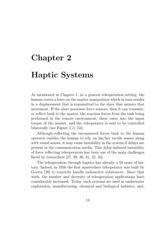
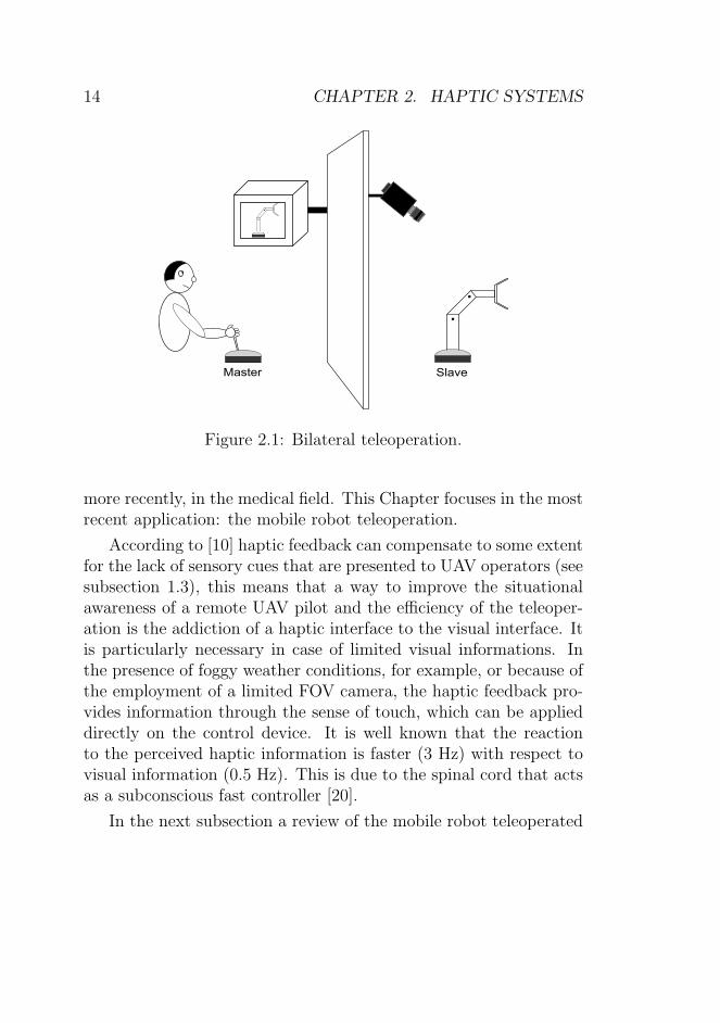
As mentioned in Chapter 1, in a general teleoperation setting, thehuman exerts a force on the master manipulator which in turn resultsin a displacement that is transmitted to the slave that mimics thatmovement. If the slave possesses force sensors, then it can transmit,or reflect back to the master, the reaction forces from the task beingperformed in the remote environment; these enter into the inputtorque of the master, and the teleoperator is said to be controlledbilaterally (see Figure 2.1) [54].
Although reflecting the encountered forces back to the humanoperator enables the human to rely on his/her tactile senses alongwith visual senses, it may cause instability in the system if delays arepresent in the communication media. This delay-induced instabilityof force reflecting teleoperators has been one of the main challengesfaced by researchers [27, 29, 30, 31, 32, 33].
The teleoperation through haptics has already a 50 years of his-tory. Indeed, in 1950 the first masterslave teleoperator was built byGoertz [38] to remotely handle radioactive substances. Since thatwork, the number and diversity of teleoperation applications haveconsiderably increased. Today, such systems are used in underwaterexploration, manufacturing, chemical and biological industry, and,
13
14 CHAPTER 2. HAPTIC SYSTEMS
Master
.
.
.
.
Slave
Figure 2.1: Bilateral teleoperation.
more recently, in the medical field. This Chapter focuses in the mostrecent application: the mobile robot teleoperation.
According to [10] haptic feedback can compensate to some extentfor the lack of sensory cues that are presented to UAV operators (seesubsection 1.3), this means that a way to improve the situationalawareness of a remote UAV pilot and the efficiency of the teleoper-ation is the addiction of a haptic interface to the visual interface. Itis particularly necessary in case of limited visual informations. Inthe presence of foggy weather conditions, for example, or because ofthe employment of a limited FOV camera, the haptic feedback pro-vides information through the sense of touch, which can be applieddirectly on the control device. It is well known that the reactionto the perceived haptic information is faster (3 Hz) with respect tovisual information (0.5 Hz). This is due to the spinal cord that actsas a subconscious fast controller [20].
In the next subsection a review of the mobile robot teleoperated
2.1. ROBOT BILATERAL (TELE)OPERATION REVIEW 15
systems is presented.
2.1 Robot Bilateral (Tele)operation Re-
view
Some of the numerous applications of teleoperation are operatingspace robots from ground, commanding unmanned underwater vehi-cles, handling hazardous materials, maneuvering mobile robots withobstacle avoidance. The present section focuses on the teleoperationof mobile robots.
The following subsections review the Ground Mobile Robots andManned and Unmanned Aerial Vehicles bilateral teleoperations.
2.1.1 Ground Mobile Robots
This subsection presents a review about the teleoperation of groundmobile robots. Reference [4] makes use of a haptic interface in or-der to increase the users perception of the workspace of the mobilerobot. In particular, a virtual interaction force is computed on thebasis of obstacles surrounding the mobile vehicle in order to preventdangerous contacts, so that navigation tasks can be carried out withgenerally better performances. When an obstacle is close enoughto the mobile robot it exerts a spring damper virtual force on theteleoperator through the haptic device in order to help him/her inavoiding the collision with the obstacle.
Also in [55] the force feedback is based on measured distancesfrom the mobile robot to the obstacles. The force feedback gain isvariable based on measured distances to the obstacle and derivativesof the distances. Clearly, the gain is higher when the obstacle andthe mobile robot approach each other than when obstacle and robotare moving away from each other.
16 CHAPTER 2. HAPTIC SYSTEMS
In [56] the goal location exerts an attractive force on the teleoper-ator which is proportional to the distance between the goal locationand the mobile robot.
References [4, 55, 46] make use of the Car-Driving Metaphorwhich utilizes position-velocity kinematic mapping: the displace-ment of the end-effector of the haptic device is mapped to the linearand angular velocities of the mobile robot. A 3D approach of thecar-driving metaphor is presented in [57]: the Intuitive Haptic Con-ical Control Surface. Here, the third vertical coordinate providesthe current velocity of the robot and so the conical surface allowsintuitive haptic detection of the zero speed. For example, a force di-rected to the zero speed point (the cone’s vertex) is a suggestion tothe teleoperator to decrease the commanded velocity of the mobilerobot.
Also in [46] the obstacle force feedback exerted on the teleopera-tor is a repulsive one and it is proportional to the distance betweenthe robot and the obstacles.
2.1.2 Manned and Unmanned Aerial Vehicles
The present section presents a literature review concerning operation(remote or not) of aerial vehicles, both manned and unmanned. In[59], 68 actuators form a vibrotactile image that can be updated inreal-time navigation, hovering, threat warning, spatial disorientationcountermeasures, communication, etc. The actuators are attachedto the body and communicate information by vibrating at a spe-cific location. The most simple set-up is when only one actuatorvibrates: it is attached to that side of the body that correspondsto the desired direction of movement. Possible applications in land(navigation support and threat warnings for drivers, infantrymen,blind people, etc.), underwater (divers), and in space (astronauts inthe International Space Station).
Reference [1] investigated the application of haptic feedback in
2.1. ROBOT BILATERAL (TELE)OPERATION REVIEW 17
UAV teleoperation for collision avoidance in low airspace by map-ping of the environmental constraints that can even be outside thevisual FOV. In the context of teleoperated systems where visual cuesonly have usually been used, the adoption of an artificial feel systemfor the stick appears to increase the situational awareness; this isextremely relevant for UAVs.
Tactile cues have shown to complement the visual information(through the visual displays of a remote CGS) and improve the ef-ficiency of the teleoperation [1]. The task of the experiment wasto fly from waypoint to waypoint as accurately as possible in anobstacle-laden environment. Stick deflection tilt the Swashplate (asin a real helicopter). The force on stick was proportional to thedistance between the UAV and the obstacles.
They showed with a rather complex remote piloting and obsta-cle avoidance simulations that an appropriate haptic augmentationmay provide the pilot a beneficial effect in terms of performance inits task. The authors extensively studied the problem of force feed-back (injecting an artificial force on the stick) and stiffness feedback(changing stick stiffness to oppose less or more strongly to motion).The active deflection of the stick given from the force feedback canbe considered an ”autonomous collision avoidance” function. In fact,the force feedback can be regarded to yield a ”commanded” stick de-flection that the operator should follow as much as possible. Thatis, when yielding to the forces applied on the hand, the operatordeflects the stick in a way that satisfies the collision avoidance func-tion. With stiffness feedback instead, the stick becomes stiffer whenin the presence of an obstacle, that is, the extra stiffness providesan impedance, resulting in an extra force that depends on the de-flection of the stick by the operator. The authors then concludedthat a mixed force-stiffness feedback is the best solution. This typeof haptic augmentation systems for RPVs was designed in order tohelp directly the pilot in his/her task by pulling the stick in the cor-rect direction for the achievement of the task, or by changing stick
18 CHAPTER 2. HAPTIC SYSTEMS
stiffness in order to facilitate or oppose to certain pilot’s actions[78, 1].
Another work not about teleoperation but still about haptic aug-mentation is the one by De Stigter [58]: he suggests to use the hapticdevice similarly to the artificial horizon with flight director (as in theInstrumental Landing System, ILS, for instance): as bringing the ar-tificial horizon bar in the center would let the aircraft to fly in thedesired direction, by bringing the haptic device to the central posi-tion the target path will be followed in a close future. In fact, thehaptic device moves in the opposite direction with respect to theone required by the target path and about a quantity proportionalto the future error with respect the path to follow.
Reference [60] proposes the introduction of an active stick in amanned military aircraft (Alenia Aermacchi M-346). In trainingaircrafts, the introduction of an active stick in each cockpit wouldbe very useful as long as the two sticks can be electrically connected;thus they could work in a synchronous way as they were mechanicallyconnected. In this way, the trainer gets the chance to supervise thecontrol input of the apprentice pilot. The trainer could also makelittle corrections to teach the best way to impart some maneuver tothe aircraft. The active stick would move also coherently with theautopilot commands to inform the pilot about the approaching of theenvelope limits (already present in fly-by-wire aircrafts through thestick shaker). This is in line with what is stated in [19]: the activestick in this case makes the system structure and the automationprocesses visible to the operator. This aid in identifying options foraction can help the operator in maintaining SA.
2.2. HAPTIC AIDS ANALYSIS AND CLASSIFICATION 19
2.2 Haptic aids analysis and classifica-
tion
Most of the described papers focus on a collision avoidance supportto help the pilot in avoiding obstacles. Usually this kind of hapticaids, for example, have always been represented by repulsive forcescreated by objects in the environment in order to help the operatorto avoid them.
When the task is instead a path to follow, a target location toreach or a desired stick position to get, the haptic feedback is insteadattractive with respect to the task.
Thus, in all the described papers except for the [58], the hapticforce that is artificially injected in the stick has the same sign (i.e.direction) as the one needed in order to achieve the requested task;thus the operator has to be compliant with it in order to avoid theobstacles or to reach the desired position.
As concerning the work [58] instead, the haptic force has theopposite sign with respect to the one desired in order to achievethe requested task and the human operator has to appose the forceexerted from the stick by keeping the stick in the center while thehaptic force tries to move it away on the sides.
Due to the last considerations, the haptic force used in the bi-lateral teleoperation of RPV can be divided in two philosophies:Indirect Haptic Aiding (IHA) versus Direct Haptic Aiding (DHA).
Direct Haptic Aid: the class of all Haptic aids which produceforces and/or sensations (due to stick stiffness changes for instance)aimed at ”forcing” or ”facilitating” the pilot to take some actionsinstead of others. The operator has to be compliant with the forcefelt on the stick to achieve the task.
Indirect Haptic Aid: the class of haptic aids where the sense oftouch is used to provide the pilot with an additional source of infor-mation that would help him/her, indirectly, by letting him/her knowwhat is happening in the remote environment and leaving him/her
20 CHAPTER 2. HAPTIC SYSTEMS
the full authority to take control decisions. In general, in this casethe operator has to oppose to the force felt on the haptic device.
It is clear from the above definitions that these two classes ofhaptic aids are complementary.
In practice under DHA, the haptic feedback suggests the correctdirection the pilot should move the stick in order to achieve thetask and the operator has to be compliant with it, while under IHAthe haptic feedback is, in general, in the opposite direction and theoperator has, in general, to oppose to it.
The stretch reflex, which is a reflex contraction of a muscle inresponse to passive longitudinal stretching, is an highly automaticmotor response that is believed to be the spinal reflex with the short-est latency [77]. The author believe that the stretch reflex is involvedwhen using IHA-based haptic feedback. Thus, a strength point ofIHA is that, as a matter of fact, when a haptic input requires a reac-tion to a stimuli rather than compliance, it might be more ”natural”for the human being [77, 3].
Another difference between the two classes is the behavior of thesystem with the pilot out of the loop: the DHA approach closes theloop itself as long as it is an ”almost-automatic-system-concept”.The IHA approach instead, as will be clarified later, is more likelyto produce a system that requires the presence of an operator in theloop in order to achieve the task. As a matter of fact, with DHA in anobstacle avoidance task the obstacle itself exerts a force on the stickwhich in turn makes the robot to change the movement directioneven if the pilot is out of the loop. While, in the path following taskof [58] (which according to the previous definitions would fall in theIHA class) when the stick moves on one side because of a future errorin the path following, the error is doomed to rise if an external force(say the pilot) does not bring the stick in the center.
2.3. REALITY-BASED HAPTIC AIDS 21
2.3 Reality-Based Haptic Aids
All the papers described so far are based on a haptic aid which doesnot exist in reality. In fact, they all artificially produce a hapticforce linked to environmental constraints or to environmental goals(a specific target location, a path to follow or a desired maneuver).
One study [34] explored, instead, how to provide the UAV pilotwith an enhanced indication about a real condition existing outsidethe aircraft. In fact, the authors examined the value of haptic dis-plays for alerting UAV operators to the onset of turbulence whichwas identified as being potentially detrimental to safe and effectiveUAV control by the UAV operators themselves. This is especiallytrue for UAVs that require direct manual control in order to land.
The data in [34] revealed that haptic alerts, conveyed via theUAV operators joystick, could indeed improve self-rated situationawareness during turbulent conditions in a simulated UAV approachand landing task. These improvements might result either from anincrease in the operator’s ”presence” in the remote environment [62],from increased information by effective use of multi-sensory stimu-lation [63], or a combination of the two.
Before [34], turbulence was indicated solely by an unexpectedperturbation of video images being transmitted from a UAV-mountedcamera to the operator control station, appearing in the Head-UpDisplay (HUD).
Due to limitations inherent with reducing all environmental in-formation to the visual channel, UAV operators may fail to perceive,or fail to correctly diagnose this video perturbation as sudden turbu-lences. In [34] visual feedback was supplemented by haptic feedbackapplied directly to the pilots control stick, providing a redundant,kinesthetic alert: a force reflection in the axis-direction and scaled-ratio magnitude of the turbulence event.
In the same paper, four different alerts were evaluated and com-pared: Visual (perturbation of nose-camera imagery in the HUD
22 CHAPTER 2. HAPTIC SYSTEMS
Baseline), Visual/Haptic (Visual and additional 1 second, low gain,high frequency vibration of the control stick), Visual/Aural (Visualand 1 second pure tone), Visual/Aural/Haptic (all three cues si-multaneously). Data were collected from pilots as they performedsimulated landing tasks. Conditions containing the haptic cue (Vi-sual/Haptic and Visual/ Haptic/Aural) resulted in less error thannon-haptic cue conditions (Visual and Visual/Aural). Although theaural alert also improved landing accuracy and detection of turbu-lence direction, performance was best with the redundant kinestheticfeedback. When randomly interrogated regarding the primary direc-tion of the UAV immediately following a turbulence event, partici-pants were more accurate when haptic feedback was present [34].
Interestingly, these results were true despite the fact that thehaptic signals were not designed to closely simulate or mimic theveridical haptic information experienced by the pilot of a mannedvehicle [10]. In fact, as said, the turbulence was transmitted througha low gain, high frequency vibration of the control stick.
2.4 Time Delays
As mentioned, a teleoperation system in presence of force feedbackis referred as bilateral system. In such systems, the human opera-tor controls a remotely located teleoperator. The UAV operator isresponsible for the UAV at all times, it is crucial that he/she at alltimes can understand the UAV. Informational transfers through thedatalink have to be without delays that can have an effect on systemperformance and overall safety. It is vital that control inputs andorders can be executed immediately in emergency situations thatrequire such actions. Datalink delays could be of various magni-tude (from 100 to 1600 ms or more) and not always predictable tohuman operators, and can thus cause a lack of understanding withincreased cognitive workload, decreased situational awareness andpossible incorrect inputs as result with final failure of the mission
2.4. TIME DELAYS 23
[10].Different ways to improve the performance of a teleoperated sys-
tem in presence of time delay exist in literature, starting from themove and wait strategy [28], that is initiating a control move andthen waiting to see the response of the remote robot until the taskis accomplished, to the more advanced control theory. The firstmethods regard automatic switching for stopping override [26], su-pervisory control [64] or the use of the predictive display [25, 65]. Be-ginning in the mid 1980s, more advanced control theoretic methodsstarted to appear, such as Lyapunov-based analysis [66] and internalvirtual model [67]. In the late 1980s and 1990s, network theory startsto grow up through impedance representation [68] and passivity the-ory with [29, 30, 31] and without [32] the scattering variables (wavevariables transformation). Reference [37, 36] through the two/fourchannel architectures and the impedance/hybrid matrix approachstarted mentioning the trade off between stability and transparency.In the 1990s the teleoperation through Internet started and the prob-lem of packets loss grew up [69]. Other methods overcome the in-stability problems bilateral teleoperation in presence of time delayare the admittance control [43, 14], the adaptive control [35] andthe time domain passivity [36, 71]. Another way to handle the timedelay communication and the loss of packets is the sampled Port-Hemiltonian approach [72]. In particular, while the passivity methodpresents a trade off between the stability and the transparency, thePort-Hemiltonian approach allows both stable and transparent be-havior [72].
24 CHAPTER 2. HAPTIC SYSTEMS
Chapter 3
Conventional AircraftArtificial Feel
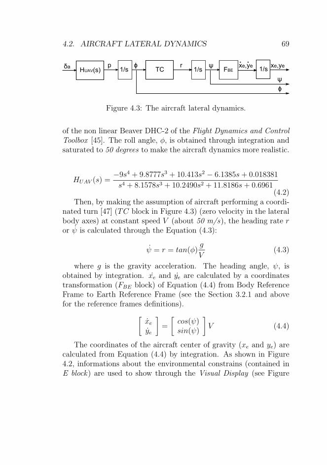
A typical trouble of remote piloting an RPV is the lack of situa-tion awareness because of the physical separation between the pilot(inside the Control Ground Station, CGS) and the airborne RPV.Visual feedback only is usually provided by UAVs Ground ControlStations; when an external disturbance or a fault, which on a con-ventional aircraft would produce a perceptible effect on the stick,affects the RPV, the pilot has to understand this situation by look-ing at the output of the instruments only. When a vertical windgust disturbance affects a manned aircraft, the change in angle ofattack and wing load are practically instantaneous. This has alsoan immediate effect on a mechanical-linkage based control column.The altimeter on the GCS cockpit will show the resulting change inaltitude with a certain delay with respect to the actual disturbancetime; as a matter of fact the aircraft dynamics has a low pass behav-ior and phase lag from angle of attack to altitude (in the simplestlinear approximation it behaves as an integrator).
As said in Section 1.4, automation usually does not provide orcould hinder SA if the designers fail in adequately addressing the
SA needs of the operator. But automation can also, in many dif-ferent ways, be created to support good SA through decision aidsand system interfaces. IHA-CAAF was introduced to satisfy such adifferent way to create SA.
Operators where prone in overlooking crucial information to sus-tain SA, though all relevant and needed informations were present.This was found to be the most frequent causal factor associated withSA errors [10]. Through the IHA-CAAF they do not have to thinkabout their response at the haptic aid because IHA-CAAF is builtin a way that their response will be natural and instinctive.
Furthermore, by considering that UAVs pilots are also mannedaircrafts pilots, they expect, in presence of external disturbancessuch as wind gusts or turbulences, a stick cueing which is similar tothe one they would feel by piloting the aircraft on board. Thus, agood way to inform the remote pilot about the external disturbancescould be perhaps to reproduce, through the haptic feedback, a feelingwhich mimics the real one.
The IHA-CAAF haptic feedback will be shown to increase theperformance in terms of instinctive response to a stimulus in pilotswithout any previous training on the experiment. It also improvesthe situational awareness intended as making the pilot to feel aspiloting the aircraft on board. This would improve the safety of theteleoperation by keeping higher the attention of the pilot in the task.
3.1 FBW Aircrafts/UAVs Analogy
As said this work is based on UAV feedback augmentation butnonetheless similar techniques could be employed in similar fieldslike Fly-By-Wire (FBW) piloted commercial aircrafts or helicopters.
A FBW system is an electrically-signaled aircraft control system,a computer-configured controller, that modifies the manual inputs ofthe pilot in accordance with control parameters. The movements ofthe flight control, the sidestick, are converted to electronic signals,
3.1. FBW AIRCRAFTS/UAVS ANALOGY 27
and flight control computers determine how to move the actuatorsat each control surface to provide the expected response.
FBW aircrafts (Airbus, Boeing 777 and later designs) present,at least as concerning the haptic feedback, similar loss of situationalawareness compared to the previous technology, i.e. the mechani-cally driven aircrafts (see later the Section 3.2).
In fact, FBW system employed both in large airliners and inmilitary jet aircraft, dispenses all the complexity of the mechanicalcircuit of the mechanical flight control system and replaces it withan electrical circuit. The FBW (also referred as irreversible controlsystem [47]) makes use of an electronic passive sidestick, in placeof the conventional control stick which was connected to the actualaerodynamic surfaces via mechanical linkages (reversible control sys-tem [47]). The sidestick is in general implemented as a spring systemwith constant stiffness that makes the force felt by the pilot strongeras the displacement of the stick increases independently from theparticular aerodynamic situation (velocity, load factor). Sometimesthe sidestick may provide an artificial vibration of the stick (stickshaker) and some acoustical/visual warning that makes the pilot toknow that the limits of the flight envelope (see Section A.2 for de-tails) are going to be reached [74].
The employment of fully powered controls made essential theintroduction of completely artificial feel [75]. In that time, a con-siderable speculation about what elements of natural feel should beemulated, started. It was also coupled with the natural desire tominimize the cost and complexity of the feel devices.
The possibilities included control force variation with dynamicpressure (q feel), speed (V feel) or control deflection only (springfeel). Devices such as bobweights and downsprings which were al-ready familiar on conventional aircraft, were sometime included aswell. Mechanical controls also carry out the role of a tactile display:the human hand can interpret loading forces appearing on the hand-grip in terms of demands imposed on the system and its expectable
response, enabling the pilot to develop a beneficial phase lead [76].Artificial feel had become more and more fundamental in addic-
tion to the visual cueing in the context of RPVs.
3.2 Mechanically Driven Aircrafts
As said, a meaningful way to inform the remote pilot about the ex-ternal disturbances is the reproduction, through the haptic feedback,of a feeling which mimics the one transmitted to the pilot on boardof a manned mechanically driven aircraft. In this case, the pilot feelsall the aerodynamic forces (external disturbances as wind gusts andturbulences) directly on the bar, the control device. The force felt bya pilot on the aircraft control device of a mechanical Flight ControlSystem (FCS) during a maneuver depends in a very complex mannerfrom all the aerodynamics characteristics of the aircraft, the currentstate of the aircraft (speed, angle of attack etc.) and of course fromcontrol device deflection. By taking into consideration the only lon-gitudinal dynamics (pitch and altitude motion), the force felt by thepilot of a mechanically driven aircraft is [47]:
where ηh is the dynamic pressure ratio at horizontal tail, Ch isthe elevator hinge moment, q is the dynamic pressure of the aircraftwhich is defined as
q =1
2ρV 2
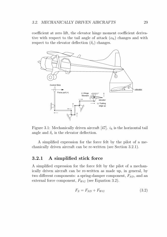
(where ρ is the air density and V is the airspeed), Se and ce arethe surface and the chord of the elevator and Ge is a gearing factor(with units) to convert moments to force and includes the geometryof the control mechanisms, pulleys, push-rods and cables (see Figure3.1). Ch0, Ch,α and Ch,δ are respectively the elevator hinge moment
3.2. MECHANICALLY DRIVEN AIRCRAFTS 29
coefficient at zero lift, the elevator hinge moment coefficient deriva-tive with respect to the tail angle of attack (αh) changes and withrespect to the elevator deflection (δe) changes.
.ih
δe
.
. .
. .
...
.
.
Control Stick
Force pull (+)
elevator
(-) Hinge
Moment
(-) Trailing
edge up
elevator
Figure 3.1: Mechanically driven aircraft [47]. ih is the horizontal tailangle and δe is the elevator deflection.
A simplified expression for the force felt by the pilot of a me-chanically driven aircraft can be re-written (see Section 3.2.1).
3.2.1 A simplified stick force
A simplified expression for the force felt by the pilot of a mechan-ically driven aircraft can be re-written as made up, in general, bytwo different components: a spring-damper component, FSD, and anexternal force component, FWG (see Equation 3.2).
∆δe is the change in the commanded elevator deflection with re-spect to the trim condition deflection. α is the aircraft angle ofattack, which is the angle between the direction of motion (relativevelocity) and the x-axes of the Body Reference Frame (left-handedframe with origin in the center of gravity of the aircraft, xB is in thevertical plane of symmetry of the aircraft and points the nose of it,yB axes is in the plane perpendicular to the plane of vertical symme-try and points to the right side), αtrim is the angle of attack in trimcondition (see later), ǫ is the downwash angle produced on the hori-zontal tail by the wings airflow. A justification for the approximateexpression of Equation (3.3) is given in the Section 3.2.2.
3.2.2 Simplified Stick Force Proof
The longitudinal steady state equations in horizontal flight in WindAxes (left-handed coordinate system with xW same direction as therelative velocity and zW downward, origin in the aircraft center ofgravity) are written as [47]:
{
W = L = CL · qS
0 = m = Cm · cqS(3.4)
where W , L and m are respectively the aircraft total weight,lift and pitching moment; CL and Cm are respectively the aircraftlift and pitching moment coefficients. c is the mean wing chord.The Equation (3.4) can be re-written by expressing the lift and themoment coefficients as in the Equation (3.5):
In Equation (3.5), CL0 and Cm0 are respectively lift and pitchmoment coefficients for zero angle of attack α. CLα, CL,ih, CLδ rep-resent the change in lift coefficient with respectively the angle ofattack (the aircraft lift curve slope), α, the horizontal tail incidenceangle, ih, and the elevator deflection, δe (see Figure 3.1). Cmα, Cm,ih
and Cmδ are equivalent variations of the pitching moment coefficient.As usual, q and S are dynamic pressure and the wings area. Thesolutions of Equation (3.5) are referred as trim condition quantities[47]:
α =(CL,trim−CL0−CL,ih·ih)Cmδ+(Cm0+Cm,ih·ih)CLδ
(CLαCmδ−CmαCLδ)= αtrim
δe =−CLα(Cm0+Cm,ih·ih)−Cmα(CL,trim−CL0−CL,ih·ih)
(CLαCmδ−CmαCLδ)= δe,trim
(3.6)
In general the following is held:
αh = α · (1−dǫ
dα) + ih − ǫ0 (3.7)
In Equation (3.7), the average downwash angle caused by thewings on the horizontal tail is often expressed [47] by
ǫ = ǫ0 +dǫ
dα· α
where ǫ0 is the down wash angle at zero airplane angle of attack anddǫdα
is the change of the downwash angle, ǫ, with respect to the angleof attack, α.
The force FS that the pilot applies on the bar should be equal tothe hinge moment [47] written in Equation 3.1.
By supposing to have a trimmable stabilizer that is possible toposition to make the force of Equation (3.1) null, i.e. ih = ih,trim (byconsidering the Equation (3.7) into the Equation (3.1) and solvingfor FS = 0):
ih,trim = − 1Ch,α
(
Ch0 + Chα · αtrim(1−dǫdα)− Ch,αǫ0 + Ch,δδe,trim
)
FS = 0
(3.8)If the aircraft is trimmed (stabilizer deflected by ih,trim) and by
considering that the pilot could move the bar through the applicationof the force ∆FS and thus the elevator by ∆δe, it is possible to write:
α = αtrim +∆α
ih = ih,trim +∆ih
ǫ0 = const
δe = δe,trim +∆δe
αh = αh,trim +∆αh
αh,trim = αtrim · (1− dǫdα) + ih,trim − ǫ0
(3.9)
By considering the Equation (3.7) and that the horizontal stabi-lizer is deflected by ih,trim and fixed to that value (then ∆ih = 0), itis possible to calculate ∆αh:
∆αh = ∆α · (1−dǫ
dα) (3.10)
The corresponding stick force changing is obtained by substitut-ing the previous ones in the Equation (3.1):
∆FS = ηhqSeceGe
(
Ch,α∆α(
1−dǫ
dα
)
+ Ch,δ∆δe
)
(3.11)
3.3. CAAF 33
The change in α, ∆α, produced by the change in δe, ∆δe, withrespect to the trim conditions, αtrim and δe,trim, can be written as:
{
∆α = α− αtrim
∆δe = δe − δe,trim(3.12)
The second of the Equations (3.12) is obtained by supposing thatthe THS is fixed in the horizontal trim conditions (ih = ih,trim). Asa consequence, the Equation (3.11) can be simply written as:
FS = K ·∆δe + FWG (3.13)
Where:
{
K = ηhSeceGe|Ch,δ| · q
FWG = ηhSeceGe|Ch,α| · q(α− αtrim)(1−dǫdα)
(3.14)
In Equation (3.14), the dynamic pressure and the angle of attackare the only non-constant values. Thus, the simplified stick forceequation, was re-written through two components: an elastic termwith stiffness (K) which varies with the dynamic pressure and anexternal component (FWG) which varies with the dynamic pressureand the angle of attack.
3.3 CAAF
A pilot flying a mechanically steered aircraft feels aerodynamic forceson the stick, which are generated on the actual control surfaces.The simple fact that the pilot feels the load factor (ratio betweenlift and aircraft weight) helps him to avoid flight conditions whichmight be dangerous for the aircraft structure. As another simpleexample, stall may happen during a steep climb maneuver; whileapproaching the stall condition the stick becomes looser informing
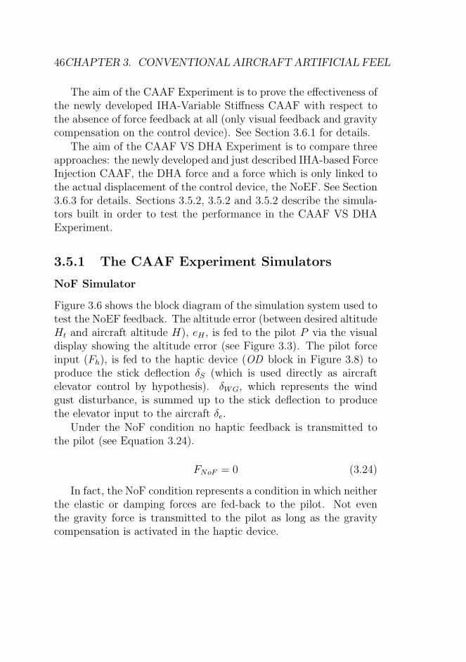
the pilot of the risk to lose aircraft control. Furthermore, externaldisturbances like wind gusts which may be very dangerous if notappropriately and suddenly compensated in a constrained missionenvironment (e.g., a urban canyon), would produce an immediateeffect on the stick. Useful information like load factor, ”distance”from stall and external disturbances cannot be read by the piloton the GCS cockpit instruments; thus the Conventional AircraftArtificial Feel (CAAF) haptic aiding scheme was designed in order toprovide the pilot with a richer information with respect to the visualdisplay only. The experiments were performed in order to show andassess analytically that these additional haptic information help thepilot from a performance point of view.
Level 1 SA (see Section 1.4) says that the pilot needs to ac-curately perceive information about the weather among other ele-ments. Reference [34] followed this principle by creating a hapticsensation linked to the turbulence but in that case the haptic sig-nal was not related to the real sensation experienced by a pilot of amanned aircraft. The present work instead introduces a haptic feed-back which mimics aerodynamic forces usually experienced by thepilots of manned aircrafts and it belongs by definition to the classof IHA because it is born, above all, to improve the SA and it is notdesigned taking into account the right maneuver to perform in orderto reject the wind gust.
As mentioned before, the newly introduced haptic feedback hasbeen given the name of Conventional Aircraft Artificial Feel (CAAF).
Two different version of the CAAF are presented: the former,named Variable Stiffness CAAF, estimates the effect of wind gustas changes in stick stiffness (see Section 3.3.1) while the externalforce, FWG, is set to zero; the latter, named Force Injection CAAF,estimates the effect of wind gust as changes in the angle of attack,α, and dynamic pressure, q, and it produces also an external force,FWG (see Section 3.3.2).
3.3. CAAF 35
3.3.1 Variable Stiffness CAAF
The Variable Stiffness CAAF estimates the effect of wind gust aschanges in stick stiffness according to a weighted sum of the loadfactor, n, and the dynamic pressure, q. Thus, the force was assumedto be dependent on the two most important variables for definingthe flight envelope (see Section A.2 for details). The load factor
n =L
W
is defined as the ratio of the lift L to the weight W of the aircraft,thus it is a measure of the severity of a commanded maneuver. It wasintroduced in the stick force equation to make the pilot more con-scious about the commanded maneuver and to make more difficultthe maneuvers which could be dangerous for the aircraft structureand cause accidents as the loss of wings in the RPV. The externalforce is set to zero:
FCAAF,vs = FSD,vs + FWG,vs
FSD,vs = KS,vs · δS +KD,vs · δS
FWG,vs = 0
(3.15)
FSD,vs is the Spring-Damper component of the force and FWG,vs isthe external force component. The Variable Stiffness CAAF, Equa-tion (3.15), is similar to the Equation (3.13) accept for the null ex-ternal force component, for the introduction of the load factor in thevariable stiffness and for the introduction of a damper component aswell in order to provide some damping for the future implementa-tion of the CAAF in an haptic device. As long as in Equation (3.13)∆δe is the elevator deflection around the trim value, which is 0 degwith the THS deflected by itrim, and fixed on this value and sincethe deflection of the elevator is proportional to the bar deflection formechanically driven aircrafts, in Equation (3.15) δS, the stick deflec-tion, was employed instead of ∆δe. Equation (3.16) shows the valueof the stiffness expression of the Variable Stiffness CAAF:
FCAAF,vs represents the change in the stick force during a ma-neuver with respect to the stick force in trim conditions (Ftrim = 0).δS and δS are stick deflection and stick deflection rate respectively.KD,vs is the damping constant.
The Equation (3.16), shows the changes of the stiffness as pro-portional to the squared velocity, through q, and to the load factor.
Kq,vs and Kn are the weights of the dynamic pressure and of thedifference between the load factor during the maneuver and the oneof horizontal flight respectively (n−1); Kf,vs is a constant gain whichdetermines the ”amount” of force feedback.
The sign conventions are the same as in [47] (see Figure 3.1). Asconcerning the sign, the force that the pilot feels on the stick has thesame sign as the deflection requested to the elevator (see Figure 3.1).Thus, a positive value is needed as Kq,vs. As concerning the dynamicpressure component, the goal is to make the pilot conscious aboutthe velocity of the UAV: the higher is the velocity, the bigger is thedynamic pressure component, the bigger is the spring componentand more difficult will be to perform a maneuver.
As concerning the load factor component: the load factor is pos-itive for climbing maneuver and negative for diving maneuver but apositive sign of the product Kn · (n − 1) is needed, thus Kn shouldhave a negative value for diving maneuvers and a positive value forclimbing maneuvers. The goal of the introduction of the load factorin the spring component of the Variable Stiffness CAAF is to avoidthe pilot doing a sudden maneuver: the higher is the load factor,the bigger is the stiffness of the stick and more difficult will be toperform a maneuver.
In order to assign meaningful values to the constants Kq,vs, Kn
and Kf,vs, the dynamic pressure and the load factor were normalizedwith respect to the max values they can assume. The choice madein Equation (3.17) would satisfy the previous hypothesis:
3.3. CAAF 37
Kq,vs =K′
q,vs1
2ρV 2
max≥ 0, Vmax = Vmd
Kn =
{
K′
n
(n1−1)≥ 0, for n ≥ 1 ⇒ Kn(n− 1) ≥ 0
K′
n
(n2−1)< 0, for n < 1 ⇒ Kn(n− 1) ≥ 0
(3.17)
Furthermore, Kq,vs and Kn can be interpreted as the strain thepilot must exert on the bar to produce a change in velocity or achange in the load factor during a maneuver. In literature [47],something similar to Kn is referred as stick-force-per-g.
Vmd is the velocity maximum of design that was hypothesized tobe the velocity to never exceed, Vne, plus the 10% of the same. n1
and n2 are respectively the positive and negative maximum valuesof load factor of the aircraft.
As concerning K ′n and K ′
q,vs, it could be interesting to find outthe optimal values capable of minimizing a performance index. Thefirst heuristic choice in this work was the value 0.5 for both. As longas the the constants are normalized with respect to the maximumvalues of the variable they weight (q and n), then the value 0.5 meansthat the feel in Equation (3.15) is made up by the changes in q forthe 50%, by the changes in n for the remaining 50%. The quantityin squared parenthesis in Equation (3.16) will assume the value 1 atmaximum. As said, the amount of the feedback force depends by Kf
which scales the stiffness to the desired value. The Federal AviationRegulation (FAR) of the Federal Aviation Administration (FAA)and in particulare the FAR 23 Sect.23.155 impose the strength limitsnecessary to control the elevator for certain values of the load factor,but the real amount of force to employ will depend at the end onthe haptic device maximum output force.
The final expression of the haptic feedback force becomes then:
FCAAF,vs = FSD,vs ·+FWG,vs (3.18)
with FSD,vs and FWG,vs from Equations (3.16) and (3.15). Note
that deltaS and δS of Equations (3.16) and (3.15) were replaced withthe linear xS and xS in Equation 3.18 since the actual control de-vice can only provide end-effector translations. The haptic feedbackexpression of Equation (3.18) was named Variable Stiffness Conven-tional (for mechanically-driven) Aircraft Artificial Feel (CAAF) byits aerodynamically inspired nature. This type of force feedback, inanalogy to what found in the artificial feel literature [75], could beaddressed as a qn-feel system since the force it generates is propor-tional to both dynamic pressure (q) and load factor (n). This forcewas tested through the CAAF Experiment (see Section 3.6.1).
3.3.2 Force Injection CAAF
The Force Injection CAAF of Equation (3.19) estimates the effect ofwind gust as changes in the angle of attack α and of dynamic pressureq and produces an external force. The Force Injection CAAF focuseson the external force component as opposed to the former version(Section 3.3.1) that uses stick stiffness variations. Thus, as long asin the altitude regulation task (object of the experiments in Section3.6) the velocity is close to the one of trim conditions (Vtrim) and theload factor is close to the one of horizontal flight (n = 1), a constantvalue (KS,fi) was chosen as stiffness and the external component,FWG, as in Equation (3.14) was considered:
FCAAF,fi = FSD,fi + FWG,fi
FSD,fi = KS,fi · δS +KD,fi · δS
KS,fi = Kf,fi ·Kq,fi · qtrim
FWG,fi = ηhSeceGe|Ch,α| · q(α− αtrim)(1−dǫdα)
(3.19)
As previously, a damper component with damping constantKD,fi
was added as well in order to provide some damping for the futureimplementation of the CAAF in an haptic device. qtrim is the dy-namic pressure related to the trim velocity, Vtrim.
3.3. CAAF 39
FCAAF,fi represents the change in the stick force during a suddenvertical wind gust. The wind gust affects the angle of attack andmove it away from the angle of attack in trim conditions, αtrim. δSand δS are again the stick deflection and the stick deflection raterespectively.
Kq,fi and Kf,fi are respectively the weight of the dynamic pres-sure and a constant gain which determines the ”amount” of forcefeedback.
As concerning the sign, the force the pilot feels on the stick duringa vertical wind gust has the same sign as the deflection caused tothe elevator by the wind gust. For example a downward wind gustwill create a positive elevator deflection (trailing edge down), a fallin angle of attack (α − αtrim < 0) and so a positive stick deflection(i.e. towards). Thus, the force felt by the pilot is negative (the bartends to move away from the pilot) for downward wing gusts, whileit is positive (the bar tends to move closer to the pilot) for upwardwind gusts. Thus, a positive value is needed as Kq,fi.
As concerning the dynamic pressure component, the goal is tomake the pilot conscious about the change in the velocity of theUAV produced by the wind gust: a downward wind gust produces,as said, a diving maneuver and so a growing velocity and the hapticfeel in Equation (3.19) would suggest that the aircraft is diving anda pilot input in the opposite direction (i.e. moving the bar towardthe pilot) is needed in order to restore the previous trim conditionvalue. The stronger is the gust, the bigger is the change in angleof attack and in the velocity produced, the bigger is the externalforce component and a stronger and clearer information about thepresence of a wind gust will be given to the pilot. An improvementof the situational awareness about the external conditions of theaircraft will be produced. As said, the action requested to the pilotin order to restore the previous trim conditions is to counteract thehaptic feel. This would be a natural reaction to the force for whatSchmidt and Lee proved [77] (see Section 2.2).
In order to assign meaningful values to the constants Kq,fi, Kq,α,Kf,fi andKfWG,fi, the dynamic pressure and the product of dynamicpressure and the change in angle of attack (α−αtrim) were normalizedwith respect to the max values they can assume. The choice madein Equation (3.21) would satisfy the previous hypothesis:
Kq,fi =K′
q,fi1
2ρV 2
max
Kq,α =K′
q,α1
2ρV 2
max·(αst−αtrim),
(3.21)
Furthermore, Kq,fi and Kq,α can be interpreted as the strain thepilot must exert on the bar to produce a change in velocity and achange in the angle of attack a maneuver.
Vmax = Vmd which is defined in Section 3.3.1. αst is the stallincidence of the aircraft.
As concerning K ′q,fi and K
′q,α, it could be interesting to find out
the optimal values capable to minimize a performance indexes. Thefirst heuristic choice in this work was the value 0.5 for both of them.
As long as the the constants are normalized with respect to themaximum values of the variable they weight (q and q · (αst−αtrim)),then the value 0.5 means that the feel in Equation (3.19) is madeup by the changes in q and q · (αst − αtrim) and it is the 50% of themaximum available values. The quantity in squared parenthesis inEquation (3.20) will assume both the value 0.5 at maximum. Theamount of stiffeness and the amount of the external force dependby KfS,fi and KfWG,fi respectively. They scale the stiffness and theexternal force FWG,fi to the desired value. Their choice was madeheuristically by taking into account the haptic device maximum out-put force.
3.4. THE EXPERIMENTAL SETUP 41
The final expression of the haptic feedback force is representedby the Equation (3.20) and was named Force Injection Conventional(for mechanically-driven) Aircraft Artificial Feel (CAAF) by its aero-dynamically inspired nature. This type of force feedback, in analogyto what found in the artificial feel literature [75], could be addressedas a qα-feel system since the force it generates is proportional toboth dynamic pressure (q) and angle of attack (α). This force wastested through the CAAF VS DHA Experiment (see Section 3.6.3).
Dickinson noted that ”in particular we can take the opportunityof making control forces do what we desire them to do rather thanhaving to accept the consequences of fundamental laws as hitherto”[75]. Thus from now on, the mentioned opportunity was taken byusing heuristical stiffness, damping constants and external forces in-stead of using constants (as in Equations (3.17) and (3.21)) whichdepend from the particular aircraft under consideration. This wouldmake the haptic force to be transportable because created on thehuman being feeling instead of the particular aircraft (remotely ornot) piloted.
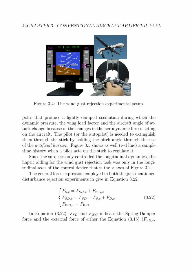
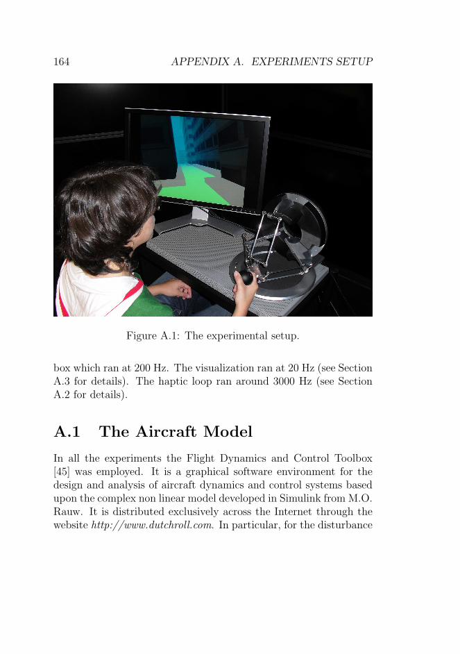
3.4 The Experimental Setup
In order to test the CAAF concepts exposed in Sections 3.3 and 3.5,a simulated flight experiment was set-up. A fully non linear air-craft simulator was used to provide a realistic aircraft response. Anaircraft simulator was implemented using a Matlab/Simulink sim-ulation. The selected aircraft model was a De Havilland CanadaDHC-2 Beaver implemented using the Flight Dynamics and ControlToolbox [45].
The selected haptic device is the widely used Omega Device inFigure 3.2 (omega.3, Force Dimension, Switzerland) which was cho-sen in order to simulate a control column of a mechanically drivenaircraft. It is a 3DOF high precision force feedback device whichprovides control stick simulated force up to 12 N (See Section A for
A simulated Electronic Flight Instrument Display (Figure 3.3)was used during the experiments to produce the visual cues. It isa reproduction of a real one as it was designed to be as similar aspossible to conventional aircraft head-down display (see Section Afor details on the EFIS Display implementation). The display showsthe relevant variables in the task (pitch, altitude, speed) and thevariable to be regulated (altitude) with a magenta reference markfor the set point 300ft for altitude.
Figure 3.4 shows the experimental test bed comprising of a videodisplay and the haptic device.
The only dynamics considered in this Chapter is the longitudinalone. In order to control the longitudinal dynamics, the pilot usuallyacts on the thrust and on the elevator. In the present work, theelevator deflection is, by hypothesis, the only input provided to thesimulated aircraft. This is a reasonable choice as long as the presentwork is an artificial feel study. In fact, acting on thrust and on theelevator at the same time would be reasonable for an autopilot or aStability Augmentation System (SAS) study. Acting on thrust and
3.4. THE EXPERIMENTAL SETUP 43
10 10
0 0
-10 -10
10
10
20
20
0
0
-10
-10
130REF
320
310
300
290
280
270
260
240
230
250
300250
30 60
40 50
250H
1
1
2
3
2
3
Figure 3.3: The Electronic Flight Instrument System Display.
on the elevator at the same time is also usually useless or undesirable,even on a real aircrafts (i.e. during the takeoff in which it occurs topull-up the aircraft through the elevator with the maximum thrust).Furthermore, acting only on the elevator to pull-up the aircraft is atraditional piloting maneuver.
In this work, the elevator deflection is proportional to the dis-placement δS of Equations (3.15) and (3.15). δS is the input tothe aircraft generated by the operator by moving the Haptic Deviceend-effector in the x-direction (see Figure 3.2).
An input on the elevator, starts the natural longitudinal air-craft modes: the Phugoid and the Short Period modes (see SectionA.1.2). It causes a dynamic transient phase because of the exchangesbetween kinetic and potential energy and oscillations in the aircraftlongitudinal variables (velocity, pitch angle, altitude, etc) around thecenter of gravity start. In Figure 3.5 the mentioned natural modesare shown (blue line).
In Figure 3.5 the Phugoid is the most visible oscillation, while theshort period oscillation has, as the name suggests, a shorter periodand, since it has usually a big damping constant, it disappears verysoon. The Phugoid mode is characterized by complex and conjugate
Figure 3.4: The wind gust rejection experimental setup.
poles that produce a lightly damped oscillation during which thedynamic pressure, the wing load factor and the aircraft angle of at-tack change because of the changes in the aerodynamic forces actingon the aircraft. The pilot (or the autopilot) is needed to extinguishthem through the stick by holding the pitch angle through the useof the artificial horizon. Figure 3.5 shows as well (red line) a sampletime history when a pilot acts on the stick to regulate it.
Since the subjects only controlled the longitudinal dynamics, thehaptic aiding for the wind gust rejection task was only in the longi-tudinal axes of the control device that is the x axes of Figure 3.2.
The general force expression employed in both the just mentioneddisturbance rejection experiments in give in Equation 3.22:
FS,x = FSD,x + FWG,x
FSD,x = FSD = FS,x + FD,x
FWG,x = FWG
(3.22)
In Equation (3.22), FSD and FWG indicate the Spring-Damperforce and the external force of either the Equation (3.15) (FSD,vs
3.5. DISTURBANCE REJECTION EXPERIMENTS 45
20 40 60 80 100 120
290
295
300
305
310
315
time [s]
Alti
tude
[m]
natural modepilot damped mode
Figure 3.5: Response to elevator impulse input: Phugoid and ShortPeriod natural aircraft modes (blue line) versus the typical aircraftresponse damped by a good pilot (red line).
and FWG,vs) or the Equation (3.19) (FSD,fi and FWG,fi).
Fx = KS,x · xS +KD,x · xS + FWG (3.23)
Then, the force Fx felt by the operator during the wind rejectiontask (see Equation (3.22) and (3.23)) along the control device x axes(see Figure 3.2) is a combination of an elastic term, FS,x (KS,x · xS),with constant stiffness KS,x, a damping term, FD,x (KD,x · xS), witha damping constant KD,x (refer to the Table A.2 for the values used)and an external force component FWG. xS and xS are the longitu-dinal displacement and displacement rate of the end-effector respec-tively.
3.5 Disturbance Rejection Experiments
Two experiments within the specific field of Remotely Piloted Ve-hicles control in a disturbance rejection task were run: the CAAFExperiment and the CAAF VS DHA Experiment.
The aim of the CAAF Experiment is to prove the effectiveness ofthe newly developed IHA-Variable Stiffness CAAF with respect tothe absence of force feedback at all (only visual feedback and gravitycompensation on the control device). See Section 3.6.1 for details.
The aim of the CAAF VS DHA Experiment is to compare threeapproaches: the newly developed and just described IHA-based ForceInjection CAAF, the DHA force and a force which is only linked tothe actual displacement of the control device, the NoEF. See Section3.6.3 for details. Sections 3.5.2, 3.5.2 and 3.5.2 describe the simula-tors built in order to test the performance in the CAAF VS DHAExperiment.
3.5.1 The CAAF Experiment Simulators
NoF Simulator
Figure 3.6 shows the block diagram of the simulation system used totest the NoEF feedback. The altitude error (between desired altitudeHt and aircraft altitude H), eH , is fed to the pilot P via the visualdisplay showing the altitude error (see Figure 3.3). The pilot forceinput (Fh), is fed to the haptic device (OD block in Figure 3.8) toproduce the stick deflection δS (which is used directly as aircraftelevator control by hypothesis). δWG, which represents the windgust disturbance, is summed up to the stick deflection to producethe elevator input to the aircraft δe.
Under the NoF condition no haptic feedback is transmitted tothe pilot (see Equation 3.24).
FNoF = 0 (3.24)
In fact, the NoF condition represents a condition in which neitherthe elastic or damping forces are fed-back to the pilot. Not eventhe gravity force is transmitted to the pilot as long as the gravitycompensation is activated in the haptic device.
3.5. DISTURBANCE REJECTION EXPERIMENTS 47
P OD UAVδSFh
+Ht eH
-δe H
δWG
Figure 3.6: NoF simulator scheme.
Suppose a wind gust affects the aircraft: as long as FSD,x, FWG =0 in the Equation (3.22), no force is directly linked either to the windgust or to the actual end-effector displacement. Thus, the pilot willnot feel through the sense of touch any haptic information aboutboth the position of the control device end-effector and the presenceof wind gust but he will just see the altitude changing through thevisual display, an Integrated Flight Display (see Figure 3.3). Thevisual feedback is the same in all the conditions of the experiment.
IHA-Variable Stiffness CAAF Simulator
Figure 3.7 shows the block diagram of the simulation system used totest the IHA-Variable Stiffness CAAF feedback. The altitude error(between desired altitude Ht and aircraft altitude H), eH , is fed tothe pilot P via the visual display showing the altitude error (seeFigure 3.3). The pilot force input (Fh), is fed to the haptic device(OD block in Figure 3.8) to produce the stick deflection δS (whichis used directly as aircraft elevator control by hypothesis). δWG,which represents the wind gust disturbance, is summed up to thestick deflection to produce the elevator input to the aircraft δe.
Under the this condition the haptic feedback of Equation (3.18)is transmitted to the pilot.
Suppose a wind gust affects the aircraft: the pilot, while dampingthe phugoid mode, will feel a force feedback proportional to the
changes in the dynamic pressure and in the load factor according tothe Equation (3.18) and will the same visual feedback as in the NoFcondition.
3.5.2 The CAAF VS DHA Experiment Simula-tors
IHA-Force Injection CAAF Simulator
Figure 3.8 shows the block diagram of the simulation system used totest the IHA concept. The altitude error (between desired altitudeHt and aircraft altitude H), eH , is fed to the pilot P via the visualdisplay showing the aircraft speed and altitude (see Figure 3.3). Theaircraft speed (V ), used to compute the dynamic pressure, and theangle of attack (α) are fed to the Haptic device that implementsthe CAAF-IHA law and feeds-back the force (FWG) as in Equations(3.19) and (3.20) which, together with the pilot force input (Fh), isfed to the haptic device (OD block in Figure 3.8) to produce thestick deflection δS (which is used directly as aircraft elevator controlby hypothesis). δS and δS indicate that pilots actually feels theelastic and damping haptic device response. δWG, which representsthe wind gust disturbance, is summed up to the stick deflection toproduce the elevator input to the aircraft δe.
Under this condition the haptic feedback of Equation (3.20) istransmitted to the pilot.
Suppose a downward wind gust affects the aircraft: the angle ofattack of the aircraft decreases with respect to the trim condition,the dynamic pressure changes (possibly very lightly depending on thegust speed with respect to the aircraft speed) and the altitude tendsto decrease. Within this condition, the CAAF-IHA law produces anegative force, FWG, that would produce a positive stick deflection,δS, and thus induces the aircraft to dive even more. The force isimmediately felt by the pilot who knows that something has changed.In this specific case the pilot feels a force that pulls the stick awayfrom him, that is to dive, and he should react immediately, accordingto his experience, by opposing to the stick motion in order to keepthe altitude constant. This type of force feedback, roughly speakingwith opposite sign with respect to the actual maneuver to be taken,is in complete accordance with the IHA concept.
Figure 3.9 depicts an example of the variables history during asimulation trial.
Figure 3.10 shows the block diagram of the simulation system usedto test the NoEF feedback. The altitude error (between desiredaltitude Ht and aircraft altitude H), eH , is fed to the pilot P via thevisual display showing the aircraft speed and altitude (see Figure3.3). The pilot force input (Fh), is fed to the haptic device (ODblock in Figure 3.8) to produce the stick deflection δS (which isused directly as aircraft elevator control by hypothesis). δS and δSindicate that pilots actually feels the elastic and damping hapticdevice response. δWG, which represents the wind gust disturbance,is summed up to the stick deflection to produce the elevator inputto the aircraft δe.
The NoEF condition presents a constant stiffness stick (KS,fi inTable A.2 and simulates a fly-by-wire like situation. In the NoEFcondition the force exerted by the haptic device is the same (i.e. the
3.5. DISTURBANCE REJECTION EXPERIMENTS 51
P OD UAVδSFh
H
+Ht eH
-δe
δWG
δS
.
Figure 3.10: NoEF simulator scheme.
same Spring-Damper component) as in the Equation (3.19) exceptfor FWG,fi which is set to zero in this condition. The pilot had anIntegrated Flight Display as the only instrument showing the aircraftspeed and altitude (see Figure 3.3). The visual feedback is the samein all the conditions of the experiment.
Under the NoEF condition, the haptic feedback of Equation 3.25is transmitted to the pilot.
FNoEF = FSD,x (3.25)
Suppose a wind gust affects the aircraft: as long as FWG = 0in the Equation (3.19), no force is directly linked to the wind gust.Thus, the pilot will not feel any haptic information about the pres-ence of wind gust but he will just see the altitude changing throughthe visual display. The only haptic feedback felt by the pilot is pro-portional to δS and δS produced only by the pilot input force Fh.
Figure 3.11 depicts an example of the variables history during asimulation trial.
Compensator-Based DHA Simulator
In order to compare the three approaches, a DHA-based simulatorwas designed. According to the DHA definition, a Direct HapticAiding system for wind gust rejection should produce a force or achange in stiffness that helps the pilot directly in achieving the task
that is in this case to reject the gust. Thus, a system that pro-duces a force which pulls the stick in the same direction the pilotshould do to reject the disturbance, seems appropriate for a DHAcontrol. As a matter of fact, the obstacle avoidance system describedin [1, 78] works exactly according to this principle. Stiffness varia-tion, together with force feedback were investigated and found to beable to provide better results than single stiffness or force feedback[78]. Nevertheless, for the purposes of this comparison, we decidedto investigate and compare force feedback only. A compensator wasadded to compute the external force to be felt by the pilot. TheHaptic device was controlled as in Equation (3.19) to behave as aspring-damper system with an additional force FWG which is gener-ated by the DHA compensator (see later).
Figure 3.12 shows the block diagram of the simulation systemused to test the DHA concept. The altitude error (between desired
3.5. DISTURBANCE REJECTION EXPERIMENTS 53
altitude Ht and aircraft altitude H), eH , is fed to the pilot P via thevisual display showing the aircraft speed and altitude (see Figure3.3). The altitude error, eH , is also fed to the DHA block thatimplements the DHA force and feeds-back the force (FWG) which,together with the pilot force input (Fh), is fed to the haptic device(OD block in Figure 3.12) to produce the stick deflection δS (whichis used directly as aircraft elevator control by hypothesis). δS andδS indicate that pilots actually feels the elastic and damping hapticdevice response. δWG, which represents the wind gust disturbance,is summed up to the stick deflection to produce the elevator inputto the aircraft δe.
P OD UAVδSFh
H
+Ht
eH
DHA
-δe+
+
δWG
δS
.
FWG���A
Figure 3.12: Compensator-Based DHA simulator scheme.
The DHA block in Figure 3.12 is a compensator represented bythe transfer function of Equation (3.26) which calculates the DHAexternal force starting from the altitude error. It was designed inorder to damp the Phugoid mode as a good pilot would do and cancelthe Omega Device dynamics (see Section C.1). In order to designto DHA compensator, the Omega Device dynamics was identified(see Section B for details). The net result is that such compensatorcan damp effectively the Phugoid mode from altitude measurementby itself, without any pilot in the loop: the stick moves and thecorresponding stick deflection is sufficient to control the aircraft. Inorder to leave the pilot with sufficient control authority, the gain of
Thus, the force felt in DHA case is given from Equation (3.19)by considering FWG,fi = FWG,DHA of the Equation (3.26):
FDHA = FSD,x + FWG,DHA (3.27)
Thus, the Spring-Damper component, FSD,fi, is the same in eachof the three force conditions (NoEF, IHA and DHA). Suppose adownward wind gust affects the aircraft: the altitude tends to de-crease. Within this condition, the DHA compensator produces apositive force, FWG, that would produce a negative stick deflection,δS, and thus induces the aircraft to climb back to the target altitude(the initial one). In this specific case the pilot feels a force that pullsthe stick toward him, that is to climb, and he should be compliantwith the force, by following and amplifying the stick motion, in or-der to keep altitude constant. This type of force feedback, roughlyspeaking with the same sign with respect to the actual maneuver tobe taken, is in complete accordance with the DHA concept.
Figure 3.13 depicts an example of the variables history during asimulation trial.
The design of a DHA based augmentation scheme seems to bevery task dependent; the compensator-based design approach de-scribed above was viable in our case since the task was specifiedas holding a reference altitude. This approach could not be usedinstead when the task cannot be specified as a reference signal tobe tracked, or the pilot intention is not known; thus the design ofa DHA augmentation scheme could be less straightforward than anIHA scheme.
The Section 3.6 present the experimental evaluation of the CAAFconcepts.
3.6. CAAF EVALUATION 55
0 10 20 30 40 50 60
−20
−10
0
10
20
30
time [s]
δWG
impulse [cm]
FDHA
[N]
FWG,DHA
[N]
Altitude Error [ft]
Figure 3.13: DHA simulation example.
3.6 CAAF Evaluation
This Section present the experimental evaluation of the conceptsdescribed in Sections 3.3 and 3.5. In particular, the Section 3.6.1describes the CAAF experiment and results and the Section 3.6.3describes the CAAF VS DHA experiment and results.
3.6.1 CAAF Experiment
In the CAAF Experiment, object of this section, a simple regulationtask was prepared: the aircraft is initially flying leveled in trimmedcondition (300 ft altitude) and at constant altitude; at a certaintime, a disturbance (elevator impulse) is artificially injected, andthe aircraft initiates a motion according to its Phugoid mode.
The pilot’s task is to keep the aircraft leveled, non oscillating,to restore the initial altitude and to keep it as constant as possible.
During this task, the pitch and altitude oscillations of the Phugoidmode have to be damped by the pilot using the stick (as the red linein Figure 3.5).
The goal of these tests is to proof whether adding the VariableStiffness CAAF kinesthetic (force) cue to the visual cue (a simulatedcockpit) improves the control. In particular the goal is to assess asanalytically as possible the differences in pilot performance in the twocases: with and without Variable Stiffness CAAF; the performanceof the subjects (dependent variable) was measured through the IAE(Integral Absolute Error) between the current and desired altitude;a smaller IAE would indicate a better pilot performance in dampingthe Phugoid mode.
Eighteen naive subjects (aged 23 to 43, mean 30.7) participatedto the experiment. All had normal or corrected-to-normal vision.They were paid, naive as to the purpose of the study, and gave theirinformed consent. The experiments were approved by the EthicsCommittee of the University Clinic of Tubingen, and conformed withthe 1964 Declaration of Helsinki. The experiment consisted of threedifferent force conditions: No Force condition, with only compensa-tion of gravity activated on the end-effector, Simple Force condition,the Variable Stiffness CAAF of Equation (3.15), and the DoubleForce condition, twice as much force as in the Simple Force condi-tion, achieved by doubling the Kf,vs gain. Each condition was runas a separate block, i.e., the experiment consisted of three successiveblocks. The order of presentation of the blocks was counterbalanced(see Section D.2 for details).
In total, the experiment lasted from 60 to 90 minutes (includinginstructions and breaks between blocks).
3.6.2 CAAF Experimental Results
Mean IAE values were entered in a one-way repeated measures anal-ysis of variance (ANOVA) [NoF, IHA-VS CAAF, IHA-Double VS
3.6. CAAF EVALUATION 57
CAAF] (VS is for Variable Stiffness), which revealed a significanteffect of the force factor
[F (2, 34) = 7.932, p < 0.01]
As shown in Figure 3.14, the participants were the least variable(performed best) when a simple force was applied, the most variable(performed worst) when no force was applied, whereas providing adouble force gave rise to ’intermediate’ results.
0 1 20
100
200
300
400
500
600
IAE
[ft*
s]
NoFIHA−CAAF
vs
IHA−Double CAAFvs
Figure 3.14: Performance (mean and standard error) for the threeForce conditions (NoF, IHA-VS CAAF, IHA-Double VS CAAF).
Post-hoc tests using Bonferroni correction for multiple compar-isons (p < 0.05) indicated that the performance with force (bothSimple and Double) was significantly less variable than without force.In other words, providing Variable Stiffness CAAF force significantlyimproved piloting performance as it reduced the variability of thecontrol. We also assessed the effect of the order of presentation ofthe blocks with a one-way repeated measures ANOVA [First Block,Second Block, Third Block], which revealed no significant main ef-fect of the order of presentation. In other words, the variability of
the performance was comparable irrespective of the order of presen-tation.
Our results clearly show that the Variable Stiffness CAAF facil-itates control in this task. Indeed, participants’ performance signif-icantly improved when haptic cueing was available. As none of theparticipants had any experience with piloting, our results suggestthat this type of aiding is rather ’natural’, as beneficial effects can beobserved without any previous learning. In line with these convinc-ing initial results, could be interesting as future work to investigatethe amount of additional information transferred to the operator viathe CAAF variable stiffness haptic feedback as compared with othertypes of haptic aids (e.g., constant stiffness).
3.6.3 CAAF VS DHA Experiment
In the CAAF VS DHA Experiment, object of this section, a simplecontrol task was prepared: the aircraft was initially flying leveled intrimmed condition at constant altitude (300 ft); three severe verticalwind gusts, which induce the aircraft to initiate a motion accordingto its Phugoid mode, are simulated by artificially injecting threecontrol disturbances (elevator impulses) of randomized duration (2,3 or 3.5 seconds), starting time and sign (upward or downward).
During this task, the pitch and altitude oscillations of the Phugoidmode have to be damped by the pilot through the use of the stick.
When a vertical wind gust disturbance affects a manned aircraft,the change in angle of attack and wing load are practically instan-taneous. This has also an immediate effect on a mechanical-linkagebased control stick. The altimeter on the GCS cockpit will thoughshow the resulting change in altitude with a certain delay with re-spect to the actual disturbance time; as a matter of fact the aircraftdynamics has a low pass behavior and phase lag from angle of at-tack to altitude (in the simplest linear approximation it behaves asan integrator).
3.6. CAAF EVALUATION 59
In order to focus on the haptic cueing we made the experimentmore difficult for the pilots by setting the Artificial Horizon inop-erable (zero pitch and roll); only altitude and speed readings weredisplayed.
The experiment consisted of three different external force con-ditions: No External Force condition (referred as NoEF condition)with only the spring-damper force on the end-effector, IHA condi-tion (the Force Injection CAAF from Equation (3.19)) and DHAcondition (see the Section 3.5.2 for details).
All the trials have been mixed and counter-balanced (see SectionD.2 for details) and no instructions were given about the three dif-ferent force conditions to test natural reaction of the pilots to thethree different conditions.
A test campaign with a professional pilots was performed for thealtitude regulation task. Seven professional pilots (from 50 to 700hours of flight experience) participated to the experiment. The goalof these tests is to proof whether adding the IHA-Force InjectionCAAF kinesthetic (force) cue or the DHA kinesthetic (force) to thevisual cue (the simulated cockpit), improves the control with respectto a simple spring-damper behavior of the stick (NoEF). In particularthe goal is to assess as analytically as possible the differences in pilotperformance in three cases identified as NoEF, IHA-Force InjectionCAAF, DHA. The performance of the subjects (dependent variable)was measured through the IAE (Integral Absolute Error) betweenthe current and desired altitude; a smaller IAE would indicate abetter pilot performance in damping the Phugoid mode.
All the trials (36 of 60 seconds each, 12 trials per condition) havebeen mixed and counter-balanced to test natural reaction of the pi-lots to the three different conditions. Before starting the experiment,every pilot was asked to run a 5 minutes trial where he/she had toperform a slightly different altitude regulation task; the goal of thisinitial trial, was to let the pilot acquire enough knowledge of aircraftdynamics to be able to pilot it confidently. During this trial a sim-
ple spring-damper behavior of the stick was employed. In total theexperiment lasted 90 minutes. All pilots had normal or corrected-to-normal vision; they were paid and gave their informed consent. Theexperiments were approved by the Ethics Committee of the Univer-sity Clinic of Tubingen, and conformed with the 1964 Declaration ofHelsinki.
3.6.4 CAAF VS DHA Experimental Results
To summarize the forces felt by the pilots during the experiment anexample is given: when a vertical wind gust (upwards for example)affects the aircraft, it will climb. The pilot should push over in orderto reject the gust. So, to reject the gust the pilot should be compliantwith the DHA Force and should oppose to the IHA Force.
As concerning the experimental results: mean IAE values for thethree force conditions [NoEF, IHA, DHA] were entered in a one-wayrepeated measures analysis of variance (ANOVA). When all trials(12 trial for each condition) were considered, no main effect of thetype of force was observed, i.e., the three types of force did not differfrom one another. We then assessed whether all three types of forcefeedback were equally ’natural’ for the subjects, i.e., whether the firstexposure to the different types of feedback gave rise to comparableperformance. Here, only the first two trials of each subject for eachcondition were considered, and the data were entered in the sameone-way ANOVA (described above). This analysis revealed a maineffect of the type of force feedback
[F (2, 12) = 12.943, p < 0.01]
As shown in Figure 3.15, the participants were the least variablein the NoEF and IHA conditions, and the most variable when theDHA force was applied, the variability being significantly worse inthis last condition (post-hoc tests using Bonferroni correction formultiple comparisons, p < 0.05). In other words, when completely
3.6. CAAF EVALUATION 61
naive about the aiding schemes (in the first two trials), participantsperformed significantly better when either no force or the IHA aidingscheme was used than with the DHA aiding scheme.
0 1 20
200
400
600
800
1000
IAE
[ft*
s]
NoEF
IHA−CAAFfi
DHA
Figure 3.15: Performance (mean and standard error) for the 3 Forceconditions of the first 2 trials.
Assuming that a certain degree of adaptation and learning of thepilots could have happened during the 12 trials, we also evaluatedseparately the last five trials of each condition. To test whether thiswas the case, the mean values of the last five trials were entered inthe same one-way ANOVA. The analysis revealed a main effect ofthe type of force feedback
[F (2, 12) = 13.007, p < 0.001]
As shown in Figure 3.16, the participants were the least variablewhen the DHA force was applied, and the most variable when bothNoEF and IHA forces were applied. Post-hoc comparisons usingBonferroni correction (p < 0.05) showed that this difference was sig-nificant. In other words, after some training, the DHA approachallowed the best results. It is worth noticing that, the pilot were not
trained explicitly on the three force conditions, and that the trialsconsisted of a sequence of mixed conditions and not of a uniformbatch of the same force condition; thus no explicit training was pro-vided to the pilots on any of the three conditions, but the pilot werequickly capable to understand the DHA functionality and exploit itfor improving their performance.
0 1 20
50
100
150
200
250
300
350
IAE
[ft*
s]
NoEFIHA−CAAF
fi
DHA
Figure 3.16: Performance (mean and standard error) for the 3 Forceconditions of the last 5 trials.
After each experiment, pilots were interviewed separately; first ofall the pilots were asked to describe their experience and identify thenumber of different types of sensations they felt during the exper-iment. All of them identified mainly two classes of force feedback:one which they called ”natural”, another which they called ”autopi-lot” as they realized, after few tests (from 2 to 4), that in certainexperiments the system was providing forces that where oriented inthe direction of helping to perform the maneuver (autopilot case)and in other cases the forces were easier to associate with what theywere expecting as the aircraft behavior (natural case). Only onepilot realized that some trials were run with the no force case inwhich the external disturbances give no sensation trough the stick.
3.6. CAAF EVALUATION 63
Thus, in order to compare the results, each pilot was asked to fillin a questionnaire with 6 questions (Table 3.1). In each questionhe/she had to choose, accordingly to the classification of sensationsdescribed above, between two different force feedback cases: ”Natu-ral” and ”Autopilot”. According to the discussions with the pilots,we are confident that the Natural case can be mapped to the unionof the NoEF and IHA cases, while the Autopilot case maps to theDHA condition. The 6 questions in the questionnaire are shown inthe Table 3.1:
A. Which force condition was stronger?B. Which of the two conditions do you think was more helpful?C. Under which condition you think you had the best control on
the aircraft?D. In which condition you think you had to produce the largest
effort?E. In which of the condition you think you had the best perfor-
mance?F. Which of the conditions did you prefer?
Table 3.1: The wind gust rejection task questionnaire.
Figure 3.17 shows the corresponding pilot answers. Most pilotsagree that the Autopilot case presented stronger forces and was morehelpful (Questions A and B) with respect to the Natural case. An-swers to question B and C show a controversial situation: althoughmost pilots voted for the Autopilot as the most helpful, most pilotsfelt more like being actually piloting the aircraft (Question C) withthe Natural case. Pilots’ opinions about the workload (QuestionD) and about the evaluation of their own performance in the task(Question E) were divided. Finally, although it could appear thatpilots were going to prefer the Autopilot case, most of them voted forthe Natural case. With respect to the latter question, the pilot whovoted ”not sure” said that he would have voted for the Autopilot
We can conclude that the NoEF and IHA case are the mostnatural forces to the pilots while after some training they can adaptto the DHA force feedback producing the best results even if theworkload in this case results to be greater than in the previous cases.
Chapter 4
Obstacle Avoidance Feel
According to [10], the haptic feedback can compensate to some ex-tent for the lack of sensory cues that will be presented to UAV opera-tors (see Section 1.3), this means that a way improve the situationalawareness of a remote UAV pilot and the efficiency of the teleoper-ation is the addiction of a haptic interface to the usually employedvisual interface. It seems to be particularly necessary in cases of lim-ited visual information. In the presence of foggy weather conditions,for example, or because of the employment of a limited FOV camera[1], the haptic feedback could provide information through the senseof touch, which can be applied directly on the control device.
In Section 2.2 a classification about the haptic aids of literaturewas given. The haptic aids were classified in DHA and IHA. Most ofhaptic literature is based on DHA concept. In particular, as concern-ing obstacle avoidance task every existing haptic aid seems to belongto the DHA class. Usually in this class, repulsive force is associatedto the obstacles. Thus the pilot (or the teleoperator in general) hasto be compliant with the force felt on the remote controller. In thisChapter, an attempt of designing a force feedback for the obstacleavoidance task which belongs to the IHA class was made. This willbe shown to result more ”natural” then the usually employed DHA-
65
66 CHAPTER 4. OBSTACLE AVOIDANCE FEEL
based approaches. This would confirm what Schmidt and Lee [77](see Section 2.2).
The research resulted in an obstacle avoidance/detection forcenamed IHA-Obstacle Avoidance Feel (IHA-OAF) and it is the objectof the present Chapter. It will be shown to definitely improve thepilots’ sensations and performance!
4.1 Simulation Environment
The present Section describes in details the simulation environmentof the obstacle avoidance task.
Figure 4.1 shows the setup employed in the experiment. The vir-tual environment display produces the visual cue; a subjective viewfrom the aircraft cockpit was simulated using a realistic virtual envi-ronment created using the DynaWORLDS software package [42] (seeSection A.3 for details on the implementation). The environmentwas constituted by a non-Manhattan scenario (see Figure D.3) witha ground plane, the sky and buildings with regularly spaced win-dows to reproduce an appropriate perception of depth. As a matterof fact, the teleoperation of a vehicle in a opened area makes the sim-ulation less problematic than the implementation of a constrainedenvironment as long as, in the latter case, an accidental reductionof the visual feedback or small delays could bring to collisions. Theobstacle avoidance task is a challenging problem in robotics.
To make the implementation of the experiment easier, the fullnon linear dynamics previously mentioned (DHC-2 Beaver [45]) waslinearized around the trim conditions (horizontal flight at 300 ft al-titude). As concerning the obstacle avoidance task the aircraft dy-namics was decoupled and only the lateral dynamic was considered.The Equation (3.5) shows how the elevator deflection through thechanges of the lift coefficients modifies the aircraft lift and thus thelongitudinal aircraft trajectory. It concerned the longitudinal dy-namics. As concerning the lateral dynamics, something similar to
4.1. SIMULATION ENVIRONMENT 67
Figure 4.1: The obstacle avoidance teleoperation setup.
Equation (3.5) can be written.
In order to limit pilot workload and possible errors, only theaircraft lateral dynamics (i.e. roll and heading angles and lateralposition) had to be controlled by the pilot. Equation (4.1) showsthe lateral steady state equations of horizontal flight in Wind Axes(see Section 3.2.2 for the definition) [48]:
0 = C = CC · qS
0 = l = Cl · bqS
0 = n = Cn · bqS
(4.1)
where C, l and n are respectively the aircraft cross-wind force, therolling and the yawing moments; CC , Cl and Cn are respectively theaircraft cross-wind force, rolling and yawing moment coefficients. bis the wing span. Similarly to Equation (3.5), the coefficients presentin Equation (4.1) can be re-written as proportional to the sideslipangle β, the angle between the aircraft direction of the motion (therelative speed) and the x-axis in the Body Reference Frame (seeSection 3.2.1 for the definition), and to the aileron deflection δa (the
68 CHAPTER 4. OBSTACLE AVOIDANCE FEEL
rudder deflection δr and α are supposed to be fixed in the respectivetrim condition values). The only input to the lateral dynamics isthe aileron deflection δa. The employed haptic device is again theOmega Device (see Section 3.4) and a lateral deflection, δA, of itsend-effector was hypothesized to produce the aircraft lateral motion.See the following Section for details on the lateral linear dynamicmodel of the aircraft employed.
4.2 Aircraft Lateral Dynamics
Figure 4.2 shows the baseline scheme (i.e. no haptic aids) employedin the obstacle avoidance setup.
P OD UAV(s)Fh δA = δa
δA
.
pCG,ϕ,ψE
Visual
Display
Figure 4.2: The obstacle avoidance simulation baseline scheme.
The input of the aircraft lateral dynamics UAV (s) is the ailerondeflection, δa, (in this Chapter coincident with the deflection δA ofthe haptic device represented by the OD block) and the outputsare the aircraft center of gravity position pCG or (xe, ye), heading(ψ) and roll angle (φ) of the aircraft in the Earth Reference Frame(Earth-Centered, Earth-Fixed reference frame with origin in the cen-ter of the Earth, zOB axis points North, xOB and yOB axes are onthe equatorial plane). The block UAV (s) in Figure 4.2 is shown indetails in Figure 4.3.
In Figure 4.3 the transfer function HUAV (s) (4.2) (from aileron,δa, to roll rate, p or φ) was employed. It is obtained from linearization
4.2. AIRCRAFT LATERAL DYNAMICS 69
pHUAV(s) 1/s
δa ϕTC
r1/s
ψFBE
xe,ye1/s
xe,ye. .
ψ
ϕ
Figure 4.3: The aircraft lateral dynamics.
of the non linear Beaver DHC-2 of the Flight Dynamics and ControlToolbox [45]. The roll angle, φ, is obtained through integration andsaturated to 50 degrees to make the aircraft dynamics more realistic.
HUAV (s) =−9s4 + 9.8777s3 + 10.413s2 − 6.1385s+ 0.018381
s4 + 8.1578s3 + 10.2490s2 + 11.8186s+ 0.6961(4.2)
Then, by making the assumption of aircraft performing a coordi-nated turn [47] (TC block in Figure 4.3) (zero velocity in the lateralbody axes) at constant speed V (about 50 m/s), the heading rate ror ψ is calculated through the Equation (4.3):
ψ = r = tan(φ)g
V(4.3)
where g is the gravity acceleration. The heading angle, ψ, isobtained by integration. xe and ye are calculated by a coordinatestransformation (FBE block) of Equation (4.4) from Body ReferenceFrame to Earth Reference Frame (see the Section 3.2.1 and abovefor the reference frames definitions).
[
xeye
]
=
[
cos(ψ)sin(ψ)
]
V (4.4)
The coordinates of the aircraft center of gravity (xe and ye) arecalculated from Equation (4.4) by integration. As shown in Figure4.2, informations about the environmental constrains (contained inE block) are used to show through the Visual Display (see Figure
70 CHAPTER 4. OBSTACLE AVOIDANCE FEEL
4.1) the virtual environment from the camera point of view which isrepresented by the aircraft center of gravity position and attitude.
4.3 The Stick Force
Since, as hypothesis, the only dynamics to control is the lateral one,the haptic aid for the obstacle avoidance task was applied only tothe lateral axes of the control device that is the y axes in Figure 3.2.
Thus, the only force transmitted to the operator is along the yaxis.
Fy = FSD,y + FOA,y
FSD,y = FSD = FS,y · yS + FD,y · yS
FOA,y = FOA
(4.5)
In Equation (4.5), FSD is the Spring-Damper force. The lateralstiffness and damping components, FS,y and FD,y, were chosen as inTable A.2. The lateral stiffness is a half of the longitudinal stiff-ness. As a matter of fact, as concerning the force and displacementcharacteristics, the sticks have usually stiffer gradients pitching com-mands (forward/backward arm movement) than for roll commands(left/right arm movements) [82] because of the differences in strengthamong the various arm muscles used for pitch and roll control. Sim-ilar difference exists between pulling movements (both longitudinaland lateral) towards the pilot body and pushing movements awayfrom it [82] but in this work the stiffness is supposed to be constantfor both longitudinal and lateral movements although the differentvalues (smaller for lateral stick displacements).
The Spring-Damper term depends on the desired stick dynamicsand it is present (same value) in all the conditions of the experiment,while the external force term for the obstacle avoidance, FOA, de-pends on the experimental conditions. Three types of external forceFOA have been compared: DHA, IHA and a baseline force condition
4.3. THE STICK FORCE 71
(No External Force, NoEF) in which FOA = 0 in order to test theoperators performance in the obstacle avoidance task. To create Di-rect and Indirect external forces two simulators were prepared (seeSection 4.4).
4.3.1 The haptic feedback
It is well known that an aircraft stick (even for modern fly-by-wireaircraft) should always offer a certain stiffness and damping to thepilot to mimic a real (mechanically driven) aircraft stick [47, 52]. Inmost teleoperation situations, it is common to try to make the hap-tic interface invisible to the human operator to achieve what is oftendefined as transparency of the teleoperation system. In this specificcase though, we believe that the user must always feel a certain stiff-ness and damping of the interface even when not feeling the presenceof the environment. The author also proved the importance of thespring-damper force (as shown in Chapter 3) in a previous paper [2].
Thus, for this particular application, we designed a system wherethe haptic interface appears as a stick with constant damping andstiffness with the addition of an external force which appears whenneeded (namely when close to obstacles). Then, the force Fy feltby the operator during the obstacle avoidance task (see Equation(4.5) and (4.6)) along the control device y axes (see Figure 3.2)is a combination of an elastic term, FS,y (KS,y · yS), with constantstiffness KS,y, a damping term, FD,y (KD,y · yS), with a dampingconstant KD,y and an external force component FOA. yS and yS arethe lateral displacement and displacement rate of the end-effectorrespectively.
Fy = KS,y · yS +KD,y · yS + FOA (4.6)
As said, the external force FOA could belong either to the DHAclass or to the IHA class. In the baseline force condition (No External
72 CHAPTER 4. OBSTACLE AVOIDANCE FEEL
Force, NoEF) FOA = 0. Section 4.4 presents DHA and IHA obstacleavoidance external forces.
4.3.2 The Obstacle Force Field
In order to produce some kind of haptic feedback on the stick withthe goal of helping to avoid collisions with obstacles, we defineda force field around the obstacles (Equation 4.7). The force fieldstarts in the center of each single obstacle and points away from theobstacles.
The intensity of the force field decreases with distance from theobstacle and becomes zero beyond a certain threshold distance. Ahaptic sensation will thus be produced proportional to this forcefield.
The total force FOBS exerted by the environment at the positionof aircraft center of gravity, in the obstacle reference frame (Equation(4.7)), the fixed Earth Reference Frame (see above for the definition)is the superposition of the repulsive forces produced by each obstacle.
FOBS =
[
FOBS,x
FOBS,y
]
=N∑
n=1
FOB (4.7)
where N is the total number of obstacles. For both DHA andIHA approaches, the force field shows a maximum intensity on theobstacle boundary decreasing with distance from it. The force fieldis present inside the obstacle as well (see later).
By following this principle, a repulsive force field (Equation 4.8),similar to the one chosen by Melchiorri [4] and which representsthe repulsive force field often used in literature, was associated to acollection of rectangular obstacles.
4.3. THE STICK FORCE 73
FOB =
{
−kf · (d(pOB,pCG)− re) ·pOB,C−pCG
||pOB,C−pCG||, d(pOB,pCG) < re
0, otherwise
(4.8)Let pCG, pOB,C and pOB to be respectively the position of the
aircraft center of gravity (xe,ye), the position of the center of a sin-gle obstacle and the sides of the obstacle closer to the aircraft. Inparticular, the distance d(pCG − pOB) between the aircraft centerof gravity and the obstacle depends from the position of the aircraftcenter of gravity with respect to the obstacle (see Figure 4.4). In par-ticular, the aircraft can be positioned (see Figure 4.4) next to theobstacle sides (either A or B zone) or next to the obstacle vertices(C zone).
A
A C
C
B B
C
C
Figure 4.4: Definition of the distance between the aircraft center ofgravity and the obstacle.
Depending on this, the distance between the aircraft center ofgravity and the obstacle is defined as:
CASE A: the vertical distance between pCG and the closerhorizontal obstacle side;
CASE B: the horizontal distance between pCG and the closervertical obstacle side;
74 CHAPTER 4. OBSTACLE AVOIDANCE FEEL
CASE C: the euclidean sum of the previous ones;
The termpOB,C−pCG
||pOB,C−pCG||indicate the force field versor given by the
congiunction between the aircraft center of gravity and the center ofthe obstacle.
The force field at the position pCG is aligned with the versorpOB,C−pCG
||pOB,C−pCG||and the intensity is selected to be linearly decreasing
with the distance d(pOB,pCG) of the point pCG from the nearestpoint of the obstacle boundary.
The constant kf is an appropriately selected constant and canbe thought as the stiffness of the virtual environment. When thedistance d(pOB,pCG) is less than re (which was set to 50 m, themaximum distance of influence, a repulsive force is used to gener-ate the Haptic Aid in order to help the aircraft pilot to avoid theobstacle.
10 20 30 40 50 60 70 80
−10
0
10
20
30
40
xOB
[m]
y OB [m
]
1
2
3
4
5
6
7
8
Figure 4.5: Example of the obstacle repulsive force field.
Figure 4.5 shows an example of the force field with force vectorsand ISO-force contour lines that is produced by the obstacles. The
4.3. THE STICK FORCE 75
value and direction of the force field at the current position of theaircraft are used in the simulator to generate the haptic sensation.
An example of the mentioned non-Manhattan scenario generatedforce field is depicted in Figure 4.6 in which also the contour linesare shown.
100 200 300 400 500 600
−20
−10
0
10
20
30
40
50
60
xOB
[m]
y OB [m
]
2
4
6
8
10
12
14
Figure 4.6: Example of non-Manhattan scenario repulsive force fieldwith contour lines.
Figure 4.6 clearly shows a low amplitude force field in the virtualcorridor created in the middle of the street and the maximum force(about 10N) at the obstacles sides.
As mentioned, the total force exerted by the obstacles (Equation4.7) is expressed in the fixed Earth Reference Frame. A change inthe aircraft Body Reference Frame (see Section 4.2 for the definition)is necessary to appropriately select the force component that lies onthe lateral axis of the current aircraft direction:
[
FB,x
FB,y
]
=
[
cos(ψ) sin(ψ)−sin(ψ) cos(ψ)
]
·
[
FOBS,x
FOBS,y
]
(4.9)
In Equation (4.9), FB,x and FB,y are the force component in theaircraft Body Reference Frame. ψ is the heading angle of the aircraft.
76 CHAPTER 4. OBSTACLE AVOIDANCE FEEL
The haptic force will be function of FB,y only. From now on, theforce produced by the environment, FAO of Equation 4.5, will beconsidered to coincide with the y component of the one in Equation(4.9), i.e. FOA = FB,y.
4.4 The OAF VS DHA Experiment Sim-
ulators
In order to test the IHA-Obstacle Avoidance concept, three simula-tors were created. The first one is the NoEF Simulator (see Section4.4.1); the second one, the DHA Simulator (see Section 4.4.2), be-longs to the DHA class; the third one, the IHA-OAF Simulator (seeSection 4.4.3), belongs the IHA class.
As preliminary assessment of the techniques and for tuning ofthe IHA and DHA simulators, a simple experiment with an isolatedobstacle was run (Section 4.4.4). A more complex scenario (thementioned non-Manhattan scenario) was used instead for a deeptest campaign (see Section 4.5).
4.4.1 NoEF Simulator
Figure 4.2 shows the block diagram of the simulation system used totest the NoEF feedback force that is the baseline scheme (no hapticcues related to the obstacles).
Let pOBS to represent the position of the obstacles and pCG theposition of the aircraft center of gravity. The pilot may perceive thedistance from the obstacles using the visual display (see Figure 4.1).The pilot force input (Fh), is fed to the haptic device (OD block inFigure 4.2) to produce the stick deflection δA (which in this Chapteris used directly as aircraft elevator control δa). δA and δA indicatethat the pilot actually feels the elastic and damping haptic deviceresponse.
4.4. THE OAF VS DHA EXPERIMENT SIMULATORS 77
This case represents just a visual aid as long as the haptic feed-back is only related to the actual stick displacement and to its rateand it is not related to the environmental constraints.
The NoEF condition presents a constant stiffness stick (to sim-ulate a fly-by-wire like situation). In the NoEF condition the forceexerted by the haptic device is the same as in the Equation (4.6)except for FOA which is set to zero in this condition. The pilot hadthe mentioned virtual scenario as the only instrument showing thevirtual buildings from the aircraft center of gravity point of view (seeFigure 4.1). The visual feedback is the same in all the conditions ofthe experiment.
Thus, the force felt in NoEF case is given from Equation (4.10):
FNoEF = FSD,y (4.10)
Suppose the aircraft is close to an obstacle: as long as FOA = 0in the Equation (4.5), no force is directly linked to the the obstacle.Thus, the pilot will not feel any haptic information about the pres-ence of the obstacle but he/she will just see it through the visualdisplay (only in good visibility conditions, i.e. no foggy weather)while approaching. The only haptic feedback felt by the pilot isproportional to δA and δA produced only from the pilot input forceFh.
Figure 4.7 depicts an example of the variables’ history during asimulation trial.
4.4.2 DHA Simulator
According to the DHA concept, a Direct Haptic Aiding system forobstacle avoidance should produce a force or a change in stiffnessthat helps the pilot directly in achieving the task that, in this case,is to avoid collisions with the obstacles. Thus, a system that pro-duces a force which pulls the stick in the same direction the pilot
78 CHAPTER 4. OBSTACLE AVOIDANCE FEEL
0 200 400 600 800 1000 1200 1400−150
−100
−50
0
50
100
150
xOB
[m]
y OB[m
]
aircraft pathF
WG [N]
Figure 4.7: NoEF simulation example.
should do to avoid the collision, seems appropriate for a DHA con-trol. As a matter of fact, the obstacle avoidance system described in[1, 78] works exactly according to this principle. Stiffness variation,together with force feedback were investigated and found to be ableto provide better results than single stiffness or force feedback [78].Nevertheless, for the purposes of this comparison, we decided to in-vestigate and compare force feedback only. A compensator (DHAblock in Figure 4.8) was added to compute the external force to befelt by the pilot. The Haptic device was controlled as in Equation(4.6) to behave as a spring-damper system with an additional forceFOA from the y component of Equation 4.9 (remember in fact thatFOA = FB,y).
Figure 4.8 shows the block diagram of the simulation system usedto test the DHA concept.
The pilot may perceive the distance from the obstacles using thevisual display (see Figure 4.1). The same distance is also perceivedvia a haptic display through the DHA block that implements theDHA force and feeds-back the force (FWG) which, together with thepilot force input (Fh), is fed to the haptic device (OD block in Figure4.8) to produce the stick deflection δA. δA and δA indicate that pilotsactually feels the elastic and damping haptic device response.
4.4. THE OAF VS DHA EXPERIMENT SIMULATORS 79
P OD UAV(s)Fh
FOBSδA = δa
δA
.E
Visual
Display
DHA
+F
+
FOA
pCG,ϕ,ψ
Figure 4.8: DHA-based obstacle avoidance simulator scheme. Thehaptic force FOA deflects the stick inducing a helpful change of theaircraft trajectory.
Thus, the force felt in DHA case is given from Equation (4.11)by considering FOA,DHA = FB,y of the Equation (4.9):
FDHA = FSD,y + FOA,DHA (4.11)
Suppose the aircraft is close to an obstacle: as long as FOA = FB,y
in the Equations (4.5) and (4.6), the repulsive force FOA generates astick motion that deviates, at least partially, the aircraft trajectoryaway from the obstacle, thus the pilot has to follow it (being compli-ant) in order to avoid the collisions. Thus, the pilot will feel a hapticinformation about the presence of the obstacle and he/she will see itthrough the visual display (when the visibility conditions are goodenough) while approaching. A haptic feedback proportional to δAand δA produced from both the pilot input force Fh and from theobstacle force FOA is present as well.
Figure 4.9 depicts an example of the variables’ history during asimulation trial.
80 CHAPTER 4. OBSTACLE AVOIDANCE FEEL
0 200 400 600 800 1000 1200 1400−150
−100
−50
0
50
100
150
xOB
[m]
y OB[m
]
aircraft pathF
WG * 10 [N]
Figure 4.9: DHA simulation example.
4.4.3 IHA-OAF Simulator
The design of a IHA-inspired obstacle avoidance aid appears complexsince no force sensation is ”naturally” generated by coming close toan obstacle. But, in order to follow the concept that already wasproven to be successful in the gust rejection task, that oppositionto haptic stimuli is a ”more natural” pilot reaction with respect tocompliance to stick motion (see Section 2.2), a haptic aid of oppositesign with respect to the DHA one was designed. This type of aidwould result in a tendency of the aircraft to fly toward the obstacleinstead of flying away from it as in DHA. Thus, in order not topenalize too much the IHA system and to make it safe, the indirectforce feedback (the same as the direct force feedback of Equations(4.7)-(4.9) but opposite in sign) was transformed in a shift of theneutral point of the stick.
This means that only the stick, de facto, would move towardsthe obstacle without producing the aircraft to fly against it. Forexample, if an obstacle is on the right side, the stick would move tothe right but, if the pilot is not in the loop, the UAV will continue tofly straight. What happens if the pilot is in the loop? In the samedirection of what Schmidt and Lee think [77], the idea is that when
4.4. THE OAF VS DHA EXPERIMENT SIMULATORS 81
the stick moves on one direction, it would be more natural for thepilot to move it in the opposite side. Going back to the example:with the obstacle on the right, the neutral point of the stick shiftsto the right, the pilot would feel this movement and perhaps henaturally would oppose it by moving the stick toward the left (thatis simply moving the stick a little back to the center) performing aturn on the left that is, in the example, the maneuver to perform tofly away from the obstacle.
The vanishing of the haptic cue informs the pilot that the obstacleis far away and not dangerous anymore.
Figure 4.10 shows the block diagram of the simulation systemused to test the IHA concept.
The distance between the obstacles and aircraft center of gravitymay be perceived by the pilot P via the visual display (see Figure4.1). The same distance is also perceived via haptic display throughthe IHA block that implements the IHA force and feeds-back theforce FOA which, together with the pilot force input (Fh), is fed tothe haptic device (OD block in Figure 4.10) to produce the stickdeflection δA. The block ODi takes care of producing the effect ofshifting the neutral point of the stick and will be detailed later. δAand δA indicate that pilots actually feels the elastic and dampinghaptic device response.
Thus, the force felt in IHA case is given from Equation (4.12) byconsidering FOA,IHA = −FB,y of the Equation (4.9):
FIHA = FSD,y + FOA,IHA (4.12)
Suppose the aircraft is close to an obstacle: as long as in thiscase FOA = −FB,y of the Equations (4.5) and (4.6), a force whichattract the stick neutral point is directly linked to the the obstaclesand the pilot has to oppose it in order to avoid the collisions. Infact, the shifting of the stick (neutral point) towards the obstaclemakes the pilot to think that he is flying against the obstacle. Theforce is immediately felt by the pilot who knows that something has
82 CHAPTER 4. OBSTACLE AVOIDANCE FEEL
P OD UAV(s)
δA.
EFh
IHA
δA+
+
FOAODi(s)
+
-
δOA
δaFFOBS
Visual
Display
pCG,ϕ,ψ
Figure 4.10: IHA-OAF simulator scheme. The haptic force FOA
deflects the stick without producing any change to the aircraft tra-jectory thanks to the effect of the compensating signal δOA.
changed. The pilot should react immediately by opposing to thestick motion in order to fly away from a possible collision.
Thus, the pilot will feel a haptic information about the presenceof the obstacle and he/she will see it through the visual display (whenthe visibility conditions are good enough, i.e. no foggy weather)while approaching. A haptic feedback proportional to δA and δA,produced from both the pilot input force Fh and from the obstacleforce FOA, is present as well.
Figure 4.11 depicts an example of the variables’ history during asimulation trial.
In other words, the IHA-OAF follows the general IHA conceptdescribed before: it provides to the pilot the information about thepresence of the obstacle on a side of the aircraft but it does noteffect in any way the commands actually sent to the aircraft; thishelps the pilot indirectly by improving his/her SA, that is to lethim/her know that in the remote environment a collision is goingto happen, and leaving him/her the full authority to take controldecisions by changing the direction of the motion of the vehicle.
A mathematical proof of the neutral point shift concept described
In order to modify the neutral point so that the haptic force FOA
would produce no actual change of the aircraft trajectory (i.e. theaircraft continues to fly straight if the pilot takes no command ac-tions), the same external force, FOA, is sent to both the real Hap-tic Device (actually tha Omega 3DOF Device, Force Dimension,Switzerland) and an identified model of it. The output of the iden-tified haptic device model is subtracted from the total displacementof the end-effector of the real device in a way that the effect of FOA
will not be an input command to the aircraft but just a change inthe neutral position of the stick.
Let OD(s) to be the transfer function of the real Omega De-vice (by supposing that the real Omega Device has a linear behaviorand representing it through a transfer function is possible) and withODi(s) the transfer function of the identified model of it. Let thedisplacement of the real Omega Device end-effector and the displace-ment of the identified model of it be respectively δOA and δOA,i. Letus to suppose that by giving the same input, FOA, to the Omega
84 CHAPTER 4. OBSTACLE AVOIDANCE FEEL
Device and to its identified model the output, the produced dis-placement, is the same in both cases: δOA = δOA,i (i.e. the identifiedmodel is exact); the net result is that the operator moves the end-effector by δA through the application of the force Fh. As a matterof fact, from the Figure 4.10:
(4.14)From the second of the Equation 4.13 and the second of the
Equation 4.14:
δA = OD(s) · Fh (4.15)
The final result is that the FOA changes just the neutral point ofthe Omega Device by δOA and the only input to the aircraft dynamicsis given by the pilot command Fh (Equation (4.15)). The transferfunction ODi(s) of the actual Haptic device used in the experimentswas identified by using frequency sweeps (from 0.0262 to 10 Hz)and the Empirical Transfer Function Estimate (ETFE) technique(Ljung, 1999) (something similar to what explained while talking ofthe longitudinal dynamics which details could be found in AppendixB).
4.4.4 Isolated Obstacle Scenario
In order to test the beneficial anticipatory effect of the haptic feed-back several experiments were run using a scenario with an isolatedobstacle placed along the path of the aircraft; the task of the par-ticipant was to fly straight. The participant sees the obstacle from
4.5. IHA-OAF EVALUATION 85
different distances, according to the three visibility conditions de-scribed above. The most relevant test performed had a very lowvisibility condition (i.e. foggy weather condition): the participantwas not able to detect the presence of the obstacle early enough tomaneuver the aircraft without the haptic feedback; as can be notedin Figure 4.12, while in the DHA and the IHA cases no collisionsoccurred, in the NoEF case a collision occurred confirming, at leastaccording to this preliminary results, the importance to have a hapticfeedback in addition to visual feedback to improve the flight safety.The reaction delay in the NoEF case, with respect to DHA and IHA,appears clearly from the stick forces plots (blue lines).
60 80 100 120
−20
−10
0
10
20
NoEF Case
60 80 100 120
−20
−10
0
10
20
xOB
[m]
DHA Case
60 80 100 120
−20
−10
0
10
20
y OB [m
]
IHA Case
Figure 4.12: Isolated obstacle scenario: IHA, DHA and NoEF ex-periments in the Maximum Fog visibility condition. The obstacleis drawn in red. The lines represent: the aircraft trajectory (blue)starting from the left, the force FWG (green when present) and thetotal force Fy (magenta).
4.5 IHA-OAF Evaluation
In order to test the IHA-Obstacle Avoidance concept, several exper-iments about an obstacle avoidance task were run.
86 CHAPTER 4. OBSTACLE AVOIDANCE FEEL
The experiments were run under three different visibility con-ditions: a) Minimum Fog ; b) Medium Fog ; c) Maximum Fog (seeFigure 4.13) and under three different force condition: DHA, IHAand NoEF.
a) b) c)
Figure 4.13: Out of the window view from the same viewpoint whilethe same obstacle, in the left side, is approaching under the threedifferent visibility conditions: a) Minimum Fog ; b) Medium Fog ; c)Maximum Fog.
In Figure 4.13c the fog is so thick that the only information thepilot can rely on is the haptic cue only. Under the third visualcondition, in fact, when an obstacle placed along the path of theaircraft, the pilot sees it from different distances and the availabletime to react to avoid the collision is different. The most relevanttest performed had the Maximum Fog visibility condition; in thiscase the pilot was not able to detect the presence of the obstacleearly enough to maneuver the aircraft without the haptic feedback.
A simple control task was prepared: the aircraft had to be flownin an urban canyon with buildings placed irregularly (non Manhattan-like) along the desired path; thus, the buildings constituted a narrowstreet with buildings in both sides. The task of the experiment wasto get the end of the street by avoiding the collisions with them.Five different scenarios (i.e. position of the N obstacles) were usedto avoid the effect of learning in test subjects (see Figure D.3 for anexample about one of the 5 employed scenarios). To test the natural
4.5. IHA-OAF EVALUATION 87
response to the different types of force no instructions were given tothe participants about the force they were going to feel on the stick.
The error metric is the number of collisions.
The goal of these tests is to prove whether the IHA-OAF kines-thetic (force) cue to the visual cue (a simulated cockpit) improvesthe control with respect to the other two conditions. In particularthe goal is to assess as analytically as possible the differences in pi-lot performance in the three cases. Thus, the performance of thesubjects (dependent variable) was measured through the number ofcollisions in the flight across a constrained environment.
Ten naive subjects participated to the experiment. All had nor-mal or corrected-to-normal vision. They were paid, naive as to thepurpose of the study, and gave their informed consent. The exper-iments were approved by the Ethics Committee of the UniversityClinic of Tubingen, and conformed with the 1964 Declaration ofHelsinki.
The experiment consisted of three different force conditions: NoEF,DHA and IHA-OAF.
All the trials (see Section D.3 for details) have been mixed andcounter-balanced and no instructions were given about the threedifferent force conditions to test natural reaction of the subjects tothe three different conditions.
Each fog condition was run as a separate block, i.e., the experi-ment consisted of three successive blocks.
The participants in the experiment had to run 45 trials of about2 minute each. The first 15 under the Minimum Fog condition, thesecond 15 under the Medium For condition, the last 15 under theMaximum Fog condition.
In total, the experiment lasted about 120 minutes (including in-structions and breaks between blocks).
As concerning the instructions to the subjects: they were in-formed about the presence of three different force conditions. Onein which only the stick was felt as a normal joystick (if they left it, it
88 CHAPTER 4. OBSTACLE AVOIDANCE FEEL
would come back to the center neutral position) named Spring Force.The other two conditions were said to produce a force which wouldtried to move the stick itself named A Force and B Force. Theywere asked to try to recognize the type of forces trying to classify itaccording to what they felt. After each trial they were asked whatkind of force they felt.
4.5.1 Experimental Results
Mean number values of collisions for the three force conditions [NoEF,IHA-OAF, DHA] were entered in a one-way repeated measures anal-ysis of variance (ANOVA). See the results in Figure 4.14.
A B C
0
5
10
15
Mea
n co
llisi
on n
umbe
r
NoEFIHA−OAFDHA
Figure 4.14: Performance (mean and standard deviation) for the 3Force conditions (DHA, IHA-OAF, NoEF) and for the 3 visibilityconditions (A, B, C).
A main effect of the fog condition was found:
F (2, 9) = 18.366, p < 0.001
4.5. IHA-OAF EVALUATION 89
Post-hoc tests using Bonferroni correction for multiple comparisons,p < 0.05 confirmed that the subjects performed significantly worsein the Maximum Fog condition than in the Minimum and in theMedium ones.
A main effect of the force condition was found as well:
F (2, 9) = 6.427, p < 0.01
Post-hoc tests using Bonferroni correction for multiple comparisons,p < 0.05 confirmed that the subjects performed significantly betterwhen the IHA-OAF haptic cue was provided in the haptic devicethan when both DHA and NoEF were provided.
No interaction was found between the two variables.In other words, the just introduced IHA-Obstacle Avoidance Feel
was proved to provide the best results in the obstacles avoidance taskirrespective of the fog condition. Thus, the subjects collided lesstimes aided by the IHA-OAF than both the DHA and the NoEFcases.
This is a pretty surprising result as long as it was expected thatNoEF case would have produced the best results in presence of Min-imum Fog condition. While, according to the present results, theemployment of IHA-OAF improves the performance with all the vis-ibility conditions.
Furthermore, better performance of the DHA than the NoEFwas expected in presence of both Minimum and Maximum Fog con-ditions. This seems to be against previous results [51]. A possibleexplanation is that under both the DHA and the IHA conditions ahaptic help (not given in the NoEF case) was given in finding againthe main street once lost right after a collision. This is due to thepresence of the non null force field inside the obstacle in case of bothDHA and IHA. Thus, while in NoEF case was not possible to findagain the main street once collided, with both DHA and IHA casesit was easier; even if, to be precise, the best help in finding againthe main street is given by the DHA which gives the clearest sugges-
90 CHAPTER 4. OBSTACLE AVOIDANCE FEEL
tion about where to go to get out from the collided building becausebeing compliant already helps a lot. A second possible explanationis the different type of baseline condition employed: a difference inthe stiffness constant chosen (120 N/m of the present work, in TableA.2, against about 200 N/m of the previous one). A third possi-ble explanation is that the DHA force in the present work couldbe weaker than the one employed in previous works and this wouldmake easier to fly close to the obstacles with not too much effort.
After each trial the subjects were asked what kind of force theyfelt to check if they could recognize the type of forces trying toclassify them.
Most of them were very able to distinguish between the SpringForce condition (see Section 4.5) and the force feedback conditions(both A Force and B Force). It was, in general, more difficult toclassify and distinguish the A and the B Forces.
Some of them correctly noticed and reported the difference be-tween A and B in terms of cue direction with respect to the obstacles(force pushing away from or towards the obstacles). Other partici-pants were only able to identify the difference in strength (actuallynot present because the amplitude of the force in the two force condi-tions was exactly the same for the same distance between the aircraftand the obstacles). Someone’s classification was really poor (till theend of the 45 trials they still were not able to classify and recognizethe force conditions).
Three participants of 10 were not able to recognize more thanthe 40% of the forces during the 45 trials.
Only 6 participants of 10 were able to recognize more than the60% of the trial forces. Only 3 of them were able to recognize morethan about 75% of the same.
After the 45 trials, pilots were interviewed separately. In orderto compare the results, each pilot was asked to fill in a question-naire with 6 questions which is the same as in the CAAF VS DHAExperiment (see Table 3.1 of Section 3.6.4):
4.5. IHA-OAF EVALUATION 91
The answers to the questionnaire of the 3 only subjects whorecognized more than about the 75% of the forces step by step duringthe 45 trials, are for sure more meaningful than the others (see Figure4.15).
A B C D E F
0
0.5
1
1.5
2
Num
ber
of p
ositi
ve a
nsw
ers
NoEFIHA−OAFDHA
Figure 4.15: Answers to the questionnaire for the 3 participants whorecognized ≥ 75% of the trial forces.
Figure 4.16 shows instead the answers of the 6 participants ableto recognize only the 60% of the trial forces.
It seems that the haptic cues in general (both DHA and IHA-OAF) were retained to be the stronger forces (Questions A) and theforces which produced the most efforts (Questions D) with respectto the NoEF. But DHA and IHA-OAF were also considered as themost helpful forces (Questions B). Similarly, the NoEF conditionwas thought to produce no efforts, softer forces but without provinga useful haptic cue (i.e. not helping at all).
About the evaluation of their own performance in the task (Ques-tion E), about the condition which gave them the best control onthe aircraft (Questions C) and about their own preference between
92 CHAPTER 4. OBSTACLE AVOIDANCE FEEL
A B C D E F
0
0.5
1
1.5
2
2.5
3
3.5
4N
umbe
r of
pos
itive
ans
wer
sNoEFIHA−OAFDHA
Figure 4.16: Participants answers to questionnaire for the 6 partici-pants who recognized ≥ 60% of the trial forces.
the forces (Questions F) they were more or less divided.By concluding, it was shown that Indirect Haptic Aid could pro-
vide better help for subjects than the Direct Haptic Aid and a base-line case (NoEF case, i.e. visual feedback and only the elastic com-ponent of the force) in an obstacle avoidance task with a simulatedaircraft, confirming the importance to have a haptic feedback in ad-dition to visual feedback to improve the flight security in case of(tele-)operated systems even in pretty good visibility conditions.
From the answers to the questionnaire, it seems that the degreeof helpfulness of the haptic cues (both DHA and IHA-OAF) hasto be paid through strongest forces feelings and the addiction ofsome effort. This seems to be a good compromise to get the bestperformance!
Chapter 5
The Mixed CAAF/OAF
This Chapter extends the previously described haptic aid systemsby merging them into a system capable of aiding a pilot involved inan obstacle avoidance task in presence of lateral wind gusts.
The simulation environment is the same that is described in Sec-tion 4.1 with the addiction of sudden lateral wind gusts.
The remote piloted flight with the presence of environmental con-strains is already a dangerous task as long as a crash of a UAV duringteleoperation will not only lead to possible damage to the local en-vironment, but could also lead to the loss of the vehicle followed bythe failure of the mission.
Usually UAV missions happen in outdoor environments, thus theUAV is very often subject to adverse weather conditions. The mostdangerous windy condition is represented by the sudden wind guststhat, if not appropriately and suddenly compensated, for example ina constrained mission environment (e.g., a urban canyon) could bringto a fatal collision. As a matter of fact, the buildings of an urbancanyon can disturb the airflow creating strong vortices and eddies,tunnel and wake effects, which happen in the horizontal plane, (seeFigure 5.1) among other things. In the narrow street ”canyons” thewind speed is significantly increased at street corners where lateral
93
94 CHAPTER 5. THE MIXED CAAF/OAF
streets across the main street and the tunnel effect takes place.
a)
b)
Figure 5.1: The interaction between the wind and the urban canyon:a) the wake effect, b) the tunnel effect.
Two possibilities of CAAF haptic aids implementation capable ofhelping to compensate for lateral wind gusts preventing the missionfailure will be presented in the first part of this Chapter. It will beshown that designing a new IHA implementation appears straight-forward. Designing a DHA system instead can be very complex,especially if the aircraft trajectory is not pre-defined.
After designing both the IHA and DHA to help the pilot in thelateral wind gust rejection, the same force feedback employed in theChapter 4 will be added to the wind gust haptic aid in order to helpthe remote pilot in a doubled task: an obstacle avoidance task in awindy environment.
The resulting IHA-based haptic aid was named Mixed Conven-tional Aircraft Artificial Feel/Obstacle Avoidance Feel and referredas Mixed-CAAF/OAF. It will be shown to definitely improve thepilots’ performance with respect to the other approaches (see later)
5.1. CAAF FOR LATERAL DYNAMICS 95
improving the safety of the teleoperation by keeping higher the at-tention of the pilot in the task.
5.1 CAAF for lateral dynamics
As concerning, the IHA-based feel for lateral dynamics, is very easyto think about and design a force expression. Two examples in thenext Subsections are presented: Section 5.1.2 presents the first feed-back type that relies on changes of the sideslip angle (it is analogouswith what seen in Section 3.3.2) and Section 5.1.3 presents a differ-ent approach based on the lateral acceleration produced by the windgust on the aircraft dynamics.
The Section 5.1.1 explains how the lateral wind gust is simulated.
5.1.1 The Wind Gust Simulation
By hypothesis, only the wind tunnel effect of Figure 5.1 takes placeduring the simulation. The present Section describes how the tunneleffect is simulated.
As in Chapter 4, the aircraft dynamics was decoupled and onlythe lateral dynamic was considered (see Section 4.2). The only dif-ference is represented by the addiction of the lateral wind gusts thataffect the aircraft lateral dynamics.
In both IHA and DHA cases, the lateral wind gust is simulatedusing a triangular velocity profile for the wind disturbance: the lat-eral gust starts at the position xOB = x1 and ends at the positionxOB = x2 = x1+ ∼ 20m (20 meters is the width of the lateralstreets) as it happens in the presence of lateral wind tunnels (seeFigure 5.1) that cross the main street where the aircraft is flying.The maximum magnitude, in our experiment set to 40 knt, of thewind gust is reached at the position xOB = (x1 + x2)/2.
The above described wind gust is then fed to a second order filterwhich output, vW , is summed to the lateral velocity of the aircraft
96 CHAPTER 5. THE MIXED CAAF/OAF
in Earth Reference Frame, ye:
y′e = ye + vW (5.1)
In Equation (5.1), vW is the filtered lateral wind gust in EarthReference Frame, while ye and y′e are the lateral aircraft center ofgravity velocity in Earth Reference Frame respectively before andafter the lateral wind gust.
Afterwards, the roll angle φ, the yaw angle ψ and the aircraftcenter of gravity velocities in Earth Reference Frame after the windgust, xe and y′e, are employed to calculate the aircraft center ofgravity velocities in Body Reference Frame xB and yB through theEquation 5.2:
[
xByB
]
=
[
cos(ψ) sin(ψ)−sin(ψ)cos(φ) cos(ψ)cos(phi)
] [
xey′e
]
(5.2)
Figure 5.2 depicts what just explained.
pHUAV(s) 1/s
δaTC
r1/s
ψFBE
ye
1/sxe,ye
.
ψxe.
vW
y'e.
FEB
xB.
yB.
100s___s+100
yB..
.. ..
.
.
Φ
Φ
Figure 5.2: The wind gust implementation in the aircraft dynamics.
Equation (5.2) is implemented in the FEB block, and the lateralvelocity in Body Reference Frame output (yB) is fed through thecausal filter 100s/s + 100 to produce the lateral acceleration yB asnoiseless as possible.
5.1. CAAF FOR LATERAL DYNAMICS 97
5.1.2 β-CAAF
As already discussed, UAVs pilots often are manned aircrafts pilotsas well, thus they expect in the presence of external disturbancessuch as wind gusts or turbulences, a cue which is similar to theone they would feel by piloting the aircraft on board. Again, inorder to inform the remote pilot about the external disturbances, anattempt to reproduce, through the haptic feedback, a feeling whichmimics the real one was made. The lateral wind gust haptic feedbackwould produce an immediate effect on the pedals because it affectsthe rudder which is mechanically commanded through the pedalsand this would make the pilot to reject the gust as soon as possibleavoiding the consequent changing in the yaw angle which, if notadequately addressed, could bring to dangerous collisions with theenvironmental constrains.
As in Chapter 4, the rudder deflection δr and α (see SectionA.1) are supposed to be fixed in the respective trim condition valuesthus, the only input to the lateral aircraft dynamics (the only onepresent in this Chapter) is represented by the ailerons which againare commanded through the lateral motion of the haptic device end-effector. This seems to be a reasonable hypothesis as long as anaileron deflection produces first a roll rate and afterwards a yaw rateand vice versa, the lateral wind gust produces a yaw rate and a rollrate as well. Finally, the hypothesis of only the ailerons as lateralinput is justified by the lateral coupling between the rolling andthe yawing moments, both created by both an aileron and a rudderdeflection.
The lateral wind gust affects above all the sideslip angle β. Dueto the previous considerations and given the analogy with the longi-tudinal dynamics, the force felt on the stick associated to the windgust in this case is approximately proportional to both the dynamicpressure, q, and to the change of the sideslip angle, β, with respectto its value in trim conditions (see Equation (5.3)) by analogy with
98 CHAPTER 5. THE MIXED CAAF/OAF
the simplified longitudinal force in Equation 3.3.
FWG,y ∝ qtrim · (β − βtrim) (5.3)
By following the same considerations made in Section 3.3.2, thelateral proportionality constants are chosen as the longitudinal pro-portionality constants were chosen by considering the constrain thata half of the total haptic feedback (heuristically set to 10 N ) hasto be given by the wind gust aid and the other half by the obstacleavoidance haptic aid. The same maximum velocity as in Section3.3.2 and a maximum value of 40 deg for the sideslip angle wereused.
Equation (5.4) shows how the sideslip angle was computed:
β = arctan( yB√
x2B + z2B
)
(5.4)
Note that, as for the hypothesis, the motion is in the horizontalplane only, thus zB = 0.
5.1.3 Lateral Acceleration-CAAF
This alternative method to implement the IHA-based lateral windgust rejection was born in order to more easily compare IHA andDHA since it was difficult to find the DHA correspondence of thesideslip-based haptic aid signal.
The signal chosen to be given to the pilot through the control de-vice was the lateral acceleration in Body Reference Frame calculatedas shown in Figure 5.2.
The obtained lateral acceleration in Body Reference Frame, yB,multiplied by a heuristically chosen constant (in order to obtain aforce of about 5 N, that is the 50% of the total haptic aid) createsthe feedback for the pilot to inform him/her about the presence ofthe lateral wind gust.
Thus, in this case:
5.2. LATERAL ACCELERATION-DHA 99
FWG,y ∝ yB (5.5)
5.2 Lateral Acceleration-DHA
For comparison purposes, a DHA system was designed using lateralacceleration; the same lateral acceleration of Section 5.1.3, yB, isemployed in this case. The lateral acceleration is compared with thezero value and the result is fed through a compensator, in Equation(5.6), which job is to null the lateral acceleration yB, that is to rejectthe lateral wind gust. The compensator gain is scaled (of about 80%)in order to get a maximum haptic feedback value of about 5 N, asin the IHA case, and to require the need of pilot action.
CWG(s) =FWG,y(s)
eacc(s)=
102.0894s+ 0.4717
s+ 0.0048(5.6)
where eacc is the error between the current lateral accelerationand the zero value. See Appendix C for details about the compen-sator of Equation (5.6) design.
5.3 Obstacle Avoidance Force Field
The obstacle avoidance force field for both IHA and DHA simulatorsis the same as in the Section 4.3.2 with the only difference that herethe magnitude is scaled to get an amount of about 5 N.
5.4 Haptic cueing for lateral dynamics
Since, as hypothesis, the only dynamics to control is the lateral one,the haptic aid for the obstacle avoidance in windy condition taskwas applied only to the lateral axes of the control device that is the
100 CHAPTER 5. THE MIXED CAAF/OAF
y axes in Figure 3.2, which is thus, the only direction of the forcetransmitted to the operator.
The total haptic aid FS,y needed to run the experiments concern-ing the obstacle avoidance in windy conditions is shown in Equation5.7.
{
FS,y = FSD,y + FOA,y + FWG,y
FSD,y = FS,y + FD,y
(5.7)
where FS,y, FD,y are exactly the same as in Chapter 4.
The obstacle avoidance force term, FOA,y, depends on the exper-imental conditions. Three types of external force FOA,y were com-pared: DHA, IHA and a baseline force condition (see later). Thevalue of FOA,y in both IHA and DHA cases is taken from the Chap-ter 4 but scaled in magnitude.
The wind gust rejection aid term, FWG,y, depends from the ex-perimental conditions as well. The IHA condition value is given inthe Equation (5.5) while the DHA condition value is given in theEquation (5.6).
The conditions compared through this experiment were three:DHA (both obstacle avoidance and wind gust rejection aids fromDHA case), IHA (both obstacle avoidance and wind gust rejectionaids from IHA case) and a baseline force condition in which bothFOA,y and FWG,y in Equation (5.7) were set to zero.
To create the Direct and Indirect haptic aids two simulators wereprepared (see Section 5.5).
The Mixed-CAAF/OAF was compared to the DHA approachthrough the evaluation experiment of Section 5.6.
5.5. THE WINDY OBSTACLE AVOIDANCE SIMULATORS 101
5.5 TheWindy Obstacle Avoidance Sim-
ulators
In order to test the IHA-Mixed CAAF/OAF concept, three sim-ulators were created. The first one is the NoEF Simulator, thesecond one is the DHA Simulator and the third one is the Mixed-CAAF/OAF Simulator.
Subsections 5.5.1, 5.5.2 and 5.5.3 describe the simulators built inorder to test the performance in the obstacle avoidance task in thepresence of lateral wind gusts object of this Chapter.
5.5.1 NoEF Simulator
Figure 5.3 shows the baseline scheme (i.e. no haptic aids) employedin the obstacle avoidance with wind gusts setup.
P OD UAV(s)
δA.
EFh δA
Visual
Display
vW
pCG,ϕ,ψ
Figure 5.3: The obstacle avoidance with lateral wind gusts simula-tion baseline scheme.
It is possible to note that the only difference between the presentChapter simulation and the Chapter 4 simulation is represented bythe adding of the lateral wind gusts in Figure 5.3 through the vWsignal that represents the gusts in y-axes of the Earth ReferenceFrame.
102 CHAPTER 5. THE MIXED CAAF/OAF
The aircraft lateral dynamics employed in this Chapter is ex-actly the same as in Chapter 4.2 and the same hypothesis (such ascoordinated turn) are employed here as well.
This case represents just a visual aid as long as the haptic feed-back is only related to the actual stick displacement and to its rate(as in a fly-by-wire like system).
In fact, in this case (see Equation 5.7) FOA,y and FWG,y are setto zero, FSD,y is the same as in the OAF VS DHA Experiment (seeSection 4.4), while FWG,y is taken from the Equation 5.6.
The pilot had the same virtual scenario employed in Chapter 4as the only cueing of the virtual buildings as seen from the aircraftcenter of gravity (see Figure 4.1).
Thus, when the wind gusts affects the aircraft, in the case ofNoEF feedback, the gust is perceived through the visual feedbackonly because of the sudden variation in the aircraft attitude causedby the lateral wind gust.
The visual feedback is the same in all the conditions of the ex-periment.
The only haptic feedback felt by the pilot is proportional to δAand δA produced only from the pilot input force Fh.
Figure 5.4 depicts an example aircraft trajectory during a simu-lation trial.
5.5.2 DHA Simulator
Figure 5.5 shows the block diagram of the simulation system usedto test the DHA concept.
As concerning the visual feedback (the same as in NoEF Simula-tor), the pilot may perceive the distance from the obstacles throughthe visual display (see Figure 4.1).
While as concerning the haptic feedback, the haptic device wascontrolled as in Equation (5.7) to behave as a spring-damper systemwith two additional forces: FOA,y and FWG,y. FSD,y and FOA,y are
5.5. THE WINDY OBSTACLE AVOIDANCE SIMULATORS 103
0 200 400 600 800 1000 1200−600
−500
−400
−300
−200
−100
0
100
xOB
[m]
y OB[m
]
Figure 5.4: NoEF simulation example. The blue, the green and themagenta lines (the last two are superimposed and constantly null)represent respectively the aircraft trajectory, the obstacle avoidanceforce (FOA) and the wind gust rejection force (FWG).
the same as in the OAF VS OAF Experiment (see Section 4.4)
Thus, a force made up of two components is given to the pilotthrough the haptic device: the total force exerted by the obstaclesFOBS (the same as in Section 4.3.2) which is fed into the DHAAO
block to output the obstacle avoidance DHA haptic aid FAO,y and thewind gust rejection aiding force FWG,y produced by the compensatorrepresented by the DHAWG block (see Figure 5.5) as explained inSection 5.4.
This compensator was added to help the pilot in rejecting thelateral wind gust. As a matter of fact, it was designed in order tocancel the lateral acceleration yB produced by the lateral wind gusts.
Both the haptic cues, FOA,y and FWG,y (FOA and FWG in Figure),together with the pilot force input Fh, are fed through the hapticdevice (OD block in Figure 5.5) to produce the stick deflection δA.The δA and δA feedback indicate the proprioceptive feedback.
The obstacle avoidance feel, part of the current haptic feedback,works exactly as the one of Chapter 4: again, FOA = FB,y in theEquation (4.6).
104 CHAPTER 5. THE MIXED CAAF/OAF
P OD UAV(s)
δA.
EFh
DHAOA
δA
+
+
FOA
FFOBS
Visual
Display
vW
..
C(s) = DHAWG
FWG
yB
..yB = 0
+-
pCG,ϕ,ψ
Figure 5.5: DHA-based obstacle avoidance in the presence of lateralwind gusts simulator scheme. The haptic forces FOA and FWG deflectthe stick inducing a helpful change of the aircraft trajectory.
Suppose the aircraft is affected by a lateral wind gust, a lateralacceleration in Body Reference Frame rises, the compensator detectsit and produces a force which would, at least partially, make it null.In fact, the pilot should follow and amplify it (remember that thegain of the compensator is scaled by the 80%) in order to make thelateral acceleration null, that is to fully reject the lateral wind gust.
Figure 5.6 depicts an example of the aircraft trajectory during asimulation trial.
5.5.3 IHA-Mixed CAAF/OAF Simulator
By following the same principle as in all the previously describedIHA-based haptic feedbacks, the Mixed-CAAF/OAF should producea force sensation ”naturally” generated when both an obstacle isapproaching (see Chapter 4) and a lateral wind gust is affecting theaircraft.
For example, if the wind gust comes from the right side of theaircraft, the lateral acceleration of the aircraft will increase towardsthe left and also the stick would move towards the left. Again, the
5.5. THE WINDY OBSTACLE AVOIDANCE SIMULATORS 105
0 200 400 600 800 1000 1200−150
−100
−50
0
50
100
150
xOB
[m]
y OB[m
]
Figure 5.6: DHA simulation example. The blue, the green and themagenta lines represent respectively the aircraft trajectory, the ob-stacle avoidance force (FOA) and the wind gust rejection force (FWG).
pilot would naturally oppose this movement by rolling towards theright (stick on the right), that is in the direction needed to reducethe lateral acceleration generated by the gust.
And again, the stick moves through a shifting of the stick neutralpoint.
The vanishing of the haptic cue informs the pilot that no gustsare present anymore.
As concerning the visual feedback (the same as in both NoEFand DHA Simulators), the pilot may perceive the distance from theobstacles through the visual display (see Figure 4.1).
Regarding the haptic feedback, the haptic device was controlledas in Equation (5.7) to behave as a spring-damper system with twoadditional forces: FOA,y and FWG,y (FOA and FWG in Figure 5.7) asexplained in Section 5.4.
Thus, a force with two components is given to the pilot throughthe haptic device: the total force exerted by the obstacles FOBS (thesame as in Section 4.3.2) which is fed through the HAAO block tooutput the obstacle avoidance DHA haptic aid FAO,y and the windgust rejection aiding force FWG,y produced by the IHAWG block
106 CHAPTER 5. THE MIXED CAAF/OAF
(see Figure 5.7). This force just transmits to the pilot the lateralacceleration produceded by the lateral wind gust.
P OD UAV(s)
δA.
EFh
IHAOA
δA+
+
FOAODi(s)
+
-
δOA
δaFFOBS
Visual
Display
��
..
IHA��F��
��
pCG����
Figure 5.7: IHA-Mixed CAAF/OAF simulator scheme. The hapticforces FOA and FWG deflect the stick without producing any changeto the aircraft trajectory thanks to the effect of the compensatingsignal δOA.
As concerning the wind gust rejection feel in Mixed-CAAF/OAFcase, an example is given: suppose the aircraft is affected by a lateralwind gust, a lateral acceleration in Body Reference Frame arises, thepilot would naturally oppose it by rejecting the wind gust and, asa consequence, will hopefully avoid a potential collision that mightoccur in case the wind gust is not readily and suddenly rejected.
Thus, the pilot will feel a haptic information about both thepresence of the obstacle and the presence of a lateral wind gust andhe/she will see it through the visual display (when the visibilitycondition is good enough, i.e. no foggy weather).
Figure 5.8 depicts an example of the aircraft trajectory during asimulation trial.
In other words, the IHA-Mixed CAAF/OAF follows the generalIHA concept described before: it provides to the pilot the informa-
5.5. THE WINDY OBSTACLE AVOIDANCE SIMULATORS 107
0 200 400 600 800 1000 1200−150
−100
−50
0
50
100
150
xOB
[m]
y OB[m
]
Figure 5.8: IHA-Mixed CAAF/OAF simulation example. The blue,the green and the magenta lines (the last two are superimposed andconstantly null) represents respectively the aircraft trajectory, theobstacle avoidance force (FOA) and the wind gust rejection force(FWG).
tion about the presence of the obstacle on a side of the aircraft andabout a lateral wind gust but it does not effect in any way the com-mands actually sent to the aircraft; this helps the pilot indirectlyby improving his/her SA, that is to let him/her know that in theremote environment a collision is going to happen and/or a lateralwind gust affected the aircraft and leaving him/her the full authorityto take control decisions by changing the direction of the motion ofthe vehicle.
The mathematical proof of the concepts described above is simi-lar to the one presented in the Subsection 4.4.3 with the final resultthat FOA and FWG change just the neutral point of the Omega De-vice by δOA and the only input to the aircraft dynamics is given bythe pilot command Fh (Equation 4.15).
108 CHAPTER 5. THE MIXED CAAF/OAF
5.6 Mixed CAAF/OAF Evaluation
In order to test the three haptic aiding systems, several experimentsof obstacle avoidance in the presence of sudden lateral wind gustswere run.
The present task is even more difficult with respect to the onein Chapter 4 because not only the street is a bit tighter but also8 lateral wind gusts (4 toward left, 4 toward right), which exactposition was strategically set in each of the five employed scenarios(the same as in previous Chapter), were added.
An attempt to make the experiment as realistic as possible wasmade, in the sense that the gusts were added where some of thelateral smaller streets cross the main street. The lateral street whichwas the ideal candidate to host the lateral wind gust is a street inwhich the physical characteristic might bring to tight turns very closeto the buildings to avoid, making the potential collision very likelyto happen.
The experiments were run under two different windy conditions:i) No Wind (NW ) and j) Wind (W ), two different visibility condi-tions: a) Minimum Fog (same as the first fog condition in the previ-ous Chapter) and b) Maximum Fog (same as the worse fog conditionin the previous Chapter) and under three different force condition:DHA, IHA and NoEF. In total the condition were twelve.
Note that the worse visibility condition, shown in Figure 4.13c, iseven more dangerous in windy conditions than it was in the previousChapter.
Thus, a even stronger effect about the performance was expected(again the number of collision was chosen as metric).
The experimental task is the same as in the previous Chapter:to get the end of the street by avoiding the collisions with themalthough the presence of 8 lateral wind gusts. Again, to test thenatural response to the different types of force no instructions weregiven to the participants about the force they were going to feel on
5.6. MIXED CAAF/OAF EVALUATION 109
the stick.
The goal of these tests is to prove whether the Mixed-CAAF/OAFkinesthetic (force) cue to the visual cue improves the control withrespect to the other two conditions. In particular the goal is to assessas analytically as possible the differences in pilot performance in thethree cases (NoEF, IHA and DHA). Thus, the performance of thesubjects (dependent variable) was measured through the number ofcollisions in the flight across a constrained environment and in thepresence of lateral wind gusts.
Seven naive subjects participated to the experiment. All hadnormal or corrected-to-normal vision. They were paid, naive as tothe purpose of the study, and gave their informed consent. Theexperiments were approved by the Ethics Committee of the Univer-sity Clinic of Tubingen, and conformed with the 1964 Declaration ofHelsinki.
The experiment consisted of two different wind conditions: NoWind and Wind, two different for conditions: Minimum and Max-imum Fog and three different force conditions: NoEF, DHA andIHA-Mixed CAAF/OAF.
All the trials (see Appendix D for details) have been mixed andcounter-balanced and no instructions were given about the threedifferent force conditions to test natural reaction of the subjects tothe different twelve conditions.
Each fog condition was run as a separate block and counterbal-anced as well.
The participants had to run 60 trials of about 2 minute each.
In total, the experiment lasted about 150 minutes (including in-structions and breaks between blocks).
As concerning the instructions to the subjects: they were in-formed about the presence of three different force conditions. Onein which only the stick was felt as a normal joystick (if they left it, itwould come back to the center neutral position) named Spring Force.The other two conditions were said to produce a force which would
110 CHAPTER 5. THE MIXED CAAF/OAF
tried to move the stick itself named A Force and B Force. Theywere asked to try to recognize the type of forces trying to classify itaccording to what they felt. After each trial they were asked whatkind of force they felt.
After each of the 4 blocks (Wind plus Maximum Fog, Wind plusMinimum Fog, No Wind with Maximum Fog, No Wind with Min-imum Fog) and after the whole experiment they were interviewedseparately. In order to compare the results, each pilot was asked tofill in a questionnaire with 6 questions (the same questionnaire as inthe previous experiments, see the Table 3.1).
5.6.1 Experimental Results
Mean number values of collisions for each of the twelve conditionswere entered in a one-way repeated measures analysis of variance(ANOVA). See the results in Figure 5.9.
A main effect of the wind condition was found:
F (1, 6) = 6.6365, p < 0.05
Post-hoc tests using Bonferroni correction for multiple comparisons,p < 0.01 confirmed that the subjects performed significantly worsein the Wind condition than in the No Wind.
A main effect of the fog condition was found:
F (1, 6) = 19.252, p < 0.01
Post-hoc tests using Bonferroni correction for multiple comparisons,p < 0.001 confirmed that the subjects performed significantly worsein the Maximum Fog condition than in the Minimum one.
A main effect of the force condition was found as well:
F (2, 12) = 16.928, p < 0.001
Post-hoc tests using Bonferroni correction for multiple comparisons,p < 0.05 confirmed that the subjects performed significantly better
5.6. MIXED CAAF/OAF EVALUATION 111
NW W
0
5
10
15
20
Mea
n C
ollis
ion
Num
ber
A0A1A2B0B1B2
Figure 5.9: Performance (mean and standard error) for the twoWindconditions (NoWind andWind), for the 3 Force conditions (DHA=2,IHA-Mixed CAAF/OAF=1, NoEF=0) and for the 2 visibility con-ditions (A, B).
when the IHA-Mixed CAAF/OAF haptic cue was provided in thehaptic device than when both DHA and NoEF were provided.
No interaction was found between the two variables.
In other words, the just introduced IHA-based Mixed-CAAF/OAFwas proved to provide the best results in the obstacles avoidance inwindy conditions task irrespective of the fog condition and of thewind conditions. Thus, the subjects collided less times aided by theIHA-based Mixed-CAAF/OAF than both the DHA and the NoEFcases. It is possible to conclude that the employment of IHA-basedMixed-CAAF/OAF improves the performance in obstacle avoidancein all the visibility conditions with and without wind.
Once again, the same observations as in Section 4.5.1 can bemade here about the surprising results and the possible explanations.
In particular, Figure 5.4 clearly shows what does getting lost
112 CHAPTER 5. THE MIXED CAAF/OAF
after a collision mean and how in NoEF case was not easy to findagain the main street once collided which was instead easier withboth DHA and IHA cases.
After each trial the subjects were asked what kind of force theyfelt to check if they could recognize the type of forces trying toclassify them.
Most of them were very able to distinguish between the SpringForce condition and the force feedback conditions (both A Force andB Force). It was, in general, more difficult to classify and distinguishthe A and the B Forces.
Some of them correctly noticed and reported the difference be-tween A and B in terms of cue direction with respect to the obstacles(force pushing away from or towards the obstacles).
Other subjects were only able to identify the difference in strength(actually not present because the amplitude of the force in the twoforce conditions was exactly the same for the same distance betweenthe aircraft and the obstacles). Someone’s classification was reallypoor (till the end of the 60 trials they still were not able to classifyand recognize the force conditions).
Only 4 subjects over 7 were able to recognize more than the 60%of the trial forces. Only 2 of them were able to recognize more thanabout 70% of the same.
After the 60 trials, pilots were interviewed separately. In orderto compare the results, each pilot was asked to fill in a questionnaire(the same as in the previous experiments in Table 3.1).
The answers to the questionnaire of the 2 only subjects whorecognized more than about the 70% of the forces step by step duringthe 60 trials, are for sure more meaningful than the others (see Figure5.10).
Figure 5.11 shows instead the answers of the 4 subjects able torecognize only the 60% of the trial forces.
It seems that the IHA-Mixed CAAF/OAF in general was re-tained to be the strongest force (Questions A) and the forces which
5.6. MIXED CAAF/OAF EVALUATION 113
A B C D E F0
0.5
1
1.5
2
2.5
Num
ber
of p
ositi
ve a
nsw
ers
NoEFIHA−Mix CAAF/OAFDHA
Figure 5.10: Answers to questionnaire for the 2 participants whorecognized ≥ 70% of the trial forces.
produced the most efforts (Questions D) with respect to both theDHA and the NoEF conditions. The DHA was considered as themost helpful force (Questions B). As concerning the NoEF condi-tion, it was thought to produce no efforts, weaker forces but withoutproving a useful haptic cue (i.e. not helping at all).
About the evaluation of their own performance in the task (Ques-tion E), about the condition which gave them the best control onthe aircraft (Questions C) and about their own preference betweenthe forces (Questions F) they were more or less divided between IHAand DHA forces.
What just mentioned are the general results, e.i. the resultscoming from the final questionnaire regarding all the wind and fogconditions. They are more or less representative of the results whichcome from the questionnaire after each of the four blocks (No Wind-Minimum Fog, NoWind-Maximum Fog, Wind-Minimum Fog, Wind-Maximum Fog), but an exception has to be reported: when the
114 CHAPTER 5. THE MIXED CAAF/OAF
A B C D E F0
0.5
1
1.5
2
2.5
3
3.5
4N
umbe
r of
pos
itive
ans
wer
sNoEFIHA−Mix CAAF/OAFDHA
Figure 5.11: Answers to questionnaire for the 4 participants whorecognized ≥ 60% of the trial forces.
experimental condition got worse (No Wind-Maximum Fog, Wind-Minimum Fog, Wind-Maximum Fog), the NoEF condition was theconditions the most subjects preferred; in fact, they classified it asmost helpful, they felt to have the best control on the aircraft andthey thought they obtained with it the best results. This is duemaybe to the fact that the worse are the visibility and the windyconditions, the less the participants trusted in the haptic cues (bothDHA and IHA) maybe because not enough trained on it.
By concluding, the aim of the obstacle avoidance in windy con-ditions haptic cues evaluation experiment was to test whether theemployment of a newly developed IHA-Mixed CAAF/OAF (Obsta-cle Avoidance Feel) would produce some improvement with respectto other approaches present in literature. It was shown that IndirectHaptic Aid could provide better help for subjects than the DirectHaptic Aid and a baseline case (NoEF case, i.e. visual feedback andonly the elastic and damping components of the force) in an ob-
5.6. MIXED CAAF/OAF EVALUATION 115
stacle avoidance task in windy conditions with a simulated aircraft,confirming the importance to have a haptic feedback in addition tovisual feedback to improve the flight safety in case of (tele-)operatedsystems even in pretty good visibility conditions.
It seems, finally, that the degree of helpfulness of the haptic cueIHA-Mixed CAAF/OAF has to be paid through strongest forcesfeelings and the addiction of some effort. This seems to be a goodcompromise to get the best performance!
116 CHAPTER 5. THE MIXED CAAF/OAF
Chapter 6
Delayed BilateralTeleoperation
A teleoperation system in presence of force feedback is often referredto as a bilateral system. In such systems, the human operator con-trols a remotely located teleoperator.
In the particular case of UAV bilateral teleoperation, the remotepilot is responsible for the UAV at all times, it is crucial that he/sheat all times can understand the state of the airborne UAV.
The introduction of a haptic feedback in the UAV’s CGS, seemsto improve the SA of the remote pilot. The improvement of the SAcould also bring an improvement of the teleoperator performance.
The introduction of a haptic feedback also introduces an addi-tional control loop which acts directly on the pilot control device.The further addition of communication time delays could easily bringthe system to instability.
Furthermore, the time delay in the communication channel couldalso degrade the SA of the remote pilot.
All these troubles could have an affect on system performanceand overall safety.
A lot of remedies exist in literature to solve the instability prob-
117
118 CHAPTER 6. DELAYED BILATERAL TELEOPERATION
lems in a delayed bilateral teleoperation system (see Section 2.4).A widely employed method to overcome such instability problems
is the scattering theory through the wave variables approach [29, 30,31]. Such implementation does not seem to be suitable in the presentwork implementation (see Section 6.3).
A less employed method is represented by the admittance control[43, 14]. This method was shown to improve the stability charac-teristics of the delayed bilateral teleoperation system at the cost oftransparency [43]. Usually a good transparency/virtual presence isneeded when the real/virtual environment is asked to be scannedin details (e.g. exploration, manipulation of objects, etc). In thepresent work, a good transparency property it is not really requested;on the contrary the stick dynamics has to be felt by the pilots to ob-tain good performance as the author shown (see Chapter 3) andpublished [2].
This reason brought to the implementation of the admittancecontroller in the delayed teleoperation system object of this Chapter.
The admittance controller needs a force sensor in the implemen-tation. This problem was overcome with the design of an observerfor the human force. It is shown to work pretty good in simulation.The implementation of the admittance controller plus the observerof the human force improves the stability properties of the systemunder consideration.
The only type of force feedback employed in this Chapter is theDHA-based one (see Chapter 4).
6.1 System Setup
This Chapter presents a bilateral teleoperation system in which a hu-man operator, a pilot, controls a remotely located UAV, the slave,via a man-machine interface, the master device, while receiving hap-tic feedback of the interaction between the UAV and the remoteenvironment, see Figure 6.1.
6.1. SYSTEM SETUP 119
Figure 6.1: The teleoperation system (picture fromhttp://www.flickr.com). The red arrow represents the forcefeedback on the control device.
In details:
Master: the master device was chosen in order to simulate acontrol stick through the use of a high precision force feedbackdevice (omega.3, Force Dimension, Switzerland) (see SectionA.2 for details).
Slave: the slave system is constituted by the dynamics of theaircraft under control; in order to maximize the pilot attentionon its task, only the lateral aircraft dynamics was considered:thus the slave input is the aileron deflection and its output isthe lateral position.
Environment: a virtual environment was displayed duringthe experiments to produce the visual cues; a subjective viewfrom the aircraft cockpit was simulated using a realistic virtualenvironment created using the DynaWORLDS software pack-age [42]. The environment is the same as in Chapters 4 and 5
120 CHAPTER 6. DELAYED BILATERAL TELEOPERATION
(see Section A.3 for details). Figure 4.1 depicts the employedsetup.
All the just mentioned component of the setup are described indetails in section 6.2.
The control task is the same as in Chapter 4 (narrow street sce-nario) with the addiction of time delays in the communication link.In the design phase, for the purpose of a more straightforward under-standing of the system behavior in presence of time delay a simplescenario with two long obstacles was prepared representing a straightnarrow street, namely a corridor. The aircraft had to be flown in thiscorridor getting to the end of the street by avoiding the collisionswith the virtual buildings. A repulsive force field is associated to theobstacles and it is sent back to the operator through the communi-cation link.
As anticipated, only the DHA approach was tested in the teleop-eration environment. Since the DHA approach must produce stickmotions that induce beneficial trajectory variations of the aircraft,the DHA system was designed as it would be done with a com-pensator: a control system that regulates the distance from the ob-stacles, or equivalently, brings the aircraft to the minimum of therepulsive force field. The total compensator effect was assumed tosubstitute both human pilot and haptic augmentation system. Inorder to design it and evaluate its performance, simulations withthe pilot out of the loop were performed first (only the DHA com-pensator was moving the stick) with the simplified simple corridorscenario, then the system was tested with pilots and with the narrowstreet scenario of Chapter 4.
As concerning the baseline bilateral scheme implemented in thisChapter, the scheme of Figure 4.8 was thus modified by employinga compensator in place of the human pilot and by implementing alocal controller in the slave side. Section 6.2 explains in details thejust mentioned scheme.
6.2. F-P SCHEME 121
6.2 F-P scheme
For the purposes of this work a two-channel architecture [37] wasemployed and two physical signals were exchanged between masterand slave: a position command (stick position that encodes the yawrate command) is sent from the master side to the slave side anda force signal is sent from the slave side to the master side. Thisscheme is known as Force-Position architecture [37].
The teleoperation scheme considered in this Chapter is schemat-ically illustrated in Figure 6.2.
The classical teleoperation schemes employ a local controller boththe master and the slave side. In analogy to this, a yaw rate com-mand is used as input for the slave side and a local controller wasemployed to regulate the actual aircraft yaw rate signal to the desiredone (see below).
As concerning the master side, since the haptic device used forthe experiments (the Omega Device) does not possess a force sensor,an open-loop force control was adopted in the master side and a localcontroller Cs(s) was instead employed in the slave side.
OD Cs(s) S(s) E-rm
xe,ye,ψFOAδa
CDym
rsP
τ
τfcm
Figure 6.2: The baseline Force-Position scheme.
In Figure 6.2, OD is the Omega Device (the master haptic de-vice); S(s) and Cs(s) are the aircraft dynamics and its local con-troller. The P block represents the real pilot who produce the forcefcm to directly act on the Omega Device producing the displace-ment, ym, of the end-effector. This displacement is then converted(through the car-driving metaphor [46] (see later), CD block) to a
122 CHAPTER 6. DELAYED BILATERAL TELEOPERATION
heading rate command used as a reference command, rm, for theaircraft heading rate, rs. In order to simulate the system with thereal pilot out of the loop a compensator C(s) was designed. In Fig-ure 6.2, the compensator C(s) would take the place of the pilot P.This architecture was chosen with the possibility in mind of futuresplitting the compensator action in two components as will be de-tailed and better described later (Section 6.2.6). The local controllerCs(s) was designed for the slave side in order to regulate rs to rm.The aircraft position (xe,ye) and its heading (ψ) are used by theenvironment block, E, to calculate the force FOA, based on the rela-tive distance between the aircraft and the obstacles, to generate thehaptic force for the master side. τ is the time delay when present.The compensator C(s) was designed by making use of the identifiedmodel of the Omega Device (Equation B.2 in Subsection B) to takethe feedback force FOA as input and to produce the force input forthe Haptic Interface, fcm.
This will be considered as the baseline scheme of this Chapter.
The slave dynamics together with its input and output will beexplained in the next section.
The compensator of Equation (6.1) was designed in the lineardomain using the Evans’ Root Locus tool, in order to have a rea-sonable response time (about 4s), a well damped behavior (dampingfactor of about 0.5) and a limited force for the Omega Device (about4N).
C(s) =2.799s+ 0.8748
s+ 10(6.1)
The compensator C(s) produces a force on the stick that acts asthe sum of the human operator force and the haptic aiding itself.
Figure 6.3 shows the root locus used for the design. In blueyou can see the open loop poles, in red the compensator roots, inmagenta the closed loop poles.
6.2. F-P SCHEME 123
−60 −40 −20 0 20
−20
−10
0
10
20
0.250.50.680.80.880.94
0.975
0.994
0.250.50.680.80.880.94
0.975
0.994
102030405060
Imag
Axi
s
Real Axis−3 −2 −1 0
−1.5
−1
−0.5
0
0.5
1
1.5
Figure 6.3: The system root locus to design the compensator C(s).On the right side is shown a zoom around origin.
6.2.1 The Car-Driving Metaphor
A car-driving metaphor [46, 55, 57] for direct control of the UAVwas employed. According to it the operator uses the end-effector ofthe haptic device to designate the desired speed and rate of turn.A logical point (x, y) (obtained by projecting the 3D haptic end-effector location to a xy-plane) is mapped to motion parameterssuch as speed and turning rate as in Figure 6.4.
A constant longitudinal velocity was chosen for the UAV (seeSection 4.2), then only the lateral motion of the end-effector wasconsidered and was converted into a heading rate command (in rad)used as a reference command, rm, for the aircraft heading rate, rs.Equation 6.2 shows the equation implemented inside the CD blockof Figure 6.2.
rm = CD(ym) = 4.380 · ym (6.2)
124 CHAPTER 6. DELAYED BILATERAL TELEOPERATION
.
.
.
.
Moving backward
and turning right
.
Turning left
Moving forward
and turning right
Moving forward
-x
y
End-effector
workspace
Figure 6.4: Car-driving metaphor: mapping a logical point (x, y) tomotion parameters (speed rate, turning rate).
6.2.2 The slave dynamics
The input of the aircraft system S(s) is the aileron deflection, δa,(that is the output of the Cs(s) controller (see Figure 6.2) and theoutputs are yaw rate (rs), position (xe and ye) and heading (ψ) of theaircraft. The block S(s) of Figure 6.2 is shown in details in Figure6.5.
pHUAV(s) 1/s
δa ϕTC
rs1/s
ψFBE
xe,ye,ψ1/s
xe,ye,ψ
rs
. .
Figure 6.5: The aircraft lateral dynamics.
In Figure 6.5 the transfer function HUAV (s) (6.3) (from aileron,δa, to roll rate, p or φ) was employed. It is obtained from linearizationand dominant poles approximation of the non linear Beaver DHC-2of the Flight Dynamics and Control Toolbox [45]. The roll angle, φ,
6.2. F-P SCHEME 125
is obtained through integration.
HUAV (s) =−3.7972
s2 + 6.9828s+ 0.4297(6.3)
As in Chapters 4 and 5, the assumption of the aircraft performingcoordinated turns [47] was made (see Equation 6.4) (TC block inFigure 6.5) (zero velocity in the lateral body axes) at constant speed(V ), the heading rate rs or ψ is calculated through the equation(6.4):
rs = tan(φ)g
V(6.4)
The rest (i.e. calculation of the heading angle, ψ, and of theaircraft center of gravity coordinates in Earth Reference Frame) isthe same as in Section 4.2.
As seen in Figure 6.2, the roll rate rs is used to calculate theerror for the slave controller, while position and its heading are usedby the environment block, E, to calculate the force FOA, based onthe relative distance between the aircraft and the obstacles, to sendback to the master side (see section 6.2.4).
6.2.3 The slave controller
The slave controller (6.5) was designed in the linear domain usingthe Evans’ Root Locus tool. The controller was designed in order tohave a reasonable response time (1.2sec), a well damped behavior(damping factor of about 0.9) and a limited motion for the aileronsurfaces (less than 50% of maximum aileron dfelection).
Cs(s) =−7, 2672s− 3, 6336
0, 17s+ 1(6.5)
Figure 6.6 shows the Root Locus plot used for the design. Inblue you can see the open loop poles, in red the compensator rootsand in magenta the closed loop poles.
126 CHAPTER 6. DELAYED BILATERAL TELEOPERATION
−15 −10 −5 0
−1
−0.5
0
0.5
10.80.950.9760.9890.995
0.997
0.999
1
1
0.80.950.9760.9890.995
0.997
0.999
1
1 24681012
Real Axis
Imag
Axi
s
Figure 6.6: The slave root locus used to design the compensatorCs(s).
6.2.4 The haptic feedback
As in Chapters 4 and 5, the only aircraft dynamics to be controlled isthe lateral one and the haptic aid for the obstacle avoidance task willbe only in the lateral axes of the stick (actually the Omega Device),that is the y axes in Figure 3.2.
A system where the haptic interface appears as a stick with con-stant damping and stiffness with the addition of an external forcewhich appears when needed (namely when near obstacles) was de-signed. Then, the force FS,y felt by the operator during the obstacleavoidance task is the same as in Equation 4.6.
The force field around the obstacles (again in the fixed EarthReference Frame) is the same as in Equation 4.7 of Section 4.3.2.
As concerning the force field generated by a single obstacle asmall difference is now introduced: in order to simplify the forcefield in which the aircraft flies, a different versor than the one usedin Equation 4.8 was chosen.
6.2. F-P SCHEME 127
In fact, the unity vector pOB−pCG
||pOB−pCG||is now employed. The mean-
ing of the symbols is the same as in Section 4.3.2. The force fieldis aligned with the vector distance between the aircraft center ofgravity and the obstacle; thus, the force field is always perpendicu-lar to the obstacles’ walls (in the obstacles’ vertices it is radial buthere it is not relevant as long as the simulations take place along theobstacles’ sides as in the corridor scenario) (see later).
Figure 6.7 shows an example of the force field produced by theobstacles. The value and direction of the force field at the currentposition of the aircraft are used in the simulator to generate thehaptic sensation.
0 5 10 15 20 25 30 35 40
5
10
15
20
25
30
xOB
[m]
y OB [m
]
Figure 6.7: Example of the obstacle repulsive force field.
As in Section 4.3.2, the total force exerted by the obstacles (Equa-tion 4.7) is expressed in the fixed Earth Reference Frame and achange in the aircraft Body Reference Frame is necessary (see Equa-tion 4.9).
The distance between the obstacles was set to 2re (see Section4.3.2), then the force field has a V shape with null force in the
128 CHAPTER 6. DELAYED BILATERAL TELEOPERATION
middle of the corridor and the maximum force (about 8N) at theobstacles sides. It is possible to observe that the haptic force FOA
is proportional to the distance of the aircraft from the middle ofthe corridor. Assuming that the reference frame where the positionof the aircraft is defined has its xB axis aligned with the corridorand its origin in the middle of the corridor, the force field can behypothesized:
FOA∼= kf · yOA (6.6)
and yOA assumes zero value, thus producing zero force, in themiddle of the corridor. The corridor generated force field is depictedin Figure 6.8 in which also the contour lines are shown.
0 1000 2000 3000 4000−60
−40
−20
0
20
40
60
xOB
[m]
y OB [m
]
1
2
3
4
5
6
7
8
Figure 6.8: Corridor repulsive force field with contour lines.
6.2. F-P SCHEME 129
6.2.5 Omega Device dynamic model
Haptic devices are usually modeled as a simple mass (M), thus theirtransfer function is usually:
1
Ms2
As anticipated above, a system where the haptic interface ap-pears as a stick with constant damping and stiffness with the ad-dition of an external force was designed. Thus, the stick transferfunction would be:
1
Ms2 + Bs+K
Due to its non-idealities (friction, actuator dynamics etc.) theOmega Device actual behavior, with the added stiffness and damp-ing, had to be identified (see Section B for details).
The transfer function ODy(s) obtained is shown in equation (B.2)
6.2.6 Compensator Splitting and Pilot Simula-tion
As anticipated (Section 6.1), the compensator, which replaces thehuman behavior, was designed with the feedback force FOA as inputas depicted in Figure 6.2. As long as Equation (6.6) is valid, the forceFOA and the aircraft distance from the corridor center line yOA arelinearly related. Thus the compensator, which has a pole and a zero,similarly to a proper Proportional Derivative Controller, produces,roughly speaking, a control action that is proportional to distanceform the center line and to its derivative. The human operator,for any regulation task of this kind, shows a proportional-derivativebehavior in the sense that his/her command is proportional to theerror (the distance from the center of the street) and to the derivativeof the error (the center-line approach speed) as a kind of predictionof future error.
130 CHAPTER 6. DELAYED BILATERAL TELEOPERATION
This allows to split the compensator into two actions: the hapticaid and the pilot action. Figure 6.9 depicts this concept.
xmODC(s)
FOA
+1/kOAyOA
P(s)*kOA
K(s)
+
ymOD
Fc
Fc
Fh
Fk
a)
b)
FOA
FOA
Figure 6.9: Compensator splitting.
The force Fh can be thought as the output of a pilot (P (s) in Fig-ure 6.9) that is summed up with the force Fk that gets out from thelatter part of the compensator (K(s)). Given the linear relationshipbetween FOA and yOA, the pilot’s input becomes the distance fromthe center-line (yOA) as he/she would receive from a visual feedback.Thus the pilot transfer function P (s), which was designed to regulatethe force FOA to zero, has the same effect of regulating the distancefrom the center-line to zero. Thus the upper part of the Figure 6.9bcan be thought as visual feedback, while the bottom part of Figure6.9b can be thought as haptic feedback.
As you can see in the Figure 6.9, P (s) and K(s) are designed inrespect of Equation (6.7).
C(s) = P (s) +K(s) (6.7)
In order to define the values of the two components in Equation(6.7) of the compensator, the possibility of providing a static hapticaiding system (K(s) = const) was evaluated first, thus starting fromthe results of a typical simulation of the system (see later the Figure6.14a) it was realized that the spatial period of the first oscillation
6.2. F-P SCHEME 131
−30
−20
−10
0
10
Mag
nitu
de (
dB)
10−2
100
102
0
30
60
90
Pha
se (
deg)
Bode Diagram
Frequency (rad/sec)
Figure 6.10: Bode plot of the compensator C(s).
(the most significant) is about 500 m. As long as the velocity isconstant (about 50 m/s), the corresponding time period is 10 s.Then, the frequency is 0.1 Hz which corresponds to 0.63 rad/s. Thecompensator gain at this frequency is (see Figure 6.10) about -14 dBthat corresponds to 0.2. Thus our first choice was of K(s) = 0.2.P (s) was easily found from Equation (6.7). A simulation of thescheme resulting from the splitting shows (see Figure 6.11) that thereis a big difference between Fh and Fk and, in particular this meansthat, in the first instants of the simulation, the haptic component(Fk) is not that relevant.
Then, different choices for K(s) were evaluated; Figure 6.12shows the comparison between Fh and Fk for 3 different values ofK(s) (i.e. 0.1, 0.5, 0.9). P (s) is still calculated according to theEquation (6.7).
As you can see in Figure 6.12, Fh and Fk are opposite in signfor the most part of the simulation time, then it would not be goodfor the pilot to have the haptic force always in opposition. Accord-
132 CHAPTER 6. DELAYED BILATERAL TELEOPERATION
0 5 10 15 20
−12
−10
−8
−6
−4
−2
0
2
time [s]
forc
e [N
]
Fh
Fk
Figure 6.11: Fh and Fk time response when K(s) = 0.2.
ing to this, maybe a relevant anticipatory effect or phase lead (asthe derivative effect of standard industrial controllers) was neededalso in K(s); otherwise the pilot would have to produce the wholeanticipatory effect by him/herself. Then the choice of K(s) as apercentage of C(s) (see Equation 6.8) was made.
{
K(s) = γ · C(s)
P (s) = (1− γ) · C(s)(6.8)
γ = 0.5 was chosen as to divide the feedback exactly in twohalves: a half the visual one, a half the haptic one. Figure 6.13shows the new values for Fh and Fk.
The final transfer functions chosen for K(s) and P (s) are shownin Equation (6.9).
K(s) = P (s) =1.4s+ 0.4374
s+ 10(6.9)
6.2. F-P SCHEME 133
0 5 10 15 20−12
−10
−8
−6
−4
−2
0
2
4 K(s) = 0.1
time [s]
forc
e [N
]
0 5 10 15 20−12
−10
−8
−6
−4
−2
0
2
4 K(s) = 0.5
0 5 10 15 20−12
−10
−8
−6
−4
−2
0
2
4 K(s) = 0.9
Fh
Fk
Fc
Fh
Fk
Fc
Fh
Fk
Fc
Figure 6.12: Fh and Fk time response when K(s) = 0.1, 0.5, 0.9respectively.
6.2.7 F-P scheme: simulations
The capability of the designed haptic aiding force with respect tokeeping the straight flight in the mentioned symmetric scenario (thelong straight corridor between two buildings) was first tested. A sim-ulation was run with the pilot out of the loop (i.e. the Omega Deviceend-effector moves by itself flying the aircraft into the corridor).
To initially perturb the state of the aircraft a non zero initialcondition ye = 5m) was set for the system.
Figure 6.14a shows a sample simulation of scheme 6.2 obtainedusing the identified transfer function of the Omega Device insteadof the real device; the system shows a very fast and satisfactory re-sponse in the absence of delay, and the 200 ms Delay curve showsthat the presence of the delay induces larger oscillations that antic-ipate instability with larger delays.
The same simulation was performed using the real Omega Device(without Pilot because his/her action was substituted completely byP (s)). Figure 6.14b shows an evident limit cycle that is due to thenon linearities that are present in the real Omega Device and thatare not captured by its linear identified model. According to our
134 CHAPTER 6. DELAYED BILATERAL TELEOPERATION
0 5 10 15
−10
−8
−6
−4
−2
0
K(s) = 50% C(s)
time [s]
forc
e [N
]
Fc
Fh
Fk
Figure 6.13: Fh and Fk time response when K(s) = 50%C(s).
experience the limit cycle vanishes when the pilot holds the stick verylikely because his/her arm provides additional inertia and damping.As a matter of fact, let us to consider the same simulations run withthe real Omega Device but with the human operator in the loop.Figure 6.15a represents a simulation with and without time delayin which FOA = 0 with the operator in the loop. These simulationsshow that the pilot does not produce a good trajectory (he comestoo close to the obstacles) without the haptic aiding.
Conversely Figure 6.15b represents a simulation with and withouttime delay with FOA 6= 0 with the operator in the loop (in this casethe output Fh of the block P (s) in the scheme 6.9b is disconnected).
By comparing the Figure 6.15a with the Figure 6.15b, it is possi-ble to note how important is for the human operator the presence ofthe haptic feedback Fk which helps him to stay in the middle of thecorridor. Clearly the presence of delay makes the task harder and
6.3. THE WAVE VARIABLES APPROACH 135
0 500 1000 1500 2000 2500−10
−5
0
5
10
xe [m]
y e [m]
a) b)
No Delay200 ms Delay
0 1000 2000 3000 4000−10
−5
0
5
10
xe [m]
y e [m]
200 ms DelayNo Delay
Figure 6.14: Path comparison (Figure 6.2 scheme) with and withouttime delay by using: a) the Omega Device model; b) the real OmegaDevice and the pilot out of the loop.
produces more oscillations around the condition where the hapticforce is zero (the middle of the street).
6.3 The Wave Variables Approach
Often stability problems induced by delays are tackled in teleopera-tion systems using wave variables.
The typical Force-Position scheme with wave variables is shownin Figure 6.16.
The wave variables are calculated starting from the power vari-ables, velocity and force, through the equations depicted in theblocks ”wave transformation master/slave” of Figure [29] were τ isthe communication delay; the subscripts ”h”, ”e”, ”m” and ”s” rep-resent respectively the human operator, the environment, the masterand the slave variables. The wave variables technique is based on theconcept of energy and on the concept of passivity. Intuitively, a sys-tem is passive if it absorbs more energy than it produces. In fact, the
136 CHAPTER 6. DELAYED BILATERAL TELEOPERATION
0 500 1000 1500 2000 2500 3000 3500 4000−50
−40
−30
−20
−10
0
10
20
30
40
50
xe[m]
y e[m]
a) b)0 500 1000 1500 2000 2500 3000 3500 4000
−50
−40
−30
−20
−10
0
10
20
30
40
50
xe[m]
y e[m]
200 ms DelayNo Delay
No Delay200 ms Delay
Figure 6.15: Path comparison (Figure 6.2) with and without timedelay and the human operator in the loop. a) FOA = 0; b) FOA 6= 0.
power in the communication link is defined through the differencebetween the power input (velocity and force from the master/slaveside) and the power output (velocity and force from the slave side).If a system is passive than it is stable. The delays in the commu-nication link may destroy the stability of the system by producingenergy; in fact, the communication delays shift the signals and theproduct between the just mentioned power variables may changemay bring to the production of energy in the communication link.The wave variable were shown to produce always a positive energy(the input energy is bigger than the output energy); thus, passivityand stability are theoretically ensured. For details on this techniquerefer to [29, 30, 31].
In this work, a preliminary evaluation of the effect of the wavevariables transformation was performed.
Figure 6.17a shows a simulation with and without time delaywith the operator out of the loop and the real Omega Device.
Figure 6.17b shows the path comparison with and without timedelay of the scheme obtained by employing the Omega Device trans-fer function (i.e. a simulated haptic device) instead of the real OmegaDevice.
Figure 6.16: The typical wave variable scheme [29].
It is pretty evident that the addition of wave variables do notadd a significant improvement in the present implementation, then,a different scheme should be employed to mitigate the effect of thedelay over the aircraft trajectory.
6.4 Fa-P scheme
In order to mitigate the effect of the delay over the aircraft trajectorythat were pointed in the previous section, an admittance-based tele-operation scheme was setup. The compensator splitting described inSection 6.2.6 was employed. Figure 6.18 shows the employed Fa-Padmittance scheme. It was designed with the help of Ref. [43].
The force Fh can be thought as the pilot force that is summed upwith fmc (the local master compensator, Cm(s), output) and withFk. The pilot transfer function P (s) acts in a way that makes theforce FOA to be zero (i.e. in the middle of the street where yOA = 0).The force Fc can be fed through an admittance block, Adm(s), toproduce a reference signal for the master side, ym,des, to help thehuman operator in the obstacle avoidance task. Clearly, the Fh
138 CHAPTER 6. DELAYED BILATERAL TELEOPERATION
0 500 1000 1500 2000 2500 3000 3500 4000−6
−4
−2
0
2
4
6
xe[m]
y e[m]
a) b)0 500 1000 1500 2000
−10
−5
0
5
10
15
xe [m]
y e [m]
200 ms DelayNo Delay
No Delay200 ms Delay
Figure 6.17: The wave variable simulation without time delay byusing: the real Omega Device and the operator out of the loop (a);the Omega Device transfer function (b).
P(s)*kf
OD Cs(s) S(s) E
+
-
Fh
xe,ye,ψFOAδa
CDym
rs- Cm(s)Adm(s)K(s)
1/kf
fcm
yOA
ym,desFk rm
τ
τ
+Fc
Figure 6.18: The admittance scheme Fa-P.
signal can be feed-forwarded through the admittance block only insimulation (i.e. using the Pilot model P (s), and with real deviceonly if a force sensor is available on the stick).
6.4.1 Admittance and local master controller
Equation (6.10) shows the admittance transfer function employed inthe Adm(s) block in Figure 6.18.
ym,des(s) =Fk(s)
Mds2 +Bds+Kd
=Fk(s)
0.1s2 + 1s+ 200(6.10)
6.4. FA-P SCHEME 139
In the Equation (6.10) the values of the desired massMd, desireddamping Bd and desired stiffness Kd are chosen in order to obtaingood stability properties of the system with the operator out of theloop. The bigger they are, the more prone to instability is the system.
Equation (6.11) shows the local master controller transfer func-tion which was employed.
Cm(s) =37.56s+ 981.1
s(6.11)
It was designed in the linear domain using the Evans’ Root Locustool in order to have a good response time (about 0.6s). Figure 6.19shows the root locus used for the design. In blue you can see theopen loop poles, in red the compensator roots, in magenta the closedloop poles. In order to design the compensator Cm(s) (6.11), theidentified model of the Omega Device (B.2) was employed.
−80 −60 −40 −20 0 20
−40
−30
−20
−10
0
10
20
30
40
500.20.40.560.70.81
0.9
0.955
0.988
0.20.40.560.70.810.9
0.955
0.988
20406080
Imag
Axi
s
Real Axis
Figure 6.19: The master root locus to design the compensator Cm(s).
140 CHAPTER 6. DELAYED BILATERAL TELEOPERATION
6.4.2 Fa-P scheme: simulations
Figure 6.20a shows the aircraft trajectory between the buildings ina simulation with and without time delay when the dotted line Fh
to the admittance block is employed (see Figure 6.18).
0 1000 2000 3000 4000−5
0
5
xe[m]
y e[m]
0 1000 2000 3000 4000−4
−3
−2
−1
0
1
2
3
4
5
xe[m]
y e[m]
a)
b)
No Delay200 ms Delay500 ms Delay
No Delay200 ms Delay500 ms Delay
Figure 6.20: Admittance scheme (Figure 6.18) simulations with andwithout time delay when the dotted line is: a) employed; b) cut.
Figure 6.20b shows the aircraft trajectory between the buildingsin a simulation with and without time delay when the dotted lineFh to the admittance block is cut (see Figure 6.18).
By comparing Figure 6.20a and Figure 6.20b, you can see thatsumming up Fh to Fk, that is having a force sensor on the stick,provides better transient properties to the system.
In Figure 6.21 you can see a simulation with the human operatorin the loop (then P (s) = 0 in Figure 6.18) with and without timedelay.
By comparing the Figure 6.21 with the Figure 6.20a and theFigure 6.20b, it is possible to think that maybe it would be betterto sum up the force of the human operator to the haptic feedbackFk as in Figure 6.18. Unfortunately the Omega Device employedfor the experiments did not have a force sensor, thus an observer
6.4. FA-P SCHEME 141
0 1000 2000 3000 4000 5000−5
0
5
xe[m]
y e[m]
No Delay200 ms Delay500 ms Delay
Figure 6.21: Admittance scheme (Figure 6.18) simulations with andwithout time delay with the real Omega Device and the human op-erator in the loop.
(see Subsection 6.4.3) for the human force was designed in order toimplement something similar to the scheme of Figure 6.18.
6.4.3 The human force observer
OD
+ym
- Cm(s)fcmym,des
Fh
Figure 6.22: Scheme employed to build the human force observer.
Figure 6.22 shows the inner part of the Master control loop, wherethe human force acts as unknown input, the system ODi (the identi-
142 CHAPTER 6. DELAYED BILATERAL TELEOPERATION
fied model of the Omega Device) is known with a certain approxima-tion, the system Cm(s) (the master admittance controller) is knownexactly, the signal ym,des is internally generated and then known ex-actly, and the signal ym is measured by the haptic device sensors,then it is known with approximations. Equation (6.12) shows thetransfer function from ym,des to ym in Figure 6.22.
ym(s) =Cm(s) ·ODi(s)
1 + Cm(s) ·ODi(s)·ym,des+
ODi(s)
1 + Cm(s) ·ODi(s)·Fh (6.12)
Solving for Fh, it is possible to define the final expression of theobserver transfer function, O(s) as in equation (6.13):
O(s) = Fh =1 + Cm(s) ·ODi(s)
ODi(s)· ym − Cm(s) · ym,des (6.13)
where Fh is the observed Fh.Figure 6.23 shows the scheme employed for the implementation
of the observer (Equation 6.13).
OD Cs(s) S(s) E
+
-xe,ye,ψ
FOAδaCD
ym rs- Cm(s)Adm(s)K(s)fcm
ym,des
Fk rm
τ
τ
+
-Fh^
Cm(s)
.
Fh1/kf P(s)*kf
yOA
1+Cm(s)ODi(s)
ODi(s)
.
Figure 6.23: The observer scheme.
Figure 6.24 shows the observer scheme in which also the visualfeedback (delayed by τ seconds) is shown explicitly.
Since the first component of Equation (6.13) is an improper trans-fer function, through the addition of two high frequency poles it was
6.4. FA-P SCHEME 143
OD Cs(s) S(s) E
+
-
Fh
xe,ye,ψ FOAδaCD
ym rs- Cm(s)Adm(s)K(s)fcm
ym,des
Fk rm
τ
τ
1+Cm(s)ODi(s)
ODi(s)
+
-Fh^
Cm(s)
.
τ
yE
P(s)
Figure 6.24: The observer scheme with visual feedback.
made proper in order to be able to implement it (see later the Figure6.26 for the Bode plot). Figure 6.25 shows the comparison betweenFh and Fh during a sample simulation.
0 20 40 60 80−1
0
1
2
3
4
5
6
Fh
Fh Estim
0 0.5 1 1.50
1
2
3
4
5
6
time [s]
forc
e [N
]
Fh
Fh Estim
Figure 6.25: Observer validation (Figure 6.23) by employing theOmega Device model. Comparison between Fh and Fh. On theright, zoom around the origin.
In order to implement the observer with the real Omega Devicein the loop, which provides the signal ym as a discrete signal, adiscretized of the observer dynamics is needed. The Tustin approx-imation which is preferred for filter approximation was employed.Figure 6.26 shows both the effect of making the observer transferfunction proper, and the quality of the discrete approximation.
144 CHAPTER 6. DELAYED BILATERAL TELEOPERATION
0
50
100
150
200
250
Mag
nitu
de (
dB)
100
102
104
−90
0
90
180
270
Pha
se (
deg)
Bode Diagram
Frequency (rad/sec)
(1+CmM) / M proper(1+CmM) / M Discrete Tustin(1+CmM) / M
Figure 6.26: Bode plot comparison of the first term of the equation(6.13). In red, blue and green respectively the improper, the properand the discrete transfer functions.
In order to evaluate the observer performance, since no forcesensor is available to compare with, two simulated human operatorforce scenarios were defined. In the first one Fh was set to be aconstant force (2N magnitude). The red line is obtained with theidentified model of the Omega Device, the magenta line is obtainedwith the real Omega Device in the loop. You can see the resultin Figure 6.27a and note that the observer produces a signal whichmean value is very similar to Fh. In the second test the observerwas asked to estimate a sinusoidal force which magnitude (about2N) and frequency (about 25s) are similar to the oscillating forcesproduced during a simulation with the aircraft. You can see theresult in Figure 6.27b. Then, the observer works pretty well even ifsome spike is present; these are caused by the noisy signal ym, theoutput displacement of the real Omega Device.
Figure 6.28 shows two simulations where the system output (lat-eral position of the aircraft) is compared when using the real Fh andthe observed Fh; it appears that the results achieved in both cases
6.4. FA-P SCHEME 145
0 20 40 60
−2
−1
0
1
2
3
4
time [s]
forc
e [N
]
F
h
Fh Estim (OD Model)
Fh Estim (real OD)
0 20 40 60
1.7
1.8
1.9
2
2.1
2.2
2.3
2.4
time [s]
forc
e [N
]
Fh
Fh Estim (OD Model)
Fh Estim (real OD)
Figure 6.27: Observer validation (Figure 6.23) by employing both theOmega Device model and the real one. Comparison between Fh andFh. Zoom around the origin. In the legend OD is for Omega Device.Instead of the human operator a forcing function is employed: a) 2Nconstant force; b) 2N amplitude and 25 seconds period sinusoidalforce.
are very similar.
0 1000 2000 3000 4000 5000−2
−1
0
1
2
3
4
5
xe [m]
y e [m]
Fh
Fh Estim
Figure 6.28: Simulation comparison (Figure 6.23) by using Fh andFh.
146 CHAPTER 6. DELAYED BILATERAL TELEOPERATION
Figure 6.29a shows three simulations obtained using the observer(scheme of Figure 6.23). Figure 6.29b compares the results obtainedby running the simulation of Figure 6.23 with and without the dottedline Fh, and with a time delay of 500 ms. It appears clearly, also bydirect comparison with figures 6.20a and 6.20b, which present thesame simulations achieved with the exact knowledge of the humanforce, that the addition of the observer has a beneficial effect in termsof transient response of the system.
0 1000 2000 3000 4000−5
0
5
x [m]
y e[m]
Fh Estim
b)a)
0 1000 2000 3000 4000−5
0
5
xe[m]
y e[m]
No Delay 200 ms Delay500 ms Delay
Fh Estim 500 ms Delay
No Fh Estim 500 ms Delay
Figure 6.29: Observer scheme (Figure 6.24) simulation by em-ploying the Omega Device model: a) the dotted line is employed(0,200ms,500ms delay); b) 500 ms delay comparison with and with-out the dotted line.
Figure 6.30 shows the improved system stability under 500 msdelay with the employment of the admittance controller and theobserver with respect to the baseline scheme (FP teleoperation). Thesame Figure compares the simulation outputs using both the realFh and the observed Fh; it appears clearly that the observer workspretty well and that the degradation of the transient performancewhen using the observer is minimal.
Finally, Figure 6.31 shows three trials with the human operatorin the loop. By direct comparison between figures 6.31 and 6.21,even though a throughout analysis with a relevant number of trials
6.4. FA-P SCHEME 147
0 1000 2000 3000 4000
−6
−4
−2
0
2
4
6
8
xe[m]
y e[m]
500 ms Delay FP500 ms Delay FaP + F
h
500 ms Delay FaP + Fh Estim
Figure 6.30: FP and FaP (Figures 6.2 and 6.23) simulation compar-ison under 500 ms delay by employing the Omega Device model.
0 1000 2000 3000 4000
−6
−4
−2
0
2
4
6
xe[m]
y e[m]
No Delay200 ms Delay500 ms Delay
Figure 6.31: Admittance scheme (Figure 6.24) simulations with andwithout time delay with the human operator in the loop.
and test pilots would be needed, it appears that transient perfor-mance improves with the adoption of the observer, and that thetransient performance achievable with the FaP admittance schemeoutperforms those of the FP scheme.
148 CHAPTER 6. DELAYED BILATERAL TELEOPERATION
In order to evaluate the performance of the system over a morecomplex environment, four trials were run within the obstacle en-vironment designed in Chapter 4. The simulations were performedusing the scheme described in Figure 6.24 (dotted line included) withthe real Omega Device and the pilot in the loop. Figure 6.32 showstwo trials in which FOA = 0 (i.e. no Haptic aiding). Figure 6.33shows two trials in which FOA 6= 0 (i.e. the haptic aiding is active).
0 200 400 600 800 1000 1200 1400−150
−100
−50
0
50
100
150
xe[m]
y e[m]
No Delay500 ms Delay
Figure 6.32: Simulation (Figure 6.24) with pilot in the loop withFOA = 0.
0 200 400 600 800 1000 1200 1400−150
−100
−50
0
50
100
150
xe[m]
y e[m]
No Delay500 ms Delay
Figure 6.33: Simulation (Figure 6.24) with pilot in the loop withFOA 6= 0.
By comparing Figure 6.32 with Figure 6.33 you can see thatthere are no important differences in pilot performance (i.e. number
6.4. FA-P SCHEME 149
of collisions). Then, in order to make the task more difficult, somefog in the visual display was; the resulting visibility became thusextremely low and the pilot, de facto, had to rely much more on thehaptic cues. Figure 6.34 shows two trials in which FOA = 0. Figure6.35 shows two trials in which FOA 6= 0.
0 200 400 600 800 1000 1200 1400−600
−400
−200
0
200
400
xe[m]
y e[m]
Figure 6.34: Simulation (Figure 6.24) with pilot in the loop withFOA = 0 in fog conditions. The blue line shows the No Delay trial.The green line shows the 500 ms Delay trial.
0 200 400 600 800 1000 1200 1400
−100
0
100
200
300
400
xe[m]
y e[m]
Figure 6.35: Simulation (Figure 6.24) with pilot in the loop withFOA 6= 0 in fog conditions. The blue line shows the No Delay trial.The green line shows the 500 ms Delay trial.
150 CHAPTER 6. DELAYED BILATERAL TELEOPERATION
By comparing Figure 6.34 with Figure 6.35 you can see that,at least for the No Delay trajectory, the haptic feedback is veryimportant in improving the pilot performance. The 500 ms Delaytrajectory in Figure 6.35 appears a little better than the correspond-ing without haptic feedback, but suggests at the same time that animprovement in the haptic feedback is probably needed.
Chapter 7
Conclusions
Both Fly-By-Wire systems for manned aircraft (which the presentstudy could be applied as well, see Section 3.1) and remote pilot-ing systems for Unmanned Aerial Vehicles do not transfer to thepilot important information or cues regarding the state of the air-craft and the loads which are being imposed by the pilot’s controlactions. These cues have been shown to be highly responsible forpilot situational awareness.
Thus, the opportunity of artificially reintroducing them in thepilot control input arose and brought to the necessity of designingan artificial feel in the control device [75].
Furthermore, the bandwidths of modern flight control systemsapproach the pilot’s own sensing and actuation systems and thiscould bring to unwanted effects like pilot-induced-oscillations (PIO).
It has been shown in the past [18] that, since Situational Aware-ness is created through the perception of the situation (SA FirstLevel), the quality of SA is very dependent on how the person di-rects attention and how attention to information is prioritized basedon its perceived importance. Thus, it is necessary to increase theknowledge of human-machine challenges among system developersand users [10].
151
152 CHAPTER 7. CONCLUSIONS
Furthermore, blaming crashes and mishaps on human error isusual in UAV teleoperation field this wrong assumption, that humanscause most errors, brings many people to believe that errors can beavoided by removing the human and by employing full automation[11]. On the contrary, several UAVs incidents and crashes have beenattributed to automation errors or loss of situational awareness be-cause the human has been ”automated out of the loop” (HumanSystem Interface deficiencies) [10].
There has been little research on UAV ”cockpit” design and itsimpact on the human operator. A lot of research is still required inevaluating different designs of UAV interfaces that optimize opera-tor performance abilities. Human and automation teamwork, whenefficient, could achieve levels of performance and safety beyond thatof the human or automatic systems. Automation entities are notflexible as humans are. The high rates of mishaps and crashes wehave today in the UAVs field would have been significantly lower ifhuman-machine teamwork would have been given more attention inthe design evolution of UAVs control laws [10].
The automation should be designed differently to better supporthuman performance, reduce the workload and support the decisionmaking. Thus, investing in a human machine interface design tai-lored on the human needs would improve the operator situationalawareness and maybe the performance.
All the previous considerations suggest in particular that theforce-feel system design is still an important issue; now that theperformance capabilities of modern aircraft have increased exponen-tially and these are the reasons for which the force feel are nowto be considered as part of the vehicle!
Thus a question arises: which are the specifications and the be-havior of the ”ideal” artificial force-feel system?
The maximum forces a human can exert is an example of howimportant is to tailor the artificial feel directly on the human.
Due to the previous consideration, it appears that taking into
153
consideration the human operator natural behavior in the designof new generation aiding system might be a winning point. In thepresent work, to better address the haptic aid design a review and aclassification of the haptic aids present in literature was made. Twohaptic aids classes were defined and were given the name of Directand Indirect Haptic Aid. Afterwards, the idea to consider the humanoperator natural behavior in the haptic feedback design, was madethrough the introduction of the Indirect Haptic Aid for disturbancerejection and/or obstacle avoidance tasks. Thus, an artificial feelsystem, that drew its inspiration in the mechanical force-feel systemsfor fixed-wing aircraft in which important informations are felt bythe pilot through the control device, was employed and developed inthis work.
Although haptic feedback is used in various areas (included UAVteleoperation) and with different goals, application of haptic feed-back in UAV teleoperation for both collision avoidance and pathfollowing in low airspace in the presence of external disturbancessuch as wind gusts was not investigated so far. The haptic informa-tion should not only map the environmental constraints or locationgoals but also the external wind conditions because the gusts (ver-tical or lateral) in presence of obstacles could be very dangerous forthe structural safety of the UAV. Thus, the haptic feedback shouldbe needed for both natural and environmental constrains.
Particularly, when the visual information is hinder or limited (e.g.obstacles outside of the field of view or foggy weather conditions), thehaptic feedback might compensate for the lack of visual informationalso in the presence of external disturbances as wind gusts.
As a matter of fact, when the UAV is approaching the obstaclein the presence of fog, for example, a sudden maneuver is needed inorder to avoid the obstacle. In the presence of fog, in fact, the dis-tance at which the obstacle is seen is shorter than the same distancein case of good visibility condition; then, the presence of fog reducesthe useful time for avoiding the obstacle. By employing the hap-
154 CHAPTER 7. CONCLUSIONS
tic canal of information in addiction to the visual canal, the remotepilot would feel the obstacle approaching faster through the hapticfeedback than through the visual one.
This would increase the Situational Awareness and the safety ofteleoperation.
All the Indirect Haptic Aids introduced in this work (Conven-tional Aircraft Artificial Feel, Obstacle Avoidance Feel and Mixed-CAAF/OAF) are an attempt of readily inform the remote pilotabout the presence of a potential danger which could bring to themission failure.
In fact, the main goal of the IHA-based approaches developedhere was to improve the situational awareness about the state ofthe drone hopefully showing that a performance improvement wouldalso come as a consequence. As a matter of fact, The CAAF wouldinform the pilot about an external disturbance affecting the UAV;OAF would inform the pilot about the environmental constraints andMixed-CAAF/OAF would inform the pilot about both the environ-mental constraints and about the external disturbances affecting theUAV.
Furthermore, the present work shows an improvement of IHA-based approach as well:
. the Variable Stiffness CAAF was tested and it was shown toincrease the performance with respect to the absence of hapticfeedback at all;
. Force Injection CAAF was shown to increase the performancein terms of instinctive response to a stimulus in pilots withoutany previous training on the experiment with respect to theconventional haptic aids.
. OAF and Mixed-CAAF/OAF were shown to increase the per-formance in terms of collisions avoidance with and without thepresence of wind gusts with respect to the conventional hapticaids.
155
Such performance improvements were compared to those avail-able with the other commonly used, and published in the scientificliterature, approaches which fall in the DHA category.
The goal of the DHA simulators employed in this work was notto obtain state-of-the-art performance, but to serve only as a com-parison term for the IHA simulators.
During the implementation of the DHA simulators for compari-son with the IHA approach, we found out that the design of a DHAbased augmentation scheme is very task dependent.
In the CAAF VS DHA Experiment, for example, a referencealtitude had to be chosen and the a compensator capable of holdingit was designed. The compensator gain was then reduced in orderto give the pilot some authority of control: the aim of this work isaiding teleoperation and not designing an automatic control system.Reducing the gain of the DHA-compensator would make the pilotuseful.
In the OAF VS DHA Experiment an attempt to design the DHAcompensator to be a little more task-independent was made. As amatter of fact, the pilot was given a certain freedom in choosingthe path. In this experiment, what made the performance differencebetween the IHA and the DHA concepts was probably the fact thatDHA forced the operators to fly at a distance from obstacles inwhich the force field was not too strong and, for this reason, morecomfortable; while with the IHA force the pilot was free to fly veryclose to the obstacles because there was no force trying to avoid it.
In the MIXED CAAF/OAF VS DHA Experiment, the DHA wasdesigned in order to make the aircraft lateral acceleration null; thisbehavior would efficiently reject the lateral wind gust as a stand-alone compensator but it was shown not to be safe in terms of num-ber of collision. Furthermore, this approach would fail or, at least,show an undesirable behavior in the case the pilot’s intention wasto perform a maneuver that creates a lateral acceleration as, forexample, in the sideslip maneuver.
156 CHAPTER 7. CONCLUSIONS
All the previous considerations make the DHA-approach verylikely to be an ”almost automatic system” having almost the samedrawbacks of autonomous systems: its design is very task-dependentand it would try to leave the pilot out in the decision making pro-cess. While, the IHA-based approach would focus on the pilot leav-ing him/her full authority in the decision making process and, aslong as it is very important that the pilot run and at least supervisethe whole mission, it would keep higher the attention of the pilot onthe task and, as a consequence, all the UAVs mishaps causes wouldhopefully be reduced and an improved safety would be reached. TheIHA-based approach would leave space to the pilot in case its in-tention is not known and very independent from anything but onlyon his/her last moment decisions reached through some unknowncognitive process.
It might appear singular to compare two Haptic Aiding schemes,which produce force sensations which have opposite sign, for thesame task. In fact the experiments conducted so far shown thatthe participants to the experiments (both professional pilots andnaive subjects) can control the aircraft within both DHA and IHAapproaches without a-priori instructions or training but the IHA-based ones produced better results. IHA systems appeared to bemore intuitive to be handled.
In general, human responses to external stimuli are highly con-ditioned by the required processing operations. In line with this,some motor responses are more ’automatic’ (less affected by cogni-tive factors) and occur with shorter latency. For instance, saccadesare more ’natural’ than antisaccades [3]. The stretch reflex, which isa reflex contraction of a muscle in response to passive longitudinalstretching, is an highly automatic motor response that is believedto be the spinal reflex with the shortest latency [77]. Application ofthe IHA concept to both the disturbance rejection and the obstacleavoidance problems, which is subject of this thesis, produced a forcestimulus to which the operator must, in general, oppose.
157
Several other examples could be built following the IHA con-cept and would lead to similar results: a stimulus to be counter-balanced and overtaken. Thus, the IHA concept, which requiresa reaction in opposition to stimuli rather than compliance, mighttherefore be more ’natural’ for the system because it very likely ex-ploits the highly automatic and fast stretch response [83, 84]. Thesepreliminary analysis of the psychophysical implications of this re-search suggests that the type of motion task required by the IHAconcept could be thought like being composed by a stretch reflexin response to initial force peak (caused by the gust and/or obstacleedge), together with a higher-level response caused by the experiencein rejecting wind gust disturbances and by the visual cues. Wouldthis be true, we could conclude that, at least for certain types ofapplications, an Haptic feedback which operates accordingly to theIHA concept (i.e which produces stimuli to be opposed) would re-sult more natural to be understood and followed by the operator,and possibly would provide better task performance, than a similarsystem built according to the DHA concept.
The teleoperation object of this thesis was also tested in the pres-ence of time delay in the communication link. The employed setupresulted in a ”non-classical” teleoperation scheme, since the feedbackis related to the distance from obstacles and not to the force thatresults from the interaction with the environment. This is the reasonfor which the results obtained in literature when applying classicalteleoperation architectures [43, 14, 29, 30, 31]needed an adaptationto be ported to this application.
Since, no force sensors were available in the actual control device,an observer was designed and proven capable to estimate the humanforce (at least simulated human force injected into the actual hap-tic device in software). The resulting admittance scheme plus thehuman force observer shown to be able to provide good transientperformance both in simulations and with the human operator inthe loop.
158 CHAPTER 7. CONCLUSIONS
Ackowledgements
The present work was mainly conducted at the Max Planck Insti-tute (MPI) for Biological Cybernetics of Tubingen which is underthe direction of the Professor Heinrich H. Buelthoff. The first per-sons I have to thank are the Professor Heinrich H. Buelthoff andmy supervisor, the Professor Lorenzo Pollini. Professor HeinrichH. Buelthoff not only gave me the financial support and providedme with the MPI facilities but also gave me really important ad-vices on my work in which he was really interested and his constantpresence proves it. I have also to thank my supervisor, the Profes-sor Lorenzo Pollini, and the University of Pisa for the sponsorshipand for giving me the chance to start a beautiful work period inTubingen. Although Lorenzo was in Pisa, his Skype-presence andhis problem solving characteristic were very important for my work.I also have to thank Professor Alfredo Magazzu for being my onlyreference point on the aircraft aerodynamics, always ready to an-swer to my questions and happy to help me with his always usefuland outstanding advices. The Tubingen experience started one daywhen Lorenzo asked me if I would have liked to spend some timein an excellent research institute and after my ”why not?!”, a flightticket and a presentation of my research proposal, a period which Iam sure I will never forget both in terms of research and relation-ships quality started. In fact, the MPI of Tubingen does not onlyoffer an amazing amount of very good devices and some of the bestresearchers I have never known but only a really nice and friendly
159
160 CHAPTER 7. CONCLUSIONS
environment. I will never forget the amazing time spent with myMPI colleagues and, above all, friends: Florian, Stephan, Paolo RG,Betty, Joachim, Paolina and Carlo gave me, since I was just ar-rived, the most beautiful way of spending my spare time. I will alsonever forget the meals at the MPI canteen were Florian, Paolo Pand Alessandro supported me for all the time by making less harda really busy period. I will never forget the beautiful time spentwith them talking about the sad Italian politics. I really enjoyed mylunch times! My flatmates Alejandro, Gilberto, Linda and Katha-rina gave me a lot of good memories as well: from the astrophysicsspeeches together with Alex and the economics and politics infor-mations exchanged in the nice common room. In that house I couldbreath a good air and I will never forget that nice wooden house inthe middle of downtown. Very nice spending of my spare time at theswimming pool and in the evenings together with Barbara, Izabela,Lilia, Antonio and Paolo. God bless Skype also for all the time spentwith Alessia which I could feel the presence literally night and day;the really funny, and not only, speeches about whatever. Her sleep-lessness time and my night working time were always framed by herpresence. What to say about my parents, Salvatore and Concetta,and my sisters, Giuseppina and Giovanna, my brothers in law, Marcoand Guglielmo, and my beloved nefhews, Alberto and the little An-drea? The calls with them through the Internet and the Skype gaveme the family support I needed to have a very nice break from mywork. The always present and precious love and encouragement ofmy parents and my sisters and my funny calls with Alberto alwaysasking ”when do you come here?”. And finally the strongest supportever known by Marika, always sustaining me in my hardest periodsalthough my often present agitation about deadlines and whatever.The constant video calls which helped me to feel always with her andCiccio, the most adorable dog ever. Her presence made my work andmy life the best ever and gave me everything I needed and the mostprecious things imaginable.
161
Finally, thank you to everyone, colleagues and friends (Sara, Do-natella, Marta, who supported me a lot till the deadline for thethesis submission, and a lot of other friends which there would notbe enough space to mention), who made my time nicer. Althoughthis period was very hard and tiring, I actually enjoyed my years asa researcher and I am happy having done it.
162 CHAPTER 7. CONCLUSIONS
Appendix A
Experiments Setup
The present work was mainly conducted at the Max Planck Institutefor Biological Cybernetics of Tubingen under the sponsorship of thedirector Professor Heinrich H. Bulthoff and of the University of Pisaand the supervision of the Professor Lorenzo Pollini.
All the experiments were conducted in a dark room to make theparticipants to focus their attention on the experiments.
A computer with a 24 inch liquid crystal display (LCD) screensand a control device, namely the Omega Device, in one side (leftor right according to the subjects preference) played the role of afixed-base flight simulator.
The layout of the experiment environment is shown in FigureA.1.
The LCD screen was employed to display the simulation scenar-ios: an EFIS display for the disturbance rejection experiments anda synthetic view of a street with buildings for the obstacle avoidanceexperiments.
During the experiments, the subjects were sitting in the darkenedroom. The experiment coordinator was next to the subject followingthe experiment.
The experiments itself was run on MatLab and the Simulink Tool-
163
164 APPENDIX A. EXPERIMENTS SETUP
Figure A.1: The experimental setup.
box which ran at 200 Hz. The visualization ran at 20 Hz (see SectionA.3 for details). The haptic loop ran around 3000 Hz (see SectionA.2 for details).
A.1 The Aircraft Model
In all the experiments the Flight Dynamics and Control Toolbox[45] was employed. It is a graphical software environment for thedesign and analysis of aircraft dynamics and control systems basedupon the complex non linear model developed in Simulink from M.O.Rauw. It is distributed exclusively across the Internet through thewebsite http://www.dutchroll.com. In particular, for the disturbance
A.1. THE AIRCRAFT MODEL 165
rejection experiments the full non linear model was employed. Whilea linearization around a trim condition was used for the obstacleavoidance experiments.
The Beaver De Havilland Canada DHC-2 was the simulated air-craft employed. It is a fixed-wing aircraft with single propeller en-gine. The fully non linear model is made up by 12 Ordinary Differ-ential Equations (ODE).
In the disturbance rejection experiments the aircraft model wastrimmed to fly horizontally and the trim conditions were:
V ≃ 50m/s
H = 300m
γ = 0deg ⇒ α = θ
(A.1)
The engine runs at constant 1800 rpm. To obtain the trim con-ditions shown in Equation A.1, the elevator had to be deflected byδe,trim and the manifold pressure (the thrust in case of the aircraftunder consideration) is kept constant to MPtrim:
{
δe,trim = −0.2565deg
MPtrim = 25”Hg(A.2)
In all the simulations, the thrust is kept constant at the value ofEquation A.2, while the elevator is deflected around the trim valueof the same equation.
In the disturbance rejection experiments, the only considered dy-namics was the longitudinal one and the lateral input (the ailerondeflection δa and the rudder deflection δr) were kept to the zerovalue.
In the obstacle avoidance experiments, the only considered dy-namics was the lateral one. Thus, values different from the zero forδa and δr were needed in order to make possible the control of thelateral dynamics. New trim values were needed:
166 APPENDIX A. EXPERIMENTS SETUP
δe,trim = 0.5856deg
δa,trim = 0.0661deg
δr,trim = −2.1933deg
(A.3)
A.1.1 Technical Data
Before starting to work with an aircraft, important data must beknown. The flight envelope depicts the boundaries of aircraft load-ing and flight conditions within which operation of the aircraft issatisfactory and beyond which some aspect becomes unacceptable.It shows at some particular velocities the maximum load factor thatcould be introduced by the maneuvers remaining handling qualities,engine behavior and structural loads acceptable. Figure A.2 depictsan example of the simplest flight envelope.
n2
n1
VD
G
+ maneuver
- maneuver
LO
AD
FA
CT
OR
, n
+1
VS VA
GA
S
VG
SPEED, V
Figure A.2: The flight envelope.
VS is the stall speed. Currently, this is interpreted as the mini-mum speed at which the steady horizontal flight (n = 1) is possible.It is the velocity that corresponds to the maximum lift coefficientCL,max:
{
n ·W = 12ρV 2
S SCL,max
W = m · g(A.4)
A.1. THE AIRCRAFT MODEL 167
For:
CL,max = 2.2
S = 23.23m2
ρ = 1.225Kg/m3
m = 2288.231Kg
g = 9.81m/s2
n1 = 3.8
n2 = −1.52
(A.5)
S is the wing area, ρ is the air density, m is the aircraft mass, gis the gravity acceleration, n1 and n2 are respectively the maximumpositive and negative load factors.
VA is the design maneuvering speed.
VS is calculated for n = 1; while VA, that is the velocity thatcorresponds to the maximum lift coefficient for the maximum aircraftload factor, is calculated for n = n1. Similarly VG is calculated forn = n2.
VD is the design diving speed. As long as this value is unknown,it was hypothesized to be:
VD = VNE + 10%VNE (A.6)
where VNE (80.25 m/s) is the never exceed speed.
A.1.2 Aicraft Natural Modes
By linearizing the complex non linear model around the trim condi-tions of Equation A.1, the following transfer function is obtained:
Figure A.3 shows the Bode plot of the transfer function of Equa-tion A.7.
−150
−100
−50
0
50
100
Mag
nitu
de (
dB)
10−2
100
102
−180
−90
0
90
180
Pha
se (
deg)
Bode Diagram
Frequency (rad/sec)
Figure A.3: Bode plot of the Beaver longitudinal dynamics.
While Figure A.4 shows the pole-zero map of Equation A.7.The low damped couple of complex and conjugate poles (ζ about
0.06) represent the Phugoid mode poles. While the well damped one(ζ about 0.75) represent the Short Period mode poles. The Beaverlongitudinal dynamics presents a non minimum phase zero as well.
By linearizing the complex non linear model around the trim con-ditions of Equation A.3, the following transfer function is obtained:
HLat =−9.9877s3 − 10.4132s2 − 6.1385s− 0.0184
s4 + 8.1578s3 + 10.2490s2 + 11.8186s(A.8)
Figure A.5 shows the Bode plot of the transfer function of Equa-tion A.8.
While Figure A.6 shows the pole-zero map of Equation A.8.The couple of complex and conjugate poles (ζ about 0.5) repre-
sent the Dutch Roll mode poles. While the real poles represents the
A.2. THE HAPTIC DEVICE 169
−15 −10 −5 0 5 10 15−3
−2
−1
0
1
2
30.650.880.9450.972
0.986
0.993
0.998
0.999
0.650.880.9450.972
0.986
0.993
0.998
0.999
2468101214
Pole−Zero Map
Real Axis
Imag
inar
y A
xis
Figure A.4: Pole-zero map of the Beaver longitudinal dynamics.
low frequency (long time constant) Spiral mode and high frequency(fast time constant) Roll Subsidence mode.
The pilot or the autopilot has to damp the above longitudinaland lateral aircraft natural modes.
A.2 The Haptic Device
The control device employed in this work is the Omega Device(omega.3 produced by the Force Dimension, Switzerland). It is ahigh precision force feedback device and it is classified as an impedance-like haptic device. Some technical data is shown in Table A.1.
An S-Function was built to make the Omega Device communicatewith the PC. The control loop which implemented the haptic devicedynamics was realized in software. A Microsoft windows applicationconstructed a thread which implemented all the haptic algorithmsand was set to run as fast as possible; the software was executed in adual core machine, thus one of the two cores was essentially devoted
170 APPENDIX A. EXPERIMENTS SETUP
−40
−30
−20
−10
0
10
Mag
nitu
de (
dB)
10−4
10−3
10−2
10−1
100
101
102
103
90
180
270
360
Pha
se (
deg)
Bode Diagram
Frequency (rad/sec)
Figure A.5: Bode plot of the Beaver lateral dynamics.
to executing the haptic control loop. A statistical measure of thethread execution frequency was recorded: the haptic loop executionfrequency resulted to be around 3000 Hz. Due to this high activationfrequency, no clitches or other undesired disturbances were noticedin the rendered force.
The stiffness and damping for respectively the longitudinal (x-axes of Figure 3.2) and the lateral (y-axes) constants were chosenheuristically and shown in the Table A.2:
A.3. THE 3D VISUALIZATION SYSTEM 171
−7 −6 −5 −4 −3 −2 −1 0 1−1.5
−1
−0.5
0
0.5
1
1.50.40.680.840.910.9550.976
0.99
0.998
0.40.680.840.910.9550.976
0.99
0.998
1234567
Pole−Zero Map
Real Axis
Imag
inar
y A
xis
Figure A.6: Pole-zero map of the Beaver lateral dynamics.
The out of window view of Figure 4.1 and the EFIS Display ofFigure 3.3, were made up using DynaWORLDS. DynaWORLDSis an software project born at the Department of Electrical Sys-tems and Automation at the University of Pisa, from an idea ofLorenzo Pollini and Gaetano Mendola, and later developed by Dyna-miTechs (www.dynamitechs.com) to build a low-cost, comprehensivedistributed simulation and Synthetic Environment (SE) visualizationtoolset. Mathworks Real Time Workshop can be used effectively
172 APPENDIX A. EXPERIMENTS SETUP
to automatically generate C code to be used for simulation. Networkconnections are based on TCP/IP and UDP/IP protocols, but thesame data stream could be sent on any transmission channel simplyby coding appropriate device drivers.
Synthetic environments can be created using an integrated frame-work of scene design, object animation, and control panel design.The world, or scene, can be designed by means of 3-D objects, whosegeometry and surface properties are imported by commercial CADfile formats, lights, and cameras. Each object can be connected to amotion channel that affects its position, orientation, and scaling in3-D space; can be linked to any one other so as to inherit some of itsfeatures (a robotic arm); and its position can be tracked with a trail.A link can be established even among objects, cameras, and lights sothat one object can bring cameras (inside vision from a vehicle) andlights (car’s headlight). Motion channels are the animation sourcesfor the scene; a channel is the abstraction of a data stream that mayhave several sources: files, network sockets, I/O boards, or input de-vices such as joysticks or buttons. With motion channels, all thesesources can be mixed to obtain very complex object animation.
A control panel can then be designed interactively on-screen us-ing output devices: camera views, various instruments such as point-ers, light indicators, or artificial horizons, and so on.
DynaWORLDS is also capable of drawing nonfixed geometry ob-jects; trails, smoke, clouds, or typical augmented reality tools such asa guidance tube or data superimposed on recognized objects on thescreen can be drawn using appropriate graphical plug-ins. Further-more, particular transformations such as nonlinear scaling, squeezing(useful for displaying collisions between elastic objects), or bending(vital for representation of flexible structures) are only possible withcustom software.
One of the most important requirements of a hardware-in-the-loop simulation environment is its capability to incorporate variousinput and output devices to allow full integration of hardware com-
A.3. THE 3D VISUALIZATION SYSTEM 173
ponents and software-simulated systems. Only with custom softwaredevice drivers and the adoption of a common communication stan-dard it is possible to virtually connect heterogenous systems in theirinterfaces and sampling time. Every new real-world device can beput in the simulation loop with ease and without relying on the non-standard interfaces adopted by other commercial applications. Inthe end, complete control over the final rendering makes environ-mental features such as viewing through fog or turbid water, or eventhe reproduction of night vision device images, feasible. Figures A.7and A.8 show a couple of simulation examples.
Figure A.7: Snapshot of a F-22 aircraft simulator.
Figure A.8: Snapshot of an underwater vehicle simulator.
174 APPENDIX A. EXPERIMENTS SETUP
Appendix B
Omega Device Identification
This Appendix presents the results of the model identification pro-cedure that was applied to the Omega Device.
The longitudinal transfer function ODi,x(s) of the actual Hapticdevice used in the disturbance rejection experiments (see Chapter3) is shown in Equation B.1. It was identified by using frequencysweeps (from 0.0262 to 10 Hz) and the Empirical Transfer FunctionEstimate (ETFE) technique [49].
ODi,x =3
s2 + 8.413s+ 902.7(B.1)
The stiffness and damping constants (for both longitudinal andlateral identification procedure) are shown in Table A.2.
Figure B.1 show on the left side the real Omega Device Bode plotand on the right side the identified model Bode plot.
An example of the time response comparison between the realand the identified Omega Device for the longitudinal case obtainedfor a frequency sweep with amplitude of 3.2N is shown in FigureB.2.
As concerning the Omega Device lateral dynamics identification,the same procedure as above was employed. It resulted in the trans-
175
176 APPENDIX B. OMEGA DEVICE IDENTIFICATION
100
101
102
−100
0
100
200
Pha
se (
degr
ees)
Frequency (rad/s)
100
101
102
−120
−80
−40
Mag
nitu
de (
dB)
100
101
102
0
45
90
135
180
Pha
se (
degr
ees)
100
101
102
100
Am
plitu
de
Figure B.1: The Real (on the left side) and Identified (on the rightside) Omega Device longitudinal Bode plot.
0 50 100 150−0.015
−0.01
−0.005
0
0.005
0.01
0.015
time [s]
ampl
itude
[m]
Real SystemIdentified System
Figure B.2: Real Vs Identified Omega Device longitudinal dynamicstime response comparison.
fer function ODi,y(s) of Equation (B.2) and it was used in the ob-stacle avoidance experiments (see Chapters 4 and 5).
ODi,y =7.118
s2 + 26.76s+ 864.8(B.2)
Appendix C
DHA Compensators Design
This Appendix presents the design of the DHA compensators em-ployed in this work.
In particular, the Section C.1 shows the design of the DHA dis-turbance rejection compensator for the longitudinal dynamics whichwas employed in Section 3.5.2; the Section C.2 shows the design ofthe DHA disturbance rejection compensator for the lateral dynamicswhich was employed in Section 5.2.
C.1 DHA Design for Longitudinal Dis-
turbance Rejection
McRuer presented a detailed study of human operator dynamics incompensatory tasks [80]. This research concentrated upon the ef-fects of forcing function bandwidth and controlled element dynam-ics upon human operator describing functions (transfer functions andremnant). One very important product of the reported research wasthe ”crossover model” of the human operator or pilot. This modelessentially describes the ability of the human to adapt to differentcontrolled elements and random appearing command inputs with
177
178 APPENDIX C. DHA COMPENSATORS DESIGN
different bandwidths.It is mainly based on the assumption that in the area of the whole
system crossover the human will adjust to different plant dynamics toyield the same human plus plant dynamics that is a simple integratorbehavior. The Hess structural model which focus on the ability toadapt to different vehicle dynamics [79] is based on the McRuercrossover model.
The plant in this case is a combination of the control devicedynamics and of the aircraft dynamics to control.
As concerning the longitudinal dynamics, the longitudinal modelof the control device of Equation (B.1) and the linearized aicraftlongitudinal model of Equation (A.7) has to be considered.
The pilot has to control the dynamics represented by the seriesof the previous transfer functions:
C.2. DHA DESIGN FOR LATERAL DISTURBANCE REJECTION179
The slope of the plant Bode plot (Figure C.1) around the crossoverfrequency (about 0.5 rad/sec) is close to -40 dB. Thus the pilot modelhas to produce around the same frequency a positive slope of about-20 dB in order to get a simple integrator behavior (i.e. a -20 dBslope) of human plus plant dynamics.
Hess in [79] gives detailed indication on how to calculate the valueof the new the human plus plant crossover frequency (in this case3.18 rad/sec) in case of 1/s2 (current case) behavior of the plant.
Through [79] is possible to calculate all the constants needed tobuild the human model (Figure C.2) that results in Equation (C.2):
C+
-
Ke e-τ0s
um
e
us
s2+2ζnωns+ωn2 Yc
muc ωn2
(s+1/T2)k-1
K2 K1s
s+1/T1
+ -
+
-
CENTRAL NERVOUS SYSTEM NEUROMUSCULAR SYSTEM
Figure C.2: The Hess Structural Model [79].
CLon(s) =6452s2 + 2584s
s4 + 14.75s3 + 209.5s2 + 1089s+ 13.04(C.2)
The Human plus Plant Bode plot is depicted in Figure C.3.
C.2 DHA Design for Lateral Disturbance
Rejection
In this case a simpler compensator (a phase lead network) was cho-sen.
180 APPENDIX C. DHA COMPENSATORS DESIGN
−200
−100
0M
agni
tude
(dB
)
10−2
100
102
−360
−180
0
180
Pha
se (
deg)
Bode Diagram
Frequency (rad/sec)
PlantPilot Model + Plant
Figure C.3: Human plus Plant Bode plot.
The plant to control of Equation (C.3) is represented by the seriesof the lateral control device dynamics of Equation (B.2) (the inputis the output force of the compensator and the output is the controldevice displacement which represents the aileron deflection) and thelinearized (sin(angle)≃ angle and cos(angle)≃ 1 ) lateral aircraft dy-namics represented in Figure 5.2 (the input is the aileron deflectionand the output is the lateral acceleration yB) by considering vW = 0.
The compensator CLat(s) of Equation (C.4) was designed in thelinear domain using the Evans’ Root Locus tool in order to have agood response time (about 0.6s). Figure C.4 shows the root locusused for the design. In blue you can see the open loop poles, in redthe compensator roots, in magenta the closed loop poles.
C.2. DHA DESIGN FOR LATERAL DISTURBANCE REJECTION181
CLat(s) =102.1s+ 0.4717
s+ 0.0048(C.4)
−10 −5 0
x 10−3
−8
−6
−4
−2
0
2
4
6
8
x 10−3
−1 −0.5 0
−1
−0.5
0
0.5
1
−100 −50 0
−40
−30
−20
−10
0
10
20
30
40
Real Axis
Imag
Axi
s
Figure C.4: The Evans’ Root Locus used to design the compensatorCLat(s). From the left, the second and the third figures are a zoomaround the origin.
Figure C.5 depicts the Bode plot of the plant and the compen-sated plant.
182 APPENDIX C. DHA COMPENSATORS DESIGN
−400
−300
−200
−100
0
100
Mag
nitu
de (
dB)
10−4
10−2
100
102
104
−360
−180
0
180
360
Pha
se (
deg)
Bode Diagram
Frequency (rad/sec)
PlantCompensator + Plant
Figure C.5: Bode plot of the lateral plant compensated and not.
Appendix D
Experiments Background
D.1 The CAAF Experiment
As said in Section 3.6.1, the experiment consisted of three differ-ent force conditions: No Force condition with only compensationof gravity activated on the end-effector, Simple Force with VariableStiffness CAAF (Equation (3.15)) and Double Force (twice as muchforce as in the Simple Force condition). Each condition was run asa separate block, i.e., the experiment consisted of three successiveblocks.
The trials’ (24 of 120 seconds each, 8 trials per force condition)order of presentation of the blocks was counter-balanced accordingto the Table D.1.
In total, the experiment lasted from 60 to 90 minutes (includinginstructions and breaks between blocks).
Before to start the real experiment each participant had to runa 5 minutes trial about the first block condition.
183
184 APPENDIX D. EXPERIMENTS BACKGROUND
D.1.1 Instruction to subjects
You are going to pilot a simulated aircraft through the use of the Omega Devicewhich is a force feedback device, i.e. when you move the end-effector of it you canfeel a force feedback. During the experiment you will watch at the electronicinstrument display: on the right side you see the altitude, in the center theartificial horizon in which the angle between the aircraft and the horizon isshown (when this angle is zero it means that you’re flying straight). The onlydynamics that you have to control is the longitudinal dynamics (to make theaircraft to go up or down). To do this you need to move the stick forward orbackward only: you have to pull the end effector to climb (to go up), to pushthe end-effector to dive (to go down); lateral or vertical movements do not affectthe aircraft trajectory. The first 10 seconds of each trial, the aircraft is flying atconstant altitude (300 ft). At time 9.5 s a 0.5 s duration disturbance (a verticalwind gust) affects the aircraft. The task of the experiment is to bring the aircraftat the initial altitude condition and to keep it there as much as possible.
D.1.2 Subjects detailed results
In Figure D.1, the three types of force were grouped: blue for NoForce condition, green for VS CAAF-Simple Force condition, red forVS CAAF-Double Force condition.
The correspondence with the results provided in Section 3.6.1 inevident.
D.2 The CAAF VS DHA Experiment
As said in Section 3.6.3, in the CAAF VS DHA experiment, objectof this section, a simple control task was prepared: the aircraft wasinitially flying leveled in trimmed condition at constant altitude (300ft); three severe vertical wind gusts, which induce the aircraft toinitiate a motion according to its Phugoid mode, are simulated byartificially injecting three control disturbances (elevator impulses)of randomized duration (2, 3 or 3.5 seconds), starting time and sign(upwards or downwards).
D.2. THE CAAF VS DHA EXPERIMENT 185
0 5 10 15 20 250
5001000
Participant 1
0 5 10 15 20 250
100200300
Participant 2
0 5 10 15 20 250
50
Participant 3
0 5 10 15 20 250
500
Participant 4
0 5 10 15 20 250
100200
Participant 5
0 5 10 15 20 250
500
Participant 6
0 5 10 15 20 250
50100150
Participant 7
0 5 10 15 20 250
5001000
Participant 8
0 10 200
500
Participant 9
0 5 10 15 20 250
5001000
Participant 10
0 5 10 15 20 250
5001000
Participant 11
0 10 200
500
Participant 12
0 5 10 15 20 250
500
1000Participant 13
0 5 10 15 20 250
200
400Participant 14
0 10 200
500
Participant 15
0 5 10 15 20 250
500
Participant 16
0 5 10 15 20 250
500
Participant 17
0 10 200
10002000
Participant 18
Figure D.1: CAAF Experiment detailed results. Find in the verticalaxes the IAE about the task altitude. The missing bars refer totrials in which the aerodynamic stall happened (non-linear aircraftdynamics and naive participants, i.e. not professional pilots, wereemployed in this experiment).
The experiment consisted of three different force conditions: NoForce condition (referred as NoEF condition) with only the spring-damper force on the end-effector, IHA condition (the Force InjectionCAAF from Equation (3.19)) and DHA condition (see the Section3.5.2 for details).
186 APPENDIX D. EXPERIMENTS BACKGROUND
All the trials (36 of 60 seconds each, 12 trials per condition) havebeen mixed and counter-balanced to test natural reaction of the pi-lots to the three different conditions. Before starting the experiment,every pilot was asked to run a 5 minutes trial where he/she had toperform a slightly different altitude regulation task; the goal of thisinitial trial, was to let the pilot acquire enough knowledge of aircraftdynamics to be able to confidently pilot it. During this trial a simplespring-damper (the stiffness and the damping constants were chosento be 1/6 of the NoEF case) behavior of the stick was employed. Intotal the experiment lasted 90 minutes.
No instructions were given about the three different force con-ditions to test natural reaction of the pilots to the three differentconditions.
The following matrix shows an example about the force condi-tions planned for 4 of the 36 trials and for the 7 pilots:
In order to focus on the haptic cueing we made the experimentmore difficult for the pilots by setting the Artificial Horizon inoper-able (zero pitch and roll).
In each trial there were 3 impulses of 3 different randomized(Latin Square Method) amplitudes (2, 3, 4 seconds), at randomizedstarting times and always the same amplitude (4 cm displacementof the stick) which sign was randomly changed (+/- that is respec-tively upward or downward wind gust) all counterbalanced in a waythat during the 36 trials every subject received the same number ofpositive and negative disturbances.
As a rule, the first impulse starting time was randomized be-tween 6 and 11 seconds, the second one between 20 and 28 seconds,the third one between 40 and 46 seconds. As long as the time be-tween each impulse and the next one was randomized between 14and 23 seconds, after every impulse there might be enough time tore-establish the trim conditions.
By using for each trial counter-balanced force condition as inTable D.2 and similar planned amplitude, starting times and sign
D.2. THE CAAF VS DHA EXPERIMENT 187
impulses to simulate the wind gusts, no learning about the impulseswas ensured.
D.2.1 Instruction to professional pilots
You are going to pilot a simulated aircraft through the use of the Omega Devicewhich is a force feedback device, i.e. when you move the end-effector of it youcan feel a force feedback. During the experiment you will watch at the electronicinstrument display: on the right side you see the altitude, in the left side theairspeed, in the center the artificial horizon set as inoperable. The only dynamicsthat you have to control is the longitudinal dynamics (to climb or dive only).The only needed commands are forwards or backwards (as in a typical aircraftcontrol bar). In each trial there will be 3 vertical wind gusts of random duration,at randomized starting times and of randomized sign (upwards or downwards).The task of the experiment is to fly leveled in trimmed condition at constantaltitude (300ft) although the presence of the randomized wind gusts by watchingthe altimeter only. In fact, the Artificial Horizon is set inoperable. Before tostart the real experiment you will to run a 5 minutes trial to familiarize withthe setup. During this trial, you have to fly at the altitude suggested by themagenta window: at the starting point you have to fly straight (0 degrees in theartificial horizon and 300 ft altitude), after about 10 seconds you have to fly at310 ft altitude, after about 40 seconds you have to fly at 290 ft altitude, afterabout 40 seconds you have to fly at 300 ft altitude as in the initial conditionsand so on till 5 minutes. You have just to follow the magenta marker which willmove from one desired value of altitude to reach the other one. You are goingto run 36 trials of 60 seconds each. In total the experiment lasts 90 minutes. Atthe end of the whole experiment you have some question to answer.
D.2.2 Subjects detailed results
In Figure D.2, in each horizontal axes the 3 types of force weregrouped according to the legend colors.
The correspondence with the results provided in Section 3.6.4 inevident.
188 APPENDIX D. EXPERIMENTS BACKGROUND
0
100
200
300
400
Partecipat 1
Err
or A
rea
0
500
1000
1500
Partecipat 2
Err
or A
rea
0
500
1000Partecipat 3
Err
or A
rea
0
200
400
Partecipat 4
Err
or A
rea
0
100
200
300
400
500Partecipat 5
Err
or A
rea
0
500
1000
1500
2000Partecipat 6
Err
or A
rea
0
200
400
600Partecipat 7
Err
or A
rea
NoEF
IHA
DHA
Figure D.2: The CAAF VS DHA Experiment detailed results.
D.3 The OAF VS DHA Experiment
In order to test the IHA-Obstacle Avoidance concept, several exper-iments about an obstacle avoidance task were run.
Ten naive subjects participated to the experiment.A simple control task was prepared: the aircraft had to be flown
in an urban canyon with buildings placed irregularly (non Manhattan-like) along the desired path; thus, the buildings constituted a narrowstreet with buildings in both sides. The task of the experiment wasto get the end of the street by avoiding the collisions with them.
D.3. THE OAF VS DHA EXPERIMENT 189
Five different scenarios (i.e. position of the N obstacles) were usedto avoid the effect of learning in test subjects. An example aboutthe employed scenario is depicted in Figure D.3.
0 500 1000 1500−400
−200
0
200
400
600
xOB
[m]
y OB[m
]
Figure D.3: One of the five employed scenarios.
To test the natural response to the different types of force noinstructions were given to the participants about the force they weregoing to feel on the stick.
D.3.1 Instruction to subjects
You are going to pilot a simulated aircraft through the use of the OmegaDevice which is a force feedback device, i.e. when you move the end-effector of it you can feel a force feedback. During the experiment youwill watch at the screen in which you will see the scenario of the ex-periment: a sort of street with buildings in both sides. You will run 45trials of about 2 minutes each in 3 different fog conditions: the first 15trials are with pretty good visibility, the second 15 ones are with mediumvisibility, the third 15 ones are with very poor visibility. During the ex-periment you will feel through the Omega Device 3 types of forces. Onetype is only a spring and no aiding force is related to the obstacles. Itis similar to the force usually felt on a normal joystick for games (whenyou leave the stick it comes back to the central position).
190 APPENDIX D. EXPERIMENTS BACKGROUND
The others two forces are with a sort of force feedback related to theobstacles. We will call it A Force and B Force. These forces instead tryto move the stick themselves according to some kind of influence by theobstacles. In all trials the force conditions are all mixed and after eachtrial you will write which type of force you felt according to you: if youfelt the Spring force or if you felt one of the two A or B. Step by stepyou will try to identify the difference you feel between the conditions AForce and B Force. Before starting each trial you have to push a buttonon the keyboard. At the end of the experiment you have some questionto answer.
An example about the first five trials is given in Table D.3.
D.3.2 Subjects detailed results
In Figure D.4, in each horizontal axes the 3 types of force weregrouped: blue for NoEF condition, green for IHA condition, red forDHA Force condition.
The correspondence with the results provided in Section 4.5 inevident.
D.4 The MIXED-CAAF/OAF VS DHA
Experiment
In order to test the IHA-Mixed CAAF/OAF, several experimentsabout an obstacle avoidance task in windy conditions were run.
Seven naive subjects participated to the experiment.The control task is the same as in the Obstacle Avoidance Ex-
periment: the aircraft had to be flown in an urban canyon withbuildings placed irregularly (non Manhattan-like) along the desiredpath; thus, the buildings constituted a narrow street with buildingsin both sides. The task of the experiment was to get the end of thestreet by avoiding the collisions with them although the presence of8 lateral wind gusts (4 towards left, 4 towards right). Again five
D.4. THE MIXED-CAAF/OAF VS DHA EXPERIMENT 191
0 15 30 450
10
20
Col
lisio
n N
o.
Participant 2
0 15 30 450
10
20
Col
lisio
n N
o.
Participant 3
0 15 30 450
10
20
Col
lisio
n N
o.
Participant 4
0 15 30 450
10
20
Col
lisio
n N
o.
Participant 5
0 15 30 450
10
20
Col
lisio
n N
o.
Participant 6
0 15 30 450
10
20
Col
lisio
n N
o.
Participant 7
0 15 30 450
5
10
15
Col
lisio
n N
o.
Participant 8
0 15 30 450
10
20
Col
lisio
n N
o.
Participant 9
0 15 30 450
10
20
Col
lisio
n N
o.
Participant 10
0 15 30 450
10
20
Col
lisio
n N
o.
Participant 1
NoEFIHADHA
x = 1:15 => Ax = 16:30 => Bx = 31:45 => C
Figure D.4: The Obstacle Avoidance Experiment detailed re-sults (A=Minimum Fog condition; B=Medium Fog condition;C=Maximum Fog condition).
different scenarios (i.e. position of the N obstacles) were used toavoid the effect of learning in test subjects.
To test the natural response to the different types of force noinstructions were given to the participants about the force they weregoing to feel on the stick.
192 APPENDIX D. EXPERIMENTS BACKGROUND
D.4.1 Instruction to subjects
You are going to pilot a simulated aircraft through the use of the OmegaDevice which is a force feedback device, i.e. when you move the end-effector of it you can feel a force feedback. During the experiment youwill watch at the scenario display which depicts a sort of street withbuildings in both sides. You are already in the middle of the street andhave just to avoid the obstacles on the sides by making turns. The onlydynamics that you have to control is the lateral dynamics (to make theaircraft to go left or right). To do this you need to move the stick leftor right only: forward or vertical movements do not affect the aircrafttrajectory. The task of the experiment is to fly to the end of the streetbetween the buildings by avoiding collisions with them. Sometimes,while you are flying, some sudden lateral wind gust will affect the aircraftand although this you have still to avoid the collisions with the buildings.You will run 60 trials of about 2 minutes each. The first 30 trials willbe without/with lateral wind gusts (see later). The second 30 trialswill be with/without lateral wind gusts. There will be two differentvisibility conditions: a medium visibility condition (some fog is present)and a very poor visibility condition (more fog is present). During theexperiment you will feel through the Omega Device 3 types of forces.One type is only a spring and no aiding force is related either to theobstacles or to the wind gusts. The other two forces are with a kind offorce feedback related to the obstacles and to the wind gusts. We willcall it A Force and B Force. In all trials the force conditions are allmixed and after every trial you will write which type of force you feltaccording to you: if you felt the Spring force or if you felt one of the twoA or B Forces. You will learn step by step about the A and B Forcesand you will be more and more capable of distinguish them. At the endof the experiment you have some question to answer. In all trials theforce conditions are all mixed and after each trial you will write whichtype of force you felt according to you: if you felt the Spring force or ifyou felt one of the two A or B. Step by step you will try to identify thedifference you feel between the conditions A Force and B Force. Beforestarting each trial you have to push a button on the keyboard. At theend of the experiment you have some question to answer.
An example about the first five trials is given in Table D.4 clearlynot shown to the participants.
D.4. THE MIXED-CAAF/OAF VS DHA EXPERIMENT 193
D.4.2 Subjects detailed results
0 15 30 45 600
10
20
Trial No.
Col
lisio
ns N
o.
0 15 30 45 600
10
20
Trial No.
Col
lisio
ns N
o.
0 15 30 45 600
10
20
Trial No.C
ollis
ions
No.
0 15 30 45 600
10
20
Trial No.
Col
lisio
ns N
o.
0 15 30 45 600
10
20
Trial No.
Col
lisio
ns N
o.
0 15 30 45 600
10
20
Trial No.
Col
lisio
ns N
o.
0 10 30 45 600
10
20
Trial No.
Col
lisio
ns N
o.
NoEFIHADHA
Trial No. = 1:15 => NW ATrial No. = 16:30 => NW BTrial No. = 31:45 => W ATrial No. = 46:60 => W B
Figure D.5: The MIXED-CAAF/OAF VS DHA Experiment detailedresults (NW=NoWind condition; W=Wind condition; A=MinimumFog condition; B=Maximum Fog condition).
In Figure D.4, in each horizontal axes the 3 types of force weregrouped: blue for NoEF condition, green for IHA condition, red forDHA Force condition.
The correspondence with the results provided in Section 5.6 inevident.
Table D.4: Example of planned force conditions and scenario typesfor one of the 7 participants. 1: NoEF ; 2: IHA; 3: DHA.
196 APPENDIX D. EXPERIMENTS BACKGROUND
Bibliography
[1] Lam, T.M., Boschloo, H.W., Mulder, M., van Paassen, M.M.:”Artificial Force Field for Haptic Feedback in UAV Teleopera-tion”. In: IEEE Transactions on Systems, Man and Cybernet-ics, Part A: Systems and Humans. Vol. 39, Issue 6, pp. 1316 -1330, Nov. 2009.
[2] Alaimo, S.M.C., Pollini, L.,Magazzu, A.,Bresciani, J.P.,Robuffo Giordano, P., Innocenti, M., Bulthoff, H.H., ”Prelimi-nary Evaluation of a Haptic Aiding Concept for Remotely Pi-loted Vehicles”. International Conference, EuroHaptics 2010,Proceedings, Part II, Amsterdam, July 2010, pp. 418-425.
[3] Kveraga, K., Boucher, L., Hughes, H.C., ”Saccades operate inviolation of Hick’s law”, Exp Brain Res. 2002 October; 146(3):307-314. Published online 2002 August 10. doi: 10.1007/s00221-002-1168-8.
[4] Diolaiti, N., Melchiorri, C., ”Tele-Operation of a Mobile Robotthrough Haptic Feedback”. IEEE Int. Workshop on Haptic Vir-tual Environments and Their Applications (HAVE 2002). Ot-tawa, Ontario, Canada, 17-18 November 2002.
[5] Alaimo, S.M.C., Pollini, L., Bresciani, J. P., Bulthoff, H. H., ”AComparison of Direct and Indirect Haptic Aiding for RemotelyPiloted Vehicles”. Proceedings of the 19th IEEE International
197
198 BIBLIOGRAPHY
Symposium in Robot and Human Interactive Communication(IEEE Ro-Man 2010), 541-547.
[6] Alaimo, S.M.C., Pollini, L., Bresciani, J. P., Bulthoff, H.H., ”Augmented Human-Machine Interface: Providing a NovelHaptic Cueing to the Tele-Operator”. The 3rd Workshop forYoung Researchers on Human-Friendly Robotics, Max PlanckInstitute for Biological Cybernetics, Tubingen, Germany, Octo-ber 28th-29th, 2010.
[7] Cox, T.H., Nagy, C.J., Skoog, M.A., Somers,I.A., ”Civil UAV capability assessment”, NASA,December 2004, on-line, Internet, available fromhttp://www.nasa.gov/centers/dryden/pdf/111761main UAVCapabilities Assessment.pdf.
[8] David R. Oliver and Arthur L. Money, ”Defense Science BoardStudy on Unmanned Aerial Vehicles and Uninhabited Com-bat Aerial Vehicles” (Office of the Under Secretary of DefenseFor Acquisition, Technology, and Logistics Washington, D.C.20301-3140, February 2004), on-line, Internet, available fromwww.acq.osd.mil/dsb/reports/ADA423585.pdf.
[9] Oliver, D. R. and Money, A. L. (2001). ”Unmanned Aerial Ve-hicles Roadmap”. Technical Report, Department of Defense,Washington DC.
[10] Nisser, T., Westin, C., ”Human Factors challenges in UnmannedAerial Vehicles (UAVs): a literature review”, Lund UniversitySchool of Aviation, Ljungbyhed, Sweden, 2008.
[11] Cooke, N. J. (2006), Human Factors of Remotely Operated Ve-hicles. Proceedings of the Human Factors and Ergonomics So-ciety 50th Annual Meeting, pp. 166-169.
BIBLIOGRAPHY 199
[12] Lam, T.M.: ”Artificial Force Field for Haptic Feedback in UAVTeleoperation”, Ph.D. thesis, Faculty of Aerospace Engineering,Delft University of Technology (TU Delft), Delft, The Nether-lands, 2009.
[13] Royal Aeronautical Society (RAES), Human FactorsGroup, on-line, Internet, available from http://www.raes-hfg.com/crm/reports/sa-defns.pdf
[14] Peer, A., Buss, M., ”A New Admittance Type Haptic Inter-face for Bimanual Manipulations”. IEEE/ASME Transactionson Mechatronics, 13(4):416428, 2008.
[15] Endsley, M.R., ”Measurement of situation awareness in dy-namic systems”, Human Factors, 1995, 37(1), 65-84.
[16] Endsley, M.R., Farley, T.C., Jones, W.M., Midkiff, A.H. andHansman, R.J., ”Situational awareness information require-ments for commercial airline pilots”, International Center forAir Transportation Department of Aeronautics & Astronautics,Massachusetts Institute of Technology, Cambridge, MA 02139USA, September 1998.
[17] Tenney, Y.J., Adams, M.J., Pew, R.W., Huggins, A.W., andRogers, W.H. (1992). ”A principle approach to the measure-ment of situation awareness in commercial aviation”. NASAcontractor report 4451, Langley Research Center: NASA.
[18] Emerson, T.J., Reising, J.M., and Britten-Austin, H.G., ”Work-load and situation awareness in future aircraft”. SAE TechnicalPaper (No. 871803). Warrendale, PA: Society of AutomotiveEngineers, 1987.
[19] Mouloua, M., Gilson, R., Kring, J., Hancock, P., ”Workload,situational awareness, and teaming issues for UAV/UCAV op-
200 BIBLIOGRAPHY
erations”, Proceedings of the Human Factors and ErgonomicsSociety 45th Annual Meeting, 162-165, 2001.
[20] de Vlugt, E., ”Identification of Spinal Reflexes”. Ph.D. disser-tation, Faculty of Design, Engineering, and Production, DelftUniversity of Technology, Delft, The Nederlands, 2004.
[21] McCarley, J.S., Wickens, C.D., ”Human Factors Impli-cations of UAVs in the National Airspace”, Instituteof Aviation Aviation Human Factors Division Universityof Illinois at Urbana-Champaign, on-line, Internet, avail-able from http://www.tc.faa.gov/logistics/grants/pdf/2004/04-G-032.pdf
[22] Hing, J.T., Oh, P.Y., ”Development of an Unmanned Aerial Ve-hicle Piloting System with Integrated Motion Cueing for Train-ing and Pilot Evaluation”, J Intell Robot Syst (2009) 54, pp.319. DOI 10.1007/s10846-008-9252-3
[23] Robuffo Giordano, P., Deusch, H., Lachele, J., Bulthoff, H.H.,”Visual-Vestibular Feedback for Enhanced Situational Aware-ness in Teleoperation of UAVs”, Proceedings of the AmericanHelicopter Society 66th Annual Forum and Technology Display,1-10, AHS International, Alexandria, VA, USA (05 2010).
[24] Nordh, R., Berrezag, A., Dimitrov, S., Turchet, L., Hayward,V., Serafin, S., ”Preliminary experiment combining virtual real-ity haptic shoes and audio synthesis”, International Conference,EuroHaptics 2010, Proceedings, Part I, Amsterdam, July 2010,pp. 123-129.
[25] Tadema, J., Theunissena, E., Koenersb, J., ”Using perspectiveguidance overlay to improve UAV manual control performance”,Enhanced and Synthetic Vision 2007, edited by Jacques G.Verly, Jeff J. Guell, Proc. of SPIE Vol. 6559, 65590C.
BIBLIOGRAPHY 201
[26] Ren, W., Beard, R.W., ”Satisficing approach to human-in-the-Loop safeguarded control”, American Control , Portland, OR,USA, June 8-10, 2005.
[27] Sheridan, T.B., ”Space teleoperation through time delay:review and prognosis”, Robotics and Automation, IEEETransactions on , vol.9, no.5, pp.592-606, Oct 1993. doi:10.1109/70.258052
[28] Sheridan, T.B., Ferrell, W.R., ”Remote Manipulative Controlwith Transmission Delay”, IEEE Transactions on Human Fac-tors in Electronics, Vol. HFE-4, Issue 1, pp. 25-29, Sept. 1963.
[29] Anderson, R.J., Spong, M.W., ”Bilateral control of teleopera-tors with time delay”, Proceedings of the 27th Conference onDecision and Control Austin, Texas, December 1988.
[30] Niemeyer, G., Slotine, J-J.E., ”Telemanipulation with time de-lay”, The International Journal of Robotics Research 2004, 23,873. DOI: 10.1177/0278364904045563
[31] Tanner, N.A., Niemeyer, G., ”Online tuning of wave impedancein telerobotics”, Proceedings of the 2004 IEEE Conference onRobotics, Automation and Mechatronics, Singapore, 1-3 De-cember, 2004.
[32] Chopra, N., Spong, M. W. (2005). ”Synchronization of net-worked passive systems with applications to bilateral teleop-eration”. In Society of instrumentation and control engineeringof Japan annual conference, Okayama, Japan, August 810.
[33] de Vries, S.C, ”UAVs and control delays”, TNO report, TNODefence, Security and Safety, September 2005.
[34] Ruff, H.A., Draper, M.H., Lu, L.G., Poole, M.R., Repperger,D.W., ”Haptic feedback as a supplemental method of alerting
202 BIBLIOGRAPHY
UAV operators to the onset turbulence”, Proceedings of theIEA 2000/ HFES 2000 Congress, 3.41 - 3.44.
[36] Hannaford, B., Ryu, J.H., ”Time-Domain Passivity Control ofHaptic Interfaces”, In IEEE Transaction on Robotics and Au-tomation, Vol. 18, No. 1, 2002.
[37] Lawrence, D.A., ”Stability and transparency in bilateral teleop-eration”, In IEEE Transactions on Robotics,and Automation,Vol. 9, pp. 624-637, 1993.
[38] Goertz, R., ”Electronically controlled manipulator”, Nucleon-ics, vol. 12, pp. 4647, November 1954.
[39] Ganjefar, S., Momeni, H., Janabi-Sharifi, F., ”Teleoperationsystems design using augmented Wave-Variables and Smith pre-dictor method for reducing time-delay effects”, In Proceedingsof the IEEE international symposium on intelligent control (pp.333338), Vancouver, Canada, 2002.
[41] Sheridan, T.B., ”Teleoperation, telerobotics and telepresence:a progress report”. Control Engineering Practice, 1995. 3(2): p.205-214.”, Human Factors, Vol. 40, 1998.
[42] Pollini, L. Innocenti, M.: ”A synthetic environment for dynamicsystems control and distributed simulation”, IEEE Control Sys-tems Magazine, Vol 20, Num. 2, pp. 49-61, April 2000.
BIBLIOGRAPHY 203
[43] Peer, A.: ”Design and Control of Admittance-Type Telemanip-ulation Systems”, Ph.D. thesis, Institute of Automatic ControlEngineering, Technische Universitat Munchen, 2008.
[44] Schauss, T., Vittorias, I., Passenberg, C., Peer, A., Buss,M.: ”Tutorial for Telerobotic Summer School 2010 - ControlGroup”, Institute of Automatic Control Engineering, Technis-che Universitat Munchen, July 26-30, 2010, Munich, Germany.
[45] Rauw, M.O.: ”FDC 1.2 - A Simulink Toolbox for Flight Dy-namics and Control Analysis”, Zeist, The Netherlands, 1997(second edition: Haarlem, The Netherlands, 2001). Distributedexclusively across the Internet http://www.dutchroll.com.
[46] Sangyoon L., Sukhatme, G.S., Kim, G.J., Chan-Mo P., ”Hapticcontrol of a mobile robot: a user study”, Intelligent Robots andSystems, 2002. IEEE/RSJ International Conference on, vol.3,pp. 2867- 2874, 2002. DOI: 10.1109/IRDS.2002.1041705.
[47] Roskam, J., Airplane Flight Dynamics and Automatic FlightCotrols Part I, DARcorporation Design, Analysis, Research, 120East 9th Street, Suite 2, Lawrence, Kansas 66044, U.S.A, 2001.
[48] Stevens, B.L., Lewis F.L., Aircraft Control and Simulation, 2nded., John Wiley & Sons Inc., 111 River Street, Hoboken, NewJersey 07030, U.S.A, 2003.
[49] Ljung, L., System Identification: Theory for the User, secondedition, Prentice Hall, New Jersey, 1999.
[50] Lam, T.M., Mulder, M., van Paassen, M.M., ”Collision Avoid-ance in UAV Tele-operation with Time Delay”. Systems,Man and Cybernetics, 2007. ISIC. IEEE International Con-ference on, pp.997-1002, 7-10 Oct. 2007. DOI: 10.1109/IC-SMC.2007.4413867.
204 BIBLIOGRAPHY
[51] Lam, T.M., Mulder, M., van Paassen, M.M., ”Haptic InterfaceFor UAV Collision Avoidance”, The International Journal ofAviation Psychology, 17(2), 167-195.
[52] Hosman, R.J.A.W., Benard, B., Fourquet, H., , ”Active andpassive side stick controllers in manual aircraft control”. Sys-tems, Man and Cybernetics, 1990. Conference Proceedings,IEEE International Conference on, pp.527-529, 4-7 Nov 1990.DOI:10.1109/ICSMC.1990.142165.
[53] Alaimo, S.M.C., Pollini, L., Bresciani, J. P., Bulthoff, H. H,”Evaluation of Direct and Indirect Haptic Aiding in an Obsta-cle Avoidance Task for Tele-Operated Systems”. 18th WorldCongress of the International Federation of Automatic Control(IFAC WC), 28th August - 2nd September 2011 (accepted).
[55] Farkhatdinov, I., Ryu, J-H., An, J., ”A preliminary experimen-tal study on haptic teleoperation of mobile robot with variableforce feedback gain”, IEEE Haptics Symposium 2010, 25-26March, Waltham, Massachusetts, USA.
[56] Horan, B., Creighton, D., Nahavandi, S., Jamshidi, M., ”Bilat-eral haptic teleoperation of an articulated track mobile robot”,System of Systems Engineering, 2007. SoSE ’07. IEEE Interna-tional Conference on, San Antonio, TX, 2007.
[57] Horan, B., Najdovski, Z., Nahavandi, S., ”Multi-point Multi-hand Haptic Teleoperation of a Mobile Robot”, The 18th IEEEInternational Symposium on Robot and Human InteractiveCommunication, Toyama, Japan, Sept. 27-Oct. 2, 2009.
BIBLIOGRAPHY 205
[58] de Stigter, S., Mulder, M., van Paassen, M.M., ”Design andEvaluation of a Haptic Flight Director”, Journal of Guidance,Control, and Dynamics, Vol. 30, No. 1, JanuaryFebruary 2007.
[59] Van Erp, J.B.F., Van Veen, H.A.H.C., Jansen, C., Dobbins, T.,”Waypoint Navigation with a Vibrotactile Waist Belt”, ACMTrans. Appl. Percept., 2(2):106117, 2005.
[60] Montano, F., ”Integrazione di Active Sticks nell’architettura fly-by-wire dell’Alenia Aermacchi M-346”, Universita’ degli Studidi Palermo, Palermo, Italy, 2006.
[62] Sheridan, T.B., ”Telerobotics, automation, and human super-visory control”, Cambridge, MA, The MIT Press, 1992.
[63] Wickens, C.D., ”Engineering Psychology and Human Perfor-mance”, 2nd ed., New York, Harper Collins, 1992.
[64] Ferrell, W. R., Sheridan, T. B., ”Supervisory control of remotemanipulation”, IEEE Spectrum, 8188, 1967.
[65] Kim, W. S., ”Experiments with a predictive display and sharedcompliant control for time-delayed teleoperation”, In Proceed-ings of the annual international conference of the IEEE engi-neering in medicine and biology society, pp. 19051906, 1990.
[66] Miyazaki, F., Matsubayashi, S., Yoshimi, T., Arimoto, S., ”Anew control methodology towards advanced teleoperation ofmaster-slave robot systems”, Proc. IEEE Int. Conf. Robot. Au-tom. Vol.3 (1986), pp. 997-1002.
[67] Furuta, K., Kosuge, K., Shiote, Y., Hatano, H., ”Master-slavemanipulator based on virtual internal model following control
206 BIBLIOGRAPHY
concept”, Robotics and Automation. Proceedings. 1987 IEEEInternational Conference on, pp. 567 - 572.
[68] Raju, G. J., Verghese, G. C., Sheridan, T. B. (1989). ”Designissues in 2-port network models of bilateral remote manipula-tion”. In Proceedings of the IEEE international conference onrobotics and automation (Vol. 3, pp. 13161321).
[69] Hirche, S., Buss, M., ”Transparent data reduction in networkedtelepresence and teleaction systems, Part II: Time-delayed com-munication”. Presence: Teleoperators & Virtual Environments,16(5): 532-542, 2007.
[70] Yokokohji, Y., Imaida, T., Yoshikawa, T. (2000). ”Bilateral con-trol with energy balance monitoring under time-varying commu-nication delay. In Proceedings of the IEEE international confer-ence on robotics and automation (Vol. 3, pp. 26842689), SanFrancisco, CA, USA.
[71] Artigas, J., Preusche, C., Hirzinger, G., ”Time domain pas-sivity for delayed haptic telepresence with energy reference”,Proceedings of the 2007 IEEE/RSJ International Conferenceon Intelligent Robots and Systems, San Diego, CA, USA, Oct29 - Nov 2, 2007.
[72] Stramigioli, S., Secchi, C., van der Schaft, A.J., Fantuzzi, C.,”Sampled data systems passivity and discrete Port-Hamiltoniansystems”, IEEE TRANSACTIONS ON ROBOTICS, VOL. 21,NO. 4, AUGUST 2005.
[73] Franken, M., Stramigioli, S., Reilink, R., Secchi, C., Macchelli,A., ”Bridging the gap between passivity and transparency”, InProc. of Robotics: Science & Systems, 2009.
[74] Mark B. Tischler, Advances in Aircraft Flight Control, Ed.(London, UK: Taylor & Francis, 1996).
BIBLIOGRAPHY 207
[75] Gibson, J.C., Hess, R.A.: Stick and Feel System Design. Advi-sory Group for Aerospace Research & Development. AGAR-Dograph 332. Canada Communication Group, Hull, Canada(1997).
[76] Lippay, A.L., Kruk R., King, M., Murray, M.: Flight Test of aDisplacement Sidearm Controller. Annual Conference of Man-ual Control, 17 June 1985.
[77] Schmidt, A., Lee, D., ”Motor Control and Learning, A behav-ioral Emphasis”’, 4th Ed., Human Kynetics, 2005.
[78] Lam, T.M., Mulder, M., van Paassen, M.M., Mulder, J.A.,van Der Helm, F.C.T., Force-stiffness Feedback in UAV Tele-operation with Time Delay. In: AIAA Guidance, Navigation,and Control Conference, Chicago, Illinois, August 2009.
[79] Hess, R.A., ”Theory for Aircraft Handling Qualities BasedUpon a Structural Pilot Model”, Journal of Guidance, Control,and Dynamics, Vol. 12, No. 6, 1988, p. 792.
[80] McRuer, D., Weir, D.H., ”Theory of Manual Vehicular Control”Man-Machine Systems, IEEE Transactions on , vol.10, no.4,pp.257-291, Dec. 1969. doi: 10.1109/TMMS.1969.299930
[81] Hosman, R.J.A.W., Benard, B., Fourquet, H., ”Active and Pas-sive Side-Stick Controllers in Manual Aircraft Control” System,Man and Cybernetics, Conference Proceedings, IEEE Interna-tional Conference on, pp.527-529, Nov. 1990. doi: 10.1109/IC-SMC.1990.142165
[82] Mayer, J., Cox, T.H., ”Evaluation of Two Unique Side StickControllers in a Fixed-Base Flight Simulator” NASA DrydenFlight Research Center Edwards, California.
208 BIBLIOGRAPHY
[83] Bicchi, A., Buss, M., Ernst, M.O., Peer, A., The Senseof Touch and its Rendering Progress in Haptics Research ,Springer Tracts in Advanced Robotics Volume 45, 2008, DOI:10.1007/978-3-540-79035-8.
[84] Reichenbach, A., Thielscher, A., Peer, A., Bulthoff H.H., Bres-ciani, J-P. (2009), Seeing the hand while reaching speeds up on-line responses to a sudden change in target position. The Journalof Physiology 587(19) 4605-4616.