06-510 OCT19 CYCLONE ASSEMBLY AND INSTALLATION INSTRUCTIONS SRS AUSTRALIA, PTY LTD 12 Enterprise St Richlands QLD 4077 Australia Phone 07 3812 2283 • Fax 07 3812 1187 www.srsmith.com/au S.R. SMITH, LLC CORPORATE HEADQUARTERS P.O. Box 400 • 1017 S.W. Berg Parkway Canby, Oregon 97013 USA Phone (503) 266 2231 • Fax (503) 266 4334 www.srsmith.com S.R. SMITH CYCLONE SLIDES ARE MANUFACTURED FOR INSTALLATION AND USE ON RESIDENTIAL INGROUND SWIMMING POOLS ONLY. THE CYCLONE IS NEVER TO BE INSTALLED AND USED ON ABOVEGROUND POOLS, ONGROUND POOLS, HOUSEBOATS, BOAT DOCKS, FLOATING DOCKS OR PLATFORMS OR OTHER BODIES OF WATER SUCH AS LAKES, PONDS, RIVERS, ETC.
PARTS LIST .................................................................................................................................................. 6
Installer to review with slide owner upon completion of slide installation.
1. Inspect the runway for visible cracks or tears. 2. Inspect the ladder for sharp edges, protrusions, cracks, or tears. 3. Inspect all fasteners to make sure they are fully tightened. 4. Inspect the ladder for rigidity and attachment. 5. Measure the following dimensions and compare with the manufacturer’s placement instructions on
page 11.
• Measure the depth of water in front of the slide exit. (3’-6” min. depth at a distance of 4’-6” from exit end of slide.)
• Measure the height of the slide runway exit above the water. (20” max.) • Measure the distance between the slide centerline and the edge of other pool equipment
6. Observe the position of the exit of the slide as shown in FIGURE F, FIGURE G, and FIGURE I on pages 11 and 12.
MAINTENANCE INSTRUCTIONS
1. When hosing down the deck, hose your Cyclone to wash away any dust, dirt or other debris, which
may have accumulated. 2. Be sure that all connections are secure. Tighten hardware if necessary. 3. All polyethylene parts require little maintenance. Hose and wipe to clean.
While cleaning slide, check and see that all nuts and bolts are tight and secure. 4. Inspect the runway for visible cracks or tears, sharp edges and protrusions. 5. Inspect all attachment points for loose or corroded fasteners. 6. Inspect all ladder tread or step-attachment points for evidence of shear, bending yield, or fatigue in
the ladder steps, rails, or attachments means. Yield is evidenced by crystallization or fine cracking of the ladder tread and/or surface.
7. Inspect the ladder handrails for rigidity and attachment.
5
ASSEMBLED CYCLONE LAYOUT
FIGURE A
6
PARTS LIST
Visit srsmith.com for hardware kit and replacement part information.
1. Ratchet handle 2. 9/16” deep socket 3. 9/16” wrench 4. 1/2" socket or wrench 5. 1/2" concrete drill bit 6. 1/4" drill bit 7. Phillips screw driver 8. Power drill 9. Lint free rag 10. Pistol-grip clamp (optional)
Gasket Installation
• Clean the groove of the top runway section, shown below, with a damp clean rag and dry
• Take the 2 feet of gasket provided with your kit and begin to peel back the paper. Make sure you
are not removing the adhesive itself from the gasket.
• Take the exposed gasket & adhesive and begin at a top edge of the runway section groove.
• While firmly pressing the gasket into the groove, intermittently press and remove more paper,
exposing adhesive, until you have used the entire gasket.
• Properly installed, the gasket will extend from one side of the slide to the other and be centered in
the groove, front to back.
• Continue to assemble your Cyclone as described on page 8, and ensure the gasket remains in
place as you handle the sections.
FIGURE B
NOTE:
BE SURE TO APPLY ANTI-SEIZE TO ALL
FASTENERS TO PREVENT GALLING.
NOTE:
Use pistol-grip clamps as necessary to align the molded parts.
Top Runway Section
(11)
1. Clean the groove
2. Place Gasket into
Groove
8
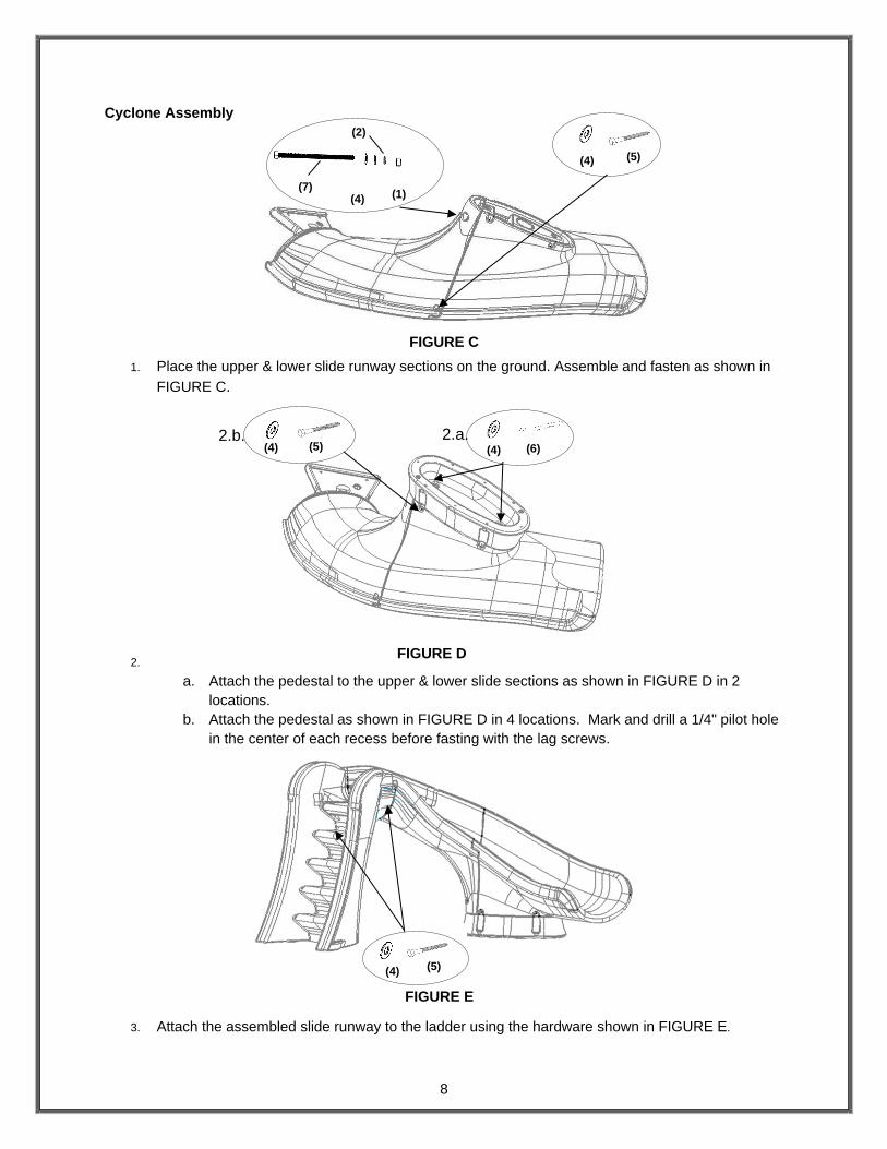
Cyclone Assembly
1. Place the upper & lower slide runway sections on the ground. Assemble and fasten as shown in
FIGURE C.
2.
a. Attach the pedestal to the upper & lower slide sections as shown in FIGURE D in 2
locations.
b. Attach the pedestal as shown in FIGURE D in 4 locations. Mark and drill a 1/4" pilot hole
in the center of each recess before fasting with the lag screws.
3. Attach the assembled slide runway to the ladder using the hardware shown in FIGURE E.
(5) (4)
(5) (4) (6) 2.a. 2.b.
(7) (4) (1)
(2)
(4) (5)
(4)
FIGURE D
FIGURE E
FIGURE C
9
ON-DECK MOUNTING INSTRUCTIONS
1. Place the assembled slide on the deck relative to the pool wall. Ensure that the exit flume clears any coping. Slide may be angled slightly providing all dimensions are maintained as noted in the Manufacturer’s Placement Instructions noted in the following section.
2. With the slide in its proper location, center punch or otherwise mark through the (7) mounting holes at the bottom of the ladder and base so that a visible mark is apparent on the concrete.
3. Move the assembled slide aside to facilitate drilling of the anchoring holes.
4. Using a power drill and a 1/2” concrete drill bit, drill the holes to a depth of 4”. Use tape or a marking on the drill bit to ensure that the hole for the anchor is drilled to the required depth. Maintain drill hole straight and perpendicular for proper holding strength of anchor stud.
5. Clear the holes of all debris. Assemble anchor with nut and washer so that the top of the nut is flush with the top of the anchor. Move the slide over the holes and insert the anchors. Drive anchor through the slide mounting holes so that nut and washer are flush with the surface material.
6. Expand anchor by tightening nut 3 to 5 turns. Once anchor is set remove nut and install a lock washer, item # (3), and retighten nut to a torque of 55 ft.-lbs.
10
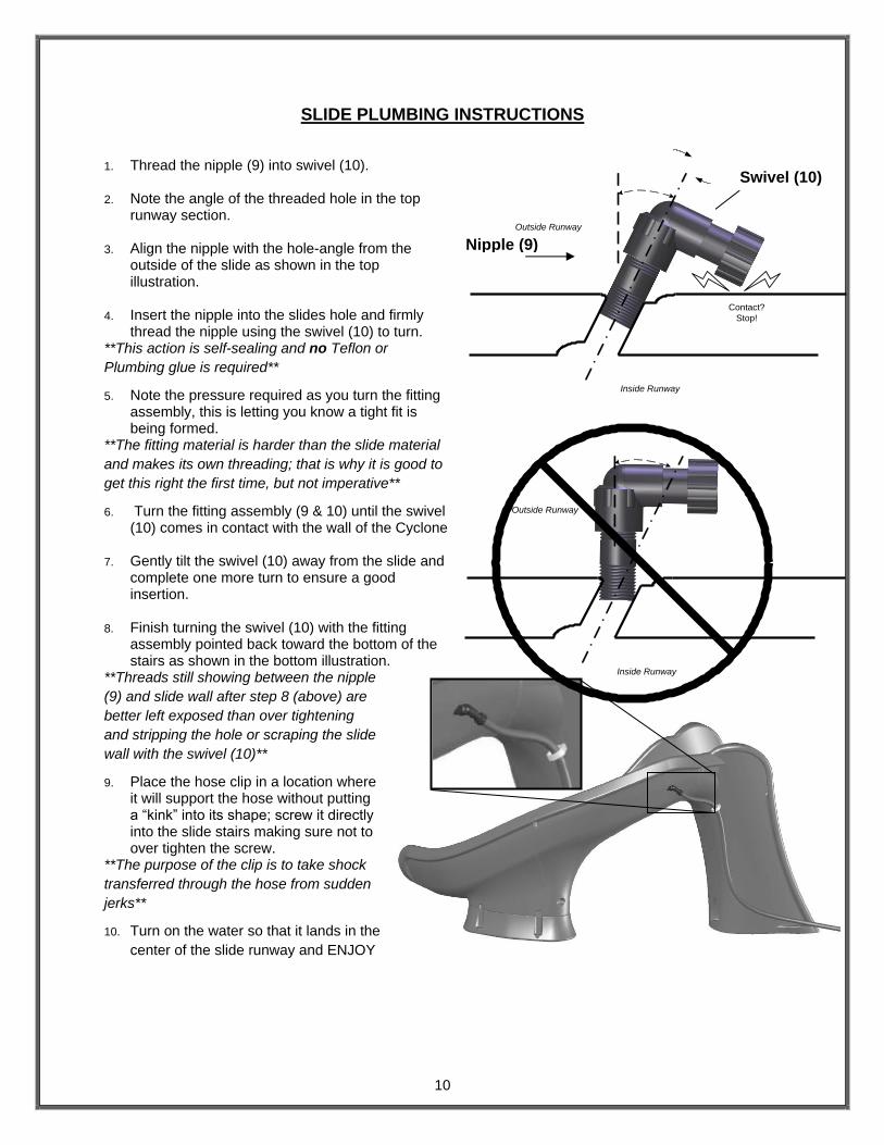
SLIDE PLUMBING INSTRUCTIONS
1. Thread the nipple (9) into swivel (10).
2. Note the angle of the threaded hole in the top runway section.
3. Align the nipple with the hole-angle from the outside of the slide as shown in the top illustration.
4. Insert the nipple into the slides hole and firmly thread the nipple using the swivel (10) to turn.
**This action is self-sealing and no Teflon or
Plumbing glue is required**
5. Note the pressure required as you turn the fitting assembly, this is letting you know a tight fit is being formed.
**The fitting material is harder than the slide material
and makes its own threading; that is why it is good to
get this right the first time, but not imperative**
6. Turn the fitting assembly (9 & 10) until the swivel (10) comes in contact with the wall of the Cyclone
7. Gently tilt the swivel (10) away from the slide and complete one more turn to ensure a good insertion.
8. Finish turning the swivel (10) with the fitting assembly pointed back toward the bottom of the stairs as shown in the bottom illustration.
**Threads still showing between the nipple
(9) and slide wall after step 8 (above) are
better left exposed than over tightening
and stripping the hole or scraping the slide
wall with the swivel (10)**
9. Place the hose clip in a location where it will support the hose without putting a “kink” into its shape; screw it directly into the slide stairs making sure not to over tighten the screw.
**The purpose of the clip is to take shock
transferred through the hose from sudden
jerks**
10. Turn on the water so that it lands in the
center of the slide runway and ENJOY
Nipple (9)
Swivel (10)
Outside Runway
Inside Runway
Outside Runway
Inside Runway
Contact?
Stop!
11
MANUFACTURER’S PLACEMENT INSTRUCTIONS
PROPER ASSEMBLY, INSTALLATION, USE, AND SUPERVISION ARE ESSENTIAL FOR PROPER
OPERATION AND TO REDUCE THE RISK OF SERIOUS INJURY.
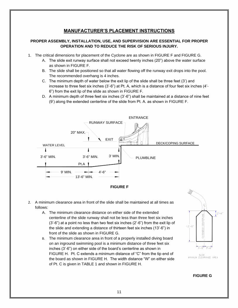
1. The critical dimensions for placement of the Cyclone are as shown in FIGURE F and FIGURE G.
A. The slide exit runway surface shall not exceed twenty inches (20”) above the water surface
as shown in FIGURE F.
B. The slide shall be positioned so that all water flowing off the runway exit drops into the pool.
The recommended overhang is 4 inches.
C. The minimum depth of water below the exit lip of the slide shall be three feet (3’) and
increase to three feet six inches (3’-6”) at Pt. A, which is a distance of four feet six inches (4’-
6”) from the exit lip of the slide as shown in FIGURE F.
D. A minimum depth of three feet six inches (3’-6”) shall be maintained at a distance of nine feet
(9’) along the extended centerline of the slide from Pt. A. as shown in FIGURE F.
2. A minimum clearance area in front of the slide shall be maintained at all times as
follows:
A. The minimum clearance distance on either side of the extended
centerline of the slide runway shall not be less than three feet six inches
(3’-6”) at a point no less than two feet six inches (2’-6”) from the exit lip of
the slide and extending a distance of thirteen feet six inches (13’-6”) in
front of the slide as shown in FIGURE G.
B. The minimum clearance area in front of a properly installed diving board
on an inground swimming pool is a minimum distance of three feet six
inches (3’-6”) on either side of the board’s centerline as shown in
FIGURE H. Pt. C extends a minimum distance of “C” from the tip end of
the board as shown in FIGURE H. The width distance “W” on either side
of Pt. C is given in TABLE 1 and shown in FIGURE H.
FIGURE F
FIGURE G
DECK/COPING SURFACE
3' MIN.
EXIT
RUNWAY SURFACE
PLUMBLINE
20" MAX.
WATER LEVEL
ENTRANCE
Pt.A
13'-6" MIN.
9' MIN. 4'-6"
3'-6" MIN.3'-6" MIN.
12
C. The minimum clearance area of a slide of diving board shall not intersect any coping or rope
and float line as shown in FIGURE I. The minimum clearance area of a slide or diving board
may intersect each other provided that they are not used simultaneously.
See Article 5 contained in ANSI/APSP/ICC-5 2011 STANDARD FOR RESIDENTIAL INGROUND SWIMMING POOLS and refer to FIGURE 3 and Table 1 for Minimum Water Envelope Dimensions AB, BC and Width at Point C.
TABLE 1
Board Minimum Clearance Area
Pool Type “C” Dimension “W” Dimension
I 14’ -6” (4.420 M) 5’ -0” (1.524 M)
II 14’ -6” (4.420 M) 6’ -0” (1.829 M)
III 16’ -6” (5.029 M) 6’ -0” (1.829 M)
IV 18’ -6” (5.639 M) 7’ -6” (2.286 M)
V 21’ -0” (6.401 M) 7’ -6” (2.286 M)
FIGURE H “C” DIMENSION FOR BOARD = AB + BC “W” DIMENSION FOR BOARD = WIDTH AT PT.C