98
CLECO DC ELECTRIC ASSEMBLY TOOLS www.clecotools.com SP-1020EN 7.5M 0212 DC Electric Assembly Tools

SP-1020EN 7.5M 0212SPEcificatioNS SubjEct to chaNgE without NoticE. coPYRight © 2012 aPEX tooL gRouP, LLc. PRiNtED iN uSa.
Apex Tool Group, LLC1000 Lufkin Roadapex, Nc 27539Phone: 919-387-0099fax: 919-387-2614www.clecotools.com
CLE
CO
DC
ELE
CT
RIC
AS
SE
MB
LY T
OO
LS
ww
w.clecoto
ols.co
mS
P-1020E
N 7.5M
0212
Power Tools Sales & Service CentersPlease note that all locations may not service all products. Please contact the nearest apex tool group Sales & Service center for the appropriate facility to handle your service requirements.
D E T R O I T , M I C h I G A n
Apex Tool GroupSales & Service Center2630 Superior courtauburn hills, Mi 48326tel: (248) 393 5640fax: (248) 391 6295
h O u S T O n , T E x A S
Apex Tool GroupSales & Service Center6550 west Sam houston Parkway North, Suite 200houston, tX 77041tel: (713) 849 2364fax: (713) 849 2047
S E A T T L E , W A S h I n G T O n
Apex Tool GroupSales & Service Center2865 152nd ave N.E. Redmond, wa 98052tel: (425) 497 0476fax: (425) 497 0496 L E x I n G T O n , S C
Apex Tool Group670 industrial DriveLexington, Sc 29072tel: (800) 845 5629tel: (803) 951 7544fax: (803) 358 7681
L O S A n G E L E S , C A L I f O R n I A
Apex Tool GroupSales & Service Center6881 Stanton avenue, unit b buena Park, ca 90621tel: (714) 994-1491fax: (714) 994-9576
Y O R k , P E n n S Y L v A n I A
Apex Tool GroupSales & Service CenterYork Service center 3990 E. Market Street York, Pa 17402tel: (717) 755 2933fax: (717) 757 5063
B R A z I L
Cooper Tools Industrial Ltda. an apex tool group, LLc companyav. Liberdade, 4055Zona industrial - iporanga18087-170 SorocabaSP braziltel: +55 15 2383929fax: +55 15 2383260
C A n A D A
Apex Tool GroupSales & Service Center5925 McLaughlin RoadMississauga, ont. L5R 1b8 canadatel: (905) 501 4785fax: (905) 501 4786
C h I n A
Cooper (China) Co., Ltd.an apex tool group, LLc company955 Sheng Li Road,heqing Pudong, Shanghaichina 201201tel: +86 21 28994176fax: +86 21 51118446
E n G L A n D
Apex Tool Group GmbH & Co. OHGc/o Spline gaugesPiccadilly, tamworth,Staffordshire b78 2ER united Kingdomtel: +44 1827 8741 28fax: +44 1827 8741 28
f R A n C E
Apex Tool Group SAS 25 rue Maurice chevalierb. P. 2877831 ozoir-la-ferrière cedexfrancetel: +33 1 64 43 22 00 fax: +33 1 64 43 17 17
G E R M A n Y
Apex Tool Group GmbH & Co. OHGindustriestraße 173463 westhausengermanytel: +49 (0) 73 63 81 0fax: +49 (0) 73 63 81 222
h u n G A R Y
Cooper Tools Hungaria Kft.an apex tool group, LLc companyberkenyefa sor 7Pf: 640 9027 györhungarytel: +36 96 66 1383fax: +36 96 66 1135
M E x I C O
Cooper Tools de México S.A. de C.V.an apex tool group, LLc companyVialidad El Pueblito #103 Parque industrial QuerétaroQuerétaro, QRo 76220Mexicotel: +52 (442) 211 3800fax: +52 (442) 103 0443
www.apextoolgroup.com
www.apextoolgroup.eu
DC Electric Assembly Tools

1
Table of Contents
DC Electric Tools Introduction . . . . . . . . . . . . . . . . . . . . . . . . . . . . 2-3
How To Build A DC Global Controller System . . . . . . . . . . . . . . . 4-5
Cordless Transducer Control Tools . . . . 6 Right Angle Tools . . . . . . . . . . . . . . . . . . . . . . . . . . . . . . . . . . . 10 Pistol Tools . . . . . . . . . . . . . . . . . . . . . . . . . . . . . . . . . . . . . . . . 11 Tube Nut Tools . . . . . . . . . . . . . . . . . . . . . . . . . . . . . . . . . . . . . 12 Crowfoot Tools . . . . . . . . . . . . . . . . . . . . . . . . . . . . . . . . . . . . . 13 Cordless Tool Batteries & Chargers . . . . . . . . . . . . . . . . . . . . . 14 LiveWire Power Module . . . . . . . . . . . . . . . . . . . . . . . . . . . . . . 15 mPro400GC Controllers . . . . . . . . . . . . . . . . . . . . . . . . . . . . . . 15
Corded Transducer Control Tools . . . . . . 16 Right Angle Tools . . . . . . . . . . . . . . . . . . . . . . . . . . . . . . . . . . . . 18 Inline Tools . . . . . . . . . . . . . . . . . . . . . . . . . . . . . . . . . . . . . . . . . 20 Pistol Tools . . . . . . . . . . . . . . . . . . . . . . . . . . . . . . . . . . . . . . . . . 22 Push-to-Start Tools . . . . . . . . . . . . . . . . . . . . . . . . . . . . . . . . . . 23 Inline Floating Spindle Tools . . . . . . . . . . . . . . . . . . . . . . . . . . . 24 Hold & Drive Tools . . . . . . . . . . . . . . . . . . . . . . . . . . . . . . . . . . . 26 Flush Socket Tools . . . . . . . . . . . . . . . . . . . . . . . . . . . . . . . . . . . 27 Tube Nut Tools . . . . . . . . . . . . . . . . . . . . . . . . . . . . . . . . . . . . . . 28 Crowfoot Tools . . . . . . . . . . . . . . . . . . . . . . . . . . . . . . . . . . . . . . 29 Right Angle Floating Spindle Tools . . . . . . . . . . . . . . . . . . . . . . 30 How To Build A DC Global Controller System . . . . . . . . . . . . 38 mPro400GC Controllers . . . . . . . . . . . . . . . . . . . . . . . . . . . . . . 40
Corded Current Control Tools . . . . . . . . . 42 Right Angle Tools . . . . . . . . . . . . . . . . . . . . . . . . . . . . . . . . . . . . 44 Inline Tools . . . . . . . . . . . . . . . . . . . . . . . . . . . . . . . . . . . . . . . . . 45 Pistol Tools . . . . . . . . . . . . . . . . . . . . . . . . . . . . . . . . . . . . . . . . 46 Push-to-Start Tools . . . . . . . . . . . . . . . . . . . . . . . . . . . . . . . . . . 47 Inline Floating Spindle Tools . . . . . . . . . . . . . . . . . . . . . . . . . . . 48 Hold & Drive Tools . . . . . . . . . . . . . . . . . . . . . . . . . . . . . . . . . . . 49 Flush Socket Tools . . . . . . . . . . . . . . . . . . . . . . . . . . . . . . . . . . 50 Tube Nut Tools . . . . . . . . . . . . . . . . . . . . . . . . . . . . . . . . . . . . . 51 Right Angle Floating Spindle Tools . . . . . . . . . . . . . . . . . . . . . 52 Crowfoot Tools . . . . . . . . . . . . . . . . . . . . . . . . . . . . . . . . . . . . . 54 mPro400GC-I Controller . . . . . . . . . . . . . . . . . . . . . . . . . . . . . . 55 Isolation Transformer . . . . . . . . . . . . . . . . . . . . . . . . . . . . . . . . . 56
Remote Programming Software . . . . . . . . . . . . . . . . . . . . . . . . 57
Accessories . . . . . . . . . . . . . . . . . . . . . 58 Cordless Tool Accessories . . . . . . . . . . . . . . . . . . . . . . . . . . . . 58 Corded Tool Accessories . . . . . . . . . . . . . . . . . . . . . . . . . . . . . 59
Balance Arms & Balancers . . . . . . . . . . . . . . . . . . . . . . . . . . . . 63
Automated Systems . . . . . . . . . . . . . . 65 Introduction . . . . . . . . . . . . . . . . . . . . . . . . . . . . . . . . . . . . . . . . 65 Articulating Arms & Cable Management . . . . . . . . . . . . . . . . . 67 Torque Handling System . . . . . . . . . . . . . . . . . . . . . . . . . . . . . . 68 Wheelnut Fastening . . . . . . . . . . . . . . . . . . . . . . . . . . . . . . . . . . 69 Intelligent Spindles . . . . . . . . . . . . . . . . . . . . . . . . . . . . . . . . . . . 72 How To Build A Fixtured DC Global Controller System . . . . . 74 Intelligent Spindle Accessories . . . . . . . . . . . . . . . . . . . . . . . . . 76 Conventonal Fixtured Spindles . . . . . . . . . . . . . . . . . . . . . . . . 81
General Accessories & Information . . 86 Apex Bits & Sockets . . . . . . . . . . . . . . . . . . . . . . . . . . . . . . . . . 86 Conversion Charts . . . . . . . . . . . . . . . . . . . . . . . . . . . . . . . . . . 90 Model Number Index . . . . . . . . . . . . . . . . . . . . . . . . . . . . . . . . 94 Waranty & Lubrication . . . . . . . . . . . . . . . . . . . . . . . . . . . . . . . . 96
Safety Critical
Quality Critical
Accessories
Fixtured Safety Critical

Cleco's fastening technology is used globally and across all industries. This technology is used in Aerospace, Motor Vehicle, Offroad, Wind Energy, Agriculture, and a great multitude of applications within general industry where “quality critical” requirements are the rule. In motor vehicle environments across the globe, Cleco and DGD's complete line of transducerized electric tools are used in “safety critical” applications where spot-on precision and traceability are required. And finally, in one of the most demanding environments, our line of DC electric tools are used in aircraft assembly where “good enough” will never be acceptable.
Because of our drive for perfection, you can excel in your job. Indeed, due to our uncommon focus on
total fastening solutions instead of just products, our customers look upon us not merely as vendors, but as strategic allies. And at Apex, we welcome the challenge of leadership this imposes.
The Systems
Cleco's state of the art Tightening System delivers unprecedented performance, productivity and accountability in both “quality critical” and “safety critical” assembly applications.
Durability, speed, and ergonomics are achieved using the corded Cleco DC electric tools with a complete line of tool configurations and an assortment of controller options to choose from.
2
The Total Solution For Quality & Critical Fastening Operations

The Cleco LiveWire™ system provides the most cost-effective safety critical fastening solution available in the world today. By marrying cordless tools and WiFi communications, the operators gain the mobility and flexibility they need to increase productivity and reduce in-system damage costs. One line controller managing up to 10 cordless tools while utilizing the most up-to-date wireless encryption technology provides a cost savings unparalleled in industry today. When considering the cumulative impact of all these components – the tools, the controllers, the software, the flexibility, the accessories and the support – it is easy to see why the Cleco Tightening System is the benchmark for all DC electric tool systems.
3

4
How To Build A DC Global Controller SystemmPro400GC-M, mPro400GC-P & mPro400GC-S
Building a DC Global Controller System is as simple as 1, 2, 3!
1. Choose a common system to the right. 2. Select the correct components below. 3. Order your System!
Controller (Page 40)
mPro400GC-M (Master) 1 1
mPro400GC-P (Primary) 1 1 1 1 1 1
mPro400GC-S (Secondary) 1 2
Corded Tool (Page 18-30)18/48E_EXXX 1 1 2 1 3
67E_XXX 1
Cable (Page 60)
Tool Cable - 301866-XM (Air-Lb) 1 1 2 1 3Tool Cable - 542778-XM (Matrix) 1Extension Cable - 301877-XM (If Required) (Air-Lb)Extension Cable - 542779-XM (If Required) (Matrix)
LiveWire Tool (Pages 10-13) 17/47B___BXX 1 1 3
Access Point (Page 58)543995 (US)961323 (EU)
1 1 1
IRDA Device (Infrared Cable) (Page 58)
935170 IRDA Only935144 Pistol Holder w/IRDA935290 Right Angle Holder w/IRDA935999 70Nm, 90Nm, Crowfoot/Tubenut Holder w/IRDA
1 1 1
System Bus Cable (Page 59)
544196-005 (0.5M)544196-020 (2M)544196-050 (5M)544196-200 (20M)544196-500 (50M)
1 1 1 2 3
System Bus Terminator Plug (Page 59) 544197PT 1 1 1 1 1
System Bus Accessories (Page 59)
S133420 Stack Light 3S133410 4-Position Socket Tray 1S133411 8-Position Socket Tray 1S133406 Control Box 1
Isolation Transformer (Page 56) 544185PT 1
(Refer to Pages 38-39 to build a mPro400GC-E/GC-I system.)

5
Controller (Page 40)
mPro400GC-M (Master) 1 1
mPro400GC-P (Primary) 1 1 1 1 1 1
mPro400GC-S (Secondary) 1 2
Corded Tool (Page 18-30)18/48E_EXXX 1 1 2 1 3
67E_XXX 1
Cable (Page 60)
Tool Cable - 301866-XM (Air-Lb) 1 1 2 1 3Tool Cable - 542778-XM (Matrix) 1Extension Cable - 301877-XM (If Required) (Air-Lb)Extension Cable - 542779-XM (If Required) (Matrix)
LiveWire Tool (Pages 10-13) 17/47B___BXX 1 1 3
Access Point (Page 58)543995 (US)961323 (EU)
1 1 1
IRDA Device (Infrared Cable) (Page 58)
935170 IRDA Only935144 Pistol Holder w/IRDA935290 Right Angle Holder w/IRDA935999 70Nm, 90Nm, Crowfoot/Tubenut Holder w/IRDA
1 1 1
System Bus Cable (Page 59)
544196-005 (0.5M)544196-020 (2M)544196-050 (5M)544196-200 (20M)544196-500 (50M)
1 1 1 2 3
System Bus Terminator Plug (Page 59) 544197PT 1 1 1 1 1
System Bus Accessories (Page 59)
S133420 Stack Light 3S133410 4-Position Socket Tray 1S133411 8-Position Socket Tray 1S133406 Control Box 1
Isolation Transformer (Page 56) 544185PT 1
One Corded Tool (18/48E_E)
One Corded Tool (67E_XXX) with a Control Box
One Corded Tool (18/48E_E) w/LiveWire™
Two Corded Tools (18/48E_E) with 8-Pos Socket Tray
One Corded 18/48E_E Tool w/4-Position Socket Tray
Three Corded Tools (18/48E_E)
One LiveWire™
Tool only
Three LiveWire™
Tools Only w/3 Stack LightsModel/Part Number
Add or delete components as required.

6
Electric Nutrunners – Cordless Transducer ControlLiveWire® Wireless Communications
LiveWire™ offers precision torque, angle and speed control features for safety critical fastening in an ergonomic, wireless design.
With up to 1,700 rundowns per battery charge or continuous power, your safety critical applications are assured to never run out of power.
LiveWire™ has been designed and tested to provide wireless connectivity across the harshest of machine-to-machine environments.
All The Brains. All The Power. And It’s Wireless.
Electronic Intelligence■ On-board controller with power management
■ Integrated servo with I/O signal handling
■ Auto sensing power intelligence
■ 512 cycle memory buffer
Digital Process Control■ Auto bolt sequencing
■ Auto image selection
■ Configurable reject management

7
Modular Tightening System
CustomerDataServer
Line ControlSystem
RemoteProgramming/Monitoring
Plant/LocalAccess Point
Cordless Handheld Tools
Up To 10 Tools/Controller
One controller manages up to 32 tools simultaneously in varying combinations.
Fiel
dbus
/ I/
O
Eth
erne
t TC
P/I
P
Fixtured Intelligent Spindles
Corded Handheld Tool
WirelessTorque Wrench
Configurable LED Illumination
All The Brains. All The Power. And It’s Wireless.Integrated Bar Code Scanner (optional)
■ Enables real-time bar code data collection
■ Programmable bit for Auto Parameter Select
■ Tool enable and disable configurability
Operator Display■ Real-time interface
■ Redundant feedback •GreenLCD=OK •YellowLCD=Running •RedLCD=NOK/Errors •GreenLED=OK •RedLED=NOK
■ Configurable application buttons

8
The Most Cost-Effective Safety Critical Solution Available. Up To 50% Savings Over Traditional Systems!Mobility is a major advantage with wireless communications. Cleco LiveWire™ marries the freedom and flexibility of cordless tools with real-time wireless error proofing. Utilizing an industrystandard2.4/5GHzWLAN(WirelessLocalAreaNetwork)interfaceinconjunctionwith the highest security encryption and authentification levels, plus a 512-cycle tool memory buffer, LiveWire™ ensures you will never compromise safety critical data transmissions.
10 LiveWire Tools.1 Line
Controller.
Electric Nutrunners – Cordless Transducer ControlLiveWire® Wireless Communications
8
2.4 or
5GHz
WLAN

9
The Most Cost-Effective Safety Critical Solution Available.
Wireless Security■ WEP (Wired Equivalent Privacy)•64/128BitEncryptionHEX(RC4)
■WPA(WirelessProtectedAccess)/WPA2/802.11•128BitTKIP/CCMPEncryption•802.1xEAP Authentification - LEAP, PEAP, TTLS - GTC, MD5, OTP, PAP, CHAP, MSCHAP, MSCHAPv2, TTLS MSCHAPv2
Up To 83% More Productivity!Cleco LiveWire™ tools are now available with Vmax™, a solution that drives tool power and speed increasesupto83%withoutlosingaccuracyordurability.Thisleadinginnovationutilizesthesame10toolstoonelinecontrollerhardwaresolutionwithupto50%costsavingsovertraditionalsystems.NewVmax™ technology auto-senses the applied power source and adjusts the maximum tool speed capability on the fly. LiveWire™ with Vmax™ combines the power you need with the most versatile wireless system available today.
9
10
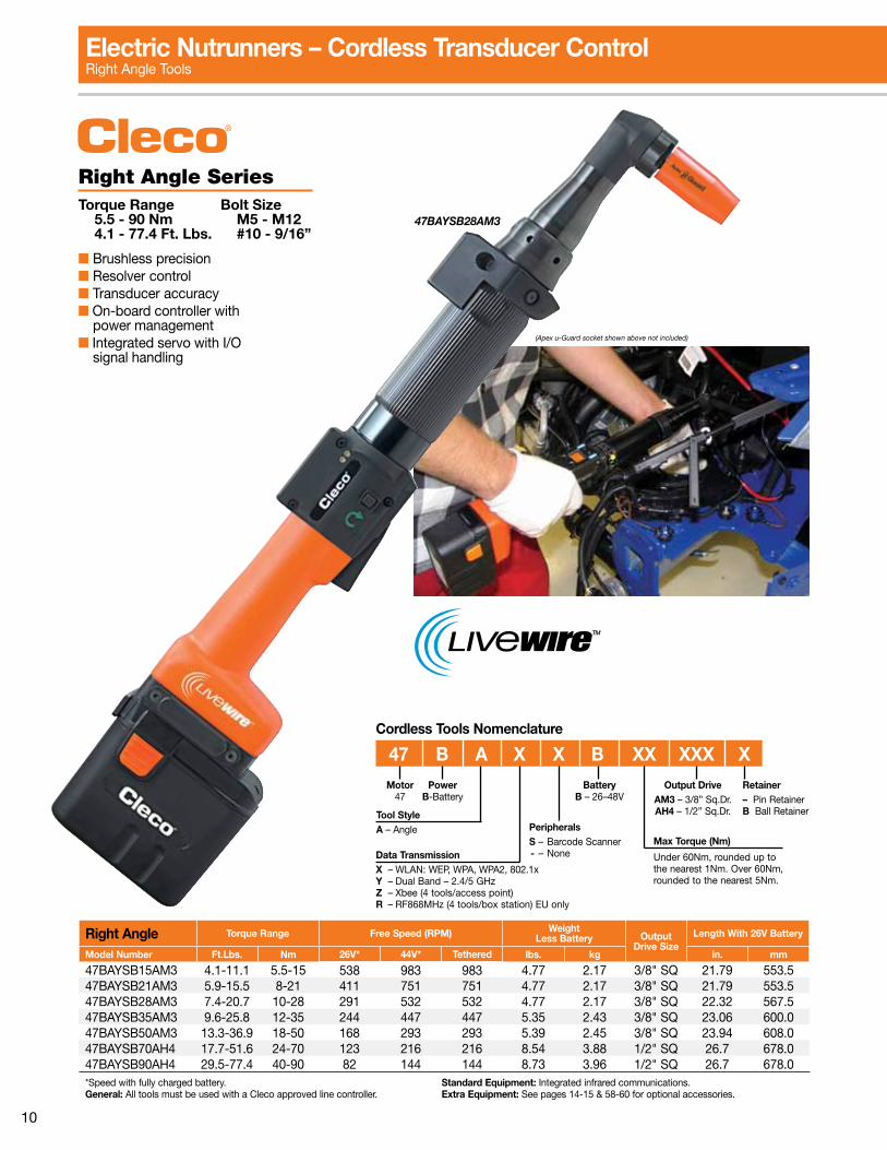
Electric Nutrunners – Cordless Transducer ControlRight Angle Tools
Data TransmissionX – WLAN: WEP, WPA, WPA2, 802 .1xY – Dual Band – 2 .4/5 GHzZ – Xbee (4 tools/access point)R – RF868MHz (4 tools/box station) EU only
PeripheralsS – Barcode Scanner - – None
Motor47
Tool StyleA – Angle
PowerB-Battery
47 B A X X B XX XXX X
Max Torque (Nm)
Under 60Nm, rounded up to the nearest 1Nm . Over 60Nm, rounded to the nearest 5Nm .
BatteryB – 26–48V
Output DriveAM3 – 3/8” Sq .Dr .AH4 – 1/2” Sq .Dr .
Retainer– Pin RetainerB Ball Retainer
Cordless Tools Nomenclature
Right Angle SeriesTorque Range Bolt Size 5.5 - 90 Nm M5 - M12 4.1 - 77.4 Ft. Lbs. #10 - 9/16”
■ Brushless precision■ Resolver control■ Transducer accuracy■ On-board controller with power management■ Integrated servo with I/O signal handling
47BAYSB28AM3
Right Angle Torque Range Free Speed (RPM) WeightLess Battery Output
Drive SizeLength With 26V Battery
Model Number Ft.Lbs. Nm 26V* 44V* Tethered lbs. kg in. mm
47BAYSB15AM3 4 .1-11 .1 5 .5-15 538 983 983 4 .77 2 .17 3/8" SQ 21 .79 553 .547BAYSB21AM3 5 .9-15 .5 8-21 411 751 751 4 .77 2 .17 3/8" SQ 21 .79 553 .547BAYSB28AM3 7 .4-20 .7 10-28 291 532 532 4 .77 2 .17 3/8" SQ 22 .32 567 .547BAYSB35AM3 9 .6-25 .8 12-35 244 447 447 5 .35 2 .43 3/8" SQ 23 .06 600 .047BAYSB50AM3 13 .3-36 .9 18-50 168 293 293 5 .39 2 .45 3/8" SQ 23 .94 608 .047BAYSB70AH4 17 .7-51 .6 24-70 123 216 216 8 .54 3 .88 1/2" SQ 26 .7 678 .047BAYSB90AH4 29 .5-77 .4 40-90 82 144 144 8 .73 3 .96 1/2" SQ 26 .7 678 .0*Speed with fully charged battery . General: All tools must be used with a Cleco approved line controller .
Standard Equipment: Integrated infrared communications .Extra Equipment: See pages 14-15 & 58-60 for optional accessories .
(Apex u-Guard socket shown above not included)

11
Electric Nutrunners – Cordless Transducer ControlPistol Grip Tools
17BPYSB13Q
Data TransmissionX – WLAN: WEP, WPA, WPA2, 802 .1xY – Dual Band – 2 .4/5 GHz Z – Xbee (4 tools/access point)R – RF868MHz (4 tools/box station) EU only
PeripheralsS – Barcode Scanner - – None
Motor17
Tool StyleP – Pistol
PowerB-Battery
17 B P X X B XX Q
Max Torque (Nm)
Under 60Nm, rounded up to the nearest 1Nm .
BatteryB – 26–48V
Output DriveQ – Quick change
Cordless Tools Nomenclature
Pistol Grip SeriesTorque Range Bolt Size 3.0 - 13 Nm M5 - M6 2.2 - 9.6 Ft. Lbs. #10 - 1/4”
■ Brushless precision■ Resolver control■ Transducer accuracy■ On-board controller with power management■ Integrated servo with I/O signal handling
Pistol Torque Range Free Speed (RPM) WeightLess Battery Output
Drive SizeLength With 26V Battery
Model Number Ft.Lbs. Nm 26V* 44V* Tethered lbs. kg in. mm
17BPYSB05Q 2 .2-3 .7 3-5 1639 2428 2428 3 .34 1 .52 1/4" Hex 8 .44 214 .517BPYSB07Q 2 .2-5 .2 3-7 1161 1721 1721 3 .34 1 .52 1/4" Hex 8 .44 214 .517BPYSB09Q 2 .2-6 .6 3-9 887 1314 1314 3 .34 1 .52 1/4" Hex 8 .44 214 .517BPYSB13Q 2 .2-9 .6 3-13 629 931 931 3 .34 1 .52 1/4" Hex 8 .44 214 .5*Speed with fully charged battery . General: All tools must be used with a approved Cleco line controller .
Standard Equipment: Integrated infrared communications .Extra Equipment: See pages 14-15 & 58-60 for optional accessories .
(Apex u-Guard socket shown above not included)

12
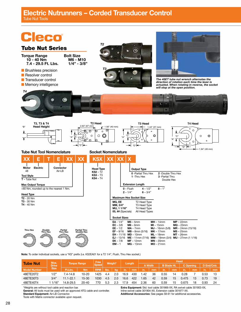
Electric Nutrunners – Cordless Transducer ControlTube Nut Tools
“B”T2, T3 & T4Head Height
“A”
2.63” (67 mm) 1.56” (40 mm)T2 Head T3 Head
1.44” (37 mm)
“A”“C”
“D”
T4 Head
1.94” (49 mm)
“A”“C”
“D”
“C”
“D”
T3
T4
Tube Nut SeriesTorque Range Bolt Size 10 - 40 Nm M6 - M8 7.4 - 29.5 Ft. Lbs. 1/4” - 7/16”
■ Brushless precision■ Resolver control■ Transducer accuracy■ On-board controller with power management■ Integrated servo with I/O signal handling
47BTYSB20T2
The 47BT tube nut wrench alternates the direction of rotation each time the lever is actuated. When rotating in reverse, the socket will stop at the open position.
Tube Nut Torque Range FreeSpeed (RPM)
WeightLess Battery
Max.Drive Size
Length w/26V Battery
HeadA Width B Blade Ht. C Opening D End/Cntr.
Model Number Ft.Lbs. Nm 26V* 44V* 48V lbs. kg in. mm in. mm in. mm in. mm in. mm
47BTYSB20T2 7 .4-14 .8 10-20 260 455 455 5 .6 2 .54 1/2" 23 .6 598 1 .42 36 0 .55 14 0 .28 7 0 .53 1347BTYSB30T3 11 .1-22 .1 15-30 188 329 329 5 .6 2 .53 3/4" 23 .3 588 1 .65 42 0 .59 15 0 .475 12 0 .73 1947BTYSB40T4 14 .8-29 .5 20-40 141 247 247 6 .4 2 .90 1 1/16" 29 .9 612 2 .36 60 0 .59 15 0 .675 17 0 .93 24*Speed with fully charged battery . General: All tools must be used with a Cleco approved line controller .
Standard Equipment: Integrated infrared communications . Extra Equipment: See pages 14-15 & 58-60 for optional accessories .
To order individual sockets, use a “KS” prefix . (i .e . KS2EA01 for a T2, 1/4”, flush, thru hex socket .)
Tube Nut Tool Nomenclature Socket Nomenclature
PeripheralsS – Barcode Scanner - – None
BatteryB-26V-48V
Series47
Tool StyleT – Tube Nut
PowerB–Battery
Output Type
0 -Partial Thru Hex 2 -Double Thru Hex1 -Thru Hex 3 -Partial Thru Double Hex
Extension Length
0 – Flush 4 – 1/2”2 – 1/4” 6 – 3/4”
Maximum Hex Socket Size
MG, EE T2 Head TypeMM T3 Head TypeMU T4 Head Type00, ## (Specials) All Head Types
Socket Sizes
EA - 1/4” M5 – 5mm MH – 14mm MP – 22mmEC – 3/8 M6 – 6mm MI – 15mm MQ – 23mmEE – 1/2 MA – 7mm MJ – 16mm (5/8”) MR – 24mm (15/16”)EF – 9/16 MB – 8mm (5/16) MK – 17mm MS – 25mmEH – 11/16 MD – 10mm ML – 18mm MT – 26mmEJ – 13/16 ME – 11mm (7/16) MM – 19mm (3/4”) MU – 27mm (1 1/16”)EK – 7/8 MF – 12mm MN – 20mmEM – 1 MG – 13mm MO – 21mm
47 B T X X X XX XX KSX XX XX X
Data TransmissionX – WLAN: WEP, WPA, WPA2, 802 .1xY – Dual Band – 2 .4/5 GHz Z – Xbee (4 tools/access point)R – RF868MHz (4 tools/box station) EU only
Head TypeT2 - 20 NmT3 - 30 NmT4 - 40 Nm
Thru Hex DoubleThru Hex
PartialThru Hex
Partial Thru Double Hex
Head TypeKS2 – T2KS3 – T3KS4 – T4
Max Torque (Nm)
Under 60Nm, rounded up to the nearest 1Nm . Over 60Nm, rounded to the nearest 5Nm .

13
Electric Nutrunners – Cordless Transducer ControlCrowfoot Tools
.61”(15.49)
.97”(24.63)
.75”(19)
3.00”(76.2)
30°
R.63”(16)
1.25”(31.75)
1.50”(38.1)
.25”(6.35)
C3 – 30° Head (Part No. 301960)Maximum Recommended Torque: 22 ft .lbs . (30 Nm)
15°
.61”(15.49)
1.09”(27.86)
.75”(19)
3.00”(76.2)
2.66”(67.56)
1.50”(38.1)
1.25”(31.75)
R.63”(16)
.25”(6.35)
C1 – 15° Head (Part No. 301959)Maximum Recommended Torque: 22 ft .lbs . (30 Nm)
Crowfoot SeriesTorque Range Bolt Size 10.5 - 30 Nm M6 - M8 7.7 - 22.1 Ft. Lbs. 1/4” - 7/16”
■ Brushless precision■ Resolver control■ Transducer accuracy■ On-board controller with power management■ Integrated servo with I/O signal handling
47BCYSB30C1
Crowfoot Torque Range Free Speed(RPM) Weight Less Battery Max.
DriveSize
Length w/26V Battery
Model Number ft. lbs. Nm 26V* 44V* 48V lbs. kg in. mm
47BCYSB30C1 7 .7-22 .1 10 .5-30 186 326 326 6 .12 2 .78 1/2” 26 .26 667
47BCYSB30C3 7 .7-22 .1 10 .5-30 186 326 326 6 .12 2 .78 3/4” 25 .98 660
*Speed with fully charged battery . General: All tools must be used with a Cleco approved line controller .
Standard Equipment: Integrated infrared communications .Extra Equipment: See pages 14-15 & 58-60 for optional accessories .
To order individual sockets, use a “CS” prefix before the required socket . (i .e . CSEE01 for a 1/2”, flush, thru hex socket .)
Socket TypeCS – Crowfoot
Data TransmissionX – WLAN: WEP, WPA, WPA2, 802 .1xY – Dual Band – 2 .4/5 GHz Z – Xbee (4 tools/access point)R – RF868MHz (4 tools/box station) EU only
Peripherals– - NoneS - Barcode scanner
Series47
Tool StyleC – Crowfoot
Battery Output Type
1 – Thru Hex
Extension Length
0 – Flush 4 – 1/2” 6 – 3/4”
Socket Size
EA - 1/4” MA – 7mm MF – 12mmEC – 3/8 MB – 8mm (5/16) MG – 13mmEE – 1/2 MC – 9mm MH – 14mmEF – 9/16 MD – 10mm MI – 15mm* ME – 11mm (7/16) *Fragile. Light duty apps.
Socket NomenclatureCrowfoot Tool Nomenclature
47 B C X X B XX XX CS XX X X
Head TypeC1 - 15°C3 - 30°
BatteryB – 26V-48V
Max Torque (Nm)
Under 60Nm, rounded up to the nearest 1Nm . Over 60Nm, rounded to the nearest 5Nm .

14
Cordless Tool Accessories Batteries & Chargers
CordlessFreedom
or
TetheredSpeed . . .
The Choice Is Yours .
Charger Display For Advanced FeedbackPower Supply
LED Display Status
No Main SupplyMain Supply OK
Red/Green LED For Charge & ErrorLED Display Status
No Battery Flash @ .5 Hz Charging, Level > 80% Flash @ 1 Hz Charging, Level < 80%
Battery 100% Charge Cell Over Temperature Flash @ 2 Hz Battery Error
(Short circuit, defective cell, etc .)
26V/44V Charger Technology■ Auto-sensing 26/44V■ One hour charge cycle■ Auto-sensing input (85-270) VAC■ Power/Status LEDs
936491PT
The cells and electronic balancing circuit are fixed to an internal cell holder to provide maximum durability.
44V Li-Ion Battery Technology■ Up to 83% faster vs . 26V battery■ Up to 1,700 rundowns/charge (hard joint)■ Life > 800 charging cycles■ On-board intelligence •Chargelevel/cyclesLCD •DiagnosticstoaPC■ Single tab, one-hand removal
5 bar on-battery display for advanced feedback
Single tab removal
936400PT
Charge Level – Operational display
Display Charge Level
Deep Sleep Mode or Defective< 20%20 – 40%40 – 60%60 – 80%80 – 100%
Charge Cycles – Unplugged display
Display Charge Cycles
0 – 199200 – 399400 – 599600 – 799> 800

15
Cordless Tool Accessories Power Modules, Controllers & Software
Low-Cost Software Solution ■ No error proofing ■ No software licensing ■ Up to 10 tools to PC ■ Local data storage
TMEB-COM-V2.03
=
Series Model Number
Free Speed (RPM) %
Increase26V Battery Tethered
Pis
tol
17BPYSB05Q 1639 2428 48%17BPYSB07Q 1161 1721 48%17BPYSB09Q 887 1314 48%17BPYSB13Q 629 931 48%
Rig
ht A
ngle
47BAYSB15AM3 538 983 83%47BAYSB21AM3 411 751 83%47BAYSB28AM3 291 532 83%47BAYSB35AM3 244 447 83%47BAYSB50AM3 168 293 75%47BAYSB70AH4 123 216 75%47BAYSB90AH4 82 144 75%
Speed Improvement Comparison
LiveWire Power Module■ Up to 83% faster!■ Auto sensing input – (85-275 VAC)■ Power & status LEDs■ Electronic circuit protection
mPro400GC Controller■ Up to 16 tools per controller (LiveWire + Corded + Fixtured)■ 10 .4” display with wide viewing angle■ Touchscreen with alpha numeric entry■ Corded and cordless functionality■ Redundant Ethernet and Fieldbus ports■ Serial and USB connectivity■ Configurable 24V I/O■ System bus standard■ Fieldbus optional
mPro400GC Nomenclature
Controller Style Series
MPRO 400GC XType
M – MasterP – Primary
Model Number* DescriptionWeight Width Height Depth*
lbs. kg in. mm in. mm in. mm
MPRO400GC-M Master controller, display, no servo, Fieldbus optional 23 .3 10 .57 10 .5 266 .7 15 381 .0 13 .24 336 .29
MPRO400GC-P Primary controller, display, STMH servo, Fieldbus optional 30 .8 13 .97 10 .5 266 .7 15 381 .0 13 .24 336 .29
*Includes mounting bracket.See additional information on pages 32-40.
Global Controllers

16
Durability. Speed. Ergonomics.Cleco18-48seriestoolsaredrivenbyamaintenance-freebrushlessmotorwithupto50%more speed and productivity. This motor technology coupled with our high-resolution resolver offersfullrangecontrolforsafetycriticaljoints.The18-48seriestoolswithindustryprovengeartrains create outstanding durable production performance.
TheCleco18-48serieselectrictoolsprovideauniquemodularassemblydesignforeaseofrepair. The on-board intelligent memory chip records tool set-up values and counts cycles for maintenance scheduling to prevent costly production downtime.
Highly visible operator feedback LEDs
Intelligent memory
chip
Low compression
switch
Ergonomic handle for operator comfort
Resolver technology for full range speed control
Tools shown with Apex® u-Guard™ protective covered industrial sockets. Cover spins independently of socket virtually eliminating damages and risks associated with incidental contact between the tool and the workpiece or user. Not included with tool.
Error free connector
(in tool handle)
Air-LB(Tools with Matrix connector
available upon request.)
Electric Nutrunners – Corded Transducer Control

17
Durability. Speed. Ergonomics.Optimal tool weight
and balance
Reaction transducer for consistent torque
repeatability
Standard tools required for service
Durable industry proven
gear train
Tools shown with Apex® u-Guard™ protective covered industrial sockets. Cover spins independently of socket virtually eliminating damages and risks associated with incidental contact between the tool and the workpiece or user. Not included with tool.
Adjustable angle head allows flexible orientationLow inertia brushless motor
for superior fastening control

18
Right Angle Torque Range Max.Speed Weight* Output
DriveSize
LengthAnglehead
Side to Center Height
Model Number ft. lbs. Nm RPM lbs. kg in. mm in. mm in. mm
18EAE08AL2 1 .5-5 .9 2-8 3000 2 .9 1 .3 1/4” 13 .6 345 0 .51 13 1 .4 3618EAE15AM3 3 .0-11 .1 4-15 1300 3 .3 1 .5 3/8” 14 .8 376 0 .59 15 1 .6 4118EAE22AM3 3 .7-16 .2 5-22 920 3 .3 1 .5 3/8” 14 .8 376 0 .59 15 1 .6 4118EAE28AM3 4 .4-20 .7 6-28 700 3 .3 1 .5 3/8” 14 .8 376 0 .59 15 1 .6 4148EAE15AL3 2 .2-11 .1 3-15 2855 3 .8 1 .7 3/8” 15 .7 398 0 .59 15 1 .6 4148EAE28AL3 4 .4-20 .7 6-28 1300 4 .1 1 .9 3/8” 16 .2 410 0 .59 15 1 .6 4148EAE41AM3 6 .6-30 .2 9-41 1090 4 .3 2 .0 3/8” 17 .3 440 0 .75 19 1 .9 4848EAE58AM3 8 .9-42 .8 12-58 770 4 .3 2 .0 3/8” 17 .3 440 0 .75 19 1 .9 4848EAE58AM4 8 .9-42 .8 12-58 770 4 .3 2 .0 1/2” 17 .3 440 0 .75 19 1 .9 4848EAE90AH4 13 .3-64 .2 18-87 515 6 .6 3 .0 1/2” 18 .5 470 0 .81 21 2 .3 5848EAE105AH4 15 .5-76 .7 21-104 340 6 .6 3 .0 1/2” 18 .5 470 0 .81 21 2 .3 5848EAE135MH4 19 .9-98 .1 27-133 265 7 .3 3 .3 1/2” 19 .1 485 0 .94 24 2 .4 6148EAE175AX6 26 .6-129 .8 36-176 190 10 .2 4 .6 3/4” 21 .6 549 1 .06 27 2 .7 6948EAE230AX6 33 .9-169 .6 46-230 145 10 .2 4 .6 3/4” 21 .6 549 1 .06 27 2 .7 69
*Weights are without tool cable and reaction bar . General: All tools must be used with an approved ATG cable and controller .Standard Equipment: Air-LB Connector . Ball retainer optional .Tools with Matrix connector available upon request
Extra Equipment: Std . tool cable 301866-XX, RA swivel cable 301903-XX, Inline swivel cable 301904-XX, Extension cable 301877-XX .Additional Accessories: See pages 58-61 for additional accessories .
Right Angle SeriesTorque Range Bolt Size 2 - 230 Nm M5 - M16 1.5 - 169.6 Ft. Lbs. #10 - 5/8”
■ Brushless precision■ Resolver control■ Transducer control■ Memory intelligence
18EAE28AM3
48EAE58AM3
Electric Nutrunners – Corded Transducer ControlRight Angle Tools
Max Output Torque (Nm)Under 60 Nm, rounded up to the nearest 1 Nm .Over 60 Nm, rounded to the nearest 5 Nm .
Motor18, 48
Tool StyleA – Right Angle
PowerE-Electric
XX E A E XXX XXX X
Output Drive
AL2 – 1/4” Sq .Dr . AM4 – 1/2” Sq .Dr .AL3 – 3/8” Sq .Dr . AH4 – 1/2” Sq .Dr .AM3 – 3/8” Sq .Dr . MH4 – 1/2” Sq .Dr . AX6 – 3/4” Sq .Dr .
Retainer- Pin retainer B Ball retainer
ConnectorAir-LB

19
Right Angle Torque Range Max.Speed Weight* Output
DriveSize
LengthAnglehead
Side to Center Height
Model Number ft. lbs. Nm RPM lbs. kg in. mm in. mm in. mm
67EA235AL6 33 .9-169 .6 46-230 135 12 .9 5 .9 3/4” 25 .8 655 1 .03 26 2 .3 5867EA255AL6 40 .6-188 .1 55-255 115 12 .9 5 .9 3/4” 25 .8 655 1 .03 26 2 .3 5867EA310ML6 44-229 60-310 100 20 .2 9 .2 3/4” 29 .1 739 1 .06 27 2 .55 6567EA340AM6 51 .6-247 .1 70-335 90 21 .0 9 .5 3/4” 31 .6 803 1 .38 35 3 .1 7967EA460AM6 70 .1-339 .3 95-460 66 21 .0 9 .5 3/4” 31 .6 803 1 .38 35 3 .1 7967EA570AM6‡ 84 .8-420 .4 115-570 53 21 .0 9 .5 3/4” 31 .6 803 1 .38 35 3 .1 7967EA860AH8 129 .1-634 .3 175-860 33 22 .7 10 .3 1” 25 .3 643 1 .50 38 9 .32 23767EA1035AH8 154 .9-763 .3 210-1035 25 23 .0 10 .5 1” 26 .3 668 1 .50 38 9 .32 23767EA1340AH8 199 .1-988 .3 270-1340 20 23 .0 10 .5 1” 26 .3 668 1 .50 38 9 .32 23767EA1700AH8 250 .8-1253 .8 340-1700 16 23 .0 10 .5 1” 26 .3 668 1 .50 38 9 .32 23767EA2010AH8 295 .0-1475 .0 400-2000 13 23 .0 10 .5 1” 26 .3 668 1 .50 38 9 .32 237
*Weights are without tool cable and reaction bar . Note: All 67 series tools require an isolation transformer (544185PT) for use with Cleco Global Controller .‡Note: Limited anglehead durability at rated torque .General: All tools must be used with an approved ATG cable and controller .
Standard Equipment: Matrix Connector . Extra Equipment: Std . tool cable 542778-XX, RA swivel cable 544055-XX, Inline swivel cable 544056-XX, Extension cable 542779-XX .Additional Accessories: See pages 58-61 for additional accessories .
Right Angle SeriesTorque Range Bolt Size 46 - 2000 Nm M18 - M36 34 - 1475 Ft. Lbs. 3/4” - 1 1/2”
■ Brushless precision■ Resolver control■ Transducer control■ Memory intelligence
67EA235AL6
Electric Nutrunners – Corded Transducer ControlRight Angle Tools
Max Output Torque (Nm)Under 60 Nm, rounded up to the nearest 1 Nm .Over 60 Nm, rounded to the nearest 5 Nm .
Motor67
Tool StyleA – Right Angle
PowerE-Electric
XX E A XXXX XXX X
Output Drive
AL6 – 3/4” Sq .Dr .AM6 – 3/4” Sq .Dr .ML6 – 3/4” Sq .Dr .AH8 – 1” Sq .Dr .
Retainer- Pin retainer B Ball retainer
Isolation Transformer
544185PT
Incoming Power
115/230VAC
Matrix Tool Cable
542778-XMCleco 67 Series Tool
Air-Lb Cable
Power Cable
All 67 Series Tools require an isolation transformer (544185PT) for use with Cleco Global Controller .

20
Inline Non-Floating SeriesTorque Range Bolt Size 2 - 150 Nm M5 - M14 1.5 - 110 Ft. Lbs. #10 - 5/8”
■ Brushless precision■ Resolver control■ Transducer control■ Memory intelligence
48ESE25D3
18ESE06Q
Inline Non-Floating Torque Range Max.Speed Weight* Output
DriveSize
Length Side to Center
Model Number ft. lbs. Nm RPM lbs. kg in. mm in. mm
18ESE06Q 1 .5-4 .4 2-6 4000 2 .5 1 .1 1/4” Hex 12 .3 312 0 .91 2318ESE06D2 1 .5-4 .4 2-6 4000 2 .5 1 .1 1/4” 11 .8 300 0 .91 2318ESE12Q 2 .2-8 .9 3-12 1820 2 .7 1 .2 1/4” Hex 13 .0 330 0 .91 2318ESE12D3 2 .2-8 .9 3-12 1820 2 .7 1 .2 3/8” 12 .4 315 0 .91 2318ESE17Q 3 .0-12 .5 4-17 1290 2 .7 1 .2 1/4” Hex 13 .0 330 0 .91 2318ESE17D3 3 .0-12 .5 4-17 1290 2 .7 1 .2 3/8” 12 .4 315 0 .91 2318ESE22D3 3 .7-16 .2 5-22 985 2 .7 1 .2 3/8” 12 .4 315 0 .91 2318ESE31D3 5 .2-22 .9 7-31 695 2 .7 1 .2 3/8” 12 .4 315 0 .91 2348ESE12Q 2 .2-8 .9 3-12 4000 3 .0 1 .4 1/4” Hex 13 .5 343 0 .91 2348ESE12D2 2 .2-8 .9 3-12 4000 3 .0 1 .4 1/4” 13 .0 330 0 .91 2348ESE25D3 4 .4-18 .4 6-25 1820 3 .2 1 .5 3/8” 13 .6 345 0 .91 2348ESE36D3 5 .9-26 .6 8-36 1290 3 .2 1 .5 3/8” 13 .6 345 0 .91 2348ESE48D3 7 .4-35 .4 10-48 985 3 .3 1 .5 3/8” 13 .8 351 0 .91 2348ESE65D4 9 .6-47 .9 13-65 750 5 .3 2 .4 1/2” 16 .6 420 1 .13 2948ESE90D4 14 .0-66 .4 19-90 510 5 .6 2 .5 1/2” 17 .1 435 1 .13 2948ESE125D4 19 .2-92 .2 26-125 360 5 .6 2 .5 1/2” 17 .1 435 1 .13 2948ESE150D4 22 .9-110 .6 31-150 240 5 .6 2 .5 1/2” 17 .1 435 1 .13 29
*Weights are without tool cable . General: All tools must be used with an approved ATG cable and controller .Standard Equipment: Air-LB Connector; Dead Handle is included with 18ES12Q and 18ES12D3 . Ball retainer optional .Tools with Matrix connector available upon request . Reaction bar is included with inline tools with output torques of 17-150 NM .
Extra Equipment: Std . tool cable 301866-XX, RA swivel cable 301903-XX, Inline swivel cable 301904-XX, Extension cable 301877-XX .Mounting Plates: 543231 - (all with exception of listed below) 543235 - 18ESE06Q/D2, 48ESE12Q/D2 49087108 - 48ESE65D4, 48ESE90D4, 48ESE125D4, & 48ESE150D4 . See page 43 for mounting plate dimensions .Additional Accessories: See pages 58-61 for additional accessories .
Electric Nutrunners – Corded Transducer ControlInline Non-Floating Spindle Tools
Max Output Torque (Nm)Under 60 Nm, rounded up to the nearest 1 Nm .Over 60 Nm, rounded to the nearest 5 Nm .
Motor18, 48
Tool StyleS – Inline
PowerE-Electric
XX E S E XXX XX X
Output Drive
Q – Quick change D3 – 3/8” Sq .Dr .D2 – 1/4” Sq .Dr . D4 – 1/2” Sq .Dr .
Retainer- Pin retainer B Ball retainer
ConnectorAir-LB
21
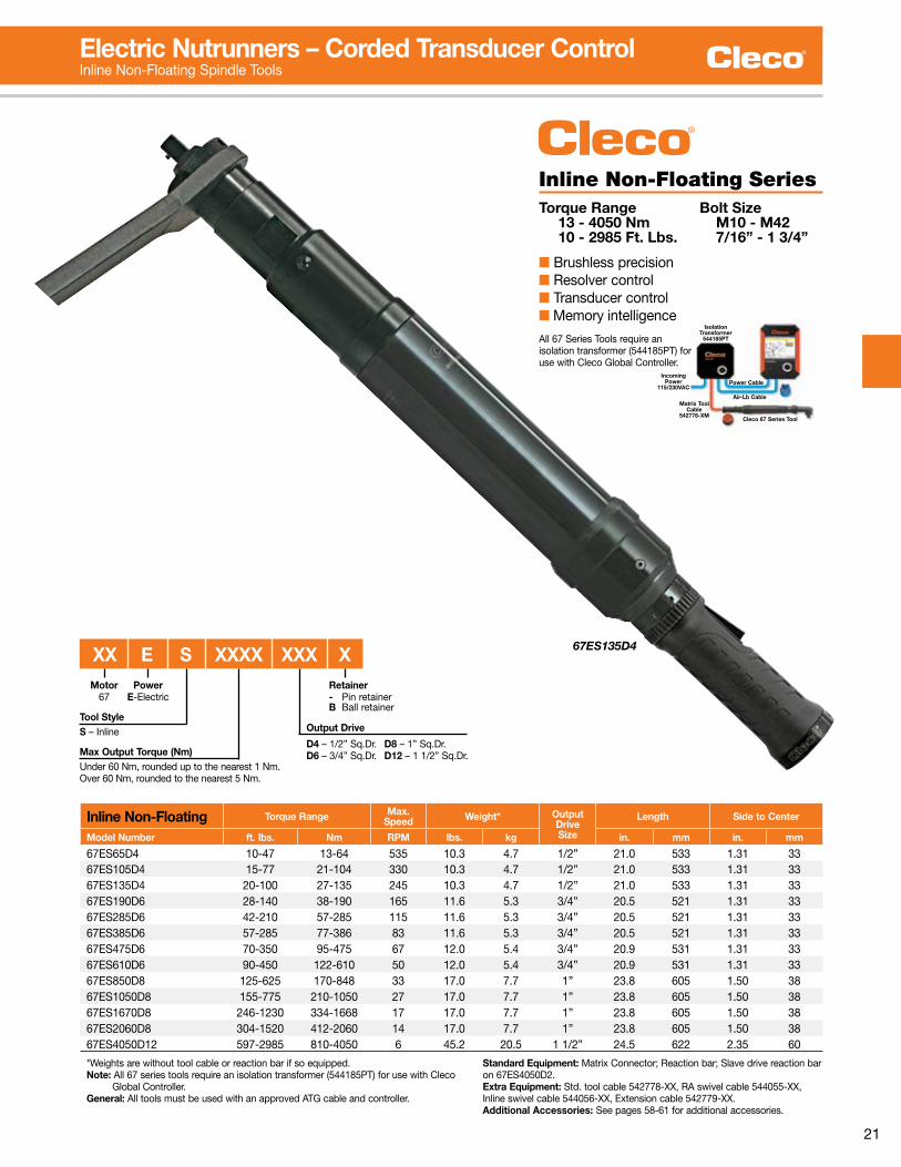
Inline Non-Floating Torque Range Max.Speed Weight* Output
DriveSize
Length Side to Center
Model Number ft. lbs. Nm RPM lbs. kg in. mm in. mm
67ES65D4 10-47 13-64 535 10 .3 4 .7 1/2” 21 .0 533 1 .31 3367ES105D4 15-77 21-104 330 10 .3 4 .7 1/2” 21 .0 533 1 .31 3367ES135D4 20-100 27-135 245 10 .3 4 .7 1/2” 21 .0 533 1 .31 3367ES190D6 28-140 38-190 165 11 .6 5 .3 3/4” 20 .5 521 1 .31 3367ES285D6 42-210 57-285 115 11 .6 5 .3 3/4” 20 .5 521 1 .31 3367ES385D6 57-285 77-386 83 11 .6 5 .3 3/4” 20 .5 521 1 .31 3367ES475D6 70-350 95-475 67 12 .0 5 .4 3/4” 20 .9 531 1 .31 3367ES610D6 90-450 122-610 50 12 .0 5 .4 3/4” 20 .9 531 1 .31 3367ES850D8 125-625 170-848 33 17 .0 7 .7 1” 23 .8 605 1 .50 3867ES1050D8 155-775 210-1050 27 17 .0 7 .7 1” 23 .8 605 1 .50 3867ES1670D8 246-1230 334-1668 17 17 .0 7 .7 1” 23 .8 605 1 .50 3867ES2060D8 304-1520 412-2060 14 17 .0 7 .7 1” 23 .8 605 1 .50 3867ES4050D12 597-2985 810-4050 6 45 .2 20 .5 1 1/2” 24 .5 622 2 .35 60
*Weights are without tool cable or reaction bar if so equipped . Note: All 67 series tools require an isolation transformer (544185PT) for use with Cleco Global Controller . General: All tools must be used with an approved ATG cable and controller .
Standard Equipment: Matrix Connector; Reaction bar; Slave drive reaction bar on 67ES4050D2 . Extra Equipment: Std . tool cable 542778-XX, RA swivel cable 544055-XX, Inline swivel cable 544056-XX, Extension cable 542779-XX .Additional Accessories: See pages 58-61 for additional accessories .
Inline Non-Floating SeriesTorque Range Bolt Size 13 - 4050 Nm M10 - M42 10 - 2985 Ft. Lbs. 7/16” - 1 3/4”
■ Brushless precision■ Resolver control■ Transducer control■ Memory intelligence
67ES135D4
Electric Nutrunners – Corded Transducer ControlInline Non-Floating Spindle Tools
Max Output Torque (Nm)Under 60 Nm, rounded up to the nearest 1 Nm .Over 60 Nm, rounded to the nearest 5 Nm .
Output Drive
D4 – 1/2” Sq .Dr . D8 – 1” Sq .Dr .D6 – 3/4” Sq .Dr . D12 – 1 1/2” Sq .Dr .
Motor67
Tool StyleS – Inline
PowerE-Electric
XX E S XXXX XXX XRetainer- Pin retainerB Ball retainer
Isolation Transformer
544185PT
Incoming Power
115/230VAC
Matrix Tool Cable
542778-XMCleco 67 Series Tool
Air-Lb Cable
Power Cable
All 67 Series Tools require an isolation transformer (544185PT) for use with Cleco Global Controller .

22
Pistol Grip Torque Range Max.Speed Weight* Output
DriveSize
Length Side to Center
Model Number ft. lbs. Nm RPM lbs. kg in. mm in. mm
18EPE06Q 1 .5-4 .4 2-6 4000 2 .2 1 .0 1/4” Hex 7 .0 178 0 .84 2118EPE06D2 1 .5-4 .4 2-6 4000 2 .2 1 .0 1/4” 6 .5 165 0 .84 2118EPE12Q 2 .2-8 .9 3-12 1820 2 .4 1 .1 1/4” Hex 7 .7 196 0 .84 2118EPE12D3 2 .2-8 .9 3-12 1820 2 .4 1 .1 3/8” 7 .2 183 0 .84 2118EPE17Q 3 .0-12 .5 4-17 1290 2 .4 1 .1 1/4” Hex 7 .7 196 0 .84 2118EPE17D3 3 .0-12 .5 4-17 1290 2 .4 1 .1 3/8” 7 .2 183 0 .84 2118EPE22D3 3 .7-16 .2 5-22 985 2 .4 1 .1 3/8” 7 .2 183 0 .84 2118EPE31D3 5 .2-22 .9 7-31 695 2 .4 1 .1 3/8” 7 .2 183 0 .84 2148EPE12Q 2 .2-8 .9 3-12 4000 2 .7 1 .2 1/4” Hex 8 .2 208 0 .84 2148EPE12D2 2 .2-8 .9 3-12 4000 2 .7 1 .2 1/4” 7 .7 196 0 .84 2148EPE25D3 3 .7-18 .4 5-25 1820 2 .9 1 .3 3/8” 8 .4 213 0 .84 2148EPE36D3 5 .9-26 .6 8-36 1290 2 .9 1 .3 3/8” 8 .4 213 0 .84 2148EPE48D3 7 .4-35 .4 10-48 985 3 .0 1 .4 3/8” 8 .6 218 0 .84 2148EPE65D4 9 .6-47 .9 13-65 750 5 .0 2 .3 1/2” 11 .4 290 1 .1 2848EPE90D4 14 .0-66 .4 19-90 510 5 .3 2 .4 1/2” 12 .0 305 1 .1 2848EPE125D4 19 .2-92 .2 26-125 360 5 .3 2 .4 1/2” 12 .0 305 1 .1 2848EPE150D4 22 .9-110 .6 31-150 240 5 .3 2 .4 1/2” 12 .0 305 0 .9 2348EPE200D6 92-144 125-195 180 9 .5 4 .3 3/4” 16 .2 410 1 .13 2948EPE500D6 225-368 300-500 53 9 .8 4 .5 3/4” 16 .2 410 1 .13 2948EPE1000D8 370-740 500-1000 33 16 .2 7 .3 1” 19 .16 486 1 .5 38
*Weights are without tool cable or suspension bail . General: All tools must be used with an approved ATG cable and controller .Standard Equipment: Air-LB Connector; Suspension Bail; Dead Handle is included with 18EPE12Q & 18EPE12D3 . Reaction bar is included with pistol tools with output torques of 17-1000 Nm . Ball retainer optional .Tools with Matrix connector available upon request .
Extra Equipment: Std . tool cable 301866-XX, RA swivel cable 301903-XX, Inline swivel cable 301904-XX, Extension cable 301877-XX .Additional Accessories: See pages 58-61 for additional accessories .
Pistol Grip SeriesTorque Range Bolt Size 2 - 1000 Nm M5 - M22 1.5 - 740 Ft. Lbs. #10 - 1”
■ Brushless precision■ Resolver control■ Transducer control■ Memory intelligence
18EPE12Q
48EPE25D3
Electric Nutrunners – Corded Transducer ControlPistol Grip Tools
Max Output Torque (Nm)Under 60 Nm, rounded up to the nearest 1 Nm .Over 60 Nm, rounded to the nearest 5 Nm .
Motor18, 48
Tool StyleP – Pistol
PowerE-Electric
XX E P E XXX XX X
Output Drive
Q – Quick change D3 – 3/8” Sq .Dr .D2 – 1/4” Sq .Dr . D4 – 1/2” Sq .Dr .D6 – 3/4” Sq .Dr . D8 – 1” Sq .Dr .
Retainer- Pin retainer B Ball retainer
ConnectorAir-LB

23
Push-to-Start SeriesTorque Range Bolt Size 2 - 12 Nm M5 - M6 1.5 - 8.9 Ft. Lbs. #10 - 1/4”
■ Brushless precision■ Resolver control■ Transducer control■ Memory intelligence
Push-to-Start Torque Range Max.Speed Weight* Output
DriveSize
Length Side to Center
Model Number ft. lbs. Nm RPM lbs. kg in. mm in. mm
18EPE06QP 1 .5-4 .4 2-6 4000 2 .66 1 .19 1/4” Hex 9 .35 238 0 .84 2118EPE06D3P 2 .2-8 .9 3-12 4000 2 .66 1 .19 3/8” 8 .8 224 0 .84 2118EPE12QP 2 .2-8 .9 3-12 1820 2 .83 1 .27 1/4” Hex 9 .35 196 0 .84 2118EPE12D3P 2 .2-8 .9 3-12 1820 2 .83 1 .27 3/8” 8 .8 224 0 .84 2118ESE06QP 1 .5-4 .4 2-6 4000 2 .93 1 .31 1/4” Hex 14 .75 375 0 .91 2318ESE06D3P 2 .2-8 .9 3-12 4000 2 .93 1 .31 3/8” 14 .20 360 0 .91 2318ESE12QP 2 .2-8 .9 3-12 1820 3 .10 1 .40 1/4” Hex 14 .75 375 0 .91 2318ESE12D3P 2 .2-8 .9 3-12 1820 3 .10 1 .40 3/8” 14 .20 360 0 .91 23
*Weights are without tool cable or suspension bail . General: All tools must be used with an approved ATG cable and controller .Standard Equipment: Air-LB Connector; Suspension Bail (pistol only); Dead Handle (301857) is included with 18CPE12Q & 18CPE12D3 .Tools with Matrix connector available upon request .
Extra Equipment: Std . tool cable 301866-XX, RA swivel cable 301903-XX, Inline swivel cable 301904-XX, Extension cable 301877-XX .Additional Accessories: See pages 58-61 for additional accessories .
18EPE06QP
18ESE06QP
Electric Nutrunners – Corded Transducer ControlPush-to-Start Pistol Grip/Inline Tools
Max Output Torque (Nm)Under 60 Nm, rounded up to the nearest 1 Nm .
Motor18, 48
Tool StyleP – PistolS – Inline
PowerE-Electric
XX E P E XX XX P
Output Drive
Q – Quick changeD3 – 3/8” Sq .Dr .
Push-to-StartConnectorAir-LB

24
Inline Floating Spindle SeriesTorque Range Bolt Size 2 - 248 Nm M5 - M16 1.5 - 182.9 Ft. Lbs. #10 - 5/8”
■ Brushless precision■ Resolver control■ Transducer control■ Memory intelligence
Inline Floating Spindle Torque Range Max.
Speed Weight* OutputDriveSize
Length Side to Center
Model Number ft. lbs. Nm RPM lbs. kg in. mm in. mm
18ESE06ZA 1 .5-4 .4 2-6 4000 3 .0 1 .4 1/4 15 .5 394 0 .91 2318ESE12ZA 2 .2-8 .9 3-12 1820 3 .2 1 .5 1/4 16 .0 406 0 .91 2318ESE17ZA 3 .0-12 .5 4-17 1290 3 .2 1 .5 1/4 16 .0 406 0 .91 23 48ESE12ZA 2 .2-8 .9 3-12 4000 3 .4 1 .5 1/4 16 .7 425 0 .91 2348ESE271ZB 5 .9-19 .9 8-27 1820 5 .8 2 .6 3/8 22 .0 559 0 .92 2348ESE361ZB 5 .2-26 .6 7-36 1290 5 .8 2 .6 3/8 22 .0 559 0 .92 23 48ESE602ZB 8 .1-42 .0 11-57 855 8 .4 3 .8 1/2 24 .4 620 1 .10 2848ESE702ZB 10 .3-50 .2 14-68 570 8 .4 3 .8 1/2 24 .4 620 1 .10 2848ESE802ZB 12 .5-60 .5 17-82 450 9 .6 4 .4 1/2 26 .7 678 1 .10 3148ESE1152ZB 18 .4-84 .8 25-115 320 9 .6 4 .4 1/2 26 .7 678 1 .10 3148ESE1502ZB 22 .9-110 .6 31-150 245 9 .6 4 .4 1/2 26 .7 678 1 .10 3148ESE1653ZB 24 .3-121 .7 33-165 220 14 .6 6 .6 3/4 28 .6 726 1 .57 4048ESE2503ZB 36 .8-182 .9 50-248 145 14 .6 6 .6 3/4 28 .6 726 1 .57 40
*Weights are without tool cable or reaction bar if so equipped . General: All tools must be used with an approved ATG cable and controller .Standard Equipment: Air-LB Connector . Tool square drives have thru hole output .Tools with Matrix connector available upon request .
Extra Equipment: Std . tool cable 301866-XX, RA swivel cable 301903-XX, Inline swivel cable 301904-XX, Extension cable 301877-XX .Additional Accessories: See pages 58-61 for additional accessories .
48ESE12ZA
1.22”58.87mm
2.318”
1.159”29.43mm
.669”16.99mm
1.339”34.01mm
3.15”80.01mm
31.1mm
1ZBZA 2ZB 3ZB
Dimensional Spindle Float: 1” (25mm) ZA 2” (50mm) 1ZB, 2ZB, 3ZB
tolerances = ± .004” (0.1mm)
0.25”6.3mm
1.22”31.1mm 1.31”
33.3mm1.73”
44.0mm
0.35”9.0mm
1.37”34.9mm
1.41”35.92mm
1.41”35.92mm
2.00”50.8mm
1.97”50.04mm
1.559”39.6mm
1.50”38.1mm
1.10”27.94mm
M5 x 0.8Thd. Typ.
Base Plate Mounting Dimensions
Electric Nutrunners – Corded Transducer ControlInline Floating Spindle Tools
Output Drive
ZA – 1/4” Sq .Dr .1ZB – 3/8” Sq .Dr .2ZB – 1/2” Sq .Dr .3ZB – 3/4” Sq .Dr .
Max Output Torque (Nm)Under 60 Nm, rounded up to the nearest 1 Nm .Over 60 Nm, rounded to the nearest 5 Nm .
Motor18, 48
Tool StyleS – Inline
PowerE-Electric
XX E S E XXX XXXConnector
Air-LB

25
67ES2060Z8
Inline Floating Spindle Torque Range Max.
Speed Weight* OutputDriveSize
Length Side to Center
Model Number ft. lbs. Nm RPM lbs. kg in. mm in. mm
67ES65BZ4 10-47 13-64 535 10 .8 4 .9 1/2 21 .0 533 1 .31 3367ES105BZ4 15-77 21-104 330 10 .8 4 .9 1/2 21 .0 533 1 .31 3367ES135BZ4 20-100 27-135 245 10 .8 4 .9 1/2 21 .0 533 1 .31 3367ES190Z6 28-140 38-190 165 15 .6 7 .1 3/4 22 .0 559 1 .31 3367ES285Z6 42-210 57-285 115 15 .6 7 .1 3/4 22 .0 559 1 .31 3367ES385Z6 57-285 77-386 83 15 .6 7 .1 3/4 22 .0 559 1 .31 3367ES475Z6 70-350 95-475 67 16 .0 7 .3 3/4 22 .4 569 1 .31 3367ES610Z6 90-450 122-610 50 16 .0 7 .3 3/4 22 .4 569 1 .31 3367ES850Z8 125-625 170-848 33 20 .0 9 .1 1 23 .8 605 1 .50 3867ES1050Z8 155-775 210-1050 27 20 .0 9 .1 1 23 .8 605 1 .50 3867ES1670Z8 246-1230 334-1668 17 20 .0 9 .1 1 23 .8 605 1 .50 3867ES2060Z8 304-1520 412-2060 14 20 .0 9 .1 1 23 .8 605 1 .50 38
*Weights are without tool cable or reaction bar if so equipped . Note: All 67 series tools require an isolation transformer (544185PT) for use with Cleco Global Controller . General: All tools must be used with an approved ATG cable and controller .
Standard Equipment: Matrix Connector; 67ES series – Mounting plate . Extra Equipment: Std . tool cable 542778-XX, RA swivel cable 544055-XX, Inline swivel cable 544056-XX, Extension cable 542779-XX .Additional Accessories: See pages 58-61 for additional accessories .
Inline Floating Spindle SeriesTorque Range Bolt Size 13 - 2060 Nm M6 - M36 10 - 1520 Ft. Lbs. 1/4” - 1 1/2”
■ Brushless precision■ Resolver control■ Transducer control■ Memory intelligence
67ES Base Plate Mounting Dimensions
Spindle Float: .69” (17mm)
2 .372”2 .375”
PILOT DIA .
1 .185”
.281” DIA .THRU 2 HOLES
1 .685”
1 .563”
Z4
2 .005”
3 .010”
1 .505”
3/8-24 UNF TH'D DIA .
3 .750”
2 .500”2 .499”
PILOT DIA .
Z6
Spindle Float: .75” (19mm)
4 .000”4 .020”
7/16-20 UNF-2B
TH’D DIA .
5 .000”
4 .000”
2 .000”2 .010”
3 .000”3 .010”
2 .991”2 .990”
PILOT DIA .
Z8
Spindle Float: 1 .0” (25mm)
Electric Nutrunners – Corded Transducer ControlInline Floating Spindle Tools
Motor67
Tool StyleS – Inline
Electric
67 E S XXXX XXOutput DriveZ4 – 1/2” Sq .Dr .Z6 – 3/4” Sq .Dr .Z8 – 1” Sq .Dr .
Max Output Torque (Nm)Under 60 Nm, rounded up to the nearest 1 Nm .Over 60 Nm, rounded to the nearest 5 Nm .
Isolation Transformer
544185PT
Incoming Power
115/230VAC
Matrix Tool Cable
542778-XMCleco 67 Series Tool
Air-Lb Cable
Power CableAll 67 Series Tools require an isolation transformer (544185PT) for use with Cleco Global Controller .

26
Hold & Drive tool approaches the application.
Hold socket fits over bolt and prevents it from rotating.
Tool is pushed down and started until drive socket engages and tightens nut.
Hold & Drive Torque Range FreeSpeed Length Weight* Head Height Side to Center
Model Number Ft.Lbs. Nm RPM in. mm lbs. kg in. mm in. mm
48EAE53H 8 .1 – 39 .1 11 – 53 850 20 .2 512 7 .9 3 .60 2 .40 61 1 .06 2748EAE75H 11 .1 – 54 .6 15 – 74 600 20 .2 512 7 .9 4 .03 2 .40 61 1 .06 2748EAE110H 17 .0 – 82 .6 23 – 112 400 20 .2 512 8 .9 4 .03 2 .40 61 1 .06 2748EAE135H 20 .7 – 98 .8 28 – 134 270 20 .6 522 8 .9 4 .03 2 .40 61 1 .06 2748EAE230H 34 .7 – 167 .4 47 – 227 150 22 .2 563 10 .6 4 .79 2 .40 61 1 .06 27
*Weights are without tool cable and reaction bar . General: All tools must be used with an approved ATG cable and controller .Standard Equipment: Air-LB Connector . Retraction 1” standard for hold bit .Tools with Matrix connector available upon request .
Extra Equipment: Std . tool cable 301866-XX, RA swivel cable 301903-XX, Inline swivel cable 301904-XX, Extension cable 301877-XX .Additional Accessories: See pages 58-61 for additional accessories .
Hold & Drive SeriesTorque Range 11 - 227 Nm 8.1 - 167.4 Ft. Lbs.■ Brushless precision■ Resolver control■ Transducer control■ Memory intelligence 48EAE115H
Electric Nutrunners – Corded Transducer ControlHold & Drive Tools
48 E A E XXX H H X XX X XX XHold & Drive Tool Nomenclature Socket Nomenclature
Max Output Torque
<60 Nm, rounded up to the nearest 1 Nm . >60 Nm, rounded to the nearest 5 Nm .
Retainer Shaft
3 - 3 1/2”4 - 4”5 - 5 3/8”6 - 5 7/8”9 - 9 1/2”
Head TypeH-Hold & Drive
ConnectorAir-LB
Motor48
Tool Style
A – Angle
Electric
Drive Socket Sizes (surface drive)
EH – 11/16 MG – 13mm MM – 19mm (3/4”) MS – 25mmEJ – 13/16 MH – 14mm MN – 20mm MT – 26mmEK – 7/8 MI – 15mm MO – 21mm MU – 27mm (1 1/16”)EM – 1 MJ – 16mm (5/8”) MP – 22mm MX – 30mm (1 3/16”)EO – 1 1/8 MK – 17mm MQ – 23mm MZ – 32mm (1 1/4”) ML – 18mm MR – 24mm (15/16”)
Hold & Drive
Oval Dim. (length)If socket style =0 (female oval)
Socket Style
F – Female HexM – Male HexT – TorxO – Female Oval Hold Socket (width across flats)
EA – 1/4 ME – 11mm (7/16”)EC – 3/8 MF – 12mmM5 – 5mm 15 – T15M6 – 6mm 20 – T20MA – 7mm 25 – T25MB – 8mm (5/16”) 30 – T30MC – 9mm 40 – T40MD – 10mm 45 – T45 50 – T50
Male Oval (length)
Hold Size (width)
Output Drive Size
“Hold & Drive” bolts are used with these tools in automotive and truck frame applications . They reduce assembly handling to one person working from one side of the workpiece . The bolt is held stationary by the tool while the nut is tightened from the same side .

27
Flush Socket SeriesTorque Range Bolt Size 4.9 - 230 Nm M8 - M21 3.6 - 169.6 Ft. Lbs. 1/2” - 1 3/16”
■ Brushless precision■ Resolver control■ Transducer control■ Memory intelligence
18EAE30F1
Flush socket tools have plenty of clearance to fit low clearance applications. Electric flush socket tools tighten with much higher accuracy than tools with crowfoot attachment.
Overall Head Height
Available clearance
Electric Nutrunners – Corded Transducer ControlFlush Socket Tools
Flush Socket Head
TypeTorque Range Free
Speed Weight* LengthAnglehead
Side to Center Height
Model Number ft. lbs. Nm RPM lbs. kg in. mm in. mm in. mm
18EAE16F F1 3 .6-11 .8 4 .9-16 1225 4 .4 2 .00 16 .0 406 0 .55 14 1 .54 3918EAE23F F1 3 .4-17 .0 4 .6-23 860 4 .4 2 .00 16 .0 406 0 .55 14 1 .54 3918EAE30F F1 4 .4-22 .1 6 .0-30 655 4 .4 2 .00 16 .0 406 0 .55 14 1 .54 3948EAE37F F2 5 .9-27 .3 8 .0-37 1225 5 .4 2 .43 18 .7 474 0 .67 17 1 .69 4348EAE52F F2 8 .1-38 .3 11-52 860 5 .4 2 .43 18 .7 474 0 .67 17 1 .69 4348EAE53F F3 8 .1-39 .0 11-53 850 6 .0 2 .74 20 .0 509 0 .87 22 2 .32 5948EAE75F F3 11 .1-55 .3 15-75 600 6 .0 2 .74 20 .0 509 0 .87 22 2 .32 5948EAE110F F3 17 .0-81 .1 23-110 400 7 .4 3 .38 20 .5 521 0 .87 22 2 .32 5948EAE135F F4 19 .9-99 .5 27-135 270 8 .9 4 .03 20 .6 522 1 .06 27 2 .40 6148EAE230F F4 34 .7-169 .6 47-230 150 10 .6 4 .79 22 .2 563 1 .06 27 2 .40 61
*Weights are without tool cable or reaction bar if so equipped . General: All tools must be used with an approved ATG cable and controller .Standard Equipment: Air-LB Connector .Tools with Matrix connector available upon request .
Extra Equipment: Std . tool cable 301866-XX, RA swivel cable 301903-XX, Inline swivel cable 301904-XX, Extension cable 301877-XX .Additional Accessories: See pages 58-61 for additional accessories .
FSX XX X X
Head Type
F1 Head 8–15mm socket capacityF2 Head 10–15mm socket capacityF3 Head 13–21mm socket capacityF4 Head 13–21mm socket capacity
Motor1848 Tool Style
A – Right Angle
Electric ConnectorAir-LB
Output Type
0–Standard 1–Fast Lead 2–Magnetic
Extension Length
0 – Flush 4 – 1/2” 8 – 1”2 – 1/4” 6 – 3/4”
Flush Socket Tool Nomenclature Socket Nomenclature
XX E A E XXX FX
Socket Size
EC – 3/8 MB – 8mm (5/16) MJ – 16mm (5/8”)EE – 1/2 MD – 10mm MK – 17mmEF – 9/16 ME – 11mm (7/16) ML – 18mmEH – 11/16 MF – 12mm MM – 19mm (3/4”)EJ – 13/16 MG – 13mm MN – 20mm MH – 14mm MO – 21mm MI – 15mm
X Dimension For Flush SocketHead in. mm Socket Size Range
F1 1 .54 39 8–15mmF2 1 .69 43 10–15mmF3 2 .32 59 13–21mmF4 2 .4 61 17–21mm
Max Output Torque
F1 16,23, 30 Nm F3 53, 75, 110 NmF2 37, 52 Nm F4 135, 230 Nm<60 Nm, rounded up to the nearest 1 Nm . >60 Nm, rounded to the nearest 5 Nm .
Flush Socket
1 F12 F23 F34 F4
28
T2
T3
T4
“B”T2, T3 & T4Head Height
“A”
2.63” (67 mm) 1.56” (40 mm)T2 Head T3 Head
1.44” (37 mm)
“A”“C”
“D”
T4 Head
1.94” (49 mm)
“A”“C”
“D”
“C”
“D”
Tube Nut Max.DriveSize
Torque Range FreeSpeed Weight* Length
Head
A Width B Blade Ht. C Opening D End/Cntr.
Model Number Ft.Lbs. Nm RPM lbs. kg in. mm in. mm in. mm in. mm in. mm
48ETE20T2 1/2” 7 .4-14 .8 10-20 1425 4 .4 2 .0 16 .9 430 1 .42 36 0 .55 14 0 .28 7 0 .53 1348ETE30T3 3/4” 11 .1-22 .1 15-30 1030 4 .5 2 .0 16 .6 422 1 .65 42 0 .59 15 0 .475 13 0 .73 1948ETE40T4 1 1/16” 14 .8-29 .5 20-40 770 5 .3 2 .3 17 .9 454 2 .36 60 0 .59 15 0 .675 18 0 .93 24
*Weights are without tool cable and reaction bar . General: All tools must be used with an approved ATG cable and controller .Standard Equipment: Air-LB Connector .Tools with Matrix connector available upon request .
Extra Equipment: Std . tool cable 301866-XX, RA swivel cable 301903-XX, Inline swivel cable 301904-XX, Extension cable 301877-XX .Additional Accessories: See pages 58-61 for additional accessories .
Tube Nut SeriesTorque Range Bolt Size 10 - 40 Nm M6 - M10 7.4 - 29.5 Ft. Lbs. 1/4” - 3/8”
■ Brushless precision■ Resolver control■ Transducer control■ Memory intelligence
The 48ET tube nut wrench alternates the direction of rotation each time the lever is actuated. When rotating in reverse, the socket will stop at the open position.
Note: To order individual sockets, use a “KS” prefix (i .e . KS2EA01 for a T2 1/4”, Flush, Thru Hex socket .)
Electric Nutrunners – Corded Transducer ControlTube Nut Tools
Tube Nut Tool Nomenclature Socket Nomenclature
Max Output Torque<60 Nm, rounded up to the nearest 1 Nm .
Head TypeT2 - 20 NmT3 - 30 NmT4 - 40 Nm
Motor48
ConnectorAir-LB
Tool StyleT – Tube Nut
Electric Output Type
0 -Partial Thru Hex 2 -Double Thru Hex1 -Thru Hex 3 -Partial Thru Double Hex
Extension Length
0 – Flush 4 – 1/2” 8 – 1”2 – 1/4” 6 – 3/4”
Maximum Hex Socket Size
MG, EE T2 Head TypeMM, 3/4” T3 Head TypeMU, 1 1/16” T4 Head Type00, ## (Specials) All Head Types
Thru Hex DoubleThru Hex
PartialThru Hex
Partial Thru Double Hex
Head TypeKS2 – T2KS3 – T3KS4 – T4
XX E T E XX XX KSX XX XX X
Socket Sizes
EA - 1/4” M5 – 5mm MH – 14mm MP – 22mmEC – 3/8 M6 – 6mm MI – 15mm MQ – 23mmEE – 1/2 MA – 7mm MJ – 16mm (5/8) MR – 24mm (15/16)EF – 9/16 MB – 8mm (5/16) MK – 17mm MS – 25mmEH – 11/16 MD – 10mm ML – 18mm MT – 26mmEJ – 13/16 ME – 11mm (7/16) MM – 19mm (3/4) MU – 27mm (1 1/16)EK – 7/8 MF – 12mm MN – 20mmEM – 1 MG – 13mm MO – 21mm

29
48ECE30C 1
Crowfoot Torque Range FreeSpeed Weight* Length
Model Number15° Head 30° Head ft. lbs. Nm RPM lbs. kg in. mm
48ECE30C1 48ECE30C3 5 .2-22 .1 10 .5-30 860 5 .5 2 .3 20 .5 521
*Weights are without tool cable and reaction bar . General: All tools must be used with an approved ATG cable and controller .Standard Equipment: Air-LB Connector .Tools with Matrix connector available upon request .
Extra Equipment: Std . tool cable 301866-XX, RA swivel cable 301903-XX, Inline swivel cable 301904-XX, Extension cable 301877-XX .Additional Accessories: See pages 58-61 for additional accessories .
To order individual sockets, use “CS” prefix before the required socket . (i .e . CSEA01 for a 1/4”, flush, thru hex socket .)
Crowfoot SeriesTorque Range Bolt Size 7 - 30 Nm M6 - M8 5 - 22 Ft. Lbs. #10 - 3/8”
■ Brushless precision■ Resolver control■ Transducer control■ Memory intelligence
Electric Nutrunners – Corded Transducer ControlCrowfoot Tools
Max Output Torque<60 Nm, rounded up to the nearest 1 Nm .
Head TypeC1 - 15° CrowfootC3 - 30° Crowfoot
Motor48
Tool StyleC – Crowfoot
Electric
Socket SizeEA – 1/4” MC – 9mmEC – 3/8 MD – 10mmEE – 1/2 ME – 11mm (7/16)EF – 9/16 MF – 12mmMA – 7mm MG – 13mmMB – 8mm (5/16) MH – 14mm MI – 15mm* *Fragile. Light duty apps.
Socket NomenclatureCrowfoot Tool Nomenclature
Output Style1 – Thru Hex
Socket TypeCS – Crowfoot
Extension Length0 – Flush4 – 1/2”6 – 3/4”
48 E C E XX XX CS XX XX X
.61”(15.49)
.97”(24.63)
.75”(19)
3.00”(76.2)
30°
R.63”(16)
1.25”(31.75)
1.50”(38.1)
.25”(6.35)
C3 – 30° Head (Part No. 301960)Maximum Recommended Torque: 22 ft .lbs . (30 Nm)
15°
.61”(15.49)
1.09”(27.86)
.75”(19)
3.00”(76.2)
2.66”(67.56)
1.50”(38.1)
1.25”(31.75)
R.63”(16)
.25”(6.35)
C1 – 15° Head (Part No. 301959)Maximum Recommended Torque: 22 ft .lbs . (30 Nm)

30
Right Angle Floating Spindle SeriesTorque Range Bolt Size 5.1 - 255 Nm M7 - M18 3.7 - 188.1 Ft. Lbs. 1/4” - 3/4”
■ Brushless precision■ Resolver control■ Transducer control■ Memory intelligence
Right Angle Floating Spindle Torque Range Max.
Speed Weight* OutputDriveSize
Length Side to Center
Model Number ft. lbs. Nm RPM lbs. kg in. mm in. mm
18EAE16S131 3 .7-11 .8 5 .1-16 1225 4 .4 2 .00 3/8” 16 .0 406 0 .55 1418EAE23S131 5 .3-16 .9 7 .2-23 860 4 .4 2 .00 3/8” 16 .0 406 0 .55 1418EAE30S131 4 .4-22 .1 6 .0-30 655 4 .4 2 .00 3/8” 16 .0 406 0 .55 1448EAE37S231 5 .9-27 .2 8 .0-37 1225 5 .4 2 .43 3/8” 18 .7 474 0 .67 1748EAE52S231 8 .1-38 .3 11-52 860 5 .4 2 .43 3/8” 18 .7 474 0 .67 1748EAE53S341 8 .1-39 .1 11-53 850 6 .0 2 .74 1/2” 20 .0 509 0 .87 2248EAE75S341 11 .0-55 .3 15-75 600 6 .0 2 .74 1/2” 20 .0 509 0 .87 2248EAE95S341 14 .7-70 .0 20-95 460 7 .4 3 .38 1/2” 20 .5 521 0 .87 2248EAE110S341 16 .9-81 .1 23-110 400 7 .4 3 .38 1/2” 20 .5 521 0 .87 2248EAE135S461 20 .6-99 .5 28-135 270 8 .9 4 .03 3/4” 20 .6 522 1 .06 2748EAE230S461 34 .6-169 .6 47-230 150 10 .6 4 .79 3/4” 22 .2 563 1 .06 2767EA150S461 22 .1-110 .6 30-150 210 12 .9 5 .90 3/4” 25 .8 655 1 .03 2667EA185S461 27 .3-136 .3 37-185 170 12 .9 5 .90 3/4” 25 .8 655 1 .03 2667EA210S461 31 .0-154 .8 42-210 155 12 .9 5 .90 3/4” 25 .8 655 1 .03 2667EA235S461 33 .9-169 .6 46-230 135 12 .9 5 .90 3/4” 25 .8 655 1 .03 2667EA255S461 40 .6-188 .1 55-255 115 12 .9 5 .90 3/4” 25 .8 655 1 .03 26
*Weights are without tool cable and mounting plate . Note: All 67 series tools require an isolation transformer (544185PT) for use with Cleco Global Controller . General: All tools must be used with an approved ATG cable and controller .Standard Equipment: 18/48 tools; Air-LB Connector; Mounting plate . Tools with Matrix connector available upon request . 67 tools; Matrix Connector; Mounting plate
Extra Equipment: 18/48 tools; Std . tool cable 301866-XX, RA swivel cable 301903-XX, Inline swivel cable 301904-XX, Extension cable 301877-XX .67 tools; Std . tool cable 542778-XX, RA swivel cable 544055-XX, Inline swivel cable 544056-XX, Extension cable 542779-XX .Additional Accessories: See pages 58-61 for additional accessories .
48EAE135S461
Max Output Torque
S1 Head – 16, 23, or 30 NmS2 Head – 37 or 52 NmS3 Head – 53, 75, 95, or 110 NmS4 Head – 135 or 230 Nm (48 series)S4 Head – 150, 185, 210, 235 or 255 Nm (67 series)
Tool Termination
S1 Sliding (Floating) Spindle S3 Sliding (Floating) SpindleS2 Sliding (Floating) Spindle S4 Sliding (Floating) Spindle
Motor184867
ConnectorE - Air-LB
Tool StyleA – Right Angle
Electric
XX E A X XXX XX X XExtension Length
1 –1 .13” (S1), 1 .00” (S2 & S3), 1 .25” (S4)2 –2 .13” (S1), 3 .00” (S2), 2 .5” (S4 1/2” Dr .)5 –5 .13” (S2), 4 .25” (S4)6 – 6 .0” (S4 1/2” Dr .), 7 .0” (S4 3/4” Dr .)11 – 11 .0” (S4 3/4” Dr .)
Square Drive3 – 3/8” (S1, S2)4 – 1/2” (S3, S4)6 – 3/4” (S4)
Right Angle Floating Spindle Tool Nomenclature
Electric Nutrunners – Corded Transducer ControlRight Angle Floating Spindle Tools
Isolation Transformer
544185PT
Incoming Power
115/230VAC
Matrix Tool Cable
542778-XMCleco 67 Series Tool
Air-Lb Cable
Power Cable
All 67 Series Tools require an isolation transformer (544185PT) for use with Cleco Global Controller .

31
S3 Head Extension Length “X”1 –1 .0” (1/2” Sq . Dr .)
S4 Head Extension Length “X”1 –1 .25” (1/2” & 3/4” Sq . Dr .)2 –2 .5” (1/2” Sq . Dr .)5 –4 .25” (1/2” & 3/4” Sq . Dr .)6 –6 .0” (1/2” Sq . Dr .)6 –7 .0” (3/4” Sq . Dr .)11 –11 .0” (3/4” Sq . Dr .)
18EA, 48EA & 67EA Floating Spindle Angle Heads
S1 Head Extension Length “X”1 –1 .13” (3/8” Sq . Dr .)2 –2 .13” (3/8” Sq . Dr .)
S2 Head Extension Length “X”1 –1 .0” (3/8” Sq . Dr .)2 –3 .0” (3/8” Sq . Dr .)5 –5 .13” (3/8” Sq . Dr .)
Electric Nutrunners – Corded Transducer ControlRight Angle Floating Spindle Tools

32
Label Printer
Ethernet TCP/IP
System Bus
Fieldbus
Tool
Serial – RS232
Serial – RS232
Discrete I/O – 24vdc
Serial – RS232
Serial – RS232
Socket Tray
Wireless Torque Wrench
Operator ID
BarcodeScanner
Cleco mPro400GC Global Controller
The Most Flexible, Cost-Effective Systems Controller ... EverIntroducing the Cleco mPro400GC Global Controller, the first controller for safety-critical applications that offers unsurpassed levels of flexibility, connectivity, and serviceability while providing superb torque accuracy and process control. This new controller incorporates the advanced technical features of the proven DGD mPro system with the user-friendly software of the trusted Cleco TME controller, resulting in a powerful control solution that offers impressive cost savings through unequalled flexibility.
Corded, Cordless, Or Fixtured ... All From One ControllerThe Cleco mPro400GC GlobalControlleriscompatiblewithallCleco18-48SeriesDCelectriccordedtools, LiveWire cordless tools, and all DGD and EMT fixtured spindles. That means fewer controllers and cablesareneededforyourline.Andthatmeanssavings…upto50%overtraditionalsystems.
Reduce System Costs Up To 50%■Configureupto32DC spindles in varying configurations. Consult your Apex representative for details.
■Facility Cost Savings • Installation Expenses: Save on Ethernet and power drops, controller stands, cable management, labor to install and support • Production Expenses: One controller means fewer backups, fewer repairs, fewer headaches and one-time training

33
Control System
Customer Control System
Corded Hand Tool
DGD Conventional Spindles
DGD Intelligent SpindlesUnique Technology, Smallest Hardware Foot Print, Best TCO.
Power/CPM
Up to 10 LiveWire ToolsTo 1 Controller
Data Server mPro RemoteProgramming
AccessPoint
The Most Flexible, Cost-Effective Systems Controller ... Ever

34
Cleco mPro400GC Global Controller
Universal connectivity begins with global auto-sensinginputvoltage,16configurableinputsandoutputs,plusDeviceNet,Ethernet-IP,ProfibusandProfinet fieldbus standards. User-friendly software mapping of discrete and fieldbus selections provides ultimate error-proofing control. Dual fieldbus ports allow redundant I/O mapping or expansion. Utilize two different fieldbus standards simultaneously for maximum flexibility.
The Cleco mPro400GC Global Controller comes standard with a system bus to manage internal data flow and avoid burdening outside networks. It can be utilized for rapid “grab and go” connectivity to accessories, such as adding error-proofing
from socket trays, stack lights, or operator boxes. Configurable software menus allow quick integration intoanyprocess.Withupto32configurablenodes
on the system bus, endless error-proofing combinations are possible.
The system bus can manage multiple secondary controllers in combination with single and multi-spindle stations. Spindle sequencing, data management, and diagnostics are just a few of the many functions performed. In addition, DGD® Fixtured Intelligent Spindles can
utilizethesystembustodriveupto30%ofcostoutof a traditional system through cable reduction, maximizing acquisition and facility cost savings.
Universal Connectivity For Ultimate Flexibility
Ethernet Connections (2)
USB Ports(2 bottom, 1 front)
System Bus Connection
Auto-Sensing Voltage Input
GFCI
Serial Ports (2)
Digital Input/Output (16)
Redundant Fieldbus Interface
Tool Cable Connector
Universal Connectivity
■ Auto-Sensing Voltage■ 16 Configurable I/O’s■ Redundant Fieldbus■ Redundant Serial and Ethernet Ports■ Isolated System Bus
35
RemoteProgramming
EthernetTCP/IP
Universal Connectivity For Ultimate Flexibility
User Friendly
GUI
Quick-Start Auto
Program Option
Oscilloscope Process Management
In-Depth Data Management
Easy-To-Read Run
Screen
Digital Image Bolt Sequencing
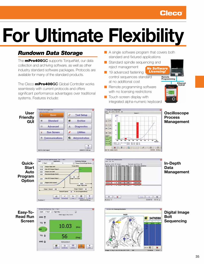
Rundown Data Storage The mPro400GCsupportsTorqueNet,ourdatacollection and archiving software, as well as otherindustry standard software packages. Protocols are available for many of the standard products.
The Cleco mPro400GC Global Controller works seamlessly with current protocols and offers significant performance advantages over traditional systems. Features include:
■ A single software program that covers both standard and fixtured applications
■ Standard spindle sequencing and reject management
■ 19 advanced fastening control sequences standard at no additional cost
■ Remote programming software with no licensing restrictions
■ Touch screen display with integrated alpha-numeric keyboard
No SoftwareLicensing!

36
Cleco mPro400GC Global Controller
Superior Serviceability For Exceptional Ease-Of-Use
Master/Primary Unit
Installation FlexibilityAtonly10”wX15”hX15”d(254mmX381mmX381mm)andweighingjust30lbs.(13.6kg.),theClecomPro400GC is smaller and lighter than mosttraditional controllers. It can be lifted easily by a single person and will mount just about anywhere.
10”x15”x15” (254mm X 381mm X 381mm)
And Just
30 lbs. (13.6 kg.)

37
Superior Serviceability For Exceptional Ease-Of-Use
Secondary Unit
Quick Mount BracketNomoretemplatesandmeasuringmountingholepatterns...installationofthemPro400GC is simple with a separate receiver bracket that makes locating mounting holes easy. The unit then attaches directly to the bracket so the installation is fast and foolproof.
Integrated Cable ManagementThe mPro400GC mounting bracket incorporates an integral cable management channel, so installations stay orderly and easily accessible. Clearly labeled connectors and top-down cable routing means a clean installation with no guesswork. Mounting was designed to be simple and effective to get you up and running fast.
CompactFlash® Memory For Production UptimeA standard CompactFlash card reliably stores:■ Operating system■ Drivers ■Networksettings■ Application parameters■ Torque data
Positioned on the back of the unit for added security and tamper resistance, the card is still easily accessible. ■ Rapid controller swap with 50-second boot■Nolicensingorproprietaryhardware■ Card stores a minimum of 10,000 rundowns per tool
Secondary Controller FunctionalityA secondary controller is controlled from a master or primary unit. It has I/O for local error proofing and peripherals, plus a LCD for operator feedback and troubleshooting.
50 Second Boot!

38
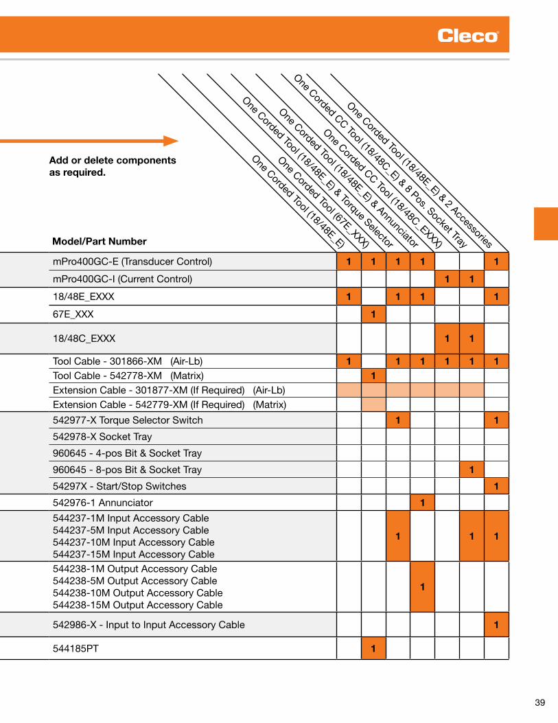
How To Build A DC Global Controller SystemmPro400GC-E & mPro400GC-I
Building a DC Global Controller System is as simple as 1, 2, 3!
1. Choose a common system to the right. 2. Select the correct components below. 3. Order your System!
Controller (Page 10)mPro400GC-E (Transducer Control) 1 1 1 1 1
mPro400GC-I (Current Control) 1 1
Corded Tool, Transducer Control (Page 15)
18/48E_EXXX 1 1 1 1
67E_XXX 1
Corded Tool, Current Control (Page 15)
18/48C_EXXX 1 1
Cable (Page 23)
Tool Cable - 301866-XM (Air-Lb) 1 1 1 1 1 1Tool Cable - 542778-XM (Matrix) 1Extension Cable - 301877-XM (If Required) (Air-Lb)Extension Cable - 542779-XM (If Required) (Matrix)
Input Accessories (Page 41)
542977-X Torque Selector Switch 1 1
542978-X Socket Tray
960645 - 4-pos Bit & Socket Tray
960645 - 8-pos Bit & Socket Tray 1
54297X - Start/Stop Switches 1
Output Accessories (Page 41) 542976-1 Annunciator 1
Input Accessory Cables (Page 42)
544237-1M Input Accessory Cable544237-5M Input Accessory Cable544237-10M Input Accessory Cable544237-15M Input Accessory Cable
1 1 1
Output Accessory Cables (Page 42)
544238-1M Output Accessory Cable544238-5M Output Accessory Cable544238-10M Output Accessory Cable544238-15M Output Accessory Cable
1
Input to Input Accessory Cables (Page 14) 542986-X - Input to Input Accessory Cable 1
Isolation Transformer (Page 11) 544185PT 1
(Refer to Pages 4-5 to build a mPro400GC-M/GC-P/GC-S system.)
39
Controller (Page 10)mPro400GC-E (Transducer Control) 1 1 1 1 1
mPro400GC-I (Current Control) 1 1
Corded Tool, Transducer Control (Page 15)
18/48E_EXXX 1 1 1 1
67E_XXX 1
Corded Tool, Current Control (Page 15)
18/48C_EXXX 1 1
Cable (Page 23)
Tool Cable - 301866-XM (Air-Lb) 1 1 1 1 1 1Tool Cable - 542778-XM (Matrix) 1Extension Cable - 301877-XM (If Required) (Air-Lb)Extension Cable - 542779-XM (If Required) (Matrix)
Input Accessories (Page 41)
542977-X Torque Selector Switch 1 1
542978-X Socket Tray
960645 - 4-pos Bit & Socket Tray
960645 - 8-pos Bit & Socket Tray 1
54297X - Start/Stop Switches 1
Output Accessories (Page 41) 542976-1 Annunciator 1
Input Accessory Cables (Page 42)
544237-1M Input Accessory Cable544237-5M Input Accessory Cable544237-10M Input Accessory Cable544237-15M Input Accessory Cable
1 1 1
Output Accessory Cables (Page 42)
544238-1M Output Accessory Cable544238-5M Output Accessory Cable544238-10M Output Accessory Cable544238-15M Output Accessory Cable
1
Input to Input Accessory Cables (Page 14) 542986-X - Input to Input Accessory Cable 1
Isolation Transformer (Page 11) 544185PT 1
One Corded Tool (18/48E_E)
One Corded Tool (67E_XXX)
One Corded Tool (18/48E_E) & Torque Selector
One Corded Tool (18/48E_E) & Annunciator
One Corded CC Tool (18/48C_EXXX)
One Corded CC Tool (18/48C_E) & 8 Pos. Socket Tray
One Corded Tool (18/48E_E) & 2 AccessoriesModel/Part Number
Add or delete components as required.

40
Cleco mPro400GC Global ControllerMaster, Primary & Secondary
mPro400GC Global Controller■ Graphics interface■ Fully programmable■ Local storage of 10,000 cycles■ LAN capable■ Fieldbus options available
Weight Width Height Depth
Model Description Tool Compatibility lbs. kg in. mm in. mm in. mm
MPRO400GC-P Primary Cleco 18-48 Series, LiveWire, Intelligent Spindle* 30 .7 13 .9 10 .3 261 .62 14 .9 378 .46 12 .9 327 .66
MPRO400GC-P-12 Primary 1-2 LiveWire, Intelligent Spindle*, DGD/EMT Fixtured Spindles - Size 1-2 30 .7 13 .9 10 .3 261 .62 14 .9 378 .46 12 .9 327 .66
MPRO400GC-P-34 Primary 3-4 LiveWire, Intelligent Spindle*, DGD/EMT Fixtured Spindles - Size 3-4 30 .7 13 .9 10 .3 261 .62 14 .9 378 .46 12 .9 327 .66
MPRO400GC-S Secondary Cleco 18-48 Series 28 .1 12 .7 10 .3 261 .62 14 .9 378 .46 12 .9 327 .66
MPRO400GC-S-12 Secondary 1-2 DGD/EMT Fixtured Spindles - Size 1-2 28 .1 12 .7 10 .3 261 .62 14 .9 378 .46 12 .9 327 .66
MPRO400GC-S-34 Secondary 3-4 DGD/EMT Fixtured Spindles - Size 3-4 28 .1 12 .7 10 .3 261 .62 14 .9 378 .46 12 .9 327 .66
MPRO400GC-M Master LiveWire, Intelligent Spindle* 23 .3 10 .6 10 .3 261 .62 14 .9 378 .46 12 .9 327 .66
* Requires quote to accommodate hardware configurations .Note: 17/47/67 and Matrix versions of the 18/48 series tools require Isolation Transformer 544185PT for use with Primary/Secondary controllers .
Master/Primary Unit Secondary Unit
MPRO400GC-M
MPRO400GC-P MPRO400GC-P-1-2 MPRO400GC-S MPRO400GC-S-1-2

41
Cleco mPro400GC-E Global ControllerTorque Control
Weight Width Height Depth
Model Description Tool Compatibility lbs. kg in. mm in. mm in. mm
MPRO400GC-E Torque Control Cleco 18-48 EXE Series Series* 32 .8 72 .3 10 .3 261 .62 14 .9 378 .46 12 .9 327 .66
*Note: 17/47/67 and Matrix versions of the 18/48 series tools require Isolation Transformer 544185PT for use with GC-E model . Standard Equipment: TM-COM Remote Programming Software and a Null Modem Serial Cable .
Torque ControlmPro400GC-E Global Controller■ Single channel■ Economical■ Remote programming■ Local storage of 5,000 cycles■ LAN capable■ Input Voltage: 115/230VAC■ Connections: (1) Serial, (1) TM-COM, (1) Ethernet■ Inputs/Outputs: (8) 24V Inputs, (8) 24V Outputs
MPRO400GC-E
Isolation Transformer
544185PT
Incoming Power
115/230VAC
Matrix Tool Cable
542778-XMCleco 67 Series Tool
Air-Lb Cable
Power Cable
All 67 Series Tools require an isolation transformer (544185PT) for use with Cleco Global Controller .

42
Durability. Speed. Ergonomics.Cost Effective Solution for Quality Critical Applications.Cleco CurrentControl electric assembly tools provide an up-sell solution to quality critical applications presently specifying a pneumatic clutch tool and verifier combination. Cleco proprietary CurrentControl systems up-sell on superior productivity, error proofing and process flexibility.
Our Cleco controller systems are recognized globally for “best in class” software interface. This is accomplished through simple navigation, basic programming screens, visual programming graphics and real-time process feedback. Our latest innovation “Auto Program” takes the guesswork out of programming. Simply enter the application torque target and the software automatically compiles the program for production use.
Adjustable angle head
allows flexible
orientation
Unrestricted Speed Control
Electric Nutrunners – Corded Current Control

43
Durability. Speed. Ergonomics.Why CurrentControl vs. Pneumatic Clutch? Superior Productivity
■Upto2–3Xfaster■ Unrestricted speed control■Upto25%lessnoise■ Cleaner operating environment■ Auto torque sequencing■ Proven production durability
Superior Process Flexibility
■ 255 programmable tightening strategies■6configurablestagesperstrategy■ Angle process control/monitoring■ Counter-clockwise process control/monitoring■ Less parts to maintain – no clutch■ 100M field cable lengths
Superior Error Proofing
■96positionfastenercount■ 9 tool LED operator feedback■8configurableI/O■ Fieldbus ready■ 5,000 tightening cycle storage■ Advanced system diagnostics■ Barcode application select
Easy Setup 1-2-3-Go!1. Select “Basic” from menu. 2. Enter final torque value.
3. Tool automatically programmed. Go! Production ready.

44
18CAE28AM3
48CAE58AM3
Right Angle SeriesTorque Range 2 - 230 Nm 1.5 - 170 Ft. Lbs.Bolt Size M5 - M16 #10 - 5/8”
■ Brushless precision■ Resolver control■ Memory intelligence
Right Angle Torque Range Max.Speed Weight* Output
DriveSize
LengthAnglehead
Side to Center HeightModel Number ft. lbs. Nm RPM lbs. kg in. mm in. mm in. mm
18CAE08AL2 1 .5-5 .9 2-8 3000 2 .9 1 .3 1/4” 13 .6 345 0 .51 13 1 .4 3618CAE15AM3 3 .0-11 .1 4-15 1300 3 .3 1 .5 3/8” 14 .8 376 0 .59 15 1 .6 4118CAE22AM3 3 .7-16 .2 5-22 920 3 .3 1 .5 3/8” 14 .8 376 0 .59 15 1 .6 4118CAE28AM3 4 .4-20 .7 6-28 700 3 .3 1 .5 3/8” 14 .8 376 0 .59 15 1 .6 4148CAE15AL3 2 .2-11 .1 3-15 2855 3 .8 1 .7 3/8” 15 .7 398 0 .59 15 1 .6 4148CAE28AL3 4 .4-20 .7 6-28 1300 4 .1 1 .9 3/8” 16 .2 410 0 .59 15 1 .6 4148CAE41AM3 6 .6-30 .2 9-41 1090 4 .3 2 .0 3/8” 17 .3 440 0 .75 19 1 .9 4848CAE58AM3 8 .9-42 .8 12-58 770 4 .3 2 .0 3/8” 17 .3 440 0 .75 19 1 .9 4848CAE58AM4 8 .9-42 .8 12-58 770 4 .3 2 .0 1/2” 17 .3 440 0 .75 19 1 .9 4848CAE90AH4 13 .3-64 .2 18-87 515 6 .6 3 .0 1/2” 18 .5 470 0 .81 21 2 .3 5848CAE105AH4 15 .5-76 .7 21-104 340 6 .6 3 .0 1/2” 18 .5 470 0 .81 21 2 .3 5848CAE135MH4 19 .9-98 .1 27-133 265 7 .3 3 .3 1/2” 19 .1 485 0 .94 24 2 .4 6148CAE175AX6 26 .6-129 .8 36-176 190 10 .2 4 .6 3/4” 21 .6 549 1 .06 27 2 .7 6948CAE230AX6 33 .9-169 .6 46-230 145 10 .2 4 .6 3/4” 21 .6 549 1 .06 27 2 .7 69
*Weights are without tool cable and reaction bar . General: All tools must be used with an approved ATG cable and controller .Standard Equipment: Air-LB Connector . Ball retainer optional .
Extra Equipment: Std . tool cable 301866-XX, RA swivel cable 301903-XX, Inline swivel cable 301904-XX, Extension cable 301877-XX .Additional Accessories: See pages 58-61 for additional accessories .
Electric Nutrunners – Corded Current ControlRight Angle Tools
Tool StyleA – Right Angle
Current Control
XX C A E XXX XXX XRetainer- Pin retainer B Ball retainer
Output Drive
AL2 – 1/4” Sq .Dr . AM4 – 1/2” Sq .Dr .AL3 – 3/8” Sq .Dr . AH4 – 1/2” Sq .Dr .AM3 – 3/8” Sq .Dr . MH4 – 1/2” Sq .Dr . AX6 – 3/4” Sq .Dr .
ConnectorE-Air-LB
Motor18, 48
Max Output Torque (Nm)Under 60 Nm, rounded up to the nearest 1 Nm .Over 60 Nm, rounded to the nearest 5 Nm .

45
18CSE06Q
48CSE25D3
Inline Non-Floating SeriesTorque Range 2 - 150 Nm 1.5 - 113 Ft. Lbs.Bolt Size M5 - M14 #10 - 5/8”
■ Brushless precision■ Resolver control■ Memory intelligence
Inline Non-Floating Torque Range Max.Speed Weight* Output
DriveSize
Length Side to Center
Model Number ft. lbs. Nm RPM lbs. kg in. mm in. mm
18CSE06Q 1 .5-4 .4 2-6 4000 2 .5 1 .1 1/4” Hex 12 .3 312 0 .91 2318CSE06D2 1 .5-4 .4 2-6 4000 2 .5 1 .1 1/4” 11 .8 300 0 .91 2318CSE12Q 2 .2-8 .9 3-12 1820 2 .7 1 .2 1/4” Hex 13 .0 330 0 .91 2318CSE12D3 2 .2-8 .9 3-12 1820 2 .7 1 .2 3/8” 12 .4 315 0 .91 2318CSE17Q 3 .0-12 .5 4-17 1290 2 .7 1 .2 1/4” Hex 13 .0 330 0 .91 2318CSE17D3 3 .0-12 .5 4-17 1290 2 .7 1 .2 3/8” 12 .4 315 0 .91 2318CSE22D3 3 .7-16 .2 5-22 985 2 .7 1 .2 3/8” 12 .4 315 0 .91 2318CSE31D3 5 .2-22 .9 7-31 695 2 .7 1 .2 3/8” 12 .4 315 0 .91 2348CSE12Q 2 .2-8 .9 3-12 4000 3 .0 1 .4 1/4” Hex 13 .5 343 0 .91 2348CSE12D2 2 .2-8 .9 3-12 4000 3 .0 1 .4 1/4” 13 .0 330 0 .91 2348CSE25D3 4 .4-18 .4 6-25 1820 3 .2 1 .5 3/8” 13 .6 345 0 .91 2348CSE36D3 5 .9-26 .6 8-36 1290 3 .2 1 .5 3/8” 13 .6 345 0 .91 2348CSE48D3 7 .4-35 .4 10-48 985 3 .3 1 .5 3/8” 13 .8 351 0 .91 2348CSE65D4 9 .6-47 .9 13-65 750 5 .3 2 .4 1/2” 16 .6 420 1 .13 2948CSE90D4 14 .0-66 .4 19-90 510 5 .6 2 .5 1/2” 17 .1 435 1 .13 2948CSE125D4 19 .2-92 .2 26-125 360 5 .6 2 .5 1/2” 17 .1 435 1 .13 2948CSE150D4 22 .9-110 .6 31-150 240 5 .6 2 .5 1/2” 17 .1 435 1 .13 29
*Weights are without tool cable and reaction bar . General: All tools must be used with an approved ATG cable and controller .Standard Equipment: Air-LB Connector; Dead Handle is included with 18CSE12Q and 18CSE12D3 . Reaction bar is included with inline tools with output torques of 17-150 NM . Ball retainer optional .
Extra Equipment: Std . tool cable 301866-XX, RA swivel cable 301903-XX, Inline swivel cable 301904-XX, Extension cable 301877-XX .Mounting Plates: 543231 - (all with exception of listed below) 543235 - 18ES06Q/D2, 48ES12Q/D2 49087108 - 48ES65D4, 48ES90D4, 48ES125D4, & 48ES150D4 .Additional Accessories: See pages 58-61 for additional accessories .
Electric Nutrunners – Corded Current ControlInline Non-Floating Spindle Tools
Motor18, 48
Tool StyleS – Inline
Current Control
XX C S E XXX XX XRetainer- Pin retainer B Ball retainer
Output Drive
Q – Quick change D3 – 3/8” Sq .Dr .D2 – 1/4” Sq .Dr . D4 – 1/2” Sq .Dr .
Connector E – Air-LB
Max Output Torque (Nm)Under 60 Nm, rounded up to the nearest 1 Nm .Over 60 Nm, rounded to the nearest 5 Nm .

46
Pistol Grip SeriesTorque Range 2 - 150 Nm 1.5 - 110 Ft. Lbs.Bolt Size M5 - M14 #10 - 5/8”
■ Brushless precision■ Resolver control■ Memory intelligence
Pistol Grip Torque Range Max.Speed Weight* Output
DriveSize
Length Side to Center
Model Number ft. lbs. Nm RPM lbs. kg in. mm in. mm
18CPE06Q 1 .5-4 .4 2-6 4000 2 .2 1 .0 1/4” Hex 7 .0 178 0 .84 2118CPE06D2 1 .5-4 .4 2-6 4000 2 .2 1 .0 1/4” 6 .5 165 0 .84 2118CPE12Q 2 .2-8 .9 3-12 1820 2 .4 1 .1 1/4” Hex 7 .7 196 0 .84 2118CPE12D3 2 .2-8 .9 3-12 1820 2 .4 1 .1 3/8” 7 .2 183 0 .84 2118CPE17Q 3 .0-12 .5 4-17 1290 2 .4 1 .1 1/4” Hex 7 .7 196 0 .84 2118CPE17D3 3 .0-12 .5 4-17 1290 2 .4 1 .1 3/8” 7 .2 183 0 .84 2118CPE22D3 3 .7-16 .2 5-22 985 2 .4 1 .1 3/8” 7 .2 183 0 .84 2118CPE31D3 5 .2-22 .9 7-31 695 2 .4 1 .1 3/8” 7 .2 183 0 .84 2148CPE12Q 2 .2-8 .9 3-12 4000 2 .7 1 .2 1/4” Hex 8 .3 211 0 .84 2148CPE12D2 2 .2-8 .9 3-12 4000 2 .7 1 .2 1/4” 7 .7 196 0 .84 2148CPE25D3 4 .4-18 .4 6-25 1820 2 .9 1 .3 3/8” 8 .4 213 0 .84 2148CPE36D3 5 .9-26 .6 8-36 1290 2 .9 1 .3 3/8” 8 .4 213 0 .84 2148CPE48D3 7 .4-35 .4 10-48 985 3 .0 1 .4 3/8” 8 .6 218 0 .84 2148CPE65D4 9 .6-47 .9 13-65 750 5 .0 2 .3 1/2” 10 .8 274 1 .1 2848CPE90D4 14 .0-66 .4 19-90 510 5 .3 2 .4 1/2” 11 .3 287 1 .1 2848CPE125D4 19 .2-92 .2 26-125 360 5 .3 2 .4 1/2” 11 .3 287 1 .1 2848CPE150D4 22 .9-110 .6 31-150 240 5 .3 2 .4 1/2” 11 .3 287 0 .9 23
*Weights are without tool cable and reaction bar . General: All tools must be used with an approved ATG cable and controller .Standard Equipment: Air-LB Connector; Suspension Bail; Dead Handle is included with 18CPE12Q & 18CPE12D3 . Reaction bar is included with pistol tools with output torques of 17-150 Nm . Ball retainer optional .
Extra Equipment: Std . tool cable 301866-XX, RA swivel cable 301903-XX, Inline swivel cable 301904-XX, Extension cable 301877-XX .Additional Accessories: See pages 58-61 for additional accessories .
18CPE6Q
48CPE25D3
Electric Nutrunners – Corded Current ControlPistol Grip Tools
Tool StyleP – Pistol
Current Control
XX C P E XXX XX XRetainer- Pin retainer B Ball retainer
Output Drive
Q – Quick change D3 – 3/8” Sq .Dr .D2 – 1/4” Sq .Dr . D4 – 1/2” Sq .Dr .
ConnectorE-Air-LB
Motor18, 48
Max Output Torque (Nm)Under 60 Nm, rounded up to the nearest 1 Nm .Over 60 Nm, rounded to the nearest 5 Nm .

47
Push-to-Start SeriesTorque Range 2 - 12 Nm 1.5 - 8.9 Ft. Lbs.Bolt Size M5 - M6 #10 - 1/4”
■ Brushless precision■ Resolver control■ Memory intelligence
Push-to-Start Torque Range Max.Speed Weight* Output
DriveSize
Length Side to Center
Model Number ft. lbs. Nm RPM lbs. kg in. mm in. mm
18CPE06QP 1 .5-4 .4 2-6 4000 2 .66 1 .19 1/4” Hex 9 .35 238 0 .84 2118CPE06D3P 2 .2-8 .9 3-12 4000 2 .66 1 .19 3/8” 8 .8 224 0 .84 2118CPE12QP 2 .2-8 .9 3-12 1820 2 .83 1 .27 1/4” Hex 9 .35 196 0 .84 2118CPE12D3P 2 .2-8 .9 3-12 1820 2 .83 1 .27 3/8” 8 .8 224 0 .84 2118CSE06QP 1 .5-4 .4 2-6 4000 2 .93 1 .31 1/4” Hex 14 .75 375 0 .91 2318CSE06D3P 2 .2-8 .9 3-12 4000 2 .93 1 .31 3/8” 14 .20 360 0 .91 2318CSE12QP 2 .2-8 .9 3-12 1820 3 .10 1 .40 1/4” Hex 14 .75 375 0 .91 2318CSE12D3P 2 .2-8 .9 3-12 1820 3 .10 1 .40 3/8” 14 .20 360 0 .91 23
*Weights are without tool cable and reaction bar . General: All tools must be used with an approved ATG cable and controller .Standard Equipment: Air-LB Connector; Suspension Bail on pistol models; Dead Handle (301857) is included with 18CPE12Q & 18CPE12D3 .
Extra Equipment: Std . tool cable 301866-XX, RA swivel cable 301903-XX, Inline swivel cable 301904-XX, Extension cable 301877-XX .Additional Accessories: See pages 58-61 for additional accessories .
18CPE06QP
18CSE06QP
Electric Nutrunners – Corded Current ControlPush-to-Start Pistol Grip/Inline Tools
Tool StyleP – PistolS – Inline
Current Control
XX C X E XXX XX PPush-to-Start
Output Drive
Q – Quick changeD3 – 3/8” Sq .Dr .
ConnectorE-Air-LB
Motor18, 48
Max Output Torque (Nm)Under 60 Nm, rounded up to the nearest 1 Nm .

48
Inline Floating Spindle SeriesTorque Range 2 - 248 Nm 1.5 - 182.9 Ft. Lbs.Bolt Size M5 - M16 #10 - 5/8”
■ Brushless precision■ Resolver control■ Memory intelligence
Inline Floating Spindle Torque Range Max.
Speed Weight* OutputDriveSize
Length Side to Center
Model Number ft. lbs. Nm RPM lbs. kg in. mm in. mm
18CSE06ZA 1 .5-4 .4 2-6 4000 3 .0 1 .4 1/4 15 .5 394 0 .91 2318CSE12ZA 2 .2-8 .9 3-12 1820 3 .2 1 .5 1/4 16 .0 406 0 .91 2318CSE17ZA 3 .0-12 .5 4-17 1290 3 .2 1 .5 1/4 16 .0 406 0 .91 23 48CSE12ZA 2 .2-8 .9 3-12 4000 3 .4 1 .5 1/4 16 .7 425 0 .91 2348CSE271ZB 5 .9-19 .9 8-27 1820 5 .8 2 .6 3/8 22 .0 559 0 .92 2348CSE361ZB 5 .2-26 .6 7-36 1290 5 .8 2 .6 3/8 22 .0 559 0 .92 23 48CSE602ZB 8 .1-42 .0 11-57 855 8 .4 3 .8 1/2 24 .4 620 1 .10 2848CSE702ZB 10 .3-50 .2 14-68 570 8 .4 3 .8 1/2 24 .4 620 1 .10 2848CSE802ZB 12 .5-60 .5 17-82 450 9 .6 4 .4 1/2 26 .7 678 1 .10 3148CSE1152ZB 18 .4-84 .8 25-115 320 9 .6 4 .4 1/2 26 .7 678 1 .10 3148CSE1502ZB 22 .9-110 .6 31-150 245 9 .6 4 .4 1/2 26 .7 678 1 .10 3148CSE1653ZB 24 .3-121 .7 33-165 220 14 .6 6 .6 3/4 28 .6 726 1 .57 4048CSE2503ZB 36 .8-182 .9 50-248 145 14 .6 6 .6 3/4 28 .6 726 1 .57 40
*Weights are without tool cable or reaction bar if so equipped . General: All tools must be used with an approved ATG cable and controller .Standard Equipment: Air-LB Connector . Tool square drives have thru hole output .
Extra Equipment: Std . tool cable 301866-XX, RA swivel cable 301903-XX, Inline swivel cable 301904-XX, Extension cable 301877-XX .Additional Accessories: See pages 58-61 for additional accessories .
1.22”58.87mm
2.318”
1.159”29.43mm
.669”16.99mm
1.339”34.01mm
3.15”80.01mm
31.1mm
1ZBZA 2ZB 3ZB
Dimensional Spindle Float: 1” (25mm) ZA 2” (50mm) 1ZB, 2ZB, 3ZB
tolerances = ± .004” (0.1mm)
0.25”6.3mm
1.22”31.1mm 1.31”
33.3mm1.73”
44.0mm
0.35”9.0mm
1.37”34.9mm
1.41”35.92mm
1.41”35.92mm
2.00”50.8mm
1.97”50.04mm
1.559”39.6mm
1.50”38.1mm
1.10”27.94mm
M5 x 0.8Thd. Typ.
Base Plate Mounting Dimensions
18CSE12ZA
Electric Nutrunners – Corded Current ControlInline Floating Spindle Tools
Tool StyleS – Inline
Current Control
XX C S E XXX XXXOutput Drive
ZA – 1/4” Sq .Dr .1ZB – 3/8” Sq .Dr .2ZB – 1/2” Sq .Dr .3ZB – 3/4” Sq .Dr .
ConnectorE-Air-LB
Motor18, 48
Max Output Torque (Nm)Under 60 Nm, rounded up to the nearest 1 Nm .Over 60 Nm, rounded to the nearest 5 Nm .

49
48CAE110H
Hold & Drive Torque Range FreeSpeed Length Weight* Head Height Side to Center
Model Number Ft.Lbs. Nm RPM in. mm lbs. kg in. mm in. mm
48CAE53H 8 .1 – 39 .8 11 – 54 850 20 .2 512 7 .9 3 .60 2 .40 61 1 .06 2748CAE75H 11 .1 – 56 .8 15 – 77 600 20 .2 512 7 .9 4 .03 2 .40 61 1 .06 2748CAE110H 17 .0 – 85 .6 23 – 115 400 20 .2 512 8 .9 4 .03 2 .40 61 1 .06 2748CAE135H 20 .7 – 101 .8 28 – 135 270 20 .6 522 8 .9 4 .03 2 .40 61 1 .06 2748CAE230H 34 .7 – 169 .6 47 – 230 150 22 .2 563 10 .6 4 .79 2 .40 61 1 .06 27
*Weights are without tool cable or reaction bar if so equipped . General: All tools must be used with an approved ATG cable and controller .Standard Equipment: Air-LB Connector . Retraction 1” standard for hold bit .
Extra Equipment: Std . tool cable 301866-XX, RA swivel cable 301903-XX, Inline swivel cable 301904-XX, Extension cable 301877-XX .Additional Accessories: See pages 58-61 for additional accessories .
Hold & Drive SeriesTorque Range 11 - 227 Nm 8.1 - 167.4 Ft. Lbs.
■ Brushless precision■ Resolver control■ Memory intelligence
Electric Nutrunners – Corded Current ControlHold & Drive Tools
H X XX X XX XHold & Drive Tool Nomenclature Head Assembly Nomenclature
48 C A E XXX H
Max Output Torque
<60 Nm, rounded up to the nearest 1 Nm . >60 Nm, rounded to the nearest 5 Nm .
Retainer Shaft
3 - 3 1/2”4 - 4”5 - 5 3/8”6 - 5 7/8”9 - 9 1/2”
Motor48
Current Control
Socket Style
F – Female HexM – Male HexT – TorxO – Female Oval
Oval Dim. (length)
If socket style =0 (female oval)
Connector E – Air-LB
Tool StyleA – Right Angle
Hold & Drive
Head TypeH-Hold & Drive
Drive Socket Sizes (surface drive)
EH – 11/16 MH – 14mm MN – 20mm MS – 25mmEJ – 13/16 MI – 15mm MO – 21mm MT – 26mmEK – 7/8 MJ – 16mm (5/8”) MP – 22mm MU – 27mm (1 1/16”)EM – 1 MK – 17mm MQ – 23mm MX – 30mm (1 3/16”)EO – 1 1/8 ML – 18mm MR – 24mm (15/16”) MZ – 32mm (1 1/4”)MG – 13mm MM – 19mm (3/4”)
Hold Socket (width across flats)
EA - 1/4 15 – T15EC – 3/8 20 – T20M5 – 5mm 25 – T25M6 – 6mm 30 – T30MA – 7mm 40 – T40MB – 8mm (5/16”) 50 – T50MC – 9mm MD – 10mm ME – 11mm (7/16”) MF – 12mm
Male Oval (length)
Hold Size (width)
Output Drive Size
Hold & Drive tool approaches the application.
Hold socket fits over bolt and prevents it from rotating.
Tool is pushed down and started until drive socket engages and tightens nut.
“Hold & Drive” bolts are used with these tools in automotive and truck frame applications . They reduce assembly handling to one person working from one side of the workpiece . The bolt is held stationary by the tool while the nut is tightened from the same side .

50
Flush Socket SeriesTorque Range Bolt Size 4.9 - 234 Nm M8 - M21 3.6 - 172.6 Ft. Lbs. 1/2” - 1 3/16”
■ Brushless precision■ Resolver control■ Memory intelligence
Flush Socket HeadType
Torque Range FreeSpeed Weight* Length
Anglehead
Side to Center Height
Model Number ft. lbs. Nm RPM lbs. kg in. mm in. mm in. mm
18CAE16F F1 3 .6-11 .8 4 .9-16 1225 4 .4 2 .00 16 .0 406 0 .55 14 1 .54 3918CAE23F F1 3 .4-17 .0 4 .6-23 860 4 .4 2 .00 16 .0 406 0 .55 14 1 .54 3918CAE30F F1 4 .4-22 .1 6 .0-30 655 4 .4 2 .00 16 .0 406 0 .55 14 1 .54 3948CAE37F F2 5 .9-27 .3 8 .0-37 1225 5 .4 2 .43 18 .7 474 0 .67 17 1 .69 4348CAE52F F2 8 .1-38 .3 11-52 860 5 .4 2 .43 18 .7 474 0 .67 17 1 .69 4348CAE53F F3 8 .1-39 .0 11-53 850 6 .0 2 .74 20 .0 509 0 .87 22 2 .32 5948CAE75F F3 11 .1-55 .3 15-75 600 6 .0 2 .74 20 .0 509 0 .87 22 2 .32 5948CAE110F F3 17 .0-81 .1 23-110 400 7 .4 3 .38 20 .5 521 0 .87 22 2 .32 5948CAE135F F4 19 .9-99 .5 27-135 270 8 .9 4 .03 20 .6 522 1 .06 27 2 .40 6148CAE230F F4 34 .7-172 .6 47-230 150 10 .6 4 .79 22 .2 563 1 .06 27 2 .40 61
*Weights are without tool cable or reaction bar if so equipped . General: All tools must be used with an approved ATG cable and controller .Standard Equipment: Air-LB Connector .
Extra Equipment: Std . tool cable 301866-XX, RA swivel cable 301903-XX, Inline swivel cable 301904-XX, Extension cable 301877-XX .Additional Accessories: See pages 58-61 for additional accessories .
18CAE30F1
Electric Nutrunners – Corded Current ControlFlush Socket Tools
FX XX X X
Max Output Torque
F1 16,23, 30 Nm F3 53, 75, 110 NmF2 37, 52 Nm F4 135, 230 Nm<60 Nm, rounded up to the nearest 1 Nm . >60 Nm, rounded to the nearest 5 Nm .
Head Type
F1 Head 8–15mm socket capacityF2 Head 10–15mm socket capacityF3 Head 13–21mm socket capacityF4 Head 13–21mm socket capacity
Motor18, 48
Tool StyleA – Right Angle
Current Control
Flush Socket
Output Type0–Standard 1–Fast Lead 2–Magnetic
Extension Length
0 – Flush 4 – 1/2” 8 – 1”2 – 1/4” 6 – 3/4”
Flush Socket Tool Nomenclature Head Assembly Nomenclature
XX C A E XXX FConnectorE – Air-LB
Socket Size
EC – 3/8 MB – 8mm (5/16”) MJ – 16mm (5/8”)ED – 7/16 MD – 10mm MK – 17mmEE – 1/2 ME – 11mm (7/16”) ML – 18mmEF – 9/16 MF – 12mm MM – 19mm (3/4”)EH – 11/16 MG – 13mm MN – 20mmEJ – 13/16 MH – 14mm MO – 21mm MI – 15mm
X Dimension For Flush SocketHead in. mm Socket Size Range
F1 1 .54 39 8–15mmF2 1 .69 43 10–15mmF3 2 .32 59 13–21mmF4 2 .4 61 17–21mm
Flush socket tools have plenty of clearance to fit low clearance applications. Electric flush socket tools tighten with much higher accuracy than tools with crowfoot attachment.
Overall Head Height
Available clearance

51
T2
T3
T4
“B”T2, T3 & T4Head Height
“A”
2.63” (67 mm) 1.56” (40 mm)T2 Head T3 Head
1.44” (37 mm)
“A”“C”
“D”
T4 Head
1.94” (49 mm)
“A”“C”
“D”
“C”
“D”
Tube Nut Max.DriveSize
Torque Range FreeSpeed Weight* Length
Head
A Width B Blade Ht. C Opening D End/Cntr.
Model Number Ft.Lbs. Nm RPM lbs. kg in. mm in. mm in. mm in. mm in. mm
48CTE20T2 1/2” 7 .4-14 .8 10-20 1425 4 .4 2 .0 16 .9 430 1 .42 36 0 .55 14 0 .28 7 0 .53 1348CTE30T3 3/4” 11 .1-22 .1 15-30 1030 4 .5 2 .0 16 .6 422 1 .65 42 0 .59 15 0 .475 13 0 .73 1948CTE40T4 1 1/16” 14 .8-29 .5 20-40 770 5 .3 2 .3 17 .9 454 2 .36 60 0 .59 15 0 .675 18 0 .93 24
*Weights are without tool cable and reaction bar . General: All tools must be used with an approved ATG cable and controller .Standard Equipment: Air-LB Connector .
Extra Equipment: Std . tool cable 301866-XX, RA swivel cable 301903-XX, Inline swivel cable 301904-XX, Extension cable 301877-XX .Additional Accessories: See pages 58-61 for additional accessories .
Tube Nut SeriesTorque Range Bolt Size 10 - 40 Nm M6 - M10 7.4 - 29.5 Ft. Lbs. 1/4” - 3/8”
■ Brushless precision■ Resolver control■ Memory intelligenceThe 48ET tube nut wrench alternates the
direction of rotation each time the lever is actuated. When rotating in reverse, the socket will stop at the open position.
Note: To order individual sockets, use a “KS” prefix (i .e . KS2EA01 for a T2 1/4”, Flush, Thru Hex socket .)
Electric Nutrunners – Corded Current ControlTube Nut Tools
Tube Nut Tool Nomenclature Socket Nomenclature
Max Output Torque<60 Nm, rounded up to the nearest 1 Nm .
Head TypeT2 - 20 NmT3 - 30 NmT4 - 40 Nm
Motor48
Tool StyleT – Tube Nut
Current Control
Output Type
0 -Partial Thru Hex 2 -Double Thru Hex1 -Thru Hex 3 -Partial Thru Double Hex
Extension Length
0 – Flush 4 – 1/2” 8 – 1”2 – 1/4” 6 – 3/4”
Maximum Hex Socket Size
MG, EE T2 Head TypeMM, 3/4” T3 Head TypeMU, 1 1/16” T4 Head Type00, ## (Specials) All Head Types
Thru Hex DoubleThru Hex
PartialThru Hex
Partial Thru Double Hex
Connector E – Air-LB
Head TypeKS2 – T2KS3 – T3KS4 – T4
XX C T E XX XX KSX XX XX X
Socket Sizes
EA - 1/4” M5 – 5mm MH – 14mm MP – 22mmEC – 3/8 M6 – 6mm MI – 15mm MQ – 23mmEE – 1/2 MA – 7mm MJ – 16mm (5/8) MR – 24mm (15/16)EF – 9/16 MB – 8mm (5/16) MK – 17mm MS – 25mmEH – 11/16 MD – 10mm ML – 18mm MT – 26mmEJ – 13/16 ME – 11mm (7/16) MM – 19mm (3/4) MU – 27mm (1 1/16)EK – 7/8 MF – 12mm MN – 20mmEM – 1 MG – 13mm MO – 21mm

52
Right Angle Floating Spindle SeriesTorque Range Bolt Size 5.1 - 230 Nm M7 - M18 3.7 - 169.6 Ft. Lbs. 1/4” - 3/4”
■ Brushless precision■ Resolver control■ Memory intelligence
Right Angle Floating Spindle Torque Range Max.
Speed Weight* OutputDriveSize
Length Side to Center
Model Number ft. lbs. Nm RPM lbs. kg in. mm in. mm
18CAE16S131 3 .7-11 .8 5 .1-16 1225 4 .4 2 .00 3/8” 16 .0 406 0 .55 1418CAE23S131 5 .3-16 .9 7 .2-23 860 4 .4 2 .00 3/8” 16 .0 406 0 .55 1418CAE30S131 4 .4-22 .1 6 .0-30 655 4 .4 2 .00 3/8” 16 .0 406 0 .55 1448CAE37S231 5 .9-27 .2 8 .0-37 1225 5 .4 2 .43 3/8” 18 .7 474 0 .67 1748CAE52S231 8 .1-38 .3 11-52 860 5 .4 2 .43 3/8” 18 .7 474 0 .67 1748CAE53S341 8 .1-39 .1 11-53 850 6 .0 2 .74 1/2” 20 .0 509 0 .87 2248CAE75S341 11 .0-55 .3 15-75 600 6 .0 2 .74 1/2” 20 .0 509 0 .87 2248CAE95S341 14 .7-70 .0 20-95 460 7 .4 3 .38 1/2” 20 .5 521 0 .87 2248CAE110S341 16 .9-81 .1 23-110 400 7 .4 3 .38 1/2” 20 .5 521 0 .87 2248CAE135S461 20 .6-99 .5 28-135 270 8 .9 4 .03 3/4” 20 .6 522 1 .06 2748CAE230S461 34 .6-169 .6 47-230 150 10 .6 4 .79 3/4” 22 .2 563 1 .06 27
*Weights are without tool cable and mounting plate . General: All tools must be used with an approved ATG cable and controller .Standard Equipment: Air-LB Connector; Mounting plate .
Extra Equipment: Std . tool cable 301866-XX, RA swivel cable 301903-XX, Inline swivel cable 301904-XX, Extension cable 301877-XX .Additional Accessories: See pages 58-61 for additional accessories .
48CAE135S461
Max Output Torque
S1 Head – 16, 23, or 30 NmS2 Head – 37 or 52 NmS3 Head – 53, 75, 95, or 110 NmS4 Head – 135 or 230 Nm (48 series)
Tool TerminationS1 Sliding (Floating) Spindle S3 Sliding (Floating) SpindleS2 Sliding (Floating) Spindle S4 Sliding (Floating) Spindle
Motor1848
Tool StyleA – Right Angle
Current Control
XX C A E XXX XX X X
Right Angle Floating Spindle Tool Nomenclature
ConnectorE – Air-LB
Square Drive3 - 3/8” (S1,S2)4 - 1/2” (S3,S4)6 - 3/4” (S4)
Extension Length1 -1 .13” (S1), 1 .00” (S2 & S3), 1 .25” (S4)2 -2 .13” (S1), 3 .00” (S2), 2 .5” (S4 1/2” Dr .)5 -5 .13” (S2), 4 .25” (S4)6 -6 .0” (S4 1/2” Dr .), 7 .0” (S4 3/4” Dr .)11 -11 .0” (S4 3/4” Dr .)
Electric Nutrunners – Corded Current ControlRight Angle Floating Spindle Tools
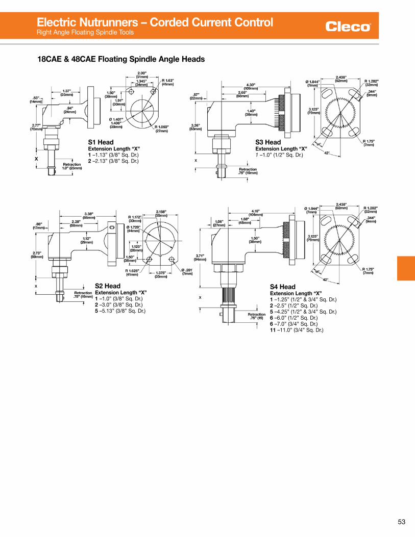
53
S3 Head Extension Length “X”1 –1 .0” (1/2” Sq . Dr .)
S4 Head Extension Length “X”1 –1 .25” (1/2” & 3/4” Sq . Dr .)2 –2 .5” (1/2” Sq . Dr .)5 –4 .25” (1/2” & 3/4” Sq . Dr .)6 –6 .0” (1/2” Sq . Dr .)6 –7 .0” (3/4” Sq . Dr .)11 –11 .0” (3/4” Sq . Dr .)
18CAE & 48CAE Floating Spindle Angle Heads
S1 Head Extension Length “X”1 –1 .13” (3/8” Sq . Dr .)2 –2 .13” (3/8” Sq . Dr .)
S2 Head Extension Length “X”1 –1 .0” (3/8” Sq . Dr .)2 –3 .0” (3/8” Sq . Dr .)5 –5 .13” (3/8” Sq . Dr .)
Electric Nutrunners – Corded Current ControlRight Angle Floating Spindle Tools

54
Crowfoot Torque Range FreeSpeed Weight* Length
Model Number15° Head 30° Head ft. lbs. Nm RPM lbs. kg in. mm
48CCE30C1 48CCE30C3 7 .7-22 .1 10 .5-30 860 5 .5 2 .3 20 .5 521
*Weights are without tool cable and reaction bar . General: All tools must be used with an approved ATG cable and controller .Standard Equipment: Air-LB Connector .
Extra Equipment: Std . tool cable 301866-XX, RA swivel cable 301903-XX, Inline swivel cable 301904-XX, Extension cable 301877-XX .Additional Accessories: See pages 58-61 for additional accessories .
To order individual sockets, use a “CS” prefix before the required socket . (i .e . CSEA01 for a, 1/4”, flush, thru hex socket .)
Crowfoot SeriesTorque Range Bolt Size 7 - 30 Nm M6 - M8 5 - 22 Ft. Lbs. #10 - 3/8”
■ Brushless precision■ Resolver control■ Memory intelligence
48CCE30C1
Electric Nutrunners – Corded Current ControlCrowfoot Tools
Max Output Torque<60 Nm, rounded up to the nearest 1 Nm .
Head TypeC1 - 15° CrowfootC3 - 30° Crowfoot
Motor48
Tool StyleC – Crowfoot
Current Control
Socket SizeEA – 1/4” MC – 9mmEC – 3/8 MD – 10mmEE – 1/2 ME – 11mm (7/16)EF – 9/16 MF – 12mmMA – 7mm MG – 13mmMB – 8mm (5/16) MH – 14mm MI – 15mm* *Fragile. Light duty apps.
Socket NomenclatureCrowfoot Tool Nomenclature
Output Style1 – Thru Hex
Connector E – Air-LB
Socket TypeCS – Crowfoot
Extension Length0 – Flush4 – 1/2”6 – 3/4”
48 C C E XX XX CS XX XX X
.61”(15.49)
.97”(24.63)
.75”(19)
3.00”(76.2)
30°
R.63”(16)
1.25”(31.75)
1.50”(38.1)
.25”(6.35)
C3 – 30° Head (Part No. 301960)Maximum Recommended Torque: 22 ft .lbs . (30 Nm)
15°
.61”(15.49)
1.09”(27.86)
.75”(19)
3.00”(76.2)
2.66”(67.56)
1.50”(38.1)
1.25”(31.75)
R.63”(16)
.25”(6.35)
C1 – 15° Head (Part No. 301959)Maximum Recommended Torque: 22 ft .lbs . (30 Nm)

55
Cleco mPro400GC-I Global Controller – Current Control
Weight Width Height Depth
Model Description Tool Compatibility lbs. kg in. mm in. mm in. mm
MPRO400GC-I Current Control Cleco 18-48 CXE Series* 32 .8 72 .3 10 .3 261 .62 14 .9 378 .46 12 .9 327 .66
*Note: 48 series tools require 230 VAC .
Current ControlmPro400GC-I Global Controller■ Single channel■ Economical■ Remote programming■ Local storage of 5,000 cycles■ LAN capable■ Input Voltage: 115/230VAC■ Connections: (1) Serial, (1) TM-COM, (1) Ethernet■ Inputs/Outputs: (8) 24V Inputs, (8) 24V Outputs
MPRO400GC-I

56
Isolation Transformer
Isolation Transformer544185PT
Incoming Power
115/230VAC(provided with
544185PT)
Matrix Tool Cable
542778-XMCleco 67 Series Tool
Air-Lb Cable(provided with 544185PT)
Power Cable(provided with 544185PT)
mPro400GC-IT Isolation Transformer
The purpose of the Isolation Transformer is to allow use of legacy Matrix connector tools (17/47, 18/48, and 67 Series) with the Global Controller and maintain safety and CE standards .
544185PT Isolation Transformer Applications
Controller
Tool Used
17/47E_XX (Matrix)
18/48E_XX (Matrix)
18/48E_EXX (Air-Lb)
67E_XX (Matrix)17/18C_EXX
(Air-Lb)
Fixtured Spindles
(DGD/EMT)
TME/TMEM No No Adapter Cable Required No NA NA
mPro400GC-P Yes Yes No Yes NA NA
mPro400GC-S Yes Yes No Yes NA NA
mPro400GC-M NA NA NA NA NA NA
mPro400GC-E Yes Yes No Yes NA NA
mPro400GC-I NA NA NA NA No NA
Air-Lb Connector Matrix Connector
■ 115/230 VAC Operation Selectable (Not auto sensing, switch selectable) . Factory default setting is 230 VAC .■ All connection cables included except Tool Cables . See below .
Tool CablesModel Number Swivel Length
Tool Extension Right Angle Inline Feet Meters
542778-1M* 542779-1M 544055-1M* 544056-1M* 3 1542778-2M* 542779-2M 544055-2M* 544056-2M* 6 2542778-3M 542779-3M 544055-3M 544056-3M 9 3542778-6M 542779-6M 544055-6M 544056-6M 19 .5 6542778-8M 542779-8M 544055-8M 544056-8M 26 8542778-10M 542779-10M 544055-10M 544056-10M 33 10542778-15M 542779-15M 544055-15M 544056-15M 49 15
542779-20M 66 20542779-25M 82 25542779-30M 96 30542779-40M 131 40
542778-50M 542779-50M 544055-50M 544056-50M 164 50
Maximum cable length 100M 115VAC/20M 230VAC.Overall minimum cable length 3M.*Must be used with 542779 extension cable.
Swivel Cable
Swivel cable rotates 330° to absorb constant
twisting and turning.

57
mProRemote & TM-COM Minimum System Requirements Operating System: Windows 2000, NT or XP Processor: Pentium Memory: 256MB Free Disk Space: 10MB per controller Other: MS Office 2000
Remote Programming SoftwareCleco’s remote programming software delivers ultimate control to the user, empowering them to control the production process remotely through programming that is easy to use and intuitive. Anything that can be programmed locally on the controller can also be performed from a remote location using the exact same screens.
Using this software to monitor, modify, and/or manage the production line will increase your efficiency and productivity. Centralized management of the tightening process assures quality products.
TM-COM (for GC-E/GC-I controllers) can communicate using eitheraRS232orTCP/IPconnection.mProRemote (for GC-M/GC-P controllers) utilizes a TCP/IP connection only.
TM-COM Network overview screen lists all mPro400GC-E and mPro400GC-I controllers connected to the network.
mProRemote for mPro400GC-M and mPro400GC-P controllers.
All menus in all controllers are accessible from the Navigator screen.
Remote Programming SoftwaremProRemote/TM-COM
Software
mProRemote Provided with each mPro400GC-M & mPro400GC-P TM-COM Provided with each mPro400GC-E & mPro400GC-I
Part Number Description

58
SoftwarePart No. Description
TMEB-COM-V2 .03 Remote Programming SoftwareIncluded with mPro400GC-E.
Accessories
935377 936400PT
Batteries
Part No. DescriptionWeight
lbs. kg
935377 26V Li-Ion 1 .1 0 .50936400PT 44V Li-Ion 1 .9 0 .85
Battery ChargerPart No. Description
936491PT 26V/44V charger
936491PT
Vmax TethersPart Number
Tool Extension961341-*** 961342-***
***Length: 030=3m, 060=6m, 080=8m, 100=10mNote: Maximum 20M length
961341-030
961342-030
Preventative Maintenance Diagnostics
■ USB to PC interface■ Displays discharge cycles, total and per cell voltage■ Better diagnostics■ Easy to troubleshoot
936492PT
Battery service interface allows cycles and cell voltages to be read via serial interface cable.
Pistol Dead HandlePart No. Description
301837 Reversible handle mount
301837
Tool Holder Extension CablesPart No. Description
935154 9’ (3m) extension cable935155 19 .5’ (6m) extension cable935157 33’ (10m) extension cable
Tool HoldersPart No. Description
935144 Pistol tool holder w/infrared interface935396 Pistol tool holder 935290 Angle tool holder w/infrared interface 935395 Angle tool holder935170 Infrared interface cable935998 70Nm RA, Crowfoot/Tubenut holder935999 70Nm RA, Crowfoot/Tubenut holder w/infrared interface
935290 935170
935144
541715-2
Tool Suspension BailPart No. Description
541715-2 Angle tool swivel bail
Model No.Weight Width Length Depth
lbs. kg in. mm in. mm in. mm
961350PT 6 .8 3 .1 9 .4 240 4 .7 120 5 .9 150
2M power cable included.
Vmax Power Module
2.4GHz to 5.0GHz Upgrade Kit
961323 / 593995
Part No. Description
543995 Access Point 2 .4GHz WLAN (US)961323 Access Point 2 .4GHz WLAN (EU)961253PT Access Point Dual Band 2 .4/5GHzRadio Range: 30-50 metersIEEE 802 .11a/b/g (depending on tool)Max . Tools: 10
WLAN Access Point – 2.4GHz/5.0GHz
mPro400GC Program & OS Software
Part No. Description
544163PT CompactFlash Module Programmed
Upgrades are available at your local ATG Application Center to upgrade the W and X series 2 .4GHz tools to a 5 .0GHz Y series tool .

59
Accessories
Part No. Description
544197PT System Bus Terminator544196-005 System Bus Cable - 0 .5M544196-020 System Bus Cable - 2M544196-050 System Bus Cable - 5M544196-200 System Bus Cable - 20M544196-500 System Bus Cable - 50MS133437 System Bus 16 I/O ExpanderS133436 System Bus 32 I/O ExpanderS133410 System Bus 4-Position Socket TrayS133411 System Bus 8-Position Socket TrayS133406 System Bus Control Box with BuzzerS133405 System Bus Stack Light without BuzzerS133420 System Bus Stack Light with Buzzer
System Bus Accessories
Part No. Description
543446-7 Ethernet Crossover Cable - 7ft .543445-7 Ethernet Patch Cable - 7ft .543445-50 Ethernet Patch Cable - 50ft .543445-100 Ethernet Patch Cable - 100ft .543490-10 Serial Null Modem Cable - 3M543444-8 Ethernet Switch - 8 Port543444-16 Ethernet Switch - 16 Port543444-24 Ethernet Switch - 24 Port
Network Accessories
S133410 Socket Tray
S133406 Control Box with Buzzer
S133420 Stack Light with Buzzer
544171PT Fieldbus
Devicenet
544173PT Fieldbus Profibus
544174PT Fieldbus Profinet
544172PT Fieldbus
Ethernet-IP
Part No. Description
544171PT Fieldbus Devicenet544172PT Fieldbus Ethernet-IP544173PT Fieldbus Profibus544174PT Fieldbus Profinet544211PT Fieldbus Modbus/TCP
Fieldbus Accessories
Discrete Input Accessories
Discrete Output Accessories
Torque Selector SwitchesPart No. Description542977-8 Torque Selector – 8 Position542977-16 Torque Selector – 16 Position542977-32 Torque Selector – 32 Position542977-64 Torque Selector – 64 Position 542977-8
AnnunciatorsPart No. Description542976-1 Annunciator – 1 Spindle542976-2 Annunciator – 2 Spindle542976-3 Annunciator – 3 Spindle542976-4 Annunciator – 4 Spindle542976-5 Annunciator – 5 Spindle542976-6 Annunciator – 6 Spindle
542976-1
Start/Stop SwitchesPart No. Description542972 Start Box542973 Stop Box542974 Start/Stop Box542975 Start/Stop/Reverse
542975
Part No. Description
544237-1M Accessory Input Cable - 1M544237-5M Accessory Input Cable - 5M544237-10M Accessory Input Cable - 10M544237-15M Accessory Input Cable - 15M542986-1M Accessory to Accessory Cable - 1M542986-5M Accessory to Accessory Cable - 5M542986-10M Accessory to Accessory Cable - 10M542986-15M Accessory to Accessory Cable - 15M544238-1M Accessory Output Cable - 1M544238-5M Accessory Output Cable - 5M544238-10M Accessory Output Cable - 10M544238-15M Accessory Output Cable - 15M
Accessory Cables
Socket Only TraysPart No. Description542978-4 Socket Tray – 4 Position542978-8 Socket Tray – 8 PositionNotes: Up to 16 linked 4 position trays maximum.Minimum socket O.D. 1”. Maximum O.D. 2.25”.See below for Socket Posts and Lockout Washers 542978-4
Bits & Socket Trays (Global Controller Only)
Part No. Description544241PT Tray – 4 Position with 10m cable544242PT Tray – 8 Position with 10m cable5970716 Replacement InsertsMaximum socket diameter 1.125”.
960645
597016
Socket PostsFor use with 542978-4 & 542978-8 socket trays.
Part No. Socket Post Size Part No. Socket Post Size99249181 .550/ .540 99249158 .687/ .67799249169 1 .062/1 .052 99249157 .875/ .86599249165 .590/ .580 99249156 1 .000/ .99099249164 .945/ .935 99249148 1 .125/1 .11599249163 .827/ .817 99249147 .938/ .92899249162 .709/ .699 99249104 .750/ .74099249161 .625/ .615 99249103 .669/ .65999249160 .437/ .432 99249102 .562/ .55299249159 .812/ .802 99249101 .500/ .490Note: Select socket post size within tolerance of socket used.Choose largest socket post size (diameter) that will accept the hex size of the intended socket.
Part Number Note99248150 Vacant position lockout washer
Required for unused positions on the 542978-4 & 542978-8 socket tray.
Lockout WasherFor use with 542978-4 & 542978-8 socket trays.

60
Accessories
301877-XM961249-XXX
Extension
301866-XXX301903-XXX301904-XXX
Tool
AirLB18/48EAE
Tool CablesModel Number Swivel Length
Tool Extension Right Angle Inline Feet Meters
301866-1M* 301877-1M 301903-1M* 301904-1M* 3 1301866-2M* 301877-2M 301903-2M* 301904-2M* 6 2301866-3M 301877-3M 301903-3M 301904-3M 9 3301866-6M 301877-6M 301903-6M 301904-6M 19 .5 6301866-8M 301877-8M 301903-8M 301904-8M 26 8301866-10M 301877-10M 301903-10M 301904-10M 33 10301866-15M 301877-15M 301903-15M 301904-15M 49 15
301877-20M 66 20Maximum tool to controller cable length 20M.Overall minimum cable length 3M.*Must be used with 301877 extension cable.
Swivel Cable
Swivel cable rotates 330° to absorb constant
twisting and turning.
Lever Extension KitsDescription Part No.
Lever Extension Kit (non-swivel) 541757Lever Extension Kit (swivel) 543414Note: Models for standard tool cable (non-swivel) and swivel cable.
Suspension BailDescription Part No.
Tool suspension bail 1110909
Medium to Hard TorqueBelleville Washer Test Fixture is clamped in a vise and used to test tools (10 In . Lbs . – 100 Ft . Lbs ., 1 .13Nm – 135 .6Nm) . Washers can be rearranged to simulate “hard” or “soft” joints .
Test Fixture
536185
Part Number
3/4”100 Ft .Lbs .
Max . 1/2” Hex25 Ft .Lbs .
Max .
Tool & Cable TesterPart No. Description
961024 Tool & cable testertool memory programming
542991 Tool & cable testerNote: Adapter cable required for Air-Lb tools. Contact Tech Service.
Joint SimulatorJoint simulators are most frequently used to certify the repeatability of nutrunners before being installed on a production line and are also an excellent means of testing nutrunners following repair .
The Joint Simulator can simulate and test the torque output of nutrunners on both hard and soft joints . Each Joint Simulator is supplied with a quantity of spring washers which are used to test tool accuracy . Torque per revolution is varied by stacking the spring washers in different combinations .
Electronic torque testing is accomplished by attaching an external rotary transducer between the tool’s square drive and the socket .
■ Easy access, load, set-up and maintenance.■ Heavy-duty and economical.■ Adjustable torque reaction bracket can accommodate virtually any tool.■ For use with reversible/ non-reversible tools.
Part No. Torque Range Width Height LengthFt. Lbs. Nm in. mm in. mm in. mm
550006 12-220 15-300 10 .4 264 16 406 26 .5 667

61
Accessories
Ø .328 ± .006/.000CSK Ø .346 x 60°4 Places
Ø 2.374±.001-X-1.800
.375
3.15
2.50
2.46
.735
543230Ø .328 ± .006/.000V Ø .346 x 60°Both Sides2 Places
3.001.750 .600
1.9852.545
543235 543232
Ø .328 ± .006/.000V Ø .346 x 60°Both Sides2 Places
3.001.750 .600
1.9852.545
543235
Tool Type Model Number Cover Swivel Bail Mounting Plate Extension
Right Angle 17/18EA…AL2 205832 541715-2 ------ ------17/18EA…AM3 205834 541715-2 ------ ------47EA…AM3/4 543070 541715-2 543235 54242847/48EA…AH4 543070 541715 543230 53583347/48EA135MH4 543071 541715 543230 53583347/48EA…AX6 205838 541715 543232 ------67EA…AL6 205838 35007004 49097101 (included with tool) 4831603367EA…AM6 ------ 48A17006 45017152 (included with tool) ------
Flush Socket 17/18EA…F1… ------ 541715-2 57217101 (requires 57218103 screw) ------47/48EA…F2… ------ 541715-2 43287131 ------47/48EA…F3… ------ 541715-2 49097101(requires 49098103 locknut) ------47/48EA…F4… 205838 541715 49097101(requires 49098103 locknut) 48316033
Hold-N-Drive 47/48EA …H…over 100NM 205838 541715 49097101(requires 49098103 locknut) 4831603347/48EA …H…under 100NM 205838 541715-2 49097101(requires 49098103 locknut) 48316033
543231
49087108
Inline Tools Mounting Plates

62
Accessories
System Component ConnectivityThis diagram is intended to show how various components connect in a system, not necessarily the exact components required to create a particular system.*These items do not apply to mPro400GC-E and mPro400GC-I
mPro400GC-P mPro400GC-S
542977-8
935290
301877-XM961249-XXX
Extension
301877-XM961249-XXX
Extension
301866-XXX301903-XXX301904-XXX
Tool
301866-XXX301903-XXX301904-XXX
Tool
18/48EAE
18/48EAE
S133420 Stack Light with Buzzer
Access Point*
Discrete I/O Accessory:Torque Selector Box
Accessory Input Cable 544237-XM(Connects to green Phoenix connectors)
Ethernet Crossover
Cable supplied with Access
Point(Connects to
Ethernet Connector)
IRDA device* needed for initial setup.(Connects to Serial connector)
System Bus Cable* 544196-XXX(Connects to System Bus connector)
Tool Cable connects to Tool connector
Tool Cable connects to Tool connector
System Bus I/O Accessory*
Terminator Plug*
544197PT

63
R1 MAX
R1 MIN
R2 MINH MIN
H MAX
R2 MAX
Balance Arm Operating Envelope
MODEL R1 MAX R1 MIN R2 MAX R2 MIN H MAX H MIN
in. mm in. mm in. mm in. mm in. mm in. mm
SBA-12 24 610 2 51 18 457 8 203 15 381 6 152
SBA-18 30 762 6 152 20 508 7 178 15 381 0 0
PBA-12 26 660 3 76 20 508 7 178 17 432 8 203
PBA-18 32 813 8 203 22 559 6 152 17 432 2 51
Single Arms Parallel Arms Dimensions
Model No. Code No. Model No. Code No.A B C D
in. mm in. mm in. mm in. mm
Air Cylinder ModelsCSBA18 520160 CPBA-18 520170 12 305 18 457 18 457 - -CSBA-24 520200 12 305 24 610 18 457 - -CSBA-30 520201 CPBA-30 520203 12 305 30 762 18 457 - -CSBA-12-AH 520165 CPBA-12-AH 520178 12 305 12 305 - - 30 762CSBA-18-AH 520162 CPBA-18-AH 520172 12 305 18 457 - - 30 762CSBA-30-AH 520167 CPBA-30-AH 520215 12 305 30 762 - - 30 762
CPBA-30-WM 520207 12 305 30 762 - - - -
Spring ModelsSBA-12 520001 PBA-12 520007 12 305 12 305 18 457 - -SBA-18 520004 PBA-18 520010 12 305 18 457 18 457 - -
PBA-24 520045 12 305 24 610 18 457 - -SBA-12-AH 520003 PBA-12-AH 520009 12 305 12 305 - - 30 762SBA-18-AH 520006 PBA-18-AH 520012 12 305 18 457 - - 30 762SBA-24-AH 520110 PBA-24-AH 520047 12 305 24 610 - - 30 762SBA-30-AH 520044 PBA-30-AH 520050 12 305 30 762 - - 30 762
PBA-18-18-AH 520036 18 457 18 305 - - 30 762PBA-12-WM 520008 12 305 12 305 - - - -
SBA-30-WM 520043 12 305 30 762 - - - -
AH = Adjustable Height WM = Wall MountedTool weight capacity: 10 lbs . (4 .6 kg) Air Cylinder models 5 lbs . (2 .3 kg) Spring modelsTorque capacity: 10 ft . lbs . (13 .5 Nm)
Standard Equipment: Operating Instructions and Service Manual . Regulator for Air Cylinders .
Threaded Nipples for CSBA Models 1/4 NPT Hex Nipple: 204032 1/4 NPT x 1/8 NPT Hex Reducer Nipple: 204137
Optional Equipment: Additional accessories: See page 64 .
■ Ball bearing construction
■ Supports tools weighing up to 5 lbs . (spring models) or up to 10 lbs . (air cylinder models) .
■ Post, wall, or adjustable height post mounting
■ Single or parallel arms
TOOLS NOT INCLUDED
Air CylinderParallel Arm CPBA-18-AH
SpringParallel Arm PBA-18
Mount- – PostAH – Adjustable HeightWM – Wall Mount
Series
CS – Air cylinder, single armS – Spring, single armCP – Air cylinder, parallel armP – Spring, parallel arm
Tool Type
BA – Balance Arm
XX BA - XX - XX - XX
Arm Extension12” 24”18” 30”(12” unless specified)
Adjustable Arm Extension
12” 24”18” 30”
Electric Nutrunner AccessoriesBalance Arms

64
AccessoriesBalance Arms
BM-13AZBL-6A
200427PL-12A
Ergonomic Tool BalancersCapacity: 0.5 – 20.5 kg 1.0 – 45 Lbs■ External tension Adjustment■ 360° Swivel■ Retracting In-Line Cable
Model No. Lock FeatureCapacity “A” “B” “C” Weight
lbs. kg in. mm in. mm in. mm lbs. kg
Light Duty – 4.6 ft. (1.4m) Cable TravelPL-12A – 12 .0-1 .0 5 .5-0 .5 6 .8 171 5 .1 130 2 .3 58 – –
Light Duty – 5.0 ft. (1.5m) Cable Travel200427 – 2 .0-0 .9-0 10 .9 277 4 .4 112 1 .6 41 1 .3 0 .6200428 – 4 .0-2 .0 1 .8- .9 10 .9 277 4 .4 112 1 .6 41 1 .3 0 .6200429 – 5 .0-3 .0 2 .3-1 .4 10 .9 277 4 .4 112 1 .6 41 1 .3 0 .6
Light Duty – 5.2 ft. (1.6m) Cable TravelBL-2A – 2 .0-1 .0 0 .9-0 .5 10 .4 263 4 .0 102 2 .2 56 1 .1 0 .5BL-4A – 4 .0-20 1 .8-0 .9 10 .4 263 4 .0 102 2 .2 56 1 .1 0 .5
Light Duty – 6.7 ft. (2.0m) Cable TravelBL-6A – 6 .0-4 .0 2 .7-1 .8 12 .9 327 5 .5 140 3 .1 79 3 .3 1 .5BLL-6A Ratchet 6 .0-4 .0 2 .7-1 .8 12 .9 327 5 .5 140 3 .1 79 3 .3 1 .5BL-8A – 8 .0-6 .0 3 .6-2 .7 12 .9 327 5 .5 140 3 .1 79 3 .3 1 .5BLL-8A Ratchet 8 .0-6 .0 3 .6-2 .7 12 .9 327 5 .5 140 3 .1 79 3 .3 1 .5
Medium Duty – 6.6ft. (2.0m) Cable TravelBM-13A Automatic 13-9 .0 5 .9-4 .1 13 .8 350 6 .9 175 4 .5 114 9 .0 4 .1BML-13A Automatic/Ratchet 13-9 .0 5 .9-4 .1 13 .8 350 6 .9 175 4 .5 114 9 .0 4 .1BM-18A Automatic 18-13 8 .2-5 .9 13 .8 350 6 .9 175 4 .5 114 9 .0 4 .1
Medium Duty – 6.0ft. (1.8m) Cable TravelBM-25A Automatic 25-18 11 .4-8 .2 20 .7 527 7 .8 197 6 .6 169 19 8 .6BM-35A Automatic 35-25 15 .9-11 .4 20 .7 527 7 .8 197 6 .6 169 19 8 .6BM-45A Automatic 45-35 20 .5-15 .9 20 .7 527 7 .8 197 6 .6 169 19 8 .6
*4 .9 ft . cable travel
B
A
C
+
_
+– A
B C
1/2” Dia.(12.7mm)
C
B
A
Light Duty (PL Series)
Light Duty (BL Series)Medium & Heavy Duty
B
A
C
+
_
+– A
B C
1/2” Dia.(12.7mm)
C
B
A
Light Duty (PL Series)
Light Duty (BL Series)Medium & Heavy Duty
204120
204119
204122
204014
Conversion Kits for Cleco Screwdriver Balance Arms
To Convert Balance ArmsPart No.
From ToSBA-12 PBA-12* 521041SBA-18 PBA-18* 521042Spring Cylinder 201606SBA or PBAStandard Duty
SBA or PBAHeavy Duty** 521060
*Conversion kits for -24 and -30 models are available upon request .**Has four springs to support heavier tools or longer arms .
Articulating Arm ExtensionsPart Number Length (inches)
204014 12204122 18204119 24204120 30
301129
301128
301130
301131
Tool HoldersPart Number Description
301128 18/48 Pistol-Horiz . Tool Holder301129 18/48 Pistol- Vert . Tool Holder301130 18/48 Inline-Horiz . Tool Holder301131 18/48 Inline-Vert . Tool Holder

65
Your Single Source For Custom Automated SystemsAutomated Systems provides custom solutions for the automated fastening of threaded joints.
Our global customers span the entire vehicle assembly market, including passenger cars and trucks, power train assembly, off-road vehicles, and agricultural machines. We support machine tool builders in the vehicle and industrial markets with custom fastening system designs based on proven fastening product building modules.
Over many decades, Automated Systems has been providing custom solutions for training, service, and support. From single handheld nutrunners to multiple spindle machines, our custom designed systems are used around the world in an interesting variety of applications.
We have a full support staff of Sales Engineers, Mechanical Engineers, Controls Engineers, Project Managers, Field Service Engineers and In house Service Engineers waiting to serve you.
Custom Automated SolutionsThe custom designed equipment Automated Systems creates can be configured in either vertical or horizontal orientations depending on the application and customer requirements
Automated Systems
Shown below is a semi-automated water-pump subassembly fastening station. This station design includes a safety light curtain and a 4 spindle fixtured electric tool.
An automatic station on an engine assembly line uses two opposing electric power heads, each having 8 spindles, and a center power head of 6 spindles.
Shown above is a manually operated system with a 24 spindle powerhead that has the capability to manually orientate the spindles radially.
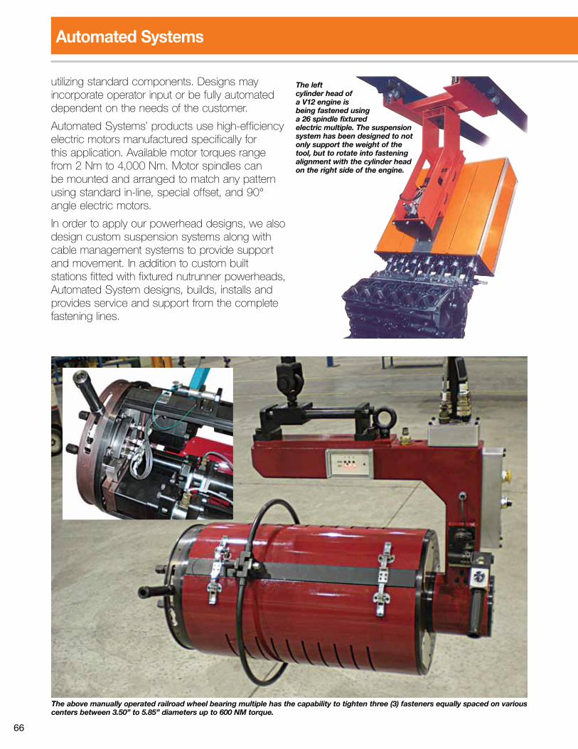
66
Automated Systems
The left cylinder head of a V12 engine is being fastened using a 26 spindle fixtured electric multiple. The suspension system has been designed to not only support the weight of the tool, but to rotate into fastening alignment with the cylinder head on the right side of the engine.
utilizing standard components. Designs may incorporate operator input or be fully automated dependent on the needs of the customer.
Automated Systems’ products use high-efficiency electric motors manufactured specifically for this application. Available motor torques range from2Nmto4,000Nm.Motorspindlescanbe mounted and arranged to match any pattern using standard in-line, special offset, and 90° angle electric motors.
In order to apply our powerhead designs, we also design custom suspension systems along with cable management systems to provide support and movement. In addition to custom built stations fitted with fixtured nutrunner powerheads, Automated System designs, builds, installs and provides service and support from the complete fastening lines.
The above manually operated railroad wheel bearing multiple has the capability to tighten three (3) fasteners equally spaced on various centers between 3.50” to 5.85” diameters up to 600 NM torque.

67
Articulating Support ArmsThe basic underlying reason for the use of an articulating arm is to improve productivity through applied ergonomics. A manufacturer cannot ignore the pressure to improve productivity of employees because of the impact productivity has on the bottom line.
Automated Systems offers an articulating arm that can be designed for your suspension application. Articulating arms are also called tool balance arms. Automated Systems’ HDA series articulating arms are sized and designed to accommodate different size tools and mounting brackets required for specific applications. The arm can be suspended from an overhead rail,
structural column, ceiling mounted or post. The tool is typically mounted on the end of the arm.
Uses for Articulating Arms■ Stop or AGV stations■ Slow moving conveyor arms■ Work cells ■ Side or overhead tool position work
Typical Articulating Arm Features■ Single or parallel arms■ Arm leveling base■ Boom■ Air balancing cylinder■ Mounting end■ Lift arm
Optional Features■ Pneumatic or electric disc brake
Cable ManagementAutomated Systems can provide you with assistance ranging from concept to installation of an efficient cable management solution. Automated Systems equipment uses cables in conjunction with hand held tools, fixtured hand tools or when nutrunners are provided for incorporation into automated systems.
Cables need to be protected throughout their routing. We protect the cables from machine movement, equipment, chaffing, sharp objects, vibration, heat and liquid.
We have a full support staff of Sales Engineers, Mechanical Engineers, Controls Engineers, Project Managers, Field Service Engineers and In-house Service Engineers waiting to serve you.
UII
DET
180
215
UII
DET
180
215
To Cable Tray and PanelCable Organizer
Fixed Trolley
Runway Rail
Support Steel I-Beam
Restraint Cable
Tie Bar to First Trolley
Tube In Tube Extensionfor adjustment
Cylinder
Powerhead with start handle
Cross Rail withDouble Trolley Bridge
Cross Rail Trolley
Plant Air
18”-36”
ToolController
8’-10’
18”-36”
18”-36”Travel
OptionalTool Swivel
Apex Tool GroupHDA Series Articulating Balance Arms0-450 Ft./Lbs. Torque Capacity
Optional Remote Start Handle Available
Consult factory for special configurations not shown.
Standard Post.Optional mounting configurationsavailable.
Automated Systems Articulating Arms & Cable Management

68
Automated Systems Torque Handling System
Modular Handling Systems for Handheld Nutrunners & Tightening Spindles
Advantages■ High flexibility/adaptability to your fastening application■ Compact and coordinated system■ Effortless handling■ Can handle DGD and EMT spindles as well as Cleco DC nutrunners■ Modular components means short delivery times
Repair bay operator is using a two spindle fixtured tool to fasten components of a wheel hub assembly.
Standard Features■ Dual start/stop handles■ Lightweight aluminum covers & frame■ E-stop■ Ease of service . Easy spindle removal for maintenance or calibration■ Remote spindle indicator lights
■ 2 inch retractable spindle travel■ On-powerhead calibration■ Extended support tubes
Optional Features■ Powerhead kick-off from wheel■ Remote digital display (MMI)
■ Headlights■ Adjustable spindle centers■ Auto spindle retraction for multi-product assembly lines■ Fabricated steel suspension arm■ Part detection
Horizontal Rear Trunion Mount(Wheelnut Application)
Angled Down Swivel Open Frame(Rocker Application)
Horizontal Front Trunion Mount(Wheelnut Application)
Vertical Down Enclosure(U-bolt Application)
Horizontal Enclosure(Exhaust Manifold Application)
Vertical Up Enclosure(U-bolt Application)
Typical Torque Handling System Configurations

69
Wheelnut Fastening
Automated Systems is the recognized leader in the design and manufacture of multiple spindle wheel-nut assembly systems. We are known across the globe for excellence of innovative engineering design, support, and quality award winning service.
Decades of expertise in the design and manu-facturing of multiple spindle fixtured and portable assembly systems have identified Automated Systems as an experienced, innovative supplier capable of creating custom solutions matched to unique customer assembly requirements.
Automated Systems makes use of standard sys-tem building block components which are used to blend a custom system from a complete line of DC electric spindles, fastening controllers and an extensive listing of twenty-four different fastening strategies which not only include the usual Torque Control,AngleControlandYield,butalsoincludesthe unusual Pulse Torque Recovery makeup torque fastening strategy awarded US Patent number5,094,301.
Medium Duty Wheelnut Tool For Passenger Vehicles requiring Medium Torque, High Volume
• 100 Nm to 500 Nm
Automated Systems supplies custom Wheelnut multiple designs using standard major com-ponents with proven track records for reliability, lifetime performance, millions of cycles capability and ergonomic solutions which support operator safety, comfort and efficiency.
Heavy Duty Wheelnut Tool For Trucks requiring High Torque, Low Volume
• 700 Nm to 1200 Nm
Automated Systems Wheelnut multiples use high-efficiency electric motors manufactured specifically for this application. Available motor torques range from700Nmto1200Nm.Motorspindlescanbemounted and arranged to match any bolt circle pattern, using standard in-line motors with or without offset gearing.
Automated SystemsWheelnut Fastening

70
Automated SystemsWheelnut Fastening
Adjustable Wheel Stud Centers
When several similar wheels need to be assem-bled and the economics of separate powerheads dictates a single powerhead, Automated Systems has the answer! Adjustable stud centers. The posi-tion of the studs can be controlled by an operator manual switch, or auto detection.
Budd Double Wheels
When it comes to fastening inner and outer wheel lug nuts including Budd style stud/nut adapters, a wheelnut powerhead requires long retractable spindles which are designed to prevent side loading. Automated Systems has the know-how, and the products to supply wheelnut multiples for double wheel truck applications. Our wheel equip-ment is more rugged than the trucks it assembles.
Suspension Sys-tem
A properly designed suspension system can not only support the tool and return it to a home position, it can also provide a zero grav-ity lift and hold. The total weight of the tool is controlled by the operator with very little pressure required to move the tool up or down.
Local Operator Display (Operator Interface)
Each powerhead displays a red, green, and yellow LED on a per spindle basis. The LED display indicates the status of the last tighteningasNOK,OKandLowTorqueorAngle. An optional local operator interface display can be used to display output, and accept touch screen switch inputs.
Some of the uses of a local operator display include:• Application selection• Tool home position jog• Overall fastening status in green or red• Part graphics• Fastening values for torque and angle• Functional push-button inputs & display outputs
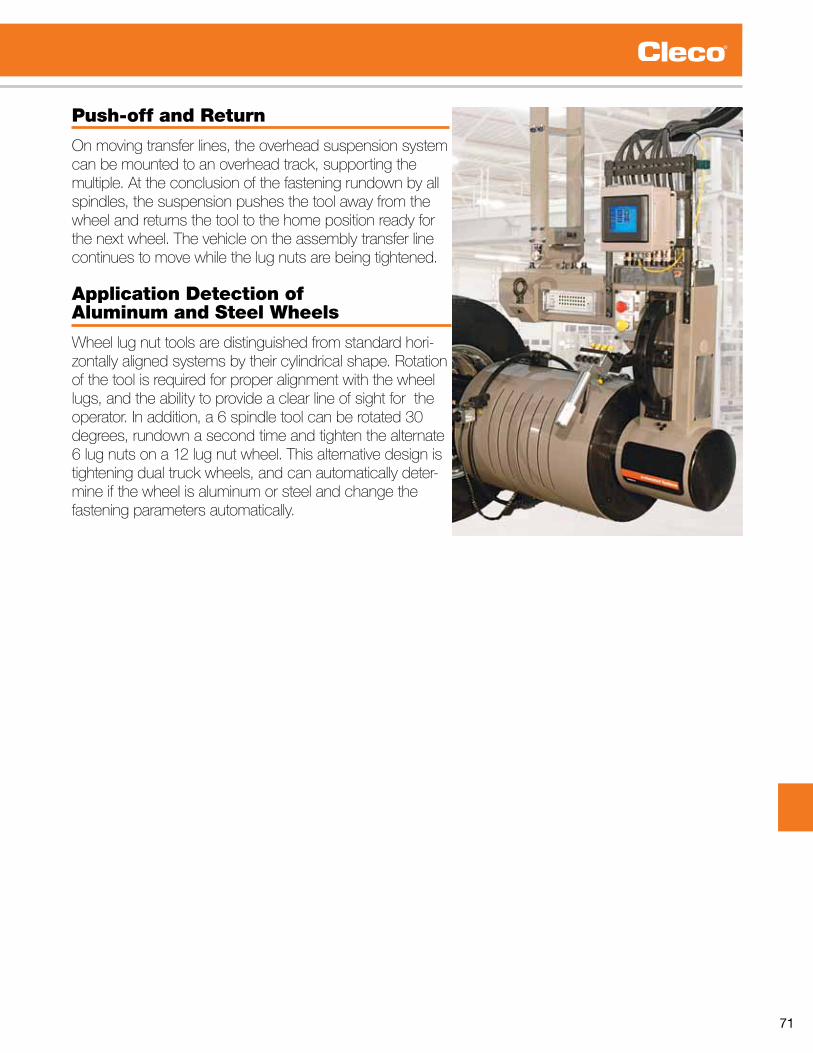
71
Push-off and Return
On moving transfer lines, the overhead suspension system can be mounted to an overhead track, supporting the multiple. At the conclusion of the fastening rundown by all spindles, the suspension pushes the tool away from the wheel and returns the tool to the home position ready for the next wheel. The vehicle on the assembly transfer line continues to move while the lug nuts are being tightened.
Application Detection of Aluminum and Steel Wheels
Wheel lug nut tools are distinguished from standard hori-zontally aligned systems by their cylindrical shape. Rotation of the tool is required for proper alignment with the wheel lugs, and the ability to provide a clear line of sight for the operator.Inaddition,a6spindletoolcanberotated30degrees, rundown a second time and tighten the alternate 6lugnutsona12lugnutwheel.Thisalternativedesignistightening dual truck wheels, and can automatically deter-mine if the wheel is aluminum or steel and change the fastening parameters automatically.

72
Productivity That Drives Cost SavingsIntelligent Spindles
Introduced in 2005, DGD Intelligent Spindles were the first fixtured nutrunners that offered onboard servo and modular construction. Today, these third generation nutrunners are based on over 50 years of proven success of our conventional spindles.
DGD Intelligent Spindles combine high speed, exceptional up time availability, and unprecedented accuracy and durability in a compact design that requires substantially less cabling than traditional nutrunners. The result is productivity gains at a lower cost,
withupto30%savingsoninitialpurchaseprice.DGDIntelligent Spindles also offer easy integration with Cleco electric tool products, including the new Cleco Global Controller.
Up To 170% FasterWithsealed,long-life,maintenance-free380VDC motors, DGD Intelligent Spindles are faster than a conventional spindle at most every torque level.
Compact On-Board Intelligence The on-board servo module is proven technology that has been tested to:•Shock&Vibration:3dimensionat13G• Temperature : 45° C• MTBF of 7 million cycles
Durability & AccuracyThe BTSE nutrunners are certified to the highest standard of accuracy and durability.• ISO certified to ±2%accuracy• 1 million duty cycles maintenance free•3millioncycleguaran-tee@80%ofcapability
Reduced Field CablesDGD Intelligent Spindles provide a solution for the number-one cause of shut-down … cable failure … by substantially reducing the number of cables needed. Where DGD conventional spindles each needaseparatecable,upto16IntelligentSpindlescan be run from a single field cable by cascading cables between spindles.
Field Cable
DGD Speed ComparisonTorque
(Nm)
DGDConventional
Spindle
DGD Intelligent
Spindle
DGDRPM
Advantage
10 1222 1921 57%
50 329 890 170%
100 329 890 170%
150 219 502 137%
200 220 502 48%

73
Productivity That Drives Cost Savings
Power Distribution
System Transformer
Acquisition & Installation Costs plus Floor Space Are All Reduced
System Simplicity
Cost effective DGD Intelligent System
Older and more expensive DGD Conventional System
Savings with a DGD 10 Spindle Intelligent Spindle System
vs . DGD Conventional SystemIn The Following Areas
Festooning Hardware (including installation)
Installation Labor
System Field Cables
Replacement Spare Parts & Cables
Trouble Shooting Time
System Availability
Incredible $avings!
DGD Conventional Spindle System Solution
DGD Intelligent Spindle System Solution
DGD 10 Spindle Requirements
Conventional Intelligent
10 Controllers 1
10 Field Cables 1
10 Power Interface Points 1
5 hrs . Cable Festooning Time 1 hr.
5 hrs . Controller Installation Time 1 hr.
5 hrs . Startup/Debug Time
3 hrs.
6 sq .ft .
Required Floor Space
3.5 sq.ft.
NoAbility to add
additional tools to existing controller
YesATG $avings Time &
Material
Tools, Cables & Controller $Installation $$$Parts (cables & controllers) $
Total System $avings $$
✔✔✔✔✔
✔

74
How To Build A Fixtured DC Tool System
Building a Fixtured DC Tool System is as simple as 1, 2, 3!
1. Choose a common system to the right. 2. Select the correct components below. 3. Order your System!
System Control Package -Controller, Power Transformer, Power Distribution Box, Arcnet Cable, and Stand (Page 80)
mPro400GCM PDBCPSXX - Select model from catalog. 1 1
Intelligent Fixtured Spindle (Page 79) Select from catalog. 1 2
Floating Spindle Adapters (Page 78) Select from catalog. 1 2
Field Cables - Intelligent Spindle (Page 77) Select cable with desired connector from catalog. 1 1
Jumper/Extension Cables - Intelligent Spindle (Page 77) Select cable with desired connector from catalog. 1 1
System Bus Terminator at spindle - Intelligent Spindle (Page 77) 961127 1 1
Controller - Conventional Spindle (Page 40)
mPro400GC-P-12 (Primary Size 12) 1 1mPro400GC-S-12 (Secondary Size 12) 1mPro400GC-P-34 (Primary, Size 34) 1 1mPro400GC-S-34 (Secondary, Size 34) 1
Conventional Fixtured Spindle (Pages 81-84) Select from catalog. 1 1 2 2
Floating Spindle Adapters (Page 85) Select from catalog. 1 1 2 2
Field Cables - Conventional Spindle (Page 77) Select from catalog. 1 1 2 2
Extension Cables - Conventional Spindle (Page 77) Select from catalog. 1 1 2 2
System Bus Cable - (Page 77)Select from catalog.*(Included in the System Control Package)
1 1 * *
System Bus Terminator at Controller - Conventional Spindle (Page 77) 544197PT 1 1

75
Add or delete components as required.
System Control Package -Controller, Power Transformer, Power Distribution Box, Arcnet Cable, and Stand (Page 80)
mPro400GCM PDBCPSXX - Select model from catalog. 1 1
Intelligent Fixtured Spindle (Page 79) Select from catalog. 1 2
Floating Spindle Adapters (Page 78) Select from catalog. 1 2
Field Cables - Intelligent Spindle (Page 77) Select cable with desired connector from catalog. 1 1
Jumper/Extension Cables - Intelligent Spindle (Page 77) Select cable with desired connector from catalog. 1 1
System Bus Terminator at spindle - Intelligent Spindle (Page 77) 961127 1 1
Controller - Conventional Spindle (Page 40)
mPro400GC-P-12 (Primary Size 12) 1 1mPro400GC-S-12 (Secondary Size 12) 1mPro400GC-P-34 (Primary, Size 34) 1 1mPro400GC-S-34 (Secondary, Size 34) 1
Conventional Fixtured Spindle (Pages 81-84) Select from catalog. 1 1 2 2
Floating Spindle Adapters (Page 85) Select from catalog. 1 1 2 2
Field Cables - Conventional Spindle (Page 77) Select from catalog. 1 1 2 2
Extension Cables - Conventional Spindle (Page 77) Select from catalog. 1 1 2 2
System Bus Cable - (Page 77)Select from catalog.*(Included in the System Control Package)
1 1 * *
System Bus Terminator at Controller - Conventional Spindle (Page 77) 544197PT 1 1
Conventional Single Spindle (Size 1, 2)
Conventional Single Spindle (Size 3, 4)
Conventional Two Spindle (Size 1, 2)
Conventional Two Spindle (Size 3, 4)
>2 Convent. Spindles - Consult Application Center
Single Intelligent Spindle
Two Intelligent Spindles
>2 Intelligent Spindles - Consult Application CenterModel/Part Number

76
Intelligent Spindles
The Most Flexible, Cost-Effective Systems Controller ... Ever
Description Tool Compatibility Model
Primary Cleco 18-48 Series, LiveWire, Intelligent Spindle* MPRO400GC-PMaster LiveWire, Intelligent Spindle* MPRO400GC-MPanel Mount LiveWire, Intelligent Spindle MPRO400GC-MPM* Requires quote to accommodate hardware configurations.
Cleco Global Controllers for Intelligent Spindles Master/Primary Unit Panel Mount
DGD Intelligent Spindles can be used in conjunction with any Cleco DC electric tool combination – cordless LiveWire or corded handheld – and with
the mPro400GC Global Controller for even greater efficiencies.
Versatility To Work With Many Tool Configurations
One controller manages up to 32 tools simultaneously in varying combinations.
CustomerDataServer
Line Control System
RemoteProgramming/Monitoring
Error Proofing(CEC, Synatec and more)
Supports Open Protocol(PinPoint, ToolsNet and more)
Plant/LocalAccess Point
RemoteHMI
Cordless Handheld Tools
Up To 10 Tools/Controller
Fiel
dbus
/ I/
O
Eth
erne
t TC
P/I
P
Fixtured Intelligent Spindles
Corded Handheld Tool
WirelessTorque Wrench
Modular Tightening System
Power Dist.
System

77
The Most Flexible, Cost-Effective Systems Controller ... EverConnection & Extension Cables For Intelligent SpindlesJumper Cables, Straight Connector
HighFlex Quality■ For fixed or flexible routing with heavy-duty requirements in applications with cable drag chain or standard robot applications
SuperHighFlex Quality■ For robot and all high mobility applications (high durability) with complex motion-sequences■ Available on request
System Cables for Intelligent SpindlePrimary Field Cables
Description Length* (m) Order No.
Highflex Type AStraight connector on both sides
0,5 961104-0051 961104-0102 961104-0203 961104-0304 961104-0405 961104-0506 961104-0607 961104-0708 961104-0809 961104-09010 961104-10015 961104-15020 961104-20030 961104-30040 961104-40050 961104-500
*The cable lengths are specified in decimeters at the end of the order number
Jumper Cables
Description Length* (m) Order No.
Highflex Type D (Jumper) straight connector on both sidesmoulded connector housing
0 .5 961104-0051 .0 961104-0102 .0 961104-020
Highflex Type E (Jumper) 90° connector on both sides rotatable cable glands
0 .5 961299-0051 .0 961299-0102 .0 961299-020
*The cable lengths are specified in decimeters at the end of the order number.Other cable length on request.
Description Length* (m) Order No.
System Bus Cable 0 .5 544196-005System Bus Cable 2 .0 544196-020System Bus Cable 5 .0 544196-050System Bus Cable 20 .0 544196-200System Bus Cable 50 .0 544196-500
System Bus Cables
*The cable lengths are specified in decimeters at the end of the order number
mPro400GC-MBus-Terminator
961127
System Bus Cable
Power Dist.
System
Jumper Cables between nutrunners (straight connector)
Primary Field Cable, direct connection between nutrunner and fastening control (straight connector)
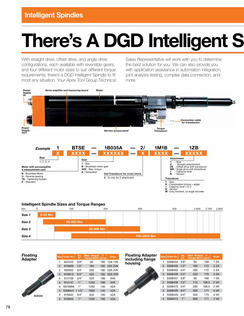
78
Intelligent Spindles
With straight drive, offset drive, and angle drive configurations, each available with reversible gears, and four different motor sizes to suit different torque requirements, there’s a DGD Intelligent Spindle to fit mostanysituation.YourApexToolGroupTechnical
Sales Representative will work with you to determine the best solution for you. We can also provide you with application assistance in automation integration, joint analysis testing, complex data connection, and more.
There’s A DGD Intelligent Spindle For Your Application
Power Supply OUT
Power Supply IN
Servo amplifier and measuring board
Service access panel
Connection cable for transducers
Motor
Torque Transducer
Intelligent Spindle Sizes and Torque Ranges
Size 1
Size 2
Size 3
Size 4
Nm 0 100 200 300 400 . . . 2 .600 2 .700 2 .800
2-53 Nm
25-200 Nm
50-300 Nm
100-2800 Nm
Motor with servoamplifier & measurement card
B - Brushless MotorU - Reverse gearingTS - Tightening SystemE - Standard
Example
Size
1, 2, 3, 4Gear
1 - SizeB - Brushless motor gearXXX - Max . torqueA - Generation
2nd Transducer for cross check
2 - 2x only for Z attachment
Attachment1 - SizeZ - Straight attachementVK - Offset drive with transducerWK - Angle drive with transducer1 - Capacity levelB - Version
Transducer 1 - SizeK - Combination torque + angle1 - Capacity level 1 or 2B - VersionM - Only moment, no angle encoder
1 BTSE — 1B035A — 2/ 1M1B — 1ZBX XXXX — XXXXXX — X XXXX — XXXXX
Floating Adapter including flange housing
Size Order No. Sq. Dr.
Max. Torque Range (Nm)
X (mm) Drive
1 S308434 3/8” 60 168 1 ZA
2 S308435 1/2” 160 172 2 ZA
2 S308450 3/4” 200 172 2 ZA
3 S308436 3/4” 520 176 3 ZA
1 S308437 3/8” 60 168 1 VK
2 S308438 1/2” 110 166,5 2 VK
2 S308475 3/4” 200 166,5 2 VK
3 S308439 3/4” 300 171 3 VK
4 S308440 3/4” 520 175 4 VK
4 S308474 1” 660 171 4 VK
Floating Adapter
Size Order No. Sq. Dr.
Max. Torque Range (Nm)
X (mm) Drive
1 922325 3/8” 60 180 1ZA 1VK
2 910609 1/2” 160 180 2ZA 2VK
2 935552 3/4” 200 180 2ZA 2VK
3 910613 3/4” 520 185 3ZA 3VK
4 912106 3/4” 520 190 4VK
4 912147 1” 1250 186 4VK
4 S976956 1” 1250 140 4ZA
4 S308441 1 1/2” 1600 140 4ZA
4 916642 3/4” 520 185 4ZA
4 916643 1” 1250 190 4ZA922325

79
There’s A DGD Intelligent Spindle For Your ApplicationStraight Drive, Sizes 1-4
SizeTorque Range Speed Float Sq.
Dr.Min. Center
to center Length WeightDesign
Ft. Lbs. Nm RPM In. mm inch In. mm In. mm Lbs. kg1 1 .5-8 .8 2-12 1921 1 .97 50 3/8" 1 .7 43 19 .1 486 10 .6 4 .8 1BTSE-1B012A-1M3B-1ZB1 3 .7-25 .8 5-35 727 1 .97 50 3/8" 1 .7 43 19 .1 486 10 .6 4 .8 1BTSE-1B035A-1M1B-1ZB1 11-39 15-53 427 1 .97 50 3/8" 1 .7 43 19 .1 486 10 .6 4 .8 1BTSE-1B060A-1M2B-1ZB2 18 .4-81 .1 25-110 890 1 .97 50 1/2" 2 .2 56 20 .8 528 16 .7 7 .6 2BTSE-2B110A-2M1B-2ZB2 29 .5-147 .5 40-200 502 1 .97 50 3/4" 2 .2 56 20 .8 528 16 .7 7 .6 2BTSE-2B200A-2M3B-2ZB3 36 .8-221 .2 50-300 453 1 .97 50 3/4" 3 .2 81 23 .2 589 31 .0 14 .1 3BTSE-3B300A-3M2B-3ZB4 73 .7-368 .7 100-500 254 1 .97 50 3/4" 3 .6 91 28 .3 719 46 .3 21 4BTSE-4B500A-4M2B-4ZA4 95 .8-486 .7 130-660 174 1 .97 50 1" 3 .6 91 28 .3 719 46 .3 21 4BTSE-4B660A-4M3B-4ZA4 236 .0-921 .9 320-12501 86 1 .97 50 1" 4 .8 121* 30 .4 771 63 .9 29 4BTSE-4B360A-4M1B-4Z1250A4 295 .0-1180 .0 400-16001 68 1 .97 50 1 1/2" 4 .8 121* 30 .4 771 63 .9 29 4BTSE-4B500A-4M2B-4Z1600A4 723 .0-2065 .0 980-2800 37 -- -- 1 1/2" 6 .3 160* 31 .1 790 87 .6 39 .73 4BTSE-4B660A-4M3B-4Z2800G
1 Special version - technical drawings on request*Twin transducer (redundant) models are available. The transducer can be rotated for crowded multiple spindle arrangements (DGD 10° radial toothing) = maximum accessibility. Floating adapter not included with spindle.
Offset Drive, Sizes 1-41 1 .5-8 .8 2-12 1825 1 .97 50 3/8" 1 .4 35 18 .7 474 11 .7 5 .3 1BTSE-1B012A-1VM3B1 3 .7-25 .8 5-35 690 1 .97 50 3/8" 1 .4 35 18 .7 474 11 .7 5 .3 1BTSE-1B035A-1VM1B1 11-39 15-53 405 1 .97 50 3/8" 1 .4 35 18 .7 474 11 .7 5 .3 1BTSE-1B060A-1VM2B2 18 .4-81 .1 25-110 831 1 .97 50 1/2" 1 .7 44 21 .7 551 20 .3 9 .2 2BTSE-2B110A-2VM1B2 29 .5-147 .5 40-200 468 1 .97 50 3/4" 1 .7 44 21 .7 551 20 .3 9 .2 2BTSE-2B200A-2VM3B3 36 .8-221 .2 50-300 421 1 .97 50 3/4" 2 .3 59 22 .9 584 33 .5 15 .2 3BTSE-3B300A-3VM2B4 73 .7-368 .7 100-500 238 1 .97 50 3/4" 2 .9 76 26 .9 684 49 .6 22 .5 4BTSE-4B500A-4VM2B4 95 .8-486 .7 130-660 163 1 .97 50 1" 2 .9 76 26 .9 684 49 .6 22 .5 4BTSE-4B660A-4VM3B4 118 .0-553 .2 160-750 135 1 .97 50 1" 2 .9 76 26 .9 684 50 .7 23 4BTSE-4B660A-4VM4B
Angle Drive, Sizes 1-41 1 .5-8 .8 2-12 1801 .98 25 3/8" 2 .0 52 21 .3 542 12 .5 5 .7 1BTSE-1B012A-1WM3B1 3 .7-25 .8 5-35 681 .98 25 3/8" 2 .0 52 21 .3 542 12 .5 5 .7 1BTSE-1B035A-1WM1B1 11-39 15-53 400 .98 25 3/8" 2 .0 52 21 .3 542 12 .5 5 .7 1BTSE-1B060A-1WM2B2 18 .4-81 .1 25-110 838 .98 25 1/2" 2 .3 59 22 .8 581 19 .2 8 .7 2BTSE-2B110A-2WM1B2 29 .5-147 .5 40-200 472 .98 25 3/4" 2 .3 59 22 .8 581 19 .2 8 .7 2BTSE-2B200A-2WM3B3 36 .8-221 .2 50-300 437 .98 25 3/4" 3 .2 81 26 .7 678 39 .2 17 .8 3BTSE-3B300A-3WM2B4 73 .7-368 .7 100-500 245 .98 25 1" 4 .4 112 28 .7 729 59 .7 27 .1 4BTSE-4B500A-4WM2B4 95 .8-486 .7 130-660 167 .98 25 1" 4 .4 112 28 .7 729 59 .7 27 .1 4BTSE-4B660A-4WM3B
Straight Drive with Reversible Gears, Sizes 1-41 1 .5-8 .8 2-12 1921 1 .97 50 3/8" 1 .7 43 15 .5 393 11 .7 5 .3 1BUTSE-1B012A-1M3B-1ZB1 3 .7-25 .8 5-35 727 1 .97 50 3/8" 1 .7 43 15 .5 393 11 .7 5 .3 1BUTSE-1B035A-1M1B-1ZB1 11-39 15-53 427 1 .97 50 3/8" 1 .7 43 15 .5 393 11 .7 5 .3 1BUTSE-1B060A-1M2B-1ZB2 18 .4-81 .1 25-110 890 1 .97 50 1/2" 2 .2 56 22 .9 581 19 .2 8 .7 2BUTSE-2B110A-2M1B-2ZB2 29 .5-147 .5 40-200 502 1 .97 50 3/4" 2 .2 56 22 .9 581 19 .2 8 .7 2BUTSE-2B200A-2M3B-2ZB3 36 .8-221 .2 50-300 453 1 .97 50 3/4" 3 .2 81 16 .4 417 35 .5 16 .1 3BUTSE-3B300A-3M2B-3ZB4 73 .7-368 .7 100-500 254 1 .97 50 3/4" 3 .6 91 21 .5 546 49 .6 22 .5 4BUTSE-4B500A-4M2B-4ZA4 95 .8-486 .7 130-660 174 1 .97 50 1" 3 .6 91 21 .5 546 49 .6 22 .5 4BUTSE-4B660A-4M3B-4ZA4 236 .0-921 .9 320-12501 86 1 .97 50 1" 4 .8 121* 23 .6 599 68 .3 31 4BUTSE-4B360A-4M1B-4Z1250A4 295 .0-1180 .1 400-16001 68 1 .97 50 1 1/2" 4 .8 121* 23 .6 599 68 .3 31 4BUTSE-4B500A-4M2B-4Z1600A
Offset Drive with Reversible Gears, Sizes 1-41 1 .5-8 .8 2-12 1825 1 .97 50 3/8" 1 .4 35 15 .0 382 12 .8 5 .8 1BUTSE-1B012A-1VM3B1 3 .7-25 .8 5-35 690 1 .97 50 3/8" 1 .4 35 15 .0 382 12 .8 5 .8 1BUTSE-1B035A-1VM1B1 11-39 15-53 405 1 .97 50 3/8" 1 .4 35 15 .0 382 12 .8 5 .8 1BUTSE-1B060A-1VM2B2 18 .4-81 .1 25-110 831 1 .97 50 1/2" 1 .7 44 15 .3 390 22 .5 10 .2 2BUTSE-2B110A-2VM1B2 29 .5-147 .5 40-200 468 1 .97 50 3/4" 1 .7 44 15 .3 390 22 .5 10 .2 2BUTSE-2B200A-2VM3B3 36 .8-221 .2 50-300 421 1 .97 50 3/4" 2 .3 59 16 .2 412 37 .9 17 .2 3BUTSE-3B300A-3VM2B4 73 .7-368 .7 100-500 238 1 .97 50 3/4" 2 .9 76 20 .2 512 52 .9 24 4BUTSE-4B500A-4VM2B4 95 .8-486 .7 130-660 163 1 .97 50 1" 2 .9 76 20 .2 512 52 .9 24 4BUTSE-4B660A-4VM3B4 118-553 .2 160-750 135 1 .97 50 1" 2 .9 76 20 .2 512 54 .0 24 .5 4BUTSE-4B660A-4VM4B
Angle Drive with Reversible Gears, Sizes 1-41 1 .5-8 .8 2-12 1801 .98 25 3/8" 2 .0 52 14 .5 370 13 .6 6 .2 1BUTSE-1B012A-1WM3B1 3 .7-25 .8 5-35 681 .98 25 3/8" 2 .0 52 14 .5 370 13 .6 6 .2 1BUTSE-1B035A-1WM1B1 11-39 15-53 400 .98 25 3/8" 2 .0 52 14 .5 370 13 .6 6 .2 1BUTSE-1B060A-1WM2B2 18 .4-81 .1 25-110 838 .98 25 1/2" 2 .3 59 16 .6 421 21 .4 9 .7 2BUTSE-2B110A-2WM1B2 29 .5-147 .5 40-200 472 .98 25 3/4" 2 .3 59 16 .6 421 21 .4 9 .7 2BUTSE-2B200A-2WM3B3 36 .8-221 .2 50-300 437 .98 25 3/4" 3 .2 81 19 .9 506 43 .6 19 .8 3BUTSE-3B300A-3WM2B4 73 .7-368 .7 100-500 245 .98 25 1" 4 .4 112 21 .9 556 63 .0 28 .6 4BUTSE-4B500A-4WM2B4 95 .8-486 .7 130-660 167 .98 25 1" 4 .4 112 21 .9 556 63 .3 28 .7 4BUTSE-4B660A-4WM3B

80
Intelligent SpindlesAccessories
Power TableOverview of possible numbers of channels
Control TypeMaximum number of DGD Intelligent Spindles
Number of cables to fastening control
Comments1BTSE… 2BTSE… 3BTSE… 4BTSE…
CPM3 16 6 6 6 1 OC=Outside Controller
CPM3 16 6 6 6 1 H=With Archnet
CPM6 32 12 12 12 2 Archnet Hub Included
CPM9 . . . 18 18 18 3 Archnet Hub Included
Control Panel . . . 32 32 32 . . . Archnet Hub Included
Power Distribution System Part No.
CPM3 PDB-CPS3
CPM6 PDB-CPS6
CPM9 PDB-CPS9
Part Number
MPRO400GCMPDBCPS3A
MPRO400GCMPDBCPS3T
MPRO400GCMPDBCPS6A
MPRO400GCMPDBCPS6T
MPRO400GCMPDBCPS9A
MPRO400GCMPDBCPS9T T=PLC Siemens S7 for additional I/O
The maximum number of DGD Intelligent Spindles per mPro400GC Controller depends on load. When caculating the maximum number of spindles, please consider the following conditions:
■Maximumspeedat20%ofmaximumtorque(at1BTSE,2BTSE,3BTSEand4BTSE)
■Finaltighteningstageupto500NmMaximalSpeed50rpmatmaximumtorque(at1BTSE,2BTSE,3BTSEand 4BTSE-4B500A...)
■Finaltighteningstageover500NmMaximalSpeed20rpmatmaximumtorque(at4BTSE-4B660A...,4BTSE-4B660A-4VK4MS,4BTSE-4B360A-4Z1250Aand4BTSE-4B460A-4Z1600A)
If higher settings are chosen, number of channels should be reduced.If different spindle types are used at the controller, the number of channels will be individually defined.Please contact Apex Tool Group.
Power Distribution System The Power Distribution System is used in conjunction with the Intelligent Spindles. This system is used for power distrbution. Standard hardware such as E stop circuitry, 24VDC power supply, power transformer, line filter, CPM, necessary relays and disconnect.
Power Control Package Each Power Control Package consists of the following:•mPro400GC-MGlobalController•PDB-CPSX power distribution box•Powertransformer•Aluminumstand
Torque Transducer Verification Fixture (TTVF)Fast, accurate, cost effectiv e way to verify your torque transducer on the assembly line measure. Included is a joint simulator, slip ring torque transducer and spindle adapter. The joint simulator can be mounted to a tooling plate or mounted to the spindle directly. Any data recorder with the proper interface can be used.
Torque Range (Nm) Part No.
2-23 579900PT-23
6-68 579900PT-68
20-200 579900PT-200
50-500 579900PT-500
100-1000 579900PT-1000

81
Fixtured Electric Nutrunners – Transducer ControlInline Floating Spindle Tools
18ESE, 48ESE & 67ES Inline Floating Spindle SeriesTorque Range Bolt Size 2 - 2060 Nm M5 - M36 1.5 - 1520 Ft. Lbs. #10 - 1 1/2”
DGD Inline Floating Spindle Torque Range Max.Speed Float Output
DriveSize
MinimumCenter
to CenterWeight Length
Part No. Model Number Motor Size ft. lbs. Nm RPM in. mm in. mm lbs. kg in. mm
578514 1BB-1B011A-1K3MS-1ZA 1 1 .5-8 .1 2-11 1222 1 .97 50 3/8 1 .69 43 3 .0 1 .4 15 .6 396578500 1BB-1B030A-1K1M-1ZA 1 3 .7-23 .6 5-32 462 1 .97 50 3/8 1 .69 43 3 .2 1 .5 15 .6 396578502 1BB-1B050A-1K2M-1ZA 1 11 .0-39 .0 15-53 272 1 .97 50 3/8 1 .69 43 3 .2 1 .5 15 .6 396578600 2BB-2B100A-2K1M-2ZA 2 18 .4-75 .2 25-102 329 1 .97 50 1/2 2 .20 56 3 .4 1 .5 18 .9 481578602 2BB-2B150A-2K2M-2ZA 2 22 .1-112 .8 30-153 219 1 .97 50 1/2 2 .20 56 5 .8 2 .6 18 .9 481578700 3BB-3B260A-3K2M-3ZA 3 22 .1-132 .7 30-180 339 1 .97 50 3/4 3 .18 81 5 .8 2 .6 21 .9 558578702 3BB-3B180A-3K1M-3ZA 3 36 .8-191 .7 50-260 220 1 .97 50 3/4 3 .18 81 8 .4 3 .8 21 .9 558578800 4BB-4B360A-4K1M-4ZA 4 88 .5-265 .5 120-360 266 1 .97 50 3/4 3 .58 91 44 20 27 .1 689578801 4BB-4B460A-4K2M-4ZA 4 118 .0-339 .2 160-460 209 1 .97 50 3/4 3 .58 91 44 20 27 .1 689578802 4BB-4B630A-4K2M-4ZA 4 162 .2-464 .6 220-630 141 1 .97 50 1 3 .58 91 44 20 27 .1 689578803 4BB-4B360A-4K1M-4Z1250A 4 295 .0-921 .8 400-1250 78 1 .97 50 1 4 .76 121 61 .7 28 29 .2 742578804 4BB-4B460A-4K2M-4Z1600A 4 398 .2-1180 .1 540-1600 61 1 .97 50 1 .5 4 .76 121 61 .7 28 29 .2 742
4BB-600K-3Z2800G 4 720-2065 980-2800 37 -- -- 1 .5 6 .30 160 82 40 29 .8 759
Standard Equipment: Air LB Connector
Inline Floating SpindleTorque Range Bolt Size 2 - 2800 Nm M5 - M40 1.5 - 2065 Ft. Lbs. #10 - 1 3/4”
Cleco Inline Floating Spindle Torque Range Max.
Speed Float OutputDriveSize
MinimumCenter to Center Weight* Length
Model Number ft. lbs. Nm RPM in. mm in. mm lbs. kg in. mm18ESE06ZA 1 .5-4 .4 2-6 4000 .98 25 1/4 1 .81 46 3 .0 1 .4 15 .5 39418ESE12ZA 2 .2-8 .9 3-12 1820 .98 25 1/4 1 .81 46 3 .2 1 .5 16 .0 40618ESE17ZA 3 .0-12 .5 4-17 1290 .98 25 1/4 1 .81 46 3 .2 1 .5 16 .0 40648ESE12ZA 2 .2-8 .9 3-12 4000 .98 25 1/4 1 .81 46 3 .4 1 .5 16 .7 42548ESE271ZB 4 .4-19 .9 6-27 1820 1 .97 50 3/8 1 .81 46 5 .8 2 .6 22 .0 55948ESE361ZB 5 .9-28 .0 8-38 1290 1 .97 50 3/8 1 .81 46 5 .8 2 .6 22 .0 55948ESE602ZB 8 .8-42 .0 12-57 855 1 .97 50 1/2 2 .20 56 8 .4 3 .8 24 .4 62048ESE702ZB 10 .3-50 .2 14-68 570 1 .97 50 1/2 2 .20 56 8 .4 3 .8 24 .4 62048ESE802ZB 12 .5-60 .5 17-82 450 1 .97 50 1/2 2 .44 62 9 .6 4 .4 26 .7 67848ESE1152ZB 18 .4-84 .8 25-115 320 1 .97 50 1/2 2 .44 62 9 .6 4 .4 26 .7 67848ESE1502ZB 22 .1-110 .6 30-150 245 1 .97 50 1/2 2 .44 62 9 .6 4 .4 26 .7 67848ESE1653ZB 24 .3-121 .7 33-165 220 1 .97 50 3/4 3 .15 80 14 .6 6 .6 28 .6 72648ESE2503ZB 36 .1-182 .1 49-247 145 1 .97 50 3/4 3 .15 80 14 .6 6 .6 28 .6 72667ES65BZ4 10-47 13-64 535 .69 17 .6 1/2 1 .31 33 10 .8 4 .9 21 .0 53367ES105BZ4 15-77 21-104 330 .69 17 .6 1/2 1 .31 33 10 .8 4 .9 21 .0 53367ES135BZ4 20-100 27-135 245 .69 17 .6 1/2 1 .31 33 10 .8 4 .9 21 .0 53367ES190Z6 28-140 38-190 165 .75 19 3/4 1 .31 33 15 .6 7 .1 22 .0 55967ES285Z6 42-210 57-285 115 .75 19 3/4 1 .31 33 15 .6 7 .1 22 .0 55967ES385Z6 57-285 77-386 83 .75 19 3/4 1 .31 33 15 .6 7 .1 22 .0 55967ES475Z6 70-350 95-475 67 .75 19 3/4 1 .31 33 16 .0 7 .3 22 .4 56967ES610Z6 90-450 122-610 50 .75 19 3/4 1 .31 33 16 .0 7 .3 22 .4 56967ES850Z8 125-625 170-848 33 1 .0 25 1 1 .50 38 20 .0 9 .1 23 .8 60567ES1050Z8 155-775 210-1050 27 1 .0 25 1 1 .50 38 20 .0 9 .1 23 .8 60567ES1670Z8 246-1230 334-1668 17 1 .0 25 1 1 .50 38 20 .0 9 .1 23 .8 60567ES2060Z8 304-1520 412-2060 14 1 .0 25 1 1 .50 38 20 .0 9 .1 23 .8 605*Weights are without tool cable and mounting plate . General: All tools must be used with an approved ATG cable and controller .Standard Equipment: 18/48 series tools; Air-LB Connector; Mounting plate . Tools with Matrix connector available upon request . 67 tools; Matrix Connector; Mounting plate
Extra Equipment: 18/48 tools; Std . tool cable 301866-XX, RA swivel cable 301903-XX, Inline swivel cable 301904-XX, Extension cable 301877-XX .67 tools; Std . tool cable 542778-XX, RA swivel cable 544055-XX, Inline swivel cable 544056-XX, Extension cable 542779-XX .Additional Accessories: See pages 58-61 for additional accessories .

82
DGD Offset Floating Spindle Torque Range Max.Speed Float Output
DriveSize
MinimumCenter
to CenterWeight Length
Part No. Model Number Motor Size ft. lbs. Nm RPM in. mm in. mm lbs. kg in. mm
578515 1BB-1B011A-1VK3M 1 1 .5-8 .1 2-11 1161 1 .97 50 3/8 1 .37 35 8 .8 4 .0 15 .1 384578506 1BB-1B050A-1VK1M 1 3 .7-23 .6 5-32 439 1 .97 50 3/8 1 .37 35 8 .8 4 .0 15 .1 384578505 1BB-1B030A-1VK2B 1 11 .0-39 .0 15-53 258 1 .97 50 3/8 1 .37 35 8 .8 4 .0 15 .1 384578613 2BB-2B100A-2VK1M 2 18 .4-75 .2 25-102 307 1 .97 50 1/2 1 .73 44 17 .8 8 .1 19 .8 504578614 2BB-2B150A-2VK2M 2 22 .1-112 .8 30-153 204 1 .97 50 1/2 1 .73 44 17 .8 8 .1 19 .8 504578709 3BB-3B180A-3VK1M 3 22 .1-132 .7 30-180 315 1 .97 50 3/4 2 .32 59 31 .3 14 .2 21 .7 553578705 3BB-3B260A-3VK2M 3 36 .8-191 .7 50-260 204 1 .97 50 3/4 2 .32 59 31 .3 14 .2 21 .7 553578805 4BB-4B360A-4VK1M 4 88 .5-265 .5 120-360 249 1 .97 50 3/4 2 .99 76 47 .3 21 .5 25 .7 655578806 4BB-4B460A-4VK2M 4 118 .0-339 .2 160-460 196 1 .97 50 3/4 2 .99 76 47 .3 21 .5 25 .7 655578807 4BB-4B630A-4VK3M 4 162 .2-464 .6 220-630 133 1 .97 50 1 2 .99 76 47 .3 21 .5 25 .7 655578808 4BB-4B630A-4VK4MS 4 184 .4-590 .0 250-800 110 1 .97 50 1 2 .99 76 48 .5 22 .0 25 .7 655
Standard Equipment: Air LB Connector
Offset Floating Spindle SeriesTorque Range Bolt Size 2 - 1600 Nm M5 - M24 1.5 - 1180.1 Ft. Lbs. #10 - 1 1/8”
Fixtured Electric Nutrunners – Transducer ControlInline & Offset Floating Spindle Tools
EMT Inline Floating Spindles Series Torque Range Bolt Size 54 - 1485 Nm M10 - M30 40 - 1095 Ft. Lbs. 7/16” - 1 3/8”
EMT Inline Floating Spindle Torque Range Max Speed Float Output
drive size
Min center dist Weight Length
Part No. Motor Size Model No. ft. lbs Nm RPM in. mm. in mm lbs kg. in. mm
571222 2 EMT200-10R6-1/2”-APM 40 54 614 2 50 .8 0 .5 2 .38 60 .3 15 .5 7 21 .82 554 .2571211 2 EMT200-5R6-1/2”-APM 73 99 334 2 50 .8 0 .5 2 .38 60 .3 15 .5 7 21 .82 554 .2571221 2 EMT200-4R6-1/2”-APM 97 132 250 2 50 .8 0 .5 2 .38 60 .3 15 .5 7 21 .82 554 .2571205 2 EMT200-3R6-1/2”-APM 144 195 169 2 50 .8 0 .5 2 .38 60 .3 15 .5 7 21 .82 554 .2571220 2 EMT200-2R6-1/2”-APM 192 260 127 2 50 .8 0 .62 2 .38 60 .3 15 .5 7 21 .82 554 .2571308 3 EMT400-10R6-3/4”-APM 50 .1 67 .9 1155 2 50 .8 0 .75 6 .38 162 29 13 .2 23 .89 606 .8571307 3 EMT400-8R6-3/4”-APM 69 .4 94 .1 833 2 50 .8 0 .75 6 .38 162 29 13 .2 23 .89 606 .8571304 3 EMT400-5R6-3/4”-APM 179 243 310 2 50 .8 0 .75 6 .38 162 29 13 .2 23 .89 606 .8571303 3 EMT400-4R6-3/4”-APM 208 282 266 2 50 .8 0 .75 6 .38 162 29 13 .2 23 .89 606 .8571302 3 EMT400-3R6-3/4”-APM 288 391 192 2 50 .8 0 .75 6 .38 162 29 13 .2 23 .89 606 .8571400 3 EMT600-3R6-1”-APM 396 537 149 2 50 .8 1” 7 .12 181 35 15 .9 24 .25 616571404 3 EMT600-2R6-1”-APM 576 781 102 2 50 .8 1” 7 .12 181 35 15 .9 24 .25 616571500 4 EMT800-2R6-1”-APM 792 1073 102 2 50 .8 1” 7 .5 190 .5 50 22 .6 28 .44 722 .4571002 4 EMT1200-2R8-1”-APM 1095 1485 74 2 50 .8 1” 9 .38 238 .12 60 27 .2 32 .91 835 .9
*EMT200, EMT400 - Optional length spindle drivers available (R8,R10,R12) *EMT600, EMT800 - Optional length spindle drivers available (R8,R10,R12,R16)*EMT200 - Output drive size (Sq . Drive) available in 1/2”, 5/8”*EMT400, EMT600 - Output drive size (Sq . Drive) available in 3/4”, 1”*EMT Fixtured tools may be configured to meet your requirements . Contact Apex Tool Group for your configuration .
Standard Equipment: Air LB ConnectorOptional Connectors: Contact your nearest ATG Sales & Service Center if a motor is required with a VEAM or PTR connector .

83
Fixtured Electric Nutrunners – Transducer ControlOffset & Right Angle Floating Spindle Tools
EMT Offset Floating Spindles Series Torque Range Bolt Size 54 - 1073 Nm M10 - M27 40 - 792 Ft. Lbs. 7/16” - 1 1/4”
EMT Offset Floating Spindles Torque Range Max Speed Float Output
drive size
Min center dist Weight Length
Part No. Motor Size Model No ft. lbs Nm RPM in. mm. in mm lbs kg. in. mm
571223 2 EMT200-10-OS150-1/2”-APM 40 54 614 2 50 .8 0 .5 1 .5 38 .1 21 9 .5 25 .26 641 .6571215 2 EMT200-5-OS150-1/2”-APM 73 99 334 2 50 .8 0 .5 1 .5 38 .1 21 9 .5 25 .26 641 .6571224 2 EMT200-4-OS150-1/2”-APM 97 132 250 2 50 .8 0 .5 1 .5 38 .1 21 9 .5 25 .26 641 .6571225 2 EMT200-3-OS250-1/2”-APM 144 195 169 2 50 .8 0 .5 1 .88 47 .6 21 9 .5 25 .26 641 .6571201 2 EMT200-2-OS250-5/8”-APM 192 260 127 2 50 .8 0 .62 1 .88 47 .6 21 9 .5 25 .26 641 .6571309 3 EMT400-5-OS400-3/4”-APM 179 243 310 2 50 .8 0 .75 4 .75 120 .6 39 17 .7 30 762571310 3 EMT400-4-OS400-3/4”-APM 208 282 266 2 50 .8 0 .75 4 .75 120 .6 39 17 .7 30 762571311 3 EMT400-3-OS400-3/4”-APM 288 391 192 2 50 .8 0 .75 4 .75 120 .6 39 17 .7 30 762571410 3 EMT600-3-OS600-1”-APM 396 537 149 2 50 .8 1” 4 .75 120 .6 45 20 .4 30 .38 771 .6571413 3 EMT600-2-OS600-1”-APM 576 781 102 2 50 .8 1” 4 .75 120 .6 45 20 .4 30 .38 771 .6571503 4 EMT800-2-OS800-1”-APM 792 1073 102 2 50 .8 1” 5 .62 142 .7 90 40 .8 34 .56 877 .8
*EMT Fixtured Offset tools may be configured to meet your requirements . Contact Apex Tool Group for your configuration . Standard Equipment: Air LB Connector . Optional Connectors: Contact your nearest ATG Sales & Service Center if a motor is required with a VEAM or PTR connector .
Right 18EAE, 48EAE & 67EA Angle Floating Spindle Torque Range Bolt Size 5.1 - 255 Nm M7 - M18 3.7 - 188.1 Ft. Lbs. 1/4” - 3/4”
Cleco Angle Floating Spindle Torque Range Max.
Speed Float OutputDriveSize
MinimumCenter
to CenterWeight* Length
Model Number ft. lbs. Nm RPM in. mm in. mm lbs. kg in. mm18EAE16S131 3 .7-12 .5 5 .1-17 1225 .98 25 3/8 1 .10 28 4 .4 2 .0 16 .0 40618EAE23S131 5 .3-17 .7 7 .2-24 860 .98 25 3/8 1 .10 28 4 .4 2 .0 16 .0 40618EAE30S131 4 .4-22 .8 6 .0-31 655 .98 25 3/8 1 .10 28 4 .4 2 .0 16 .0 40648EAE37S231 5 .9-28 .0 8 .0-38 1225 .74 19 3/8 1 .33 34 5 .2 2 .4 18 .6 47448EAE52S231 8 .1-39 .8 11-54 860 .74 19 3/8 1 .33 34 5 .2 2 .4 18 .6 47448EAE53S341 8 .1-39 .8 11-54 850 .74 19 1/2 1 .73 44 5 .9 2 .7 20 .0 50948EAE74S341 11 .0-56 .8 15-77 600 .74 19 1/2 1 .73 44 5 .9 2 .7 20 .0 50948EAE95S341 14 .7-72 .2 20-98 460 .74 19 1/2 1 .73 44 5 .9 2 .7 20 .0 50948EAE110S341 16 .9-81 .1 23-110 400 .74 19 1/2 1 .73 44 7 .2 3 .3 20 .5 52148EAE135S461 20 .6-101 .7 28-138 270 .74 19 3/4 2 .12 54 8 .8 4 .0 20 .5 52248EAE230S461 34 .6-172 .5 47-234 150 .74 19 3/4 2 .12 54 10 .3 4 .7 22 .1 56367EA150S461 22 .1-110 .6 30-150 210 .74 19 3/4 2 .04 52 13 .0 5 .9 25 .7 65567EA185S461 27 .3-136 .3 37-185 170 .74 19 3/4 2 .04 52 13 .0 5 .9 25 .7 65567EA210S461 31 .0-154 .8 42-210 155 .74 19 3/4 2 .04 52 13 .0 5 .9 25 .7 65567EA235S461 33 .9-169 .6 46-230 135 .74 19 3/4 2 .04 52 13 .0 5 .9 25 .7 65567EA255S461 40 .6-188 .1 55-255 115 .74 19 3/4 2 .04 52 13 .0 5 .9 25 .7 655*Weights are without tool cable and mounting plate . Note: All 67 series tools require an isolation transformer (544185PT) for use with Cleco Global Controller . General: All tools must be used with an approved ATG cable and controller .Standard Equipment: 18/48 series tools; Air-LB Connector; Mounting plate . Tools with Matrix connector available upon request . 67 series tools; Matrix Connector; Mounting plate
Extra Equipment: 18/48 tools; Std . tool cable 301866-XX, RA swivel cable 301903-XX, Inline swivel cable 301904-XX, Extension cable 301877-XX .67 tools; Std . tool cable 542778-XX, RA swivel cable 544055-XX, Inline swivel cable 544056-XX, Extension cable 542779-XX .Additional Accessories: See pages 58-61 for additional accessories .

84
Fixtured Electric Nutrunners – Transducer ControlRight Angle Non-Floating Spindle Tools
Angle Non-Floating Spindle Torque Range Max.Speed Float Output
DriveSize
MinimumCenter
to CenterWeight Length
Part No. Model Number Motor Size ft. lbs. Nm RPM in. mm in. mm lbs. kg in. mm
578516 1BB-1B011A-1WK3M 1 1 .5-8 .1 2-11 1146 .98 25 3/8 2 .04 52 9 .7 4 .4 16 .8 427578513 1BB-1B030A-1WK1M 1 3 .7-23 .6 5-32 434 .98 25 3/8 2 .04 52 9 .7 4 .4 16 .8 427578511 1BB-1B050A-1WK2M 1 11 .0-39 .0 15-53 255 .98 25 3/8 2 .04 52 9 .7 4 .4 16 .8 427578608 2BB-2B100A-2WK1M 2 18 .4-75 .2 25-102 310 .98 25 1/2 2 .32 59 16 .7 7 .6 19 .8 505578606 2BB-2B150A-2WK2M 2 22 .1-112 .8 30-153 206 .98 25 1/2 2 .32 59 16 .7 7 .6 19 .8 505578710 3BB-3B180A-3WK1M 3 22 .1-132 .7 30-180 327 .98 25 3/4 3 .18 81 37 .0 16 .8 23 .8 607578706 3BB-3B260A-3WK2M 3 36 .8-191 .7 50-260 211 .98 25 3/4 3 .18 81 37 .0 16 .8 23 .8 607578809 4BB-4B360A-4WK1M 4 88 .5-265 .5 120-360 257 .98 25 3/4 4 .40 112 57 .5 26 .1 25 .3 645578810 4BB-4B460A-4WK2M 4 118 .0-339 .2 160-460 202 .98 25 3/4 4 .40 112 57 .5 26 .1 25 .3 645578811 4BB-4B630A-4WK3M 4 162 .2-464 .6 220-630 136 .98 25 1 4 .40 112 57 .5 26 .1 25 .3 645
Standard Equipment: Air LB Connector
Right Angle Non-Floating Spindle SeriesTorque Range Bolt Size 2 - 630 Nm M5 - M22 1.5 - 484.6 Ft. Lbs. #10 - 1”
EMT Right Angle Non-Floating Spindles Series Torque Range Bolt Size 72 - 830 Nm M10 - M30 53.3 - 612 Ft. Lbs. 7/16” - 1 3/8”
EMT Angle Non-Floating Spindle Angle
Head Type
Torque Range Max Speed Output
Drive Size
Min Center Dist Weight Length **
Part No. Model No. Motor Size ft. lbs Nm RPM In Mm Lbs. kg in mm
571127 EMT200-10V-APM 2 V 53 .3 72 .0 460 .50 2 .19 55 .6 20 9 .0 21 .00 533 .4571128 EMT200-5V-APM 2 V 97 .3 132 .0 250 .625 2 .19 55 .6 20 9 .0 21 .00 533 .4571129 EMT200-4V-APM 2 V 129 .3 176 .0 187 .625 2 .19 55 .6 20 9 .0 21 .00 533 .4571230 EMT200-3V-APM 2 V* 192 .0 260 .0 126 .75 2 .19 55 .6 20 9 .0 21 .00 533 .4571231 EMT200-10X-APM 2 X 85 .0 114 .0 289 .625 2 .19 55 .6 21 9 .5 21 .00 533 .4571232 EMT200-5X-APM 2 X 155 .0 210 .0 157 .75 2 .19 55 .6 21 9 .5 21 .00 533 .4571233 EMT200-4X-APM 2 X 206 .0 280 .0 117 .75 2 .19 55 .6 21 9 .5 21 .00 533 .4571234 EMT200-3X-APM 2 X 306 .0 414 .0 79 .75 2 .19 55 .6 21 9 .5 21 .00 533 .4571235 EMT200-2X-APM 2 X* 408 .0 552 .0 59 .75 2 .87 74 .0 21 9 .5 21 .00 533 .4571312 EMT-400-3V-APM 3 V* 384 .0 521 .0 144 .75 2 .19 55 .6 36 16 .4 25 .94 658 .8571313 EMT-400-3X-APM 3 X* 612 .0 830 .0 90 .75 2 .87 74 .0 37 16 .8 26 .32 668 .5
*Tool output exceeds angle head capacity – P head: 60 ft- lbs, T head: 100 ft- lbs, V head: 180 ft- lbs and X head: 350 ft lbs .**Length is measured from center of the square drive to the end of the motor .Standard Torque reaction bracket P and T head - #201012 (Optional bracket # 201039) V and X head - # 201034(Optional bracket # 201510)
Standard Equipment: Air LB ConnectorOptional Connectors: Contact your nearest ATG Sales & Service Center if a motor is required with a VEAM or PTR connector .
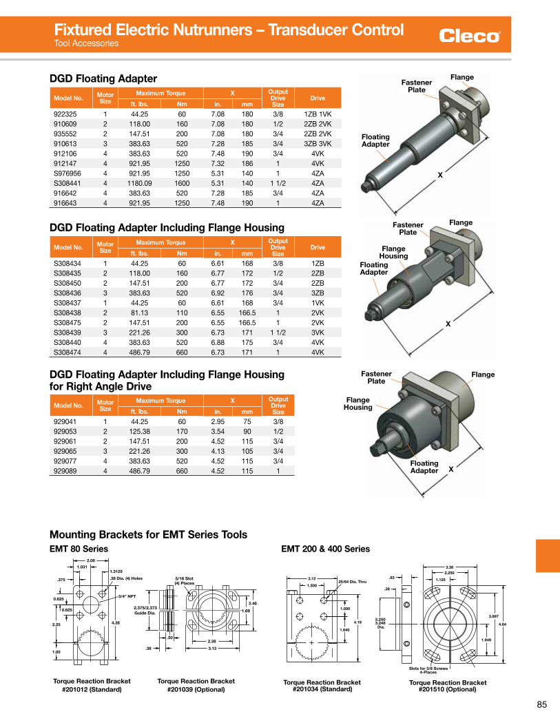
85
Fixtured Electric Nutrunners – Transducer ControlTool Accessories
X
FlangeFastener
Plate
Floating Adapter
X
FlangeFastener Plate
Floating Adapter
Flange Housing
X
FlangeFastener Plate
Floating Adapter
Flange Housing
Model No. Motor Size
Maximum Torque X OutputDriveSize
Driveft. lbs. Nm in. mm
922325 1 44 .25 60 7 .08 180 3/8 1ZB 1VK910609 2 118 .00 160 7 .08 180 1/2 2ZB 2VK935552 2 147 .51 200 7 .08 180 3/4 2ZB 2VK910613 3 383 .63 520 7 .28 185 3/4 3ZB 3VK912106 4 383 .63 520 7 .48 190 3/4 4VK912147 4 921 .95 1250 7 .32 186 1 4VKS976956 4 921 .95 1250 5 .31 140 1 4ZAS308441 4 1180 .09 1600 5 .31 140 1 1/2 4ZA916642 4 383 .63 520 7 .28 185 3/4 4ZA916643 4 921 .95 1250 7 .48 190 1 4ZA
DGD Floating Adapter
Model No. Motor Size
Maximum Torque X OutputDriveSize
Driveft. lbs. Nm in. mm
S308434 1 44 .25 60 6 .61 168 3/8 1ZBS308435 2 118 .00 160 6 .77 172 1/2 2ZBS308450 2 147 .51 200 6 .77 172 3/4 2ZBS308436 3 383 .63 520 6 .92 176 3/4 3ZBS308437 1 44 .25 60 6 .61 168 3/4 1VKS308438 2 81 .13 110 6 .55 166 .5 1 2VKS308475 2 147 .51 200 6 .55 166 .5 1 2VKS308439 3 221 .26 300 6 .73 171 1 1/2 3VKS308440 4 383 .63 520 6 .88 175 3/4 4VKS308474 4 486 .79 660 6 .73 171 1 4VK
DGD Floating Adapter Including Flange Housing
Model No. Motor Size
Maximum Torque X OutputDriveSizeft. lbs. Nm in. mm
929041 1 44 .25 60 2 .95 75 3/8929053 2 125 .38 170 3 .54 90 1/2929061 2 147 .51 200 4 .52 115 3/4929065 3 221 .26 300 4 .13 105 3/4929077 4 383 .63 520 4 .52 115 3/4929089 4 486 .79 660 4 .52 115 1
DGD Floating Adapter Including Flange Housing for Right Angle Drive
DIA.
.50
1.06
2.47
16.63 FOR EMT80-2P, -3P, -4P AND -6P
5.20
3/8 AVAILABLE1/2 SQ. DRIVE STANDARD
2.53 DIA
2.65
1.65
2.38
3.13
2.06
1.3125
.375
1.031
(4) Places
4.38
Torque Reaction Bracket#201012 (Standard)
Torque Reaction Bracket#201039 (Optional)
2.25
1.00
0.625
0.625
.50
.38
Guide Dia.2.375/2.373
3/4” NPT
5/16 Slot.38 Dia. (4) Holes
2.46
1.69
EMT80-10P-3/8-29PEMT80-6P-1/2-29PEMT80-4P-1/2-29PEMT80-3P-1/2-29P570409
570401570408570407
PART NO. MODEL Nm
108735529
ft-lbs
300
152225
rpm552
40
8054
22
EMT80-P FIXTUREDRIGHT ANGLE NUTRUNNERSWITH 29-PIN CONNECTOR
-P ANGLE HEAD CAPACITY: 60 FTLBSNOTE: TOOL OUTPUT EXCEEDS ANGLE HEAD CAPACITY
Mounting Brackets for EMT Series Tools
3.2483.250
.38
Slots for 3/8 Screws4-Places
Torque Reaction Bracket#201034 (Standard)
Torque Reaction Bracket#201510 (Optional)
1/2", 5/8', & 3/4 SQUARE DRIVE AVAILABLE
EMT200-V FIXTURED
WITH 29-PIN CONNECTORRIGHT ANGLE NUTRUNNERS
EMT200-10V-1/2-29PEMT200-5V-5/8-29PEMT200-4V-5/8-29PEMT200-3V-5/8-29P
200V98.DWG 11/97ACAD FILE:
570511570512
570507570513
PART NO. MODEL Nm
260.0176.0132.072.0
ft-lbs
187126
rpm
250460
129.3192.0
97.353.3
DIA.
21.00 FOR EMT200-2V, -3V, -4V AND -5V
3.69
1.67
.63
5.25
2.16
25/64 Dia. Thru
Dia.
3.12
4.19
1.640
1.000
1.500
2.73
3.25 DIA
-V ANGLE HEAD CAPACITY: 180 FTLBSNOTE: TOOL OUTPUT EXCEEDS ANGLE HEAD CAPACITY
4.84
3.897
1.949
3.38
.63 1.125
2.250
2.19DIA.
EMT 80 Series EMT 200 & 400 Series
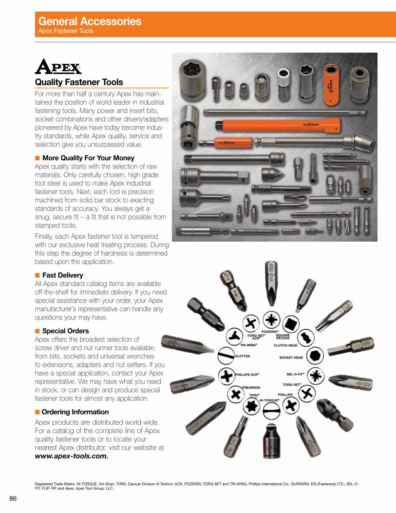
86
Quality Fastener ToolsFor more than half a century Apex has main-tained the position of world leader in industrial fastening tools. Many power and insert bits, socket combinations and other drivers/adapters pioneered by Apex have today become indus-try standards, while Apex quality, service and selection give you unsurpassed value.
■ More Quality For Your MoneyApex quality starts with the selection of raw materials. Only carefully chosen, high grade tool steel is used to make Apex industrial fastenertools.Next,eachtoolisprecisionmachined from solid bar stock to exacting standardsofaccuracy.Youalwaysgetasnug, secure fit – a fit that is not possible from stamped tools.
Finally, each Apex fastener tool is tempered with our exclusive heat treating process. During this step the degree of hardness is determined based upon the application.
■ Fast DeliveryAll Apex standard catalog items are available off-the-shelf for immediate delivery. If you need special assistance with your order, your Apex manufacturer’s representative can handle any questions your may have.
■ Special OrdersApex offers the broadest selection of screw driver and nut runner tools available, from bits, sockets and universal wrenches to extensions, adapters and nut setters. If you have a special application, contact your Apex representative. We may have what you need in stock, or can design and produce special fastener tools for almost any application.
■ Ordering InformationApex products are distributed world-wide. For a catalog of the complete line of Apex quality fastener tools or to locate your nearest Apex distributor, visit our website at www.apex-tools.com.
Registered Trade Marks: HI-TORQUE, Voi-Shan; TORX, Camcar Division of Textron; ACR, POZIDRIV, TORQ-SET and TRI-WING, Phillips International Co .; SUPADRIV, EIS (Fasteners) LTD .; SEL-O-FIT, FLIP-TIP, and Apex, Apex Tool Group, LLC .
POZIDRIV®
TORQ-SET®
ACR®
TORQ-SET®
SEL-O-FIT®
SOCKET HEAD
CLUTCH HEAD
SQUARE RECESS
PHILLIPS ACR®
TORX®
HI-TORQUE®
PHILLIPS®
FREARSON
TRI-WING®
SLOTTED
General AccessoriesApex Fastener Tools

87
Insert Bits(1/4” hex for socket head cap screws and set screws)
A
Insert BitsUsed with Bit Holders (all bits are 1 .0” (25 .4 mm) long)
PartNumber
Hex Size(in.)
“A” CapScrew
SetScrewin. mm
185-00 1/16 1 .00 25 .4 1 5 .6185-0 5/64 1 .00 25 .4 2 .3 8185-1 3/32 1 .00 25 .4 4 .5 10185-9 7/64 1 .00 25 .4 6 —185-2 1/8 1 .00 25 .4 8 1/4185-10 9/64 1 .00 25 .4 8 —185-3 5/32 1 .31 33 .3 10 5/16185-4 3/16 1 .31 33 .3 1/4 3/8185-5 7/32 1 .31 33 .3 — 7/16185-6 1/4 1 .31 33 .3 5/16 1/2185-7 5/16 1 .25 31 .8 3/8 5/8185-8 3/8 1 .25 31 .8 7/16, 1/2 3/4
Square Drive Adapter(1/4” hex drive sockets) Use with Quick Change and Bit & Finder Models, except as noted .
B
A
PartNumber
“A”Sq. Drive
“B” BushingNumberin. mm
EX250-2 1/4 2 .00 50 .8 –EX250-3 1/4 3 .00 76 .2 847295*EX250-4 1/4 4 .00 101 .6 –EX250-6 1/4 6 .00 152 .4 –EX370 3/8 1 .63 41 .3 –EX370-3 3/8 3 .00 76 .2 847295*EX500-2 1/2 2 .00 50 .8 –EX500-3 1/2 3 .00 76 .2 –
*Note: Required for bit and finder models .
Hex ExtensionsPart
NumberHex
Drive (in.)Type ofLock
Overall Length
in. mm
Male Hex Drive with 1/2” Male Square
EX-501-3 7/16 Pin 3 76EX-501-4 7/16 Pin 4 102EX-501-6 7/16 Pin 6 152
Male Hex Drive with 3/8” Male Square
EX-371-3 7/16 Pin 3 76EX-371-4 7/16 Pin 4 102EX-371-6 7/16 Pin 6 152
Hex Drive NutsettersPart
NumberSize(in.)
OverallLength (in.)
Socket NoseDiameter (in.)
7/16” 6 Point
6N-1416-3 1/2 3 13/166N-1416-4 1/2 4 13/166N-1418-3 9/16 3 7/86N-1418-4 9/16 4 7/86N-1420-3 5/8 3 16N-1420-6 5/8 6 1
PointSize
Part Number Wood Machine & Self-Tapping
Phillips Pozi-Drive Flat & Oval Round Flat, Oval & Pan Fillister Truss Binding
0 446-0 446-1P2D 0 .1 0 .1 0 .1 0 .1 0 .1 0 .11 HPL-1 440-1PZD 2-4 2-4 2-4 2-4 2-4 2-42 HPI-2 440-2PZD 5-8 5-10 5-10 5-10 6-10 5-103 HPI-3 440-3PZD 10-16 12-16 12-16 12-5/16 12-16 12-1/4
6 Point SocketsPart No. Hex
OpeningOverallLength
Nose EndDiameter
Drive EndDiameter
OpeningDepth
3/8” Square Drive Sockets, SAE3112 3/8 1 1/4 19/32 3/4 1/43114 7/16 1 1/2 11/16 3/4 9/323116 7/16 1/2 1 1/2 13/16 11/323118 7/16 9/16 1-1/2 7/8 7/16
1/2” Square Drive Sockets, SAE5112 3/8 1 1/2 5/8 15/16 1/45114 7/16 1 1/2 11/16 15/16 9/325116 1/2 1 1/2 13/16 15/16 11/325120 5/8 1 1/2 1 1 7/165122 11/16 1 1/2 1 1/8 1 1/8 7/165124 3/4 1 1/2 1 1/8 1 1/8 15/32
3/4” Square Drive Sockets, SAE7128 7/8 2 1 1/2 1 1/2 9/167132 1 2 1 5/8 1 5/8 5/87136 1 1/8 2 1/8 1 3/4 1 3/4 3/47140 1 1/4 2 1/8 2 1 3/4 13/167144 1 3/8 2 1/8 2 1/8 2 1/8 13/167148 1 1/2 2 1/4 2 1/4 2 1/8 1
1” Square Drive Sockets, SAE8132 1 2 1/8 1 5/8 2 13/168140 1 1/4 2 1/8 2 1/8 2 1/8 13/168144 1 3/8 2 1/8 2 1/8 2 1/8 13/168148 1 1/2 2 1/4 2 1/4 2 1/8 15/168156 1 3/4 2 3/8 2 5/8 2 5/8 11/168164 2 2 5/8 3 2 5/8 1 3/16
1 1/2” Square Drive Sockets, SAE9156 1 3/4 2 7/8 2 7/8 3 1 1/89160 1 7/8 3 3 1/8 3 1 1/49164 2 3 1/8 3 1/4 3 1/4 1 3/89172 2 1/4 3 1/4 3 3//8 3 1/4 1 1/2
3/8” Square Drive Sockets, Metric12mm13 12 38 .1 19 .1 19 .1 7 .214mm13 14 38 .1 22 .2 22 .2 11 .116mm13 16 38 .1 23 .8 23 .8 11 .1
1/2” Square Drive Sockets, Metric16mm15 16 38 .1 25 .4 25 .4 11 .118mm15 18 38 .1 28 .6 28 .6 11 .120mm15 20 38 .1 31 .7 31 .7 11 .922mm15 22 38 .1 33 .3 33 .3 14 .3
5/8” Square Drive Sockets, Metric24mm16 24 51 38 .1 38 .1 15 .9
3/4” Square Drive Sockets, Metric28mm17 28 54 44 .4 44 .4 19 .130mm17 30 54 47 .6 44 .4 19 .132mm17 32 54 50 .8 44 .4 20 .634mm17 34 54 54 .0 54 .0 20 .636mm17 36 57 57 .1 54 .0 23 .8
1” Square Drive Sockets, Metric32mm18 32 54 54 .0 54 .0 20 .634mm18 34 54 54 .0 54 .0 20 .636mm18 36 57 57 .1 54 .0 23 .938mm18 38 57 57 .1 54 .0 23 .942mm18 42 60 63 .5 54 .0 23 .946mm18 46 64 69 .8 66 .7 26 .9

88
Quality Anti-Mar Fastener Tools Begin With Quality Fastener Tools.
Apex µ-Guard™ provides a protective barrier between genuine Apex fastener tools and your finely finished workpiece. The free-spinning patent-pending design provides maximum protection for polished and highly sensitive surfaces.
Apex µ-Guard™ covering is made of a thermo plastic urethane (TPU elastomer) which cushions against costly incidental side impacts. It offers the lowest coefficient of friction for maximum tool efficiency. It is also non-removable for tamper resistance.
With Apex µ-Guard™ you get the proven Apex fastener tool fit and performance plus the best protection available against marring and in-system damage.
µ-Guard™ is your guard against the potential hazards caused by rotational friction.
Prevents Side Impact Damage
Free-Spinning Design
Virtually Damage Free
If it doesn’t say Apex on the outside, how can
you be sure of what’s on the inside?
General AccessoriesApex µ-Guard

89
µ-Guard Sockets(Includes socket and cover)
Part Number SocketDrive End Socket
LengthFastener End Assembly
FeaturesSize Type Sex Size Type SexUGS-AB710 10MM21 1/4 Square F standard 10 mm Hex F FSUGS-AB710-01 M-10MM21 1/4 Square F standard 10 mm Hex F FS, MUGS-AB710-02 MB-10MM21 1/4 Square F standard 10 mm Hex F FS, M, BUGS-BA610 10MM13 3/8 Square F standard 10 mm Hex F FSUGS-BA610-01 M-10MM13 3/8 Square F standard 10 mm Hex F FS, MUGS-BB710 10MM23 3/8 Square F long 10 mm Hex F FSUGS-BB710-01 M-10MM23 3/8 Square F long 10 mm Hex F FS, MUGS-BB710-02 MB-10MM23 3/8 Square F long 10 mm Hex F FS, M, BUGS-BB713 13MM23 3/8 Square F long 13 mm Hex F FSUGS-BB713-01 M-13MM23 3/8 Square F long 13 mm Hex F FS, MUGS-BB713-02 MB-13MM23 3/8 Square F long 13 mm Hex F FS, M, BUGS-CB713 13MM25 1/2 Square F long 13 mm Hex F FSUGS-CB713-03 SF-13MM25 1/2 Square F long 13 mm Hex F FS, SFUGS-CB715 15MM25 1/2 Square F long 15 mm Hex F FSUGS-CB715-03 SF-15MM25 1/2 Square F long 15 mm Hex F FS, SFUGS-CB718 18MM25 1/2 Square F long 18 mm Hex F FSUGS-CB718-03 SF-18MM25 1/2 Square F long 18 mm Hex F FS, SF
If your tool is not shown in the table of representative products above, please contact your Apex representative.
Part Number ExtensionDrive End Extension
LengthSocket End Assembly
Features*Size Type Sex Size Type SexUGE-A2A EX-250-2 1/4 Hex M 2 1/4 Square M FSUGE-A4A EX-250-4 1/4 Hex M 4 1/4 Square M FSUGE-A6A EX-250-6 1/4 Hex M 6 1/4 Square M FSUGE-B2A EX-370-2 1/4 Hex M 2 3/8 Square M FSUGE-B4A EX-370-4 1/4 Hex M 4 3/8 Square M FSUGE-B6A EX-370-6 1/4 Hex M 6 3/8 Square M FSUGE-B3C EX-376-3 3/8 Square F 3 3/8 Square M FSUGE-B6C EX-376-6 3/8 Square F 6 3/8 Square M FSUGE-B12C EX-376-12 3/8 Square F 12 3/8 Square M FSUGE-C4C EX-508-4 1/2 Square F 4 1/2 Square M FSUGE-C8C EX-508-8 1/2 Square F 8 1/2 Square M FSUGE-C12C EX-508-12 1/2 Square F 12 1/2 Square M FS
If your tool is not shown in the table of representative products above, please contact your Apex representative.
µ-Guard Extensions(Includes extension and cover)
*Features AbbreviationsFS Free Spinning Tool is able to rotate independently of CoverM Magnetic Tool includes magnet to hold the position of the fastener during fastening operationB Bolt Clearance Tool is spring-loaded to allow bolt or nut to retract into the socket bodySF Surface Drive Tool has radiused corners to allow easier alignment and engagement of fastenerET Exposed Tip Cover extends beyond end of Bit Holder to shield the majority of a standard 1 inch long Insert Bit .
Tip of Insert Bit will not be covered to allow easier fastener engagement .QR Quick Release Tool has tension feature to allow quick & easy change between bits Cover will not extend beyond end of Bit HolderNotes:Reported lengths are based on uncovered tool length only for reference . Cover may extend beyond end of tool by 2 mm unless otherwise noted .
µ-Guard Bit Holders(Includes bit holder and cover)
Part Number Bit HolderDrive End Socket
LengthFastener End Assembly
FeaturesSize Type Sex Size Type SexUGH-1NAA M-490 1/4 Hex M 2 31/32 1/4 Hex F FS, M, ETUGH-1AAA M-490-2 1/4 Hex M 2 1/4 Hex F FS, M, ETUGH-2NBG 838 3/8 Square F 1 1/2 1/4 Hex F FS, ETUGH-1NBG M-838 3/8 Square F 2 5/8 1/4 Hex F FS, M, ETUGH-2NBC 835 3/8 Square F 1 1/2 5/16 Hex F FS, ETUGH-1NBC M-835 3/8 Square F 2 3/4 5/16 Hex F FS, M, ETUGH-2NBD 855 1/2 Square F 1 1/2 5/16 Hex F FS, ETUGH-1NBD M-855 1/2 Square F 2 3/4 5/16 Hex F FS, M, ETUGH-2NCK QR-308 3/8 Square F 1 3/4 1/4 Hex F FS, QRUGH-2NCF QR-508 1/2 Square F 2 1/8 1/4 Hex F FS, QRUGH-2NCJ QR-314 3/8 Square F 2 7/16 Hex F FS, QRUGH-2NCL QR-514 1/2 Square F 2 1/8 7/16 Hex F FS, QR
If your tool is not shown in the table of representative products above, please contact your Apex representative.

90
0 .100 .0039
0 .200 .0079
0 .300 .0118
0.397 .0156 1/640 .400 .0157
0 .500 .0197
0 .600 .0236
0 .700 .0276
0.794 .0313 1/320 .800 .0315
0 .900 .0354
1 .000 .0394
1 .100 .0433
1.191 .0469 3/641 .200 .0472
1 .300 .0512
1 .400 .0551
1 .500 .0591
1.588 .0625 1/161 .600 .0630
1 .700 .0669
1 .800 .0709
1 .900 .0748
1.984 .0781 5/642 .000 .0878
2 .100 .0827
2 .200 .0866
2 .300 .0906
2.381 .0938 3/322 .400 .0945
2 .500 .0984
2 .600 .1024
2 .700 .1063
2.778 .1094 7/642 .800 .1102
2 .900 .1142
3 .000 .1181
3 .100 .1220
3.175 .1250 1/83 .200 .1260
3 .300 .1299
3 .400 .1339
3 .500 .1378
3.572 .1406 9/643 .600 .1417
3 .700 .1457
3 .800 .1496
3 .900 .1535
3.969 .1563 5/324 .000 .1575
4 .100 .1624
4 .200 .1654
4 .300 .1693
4.366 .1719 11/644 .400 .732
4 .500 .1772
4 .600 .1811
4 .700 .1850
4.763 .1875 3/164 .800 .1890
4 .900 .1929
5 .000 .1969
5 .100 .2008
5.159 .2031 13/645 .200 .2047
5 .300 .2087
5 .400 .2126
5 .500 .2165
5.556 .2188 7/325 .600 .2205
5 .700 .2244
5 .800 .2283
5 .900 .2323
5.953 .2344 15/646 .000 .2362
6 .100 .2402
6 .200 .2441
6 .300 .2480
6.350 .2500 1/46 .400 .2520
6 .500 .2559
6 .600 .2598
6 .700 .2638
6.747 .2656 17/646 .800 .2677
6 .900 .2717
7 .000 .2756
7 .100 .2795
7.144 .2813 9/327 .200 .2835
7 .300 .2874
7 .400 .2913
7 .500 .2953
7.541 .2969 19/647 .600 .2992
7 .700 .3031
7 .800 .3071
7 .900 .3110
7.938 .3125 5/168 .000 .3150
8 .100 .3189
8 .200 .3228
8 .300 .3268
8.334 .3281 21/648 .400 .3307
8 .500 .3346
8 .600 .3386
8 .700 .3425
8.731 .3438 11/328 .800 .3465
8 .900 .3504
9 .000 .3543
9 .100 .3583
9.128 .3594 23/649 .200 .3622
9 .300 .3661
9 .400 .3701
9 .500 .3740
9.525 .3750 3/8 9 .700 .3819
9 .800 .3858
9 .900 .3898
9.922 .3902 25/6410 .000 .3937
10 .100 .3976
10 .200 .4016
10 .300 .4055
10.319 .4063 13/3210 .400 .4094
10 .500 .4134
10 .600 .4173
10 .700 .4219
10.716 .4219 27/6410 .800 .4252
10 .900 .4291
11 .000 .4331
11 .100 .4370
11.113 .4375 7/1611 .200 .4409
11 .300 .4449
11 .400 .4488
11 .500 .4528
11.509 .4531 29/6411 .600 .4567
11 .700 .4606
11 .800 .4646
11 .900 .4685
11.906 .4688 15/3212 .000 .4724
12 .100 .4764
12 .200 .4803
12 .300 .4843
12.303 .4844 31/6412 .400 .4882
12 .500 .4921
12 .600 .4961
12.700 .5000 1/212 .800 .5039
12 .900 .5079
13 .000 .5118
13.097 .5156 33/6413 .100 .5157
13 .200 .5197
13 .300 .5236
13 .400 .5276
13.494 .5313 17/3213 .500 .5315
13 .600 .5354
13 .700 .5394
13 .800 .5433
13.891 .5469 35/6413 .900 .5472
14 .000 .5512
14 .100 .5551
14 .200 .5591
14.288 .5625 9/1614 .300 .5630
14 .400 .5669
14 .500 .5709
14 .600 .5748
14.684 .5781 37/6414 .700 .5787
14 .800 .5827
14 .900 .5866
15 .000 .5906
15.081 .5938 19/3215 .100 .5945
15 .200 .5984
15 .300 .6024
15 .400 .6063
15.478 .6094 39/6415 .500 .6102
15 .600 .6142
15 .700 .6181
15 .800 .6220
15.875 .6250 5/815 .900 .6250
16 .000 .6299
16 .100 .6339
16 .200 .6378
16.272 .6406 41/6416 .300 .6417
16 .400 .6457
16 .500 .6496
16 .600 .6535
16.669 .6563 21/3216 .700 .6575
16 .800 .6614
16 .900 .6654
17 .000 .6693
17.066 .6719 43/6417 .100 .6732
17 .200 .6772
17 .300 .6811
17 .400 .6850
17.463 .6875 11/1617 .500 .6890
17 .600 .6929
17 .700 .6968
17 .800 .7008
17.859 .7031 45/6417 .900 .7047
18 .000 .7087
18 .100 .7126
18 .200 .7165
18.256 .7188 23/3218 .300 .7205
18 .400 .7244
18 .500 .7283
18 .600 .7323
18.653 .7344 47/6418 .700 .7362
18 .800 .7402
18 .900 .7441
19 .000 .7480
19.050 .7500 3/419 .100 .7520
19 .200 .7559
19 .300 .7598
19 .400 .7638
19.447 .7656 49/6419 .500 .7677
19 .600 .7717
19 .700 .7756
19 .800 .7795
19.844 .7813 25/3219 .900 .7835
20 .000 .7874
20 .100 .7913
20 .200 .7953
20.241 .7969 51/6420 .300 .7992
20 .400 .8031
20 .500 .8071
20 .600 .8110
20.638 .8125 13/1620 .700 .8150
20 .800 .8189
20 .900 .8228
21 .000 .8268
21.034 .8182 53/6421 .100 .8307
21 .200 .8307
21 .200 .8346
21 .300 .8386
21 .400 .8425
21.431 .8438 27/3221 .500 .8465
21 .600 .8504
21 .700 .8543
21 .800 .8583
21.828 .8594 55/9421 .900 .8622
22 .000 .8661
22 .100 .8701
22 .200 .8740
22.225 .8750 7/822 .300 .8780
22 .400 .8819
22 .500 .8858
22 .600 .8898
22.622 .8906 57/6422 .700 .8937
22 .800 .8976
22 .900 .9016
23 .000 .9055
23.019 .9063 29/3223 .100 .9094
23 .200 .9134
23 .300 .9173
23 .400 .9213
23.416 .9219 59/6423 .500 .9252
23 .600 .9291
23 .700 .9331
23 .800 .9370
23 .900 .9409
24 .000 .9449
24 .100 .9488
24 .200 .9528
24.209 .9531 61/6424 .300 .9567
24 .400 .9606
24 .500 .9646
24 .600 .9685
24.606 .9688 31/3224 .700 .9724
24 .800 .9764
24 .900 .9803
25 .000 .9843
25.003 .9844 63/6425 .100 .9882
25 .200 .9921
25 .300 .9961
25.400 1.000 1
mm Dec. in. mm Dec. in. mm Dec. in. mm Dec. in. mm Dec. in.m
Conversion TablesMillimeter – Decimal – Fraction

91
5 0 .610 1 .115 1 .720 2 .325 2 .830 3 .435 4 .040 4 .545 5 .1
50 5 .760 6 .870 7 .980 9 .090 10 .2100 11 .3110 12 .4120 13 .6130 14 .7
140 15 .8150 17 .0160 18 .1170 19 .2180 20 .3190 21 .5200 22 .6
Torque Conversion – In. Lbs. (Nm)
In. Lbs. Nm In. Lbs. Nm In. Lbs. Nm
Torque Conversion Factors
To Convert Into Multiply By
Inch Pounds Foot Pounds 0 .0835Inch Pounds Newton meters 0 .1130Inch Pounds Kg-meters 0 .0115Inch Pounds Kg-Cm 1 .1519Foot Pounds Inch Pounds 12 .000Foot Pounds Newton meters 1 .3560Foot Pounds Kg-meters 0 .1382Foot Pounds Kg-Cm 13 .8240
Newton Meters Inch Pounds 8 .8440Newton Meters Foot Pounds 0 .7370Newton Meters Kg-meters 0 .1020Newton Meters Kg-Cm 10 .2000
Kg meters Inch Pounds 86 .8100Kg meters Foot Pounds 7 .2340Kg meters Newton-meters 9 .8040
Kg Cm Inch Pounds 0 .8681Kg Cm Foot Pounds 0 .0723Kg Cm Newton-meters 0 .0980
Inch Bolt Torque TableSAE J429 and ASME 574
Steel Grade SAE 5 SAE 8 Socket HeadCap Screws
Nom Dia - Pitch
Torque in Pound Foot or (Pound Inch)
Dry Lubed Dry Lubed Dry Lubed
1/4-20 (101) (76) (143) (107) (168) (120)1/4-28 (116) (87) (147) (123) (192) (144)5/16-18 (209) (157) (295) (221) (348) (264)5/16-24 (231) (174) (327) (245) (384) (288)3/8-16 (372) (276) 44 33 51 383/8-24 (420) (312) 49 37 58 437/16-14 49 37 70 52 81 617/16-20 55 41 78 58 91 681/2-13 75 57 106 80 124 931/2-20 85 64 120 90 140 1055/8-11 150 113 212 159 238 1795/8-18 170 127 240 180 270 2023/4-10 267 200 376 282 423 3173/4-16 297 223 420 315 472 3547/8-9 429 322 606 455 682 5117/8-14 474 355 669 502 752 5641-8 644 483 909 681 1022 7671-12 722 542 1020 765 1147 860
Metric Bolt Torque TableISO 898
PropertyClass
8.8 10.9 12.9 Socket HeadCap Screw
Torque in Newton Meter - NmNom Size x Pitch Dry Lubed Dry Lubed Dry Lubed
M5 x 0 .80 6 .1 4 .6 8 .8 6 .7 10 .3 7 .7M6 x 1 .00 10 .4 7 .8 15 11 .2 17 .6 13 .1M7 x 1 .00 17 .6 13 .1 25 .1 18 .9 29 .4 22M8 x 1 .25 25 .4 19 .1 37 .6 27 .3 42 .6 32 .1M10 x 1 .50 50 38 72 54 84 64M12 x 1 .75 88 66 126 94 146 110M14 x 2 .00 141 106 201 150 235 176M16 x 2 .00 218 164 312 233 365 274M18 x 2 .50 301 226 431 323 504 378M20 x 2 .50 426 319 609 457 712 534M22 x 2 .50 580 435 831 624 971 728M24 x 3 .00 736 552 1052 789 1231 923M27 x 3 .00 1079 809 1544 1158 1805 1353M30 x 3 .50 1463 1097 2092 1570 2446 1834M33 x 3 .50 1990 1493 2849 2137 3328 2497M36 x 4 .00 2557 1918 3659 2744 4276 3208
Lubed means cleaned dry bolts lubricated with a standard medium viscosity machine oil . Lubricate all contact areas of the bolts and washers . Lubricating the bolts is the suggested method .
Miscellaneous Conversion Factors
To Convert Into Multiply By
Inches Millimeters 25 .4000Millimeters Inches 0 .0394
Pounds Kilograms 0 .4536Kilograms Pounds 2 .2050
psi bar 0 .069bar psi 14 .5
Air Pressure Conversion
PSI kPa* Bar**
85 586 5 .990 620 6 .295 655 6 .6100 690 6 .9125 860 8 .6
*Preferred: Approximate to the nearest 5 kPa .**Approximate to the nearest 0 .5 Bar .
1 1 .362 2 .73 4 .14 5 .45 6 .86 8 .17 9 .58 10 .99 12 .210 13 .611 14 .912 16 .313 17 .614 19 .015 20 .316 21 .717 23 .118 24 .419 25 .820 27 .121 28 .522 29 .823 31 .224 32 .525 33 .926 35 .327 36 .628 38 .029 39 .330 40 .731 42 .032 43 .4
33 44 .834 46 .135 47 .536 48 .837 50 .238 52 .039 52 .940 54 .241 55 .642 57 .043 58 .344 60 .045 61 .046 62 .447 63 .748 65 .149 66 .450 67 .851 69 .252 70 .553 71 .954 73 .255 74 .656 75 .957 77 .358 78 .759 80 .060 81 .461 82 .762 84 .163 85 .464 86 .8
65 88 .166 90 .067 90 .968 92 .269 93 .670 94 .971 96 .372 97 .673 99 .074 100 .375 102 .076 103 .177 104 .478 105 .879 107 .180 108 .581 110 .082 111 .283 112 .684 114 .085 115 .386 117 .087 118 .088 119 .389 121 .090 122 .091 123 .492 125 .093 126 .194 127 .595 129 .096 130 .2
97 131 .598 133 .099 134 .2100 135 .6110 149 .2115 156 .0120 163 .0125 170 .0130 176 .3135 183 .1140 190 .0145 197 .0150 203 .4155 210 .2160 217 .0165 224 .0170 231 .0175 237 .3180 244 .1185 251 .0190 258 .0195 264 .4200 271 .2225 305 .1250 339 .0275 373 .0300 407 .0350 475 .0400 542 .4
Torque Conversion – Ft. Lbs. (Nm)
Ft. Lbs. Nm Ft. Lbs. Nm Ft. Lbs. Nm Ft. Lbs. Nm
Conversion TablesTorque – Air Pressure – Miscellaneous

92
Sales & Service Centers
Please note that all locations may not service all products . Please contact the nearest Apex Tool Group Sales & Service Center for the appropriate facility to handle your service requirements .
D E T R O I T , M I C H I G A N
Apex Tool GroupSales & Service Center2630 Superior CourtAuburn Hills, MI 48326Tel: (248) 393 5640Fax: (248) 391 6295
H O U S T O N , T E X A S
Apex Tool GroupSales & Service Center6550 West Sam Houston Parkway North, Suite 200Houston, TX 77041Tel: (713) 849 2364Fax: (713) 849 2047
S E A T T L E , W A S H I N G T O N
Apex Tool GroupSales & Service Center2865 152nd Ave N .E . Redmond, WA 98052Tel: (425) 497 0476Fax: (425) 497 0496 L E X I N G T O N , S C
Apex Tool Group670 Industrial DriveLexington, SC 29072Tel: (800) 845 5629Tel: (803) 951 7544Fax: (803) 358 7681
L O S A N G E L E S , C A L I F O R N I A
Apex Tool GroupSales & Service Center6881 Stanton Avenue, Unit B Buena Park, CA 90621Tel: (714) 994-1491Fax: (714) 994-9576
Y O R K , P E N N S Y L V A N I A
Apex Tool GroupSales & Service CenterYork Service Center 3990 E . Market Street York, PA 17402Tel: (717) 755 2933Fax: (717) 757 5063
B R A Z I L
Cooper Tools Industrial Ltda . An Apex Tool Group, LLC companyAv . Liberdade, 4055Zona Industrial - Iporanga18087-170 SorocabaSP BrazilTel: +55 15 2383929Fax: +55 15 2383260
C A N A D A
Apex Tool GroupSales & Service Center5925 McLaughlin RoadMississauga, Ont . L5R 1B8 CanadaTel: (905) 501 4785Fax: (905) 501 4786
C H I N A
Cooper (China) Co ., Ltd .An Apex Tool Group, LLC company955 Sheng Li Road,Heqing Pudong, ShanghaiChina 201201Tel: +86 21 28994176Fax: +86 21 51118446
E N G L A N D
Apex Tool Group GmbH & Co . OHGC/O Spline GaugesPiccadilly, Tamworth,Staffordshire B78 2ER United KingdomTel: +44 1827 8741 28Fax: +44 1827 8741 28
F R A N C E
Apex Tool Group SAS 25 rue Maurice ChevalierB . P . 2877831 Ozoir-la-Ferrière CedexFranceTel: +33 1 64 43 22 00 Fax: +33 1 64 43 17 17
G E R M A N Y
Apex Tool Group GmbH & Co . OHGIndustriestraße 173463 WesthausenGermanyTel: +49 (0) 73 63 81 0Fax: +49 (0) 73 63 81 222
H U N G A R Y
Cooper Tools Hungaria Kft .An Apex Tool Group, LLC companyBerkenyefa sor 7Pf: 640 9027 GyörHungaryTel: +36 96 66 1383Fax: +36 96 66 1135
M E X I C O
Cooper Tools de México S .A . de C .V .An Apex Tool Group, LLC companyVialidad El Pueblito #103 Parque Industrial QuerétaroQuerétaro, QRO 76220MexicoTel: +52 (442) 211 3800Fax: +52 (442) 103 0443
www.apextoolgroup.com
www.apextoolgroup.eu

93
Order Catalogs & Literature On-Line
One Of The Broadest Range Of Tools In The World Is At Your Fingertips!Apex Tool Group covers a wide range of industrial markets, including aerospace, automotive, foundries, furniture, general industry, metal fabrication, petroleum, power generation, shipbuilding, and transportation. These markets have been served by Apex Tool Group’s brands for many decades, by offering our customers solutions and products that meet their demanding productivity requirements.
To receive a product catalog quickly, just go to www.apextoolgroup.com. Select the literature you want. Then complete the “Contact Information” form, hit “Submit Request” and your order will be processed immediately.Materialsnormallyarrivewithin48hours.
Below are a few of our more popular power tools catalogs
Cleco Pneumatic Assembly ToolsA full line of industrial pneumatic assembly tools from screwdrivers to nutrunners to impacts.(Catalog # SP-1000)www.clecotools.com
Cleco D.C. Electric Assembly ToolsA complete line of industrial D.C. electric assembly tools and controllers.(Catalog # SP-1020)www.clecotools.com
Dotco/Cleco Material Removal ToolsA full line of pneumatic material removal tools including drills, sanders, and grinders.(Catalog # SP-102)www.dotco-tools.com
Cleco Power MotorsA comprehensive line of industrial pneumatic motors for a multitude of applications.(Catalog # SP-104)www.clecotools.com
Master Power Industrial Air ToolsA complete line of industrial pneumatic tools for assembly and material removal applications.(Catalog # SP-904)www.masterpowertools.com
Utica Torque ProductsA full line of torque measuring products including torque screwdrivers, torque wrenches and analyzers.(Catalog # SP-301)www.uticatools.com
Airetool Tube Cleaners & ExpandersA complete line of industrial tube cleaners, expanders and installation tools.(Catalog # SP-1100)www.airetools.com
Apex Fastener ToolsA comprehensive line of industrial quality bits, finders, sockets and extensions.(Catalog # TC-100)www.apex-tools.com
Apex Universal JointsIndustrial quality universal joints that can be custom designed for most any application.(Catalog # SP-1400)www.apexuniversal.com
DGD Assembly SystemsA complete line of spindles, D.C. electric assembly tools and controllers for the MVI.(Catalog # SP-703DE/EN)www.apextoolgroup.com

94
200427 ....................................64200428 ....................................64200429 ....................................64201606 ....................................64204014 ....................................64204119 ....................................64204120 ....................................64204122 ....................................64205832 ....................................62205834 ....................................62205838 ....................................62301128 ....................................64301129 ....................................64301130 ....................................64301131 ....................................64301837 ....................................58521041 ....................................64521042 ....................................64521060 ....................................64535833 ....................................62536185 ....................................61541715 ....................................62541757 ....................................61542428 ....................................62542972 ....................................59542973 ....................................59542974 ....................................59542975 ....................................59542991 ....................................61543070 ....................................62543071 ....................................62543230 ....................................62543232 ....................................62543235 ....................................62543414 ....................................61543995 ....................................58550006....................................61910609 ...............................78,85910613 ...............................78,85912106 ...............................78,85912147 ...............................78,85916642 ...............................78,85916643 ...............................78,85922325 ...............................78,85929041 ....................................85929053 ....................................85929061 ....................................85929065....................................85929077 ....................................85929089 ....................................85935144 ....................................58935154 ....................................58935155 ....................................58935157 ....................................58935170 ....................................58935290 ....................................58935377 ....................................58935395 ....................................58935396 ....................................58935552 ...............................78,85935998 ....................................58935999 ....................................58961024 ....................................61961323 ....................................58961341 ....................................58961342 ....................................581110909 ..................................615970716 ..................................59
35007004 ...............................6243287131 ................................6245017152 ................................6248316033................................6249097101 ................................6257217101 ................................6299248150 ................................5999249101 ................................5999249102 ................................5999249103 ................................5999249104 ................................5999249147 ................................5999249148 ................................5999249156 ................................5999249157 ................................5999249158 ................................5999249159 ................................5999249160 ................................5999249161 ................................5999249162 ................................5999249163 ................................5999249164 ................................5999249165 ................................5999249169 ................................5999249181 ................................5917BPYSB05Q........................... 1117BPYSB07Q ........................... 1117BPYSB09Q........................... 1117BPYSB13Q ........................... 1118CAE08AL2 ...........................4418CAE15AM3 ..........................4418CAE16F ................................5018CAE16S131 .........................5218CAE22AM3 ..........................4418CAE23F ...............................5018CAE23S131 .........................5218CAE28AM3 ..........................4418CAE30F ...............................5018CAE30S131 .........................5218CPE06D2 .............................4618CPE06D3P ...........................4718CPE06Q ...............................4618CPE06QP .............................4718CPE12D3 .............................4618CPE12D3P ...........................4718CPE12Q................................4618CPE12QP .............................4718CPE17D3 .............................4618CPE17Q ................................4618CPE22D3 .............................4618CPE31D3 .............................4618CSE06D2 .............................4518CSE06D3P ...........................4718CSE06Q ...............................4518CSE06QP .............................4718CSE06ZA .............................4818CSE12D3 .............................4518CSE12D3P ...........................4718CSE12Q ...............................4518CSE12QP .............................4718CSE12ZA .............................4818CSE17D3 .............................4518CSE17Q ...............................4518CSE17ZA .............................4818CSE22D3 .............................4518CSE31D3 .............................4518EAE08AL2 ........................... 1818EAE15AM3 .......................... 18
18EAE16F ................................2718EAE16S131.....................30,8318EAE22AM3 .......................... 1818EAE23F................................2718EAE23S131 ....................30,8318EAE28AM3 .......................... 1818EAE30F................................2718EAE30S131 ....................30,8318EPE06D2 .............................2218EPE06D3P ...........................2318EPE06Q ...............................2218EPE06QP .............................2318EPE12D3 ..............................2218EPE12D3P ...........................2318EPE12Q ................................2218EPE12QP ..............................2318EPE17D3 ..............................2218EPE17Q ................................2218EPE22D3 .............................2218EPE31D3..............................2218ESE06D2 .............................2018ESE06D3P ...........................2318ESE06Q ...............................2018ESE06QP .............................2318ESE06ZA ........................24,8118ESE12D3 ..............................2018ESE12D3P ...........................2318ESE12Q ................................2018ESE12QP..............................2318ESE12ZA ..............................8118ESE12ZA ..............................2418ESE17D3..............................2018ESE17Q ................................2018ESE17ZA .........................24,8118ESE22D3 .............................2018ESE31D3 .............................201BB-1B011A-1K3MS-1ZA ........811BB-1B011A-1VK3M ...............821BB-1B011A-1WK3M ..............841BB-1B030A-1K1M-1ZA ..........811BB-1B030A-1VK2B................821BB-1B030A-1WK1M ..............841BB-1B050A-1K2M-1ZA .........811BB-1B050A-1VK1M ...............821BB-1B050A-1WK2M ..............841BTSE-1B012A-1M3B-1ZB .....791BTSE-1B012A-1VM3B ...........791BTSE-1B012A-1WM3B ..........791BTSE-1B035A-1M1B-1ZB .....791BTSE-1B035A-1VM1B ...........791BTSE-1B035A-1WM1B ..........791BTSE-1B060A-1M2B-1ZB .....791BTSE-1B060A-1VM2B ...........791BTSE-1B060A-1WM2B .........791BUTSE-1B012A-1M3B-1ZB ...791BUTSE-1B012A-1VM3B ........791BUTSE-1B012A-1WM3B .......791BUTSE-1B035A-1M1B-1ZB ...791BUTSE-1B035A-1VM1B ........791BUTSE-1B035A-1WM1B .......791BUTSE-1B060A-1M2B-1ZB ...791BUTSE-1B060A-1VM2B ........791BUTSE-1B060A-1WM2B .......792BB-2B100A-2K1M-2ZA.........812BB-2B100A-2VK1M ..............822BB-2B100A-2WK1M .............842BB-2B150A-2K2M-2ZA ........812BB-2B150A-2VK2M ..............82
2BB-2B150A-2WK2M .............842BTSE-2B110A-2M1B-2ZB .....792BTSE-2B110A-2VM1B ...........792BTSE-2B110A-2WM1B .........792BTSE-2B200A-2M3B-2ZB ....792BTSE-2B200A-2VM3B ..........792BTSE-2B200A-2WM3B.........792BUTSE-2B110A-2M1B-2ZB ...792BUTSE-2B110A-2VM1B ........792BUTSE-2B110A-2WM1B .......792BUTSE-2B200A-2M3B-2ZB ....792BUTSE-2B200A-2VM3B .......792BUTSE-2B200A-2WM3B ......79301866-10M ...........................61301866-15M ...........................61301866-1M..............................61301866-2M .............................61301866-3M .............................61301866-6M .............................61301866-8M .............................61301877-10M ............................61301877-15M ............................61301877-1M ..............................61301877-20M ...........................61301877-2M..............................61301877-3M .............................61301877-6M .............................61301877-8M .............................61301903-10M ...........................61301903-15M ...........................61301903-1M ..............................61301903-2M .............................61301903-3M .............................61301903-6M .............................61301903-8M .............................61301904-10M ...........................61301904-15M ...........................61301904-1M..............................61301904-2M .............................61301904-3M .............................61301904-6M .............................61301904-8M .............................613BB-3B180A-3K1M-3ZA ........813BB-3B180A-3VK1M ..............823BB-3B180A-3WK1M .............843BB-3B260A-3K2M-3ZA........813BB-3B260A-3VK2M ..............823BB-3B260A-3WK2M ............843BTSE-3B300A-3M2B-3ZB ...793BTSE-3B300A-3VM2B .........793BTSE-3B300A-3WM2B ........793BUTSE-3B300A-3M2B-3ZB ...793BUTSE-3B300A-3VM2B .......793BUTSE-3B300A-3WM2B ......7947BAYSB15AM3 ...................... 1047BAYSB21AM3 ...................... 1047BAYSB28AM3 ..................... 1047BAYSB35AM3 ..................... 1047BAYSB50AM3 ..................... 1047BAYSB70AH4 ...................... 1047BAYSB90AH4 ...................... 1047BCYSB30C1 ........................ 1347BCYSB30C3 ........................ 1347BTYSB20T2 ......................... 1247BTYSB30T3 ......................... 1247BTYSB40T4 ......................... 1248A17006 ................................6248CAE105AH4 ........................44
48CAE110F ..............................5048CAE110H .............................4948CAE110S341 .......................5248CAE135F .............................5048CAE135H .............................4948CAE135MH4 ........................4448CAE135S461.......................5248CAE15AL3 ...........................4448CAE175AX6 .........................4448CAE230AX6 ........................4448CAE230F .............................5048CAE230H.............................4948CAE230S461 ......................5248CAE28AL3 ...........................4448CAE37F ...............................5048CAE37S231 .........................5248CAE41AM3 ..........................4448CAE52F ...............................5048CAE52S231 .........................5248CAE53F ...............................5048CAE53H ...............................4948CAE53S341 ........................5248CAE58AM3 .........................4448CAE58AM4 .........................4448CAE75F ...............................5048CAE75H ...............................4948CAE75S341.........................5248CAE90AH4 ..........................4448CAE95S341 ........................5248CCE30C1 .............................5448CPE125D4 ...........................4648CPE12D2 .............................4648CPE12Q ...............................4648CPE150D4 ...........................4648CPE25D3 .............................4648CPE36D3 .............................4648CPE48D3 .............................4648CPE65D4 .............................4648CPE90D4 .............................4648CSE1152ZB .........................4848CSE125D4 ...........................4548CSE12D2 .............................4548CSE12Q ...............................4548CSE12ZA .............................4848CSE1502ZB .........................4848CSE150D4 ...........................4548CSE1653ZB .........................4848CSE2503ZB ........................4848CSE25D3 .............................4548CSE271ZB ...........................4848CSE361ZB ...........................4848CSE36D3.............................4548CSE48D3 .............................4548CSE602ZB...........................4848CSE65D4.............................4548CSE702ZB ...........................4848CSE802ZB...........................4848CSE90D4 ............................4548CTE20T2 .............................5148CTE30T3 ............................. 5148CTE40T4 .............................5148EAE105AH4......................... 1848EAE110F ..............................2748EAE110H .............................2648EAE110S341 ..................30,8348EAE135F..............................2748EAE135H .............................2648EAE135MH4 ........................ 18
Model Page Model Page Model Page Model Page Model Page
Model Number Index

95
Model Page Model Page Model Page Model Page Model Page
48EAE135S461 ..................30,8348EAE15AL3 ........................... 1848EAE175AX6 ......................... 1848EAE230AX6 ........................ 1848EAE230F .............................2748EAE230H .............................2648EAE230S461 ......................8348EAE230S461 ......................3048EAE28AL3 ........................... 1848EAE37F ...............................2748EAE37S231 .........................8348EAE37S231 .........................3048EAE41AM3 .......................... 1848EAE52F ...............................2748EAE52S231 ....................30,8348EAE53F ...............................2748EAE53H ...............................2648EAE53S341 ....................30,8348EAE58AM3 .......................... 1848EAE58AM4 .......................... 1848EAE74S341 .........................8348EAE75F ...............................2748EAE75H ...............................2648EAE75S341 .........................3048EAE90AH4 .......................... 1848EAE95S341 ....................30,8348ECE30C1 .............................2948EPE1000D8 .........................2248EPE125D4 ...........................2248EPE12D2 .............................2248EPE12Q ...............................2248EPE150D4 ...........................2248EPE200D6 ...........................2248EPE25D3 .............................2248EPE36D3 .............................2248EPE48D3 .............................2248EPE500D6 ...........................2248EPE65D4 .............................2248EPE90D4 .............................2248ESE1152ZB ....................24,8148ESE125D4 ...........................2048ESE12D2 .............................2048ESE12Q ...............................2048ESE12ZA ........................24,8148ESE1502ZB ....................24,8148ESE150D4 ...........................2048ESE1653ZB ....................24,8148ESE2503ZB ....................24,8148ESE25D3 .............................2048ESE271ZB ......................24,8148ESE361ZB ......................24,8148ESE36D3 .............................2048ESE48D3 .............................2048ESE602ZB ......................24,8148ESE65D4 .............................2048ESE702ZB ......................24,8148ESE802ZB ......................24,8148ESE90D4 .............................2048ETE20T2 .............................2848ETE30T3 .............................2848ETE40T4 ..............................284BB-4B360A-4K1M-4Z1250A ..814BB-4B360A-4K1M-4ZA ........814BB-4B360A-4VK1M ..............824BB-4B360A-4WK1M .............844BB-4B460A-4K2M-4Z1600A.. 814BB-4B460A-4K2M-4ZA .......814BB-4B460A-4VK2M .............82
4BB-4B460A-4WK2M ............844BB-4B630A-4K2M-4ZA .......814BB-4B630A-4VK3M .............824BB-4B630A-4VK4MS ...........824BB-4B630A-4WK3M ............844BB-600K-3Z2800G...............814BTSE-4B360A-4M1B-4Z1250A .............................................794BTSE-4B500A-4M2B-4Z1600A .............................................794BTSE-4B500A-4M2B-4ZA ...794BTSE-4B500A-4VM2B .........794BTSE-4B500A-4WM2B ........794BTSE-4B660A-4M3B-4Z2800G .............................................794BTSE-4B660A-4M3B-4ZA ...794BTSE-4B660A-4VM3B .........794BTSE-4B660A-4VM4B .........794BTSE-4B660A-4WM3B ........794BUTSE-4B360A-4M1B-4Z1250A .............................................794BUTSE-4B500A-4M2B-4Z1600A .............................................794BUTSE-4B500A-4M2B-4ZA ...794BUTSE-4B500A-4VM2B .......794BUTSE-4B500A-4WM2B ......794BUTSE-4B660A-4M3B-4ZA ...794BUTSE-4B660A-4VM3B .......794BUTSE-4B660A-4VM4B .......794BUTSE-4B660A-4WM3B ......79541715-2 ............................58,62542976-1 ................................59542976-2 ................................59542976-3 ................................59542976-4 ................................59542976-5 ................................59542976-6 ................................59542977-16 ...............................59542977-32 ..............................59542977-64 ..............................59542977-8 ................................59542978-4 ................................59542978-8 ................................59542986-10M ...........................59542986-15M ...........................59542986-1M .............................59542986-5M .............................59543444-16 ..............................59543444-24 ..............................59543444-8 ................................59543445-100 ............................59543445-50..............................59543445-7 ................................59543446-7 ................................59543490-10 ..............................59544163PT ................................58544171PT ................................59544172PT ................................59544173PT ................................59544174PT ................................59544185PT ................................56544196-005 .......................59,77544196-020 .......................59,77544196-050 .......................59,77544196-200 .......................59,77544196-500 .......................59,77544197PT ................................59544211PT ................................59
544237-10M ...........................59544237-15M............................59544237-1M ..............................59544237-5M .............................59544238-10M ...........................59544238-15M ...........................59544238-1M .............................59544238-5M .............................59544241PT ................................59544242PT................................59579900PT-1000 ......................80579900PT-200 ........................80579900PT-23 ..........................80579900PT-500 .......................80579900PT-68..........................8067EA1035AH8 ......................... 1967EA1340AH8 ......................... 1967EA150S461 ....................30,8367EA1700AH8 ......................... 1967EA185S461 ....................30,8367EA2010AH8 ........................ 1967EA210S461 ....................30,8367EA235AL6 ........................... 1967EA235S461 ...................30,8367EA255AL6 ........................... 1967EA255S461 ...................30,8367EA310ML6 .......................... 1967EA340AM6 .......................... 1967EA460AM6 .......................... 1967EA570AM6 .......................... 1967EA860AH8 .......................... 1967ES1050D8 ...........................2167ES1050Z8 ......................25,8167ES105BZ4 ......................25,8167ES105D4 .............................2167ES135BZ4 ......................25,8167ES135D4 .............................2167ES1670D8 ...........................2167ES1670Z8 ......................25,8167ES190D6 .............................2167ES190Z6 ..............................8167ES190Z6 ..............................2567ES2060D8 ...........................2167ES2060Z8 ......................25,8167ES285D6 .............................2167ES285Z6 ........................25,8167ES385D6 .............................2167ES385Z6 ........................25,8167ES4050D12 .........................2167ES475D6 .............................2167ES475Z6 ........................25,8167ES610D6 .............................2167ES610Z6.........................25,8167ES65BZ4 ........................25,8167ES65D4 ...............................2167ES850D8 .............................2167ES850Z8 ........................25,81936400PT ...............................58936491PT................................58936492PT ...............................58961104-005 ............................77961104-010 ............................77961104-020 ............................77961104-030 ............................77961104-040 ............................77961104-050 ............................77961104-060 ............................77961104-070 ............................77
961104-080 ............................77961104-090 ............................77961104-100 .............................77961104-150 .............................77961104-200 ............................77961104-300 ............................77961104-400 ............................77961104-500 ............................77961299-005 ............................77961299-010 ............................77961299-020 ............................77961350PT ................................58BL-2A .......................................64BL-4A .......................................64BL-6A .......................................64BL-8A .......................................64BLL-6A .....................................64BLL-8A .....................................64BM-13A....................................64BM-18A....................................64BM-25A ...................................64BM-35A ...................................64BM-45A ...................................64BML-13A ..................................64CPBA-12-AH ............................63CPBA-18 ..................................63CPBA-18-AH ............................63CPBA-30 ..................................63CPBA-30-AH ...........................63CPBA-30-WM ..........................63CSBA-12-AH ............................63CSBA-18-AH ............................63CSBA-24 ..................................63CSBA-30..................................63CSBA-30-AH ...........................63CSBA18....................................63EMT-400-3V-APM ..................84EMT-400-3X-APM ..................84EMT1200-2R8-1”-APM ...........82EMT200-10-OS150-1/2”-APM ..83EMT200-10R6-1/2”-APM .......82EMT200-10V-APM ..................84EMT200-10X-APM ..................84EMT200-2-OS250-5/8”-APM ..83EMT200-2R6-1/2”-APM .........82EMT200-2X-APM ....................84EMT200-3-OS250-1/2”-APM ...83EMT200-3R6-1/2”-APM .........82EMT200-3V-APM ....................84EMT200-3X-APM ....................84EMT200-4-OS150-1/2”-APM ...83EMT200-4R6-1/2”-APM .........82EMT200-4V-APM ....................84EMT200-4X-APM ....................84EMT200-5-OS150-1/2”-APM ...83EMT200-5R6-1/2”-APM .........82EMT200-5V-APM ....................84EMT200-5X-APM ....................84EMT400-10R6-3/4”-APM .......82EMT400-3-OS400-3/4”-APM ..83EMT400-3R6-3/4”-APM .........82EMT400-4-OS400-3/4”-APM ..83EMT400-4R6-3/4”-APM .........82EMT400-5-OS400-3/4”-APM ..83EMT400-5R6-3/4”-APM .........82EMT400-8R6-3/4”-APM .........82EMT600-2-OS600-1”-APM ....83EMT600-2R6-1”-APM.............82
EMT600-3-OS600-1”-APM ....83EMT600-3R6-1”-APM ............82EMT800-2-OS800-1”-APM ....83EMT800-2R6-1”-APM.............82MPRO400GC-E ....................... 41MPRO400GC-I .........................55MPRO400GC-M .................40,76MPRO400GC-MPM .................76MPRO400GC-P ..................40,76MPRO400GC-P-12 ..................40MPRO400GC-P-34 .................40MPRO400GC-S .......................40MPRO400GC-S-12 ..................40MPRO400GC-S-34 .................40MPRO400GCMPDBCPS3A ......80MPRO400GCMPDBCPS3T ......80MPRO400GCMPDBCPS6A ......80MPRO400GCMPDBCPS6T ......80MPRO400GCMPDBCPS9A ......80MPRO400GCMPDBCPS9T ......80mProRemote............................57PBA-12.....................................63PBA-12-AH ..............................63PBA-12-WM .............................63PBA-18.....................................63PBA-18-18-AH .........................63PBA-18-AH ..............................63PBA-24 ....................................63PBA-24-AH ..............................63PBA-30-AH ..............................63PDB-CPS3 ...............................80PDB-CPS6 ...............................80PDB-CPS9 ...............................80PL-12A .....................................64S133405 ..................................59S133406 ..................................59S133410 ..................................59S133411 ..................................59S133420 ..................................59S133436 ..................................59S133437 ..................................59S308434 ............................78,85S308435 ............................78,85S308436 ............................78,85S308437 ............................78,85S308438 ............................78,85S308439 ............................78,85S308440 ............................78,85S308441 ............................78,85S308450 ............................78,85S308474 .............................78,85S308475.............................78,85S976956 ............................78,85SBA-12 ....................................63SBA-12-AH ..............................63SBA-18 ....................................63SBA-18-AH ..............................63SBA-24-AH ..............................63SBA-30-AH ..............................63SBA-30-WM ............................63TM-COM ..................................57TMEB-COM-V2.03 ..................58

96
Apex Tool Group, LLC warrants products and parts sold by it, insofar as they are of its own manufacture, against defects of material and workmanship, under normal use and service in accordance with its written instructions, recommendations, and ratings for installation, operation, maintenance, and service of products, for a period of ONE YEAR FROM THE DATE OF INITIAL USE, BUT IN NO EVENT SHALL THE WARRANTY EXCEED 24 MONTHS FROM DATE OF DELIVERY TO DISTRIBUTOR. Proof of Purchase with shipment date must be furnished by the user to validate the warranty. This warranty applies only to products manufactured by Apex Tool Group and specifically excludes products manufactured by others. Products not manufactured by Apex Tool Group are warranted only to the extent and in the manner warranted to Apex Tool Group by the manufacturer
and then only to the extent Apex Tool Group is able to enforce such warranty. Apex Tool Group’s warranty with respect to products manufactured by it is limited to the repair or replacement, as Apex Tool Group may elect, of any defective part regarding which the Distributor has given 5 days written notice from the discovery of such defect. Installation and transportation costs are not included. Apex Tool Group shall have the option of requiring the return to it of the defective material, transportation prepaid, forinspection.Noallowancewillbemadeforrepairswithout Apex Tool Group approval. APEX TOOL GROUP MAKES NO OTHER WARRANTY OF ANY KIND WHATSOEVER, EXPRESSED OR IMPLIED, AND HEREBY DISCLAIMS ALL WARRANTIES OF MERCHANTABILITY AND FITNESS FOR A PARTICULAR PURPOSE.
Apex Tool Group products are classified as non-hazardous manufactured items, defined in the OSHA 1910.1200 Hazard Communication Standard as “Articles”. These products, under conditions of normal use, do not release or cause exposure to a hazardous chemical.
Under normal conditions of use, lubrication products sold separately for or used within these tools should not cause an exposure hazard. Refer to the Material Safety Data Sheet (M.S.D.S.) for Safety and Disposal Information. M.S.D.S. sheets are available upon request from Apex Tool Group.
Apex Tool Group is also aware of, and complies with,theprovisionsofsection611amendments
totheCleanAirActof1990.Noozonedepletingchemicals have been used in the manufacture of our products.
If you resell or distribute these products, you have the responsibility for ensuring that the Material Safety Data Sheets are provided to the purchaser.
Proper lubrication is essential to the economical operation of pneumatic and electric tools. Apex Tool Group perform better and their life is extended by using the recommended lubricants. All lubricants that are listed in the accessory section of this catalog have undergone extensive testing and are recom-mended for use with Apex Tool Group products.
Lubrication Products
Fastener SelectionThe suggested fasteners listed in this catalog are determined by matching a tool’s maximum rated load to Society of Automotive Engineers (SAE) Grade 5 and International Organization of Standardization (ISO)Grade9.8fasteners.Thetorquecapabilitiesfor SAE Grade 5 fasteners are from SAE Manual, SAE J429 (Mechanical and Material Requirement for Externally Threaded Fasteners). The torque capabilitiesforISOGrade9.8fastenersarefromISO898-1(MechanicalPropertiesofFasteners).Allvalues selected are based on lubricated fasteners.
The suggested fasteners listed in this catalog are advisory only, and Apex Tool Group recommends that you further consult other technical references before final tool selection. Reliance on the accuracy of this catalog data for any purpose by anyone is at the sole risk of that person. Apex Tool Group is not responsible for any loss, claim, or damage arising from improper tool selection.
The torque values listed under the headings “TORQUE”aretestedonanISO5393softjointratetest fixture unless otherwise stated by a special note.
Warranty
Apex Tool Group, LLC

SP-1020EN 7.5M 0212SPEcificatioNS SubjEct to chaNgE without NoticE. coPYRight © 2012 aPEX tooL gRouP, LLc. PRiNtED iN uSa.
Apex Tool Group, LLC1000 Lufkin Roadapex, Nc 27539Phone: 919-387-0099fax: 919-387-2614www.clecotools.com
CLE
CO
DC
ELE
CT
RIC
AS
SE
MB
LY T
OO
LS
ww
w.clecoto
ols.co
mS
P-1020E
N 7.5M
0212
Power Tools Sales & Service CentersPlease note that all locations may not service all products. Please contact the nearest apex tool group Sales & Service center for the appropriate facility to handle your service requirements.
D E T R O I T , M I C h I G A n
Apex Tool GroupSales & Service Center2630 Superior courtauburn hills, Mi 48326tel: (248) 393 5640fax: (248) 391 6295
h O u S T O n , T E x A S
Apex Tool GroupSales & Service Center6550 west Sam houston Parkway North, Suite 200houston, tX 77041tel: (713) 849 2364fax: (713) 849 2047
S E A T T L E , W A S h I n G T O n
Apex Tool GroupSales & Service Center2865 152nd ave N.E. Redmond, wa 98052tel: (425) 497 0476fax: (425) 497 0496 L E x I n G T O n , S C
Apex Tool Group670 industrial DriveLexington, Sc 29072tel: (800) 845 5629tel: (803) 951 7544fax: (803) 358 7681
L O S A n G E L E S , C A L I f O R n I A
Apex Tool GroupSales & Service Center6881 Stanton avenue, unit b buena Park, ca 90621tel: (714) 994-1491fax: (714) 994-9576
Y O R k , P E n n S Y L v A n I A
Apex Tool GroupSales & Service CenterYork Service center 3990 E. Market Street York, Pa 17402tel: (717) 755 2933fax: (717) 757 5063
B R A z I L
Cooper Tools Industrial Ltda. an apex tool group, LLc companyav. Liberdade, 4055Zona industrial - iporanga18087-170 SorocabaSP braziltel: +55 15 2383929fax: +55 15 2383260
C A n A D A
Apex Tool GroupSales & Service Center5925 McLaughlin RoadMississauga, ont. L5R 1b8 canadatel: (905) 501 4785fax: (905) 501 4786
C h I n A
Cooper (China) Co., Ltd.an apex tool group, LLc company955 Sheng Li Road,heqing Pudong, Shanghaichina 201201tel: +86 21 28994176fax: +86 21 51118446
E n G L A n D
Apex Tool Group GmbH & Co. OHGc/o Spline gaugesPiccadilly, tamworth,Staffordshire b78 2ER united Kingdomtel: +44 1827 8741 28fax: +44 1827 8741 28
f R A n C E
Apex Tool Group SAS 25 rue Maurice chevalierb. P. 2877831 ozoir-la-ferrière cedexfrancetel: +33 1 64 43 22 00 fax: +33 1 64 43 17 17
G E R M A n Y
Apex Tool Group GmbH & Co. OHGindustriestraße 173463 westhausengermanytel: +49 (0) 73 63 81 0fax: +49 (0) 73 63 81 222
h u n G A R Y
Cooper Tools Hungaria Kft.an apex tool group, LLc companyberkenyefa sor 7Pf: 640 9027 györhungarytel: +36 96 66 1383fax: +36 96 66 1135
M E x I C O
Cooper Tools de México S.A. de C.V.an apex tool group, LLc companyVialidad El Pueblito #103 Parque industrial QuerétaroQuerétaro, QRo 76220Mexicotel: +52 (442) 211 3800fax: +52 (442) 103 0443
www.apextoolgroup.com
www.apextoolgroup.eu
DC Electric Assembly Tools


