``` Joint Interoperability Test Command (JTE) 8 Jan 14 MEMORANDUM FOR DISTRIBUTION SUBJECT: Joint Interoperability Certification of the ScienceLogic, Inc., EM7, Release 7.3 References: (a) Department of Defense Instruction 8100.04, "DoD Unified Capabilities (UC)," 9 December 2010 (b) DoD CIO, Memorandum, "Interim Guidance for Interoperability of Information Technology (IT) and National Security Systems (NSS)," 27 March 2012 (c) through (e), see Enclosure 1 1. Certification Authority. References (a) and (b) establish the Joint Interoperability Test Command (JITC) as the Joint Interoperability Certification Authority for the Unified Capabilities (UC) products. 2. Conditions of Certification. The ScienceLogic, Inc., EM7, Release 7.3; hereinafter referred to as the System Under Test (SUT), meets the critical requirements of the Unified Capabilities Requirements (UCR), Reference (c), and is certified for joint use as Element Management System (EMS) without any conditions (see Table 1). The SUT is certified with any Local Session Controller (LSC), Softswitch (SS), or legacy switch that is or was previously on the UC Approved Products List (APL) and certified for network management with an Internet Protocol (IP) interface. This certification expires upon changes that affect interoperability, but no later than three years from the date of the UC Approved Products List (APL) memorandum. Table 1. Conditions Condition Status Operational Impact Remarks Not applicable; the ScienceLogic, Inc., EM7, Release 7.3meets all of the Unified Capabilities Requirements (UCR), Reference (c) joint critical interoperability requirements. 3. Interoperability Status. Table 2 provides the SUT interface interoperability status and Table 3 provides the Capability Requirements (CR) and Functional Requirements (FR) status. Table 4 provides a UC APL product summary. DEFENSE INFORMATION SYSTEMS AGENCY P. O. BOX 549 FORT MEADE, MARYLAND 20755-0549 IN REPLY REFER TO:
Transcript
```
Joint Interoperability Test Command (JTE) 8 Jan 14
MEMORANDUM FOR DISTRIBUTION
SUBJECT: Joint Interoperability Certification of the ScienceLogic, Inc., EM7, Release 7.3
References: (a) Department of Defense Instruction 8100.04, "DoD Unified Capabilities (UC),"
9 December 2010
(b) DoD CIO, Memorandum, "Interim Guidance for Interoperability of Information
Technology (IT) and National Security Systems (NSS)," 27 March 2012
(c) through (e), see Enclosure 1
1. Certification Authority. References (a) and (b) establish the Joint Interoperability Test
Command (JITC) as the Joint Interoperability Certification Authority for the Unified Capabilities
(UC) products.
2. Conditions of Certification. The ScienceLogic, Inc., EM7, Release 7.3; hereinafter referred
to as the System Under Test (SUT), meets the critical requirements of the Unified Capabilities
Requirements (UCR), Reference (c), and is certified for joint use as Element Management
System (EMS) without any conditions (see Table 1). The SUT is certified with any Local
Session Controller (LSC), Softswitch (SS), or legacy switch that is or was previously on the UC
Approved Products List (APL) and certified for network management with an Internet Protocol
(IP) interface. This certification expires upon changes that affect interoperability, but no later
than three years from the date of the UC Approved Products List (APL) memorandum.
Table 1. Conditions
Condition Status Operational Impact Remarks
Not applicable; the ScienceLogic, Inc., EM7, Release 7.3meets all of the Unified Capabilities Requirements (UCR), Reference (c) joint
critical interoperability requirements.
3. Interoperability Status. Table 2 provides the SUT interface interoperability status and
Table 3 provides the Capability Requirements (CR) and Functional Requirements (FR) status.
Table 4 provides a UC APL product summary.
DEFENSE INFORMATION SYSTEMS AGENCY P. O. BOX 549
FORT MEADE, MARYLAND 20755-0549
IN REPLY REFER TO:
JITC Memo, JTE, Joint Interoperability Certification of the ScienceLogic, Inc., EM7, Release
7.3
2
Table 2. SUT Interface Status
Interface
Threshold CR/FR
Requirements
(See note.)
Status Remarks
Interfaces
IEEE 802.3i (10BaseT UTP) (C) 1, 2, 3 Met The SUT met the critical CRs and FRs for this interface.
IEEE 802.3u (100BaseT UTP) (C) 1, 2, 3 Met The SUT met the critical CRs and FRs for this interface.
IEEE 802.3ab (1000BaseT) (C) 1, 2, 3 Met The SUT met the critical CRs and FRs for this interface. Client Interfaces
IEEE 802.3i (10BaseT UTP) (C) 1, 2, 3 Met The SUT met the critical CRs and FRs for this interface.
IEEE 802.3u (100BaseT UTP) (C) 1, 2, 3 Met The SUT met the critical CRs and FRs for this interface.
IEEE 802.3ab (1000BaseT) (C) 1, 2, 3 Met The SUT met the critical CRs and FRs for this interface. NOTE: The UCR does not identify interface CR/FR applicability. The SUT high-level CR and FR ID numbers depicted in the Threshold
CRs/FRs column are cross-referenced with Table 3.
LEGEND:
802.3i 10BaseT Mbps over Unshielded Twisted Pair 802.3u Standard for 100 Mbps Ethernet
6. INTEROPERABILITY REQUIREMENTS, RESULTS, AND ANALYSIS. The
interface, Capability Requirements (CR), and Functional Requirements (FR) for UC Element
Management System (EMS) are defined by UCR 2013, section 15.2.
a. Element Management System (EMS) Requirements
(1) The EMS must interoperate with UC products’ commercial off-the-shelf (COTS)
Network Management (NM) interface/system for monitoring and commanding the UC product.
The SUT met this requirement with testing and the vendor’s Letter of Compliance (LoC).
(2) The EMS must be able to leverage COTS interface of UC products to be managed in a
secure manner. The SUT met this requirement with the vendor’s LoC.
2-5
(3) The EMS must be capable of exchanging data with other network management
systems for information sharing purposes. The SUT met this requirement with the vendor’s
LoC.
(4) The EMS must be capable of receiving SNMP version 3 (SNMPv3) traps from a
monitored product. The SUT met this requirement with testing and the vendor’s LoC.
(5) The EMS must have the capability of sending SNMP (Management Information Base
[MIB]) poll requests to a monitored product. The SUT met this requirement through testing and
with the vendor’s LoC.
(6) The EMS must have the capability of collecting and mediating Call Detail Records
(CDRs) and IP Detail Records (IPDRs) from a monitored product in a secure manner. The SUT
met this requirement with testing.
(7) The EMS must have the capability of securing the connection using Transport Layer
Security (TLS). The SUT met this requirement with testing.
(8) The EMS must be capable of receiving and analyzing System Events. The SUT met
this requirement with testing.
(9) The EMS must be capable of receiving and analyzing security events. The SUT met
this requirement with testing.
(10) The EMS must be capable of receiving and analyzing performance events (5-minute
polls). The SUT met this requirement with testing.
(11) The EMS must be capable of receiving and analyzing performance (15-minute polls).
The SUT met this requirement with testing.
(12) The EMS must be capable of receiving and analyzing Call Detail Records (CDRs).
The SUT met this requirement with testing.
b. Differentiated Services Code Point (DSCP) Requirements. Products that support IP
interfaces shall support the DSCP plan, as shown in Table 7.2-3. Differentiated Services (DS)
assignments shall be software configurable for the full range of six-bit values (0-63 Base10).
RFC 2474 defines the DS field. In IPv4, it defines the layout of the Type of Service (TOS) octet.
In IPv6, it defines the layout in the Traffic Class octet. This requirement was met with testing.
The Wireshark test tool was used to capture the DSCP values. The SUT successfully
demonstrated it could configure DSCP values from 0-63 for both IPv4 and IPv6.
c. IPv6 Requirements. UCR 2013, section 5, Table 5.2-1 states that IPv6 for an EMS is
conditional, dependent on the vendor’s decision to use IPv6 for Network Management. The SUT
met this requirement with the vendor’s LoC and through testing with captures with the
Wireshark test tool.
2-6
d. Hardware/Software/Firmware Version Identification: Table 3-3 provides the SUT
components’ hardware, software, and firmware tested. The JITC tested the SUT in an
operationally realistic environment to determine its interoperability capability with associated
network devices and network traffic. Table 3-4 provides the hardware, software, and firmware
of the components used in the test infrastructure.
7. TESTING LIMITATIONS. The JITC test team did not note any testing limitations.
8. CONCLUSION(S). The SUT meets the critical interoperability requirements for an EMS in
accordance with the UCR and is certified for joint use with other UC Products listed on the
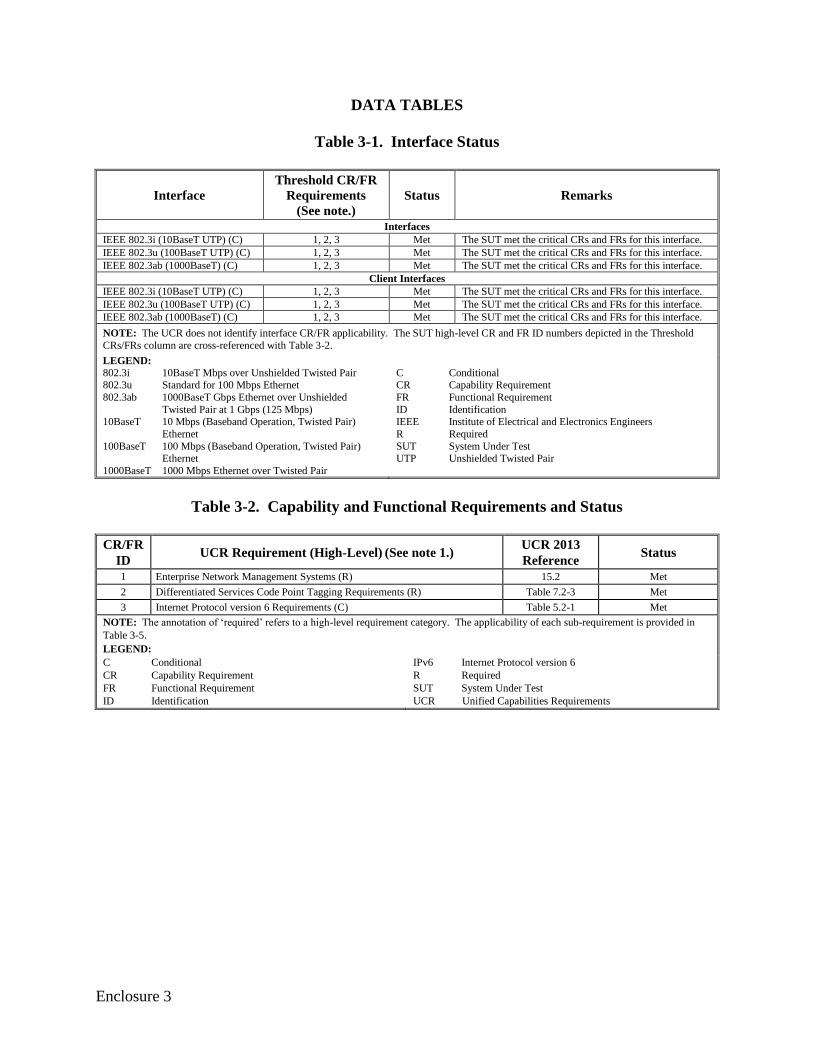
Approved Products List (APL). The SUT meets the interoperability requirements for the
interfaces listed in Table 3-1.
Enclosure 3
DATA TABLES
Table 3-1. Interface Status
Interface
Threshold CR/FR
Requirements
(See note.)
Status Remarks
Interfaces
IEEE 802.3i (10BaseT UTP) (C) 1, 2, 3 Met The SUT met the critical CRs and FRs for this interface.
IEEE 802.3u (100BaseT UTP) (C) 1, 2, 3 Met The SUT met the critical CRs and FRs for this interface.
IEEE 802.3ab (1000BaseT) (C) 1, 2, 3 Met The SUT met the critical CRs and FRs for this interface. Client Interfaces
IEEE 802.3i (10BaseT UTP) (C) 1, 2, 3 Met The SUT met the critical CRs and FRs for this interface.
IEEE 802.3u (100BaseT UTP) (C) 1, 2, 3 Met The SUT met the critical CRs and FRs for this interface.
IEEE 802.3ab (1000BaseT) (C) 1, 2, 3 Met The SUT met the critical CRs and FRs for this interface. NOTE: The UCR does not identify interface CR/FR applicability. The SUT high-level CR and FR ID numbers depicted in the Threshold
CRs/FRs column are cross-referenced with Table 3-2.
LEGEND:
802.3i 10BaseT Mbps over Unshielded Twisted Pair 802.3u Standard for 100 Mbps Ethernet
Avaya CS2100 with AS5300 CS2100 Release SE09.1/AS5300 Release 3.0 MFSS
Cisco Unified Communications Manager Version 8.6 (1) LSC
Oracle AcmePacket 3820 Release 5 CX6.40M1 SBC
Cisco Catalyst 4506 15.05 Switch
LEGEND:
LSC Local Session Controller MFSS Multifunction Softswitch
SBC Session Border Controller SUT System Under Test
3-3
Table 3-5. EMS Capability/Functional Requirements
ID Requirement UCR Ref
(UCR 2013) LoC/T C/R
1 15.2 – EMS Requirements
1-1 Enterprise and network management systems must interoperate with UC products’ COTS Network Management (NM) interface/system for monitoring
and commanding the UC product.
15.2
EMS-000020 L/T R
1-2 Enterprise and network management systems must leverage COTS interface of UC products to be managed in a secure manner.
15.2 EMS-000030
L R
1-3 Enterprise and network management systems must be capable of exchanging
data with other network management systems for information sharing purposes.
15.2
EMS-000040 L R
1-4 The management system must have the capability to receive SNMPv3 traps
from a monitored product.
15.2.1
EMS-000050 L/T R
1-5 The management system must have the capability to send SNMP [Management
Information Base (MIB)] poll requests to a monitored product.
15.2.1
EMS-000060 L/T R
1-6 The management system must have the capability to collect and mediate Call Detail Records (CDRs) and IP Detail Records (IPDRs) from a monitored
product in a secure manner
15.2.1
EMS-000070 T R
1-7 The management system must have the capability to secure the connection
using Transport Layer Security (TLS).
15.2.1
EMS-000080 T R
1-8 The EMS must be capable of receiving and analyzing System Events. 15.2.2
EMS-000090 T R
1-9 The EMS must be capable of receiving and analyzing Security Events. 15.2.2
EMS-000100 T R
1-10 The EMS must be capable of receiving and analyzing Performance Events (5-
minute polls).
15.2.2
EMS-000110 T R
1-11 The EMS must be capable of receiving and analyzing Performance (15-minute
polls).
15.2.2
EMS-000120 T R
1-12 The EMS must be capable of receiving and analyzing CDRs. 15.2.2
EMS-000130 T R
2 Table 7.2-3 – DSCP Tagging Requirements
2-1
Products that support IP interfaces shall support the DSCP plan, as shown in
Table 7.2-3. Differentiated Services (DS) assignments shall be software configurable for the full range of six-bit values (0-63 Base10).
7.2.1
EDG-000160 T R
3 5.2 – IPv6 Requirements
3-1 If a EMS device supports IP interfaces, then the EMS may support the IPv6 requirements as defined for NA/SS in UCR Section 5, IPv6. Refer to Table 3-6.
Table 5.2-1 L C
LEGEND:
C Conditional
COTS Commercial Off-the-Shelf DSCP Differentiated Services Code Point
EMS Element Management System
ID Identification IP Internet Protocol
IPv6 Internet Protocol version 6
L LoC Item
LoC Letter(s) of Compliance
NA/SS Network Appliance/Simple Server R Required
SNMPv3 Simple Network Management Protocol version 3
T Test UC Unified Capabilities
UCR Unified Capabilities Requirements
3-4
Table 3-6. IPv6 Requirements
ID Requirement UCR Ref
(UCR 2013)
LoC/TP
ID EMS
5.2 – IPv6 Requirements
3-1 The product shall support dual IPv4 and IPv6 stacks as described in RFC 4213. 5.2.1
IP6-000010 L C
3-2 Dual-stack end points or Call Connection Agents (CCAs) shall be configured to
choose IPv4 over IPv6.
5.2.1
IP6-000020 L C
3-3
All nodes and interfaces that are “IPv6-capable” must be carefully configured
and verified that the IPv6 stack is disabled until it is deliberately enabled as part of a deliberate transition strategy. This includes the stateless autoconfiguration of
link-local addresses. Nodes with multiple network interfaces may need to be
separately configured per interface.
5.2.1
IP6-000030 L C
3-4
The system shall provide the same (or equivalent) functionality in IPv6 as in IPv4 consistent with the requirements in the UCR for its Approved Products List
(APL) category. NOTE: This requirement applies only to products that are
required to perform IPv6 functionality and the feature parity is limited to the functionality tested in accordance with the distributed test laboratory approved
test procedures for the category of the product.
5.2.1
IP6-000050 L C
3-5 The product shall support the IPv6 format as described in RFC 2460 and updated by RFC 5095.
5.2.1 IP6-000060
L C
3-6
The product shall support the transmission of IPv6 packets over Ethernet
networks using the frame format defined in RFC 2464. NOTE: This
requirement does not mandate that the remaining sections of RFC 2464 have to be implemented.
5.2.1
IP6-000070 L C
3-7 The product shall support a minimum MTU of 1280 bytes as described in
RFC 2460 and updated by RFC 5095.
5.2.1.1
IP6-000090 L C
3-8
If Path MTU Discovery is used and a “Packet Too Big” message is received requesting a next-hop MTU that is less than the IPv6 minimum link MTU, then
the product shall ignore the request for the smaller MTU and shall include a
fragment header in the packet.
5.2.1.1
IP6-000100 L C
3-9 The product shall not use the Flow Label field as described in RFC 2460. 5.2.1.2
IP6-000110 L C
3-10 The product shall be capable of setting the Flow Label field to zero when
originating a packet.
5.2.1.2
IP6-000120 L C
3-11 The product shall be capable of ignoring the Flow Label field when receiving
packets.
5.2.1.2
IP6-000140 L C
3-12 The product shall support the IPv6 Addressing Architecture as described in
RFC 4291.
5.2.1.3
IP6-000150 L C
3-13 The product shall support the IPv6 Scoped Address Architecture as described in
RFC 4007.
5.2.1.3
IP6-000160 L C
3-14 If a scoped address (RFC 4007) is used, then the product shall use a scope index value of zero when the default zone is intended.
5.2.1.3 IP6-000170
L C
3-15
If Dynamic Host Configuration Protocol (DHCP) is supported within an IPv6
environment, then it shall be implemented in accordance with the DHCP for IPv6 (DHCPv6) as described in RFC 3315.
5.2.1.4
IP6-000180 L C
3-16
If the product is a DHCPv6 client, then the product shall discard any messages
that contain options that are not allowed to appear in the received message type
(e.g., an Identity Association option in an Information-Request message).
5.2.1.4 IP6-000200
L C
3-17
If the product is a DHCPv6 client and the first retransmission timeout has elapsed since the client sent the Solicit message and the client has received an
Advertise message(s), but the Advertise message(s) does not have a preference
value of 255, then the client shall continue with a client-initiated message exchange by sending a Request message.
5.2.1.4 IP6-000220
L C
3-18
If the product is a DHCPv6 client and the DHCPv6 solicitation message
exchange fails, then it shall restart the reconfiguration process after receiving user input, system restart, attachment to a new link, a system configurable timer,
or a user defined external event occurs.
5.2.1.4 IP6-000230
L C
3-19
If the product is a DHCPv6 client and it sends an Information-Request message,
then it shall include a Client Identifier option to allow it to be authenticated to the DHCPv6 server.
5.2.1.4
IP6-000240 L C
3-5
Table 3-6. IPv6 Requirements (continued)
ID Requirement UCR Ref
(UCR 2013)
LoC/TP
ID EMS
3-20
If the product is a DHCPv6 client, then it shall perform duplicate address
detection upon receipt of an address from the DHCPv6 server before
transmitting packets using that address for itself.
5.2.1.4 IP6-000250
L C
3-21 If the product is a DHCPv6 client, then it shall log all reconfigure events. NOTE: Some systems may not be able to log all this information (e.g., the
system may not have access to this information).
5.2.1.4
IP6-000260 L C
3-22 If the product supports DHCPv6 and uses authentication, then it shall discard
unauthenticated DHCPv6 messages from UC products and log the event.
5.2.1.4
IP6-000270 L C
3-23 The product shall support Neighbor Discovery for IPv6 as described in
RFC 4861.
5.2.1.5
IP6-000280 L C
3-24
The product shall not set the override flag bit in the Neighbor Advertisement
message for solicited advertisements for any cast addresses or solicited proxy advertisements.
5.2.1.5
IP6-000300 L C
3-25
When a valid “Neighbor Advertisement” message is received by the product and
the product neighbor cache does not contain the target’s entry, the advertisement
shall be silently discarded.
5.2.1.5 IP6-000310
L C
3-26
When a valid “Neighbor Advertisement” message is received by the product and
the product neighbor cache entry is in the INCOMPLETE state when the
advertisement is received and the link layer has addresses and no target link-layer option is included, the product shall silently discard the received
advertisement.
5.2.1.5
IP6-000320 L C
3-27 When address resolution fails on a neighboring address, the entry shall be
deleted from the product’s neighbor cache.
5.2.1.5
IP6-000330 L C
3-28 The product shall support the ability to configure the product to ignore Redirect messages.
5.2.1.5.1 IP6-000340
L C
3-29 The product shall only accept Redirect messages from the same router as is
currently being used for that destination.
5.2.1.5.1
IP6-000350 L C
3-30 If “Redirect” messages are allowed, then the product shall update its destination cache in accordance with the validated Redirect message.
5.2.1.5.1 IP6-000360
L C
3-31 If the valid “Redirect” message is allowed and no entry exists in the destination
cache, then the product shall create an entry.
5.2.1.5.1
IP6-000370 L C
3-32 If redirects are supported, then the device shall support the ability to disable this
functionality.
5.2.1.5.1
IP6-000380 L C
3-33 The product shall prefer routers that are reachable over routers whose
reachability is suspect or unknown.
5.2.1.5.2
IP6-000400 L C
3-34
If the product supports stateless IP address autoconfiguration including those
provided for the commercial market, then the product shall support IPv6 Stateless Address Autoconfiguration (SLAAC) for interfaces supporting UC
functions in accordance with RFC 4862.
5.2.1.6 IP6-000420
L C
3-35
If the product supports IPv6 SLAAC, then the product shall have a configurable
parameter that allows the function to be enabled and disabled. Specifically, the product shall have a configurable parameter that allows the “managed address
configuration” flag and the “other stateful configuration” flag to always be set
and not perform stateless autoconfiguration.
5.2.1.6
IP6-000430 L C
3-36 If the product supports IPv6 SLAAC, then the product shall have the
configurable parameter set not to perform stateless autoconfiguration.
5.2.1.6
IP6-000440 L C
3-37
While nodes are not required to autoconfigure their addresses using SLAAC, all
IPv6 Nodes shall support link-local address configuration and Duplicate Address Detection (DAD) as specified in RFC 4862. In accordance with RFC 4862,
DAD shall be implemented and shall be on by default. Exceptions to the use of
DAD are noted in the following text.
5.2.1.6
IP6-000450 L R
3-38
A node MUST allow for autoconfiguration-related variable to be configured by system management for each multicast-capable interface to include
DupAddrDetectTransmits where a value of zero indicates that DAD is not
performed on tentative addresses as specified in RFC 4862.
5.2.1.6
IP6-000460 L R
3-39 The product shall support manual assignment of IPv6 addresses. 5.2.1.6
IP6-000470 L R
3-40 The product shall support the Internet Control Message Protocol (ICMP) for
IPv6 as described in RFC 4443.
5.2.1.7
IP6-000520 L R
3-6
Table 3-6. IPv6 Requirements (continued)
ID Requirement UCR Ref
(UCR 2013)
LoC/TP
ID EMS
3-41
The product shall support the capability to enable or disable the ability of the
product to generate a Destination Unreachable message in response to a packet
that cannot be delivered to its destination for reasons other than congestion.
5.2.1.7 IP6-000540
L R
3-42 The product shall support the enabling or disabling of the ability to send an Echo Reply message in response to an Echo Request message sent to an IPv6
multicast or anycast address.
5.2.1.7
IP6-000550 L R
3-43 The product shall validate ICMPv6 messages, using the information contained in
the payload, before acting on them.
5.2.1.7
IP6-000560 L R
3-44 The product shall support MLD as described in RFC 2710. 5.2.1.8
IP6-000680 L R
3-45 If the product uses IPSec, then the product shall be compatible with the Security
Architecture for the IPSec described in RFC 4301.
5.2.1.9
IP6-000690 L C
3-46 If RFC 4301 is supported, then the product shall not support the mixing of IPv4
and IPv6 in a SA.
5.2.1.9
IP6-000700 L C
3-47 If RFC 4301 is supported, then the product’s security association database
(SAD) cache shall have a method to uniquely identify a SAD entry.
5.2.1.9
IP6-000710 L C
3-48 If RFC 4301 is supported, then the product shall implement IPSec to operate with both integrity and confidentiality.
5.2.1.9 IP6-000720
L C
3-49
If RFC 4301 is supported, then the product shall be capable of enabling and
disabling the ability of the product to send an ICMP message informing the
sender that an outbound packet was discarded.
5.2.1.9 IP6-000730
L C
3-50 If an ICMP outbound packet message is allowed, then the product shall be
capable of rate limiting the transmission of ICMP responses.
5.2.1.9
IP6-000740 L C
3-51 If RFC 4301 is supported, then the system’s Security Policy Database (SPD)
shall have a nominal, final entry that discards anything unmatched.
5.2.1.9
IP6-000750 L C
3-52
If RFC 4301 is supported, and the product receives a packet that does not match any SPD cache entries, and the product determines it should be discarded, then
the product shall log the event and include the date/time, Security Parameter
Index (SPI) if available, IPSec protocol if available, source and destination of the packet, and any other selector values of the packet.
5.2.1.9 IP6-000760
L C
3-53
If RFC 4301 is supported, then the product should include a management control
to allow an administrator to enable or disable the ability of the product to send
an IKE notification of an INVALID_SELECTORS.
5.2.1.9 IP6-000770
L C
3-54 If RFC 4301 is supported, then the product shall support the ESP Protocol in
accordance with RFC 4303.
5.2.1.9
IP6-000780 L C
3-55 If RFC 4303 is supported, then the product shall be capable of enabling anti-
replay.
5.2.1.9
IP6-000790 L C
3-56
If RFC 4303 is supported, then the product shall check, as its first check, after a packet has been matched to its SA whether the packet contains a sequence
number that does not duplicate the sequence number of any other packet
received during the life of the security association.
5.2.1.9
IP6-000800 L C
3-57 If RFC 4301 is supported, then the product shall support IKEv1 as defined in
RFC 2409.
5.2.1.9
IP6-000810 L C
3-58
To prevent a Denial of Services (DoS) attack on the initiator of an IKE_SA, the
initiator shall accept multiple responses to its first message, treat each as potentially legitimate, respond to it, and then discard all the invalid half-open
connections when it receives a valid cryptographically protected response to any
one of its requests. Once a cryptographically valid response is received, all subsequent responses shall be ignored whether or not they are cryptographically
valid.
5.2.1.9 IP6-000820
L C
3-59
If RFC 4301 is supported, then the product shall support extensions to the
Internet IP Security Domain of Interpretation for the Internet Security Association and Key Management Protocol (ISAKMP) as defined in RFC 2407.
5.2.1.9
IP6-000830 L C
3-60 If RFC 4301 is supported, then the product shall support the ISAKMP as defined
in RFC 2408.
5.2.1.9
IP6-000840 L C
3-61 If the product supports the IPSec Authentication Header Mode, then the product shall support the IP Authentication Header (AH) as defined in RFC 4302.
5.2.1.9 IP6-000850
L C
3-62 If RFC 4301 is supported, then the product shall support manual keying of
IPSec.
5.2.1.9
IP6-000860 L C
3-63 If RFC 4301 is supported, then the product shall support the ESP and AH cryptographic algorithm implementation requirements as defined RFC 4835.
5.2.1.9 IP6-000870
L C
3-7
Table 3-6. IPv6 Requirements (continued)
ID Requirement UCR Ref
(UCR 2013)
LoC/TP
ID EMS
3-64 If RFC 4301 is supported, then the product shall support the IKEv1 security
algorithms as defined in RFC 4109.
5.2.1.9
IP6-000880 L C
3-65 If the product uses Uniform Resource Identifiers (URIs) in combination with
IPv6, then the product shall use the URI syntax described in RFC 3986.
5.2.1.10
IP6-000990 L C
3-66 If the product uses the Domain Name Service (DNS) resolver for IPv6 based queries, then the product shall conform to RFC 3596 for DNS queries.
5.2.1.10 IP6-001000
L C
3-67
For traffic engineering purposes, the bandwidth required per voice subscriber is
calculated to be 110.0 kbps (each direction) for each IPv6 call. This is based on G.711 (20 ms codec) with IP overhead (100 kbps) resulting in a 250-byte bearer
packet plus 10 kbps for signaling, Ethernet Interframe Gap, and the Secure Real-
Time Transport Control Protocol (SRTCP) overhead. Based on overhead bits included in the bandwidth calculations, vendor implementations may use
different calculations and hence arrive at slightly different numbers.
5.2.1.11 IP6-001010
L C
3-68 The product shall forward packets using the same IP version as the version in the
received packet.
5.2.1.12
IP6-001040 L C
3-69
When the product is establishing media streams from dual-stacked appliances for AS-SIP signaled sessions, the product shall use the Alternative Network
Address Type (ANAT) semantics for the Session Description Protocol (SDP) in
accordance with RFC 4091.
5.2.1.12
IP6-001050 L C
3-70
If the product is using AS-SIP, and the <addrtype> is IPv6, and the <connection-
address> is a unicast address, then the product shall support generation and
processing of unicast IPv6 addresses having the following formats:
x:x:x:x:x:x:x:x (where x is the hexadecimal values of the eight 16-bit pieces
of the address). Example: 1080:0:0:0:8:800:200C:417A.
x:x:x:x:x:x:d.d.d.d (where x is the hexadecimal values of the six high-order 16-bit pieces of the address, and d is the decimal values of the four low-order
8-bit pieces of the address (standard IPv4 representation). For example, 1080:0:0:0:8:800:116.23.135.22.
5.2.1.13 IP6-001060
L C
3-71
If the product is using AS-SIP, then the product shall support the generation and
processing of IPv6 unicast addresses using compressed zeros consistent with one
If the product is using AS-SIP, and the <addrtype> is IPv6, and the <connection-address> is a multicast group address (i.e., the two most significant hexadecimal
digits are FF), then the product shall support the generation and processing of
multicast IPv6 addresses having the same formats as the unicast IPv6 addresses.
5.2.1.13
IP6-001080 L C
3-73 If the product is using AS-SIP, and the <addrtype> is IPv6, then the product shall support the use of RFC 4566 for IPv6 in SDP as described in AS-SIP 2013,
Section 4, SIP Requirements for AS-SIP Signaling Appliances and AS-SIP EIs.
5.2.1.13
IP6-001090 L C
3-74
If the product is using AS-SIP, and the <addrtype> is IPv6, and the <connection-
address> is an IPv6 multicast group address, then the multicast connection address shall not have a Time To Live (TTL) value appended to the address as
IPv6 multicast does not use TTL scoping.
5.2.1.13 IP6-001100
L C
3-75
If the product is using AS-SIP, then the product shall support the processing of IPv6 multicast group addresses having the <number of address> field and may
support generating the <number of address> field. This field has the identical
format and operation as the IPv4 multicast group addresses.
5.2.1.13
IP6-001110 L C
3-76
The products shall support Differentiated Services as described in RFC 2474 for a voice and video stream in accordance with Section 2, Session Control
Products, and Section 6, Network Infrastructure End-to-End Performance, plain
text DSCP plan.
5.2.1.14
IP6-001150 L C
3-77 If the product acts as an IPv6 tunnel broker, then the product shall support the function as defined in RFC 3053.
5.2.1.14 IP6-001160
L C
3-8
Table 3-6. IPv6 Requirements (continued)
ID Requirement UCR Ref
(UCR 2013)
LoC/TP
ID EMS
3-78 If the EMS has an IP interface, then the EMS must be IPv6-capable. Use
guidance in Table 5.2-4 for NA/SS. Table 5.2-1 L C
3-79
RFC 2407 The Internet IP Security Domain of Interpretation for ISAKMP Table 5.2-4 L C
RFC 2408 Internet Security Association and Key Management Protocol
(ISAKMP) Table 5.2-4 L C
RFC 2409 The Internet Key Exchange (IKE) Table 5.2-4 L C
RFC 2460 Internet Protocol, Version 6 (IPv6) Specification Table 5.2-4 L C RFC 2464 Transmission of IPv6 Packets over Ethernet Networks Table 5.2-4 L C RFC 2474 Definition of the Differentiated Services Field (DS Field) in the
IPv4 and IPv6 Headers Table 5.2-4 L C
RFC 2710 Multicast Listener Discovery (MLD) for IPv6 Table 5.2-4 L C RFC 3053 IPv6 Tunnel Broker Table 5.2-4 L C
RFC 3315 Dynamic Host Configuration Protocol for IPv6 (DHCPv6) Table 5.2-4 L C
RFC 3596 DNS Extensions to Support IPv6 Table 5.2-4 L C
RFC 3986 Uniform Resource Identifier (URI): Generic Syntax Table 5.2-4 L C
RFC 4007 IPv6 Scoped Address Architecture Table 5.2-4 L C RFC 4091 The Alternative Network Address Types (ANAT) Semantics for
the Session Description Protocol (SDP) Grouping Framework Table 5.2-4 L C
RFC 4092 Usage of the Session Description Protocol (SDP) Alternative
Network Address Types (ANAT) Semantics in the Session
Initiation Protocol (SIP)
Table 5.2-4 L C
RFC 4109 Algorithms for Internet Key Exchange Version 1 (IKEv1) Table 5.2-4 L C RFC 4213 Basic Transition Mechanisms for IPv6 Hosts and Routers Table 5.2-4 L C RFC 4291 IP Version 6 Addressing Architecture Table 5.2-4 L C
RFC 4301 Security Architecture for the Internet Protocol Table 5.2-4 L C
RFC 4302 IP Authentication Header Table 5.2-4 L C
RFC 4303 IP Encapsulating Security Payload (ESP) Table 5.2-4 L C
RFC 4443 Internet Control Message Protocol (ICMPv6) for the Internet
Protocol Version 6 (IPv6) Specification Table 5.2-4 L C
RFC 4566 SDP: Session Description Protocol Table 5.2-4 L C
RFC 4835 Cryptographic Algorithm Implementation Requirements for
Encapsulating Security Payload (ESP) and Authentication Header
(AH)
Table 5.2-4 L C
RFC 4861 Neighbor Discovery for IP Version 6 (IPv6) Table 5.2-4 L C RFC 4862 IPv6 Stateless Address Autoconfiguration Table 5.2-4 L C RFC 5095 Deprecation of Type 0 Routing Headers in IPv6 Table 5.2-4 L C
LEGEND:
C Conditional
EMS Customer Premise Equipment
DoD Department of Defense
DSN Defense Switched Network
DTMF Dual Tone Multi Frequency
EIA Electronic Industries Alliance FCC Federal Communications Commission
GR Generic Requirement
ID Identification IEEE Institute of Electrical and Electronics Engineers
ITU International Telecommunication Union
L LoC Item
LoC Letter(s) of Compliance
LSSGR Local Access and Transport Area (LATA) Switching
Systems Generic Requirements
MLPP Multi-level Precedence and Preemption
R Required TIA Telecommunications Industry Association