79
© 2007 Weatherford. All rights reserved. Deliquification of Gas Well with Plunger Lift
© 2007 Weatherford. All rights reserved.
Deliquification of Gas Well with Plunger Lift

© 2007 Weatherford. All rights reserved.
Major Concepts
• Plunger lift is one of the top 2 ways to lift liquid loaded gas wells.
• Limited by GLR
– Old rule 300 scf/bbl/1000 feet requires ideal conditions.
– Better Rule Greater than 1000 scf/bbl/1000 feet or 700
m3/m3/1000m
• The higher the surface pressure, the more build pressure and GLR
you need especially above 250-300 psi (1600-2100 kPa).
• Solids are not plungers friends – the more sand/scale etc. the more
likely there will be problems.
• Deviation can be handled but there are limitations
– Must be below 60 Degrees if more than 3 degrees per 100 feet
the length of plunger must be limited.
1

© 2007 Weatherford. All rights reserved.
Reference Definition
• Conventional Plunger Lift – A plunger that requires shut in
time for the plunger to fall to bottom. Well builds pressure
during shut in time.
• Continuous Flow Plunger Lift – Typically bypass plungers with
a valve system that allows fall against flow. Also known as
Velocity Plunger Lift as it requires the gas velocity to lift the
plunger rather than a build pressure.
2

© 2007 Weatherford. All rights reserved.3
Liquid Loading- Loss of Gas Velocity Over Time
Decreasing Gas Rate with Decreasing Reservoir Pressure TIME
Well
Dead
Initial
Production
Unstable FlowStable Flow Stable FlowRATE
Surface Condition
Gas Velocity
Highest Velocity Lowest Velocity
© 2007 Weatherford. All rights reserved.4
Gravity
Gas Flow
Water Droplet
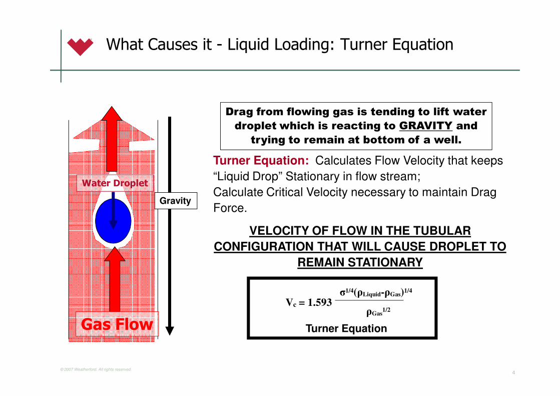
Drag from flowing gas is tending to lift water
droplet which is reacting to GRAVITY and
trying to remain at bottom of a well.
Turner Equation: Calculates Flow Velocity that keeps
“Liquid Drop” Stationary in flow stream;
Calculate Critical Velocity necessary to maintain Drag
Force.
VELOCITY OF FLOW IN THE TUBULAR
CONFIGURATION THAT WILL CAUSE DROPLET TO
REMAIN STATIONARY
Vc = 1.593σ1/4(ρLiquid-ρGas)1/4
ρGas1/2
Turner Equation
What Causes it - Liquid Loading: Turner Equation
© 2007 Weatherford. All rights reserved.5
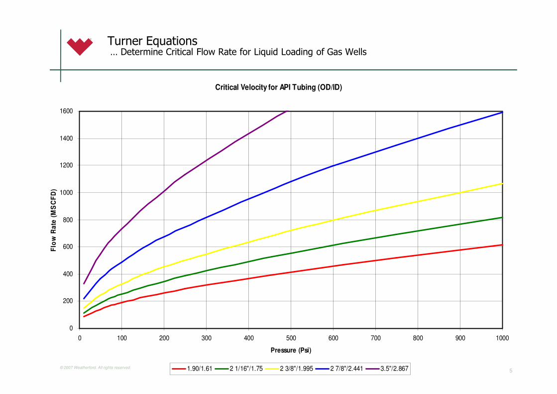
Turner Equations… Determine Critical Flow Rate for Liquid Loading of Gas Wells
Critical Velocity for API Tubing (OD/ID)
0
200
400
600
800
1000
1200
1400
1600
0 100 200 300 400 500 600 700 800 900 1000
Pressure (Psi)
Flo
w R
ate
(M
SC
FD
)
1.90/1.61 2 1/16"/1.75 2 3/8"/1.995 2 7/8"/2.441 3.5"/2.867

© 2006 Weatherford. All rights reserved.6
So Why do People Use Plungers?
© 2007 Weatherford. All rights reserved.7
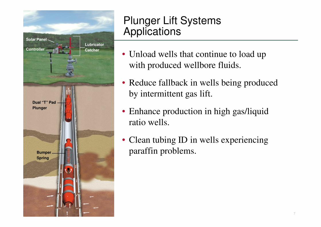
Plunger Lift SystemsApplications
• Unload wells that continue to load up
with produced wellbore fluids.
• Reduce fallback in wells being produced
by intermittent gas lift.
• Enhance production in high gas/liquid
ratio wells.
• Clean tubing ID in wells experiencing
paraffin problems.
Lubricator
Catcher
Solar Panel
Controller
Dual “T” Pad
Plunger
Bumper
Spring

© 2007 Weatherford. All rights reserved.8
Plunger LiftSystem Advantages
• Requires no outside energy source; uses well’s energy to lift
• Dewatering gas wells
• Rig not required for installation
• Easy maintenance
• Keeps well cleaned of paraffin deposits
• Low-cost artificial lift method
• Handles gassy wells
• Good in deviated wells
• Can produce well to depletion
Lubricator
Catcher
Solar Panel
Controller
Dual “T” Pad
Plunger
Bumper
Spring

© 2007 Weatherford. All rights reserved.9
Plunger LiftSystem Limitations
• Specific GLRs to drive system
– Around 700-1000 m3/m3/1000m
• Low-volume potential (30 m3/day of fluid)
• Major Solid Production
Lubricator
Catcher
Solar Panel
Controller
Dual “T” Pad
Plunger
Bumper
Spring

© 2007 Weatherford. All rights reserved.10

© 2006 Weatherford. All rights reserved.11
So Let’s Talk Evaluation of a Good Candidate
© 2007 Weatherford. All rights reserved.12
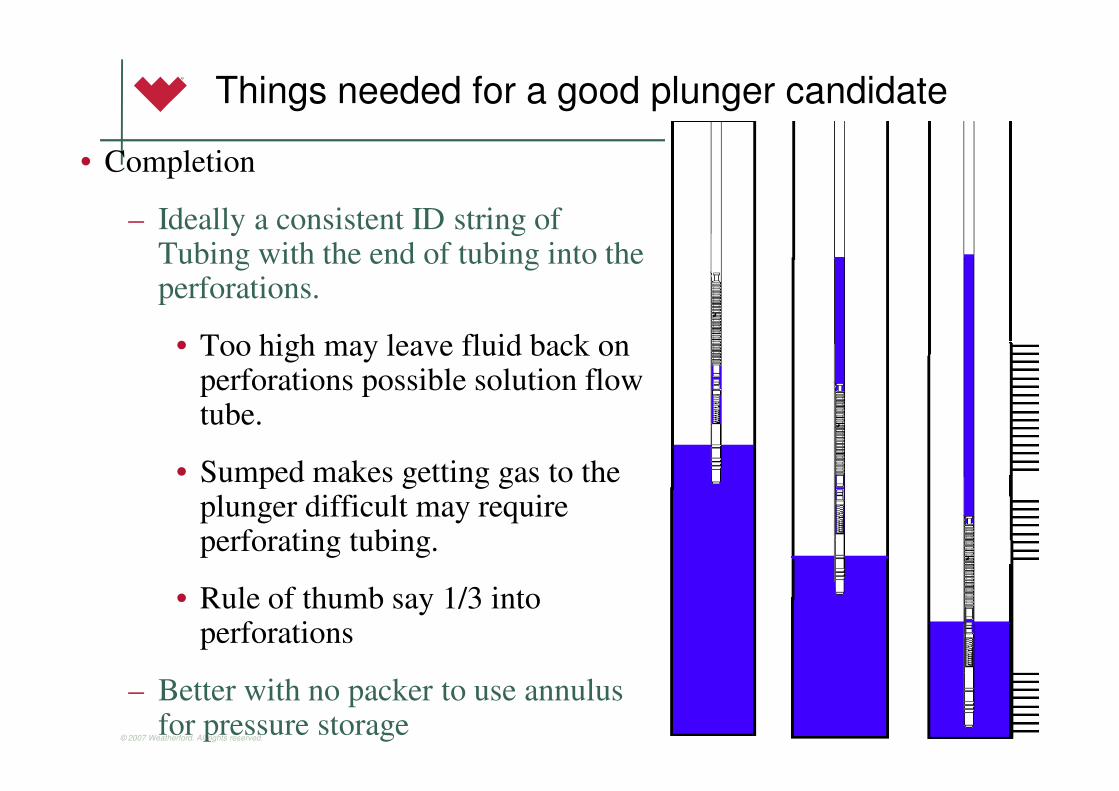
Things needed for a good plunger candidate
• Completion
– Ideally a consistent ID string of Tubing with the end of tubing into the perforations.
• Too high may leave fluid back on perforations possible solution flow tube.
• Sumped makes getting gas to the plunger difficult may require perforating tubing.
• Rule of thumb say 1/3 into perforations
– Better with no packer to use annulus for pressure storage

© 2007 Weatherford. All rights reserved.13
•Production Capability within range of plunger applicationThings needed for a good plunger candidate
Flowing Wellhead
Pressure <1600 kPa
or 250 psi
No Packer you will
need greater than 0.5
E3/m3/100m or 500
scf/bbl/1000 ft
Packer you need
greater than 1
E3/m3/1000m or 1000
scf/bbl/1000 ft
Flowing Wellhead
Pressure >1600 kPa
or 250 psi
No Packer you will
need greater than 1
E3/m3/1000m or
1000 scf/bbl/1000ft
Packer you need
greater than 2
E3/m3/1000m or
2000 scf/bbl/1000ft

© 2007 Weatherford. All rights reserved.14
•Production Capability within range of plunger application
•These production rates should be evaluated with a decline analysis to ensure liquid loading issues and potential uplift.
Things needed for a good plunger candidate

© 2007 Weatherford. All rights reserved.15
Things needed for a good plunger candidate
• Ability to achieve gas velocity by either
– The wells natural flow rates
• If a well can flow at over 3 m/s (10 ft/s) velocity but not
over critical it can seal a plunger (see next slide)
– Building Pressure
• If a well can’t flow over 3 m/s (10 Ft/s) velocity it will
require some shut in time to build pressure and achieve a
seal.

© 2007 Weatherford. All rights reserved.16
Things needed for a good plunger candidate
• Ability to achieve gas velocity by either
– The wells natural flow rates
© 2007 Weatherford. All rights reserved.17
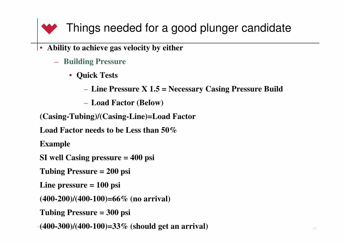
Things needed for a good plunger candidate
• Ability to achieve gas velocity by either
– Building Pressure
• Quick Tests
– Line Pressure X 1.5 = Necessary Casing Pressure Build
– Load Factor (Below)
(Casing-Tubing)/(Casing-Line)=Load Factor
Load Factor needs to be Less than 50%
Example
SI well Casing pressure = 400 psi
Tubing Pressure = 200 psi
Line pressure = 100 psi
(400-200)/(400-100)=66% (no arrival)
Tubing Pressure = 300 psi
(400-300)/(400-100)=33% (should get an arrival)

© 2007 Weatherford. All rights reserved.18
Things needed for a good plunger candidate
• Ability to achieve gas velocity by either
– Building Pressure
• Foss and Gaul (the hard way)
• Pcmin=Minimum Pressure Necessary to Cycle Plunger
• Pp = Pressure to lift weight of plunger.
• Plp = Flow-line pressure.
• Plw= Pressure to lift weight of liquid per barrel.
• Plf= Liquid frictional pressure loss per barrel.
• L = Load size, bbls
• D = Depth of tubing, ft
• K = Constant to show relationship between tubing size and pressure loses due to friction.
Pcmin=[(Pp + Plp + (Plw + Plf) x L) x (1 + (D/K))]

© 2007 Weatherford. All rights reserved.19
Things needed for a good plunger candidate
• Consistent Wellhead Size with Tubing Size
– Ideally 2 3/8” Tubing matched up with 2 1/16” Wellhead etc.
• Surface Facilities capable of High instantaneous rates and shut in
periods
• Minimal Sand and Solid Production

© 2007 Weatherford. All rights reserved.20
Things your service company needs to provide Initially
• Installation, line out and optimization.
• Equipment inspection, replacement, and scheduled
optimization.
• Complete Evaluations with solid technical expertise for
candidate selection assistance.
• Equipment material suitable for the conditions.
• Availability for training, service, and technical assistance on
the customers time line

© 2007 Weatherford. All rights reserved.21
Plunger Lift Equipment Overview
© 2007 Weatherford. All rights reserved.22
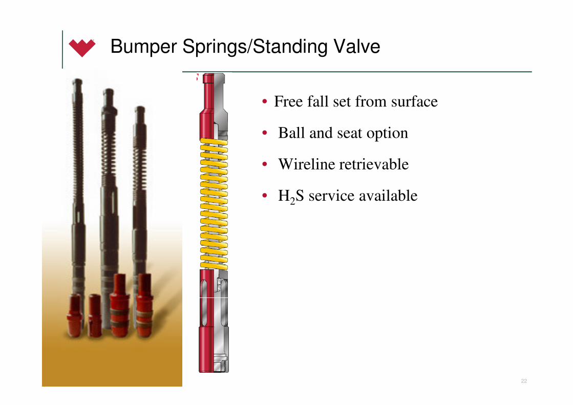
Bumper Springs/Standing Valve
• Free fall set from surface
• Ball and seat option
• Wireline retrievable
• H2S service available
© 2007 Weatherford. All rights reserved.23
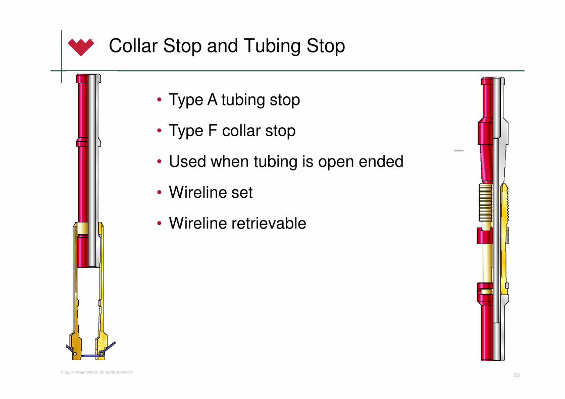
Collar Stop and Tubing Stop
• Type A tubing stop
• Type F collar stop
• Used when tubing is open ended
• Wireline set
• Wireline retrievable

© 2007 Weatherford. All rights reserved.24
Downhole Profile

© 2007 Weatherford. All rights reserved.
Surface Hookup
25
© 2007 Weatherford. All rights reserved.26
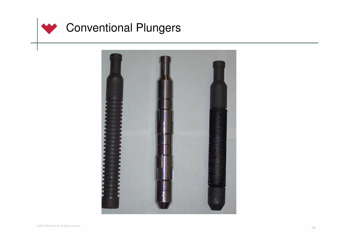
Conventional Plungers

© 2007 Weatherford. All rights reserved.27
Conventional Plungers
Description:
• Pad Plungers
– Metal/metal seal
– High efficiency, even
after cycling for months
• Brush Plungers
– Fiber seal
– Initially efficient seal
• Solid-Ring Plungers
– Turbulent seal
– Least-efficient seal
Applications:
• Pad Plungers
– Very low solid movement
(sand, scale)
– Maximum seal necessary to
move fluid
• Brush Plungers
– Sand movement
– Some cases necessary for efficiency
• Solid-Ring Plungers
– Scales application
– Dry-trip potential
– Poor monitoring in field
(no moving parts)

© 2007 Weatherford. All rights reserved.28
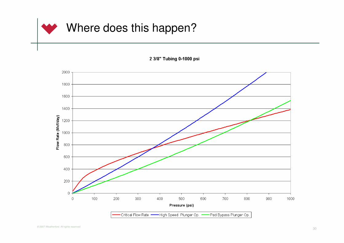
Life of a Plunger Well
A-Well Flowing Above Critical
B-Well flowing just below critical (High Speed Spiral Continuous Flow)
C-Well flowing below 5 m/s Padded Continuous Flow
D-Well flowing below 3 m/s Conventional
E-Low Reservoir pressure and inflow Seal very Important, consideration for Staging Plungerlift
© 2007 Weatherford. All rights reserved.29
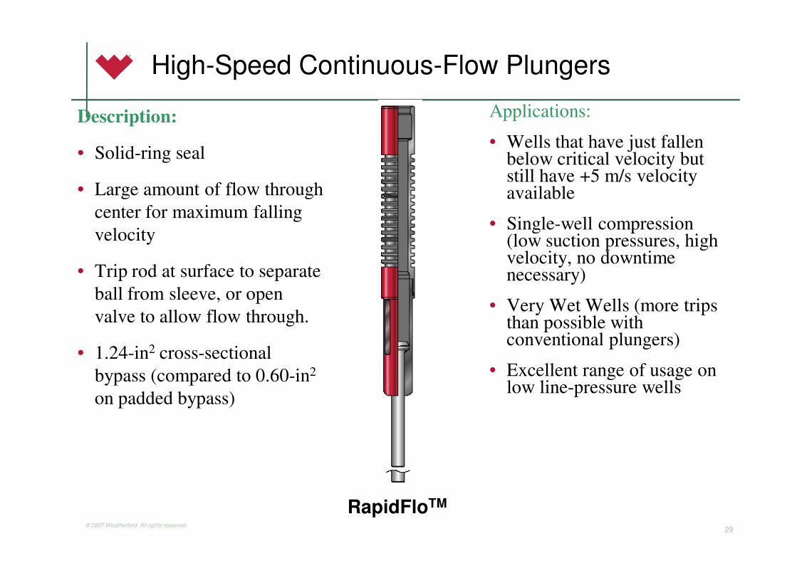
High-Speed Continuous-Flow Plungers
Description:
• Solid-ring seal
• Large amount of flow through
center for maximum falling
velocity
• Trip rod at surface to separate
ball from sleeve, or open
valve to allow flow through.
• 1.24-in2 cross-sectional
bypass (compared to 0.60-in2
on padded bypass)
Applications:
• Wells that have just fallen below critical velocity but still have +5 m/s velocity available
• Single-well compression (low suction pressures, high velocity, no downtime necessary)
• Very Wet Wells (more trips than possible with conventional plungers)
• Excellent range of usage on low line-pressure wells
RapidFloTM
© 2007 Weatherford. All rights reserved.30
Where does this happen?

© 2007 Weatherford. All rights reserved.31
Plunger Installation # 4: (installed 11-June)
0
50
100
150
200
250
300
350
400
4/2
4/2
004
5/1
/2004
5/8
/2004
5/1
5/2
004
5/2
2/2
004
5/2
9/2
004
6/5
/2004
6/1
2/2
004
6/1
9/2
004
6/2
6/2
004
7/3
/2004
mcfd
0
100
200
300
400
500
600
700
800
psig
well daily production
average mcfd pre-install
average mcfd post-install
casing pressure
Plunger Installation #4: (installed 11-June)
0
50
100
150
200
250
300
350
400
4/2
4/2
004
5/1
/2004
5/8
/2004
5/1
5/2
004
5/2
2/2
004
5/2
9/2
004
6/5
/2004
6/1
2/2
004
6/1
9/2
004
6/2
6/2
004
7/3
/2004
mcfd
0
15
30
45
60
barr
els
per day
daily fluid production wellhead mcfd

© 2007 Weatherford. All rights reserved.32
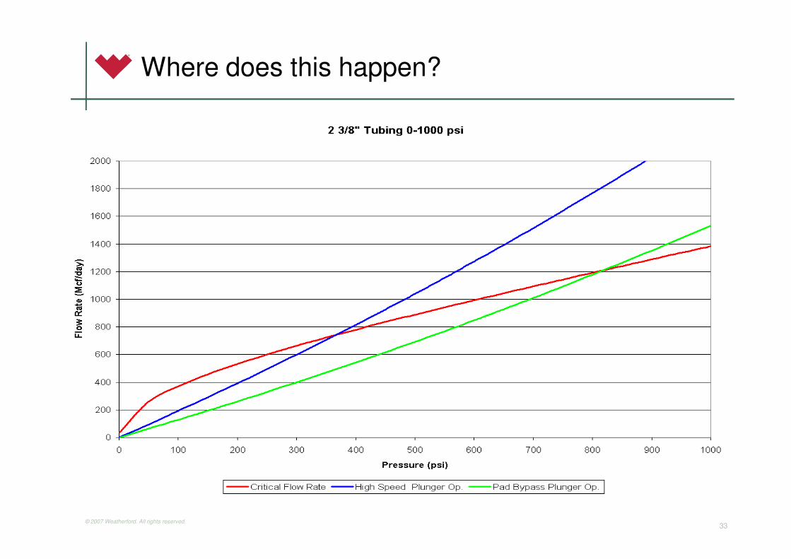
Padded/Brush Continuous-Flow Plungers
Description:
• Bypass-type plungers (allow flow through the plunger) with pad seal
• May have internal trip rod or trip rod in lubricator to trip valve
• 0.60-in2 cross-sectional bypass (compared to1.24-in2 on high-speed bypass)
Applications:
• 3-5 m/s velocities for continuous flow
• High fluid producers with quick build times for quick trip application
• Can be run at slightly higher line pressures than high speed plungers because of increased seal at lower velocities
© 2007 Weatherford. All rights reserved.33
Where does this happen?

© 2007 Weatherford. All rights reserved.34
Example of Application
Well successfully operating a conventional 2 3/8” Pad x Pad Plunger
to 350 psi line pressure however there appeared to be additional
gas production possible if well unloaded continually.
© 2007 Weatherford. All rights reserved.35
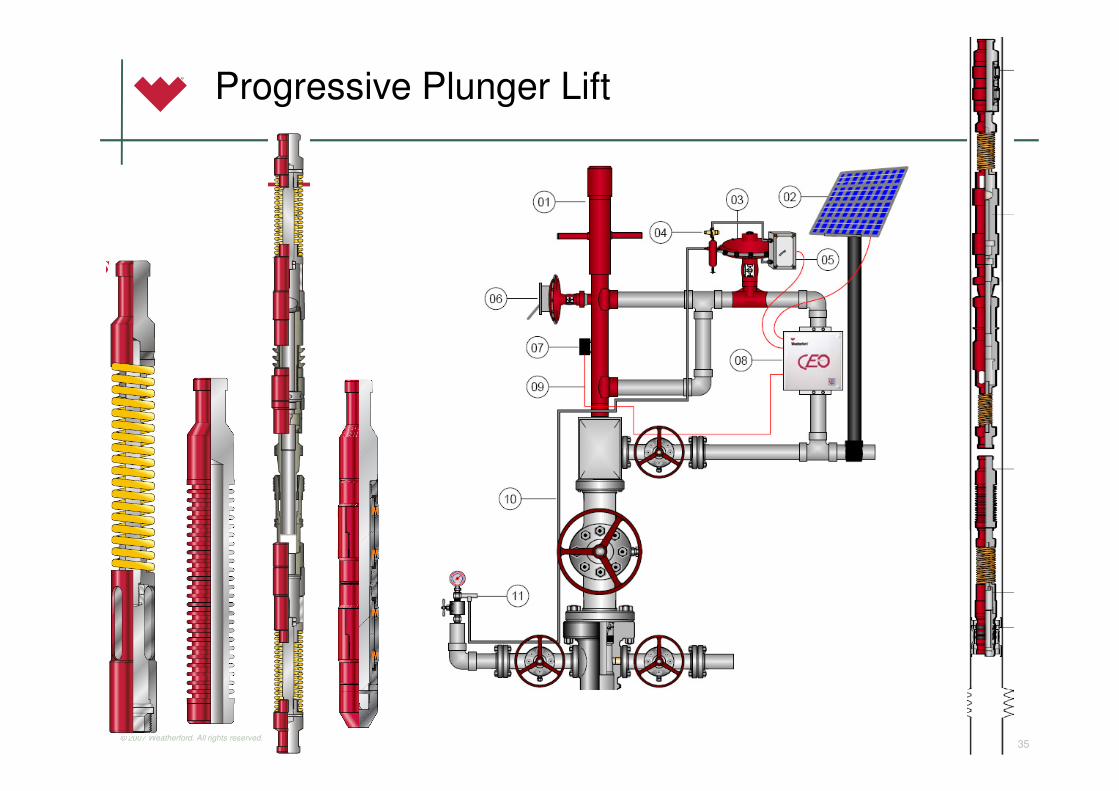
Progressive Plunger Lift

© 2007 Weatherford. All rights reserved.36
What is it?
• By adding an additional plunger in the tubing
string and “staging” the transfer of fluid the well
is produced in a more efficient manor.
• The system includes from bottom to surface
1. A typical bottom hole bumper spring
2. A solid ring plunger for the bottom stage
3. An ILA-Intermediate Landing Assembly
(see right) made up of two bumper springs
(one facing up/one down) a sealing
component, a check valve and a tubing stop.
4. Another plunger for the upper stage (usually
a double pad)
5. A Lubricator to receive the upper plunger.

© 2007 Weatherford. All rights reserved.37
Where is it Used (What makes a Good Candidate)
• Primarily used in wells that have GLR’s below what is
necessary to lift a conventional plunger.
• Generally wells that barely make the required gas for
lifting a plunger from bottom with the required fluid loads.
• Wells that shut in on arrival due to significant inflow of
fluid during lift cycle.
• Field Trials indicate that it decreases lift gas by 1-3 Mcf
per Barrel.
• Also used in wells which are depleted to the point that they
no longer can lift using available casing pressure builds.
• Wells that have previously been considered Rod Pump
Candidates.

© 2007 Weatherford. All rights reserved.38
Progressive Plunger System
Results
• More Cycles with less fluid per cycle resulting
in more total production.
• Well can keep up with fluid as it is delivered
from the formation.
• Casing Pressure is reduced therefore reducing
back pressure and increasing inflow.
• Well does not need to vent (all gas is produced
down sales line)
• Cycle’s are more regular
© 2007 Weatherford. All rights reserved.39
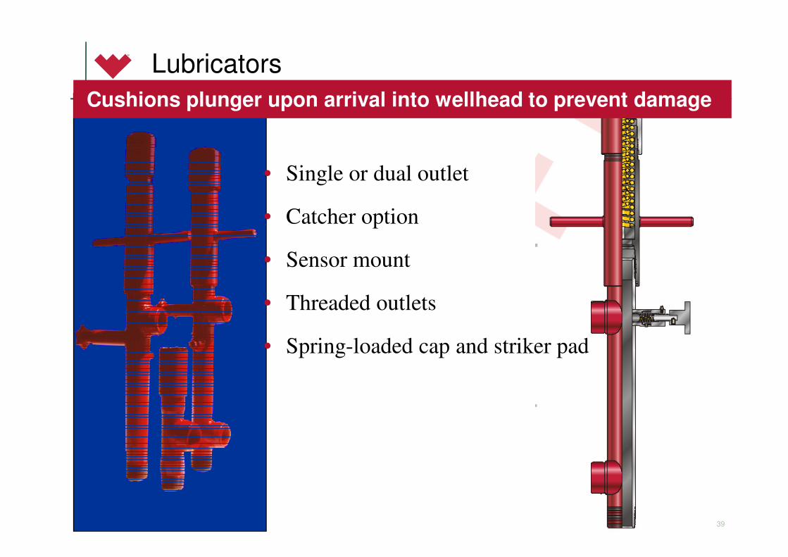
Lubricators
Cushions plunger upon arrival into wellhead to prevent damage
• Single or dual outlet
• Catcher option
• Sensor mount
• Threaded outlets
• Spring-loaded cap and striker pad

© 2007 Weatherford. All rights reserved.40
Accessories- Common between competitors
• Motor valves
• Sensor switch
• Solar panels
• Strap-on sensors
• Drip pot w/ regulators
• Control pilots
– Pressure reducing
– Differential control
• Gas filters
© 2007 Weatherford. All rights reserved.41
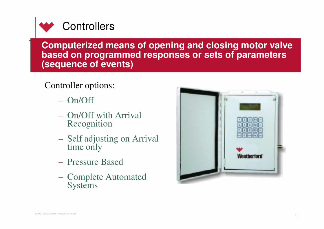
Controllers
Controller options:
– On/Off
– On/Off with Arrival Recognition
– Self adjusting on Arrival time only
– Pressure Based
– Complete Automated Systems
Computerized means of opening and closing motor valve based on programmed responses or sets of parameters (sequence of events)

© 2007 Weatherford. All rights reserved.42
History of Plunger Lift Control
Evolution of plunger lift control
– Time cycle control
» On time -- off time
– Time cycle with plunger arrival recognition
» On time -- sales time -- off time
– Auto-adjust time cycle
» Adjust time settings by reacting to failure
» Plunger traveling -- too fast, too slow, none– Pressure based Stand Alone control
» Operates on the pressure build of the well and on current
operating conditions optimizing every cycle based on the wells
capability and the systems capacity.
– Pressure based Auto-Adjust w/ Communications
» Central based communications provide-pressure based control as
well as adjustable settings from a central Host.

© 2007 Weatherford. All rights reserved.43
Different System’s
• Time Static Control – Changes are made only by operations, an optimization opportunity is recognized and changes are made directly to sales time or off time.
• Auto-Adjust – Changes are made based on previous plunger arrival time. Fast Arrivals = Less Off time, more sales time. Slow arrivals = More Off time, less sales time.
• Pressure Control
– Steady Pressures – Well cycles based on pre-set pressure conditions, well optimizes based on live well conditions. Changes to set pressures are made by operations.

© 2007 Weatherford. All rights reserved.44
CEO II Controller (Simple On/Off High Low)
• This controller can be used as our
On/Off Controller with On, Off, Sales,
Plunger Fall and Shut-In settings.
• Also used as a High/Low Controller
• The upgrade for this controller also
has an Auto-Tune Feature (Next
Slide)

© 2007 Weatherford. All rights reserved.45
CEO II+ Auto Tune Option

© 2007 Weatherford. All rights reserved.46
Normal Plunger Cycle
Solenoid
opens Control
Valve
Solenoid
Closes
Control
Valve
Well
continues
Shut In,
Builds
Pressure
Plunger Arrives
A-On
Time
Sales or After-
Flow Time
Plunger
Fall Time
Off Time or
Shut In Time

© 2007 Weatherford. All rights reserved.47
Pressure Based Control
Controller Information
• 6 Analog Inputs (1-5V or 4-20 mA) Currently used for Tubing, Casing, Line, and Differential pressure as well as Temperature which can be used for optimization
• Digital Inputs (Plunger Arrival switch, Murphy switch, tank float switch etc.)
• Digital Outputs (3 currently used on pulse valve operation)
• Certified to Class 1 Div 2 Class A,B,C,D or non-hazardous location
• Communicates using RS-232 and 485 protocols
© 2007 Weatherford. All rights reserved.48
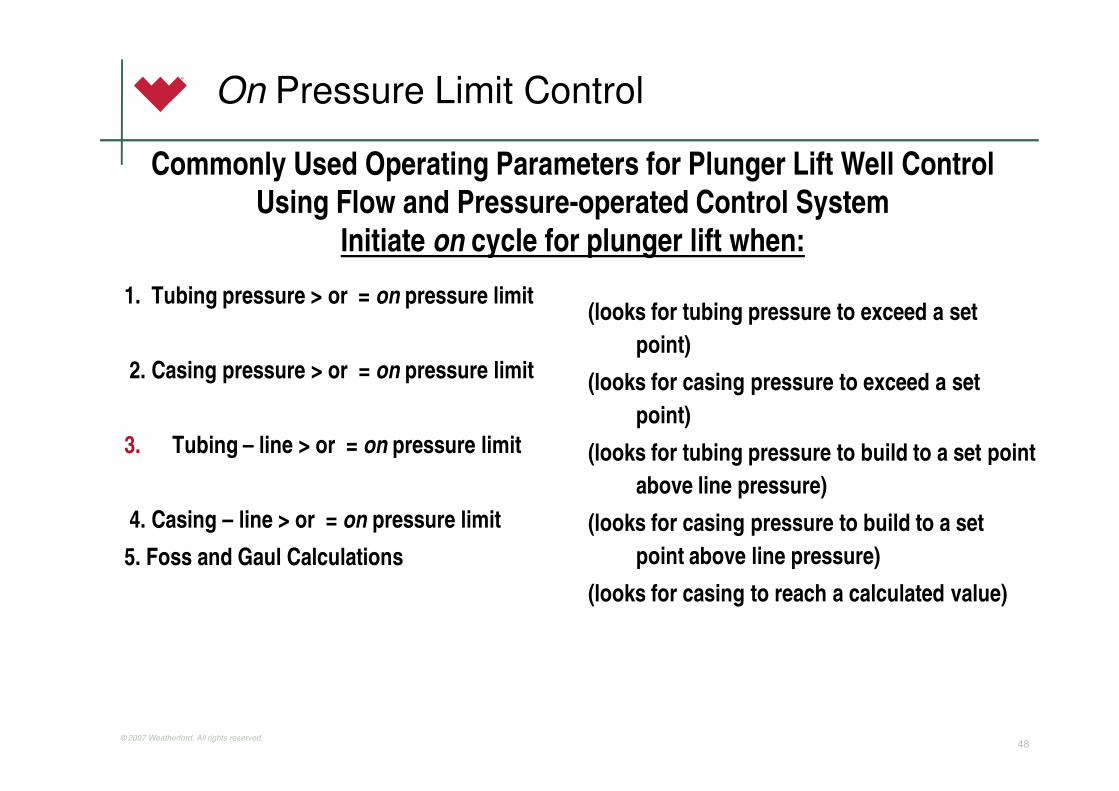
On Pressure Limit Control
1. Tubing pressure > or = on pressure limit
2. Casing pressure > or = on pressure limit
3. Tubing – line > or = on pressure limit
4. Casing – line > or = on pressure limit
5. Foss and Gaul Calculations
(looks for tubing pressure to exceed a set
point)
(looks for casing pressure to exceed a set
point)
(looks for tubing pressure to build to a set point
above line pressure)
(looks for casing pressure to build to a set
point above line pressure)
(looks for casing to reach a calculated value)
Commonly Used Operating Parameters for Plunger Lift Well Control
Using Flow and Pressure-operated Control System
Initiate on cycle for plunger lift when:

© 2007 Weatherford. All rights reserved.49
Off Pressure Limit Control
Initiate off cycle for plunger lift when:
1. Plunger has arrived (used on oil wells)
2. Casing pressure < or = off pressure limit (looks for casing to fall below a set pressure)
3. HW < or = off pressure limit (looks for flow rate to fall below a set differential ininches of water)
4. Flow Rate (Sometimes a calculated Turner Rate)
5. Casing-tubing > or = off pressure limit (looks for differential between casing andtubing to increase)
6. Casing To Tubing Sway looks for the casing and tubing pressure to start moving apart from each other.
7. Casing to Line > or = off pressure limit (looks for differential between casing and line pressure to increase)

© 2007 Weatherford. All rights reserved.50
Advance Pressure Controllers w/ Communication
Foss and Gaul Calculation
• A calculation in the controller to consistently perform a Foss
and Gaul calculation establishing the proper moment to kick
the well off.
– This calculation is a relationship accounting for fluid
load, surface pressure, casing size, tubing size, frictions
and depth.
– This calculation allows the opportunity to completely
compensate for changing line pressure as well as changes
in inflow.
© 2007 Weatherford. All rights reserved.51
Casing-Tubing Sway
Casing Sway Algorithm
– In order to completely optimize a casing-communicated
well that produces minimal fluid loads it is sometimes
necessary to flow the well below critical velocity until
fluid begins to accumulate to a point to where a
significant load has been achieved.

© 2007 Weatherford. All rights reserved.52
Casing-Tubing Sway
1. Identify Point where Casing
and Tubing get as close to
each other as possible.
2. Identify when they start to
move apart from each other.
3. Allow the pressures to move
a set amount apart to ensure
that the well can not unload
on it’s own again.
4. Shut in once the minimal
point plus the allowed sway
has been met.

© 2007 Weatherford. All rights reserved.53
Pressure based communicated devices
Controllers can be configured in the
field or from the central host

© 2007 Weatherford. All rights reserved.54
Equipment on WellEquipment on WellNew Technology forNew Technology forAnalyzing Plunger LiftAnalyzing Plunger Lift

© 2007 Weatherford. All rights reserved.55
Plunger Falling Through Gas & LiquidPlunger Falling Through Gas & Liquid
200 Ft/min
Gas
39 Ft/min
Liquid
Plunger Hits Liquid Plunger Hits Liquid
Plunger on Bottom Plunger on Bottom
Zoom in on Axis From 40.554 to 13 mins

© 2007 Weatherford. All rights reserved.56
Count Collars for Fall Velocity & DepthCount Collars for Fall Velocity & Depth

© 2007 Weatherford. All rights reserved.57
Plunger Depth and Fall VelocityPlunger Depth and Fall Velocity
Normally, Velocity Decreases as Plunger Falls Deeper into Well Normally, Velocity Decreases as Plunger Falls Deeper into Well
Begin Begin -- 250 ft/min250 ft/min
End End -- 131 ft/min131 ft/min
AXIS
Depth Axis

© 2007 Weatherford. All rights reserved.58
Evaluation
1. Establish decline curve (if well has ever flowed above critical).
2. Use the decline curve and any available pressure (casing, flowing gradients) to ensure that liquid loading is a problem.
3. Apply quick tests to establish if the well is a candidate using rule’s of thumb’s (spreadsheet).

© 2007 Weatherford. All rights reserved.59
Evaluation
4. Establish velocity (either calculate or use graphs)
• Use available velocity to establish whether well is a high speed continuous flow application (+15 ft/s or 5m/s), pad bypass application (10-15 ft/s or 3-5 m/s).
• If velocity is not available begin Foss and Gaul Calculations for Conventional Plunger lift (see next).
5. Foss and Gaul Evaluation for Conventional Plungerlift.
6. If well does not qualify for plungerlift review other forms of
artificial lift and compression.

© 2007 Weatherford. All rights reserved.60
Evaluation-Using Decline Curve and Pressure Data to Establish Loading.

© 2007 Weatherford. All rights reserved.61
Evaluation-Using Decline Curve and Pressure Data to Establish Loading.
Well Parameters
1) Flowing Casing pressure (if no
packer present)
2) Flowing Gradient Data and
Flowing Bottom Hole pressure.
3) LGR before liquid loading and
after.
What the parameters mean
1. Casing/Tubing differential usually indicates fluid in the tubing if the well is lower than the friction point.
2. Flowing gradient data can be used to figure out flow regimes and flowing bottom hole pressure can be used both in IPR calculation and liquid level calculation.
3. The LGR number can help establish what should be expected if the well was unloaded as well as the amount of fluid that needs to be moved to get the well unloaded.

© 2007 Weatherford. All rights reserved.62
Evaluation-Using Decline Curve and Pressure Data to Establish Loading.
4) Daily fluid and gas production.
5) Minute by minute gas
production.
6) Operator Input
4) Daily Fluid can give indication to erratic fluid
entry as well as well unloading itself. These
numbers need to be matched to daily gas to
establish which of the two it is.
5) Gives indication whether the well is sweeping
the chart or is consistently flowing. Used to
indicate flow regime.
6) Most important factor, Operator can tell you
what the well does and how it reacts and what
needs to be done to keep the well unloaded.

© 2007 Weatherford. All rights reserved.63
Quick Calculations to see if a well is a plunger candidate
Flowing Wellhead
Pressure <1600 kPa or
250 psi
No Packer you will need
greater than 0.5
E3/m3/100m or 500
scf/bbl/1000 ft
Packer you need greater
than 1 E3/m3/1000m or
1000 scf/bbl/1000 ft
Flowing Wellhead
Pressure >1600 kPa or
250 psi
No Packer you will need
greater than 1
E3/m3/1000m or 1000
scf/bbl/1000ft
Packer you need greater
than 2 E3/m3/1000m
or 2000 scf/bbl/1000ft

© 2007 Weatherford. All rights reserved.64
Pressures to see if a well will lift a plunger.
Load Factor
(Casing-Tubing)/(Casing-Line)=Load Factor
Load Factor needs to be Less than 50%
Example
SI well Casing pressure = 400 psi
Tubing Pressure = 200 psi
Line pressure = 100 psi
(400-200)/(400-100)=66% (no arrival)
Tubing Pressure = 300 psi
(400-300)/(400-100)=33% (should get an arrival)

© 2007 Weatherford. All rights reserved.65
Velocity Calculation
Velocity Equation from Turner (simplified)
2/1
4/1
)0031.0(
)0031.067(62.5)/(
P
Psfvcrit
−=
ZT
DPvmcfdV crit
)460(4
)12/(06.3)(
2/1
+
=π
P = pressure (psi)
D = wellbore diameter (inches)
T = temperature (Deg F)
Z = Z factor (dimensionless)

© 2007 Weatherford. All rights reserved.66
Velocity Using Graphs 2 3/8”

© 2007 Weatherford. All rights reserved.67
Velocity Using Graphs 2 3/8” (Metric)

© 2007 Weatherford. All rights reserved.68
Plot Result-Choose appropriate correlation

© 2007 Weatherford. All rights reserved.69
Results

© 2007 Weatherford. All rights reserved.70
Foss and Gaul Minimum Plunger Cycling Pressure Equation
• Pcmin=Minimum Pressure Necessary to Cycle Plunger
• Pp = Pressure to lift weight of plunger.
• Plp = Flow-line pressure.
• Plw= Pressure to lift weight of liquid per barrel.
• Plf= Liquid frictional pressure loss per barrel.
• L = Load size, bbls
• D = Depth of tubing, ft
• K = Constant to show relationship between tubing size and
pressure loses due to friction.
Pcmin=[(Pp + Plp + (Plw + Plf) x L) x (1 + (D/K))]

© 2007 Weatherford. All rights reserved.71
Weatherford Plunger Analysis Worksheet

© 2007 Weatherford. All rights reserved.72
Foss and Gaul Calculation
Parameters Example
2 3/8” Tubing set at 10000 ft with packer less completion in 4.5” casing
Produced with a LGR of 50 bbls/MMcf until it reach critical velocity.
Currently producing @ average of 20 Mcf/day however decline curve says well should produce @ 100 Mcf/day. Current fluid around 1 bbl/day mix oil and water.
Flowing to 100 psi line pressure Casing pressure fluctuates between 130 unloaded up to 360 loaded.
1 Hour SI when unloaded. Builds from 130 to 300 psi.
Example Results
Decline shows the well should be
doing 100 Mcf/day using the
LGR from over critical we
should be making 5 bbls/fluid
day with that 100 along with
some extra for the time below
critical.
Foss and Gaul tells us that we can
unload ½ bbl per cycle with a
build up of 300 psi and we
should be able to run 20 times a
day initially to clean up and level
out at around 10 runs a day once
near wellbore is cleaned up.
© 2007 Weatherford. All rights reserved.73
Example Completion Parameter
Completion
2 3/8” Tubing to 10000 ft (3115 m) in 4.5” Casing
100 ft (31.1m) of perforations, tubing hung 30 ft (9.3 m) into
perforations
No Packer
Wellhead 2 1/16”
Perforations clear (no sand)
Tubing gauged @ 1.901” (48.92 mm)
Good Completion for Plungerlift

© 2007 Weatherford. All rights reserved.74
Example #1 Decline Curve

© 2007 Weatherford. All rights reserved.75
Example #1 Decline Curve Analyzed

© 2007 Weatherford. All rights reserved.76
Example Well #1 parameters
Imperial
Production Data (Current) Average
200 Mcf/day w/ 4 bbls of water and 4 bbls of oil per day. LGR of 40 bbls/MMcf producing to 100 psi line pressure.
Production Data (past)
500 Mcf/day w/ 12.5 bbls of water and 12.5 bbls of oil per day. LGR of 50 bbls/MMcf
Decline shows well should be at 250 Mcf/day w/ 6 bbls Water and 6 bbls oil.
Well will build from 150 psi to 400 on casing in 1 hour when unloaded. Tubing pressure to 300 psi
Operator must unload well when line swings and production drops. Well normally has around300-400 psi on casing.
Metric
Production Data (Current) Average
5.6 E3m3/day w/ 0.6 m3 of water and 0.6 m3 of oil per day. LGR of 0.2 m3/E3m3 producing to 690 kPa line pressure.
Production Data (past)
14 E3m3/day w/ 2 m3 of water and 2 m3 of oil per day. LGR of 0.29 m3/E3m3.
Decline shows well should be at 7 E3m3/day w/ 1 m3 of water and 1 of oil.
Well will build from 1034 kPa to 2800 kpa on casing in one hour when unloaded. Tubing pressure builds to 2068 kPa
Operator must unload well when line swings and production drops.

© 2007 Weatherford. All rights reserved.77
Quick Calculations
Flowing WHP below 1600 kPa
(7E3m3/2m3/3115m) = 1.12 which
is greater than the 0.5 rule.
Load factor (2800-2068)/(2800-
690)=33% which is less then 50%
good pressure build
• Flowing WHP below 250 psi
(200000 scf/8 bbls/10 *1000feet) =
2500 which is greater than the 500
minimum
• Load Factor (400-300)/(400-
100)=33% which is less than 50%
so a good pressure build.

© 2007 Weatherford. All rights reserved.78
Example #1 Velocity
Velocity calculation = 17 ft/s Velocity Calculation 5 m/s


