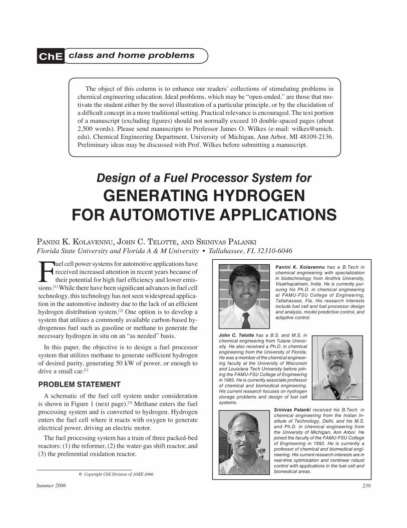
Panini K. Kolavennu has a B.Tech in chemical engineering with specialization in biotechnology from Andhra University, Visakhapatnam, India. He is currently pur-suing his Ph.D. in chemical engineering at FAMU-FSU College of Engineering, Tallahassee, Fla. His research interests include fuel cell and fuel processor design and analysis, model predictive control, and adaptive control.
John C. Telotte has a B.S. and M.S. in chemical engineering from Tulane Univer-sity. He also received a Ph.D. in chemical engineering from the University of Florida. He was a member of the chemical engineer-ing faculty at the University of Wisconsin and Louisiana Tech University before join-ing the FAMU-FSU College of Engineering in 1985. He is currently associate professor of chemical and biomedical engineering. His current research focuses on hydrogen storage problems and design of fuel cell systems.
Srinivas Palanki received his B.Tech. in chemical engineering from the Indian In-stitute of Technology, Delhi, and his M.S. and Ph.D. in chemical engineering from the University of Michigan, Ann Arbor. He joined the faculty of the FAMU-FSU College of Engineering in 1992. He is currently a professor of chemical and biomedical engi-neering. His current research interests are in real-time optimization and nonlinear robust control with applications in the fuel cell and biomedical areas.
Fuel cell power systems for automotive applications have received increased attention in recent years because of their potential for high fuel efficiency and lower emis-
sions.[1] While there have been significant advances in fuel cell technology, this technology has not seen widespread applica-tion in the automotive industry due to the lack of an efficient hydrogen distribution system.[2] One option is to develop a system that utilizes a commonly available carbon-based hy-drogenous fuel such as gasoline or methane to generate the necessary hydrogen in situ on an “as needed” basis.
In this paper, the objective is to design a fuel processor system that utilizes methane to generate sufficient hydrogen of desired purity, generating 50 kW of power, or enough to drive a small car.[1]
proBLem sTATemenT A schematic of the fuel cell system under consideration
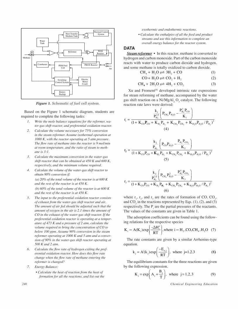
is shown in Figure 1 (next page).[3] Methane enters the fuel processing system and is converted to hydrogen. Hydrogen enters the fuel cell where it reacts with oxygen to generate electrical power, driving an electric motor.
The fuel processing system has a train of three packed-bed reactors: (1) the reformer, (2) the water-gas shift reactor, and (3) the preferential oxidation reactor.
Design of a Fuel Processor System for generATing hydrogen
for AUTomoTive AppLiCATionsPanini k. kolavennu, John c. telotte, and srinivas Palanki
Florida State University and Florida A & M University • Tallahassee, FL 32310-6046
Che class and home problems
The object of this column is to enhance our readers’ collections of stimulating problems in chemical engineering education. Ideal problems, which may be “open-ended,” are those that mo-tivate the student either by the novel illustration of a particular principle, or by the elucidation of a difficult concept in a more traditional setting. Practical relevance is encouraged. The text portion of a manuscript (excluding figures) should not normally exceed 10 double-spaced pages (about 2,500 words). Please send manuscripts to Professor James O. Wilkes (e-mail: [email protected]), Chemical Engineering Department, University of Michigan, Ann Arbor, MI 48109-2136. Preliminary ideas may be discussed with Prof. Wilkes before submitting a manuscript.
Based on the Figure 1 schematic diagram, students are required to complete the following tasks:
1. Write the mole balance equations for the reformer, wa-ter-gas shift reactor, and preferential oxidation reactor.
2. Calculate the volume necessary for 75% conversion in the steam reformer. Assume isothermal operation at 1000 K, with the reactor operating at 5 atm pressure. The flow rate of methane into the reactor is 9 mol/min at room temperature, and the ratio of steam to meth-ane is 3:1.
3. Calculate the maximum conversion in the water-gas shift reactor that can be obtained at 450 K and 600 K, respectively, and the minimum volume required.
4. Calculate the volume of the water-gas shift reactor to obtain 90% conversion if:
(a) 20% of the total volume of the reactor is at 600 K and the rest of the reactor is at 450 K.
(b) 60% of the total volume of the reactor is at 600 K and the rest of the reactor is at 450 K.
5. The input to the preferential oxidation reactor consists of exhaust from the water-gas shift reactor and air. The amount of air fed should be adjusted such that the amount of oxygen in the air is 2.1 times the amount of CO in the exhaust of the water-gas shift reactor. If the preferential oxidation reactor is operating at a temper-ature of 473 K and a pressure of 2 atm, calculate the volume required to bring the concentration of CO to below 100 ppm. Assume 90% conversion in the steam reformer operating at 1000 K and 5 atm and a conver-sion of 90% in the water-gas shift reactor operating at 500 K and 2 atm.
6. Calculate the flow rate of hydrogen exiting the pref-erential oxidation reactor. How does this flow rate change when the flow rate of methane entering the reformer is changed?
7. Energy Balance: • Calculate the heat of reaction from the heat of
formation for all the reactions, and list out the
exothermic and endothermic reactions. • Calculate the enthalpies of all the feed and product
streams and use this information to complete an overall energy balance for the reactor system.
dATA Steam reformer • In this reactor, methane is converted to
hydrogen and carbon monoxide. Part of the carbon monoxide reacts with water to produce carbon dioxide and hydrogen, and some methane is totally oxidized to carbon dioxide.
CH4 + ++ +
( ) ( )H O H CO
CO H O CO HCH
2 2
2 2 2
3 12
44 2 2 22 4 3+ + ( )H O H CO
Xu and Froment[4] developed intrinsic rate expressions for steam reforming of methane, accompanied by the water gas shift reaction on a Ni/MgAl2 O3 catalyst. The following reaction rate laws were derived:
r1 =−
+ (
.k
PP P
P PK
KH
CH H OH CO
CO
12 5
3
12
4 2
2
1 PP K P K P K P P
r
CO H H CH CH H O H O H+ + + / )
( )2 2 4 4 2 2 2
2
4
22
2
22
2
2 2
1=
−
+ +
(
kP
P PP P
KK P
HCO H O
H CO
CO CO KK P K P K P P
r
kP
H H CH CH H O H O H
H
2 2 4 4 2 2 2
2
2
3
33
5+ +
=
/ )( )
..
(
52
4
34 2
2 2
21
P PP P
KK P K P
CH H OH CO
CO CO H
−
+ + HH CH CH H O H O HK P K P P2 4 4 2 2 2
2
6+ + / )
( )
where r1, r2, and r3 are the rates of formation of CO, CO2, and CO2 in the reactions represented by Eqs. (1), (2), and (3) respectively. The Pi are the partial pressures of the reactants. The values of the constants are given in Table 1.
The adsorption coefficients can be found using the follow-ing relations for the respective species
K A K where i H COi i=
=( )exp , ,- H
RTio∆
2 ,, , ( )CH H O4 2 7
The rate constants are given by a similar Arrhenius-type equation.
k kj j
a j=−
A'ERT
where j=1,2,3 (8( )exp ,, ))
The equilibrium constants for the three reactions are given by the following expression,
KBT
where jjj= +
=exp A j , , , ( )1 2 3 9
WaterTank
Heat TransferMedium Tank
Thermal ControlSystem
Reformer WGSReactor
PROX ReactorPEM FuelCell
SwitchingControl System
Electric Motor(Load)
BatteryBackup
Combuster
Methane
Air
Figure 1
16
Figure 1. Schematic of fuel cell system.
Summer 2006 241
Water-gas shift reactor • In this reactor, most of the remaining carbon monoxide is converted to hydrogen. The following exothermic reaction occurs:
CO + +H O CO H2 2 2 10 ( )
Choi and Stenger[5] proposed a kinetic model for the water-gas shift reaction on a Cu/ZnO/Al2O3 catalyst operat-ing between 400 K to 700 K. The following rate law was developed.
r k P PP P
P P KCO H OCO H
CO H o eq4 4 2
2 2
2
1 11= −
( )
where r4 is the rate of formation of CO2 in the reaction repre-sented by Eq. (10). The equilibrium constant Keq varies with temperature as follows:
KTeq = −
exp . . ( )4577 8 4 33 12
The rate constant k4 follows an Arrhenius type equation as given below:
k A kERT
a4 4
4 13=−
'( ) exp ( ),
Other constant values used are given in Table 1. Preferential oxidation reactor • The stream exiting the
water-gas shift reactor may still have significant amounts of carbon monoxide that can poison the Polymer Electrolyte Membrane (PEM) fuel cell electrocatalyst. For this reason, it is necessary to have a preferential oxidation reactor where the carbon monoxide from the water-gas shift reactor is reacted with air to form carbon dioxide. Some of the hydrogen reacts with the oxygen to produce water.
CO O COH O H O
+
+
( / ) ( )( / ) ( )1 2 141 2 15
2 2
2 2 2
The following kinetic model was taken from Kahlich, et
al.[6]
r k PP
P
r k P
OO
CO
O
5 50 42
6 50 4
2
2
2
216
1 5
=
=
.
.
( )
. 22 2172
PP
O
CO
( )
where r5 represents the rate of formation of CO2 in the reaction represented by Eq. (16), and r6 represents the rate of forma-tion of H2O in the reaction represented by Eq. (17). The rate constant k5 follows an Arrhenius-type equation:
k A kERT
a5 5
5 18=−
'( ) exp ( ),
soLUTion Each reactor is modeled as an isothermal plug-flow reac-
tor. It is assumed that no axial mixing or axial heat transfer occurs. This implies that the reactors are operating at high
Peclet numbers for both heat and mass transfer. A more de-tailed analysis incorporating these diffusive effects has been conducted by Bell and Edgar.[7] The automotive application puts a constraint on the total volume of the reactor train, since the entire system has to fit under the hood. The design equations are solved numerically in MATLAB. The process is also simulated in the process simulator CHEMCAD. The results are given below.
mole Balance equations The general mole balance equation for a PFR is given by:
dFdV
rjj= ( )19
where j represents the species present in the reactor. It is necessary to determine the reaction rate for each species in the three reactors.
TABLE 1Kinetic Parameters for the Three Reactors
Parameter Value
A1 29.3014
A2 -4.35369
A3 25.225
A9 (k1 ) 9.88631016 [mol atm0.5/(m3 min)]
A9 (k2 ) 4.6653107 [mol atm−1/(m3 min)]
A9 (k3 ) 2.38631016 [mol atm0.5/(ltr min)]
A KH ( )
26.209310−9 [atm−1]
A(KCO) 8.339310−5 [atm−1]
A K OH ( )2
1.773105
A KCH ( )4
6.738310−4 [atm−1]
B1 -26248.4 [K−1]
B2 4593.17 [K−1]
B3 -21825.28 [K−1]
Ea,1 240.1 [kJ/(mol K)]
Ea,2 67.13 [kJ/(mol K)]
Ea,3 243.9 [kJ/(mol K)]
∆HH
O2
-82.90 [kJ/(mol K)]
∆HCOO -70.65 [kJ/(mol K)]
∆HH O
O2
+88.68 [kJ/(mol K)]
∆HCH
O4
-38.28 [kJ/(mol K)]
A9 (k4 ) 6.1953108 [mol atm−2/(m3 min)]
A9 (k5 ) 2.33331011 [mol atm−0.4/(ltr min)]
Ea,4 47.53 [kJ/(mol K)]
Ea,5 71 [kJ/(mol K)]
Chemical Engineering Education242
In the reformer, the reactions taking place are represented by Eq. (1)-(3). The reaction rates in terms of the species involved can be expressed in terms of the reaction rates represented by Eq. (4)-(6) as shown below.
r r rr r r
r r rr
CH
co
CO
4
2
1 3
1 2
2 3
202122
= − −
= −= +
( )( )( )
HH O
H
r r rr r r r
2
2
1 2 3
1 2 3
2 233 4 24
= − − −
= + +
( )( )
There is only one reaction occurring in the water-gas shift reaction as shown by Eq. (10). We can express the reaction rate of each Eq. (10) species in terms of the reaction rate of
Eq. (11) as follows: r rr rr rr r
CO
H O
CO
H
= −= −
=
=
4
4
4
4
25262728
2
2
2
( )( )( )( ))
In the preferential oxidation reactor, the reactions taking place are represented by Eq. (14)-(15). The reaction rates, in terms of the species, involved can be expressed in terms of the reaction rates represented by Eq. (16)-(17).
r r rr rr rr
O
CO
CO
2
2
0 5 0 5 293031
5 6
5
5
= − −
= −=
. . ( )( )( )
HH O
H
rr r
2
2
6
6
3233
=
= −
( )( )
volume of steam reformer
Rate expressions for the different reactions are given in terms of partial pressures of reacting species. The given mo-lar feed rate of the gases, Fj, should be converted to partial pressures. Using the molar feed rates, we can calculate the mole fraction of the feed used to calculate the partial pres-sures as follows:
XFF
P X P
jj
T
j j T
=
=
( )
( )
34
35
The partial pressure obtained is substituted into the rate expression to calculate the change in flow rate along the volume of the reactor.
1 2 3 4 5 6
0.1
0.2
0.3
0.4
0.5
0.6
0.7
Volume (liters)
Mo
le F
ract
ion
H2COCO2CH4H2O
1 2 3 4 5 6 7
Volume (liters)
0.8
0.7
0.6
0.5
0.4
0.3
0.2
0.1
00
H2CH4COCO
2H O
2
Conver
sion
(a) MATLAB (b) CHEMCAD
Figure 2
17
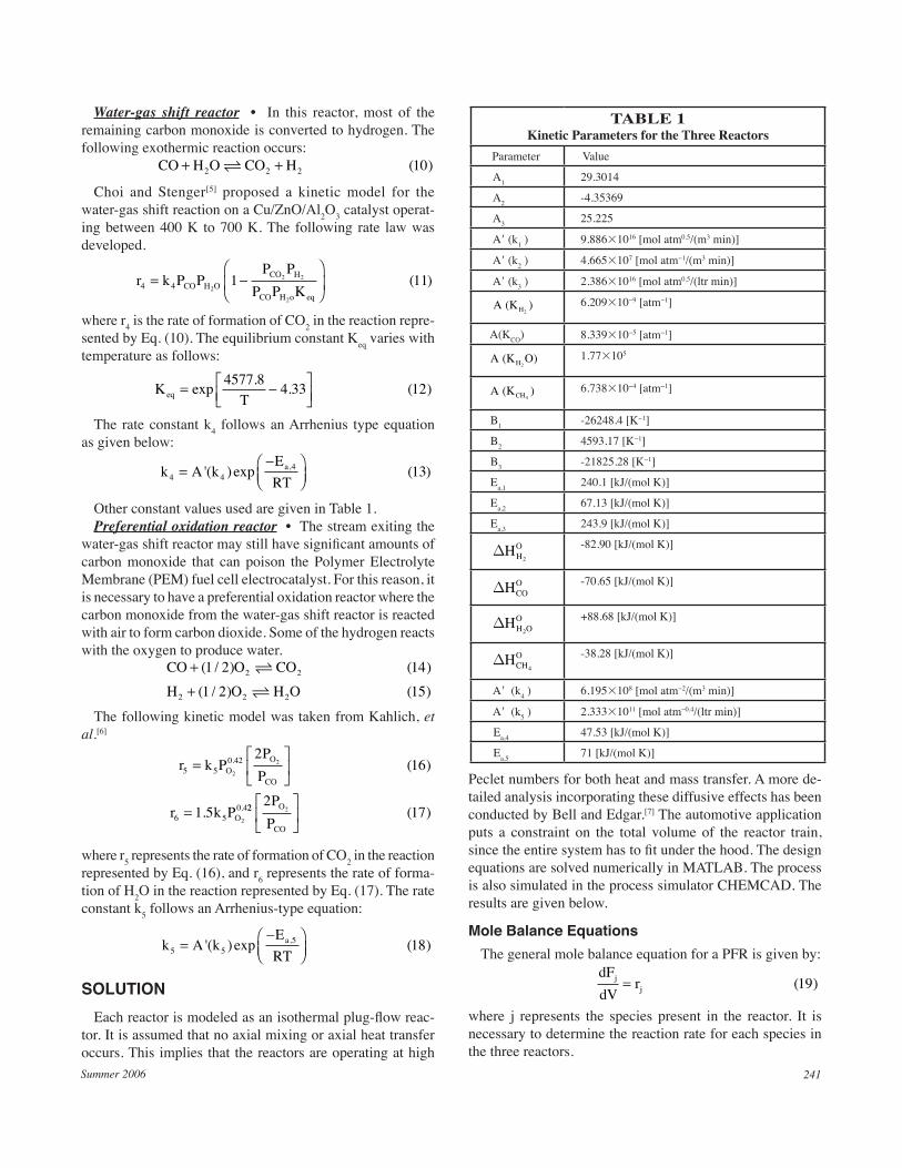
Figure 2. Concentration profiles in reformer.
0 50 100 150 200 2500
10
20
30
40
50
60
70
80
90
100
Volume (Liters)
Conver
sion
600 K
450 K
Figure 3
18
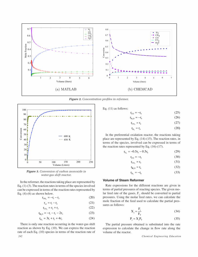
Figure 3. Conversion of carbon monoxide in water-gas shift reactor.
Summer 2006 243
the mole balance equations were integrated numerically for a variety of reactor volumes till the maximum conversion was attained. The conversion of carbon monoxide as a function of reactor volume at two different isothermal conditions (450 K and 600 K) is shown in Figure 3. If the reactor is operated isothermally at 450 K, the maximum conversion possible is
98.8%. The minimum volume required to obtain this conver-sion is about 250 liters. The maximum possible conversion at a temperature of 600 K is only 86.6%, and the minimum volume required is 9.4 liters.
volume of Two-Temperature-Zone Water-gas shift reactor
At low temperatures, the reaction is kinetically limited. At high temperatures, the reaction conversion is limited, i.e., the extent of reaction is limited by the thermodynamics. To mini-mize the volume, the reactor is operated at a high temperature (600 K), and to increase the conversion it is operated at a lower temperature (450 K). The reactor volume for 90% conversion under two different reactor temperature regimes is calculated in CHEMCAD, and verified with MATLAB. The results are shown in Table 2. It is observed that the reactor volume can be substantially reduced as compared to the isothermal operation if 20% of the reactor is operated at 600 K.
volume of preferential oxidation reactor The last reactor in the series is the preferential oxidation
reactor. Here, the concentration of CO is brought to less than 100 ppm. Along with the combustion of CO, some hydrogen is also burned. For the gases that have a 75% conversion in the reformer and a 90% conversion in the water-gas shift reactor, the amount of conversion in the preferential oxidation reactor (PROX) is approximately 98.7%. The volume obtained for this conversion is 0.335 liters.
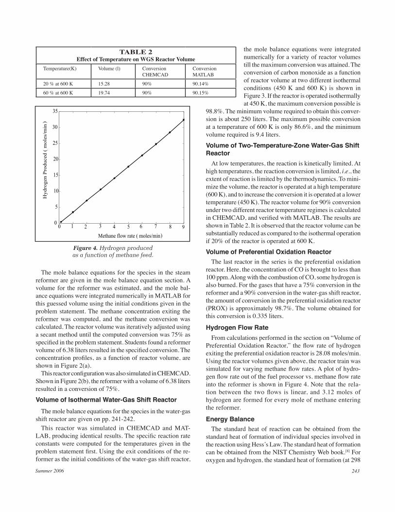
hydrogen flow rate From calculations performed in the section on “Volume of
Preferential Oxidation Reactor,” the flow rate of hydrogen exiting the preferential oxidation reactor is 28.08 moles/min. Using the reactor volumes given above, the reactor train was simulated for varying methane flow rates. A plot of hydro-gen flow rate out of the fuel processor vs. methane flow rate into the reformer is shown in Figure 4. Note that the rela-tion between the two flows is linear, and 3.12 moles of hydrogen are formed for every mole of methane entering the reformer.
energy Balance The standard heat of reaction can be obtained from the
standard heat of formation of individual species involved in the reaction using Hess’s Law. The standard heat of formation can be obtained from the NIST Chemistry Web book.[8] For oxygen and hydrogen, the standard heat of formation (at 298
TABLE 2Effect of Temperature on WGS Reactor Volume
Temperature(K) Volume (l) Conversion CHEMCAD
Conversion MATLAB
20 % at 600 K 15.28 90% 90.14%
60 % at 600 K 19.74 90% 90.15%
0 1 2 3 4 5 6 7 8 90
5
10
15
20
25
30
35
Methane flow rate ( moles/min )
Hydro
gen P
roduced (
mole
s/m
in)
Figure 1: Hydrogen Produced as a Function of Methane Feed
Figure 4
19
Figure 4. Hydrogen produced as a function of methane feed.
The mole balance equations for the species in the steam reformer are given in the mole balance equation section. A volume for the reformer was estimated, and the mole bal-ance equations were integrated numerically in MATLAB for this guessed volume using the initial conditions given in the problem statement. The methane concentration exiting the reformer was computed, and the methane conversion was calculated. The reactor volume was iteratively adjusted using a secant method until the computed conversion was 75% as specified in the problem statement. Students found a reformer volume of 6.38 liters resulted in the specified conversion. The concentration profiles, as a function of reactor volume, are shown in Figure 2(a).
This reactor configuration was also simulated in CHEMCAD. Shown in Figure 2(b), the reformer with a volume of 6.38 liters resulted in a conversion of 75%.
volume of isothermal Water-gas shift reactor The mole balance equations for the species in the water-gas
shift reactor are given on pp. 241-242. This reactor was simulated in CHEMCAD and MAT-
LAB, producing identical results. The specific reaction rate constants were computed for the temperatures given in the problem statement first. Using the exit conditions of the re-former as the initial conditions of the water-gas shift reactor,
Chemical Engineering Education244
K) is zero. The heat of formation for other species is given in Table 3. Using heat of formation data, the standard heats of reaction were found. These results are given in Table 4.
There are two feed streams going into the reactor train and one product stream coming out. The enthalpies of these streams can be computed easily in CHEMCAD. The enthalpy of the stream containing steam and methane is -8.261 MJ/min, the air stream is -0.003 MJ/min, and the product stream is -6.042 MJ/min. Air is assumed to be 79% nitrogen and 21% oxygen. Enthalpies are calculated based on the same reference states as those used for the heat of reaction. The net heat to be supplied to the fuel processor is 2.22 MJ/min.
disCUssion The purpose of this work was to demonstrate that standard
reaction engineering principles could be utilized to design a fuel processor that uses methane to generate hydrogen of the required purity for a PEM fuel cell used for automotive applications. The total volume required for the fuel processor to generate hydrogen of the required purity is small enough to fit under the hood of small cars. Furthermore, the energy bal-anced reactions involved indicate that there is a net depletion of energy, and so it is necessary to provide a small amount of heat to the reactors. This project gives the instructor the opportunity to discuss several reactor design issues such as:
• The importance of changing the temperature in the water-gas shift reactor to minimize the volume. This is a common approach when one looks at equilibrium limitations in exothermic reactions.
• The necessity of having the preferential oxidation reactor. While the reactor volume is small (the size of a soft drink can), it is necessary to have this reactor so that the concentration of carbon monoxide is reduced to a level
acceptable for the PEM fuel cell. • The importance of doing an overall energy balance on the
process. This exercise demonstrates it is necessary to burn some of the methane feed or the hydrogen generated for the reactions to proceed at the specified conditions.
• For every mole of methane utilized, more than 3 moles of hydrogen are produced. This demonstrates that hydrogen is produced not only from methane, but also from water.
• The equivalence of results in MATLAB and CHEMCAD for reactor design calculations.
This problem was given as a reactor design problem in our department in summer 2005. All design teams were ultimately successful in producing an acceptable design report for this problem. A discussion with the students at the end of the semester indicated a great deal of enthusiasm in tackling this problem. Students appreciated that a practical design problem had been assigned instead of a problem from a textbook.
All the reactor design calculations were done assuming steady state. In an automotive application, however, the de-mand for hydrogen will fluctuate, so it is necessary to compute the dynamic response of the reactor train to sudden changes in methane flow rate and utilize this information to design a suitable control system. This requires the solution of a set of partial differential equations,[7] and is beyond the scope of an undergraduate class in reaction kinetics.nomenCLATUre A (K) pre-exponential factor Ea Activation Energy, kJ/mol k rate constant K equilibrium constant or adsorption coefficient P partial pressure, Pascals r reaction rates, mol/min/l R gas constant, kJ/mol/K T temperature, K
referenCes 1. Zalc, J.M., and D.G. Loffler, “Fuel Processing for PEM Fuel Cells:
Transport and Kinetic Issues of System Design,” J. Power Sources, 111, 58-64 (2002)
2. Lovins, A.B., and B.D. Williams, “A Strategy for the Hydrogen Transi-tion,” 10th Annual U.S. Hydrogen Meeting, Vienna, VA (1999)
3. Kolavennu, P.K., J.C. Telotte, and S. Palanki, “Modeling and Control of a Fuel Cell Power System for Automotive Applications,” European Symposium for Computer Aided Process Engineering-14, Lisbon, Portugal (2004)
5. Choi, Y., and H.G. Stenger, “Water-Gas Shift Reaction Kinetics and Reactor Modeling for Fuel Cell Grade Hydrogen,” J. Power Sources, 124, 432-439 (2003)
6. Kahlich, M.J., H.A. Gasteiger, and R.J. Behm, “Kinetics of Selective CO Oxidation in H2-Rich Gas on Pt/Al2O3,” J. Catalysis, 171, 93-105 (1997)
7. Bell, N.H., and T.F. Edgar, “Modeling of a Fixed-Bed Water-Gas Shift Reactor,” J. Proc. Cont., 1, 22-31 (1991)
8. <http://webbook.nist.gov/chemistry/> 9. Larminie, J., and A. Dicks, Fuel Cell Systems, Wiley, New York (2000) p
TABLE 4 Standard Heats of Reaction and Type of Reaction


![Ocala Evening Star. (Ocala, Florida) 1903-02-16 [p ].ufdcimages.uflib.ufl.edu/UF/00/07/59/08/01260/00167.pdf · Sni-phur Family tendered Address tonight Newsom attended phlegm returned](https://static.documents.pub/doc/80x56/6080b631885e28132915c48e/ocala-evening-star-ocala-florida-1903-02-16-p-sni-phur-family-tendered-address.jpg)


![Ft. Pierce News. (Fort Pierce, Florida) 1911-07-21 [p ].ufdcimages.uflib.ufl.edu/UF/00/07/59/02/00167/01325.pdf · ping meaning Manilla hesitation Jacksonville Jacksonville addressed](https://static.documents.pub/doc/80x56/5e8ff5868a2b943c3b25f037/ft-pierce-news-fort-pierce-florida-1911-07-21-p-ping-meaning-manilla-hesitation.jpg)


