t t 1 DESIGN OF A HOSPITAL INFORMATION SYSTEM A project report by S M IQBAL Submitted to the Department of Computer Science and Engineering of Bangladesh University of Engineering and Technology, Dhaka in partial fulfilment of the requirements for the degree of POST - GRADUATE DIPLOMA IN COMPUTER SCIENCE & ENGINEERING under f' AIT - BUET PROGRAMME. January, 1990 ---- "_.~ 1111111111111111111111111111111111 : #76293# ~-7-------
Transcript
tt
1
DESIGN OF A HOSPITAL INFORMATION SYSTEM
A project report
by
S M IQBAL
Submitted to the Department of Computer Science and Engineering of Bangladesh University ofEngineering and Technology, Dhaka in partial fulfilment of the requirements for the degree
of
POST - GRADUATE DIPLOMA IN COMPUTER SCIENCE & ENGINEERING
under
f'
AIT - BUET PROGRAMME.
January, 1990
---- "_.~
1111111111111111111111111111111111 :#76293#
~-7-------
A project report
by
S M IQBAL
Approved as to style and contents by :
---~~~---(Dr Syed Mahbubur Rahman)Associate Professor & Head,Department of ComputerScience & Engineering.BUET.
,-M.~.- -----(Dr Md Shamsul Alam)Associate Professor,Department of ComputerScience & Engineering.BUET.
--~~----(Dr Ahmed Nurul Alam)
Head.Clinical Research Centre.
ICDDR,B.
Chairman(Supervisor)
Member
Member(V.C's Nominee)
.,
ABSTRACT
In designing a Hospital Informatlor System entity - relationship Is used and It Is extended. toInclude both structural and dynamic properties of data. The design process Is comprised of
two main steps - logical design and physical design. Behavior of entities of Hospital Informa-
t~on System was considered at the logical phase of the design. The Hospital Information
System Is designed to be Installed In microcomputer and Is Implemented In dBASE - IVjSQLprogram. As the system Is basically a file management system, each of the entitles and their
relationship is translated into a convenient dBASE - IVjSOL file under a single database. At thebeginning an opening menu helps the user to select various aspects of hospital activities. On
selection of Patient Admission it is possible to admit. a patient to a vacant bed. If InhousePatient care is selected monitoring of Patient's Condition, Medicare, Pathological condition and
Data entry for these are possible. In Administrative control mainly Duty schedules and Wardinformation is maintained. The program allows the users to process queries In SOL. The Inter-
active part of the system was Implemented In pure dBase and It has relieved the user fromlearning programming language for regular query processing & data entry. Reduction of paper
works to a considerable degree, expanding the span of control of the staff member of thehospital and thus minimizing the expenditure Is also a major attraction of the syslem.
ACKNOWLEDGEMENTSThe author wishes to express his gratitude to his adviser Dr. Syed Mahbubur Rahman
for patiently guiding and fully supporting him through all stages of work.
He also likes to express his heartlelt thanks to the following who have helped him duringthe production and writing of this work.
To Dr. Md. Shamsui Alam for being a member of the board of examiners and for hisvaluable suggestions and recommendations.
To Dr. Ahmed Nurul Alam of the Dhaka Hospital of International Centre for DiarrhoealDisease Research, Bangiadesh (ICDDR,B). Mr. Abdullah Hel Mostafa of Computer Information
Services of ICDDR,B and Dr. S.K. Roy of Clinical Sciences Division of iCDDR,B for their coop-eration and guidance for proper understanding of the activities concerned in the system.
To Dr. Md. Abdullah of National Institute of Preventive and SOcial Medicine (NIPSOM) forthe supply of some valuable data.
To Dr. Ahsanul Habib of Rajshahi University for his friendly help and cooperation.
To all his friends at AIT, BUET and ICDDR,B for. their encouragement and well wish.
To the UNDP for providing him with the financial support without which his studies wouldnot be possible.
CONTENTSCHAPTER - 1
INTRODUCTION
1.1 Beginning
.1.2 The Hospital Information System: An Overview
1.3 Statement of the Problem1.4 Objectives
1.5 Scope and Limitation1.6 Project Outline
1.7 Summary on Procedure Followed
CHAPTER - 2
REVIEW OF SYSTEM
2.1 Existing System Survey
2.2 Behavior Modeling
2.3 Trends and Problems of Logical Database Design
CHAPTER - 3
APPROACH TO DESIGN.
3.1 Design Step3.2 Design of the Logical System
3.2.1 Information Requirement Analysis:3.2.2 System Analysis and Specification
3.3 Design of. Physical System3.3.1 Configuration of Hardware
3.3.2 Choice of Programming Language3.3.3 Design of Input and Output
3.3.4 File Structure and Organization3.3.5 Development of Application Software3.4 Cost Benefit Analysis. 3.5 Implementation
Page no.
01
0102
0203
0303
03
05
05
0507
08
080808081012
1414
151515161717
CHAPTER - 4
LOGICAL SYSTEM DESIGN
4.1.1 Environment of the Hospital4.1.2 Requirement Analysis of the Hospital
4.1.3 Requirements of MHIS4.1.4'System Requirements4.1.5 Functional Specification4.2 System Analysis and Specification4.2.1 Decomposition4.2.2 Refinement
4.2.3 Ident~ication of Database Information.4.3 Structural Anaiysls
4.3.1 Identification of Entity and Relationship4.3.2 Drawing of ERDs
4.3.3 Identification of Attributes4.4 Behaviorai Anaiysis
4.4.1 instantiation of Entities4.4.2 Identification of User queries
4.4.3 Development of ERDBs4.5 Space Allocation for Data Stores
Page no.
19
192020202323232329293535
3535
43434346
CHAPTER-5 :
PHYSICAL SYSTEM DESIGN 51
5.1 Hardware Configuration 515.2 Language implementation 51
5.3 Collection of Data 52: ..
5.4 input / Output Design 52
5.5 File Design 59
CHAPTER - 6
BENEFIT ANALYSIS
6.1 Cost of System
6.2 Cost Benefit Analysis6.2.1 One Year Basis Costing without System
6.2.2 One Year Basis Costing with the System6.2.3 Comment on Cost Analysis
6.3 General Consideration
70
7071
72
737575
CHAPTER - 8
CONCLUSIONS
8.1 Discussion and Conclusions
8.2 Recommendations for Future Works
BIBLIOGRAPHY
80
8081
111
TABLES AND APPENDICES
. Table - 1Analysis of Data Stores
Table - 2
Data Space Allocation
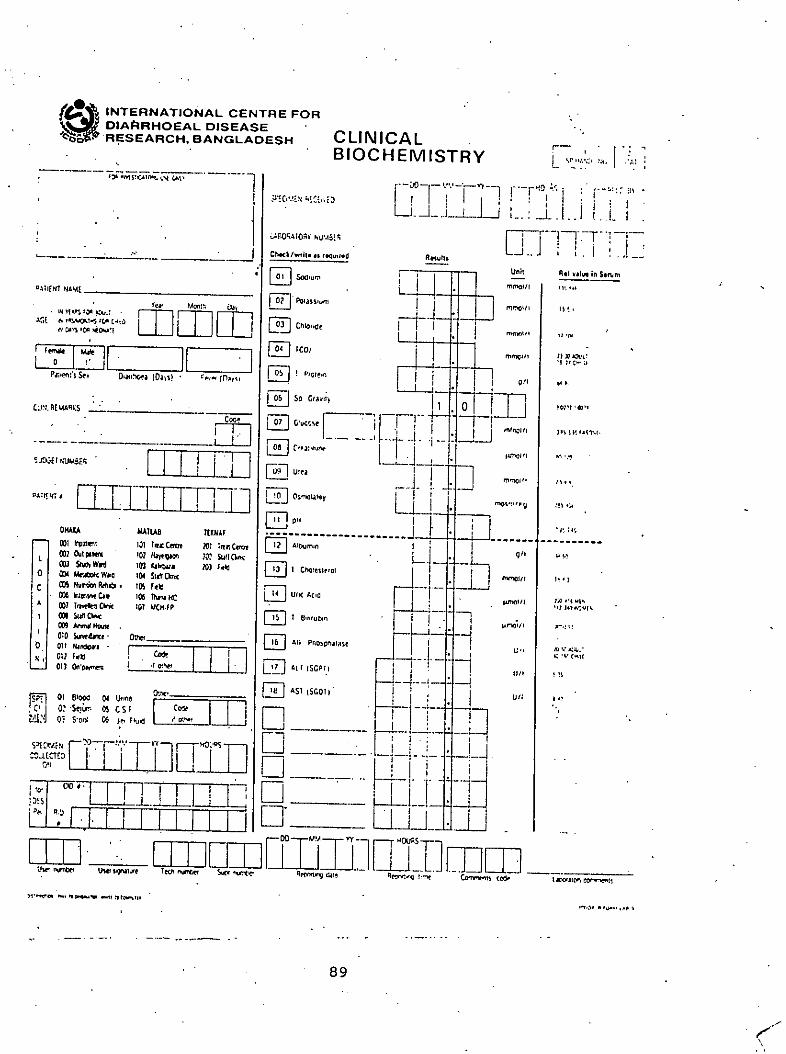
Appendix - AData Collection Forms
Appendix - B
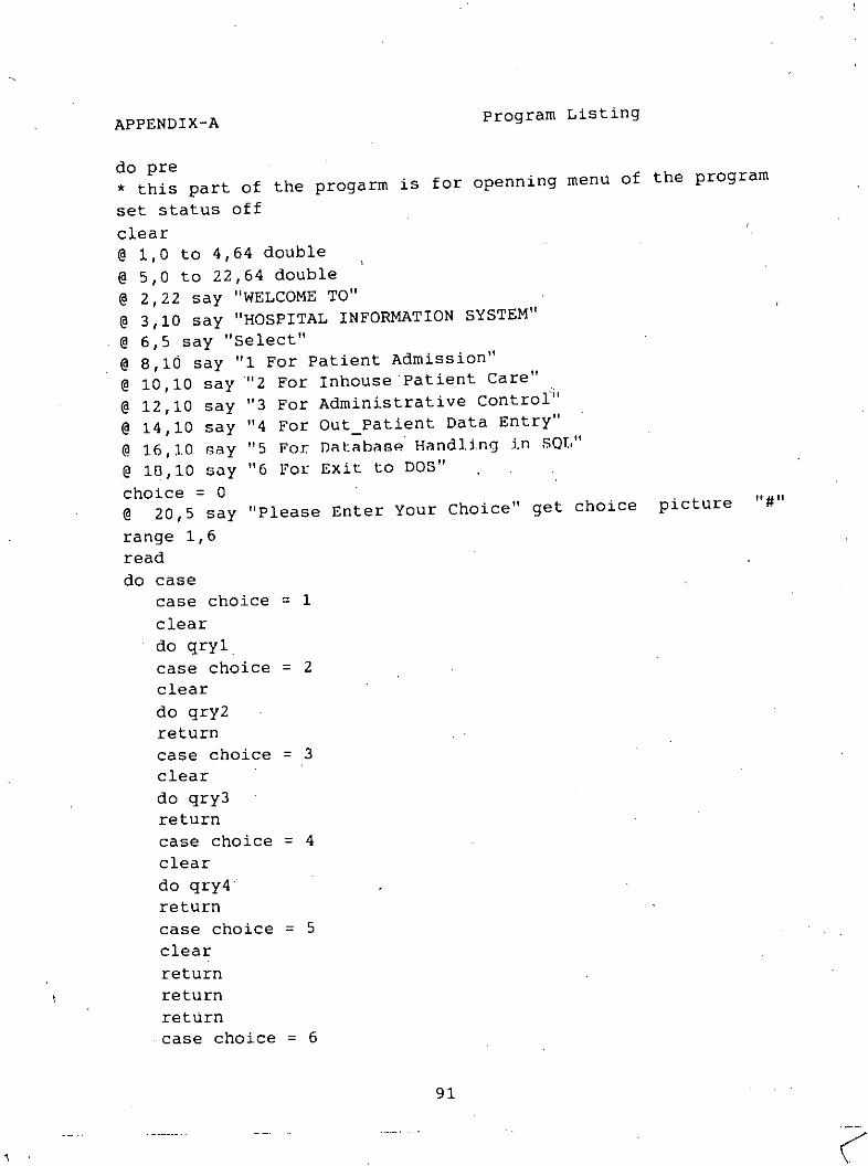
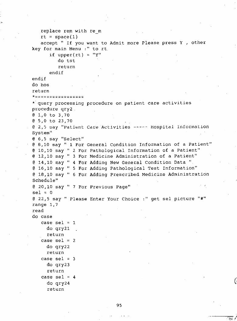
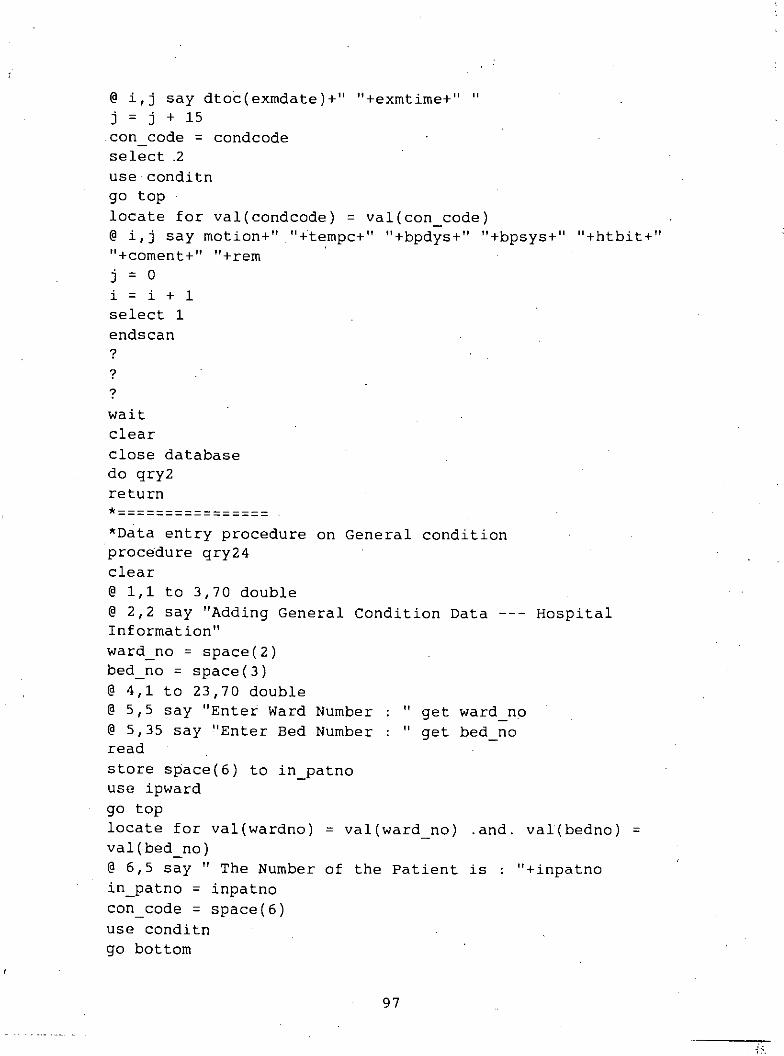
. Program Listing
Page no.
30
47
82
90
CHAPTER 1
INTRODUCTION
1.1 Beginning
Tho loglcol viow of lho dolo has boon an hllpOrlanl [ssuo In 1/10rocont yoa,". Tho bohavloralanalysis ur dola cunCOliiS IIsoli wllh on1/1/08. Wilon lhoso onl/I/os oxlsl, I/Ioy cllonyo h.1u dIs-
crete or continuous manner until such time that their existence [s lost. Th[ngs [n the realworld change over the time therefore a database systom must change accord[ngly. It is the
need to keep track of lhe dynamic nature of an entity which is oflen lhe prime molivation forIncluding it In a data processing system. The dynamic behavior of data has received little or
almost no attention In the past. As such previous work on system information modeling hadconcentrated almost exclusively on static view of the enterprise being modeled and thus [t wasrestricted to a time slice.
In recent times several approaches have b.een proposed for analysis and modeling of thebehavior of data. These models have their own strength and weakness: The network model
provides a more natural view of data by separating entities and relat[onships (to a certainextent). but -its capability to achieve data independence has been challenged. The relational
model is based on relational theory and can achieve a high degree of data independence, butit may lose some important semantic information about the real world. The hierarchicai (entity
set) model is the most natural view of data in the context of real world and provides highdegre~ of data independence and based on set theory. But its viewing may not be natural to
some peopie. The above models have used interaction oriented approach, wherein the interac-tion betWeen the application and the environment is described as well as the causes of
changes in the application, each used different representation techniques. The approach thathas been adopted In this project Is the extended entity relationship or EER data model. The
entity - relationship or ER model has the purpose of representing the real world in a pure andnatural way so that It is independent of storage and efficiency consideration (Chen, 1985).
The idea of this is to concentrate on the design of the conceptual schema - an intermediatestage in the logical design of a database.
The reai world environment is perceived and Is expressed in terms of entitles and relationshipsamong them. Thus an ER model is constructed using the three underlying concepts (a) enti-ties, (b) relationships, and (c) attributes. Entity is assumed to be a thing that exists throughperception and the enterprise to be modeled has interest on it. Reiationship describes how the-
entities are associated. Attribute describes character of an entity or it may be said as theproperty of an entity type.
ER approach in modeling of real world environment is very popular because it is very easy to
understand and easy to use. industries and research communities have been attracted to thesemantic expressiveness of this approach, because it is an effective tool between end - user
and database designers in specifying the user information requirements.
1
1.2 Tile liospllal Information System: An Overview
A medium sized hospital with a common organizational plan has been considered In the
project and Interest of the project Is concentrated on Its Information system.
Ideally It has a counter for Incoming patients where an Incoming patient can collect an outpa-t~ent slip to consult a doctor. As per the doctor's advice the patient may either take prescrip-
t~on and purchase medicines or report to inpatient counter and may seek admission. Thehospital has many beds organized in wards. Doctors and other hospital staff work in these
wards, The general physicians take full time care of the patients in ward whereas specialiststakes some round visits and specially prescribe medicine to the critical patient. General physi-
clans also prescribe medicine in case of emergency. Nurses administer medicine as perdoctor's advice. Pathological tests and X - Rays as advised by the physicians are carried
outside. But reports are subsequently received in the hospital .for later use. The hospital alsohave an administrative office which is responsible for doctor's duty schedule and control otherday to day activities.
This project choose the Dhaka Hospital of the International Center for Diarrhoeal DiseaseResearch, Bangladesh as its case study. This hospital is organized in different wards andhandle outpatients and inpatients and is basically the same as described above.
1.3 Statement of the Problem
The hospital employees have to manage a huge number of paper every day and thus havelittle time to take care of patients which make it difficult to ensure top quality service.
The Hospital Information System developed here will reduce repeatable paper works. The
nurses and doctors need not to search a huge bundle of papers in order to assess the condi-tion of a patient or to know about the dose of a drug or the time of its administration. Admin-
istrat~on of the hospital will be able to know the duty timing schedule. of the employees andtheir duty locations. Management of the patient will receive due attention if the system is
properly used. The information will be up to date and access to this information is possible
more easily and more accurately. Data retrieval for research and medico - legal purposes will
be faster and more dependable. Most important of all, the hospital services become more effec-t~ve because it can maintain its standard of quality and service.
This study is carried out to fill the need for a computerized information system for mediumsized hospitals.
Activities of a hospital change rapidly over any span of time of a day. New patients come in,get discharged, new tests on the patients are performed. Changes may also take place in
diagnosis or medicine administration. It is therefore necessary to anaiyze the dynamic structureof the data and model the data accordingly to its behavior in difference of time.
2,,
. ).;.
1.4 Objectives
Tho yonorol you I of Ihl~ projoct I~ 10 do~lgn and devolop a IllIGroGOrnpUlOrba~od Inlorlllulionsystem for medium sized hospital or large clinics. This may be called a Microcomputer - based
a) To design a medium sized hospital Information system by analyzing and modeling thebehavioral structure of data' within the hospital.
b) To translate the design Into executable program(s).
c) To translate some of the time to time interactive queries into executable programs.
d) To implement the MHIS in microcomputer.
1.5 Scope and Limitation
This study is limited to the following constraints:
a) Only outpatient consultation, inpatient admission, diagnosis,. medicine administration,
duty schedule, and personnel information of the hospital staff are included in the system.A limited number of queries and functions are Included.
b) Possible implementation is a medium sized hospital of 300 beds.
c) Consideration of storage and efficiency are excluded and beyond the scope of thepresent study.
d) Computer software and hardware facilities were limited to only those available at theBangladesh University of Engineering and Technology, Dhaka.
1.6 Project Outline
This project is organized as follows: Section 1 is already described. Section 2 presents the
description of available information system. Section 3 describes the design process of the EERapproach to system' analysis and design. Sections 4 and 5 discuss, respectively, the logical
and physical design of the system, with emphasis on the behavioral analysis during the logicalsystem design phase. Section 6 presents the benefit analysis of the system upon implementa-
tion. Section 7 is for implementation phase of the system. Section 8 presents the conclusionand directions for future work & research.
1.7 Summary on procedure followed
1) Survey of existing systems.
3
2) Study of present events going on in several hospitals - specially that of ICDDR,B.
3) Identification of usor's queries and requirements.
4) System study to deveiop DFDs.
5) Identifications of data stores from DFDs'.
6) Development of entity relationship diagrams in order to bridge the data stores and' todevelop relational model. Key or the prime indicators were also identified.
7) Space allocation for the attributes/fields of different data stores/entities.
8) Benefit analysis and proceedings for implementation.
9) Interactive program development.
a) The problem of vacant bed identified - the system takes care of it and reportto front desk of the hospital.
b) Patient care activities is the other area of probiem - the. system reports the
following things in order to ensure proper patient care. i) Pathological test reportssummary ii) Medicine Administration summary and special instructions iii) Conditionreports and diagnosis summary.
10) Development of user's manual on above functions.
11) Future study recommendation.
4
CHAPTER 2
REVIEW OF SYSTEM
2.1 Existing System Survey
The management system of patients in the hospitals here have their own shapes. which isquite different from the West. It is not easy t.o change the system within a very short period oftime. As such though there are very sophisticated and useful systems availabie in the de-ve~oped countries but Bangladesh being a developing one and has her own system so those
advanced hospital management oriented. information systems are not readily applicable here.'There Is no community based health system 'available here. So health services are restricted
only to some government hospitals and in the private sector. Because of this situation noHospital Information System has ever been developed or implemented. Though some hospitals
and clinics are using microcomputers for word processing and inventory control. This limitedcomputerization are In fact In little use for patient care activities directly and cannot be termedas. Hospital Information' System. The reason of this gap is mainly due to the non-availability 01
a suitably developed ready system.
The International Centre for Diarrhoeal Disease Research (ICDDR) is playing a pioneering role in
the computerization of health care activities in Bangladesh. But the organization Itself is dedi-cated to the research of a specific disease. Diarrhoea. so the iota I computerization of their
hospitals, does not come first. However. in ICDDR a demographic surveiliance system data-base is in use for various types research activities related to diarrhoeal disease. The informa-
tion system is using an IBM 4361 mainframe computer. The organization is also supporting aMCH - FP (Maternity Chiid Health and Family Planning) extension project using microcomputer
based system.
As mentioned earlier there is no global health care system in the country. The patients withtheir complains either go to the hospitals or consult a private practitioner with the cost exclu-
s~ve~yborne by themselves. -The hospitals in general run by the government or some charita-b~e organizations. Indoor patients of the hospitals are either referred cases of the outdoor or
patients entered through emergencies. Privately owned clinics are also providing health carefacilities. These clinics in general do not have outdoors and houses indoor patients only
referred by different private practitioners.
2.2 Behaviof.rvl0deling
Information systems have gained wide acceptance and applications so that we are now facedwith the problem of how to use these systems effectively. Several approaches and modelshave been designed to aid in the development of these information systems. The extension ofthe entity- relationship to aliow for behavior analysis and modeling had been discussed byseveral authors.
Jackson (1975) attempted to show how dynamic system models, as could be defined inSIMULA67, could be programmed in COBOL. This did not receive a great deal of attention
because it had been applied only to simple systems with a single entity type and no parallel-ism.
The work of Robinson (1979) developed a systems behavior modeling method using the tech-
01iqueof Jackson. He applied this to more realistic cases. The standpoint of his research wasthat the natural representation of a process such as an entity executing a behavior Is another
process. A process In the computer model was the execution of a program.
Tho language devolopod by Broutmann, Falkenborg, and Mauor (1070) hod tho option ofomboddlng lile dalllbase Instances Into lhe historical time axis. Based on tile time handling
facilities, . both the static properties and dynamic behavior of the conceptual schema instancescould be expressed.
A framework outlined by Bracchl, Furtado and Pelagatll (1979) specified and analyzed requIre-ments on the evolution of the database during its life cycle. The methodology was independ-ent of any specific data model or design method but emphasized on the importance of specIfy-
101gboth static and dynamic constraints. Two strategies for enforcing the static and dynamicconstraints were suggested - the first by specifying all transactions at the time of design and
the second by adding pre - programmed tests and actions to certain user requests.
Jones and Mason (1980) discussed the time dimension in relation to data modeling, updating,and the development of a user interface. They described the approach to the subject incorpo-rated In the legal system and language.
The Active and Passive Component Modeling (ACMjPCM) method for the design and specifica-tion of behavioral and structural properties of database transactions was presented by Brodie
(1981, 1984). ACMjPCM used the abstraction and localization (bottom- up) concepts. It wasbased on the concept that control structures (used for organizing programs) were the behavior-al counterpart of data structures (used for organizing data).
In defining the dynamic conceptual schema, Rolland (1983) Introduced an original giobal model.The model, called dynamic model, provided elements for construction of the conceptual control
of the relationships of time between data and programs. The concepts of objects, events, andoperations were Introduced and to represent the dynamic dimension of the real world, the rela-
tionsh~p between the concepts, namely, modify, induce, and trigger, were also introduced.
Sakai (1983) dealt on the analysis and modeling of the behavior of entities at the conceptuallevel. He introduced the notion of instantiation to analyze and modei the behavior of entities.
This behavior was defined as a set of transactions and states that results from transactions.
It was only until recently that there had been a surge of interest in temporal data, perhaps dueto the rapidly decreasing cost of memory and magnetic disk storage and the advances in
6
optical disk technology (Shoshani and Kawagoe, 1986). In the real world, business applicationssuch as banking, sales, inventory controi, and reservation systems need to maintain a complete
record of operations over the database. This history could be statistically analyzed for decisionmaking purposes. In their paper they developed a framework for the support of time se-
quences. The details of the design were not defined precisely.
Since this project was concerned more on the behavior of data during the design and analysisphase, the work of Sakal (1983a) seemed appropriate and has been adopted throughout thedesign process of the Microcomputer - based Hospital Information System.
2.3 Trends and Problems of Logical Database Design
Database design is a difficult task with all its complexities. It is also a time consuming proc-ess. If there is lack in usable database design methodology Inadequate database results
because they cannot satisfy present or future requirements of the organization. Although thereis a tremendous advancement of the sophistication of the applications of the database, the
development of techniques to support 111-designed database has not advanced comparably.
7
CHAPTER 3
APPROACH TO DESIGN
3.1 Design Steps
Having adopted the approach of Sakai. a two main step system design process is proposed:One is the design of the logical system. the other is the design of the physical system.
The logical system designs can be divided into 4 phases.
1) Information requirement analysis2) System analysis and specification
3) Structural analysis4) Behavioral analysis
3.2 Design of the Logical System
In the following subsection the basic principles of the design of logical system has been de-scribed in a nutshell. As mentioned earlier, It is of four phases.
3.2.1 Information Requirement Analysis
The requirement analysis phase Is concerned with documenting the organizational needs .andenumerating the means to satisfy these needs. It defines all the information to be used in the
ensuing system. Information requirements are usually obtained by interviewing people at var-ious levels of the organization, specially the users of the system. This stage delimits the scopeof the system and analyses Its activities. It is In this phase wherein the. environment andrequirements of the system are defined and the objectives of the system are specified.
The success of system development depends on how clearly the requirements are defined.
The fault of many designers is that information requirements are vaguely stated so that in theend, the system does not satisfy the needs of the organization it serves.
The organization that is of interest in the system is defined first. An organization may be of
any nature such as a bank, university, manufacturing plant or a hospital. The whole organiza-tion may be considered or selected division and department within the organization may beconsidered.
3.2.2 System Analysis and Specification
The purpose of the system anaiysis phase is to structure the requirements in order to produceworkable solutions to the problem at hand. The structuring of problem domain facilitates
problem solving process. The resulting structure becomes a model .of the problem. Systemanalysis was done using the structured analysis approach. The structured approach helps the
users and system developers to divide the large and complex problems Into smaller and slm-
8
pier problems that can be solved Independently.
The primary tool of tho structurod analysis is th~ data flow diagram (DFD). DF.D is a graphicaltool that represents data flow and transformations in a process. It provides an easy, graphicalmeans of modeling the flow of data through a system, whether it be manual, automated, or amixture of both. The components of DFD are:
a) Process or transforms, represented by circles or bubbles. Each process identifies a
function that transforms the data.
b) Data flow, represented by directed arrows. Arrows directed to a process are inputsto that process and arrows directed away from a process are outputs of that process.
Arrows to the database represent search argument and arrows from the databaserepresent retrieved information or status.
c) Sources or sinks of data, represented by rectangular boxes. The source shows
where the data required by the system comes from. It is a provider of data flows forthe system. The sink shows where the data produced by the system goes. It is areceiver of data flows from the system.
d) Data stores, represented by two horizontal parallel lines. A data store is a reposi-tory of data, e.g. files, graphics layout, etc.
The DFD techniques just show the flow of data in a system without emphasizing the physical
or control aspects. It does not indicate any timing consideration or sequence of events in thesystem, hence, it allows the designer to consider separately the logical anribute of the systemfrom the physical attributes. After a series of consultation with _the user, the user requirementsconcerning those parts which are automated are formalized into descriptions of data, tables,events, and constraints - - the result of which are represented by a DFD.
The system analysis and specification are done in four steps:
1) Decomposition2)" Refinements
3) Identification of database information4) Events description
3.2.2.1 Decomposition
In general the systems are usually large and complex to solve as one unit. It is necessary to
classify them into functional subsystems. The entire system is partitioned into smaller subsys-tems those are simple to specify concisely. Once these subsystems are identified, it "is possi-b~e to display the Information flow among them.
9
•
3.2.2.2 Refinements
A simple DFD is usually not enough to depict the flow of data among the different subsystems.Therefore, the DFD is refined in order to subdivide the task Into smaller subsystems producing
lower level DFDs, tile Information lIow In each sullsystem are clearly defined. and specified.
3.2.2.3 Database Information
.From the Information requirement in the DFDs it Is necessary to choose the data elements tobe included In the database. As some elements are better stored as external files or just
maintained as written document, the analysis of the Information to be stored in the database. should provide a database that really reflects the entitles, relationships, and data processing
needs of the community. It should be noted that in determining the elements for inclusion Inthe database, it must be Independent of any implementation approach.
3.2.2.4 Event Description
An event specification describes a change In the state of data elements to a point in timerelated to a specified happening In the enterprise. The state - changes are described in termsof their pre - conditions and post - conditions associated with each operation. State changes
are specified by sequence of actions called procedures, processes or functions. The descrip-tion of events at this early stage consists only of specifying actions at higher level abstract
operations .. It paves the way to an early understanding in the development of how the futuresystems operate In production .. The next phases of the design define the conceptual schema.
The conceptual schema describes all the data of interest to the organization which is to bemaintained in the. database. It specifies the logical contents of the database and constraints
which applies to data. Both static and dynamic requirements of the organization should,however, be represented In this conceptual schema. '
3.2.3 Structural Analysis
This Is basically an Iterative process and proceed as stated below:
1) Identification of entity and relationship types
2) Drawing of entity - relationship diagrams (ERDs)3) Identification of attributes and prime identifier
4) Identification of static and dynamic constraints5) Reviewing and modifying the ERDs using (3) and (4)
3.2.3.1 Entity and Relationship
An entity is a thing which can be distinctly identified in our minds and is of interest to theenterprise (Chen, 1985). Something in the real world may be of interest to the enterprise otherone not. It is therefore necessary to choose these entities which are of importance to the
company. A relationship is the association of two existing entities. Relationship can be of
10
)
three types:
a) one to one (1:1)b) one to many (1:n)
c) m.any to many (m:n)
An one - to - one relationship exists when one entity is mapped to the other entity only once.In a one to many relationship, one entity can be assigned to many values of the other entity.
Many to many relationship permits many values of one entity to be associated to mo~e thanone value of the other entity. There are many types of relationships existing between ,entities.
It is important for the database designer to select and specify these relationship types whichare relevant to the organization.
3.2.3.2 ER Diagrams
The entity - relationship diagram (ERD) is a technique used in representing the entities and rela-t~onships. The components of ERD are (a) entities, represented by rectangular shaped boxes,(b) relationships, represented by diamond - shaped boxes with lines connecting the related entity
types, and (c) type of mapping of the relationship types (one to one, one to many, or manyto many). represented by the figures 1,M,N beside the connecting line.
3.2.3.3 Atlribute and Values
Properties of entitles can be expressed in terms of attribute value pairs. For exampfe, thename of patient x is 'zzzz', the entity patient has an attribute 'name' with value 'zzzz', Theprime Identifier are those attributes that uniquely identify the entities. The concept of entityidentifiers is similar to that of the 'primary key' in conventional data processing. Relationshipsare identified by making use of the .identifierS of the entities involved in the relationship. Thus,relationship identifiers are the combined entity identifiers that take part in the association.
3.2.3.4 Static and Dynamic Constraints
In specifying and analyzing requirements on the evolution of database during its life cycle, it isimportant to specify both static and dynamic constraints. Static constraints are formulated from
the description of entities, relationships, and attributes. Dynamic constraints are specified from
the description of operations, transaction and parameters. The most distinguishing feature of .
dynamic constraints in their dependence on time. The operations those are considered in thedynamic constraints are create, delete, modify, etc. Transactions are the relationships among
operations where both operations and transactions may have parameters. -
Four classes of integrity constraints are presented for the static constraints
a) Existence dependenceb) Restricted relationshipc) Reiationship mapping
11
/ ",
d) Attribute value reslrlcllons
The existence dependence among entitles is when the existence of one entity depends' on theexistence of the other entity. This Is aiso called as the weak entity type by Chen (1983'. The
dependence of this entity is represented by an arrow pointing to the weak entity. In the re-stricted relationship, certain restrictions exist betweeh the entities. Relationship mapping Is a
statement of the maximum number of time an entity of one type Is allowed to appear In arelationship between 2 entity types. Attribute value restrictions give restrictions to vaiue ofsome attributes In an entity.
After these steps, the structural analysis Is reviewed and if necessary, modified in order tocapture the database requirements. This process goes on until the requirements are satisfied.
3.2.4 Behavioral Analysis
The entitles and relationships that are Identified have their own' life histories. These life his'to-
. rles start from their creation and end in their deietion. It is sometimes deslrabie to identifywhat entities or relationships undergo specific changes of state.
Data behavior modeling is performed in four steps:
1) Instantiation of entities
2) Identification of user queries
3) Development of ER behavior diagrams (ERBDs)4) Event specification
3.2.4.1 Instantiation of Entities
The instantiation concept of entities Is introduced to describe the evolution of these entitiesover time. The procedure of the Instantiation of an entity set takes the eiements of the rela-
tionsh~p at a given instance for entities. From a given entity set, an instance over a specifiedperiod of time is isolated or abstracted at a lower level. The behavior of this isoiated entity is
analyzed. both as a separate entity instance or as an entity instance defined over Its associat-ed relationship set.
3.2.4.2 User Queries
By analyzing the attributes of an entity set at the lower level by different grouping elements of
these attributes from various viewpoints, different reporting. forms can be designed. Theseforms are used to define the user queries.
3.2.4.3 ER Behavior Diagrams
The Petri Net model Is used to model the life history of entity and relationship sets. The Petri
Net graph is drawn together with an ERD. This. diagram is referred to as ER behavior diagram
------ "__ ~ . . :1..2 .
'r/': .L. -.
or ERBD. The ERBD expresses the total behavior of a database which Is made up of e col-lection of the total life histories of entity and relationships.
The elements that make up the ERBD are:
a) Set of transactions (Tt ,..,Tn) represented by transition bars. These set of transac-t~ons make up the entity and relationship sets.
b) Set of states, represented by circles. These are also called places.
A set of transaction and states In the same row represents behavior of the associated entity orrelationship set appearing in the left hand side.
The development of ERBD proceeds as follows:
a) Analysis of life history of entities.b) Behavior description.c) Identification of dynamic degrees and constraints.
Behavior Diagram:
Behavior description of each entity set and relatlonshlp:set explicitly states the behavior of
these sets as described in an ERBD. This description consists of state descriptions and trans-
action description. state descriptions can be expressed as Boolean expressions with attributes,
values. set. or relationship set as their terms. State description include the following:
a) An element E or R exist or does not existsexs (E)
nil (E) = .not. exs (E)exs (R)
nil (R) = .not. exs (R)
b) values are assigned to attributes (attributes have values)hv (A1•..•An)
c) values of attributes are changed (attributes have new values)nv (A1•...•An)
E means entity set. R means relationship set. and A1,..,An are attributes.
Transaction descriptions may be of the following form:
13
I' i./f
! '
1) s: get (s)2). s: get (R) [through R(SI ....SnO]
E means entity set, R means relationship set, S means object space of s nameiy set of entities
or relationships 'got' or 'created' by a simple transaction and 'state' means state to be brought
about in case of create and modify operations.
In general, transaction with operation that operate on a different entity or relationship set need
to be 'normalized'. Normalization involves associating states brought about by a transaction
with only one entity or relationship set.
Dynamic Degrees:
Each life history of the entity and relationship set has varying degrees of dynamic behavior.
a) Low - Entity and relationship set remain practically static over a iife history span.
The transactions performed on these sets are limited to one or both: get and modify.
b) Medium - Entity and relationship set have a ;Iong and undefined history span.The transaction performed on these set include all or any of get. create. modify and
delete.
c) High Entity and relationship set have a relativelyshort life history and may maintain past histories of instances of the set. The transac-
tions performed on these set Include all or any of: get, create, modify and delete.
3.3 Design of Physical System
The second stage of the design process is the design of physical system. This phase ad-dresses the problem of Implementing the logical design. The physical system is designed In
the manner described below:
1) Hardware configuration2) Language implementation
3) Input/Output design4) File design
5) Program design
3.3.1 Configuration of Hardware •
14
."
It describes the requirements of the physical structure of hardware for the MHIS to run. Itspecifies the minimum requirements and peripheral units needed to maintain the system.
3.3.2 Choice of Programming Language
The choice of one language over another is often based on company policy, availability oflanguage in the machine being used, and availability of experienced programmers (Youkdon,1972). The type appilcation systems may also affect the programming language to be used.
3.3.3 Design of Input and Output
Input design specifies how data is entered into the system for processing. It includes methods
for capturing and vaildating data. Because of interactive nature of MHIS, inputs are entered oni1ne. On line. input must be designed such that the data can be corrected and validated at the
. time of Input and can update the file in reill time. Common input/output devices used nowa-days are the screen and terminals. An important factor in designing the screen layouts is theconversation between the operator and system (Brooks, 1982). The CRT screen should bedesigned such that the user knows what to do and the next steps to be in an easy and briefway.
Some options for dialogue design that are employed in this system:
a) Menus - Functions are listed so that all the operator has to do Is to select the
option or category that 'he wants to process. This method cuts down operator Inputkeystrokes and il great depth of classification is achieved.
b) Question and Answer - The system controls the sequence of transactions by aseries of questions and prompts. This is useful when operated by persons unskiiled orunfamiliar with the application, however, this is a tedious process.
c) Form fllilng - The screen displays a form with prompts and the operator fiils theblock.
Output to user Is one of the most Important features of the system. The decisions and poli-cies of users are usually based on these outputs. Output devices may be the printer or
screen, but in any case, they must produce outputs that are readable and give exact spec~ica-tions.
3.3.4 File Structure and Organization
A file is an organized coilection of related data grouped in individual elements cailed record
(Johnson and Cooper, 1986). a record is a coilection of related data identified as the ele-ments of a file. Files are organized in 2 ways, logical or physical. Logical organization ar-
ranges data items according to some abstract relationShip whereas physical organization ar-ranges data items by the physical adjacency. Two types of file structures are discussed belowand these have been used in the development of the Hospital Information System.
In an indexed sequentiai (IS) file, data records may be accessed by the value of one or morekeys, called the record keys. The unique key is the primary key or record key which is usedIn adding, deleting or updating the records. The other keys, which may not be unique, are
called alternate record keys. These provide alternate access path for retrieval of records only.
IS files may be accessed sequentially (in ascending order of record _key value), randomly(depending on the value specified In one of Its record keys), or a combination of both access
methods. Two physical files are created during IS file creation. One file contains the recordkeys and the other file contains the actual data. The advantage of IS processing Is that It Is
more efficient comparod to non sequentlel files., In oddltlon rocords oro oddressod by primarykeys and then they can be added in sequence without reorganizing the entire file. One major
disadvantage of IS processing is that more information must be read to locate a record.Another disadvantage is that processing becomes very inefficient for a very active file becausenew records are placed in overfiow area.
3.3.4.2 Inverted File
Inverted files are useful in improving retrieval power of a system and often used for Inquiries
with multlpie conditions. It Is a modification of multillst file.
Finding a record In multilist files with more than one condition involves determining from theindices, which Is the shorter chain, following the pointer to read every record in the limited list
and examining each record to see if it meets all the conditions. Inverted files do the accessmore efficiently by Inserting into the file an extra level of non - data information called. access
list or inverted list. The list records the index or pointer to a set of records that had an at-tribute in common. A major advantage of inverted file is Its suitability for queries or file at-tributes and fast location of records. However, it is more costly to store and maintain invertedfiles. They are more difficuit to update.
3.3.5 Development of Application Software
No malter what type of application area the system is addressed, it is important to bear in
mind the user friendliness of this application system, thus the user who had no experience or
knowledge on .the system can easily use the system without any extensive training. Due to this
user friendliness of the system the user will be able to locate most of the problems encoun-tered by during the discharge of his responsiblilties and the system will let him know about
mistakes, errors, failures etc. either through message or bell. In addition, systems are interactive
in nature, that mean the user is guided by the application system on what necessary actions
are to be undertaken. The constant request of standard information of end - users createsheavy demands for:
16
a) Powerful Interactive languageb) Flexible file management
c) Versatile report formattingd) On line usage Information about the system and the data
These demands of the user necessitate a careful program design In order to satisfy them.
3.4 Cost Benefit Analysis
After the completion of the Logical and Physical Phase of design the financial benefit of system
Is to analyzed In comparison to the existing system and if it is found viable then can easily berecommended for Implementation.
3.5 Impleme,ntation
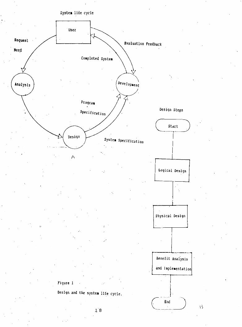
This Is the last phase of the whole process and the. model developed before can be c9ded bya suitable language. Which can afterwards used to reach the goal and a procedure manual canbe prepared to assist the user so that task assigned to him or her becomes easy. A welldefined program listing is also an essential part of the process. With the help of this future
modijication and maintenance of the system becomes less cumbersome.
Figure' - 1 represents a summary of the whole process in form of block diagram. "A" part ofthe figure indicates the position of the design process in respect of the system me cycle. In
the part "6" all the steps needed for design are shown.
17
syste. Ille cycle
Syste. Specification
Des Ign steps
Evaluation Feedbac~
Co.pleted Syste.
Progra•
Request
Nee~
.J
Logical Design
-Physical Design
-_...Benefit Analysis
and I'ple.entatl
I-
18
A
Figure 1
Design and the syste. life cycle.
CHAPTER 4
LOGICAL SYSTEM DESIGN
At this stage the environment is defined and requirements and objectives of the hospital isanalyzed.
4.1.1 Environment of the Hospital
The organization in this project is the hospital. The environment of the hospital is composed
of front desk, wards and administrative office. The front desk provide services to the patientswho seek admission to the hospital, their attendants, or the visitors to the hospital. Patients
seeking admission means who have been referred for admission into the hospital and requiredto stay there for a span of time. Patients' attendants mean patients' relatives or friends and in
general not hospitai staffs. Visitor may be any person who has certain reason to come to thehospital and/or certain queries that he/she wants answered.
Normally patients are referred for admission by the field practitioners or a patient's report to
the outdoor of the hospital and the physician attending them suggests admission into thehospital. In most of the cases the patient is accompanied by his relatives or friends as at.-
tendant. However, a patient may also come alone. Other than these patients and their asso-ciates' other visitors visit the hospital every day. They may be either official or non official.
Official visitors may come to assess the performance for hospitai facilities for deveiopmentpurpose. Non officials may have some other queries like the chamber of a particular doctor or
his telephone number, future admission possibilities or its formalities, ward information, etc.
The hospitai consists of several wards with a name and each ward has some beds. Each bedaccommodates. a single patient. At any point in time some beds may be occupied whiie some
others may not have any patient. Upon receipt of the relevant documents, the front deskoperator looks for bed position of the wards of the speciality in which the patient is referred.
If no bed are available,. the request is either denied or appropriate measure may be taken assettled by the enterprise rule. The hospital under study provides extra beds for such patients.However, this may not be the practice in other hospitals.
The bed once allotted may be canceled or changed to other ward upon the physician's adviceor discharge certificate. In the case the bed will be available to the next patient coming for
admission. The change of bed to other ward is similar to new admission to that ward.
Once the patient is admitted into a particular ward the activities related to his case starts. HisInvestigation, i.e. pathological tests may be recorded. These might have been done earlier, i.e.
prior to the admission into the hospital or current after the advice of the physician. Patientcondition writing however starts after the admission of the patient. The patient may have some
earlier important condition record important for his future management or treatment purposes.The advise from the physician begins from the start from the date of admission and continues
till the occupancy of the bed by the patient. On discharge the patient receives a report on
19
the pathological tests conducted and medicines administered during his stay. Some of themore useful or Interostlna nntn mny hn J>rRsRrvnrlfor rnsnnrr.h usn.
4.1.2 Requirement Analysis of the Hospital
The main requirement at the front desk Is to have a .quick picture of bed position In a particu-1ar ward.
Specifically, the doctor attending a particular patient is also interested in the patient's pathologi-cal findings and patient's observations to arrive at a proper diagnosis and treatment. Pathologi-
cal reports and Condition data of the patients are to be recorded and kept in the informationsystem In such a manner so that It can be effectively used by the physicians for diagnosticpurpose and prescribing medicine.
The nurses attending a patient requires to know about the doses of medicine prescrlbec by thedoctors and Its time of administration. Patient diet Is also an objective to know. The man-agement wants to keep the duty schedule of other personnel. A variety of mecicines may beadministered and the patient may have some early record of medicines already admlnisterec to
him or her. The doctor may also recommend the patient's food as well.
All the doctors have a duty schedule in wards and that. covers round the clock attendance.Some specialist doctors have some regular rounds and may attend serious patients upon
emergency calls. Nurses and some other staffs also work on the basis of a schecule.
The hospltai has a management body to control the activities of its employees. It also has anoutdoor section where the patients only receive medicine and go back to their houses. An
outpatient, however, can require admission Into the hospital If found seriously iii by the dutyphysician. The hospital authority assumes no responsibility for the patients' condition monitor - .
Ing or administration of meciclne. All these iriformatl,?n are requirec, and require to retrieve Itas and when necessary, for patient care and disease diagnostic purpose and the hospitalmanagement planning and decision making.
4.1.3 Requirements of MHIS
Considering these information that the hospital patient care and management require dally,manual operations would be teclous and cumbersome. The primary purpose of this information
system is, therefore, to ensure easy and fast retrieval of necessary filtered data basec on querycondition instead of searching into a huge bundle of physical recording documents i,e to save
time so that more time could be given to talk. to, listen to and serve the patient. Anotherpurpose of the system Is to assist management in smooth operation through better admInistra-tive control and thus maximize revenue.
4.1.4 System Requirements
The requirements of the hospital Information system are:
20
,,
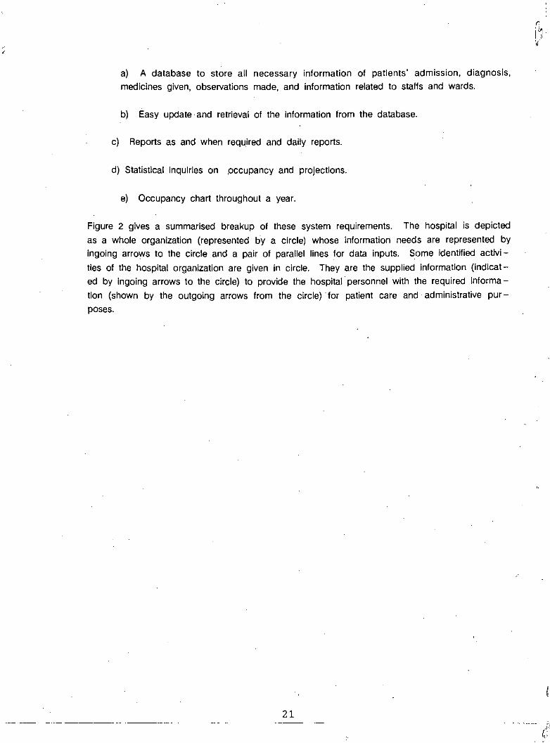
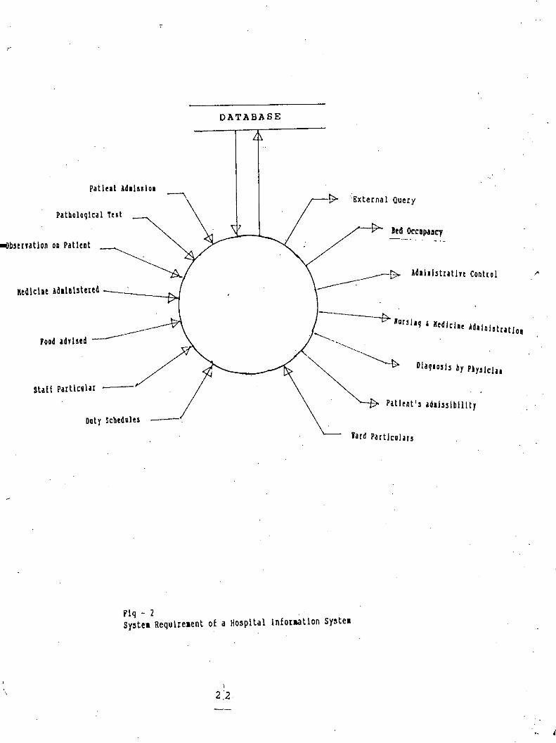
a) A database to store all necessary information of patients' admission, diagnosis,medicines given, observations made, and information related to staffs and wards.
b) Easy update. and retrieval of the information from the database.
c) Reports as and when required and dally reports.
d) Statistical inquiries on .occupancy and projections.
e) Occupancy chart throughout a year.
Figure 2 gives a summarised breakup of these system requirements. The hospital is depicted
as a whole organization (represented by a circle) whose information needs are represented byIngoing arrows to the circle and a pair of parallel lines for data inputs. Some identified activi-
ties of the hospital organization are given in circle. They are the supplied Information (indicat-ed by Ingolng arrows to the circle) ta pravide the haspital persannel with the required informa-tian (shawn by the autgaing arraws from the circle) for patient care and administrative pur-pases.
21--- .J:!"
(:
DATABASE
Patl,.t ld.1 •• 10.
Patl,nt'. adl!•• lblllty
I'
Dlaq'o,!, by PI !y. cla.
ld.l.l.tratlvt Cont[ol
led Occapucy--_...
'External Query
lard Part!co!ar.
----j;.. lor'h_ I, I,dlcl" Id.1 !. • .tratlo.
,
Daty Sch,dal,. --------.
Patholoqlcal T,.t
stall Particular
K,dlcl., 1dI1.I.ter,d
"'Ilb.uvatlon 0' Patl,.t
Flq - 2Sy.te& Requlrelent of a Ho.pltal lnforaatlon sy.tel
l
22
i
4.1.5 Functional Specification
The major functions of the Hospital Information System are:
a) Process of admission and discharge operation at front desk.
b) Process of diagnosis and Medicare at the ward.
c) Process of administrative control at management office or with In the hospitaloffice.
4.2 .System Analysis and Specification
This phase .collects the user requirements concerning those parts of the Hospital InformationSystem which are to be automated and formalize them into description of data, tasks, eventsand constraints.
4.2.1 Decomposition
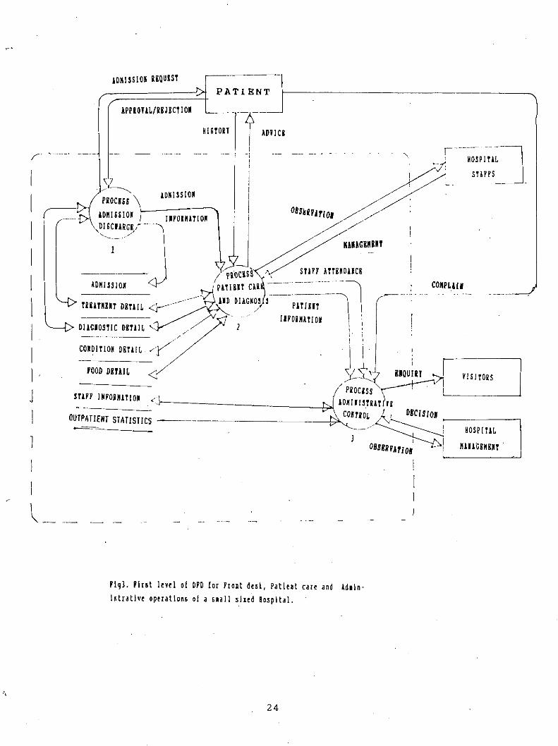
The first level .data_flow_dlagram(DFD) of Figure 3 displays the information flow among thethree tasks: Front desk operation.Ward operation and Management operations. The dashedlines delimit the functional subsystemwithin a selected area. Subsystems outside this area (I.e.outside the marked boundaries) are not the concern of this project and thus do not affect theanalysis.
4.2.2 Refinement
A single DFD Is not sufficient to depict the flow of data of the three tasks, thus. further subdi-visions are done to produce lower level DFDs. Each task is expanded into several subtasksas shown in Figures 4 to 6. The numbers in the lower portion of the bubbles indicate tasknumber.
The second level DFD of process Front Desk Operations consists of two sub- tasks Fig- 4 (1.1and 1.2) namely change admission and cancel reservation. Similarly patient care and medicineadministrationhave four sub- tasks Fig- 5 (2.1 to 2.4). There are patient condition registration.updating medicine. create medicine. create pathological test. The process Administrative controlhas three sub- tasks Fig- 6 (3.1 to 3.3) and these are: Change & Update Duty Schedule andUpdate Ward Data.
rlq-6 S"OId I,n lorD 01 pro",,-) Ad I• nlst,ati" Control.
27
4.2.3 Identification of Database Information
After the Information requirements have been documented by the DFDs, the next step !s tochoose what data elements are to be included In the database. Since the data store from the
DFDs represent a fine delayed data, they must be analyzed what elements are suitable fordatabase storage.
There are 7 data stores from the DFDs
a) Inpatientb) Ward
c) Medicine
d) Pathology
e) General Conditionl) Staff
g) Food
In addition to there is another data store is required for archive J1'lJrposeI,e. outpatient.
Two more dictionary data stores are proposed to facilitate coding of Pathological Samples andDisease Diagnosis.
4.3 Structural Analysis
At this point, the problem of representing all relevant aspects of the enterprise at a sufficient
degree of detail to capture the database requirements is analyzed. The conceptual schema Isdefined by first analyzing the static properties 'of data.
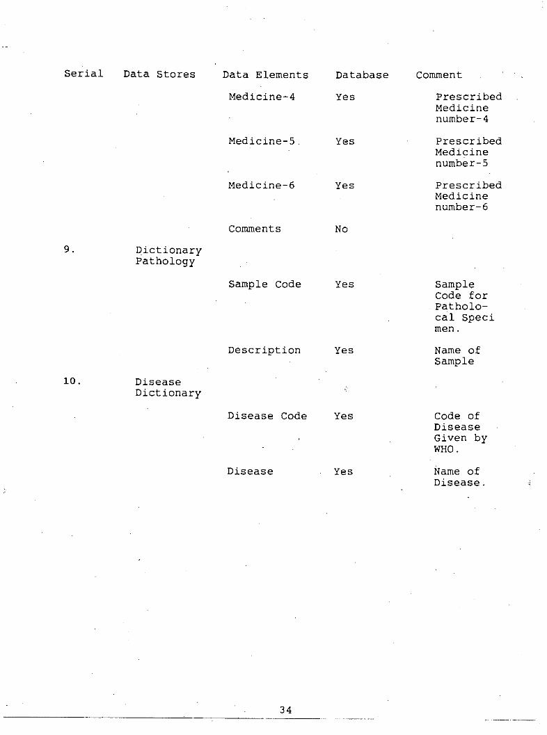
Structurally each data store comprise several data element or attribute for constructing thewhole store. Table - 1 gives a list of structures of the elements of data on the basis of datastores previously Identified.
In the medicine data store though the doses are not conventionally prescribed in form of struc-
ture shown. But this dose structure can easily derived from the prescription given by thedoctors and easily be coded to fit into the database.
The data store Pathology Dictionary is basically a dictionary on the names on variety 'of tests
advised for various pathological diagnostic purposes. This dictionary will make the PathologicalInformation data store efficient by enabling the user to code the type of Pathological test anddate entry also be easy and fast.
The data store Disease dictionary is for housing the codes of International Classification ofDiseases. The codes are assigned by the World Health Organisation and are widely accepted
to name a disease based on history, clinical findings and laboratory investigations. The dIc-t~onary will make the inpatient data store simple and easy retrievable. The Implementation of
these codes will also simplify the data entry as was the case with Pathology dictionary.
29 .
Table - 1
Analysis of Data Stores
Serial Data Stores Data Elements Database Comment
1 PatientParticular
Inpatient Number Yes generated bythe systemto avoiddata incon-sistancy
By analyzing the DFDs & data stores a list of entities and relationship is determined.
4.3.2 Drawing of EROs
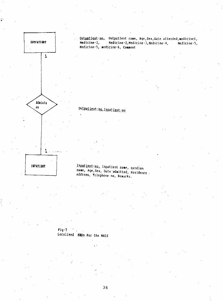
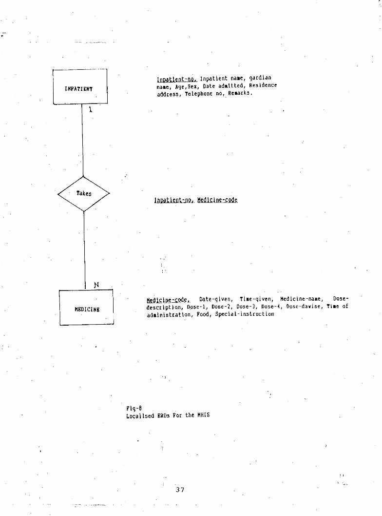
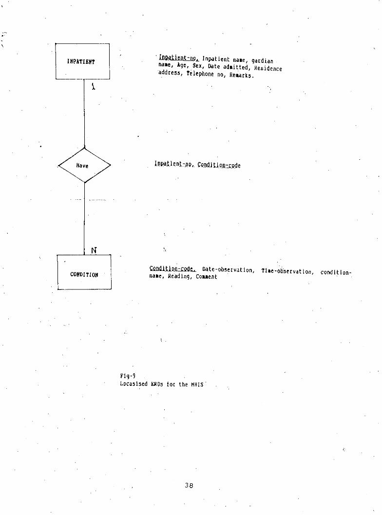
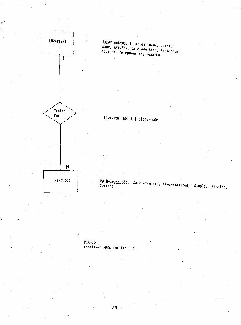
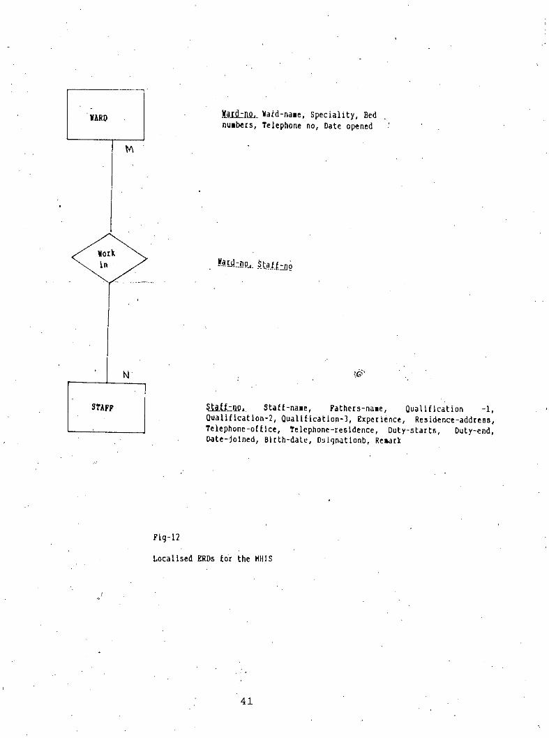
Figuros 7 to 12 silow lile localized EROs as a resull 01 lile Idellllficalloll 01 ellllly alld relalioll-ship types. A one - to - one (1:1) between outpatient - admits as - inpatient. Patient - have-
condition represent (1on) means one patient can have many condition. In many - to - many rela-t1onshlp(M:N) one staff can work In many warda and a ward may be workplace of manystaffs.
The localized EROs are grouped together to form the normalized ERDs. Figure - 13 Is such agrouped ERD obtained from the localised ERDs of figures 7 io 12.
4.3.3 Identification of Attributes
Attributes are the properties of. an Entity. These attributes when chosen by itself can serve as aprime indicator and establish relationship with Entities. Thus the attributes Can also Identify each
entity and relationship. The key or prime Indicators were shown in figures 7 to 12 in the formof underlined attributes.
4.4 Behavioral Analysis
In this last stage of logical system design. the behaviors of each entity and relationship Isdescribed according to their own lije histories. Which can be incorporated to develope a modelusing .the Entity - Relationship Diagram,
35----_ .._----~._-_...
OUTPUUlT
1
mUlm
.O.olllAti ~ot -.00. Outpa tie nt n•• o, Aqe, ~ex, da Ie -a ttonded •• ed Icine I ,""die 1no- 2, HedIe Ino -2, Hedlei rio- J, Hedl~ Ine - 4, HedIe Ine - ~,Hedlelne-5, .edlelne-6, Co•• ent
Jm~"UenknQ. Inpatient na.e, qardlanna.e, Age,Sex, Date .• doltted, Residence.address, Telephone no, He.arks.
Flg-7Localised BROs For the "HIS
36
INPATIENT
MEDICINE
iD]9tlent-02L Inpatient nale, gardlannaae, Aqe,Sex, Date adaltted, Residenceaddress, To lephone no,. Reaark •.
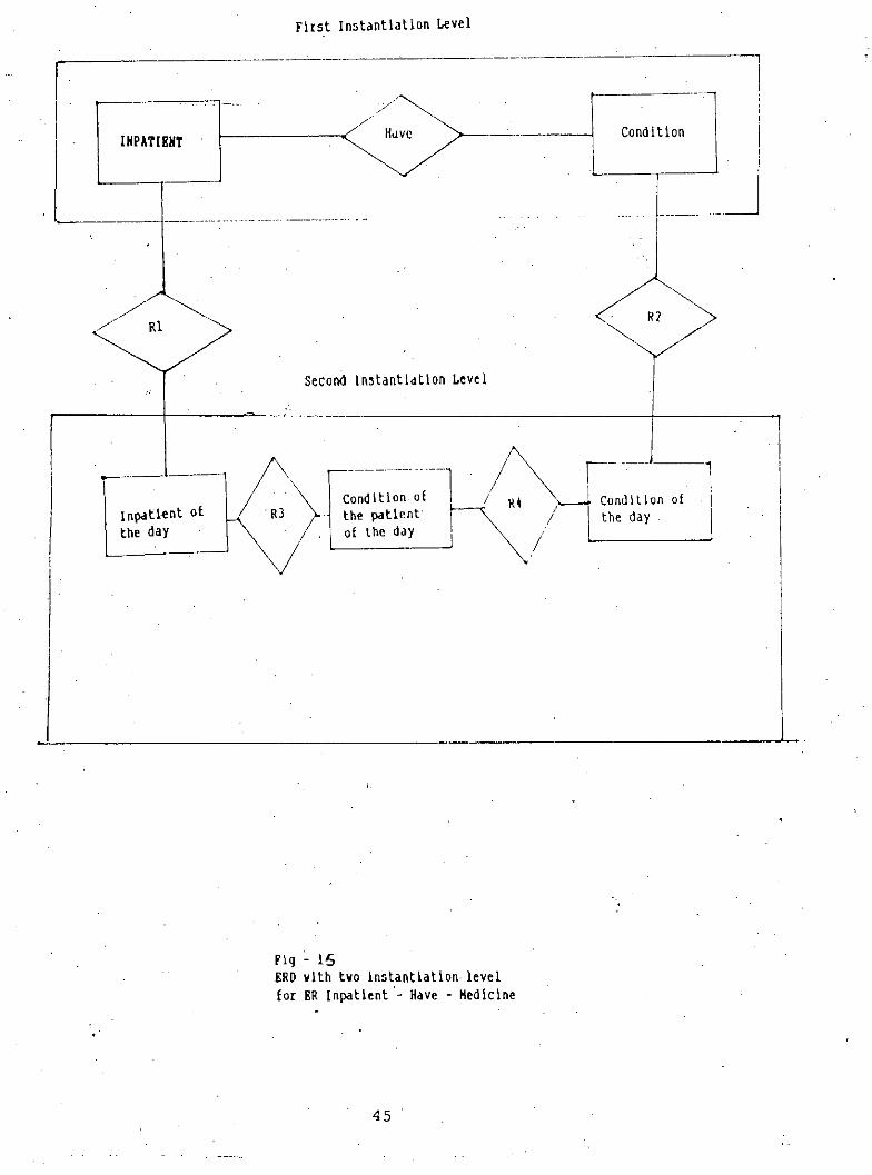
The, line span of day is, chosen fo~ instantiating the entities and relationship, Daiiy managementof activities within the hospital is critical in a hospital is critical so It is desirable to describethe day to day behavior of the data,
4.4,2 Identification of User .queries
User queries many differ with different Instantiation level. These Instantiation ievels were shown
In the diagrams of figures 14 & 15 but queries on the basis of this change of instantiationlevel were not considered in the Implementation phase of tha study,
The user queries' are' Identified as a result of the dilierent user forms at the Ilrst Instantiation
levol. A compArison of thoso ClllorioR wllh thOROnnrrnlorl In tho rnCllllrnmnnl Ror.llon RolIslloshonco fullliis tho nood.
4.4.3 Development of ERDBs
Once a localized ERD Is abstracted to Its second instantiation level. Petri net graphs may be'
developed for each entity and relationship Is an ERD, Result of this produces the ERBD (EntityRelationship Behavior Diagram),
Since the implementation phase was only restricted to the first Instantiation level this part of
work was not undertaken and may be a future course of work.
Analysis of the life History of Entities through their state is to be mode so that a nil stateInstance exists In order to keep the Integrity of the database. Behavior description is another
vital part of the ERBD's development process. In order to describe the behavior that exists foreach entity and relationship sets, the state and transaction descriptions are defined. The identi-
ficat~on of dynamic degrees to each entity and relationship provides an overview on how thedata evolve over a period of time and its specification may be considered at the last. Eventscause a change In the state of data elements described In, relation to a specific activity withinthe enterprise. Analysis of there properties of the data, thus, ensures completeness and integrity
of the database under the various application of the enterprise.
43
<\.-" ,
INPATIENT
First Instantiation Level
_n~0--_Hed::l~cl~~
,/, ,
/ -"-,.// Rl R2/
Second InstantIation Level
Inpatlent 01the day
., .
Fig - 11ERO vlth tvo instantiation levellor ER Inpatient - Take - HedIclne
44
First Instantiation Level
,..---------------------------------
Condition
Second In~tantiatlon Level
,,I
! ~J
Rl
.------
Inpatient ofthe day
----.--------.-.-1 /~ I J_-1Condition. of / RI '\.-.J Condition of . Ithe patient 0 I I the da. Iof the day . yI .
Fig - 15ERDv lth tvo i.nstantiati on. leve Ifor ER Inpatient '. Have - Medicine
45
L
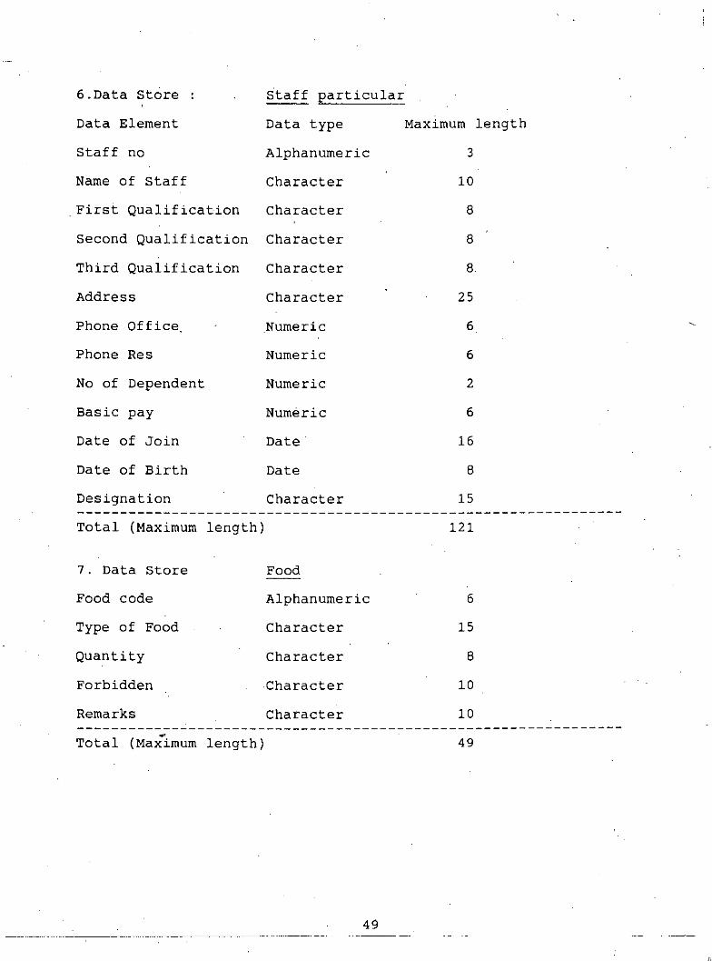
4.5 Space Allocation for Data Stores.
From the analysis presented above the data stores were identified. These datastores haveseveral attributes as detailed in the tabie - 1 in order to process the user queries. The attributesobtained may be kept in a database as per the allocated maximum length described in thetable - 2. The table also shows the type of data to be kept in that space.
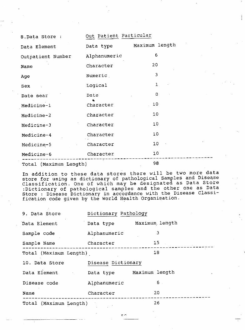
Medicine-6 Character 10---------------------------,------------------------------------Total (Maximum Length) 98
In addition to these data stores there will be two more datastore for using as dictionary of pathological Samples and Disea,seClassification. One of which may be designated as Data Store:Dictionary of pathological samples and the other one as DataStore : Disease Dictionary in accordance with the Disease Classi-fication code given by the world Health Organisation.
The MHIS system is designed specially for IBM microcomputers and ciones (IBM PC compati-b~es) that run under the MS- DOS (Microsoft - Disk Operating System), The system ideallyneeds a microbase Local Area Network (LAN) to connect the front desk operator. ward andadministrative office work station to the file server or the super station. However the superstation may alone work without a network. with the limitation of one terminal and may includethe following minimum peripherai devices.
a) CPU.with at least 640 KB RAM
b) 20 x 80 character monochrome display
c) Keyboard
d) Two disk drive (of which one must be hard disk)
e) 80 or 132 character printer
The confiouratlon may be expanded to increase the memory size or to use more hard- disks.As data increases in a given time period. It will necessitate the organization to increase alsothe main memory and storage devices.
In case of a network the workstation should have the following minimum configuration.
a) CPU with at least 256 KB RAM
b) 24 x 80 character display
c) Keyboard
d) One Fioppy Drive
Color monitors can also be used for both the cases with a color adapter In the CPU unit.
5.2 Language Implementation
Initially it was intended to use SOL as implementation language. Later dBase- IV was chosenfor several reasons.dBase is designed for application areas in data processing. It is well suitedto "data processing applications. since it contains such powerful built In functional elements "asdata entry features, table search function and sort facilities. These features of dBase are de"-
51
signed to aid the programmer in organizing, accessing, updating, reordering and reporting datain file, dBase also provides extensive facilities for file handling whose organizations are either
indexed or random. File manipulation functions and features found in data processing applica-t~on which is exactly in the nature of the MHIS system.
The dBase used for our purpose is the Ashton - Tate dBase version IV that runs under
MSDOS version 2.0 or greater, or Compaq DOS version 3.31. This version of dBase requires aharddisk of which 3.5 MB must be free. The minimum memory requirement Is 640 KB RAM.
a) dBase is validated at high level, meaning more standard dBase features, including
indexed files and dynamically called subrou!lnes and available for program use.
b) dBase program. with the help of clipper can be converted to executable pro-grams..
c) dBase support screen handling facilities and Interactive system.
5.3 Collection of Data
Data generated in each area of the system under consideration is related to the activitiesconcerned and has it's own shape and format. Therefore a throughout coding of data as perinformation system requirement at the field level may cause error. Hence data forms developed
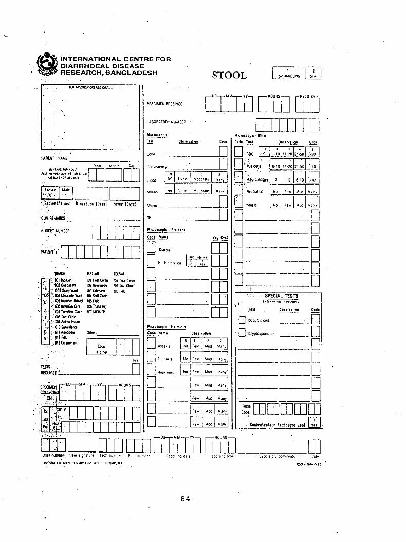
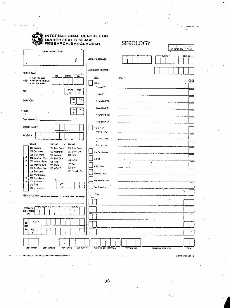
already developed in different areas is coded later and reshaped In accordance to the Inputformat requirement as described in section 5.4. Some of the developed data used by differentareas are attached as Appendix - A.
5.4 Input / Output Design
The three dialogue designs menus, question & answer and form filling are used in designingthe screen Layout. The menus enable the user to select the function to be performed by the
system, such as patient care activities in the ward, administrative queries, quit from the pro-gram, query processing in SOL and a log off totally from the dBase program. In the form fill-
ing, the system ask the user to fill- in data that are processing. A list of screen layouts havebeen attached.
The report formats are derived from the user requirements. These are formatted in such a way
that these satisfy the users specifications and how these will appear on paper and screen.Each report is distinguished from the other by an. appropriate title because some reports con-
tain the same Information but differ from how the user views them. Please refer to the MHISprocedure manual for the use of different report formats.
Figure - 16 welcomes the user and would ask for an input from 1 - 5 for Patient admission,
Inhouse patient care, Administrative control, Outpatient data entry and Database handling InSOL. Input no - 6 will be used for exit to DOS, the operating system.
52
c-
Figure - 17 would be resulted upon selection of no - 1 from figure - 16 and will ask the user toselect 1 to 4 for Ward Information, Bed occupancy, returning back to previous screen and. Exit
respectively.
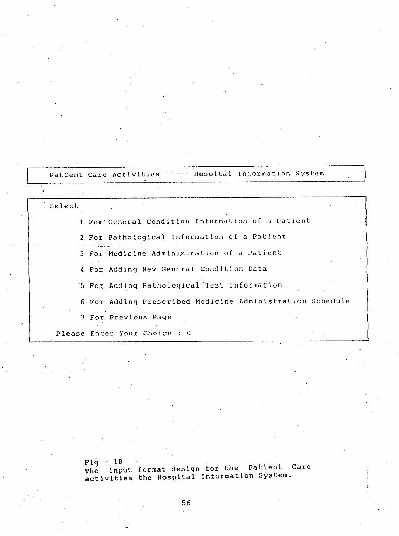
Figure - 1B is the result of selection of no - 2 from figure - 16. This input format has sevenoptions. 1 to 3 is for information regarding General condition, Pathological and Medicine Admin-
istrat~on respectively. 4 to 6 Is for new data entry for General condition, Pathological andMedicine administration. No-7 is lor returning to previous page i,e to figure-16.
Figure 19 is the selection no - 3 from the figure 16 and allows the user to process query on
particular employee's duty by nO.1, or ward duties by nO.2, as Bed Occupancy by nO.3 & forchanging an Duty Schedule by No.4, or Ward data by NO.5, on personal data for previous
page nO.7
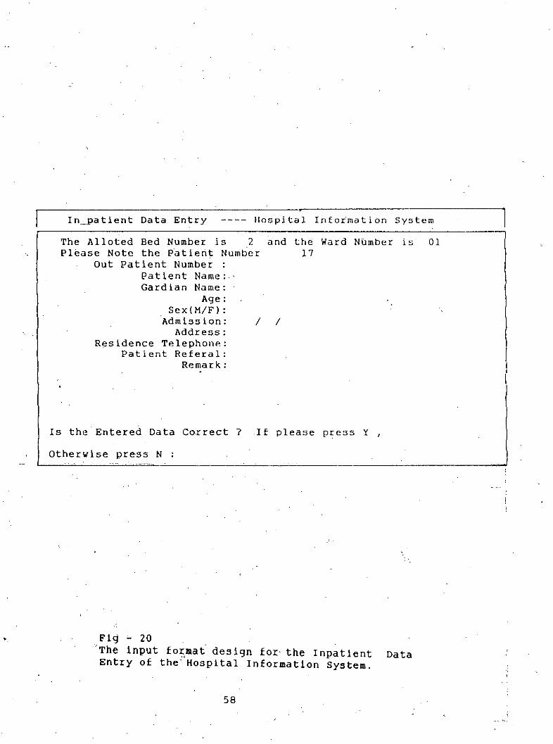
Figure - 20 is the input format for Impatient data entry and the. menu will be entered throughthe selection of nO.2 of figure - 17, which will first report about the bed position of a particular
ward and will take the user to this format upon selection of a vacant bed.
Figure - 20 will result from the selection of no.4 from figure 1B and allows the user to enterdata on different fields related to condition.
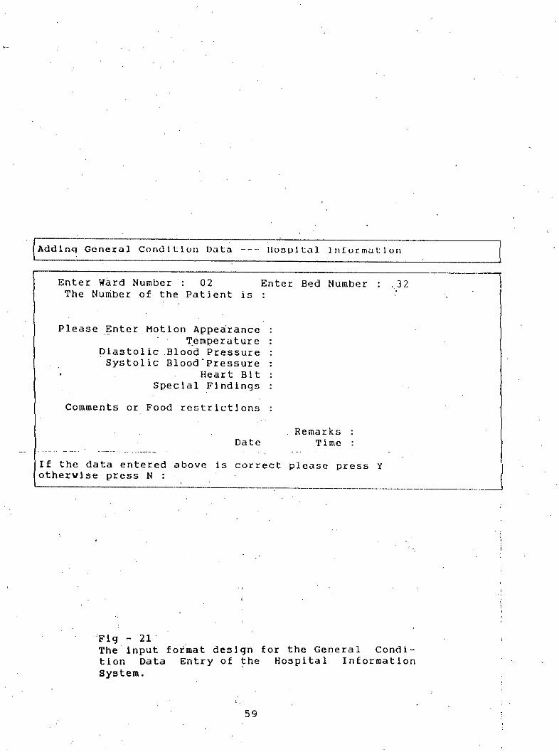
If no - 5 of figure 1B Is selected Figure -' 21 will be the result and the format will allow the user
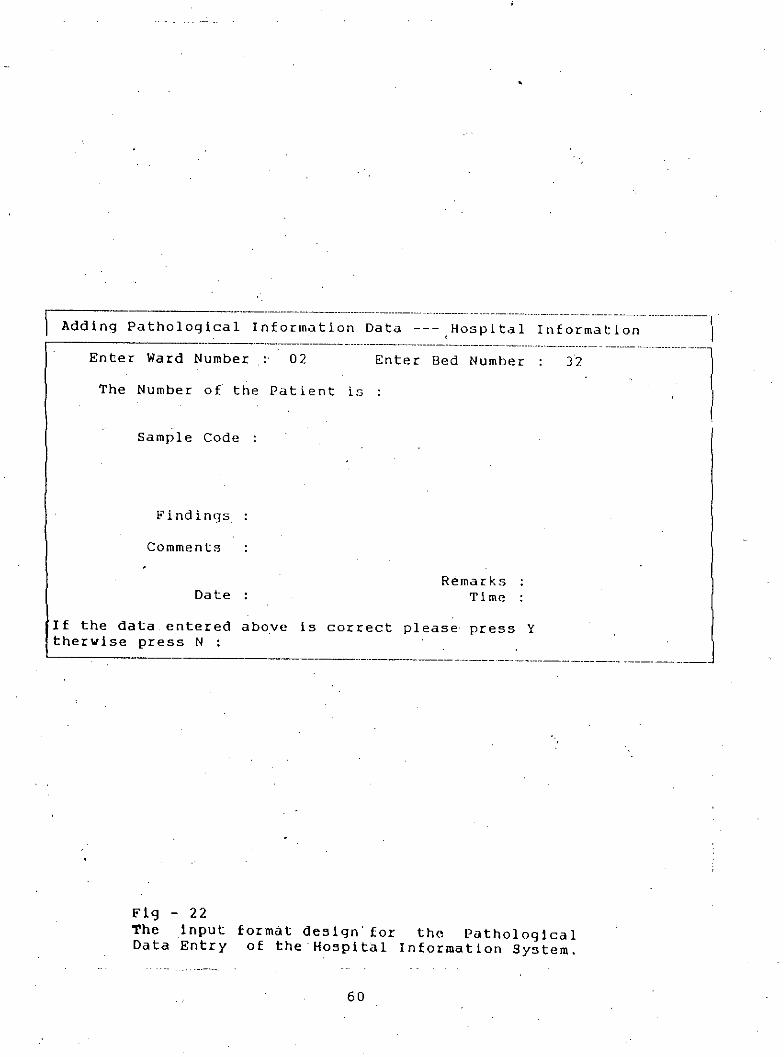
to input data on several parameters on pathology.
Figure - 23 Is for Medicine Administration data entry & is a resuit of no - 6 seiectlon from fig-
ure-1B.
Outpatient Data Entry form is presented in figure - 24 and is a result of selection of no - 4
from figure - 16.
53------_.-. -------_ .._-----------
WELCOME TOIIOSPITAL INFORMATION SYSTEM
--'-~-----'-------_.._._------------,Select
2 For Inhouse Patient Care
3 For Administrative Control4 For Out ., Patient Data Entry
5 For Database Handllnq in SQL
6 For Exit to DOS
Please Enter Your Choice 0
Fig - 16The input format design for the openning Menuof the Hospital Information System.
54
HOSPITAL INFORMATION
Select:
PATIENT ADMISSION--_.~----_.,,----------_.-
1 For Ward Informution
2 For Bed Occupuncy in u Purticular Ward
3 For PreviouD screen
4 For Exit
Please Enter Your Chioce 0
Fig - 17The input format design for the Patient Admis-sion of the Hospital InformatIon System.
55
I l_'al t e_'_n,_lc__a_r_e_A_C_l_'_i_v':'=~~_=_-:,::"::"::,_H_O_S_P_i_l_'a_._1_1_n_I_:_o_r_m_"._t,'__I0_, _n_s_y_s_t:_e_m ~
Select
1 For' General Condition Information of il Patient
2 For Pathological Information of a Patlent
3 For Medicine Ad min Ls t rat ion of a Patient
4 For Adding Ne'J General Condition Data
5 For Adding Pathological 'Test Information
6 For Adding Prescribed Medicine Administration Schedule
7 For Previous Page
Please Enter Your Choice 0
Fig - 18The input format design for the Patient Careactivities the Hospital Information system.
56
Administrative Control ----- Hospital Infor~ation System
Select
1 For Query on Individual's Duty2 For Query on Ward Duties3 For.Query on Bed Occupancy of a Ward4 For Changing Duty Schedule5 For Changes in Ward Data6 For Changing/Adding .Personnel Data7 For Previous Page
Please Enter Your Choice o-------._----------------_._ .._-------------- .._------------
Fig - 19The input format design for the AdministrativeControl of the Hospital Information System.
In_patient Data Entry lIospital tnfotmation SystemThe Alloted Bed Number is 2Please Note the Patient Number
Out Patient Number :Patient Name:,Gardian Name:
Age:Sex(M/F) :
'Admission: /Addres,s:
Residence Telephone:Patient Referal:
Remark:
and the Ward NUmber is17
/
01
•
Is the Entered Data Correct? If please press Y •
Otherwise press N :
Fig '- 20'The input for,mat'degign for' the Inpatient Data
Enter Ward Number 02 Enter Bed Number .32The Number of the Patient is
Please ~nter Motion Appearance~emperature
Diastolic Blood PressureSystolic Blood-Pressure
Heart BitSpecial Findings
Comments or Food restrIctions
DateRemarks
TimeIf the data entered aboveothervise press N :
is correct please press Y J---'-----_._----.--------_._-_.~--_._-----_._-,---_._-._--------
,;i
Fig - 21'The input fot~at design for the General Condi-tion Data Entry of the Hospital Informationsystem.
59
----~----------------------------------------- --------- ---------------- ------------------ -- -- -- ------ ------- ---------------1Adding Pathological Information Data ---,Hospital Information I
------------------------------------------------------------------------------- ----- --- -------------1Enter Ward Number: 02 Enter Bed Number: 32
The Number of the Patient Is ISample Code
F'indings
Comments
DateRemarks
Time
If the data entered above Is correct please press Ytherwlse press N :
format design- for tho pathologicalof the Hospital Information System.
60
Adding Medicine Admini"tcation :Jchedule --- 1I03pit..t1 inlorm"tionEnter Ward Number: 02 Enter Bed Number : 32
Medicine NameDescription of Dose
Fir,;t DoseSecond DoseThird DoseFourth Dose
Time Interval Daywise DoseTime When to be AdministeredSpecial Instruction if any
RemarksDate
If the data.entered above is correct please press Ytherwise.press N :
Time
---._----------------_._-._-----------
Fig - 23The inp~L format de~lgn for thevised Data Entry of the HospitalSystem.
61
Medicine Ad-Information
----------~-------------_._--------------_. __ ._-,Outpatient Data Entry -------Hospital Information system
n~.
Enter the data given belov
Outpatient NumberNameAgeDate
Hedicine OneHedicine Tvo
Medicine ThreeHedicine FuurHedicine FiveMedicine Six
~: ---------------------------------------1
,- \
Fig - 24The inputData Entry
format desiqn for the Out-patientof the Hospital Information System.
62
.-
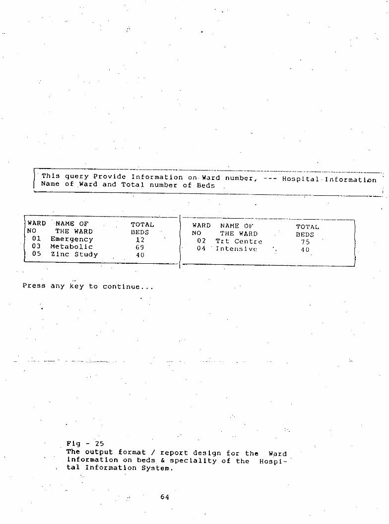
Figure - 25 Is a pure reporting format on ward Information and will be generated through selec-
tion of no - 1 from figure - 17.
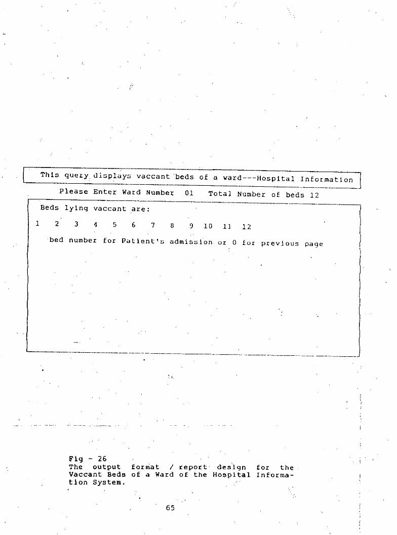
Figure - 26 is in a mixed format this will report about the vacant beds of a particular ward andwill also allow the user to select bed no for particular patient. This will be entered through the
selection of no - 2 of figure - 17.
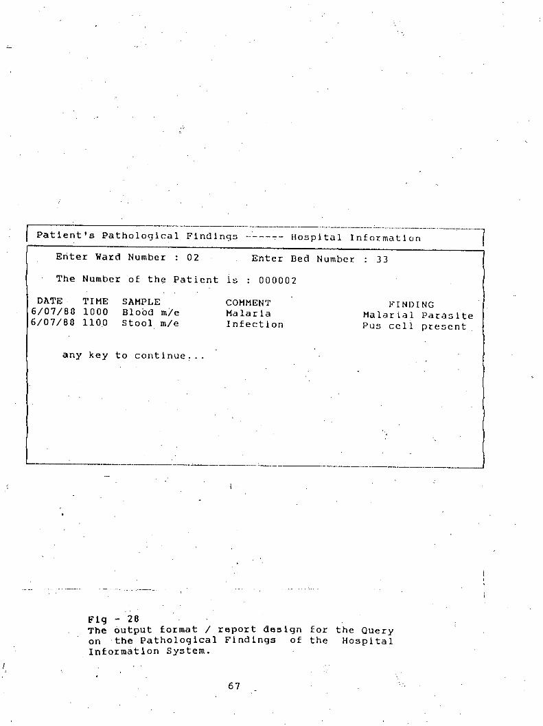
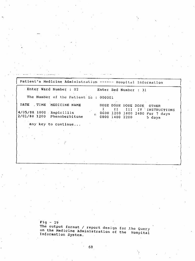
Figures - 27, 28 and 29 are purely report formats and be accessed through the selection ofnos - 1, 2 & 3 of figure - 18. The figure - 27 presents several condition of particular patients
Identified by bed no and ward nos. On the basis of similar Identification the figures - 28 & 29reports pathological & medicine Information respective.
Fig - 28The output format I report designon the Pathological Findings ofInformation System.
67
for the Querythe Hospital
Patient'a Medicine Administration 1I0Bpital InformdLlonEnter Ward Number : 02 Enter Bed Number : 31The Number of Lhe Patient is 000001
DATE TIME MEDICINE NAME DOSE DOSE DOSE DOSE OTIIERI II II I IV INSTRUCTIONS4/05/88 1000 Ampicillin
"0600 1200 1800 2400 For 7 days2/01/88 1200 Phenoberbitone 0800 1400 2200 5 days
any key to continue ...
III
-------------------------- .-J
Fig - 29The output f~rmat / report deaign for ~he Queryon the Medicine Administration of the HospitalInformation System.
68
5.5 File Design
The MHIS is basically a file management system. The entities and relationships and translatedin dBasefiles in such a way that one entity or relationship corresponds to one file and theattributes of the entity or relationshipcorresponds to one file and the attributes of the entity orrelationshipare the field in the file. Key fields are used during query processing.
69
CHAPTER 6
BENEFIT ANALYSIS
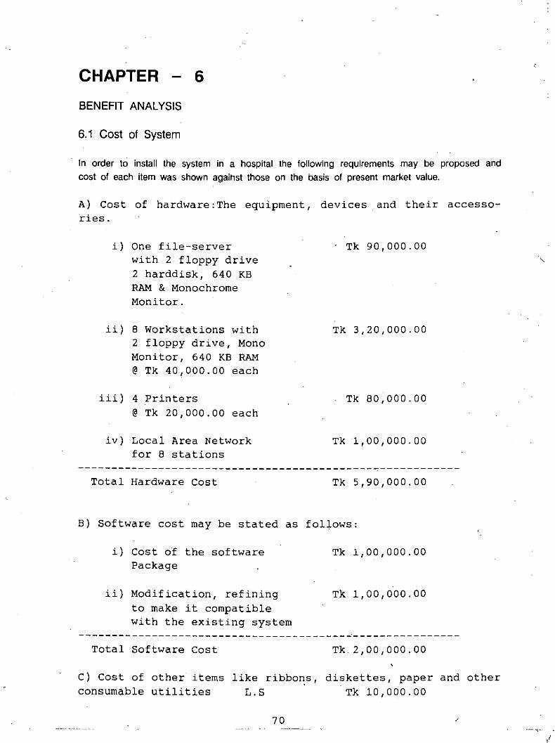
6.1 Cost of System
In order to install the system in a hospital the following requirements may be proposed andcost of each item was shown agaihst those on the basis of present market value.
A) Cost of hardware: The equipment, devices. and their accesso-ries.
C) Cost of other items like ribbo~s, diskettes, paper and otherconsumable utilities L.S Tk 10,000.00
70 /
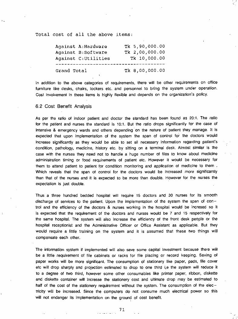
Total cost of all the above items:
Against A:HardwareAgainst B:SoftwareAgainst C:utilities
Grand Total
Tk 5,90,000.00Tk 2,00,000.00
Tk 10,000.00
Tk 8,00,000.00
In addition to the above categories of requirements, there will be other requirements on officefurniture like desks, chairs, lockers etc. and personnel to bring the system under operation.Cost InvolvementIn these items is highly flexible and depends on the organization's policy.
6.2 Cost Benefit Analysis
As per the ratio of indoor patient and doctor the standard has been found as 20:1. The ratiofor the patient and nurses the standard Is 10:1. But the ratio drops significantly for the case ofintensive& emergencywards and others depending.on the nature of patient they manage. It Isexpected that upon implementation of the system the span of control for the doctors wouldIncrease significantly as they would be able to set all necessary information regarding patient'scondition, pathology, medicine, history etc. by sitting on a terminal desk. Almost similar Is thecase with the nurses they need not to handle a huge number of files to know about medicineadministration timing or food requirements of patient etc. However It would be necessary forthem to attend patient to patient for condition monitoring and application of medicine to them .Which reveals that the span of control for the doctors would be Increased more significantlythan that of the nurses and it is expected to be more than double. However for the nurses theexpectation is just double.
Thus a three hundred bedded hospitai will require 15 doctors and 30 nurses for Its smoothdischarge of services to the patient. Upon the implementationof the system the span of con-tro~and the efficiency of the doctors & nurses working In the hospital would be incresed so itIs expected that the requirementof the doctors and nurses would be 7 and 15 respectivelyforthe same hospital. The system will also increase the efficiency of the front desk people or thehospital receptionist and the Administrative Officer or Office Assistant as applicable. But theywould require a lillie training on the system and it is assumed that these two things willcompensateeach other.
The information system If implementedwill also save some capital Investmentbecause there willbe a lillie requirement of file cabinets or racks for file placing or record keeping. Saving ofpaper works will be more significant.The consumption of stationery like paper, pads, file coveretc will drop sharply and projection estimated to drop to one third i,e the system will reduce itto a degree of two third, however some other consumables like printer paper, ribbon, disketteand diskette container will Increase the stationery cost and ultimate drop may be estimated tohalf of the cost of the stationery requirementwithout the system. The consumption of the elec-tricity will be Increased. Since the computers do not consume much electrical power so thiswill not endanger its implementationon the ground of cost benefit.
71
Tllo 11I11J101I101I1ll1l01i01 1110Iliformolioll ijYijUlIIl will lJollolll 1110otllor oroo 01 1110lIuijlJlwl Oij woll,like supply of uniform, overall report preparal/on on hospital, personnel inlormal/on ele. ButAnvillO<Ii,p 10 IhPRPwill nol h" mild, ill nompnrlRoll to lilA IMlorn nlnlpd nhovA nlld mny be1l01lloctod.
The cost Involvement of the othel areas of the hospital, not mentioned above have beenassumed to be static and not considered In the cost figures stated below :
The hospital Is assumed to have six wards, a management office and a front desk totalingeight location,
i)One super station orFile server with 2 HD& 2 FDD
ii) 8 work station with2 FDD @ Tk 40,000.00
iii) One Local AreaNetwork
,IV) Four Printers@ TK 20,000.00
V) Software
Sub-total
73. --- --------- -
Tk2,000.00
'l'K42,50,000.00
TK 42,60,000.00
TK 32,000.00
TK 32,000.00
TK 90,000.00
TK 3,20,000.00
TK 1,00,000.00
Tk 80,000.00
Tk 1,00,000.00
Tk 6,90,000.00
Assuming 10% Straightline depreciation or Category Ai.e Zero book value after ten yearsthe fixed complement because
Assuming 16.66 Straight linedepreciation or Category Bi.e Zero book rating after six yearthe fixed cost component because
TK 3,200.00
TK 98,2911.00-------------------------------------------------------Total fixed Cost for 1 year
b) Variablo Cost
i) Salary for 7 doctors@TK 12000.00 per month
ii) Salary for 15 nurses@TK 5000 per month
iii) Salary for 1 systemCoordinator / supervisor@TK 15000 per month
iv) Salary for 1 Asstt.System Coordinator@TK 10000 per month
v) Salary for 4 Data
vi) Cost of Stationery@TK 1500.00 (L.S) per locationper month
vii)Power Consumption7 location with 200 wattswith average use of 8 hours(11200 watts per day) 1 locationwith 300 watts with 12 hours averageuse (2700 watts per day) for 1 monthwith 417 KWH @ Tk 1.30 per KWH
Total for 1 mo~th
74
TK 1,01,494.00
TK 84,000.00
TK 75,000.00
TK 15,000.00
TK 10,000.00
TK 4,000.00
:TK 12,000.00
Tk 542.00
TK 2,00,542.00
I) For One year
II) cost of Maintenanceon category A of Capital
III) Cost of Maintenance onCategory B of capital'investment & Softwaremaintenance @12%
The above analysis indicates the cost Component of the area involved in the Operation of thehospital without the system reflects a figure of TK 42,60,000.00where as if the informationsystem is implemented it is expected to come down to a figure of TK 25,51,439.00whichmean that a saving of TK 16,68,000.00may be expected. Thus it may be opined that thesystem Is financially viable and may be confidently recommended for the purpose it is pre-pared.
6.3 General consideration
In with the implementation of the information system the hospital will enter into the era ofcomputerization.The system will ensure prompt and efficient managementof the hospital. Thepatients will receive their due care and treatment. Information and query processing on anyavailabletopic wiil be almost without deiay. The systemwill also render support for Incorporat-ing all other activities of hospital with the system as a part of future development.Above all itcan be said the systemwill improve the.quality of service and efficiency as a whole.
75
CHAPTER 7
IMPLEMENTATION
7.1 Program Coding
Tho Information systom was Intended to Implement In SOLIDS (Structured OuoryLanguage/Data System) but a suliable micro based system (e.g. Oracle) was not available andInteractive program package development was not possible so the decision of switching todBase- IV for program writing was taken with due consent from the advisor. In the programdevelopment Instantiation of the database and Its dynamic behavior of EER model was notconsidered and the program was restricted to a static model behavior. However the addedfeatures of the dBase- IV's to support SOL was used. As such all the files were created inSOL mode thus under a SOL database. With the additive features of the dBase these files canbe effectively handled by the dBase program Itself but cannot be restructured as dBa~e file.Since the files are under a database of SOL named DBHOSP. The CONFIG.DB of theDbASE- IV was accordingly configured through this DBHOSP path so that it gets all the files inthe search route. Updating or adding (BROWSE) new data to the files are also possible with adBase environment. But this may produce data Inconsistency and the user was warned accord-1ng~yIn the procedure manual.
For modification of file/table structures, adding and creating new file/table SOL environment isto be used. In case of restructuring previous table's different fields may be copied to newtable's fields. Or the newly created Table may be started afresh. Old and unused tables maybe dropped later.
7.1.1 Consideration
The main .consideration of the program development was the Interactive nature of the system.Though the system supports almost all day to day queries but accommodation of all ~osslblequeries in Interactive nature was not possible. However other queries can easily be handled bySOL because the tables were created in SOL environment under a database name of DBHOSP.In order to do that an user is to know the SOL in dBase- IV syntax which differs a little fromthe SOLIDS operable In IBM S - 370 mainframes.
7.1.2 Program Description
The program Is comprised of several modules. Each module starts as procedure subsequentlywith a specific module name and ends as return as suggested by dBase programming re-quirement. The first procedure pre- initializes the system to become compatible for the subse-quent task of the program. Each program module is sequentially named under a parent nameqry. Again these modules were sub - moduled keeping the parenthood name of the previousmodule with an appended additional digit for Its own Identity. These modules as well starts asprocedure and ends as return. Each module Is demarked by a double line in the program list-
76
Ing. The program listing also have comments line along with the program lines for Identificationpurpose of the module.
7.2 Procedure Manual
Tho program 10doolgnod to oupport Ihroo main oporallono of Hoopllal'o acllvilioo. Thooo oro (a)Frunl lloijk ijolvlcoij (Il) WOld Ilcllvillos (c) Admlnlslrttllvo Control.
Front dosk oporatlon 19moant lor pallont admloolon and dlochargo. Ward actlvilioo rofor topallen! care. Pallent's condilion monitoring, Palhologlcal report handling and admlnlstrallon ofdrugs are covered In this operation. Administrativeactivities involve overall management.of thehospital In question. It helps In maintaining duty schedule as assigned to different staff mem-bers' bed capacities In different wards and assigning duty places to different staff members.
The opening menu.allows the user to perform anyone of the above three options by choosing1 to 3 or the user can quit from the program and either process queries in SOL it he or shehas an exposure to SOL in dBase or can quit to DOS by selecting 5 or 6 respectively. TheNo- 4 selection of the option menu is used for entering data of the outpatients for archivepurpose and usable for query processing with SOL.
7.2.1 Front Desk Operation
The user Is to select No- 1 from the opening menu to enter into this part of the program.This part of program allows the user to admit, discharge or reallot the bed In the hospital.Select no- 1 and the program will show you the ward information which includes Number ofward, Name of ward and the total number of beds In that particular ward.
7.2.1.1 Admission
Check the eligibility of the pallent for admission of the patient. On fulfillment of the criteria ofadmission by the patient select No- 1 of the opening menu. Which will displays the listing ofthe wards, ward no and the bed capacity. From this screen enter the selected ward no. Onthe basis of the ward no entered the screen will. show the vacant beds of the ward and foradmission enter the bed no of a vacant bed and the system will ask for the data of the newlyadmitted patient and enter it carefully and the system will enquire about the data entered inscreen Is correct or not it correct press Y and the system will store it In the database.
If there is no bed left vacant enter a the system will go back to ward information menu andanother ward no may be selected to continue the admission procedure. If no bed are availablein the subsequentlyselected ward no option do the same as before and select another ward itsuitable and after doing all these exersize If a bed is still not available do the needful as defineby the hospital's regulation.
77
7.2.1.2 Discharge
For discharging a patient select No- 2 from the front desk operation menu and the system willask the user to enter the word No. and bed No. of the patient. " entered the system willdelete the patient particular from the database and report on medicine taken by the patientpathological test performedwould be produced.
7.2.1.3 Change of bed
Select No- 3 for change of bed occupied by a particular patient. The system will ask for thepatient's ward no. and bed no. After answering to this requirement the system will show award listing and upon selection of the ward no. the system will display the vacant bed. Onentering a vacant bed no the task would be over. If there is no vacant bed responded, followthe procedure'as detailed in admission.
7.2.2 Ward Activities
Selection of No- 2. from the main menu pulls user to this operation. This menu allows the userto enquire about patient care activities condition, medicine administration and pathologicalfinding by selecting 1,2 and 3 respective by.
7.2.2.1 Patient General Condition
Select No- 1 from the Ward Activities menu (obtained by selecting 1 from the main menu). Itwill ask for the ward No. and bed No. and enter those accordingly and the system will displaythe general condition data of that particular patient.
7.2.2.2 Patient Medicine
Select No- 2 from the ward activities. The system then.will ask for the bed no. and ward no.and on receipt of these requirement the system will display the list of medicine Administeredwith dose and time.
7.2.2.3 Patient Pathology
Select No- 3 from ward activities and as before the system will ask for ward no. and bed no." you enter those the system will display the pathological information of the patient.
7.2.2.4 Data Entry for General Condition
Select No- 4 from the ward activities. Enter bed no. and ward no. and the system will ask forgeneral condition data. On completion of the data entry the system will ask whether the userwants to add data to database or not. If Y Is pressed the system will take the user to theward activities.
78
j,
7.2.2.5 Data Entry for MediciAe \
Select No- 5 from the ward activities and on receipt of ward No. and bed no. Several entryparameterswill be prompted and data may be entered against those. The system will ask theuser whether the data entered Is correct or not. If he agrees and press Y the system will putthe entered data to its database.
7.2.2.6 Data Entry for Pathology
Select No- 6 from ward activity for pathological data Entry. The system will ask for bed no.and ward no. as usual. On entering these the system will ask the user to check for correctentry of data and ask the user to press Y If found O.K. Then the system will add these datato database.
7.2.2.7 Returning back to Opening and Exit
Select No- 7 to do this. The system will take you to openning menu from wherelt is possibleto exit from the running program.
7.3 Program Listing
Program listing has a great role to play during maintenance of the system in due course oftime or whenever required. Without the listing of program codes the future development of thesystem Is extremely difficult.
The list of the program is given in Appendix - B.
79
'f
CHAPTER 8
CONCLUSIONS
8.1 Discussion and Conclusions
A practical step- by - step methodology for the design of an Information system using theextended entity relationship model is shown. Extensions of the entity - relationship to modelbehavioral properties of data are discussed In section 2.2.
All these methods used the interaction- oriented approach wherein the interaction betweenthe application and the environment is described as well as the causes of changes in theapplication. Although these methods used the same concepts of operations, events and eventsynchronizationmethod Is suitably adapted because It can be Integratedwith the E- R concep-tua~model. The model developed for the hospital information system In a way that the analy-sis of the net reveals Important Information about the structural and dynamic behavior of the
hospital Information system.
The process of behavior modeling leads to the development of user queries and dataformats which are used to assist the doctors and managers In hospital management.
The design process is also of interest since it offers a guide to the design of the data-bases and their modifications are Induced from external events. It introduces in a simple waythe notion of event that is commonly used In the literature but seldom clearly defined. Analysisof the event ensures the completeness and integrity of the database under various applications,of the enterprise. The methodology has been illustrated with a simple database design
problem,showing each design step In detail.
As a result, the facts of the real world which are of Interest to the enterprise are consid-ered from both static and dynamic points of view. The perception of data of the user Is re-fleeted In a natural way in the design of the MHIS architecture and also in the design tif the
programs.
The implementationplan is carefully considered so that the system can be run and modifiedIn any microcomputer machine. Thus, the language needs to be highly, portable and easily
modified and maintained by other programmers.
The system is highly interactive in nature so that the design of input and output shouldgive ease of use to the operator.
8.2 Recommendations for Future Works
The MHIS system Is strongly oriented towards simple Inquiry and this Is also a limit to Itsusofulnoss.Bocauso of tho Incompleto knowledgo of all tho facts to be stored, tho oroanlza-lion of lilo,o focI, In lho dulabaooaccording to lho ER modal mauna that lhoy can bo addodlaler on according to a predeterminedpriority, If required. This is an advantage over traditionalapproaches.
Additional functions ca~ be added, i.e. accounting, housekeeping, personnel & medicinestores as the present MHIS has Included only limited operations of the hospital. The MHISsystem satisfies only a small portion of the complete hospital organization thus, It Is desirableto add other operations so that the users can benefit more from this Information system.
The overall performanceof the MHIS can be evaluated In the future in order to determinethe efficiency of the system In terms of storage and memory allocations and response time ofeach transaction. A review and evaluation can help the person In charge of maintenance toImprove the MHIS system.
An element of lime, e.g. hours or minutes, can be incorporated Into the system when'observationsare made to accommodate many function in one day. A day as the smallest unitof time can hinder the doctor's decision amidst a long history of the patient which may haveseveralvariation and currently may not be In use.
/,
APPENDIX - A
DATA COillCTION FORMS
Courtesy: Laboratory Archive Unit, ICDDR,SThanks to Mr. Emsrat Hossain.
82--,---------_._--~ ,- -------
ICDDR.BDiarrh~eal Disease Treatment Centre Patient Record
Centro: Dhaka FIt.Study;Number ".•
Matlab"I 2 I Tekoaf 131Il
I I4
.• ,Adm. wt. t kyo ) 11111 W-IIILn--34 00 363B
I I I:N4o
Patient,Na.
DateName ...Fathers/Spouse's NameAiJo ... •••
Residence/Villll{l/.:lP: S.
.Di.5Ian~e ( KIlometer)
TifTl6
. .. Census No.
Oist/Upazila
M .F
'-I"l
I I I I I I I"5-.-----11)
" I I I I7"';2~-'--'-.'''7 1ij
I I I I II I... 22 30
t:,.L111
I I I21
I I I47I I56
~'.,:i41
I I~~I I62t:,.LI5 I
Favor
n:.joIYesl(j-,-
!._W8Itl..:Y J3
limoAbd. pain
jl'Jo!ycs-1o 1
Vomiting
"iNOTYOSIo 1
Bloody
INOTY"OSIu 1.
Onset,Mucoid
J.N°IYeslo 1
Other
---~----------------_._---------_._--------DistihoEu.: I NO.1 -L-O-O'-.-o
Outcome 1 Discharge 1 Admlttod I Rcld to other H~ Died I Sr. Dead .1, z o. 4 5Disch. Dale Time Sign
OOIWdf8tion. J NUll" I Mild! Mods!;jlli I Severo Iu i 2 3
Pulso : I Normal I Wet:k I FeoblB ! purse-j"e-st- io 1 l 3
.R(:~-pjrallon : I NOImal I RapId I Gasp \ Absent io 1 2 3
Abd. Disl : I No I Yos 1Nutrition: 1Normal I Thin I M-~Io I . .0 i 2
. eNS: ~~rmal I ConvulSion 1UnconscIOus I aotlljo 1 2-:r--Others
. Clinical Dlognosls
Stool. M/ENo I Yes Io I
OrelI No I Ve. I-0-,---
,IV.
I N0'1 Ye&o ,Madic~ne
RIS
i No IoYos I1
TC.Noo
Signature ..
DC. HCI/.I Yea
. 1
.. 'i58i:. 159
t.", .'J60
~f l",LI62r,. ..IB3
~~
t:,.,j ~*~f66
L, L168
",£16g
I~ LI70I i I,t llJ I,7T 77 79
ADVICE & PRE5CRIPfiON'Patient No.Dote of Adml~sion:Patiant'. Name
Rx. ••• i'
(ICDaR.B 1Pationt No.
Patient's Ni1mt'n,
PRESCRIPTION (ICDDR.8)
Slgnatur~Date of dlscha,'ge
Slgnllture0811;1
.'<.
83
Im,;- INTERNATIONAL CENTRE FOR~ .DIARRHOEAL DISEASE
RESEARCH, BANGLADESH STOOLfOlIlIMSTlG./.fOllS lISE CWt.Y.. ~ .
do pre* this part of the progarm is for openning menu of the programset status offclear@ 1,0 to 4,64 double@ 5,0 to 22,64 double@ 2,22 say "WELCOME TO"@ 3,10 say "HOSPITAL INFORMATION SYSTEM"@ 6,5 say "Select"@ 8,16 say "1 For Patient Admission"@ 10,10 say "2 For Inhouse Patient Care"@ 12,10 say "3 For Administrative Control;'@ 14,10 say "4 For Out_Patient Data Entry"@ 16,10 say "5 FOI: Di'lti'lbasp.Hilndling in SQI,"@ 10,10 suy "6 For Exit to DOS"choice = 0@ 20,5 say "Please Enter Your Choice" get choice picture "#"range 1,6readdo case
endcase*==========* this procedure is for initialising the enviournmentprocedure preset talk offset stat\ls off00 l: orJcapo Ull
IJO t 0011 of(r(> l:\l1:n.::,;::-=::-==;;;:~-:;:;:::;;:;:-;:;=
*===========
,
< bed nos +1str(bed_no,4,0)trim(beddisp)
* theis procedure provide information on vaccant beds of hospitalprocedure qryllclearset talk offset status off@ 0,0 to 2,70 double@ 1,4 say "This query displays vaccant beds of award---Hospital Information"ward_no = space(2)@ 3,8 say "Please Enter Ward Number" get ward noread@ 4,1 to 23,70 doubleuse wardlocate for wardno = ward no@ 3,39 say "Total Number of beds"@ 3,60 say bednosbed_nos = val(bednos)use ipward@ 5,4 say "Beds lying vaccant are; "bed no = 001i = 7j = °beddisp = space(4)do while bed no < bed nos + 1scan for wardno = ward no.and. val(bedno) = bed nostore bed no + 1 to bed noends canif bed nobeddisp =@ i,j sayj = j + 4
92
if j > 70j = 0i = i + 1endifendifstore bed no + 1 to bed noenddo?input "Enter bed number'for Patient's admission or 0 forprevious page " to bed noif bed no ~ 0cleardo qrylreturnend ifcleardo qry120returnreturn*==============* Data entry procedure for inpa~ientprocedure qry120clear@ 0,0 to 2,70 double@ 1,3 say " In_patient Data Entry Hospi tal InformationSystem"@ 2,0 to 23,70 doublebed_nos = space(3)bed_nos = str(bed_no,3,0)@ 3,4 say "The Alloted Bed Number is "+bed nos+" and the WardNumber is "+ward nouse inpatgo bottominpat_no = 0store val(inpatno) '+ 1 to inpat_noin_patno = space(6)in_patno ~ str(inpat_no,6,0)outpat n = space(6)inpatn_m = space(20)grdn_nam = space(15)ag_e = space(3)se_x = space(l)store ctod("OOIOOIOO") to dt admitres add = space(35)
93
----../'\
If please press Y ,"space(l)say "Is the Entered Data Correct ?say "Otherwise press N :" get keep
tel r = space(6)re_fer = space(15)re_m = space(10)@ 4,4 say "Please Note the Patient Number "+in_patno@ 5,2 say "Enter Out Patient Number :" get outpat_n@ 6,2 say" Enter the Patient Name: " get: inpatn_m@ 7,2 say" Enter the Gardian Name: " get grdn_nam@ 8,2 say" Enter Age of Patient: "get ag_e@ 9,2 say" Enter Sex of Patient (M/F): " get se_x@ 10,2 say" Enter Date of Admission: " get dt_admit@ 11,2 say" Enter Address: " get res_add@ 12,2 say" Enter Residence Telephone Number' " get tel r@ 13,2 say" Enter Patient Referal: " get re_fer@ 14,2 say" Enter Remark if any: " get re mreadkeep -@ 20,2@ 22,2readif upper(keep) = "N"
do qry120return
endifif upper(keep) = "y"
use outinpatappend blankreplace inpatno with in patnoreplace outpatno with outpat_nuse ipwardappend blankreplace inpatno with in patnoreplace wardno with ward~noreplace bedno with bed nosuse inpatappend blankreplace inpatno with in pat noreplace inpatnam with inpatn_mreplace grdnnam with grdn_namreplace age with ag_ereplace sex with se_xreplace dtadmit with dt_admitreplace resadd with res addreplace telr with tel_rreplace refer with re fer
94
._('
replace rem with re_mrt = space(l)accept " If you want to Admit more Please press Y , other
key for main Menu :" to rtif upper(rt) = "y"
do tstreturn
endifendifdo hosreturn*=================* query processing procedure on patient care activitiespL"oceduL'eqry 2@ 1,0 to 3,70@ 5,0 to 23,70@ 2,5 Gay "Patient CaL'e Activities ----- Hospitai InformationSystem"@ 6,5 say "Select"@ 8,10 say" 1 For General Condition Information of a Patient"@ 10,10 say" 2 For Pathological Information of a Patient"@ 12,10 say" 3 For Medicine Administration of a Patient"@ 14,10 say" 4 For Adding New General Condition Data"@ 16,10 say" 5 For Adding Pathological Test Information"@ 18,10 say" 6 For Adding Prescribed Medicine AdministrationSchedule"@ 20,10 say" 7 For Previous page"sel = 0@ 22,5 say" Please Enter Your Choice ." get sel picture "#"range 1,7readdo case
case sel = 1do qry21return
case sel = 2do qry22return
case sel = 3do qry23return
case sel = 4do qry24return
95
case sel = 5do qry25return
case sel = 6do qry26return
case sel = 7cleardo hosireturn
endcase*=========================* procedure for query processing on General conditionprocedure qry21clear@ 1,0 to 3,70 double@ 2,2 say "Patient's General Condition ------ HospitalInformation"
bed noward noget
getNumber ."Number ."
@ 3,0 to 23,70 doubleward_no = space(2)bed_no = space(3)@ 4,5 say "Enter Ward@ 4,35 say "Enter Bedreaduse ipwardgo toplocate for val(wardno) = val(ward_no) .and. val(bedno) =val (bed_no)@ 6,5 say "The Number of the Patient is "+inpatno@ 8,0 say" "+"DATE"+" "+"TIME"+" n+"STOOL"+" "+"TEMP"+""+"Bpll+1I "+"Bpll+ll "+"HRTlI+ll "+"COMMENTIl+I,1 "+"REMARKII
j = 0inpat_no = space(6)inpat_no = inpatnocon_code = space(6)close databaseselect 1use ippathavgo topscan for inpatno = inpat_noinpat no = inpatno
r
96
@ i,j say dtoc(exmdate)+" "+exmtime+" "j = j + 15con code = condcodeselect .2use-conditngo toplocate for val(condcode) = val(con code)@ i,j say motion+" "+tempc+" "+bpdys+" "+bpsys+" "+htbit+""+coment+" "+rem 'j = 0i = i + 1select 1ends can???waitclearclose databasedo qry2return*================
"+inpatno
ward_nobed no
" get" get
*Data entry procedure on General conditionprocedure qry24clear@ 1,1 to 3,70 double@ 2,2 say "Adding General Condition Data --- HospitalInformation"ward_no = space(2)bed no = space(3)@ 4,1 to 23,70 double@ 5,5 say "Enter Ward Number@ 5,35 say "Enter Bed Numberreadstore space(6) to in_patnouse ipwardgo toplocate for val(wardno) = val (ward_no) .and. val(bedno) =val (bed_no)@ 6,5 say" The Number of the Patient isin_patno = inpatnocon_code = space(6)use conditngo bottom
97
"
store str((val(condcode) + 1),6,0) to con codestore space(6) to mo_tionstore space(3) to temp_cstore space(3) to bp_dysstore space(3) to bp_sysstore space(3) to ht_bitstore space(20) to sp_findstore space(20) to com_entstore space(10) to re_mstore space(l) to ansstore space(8) to exm datestore space('4) to exm time@ 9,5 say "Please Enter Motion Appearance: " get mo_tion@ 10,5 say "Enter Temperature in Degree Celcius : " get temp_c@ 11,5 say "Enter Diastolic Blood Pressure: " get bp_dys@ 12,5 say "Enter Systolic Blood Pressure: " get bp sys@ 13,5 say "Enter Heart Blt : " get ht blt@ 14,5 say "Enter Special Findings "@ 15,10 get sp flnd@ 16,5 say "Enter Comments or Food restrictions@ 17,10 get com_ent@ 18,35 say "Enter Remarks: " get re_m@ 19,5 say "Enter Date: " get exm_date@ 19,35 say "Enter Time: " get exm time@ 21,2 say "If the data entered above is correct please press Y"@ 22,2 say "otherwise press N : " get ansreadif upper(ans) = "N"
cleardo qry24return
end ifif upper(ans) = "y"
use ippathavappend blankreplace condcode with con codereplace inpatno with in_patnoreplace exmdate with ctod(exm date)replace exmtime with exm timeuse conditn.append blankreplace condcode with con codereplace motion with mo tion
the Patient is : "+inpatno'" + "TIME II + II "+" SAMPLE'1 + 11
"+"FINDING"
replace tempc with temp_creplacc", bpnYR with bp_dYRreplace bpsys with bp_sysreplace htbit with ht bitreplace spfind with sp findreplace coment with com entreplace rem with re mwaitcleardo qry2return
endifcleardo qry2returnreturn*================* This procedure is for query processing on pathological testsprocedure qry22clear@ 1,0 to 3,70 double@ 2,2 say "Patient's Pathological Findings ------ HospitalInformation"@ 3,0 to 23,70 doubleward_no = space(2)bed no = space(3)@ 4,5 say "Enter Ward Number ." get ward no@ 4,35 say "Enter Bed Number'" get bed noreaduse ipwardgo toplocate,for val(wardno) = val(ward_no) .and. val(bedno) =val (bed_no)@ 6,5 say "The Number of@ 8,0 say II "+"DATE"+l1"+"COMMENT"+"i = 9j = °sampl_nam = space(15)sampl_e = space(2)inpat no = space(6)inpat_no = inpatnopath_code = space(6)close database
.lucaLu tu!. vaJ.(uolllpJ.\j) " VOJ.(IHlliipl 0)samp.l nRm = samplnamselect 2@ i,j say sampl_nam+" "+coment+" "+findingj = ai = i + 1select 1ends can?waitclearclose databasedo qry2return*================* Medicine timings and query processingprocedure qry23clear@ 1,0 to 3,70 double@ 2,2 say "Patient's Medicine Administration ------ HospitalInformation"@ 3,0 to 23,70 doubleward_no = space(2)bed_no = space(3)@ 4,5 say "Enter Ward Number ." get ward no@ 4,35 say "Enter Bed Number ." get bed noreaduse ipwardgo top
100
locate for val(wardno) = val (ward_no) .and. val(bedno) =1val (bed_no)
@ 6,5 say "The Number of the Patient is : "+inpatno@ 8,0 say" "+I1DATEIl+ll "+"TIME11+" "+"MEDICINE NAME"+""+"DOSEll+" "+"DOSE"+" II+"DOSE11+ll 1t+"DOSE"+.1I "+"OTHER"
i = 10j = 01nl)",t.nn - "'1)" •...0((,)lnp"L nu ~ lnp"LllUmed_code = space(6)close databaseselect 1use ippattakgo topscan for inpatno = inpat noinpat_no = inpatno@ i,j say dtoc(dategvn)+" "+timegvn+" "j = j + 15med code = medcodeselect 2use medicinego toplocate .for val(medcode) = val (med_code)@ i,j say medname+" "+dosel+" "+dose2+""+splinstj = 0i = i + 1select 1ends can?waitclearclose databasedo qry2return*====================
"+dose3+" "+dose4+"
•
* Data entry procedure for pathological testsprocedure qry25clear@ 1,0 to 3,70 double@ 2,2 say "Adding Pathological Information Data --- HospitalInformation"
101
" get ward no" get bed no
"+inpatno
" get sam pIe
"
"
@ 3,0 to 23,70 doubleward_no = space(2)bed_no = space(3)@ 4,5 say "Enter Ward Number@ 4,35 say "Enter Bed Numberreadstore space(6) to in_patnouse ipwardgo toplocate for val(wardno) = val (ward_no) .and. val(bedno) =val (bed_no)@ 6,5 say" The Number of the Patient isin_patno = inpatnopath_cod = space(6)use pathlogygo bottomstore str((val(pathcode) + 1),6,0) to path_codstore space(6) to sam_pIestore space(60) to find_ingstore space(20) to com_entstore space(10) to re_mstore space(1) to ansstore space(8) to exm datestore space(4) to exm time@ 9,5 say "Please Enter Sample Code@ 14,5 say "Enter Findings@ 15,10 get find_ing@ 16,5 say "Enter Comments@ 17,10 get com_ent@ 18,35 say "Enter Remarks. " get re_m@ 19,5 say "Enter Date: " get exm_date@ 19,35 say "Enter Time: " get exm_time@ 21,0 say" If the data entered above is correct please pressy "@ 22,0 say "otherwise press N ,." get ansreadif upper(ans) = "N"cleardo qry25return
endifif upper(ans) = "y"use ippathappend blank
102
replace pathcode with path_codreplace inpatno with in_patnoreplace exmdate with ctod(exm_date)replace exmtime with exm timeuse path logyappend blankreplace pathcode with path_codreplace sample with sam plereplace finding with find_ingreplace coment with com entreplace rem with re mwaitcleardo qry2.return
endifcleardo qry2return*=====================
.and. val(bedno) =
ward nobed no
" get" get
* Data entry procedure for medicineprocedure qry26clear@ 1,0 to 3,70 double@ 2,2 say "Adding Medicine Administration Schedule --- HospitalInformation"@ 3,0 to 23,70 doubleward no = space(2)bed_no = space(3)@ 4,5 say "Enter Ward Number@ 4,35 say "Enter Bed Numberreadstore space(6) to in_patnouse ipwardgo toplocate for val(wardno) =val (bed_no)@ 6,5 say" The Number of the Patient is : "+inpatnoin_patno = inpatnomed_code = space(6)use medicinego bottomstore str((val(medcode) + 1),6,0) to med codestore space(20) to med name
103
med codein_patnoctod(date_gvn)time_gvn
withwithwithwith
store space(15) to ds_dcrpstore space(4) to dose_1store space(4) to dose_2store space(4) to dose_3store space(4) to dose_4store space(3) to day_wisestore space(4) to time_daystore space(15) to spl_~nststore space(10) to re_mstore space(1) to ansstore space(B) to date_gvnstore space(4) to time_gvn@ 9,5 say "Please Enter Medicine Name : " g,etmed_name@ '10,5 say "Enter Description of the Dose : " get ds_dcrp@ 11,5 say "Enter Time of First Dose : " get dose_1@ 12,5 say "Enter Time'of Second Dose: " get dose_2@ 13,5 say "Enter Time of Third Dose: " get dose 3@ 14,5 say "Enter Time of Fourth Dose : " get dose_4@ 15,5 say "Enter Time Interval for Daywise Dos'e "getday_wise@ 16,5 say "Enter Time When to'be Administered "get time_day@ 17,5 say "Enter Special Instruction if any: " get spl inst,@ 1B,5 say "Enter Remarks : " get re_m@ 19,5 say "Enter Date: " get date_gvn@ 19,35 say "Enter Time: " get time_gvn@ 21,0 say " If the data entered above, is correct please pressy "@ 22,0 say "otherwise press N : " get ansreadif upper(ans) = "N"
cleardo qry24return
endifif upper(ans) = "y"
use ippattakappend blankreplace medcodereplace inpatnoreplace dategvnreplace timegvnuse medicineappend blankreplace medcode with med code
104
replace medname with med namereplace dsdcrp with ds_dcrpreplace dose1 with dose 1replace dose2 with dose 2replace dose3 with dose 3replace dose4 with dose 4roplnco dnywioo with dny_wiooreplace timeday with, time_dayreplace splinst with spl_instreplace rem with re mwaitcleaL'do qry2return
endifcleardo qry2return*===============* The procedure is for patient's admission procedings* qry1 - program procedureprocedure qry1@ 2,2 to 4,69 double@ 3,5 say "HOSPITAL INFORMATION PATIENT ADMISSION"@ 6,1 to 20,70 doubleadmit = 0@ 9,5 say "Select: "@ 11,10.say " 1 For Ward Information"@ 13,10 say" 2 For Bed Occupancy 'in a Particular Ward"@ 15,10 say" 3 For Previous Screen"@ 17,10 say" 4 For Exit"@ 19,5 say "Please Enter Your Chioce " get admit picture "#"range 1,4readdo case
returnendcasereturn*=======================*The procedure is for identification of ward numbers• qry10 procedureprocedure qry10set escape on@ 2,3 say" This query Provide Information on Ward number, ---Hospital Information "@ 3,3 say" Name of Ward and Total number of Beds"@ 1,2 to 4,76 doubleuse ward@ 8,1 say "WARD"+" "+"NAME OF"+"WARD11+" tI+"NAME OF "+11
@ 9,1 say "NO"+" "+"THE WARDH+"NO"+" "+IlTHE WARD "+"recod = int(reccount()/2)+1@ 7,0 to recod+10,70 double@ 7,33 to recod+10,33i = 10j = 2do while .not. eof()@ i,j say wardno +" "+ wardname + "skipj = j +.35if j > 70 .or. j = 70j = 2i = i + 1endifenddo77
.7
waitcleardo qry1return*======================
" + bednos .+ " "
* The procedure below is for Administrative Control"procedure qry3@ 1,1 to 3,75 double@ 2,2 say "Administrative Control ----- Hospital InformationSystem"
106
@ 4,1 to 23,75 double@ 6,3 say "Select :"@ 8,10 say "1 For Query on Individual's Duty"@ 10,10 say "2 For Query on Ward Duties"@ 12,10 say "3 For Query on Bed Occupancy of a Ward"@ 14,10 say "4 For Changing Duty Schedule"@ 16,10 say "5 For Changes in Ward Data"@ 18,10.say "6 For Changing/Adding Personnel Data"@ 20,10 say "7 For Previous Page"sel.= 0@ 22,3 OilY "Pleiloe Enter Your Choice "get sel picture "ff"range 1,'/readdo casecase sel = 1do qry31returncase sel = 2do qry32returncase sel = 3do qry33returncase sel = 4do qry34returncase sel = 5do qry35returncase sel = 6do qry36returncase sel = 7return
endcasereturn.*==============* This procedure provides informat~on on duty schedulesprocedure qry31@ 1,1 to 3,75 double@ 2,3 say "Query Processing on Personnel's Duty----Hospital.Information"@ 4,1 to 20,75 double@ 5,2 say "EMP EMPLOYEE DESIGNATION EMP EMPLOYEE
107
DESIGNATION"@ 6,2 SAY" NO NAME"
NO NAME
.I
1=7J = 2USE STAFFDO WHILE .NOT. EOF()
@ I,J SAY STFNO+'" "+S,TFNAM+" "+DESIGSKIP@ I,J+35 SAY STFNO+" "+STFNAM+" "+DESIGSKIPI = 1+1IF 1>20
1=7J = 2
ENDIFENDDO@ 22,5 SAY "PLEASE ENTER EMPLOYEE NO "GET EN PICTURE "##"RANGE 1,99@ 5,1 TO 25,75 CLEAR@ 6,2 SAY "THE DUTY SHEDULE FOR THE EMPLOYEE NUMBER ENTERED"SELECT 1USE STAFFLOCATE FOR VAL(STFNO) = EN@ 8,2 SAY "EMPLOYEE NAME "+STFNAM@ 10,5 SAY "DUTY STARTS "+"DUTY ENDS "+"DUTY LOCATION"@ 11,5 SAY DTYSTA+" "+DTYENDI = 11J = 30WDNO = SPACE(2)SELECT 2USE STFWRKWDDO WHILE .NOT. EOF()
LOCATE FOR VAL(STFNO) = ENWDNO = WRDNOSELECT 3USE WARDLOCATE FOR WARDNO = WDNO@ I,J SAY WARDNAMI = 1+1
ENDDORETURN*===============* This procedure provides informatin on wards
108
"+" II +"TOTALII+ II"+IITOTAL"
"+" "+llBEDSII+"ll+llBEDS"
* qry32 procedureprocedure qry32set escape on@ 2,3 say" Information on Ward number for duty shedule,Hospital Information "@ 3,3 say" Name of Ward and Total number of Beds"@ 1,2 to 4,76 doubleuse ward@ H, 1 say "WARD"+" "+"NAME OF11+"WARDll +" II + II NAME OF 11+"
@ 9,1 say "NO"+" "+"THE WARD"+"NOll+" "+"THE WARD "+"recod = int(reccount()j2)+1@ 7,0 to recod+10,70 double@ 7,33 to recod+l0,33i = 10j = 2do while .not. eof()@ i,j say wardno +" "+ wardname + "skipj = j + 35if j > 70 .or. j = 70j = 2i = i + 1end ifenddo???wait
clearreturn*=====================
" + bednos + " "
* this procedure is for data Entry of the Outdoor Patient*procedure qry4procedure qry4@ 1,1 to 3,75 double@ 2,3 say "Outpatient Data Entry -------Hospital Information system"outpt_no = space(6)out_nam = space(20)ag_e = space(3)se x = space(l)dt atn = ctod(OOjOOjOO)
109
,-
med 1 = space(10)-med 2 = space(10)-med 3 = space(lO)-med 4 = space(10)-med 5 = space(10)-med 6 = space(10)com ent = space(15)@ 4,1 to 23,75 double@ 5,5 say "Enter the data given below . ".@ 7,10 say "Outpatient Number . " get outpt no@ 8,10 say " Name ." get out nam@ 9,10 say " Age ." get ag e@ 10,10 say " Date ." get dt atn-@ 11,10 say " Medicine One ." get med 1-@ 12,10 say " Medicine Two ." get med 2-@ 13,10 say " Medicine Three ." get med 3-@ 14,10 say " Medicine Four . " get med 4-@ 15,10 say " Medicine Five ." get med 5-@ 16,10 say " Medicine Six ." get med 6****** more to be done later *******
110
BIBLIOGRAPHY
ASHTON ~TATE (1988), Getting Started With dBase -IV - DOS Version.
ASHTON -'TATE-(1988), Learning dBase - IV.
BRACCHI, G., FURTADO, A.• and PELAGATTI, G.,' (1979), "Constraint Specification In
Evolutionary Database Design", Formal Models ~':'Q ':'rac-!!c:..aJTO_Cl.lsfor InformaHon SystemsDesign. Schneider, H.J. (cd.), North _. Holland Publishing Co., Holland.
CHEN, P. (1985), "Database Design Based on Entity and Relationship", Principle ~ DatabaseDesign, Volume - I: Logical Organizations. Yeo, S.B (ed.) Prentice Hall, Inc. New Jersey.
CHEN, P.E., P., CHUNG, ILCHOO, NAKAMURA,FUMIO., (1983), "A Decomposition of RelationUsing' the Entily Relationship Approach". Entity Relationship Approach ~ Information Modeling
and Analysis, P.P, Chen '(ed,), Elsevier Science Publisher B.V. North - Holland.
CHEN, P"P., (1983). "English Sentence Structure and Entity - Relationship Diagrams", InformationSclences,29,127 - 149, Elsevier Science Publishing Co., Inc., 52 Vanderbilt Ave., New York, NY
10017.
CHEN, P,P, CHUNG, ILCHOO, NAKAMURA, FUMIO. (1983), A Recomposition of Relation Usingthe Entity Relationship Approach." Entity - Relationship Approach to Information Modeling and
Analysis, P.P. Chen (ed.) Elsevier Science Pablisher MY North - Holland.
CHEN. P.P (1983) " EngliSh Sentance Structure and Entity - Relationship Qlagrams."
Information sciences. 29,127 149., E'lsevier Science Pablishing co., Inc .. 52 Vanderbilt Ave., New
York, NY 10017.
CHEN, P.P , (1977) " The Entity Relationship Modei - A Basis for the Enterprise View of .Data." AFIPS Conference Procedures 1977 avalianed Computer Conference, AFIPS press,
Montvale, N J.
CHOU, GEORGE TSU~ DER, (1986). dBase III Plus Handbook, 2nd ed., Que™' Corporation,
Indianapolis, Indiana.
IBM, (1964), SOL/Data. System Terminal User's Reference for VM/System Product. Release 3,
1st ed.
HIRA. ASHRAF M., (1986), Data Processing Concepts. ICDDR, Bangladesh .
. JONES, EDWARD (1986), dBase -III Plus Programmer's Reference Guide, 1st ed, Howard W.
Sams & Co., Indianapolis, IN 46268 USA.
PUNYAJARAY, ORACHORN, (1987), " Performance And Transaction Cost valuations. of SOLIDS. Data Base Against Selected parameter." Asian Institute of Technology, Bangkok, Thailand.
SAKAI,H. (1983)." A Meth09 for Entity Relationship Approach to iogical Database Design."Entity'- Relationship Approach to software Engineering Database e.g., Jajodia, S.m and Yeh . R.
T. (eds).Elsevlers Science Publishers BV, North Holland.
WORLD HEALTH ORGANISATION, (1977), "International Classification of Diseases - Manual of
the Internationai statisticai classification of diseases, injuries and cause of deaths" ninth revision
conference, 1975 adopted by 29 World Health Assembly, Volume - 1.
WORLD HEALTH ORGANISATION, (1977), "International Classification of Diseases - Manual .ofthe International statistical classification of diseases, injuries and cause of deaths - AlphabeticalIndex" ninth revision conference, 1975 adopted by 29 World Health Assembly, Volume - 2.