Design of Drilled Shafts in Expansive Soils Robert L. Lytton Professor, Fred J. Benson Endowed Chair Zachry Department of Civil Engineering Texas A&M University Foundation Performance Association Houston, Texas December 14, 2011
Transcript
Design of Drilled Shafts in
Expansive Soils
Robert L. Lytton
Professor, Fred J. Benson Endowed Chair
Zachry Department of Civil Engineering
Texas A&M University
Foundation Performance Association
Houston, Texas
December 14, 2011
2
Question:
How do you convert the usual data
from a Soils Lab report into
information you can use to design
a drilled shaft?
3
What kind of data is in the usual Soils Lab report?
Answer:
Atterberg limits,
Liquid limit, LL
Plasticity index, PI
Water content, w
Dry unit weight (density) of the soil, d
Strength
Unconfined compressive strength, psi, tsf
Pocket penetrometer, tsf
Vane shear strength, tsf
4
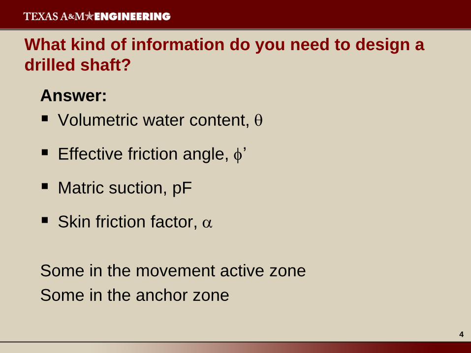
What kind of information do you need to design a
drilled shaft?
Answer:
Volumetric water content,
Effective friction angle, ’
Matric suction, pF
Skin friction factor,
Some in the movement active zone
Some in the anchor zone
UPLIFT
ANCHOR
ZONE
REINFORCING MOVEMENT
ACTIVE ZONE
SHRINKAGE
ANCHOR
ZONE
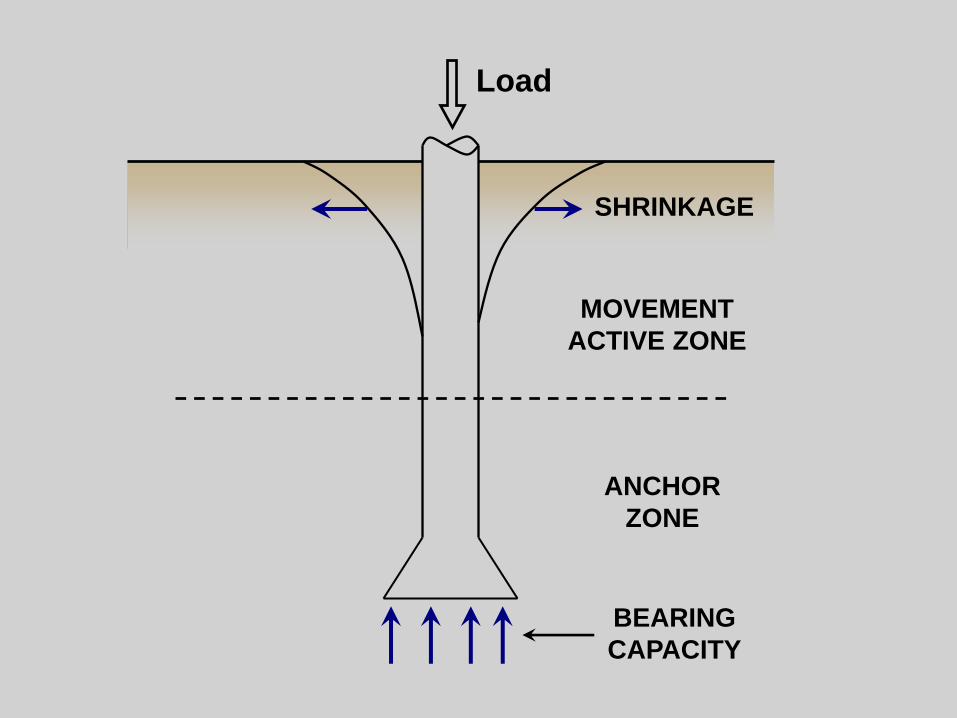
Load
BEARING
CAPACITY
MOVEMENT
ACTIVE ZONE
7
What conditions do you need to design for?
Uplift (soil gets wetter)
Bearing capacity (soil gets drier)
8
What other soils information will you need and
where do you get it?
Thornthwaite moisture index
(for deep water tables)
(map of TMI)
Water content, Atterberg limits, dry unit weight,
strength at or below the water table
(for shallow water tables)
Boring Log
Natural resources conservation service county
soil map
9
Thornthwaite Moisture Index (TMI, 1948)
100 60
p
R DEFTMI
E
R = runoff moisture depth
DEF =deficit moisture depth
Ep = evapotranspiration
10
Suction Distribution with Depth
Dry Season
(-) Suction Ground Surface
Wet Season
Equilibrium
Depth
11
12
13
14
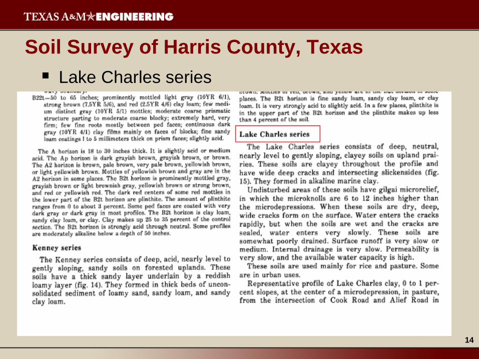
Soil Survey of Harris County, Texas
Lake Charles series
15
Lake Charles
series, cont.
16
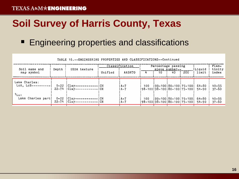
Soil Survey of Harris County, Texas
Engineering properties and classifications
17
Soil Survey of Harris County, Texas
Engineering test data
18
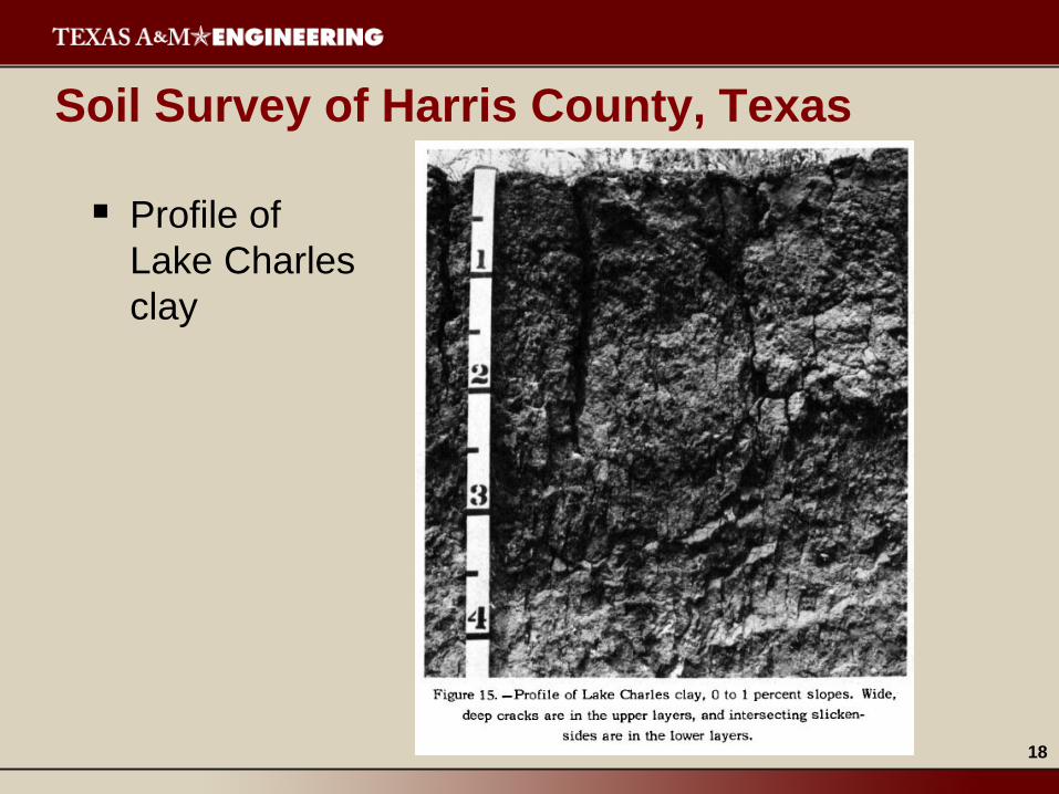
Soil Survey of Harris County, Texas
Profile of
Lake Charles
clay
19
Geotechnical Study Report No. 11-700E
Plan of Borings
20
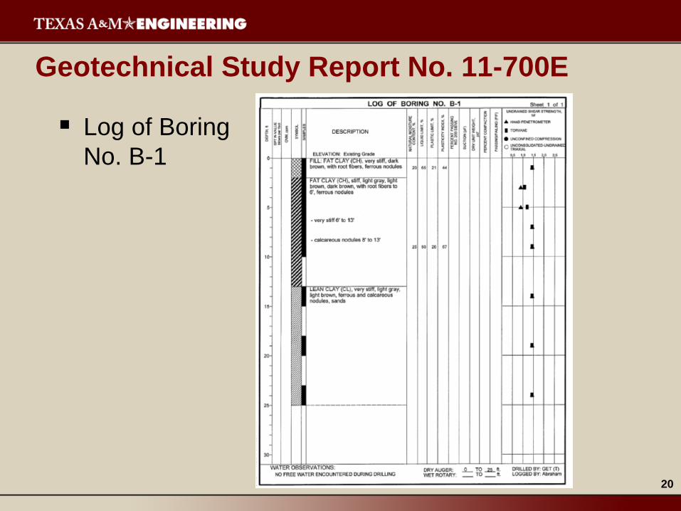
Geotechnical Study Report No. 11-700E
Log of Boring
No. B-1
21
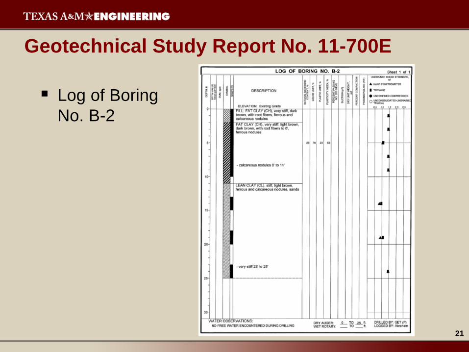
Geotechnical Study Report No. 11-700E
Log of Boring
No. B-2
22
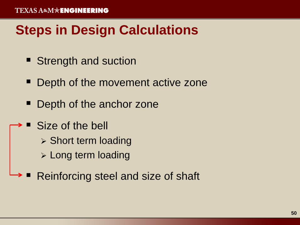
Steps in Design Calculations
Strength and suction
Depth of the movement active zone
Depth of the anchor zone
Size of the bell
Short term loading
Long term loading
Reinforcing steel and size of shaft
23
Strength and Suction
Input (in movement active and anchor zones)
Atterberg limits
Water content
Dry unit weight
Unconfined compressive strength in psi, tsf, or psf
Skin friction stress coefficient
Output (in movement active and anchor zones)
Effective friction angle
Volumetric water content
Total unit weight
Present matric suction
Future matric suction
Skin friction stress
24
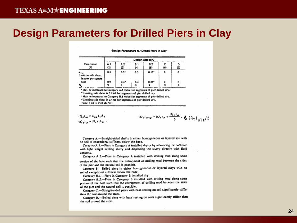
Design Parameters for Drilled Piers in Clay
25
Design Category
Parameter A.1 A.2 B.1 B.2
0.5 0.3 0.3 0.15
Side Shear
limit, tsf 0.9 0.4 0.4 0.25
A: straight-sided shafts
B: belled piers
* From Reese, Touma, and O’Neill
26
Correlation between ’ and PI
27
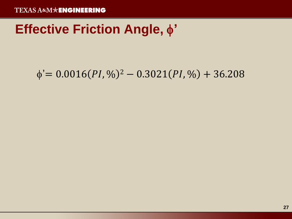
Effective Friction Angle, ’
’= 0.0016 𝑃𝐼, % 2 − 0.3021 𝑃𝐼, % + 36.208
28
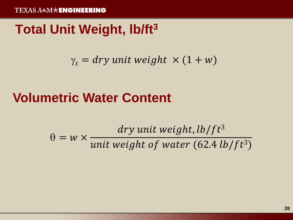
Total Unit Weight, lb/ft3
𝑡 = 𝑑𝑟𝑦 𝑢𝑛𝑖𝑡 𝑤𝑒𝑖𝑔ℎ𝑡 × (1 + 𝑤)
Volumetric Water Content
= 𝑤 ×𝑑𝑟𝑦 𝑢𝑛𝑖𝑡 𝑤𝑒𝑖𝑔ℎ𝑡, 𝑙𝑏/𝑓𝑡3
𝑢𝑛𝑖𝑡 𝑤𝑒𝑖𝑔ℎ𝑡 𝑜𝑓 𝑤𝑎𝑡𝑒𝑟 (62.4 𝑙𝑏/𝑓𝑡3)
29
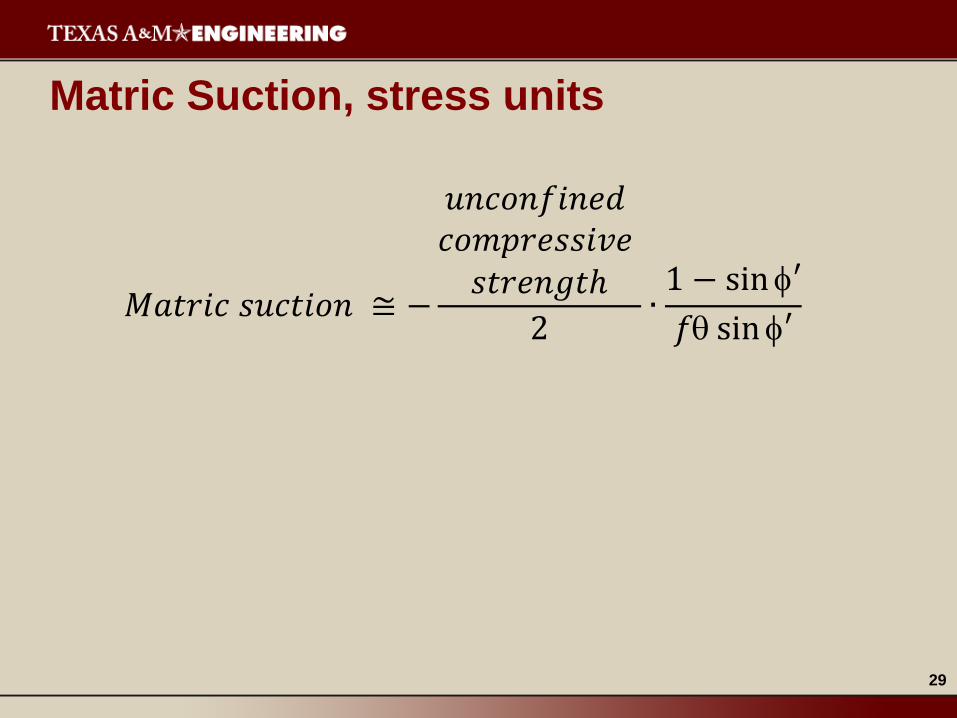
Matric Suction, stress units
𝑀𝑎𝑡𝑟𝑖𝑐 𝑠𝑢𝑐𝑡𝑖𝑜𝑛 ≅ −
𝑢𝑛𝑐𝑜𝑛𝑓𝑖𝑛𝑒𝑑 𝑐𝑜𝑚𝑝𝑟𝑒𝑠𝑠𝑖𝑣𝑒
𝑠𝑡𝑟𝑒𝑛𝑔𝑡ℎ
2∙
1 − sin ′
𝑓 sin ′
30
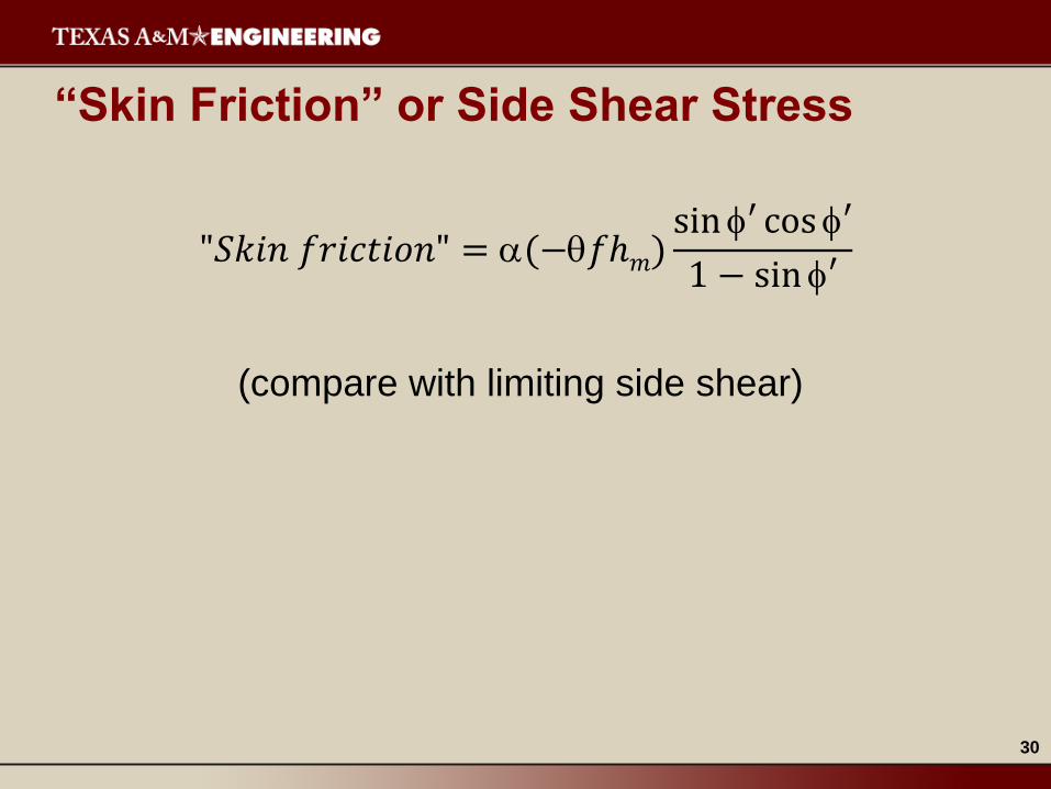
“Skin Friction” or Side Shear Stress
"𝑆𝑘𝑖𝑛 𝑓𝑟𝑖𝑐𝑡𝑖𝑜𝑛" = (−𝑓ℎ𝑚)sin ′ cos ′
1 − sin ′
(compare with limiting side shear)
31
Calculation – Strength and Suction
32
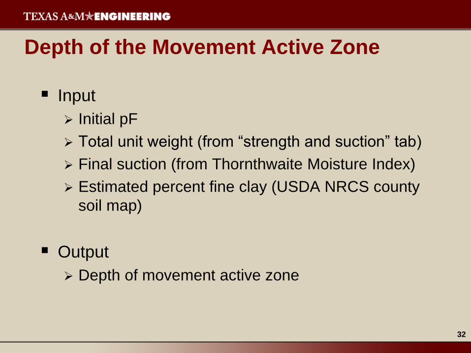
Depth of the Movement Active Zone
Input
Initial pF
Total unit weight (from “strength and suction” tab)
Final suction (from Thornthwaite Moisture Index)
Estimated percent fine clay (USDA NRCS county
soil map)
Output
Depth of movement active zone
33
Calculation – Depth of the Movement Active Zone
34
Formation of Suction vs. Pressure vs. Volume
Surface
35
Equation of a Horizontal Path on the Surface
∆𝑉
𝑉= −ℎ𝑙𝑜𝑔
ℎ𝑓
ℎ𝑖
− log𝑓
𝑖
At the depth of the movement active zone
∆𝑉
𝑉= 0
36
Percent Volume Change
Below this
depth,
pressure
reduces
volume
change
zi
zA (depth of
movement
active
zone)
0 100
zi ≅ 80 cm
zi ≅ 2.63 ft
37
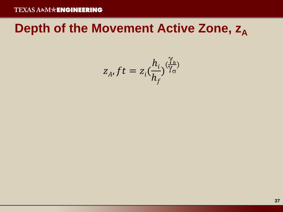
Depth of the Movement Active Zone, zA
𝑧𝐴, 𝑓𝑡 = 𝑧𝑖(ℎ𝑖
ℎ𝑓
)(
ℎ
)
38
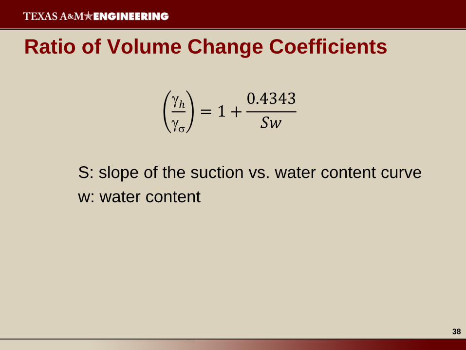
Ratio of Volume Change Coefficients
ℎ
= 1 +
0.4343
𝑆𝑤
S: slope of the suction vs. water content curve
w: water content
39
Estimate of Sw
𝑆𝑤 = 𝑝𝐹 − 5.622 − 0.0041(% 𝑓𝑖𝑛𝑒 𝑐𝑙𝑎𝑦)
40
Design Procedure for
Pavements on
Expansive Soils
Report 0-4518-1
41
Depth of the Anchor Zone
Input
Depth of the movement active zone
Skin friction stress (from “strength and suction” tab)
Trial diameter of pier shaft
Output
Depth of the anchor zone
Depth of pier
Maximum tensile force in pier shaft
Required area of reinforcing steel
42
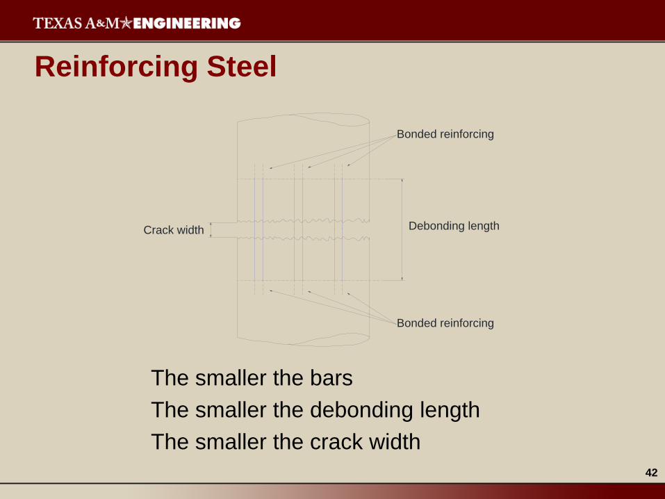
Reinforcing Steel
The smaller the bars
The smaller the debonding length
The smaller the crack width
Bonded reinforcing
Bonded reinforcing
Debonding lengthCrack width
43
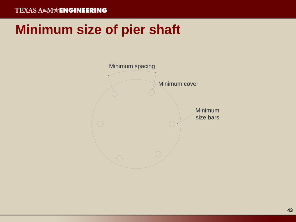
Minimum size of pier shaft
Minimum
size bars
Minimum cover
Minimum spacing
44
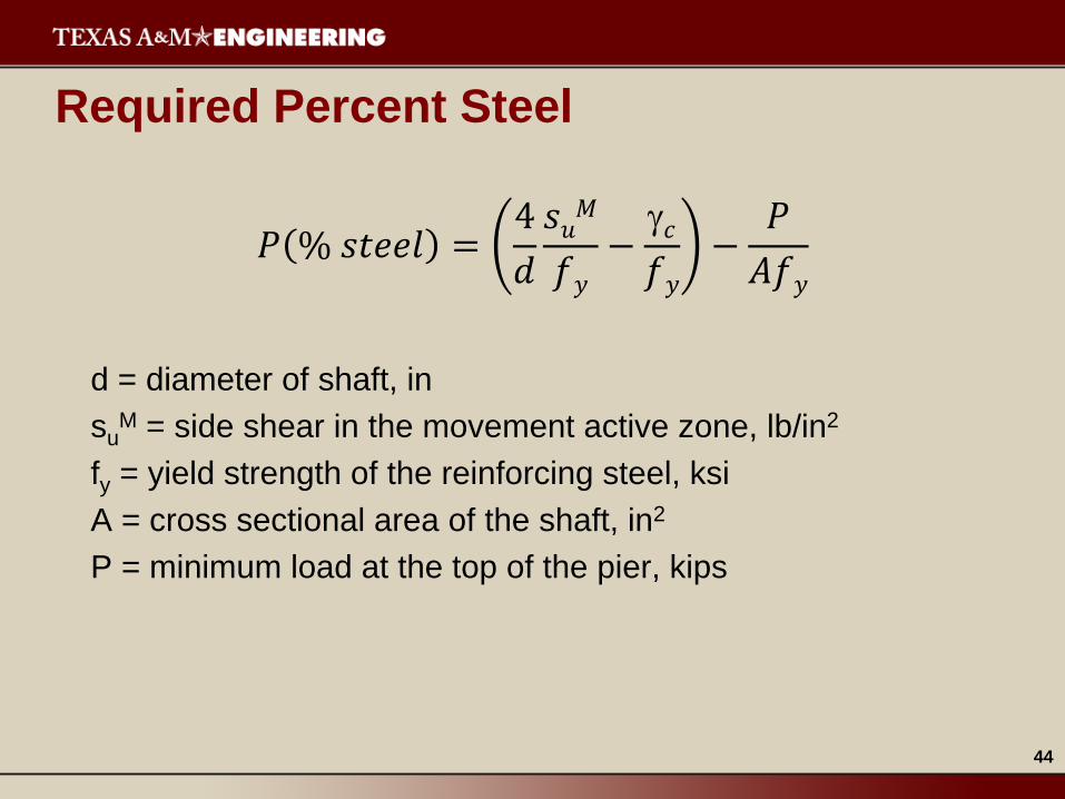
Required Percent Steel
𝑃 % 𝑠𝑡𝑒𝑒𝑙 =4
𝑑
𝑠𝑢𝑀
𝑓𝑦
−𝑐
𝑓𝑦
−𝑃
𝐴𝑓𝑦
d = diameter of shaft, in
suM = side shear in the movement active zone, lb/in2