architectures are proposed using parallel prefix adders. Instead
of using dual Ripple Carry Adders (RCA), parallel prefix adder
i.e., Brent Kung (BK) adder is used to design Regular Linear
CSA. Adders are the basic building blocks in digital integrated
circuit based designs. Ripple Carry Adder (RCA) gives the most
compact design but takes longer computation time. The time
critical applications use Carry Look-ahead scheme (CLA) to
derive fast results but they lead to increase in area. Carry Select
Adder is a compromise between RCA and CLA in term of area
and delay. Delay of RCA is large therefore we have replaced it
with parallel prefix adder which gives fast results. In this paper,
structures of 16-Bit Regular Linear Brent Kung CSA, Modified
Linear BK CSA, Regular Square Root (SQRT) BK CSA and
Modified SQRT BK CSA are designed. Power and delay of all
these adder architectures are calculated at different input
voltages. The results depict that Modified SQRT BK CSA is
better than all the other adder architectures in terms of power
but with small speed penalty. The designs have been synthesized
at 45nm technology using Tanner EDA tool.
Keywords- Brent Kung (BK) adder, Ripple Carry Adder
(RCA), Regular Linear Brent Kung Carry Select Adder,
Modified Linear BK Carry Select Adder, Regular Square Root
(SQRT) BK CSA and Modified SQRT BK CSA.
I. INTRODUCTION
An adder is a digital circuit that performs addition of numbers. In many computers and other kinds of processors, adders are used not only in the arithmetic logic unit, but also in other parts of the processor, where they are used to calculate addresses, table indices, and similar operations. Addition usually impacts widely the overall performance of digital systems and an arithmetic function. Adders are used in multipliers, in DSP to execute various algorithms like FFf, FIR and IlR. Millions of instructions per second are performed in microprocessors using adders. So, speed of operation is the most important constraint. Design of low power, high speed data path logic systems are one of the most essential areas of research in VLSI. In CSA, all possible values of the input carry i.e. 0 and 1 are defined and the result is evaluated in advance. Once the real value of the carry is known the result can be easily selected with the help of a multiplexer stage. Conventional Carry Select Adder [1] is designed using dual Ripple Carry Adders (RCAs) and then there is a multiplexer stage. Here, one RCA (Cin=l) is replaced by brent kung adder. As, RCA (for Cin=O) and Brent Kung adder (for Cin=l)
consume more chip area, so an add-one scheme i.e., Binary to
Excess-l converter is introduced. Also the square root adder architectures of CSA [2] are designed using brent kung adder in order to reduce the power and delay of adder.
In this paper, Modified Square Root Carry select Adder using Brent Kung adder is proposed using single BK and BEC instead of dual RCAs in order to reduce the power consumption with small penalty in speed.
This paper is organized as follows: In section 2, parallel prefix adders are illustrated. Section 3 explains Regular Linear BK CSA and section 4 give details of Modified Linear BK CSA. In section 5, Regular Square Root BK CSA is elucidated. The structure of Modified Square Root BK Carry Select Adder is enlightened in Section 6. Simulation Results and comparison are evaluated in section 7 and section 8 concludes.
II. PARALLEL PREFIX ADDERS
Parallel prefix adders [3] are used to speed up the binary additions as they are very flexible. The structure of Carry Look Ahead Adder (CLA) is used to obtain parallel prefix adders [4] . Tree structures are used to increase the speed [5] of arithmetic operation. Parallel prefix adders are used for high performance arithmetic circuits in industries as they increase the speed of operation. The construction of parallel prefix adder [6] involves three stages: 1. Pre- processing stage
2. Carry generation network
3. Post processing stage
Pre-possessing stage Generate and propagate signals to each pair of inputs A and
B are computed in this stage. These signals are given by the following equations: Pi=Ai xor Bi (1) Gi=Ai and Bi (2)
Carry generation network In this stage, we compute carries equivalent to each bit.
Implementation of these operations is carried out in parallel. After the computation of carries in parallel they are segmented into smaller pieces. Carry propagate and generate are used as intermediate signals which are given by the logic equations 3& 4:
2015 International Conference on VLSI Systems, Architecture, Technology and Applications (VLSI-SATA)
CPi:j=Pi:k+l and Pk:j CGi:j=Gi:k+l or (Pi:k+l and Gk:j)
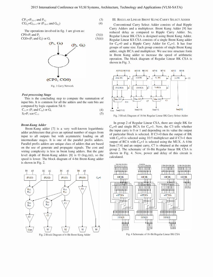
The operations involved in fig. 1 are given as: CPO=Pi and Pj CGO=(Pi and Gj) or Gi
(Pi. ' Gi)
(CPO . COO)
Fig. I Carry Network
Post processing Stage
(3) (4)
(3(i)) (3(ii) )
This is the concluding step to compute the summation of input bits. It is common for all the adders and the sum bits are computed by logic equation 5& 6: Ci-1= (Pi and Cin ) or Gi (4) Si=Pi xor Ci-1 (5)
Brent-Kung Adder Brent-Kung adder [7] is a very well-known logarithmic
adder architecture that gives an optimal number of stages from input to all outputs but with asymmetric loading on all intermediate stages. It is one of the parallel prefix adders. Parallel prefix adders are unique class of adders that are based on the use of generate and propagate signals. The cost and wiring complexity is less in brent kung adders. But the gate level depth of Brent-Kung adders [8] is 0 (log2(n)), so the speed is lower. The block diagram of 4-bit Brent-Kung adder is shown in Fig. 2.
B3 A3 B2 A1
Fig. 2 Block Diagram of 4-Bit Brent Kung Adder
III. REGULAR LINEAR BRENT KUNG CARRY SELECT ADDER
Conventional Carry Select Adder consists of dual Ripple Carry Adders and a multiplexer. Brent Kung Adder [9] has reduced delay as compared to Ripple Carry Adder. So, Regular Linear BK CSA is designed using Brent Kung Adder. Regular Linear KS CSA consists of a single Brent Kung adder for Cin=O and a Ripple Carry Adder for Cin=1. It has four groups of same size. Each group consists of single Brent Kung adder, single RCA and multiplexer. We use tree structure form in Brent Kung adder to increase the speed of arithmetic operation. The block diagram of Regular Linear BK CSA is shown in Fig. 3.
Cout Sum{15:12] Sum{1l:8] Sum[7:4]
Fig. 3 Block Diagram of 16-bit Regular Linear BK Carry Select Adder
co
In group 2 of Regular Linear CSA, there are single BK for Cin=O and single RCA for Cin=1. Now, the C3 tells whether the input carry is 0 or 1 and depending on its value the output of particular block is selected. If C3=0 then the output of BK with Cin=O is selected using 10:5 multiplexer and if C3=1 then output of RCA with Cin=l is selected using the MUX. A 4-bit Sum [7:4] and an output carry, C7 is obtained at the output of group 2. The schematic of 16-Bit Regular linear BK CSA is shown in Fig. 4. Now, power and delay of this circuit is calculated.
('HQUHI)(R 0 ........... CtI!.I>(,,)to.) �
Fig. 4 Schematic of 16-Bit Regular Linear BK CSA
2015 International Conference on VLSI Systems, Architecture, Technology and Applications (VLSI-SATA)
IV. MODIFIED LINEAR BRENT KUNG CARRY SELECT ADDER
Regular Linear Brent Kung Carry Select Adder uses single Ripple Carry Adder (RCA) for Cin=O and brent kung adder for Cin=l and is therefore area-consuming. So, different add-one schemes like Binary to Excess- 1 Converter (BEC) have been introduced. Using BEC, Regular Linear BK CSA is modified in order to obtain a reduced area and power consumption. Binary to Excess-l converter is used to add 1 to the input numbers. So, here Brent Kung adder with Cin=1 will be replaced by BEC because it require less number of logic gates for its implementation so the area of circuit is less. A circuit of 4-bit BEC and truth table is shown in Fig. 5 and Table I respectively.
B3 B2 BI BO
B3 B O
�t X3 X2 XI XO
X3 X2 X l XO
Fig. 5 4-bit Binary to Excess-I code Converter
The Boolean expressions of 4-bit BEC are listed below, (Note: functional symbols, - NOT, & AND, /\ XOR). XO = -BO Xl = BO (l )/\Bl X2 = B2 /\ (BO & Bl ) X3 = B3 /\ (BO & B 1 & B2)
TABLE I. TRUTH TABLE OF 4-BIT BINARY To EXCESS-I CONVERTER
Linear Modified BK CSA is designed using Brent Kung adder for Cin=O and Binary to Excess-l Converter for Cin=l in order to reduce the area and power consumption with small speed penalty. Linear Modified BK CSA consists of 4 groups. Each group consists of single BK adder, BEC and multiplexer. The block diagram of Linear Modified BK CSA is shown in Fig. 6.
Cout Sum(lS:12) Sum(Il:8) Sum(7:4) Sum(3:O) Fig.6 B)ock Diagram of 16-bit Linear Modified BK Carry Select Adder
co
To replace the N-bit Brent Kung adder, a N+l bit BEC is required. The importance of BEC logic comes from the large silicon area reduction when designing Linear Modified BK CSA for large number of bits. The schematic of Linear Modified BK CSA is shown in Fig. 7.
Fig. 7 Schematic of 16-Bit Linear Modified BK CSA
V. REGULAR SQUARE ROOT BRENT KUNG CARRY SELECT ADDER
Regular Linear Brent Kung Carry Select Adder consumes large area and to reduce its area a new design of adder is used i.e. Regular Square Root Brent Kung Carry Select Adder. Regular Square Root BK CSA has 5 groups of different size brent kung adder. Each group contains single BK for Cin=O, RCA for Cin=1 and MUX. The block diagram of the 16-bit regular SQRT BK CSA is shown in Fig. 8. High area usage and high time delay are the two main disadvantages of Linear Carry Select Adder. These disadvantages of linear carry select adder can be rectified by SQRT CSA [10]. It is an improved version of linear CSA. The time delay of the linear adder can decrease, by having one more input into each set of adders than in the previous set. This is called a Square Root Carry Select Adder.
2015 International Conference on VLSI Systems, Architecture, Technology and Applications (VLSI-SATA)
Fig. 8 Block Diagram of l6-bit Regular Square Root BK Carry Select Adder
The schematic of 16-bit Regular Square Root BK Carry Select Adder is shown in Fig. 9. There are 5 groups in Regular Square Root BK Carry Select Adder [11] . Here single Brent Kung adder is used for Cin=O and ripple carry adder is used for Cin=l and then there is a multiplexer stage. Due to the presence of RCA and BK, this circuit consumes large area.
(')/A1,Q/JI1Il1,Q O ...... t-- ...... c:tII�w� ... �
Fig. 9 Schematic of l6-Bit Regular SQRT BK CSA
VI. MODIFIED SQUARE ROOT BRENT KUNG CARRY SELECT
ADDER
Modified Square Root Brent Kung Carry Select Adder has been designed using Brent kung adder for Cin=O and BEC for Cin=l and then there is a multiplexer stage. It has 5 groups of different size brent kung adder and Binary to Excess-l Converter (BEC). BEC is used to add 1 to the input numbers. Less number of logic gates are used to design BEC as compared to RCA therefore it consumes less area. The block diagram of the 16-bit modified Square Root BK Carry Select Adder is shown in Fig. 10.
Fig. 10 Block Diagram of 16-bit Modified SQRT BK CSA
co
Each group contains one BK, one BEC and MUX. For NBit Brent Kung adder, N+ 1 Bit BEC is used. Fig. 11 shows the schematic of 16-Bit Modified SQRT CSA. Power consumption and delay of this adder is calculated for 16-Bit word size.
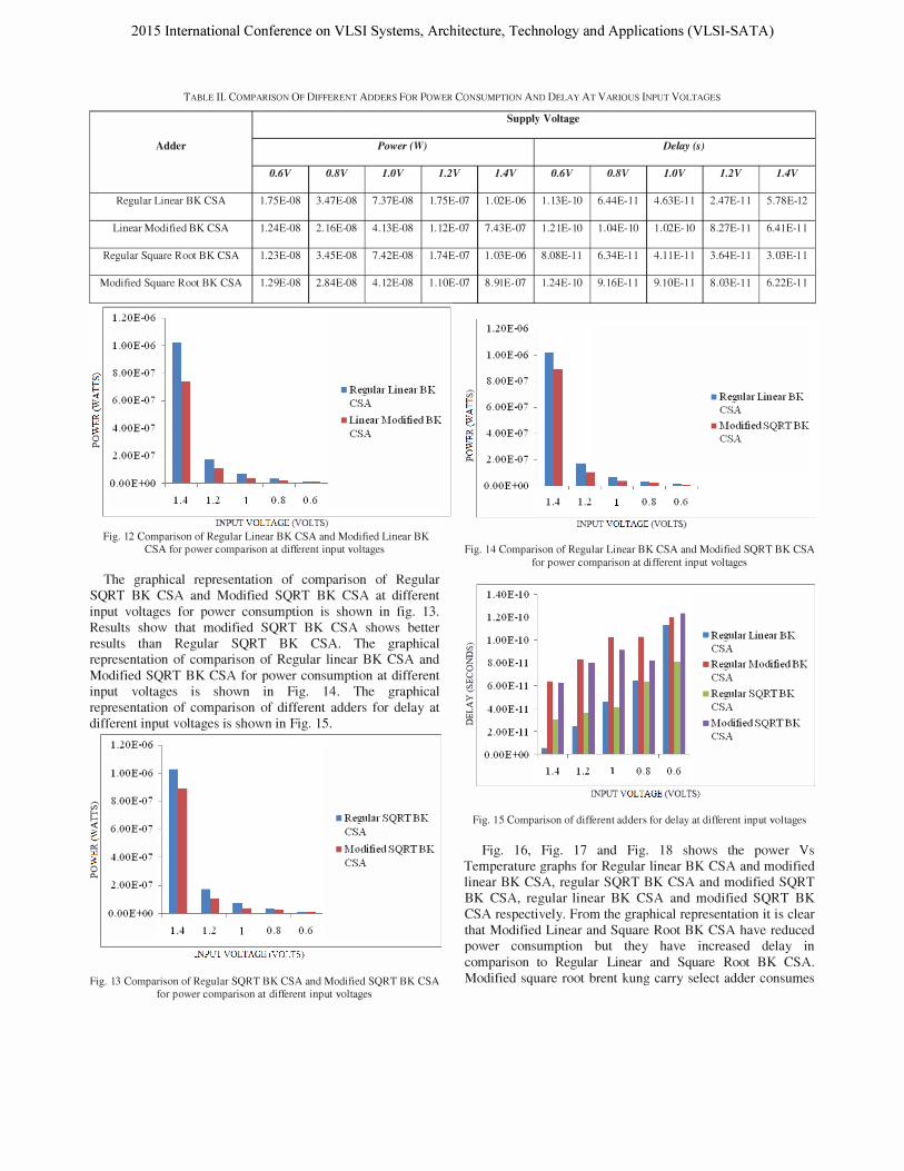
Various adders were designed in Tanner EDA version 13.0 tool using Predictive Model Beta Version 45nm CMOS technology. Power consumption and delay of various adders like Regular Linear BK CSA, Regular SQRT BK CSA, Modified Linear BK CSA and Modified SQRT BK CSA has been calculated for 16-Bit word size. The comparison of various adders for different parameters like delay and power consumption is shown in Table II. The result analysis shows that Modified Square Root Brent kung Carry Select Adder shows better results than all the other adder architectures in terms of power consumption at different input voltages but with a small speed penalty. The graphical representation of comparison of Regular Linear BK CSA and Modified Linear BK CSA for different input voltages for power consumption is shown in fig. 12. Results show that modified linear BK CSA shows better results than Regular Linear BK CSA.
2015 International Conference on VLSI Systems, Architecture, Technology and Applications (VLSI-SATA)
TABLE II. COMPARISON OF DIFFERENT ADDERS FOR POWER CONSUMPTION AND DELAY AT VARIOUS INPUT VOLTAGES
Supply Voltage
Adder Power(W) Delay (s)
O.6V O.8V 1.0V 1.2V l.4V O.6V O.8V 1.0V 1.2V l.4V
Regular Linear BK CSA l.7SE-OS 3.47E-OS 7.37E-OS 1.7SE-07 I.02E-06 I.13E-1O 6.44E- l l 4.63E-l l 2.47E-l l S.7SE-l2
Linear Modified BK CSA 1.24E-OS 2.16E-OS 4.13E-OS 1.12E-07 7.43E-07 I.21E-1O I.04E-1O I.02E-1O S.27E-II 6.4IE-l l
Regular Square Root BK CSA 1.23E-OS 3.4SE-OS 7.42E-OS 1.74E-07 I.03E-06 S.OSE-II 6.34E-l l 4.IIE-l l 3.64E-II 3.03E-l l
Modified Square Root BK CSA 1.29E-OS 2.S4E-OS 4.12E-OS l.lOE-07 S.9lE-07 1.24E-1O 9.16E-l l 9.IOE-l l S.03E-II 6.22E-l l
(i)'
� � 0 ""
1.20E-06
1.00E-06
8.00E-07
• Regular Linear BK 6.00E-07 CSA
• Linear Modified BK 4.00E-07
CSA
2.00E-07
O.OOE+OO
1.4 1.2 0.8 0.6
INPUT VOLTAGE (VOLTS)
Fig. l2 Comparison of Regular Linear BK CSA and Modified Linear BK CSA for power comparison at different input voltages
The graphical representation of comparison of Regular SQRT BK CSA and Modified SQRT BK CSA at different input voltages for power consumption is shown in fig. 13. Results show that modified SQRT BK CSA shows better results than Regular SQRT BK CSA. The graphical representation of comparison of Regular linear BK CSA and Modified SQRT BK CSA for power consumption at different input voltages is shown in Fig. 14. The graphical representation of comparison of different adders for delay at different input voltages is shown in Fig. 15.
1.20E-06
1.00E-06
(i)' 8.00E-Oi
� 6.00E-07 � '"
� 4.00E-07
0 ""
2.00E-07
O.OOE+OO
1.4 1.2 0.8 0.6
INPUT VOLTAGE (VOLTS)
• Regular SQRTBK
CSA
• Modified SQRTBK
CSA
Fig. l3 Comparison of Regular SQRT BK CSA and Modified SQRT BK CSA for power comparison at different input voltages
1.20E-06
1.00E-06
8.00E-07
(i)' • Regular Linear BK
� 6.00E-07 CSA
• Modified SQRTBK '" 4.00E-07
� CSA
0 2.00E-07 ""
O.OOE+OO
1.4 1.2 0.8 0.6
INPUT VOLTAGE (VOLTS)
Fig. 14 Comparison of Regular Linear BK CSA and Modified SQRT BK CSA for power comparison at different input voltages
(i)'
� 0 u "" � >-« ....
�
1.40E-10
1.10E-10
1.00E-10
8.00E-ll
6.00E-ll
4.00E-ll
1.00E-ll
O.OOE+OO
1.4 1.2 0.8 0.6
INPUT VOLTAGE (VOLTS)
• Regular Linear BK CSA
• Regular Moctified BK CSA
• Regular SQRTBK CSA
• Modified SQRTBK CSA
Fig. IS Comparison of different adders for delay at different input voltages
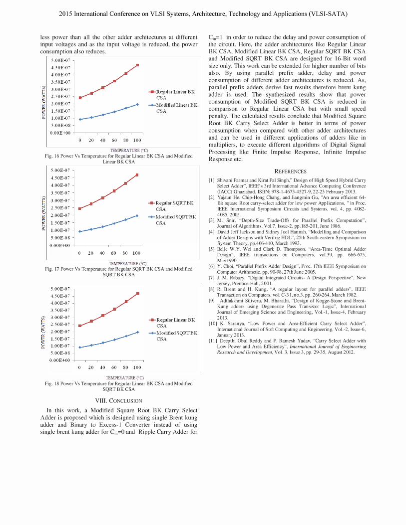
Fig. 16, Fig. 17 and Fig. 18 shows the power Vs Temperature graphs for Regular linear BK CSA and modified linear BK CSA, regular SQRT BK CSA and modified SQRT BK CSA, regular linear BK CSA and modified SQRT BK CSA respectively. From the graphical representation it is clear that Modified Linear and Square Root BK CSA have reduced power consumption but they have increased delay in comparison to Regular Linear and Square Root BK CSA. Modified square root brent kung carry select adder consumes
2015 International Conference on VLSI Systems, Architecture, Technology and Applications (VLSI-SATA)
less power than all the other adder architectures at different input voltages and as the input voltage is reduced, the power consumption also reduces.
5.00E-07
4.50E-07
4.00E-07
3.50E-07
V:l 3.00E-07
� � o p..
2.50E-07
2.00E-07
l.50E-07
l.00E-07
5.00E-08
o .00E-t()0 +--,----,----,--,--,------, o 20 40 60 80 100
_Reglliar Linear BK CSA
__ Modified Linear BK CSA
TEMPERATURE ('C)
Fig. 16 Power Vs Temperature for Regular Linear BK CSA and Modified Linear BK CSA
5.00E-07
4.50E-07
4.00E-07
3.50E-07
rii 3.00E-07
� � o p..
2.50E-07
2.00E-07
l.50E-07
l.00E-07
5.00E-OS
0.00 E -t()0 +-----,---,--,--,----,--, o 20 40 60 80 100
TEMPERATURE (0C)
_ Regular SQRTBK
CSA
__ Modified SQRTBK
CSA
Fig. 17 Power Vs Temperature for Regular SQRT BK CSA and Modified SQRT BK CSA
5.00E-07
4.50E-07
4.00E-07
3.50E-07
� 3.00E-07
� � p..
2.50E-07
2.00E-07
l.50E-07
l.00E-07
5.00E-OS
o .00E-t()0 +--,------,---,---,-,-----, o 20 40 60 80 100
TEMPERATURE ('C)
_ Regular Linear BK CSA
__ lvIoclifiedSQRTBK CSA
Fig. 18 Power Vs Temperature for Regular Linear BK CSA and Modified SQRT BK CSA
VIII. CONCLUSION
In this work, a Modified Square Root BK Carry Select Adder is proposed which is designed using single Brent kung adder and Binary to Excess-l Converter instead of using single brent kung adder for Cin=O and Ripple Carry Adder for
Cin=l in order to reduce the delay and power consumption of the circuit. Here, the adder architectures like Regular Linear BK CSA, Modified Linear BK CSA, Regular SQRT BK CSA and Modified SQRT BK CSA are designed for 16-Bit word size only. This work can be extended for higher number of bits also. By using parallel prefix adder, delay and power consumption of different adder architectures is reduced. As, parallel prefix adders derive fast results therefore brent kung adder is used. The synthesized results show that power consumption of Modified SQRT BK CSA is reduced in comparison to Regular Linear CSA but with small speed penalty. The calculated results conclude that Modified Square Root BK Carry Select Adder is better in terms of power consumption when compared with other adder architeclures and can be used in different applications of adders like in multipliers, to execute different algorithms of Digital Signal Processing like Finite Impulse Response, Infinite Impulse Response etc.
REFERENCES
[I] Shivani Parmar and Kirat Pal Singh," Design of High Speed Hybrid Carry Select Adder", IEEE's 3rd International Advance Computing Conference (IACC) Ghaziabad, ISBN: 978-1-4673-4527-9,22-23 February 2013.
[2] Yajaun He, Chip-Hong Chang, and Jiangmin Gu, "An area efficient 64-Bit square Root carry-select adder for low power Applications, " in Proc. IEEE International Symposium Circuits and Systems, vol. 4, pp. 4082-4085,2005.
[3] M. Snir, "Depth-Size Trade-Offs for Parallel Prefix Computation", Journal of Algorithms, Vo!.7, Issue-2, pp.185-201, June 1986.
[4] David Jeff Jackson and Sidney Joel Hannah, "Modelling and Comparison of Adder Designs with Verilog HDL", 25th South-eastern Symposium on System Theory, pp.406-4tO, March 1993.
[5] Belle W.Y. Wei and Clark D. Thompson, "Area-Time Optimal Adder Design", IEEE transactions on Computers, vo!.39, pp. 666-675, May1990.
[6] Y. Choi, "Parallel Prefix Adder Design", Proc. 17th IEEE Symposium on Computer Arithmetic, pp. 90-98, 27th June 2005.
[7] J. M. Rabaey, "Digital Integrated Circuits- A Design Perspective", New Jersey, Prentice-Hall, 2001.
[8] R. Brent and H. Kung, "A regular layout for parallel adders", IEEE Transaction on Computers, vol. C-31, no.3, pp. 260-264, March 1982.
[9] Adilakshmi Siliveru, M. Bharathi, "Design of Kogge-Stone and BrentKung adders using Degenerate Pass Transistor Logic", International Journal of Emerging Science and Engineering, Vol.-I, Issue-4, February 2013.
[to] K. Saranya, "Low Power and Area-Efficient Carry Select Adder", International Journal of Soft Computing and Engineering, Vol.-2, Issue-6, January 2013.
[II] Deepthi Obul Reddy and P. Ramesh Yadav, "Carry Select Adder with Low Power and Area Efficiency", lnlernalional Journal of Engineering Research and Developmenl, Vol. 3, Issue 3, pp. 29-35, August 2012.