21
Design specifications and test ... Enzo Carrone et al LEB 2001 Design specifications and test of the HMPID’s control system prototype in the ALICE experiment Enzo CARRONE [email protected]

Design specifications and test ... Enzo Carrone et alLEB 2001
Design specifications and test of the HMPID’s control system prototype in the
ALICE experiment
Enzo CARRONE

Design specifications and test ... Enzo Carrone et alLEB 2001
HMPID Control System
Design
Conclusions
Implementation and tests
Design specifications and test ... Enzo Carrone et alLEB 2001
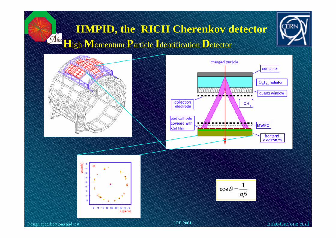
HMPID, the RICH Cherenkov detectorHigh Momentum Particle Identification Detector
Design specifications and test ... Enzo Carrone et alLEB 2001
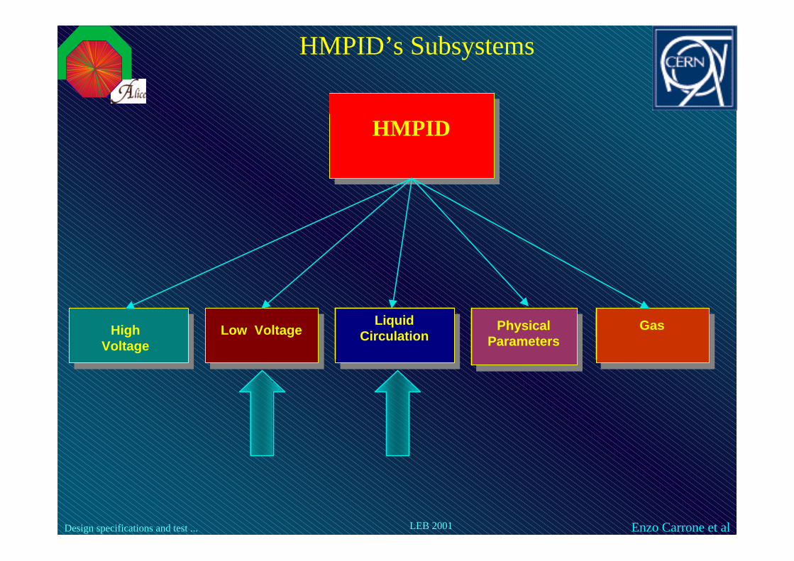
HMPID’s Subsystems
HMPID
High Voltage
Low Voltage Physical Parameters
Liquid Circulation
Gas

Design specifications and test ... Enzo Carrone et alLEB 2001
Low Voltage System
Liquid Circulation System

Design specifications and test ... Enzo Carrone et alLEB 2001
LPC = Local Process Control
HMI = Human Machine Interface
OPC = OLE for Process Control (Microsoft)
DCOM = Distributed Component Object Model (Microsoft)
LPC = Local Process Control
HMI = Human Machine Interface
OPC = OLE for Process Control (Microsoft)
DCOM = Distributed Component Object Model (Microsoft)
Software Architecture of the HMPID’s control
Design specifications and test ... Enzo Carrone et alLEB 2001
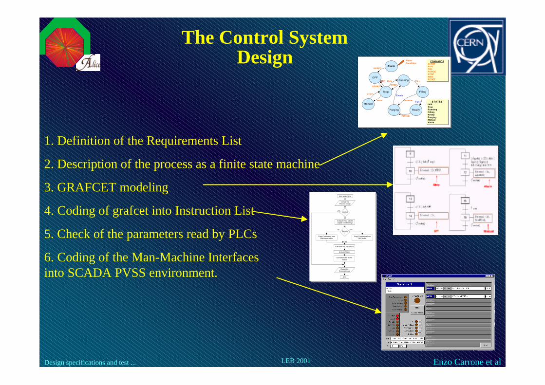
The Control System Design
1. Definition of the Requirements List
2. Description of the process as a finite state machine
3. GRAFCET modeling
4. Coding of grafcet into Instruction List
5. Check of the parameters read by PLCs
6. Coding of the Man-Machine Interfaces into SCADA PVSS environment.
Running
Filling
Purging Ready
Stop
Manual
OFF
START
RUN FILL
PURGE
STOP
MAN
STOP
Full !
Empty !
COMMANDSSTARTRUNFILLPURGESTOPMANRESET
COMMANDSSTARTRUNFILLPURGESTOPMANRESET
STATESOFFStopRunningFillingReadyPurgingManualAlarm
STATESOFFStopRunningFillingReadyPurgingManualAlarm
AlarmRESET
AlarmCondition
PURGE
OFF
Start Main Cycle
Create theProcess Image
Interlock?
Analyze Input Values(signal conditioning)
Copy Commands fromOPC buffer
Remote?
Copy Commands fromHW Inputs buffer
Calculate the Transitions
Activate States
Do Actions for ActiveStates
Output theProcess Image
End
yes
yesno
Design specifications and test ... Enzo Carrone et alLEB 2001
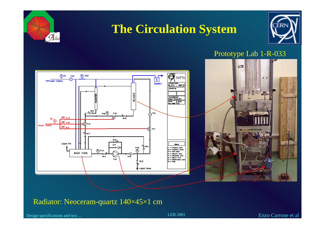
The Circulation System
Prototype Lab 1-R-033
Radiator: Neoceram-quartz 140×45×1 cm

Design specifications and test ... Enzo Carrone et alLEB 2001
The Transitions Diagram1. Definition of the Requirements List
2. Description of the process as a finite state machine
3. GRAFCET modeling
4. Coding of grafcet into Instruction List
5. Check of the parameters read by PLCs
6. Coding of the Man-Machine Interfaces into SCADA PVSS environment.
CommandsStart
Stop
Fill
Run
Radiator Purge
Header Purge
StatesStart
Off
Alarm
Fill
Run
RP
Radiator Purge
Header Purge
Purge
Design specifications and test ... Enzo Carrone et alLEB 2001
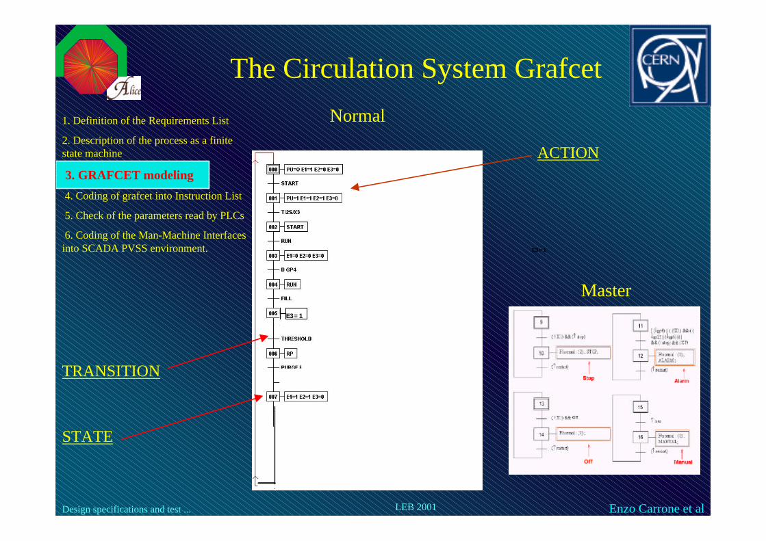
The Circulation System GrafcetNormal
Master
1. Definition of the Requirements List
2. Description of the process as a finite state machine
3. GRAFCET modeling
4. Coding of grafcet into Instruction List
5. Check of the parameters read by PLCs
6. Coding of the Man-Machine Interfaces into SCADA PVSS environment.
TRANSITION
STATE
ACTION
E3=1
E3=1
Design specifications and test ... Enzo Carrone et alLEB 2001
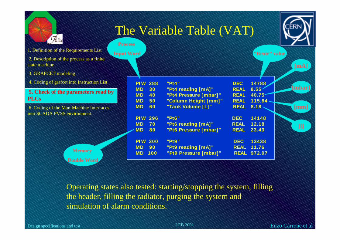
The Variable Table (VAT)
PIW 288 "Pt4" DEC 14788MD 30 "Pt4 reading [mA]" REAL 8.55MD 40 "Pt4 Pressure [mbar]" REAL 40.75MD 50 "Column Height [mm]" REAL 115.84MD 60 "Tank Volume [L]" REAL 8.18
PIW 296 "Pt6" DEC 14148MD 70 "Pt6 reading [mA]" REAL 12.18MD 80 "Pt6 Pressure [mbar]" REAL 23.43
PIW 300 "Pt9" DEC 13438MD 90 "Pt9 reading [mA]" REAL 11.76MD 100 "Pt9 Pressure [mbar]" REAL 972.07
1. Definition of the Requirements List
2. Description of the process as a finite state machine
3. GRAFCET modeling
4. Coding of grafcet into Instruction List
5. Check of the parameters read by PLCs
6. Coding of the Man-Machine Interfaces into SCADA PVSS environment.
Operating states also tested: starting/stopping the system, filling the header, filling the radiator, purging the system and simulation of alarm conditions.
Process
Input Word
Memory
Double Word
“Brute” value
[mbar]
[mm]
[l]
[mA]

Design specifications and test ... Enzo Carrone et alLEB 2001
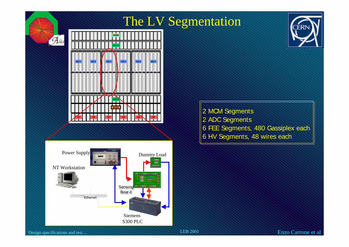
The Low Voltage System
MWPC: 150×150×8 cm
Prototype Lab 1-R-033
Design specifications and test ... Enzo Carrone et alLEB 2001
MCM1
MCM2
ADC1a
ADC1b
FEE 1 FEE 2 FEE 3 FEE 4 FEE 5 FEE 6
H1 H2 H3 H4 H5 H6
Power Supply
Siemens S300 PLC
Ethernet
SensingBoard
SensingBoard
Dummy Load
2 MCM Segments2 ADC Segments6 FEE Segments, 480 Gassiplex each6 HV Segments, 48 wires each
The LV Segmentation
NT Workstation

Design specifications and test ... Enzo Carrone et alLEB 2001
The Test Bench schematics
Eutron Power Supply:
0-8V, 20 A
Sensing Board
Dummy Load
PLC Siemens
Digital Output Module
PLC Siemens
ADC Module
Standby

Design specifications and test ... Enzo Carrone et alLEB 2001
Sensing Board
ADC Siemens UCM= 2.5V
Sensing Board
UCM= (Vin+Vo)/2 ≈ 3.9 V
Network Reduction Ratio:
A= R4/(R3+R4)= 0,325
( )4
4343
443
443
421
2
sinsin
sin
RRR
VVVRR
RVVV
RRR
VRR
RRR
RVVVV
pedsrgsengsenpedsr
gseninsssr
+−=⇒
++=
++
+−
+=−=
++
+−++
mARA
LSB
S
8,2=⋅
=δ
Single GASSIPLEX faultdetection (23 mA)
Design specifications and test ... Enzo Carrone et alLEB 2001
STATESOFFStopRunningFillingReady
COMMANDSSTARTRUNFILLPURGESTOPMANRESET
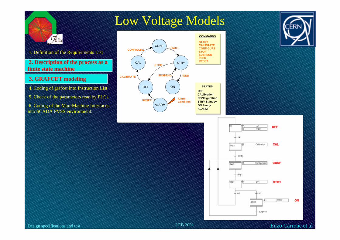
COMMANDS
STARTCALIBRATECONFIGURESTOPSUSPENDFEEDRESET
CONF
STBY
ON
CAL
OFF
CALIBRATE
CONFIGURESTART
STOP
SUSPEND FEED
ALARM
AlarmConditionRESET
STATES
OFFCALibrationCONFigurationSTBY StandbyON ReadyALARM
Low Voltage Models
1. Definition of the Requirements List
2. Description of the process as a finite state machine
3. GRAFCET modeling
4. Coding of grafcet into Instruction List
5. Check of the parameters read by PLCs
6. Coding of the Man-Machine Interfaces into SCADA PVSS environment.
Design specifications and test ... Enzo Carrone et alLEB 2001
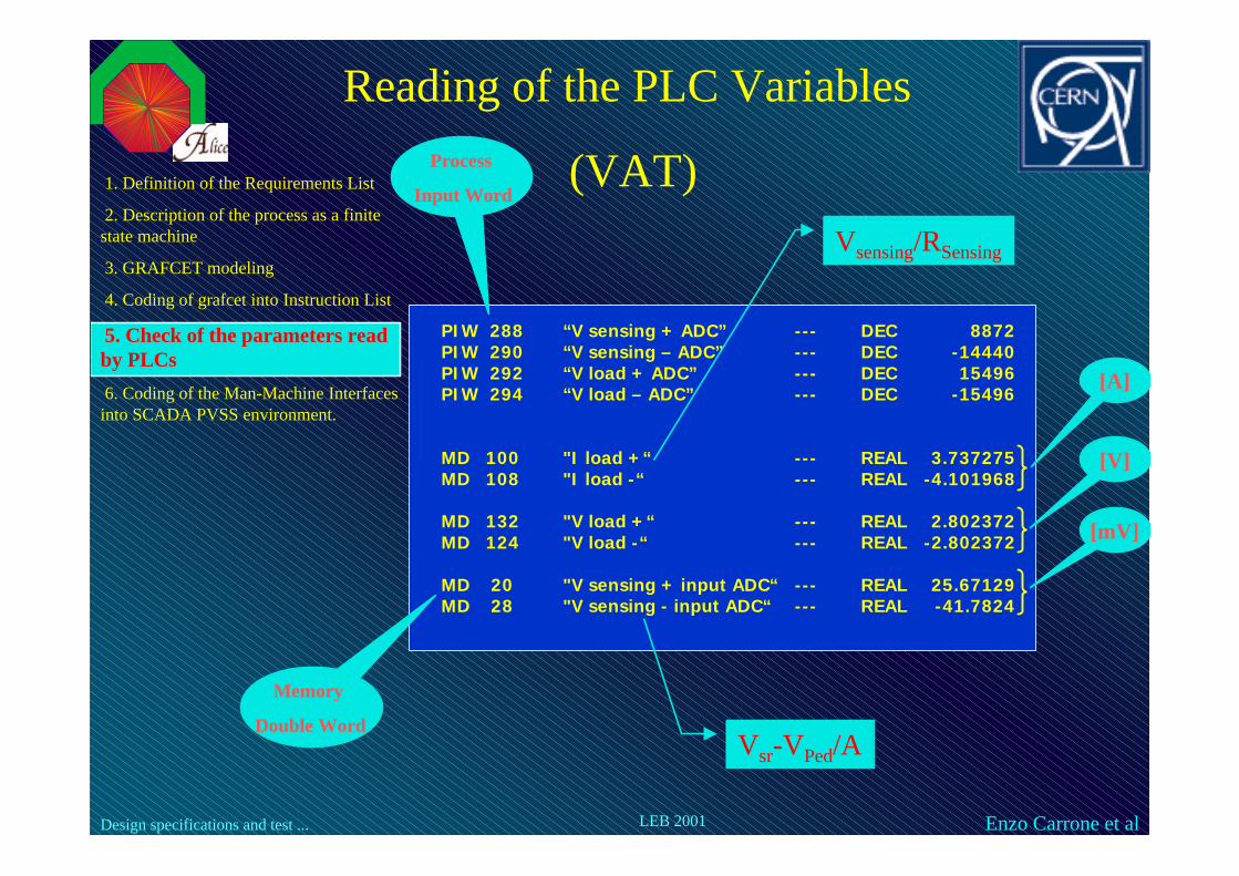
Reading of the PLC Variables
(VAT)1. Definition of the Requirements List
2. Description of the process as a finite state machine
3. GRAFCET modeling
4. Coding of grafcet into Instruction List
5. Check of the parameters readby PLCs
6. Coding of the Man-Machine Interfaces into SCADA PVSS environment.
PIW 288 “V sensing + ADC” --- DEC 8872PIW 290 “V sensing – ADC” --- DEC -14440PIW 292 “V load + ADC” --- DEC 15496PIW 294 “V load – ADC” --- DEC -15496
MD 100 "I load +“ --- REAL 3.737275MD 108 "I load -“ --- REAL -4.101968
MD 132 "V load +“ --- REAL 2.802372MD 124 "V load -“ --- REAL -2.802372
MD 20 "V sensing + input ADC“ --- REAL 25.67129MD 28 "V sensing - input ADC“ --- REAL -41.7824
Vsensing/RSensing
[V]
[mV]
[A]
Memory
Double Word
Process
Input Word
Vsr-VPed/A

Design specifications and test ... Enzo Carrone et alLEB 2001
Trend diagrams

Design specifications and test ... Enzo Carrone et alLEB 2001
SCADASupervisory Control And Data Acquisition
Man Machine Interfaces1.Definition of the Requirements List
2. Description of the process as a finite state machine
3. GRAFCET modeling
4. Coding of grafcet into Instruction List
5. Check of the parameters read by PLC
6. Coding of the Man-MachineInterfaces into SCADA PVSSenvironment.
LV Sys.LIQUID
Circ. Sys.
Design specifications and test ... Enzo Carrone et alLEB 2001
CONCLUSIONSThe methodology adopted hereby is effective and time saving:
u The Requirements List lets us fulfill the system designer’s desires
u GRAFCET lets non-specialists also understand the way the controls work (making debugging easier than ever)
u GRAFCET lets also programming the SCADA.
u The method aims to fix common bases for the whole DCS design.
Next steps:
√ Integrating the control of Liquid and Low Voltage System into acoherent, detector-oriented man-machine interface (following the JCOP frameworks philosophy)
√ Defining a systematic procedure for alarms handling
√ Defining a systematic procedure for measuring the critical parameters

Design specifications and test ... Enzo Carrone et alLEB 2001
TACK SA MYCKET !
(Thank you!)


