Cookson And Zinn (PTL) Limited Design Substantiation of PetroFast Modular Tank Unit August 2002 (F.E.A. updated 2014) (Minor update, June 2016) (Minor updates, July 2021) Cookson And Zinn (PTL) Limited, Station Road Works, Pond Hall Lane, Hadleigh, Ipswich Suffolk IP7 5PN England Tel 44 (0) 1473 825 200 Fax 44 (0) 1473 824 164 Email: [email protected]Website: www.czltd.com FTP: http://secure.czltd.com/Engineering
Transcript
Cookson And Zinn (PTL) Limited
Design Substantiation of PetroFast Modular Tank Unit
August 2002
(F.E.A. updated 2014)
(Minor update, June 2016) (Minor updates, July 2021)
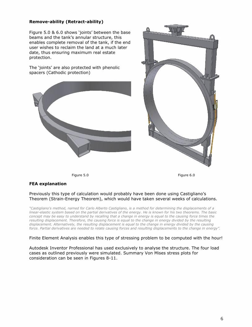
Previously this type of calculation would probably have been done using Castigliano’s
Theorem (Strain-Energy Theorem), which would have taken several weeks of calculations.
“Castigliano's method, named for Carlo Alberto Castigliano, is a method for determining the displacements of a linear-elastic system based on the partial derivatives of the energy. He is known for his two theorems. The basic concept may be easy to understand by recalling that a change in energy is equal to the causing force times the resulting displacement. Therefore, the causing force is equal to the change in energy divided by the resulting displacement. Alternatively, the resulting displacement is equal to the change in energy divided by the causing force. Partial derivatives are needed to relate causing forces and resulting displacements to the change in energy”.
Finite Element Analysis enables this type of stressing problem to be computed with the hour!
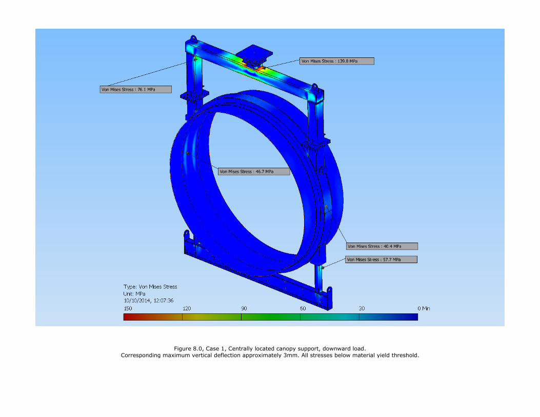
Autodesk Inventor Professional has used exclusively to analyse the structure. The four load
cases as outlined previously were simulated. Summary Von Mises stress plots for
consideration can be seen in Figures 8-11.
7
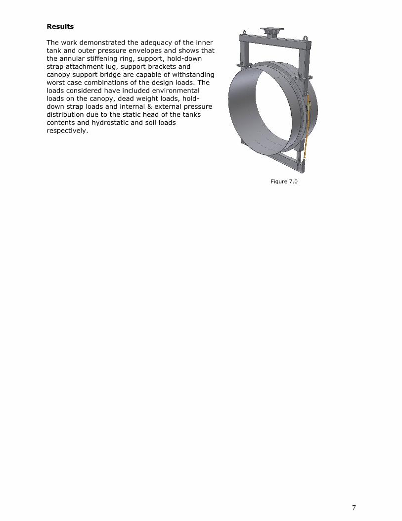
Results
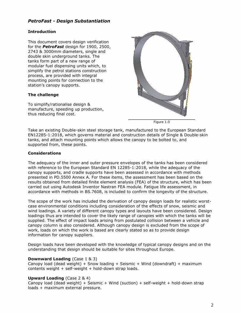
The work demonstrated the adequacy of the inner
tank and outer pressure envelopes and shows that
the annular stiffening ring, support, hold-down
strap attachment lug, support brackets and
canopy support bridge are capable of withstanding
worst case combinations of the design loads. The
loads considered have included environmental
loads on the canopy, dead weight loads, hold-
down strap loads and internal & external pressure
distribution due to the static head of the tanks
contents and hydrostatic and soil loads
respectively.
Figure 7.0
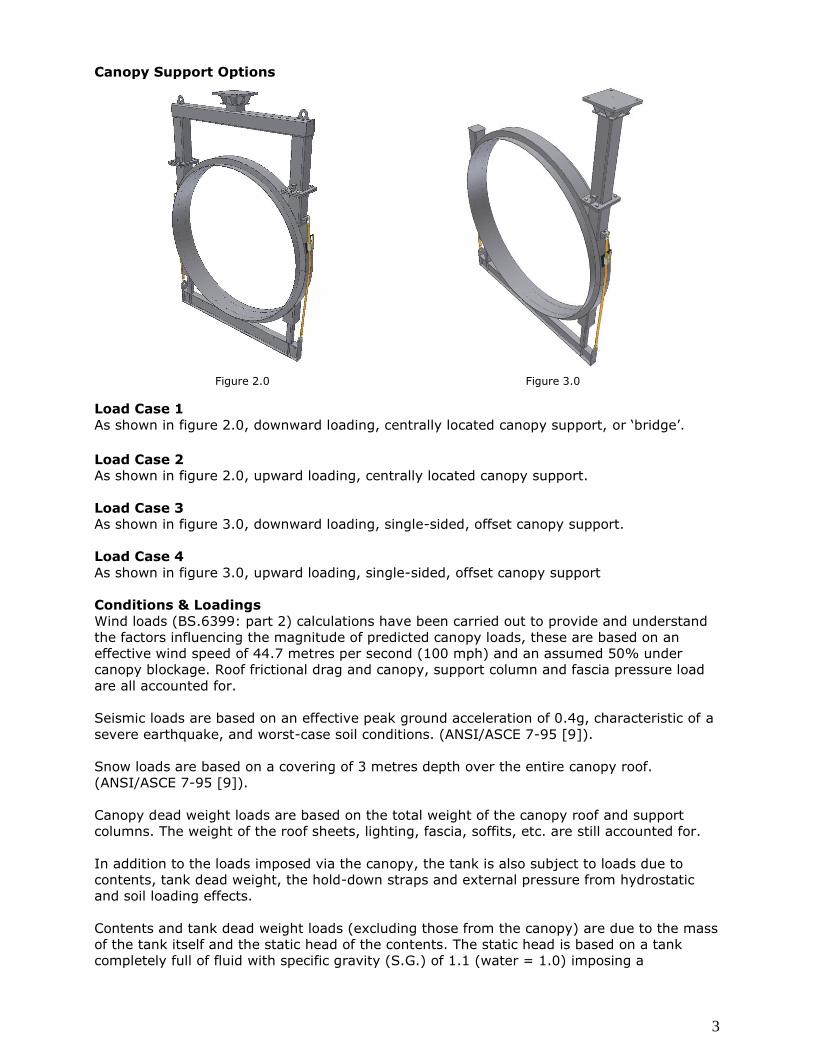
Figure 8.0, Case 1, Centrally located canopy support, downward load.
Corresponding maximum vertical deflection approximately 3mm. All stresses below material yield threshold.
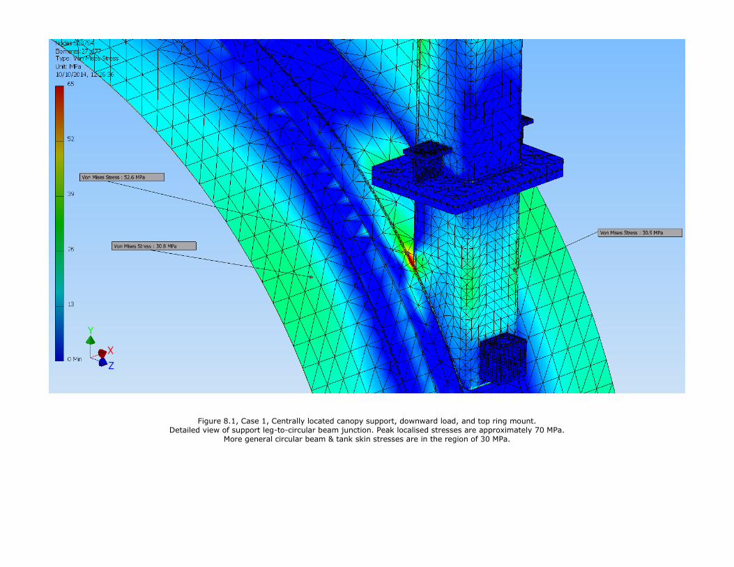
Figure 8.1, Case 1, Centrally located canopy support, downward load, and top ring mount.
Detailed view of support leg-to-circular beam junction. Peak localised stresses are approximately 70 MPa. More general circular beam & tank skin stresses are in the region of 30 MPa.
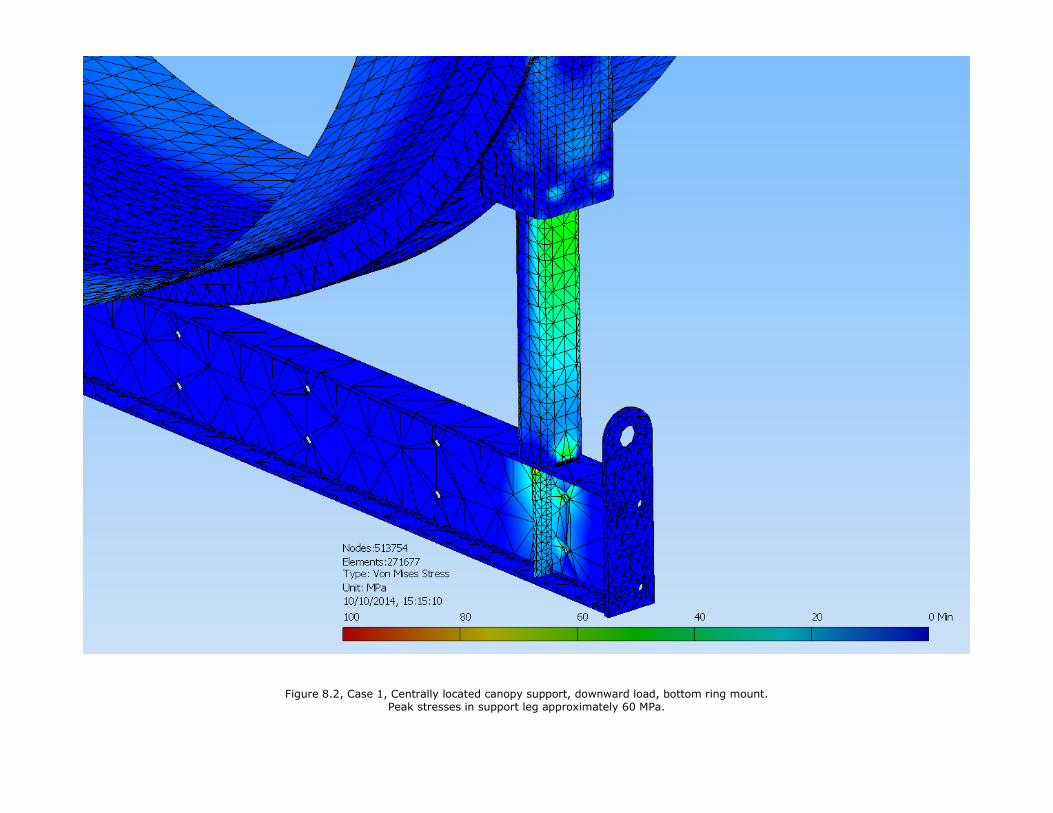
Figure 8.2, Case 1, Centrally located canopy support, downward load, bottom ring mount.
Peak stresses in support leg approximately 60 MPa.
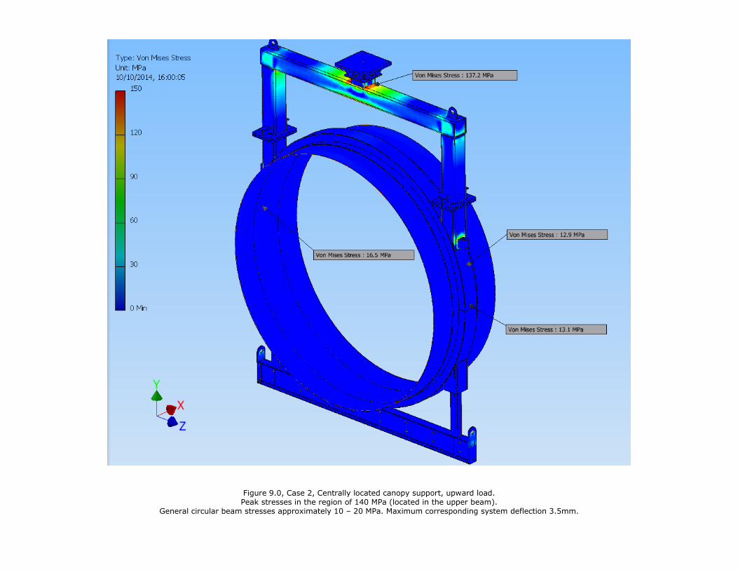
Figure 9.0, Case 2, Centrally located canopy support, upward load. Peak stresses in the region of 140 MPa (located in the upper beam).
General circular beam stresses approximately 10 – 20 MPa. Maximum corresponding system deflection 3.5mm.
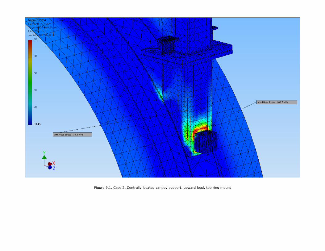
Figure 9.1, Case 2, Centrally located canopy support, upward load, top ring mount
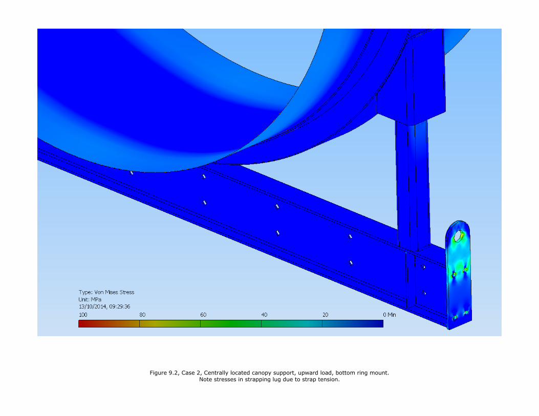
Figure 9.2, Case 2, Centrally located canopy support, upward load, bottom ring mount. Note stresses in strapping lug due to strap tension.
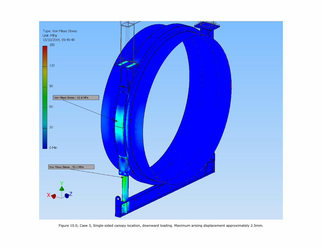
Figure 10.0, Case 3, Single-sided canopy location, downward loading. Maximum arising displacement approximately 2.5mm.
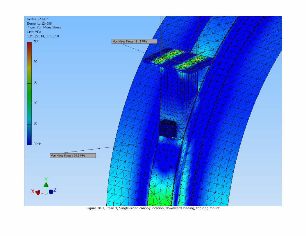
Figure 10.1, Case 3, Single-sided canopy location, downward loading, top ring mount
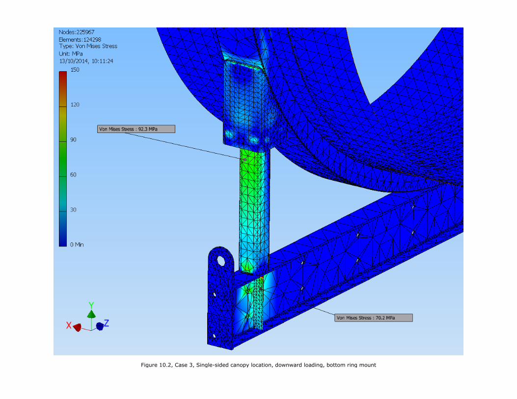
Figure 10.2, Case 3, Single-sided canopy location, downward loading, bottom ring mount
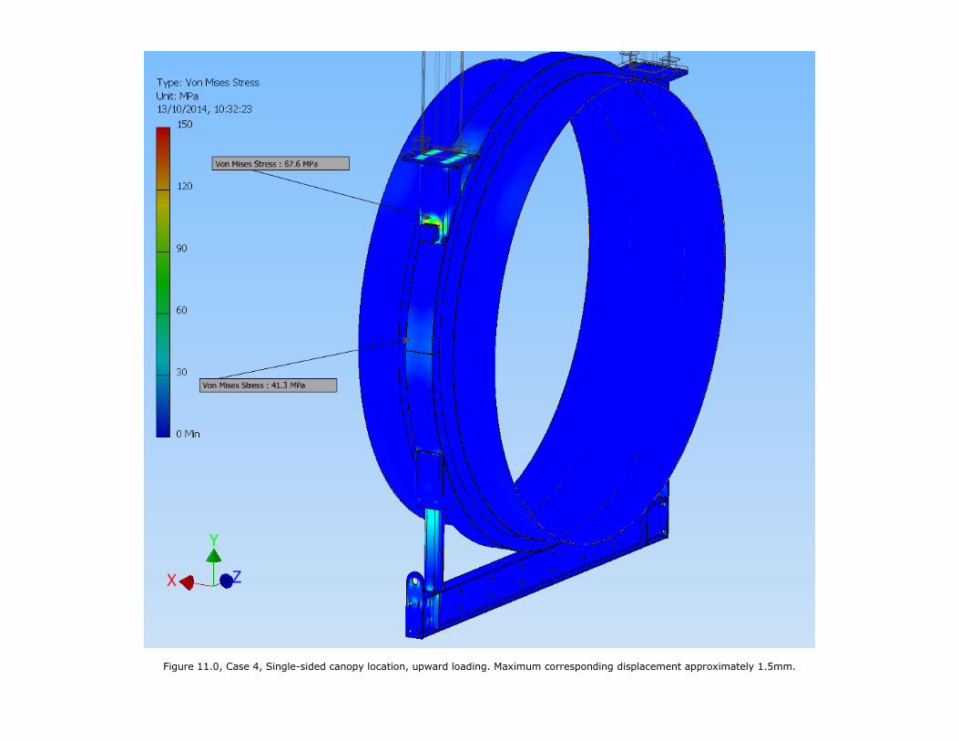
Figure 11.0, Case 4, Single-sided canopy location, upward loading. Maximum corresponding displacement approximately 1.5mm.
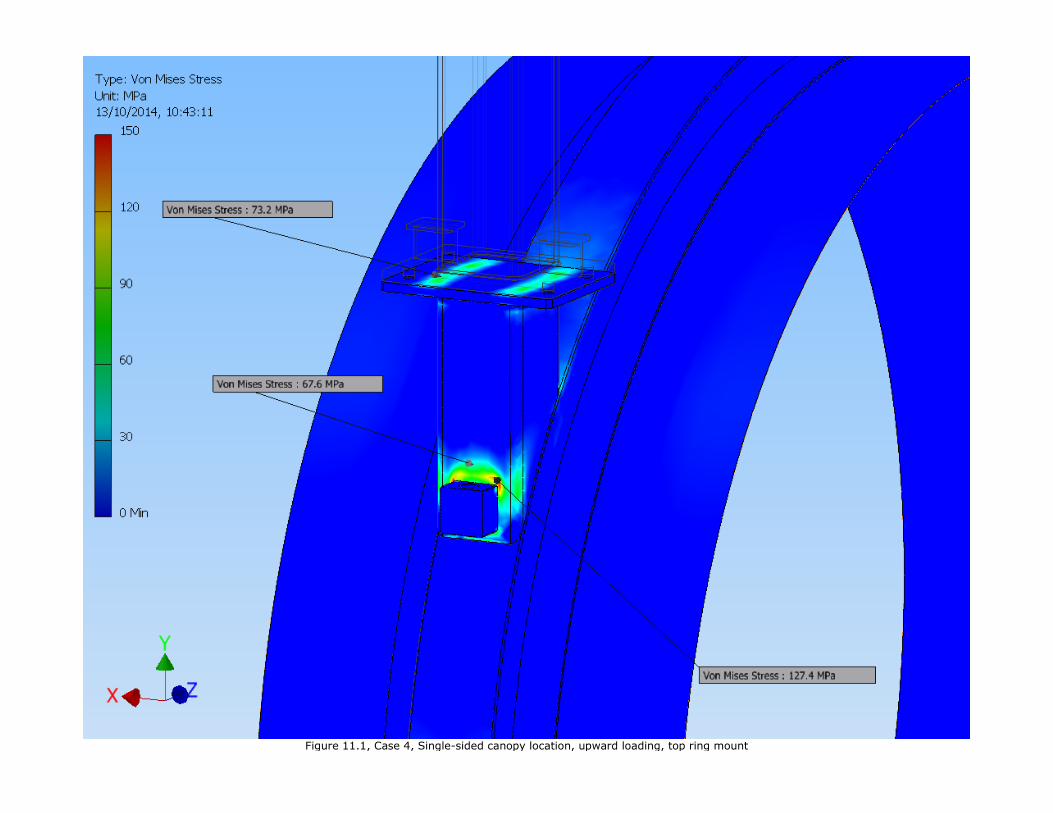
Figure 11.1, Case 4, Single-sided canopy location, upward loading, top ring mount
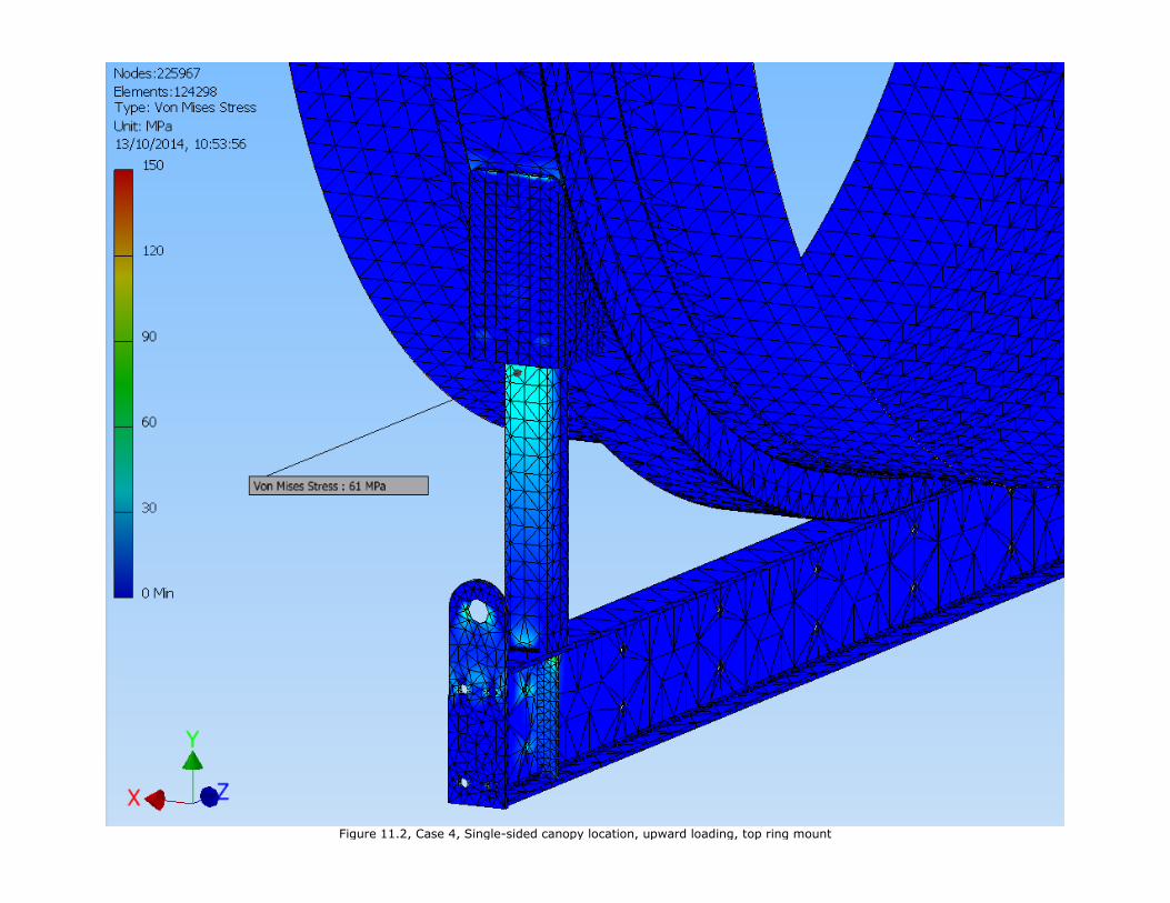
Figure 11.2, Case 4, Single-sided canopy location, upward loading, top ring mount
Benefits
To be of real interest to any potential client there must be visible and tangible benefits for
installing PetroFast modular forecourt system over the conventional systems. It is our belief that
as yet untried layouts there are major advantages and on layouts already installed in the field, we
have firm figures showing substantial savings in cost and installation periods.
Just to summarise some of the advantages.
• Maximum amount of shop fabrication and fit out – guarantying integrity of completed
system.
• Reduction in site installation time, in many cases by over 50%.
• Less complex site work means less specialists required on site.
• Cost will be saved over conventional system – in many cases substantially.
• Reduced customer migration.
• Smaller excavation needed.
• Maximise on site Health & Safety.
This document and the intellectual property contained herein remains the exclusive property of