Page 1
Proceedings of COBEM 2009 20th International Congress of Mechanical Engineering Copyright © 2009 by ABCM November 15-20, 2009, Gramado, RS, Brazil
DEVICE FOR MEASURING THE PAINTING THICKNESS AND
CIRCUNFERENCIAL DEFORMATION ON 14” PIPELINES
Vitor Ferreira Romano, [email protected] Federal University of Rio de Janeiro - Poli/UFRJ
Mechanical Engineering Department – Robotics Laboratory
Cidade Universitária – CT, Bloco G-204
CEP 21945-970 Rio de Janeiro - RJ - Brazil
Cesar Gomes Ferreira, [email protected] Digital Dinâmica Automação Ltda.
Luiz Eduardo da Silva Demenicis, [email protected] Patriot Mechanical Handling Ltd.
West Yorkshire BD17 7DW, UK
Ney Robinson Salvi dos Reis, [email protected] Petrobras/CENPES/PDP/Underwater Technology Dept.
Abstract. This article presents the mechanical design aspects of a measuring device prototype (Tinta-P) designed to
evaluate the internal operational condition on a 14” diameter pipeline for oil & derivates transportation. The scenario
of application is a 28 km length and 40 years old pipeline located in the State of Bahia, from Madre Deus marine
terminal to the Petrochemical Complex of Camaçari. The pipeline operator, Petrobras, made a contract with a company
to provide an extended life procedure against coating and corrosion, using a technology based on internal deposition
of a chemical inhibitor along the pipe. The Tinta-P prototype was developed to verify the right distribution of internal
painting in a given section of the pipeline and its circumference deformation. Tinta-P prototype has radial and
angular positioning control (R – θ directions), waterproof facilities (two meters H2O) and auto-compensation
mechanisms. The design phases of the three constructed prototypes are the main topics related to this paper. Keywords: mechatronic design, measuring device, pipeline, robotics.
1. INTRODUCTION
1.1. Operational site
Madre Deus marine terminal (Temadre) is located in the State of Bahia and since 1957 is controlled by Petrobras
(SICM, 2007). In Temadre arrives at about 40 ships per month, mainly from offshore oil drilling platforms in the
Sergipe-Alagoas Basin. Its installed facilities operate nearly 1,000,000 m3 of crude oil and derivates per month. Most
part of these products is transported by pipelines to Mataripe refinery (RLAM) and to the Petrochemical Complex of
Camaçari. Both pipelines are under the soil and in many regions the nearby area is populated. This paper deals with the
development of prototypes conceived to make internal inspections on the 28 km length pipeline from Temadre to
Camaçari.
1.2. Pipeline maintenance
Inspection of the inside surface of the pipe is necessary to verify the existence of anomalies like corrosion and
crack. Other important information regards pipe structural deformations such as bending and ovality as the result of
external forces caused by soil motion or increase of pressure due to human constructions.
Pipeline cleaning is a usual procedure to increase the capacity of product transportation, since organic deposits as
paraffin in crude oil and inner surface irregularities due to corrosion inside the pipe can cause turbulence and
consequently increase friction loss, reduce pipe bore and decrease capacity in the product flow.
2. INTERNAL INSPECTION TOOLS
2.1. Pigs
Pig is a cylinder-shaped electromechanical device designed for cleaning or inspection of the internal wall of a pipe
with non destructive testing techniques (Baldez1 et all, 2001). The term pig is associated to a device that travels with
the propelling force of the fluid being pumped (liquid) or compressed (gas) through the pipeline. Rubber seals on the
pig make it act like a piston in the pipeline. Instrumented Pig uses sensors, electronics, and recording or output
ABCM Symposium Series in Mechatronics - Vol. 4 - pp.784-792Copyright © 2010 by ABCM
Page 2
Proceedings of COBEM 2009 20th International Congress of Mechanical Engineering Copyright © 2009 by ABCM November 15-20, 2009, Gramado, RS, Brazil
functions integral to the system. While traveling the onboard data acquisition system records the defect data, sensed by
the sensors touching the internal surface of pipe wall. These data usually corresponds to defects sizing and location
along the inspected pipe (Baldez1 et all, 2001).
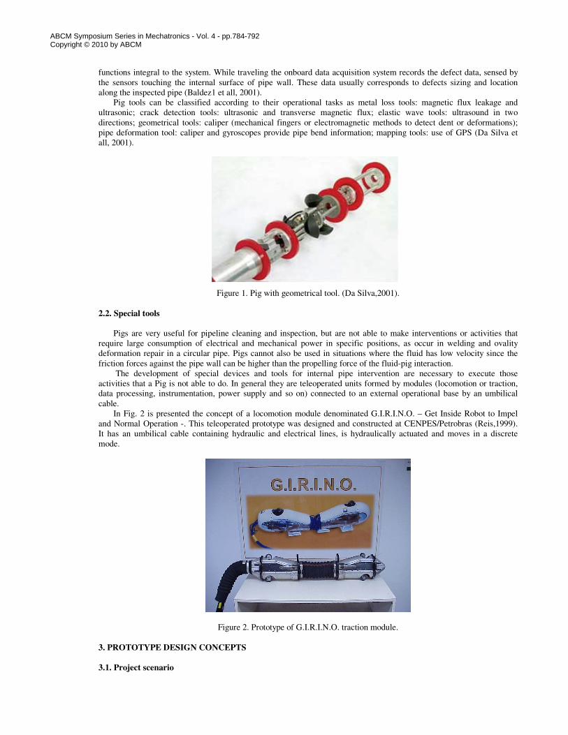
Pig tools can be classified according to their operational tasks as metal loss tools: magnetic flux leakage and
ultrasonic; crack detection tools: ultrasonic and transverse magnetic flux; elastic wave tools: ultrasound in two
directions; geometrical tools: caliper (mechanical fingers or electromagnetic methods to detect dent or deformations);
pipe deformation tool: caliper and gyroscopes provide pipe bend information; mapping tools: use of GPS (Da Silva et
all, 2001).
Figure 1. Pig with geometrical tool. (Da Silva,2001).
2.2. Special tools
Pigs are very useful for pipeline cleaning and inspection, but are not able to make interventions or activities that
require large consumption of electrical and mechanical power in specific positions, as occur in welding and ovality
deformation repair in a circular pipe. Pigs cannot also be used in situations where the fluid has low velocity since the
friction forces against the pipe wall can be higher than the propelling force of the fluid-pig interaction.
The development of special devices and tools for internal pipe intervention are necessary to execute those
activities that a Pig is not able to do. In general they are teleoperated units formed by modules (locomotion or traction,
data processing, instrumentation, power supply and so on) connected to an external operational base by an umbilical
cable.
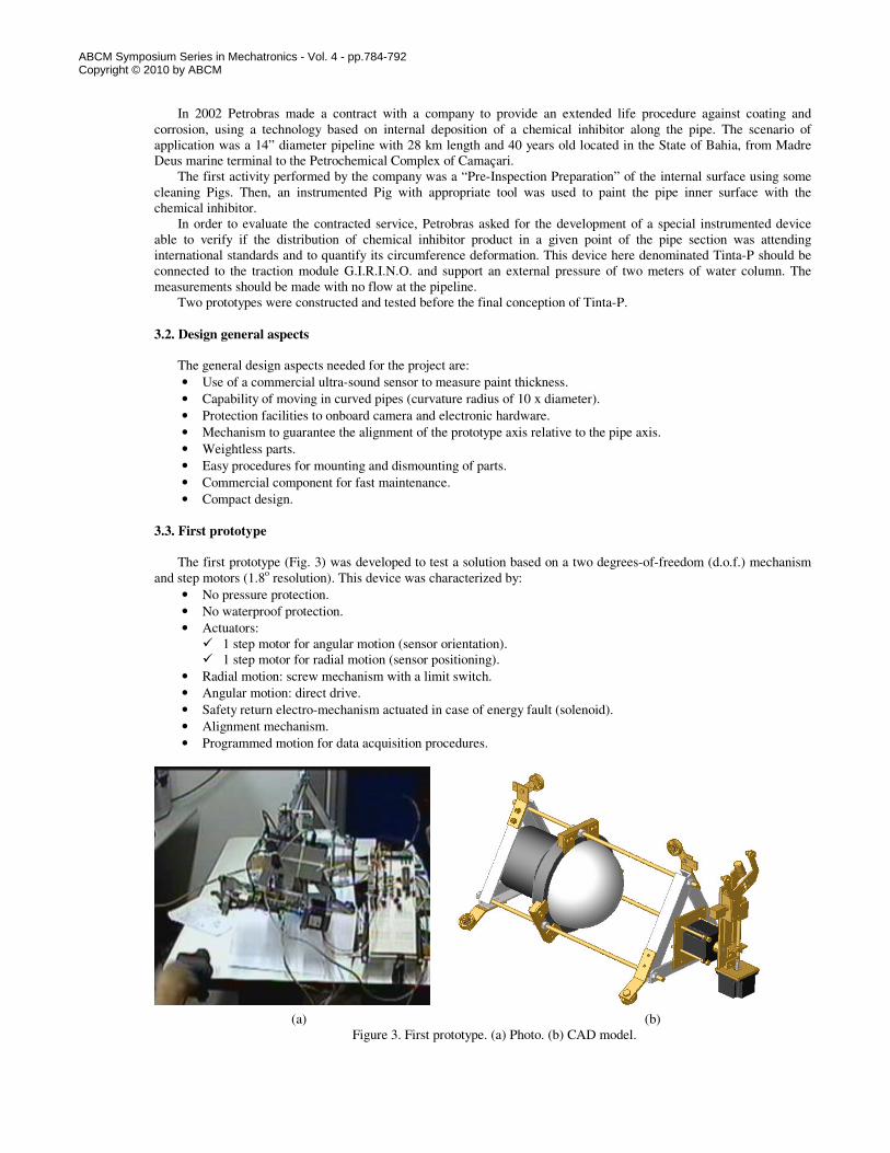
In Fig. 2 is presented the concept of a locomotion module denominated G.I.R.I.N.O. – Get Inside Robot to Impel
and Normal Operation -. This teleoperated prototype was designed and constructed at CENPES/Petrobras (Reis,1999).
It has an umbilical cable containing hydraulic and electrical lines, is hydraulically actuated and moves in a discrete
mode.
Figure 2. Prototype of G.I.R.I.N.O. traction module.
3. PROTOTYPE DESIGN CONCEPTS
3.1. Project scenario
ABCM Symposium Series in Mechatronics - Vol. 4 - pp.784-792Copyright © 2010 by ABCM
Page 3
Proceedings of COBEM 2009 20th International Congress of Mechanical Engineering Copyright © 2009 by ABCM November 15-20, 2009, Gramado, RS, Brazil
In 2002 Petrobras made a contract with a company to provide an extended life procedure against coating and
corrosion, using a technology based on internal deposition of a chemical inhibitor along the pipe. The scenario of
application was a 14” diameter pipeline with 28 km length and 40 years old located in the State of Bahia, from Madre
Deus marine terminal to the Petrochemical Complex of Camaçari.
The first activity performed by the company was a “Pre-Inspection Preparation” of the internal surface using some
cleaning Pigs. Then, an instrumented Pig with appropriate tool was used to paint the pipe inner surface with the
chemical inhibitor.
In order to evaluate the contracted service, Petrobras asked for the development of a special instrumented device
able to verify if the distribution of chemical inhibitor product in a given point of the pipe section was attending
international standards and to quantify its circumference deformation. This device here denominated Tinta-P should be
connected to the traction module G.I.R.I.N.O. and support an external pressure of two meters of water column. The
measurements should be made with no flow at the pipeline.
Two prototypes were constructed and tested before the final conception of Tinta-P.
3.2. Design general aspects
The general design aspects needed for the project are:
• Use of a commercial ultra-sound sensor to measure paint thickness.
• Capability of moving in curved pipes (curvature radius of 10 x diameter).
• Protection facilities to onboard camera and electronic hardware.
• Mechanism to guarantee the alignment of the prototype axis relative to the pipe axis.
• Weightless parts.
• Easy procedures for mounting and dismounting of parts.
• Commercial component for fast maintenance.
• Compact design.
3.3. First prototype
The first prototype (Fig. 3) was developed to test a solution based on a two degrees-of-freedom (d.o.f.) mechanism
and step motors (1.8o resolution). This device was characterized by:
• No pressure protection.
• No waterproof protection.
• Actuators:
� 1 step motor for angular motion (sensor orientation).
� 1 step motor for radial motion (sensor positioning).
• Radial motion: screw mechanism with a limit switch.
• Angular motion: direct drive.
• Safety return electro-mechanism actuated in case of energy fault (solenoid).
• Alignment mechanism.
• Programmed motion for data acquisition procedures.
(a) (b)
Figure 3. First prototype. (a) Photo. (b) CAD model.
ABCM Symposium Series in Mechatronics - Vol. 4 - pp.784-792Copyright © 2010 by ABCM
Page 4
Proceedings of COBEM 2009 20th International Congress of Mechanical Engineering Copyright © 2009 by ABCM November 15-20, 2009, Gramado, RS, Brazil
Figure 4. First prototype: mechanism main parts.
The first prototype mechanism worked properly but undesired vibrations occurred in the radial motion. Another
critical part was the small amplitude of the alignment mechanism, reducing the system capability to move in curved
pipes.
3.4. Second prototype
The main improvements made on the second prototype (Fig. 5) are related to the modified alignment system,
ensuring more amplitude and rigidity to the system, and the adjustments on the motion mechanism to reduce vibration.
Figure 5. Second prototype.
The performance of this prototype was acceptable for the measuring of the specified parameters. After some tests
the design team started the development of the final prototype.
4. TINTA-P PROTOTYPE
This final version prototype is characterized by the following improvements (Figs. 6 and 7):
• Radial and angular positioning control (R – θ directions).
elevator unit
motor 1
motor 2
ultra-sound sensor
solenoid
alignment mechanism
ABCM Symposium Series in Mechatronics - Vol. 4 - pp.784-792Copyright © 2010 by ABCM
Page 5
Proceedings of COBEM 2009 20th International Congress of Mechanical Engineering Copyright © 2009 by ABCM November 15-20, 2009, Gramado, RS, Brazil
• Teleoperated or robotic operation modes.
• Waterproof (2 meters H2O) and explosion-proof container unit.
• Auto-compensated alignment system.
• Radial motion unit: pneumatic actuator and 2 d.o.f. mechanism.
• Angular motion: DC motor and planetary gear reduction.
• Pendulum sensor system to keep horizontal reference.
Figure 6. Tinta-P prototype and pipeline CAD model.
Figure 7. Details of Tinta-P components.
4.1. Structural unit
The structural unit provides the necessary rigidity, alignment and protection to all system units. It has stainless steel
components and is formed by two circular shape flanges rigidly interconnected by three structural bars in pretension
with screws.
The structure is also responsible for container unit protection against external forces/moments due to pipeline
interaction.
4.2. Container unit
alignment unit
(back side)
central flange
motor
compressor
pendulum
back side
flange
frontal flange
Motion direction
structural bar
umbilical
alignment unit
(front side)
container unit
14” pipeline
alignment unit
radial motion
mechanism
ABCM Symposium Series in Mechatronics - Vol. 4 - pp.784-792Copyright © 2010 by ABCM
Page 6
Proceedings of COBEM 2009 20th International Congress of Mechanical Engineering Copyright © 2009 by ABCM November 15-20, 2009, Gramado, RS, Brazil
The container unit is located inside the structure and has cylinder components made in PVC. Its main functions are:
isolation from external pressure and humidity (waterproof for 2 meters H2O) of the onboard components, such as
electronics – motor, encoders, data acquisition and control circuits, communication circuit - and pneumatic system –
compressor, directional valves, air pressure reservoir -, and explosion-proof capability
The onboard components can be easily accessed due to container unit modular concept, as presented in Fig. 8.
Figure 8. Details of the Tinta-P container unit and onboard components.
4.3. Sensor unit
Tinta-P was designed to measure in a given transverse section of the pipeline inner surface, the coordinates of
selected points referenced to pipeline symmetry axis and their associated chemical inhibitor thickness. The database of
sampled points represents the section mapping situation in terms of geometrical parameters: radial deformations due to
external pressure from soil interaction and distribution of the internal painting.
A commercial ultra-sound calibrated transducer was used to evaluate the chemical inhibitor thickness. The sensor is
located in a linear platform that moves in connection with a piston rod. When the piston rod moves upward and touches
the pipe inner surface, the sensor achieves its proper position, orientation and contact force due to adjustment of a
spring located in the extended extremity of a two d.o.f. arm.
Figure 9. Details of the Tinta-P container unit and onboard components.
4.4. Alignment Unit
thickness transducer
spring piston rod
arm
encoder axis
container unit
(main body)
ABCM Symposium Series in Mechatronics - Vol. 4 - pp.784-792Copyright © 2010 by ABCM
Page 7
Proceedings of COBEM 2009 20th International Congress of Mechanical Engineering Copyright © 2009 by ABCM November 15-20, 2009, Gramado, RS, Brazil
The auto-compensated alignment system is formed by back side and front side units (Fig. 7). Each one contains a
tripod mechanism with wheels actuated by a rigid spring.
This system tends to keep the geometrical axis of the Tinta-P concentrically to the theoretical symmetry axis of
the pipeline, in the vicinity of the region of analysis.
5. Motion Especification
In order to sample representative points located in the internal circumference of the pipeline wall, Tinta-P is able to
move in the radial and angular directions.
5.1. Radial motion
The radial motion is obtained with the displacement of a piston rod associated to a pneumatic cylinder. This
motion is necessary to move the ultra-sound transducer nearby the measurement point.
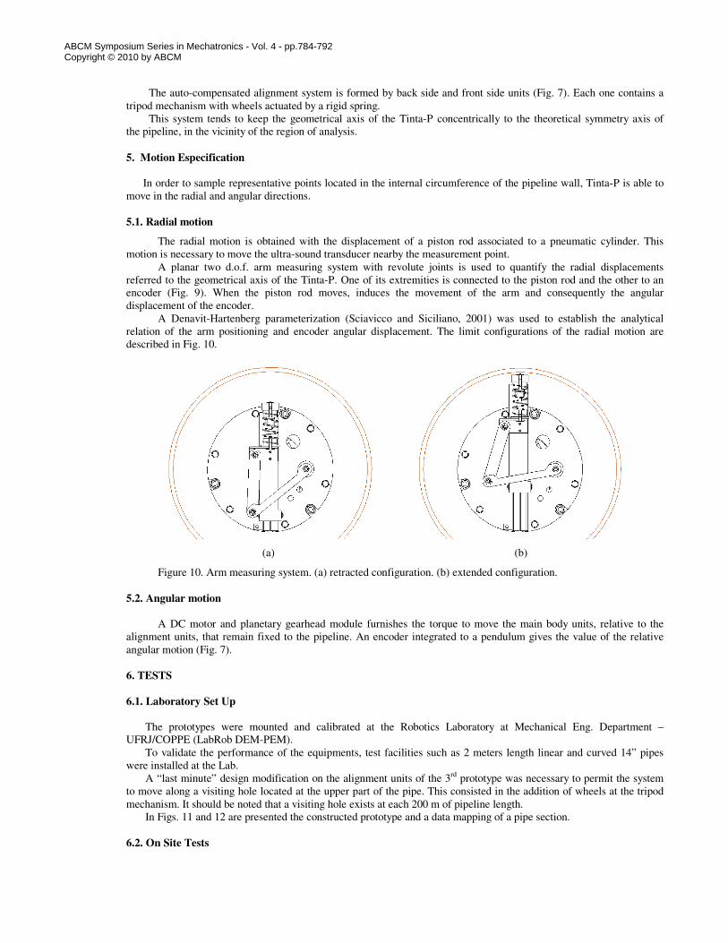
A planar two d.o.f. arm measuring system with revolute joints is used to quantify the radial displacements
referred to the geometrical axis of the Tinta-P. One of its extremities is connected to the piston rod and the other to an
encoder (Fig. 9). When the piston rod moves, induces the movement of the arm and consequently the angular
displacement of the encoder.
A Denavit-Hartenberg parameterization (Sciavicco and Siciliano, 2001) was used to establish the analytical
relation of the arm positioning and encoder angular displacement. The limit configurations of the radial motion are
described in Fig. 10.
(a) (b)
Figure 10. Arm measuring system. (a) retracted configuration. (b) extended configuration.
5.2. Angular motion
A DC motor and planetary gearhead module furnishes the torque to move the main body units, relative to the
alignment units, that remain fixed to the pipeline. An encoder integrated to a pendulum gives the value of the relative
angular motion (Fig. 7).
6. TESTS
6.1. Laboratory Set Up
The prototypes were mounted and calibrated at the Robotics Laboratory at Mechanical Eng. Department –
UFRJ/COPPE (LabRob DEM-PEM).
To validate the performance of the equipments, test facilities such as 2 meters length linear and curved 14” pipes
were installed at the Lab.
A “last minute” design modification on the alignment units of the 3rd
prototype was necessary to permit the system
to move along a visiting hole located at the upper part of the pipe. This consisted in the addition of wheels at the tripod
mechanism. It should be noted that a visiting hole exists at each 200 m of pipeline length.
In Figs. 11 and 12 are presented the constructed prototype and a data mapping of a pipe section.
6.2. On Site Tests
ABCM Symposium Series in Mechatronics - Vol. 4 - pp.784-792Copyright © 2010 by ABCM
Page 8
Proceedings of COBEM 2009 20th International Congress of Mechanical Engineering Copyright © 2009 by ABCM November 15-20, 2009, Gramado, RS, Brazil
While the 3rd
prototype was under tests at the LabRob DEM-PEM, the 2nd
prototype was sent to Bahia, in order to
measure a pipeline sample submitted to the internal painting.
The 2nd
prototype measured data proved that the distribution of chemical inhibitor product in a tested pipe section
was not according to Petrobras standards.
Based on these results Petrobras was able to punish the company and redefine the service.
(a) (b)
Figure 11. (a) Prototype at the Lab. (b) Testes in a curved 14” pipe.
Figure 12. Mapping of a pipe section.
7. CONCLUSIONS
The mechanical characteristics of the second and third prototypes were able to measure the internal distribution of
chemical inhibitor product in a 14” pipeline section and its circumference deformation.
Although the concept of the 3rd
prototype was more sophisticated then the 2nd
one, the on site measuring tests with
the 2nd
prototype was enough to evaluate the pipeline conditions, according to Petrobras standards.
The successful performance of the equipment helped Petrobras to redefine the service and new conditions were
established.
For future developments the authors suggest a new concept based on hydraulic actuators, so that a high pressure
could be applied to the equipment and measurements be made with the presence of fluid flow at the pipeline.
8. ACKNOLEDGEMENTS
The authors thank prof. Liu Hsu for his participation as Project Coordinator.
This project was mainly financed with FINEP/CT-Petro 1 funds. Partial funds were also obtained with CNPq.
9. REFERENCES
ABCM Symposium Series in Mechatronics - Vol. 4 - pp.784-792Copyright © 2010 by ABCM
Page 9
Proceedings of COBEM 2009 20th International Congress of Mechanical Engineering Copyright © 2009 by ABCM November 15-20, 2009, Gramado, RS, Brazil
Beitz, W. and Küttner K.-H., Editors, 1994, “Dubbel Handbook of Mechanical Engineering”, Springer-Verlag, U.K.
Dorf, R.C., Bishop. R. H., 2001, “ Modern Control Systems” (in Portuguese), Ed. LTC, pp. 93-127.
Reis, N.R.S., “Get Inside Robot to Impel and Normal Operation – G.I.R.I.N.O.”, 1999
http://www.bahiainvest.com.br/ing/index.asp, BahiaInvest Portal's, State Secretariat of Industry, Commerce, and
Mining (SICM), 2007.
Da Silva, J. A. Pereira and Pinho, A. F. “Ferramenta para Inspeção Geométrica de Dutos de 3 pol.” (in portuguese), 3rd
Seminar on Pipeline, CD version, Brazilian Petroleum and Gas Institute – IBP, Rio de Janeiro, Brazil, November 2001.
Baldez1 M., Pereira, J.A., Janvrot, I.V., Camerini C.S., “Inspeções com Pigs Geométricos: Principais Resultados de
Campo” (in portuguese), 3rd Seminar on Pipeline, CD version, Brazilian Petroleum and Gas Institute – IBP, Rio de
Janeiro, Brazil, November 2001
Sciavicco, L. and Siciliano, B., Modeling and Control of Robot Manipulators. UK, Springer-Verlag, 2001.
10. RESPONSIBILITY NOTICE
The authors are the only responsible for the printed material included in this paper.
ABCM Symposium Series in Mechatronics - Vol. 4 - pp.784-792Copyright © 2010 by ABCM