RULES FOR CLASSIFICATION OF DET NORSKE VERITAS Veritasveien 1, NO-1322 Høvik, Norway Tel.: +47 67 57 99 00 Fax: +47 67 57 99 11 HIGH SPEED, LIGHT CRAFT AND NAVAL SURFACE CRAFT MACHINERY AND SYSTEMS EQUIPMENT AND OPERATION PART 4 CHAPTER 6 PIPING SYSTEMS JANUARY 2011 CONTENTS PAGE Sec. 1 General Requirements .......................................................................................................... 5 Sec. 2 Materials .............................................................................................................................. 7 Sec. 3 Design Principles ................................................................................................................. 8 Sec. 4 Craft Piping Systems............................................................................................................ 9 Sec. 5 Machinery Piping Systems and Ventilation....................................................................... 12 Sec. 6 Pipes, Pumps, Valves, Flexible Hoses and Detachable Pipe Connections ........................ 17 Sec. 7 Manufacture, Workmanship, Inspection and Testing ........................................................ 22
Transcript
RULES FORCLASSIFICATION OF
HIGH SPEED, LIGHT CRAFT ANDNAVAL SURFACE CRAFT
MACHINERY AND SYSTEMSEQUIPMENT AND OPERATION
PART 4 CHAPTER 6
PIPING SYSTEMSJANUARY 2011
CONTENTS PAGE
Sec. 1 General Requirements.......................................................................................................... 5Sec. 2 Materials .............................................................................................................................. 7Sec. 3 Design Principles ................................................................................................................. 8Sec. 4 Craft Piping Systems............................................................................................................ 9Sec. 5 Machinery Piping Systems and Ventilation....................................................................... 12Sec. 6 Pipes, Pumps, Valves, Flexible Hoses and Detachable Pipe Connections ........................ 17Sec. 7 Manufacture, Workmanship, Inspection and Testing ........................................................ 22
DET NORSKE VERITASVeritasveien 1, NO-1322 Høvik, Norway Tel.: +47 67 57 99 00 Fax: +47 67 57 99 11
CHANGES IN THE RULES
GeneralAs of October 2010 all DNV service documents are primarily published electronically.In order to ensure a practical transition from the “print” scheme to the “electronic” scheme, all rule chapters havingincorporated amendments and corrections more recent than the date of the latest printed issue, have been given the dateJanuary 2011. An overview of DNV service documents, their update status and historical “amendments and corrections” may be foundthrough http://www.dnv.com/resources/rules_standards/.
Main changesSince the previous edition (January 2002) this chapter has been amended, most recently in July 2008. All changespreviously found in Pt.0 Ch.1 Sec.3 have been incorporated and a new date (January 2011) has been given as explainedunder “General”.In addition, the layout has been changed to one column in order to improve electronic readability.
Any comments may be sent by e-mail to [email protected] subscription orders or information about subscription terms, please use [email protected] Typesetting (Adobe Frame Maker) by Det Norske Veritas
If any person suffers loss or damage which is proved to have been caused by any negligent act or omission of Det Norske Veritas, then Det Norske Veritas shall pay compensation tosuch person for his proved direct loss or damage. However, the compensation shall not exceed an amount equal to ten times the fee charged for the service in question, provided thatthe maximum compensation shall never exceed USD 2 million.In this provision "Det Norske Veritas" shall mean the Foundation Det Norske Veritas as well as all its subsidiaries, directors, officers, employees, agents and any other acting on behalfof Det Norske Veritas.
Rules for High Speed, Light Craft and Naval Surface Craft, January 2011 Pt.4 Ch.6 Contents – Page 3
CONTENTS
Sec. 1 General Requirements ....................................................................................................................... 5
A. Classification.................................................................................................................................................................. 5A 100 Application............................................................................................................................................................ 5
B. Definitions ...................................................................................................................................................................... 5B 100 Terms .................................................................................................................................................................... 5
C. Documentation .............................................................................................................................................................. 5C 100 Plans and particulars ............................................................................................................................................. 5
D. Signboards ..................................................................................................................................................................... 6D 100 General.................................................................................................................................................................. 6
Sec. 2 Materials ............................................................................................................................................. 7
Sec. 3 Design Principles ................................................................................................................................ 8
A. Arrangement.................................................................................................................................................................. 8A 100 Piping systems ...................................................................................................................................................... 8A 200 Operation of valves ............................................................................................................................................... 8
Sec. 4 Craft Piping Systems.......................................................................................................................... 9
A. Bilge Pumping, Drainage, Air, Sounding and Filling Pipes ...................................................................................... 9A 100 Bilge pumping and drainage systems ................................................................................................................... 9A 200 Air, sounding and filling pipes ........................................................................................................................... 10A 300 Scuppers and discharges ..................................................................................................................................... 11A 400 Fittings on sides and bottom ............................................................................................................................... 11
Sec. 5 Machinery Piping Systems and Ventilation................................................................................... 12
A. General ......................................................................................................................................................................... 12A 100 Tank arrangement for fuel oil or other flammable fluids ................................................................................... 12A 200 Piping conveying fuel or other flammable fluids ............................................................................................... 12A 300 Lubricating oil arrangements .............................................................................................................................. 13A 400 Arrangements for heated fuel oil tanks and equipment for fuel oil treatment ................................................... 13A 500 Arrangement for fuel oil with flashpoint below 43°C ........................................................................................ 13
B. Other Systems.............................................................................................................................................................. 14B 100 Ballast systems.................................................................................................................................................... 14B 200 Cooling systems .................................................................................................................................................. 14B 300 Starting systems .................................................................................................................................................. 14B 400 Exhaust systems .................................................................................................................................................. 14B 500 Engine air intake systems ................................................................................................................................... 15B 600 Machinery space ventilation ............................................................................................................................... 15B 700 Pneumatic equipment.......................................................................................................................................... 16
Sec. 6 Pipes, Pumps, Valves, Flexible Hoses and Detachable Pipe Connections................................... 17
A. Pipes.............................................................................................................................................................................. 17A 100 General................................................................................................................................................................ 17A 200 Minimum wall thicknesses of metallic pipes...................................................................................................... 17A 300 Plastic pipes ........................................................................................................................................................ 17
Sec. 7 Manufacture, Workmanship, Inspection and Testing.................................................................. 22
A. Joining of Plastic Pipes ............................................................................................................................................... 22A 100 General................................................................................................................................................................ 22
B. Welding and Brazing .................................................................................................................................................. 22B 100 General................................................................................................................................................................ 22
C. Hydrostatic Tests of Piping ........................................................................................................................................ 22C 100 Hydrostatic testing after assembly on board....................................................................................................... 22
D. Functional Testing....................................................................................................................................................... 22D 100 General................................................................................................................................................................ 22
E. Non-Destructive Testing ............................................................................................................................................. 23E 100 General................................................................................................................................................................ 23
DET NORSKE VERITAS
Rules for High Speed, Light Craft and Naval Surface Craft, January 2011 Pt.4 Ch.6 Sec.1 – Page 5
SECTION 1 GENERAL REQUIREMENTS
A. ClassificationA 100 Application101 The rules in this chapter apply to piping for the assignment of class notation LC and HSLC.102 Compliance with the rules is required for installations and equipment necessary for performing the mainfunctions given in Pt.1 Ch.1 Sec.2.103 The rules give system requirements and prescribe minimum requirements for materials, design,manufacture, inspection and testing.104 Text quoted from the International Code of Safety for High-Speed Craft (2000 HSC Code) is printed initalics.105 For the application of these rules, wherever the term Administration is quoted, this is to be read as theSociety.
B. DefinitionsB 100 Terms101 Piping is defined to include the following components:
— pipes— flanges with gaskets and bolts and other pipe connections— expansion elements— valves, including hydraulic and pneumatic actuators, and fittings— hangers and supports— flexible hoses— pump housings.
102 A piping system is defined to include piping, as well as components in direct connection to the pipingsuch as pumps, heat exchangers, evaporators, independent tanks, etc. with the exception of main componentssuch as steam and gas turbines, diesel engines, reduction gears and boilers.For components which are subject to internal pressure and are not included in the piping, the designrequirements in Ch.7 apply.
C. DocumentationC 100 Plans and particulars101 Plans showing machinery arrangement are to be submitted for information.These are to show layout of machinery components such as engines, fans, heat exchangers, generators,switchboards, pumps, purifiers, filters etc. but excluding pipes, valves and accessories.102 Diagrammatic plans for the following systems and arrangements are to be submitted in triplicate forapproval:
— bilge pumping and drainage systems— ballast system— air, overflow, sounding and filling pipes— scuppers and discharges— fittings on sides and bottom— tank arrangement for fuel and other flammable fluids— fuel oil systems and piping conveying fuel or other flammable fluids— lubricating oil systems— cooling water systems— starting systems— exhaust piping— machinery space ventilation— arrangement of hydraulic and pneumatic systems for:
DET NORSKE VERITAS
Rules for High Speed, Light Craft and Naval Surface Craft, January 2011 Pt.4 Ch.6 Sec.1 – Page 6
— windlasses— starting of engines— remote control of valves and watertight doors.
103 The diagrammatic plans are to include the following particulars:
— outside diameter and wall thickness of pipes— materials to be used in pipes, valve bodies and fittings— pump type and capacity— type of flexible hoses and expansion elements— maximum working pressure if exceeding 7 bar— maximum temperature if exceeding 60°C.
104 Analyses of reliability and availability are to be submitted upon request when considered necessary bythe Society.These analyses are to include information on possible numerical background material.105 Documentation for the control and monitoring system for valves and pumps for systems listed in 102shall be submitted for approval, if arranged. For requirements for documentation types, see Ch.9.
D. SignboardsD 100 General101 Signboards provide information or certain conditions to be complied with for the safe handling ofmachinery components and systems.Some signboards are required by the rules, others may be required by the Society in each particular case.In Sec.1 of each chapter a summary of the signboards required by the rules in that chapter is introduced.
DET NORSKE VERITAS
Rules for High Speed, Light Craft and Naval Surface Craft, January 2011 Pt.4 Ch.6 Sec.2 – Page 7
SECTION 2 MATERIALS
A. Piping SystemsA 100 General101 The materials to be used in piping systems are to be suitable for the medium and service for which thesystem is intended. Unless specifically mentioned all metallic materials with melting point above 900°C maybe used.
Guidance note:Stainless steel is generally not considered suitable for use in seawater systems.
---e-n-d---of---G-u-i-d-a-n-c-e---n-o-t-e---
A 200 Copper and copper alloys201 Copper and copper alloys are in general not to be used for media having temperature above the followinglimits:
— copper and aluminium brass: 200°C — copper nickel: 300°C.
Special bronze suitable for high temperature service may be used for media having temperature up to 260°C.202 Pipes for starting air are not to be of copper or copper alloys when the outer diameter exceeds 44.5 mm.
A 300 Non-metallic materials301 Pipes made from non-metallic materials may be used in piping systems with the following exceptions:
— systems conveying flammable fluids— systems with design pressure above 16 bar— fire extinguishing systems.
302 Pipes for non-essential services may be of a recognized standard for domestic water services.
A 400 Aluminium401 Pipes made from aluminium may be used for services mentioned in 301. In addition, air, sounding and filling pipes for aluminium tanks may be made from the same material, providedthese pipes are located outside fire hazard areas.
DET NORSKE VERITAS
Rules for High Speed, Light Craft and Naval Surface Craft, January 2011 Pt.4 Ch.6 Sec.3 – Page 8
SECTION 3 DESIGN PRINCIPLES
A. ArrangementA 100 Piping systems101 Piping systems are normally to be made of rigid pipes. The use of flexible hoses of approved type suitablefor their intended use may be accepted in lieu of rigid piping upon special consideration. Pipes and fittings areto be supported in such a way that their weight is not taken by connected machinery or that heavy valves andfittings do not cause large additional stresses in adjacent pipes.102 Axial forces due to internal pressure, change in direction or cross-sectional area and movement of thecraft are to be taken into consideration when mounting the piping system.103 The support of the piping system is to be such that detrimental vibrations will not arise in the system.104 Metallic pipes are to be connected by welding or brazing in accordance with the requirements in Sec.7B or by detachable connections of approved type.105 Plastic pipes are to be connected by an approved method e.g. welding, gluing or cementing, or byapproved detachable connections.106 Installation of pipes for water or oil, behind or above electric switchboards is to be avoided as far aspossible. If this is impracticable, all detachable pipe joints and valves are to be at a safe distance from theswitchboard or well shielded from it.107 Water pipes and air and sounding pipes through freezing chambers are to be avoided.
A 200 Operation of valves201 Sea suction and discharge valves, bilge valves and valves on the fuel oil and lubricating oil tanks whichare situated higher than the double bottom tanks, are to be arranged for local mechanical manual operation. Thechange over to manual operation from possible remote control arrangement is to be simple to execute.202 For remotely controlled valves failure in power supply is not to cause:
— opening of closed valves— closing of open valves on fuel oil tanks and in cooling water system for propulsion and power generating
machinery.
203 Remotely controlled valves are to be provided with indications for open and closed valve positions at thecontrol station.In cases where possibility of direct manual operation is required in addition to the remote control, means ofobserving the valve position at the valve location is to be provided.
DET NORSKE VERITAS
Rules for High Speed, Light Craft and Naval Surface Craft, January 2011 Pt.4 Ch.6 Sec.4 – Page 9
SECTION 4 CRAFT PIPING SYSTEMS
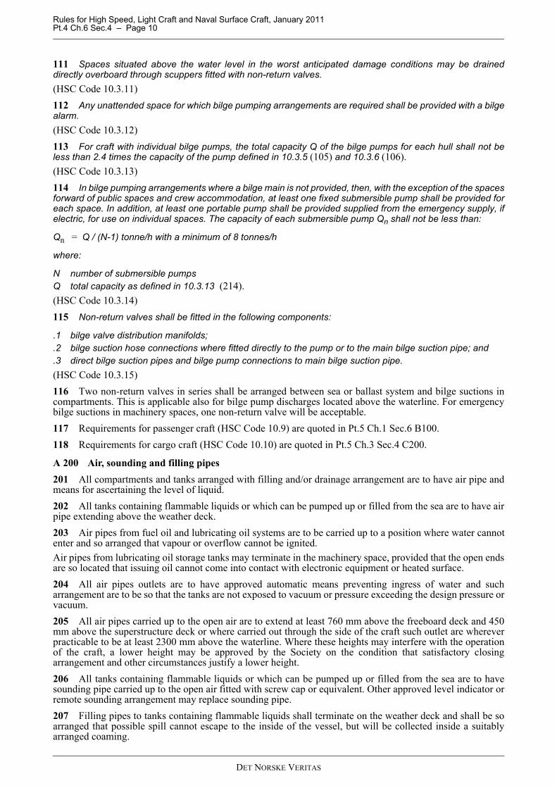
A. Bilge Pumping, Drainage, Air, Sounding and Filling PipesA 100 Bilge pumping and drainage systems101 Arrangements shall be made for draining any watertight compartment other than the compartmentsintended for permanent storage of liquid. Where, in relation to particular compartments, drainage is notconsidered necessary, drainage arrangements may be omitted, but it shall be demonstrated that the safety ofthe craft will not be impaired.(HSC Code 10.3.1)102 Bilge pumping arrangements shall be provided to allow every watertight compartment other than thoseintended for permanent storage of liquid to be drained. The capacity or position of any such compartment shallbe such that flooding thereof could not affect the safety of the craft.(HSC Code 10.3.2)103 The bilge pumping system shall be capable of operation under all possible values of list and trim afterthe craft has sustained the postulated damage in 2.6.5 to 2.6.8. The bilge pumping system shall be sodesigned as to prevent water flowing from one compartment to another. The necessary valves for controllingthe bilge suctions shall be capable of being operated from above the datum. All distribution boxes and manuallyoperated valves in connection with the bilge pumping arrangements shall be in positions which are accessibleunder ordinary circumstances. (HSC Code 10.3.3)104 The power-operated self-priming bilge pumps may be used for other duties such as fire fighting orgeneral service but not for pumping fuel or other flammable liquids.(HSC Code 10.3.4)105 Each power bilge pump shall be capable of pumping water through the required bilge pipe at a speed ofnot less than 2 m/s.(HSC Code 10.3.5)106 The diameter (d) of the bilge main shall be calculated according to the following formula, except that theactual internal diameter of the bilge main may be rounded off to the nearest size of a recognized standard:
d = 25 + 1.68 (L (B + D)) 0.5
where:
d is the internal diameter of the bilge main (mm);L is the length of the craft (m) as defined in chapter 1 (Pt.0 Ch.6);B is for monohull craft, the breadth of the craft in m as defined in chapter 1 (Pt.0 Ch.6) and, for multihull craft,
the breadth of a hull at or below the design waterline (m); andD is the moulded depth of the craft to the datum (m).(HSC Code 10.3.6)
Guidance note:Reference is given to Ch.1 Sec.1 A306 regarding the definition of the word datum.
---e-n-d---of---G-u-i-d-a-n-c-e---n-o-t-e---
107 Internal diameters of suction branches shall meet the requirements of the Administration but shall not beless than 25 mm. Suction branches shall be fitted with effective strainers.(HSC Code 10.3.7)108 An emergency bilge suction shall be provided for each machinery space containing a propulsion primemover. This suction shall be led to the largest available power pump other than a bilge pump, propulsion pumpor oil pump.(HSC Code 10.3.8)109 The spindles of the sea inlet valves shall extend well above the machinery space floor plates.(HSC Code 10.3.9)110 All bilge suction piping up to the connection to the pumps shall be independent of other piping.(HSC Code 10.3.10)
DET NORSKE VERITAS
Rules for High Speed, Light Craft and Naval Surface Craft, January 2011 Pt.4 Ch.6 Sec.4 – Page 10
111 Spaces situated above the water level in the worst anticipated damage conditions may be draineddirectly overboard through scuppers fitted with non-return valves.(HSC Code 10.3.11)112 Any unattended space for which bilge pumping arrangements are required shall be provided with a bilgealarm.(HSC Code 10.3.12)113 For craft with individual bilge pumps, the total capacity Q of the bilge pumps for each hull shall not beless than 2.4 times the capacity of the pump defined in 10.3.5 (105) and 10.3.6 (106).(HSC Code 10.3.13)114 In bilge pumping arrangements where a bilge main is not provided, then, with the exception of the spacesforward of public spaces and crew accommodation, at least one fixed submersible pump shall be provided foreach space. In addition, at least one portable pump shall be provided supplied from the emergency supply, ifelectric, for use on individual spaces. The capacity of each submersible pump Qn shall not be less than:
Qn = Q / (N-1) tonne/h with a minimum of 8 tonnes/h
where:
N number of submersible pumpsQ total capacity as defined in 10.3.13 (214).(HSC Code 10.3.14)115 Non-return valves shall be fitted in the following components:
.1 bilge valve distribution manifolds;
.2 bilge suction hose connections where fitted directly to the pump or to the main bilge suction pipe; and
.3 direct bilge suction pipes and bilge pump connections to main bilge suction pipe.(HSC Code 10.3.15)116 Two non-return valves in series shall be arranged between sea or ballast system and bilge suctions incompartments. This is applicable also for bilge pump discharges located above the waterline. For emergencybilge suctions in machinery spaces, one non-return valve will be acceptable.117 Requirements for passenger craft (HSC Code 10.9) are quoted in Pt.5 Ch.1 Sec.6 B100.118 Requirements for cargo craft (HSC Code 10.10) are quoted in Pt.5 Ch.3 Sec.4 C200.
A 200 Air, sounding and filling pipes201 All compartments and tanks arranged with filling and/or drainage arrangement are to have air pipe andmeans for ascertaining the level of liquid.202 All tanks containing flammable liquids or which can be pumped up or filled from the sea are to have airpipe extending above the weather deck.203 Air pipes from fuel oil and lubricating oil systems are to be carried up to a position where water cannotenter and so arranged that vapour or overflow cannot be ignited.Air pipes from lubricating oil storage tanks may terminate in the machinery space, provided that the open endsare so located that issuing oil cannot come into contact with electronic equipment or heated surface.204 All air pipes outlets are to have approved automatic means preventing ingress of water and sucharrangement are to be so that the tanks are not exposed to vacuum or pressure exceeding the design pressure orvacuum.205 All air pipes carried up to the open air are to extend at least 760 mm above the freeboard deck and 450mm above the superstructure deck or where carried out through the side of the craft such outlet are whereverpracticable to be at least 2300 mm above the waterline. Where these heights may interfere with the operationof the craft, a lower height may be approved by the Society on the condition that satisfactory closingarrangement and other circumstances justify a lower height.206 All tanks containing flammable liquids or which can be pumped up or filled from the sea are to havesounding pipe carried up to the open air fitted with screw cap or equivalent. Other approved level indicator orremote sounding arrangement may replace sounding pipe.207 Filling pipes to tanks containing flammable liquids shall terminate on the weather deck and shall be soarranged that possible spill cannot escape to the inside of the vessel, but will be collected inside a suitablyarranged coaming.
DET NORSKE VERITAS
Rules for High Speed, Light Craft and Naval Surface Craft, January 2011 Pt.4 Ch.6 Sec.4 – Page 11
208 All filling pipes to fuel oil and lubricating oil tanks are to have screw caps, plugs or similar arrangementpreventing water from entering such tanks.209 Overflow pipes are to have sectional area not less than 125% of the filling pipes. The same requirementapplies to air pipes on tanks not fitted with overflow pipes.
A 300 Scuppers and discharges301 A sufficient number of scuppers, arranged to provide effective drainage, is to be fitted to all decks.302 Scuppers on weather portions of decks and scuppers leading from superstructures or deckhouses notprovided with closing appliances, are usually to be led overboard.303 Scuppers led through the deck or shell are to comply with requirements to material and thickness as givenin 403.304 Scupper pipes are to be well stayed to prevent any vibrations. However, sufficient possibility forexpansion of the pipes to be provided when necessary.305 Scuppers from spaces below the freeboard deck or spaces within closed superstructures may be led tobilges.306 Scuppers leading overboard from spaces mentioned in 305 are to comply with the requirements given in307 for discharges. Scuppers from exposed superstructure deck, led through the ship’s sides and not havingcloseable valves, are to have strength as required in 403.307 Discharges led through the shell either from spaces below the freeboard deck or from spaces withinsuperstructures and deckhouses on the freeboard deck, fitted with doors as required in Pt.3 Ch.6 Sec.1, are tobe provided with efficient means for preventing water from passing inboard.Such means may be two non-return valves in series, one of which may be closed from a readily accessibleposition.
A 400 Fittings on sides and bottom401 All sea inlets and discharges are to have easily operable valves of an approved type connected to the sideor bottom of the craft by a substantial flange connection or equivalent. The valves are to be of lug type, so thatpiping inboard of the valves may be disconnected without interfering with the watertight integrity of the shell.402 The choice of material combination, dimensioning and corrosion protection of the sea inlet and dischargevalves connection to the sides and bottom of the craft is to be so arranged that flooding as a reason of damageof such fitting is avoided. Such valves are not to be made from grey cast iron.403 The thickness and diameter of piping between hull plating and closeable or non-return valve are to bechosen so as to achieve equivalent strength as the surrounding hull structure.Due regard to be taken to the corrosion resistance of the piping material.404 All sea inlet valves and outlet valves fitted below the waterline are to be arranged for direct mechanicalclosing with the manoeuvring handle situated easily accessible and visible above the waterline. Valve positionindicator is to be visible at the manoeuvring stand.
DET NORSKE VERITAS
Rules for High Speed, Light Craft and Naval Surface Craft, January 2011 Pt.4 Ch.6 Sec.5 – Page 12
SECTION 5 MACHINERY PIPING SYSTEMS AND VENTILATION
A. GeneralA 100 Tank arrangement for fuel oil or other flammable fluids101 The requirements in this section apply to craft using fuel oil or other flammable fluids with a flash pointnot lower than 43°C. However, fuel oil with a lower flash point but not lower than 35°C may be used providedsuitable precautions are taken against the risk of fire and explosion as described in 500.102 Fuel oil tanks for emergency diesel engines are to be located on or above the weather deck and preferablyin the same compartment as the emergency diesel engine.103 Fuel oil tanks or tanks containing other flammable fluids, are not to be located in or adjacent tomachinery spaces or other fire hazard areas, except as permitted in 104.104 Tanks as mentioned in 103 may be located in machinery spaces or other fire hazard areas, provided thefollowing conditions are met:
— the tank is made from steel or other equivalent material— the tank content has a flash point not lower than 60°C— the tank is a daily service tank or a double bottom tank.
105 Tanks containing fuel oil or other flammable fluids are to be designed to withstand the maximum headto which they may be subjected in service taking into account the dynamic forces encountered.106 Tanks for fuel oil or other flammable fluids not forming part of the craft’s structure are to be securelyfastened and are to be arranged so as to be readily inspected or movable for inspection.107 Tanks as mentioned in 106 are to be so installed as to provide a free circulation of air around the tanks.108 All tanks containing fuel oil or other flammable fluids are to be separated from passenger, crew andbaggage compartments by cofferdams or equivalent.109 Tanks containing fuel oil or other flammable fluids having connections below the highest tank liquidlevel are to have spill tray so arranged that any spill can be collected and led to a collecting tank or equivalentin order to prevent leakage or spillage to the bilge from detachable piping connections.110 No tubular gauge glasses are to be fitted to tanks containing fuel oil or other flammable fluids. Levelgauges of approved type may be used in place of sounding pipes, provided such gauges require no penetrationsbelow the top of the tank and their failure or overfilling of the tank will not permit release of fuel oil or otherflammable fluids.111 Small test-cocks may be fitted to tanks containing fuel oil or other flammable fluids, provided the cocksare of self-closing type and are located above drip trays.112 Provision shall be made to prevent overpressure in tanks containing fuel oil or other flammable fluids.
A 200 Piping conveying fuel or other flammable fluids201 Piping conveying fuel oil or other flammable fluids is to be adequately screened or otherwise protectedto avoid oil leakage onto hot surfaces, electrical equipment, or other sources of ignition.As far as practicable, all parts of the piping system is to be so located that defects and leakages can readily beobserved. The number of detachable pipe connections is to be kept to a minimum.
Guidance note:See MSC/Circ.647, "Guidelines to Minimize Leakages from Flammable Liquid Systems for Improving Reliabilityand Reducing Risk of Fire".
---e-n-d---of---G-u-i-d-a-n-c-e---n-o-t-e---
202 Piping conveying fuel oil or other flammable fluids is to be accessible, protected from mechanicaldamage, be effectively secured against excessive movements and vibration. Flexible pipes are to have suitableconnections, be resistant to salt, water, oil and vibration, be visible, easily accessible and are not to penetratewatertight bulkheads. The number of flexible pipes is to be kept a minimum.203 Filling, air, overflow and drain lines to or from tanks containing fuel oil or other flammable fluids are tobe of adequate size and terminate in a manner that will not constitute a hazard.204 Piping conveying fuel oil or other flammable fluids is not to be carried through passenger, crew andbaggage compartments.
DET NORSKE VERITAS
Rules for High Speed, Light Craft and Naval Surface Craft, January 2011 Pt.4 Ch.6 Sec.5 – Page 13
205 Inlet and outlet pipes of tanks containing fuel oil or other flammable fluids are to be fitted with shut-offvalves located on the tank itself if the pipes are connected to the tank below the tank top (or below the outletof the overflow pipe if fitted).206 All valves mentioned in 205 and which are open during normal operation are to be arranged for remoteshut-off. The operation is to be carried out from a position outside the space concerned. For filling valves, non-return valves may be accepted as an alternative to remote operation.Valves on tanks below 0.5 m3 need not be arranged for remote shut-off.207 The use of hydraulic or pneumatic systems for keeping quick-acting shut-off valves in open position willnot be accepted.
A 300 Lubricating oil arrangements301 The arrangements for the storage, distribution and utilisation of lubrication oil are in general to complywith the provisions in 100 and 200, except that:
— sight-flow glasses may be permitted, provided they are shown by test to have a suitable degree of fireresistance
— short sounding pipes may be permitted in machinery spaces, provided the pipes are fitted with appropriatemeans of closure and terminate in safe distance from ignition hazards.
A 400 Arrangements for heated fuel oil tanks and equipment for fuel oil treatment 401 Where daily service fuel oil tanks or settling tanks are fitted with heating arrangements, a hightemperature alarm shall be provided if the flashpoint of the oil can be reached due to failure of the thermostaticcontrol.402 Equipment that treats flammable liquids automatically, such as fuel oil purifiers which, wheneverpracticable shall be installed in a special space reserved for purifiers and their heaters, shall have arrangementsto prevent overflow spillage.
A 500 Arrangement for fuel oil with flashpoint below 43°C501 Fuel with a flashpoint below 35°C shall not be used. In every craft in which fuel with a flashpoint below43°C is used, the arrangements for the storage, distribution and utilization of the fuel shall be such that, havingregard to the hazard of fire and explosion which the use of such fuel may entail, the safety of the craft and ofpersons on board is preserved. The arrangements shall comply, in addition to the requirements of 7.5.1 to 7.5.5(Ch.10 Sec.3 C101 to C102, with the following provisions:
.1 tanks for the storage of such fuel shall be located outside any machinery space and at a distance of notless than 760 mm inboard from the shell side and bottom plating and from decks and bulkheads;
.2 arrangements shall be made to prevent overpressure in any fuel tank or in any part of the oil fuel system,including the filling pipes. Any relief valves and air or overflow pipes shall discharge to a position which,in the opinion of the Administration, is safe;
.3 the spaces in which fuel tanks are located shall be mechanically ventilated using exhaust fans providingnot less than six air changes per hour. The fans shall be such as to avoid the possibility of ignition offlammable gas-air mixtures. Suitable wire mesh guards shall be fitted over inlet and outlet ventilationopenings. The outlets for such exhausts shall be discharged to a position which, in the opinion of theAdministration, is safe. ’No Smoking’ signs shall be posted at the entrances to such spaces;
.4 earthed electrical distribution systems shall not be used, with the exception of earthed intrinsically safecircuits;
.5 suitable certified safe type electrical equipment shall be used in all spaces where fuel leakages couldoccur, including the ventilation system. Only electrical equipment and fittings essential for operationalpurposes shall be fitted in such spaces;
Guidance note:See Recommendations published by the International Electrotechnical Commission and, in particular, publication 92- Electrical Installations in Ships.
---e-n-d---of---G-u-i-d-a-n-c-e---n-o-t-e---
.6 fixed vapour-detection system shall be installed in each space through which fuel lines pass, with alarmsprovided at the continuously manned control station;
.7 every fuel tank shall, where necessary, be provided with ’savealls’ or gutters which would catch any fuelwhich may leak from such tank;
.8 safe and efficient means of ascertaining the amount of fuel contained in any tank shall be provided.Sounding pipes shall not terminate in any space where the risk of ignition of spillage from the soundingpipe might arise. In particular, they shall not terminate in passenger or crew spaces. The use of gaugeglasses is prohibited. Other means of ascertaining the amount of fuel contained in any tank may be
DET NORSKE VERITAS
Rules for High Speed, Light Craft and Naval Surface Craft, January 2011 Pt.4 Ch.6 Sec.5 – Page 14
permitted if such means do not require penetration below the top of the tank, and providing their failureor overfilling of the tank will not permit the release of fuel;
.9 during bunkering operations no passenger shall be on board the craft or in the vicinity of the bunkeringstation, and adequate ’No Smoking’ and ’No Naked Lights’ signs shall be posted. Vessel-to-shore fuelconnections shall be of closed type and suitably earthed during bunkering operations;
.10 the provision of fire-detection and extinguishing systems in spaces where non-integral fuel tanks arelocated shall be in accordance with paragraphs 7.7.1 to 7.7.4 (Ch.10 Sec.5 and Sec.6), and
.11 refuelling of the craft shall be done at the approved refuelling facilities, detailed in the route operationalmanual, at which the following fire appliances are provided:
.11.1 suitable foam applicator system consisting of monitors and foam making branch pipes capable ofdelivering foam solution at a rate of not less than 500 l/min for not less than 10 min;
.11.2 dry powder extinguishers of total capacity not less than 50 kg; and
.11.3 carbon dioxide extinguishers of total capacity not less than 16 kg.(HSC Code 7.5.6)502 Air pipes from tanks containing fuel oil with flash point less below 43°C are to be fitted with flamearresters.
Guidance note:See MSC/Circ.677 "Revised Standards for the Design, Testing and Locating of Devices to Prevent the Passage ofFlame into Cargo Tanks".
---e-n-d---of---G-u-i-d-a-n-c-e---n-o-t-e---
B. Other SystemsB 100 Ballast systems101 Water ballast shall not in general be carried in tanks intended for oil fuel. In craft in which it is notpracticable to avoid putting water in oil fuel tanks, oily-water separating equipment shall be fitted, or otheralternative means such as discharge to shore facilities shall be provided for disposing of the oily-water ballast.The provisions of this paragraph are without prejudice to the provisions of the International Convention for thePrevention of Pollution from Ships in force.(HSC Code 10.4.1)102 Where a fuel-transfer system is used for ballast purposes, the system shall be isolated from any waterballast system and meet the requirements for fuel systems and the International Convention for the Preventionof Pollution from Ships in force.(HSC Code 10.4.2)
B 200 Cooling systems201 The cooling arrangements provided shall be adequate to maintain all lubricating and hydraulic fluidtemperatures within manufacturers’ recommended limits during all operations for which the craft is to becertificated.(HSC Code 10.5)
B 300 Starting systems301 Propulsion and generator engines are to be equipped with starting arrangement of sufficient capacitywhich can be easily operated without external aid.302 Starting arrangements are to have total capacity for starting the propulsion engine at least 6 times, andeach generator engine at least 3 times without recharging. For multi-engine propulsion plants, capacity of thesystem is to be sufficient for 3 starts per engine. However, the total capacity is not to be less than 12 starts andneed not exceed 18 starts.303 Equipment for recharging of the engine starting power capacities as required in 302 is to be availableonboard the craft.In the case of pneumatic starting arrangements such recharging is to be possible within one hour. For othertypes of starting arrangements required recharging time will be considered case by case.
B 400 Exhaust systems401 All engines exhaust systems shall be adequate to assure the correct functioning of the machinery andthat safe operation of the craft is not put at risk. (HSC Code 10.8.1)
DET NORSKE VERITAS
Rules for High Speed, Light Craft and Naval Surface Craft, January 2011 Pt.4 Ch.6 Sec.5 – Page 15
402 Exhaust systems shall be so arranged as to minimize the intake of exhaust gases into manned spaces,air-conditioning systems, and engine intakes. Exhaust systems shall not discharge into air-cushion intakes.(HSC Code 10.8.2)403 Pipes through which exhaust gases are discharged through the hull in the vicinity of the waterline shallbe fitted with erosion-/corrosion-resistant shut-off flaps or other devices on the shell or pipe end and acceptablearrangements made to prevent water flooding the space or entering the engine exhaust manifold.(HSC Code 10.8.3)
Guidance note:Other devices than a shut-off flap may be a gate valve that can be closed, or a loop extending sufficiently high abovethe waterline.
---e-n-d---of---G-u-i-d-a-n-c-e---n-o-t-e---
404 Gas turbine engine exhausts shall be arranged so that hot exhaust gases are directed away from areasto which personnel have access, either on board the craft or in the vicinity of the craft when berthed.(HSC Code 10.8.4)405 Drainage is to be arranged where needed.406 Above S.W.L. the wall thickness of exhaust piping of stainless steel is not to be less than 2.0 mm.Below S.W.L. and in the seawater cooled part of the exhaust pipe the stainless steel is to be of low-carbon gradewith chromium and nickel above 20% and molybdenum above 3%. Thickness requirements are as given inTable B1.
Guidance note:Examples of stainless steels are UNS S312254 and DIN 2.4856. These steels require a special welding procedure.
---e-n-d---of---G-u-i-d-a-n-c-e---n-o-t-e---
For other material than stainless steel the wall thickness will be especially considered.407 Exhaust pipes led through bulkheads or hull are to be thermally insulated from the bulkhead and hull.
Guidance note:Maximum continuous operating temperature in sandwich construction is 80°C.The susceptibility to exfoliation corrosion and stress corrosion cracking of 5000 series aluminium alloys containingmore than about 3% magnesium may increase when subject to long term exposure to temperatures exceeding 65°C.
---e-n-d---of---G-u-i-d-a-n-c-e---n-o-t-e---
408 Exhaust pipes with expansion bellows are to be adequately adjusted, aligned and clamped. Sufficientdistance to other structures are in general to be provided, and in particular when this is of GRP and oraluminium.409 Exhaust pipes, bellows and flanges are to be insulated.410 Aluminium alloys should not be subject to long term exposure to temperatures exceeding 150°C due toreduced mechanical properties.
B 500 Engine air intake systems501 Arrangements shall provide sufficient air to the engine and shall give adequate protection againstdamage, as distinct from deterioration, due to ingress of foreign matter.(HSC Code 10.6)502 Air intakes are to be positioned or provided with equipment to reduce the salt spray to the engines.
B 600 Machinery space ventilation601 Ventilation systems Machinery spaces shall be adequately ventilated so as to ensure that when machinery therein is operating atfull power in all weather conditions, including heavy weather, an adequate supply of air is maintained to the
D < 76.176.1 < D < 108.0108.0 < D < 159.0159.0 < D < 267.0267.0 < D < 457.0
457 < D
2.02.252.53.04.04.5
DET NORSKE VERITAS
Rules for High Speed, Light Craft and Naval Surface Craft, January 2011 Pt.4 Ch.6 Sec.5 – Page 16
spaces for the safety and comfort of personnel and the operation of the machinery. Auxiliary machinery spacesshall be adequately ventilated appropriate for the purpose of those spaces. The ventilation arrangements shallbe adequate to ensure that the safe operation of the craft is not put at risk. (HSC Code 10.7)602 A mechanical ventilation system with suitable weather deck inlets and outlets including dampers is to beprovided for the machinery space.603 Calculated air quantity required is to be based on the sum of the air demanded for diesel engines andboilers as well as the requirements for exhaustion of heat emitted from diesel engines, electrical equipment,boilers, exhaust pipes and tanks etc. However, in no case is air supply to be less than total sum of neededcombustion air plus 50%.604 The air ventilation system is to be designed so as to keep a slight positive air pressure in the machineryspace while operating at normal condition.605 The temperature rise (maximum difference between exhaust and supply air) is normally not to exceed10°C assuming maximum ambient air temperature.606 The air system is to be distributed and balanced in such way as to provide an atmosphere which isagreeable to the personnel, machinery and equipment throughout the space.607 Air is not to discharge directly on insulated piping or electrical equipment nor should it be necessary thatair be directed at any equipment in order for it to function properly.608 Fire dampers are to be fitted to all inlets and outlets.
B 700 Pneumatic equipment701 Components requiring extremely clean air are not to be used. Extremely small openings in air passagesare to be avoided.702 Main pipes are to be inclined relative to the horizontal, and drainage is to be arranged.703 For air supply the redundancy requirement applies for compressors, pressure reduction units, filters andair treatment units (lubricator or oil mist injector and dehumidifier).704 Air to instrumentation equipment is to be free from oil, moisture and other contamination. Condensationis not to occur at relevant pressures and temperatures. For air flowing in pipes which are located entirely insidethe machinery space and accommodation, the dew point is to be more than 10°C below ambient temperature,but need normally not be lower than 5°C. The dew point of air flowing in pipes on open deck is to be below -25°C.705 Reduction valves and filters are to be duplicated when serving more than one function (e.g. more thanone control loop).
DET NORSKE VERITAS
Rules for High Speed, Light Craft and Naval Surface Craft, January 2011 Pt.4 Ch.6 Sec.6 – Page 17
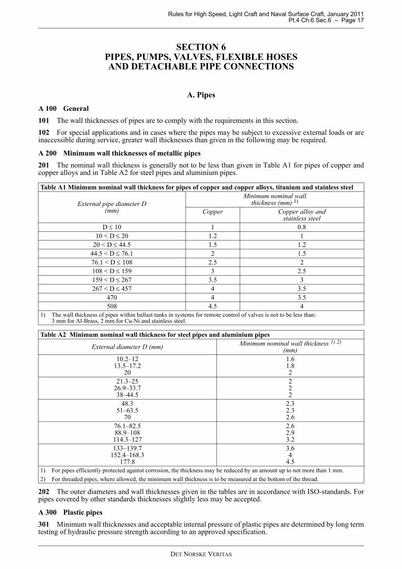
A 100 General101 The wall thicknesses of pipes are to comply with the requirements in this section.102 For special applications and in cases where the pipes may be subject to excessive external loads or areinaccessible during service, greater wall thicknesses than given in the following may be required.
A 200 Minimum wall thicknesses of metallic pipes201 The nominal wall thickness is generally not to be less than given in Table A1 for pipes of copper andcopper alloys and in Table A2 for steel pipes and aluminium pipes.
202 The outer diameters and wall thicknesses given in the tables are in accordance with ISO-standards. Forpipes covered by other standards thicknesses slightly less may be accepted.
A 300 Plastic pipes301 Minimum wall thicknesses and acceptable internal pressure of plastic pipes are determined by long termtesting of hydraulic pressure strength according to an approved specification.
Table A1 Minimum nominal wall thickness for pipes of copper and copper alloys, titanium and stainless steel
External pipe diameter D(mm)
Minimum nominal wallthickness (mm) 1)
Copper Copper alloy andstainless steel
D ≤ 10 1 0.810 < D ≤ 20 1.2 1
20 < D ≤ 44.5 1.5 1.244.5 < D ≤ 76.1 2 1.576.1 < D ≤ 108 2.5 2108 < D ≤ 159 3 2.5159 < D ≤ 267 3.5 3267 < D ≤ 457 4 3.5
470 4 3.5508 4.5 4
1) The wall thickness of pipes within ballast tanks in systems for remote control of valves is not to be less than:3 mm for Al-Brass, 2 mm for Cu-Ni and stainless steel.
Table A2 Minimum nominal wall thickness for steel pipes and aluminium pipes
External diameter D (mm) Minimum nominal wall thickness 1) 2)(mm)
10.2–1213.5–17.2
20
1.61.82
21.3–2526.9–33.738–44.5
222
48.351–63.5
70
2.32.32.6
76.1–82.588.9–108114.3–127
2.62.93.2
133–139.7152.4–168.3
177.8
3.64
4.51) For pipes efficiently protected against corrosion, the thickness may be reduced by an amount up to not more than 1 mm.2) For threaded pipes, where allowed, the minimum wall thickness is to be measured at the bottom of the thread.
DET NORSKE VERITAS
Rules for High Speed, Light Craft and Naval Surface Craft, January 2011 Pt.4 Ch.6 Sec.6 – Page 18
302 Evaluation of vacuum and external pressure resistance is necessary for plastic piping. Due to lowelasticity modulus the buckling stability may be critical in pipe systems where vacuum or external pressuresare to be expected.303 Temperature limits and pressure reductions are indicated in Tables A3 and A4. The limits may beextended on basis of acceptable documentation from the pipe manufacturer. The permissible temperatures arestated for long term service. Short periods of marginally higher temperatures may be accepted by case to caseconsiderations.304 The tables are related to water service only. Use for other media shall be considered case by case.305 If thermoplastic pipes are to be installed in external areas, the pipes shall either be particularly approvedfor external use or be protected against ultraviolet radiation.306 Plastic pipes are normally made of electrically insulating materials and are as such not acceptable forservice in gas hazardous areas. Special qualities can be permitted if they are documented to be electricallyconductive (antistatic) according to an approved specification.307 The need for expansion elements must be specially considered with respect to the large thermalexpansion coefficient of the plastic materials.308 Glassfibre reinforced epoxy and polyester pipes are considerably more exposed to damage from impactand local overloading than steel pipes. This must be duly taken into consideration by handling, installation andinspection.
DET NORSKE VERITAS
Rules for High Speed, Light Craft and Naval Surface Craft, January 2011 Pt.4 Ch.6 Sec.6 – Page 19
B. Pumps
B 100 General
101 The following pumps are to be delivered with the Society’s certificate:
— sea-water cooling pumps for main engine— fresh-water cooling pumps for main engine— fuel oil service pumps— fuel injection valve cooling pumps— lubricating oil pumps for main engine and main reduction gear— bilge pumps— ballast pumps— fire pumps and emergency fire pumps— other pumps considered necessary for performing of the main functions listed in Pt.1 Ch.1 Sec.2 A300.
Guidance note:The control and monitoring system for valves and pumps for systems listed in Sec.1 C102 is not required to bedelivered with NV product certificate.
---e-n-d---of---G-u-i-d-a-n-c-e---n-o-t-e---
B 200 Relief valves
201 Displacement pumps are to be fitted with relief valves. For pumps transporting flammable liquids, thedischarge from the relief valve is normally to be led back to suction side of the pump.
B 300 Hydrostatic tests
301 Pump housings are to be hydrostatically tested at a pressure of 1.5 times the maximum working pressure.However, the test pressure need not exceed the maximum working pressure by more than 70 bar.For centrifugal pumps the maximum pressure is to be the maximum pressure head on the head-capacity curve.For displacement pumps the maximum working pressure is not to be taken less than the relief valve openingpressure.
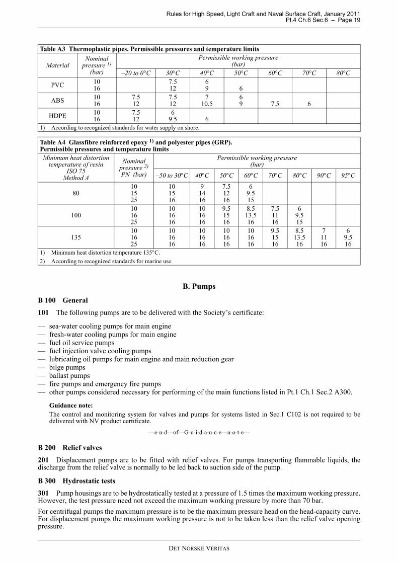
Table A3 Thermoplastic pipes. Permissible pressures and temperature limits
MaterialNominal
pressure 1) (bar)
Permissible working pressure(bar)
–20 to 0°C 30°C 40°C 50°C 60°C 70°C 80°C
PVC 1016
7.512
69 6
ABS 1016
7.512
7.512
710.5
69 7.5 6
HDPE 1016
7.512
69.5 6
1) According to recognized standards for water supply on shore.
Table A4 Glassfibre reinforced epoxy 1) and polyester pipes (GRP). Permissible pressures and temperature limitsMinimum heat distortion
temperature of resinISO 75
Method A
Nominalpressure 2) PN (bar)
Permissible working pressure(bar)
–50 to 30°C 40°C 50°C 60°C 70°C 80°C 90°C 95°C
80101525
101516
91416
7.51216
69.515
100101625
101616
101616
9.51516
8.513.516
7.51116
69.515
135101625
101616
101616
101616
101616
9.51516
8.513.516
71116
69.516
1) Minimum heat distortion temperature 135°C.2) According to recognized standards for marine use.
DET NORSKE VERITAS
Rules for High Speed, Light Craft and Naval Surface Craft, January 2011 Pt.4 Ch.6 Sec.6 – Page 20
B 400 Capacity tests401 Pump capacities are to be checked with the pump running at design condition (rated speed and pressurehead, viscosity, etc.)Capacity test may be dispensed with for pumps produced in series when previous satisfactory tests have beencarried out on similar pumps.For centrifugal pumps having capacities less than 1 000 m3/h, the pump characteristic (head-capacity curve) isto be determined for each type of pump. For centrifugal pumps having capacities equal to or greater than 1 000m3/h, the pump characteristic is to be determined over a suitable range on each side of the design point, for eachpump.402 Special survey arrangement for testing of pumps may be agreed upon.
C. ValvesC 100 Valve design101 Drawings and specifications are to be submitted for approval for valves of new type or unconventionaldesign and for valves of welded construction fitted on ship’s side and bottom.102 Pressure-temperature ratings for valves are to be in accordance with a recognized national standard.103 Screwed-on valve bonnets are not to be used for valves on craft’s side and bottom and for valves insystems for flammable fluids.104 Screwed-on valve bonnets are to be secured against loosening when the valve is operated.105 Valves are normally to be closed by turning the handwheel clockwise.106 Indicators are to be provided to show the open and closed position of the valve, unless this can beobserved in some other way, e.g. by a distinctly rising valve stem.107 Handles on cocks are to be removable only when the cocks are in closed position.108 Welded necks of valve bodies are to be sufficiently long to ensure that the valves are not distorted asresult of welding and subsequent heat treatment of the joints.
C 200 Hydrostatic tests201 All valve bodies are to be subjected by the manufacturer to a hydrostatic test at a pressure equal to 1.5times the nominal pressure (the nominal pressure is the maximum allowable working pressure at roomtemperature). The test pressure need not be more than 70 bar in excess of the nominal pressure.For valves fitted on craft’s side and bottom the test pressure is not to be less than 5 bar.202 Butterfly valves fitted on craft’s side and bottom are also to be hydrostatically tested at a pressure equalto 5 bar applied independently on each side of the closed disc.203 For valves fitted on craft’s side and bottom, the hydrostatic test is to be carried out in the presence of thesurveyor or according to a special agreement (MSA).204 For valves other than those mentioned in 203, the manufacturer’s certificate for hydrostatic testing willbe accepted.
D. Flexible HosesD 100 General101 Flexible hoses with couplings are to be of DNV approved type.102 Hoses of non-metallic materials used in systems containing flammable fluids or sea water are to have atleast one ply internal wire braid.103 In fresh cooling water lines for diesel engines and compressors the requirements in 101 and 102 may bedispensed with provided each engine is arranged with an independent cooling system. Short rubber hoses withinternal textile reinforcement fitted by means of hose clamps may be accepted.104 Every hose is to be hydrostatically tested at a hydrostatic pressure of 1.5 times the working pressure.
D 200 Installation201 Flexible hoses are to be accessible for inspection.
DET NORSKE VERITAS
Rules for High Speed, Light Craft and Naval Surface Craft, January 2011 Pt.4 Ch.6 Sec.6 – Page 21
202 Flexible hoses except for short lengths are to be continuously supported along their length.
E. Detachable Pipe ConnectionsE 100 Flange connections101 Flanges with their pressure-temperature ratings in accordance with a recognized national standard willnormally be accepted.
E 200 Screwed pipe couplings201 Bite and compression type couplings and couplings with brazing (only for copper and copper alloys) andwelding cones according to a recognized standard may be used for pipes with an outer diameter 51 mm and less.202 Threaded joints may be used for pipes with an outer diameter 60.3 mm and less with the exclusion ofpipes containing flammable fluids and pipes in systems with design pressure above 16 bar.
Guidance note:Threaded joint is defined as a joint where packed threads perform the sealing.
---e-n-d---of---G-u-i-d-a-n-c-e---n-o-t-e---
E 300 Expansion joints and bellows301 Expansion joints and bellows are subject to approval for their intended use. The joints and bellows areto be so designed and installed that pulling or blowing out is prevented.The pipeline in which an expansion joint or bellow is to be fitted, is to be adequately adjusted, aligned andclamped. When found necessary, protection against mechanical damage of the expansion joints may berequired.302 The positions of expansion joints and bellows are to be clearly shown in the drawing of the pipingsystems.303 Expansion joints and bellows are in general only to be used in readily accessible spaces. Exceptions tothe above are ballast tanks and pipe tunnels.
DET NORSKE VERITAS
Rules for High Speed, Light Craft and Naval Surface Craft, January 2011 Pt.4 Ch.6 Sec.7 – Page 22
SECTION 7 MANUFACTURE, WORKMANSHIP, INSPECTION AND TESTING
A. Joining of Plastic PipesA 100 General101 Joining of plastic pipes by welding, gluing, cementing, lamination or similar methods is to be carried outby qualified personnel certified by the pipe manufacturer.102 Satisfactory education and training is to be documented by a certificate issued by the pipe manufacturer.The certificate is to contain:
— the name of the holder— a statement confirming that the holder is considered qualified for a specified type of joining— reference to the pipe manufacturer’s joining procedure— date of issue and validity period— piping manufacturer’s stamp and signature of responsible person.
103 Prior to installation each operator is to, at the location, make at least one test joint representative of thejoints to be used in the system. The ends of the joined pipe section are to be closed by flanges if such are includedin the pipe system. The joined pipe section is to be exposed to an inside destructive hydrostatic pressure test of 5times the design pressure of the pipe system, but not lower than 30 bars, for minimum 5 minutes. There is to beno visual crazing, cracking or leakage. Special care is to be taken to inspect for «weeping» (sweating of waterthrough the pipe wall). The procedure test is to be surveyed and approved by the Society.
B. Welding and BrazingB 100 General101 Welding of joints is to be carried out by qualified welders using approved welding procedures andwelding consumables.102 Brazing of joints is to be carried out by qualified brazers using approved brazing procedures.
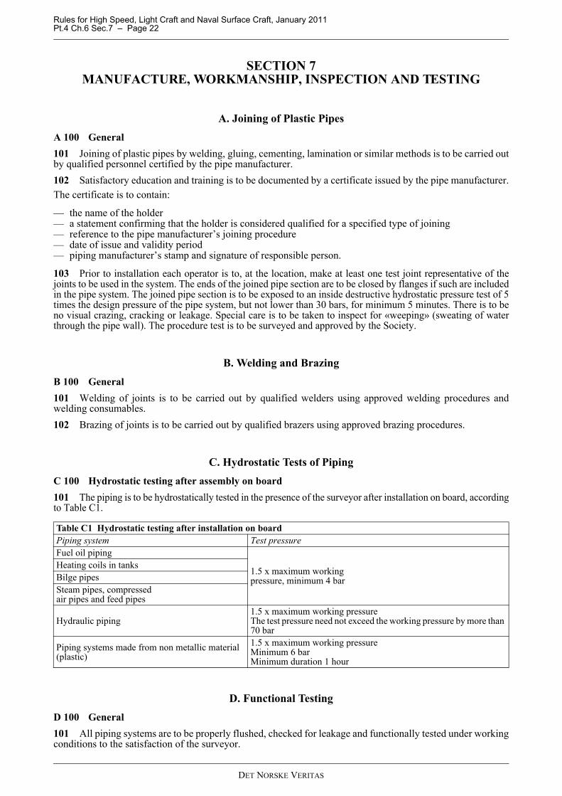
C. Hydrostatic Tests of PipingC 100 Hydrostatic testing after assembly on board101 The piping is to be hydrostatically tested in the presence of the surveyor after installation on board, accordingto Table C1.
D. Functional TestingD 100 General101 All piping systems are to be properly flushed, checked for leakage and functionally tested under workingconditions to the satisfaction of the surveyor.
Table C1 Hydrostatic testing after installation on boardPiping system Test pressureFuel oil piping
1.5 x maximum workingpressure, minimum 4 bar
Heating coils in tanksBilge pipesSteam pipes, compressedair pipes and feed pipes
Hydraulic piping1.5 x maximum working pressureThe test pressure need not exceed the working pressure by more than 70 bar
Piping systems made from non metallic material(plastic)
1.5 x maximum working pressureMinimum 6 barMinimum duration 1 hour
DET NORSKE VERITAS
Rules for High Speed, Light Craft and Naval Surface Craft, January 2011 Pt.4 Ch.6 Sec.7 – Page 23
E. Non-Destructive TestingE 100 General101 In general, the welded joints including the inside wherever possible shall be visually examined. Non-destructive tests will be required for pipes with outer diameter greater than 76.1 mm as indicated below:Butt welded jointsFor pipes containing flammable fluids or steam with design pressure above 7 bar, or other media with designpressure above 16 bar, at least 10% random radiographic testing.Fillet weldsFor pipes containing flammable fluids or steam with design pressure above 7 bar, or other media with designpressure above 16 bar, at least 10% random magnetic particle testing.