71
Drilling Arne Lislerud

Drilling Arne Lislerud
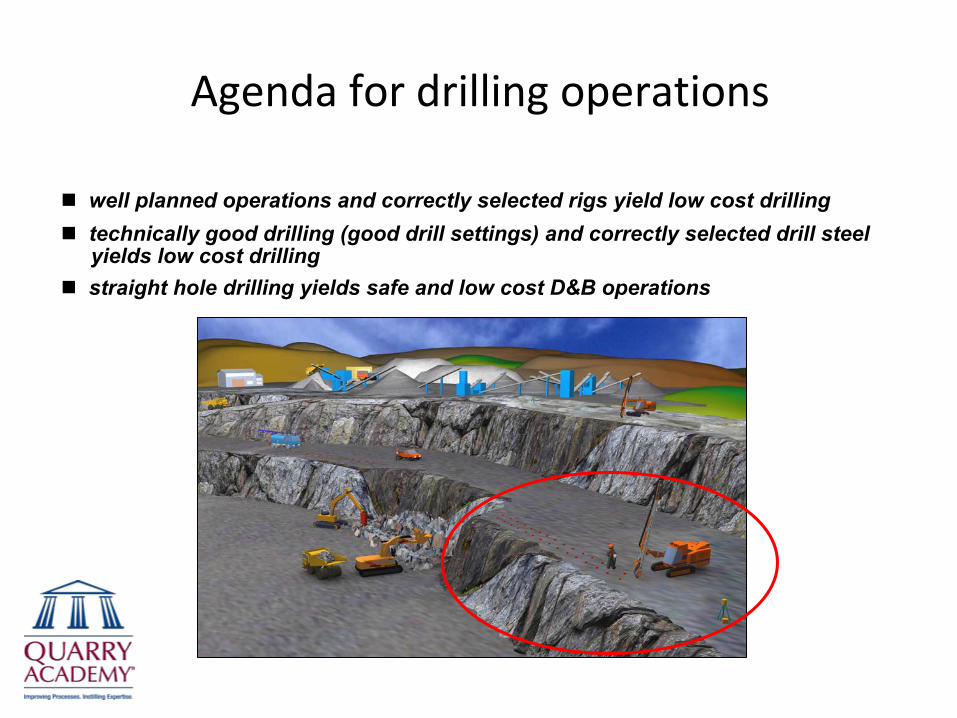
Agenda for drilling operations
well planned operations and correctly selected rigs yield low cost drillingtechnically good drilling (good drill settings) and correctly selected drill steelyields low cost drillingstraight hole drilling yields safe and low cost D&B operations

The most common drilling methods in use
Top Hammer(hydraulic or pneumatic)
Down-the-Hole(pneumatic)
Rotary(roller bits)
Rotary(drag bits)
- 120,000
- 100,000
- 80,000
- 60,000
- 40,000
- 20,000
50,000 -
40,000 -
30,000 -
20,000 -
10,000 -Uni
axia
l com
pres
sive
str
engt
h, U
CS
(psi
)
Rot
ary
pulld
own
(lbs)
I I I I I I I I I I I I I I I1 2 3 4 5 6 7 8 9 10 11 12 13 14 15 "25 51 76 102 127 152 178 203 229 254 279 305 330 356 381 mm
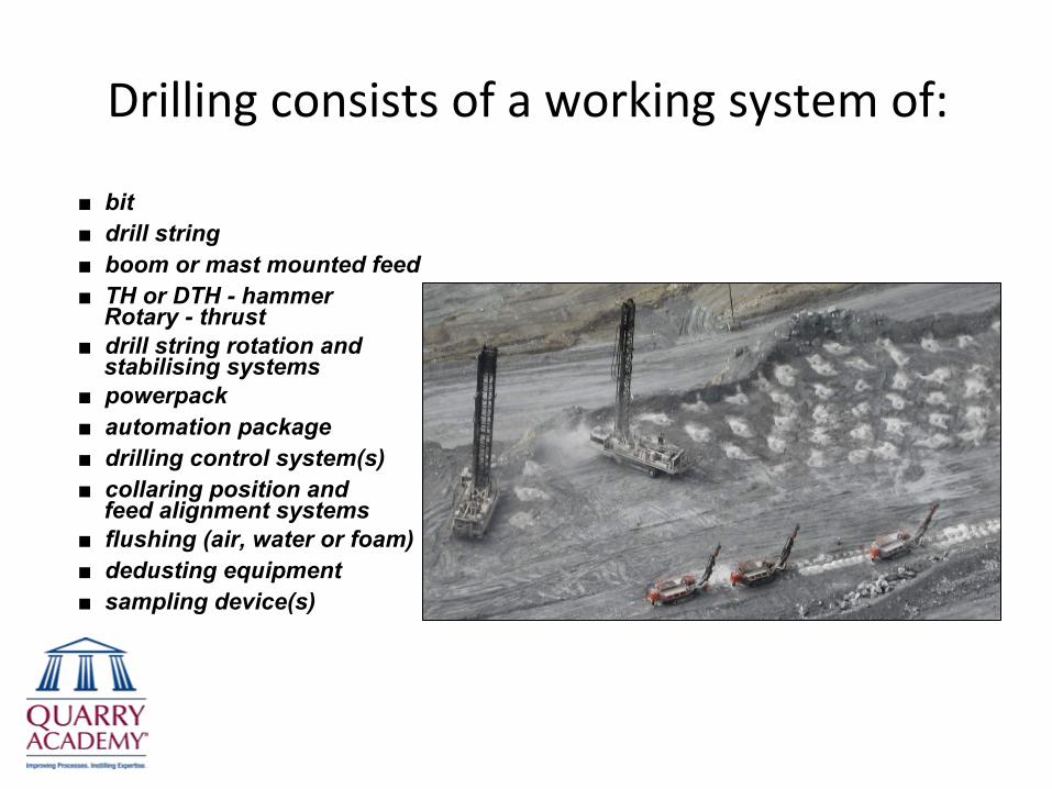
Drilling consists of a working system of:
■
bit■
drill string■
boom or mast mounted feed■
TH or DTH -
hammerRotary - thrust
■
drill string rotation andstabilising systems
■
powerpack■
automation package■
drilling control system(s)■
collaring position and feed alignment systems
■
flushing (air, water or foam)■
dedusting equipment■
sampling device(s)
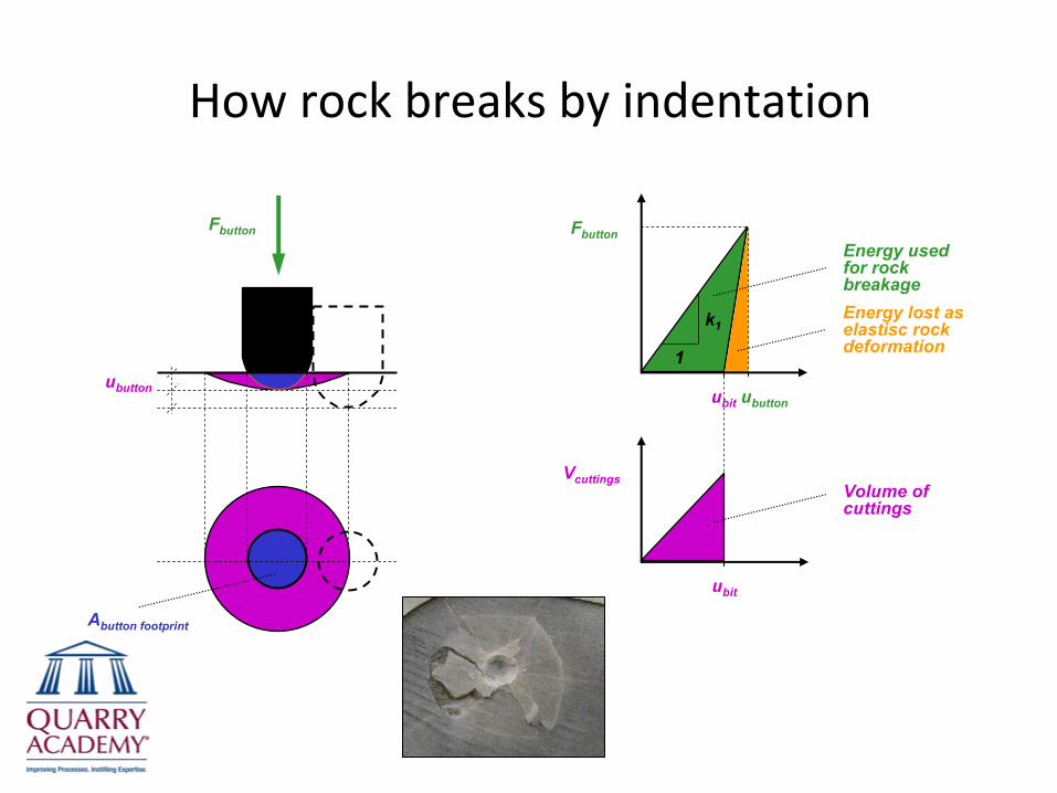
How rock breaks by indentation
ubutton
Fbutton
ubit
Vcuttings
Abutton footprint
Fbutton
ubutton
Volume of cuttings
Energy used for rock breakage
1
ubit
k1Energy lost as elastisc rock deformation

Chipping – as the button is off‐loaded
5 mm
Off-loading fractures at ( 2 ) which create
cuttings by chip spalling
Chipping around the button footprint area
On-loading fractures created at ( 1 )
ubutton
Fbit ( 1 )
( 2 )
k1
1

Chip formation by bit indentation and button indexing
Spray paint applied between bit impacts
Chipping around button footprint
Button footprint
Ø76mm/3”
Direction of bit rotation
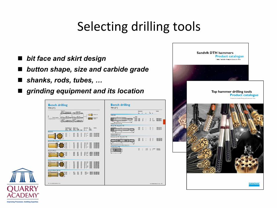
Selecting drilling tools
bit face and skirt designbutton shape, size and carbide gradeshanks, rods, tubes, …grinding equipment and its location
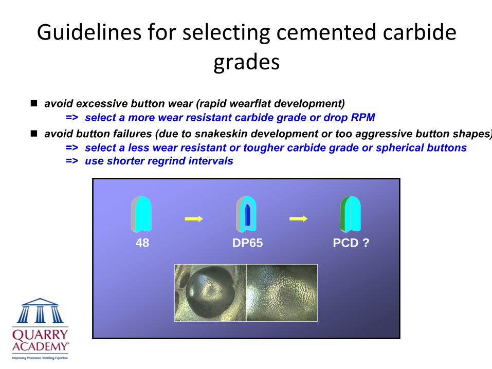
Guidelines for selecting cemented carbide grades
avoid excessive button wear (rapid wearflat development)=> select a more wear resistant carbide grade or drop RPM
avoid button failures (due to snakeskin development or too aggressive button shapes)=> select a less wear resistant or tougher carbide grade or spherical buttons=> use shorter regrind intervals
PCD ?48 DP65
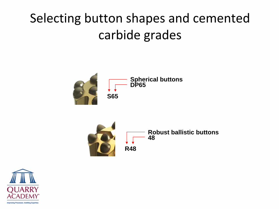
Selecting button shapes and cemented carbide grades
R48
Robust ballistic buttons48
S65
Spherical buttonsDP65
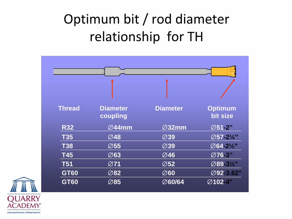
Optimum bit / rod diameter relationship for TH
Thread Diameter Diameter Optimumcoupling bit size
R32 ∅44mm ∅32mm ∅51-2”T35 ∅48 ∅39 ∅57-2¼”T38 ∅55 ∅39 ∅64-2½”T45 ∅63 ∅46 ∅76-3”T51 ∅71 ∅52 ∅89-3½”GT60 ∅82 ∅60 ∅92-3.62”GT60 ∅85 ∅60/64 ∅102-4”

Optimum bit / guide or pilot (lead) tube relationship for TH
Thread Diameter Diameter Optimumcoupling bit size
T38 ∅55mm ∅56mm ∅64-2½”T45 ∅63 ∅65 ∅76-3”T51 ∅71 ∅76 ∅89-3½”GT60 ∅85 ∅87 ∅102-4”GT60 ∅85 ∅102 ∅115-4½”
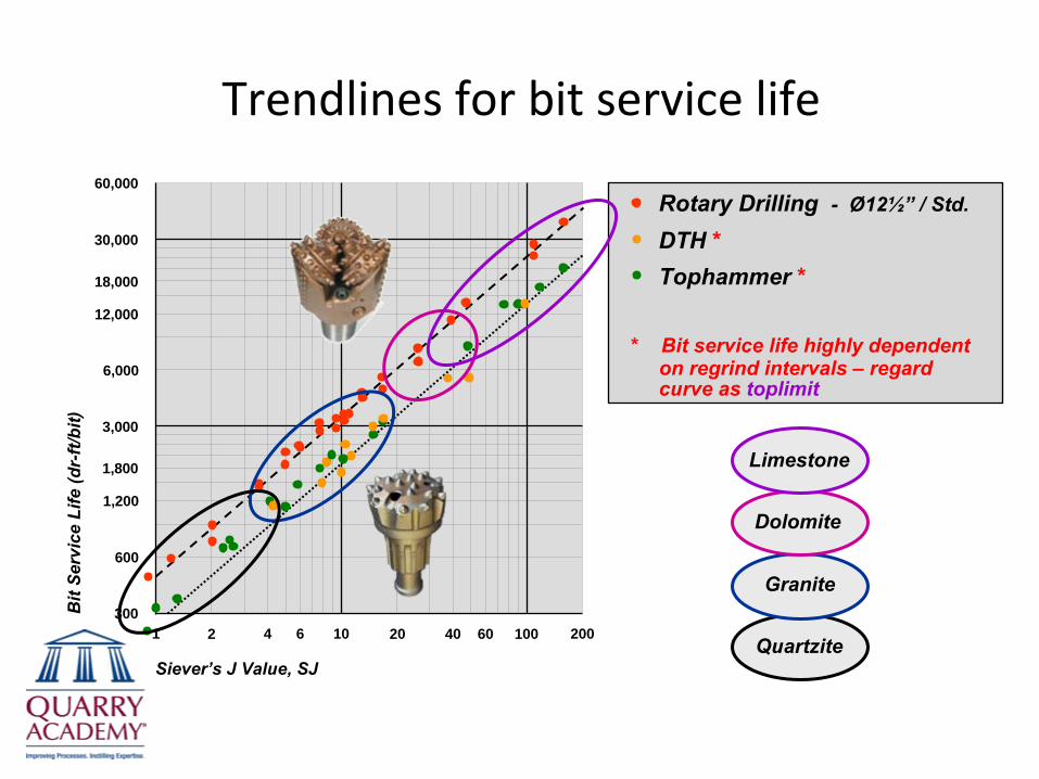
Trendlines for bit service life
102 4 61 2004020 10060
3,000
6,000
1,800
1,200
600
300
12,000
18,000
30,000
60,000
Siever’s J Value, SJ
Bit
Serv
ice
Life
(dr-
ft/bi
t)
Rotary Drilling -
Ø12½”
/ Std.
DTH *Tophammer *
* Bit service life highly dependenton regrind intervals – regardcurve as toplimit
Limestone
Dolomite
Granite
Quartzite

Relationship between SJ and VHNR
rock surface hardness, VHNRrock surface hardness, SJ
Vickers Hardness Number Rock, VHNR
700500400300200100 1000 1500
Non-weatheredrock
Weathered rock
Rock with "zero"grain bonding
Siev
ers
J Va
lue,
SJ
100
2
3
5
4
6
87
910
20
30
40
5060
8070
90
200
300
400
500600
800900
1000
700
0.5
0.4
0.6
0.80.7
0.91
chuck
guidetungsten carbide bit
guide
200 revs
8.5mm 110g
20 kg
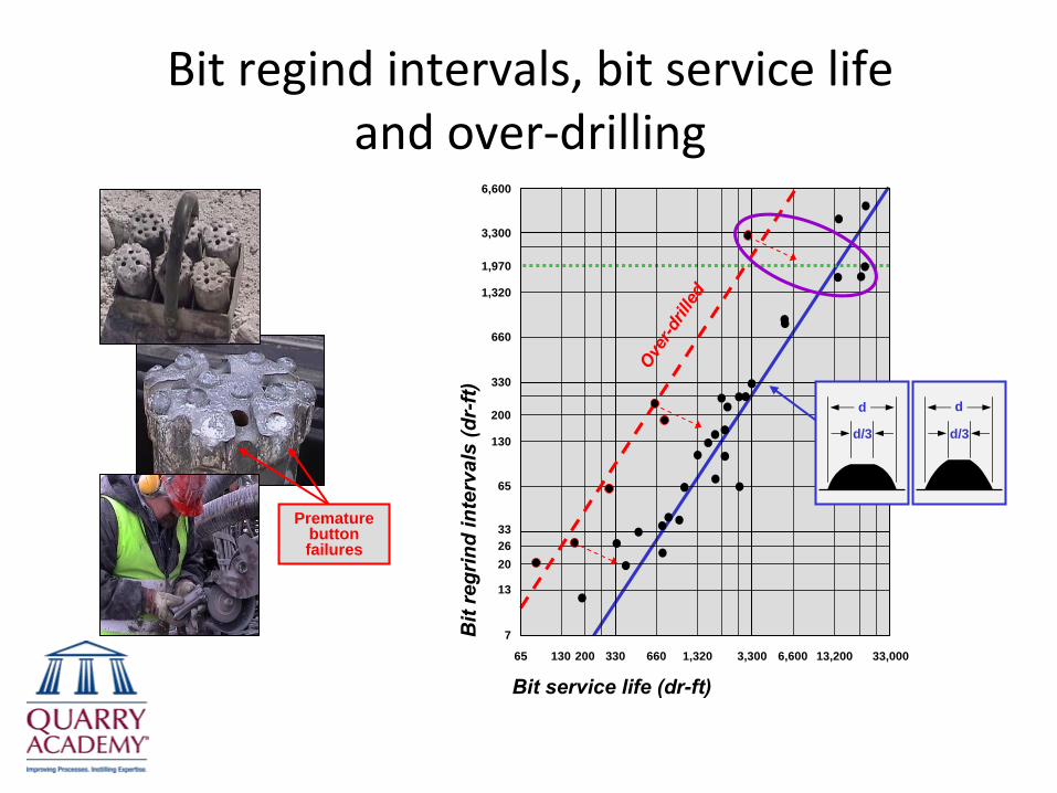
Bit regind intervals, bit service life and over‐drilling
33,0003,30033065 130 200
Bit service life (dr-ft)
Bit
regr
ind
inte
rval
s (d
r-ft)
6,600
3,300
7
33
330
13
2620
660
1,320
130
65
660 1,320 6,600 13,200Ove
r-dril
led
Premature button failures
d d
d/3 d/3
1,970
200
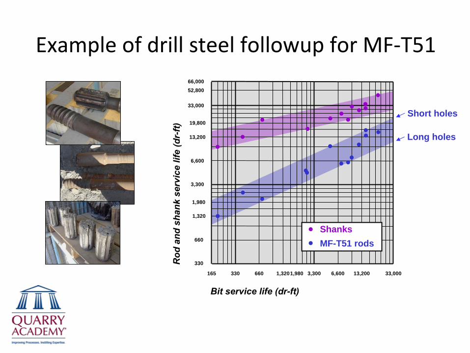
Example of drill steel followup for MF‐T51
ShanksMF-T51 rods
330
Bit service life (dr-ft)
Rod
and
sha
nk s
ervi
ce li
fe (d
r-ft)
165 3,3001,320 33,000660 6,600
3,300
330
33,000
Short holes
Long holes
6,600
13,200
66,000
13,2001,980
19,800
1,320
1,980
660
52,800
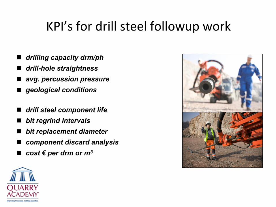
KPI’s for drill steel followup work
drilling capacity drm/phdrill-hole straightnessavg. percussion pressuregeological conditions
drill steel component lifebit regrind intervalsbit replacement diametercomponent discard analysiscost € per drm or m3

Flushing of drill‐cuttings
Insufficient air < 50 ft/slow bit penetration ratespoor percussion dynamicsinterupt drilling to clean holesplugged bit flushing holesstuck drill steel”circulating” big chip wear
Too much air > 100 m/sexcessive drill steel wearerosion of hole collaring pointextra dust emissionsincreased fuel consumption
Correction factorshigh density rockbadly fractured rock(air lost in fractures- use water or foam tomud up hole walls)high altitude(low density air)large chips
Flift
GFlift
G
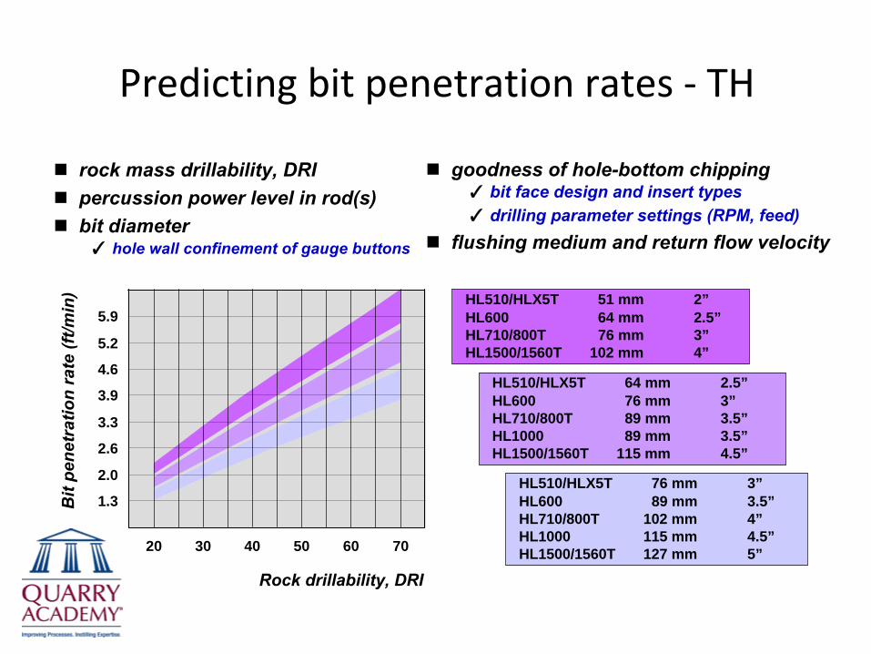
Predicting bit penetration rates ‐
TH
rock mass drillability, DRIpercussion power level in rod(s)bit diameter✓ hole wall confinement of gauge buttons
goodness of hole-bottom chipping✓ bit face design and insert types✓ drilling parameter settings (RPM, feed)
flushing medium and return flow velocity
Rock drillability, DRI
20 30 40 50 60
Bit
pene
trat
ion
rate
(ft/m
in)
1.3
2.6
3.9
5.2
70
HL510/HLX5T 51 mm 2”HL600 64 mm 2.5”HL710/800T 76 mm 3”HL1500/1560T 102 mm 4”
2.0
3.3
4.6
5.9
HL510/HLX5T 64 mm 2.5”HL600 76 mm 3”HL710/800T 89 mm 3.5”HL1000 89 mm 3.5”HL1500/1560T 115 mm 4.5”
HL510/HLX5T 76 mm 3”HL600 89 mm 3.5”HL710/800T 102 mm 4”HL1000 115 mm 4.5”HL1500/1560T 127 mm 5”
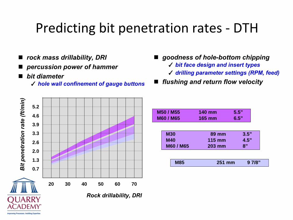
Predicting bit penetration rates ‐
DTH
rock mass drillability, DRIpercussion power of hammerbit diameter✓ hole wall confinement of gauge buttons
goodness of hole-bottom chipping✓ bit face design and insert types✓ drilling parameter settings (RPM, feed)
flushing and return flow velocity
Rock drillability, DRI
20 30 40 50 60
Bit
pene
trat
ion
rate
(ft/m
in)
0.7
2.0
3.3
4.6
70
M50 / M55 140 mm 5.5”M60 / M65 165 mm 6.5”
1.3
2.6
3.9
5.2
M30 89 mm 3.5”M40 115 mm 4.5”M60 / M65 203 mm 8”
M85 251 mm 9 7/8”

Gross drilling capacities (dr‐ft/h)
rig setup and feed alignment time per drill-holecollaring time through overburden or sub-drill zonedrill-hole wall stabilisation time (if required)rod handling times (unit time and rod count)bit penetration rate loss percentage i.e.
✓
rods and couplings 6.1 % per rod✓
MF rods
3.6 % per rod✓
tubes
2.6 % per tube
effect of percussion power levels on:✓
bit penetration rates✓
drill steel service life✓
drill-hole straightness
rig tramming times between benches, refueling, etc.effect of operator work environment on effectivework hours per shiftrig availability, service availability, service andmaintenance intervals
Poor net drilling capacities for:✓
very broken rock✓ terrain benches - winching✓ very low or very high benches✓
very poor collaring conditions
Bit penetration rate, BPR2
(ft/min)
Gro
ss d
rillin
g ca
paci
ty (d
r-ft
/ hou
r)2.0 2.6 3.3 3.9 4.6 5.2 5.9
32.5
65
100
130
165
195
230
Typical breakdown of longterm rig usage and capacities
Shift time, 100 %
Mechanical availability, 80 -
90 %
Machine utilisation, 60 -
80 %
Net drilling time, 40 –
60 %
Bit penetration time
engine hours
percussion hours(30 -
60 % of engine hours)
net drilling hours
shift hours
Rod handlingHole stabilisationReposition rig and feedBit change…
Shift changeLunchBlast downtimeSet out pattern…
Daily serviceScheduledmaintenanceBreakdowns…
Set out TIMTrammingRefuelingNew set rods…

Mechanics of percussive drilling
Percussive drilling
� Down-the-hole, DTHStress waves transmitted directly through bit into rock
� TophammerStress wave energy transmitted through shank, rods, bit, and then into rock
Basic functions
� percussion
-
reciprocating piston used to producestress waves to power rock indentation
� feed
-
provide bit-rock contact at impact� rotation
-
provide bit impact indexing� flushing
-
cuttings removal from hole bottom� foam flushing
-
drill-hole wall stabilisation
FEED
PERCUSSION
CUTTINGS
FLUSHING
ROTATION
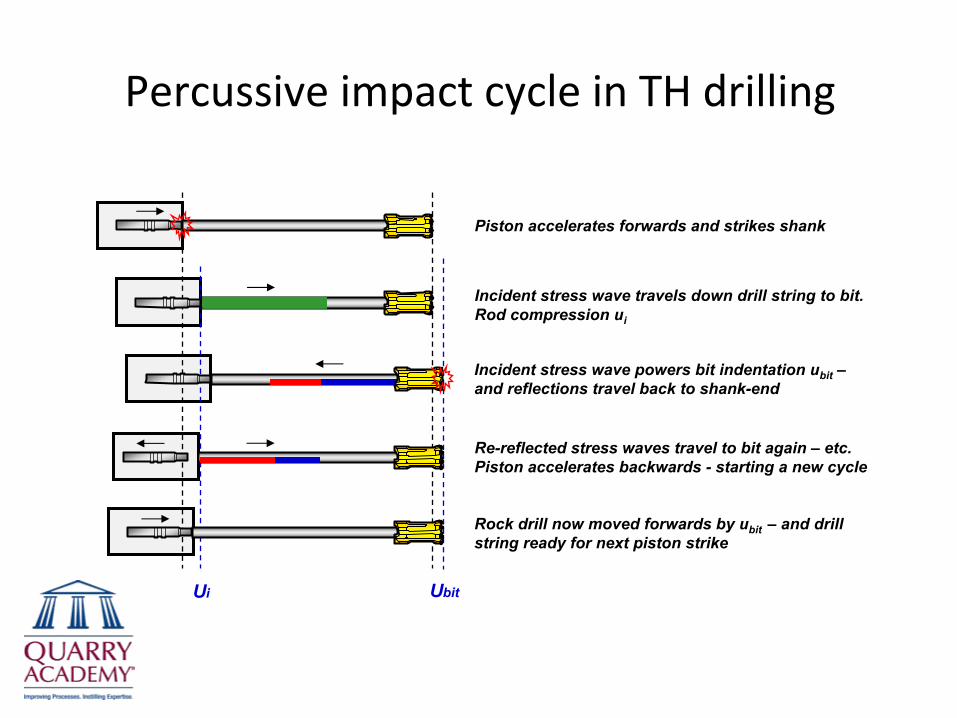
Percussive impact cycle in TH drilling
Ui Ubit
Piston accelerates forwards and strikes shank
Incident stress wave travels down drill string to bit. Rod compression ui
Incident stress wave powers bit indentation ubit
–
and reflections travel back to shank-end
Re-reflected stress waves travel to bit again –
etc. Piston accelerates backwards -
starting a new cycle
Rock drill now moved forwards by ubit –
and drill string ready for next piston strike
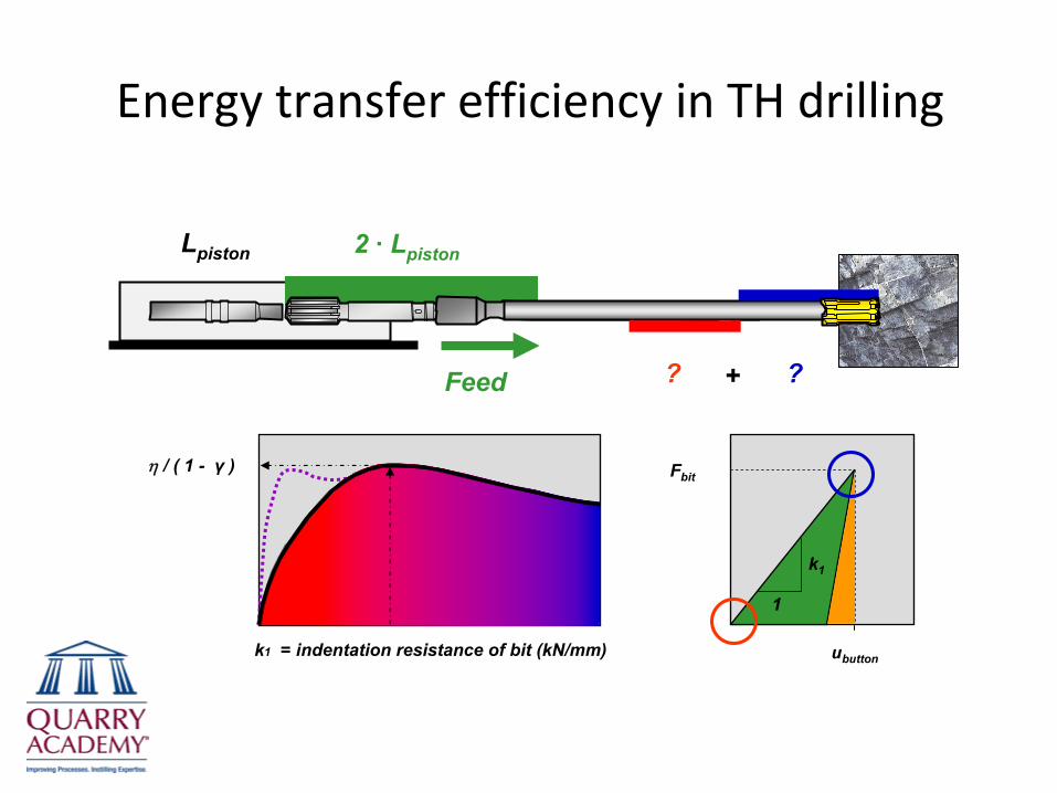
Energy transfer efficiency in TH drilling
ubutton
Fbit
1
k1
= indentation resistance of bit (kN/mm)
η / ( 1 -
γ
)
k1
Feed
2 ·
Lpiston
??
Lpiston
+
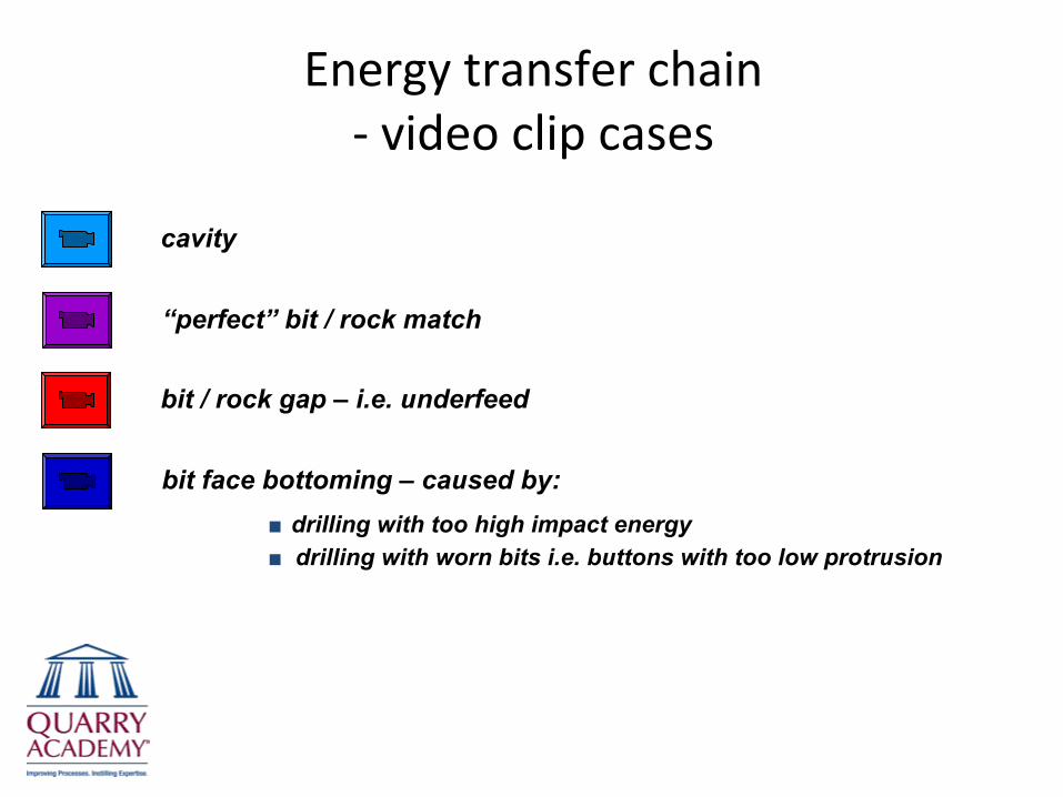
Energy transfer chain ‐
video clip cases
cavity
bit face bottoming –
caused by:■
drilling with too high impact energy■
drilling with worn bits i.e. buttons with too low protrusion
bit / rock gap –
i.e. underfeed
“perfect”
bit / rock match
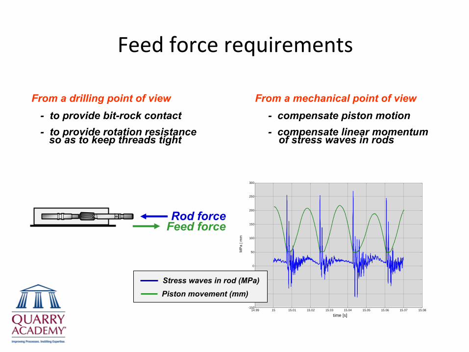
Feed force requirements
From a drilling point of view
From a mechanical point of view-
to provide bit-rock contact
-
compensate piston motion-
to provide rotation resistance
-
compensate linear momentumso as to keep threads tight of stress waves in rods
14.99 15 15.01 15.02 15.03 15.04 15.05 15.06 15.07 15.08-150
-100
-50
0
50
100
150
200
250
300
MP
a | m
m
time [s]
Feed forceRod force
Stress waves in rod (MPa)Piston movement (mm)
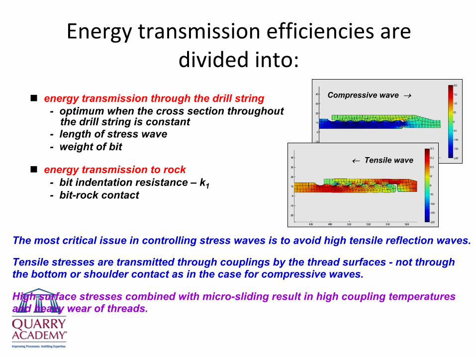
Energy transmission efficiencies are divided into:
← Tensile wave
Compressive wave →energy transmission through the drill string-
optimum when the cross section throughout the drill string is constant
-
length of stress wave-
weight of bit
energy transmission to rock-
bit indentation resistance –
k1-
bit-rock contact
The most critical issue in controlling stress waves is to avoid high tensile reflection waves.
Tensile stresses are transmitted through couplings by the thread
surfaces -
not throughthe bottom or shoulder contact as in the case for compressive waves.
High surface stresses combined with micro-sliding result in high coupling temperaturesand heavy wear of threads.

Matching drill settings to site conditions
Chipping during bit indentationRock hardnessButton count and size
( and bit size )
Same bit in 2 different rock types or quarries
k1-good rockk1-soft
k1-soft k1-good rock
ηsingle pass
BPR ratio}
Feed ratio( pfeed
/ pperc. )ubutton
Fbit
1k1-soft
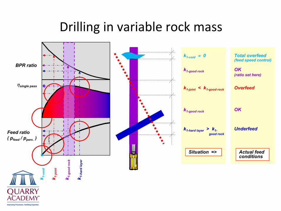
Drilling in variable rock mass
k1-void
≈ 0
k1-good rock
k1-joint
< k1-good rock
k1-good rock
k1-hard layer
> k1-good rock
Total overfeed(feed speed control)
OK(ratio set here)
Overfeed
OK
Underfeed
Actual feed conditions
Situation =>k1-soft k1-good rock
Feed ratio( pfeed
/ pperc. )
ηsingle pass
BPR ratiok 1
-goo
d ro
ck
k 1-h
ard
laye
r
k 1-jo
int
k 1-v
oid
}}

Ranger DX700 and 800 / Pantera DP1500
vgauge
(ft/s)
2nd
coup
ling
tem
pera
ture
, °F
1.0 1.2 1.4 1.5 1.7 1.9 2.1
100
140
180
210
250
285
UF
Drilling with disabled stabilizer
Baseline for stabilizer drills = ?
79 92 105 118 132 145 1586667 79 90 101 112 125 13556
RPM for Ø76mm –
3”
47 55 63 71 79 87 953939 46 53 59 66 72 7933
RPM for Ø89mm –
3½”
RPM for Ø127mm –
5”RPM for Ø152mm –
6”
0.85
HL700 + OMR50 HL700 +
Poclain MS 05
59 69 78 88 98 108 11849 RPM for Ø102mm –
4”
vgauge
= π d ·
RPM / ( 60·1000 )
R7002 / Poclain / Ø76 mm / MF-T45 / Otava
R700 / Ø76 mm / MF-T45 / Toijala
R700 / Ø70-89 mm / MF-T45 / Croatia
R8002 / HL800T / Ø76 mm / MF-T45 / Savonlinna
P1500 / Ø152 mm / MF-GT65 / Myllypuro
P1500 / Ø127 mm / MF-GT60 / Baxter-Calif.
70
HL800T + Calzone MR450

Summary of drill settings ‐
TH
higher percussion pressure => penetration rates increase proportionally with percussion power=> more drill steel breakage if …=> deviation increases with percussion energy
feed ratio ( Pfeed / Ppercussion )=> ratio controls average feed levels=> UF reduces drill steel life (heats up threads)=> OF increases deviation (especially bending)
higher rotation pressure => tightens threads (open threads reduce drill steel life)=> increases with OF=> increases with drill string bending
higher bit RPM => increases gauge button wear (especially in abrasive rocks)=> increases indexing of button footprints on drill hole bottom=> straighter holes=> higher thread temperatures
bits => select bits with regard to penetration rates, hole straightness,stabile drilling (percussion dynamics), price, …
=> bit condition / regrind intervals / damage to rock drill

How do we go about drilling straighter holes?
understand the many issues leading to drill-hole deviationtechnically good drill stringtechnically good drill rig, instrumentation, …motivate the drillers!
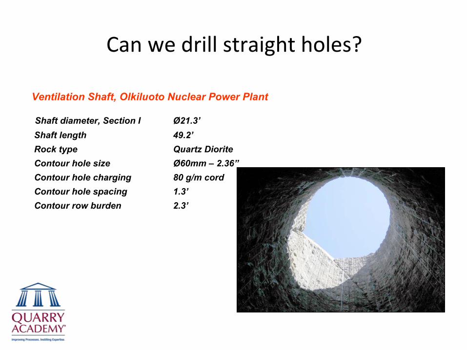
Can we drill straight holes?
Ventilation Shaft, Olkiluoto Nuclear Power Plant
Shaft diameter, Section I
Ø21.3’Shaft length
49.2’Rock type
Quartz DioriteContour hole size
Ø60mm –
2.36”Contour hole charging
80 g/m cordContour hole spacing
1.3’Contour row burden
2.3’
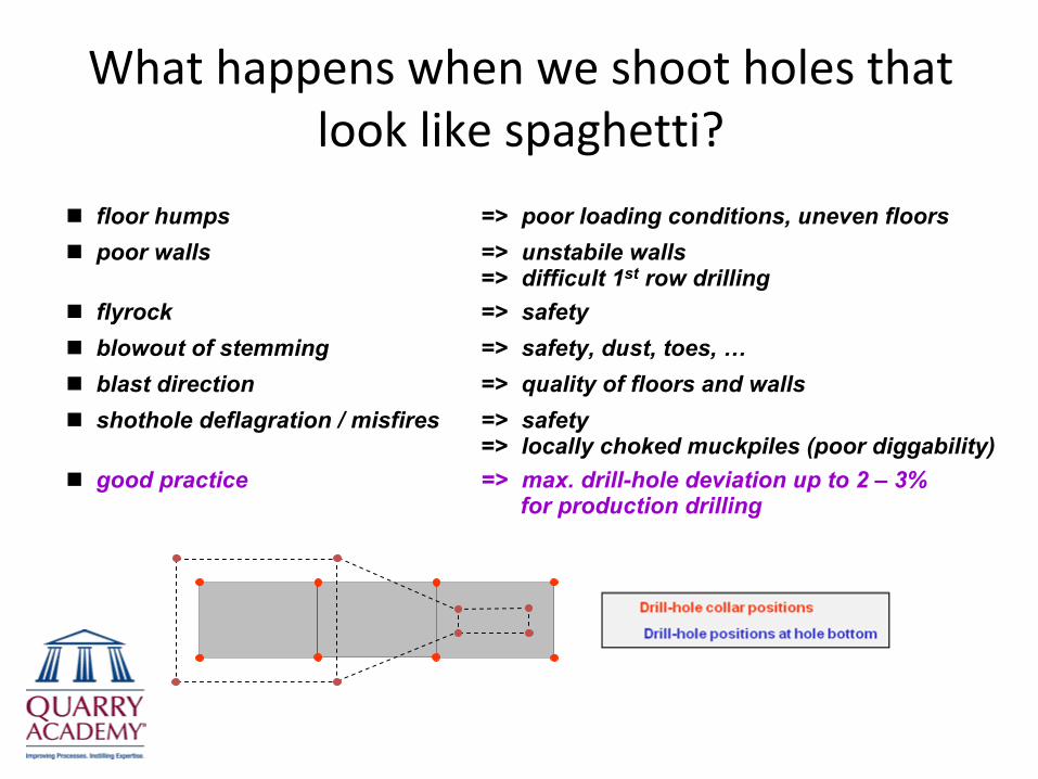
What happens when we shoot holes that look like spaghetti?
floor humps => poor loading conditions, uneven floorspoor walls => unstabile walls
=> difficult 1st row drillingflyrock => safety blowout of stemming => safety, dust, toes, …blast direction => quality of floors and wallsshothole deflagration / misfires => safety
=> locally choked muckpiles (poor diggability) good practice => max. drill-hole deviation up to 2 – 3%
for production drilling

Accurate drilling gives effective blasting
Sources of drilling error1. Collar position2. Hole inclination and direction3.
Deflection4.
Hole depth5.
Omitted or lost holes6.
Shothole diameter (worn out bits)
4
4
2
5
3
1
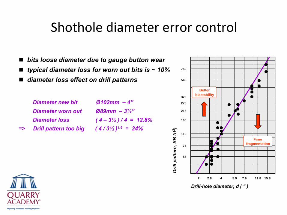
Shothole diameter error control
bits loose diameter due to gauge button weartypical diameter loss for worn out bits is ~ 10%diameter loss effect on drill patterns
Diameter new bit Ø102mm –
4”Diameter worn out Ø89mm –
3½”Diameter loss ( 4 –
3½
) / 4 = 12.8%=> Drill pattern too big ( 4 / 3½
)1.6
= 24%
2 4 5.9 7.92.8 11.8 15.8
110
75
55
750
160
215
270
540
320
Drill-hole diameter, d ( " )
Dril
l pat
tern
, SB
(ft2 )
Finer fragmentation
Finer fragmentation
Better blastability
Better blastability

Collar position error control
Difficult 1st row drilling
use tape, optical squares or alignmentlasers for measuring in collar positionsuse GPS or total stations to measure incollar positionscollar positions should be marked usingpainted lines –
not movable objects suchas rocks etc.completed drillholes should be protected by shothole plugs etc. to prevent holesfrom caving in (and filling up)use GPS guided collar positioning devicese.g. TIM-3D
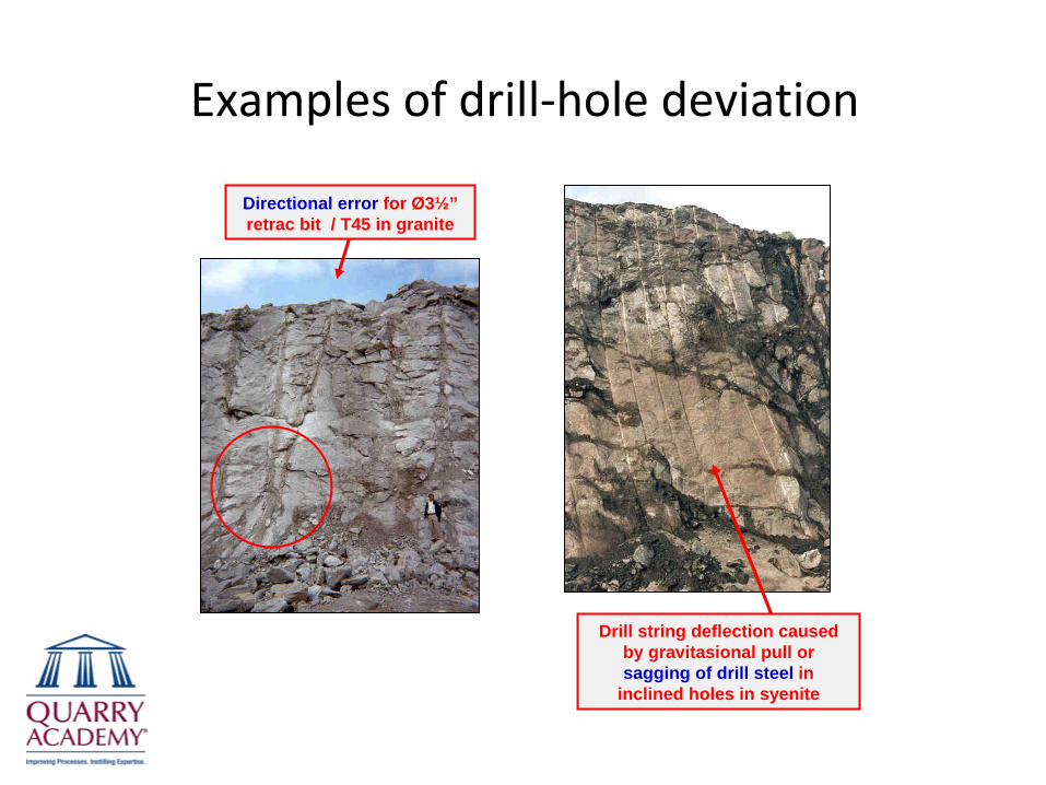
Examples of drill‐hole deviation
Directional error for Ø3½” retrac bit / T45 in granite
Drill string deflection caused by gravitasional pull or sagging of drill steel in
inclined holes in syenite

Examples of drill‐hole deviation
Deflection with and without pilot tube for Ø3½” DC retrac
bit / T51 in mica schist
Floor hump due to explosives malfunction – caused by drill string
deflection
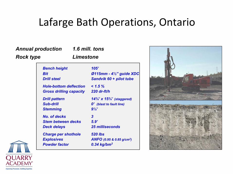
Lafarge Bath Operations, Ontario
Bench height
105’Bit
Ø115mm -
4½”
guide XDCDrill steel
Sandvik 60 + pilot tube
Hole-bottom deflection
< 1.5 %Gross drilling capacity
220 dr-ft/h
Drill pattern
14¾’
x 15¾’
(staggered)Sub-drill
0’
(blast to fault line)Stemming
9¼’
No. of decks
3Stem between decks
5.9’Deck delays
25 milliseconds
Charge per shothole
520 lbsExplosives
ANFO (0.95 & 0.85 g/cm3)Powder factor
0.34 kg/bm3
Annual production
1.6 mill. tonsRock type
Limestone
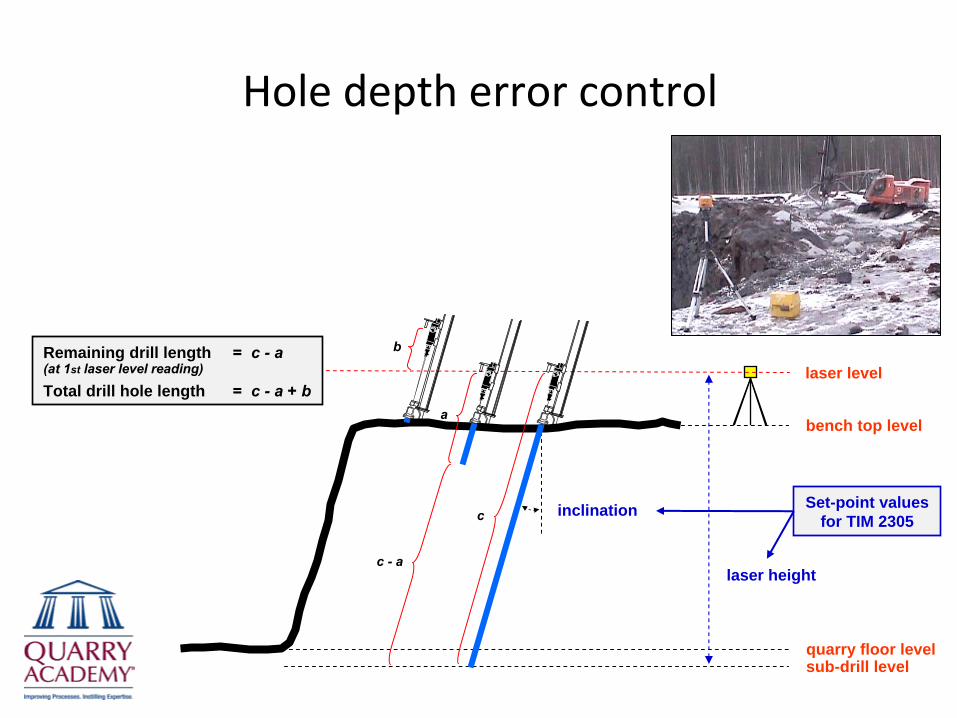
Hole depth error control
laser level
quarry floor levelsub-drill level
bench top level
inclination Set-point values for TIM 2305
b
a
c
c -
a
Remaining drill length = c -
a(at 1st laser level reading)
Total drill hole length = c -
a + b
laser height

Inclination and directional error control
quarry floor levelsub-drill level
bench top level
inclinationSet-point values for TIM 2305
✓ inclination✓ blast direction projection✓ distant aiming point direction
(new aiming point readingrequired when tracks are moved)
blast direction
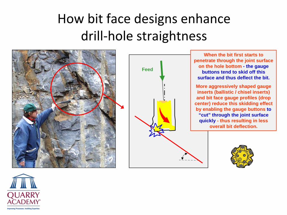
How bit face designs enhance drill‐hole straightness
�
Feed
When the bit first starts to penetrate through the joint surface
on the hole bottom - the gauge buttons tend to skid off this
surface and thus deflect the bit.
More aggressively shaped gauge inserts (ballistic / chisel inserts) and bit face gauge profiles (drop
center) reduce this skidding effect by enabling the gauge buttons to
“cut” through the joint surface quickly - thus resulting in less
overall bit deflection.
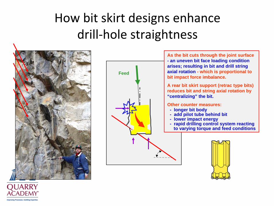
How bit skirt designs enhance drill‐hole straightness
�
Feed
As the bit cuts through the joint surface - an uneven bit face loading condition arises; resulting in bit and drill string axial rotation - which is proportional to bit impact force imbalance.
A rear bit skirt support (retrac type bits) reduces bit and string axial rotation by “centralizing” the bit.
Other counter measures:- longer bit body- add pilot tube behind bit- lower impact energy- rapid drilling control system reacting
to varying torque and feed conditions
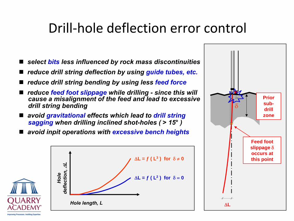
Drill‐hole deflection error control
Hol
e de
flect
ion,
ΔL
Hole length, L
ΔL = ƒ ( L3 ) for δ ≠ 0
ΔL = ƒ ( L2 ) for δ = 0
δ
Feed foot slippage δ
occurs at this point
ΔL
Prior sub- drill zone
select bits less influenced by rock mass discontinuitiesreduce drill string deflection by using guide tubes, etc.reduce drill string bending by using less feed forcereduce feed foot slippage while drilling - since this willcause a misalignment of the feed and lead to excessivedrill string bendingavoid gravitational effects which lead to drill stringsagging when drilling inclined shot-holes ( > 15° )avoid inpit operations with excessive bench heights
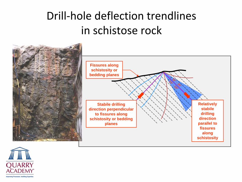
Drill‐hole deflection trendlines in schistose rock
15° - 20°
15° - 20°
Stabile drilling direction perpendicular
to fissures along schistosity or bedding
planes
Relatively stabile drilling
direction parallel to fissures
along schistosity
Fissures along schistosity or
bedding planes
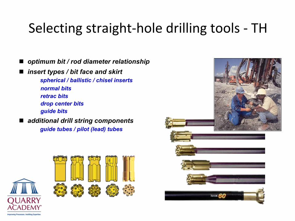
Selecting straight‐hole drilling tools ‐
TH
optimum bit / rod diameter relationshipinsert types / bit face and skirt
� spherical / ballistic / chisel inserts� normal bits � retrac bits� drop center bits� guide bits
additional drill string components� guide tubes / pilot (lead) tubes
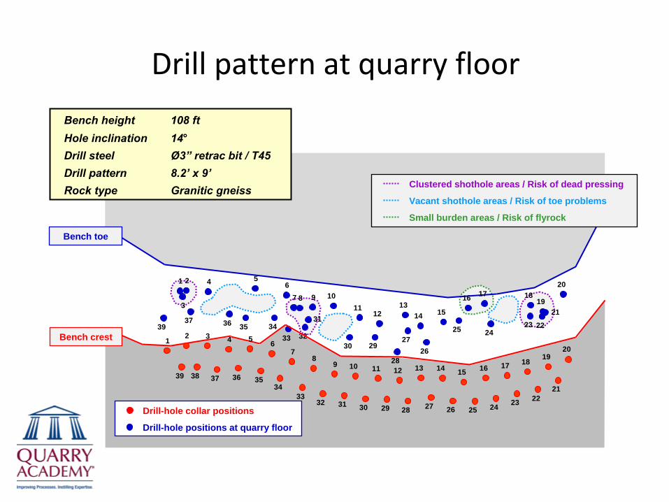
Drill pattern at quarry floor
1 2
37
3
4 56
39 36 35 3433 32
31
7 8 9 1011
12
30 29
28
2726
1314 15
25 24
16 17 18
23
20
22
2119
1 2
38
3 4 5 6
39 36 3534
3332 31
78
9
3710 11 12 13 14 15 16
30 29 28 27 26 25 24 23 2221
20
17 18 19
Bench toe
Bench crest
Drill-hole collar positions
Drill-hole positions at quarry floor
Clustered shothole areas / Risk of dead pressing
Vacant shothole areas / Risk of toe problems
Small burden areas / Risk of flyrock
Bench height
108 ftHole inclination
14°Drill steel
Ø3”
retrac bit / T45Drill pattern
8.2’
x 9’Rock type
Granitic gneiss
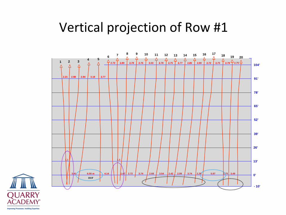
Vertical projection of Row #1
104’
91’
78’
65’
52’
39’
26’
13’
0’
- 10’
2019181716151413121110987654321 2.75 2.752.792.722.902.852.772.752.783.032.752.782.902.72
2.773.182.842.882.21
3.491.755.972.203.742.992.423.542.683.742.721.674.146.08 m
19.9’
3.41
1.1 1.1
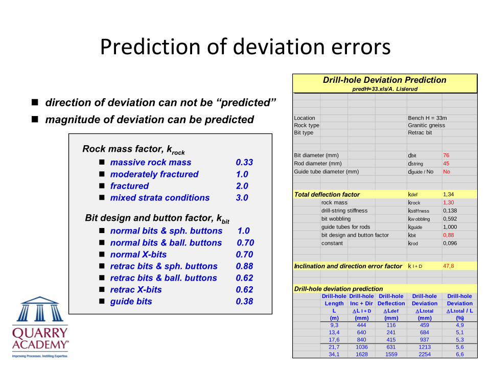
Prediction of deviation errorsDrill-hole Deviation Prediction
predH=33.xls/A. Lislerud
Location Bench H = 33mRock type Granitic gneissBit type Retrac bit
Bit diameter (mm) dbit 76Rod diameter (mm) dstring 45Guide tube diameter (mm) dguide / No No
Total deflection factor kdef 1,34rock mass krock 1,30drill-string stiffness kstiffness 0,138bit wobbling kw obbling 0,592guide tubes for rods kguide 1,000bit design and button factor kbit 0,88constant krod 0,096
Inclination and direction error factor k I + D 47,8
Drill-hole deviation predictionDrill-hole Drill-hole Drill-hole Drill-hole Drill-holeLength Inc + Dir Deflection Deviation Deviation
L ΔL I + D ΔLdef ΔLtotal ΔLtotal / L(m) (mm) (mm) (mm) (%)9,3 444 116 459 4,9
13,4 640 241 684 5,117,6 840 415 937 5,321,7 1036 631 1213 5,634,1 1628 1559 2254 6,6
direction of deviation can not be “predicted”magnitude of deviation can be predicted
Rock mass factor, krockmassive rock mass 0.33moderately fractured 1.0fractured 2.0mixed strata conditions 3.0
Bit design and button factor, kbitnormal bits & sph. buttons 1.0normal bits & ball. buttons 0.70normal X-bits 0.70retrac bits & sph. buttons 0.88retrac bits & ball. buttons 0.62retrac X-bits 0.62guide bits 0.38

Factors affecting drill‐hole deviation
■
drill string startup alignment■
bit will follow a joint if at sharp angle to bit path■
drill string stiffness and “tube”
steering behind bit■
deviation increases with impact energy■
button shape, bit face and bit body design■
drilling with dull buttons (worn bits)■
bit diameter checks when regrinding■
feed foot slippage while drilling■
removal or controlled drilling through prior sub-drill zone■
drilling control systems, i.e.-
applied feed, torque and percussion dynamics■
operator motivation!

Mina Alumbrera ‐ Double bench presplitting

Mina Alumbrera ‐ Pitwall scanlines

Wall control drilling ‐ Macon Quarry, GA
DP1500 - Ø87/3½” Tubes - 80’ Bench - Ø140/5½” Presplit Sorted hole "number"
0,0
0,5
1,0
1,5
2,0
2,5
3,0
1 3 5 7 9 11 13 15 17 19 21
Presplit
ProductionH
ole
devi
atio
n fr
om c
olla
r lo
catio
n, Δ
L (f
t)
Excessive deviation due to feed foot slippage

Wall control drilling ‐ Macon Quarry, GA
ΔL % Δx = Δy α β
Max error
1.48 ft 1.8
1.05 ft ( ≈
2d )
0.75°
12.0°Median error 0.49 ft 0.6 0.36 ft ( ≈ d ) 0.25° 4.2°
Δx = error parallel to wall -
lesser importanceα
= atan Δx / H
Δy = error perpendicular to wall is of greaterimportance to extent of blast damagein backwalls
β
= atan Δy / S
Δx
ΔL = ( Δx2
+ Δy2
)1/2
Δy
H
α
S
β

Thank You

Workshop ?
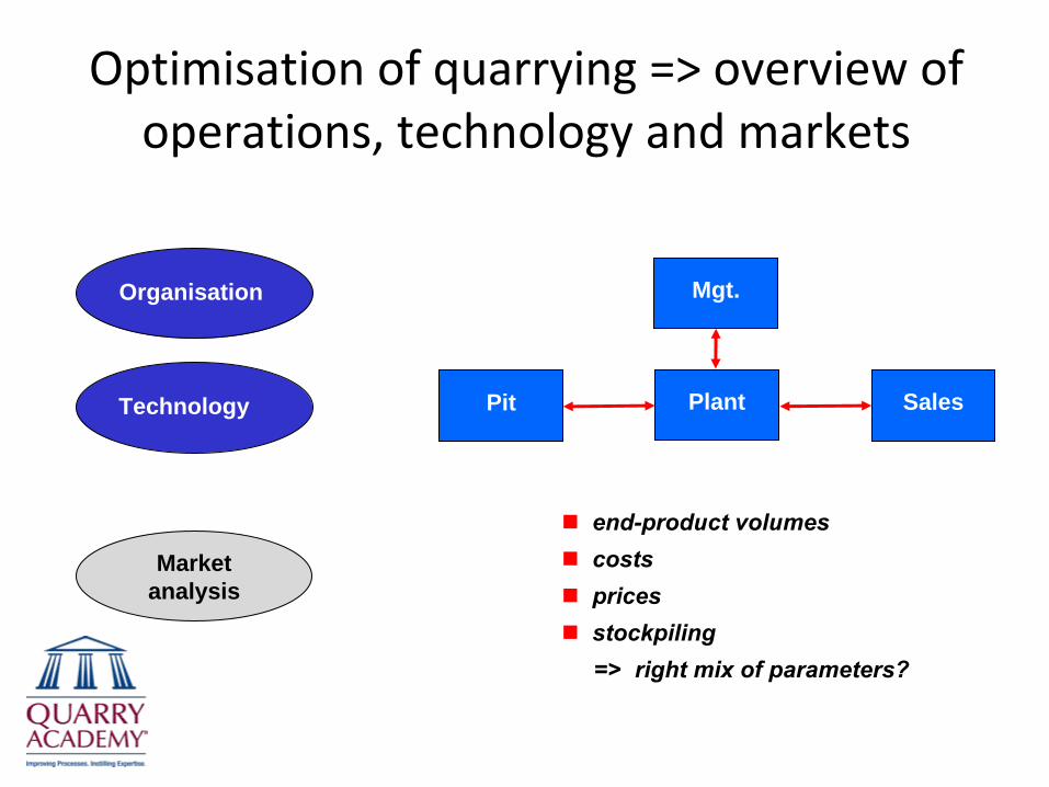
Optimisation of quarrying => overview of operations, technology and markets
end-product volumescostspricesstockpiling=> right mix of parameters?
Mgt.
Plant SalesPit
Organisation
Technology
Market analysis
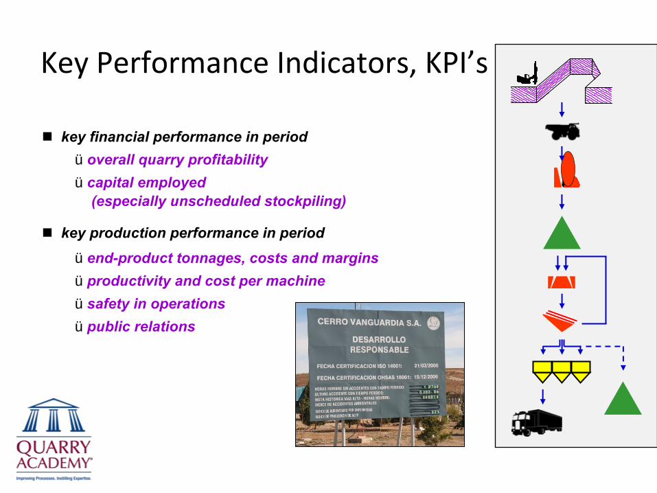
Key Performance Indicators, KPI’s
key financial performance in periodü overall quarry profitabilityü capital employed
(especially unscheduled stockpiling)
key production performance in periodü end-product tonnages, costs and marginsü productivity and cost per machineü safety in operationsü public relations

Occupational health and safety
work related accidents for:� mobile equipment� hazardeous work areas
emissions controlnoise controldust controlfly rock / charging / straight-hole drillingfalling rocks / wall control
⇒ safety is linked as much to equipmentas it is to attitudes
⇒ health, safety and environmentalissues are everyone’s concern
⇒ the ultimate safety target is zero harm –
notjust a mimimum occurrence of accidents
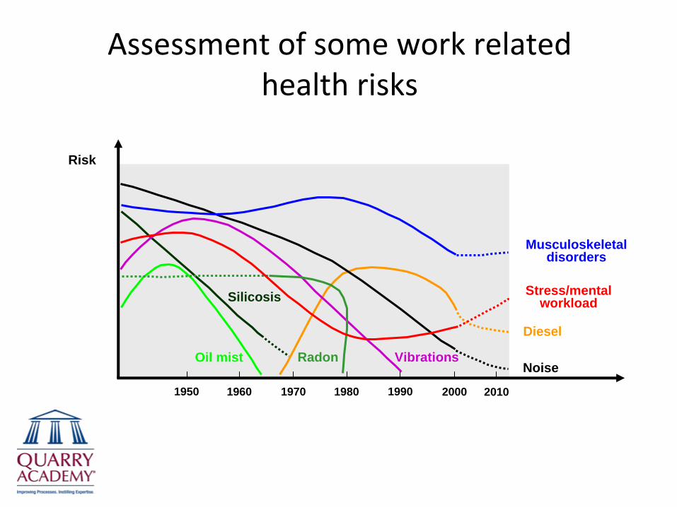
Assessment of some work related health risks
RadonNoise
Oil mist Vibrations
Diesel
Silicosis Stress/mental workload
Musculoskeletal disorders
1950 1960 1970 1980 1990 2000 2010
Risk
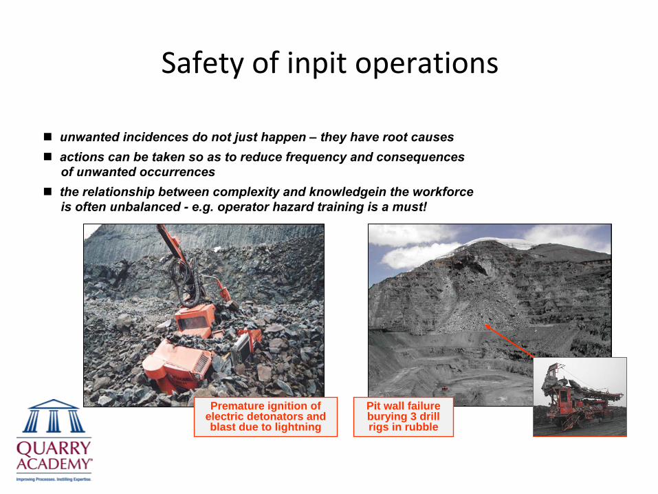
Safety of inpit operations
unwanted incidences do not just happen – they have root causesactions can be taken so as to reduce frequency and consequences of unwanted occurrencesthe relationship between complexity and knowledgein the workforce is often unbalanced -
e.g. operator hazard training is a must!
Premature ignition of electric detonators and blast due to lightning
Pit wall failure burying 3 drill rigs in rubble
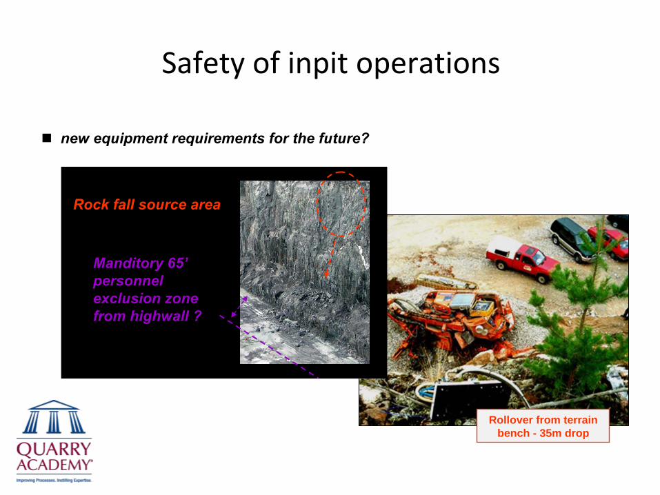
Safety of inpit operations
new equipment requirements for the future?
Rollover from terrain bench - 35m drop
Rock fall source area
Manditory 65’
personnel exclusion zone from highwall ?
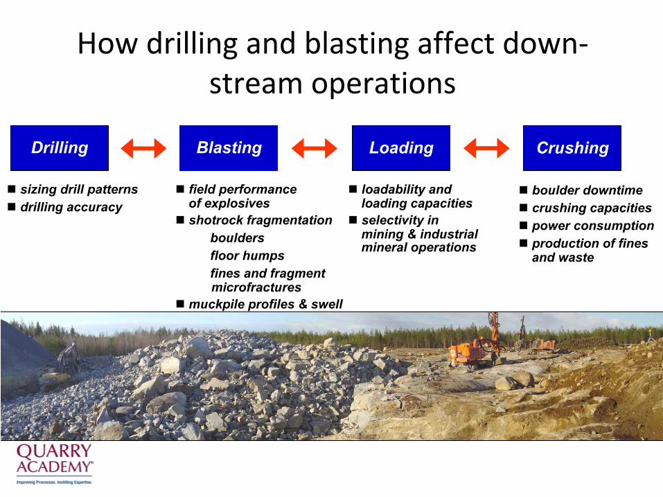
How drilling and blasting affect down‐ stream operations
sizing drill patternsdrilling accuracy
boulder downtimecrushing capacitiespower consumptionproduction of finesand waste
field performanceof explosivesshotrock fragmentation� boulders� floor humps� fines and fragment
microfracturesmuckpile profiles & swell
loadability andloading capacitiesselectivity inmining & industrialmineral operations
Drilling Loading CrushingBlasting
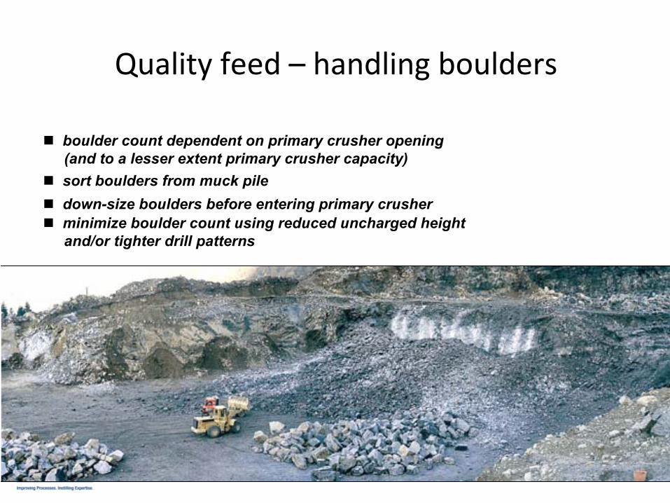
Quality feed –
handling boulders
boulder count dependent on primary crusher opening(and to a lesser extent primary crusher capacity) sort boulders from muck piledown-size boulders before entering primary crusherminimize boulder count using reduced uncharged heightand/or tighter drill patterns
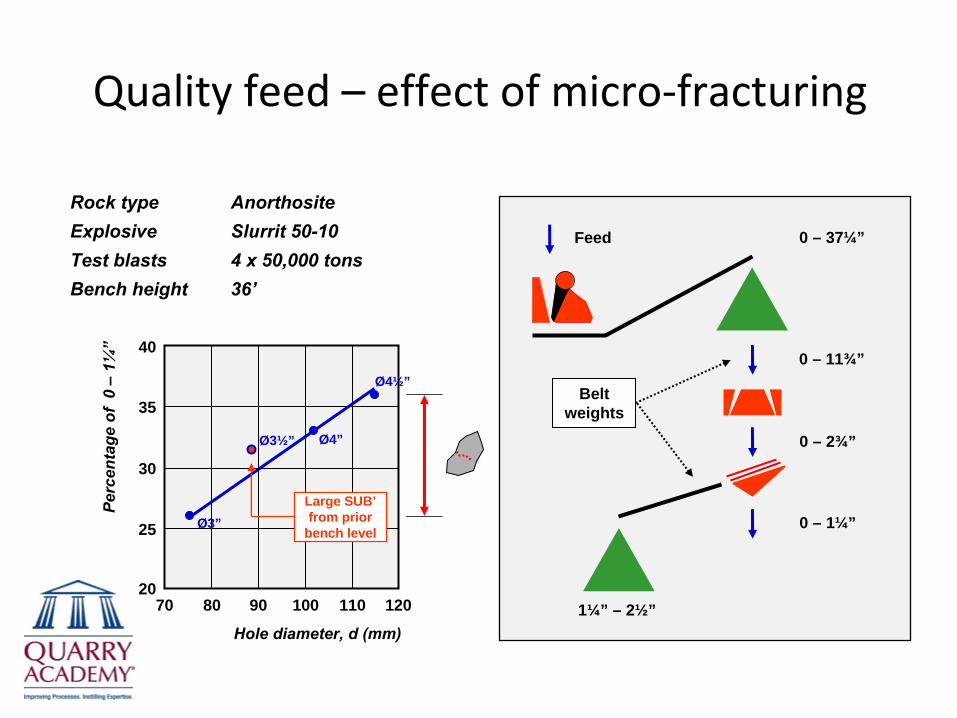
Quality feed –
effect of micro‐fracturing
Rock type
AnorthositeExplosive
Slurrit 50-10Test blasts
4 x 50,000 tonsBench height
36’
70
Hole diameter, d (mm)
80 90 110100 120
35
30
25
20
40
Perc
enta
ge o
f 0
–1¼
”
Ø3”
Ø3½” Ø4”
Ø4½”
Large SUB’ from prior
bench level
0 – 11¾”
0 – 1¼”
Belt weights
Feed
0 – 2¾”
1¼” – 2½”
0 – 37¼”
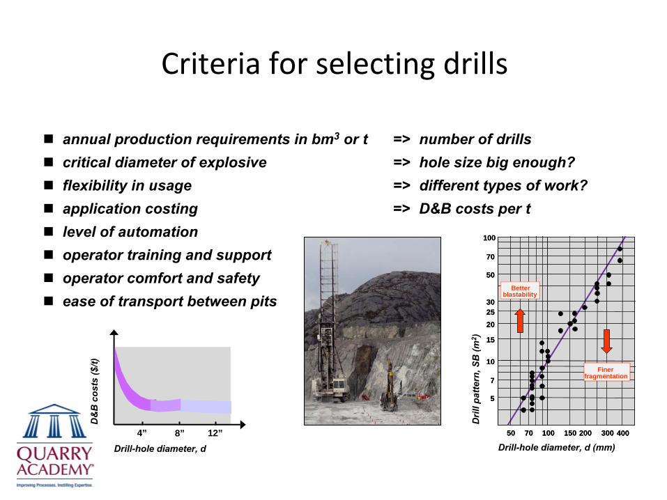
Criteria for selecting drills
annual production requirements in bm3 or t => number of drillscritical diameter of explosive => hole size big enough?flexibility in usage => different types of work?application costing => D&B costs per tlevel of automationoperator training and supportoperator comfort and safetyease of transport between pits
50 100 150 20070 300 400
10
7
5
70
15
2025
50
30
Dril
l pat
tern
, SB
(m2 )
Better blastability
Finer fragmentation
100
50 100 150 20070 300 400
10
7
5
70
15
2025
50
30
Drill-hole diameter, d (mm)
Better blastability
Finer fragmentation
100
Drill-hole diameter, d4” 8” 12”
D&
B c
osts
($/t)
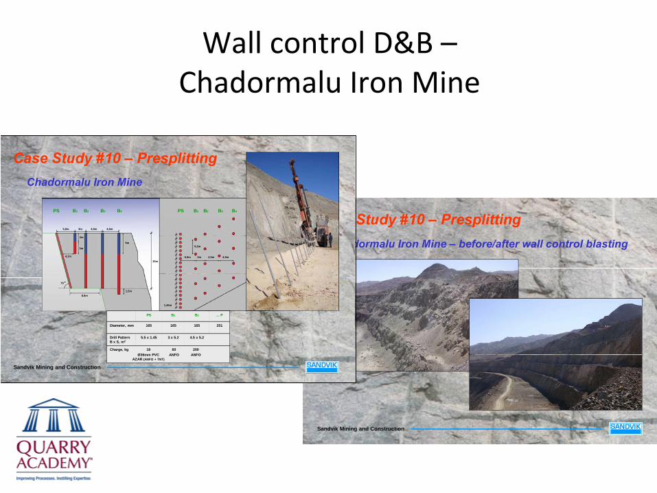
Sandvik Mining and Construction
Case Study #10 – PresplittingChadormalu Iron Mine – before/after wall control blasting
Sandvik Mining and Construction
Case Study #10 – PresplittingChadormalu Iron Mine
15m
PS B1 B2 B3 B4
5,5m 3m 4,5m
4,1m
1,5m8,5m
2m
75 o
4,5m
3m
5m
PS B1 B2 B3 B4 B5
5,5m
5,2m
3m 4,5m 4,5m
1,45m
200ANFO
60ANFO
Charge, kg
4.5 x 5.23 x 5.25.5 x 1.45Drill Pattern B x S, m2
251165165165Diameter, mm
... PB2B1PS
18Ø36mm PVC
AZAR (ANFO + TNT)
Wall control D&B – Chadormalu Iron Mine

Thank You

www.quarryacademy.com


