Page 1
ARTICLE IN PRESS
www.elsevier.com/locate/sedgeo
DTD 5
Sedimentary Geology x
Carbonate deposition and hydrocarbon reservoir development
at the Precambrian–Cambrian boundary:
The Ara Group in South Oman
Stefan Schroder a,b,*, John P. Grotzinger b, Joachim E. Amthor c, Albert Matter a
a University of Bern, Institute of Geological Sciences, Baltzerstrasse 1, CH-3012 Bern, Switzerlandb Massachusetts Institute of Technology, Department of Earth, Atmospheric and Planetary Sciences, Cambridge, MA 02139, USA
c Petroleum Development Oman, P.O. Box 81, Muscat, PC 113, Sultanate of Oman
Received 27 October 2004; received in revised form 13 June 2005; accepted 14 July 2005
Abstract
The Ediacaran–Early Cambrian Ara Group in the South Oman Salt Basin consists of six evaporite–carbonate cycles (A0/A1
to A6) that record tectono-eustatic sea-level changes. The A4 cycle developed at the Precambrian–Cambrian boundary (~542
Ma). It forms a single depositional sequence with evaporites deposited in a lowstand systems tract (LST). Overlying carbonates
represent an open-marine shallowing-upward ramp succession that developed in transgressive (TST) and highstand systems
tracts (HST). The low-energy carbonate ramp occupied a relatively protected site between a large shelf and an exposed
paleogeographical high.
The TST facies include sulfates, evaporite–carbonate laminites, and organic-rich carbonate laminites that record initial
flooding, deepening of the basin, and establishment of an outer ramp depositional environment. Carbonate sediment flux was
low and the environment was partly subject to cyclically elevated salinity. Subsequent HST facies comprise mostly fine-grained
clastic carbonates and stromatolites that formed in middle and inner ramp settings. These facies show evidence of shoaling and
establishment of a carbonate factory that probably operated over most of the middle and inner ramp. Sediment was redistributed
in suspension, by muddy turbidity currents, muddy debris flows, storm and shallow-water currents. During the late HST,
carbonate facies were affected by elevated salinity and recorded the gradual transition to the overlying LST evaporite unit. A
combination of strong tectonic subsidence and transient flooding caused significant shallow-water evaporite deposition to occur
not only down dip, but also on top of the former carbonate platform, where several hundreds of meters of evaporites
accumulated.
The transgressive carbonate laminites are the main reservoir facies and thus represent a relatively unusual reservoir unit. The
presence of organic material and the relative scarcity of carbonate mud influenced diagenesis and reservoir properties.
Distribution of organic material and carbonate mud can be linked to specific environmental conditions (low physical and
biogenic disturbance of sediment and stratified water mass) and the sequence stratigraphic position (low flux of fine-grained
0037-0738/$ - s
doi:10.1016/j.se
* Correspondi
E-mail addre
x (2005) xxx–xxx
ee front matter D 2005 Elsevier B.V. All rights reserved.
dgeo.2005.07.002
ng author. University of Johannesburg, Auckland Park 2006, Johannesburg, South Africa. Fax: +27 11 4892309.
ss: [email protected] (S. Schroder).
SEDGEO-03487; No of Pages 28
Page 2
ARTICLE IN PRESS
S. Schroder et al. / Sedimentary Geology xx (2005) xxx–xxx2
carbonate during TST). In contrast, diagenetic evaporite formation has largely degraded reservoir quality in porous shallow-
water facies near the top of the A4C.
D 2005 Elsevier B.V. All rights reserved.
Keywords: Ediacaran; Cambrian; Oman; Carbonate ramps; Sequence stratigraphy; Reservoir rocks
1. Introduction
Growing research has refined the picture of archi-
tecture, facies dynamics, biostratigraphy and chemos-
tratigraphy of Precambrian carbonate platforms,
placing them within the context of environmental
and biological evolution (Grotzinger, 1989; Grotzin-
ger and James, 2000, and references therein). Neopro-
terozoic and Ediacaran carbonates in particular are
now well understood, with a level of detail that is
similar to Phanerozoic platforms (e.g., Pelechaty et
al., 1996; Turner et al., 1997; Adams et al., 2004;
DiBenedetto and Grotzinger, in press; Grotzinger et
al., in press). These rocks record significant environ-
mental and biological changes and they include
Salalah
Qara Arch
GK
present-daysalt limit
AnoxicBasin
Ghudun-Khasfah
High
CentralOman High
NorthernPlatformDomain
50 km
Easter
n Flan
kSouthernPlatformDomain
study area(Fig. 3A)
Fig. 1. Structural and paleogeographic setting of the study area. Large m
surrounding structural highs. Inset map illustrates paleogeography of the S
area is marked by black box (see Fig. 3A) (modified after Loosveld et al
thrombolite buildups and the first skeletal metazoans
that added to the complexity of carbonate facies and
sediment production (Grotzinger and James, 2000;
Hofmann and Mountjoy, 2001; Watters and Grotzin-
ger, 2001; Wood et al., 2002; Grotzinger et al., in
press). These elements, unknown from older Precam-
brian carbonates, represent precursors of younger car-
bonates that are strongly influenced by calcifying
metazoans. However, to understand the impact of
this evolutionary event on facies distributions in the
Early Cambrian, it is critically important to establish a
baseline of variability in carbonates of latest Neopro-
terozoic (Ediacaran) age.
The Ara Group in the subsurface of the South
Oman Salt Basin (SOSB) provides such an oppor-
Iran
SaudiArabia
500 km100 km N
Muscat
Huqf-H
aush
i
Axis
Paleo- to Mesozoic
Basement
Huqf
Arabian Sea
Sout
h O
man
Sal
t Bas
inG
haba
Sal
t Bas
in
Ophiolite andrelated nappes
Oman Mountains
Fahud Salt
Basin
hudun-hasfahHigh
ap shows overview of the interior Oman sedimentary basins with
outh Oman Salt Basin during the A4 cycle of the Ara Group. Study
., 1996).
Page 3
ARTICLE IN PRESS
S. Schroder et al. / Sedimentary Geology xx (2005) xxx–xxx 3
tunity (Fig. 1). The base of the carbonate platform
studied here coincides with the Precambrian–Cam-
brian boundary in Oman (Fig. 2; Amthor et al.,
2003). Recent studies of the Ara Group have
demonstrated significant environmental changes
leading to a negative carbon isotope excursion
A
A
A
A
A
A
A
A
A
A0
Abu
Mah
ara
Naf
unA
ra
Buah
Shuram
Khufai
Cam
bria
nE
diac
aran
"Cry
ogen
ian"
Basement
ap50
GhadirManqil
MasirahBay
Peri
od
Gro
up
Form
atio
n
Lith
olog
y
Birba
"U"
Al Noor
Dhaha-ban
Supe
rgro
upH
uqf
Lithology key:
Dolostone
Evaporites
Limestone
Sandstone
Fig. 2. Generalized stratigraphy of the Huqf Supergroup in the South Oman S
cycle contains an evaporitic unit (e.g., A4E) and a carbonate unit (e.g., A4
readability. Zircons in volcanic tuffs of the Ara Group yielded ages of 542
fossils support an Ediacaran–Cambrian age of the Ara Group (adapted from
(Fig. 2) and the extinction of early calcified metazo-
ans (Amthor et al., 2003). Thus, the Ara Group can
provide insights into how these environmental
changes influenced platform architecture, deposi-
tional processes and reservoir development across
the Precambrian–Cambrian boundary. The studied
6
5C
5E
4C
4E
3C
3E
2C
2E
-A1
prox.0 m
Ara
Cyc
les
U-P
b ag
es
Bio
stra
t-ig
raph
y
Shale
542.0± 0.3 Ma
542.6± 0.3 Ma
Clo
udin
aN
amac
alat
hus
δ13C[‰ PDB]
-10 +100
alt Basin. The studied interval is highlighted in grey. Each Ara Group
C). Note that carbonate unit thicknesses have been exaggerated for
.0F0.3 Ma, and 542.6F0.3 Ma, respectively. Carbon isotopes and
Burns and Matter, 1993; Loosveld et al., 1996; Amthor et al., 2003).
Page 4
ARTICLE IN PRESS
S. Schroder et al. / Sedimentary Geology xx (2005) xxx–xxx4
platform contains unusual oil reservoirs in deep-
water, laminated, organic-rich carbonates sealed by
evaporites (Mattes and Conway Morris, 1990; Grot-
zinger and Amthor, 2002). This study uses explora-
tion drill cores to examine the spatial relationships
between the different lithofacies and to derive a
depositional, diagenetic and sequence stratigraphic
model for the platform and the reservoir facies.
The discussion emphasizes platform architecture,
constraints on reservoir development, and implica-
tions for the sequence stratigraphy of the carbonate–
evaporite transition.
2. Geological setting
The interior of Oman contains sedimentary
basins that represent a major hydrocarbon province
(Fig. 1; Loosveld et al., 1996). The basins devel-
oped on Neoproterozoic crystalline basement. Neo-
proterozoic to Early Cambrian strata of the Huqf
Supergroup fill the lower parts of these basins (Fig.
2; Gorin et al., 1982; Mattes and Conway Morris,
1990; Loosveld et al., 1996). The age of the Ara
Group, the main exploration target in the SOSB, is
constrained by absolute U–Pb ages, carbon isotope
stratigraphy, and paleontology (Fig. 2; Amthor et
al., 2003).
The Ara Group contains six tectono-eustatic eva-
porite–carbonate cycles (A0/A1–A6); siliciclastic
deposits occur at the top of the Ara Group (Fig.
2; Mattes and Conway Morris, 1990). The lower
unit of each cycle is formed by evaporites that
precipitated during basin restriction (e.g., unit
A4E; Fig. 2). Evaporites are up to several hundred
meters thick and commonly contain the characteris-
tic succession anhydrite–halite–anhydrite (Schroder
et al., 2003). Overlying carbonates are between 50
and 150 m thick (e.g., unit A4C; Fig. 2). They
represent platform carbonates deposited under con-
Fig. 3. (A) Detailed paleogeography of the Birba carbonate platform during
extent of the Birba platform, based on seismic and well data. It was proba
are available for the transition zone (hatching). The western margin of the
Available well data for the Birba platform. The shaded section represents kn
in the deep basin. Carbon isotope data were available only for wells BB-4 a
previously unpublished data). (C) Conceptual cross-section over the platf
major paleogeographic features. The shaded area defines known occurren
ditions of normal marine salinity (Mattes and Con-
way Morris, 1990). In sequence stratigraphic terms,
Ara Group evaporite–carbonate cycles usually con-
tain more than one depositional sequence. However,
the A4 cycle of this study represents a single
depositional sequence with evaporite deposition in
the LST, and deposition of evaporites and carbo-
nates in TST and HST.
The A4 cycle contains the Precambrian–Cambrian
boundary, constrained by a volcanic tuff dated at
542.0F0.3 Ma (Fig. 2; Amthor et al., 2003). During
deposition of the A4 cycle, the SOSB was divided
into three paleogeographic areas (Fig. 1). The north-
ern and southern carbonate platform domains flanked
an anoxic basin probably several hundred meters
deep. Well data suggest that the southern platform
domain represented a broad shelf with localized car-
bonate accumulations that formed isolated platforms
of A1–A5 age. The Birba platform nucleated close to
the eastern edge of this shelf, and contains a V80-m-
thick A4 carbonate unit (A4C; Fig. 3A). Positive
identification of the A4C relies on seismic data, lithos-
tratigraphy, a distinctive gamma-ray spike that marks
the dated tuff, and negative inorganic carbon isotopes
(Fig. 3B; Amthor et al., 2003, 2005). These data
suggest that the A4C thins below seismic resolution
west of the Birba platform, where the A4 cycle is
entirely evaporitic (Fig. 3B). Due to high subsidence
east of the shelf edge, A4C-equivalent shales and
cherts were deposited in the adjacent deep basin
(Fig. 3B).
Wells through the eastern edge of the intra-plat-
form shelf contain stacked carbonates without evapor-
ites, and facies include thrombolite buildups, shallow-
water facies and karst (Fig. 3B; Pope et al., 2000;
Schroder, 2000). The gamma-ray spike and the carbon
isotope anomaly are absent, and carbonates are over-
lain by evaporites of the A5 cycle (Fig. 3B). Conse-
quently, these carbonates are older than the A4 cycle.
The shelf edge may have been exposed during deposi-
deposition of the A4 carbonate. The shaded area defines the known
bly attached to the shelf edge of the intra-platform shelf, but no data
central anoxic basin may have been constructional or structural. (B)
own A4 carbonate. Cherty shales are equivalent to the A4 carbonate
nd SB-1 and are given inxPDB (data from Amthor et al., 2003 and
orm to illustrate overall platform geometry and the position of the
ce of the A4 carbonate.
Page 5
ARTICLE IN PRESS
S. Schroder et al. / Sedimentary Geology xx (2005) xxx–xxx 5
tion of the A4C, or any deposited A4C was subse-
quently removed by erosion. Given the karstified
carbonates, the first interpretation is preferred here,
W
ShelfKAB-1
Birba PlatformBB-4
S
B
WC
A
Shelf
UnknownTransition
BB-5
KAB-1
BBN-1BBN-2
BB-3
BB-2BB-7
BB-6
BirbaPlatform
Fig. 3B
Fig. 12
A4
A3
A5
gamma-ray[api]
0 100 Lithology
Stratigraphy
gamma-ray[api]
0 100 Lithology
δ 13C
Stratigraphy
A3
A5
gamma-[api]
0 10-5 0 +5
BB-4
Birba PlatformShelf
? A4
A4C
Fig
and the Birba ramp onlapped and was attached to the
paleogeographical high at the shelf edge (Fig. 3C;
Amthor et al., 2005).
100m
E
helf EdgeSB-1
BasinMMNW-7
Anhydrite
Dolostone
Halite
Limestone
wells used inthis study
other welllocations
Shale/Cherty Shale
Key:
E
ExposedShelf Edge
Basin
MMNW-7
10 kmN
pre-
A4?
A5
A4
A6
A3
ray0 Lithology
Stratigraphy
gamma-ray[api]
0 100 Lithology
Stratigraphy
SB-1
δ 13C
-5 0 +5
ExposedShelf Edge Basin
pre-A4
A4. 13
Page 6
ARTICLE IN PRESS
S. Schroder et al. / Sedimentary Geology xx (2005) xxx–xxx6
3. Facies analysis
3.1. Stratigraphic framework and vertical succession
The facies succession of the A4 cycle includes
lowstand evaporites overlain by carbonate ramp
lithofacies
porosityhigh
lithologyunit reservoir
units
c
s
v
lutite
arenite
breccia
bound-
stone
A4C
A5E
A4E
50–1
50 m
evaporites
C
B
A
Fig. 4. Summary log of the A4 carbonate, showing the vertical succession
right. Porosity distribution is given as a proxy for reservoir quality in the
properties), and C (intermediate–good reservoir properties). See text for d
deposits (Mattes and Conway Morris, 1990). Rapid
deepening at the base was followed by shoaling to sea
level (Fig. 4; Mattes and Conway Morris, 1990). The
lithofacies are grouped into outer ramp, middle ramp
and inner ramp facies, evaporite–carbonate transition
and associated facies (Fig. 4 and Table 1). The follow-
dominantlithofacies
rampenvironment
laminated/ross-lamin.dolostone,dolarenite
tromatolite
anhydrite
massive/laminateddolostone
crinklylaminite
flatlaminite
olcanic tuff
anhydrite
halite
subtidal,periodicexposure
shallowsubtidal,frequent
reworkingin
ner
ram
p
middle rampsuspended mud,
mass flowdeposition
outer ramppelagic
deposition
gypsumsalina
halitesalina
gypsumsalina
Lithofacies:
Key:
LF 2
LF 3
LF 4
LF 5
LF 6
LF 7
LF 8
LF 9
LF 10
LF 1
anhydrite
siltstone
dolomite
Lithology:
halite
of lithofacies on the left and the different ramp environments on the
three reservoir units A (good reservoir properties), B (poor reservoir
iscussion.
Page 7
AR
TIC
LE
IN P
RE
SS
(continued on next page)
Table 1
Detailed description of A4 carbonate lithofacies
Lithofacies Occurrence and thickness Sedimentary structures Componen an
microfacie
Remarks
Evaporite–carbonate transition
LF 1 Anhydrite A4 and A5 evaporite units;
sharp contact A4E to A4C,
gradual transition A4C to
A5E via interbedded
anhydrite
Nodular, bedded and
massive anhydrite; upright
palmate nodules after
selenite gypsum; rare
desiccation cracks
Micritic d omi between
nodules, l ina chevron
dolomite i lus ns
LF 2 Volcanic tuff
Fig. 6
Sharply overlying LF 1 at
base of A4C; up to a few
decimeters thick; top
gradual to LF 3
Faint millimetric lamination
to mottled and streaky;
graded, load casts and
desiccation cracks; skeletal
halite casts with clastic
sediment fill
Sand- and ilt- ed quartz,
feldspar, s tter pyrite,
volcanic z con
(size 50–1 Am and
glauconite (sub ngular
grains; ma ix w th micritic
dolomite, icro rystalline
anhydrite d d ormed
displacive nhy ite
nodules
Outer ramp
LF 3 Flat laminite
Fig. 7A–B
Lowermost carbonate unit
of A4C; thickness 2–3 m;
top gradual to LF 4; near
base centimeter-thick
intercalations of LF 1 with
sharp contacts
Millimetric even
laminated dolo-lutite and
anhydrite (varves) with
slumps, drag folds, kink
bands and small faults;
transition between laminae
gradual or sharp; rare
erosive bases of anhydrite
laminae
(1) Altern ion
dolomite– hyd te. Fine
crystalline uh ral to
anhedral d lom ; small
laths or eq ant locky
anhydrite ryst s (size 10
Am to 10 200 Am), laths
often para l to amination;
anhydrite nte s V50%
No porosity; some
laminae replaced by
quartz and brecciated
(2) All la ina dolomitic.
Finely cry talli anhedral
crystals in ark minae,
medium c stal e euhedral
crystals in ight aminae;
some lam ae ith peloids
(diameter –11 Am)
aligned pa llel
lamination
S.Schroder
etal./Sedimentary
Geologyxx
(2005)xxx–
xxx7
ts
s
ol
am
nc
s
ca
ir
00
,
tr
m
an
a
at
an
, e
o
u
c
�lle
co
m
s
d
ry
l
in
50
ra
d
te
r
io
siz
ed
s
)
)a
i
c
ef
dr
ri
ed
ite
b
al
l
nt
e
ne
la
lin
l
w
0
to
Page 8
AR
TIC
LE
IN P
RE
SS
Table 1 (continued)
Lithofacies Occurrence and thickness Sedimentary structures Components and
microfacies
Remarks
Outer ramp
LF 4 Crinkly laminite
Fig. 7C–D
Thickness ~15 m; top
gradual to LF 5 via
thickening of light laminae
and increasing abundance of
LF 5 interbeds; some
millimeter- to centimeter-
thick interbeds of LF
10FLF 9
Sub-millimetric to
millimetric crinkly
laminated dolomite;
slumping, in-situ
brecciation, small-scale
thrusts
Dark laminae with finely
crystalline dolomite, partly
micritic; slightly clotted
microfabric; laminae rarely
discontinuous, including
lenses of coarser dolomite;
relatively organic-rich
Pinpoint (vuggy)
porosity common near
base of light laminae,
intercrystalline porosity
Dark laminae with flat base
and millimeter-scale
irregularities at top, relief
draped by light laminae;
chips of dark laminae
incorporated in light
laminae
Light laminae with medium
to finely crystalline
dolomite (coarser than in
dark laminae), often normal
graded crystal size,
idiotopic texture
Middle ramp
LF 5 Massive dolostone
Fig. 9A
Basal unit of middle ramp;
top gradual to LF 6; bedsets
several decimeter-thick and
millimeter- to decimeter-
thick interbeds in crinkly
laminites, sharp contacts
Clean structureless
dolostone, rare wispy
lamination; rare erosion
surfaces
Finely to medium
crystalline dolomite,
idiotopic to xenotopic
texture; ?intraclasts
suggested by different
dolomite crystal size and
porosity
Intercrystalline porosity
and few rounded
oversized vugs
LF 6 Laminated dolostone
Fig. 9B
Thickness combined with
LF 5 is ~9 m; centimeter to
decimeter interbeds of LF 9
and LF 10 most common in
well BB-3
Similar to LF 5, but
millimeter- to
centimeter-scale lamination,
even to wavy, often wispy;
rare erosion surfaces
Lamination determined by
graded crystal size, and by
solution seams/stylolites
creating a secondary stylo-
lamination
Intercrystalline porosity
Inner ramp
LF 7 Cross-laminated
dolostone Fig. 9C
Interstratified with massive
(LF 5) and laminated
(LF 6) beds; increase in
abundance up-section
Millimetric ripple-
lamination, planar cross-
lamination, low-angle
trough cross-lamination,
and ?swaley cross-
lamination; rare erosion
surfaces
Microfacies similar to
LF 5 and LF 6
Originally silt- to sand-
sized clastic carbonates
S.Schroder
etal./Sedimentary
Geologyxx
(2005)xxx–
xxx8
Page 9
AR
TIC
LE
IN P
RE
SS
LF 8 Stromatolite
Fig. 10
Top 5–15 m of A4C;
interbes of LF 1 in
transition to A5E; LF 5 and
LF 9 form centimeter-thick
interbeds with well-defined
and erosive contacts
Stratiform, LLH- and SH-
type stromatolites, rare
columnar-tufted
stromatolites; millimeter- to
centimeter-sized domes,
transitional to wavy
laminated mudstones
(LF 6); additional dendritic
and chevron structures,
isopachous and fenestral
stromatolites;
recrystallized? thrombolites
at top of BB-5; desiccation
cracks, scouring surfaces
Stratiform, LLH, SH and
columnar-tufted with
discontinuous uneven
lamination; micritic to
strongly recrystallized
dolomite, replacive
evaporites and evaporite
cements
Intercrystalline and
vuggy porosity
Associated facies
LF 9 Dolarenite
Fig. 11A–C
Distinct millimeter- to
centimeter-thick beds
associated with other
carbonate lithofacies; most
abundant on inner ramp
Massive or wispy
laminated, graded
Sand-sized intraclasts,
partly elongate or irregular
with micritic rim; silt- to
sand-sized peloids, some
sand-sized ooids and
oncoids, rare aggregate
grains; ooids and oncoids
with brickwork-texture,
layers often spalled off;
finely to medium crystalline
dolomite, idiotopic to
xenotopic texture
Primary wackestones
and packstones; oncoids
mostly associated with
stromatolites;
intercrystalline and
intragranular porosity
LF 10 Intraclastic breccia
Fig. 11D
Millimeter- to centimeter-
thick beds associated with
other carbonate lithofacies,
notably LF 4 and LF 6;
most abundant on inner
ramp
Massive Poorly sorted, angular and
flat dolostone clasts in fine
dolomite matrix; clasts
faintly laminated to massive
S.Schroder
etal./Sedimentary
Geologyxx
(2005)xxx–
xxx9
Page 10
ARTICLE IN PRESS
S. Schroder et al. / Sedimentary Geology xx (2005) xxx–xxx10
ing sections describe the vertical facies succession and
the main characteristics of each lithofacies, followed
by an interpretation of depositional processes and
environments.
An irregular, sharp surface separates the A4E from
the overlying basal A4 tuff (LF 2); the surface is used
as a datum for all studied wells (Figs. 4 and 5;
Schroder et al., 2003). Up-section, carbonate content
and degree of lamination increase, and the tuff grades
into flat laminites. Flat and crinkly laminites together
form a uniform outer ramp package without signifi-
cant lateral facies variation in the studied cores (LF 3
and 4; Fig. 5).
Towards the top of the outer ramp succession,
intercalations of massive dolostones become more
abundant (LF 5; Figs. 4 and 5) and produce a gradual
transition to the overlying massive dolostones of the
middle ramp. Further up-section, massive dolostones
gradually pass to laminated dolostones (LF 6; Figs. 4
and 5). Thickness and lithofacies character of massive
and laminated dolostones remain constant between
wells.
The first appearance of cross-laminated dolostones
(LF 7) marks the base of the inner ramp. In contrast to
the underlying environments, the inner ramp exhibits
high variability defined by common alternations of
various lithofacies (Fig. 5). Deposits of the inner ramp
are dominated by laminated and massive dolostones,
but intercalations of cross-laminated dolostones,
dolarenites, and intraclastic breccias gradually
increase up-section (Fig. 5). Very shallow deposits
with indicators of peritidal deposition and exposure
are absent until the topmost 5–15 m of the A4C,
which are dominated by stromatolites (LF 8; Figs. 4
and 5).
Near the top of the A4C, stromatolites are inter-
stratified with beds of nodular mosaic anhydrite (LF
1), and the A4C passes gradually to anhydrite and
ultimately halite of the A5 evaporite unit (Fig. 5;
Schroder et al., 2003).
3.2. Evaporite–carbonate transition
3.2.1. Anhydrite (LF 1)
The anhydrite units both underlying and overlying
the A4C typically contain palmate nodules with lami-
nar chevron inclusions of dolomite (Table 1; Schroder
et al., 2003). These structures are characteristic for
anhydrite pseudomorphs after selenitic gypsum,
which typically forms in shallow gypsum salinas
(Fig. 4; Schreiber and Kinsman, 1975; Schreiber,
1978).
3.2.2. Volcanic tuff (LF 2)
The tuff overlies the A4E anhydrite with a sharp
irregular surface (Figs. 4, 5 and 6A). The rock consists
of siliciclastic and volcaniclastic grains and authigenic
phases (Table 1). Sedimentary structures include rare
desiccation cracks (Fig. 6B) and a few skeletal halite
casts.
Zircons in the tuff have a volcanic origin and
were dated at 542.0F0.3 Ma (Amthor et al.,
2003). The angular nature of all grains indicates
limited aquatic transport. Thus, the rock is inter-
preted as an air fall volcanic tuff with admixed
windblown detrital grains. The irregular base of the
tuff represents corrosion of the underlying evaporites
during flooding of the basin (Figs. 5 and 6A; Schro-
der et al., 2003). Corrosion was accompanied by
collapse of insoluble tuffaceous material into the
depressions and resulted in the chaotic and mottled
fabric, as was observed in modern environments
(Fig. 6A; Lowenstein and Hardie, 1985; Smoot and
Castens-Seidell, 1994). Early diagenetic authigenic
phases further disrupted the sediment and suggest
that salinity in pore waters periodically reached
high levels. Modern analogs for such sediments
form on the surface of sabkhas and playas (e.g.,
saline mudflats), as well as in the shallowest part
of salinas (Smoot and Castens-Seidell, 1994). The
tuff was therefore deposited on a sabkha or playa
surface, whereas in-situ deformation in the saline
environment occurred during or shortly after tuff
deposition.
3.3. Outer ramp facies
3.3.1. Flat laminite (LF 3)
The distinguishing feature of flat laminites is their
millimeter-scale planar and laterally continuous lami-
nation that is reminiscent of varves (Fig. 7A). Lami-
nae are (1) essentially pure finely crystalline dolomite,
or (2) dolomite with 40–50 vol.% of anhydrite (Fig.
7B and Table 1).
Pairs of dolomite–anhydrite, or dolomite–dolomite
laminae define couplets 1–3 mm thick. In each core,
Page 11
AR
TIC
LE
IN P
RE
SS
2.3 km 1 km 3.3 km
2 m
flooding surface= datum
BB-3 BB-2 BB-4
?
?
top:12 mA4C
?
?
A4E
?
top:1 m A4C
base:39 m A4C
?
?
?
?
?
A5E
A4E
?
?
?
?
??
BB-5A5E
A4E
?diageneticbeds
Grain Types:
Sedimentary Structures:planar cross lamination
intraclastspeloidsooidsonkoidsbreccia clasts
ripple cross lamination
gradingerosive basedesiccation cracks
selenite gypsum
rip-up clasts
LLH-stromatolites
SH-stromatolites
tufted stromatolites
fenestral fabricnodular fabric (?diagenetic)
swaley cross laminationwavy-wispy lamination
trough cross lamination
Lithofacies:
LF 2
LF 3
LF 4
LF 5
LF 6
LF 7
LF 8
LF 9
LF 10
LF 1 dolomite crusts
stratiform stromatolites
dendritic structures/isopachous laminatedstromatolites
Stromatolite Types (LF 8)
Fig. 5. Sedimentologic sections of the studied cores. Columns show the lithofacies, whereas symbols refer to additional sedimentary structures and the observed grain types. See Fig.
3A for location of wells.
S.Schroder
etal./Sedimentary
Geologyxx
(2005)xxx–
xxx11
Page 12
ARTICLE IN PRESS
a
a
A B
2 cm 1 cm
Fig. 6. Anhydrite and volcanic tuff. (A) The dashed line marks the sharp irregular contact between anhydrite (a) and the tuff. The volcanic tuff is
massive at its base, while the top shows the characteristic mottled fabric, marked by dark and light streaks. The elongate area of tuff near the
base could represent an injection feature into semi-consolidated sulfate sediment. Well BB-3, depth 9619V. Slabbed section. (B) Detail of the
volcanic tuff with disrupted lamination at the base (black arrow), and a prominent desiccation crack in the center of the photograph. Fine-
sandstone material derived from the overlying lamina fills the crack (white arrow). The upper part of the sample is characterized by a massive to
mottled/nodular fabric. Well BB-5, depth 9999V. Slabbed section.
S. Schroder et al. / Sedimentary Geology xx (2005) xxx–xxx12
dolomite–anhydrite couplets occur in the lower part of
the flat laminite interval. Transitions between these
laminae are commonly gradual and are determined by
variations in the anhydrite contents (Fig. 7A and B).
Up-section, the anhydrite laminae gradually disappear
and they are substituted by organic-rich dolomite
laminae, giving rise to dolomite–dolomite couplets.
Variations in organic matter contents and dolomite
crystal size define the transitions between individual
dolomite laminae (Fig. 7A and B).
The varve-like flat laminites are interpreted to
record dominant rainout of fine carbonate and sulfate
minerals in relatively deeper parts of the platform
(Fig. 4). Previous authors have used finely crystalline
dolomite as an indicator for abundant nucleation sites
in fine precursor sediment (e.g., Murray and Lucia,
1967; Sibley and Gregg, 1987), although additional
factors can complicate this relationship, such as the
ratio between nucleation rate and growth rate (Sibley
and Gregg, 1987), or the observation of multiple
dolomite generations even in fine dolomite (Jones,
2005). It is therefore difficult to estimate grain size
of the original sediment in the present case, but the
detailed preservation of finely laminated fabrics indi-
cate a fine-grained, possibly muddy, precursor.
Gradual variation of anhydrite content between
laminae suggests that sulfate crystals formed in the
water column (probably as gypsum, but now replaced
by anhydrite) and then rained down on the sea floor
forming a crystal cumulate (Fig. 7B), similar to the
Permian Castile Formation (cf. Anderson et al., 1972).
In the Ara Group, sulfate beds were reworked some-
times, transported down slope by gravitationally dri-
ven currents, and deposited as thin layers with an
erosive base. As sulfate deposition was controlled
by salinity, the dolomite–anhydrite couplets represent
a phase when salinity in the water column cyclically
reached sulfate supersaturation. During subsequent
basin evolution, salinity remained largely normal mar-
ine and dolomite–dolomite couplets formed instead.
Shallow-water indicators, such as traction deposits
with shallow-water components, desiccation cracks or
stromatolites, are absent over a thickness of 2–3 m
(Fig. 5). Analogous to other varved deposits, the flat
laminites were deposited in relatively deep water (tens
to hundreds of meters; cf. Anderson et al., 1972).
3.3.2. Crinkly laminite (LF 4)
The millimeter-scale, laterally continuous lamina-
tion in crinkly laminites is very similar to that in flat
laminites (Table 1). Dark organic-rich and light
organic-poor dolomite laminae form couplets (Fig.
7C). The dark laminae are characterized by small
irregularities (bcrinklesQ; Fig. 7D). The light laminae
typically fill the small depressions between the high
points in the dark laminae (Fig. 7D). Dark laminae
Page 13
ARTICLE IN PRESS
A B
C
cryptocrystallinedolomite withorganic film
idiotopicdolomite
xenotopicdolomite
pinpointporosity
g
gs
D
1 cm 1 mm
1 mm
5 mm
Fig. 7. Flat and crinkly laminites. (A) Flat laminites with continuous lamination. Dark laminae are composed of dolomite and anhydrite, whereas
lighter laminae are almost pure dolomite. Contacts can be sharp (s) or gradational (g). Synsedimentary deformation of anhydrite-rich lamina
occurs in the lower half. Well BB-3, depth 9617V. Slabbed section. (B) Photomicrograph of flat laminites showing alternating dolomite (dark)
and anhydrite (light, speckled) laminae. Many anhydrite crystals are elongate flakes (arrows). Note faint grading of anhydrite crystals in upper
half (g) and relatively sharp base of anhydrite-rich lamina at the bottom (dotted lines). Well BB-4, depth 9679V. Cross-polarized light. (C)
Crinkly laminites with organic-rich dolomite (dark) and detrital laminae (light). Arrows point to thin recrystallized zones within detrital laminae
that represent dolomite crusts. Triangles at left show centimetric cycles, each with thick organic-rich laminae at the base and thicker detrital
laminae towards the top. Rectangle indicates area sketched in panel (D). Well BB-3, depth 9606V. Slabbed section. (D) Detailed sketch of the
area outlined by white rectangle in panel (C). Organic-rich laminae commonly have a flat base and an irregular top, while the relief is filled up
by detrital laminae. Note different dolomite crystal textures in detrital laminae, and the pinpoint porosity at the base of individual laminae.
S. Schroder et al. / Sedimentary Geology xx (2005) xxx–xxx 13
usually have low porosity. A combined vuggy pin-
point and intercrystalline pore system in the light
laminae shows high porosity (z10%) and moderate
permeability (V120 mD) (Fig. 8). Aggrading dolo-
mite recrystallization tends to produce a coarser xeno-
topic dolomite texture with a concomitant decrease in
reservoir quality (Schroder, 2000). Some of the coar-
ser dolomites contain greenish fluorescent fluid inclu-
sions that possibly contain immature organic matter or
hydrocarbons (Mattes and Conway Morris, 1990).
Crinkly laminite couplets typically are arranged in
1- to 2-cm-thick cycles (Fig. 7C). At the base of each
cycle, the dark laminae are relatively thick and have a
high relief. Towards the cycle tops, thickness and
relief are reduced progressively while the light lami-
nae become thicker. Dolomite crystals tend to be more
xenotopic than in the thinly laminated crinkly lami-
nites, and they have a dominantly intercrystalline pore
system (Fig. 8). Whereas porosity is still comparable
to that in thinly laminated couplets (V10%), perme-
ability is reduced (V50 mD) (Fig. 8). Towards the top
of the crinkly laminite unit in each core, the propor-
tion of light laminae increases at the expense of
organic laminae. This trend parallels the increase in
distinct beds of massive dolostones (Fig. 9A).
Each couplet of crinkly laminites is interpreted to
reflect accumulation of carbonate with planktonic
organic matter in the dark laminae, alternating with
accumulation of detrital carbonate derived from shal-
lower parts of the platform (Fig. 7C and D). Dolomite
Page 14
ARTICLE IN PRESS
9600
9580
20100
9560
9540
20 40 60 80 1000porosity (%)faciesdepth (') permeability (mD)
oute
r ra
mp
mid
dle
ram
p
organic laminawith finedolomite
dolomite
detr
ital l
ayer
wispyorganic partings
massive and laminateddolostones
organic film
thicker-laminatedcrinkly laminites
thinly-laminatedcrinkly laminites
• thick organic laminae• thin to thick detrital laminae• high porosity (≥ 10%)• moderate permeability (≤ 120 mD)• idiotopic dolomite crystals• vuggy and intercrystalline pore system
• thin organic laminae• thick detrital laminae• reduced porosity (≤ 10%)• reduced permeability (≤ 50 mD)• more xenotopic crystal overgrowths• intercrystalline pore system
• rare thin organic seams• detrital carbonate• variable porosity depends on dolomite petrography: high with idiotopic crystals, low with xenotopic crystals• low permeability (close to 0 mD)• small dolomite crystals• intercrystalline pore system
~ 100 µm
~ 100 µm
~ 100 µm
Fig. 8. Porosity and permeability data for well BB-3; data are derived from core plugs. The corresponding sketches of microfacies in crinkly
laminites and massive dolostones illustrate the variation in reservoir properties. For lithofacies symbols refer to Fig. 5. See text for discussion.
S. Schroder et al. / Sedimentary Geology xx (2005) xxx–xxx14
crystal size and fabric preservation both argue for a
fine-grained precursor (see flat laminites above).
Graded deposits are suggested by the vertical crys-
tal-size variation in some laminae. The positive relief
of several laminae, and in particular those discontin-
uous laminae with lenses of coarser sediment, sug-
gests an additional, but minor development of benthic
microbial mats that formed upright structures and
which were able to trap and bind sediment (e.g.,
Grotzinger and Knoll, 1999). However, there are no
definitive stromatolites—domes and columns of any
size are absent over the entire thickness of crinkly
laminites. Depending on water depth, these mats may
have been photosynthetic or possibly chemoauto-
trophic, such as the mats covering the sub-photic sea
floor in the upwelling zones off Chile, Peru and
Namibia (Gallardo, 1977; Schulz et al., 1999).
The relationship between background sedimenta-
tion and organic matter accumulation can be
explained by one of two possible models: (1) inter-
mittent periods of low to no flux of suspended fine-
grained carbonate allowed the accumulation of
planktonic organic matter and, to a lesser degree,
the establishment of benthic microbial mats, or (2)
constant, but low background flux of suspended fine-
grained carbonate with intermittent planktonic and
benthic blooms. Intermittent and low-volume sedi-
mentation events prevented swamping of the thin
organic-rich laminae by detrital carbonate (cf. Grot-
zinger and Knoll, 1999). Longer term changes in the
relative balance between the two sediment sources
helped control the formation of centimeter-scale
cycles (Fig. 7C).
The lamination character, its lateral persistence
between wells, the absence of any shallow-water
structures like mudcracks or stromatolites, and the
absence of indicators for shallow-water flow like
ripples or lenticular bedding, all argue for deposition
in relatively deep water (tens to hundreds of meters;
Fig. 4). In addition, crinkly laminites occur near the
Page 15
ARTICLE IN PRESS
A B
C D
a
a
a
1 cm 1 cm
1 cm 1 cm
Fig. 9. Fine-grained carbonates. (A) Massive dolostone overlies crinkly laminites with a sharp contact (white arrows). Speckled fabric derives
from variations in dolomite crystal size that might reflect former grains. Well BB-3, depth 9559V. Slabbed section. (B) Laminated dolostone with
pre-compactional anhydrite nodules (a). Dark seams partly consist of solution seams. Well BB-4, depth 9601V. Slabbed section. (C) Laminated
dolostone with faint planar cross-lamination. The irregular surface (arrow, with small stylolite) might represent an erosion surface. Anhydrite
occurs as small clusters of laths or as nodules (a). Well BB-5, depth 9889V. Slabbed section. (D) Massive dolostone intercalated with crinkly
laminites. The marginal zone of the dolostone was recrystallized and transformed into a low-permeability cream-colored dolostone. This
alteration was a synsedimentary to very early diagenetic process related to early lithification, as suggested by the common fracturing of such
beds (white arrow). Well GHF-1, depth 4345 m. Slabbed section. Sample taken from A3C, about 50 km southwest of Birba area.
S. Schroder et al. / Sedimentary Geology xx (2005) xxx–xxx 15
base of a gradual succession of facies with increas-
ing clastic carbonate and shallow-water structures
(Fig. 4). Older Ara Group cycles show a very
similar vertical facies stacking with basal crinkly
laminites, but in these cases, a lateral transition
between crinkly laminites and an equivalent shal-
low-water facies could be demonstrated (Grotzinger
and Amthor, 2002). Periodically, slumping and inci-
pient brecciation occurred, perhaps induced by slope
creep, tectonic activity, gas escape or periodic storm
activity.
3.4. Middle ramp facies
3.4.1. Massive dolostone (LF 5)
Beds commonly are massive, though wispy
organic partings can create faint lamination (Fig. 9A
and Table 1). Whereas massive dolostones are petro-
graphically similar to detrital laminae of underlying
crinkly laminites, dolomite crystals commonly are
smaller in massive dolostone (Fig. 8). Highest poros-
ities are associated with idiotopic dolomite texture and
permeability is generally low (Fig. 8).
Page 16
ARTICLE IN PRESS
S. Schroder et al. / Sedimentary Geology xx (2005) xxx–xxx16
3.4.2. Laminated dolostone (LF 6)
This lithofacies is very similar to massive dolos-
tone, the main difference being the development of a
distinct millimeter- to centimeter-scale lamination
(Fig. 9B). The lamination is created by flat and
wavy organic and stylolitic partings, the latter prob-
ably following a primary organic lamination (Fig.
9B). Graded crystal size may also indicate grading
in the original sediment.
For massive and laminated dolostones, the extent
of dolomitization and fabric destruction prevents firm
identification of grain size in the precursor sediment.
Based on the petrographic characteristics and the
similarity with detrital laminae in crinkly laminites,
it was possibly relatively fine-grained (mudF silt) and
accumulated below fair-weather wave-base. Erosive
surfaces suggest limited reworking and transport. The
position of these two lithofacies in the gradual transi-
tion from an environment with low to intermittent
sedimentation rates (crinkly laminite) to persistent
reworking in relatively shallow water (cross-lami-
nated dolostone) suggests a gradual increase in sedi-
ment export from shallower parts of the ramp. In
summary, massive and laminated dolostones probably
represent a combination of hemipelagic deposition of
suspended carbonate (massive beds, in particular the
interbeds in crinkly laminites), fine-grained turbidites
and/or tempestites (graded beds, some with erosive
bases) and possibly fine-grained debris flows (Fig. 4;
cf. Cook and Mullins, 1983; Pelechaty et al., 1996).
There is however no sedimentary evidence for storms
impinging directly on the sea floor.
3.5. Inner ramp
3.5.1. Cross-laminated dolostone (LF 7)
Cross-lamination includes small-scale ripples, pla-
nar and low-angle trough cross-lamination (Fig. 9C
and Table 1), as well as poorly defined swaley cross-
lamination. Scoured surfaces occur locally at the base
of cross-laminated beds. The microfacies is similar to
that of massive and laminated dolostones.
Traction currents, probably associated with
waves, deposited the cross-laminated dolostones
(cf. Burchette and Wright, 1992). Although poorly
preserved, the swaley cross-lamination suggests the
occurrence of storms (e.g., Southard et al., 1990).
The environment was above fair-weather wave-base
(Fig. 4). Cross-lamination requires a grain size coar-
ser than mud (i.e., N20 Am), and so these rocks are
interpreted to have been silt- to fine sand-sized
carbonate.
3.5.2. Stromatolites (LF 8)
Stromatolite morphologies include (1) stratiform
(Fig. 10A); (2) domal (LLH- and SH-types of Aitken,
1967); (3) columnar-tufted (Fig. 10B); (4) dendritic
and chevron structures (Fig. 10C); and (5) isopachous
(Fig. 10D). Types 1–3 contain common sheet-like
intercalations of dolarenites (LF 9) and massive dolos-
tones (LF 5) (Fig. 5). Desiccation cracks and fenestrae
occur in association with the more columnar-tufted
morphologies. Stromatolites usually are altered; their
microfabric contains micritic to coarsely crystalline
dolomite, abundant evaporite cements and replace-
ments, coarse calcite and minor chert.
The discontinuous lamination of the observed stro-
matolites is consistent with formation by trapping and
binding (Fig. 10A; cf. Black, 1933; Grotzinger and
Knoll, 1999). Stratiform to domal stromatolites com-
monly lack emergence indicators such as desiccation
cracks or fenestral fabrics and, therefore, probably
formed in shallow subtidal environments. Fenestral
and tufted stromatolites contain desiccation cracks,
consistent with formation in very shallow environ-
ments subject to periodic exposure (Figs. 4 and 5; cf.
Hardie and Ginsburg, 1977). The assemblage of stro-
matolites and dolarenites with shallow-water grains
indicates an environment subject to constant agitation.
Evidence for prolonged peritidal deposition is absent
(e.g., there are no peritidal cycles with exposure caps).
The dendritic structures may be explained by one
of two possible models. First, the contained chevron
structures are similar to laminar chevron inclusions
of detrital sediment in selenitic gypsum (Schreiber
and Kinsman, 1975; Schreiber, 1978). This similarity
suggests bacterial breakdown of gypsum, which
resulted in elevated bicarbonate concentrations and
carbonate precipitation (e.g., Decima et al., 1988). In
an alternative model, the dendritic fabrics resemble
tufa structures that are described from recent to
Precambrian tidal flats (e.g., Hardie, 1977; Pope
and Grotzinger, 2000), and from terrestrial environ-
ments (e.g., Chafetz and Folk, 1984; Demicco and
Hardie, 1995). Such tufas commonly form by direct
precipitation in a mineralizing system, possibly
Page 17
ARTICLE IN PRESS
A B
DC
1 cm 1 cm
1 cm1 cm
Fig. 10. Stromatolite types. (A) Stratiform stromatolite (upper half) overlying a massive dolostone. Discontinuous lamination, often with
stylolites, is typical of stromatolites formed by trapping and binding. Lighter specks in the massive dolostone could indicate recrystallized grains
(e.g., arrow, compare Fig. 9A). Dark blebs are anhydrite. Well BB-4, depth 9541V. Slabbed section. (B) Strongly recrystallized tufted
stromatolite with concave-up laminae. Stromatolite incorporates abundant recrystallized grains, mainly ooids and oncoids. Well BB-2, depth
9289V. Slabbed section. (C) Dendritic structures (arrows) with laminar chevron structures. Well BB-5, depth 9844V. Slabbed section. (D) Sample
with isopachous stromatolite at the base. Irregularities are propagated through the complete section. Stromatolite is overlain by strongly
recrystallized and brecciated dolostone. This association is the first evidence for deposition under restricted conditions and elevated salinity (cf.
Pope et al., 2000). Well BB-2, depth 9287V. Slabbed section.
S. Schroder et al. / Sedimentary Geology xx (2005) xxx–xxx 17
mediated by microorganisms (Chafetz and Buc-
zynski, 1992; Grotzinger and Knoll, 1999). In the
A4C, direct precipitation of such carbonate fabrics
would have been coupled to the observed increase in
salinity. Isopachous stromatolites represent a similar
environmental setting (Fig. 10D; see Pope et al.,
2000).
3.6. Associated lithofacies
3.6.1. Dolarenite (LF 9)
Dolarenite beds are graded to massive and contain
silt- to sand-sized grains (Fig. 11A–C and Table 1).
Grain composition varies with stratigraphic position:
Arenites in lower parts of the studied section are
composed mostly of intraclasts and some peloids.
Up-section, peloids and intraclasts are commonly
associated with ooids and oncoids (Fig. 11A and B).
Elongate intraclasts with a micritic rim are common
(Fig. 11C). Porosity ranges up to ~10%, whereas
permeability generally remains below 10 mD.
Based on the presence of grains, dolarenites had
wackestone and packstone precursors. Some could
have been grainstones, where finer material was
winnowed. These rocks were deposited as subtidal
sheets of carbonate arenites that were subject to
repeated reworking by unidirectional and oscillating
currents and waves (Fig. 4). The graded beds may
represent gravitational settling of sediment from tur-
bid storm- or slope-induced flows (cf. Cook and
Page 18
ARTICLE IN PRESS
D
C
2 mm
a
a
a
1 mm
1 mm
A
500 µm
B
Fig. 11. Carbonate grains. (A) Dolarenite bed overlain by massive
dolostone at the top. Grains consist of deformed and hook-shaped
intraclasts, some with internal lamination reminiscent of ooids. Note
common intragranular anhydrite cement (a). Well BB-4, depth
9572.5V. Photomicrograph, plain polarized light. (B) Aggregate
grain with several ooids and intragranular anhydrite cement (a).
Well BB-4, depth 9542V. Photomicrograph, plain polarized light.
(C) Elongate intraclast with irregular outline and micritic rim. Well
BB-4, depth 9542V. Photomicrograph, plain polarized light. (D)
Thin intraclastic breccia sheet within crinkly laminites. Grey: finely
crystalline dolomite of detrital lamina; white: organic lamina recrys-
tallized to cream-colored dolostone; black lines: remains of organic
film. Well BB-5, depth 9941V.
S. Schroder et al. / Sedimentary Geology xx (2005) xxx–xxx18
Mullins, 1983; Aigner, 1985; Aurell et al., 1998).
The vertical trend in grain composition is consistent
with overall shoaling of the platform and an
increased proportion of shallow-water grains. Elon-
gate intraclasts and chips may be derived from the
localized reworking of microbialites and fine-grained
laminated carbonates. Irregular grains with a micritic
rim resulted from boring by endolithic microbes,
although other processes, such as micrite recrystalli-
zation, could have contributed as well (Fig. 11C; cf.
Reid and Macintyre, 2000).
3.6.2. Intraclastic breccia (LF 10)
Breccia beds are massive and contain poorly
sorted, angular and flat dolostone clasts in a fine
dolomite matrix (Fig. 11D). The internal fabric of
clasts is faintly laminated to massive and clast litho-
facies usually matches the surrounding rock. All
stages from in-situ breccias with a fitted fabric, to
transported breccias were observed, but in-situ brec-
ciation is relatively rare.
In upper parts of the A4C, cracked, laminated
dolostones and intraclastic breccias are commonly
associated in centimeter-scale units. Within each
unit, cracking and in-situ brecciation of laminated
dolostones increase up-section, and an intraclastic
breccia caps the unit.
Breccia units may be the result of evaporite
dissolution, exposure, reworking by storms and
waves, or gravity transport, all of which would
have affected at least partially lithified sediments
(cf. Demicco and Hardie, 1995). Evaporite dissolu-
tion collapse is possible only for in-situ breccias
with little matrix, whereas breccias associated with
the deeper water crinkly laminites seem to be
mostly gravity-transported. Breccias of the inner
ramp are related to exposure, storms and/or waves.
In particular, the sequence of beds with up-section
increase of brecciation may represent upward shoal-
ing to the zone of wave or storm reworking. Storm-
and wave-induced cyclic loading can act repeatedly
on partly lithified sediment, with the result that
internal pore pressure may build up and ultimately
cause cracking of the sediment (Suhayda, 1977;
Cowan and James, 1992).
4. Reservoir diagenesis
Porosity and permeability data, derived from neu-
tron and density logs and from core plugs, have been
used to subdivide the A4C into three reservoir units
Page 19
ARTICLE IN PRESS
S. Schroder et al. / Sedimentary Geology xx (2005) xxx–xxx 19
with a remarkably uniform distribution across the
platform (units A–C in Figs. 4 and 12; Mattes and
Conway Morris, 1990; Schroder, 2000). Reservoir
quality is strongly dependent on facies, and the three
reservoir units roughly correlate with inner, middle
and outer ramp facies (Fig. 12). Unit A contains outer
ramp laminites; the porosity ranges from 0.4 to
23.0%, whereas permeability is between 0.01 and
313.0 mD. The crinkly laminites represent the main
flow unit of the A4C. Reservoir unit B encompasses
facies of the middle ramp and part of the inner ramp
(Fig. 12). Porosity varies from 0.7 to 15.5% and
permeability ranges from 0.01 to 80 mD. At its
base, the vertical transition from crinkly laminites to
massive dolostones is characterized by an increase in
detrital, possibly fine-grained carbonate at the expense
A
A
B
B
C
C
BBN-2 BBN-1 BB-5
Lithology FaciesLithologyLithology
Facies
N
datum:
base A4C
top
A4C
datum:
base A4C
top
A4C
slopebreccias
W E
Lithology Facies
BB-2 BB-3
Lithology Facies
?
BB-7
Facies
bioh
erm
? ?
?
porosityhigh
porosityhigh poros
high
porosityhigh
porosityhigh
Fig. 12. North–south (top panel) and west–east (bottom panel) cross-section
of key wells used in the study. Lithology represents a close estimate of
collected during drilling. Facies interpretation is based on core descriptions
were used. These logs provide an image of resistivity distribution. Reserv
of organic material, and a decrease in permeability
that is more pronounced than the parallel decrease in
porosity (Fig. 8). Unit C shows reservoir development
in inner ramp stromatolite and thrombolite buildups
and carbonate arenites. Porosity values are between
0.1 and 21.2%, and permeability varies between 0.01
and 170 mD. Much of the porosity in the A4C is
intercrystalline and associated with relatively fine
(earlier) idiotopic dolomite, whereas coarse late diage-
netic dolomite and calcite replacements and cements
tend to destroy reservoir quality (Mattes and Conway
Morris, 1990; Schroder, 2000). Anhydrite and halite
cements (Fig. 11A and B), pre-compactional anhydrite
nodules (Fig. 9B) and the replacement of carbonate by
evaporites were commonly observed throughout the
A4C. The detrimental effects of evaporites on reser-
20 m
inner rampstromatolite
inner rampcross-lam. dolostone
middle ramp
outer ramp
evaporite-carbonatetransition
BB-6
porosity
BB-4BB-7
Facies:Lithology: Reservoir Units:
Key:
LithologyLithology
FaciesFacies
S
bioh
erm
? ??
?
anhydrite
dolostone
limestone A
B
C
ity porosityhigh
porosityhigh
s of the Birba platform showing lithology, facies and reservoir units
true lithology distribution in the sections and is derived from data
in all wells except BB-7 where FMIk (FormationMicroImager) logs
oir units were calibrated with lithofacies.
Page 20
ARTICLE IN PRESS
S. Schroder et al. / Sedimentary Geology xx (2005) xxx–xxx20
voir quality are best documented by the evaporite
bcapQ at the top of the A4C, where porosity and
permeability drop off rapidly with an increase in
diagenetic evaporites (Fig. 4).
In summary, three key diagenetic controls on reser-
voir quality in the A4C can be identified: generation
and preservation of early idiotopic dolomite, low
permeability in fine-grained carbonates, and the pre-
sence of evaporites. Diagenesis of the A4C will be
discussed briefly to provide a context for these factors.
Pervasive dolomitization was the principal diage-
netic event in the A4C, usually followed by evaporite
cementation and replacement to various extents
(Mattes and Conway Morris, 1990; Schroder, 2000).
Locally, dolomite recrystallized to a coarser mosaic that
destroyed depositional fabrics and further added to
reservoir degradation. The early dolomite phase is
attributed to reflux dolomitization (Mattes and Conway
Morris, 1990; Schroder, 2000). Such a scenario is likely
because dolomites are associated with thick evaporite
deposits, and the abundance of evaporite cements and
replacements testifies to the passage of hypersaline
brines (e.g., Land, 1982). Given the organic-rich nature
of the outer ramp deposits in the A4C, organogenic
dolomitization (e.g., Baker and Kastner, 1981; Slaugh-
ter and Hill, 1991) may have played an additional role,
although the relationship between organic matter and
dolomitization of the A4C is not firmly established.
However, fluorescent fluid inclusions in dolomite crys-
tals of crinkly laminites suggest the presence in the pore
system of early hydrocarbon expulsion products from
the inherent organic material (Mattes and Conway
Morris, 1990; Schroder, 2000). Such fluids could
have delayed diagenesis, preserved early dolomite
and aided in the development of crinkly laminites as
the main flow unit of the A4C (Schroder, 2000).
The relationship between smaller dolomite crystal
size and reduced permeability in massive dolostones
relative to crinkly laminites is consistent with obser-
vations from other basins (Fig. 8; Lucia, 1995).
Although the original grain size cannot be determined
with certainty (see above), it is quite possible that low
permeability in the fine dolomite mirrors conditions in
a fine-grained precursor sediment. As a result, dolo-
mite recrystallization should have been slow, but more
importantly, the massive dolostones act as a low-
permeability barrier to fluid flow at the top of reser-
voir unit A (Fig. 8).
Although the shallow-water facies near the top of
the A4C likely had high initial porosities, these were
partly degraded during diagenesis through precipita-
tion of abundant evaporite cements and replacive
evaporites, in particular in the evaporite bcapQ (Fig.
4; Mattes and Conway Morris, 1990; Schroder, 2000).
In addition, the grainy shallow-water facies occur as
thin beds and are not sufficiently thick to act as
significant flow units.
5. Discussion
5.1. Platform geometry
Key attributes of the A4C are (1) gradual transi-
tions between relatively broad facies belts; (2) mono-
tonous sheets of deeper water facies contrasting with a
greater degree of complexity and lateral heterogeneity
in shallow-water facies; (3) dominantly fine-grained
carbonate with coarser grained facies tending to occur
mostly in the shallowest parts of the succession; and
(4) lack of a discernible break in slope. Very coarse-
grained sediment is conspicuously rare in the transi-
tion zone between the outer and middle to inner ramp
facies belts, which indicates a gentle depositional
profile. Nevertheless, the slope breccias in well
BBN-2 suggest some limited reworking and transport
to deeper parts of the platform, perhaps across a step
in the depositional profile (Fig. 12). Scarcity of grains
points to a low-energy setting for the shallower parts
of the platform. The A4C thus represents a low-
energy muddy carbonate ramp (Fig. 13; see Wilson,
1975; Read, 1985).
The geometry of the Birba ramp is constrained by
its relationship to the broad shelf in the west and the
shelf edge in the east (Fig. 3A). The ramp most likely
onlapped and was attached to the emergent high at the
shelf edge (Fig. 3C). Seismic reflection data show that
the A4C thins out towards the west, and we suggest a
homoclinal ramp sloping away from the shelf edge in
a westerly and/or northwesterly direction (Figs. 3C
and 13).
It is generally difficult to define the internal geo-
metry of thin carbonate ramps (Burchette and Wright,
1992), and the Birba ramp is no exception. The pre-
sent study identified sheet-like units with minimal
thickness variations across the entire Birba area
Page 21
ARTICLE IN PRESS
Fig. 13. Sequence stratigraphic architecture and main surfaces of the A4 evaporite–carbonate sequence. The figure also shows the main
lithofacies, including the crinkly laminite reservoir facies. Wells used in this study are shown in their approximate position on the ramp,
according to distal versus proximal facies affinity. Shaded boxes indicate core coverage.
S. Schroder et al. / Sedimentary Geology xx (2005) xxx–xxx 21
(Figs. 5 and 12). All wells have the tripartite subdivi-
sion of reservoir units that were calibrated with outer,
middle and inner ramp facies. Nevertheless, some
general proximity trends emerge in a picture of the
entire study area (Fig. 12). Thin outer ramp facies in
well BBN-2 include slope breccias and are overlain by
thick successions of middle ramp facies (Fig. 12). A
thrombolitic bioherm was identified in well BB-7.
Other authors have related the growth of such bio-
herms to conditions of sediment-starvation and/or
more available accommodation space (Burchette and
Wright, 1992; Tucker et al., 1993). In the same well,
inner ramp thicknesses are reduced relative to wells
farther east (Fig. 12). These observations suggest that
locations in the west and northwest of the Birba ramp
could have a more distal facies character, consistent
with the assumption that the ramp sloped towards the
west and/or northwest (Figs. 3C and 13).
This setting also explains the low-energy character
of the Birba ramp. The ramp was not facing an open
ocean basin. Winds were dissipated over the large and
relatively shallow shelf, and by the exposed shelf edge
(cf. Burchette and Wright, 1992; Aurell et al., 1998).
5.2. Depositional model and sequence stratigraphy
5.2.1. Lowstand systems tract
The thick evaporite units at the base of individual
Ara cycles represent mostly accommodation minima
within the South Oman Salt Basin (Mattes and Con-
way Morris, 1990; Schroder et al., 2003), and the A4
halite forms the LST of the A4 depositional sequence
(Fig. 14). Lowstand accommodation minima alone
have the potential to provide basin restriction and
surface disconnection from the open ocean that are
required for large-scale evaporite deposition (Tucker,
1991; Sarg, 2001). However, evaporites formed also
during early transgressive and late highstand phases
(see below).
5.2.2. Transgressive systems tract—evaporite–carbo-
nate transition, outer ramp deposition
Two sharp surfaces separate A4 halite and A4
anhydrite, and A4 anhydrite and A4 carbonate, respec-
tively (Figs. 4, 5, 14 and 15A; Schroder et al., 2003).
Older evaporites are corroded along these surfaces and
deep-water A4 carbonates overlie shallow-water sul-
fates (Fig. 6A). The surfaces thus represent flooding
events at the beginning of marine transgression into the
basin (Figs. 14 and 15A; Mattes and Conway Morris,
1990; Schroder et al., 2003). The anhydrite unit
between these surfaces represents an early transgres-
sive systems tract, although the water depth did not yet
increase, as indicated by the preserved shallow-water
selenite structures and desiccation cracks. Due to their
rapid precipitation rates, sulfates were able to fill any
accommodation space created during the early trans-
gression (Schroder et al., 2003).
Page 22
ARTICLE IN PRESS
lithofacieslithologyunit ramp
environment
A4C
A5E
A4E
inner ramp
middle ramp
outer ramp
gypsumsalina
halitesalina
gypsumsalina
sea levelsalinity seq.strat.+- +-
fs
fs
LST
TST
HST
LST
mfs zone
sb zone
Fig. 14. Sequence stratigraphic interpretation of the sedimentary
succession in the A4 carbonate. The evolution of salinity, sea level
and accommodation space is shown on the right. Key surfaces are
indicated (fs—flooding surface, mfs—maximum flooding surface,
sb—sequence boundary). Maximum flooding surface and sequence
boundary are only given as shaded bars, because the exact location
of these surfaces cannot be determined with certainty (see text for
discussion) (modified after Schroder et al., 2003).
S. Schroder et al. / Sedimentary Geology xx (2005) xxx–xxx22
Above the flooding surfaces, continued arid con-
ditions promoted cyclically elevated salinity and the
formation of flat laminites similar to the Permian
Castile evaporites (Figs. 7A and 15A; cf. Anderson
et al., 1972). Crinkly laminites, in contrast, record
deposition under conditions of normal marine salinity
(Fig. 15B). Similar laminites have been described
from other evaporite–carbonate transitions and non-
evaporitic settings (e.g., Davies and Ludlam, 1973;
Knoll et al., 1995; Pope et al., 2000). Requirements
for laminite formation are (1) minimal or absent bio-
logical and physical disturbance of sediments; (2) a
stratified water body with deposition of particles from
surface waters (Davies and Ludlam, 1973). The result-
ing depositional environments were uniform over
large areas, but depositional processes alternated
rhythmically to produce laminites (Davies and
Ludlam, 1973).
The fine-grained carbonate of the A4C outer
ramp could represent a mix of precipitated and
suspended particles, the latter derived from shallow
platform areas. Because there are only a few rela-
tively thin beds of coarser facies, and clasts in these
beds are commonly locally derived, it can be
assumed that the shallower ramp had only limited
influence on outer ramp depositional processes.
Transport distances in these beds may not have
been long.
With slow precipitation and gravitational settling
of sulfate and carbonate minerals as the dominant
sedimentation modes on the outer ramp, deposition
could not keep up with the generation of accommoda-
tion space during flooding (Fig. 14). As a result of the
strong subsidence in the previous evaporitic LST, the
basin represented a relatively deep depression that
was rapidly flooded during transgression, while car-
bonate production lagged behind (Kendall, 1992;
Schroder et al., 2003). Near the top of the crinkly
laminite unit, the onset of significant export of fine-
grained carbonate from shallower parts of the ramp
represents an important change in depositional pro-
cesses. Accommodation space made available during
the previous transgression was more rapidly filled
with sediment derived from proximal parts of the
platform (Figs. 14 and 15B). Because the change is
gradual, a maximum flooding zone is placed close to
the top of crinkly laminites (Fig. 14).
5.2.3. Early highstand systems tract—middle ramp
deposition
The transition between laminites and overlying
fine-grained carbonates is best accommodated in a
prograding ramp model, where distal, finely laminated
rocks show an upward increase in the number of
interbedded massive mudstones and thin debris flow
layers (Fig. 15B). These beds represent increasing
sediment export from shallower parts of the platform.
In this respect, the A4C is similar to the Khatyspyt–
Turkut transition in the terminal Proterozoic section of
the Olenek uplift, Siberia (Knoll et al., 1995; Pele-
chaty et al., 1996).
Middle ramp deposition occurred mostly through
suspension settling during relatively quiet periods,
Page 23
ARTICLE IN PRESS
precipitation of gypsumin surface water; rainout
rainout of suspendedcarbonate mud
sea level
LF 2
LF 3
A4 anhydrite(LF 1)
flooding andcorrosion ofA4 anhydrite
10's to100's of m
high
low
relative sea levelA early TST
rainout of planktonicorganic matter
rainout of suspendedcarbonate mud
10's to100's of m
suspension and transportof carbonate mud
high
low
relative sea level
LF 4
LF 5
B late TST/early HST
distalturbidites +tempestites
high
low
relative sea levelC late HST
LF 5
LF 8
LF 6/7
lateral facies transitionsbetween fine-grained carbonates, coarseclastic carbonates and stromatolites
few m
Key to Fig. 15:
anhydrite
coarse-grained carbonate cross-lamination
stromatolites
selenite sulfate
fine-grained carbonate
organic matter
gypsum crystal flakes
Fig. 15. Stratigraphic and depositional evolution of the A4 carbonate. Panels (A–C) illustrate the major sedimentary processes and facies
deposited. Small sketches at right show evolution of relative sea level. See text for discussion.
S. Schroder et al. / Sedimentary Geology xx (2005) xxx–xxx 23
punctuated by deposition of turbiditic beds and per-
haps distal tempestites (Fig. 15B; cf. Aigner, 1985;
Calvet and Tucker, 1988; Burchette and Wright,
1992). The environment was located below the fair-
weather wave-base. It is, however, impossible to
determine whether the transition between the outer
and middle ramp of the A4C corresponds to storm
wave-base (cf. Burchette and Wright, 1992), because
evidence for direct storm impact on the sea floor is
absent.
Page 24
ARTICLE IN PRESS
S. Schroder et al. / Sedimentary Geology xx (2005) xxx–xxx24
5.2.4. Highstand systems tract—inner ramp
deposition
The first appearance of cross-lamination marks an
important change in the physical processes of sedimen-
tation, from suspension settling to traction. Deposition
occurred in a subtidal environment above fair-weather
wave-base (Fig. 15C). The absence of carbonate sand
shoals suggests wave action was limited in frequency
and/or intensity (cf. Fairchild and Herrington, 1989).
Extensive tidal flats and peritidal cycles are absent, so
tidal processes also had minimal influence.
Studies of other carbonate ramps have suggested
relatively uniform distribution of carbonate produc-
tion over most middle and inner ramp settings, with
no dominant production site as in rimmed shelves
(Wright and Faulkner, 1990; Elrick and Read, 1991;
Burchette and Wright, 1992). This pattern is essential
to maintain a homoclinal ramp profile during shallow-
ing of the ramp (Elrick and Read, 1991). Observations
from the present study are generally consistent with
such a model. The limited occurrence of peritidal
environments or stromatolites in the A4C suggests
that shallow subtidal and peritidal carbonate produc-
tion was not significantly higher than in other, deeper
parts of the ramp (cf. Wright and Faulkner, 1990).
Inner ramp grain types are dominantly of shallow-
water origin. Although micritization of A4C grains
was observed (Fig. 11C), this mechanism could not
have been sufficient to generate the observed amounts
of carbonate mud (Grotzinger, 1989). However, the
production of mud through whitings (Shinn et al.,
1989; Robbins and Blackwelder, 1992) would have
been greatly facilitated by the higher saturation state
of Precambrian seawater for CaCO3 (Grotzinger,
1989; Tucker, 1992; Grotzinger and Kasting, 1993).
In this latter mode, the mud-producing carbonate
factory may have extended over almost the entire
platform, except in the deepest parts where laminites
accumulated under conditions of low sedimentation
rate.
Spatially variable shallow-water currents were
effective agents to cause redistribution and accumula-
tion of dominantly fine-grained carbonate over the
entire inner ramp (cf. Aurell et al., 1998). The hetero-
geneous lithofacies pattern in the shallow areas of the
A4C platform represents a response to reduced rates
of accommodation space creation in a highstand situa-
tion (Figs. 14 and 15C).
5.2.5. Late highstand systems tract—evaporite–carbo-
nate transition
Interstratified anhydrite beds near the top of the A4
carbonate indicate the gradual transition from shal-
low-water carbonate environments to shallow-water
gypsum salinas of the A5 evaporite (Fig. 14). These
deposits could represent platform-wide, but short-
lived events of elevated salinity, although they are
difficult to correlate between wells. Alternatively, sul-
fate deposits may have accumulated locally in salinas
behind irregular stromatolite barriers (cf. Fairchild and
Herrington, 1989).
No regionally significant subaerial exposure sur-
face is observed at the top of the A4C. As a result of
the gradual facies changes, it is difficult to draw a
sequence boundary between the A4 HST and the
subsequent A5 evaporite, and consequently only a
sequence boundary zone was defined (Fig. 14). It
should be emphasized again that the A5 evaporite,
like all Ara Group evaporite units, represents thick
evaporite deposition across the entire SOSB. As such,
it formed during a basin-wide accommodation mini-
mum, which provided the necessary disconnection
from the main water source (Fig. 14; Schroder et al.,
2003). The important observation is that these LST
evaporites blanket the former topographic highs like
the Birba platform. This scenario is in contrast to most
sequence stratigraphic models for large-scale evapor-
ite deposition, which predict exposure of platform
carbonates, while lowstand evaporites precipitate in
the basin (Tucker, 1991).
Increased subsidence on the Birba platform is a
likely mechanism to allow continuous evaporite pre-
cipitation in shallow salinas without significant sub-
aerial exposure (Schroder et al., 2003). At the same
time, tectonic activity caused uplift of barriers (e.g.,
shelf edge east of the Birba platform) and possibly
an additional relative sea-level rise. Characteristic
successions of stromatolites, formed by both trap-
ping/binding and precipitation, and carbonate–eva-
porite laminites can be used as evidence for such a
relative sea-level rise (Pope et al., 2000). For exam-
ple, in well BB-2, tidal flat (?) isopachous stroma-
tolites are overlain by facies of slightly deeper water
(Figs. 5 and 10D), although this succession may
simply relate to shifting tidal flats in the proximal
portion of the platform. In summary, a combination
of increased basin subsidence and possibly transient
Page 25
ARTICLE IN PRESS
S. Schroder et al. / Sedimentary Geology xx (2005) xxx–xxx 25
flooding by high-salinity seawater caused A5 eva-
porite deposition on top of the former carbonate
platform, but without a marked exposure surface
between them.
5.3. Implications for reservoir quality
Sedimentary processes on the Birba ramp,
sequence stratigraphy and diagenesis have important
implications for reservoir characteristics. Reservoir
unit C contains relatively porous shallow-water facies
with good reservoir potential (Fig. 4). However, its
position directly below the A5 evaporite resulted in
degradation of reservoir quality through evaporite
precipitation (Fig. 4).
In reservoir unit A, the distribution of fine-grained
carbonate and organic material had an impact on
reservoir quality of crinkly laminites. Here, organic
material accumulated during a time of reduced flux of
clastic carbonate. The presence of organic material
possibly influenced early dolomitization and the pre-
servation of early dolomite textures with a higher
porosity. The relative scarcity of mud in the crinkly
laminite facies further contributes to its good reservoir
properties. In contrast, higher flux of fine-grained
carbonate in overlying massive and laminated dolos-
tones reduced permeability in these facies, which act
as a low-permeability barrier for reservoir unit A. The
thick A5 evaporite unit forms the ultimate seal for the
A4C.
Distribution of organic material and fine-grained
carbonate was linked to the sequence stratigraphy and
environmental conditions of the A4C. The position of
crinkly laminites in a late TST implies a broad lateral
distribution over much of the Birba area (Figs. 12 and
13). This was also a time of reduced flux of clastic
carbonate, which allowed significant accumulation of
organic material. Environmental conditions conducive
to the formation and preservation of organic-rich car-
bonate laminites, i.e., minimal or absent biological
and physical disturbance of sediments, and a stratified
water body, are recurrent themes in hydrocarbon-pro-
ducing basins. Such conditions have been described
from evaporitic (e.g., Davies and Ludlam, 1973; Jin
and Bergman, 1999; Pope et al., 2000) and non-eva-
poritic settings (e.g., Knoll et al., 1995). Furthermore,
laminated carbonates in sub-wave-base settings are
common in many Precambrian platforms (Grotzinger
and James, 2000, and references therein), owing to the
absence of bioturbating organisms, and irrespective of
the development of stratified water masses. In this
regard, the earliest Cambrian A4C and younger lami-
nated carbonates, although they may have formed
under particular environmental conditions (e.g., stra-
tified water column), are reminiscent of conditions
that were ubiquitous in the Precambrian.
6. Conclusions
The A4 unit represents a single depositional
sequence in which accommodation was driven by
mostly tectonic subsidence. Evaporites were depos-
ited in LST and TST positions, and carbonates
formed in TST and HST positions. Within the
A4C, the TST was characterized by finely laminated
carbonates and sulfates forming an extensive and
uniform sheet of outer ramp facies across the Birba
area. During the initial stages of transgression, lami-
nation was created by alternating deposition of sul-
fate cumulates, organic-rich carbonates and detrital
fine-grained carbonate. Later in the TST, organic-rich
carbonates and detrital carbonate alternate, forming a
prolific reservoir facies at the time of maximum
flooding and minimal deposition of detrital fine-
grained carbonate.
During the highstand, sedimentation of increas-
ingly large volumes of fine-grained carbonate domi-
nated the depositional environment and diluted
organic accumulation once sediment export from
proximal parts of the platform was established.
The late HST was characterized by laminated and
cross-laminated fine-grained carbonates, dolarenites
and stromatolites that formed in response to storm
and wave action above the fair-weather wave-base.
Their alternation led to a more complex lithofacies
pattern. Late highstand deposition was accompanied
by progressive restriction of the basin and a gradual
change to renewed evaporite deposition. The over-
lying LST evaporite unit was deposited on top of
the former carbonate platform. Strong tectonic sub-
sidence and transient flooding are likely mechanisms
to generate this relationship between carbonates and
evaporites.
Platform architecture and facies correspond to a
low-energy carbonate ramp influenced by storms
Page 26
ARTICLE IN PRESS
S. Schroder et al. / Sedimentary Geology xx (2005) xxx–xxx26
and waves. During the highstand, fine-grained car-
bonate was produced in abundance over most of
the middle and inner ramp. Storm- and wave-gen-
erated currents distributed it across many of these
geomorphic positions. In contrast, transgressive
deposits formed under conditions of low sediment
flux when sediments were trapped in aerially
restricted inner ramp positions close to the shelf
edge. The scarcity of fine-grained carbonate in the
crinkly laminite reservoir facies contributed directly
to its present-day reservoir quality. These facies
form a transgressive sheet and drilling has proven
its wide lateral distribution on the Birba platform.
Organic material accumulated under conditions of
reduced biogenic and physical disturbance of sedi-
ment and/or a stratified water column. The pre-
sence of organic material influenced early
dolomitization and led to a porous dolostone,
whereas overlying fine-grained massive dolostones
form a low-permeability barrier. In contrast, diage-
netic evaporite formation strongly degraded reser-
voir quality in the porous shallow-water facies near
the top of the A4C.
Acknowledgements
Logistic and financial support was provided by
Petroleum Development Oman, LLC. This study
was supported by grants from the Swiss National
Science Foundation to A. Matter (grant 20-
56791.99) and by NASA grant NAG5-9445 to J. P.
Grotzinger. The Ministry of Oil and Gas of the Sulta-
nate of Oman is acknowledged for permission to
publish the results of this research. Editorial com-
ments by C. Cowan, B. W. Sellwood, T. Simo and
by two anonymous reviewers improved an earlier
version of the manuscript.
References
Adams, E.W., Schroder, S., Grotzinger, J.P., McCormick, D.S.,
2004. Digital reconstruction and stratigraphic evolution of a
microbial-dominated isolated carbonate platform (terminal Pro-
terozoic, Nama Group, Namibia). Journal of Sedimentary
Research 74, 479–497.
Aigner, T., 1985. Storm depositional systems. Lecture Notes in
Earth Sciences, vol. 1. Springer, Berlin.
Aitken, J.D., 1967. Classification and environmental significance of
cryptalgal limestones and dolomites, with illustrations from the
Cambrian and Ordovician of SW Alberta. Journal of Sedimen-
tary Petrology 37, 1163–1178.
Amthor, J.E., Grotzinger, J.P., Schroder, S., Bowring, S.A., Rame-
zani, J., Martin, M.W., Matter, A., 2003. Extinction of Cloudina
and Namacalathus at the Precambrian–Cambrian boundary in
Oman. Geology 31, 431–434.
Amthor, J.E., Ramseyer, K., Faulkner, T., Lucas, P., 2005. Strati-
graphy and sedimentology of a chert reservoir at the Precam-
brian–Cambrian Boundary: the Al Shomou Silicilyte, South
Oman Salt Basin. GeoArabia 10, 89–122.
Anderson, R.Y., Dean, W.E., Kirkland, D.W., Snider, H.I.,
1972. Permian Castile varved evaporite sequence, West
Texas and New Mexico. Geological Society of America Bul-
letin 83, 59–86.
Aurell, M., Badenas, B., Bosence, D.W.J., Waltham, D.A., 1998.
Carbonate production and offshore transport on a Late Jurassic
carbonate ramp (Kimmeridgian, Iberian Basin, NE Spain): evi-
dence from outcrops and computer modeling. In: Wright, V.P.,
Burchette, T.P. (Eds.), Carbonate Ramps, Geological Society of
London, Special Publication, vol. 149, pp. 137–161.
Baker, P.A., Kastner, M., 1981. Constraints on the formation of
sedimentary dolomite. Science 213, 214–216.
Black, M., 1933. The algal sediments of Andros Island, Bahamas.
Philosophical Transactions of the Royal Society of London.
Series B 222, 165–192.
Burchette, T.P., Wright, V.P., 1992. Carbonate ramp depositional
systems. Sedimentary Geology 79, 3–57.
Burns, S.J., Matter, A., 1993. Carbon isotopic record of the latest
Proterozoic from Oman. Eclogae Geologicae Helvetiae 86,
595–607.
Calvet, F., Tucker, M.E., 1988. Outer ramp cycles in the Upper
Muschelkalk of the Catalan Basin, northeast Spain. Sedimentary
Geology 57, 185–198.
Chafetz, H.S., Buczynski, C., 1992. Bacterially induced lithification
of microbial mats. Palaios 7, 277–293.
Chafetz, H.S., Folk, R.L., 1984. Travertines: depositional morphol-
ogy and the bacterially constructed constituents. Journal of
Sedimentary Petrology 54, 289–316.
Cook, H.E., Mullins, H.T., 1983. Basin margin environment. In:
Scholle, P.A., Bebout, D.G., Moore, C.H. (Eds.), Carbonate
Depositional Environments, American Association of Petroleum
Geologists Memoir, vol. 33, pp. 539–617.
Cowan, C.A., James, N.P., 1992. Diastasis cracks: mechani-
cally generated synaeresis-like cracks in Upper Cambrian
shallow water oolite and ribbon carbonates. Sedimentology
39, 1101–1118.
Davies, G.R., Ludlam, S.D., 1973. Origin of laminated and graded
sediments, Middle Devonian of Western Canada. Geological
Society of America Bulletin 84, 3527–3546.
Decima, A., McKenzie, J.A., Schreiber, B.C., 1988. The origin of
bevaporativeQ limestones: an example from the Messinian of
Sicily (Italy). Journal of Sedimentary Petrology 58, 256–272.
Demicco, R.V., Hardie, L.A., 1995. Sedimentary structures and
early diagenetic features of shallow marine carbonate deposits.
SEPM Atlas Series, vol. 1. SEPM, Tulsa.
Page 27
ARTICLE IN PRESS
S. Schroder et al. / Sedimentary Geology xx (2005) xxx–xxx 27
DiBenedetto, S., Grotzinger, J.P., in press. Geomorphic evolution of
a storm-dominated carbonate ramp (c. 549 Ma), Nama Group,
Namibia. Geological Magazine.
Elrick, M., Read, J.F., 1991. Cyclic ramp-to-basin carbonate depos-
its, Lower Mississippian, Wyoming and Montana: a combined
field and computer modeling study. Journal of Sedimentary
Petrology 61, 1194–1224.
Fairchild, I.J., Herrington, P.M., 1989. A tempestite–stromato-
lite–evaporite facies association (Late Vendian, East Green-
land): a shoreface–lagoon model. Precambrian Research 43,
101–127.
Gallardo, V.A., 1977. Large benthic microbial communities in
sulphide biota under Peru–Chile subsurface countercurrent. Nat-
ure 268, 331–332.
Gorin, G.E., Racz, L.G., Walter, M.R., 1982. Late Precambrian–
Cambrian Sediments of Huqf Group, Sultanate of Oman.
American Association of Petroleum Geologists Bulletin 66,
2609–2627.
Grotzinger, J.P., 1989. Facies and evolution of Precambrian deposi-
tional systems: emergence of the modern platform archetype. In:
Crevello, P.D., Wilson, J.L., Sarg, J.F., Read, J.F. (Eds.), Con-
trols on Carbonate Platform and Basin Development, SEPM
Special Publication, vol. 44, pp. 79–106.
Grotzinger, J.P., Amthor, J.E., 2002. Facies and reservoir architec-
ture of isolated microbial carbonate platforms, terminal Proter-
ozoic–Early Cambrian Ara Group, South Oman Salt Basin.
AAPG Annual Conference. American Association of Petroleum
Geologists, Houston.
Grotzinger, J.P., James, N.P., 2000. Precambrian carbo-
nates: evolution of understanding. In: Grotzinger, J.P.,
James, N.P. (Eds.), Carbonate Sedimentation and Diagenesis
in the Evolving Precambrian World, SEPM Special Publication,
vol. 67, pp. 3–20.
Grotzinger, J.P., Kasting, J.F., 1993. New constraints on Precam-
brian ocean composition. Journal of Geology 101, 235–243.
Grotzinger, J.P., Knoll, A.H., 1999. Stromatolites in Precambrian
carbonates: evolutionary mileposts or environmental dipsticks?
Annual Review of Earth and Planetary Sciences 27, 313–358.
Grotzinger, J.P., Adams, E.W., Schroder, S., in press. Microbial-
metazoan reefs of the terminal Proterozoic Nama Group (ca.
550–543 Ma), Namibia. Geological Magazine.
Hardie, L.A., 1977. Algal structures in cemented crusts and their
environmental significance. In: Hardie, L.A. (Ed.), Sedimenta-
tion on the Modern Carbonate Tidal Flats of Northwest Andros
Islands; Bahamas, The Johns Hopkins University Studies in
Geology, vol. 22. Johns Hopkins University Press, Baltimore,
pp. 159–177.
Hardie, L.A., Ginsburg, R.N., 1977. Layering: the origin and envir-
onmental significance of lamination and thin bedding. In:
Hardie, L.A. (Ed.), Sedimentation on the Modern Carbonate
Tidal Flats of Northwest Andros Islands; Bahamas, The Johns
Hopkins University Studies in Geology, vol. 22. Johns Hopkins
University Press, Baltimore, pp. 50–123.
Hofmann, H.J., Mountjoy, E.W., 2001. Namacalathus–Cloudina
assemblage in Neoproterozoic Miette Group (Byng Formation),
British Columbia: Canada’s oldest shelly fossils. Geology 29,
1091–1094.
Jin, J., Bergman, K.M., 1999. Sequence stratigraphy of the Mid-
dle Devonian Winnipegosis Carbonate–Prairie Evaporite tran-
sition, Southern Elk Point Basin. Carbonates and Evaporites
14, 64–83.
Jones, B., 2005. Dolomite crystal architecture: genetic implications
for the origin of the Tertiary dolostones of the Cayman Islands.
Journal of Sedimentary Research 75, 177–189.
Kendall, A.C., 1992. Evaporites. In: Walker, R.G., James, N.P.
(Eds.), Facies Models—Response to Sea Level Change. Geolo-
gical Association of Canada, St. John’s, pp. 375–409.
Knoll, A.H., Grotzinger, J.P., Kaufman, A.J., Kolosov, P., 1995.
Integrated approaches to terminal Proterozoic stratigraphy: an
example from the Olenek Uplift, northeastern Siberia. Precam-
brian Research 73, 251–270.
Land, L.S., 1982. Dolomitization. American Association of Petro-
leum Geologists Education Course Notes Series 24, 1–20.
Loosveld, R., Bell, A., Terken, J., 1996. The tectonic evolution of
interior Oman. GeoArabia 1, 28–51.
Lowenstein, T.K., Hardie, L.A., 1985. Criteria for the recognition of
salt-pan evaporites. Sedimentology 32, 627–644.
Lucia, F.J., 1995. Rock–fabric/petrophysical classification of
carbonate pore space for reservoir characterization.
American Association of Petroleum Geologists Bulletin 79,
1275–1300.
Mattes, B.W., Conway Morris, S., 1990. Carbonate/evaporite
deposition in the Late Precambrian–Early Cambrian Ara For-
mation of Southern Oman. In: Robertson, A.H.F., Searle, M.P.,
Ries, A.C. (Eds.), The Geology and Tectonics of the Oman
Region, Geological Society of London, Special Publication,
vol. 49, pp. 617–636.
Murray, R.C., Lucia, F.J., 1967. Cause and control of dolomite
distribution by rock selectivity. Geological Society of America
Bulletin 78, 21–36.
Pelechaty, S.M., Grotzinger, J.P., Kashirtsev, V.A., Zhernovsky,
V.P., 1996. Chemostratigraphic and sequence stratigraphic con-
straints on Vendian–Cambrian basin dynamics, Northeast Siber-
ian Craton. Journal of Geology 104, 543–563.
Pope, M., Grotzinger, J.P., 2000. Controls on fabric devel-
opment and morphology of tufas and stromatolites,
uppermost Pethei Group (1.8 Ga), Great Slave Lake,
northwest Canada. In: Grotzinger, J.P., James, N.P. (Eds.),
Carbonate Sedimentation and Diagenesis in the Evolving
Precambrian World, SEPM Special Publication, vol. 67,
pp. 103–122.
Pope, M., Grotzinger, J.P., Schreiber, B.C., 2000. Evaporitic sub-
tidal stromatolites produced by in situ precipitation: textures,
facies associations, and temporal significance. Journal of Sedi-
mentary Research 70, 1139–1151.
Read, J.F., 1985. Carbonate platform facies models. American
Association of Petroleum Geologists Bulletin 69, 1–21.
Reid, R.P., Macintyre, I.G., 2000. Microboring versus recrystalliza-
tion: further insight into the micritization process. Journal of
Sedimentary Research 70, 24–28.
Robbins, L.L., Blackwelder, P.L., 1992. Biochemical and ultra-
structural evidence for the origin of whitings: a biologically
induced calcium carbonate precipitation mechanism. Geology
20, 464–468.
Page 28
ARTICLE IN PRESS
S. Schroder et al. / Sedimentary Geology xx (2005) xxx–xxx28
Sarg, J.F., 2001. The sequence stratigraphy, sedimentology, and
economic importance of evaporite–carbonate transitions: a
review. Sedimentary Geology 140, 9–42.
Schreiber, B.C, 1978. Environments of subaqueous gypsum deposi-
tion. In: Dean, W.E., Schreiber, B.C. (Eds.), Marine Evaporites,
SEPM Short Course, vol. 4, pp. 43–73.
Schreiber, B.C., Kinsman, D.J.J., 1975. New observations on the
Pleistocene evaporites of Montallegro, Sicily and a modern
analog. Journal of Sedimentary Petrology 45, 469–479.
Schroder, S., 2000. Reservoir quality prediction in Ara Group
carbonates of the South Carbonate Platform, South Oman Salt
Basin. PhD thesis, University of Bern.
Schroder, S., Schreiber, B.C., Amthor, J.E., Matter, A., 2003. A
depositional model for the terminal Neoproterozoic–Early Cam-
brian Ara Group evaporites in south Oman. Sedimentology 50,
879–898.
Schulz, H.N., Brinkhoff, T., Ferdelman, T.G., Hernandez Marine,
M., Teske, A., Jørgensen, B.B., 1999. Dense populations of a
giant sulfur bacterium in Namibian shelf sediments. Science
284, 493–495.
Shinn, E.A., Steinen, R.P., Lidz, B.H., Swart, P.K., 1989. Whitings,
a sedimentological dilemma. Journal of Sedimentary Petrology
59, 147–161.
Sibley, D.F., Gregg, J.M., 1987. Classification of dolomite rock
texture. Journal of Sedimentary Petrology 57, 967–975.
Slaughter, M., Hill, R.J., 1991. The influence of organic matter in
organogenic dolomitization. Journal of Sedimentary Petrology
61, 296–303.
Smoot, J.P., Castens-Seidell, B., 1994. Sedimentary features pro-
duced by efflorescent salt crusts, Saline Valley and Death Valley,
California. In: Renaut, R.W., Last, W.M. (Eds.), Sedimentology
and Geochemistry of Modern and Ancient Saline Lakes, SEPM
Special Publication, vol. 50, pp. 73–90.
Southard, J.B., Lambie, J.M., Federico, D.C., Pile, H.T., Weidman,
C.R., 1990. Experiments on bed configurations in fine sands
under bidirectional purely oscillatory flow, and the origin of
hummocky cross-stratification. Journal of Sedimentary Petro-
logy 60, 1–17.
Suhayda, J.N., 1977. Surface waves and bottom sediment response.
Marine Geotechnology 2, 135–146.
Tucker, M.E., 1991. Sequence stratigraphy of carbonate–evaporite
basins: models and application to the Upper Permian (Zechstein)
of northeast England and adjoining North Sea. Journal of the
Geological Society 148, 1019–1036.
Tucker, M.E., 1992. The Precambrian–Cambrian boundary: sea-
water chemistry, ocean circulation and nutrient supply in
metazoan evolution, extinction and biomineralization. Journal
of the Geological Society 149, 655–668.
Tucker, M.E., Calvet, F., Hunt, D., 1993. Sequence stratigraphy of
carbonate ramps: systems tracts, models and application to the
Muschelkalk carbonate platforms of eastern Spain. In: Posamen-
tier, H.W., Summerhayes, C.P., Haq, B.U., Allen, G.P. (Eds.),
Sequence Stratigraphy and Facies Associations, IAS Special
Publication, vol. 18, pp. 397–415.
Turner, E.C., James, N.P., Narbonne, G.M., 1997. Growth
dynamics of Neoproterozoic calcimicrobial reefs, Mackenzie
Mountains, Northwest Canada. Journal of Sedimentary
Research 67, 437–450.
Watters, W.A., Grotzinger, J.P., 2001. Digital reconstruction of
calcified early metazoans, terminal Proterozoic Nama Group,
Namibia. Paleobiology 27, 159–171.
Wilson, J.L., 1975. Carbonate Facies in Geologic History. Springer-
Verlag, Berlin.
Wood, R.A., Grotzinger, J.P., Dickson, J.A.D., 2002. Proterozoic
modular biomineralized metazoan from the Nama Group, Nami-
bia. Science 296, 2383–2386.
Wright, V.P., Faulkner, T.J., 1990. Sediment dynamics of
Early Carboniferous ramps: a proposal. Geological Journal
25, 139–144.
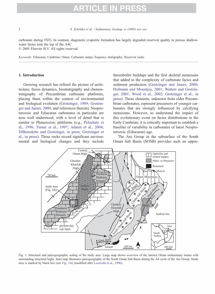
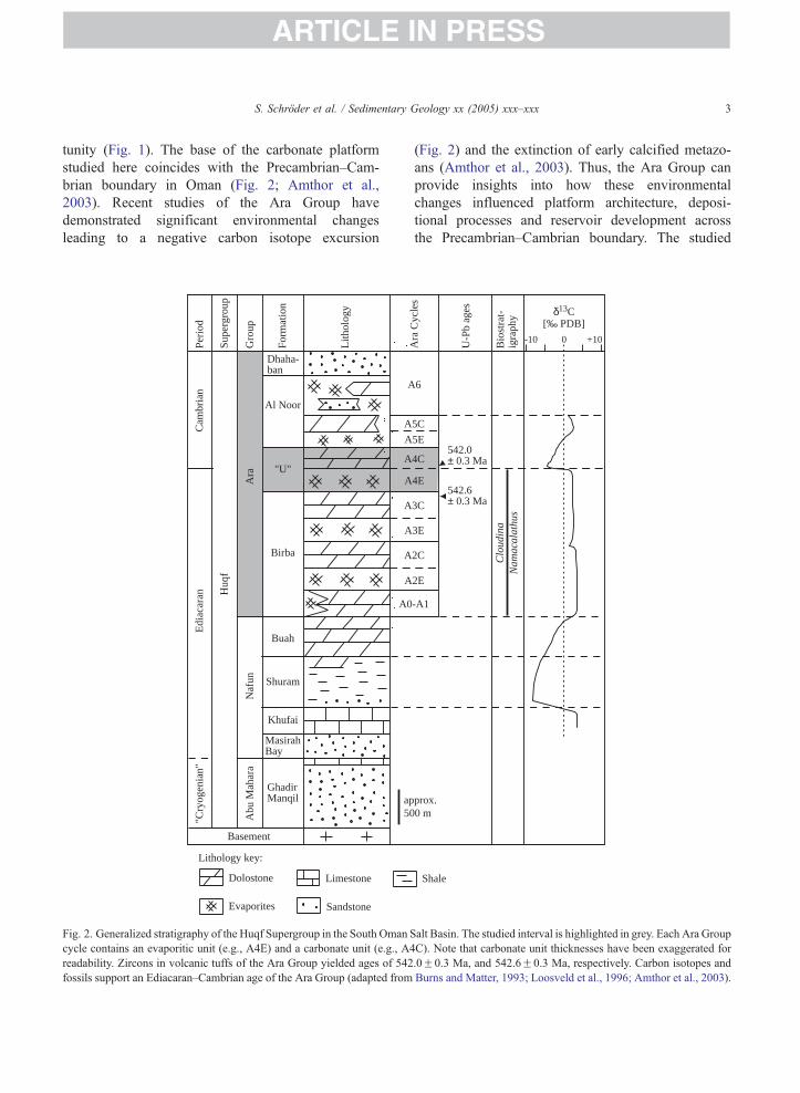
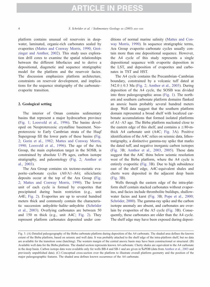
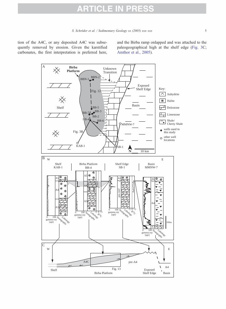


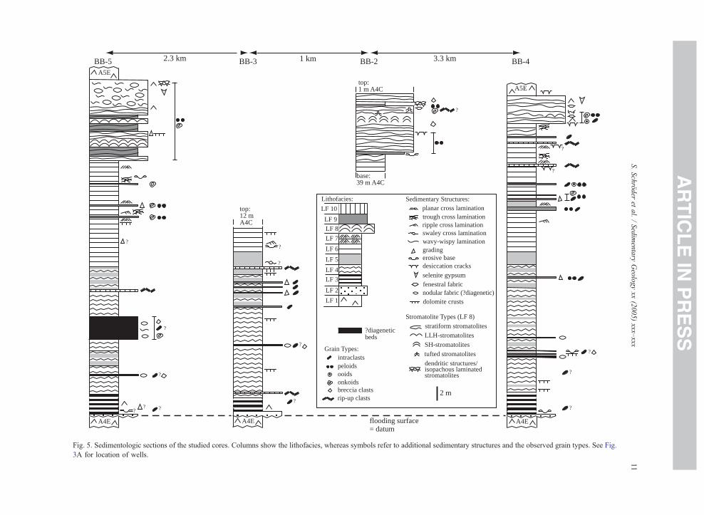
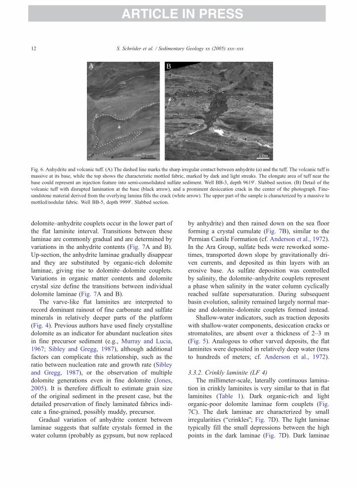
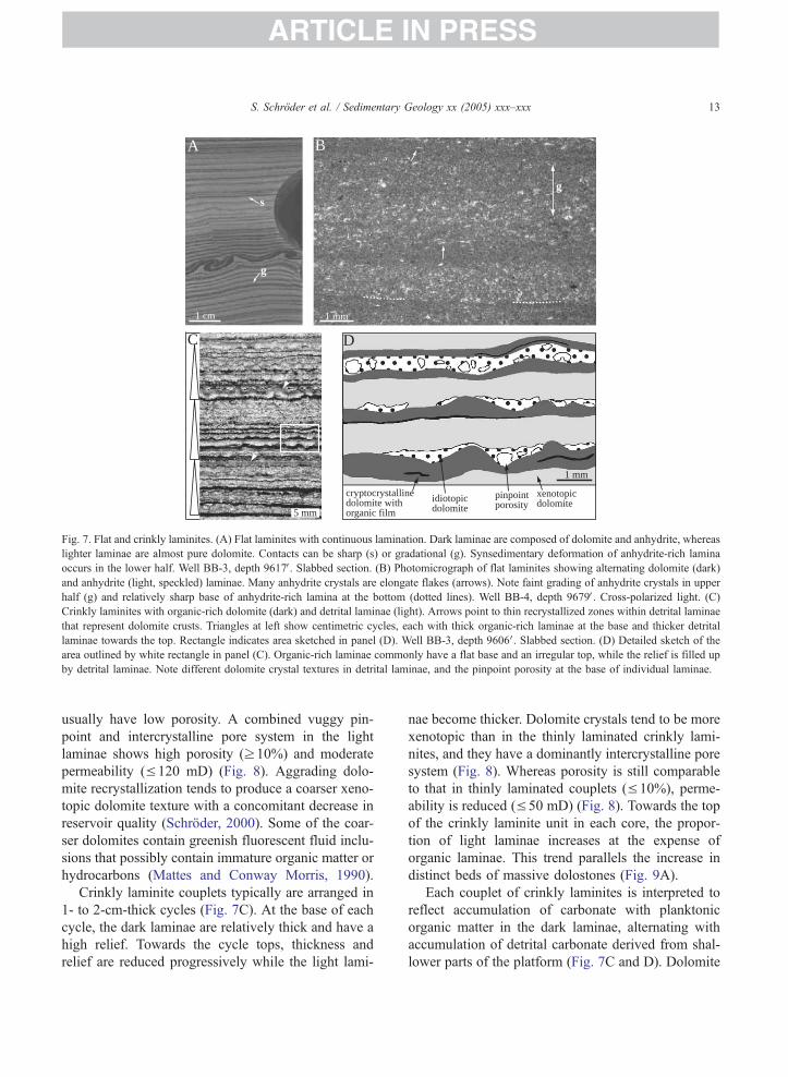
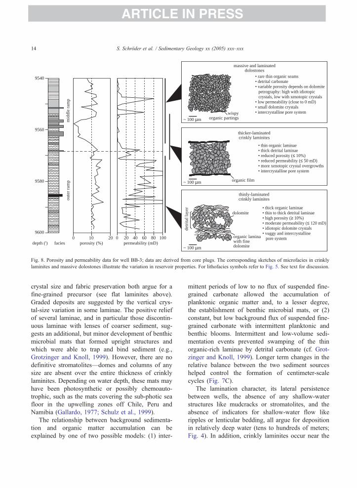

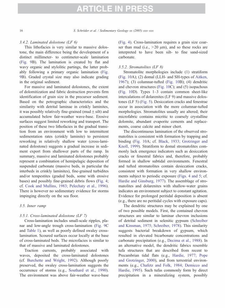

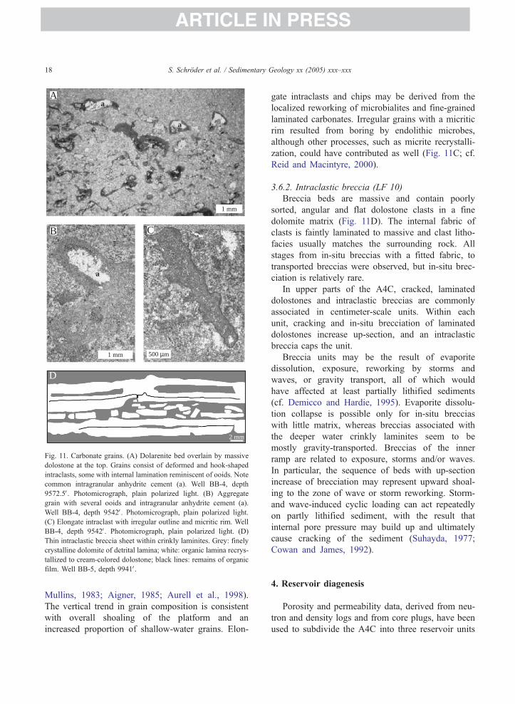
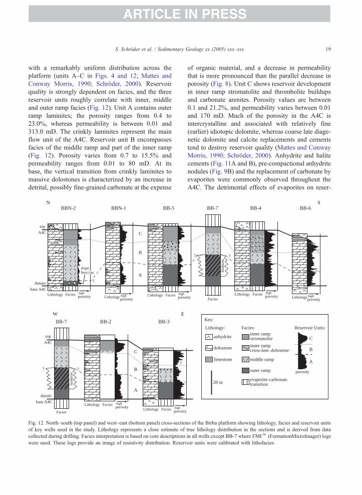
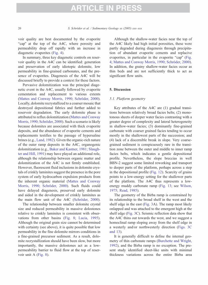
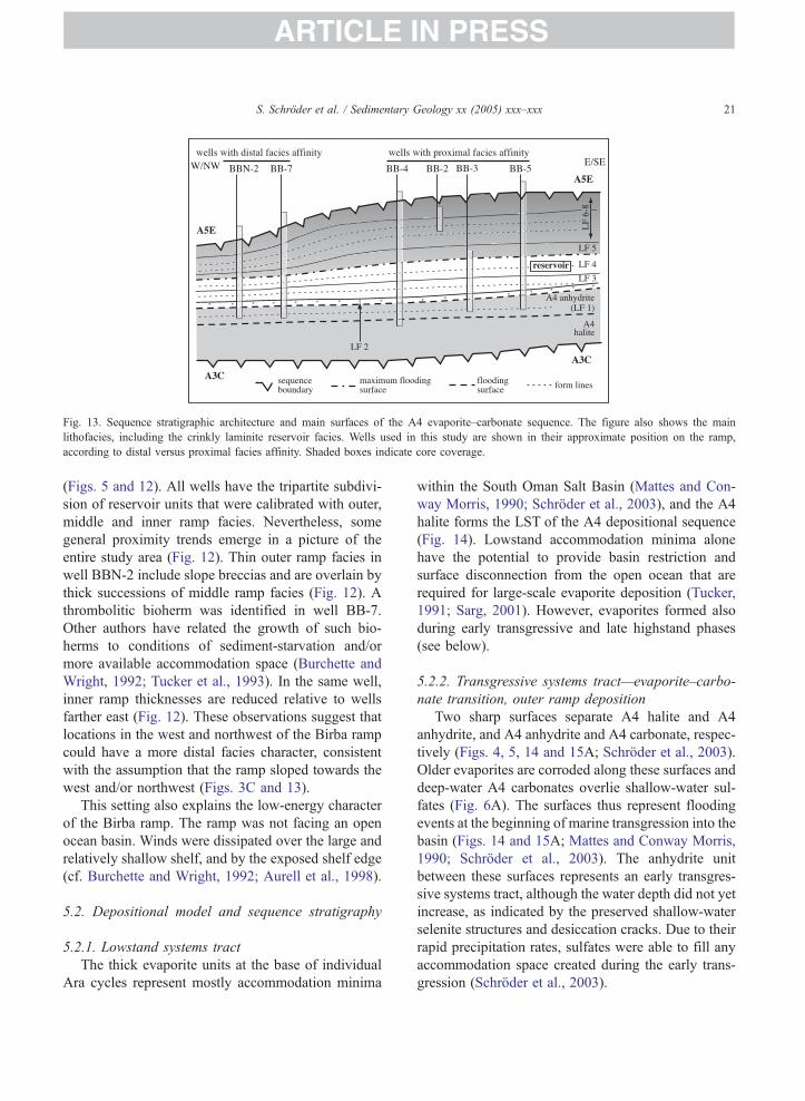
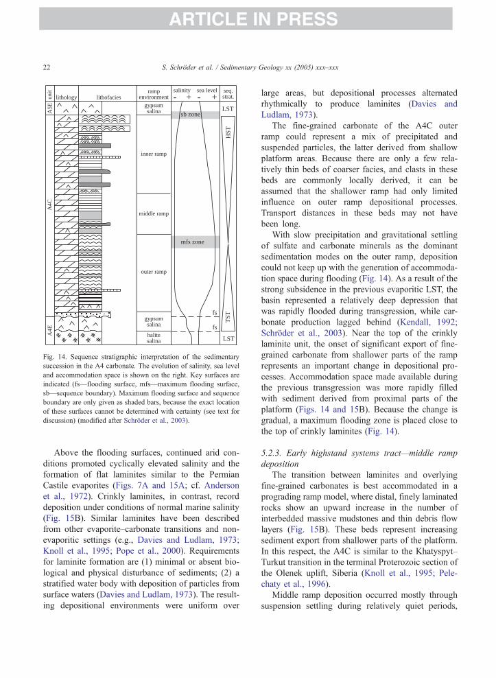
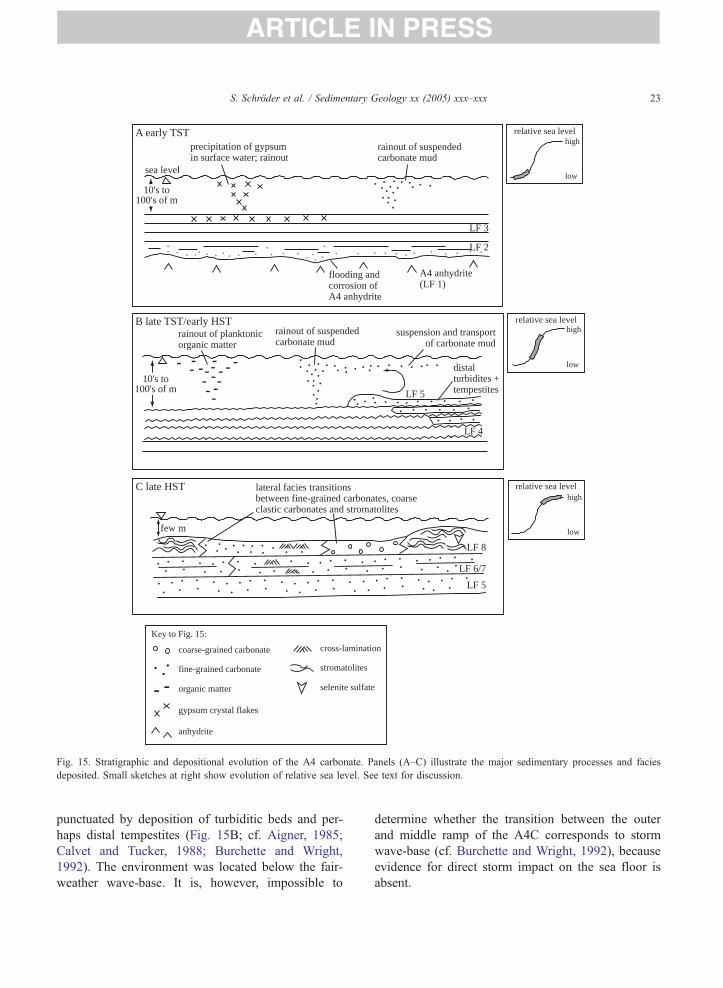


![PETROLEUM DEVELOPMENT OMAN (PDO) [Elmech] Development Oman - PDO [Elmec… · Petroleum Development Oman L.L.C. ... Postal Address : P.O.BOX 505- PC 114- SULTANATE OF OMAN Is registered](https://static.documents.pub/doc/80x56/5ac633c57f8b9a5c558dcb76/petroleum-development-oman-pdo-elmech-development-oman-pdo-elmecpetroleum.jpg)