NASA Technical Memorandum 100192 Dynamic Delamination Buckling in Composite Laminates Under Impact Loading: Commtational A Simulation Joseph E. Grady, Christos C. Chamis, and Robert A. Aiello Lewis Research Center Cleveland, Ohio (liASA-TR- 100 192) OYNBMIC CELACIbA'XIOtl 187-2 86 11 EGCRLISG IY CCHfCSlfE LAMIIA'III UdlDEB IMPACT LCADZYG: CCUPCIAIICBAL SIZPTULA'IICli (NASA) 74 p Avail: 13115 RC 102/BF A01 CSCL 11D Unclas G3/24 00976 16 Prepared for the Second Symposium on Composite Materials: Fatigue and Fracture sponsored by the American Society for Testing and Materials Cincinnati, Ohio, April 26-30, 1987 9 - https://ntrs.nasa.gov/search.jsp?R=19870019178 2018-05-22T05:38:28+00:00Z
Transcript
NASA Technical Memorandum 100192
Dynamic Delamination Buckling in Composite Laminates Under Impact Loading: Commtational A Simulation
Joseph E. Grady, Christos C. Chamis, and Robert A. Aiello Lewis Research Center Cleveland, Ohio
(liASA-TR- 100 192) OYNBMIC CELACIbA'XIOtl 187-2 86 11 EGCRLISG I Y C C H f C S l f E LAMIIA'III UdlDEB IMPACT LCADZYG: CCUPCIAIICBAL SIZPTULA'IICli ( N A S A ) 74 p A v a i l : 13115 RC 102/BF A01 CSCL 11D Unclas
G3/24 00976 16
Prepared for the Second Symposium on Composite Materials: Fatigue and Fracture sponsored by the American Society for Testing and Materials Cincinnati, Ohio, April 26-30, 1987
DYNAMIC DELAMINATION BUCKLING I N COMPOSITE LAMINATES UNDER
IMPACT LOADING: COMPUTATIONAL SIMULATION
Joseph E. Grady, Chr i s tos C. Chamis, and Robert A . A i e l l o Nat iona l Aeronaut ics and Space . A d m i n i s t r a t i o n
Lewis Research Center Cleveland, Ohio 44135
SUMMARY
A unique dynamic de laminat ion buck l i ng and de laminat ion propagat ion analy-
p u t e r program. This c a p a b i l i t y cons is ts o f : t i m e i n t e g r a t i o n s o l u t i o n sequence which prov ides a new a n a l y s i s a l g o r i t h m t h a t can be used t o p r e d i c t de laminat ion buck l i ng i n a laminate subjected t o dynamic load ing , and (2) a new method o f modeling the composite laminate us ing p l a t e bending elements and m u l t i p o i n t cons t ra in t s . Th is computer program i s used t o
Q, p r e d i c t bo th impact induced buck l i ng i n composite laminates w i t h i n i t i a l delam- i n a t i o n s and the s t r a i n energy re lease r a t e due t o ex tens ion o f the delamina- t i o n . I t i s shown t h a t de laminat ions near the ou te r sur face o f a laminate are suscep t ib le t o l o c a l buck1 i n g and buckl ing- induced de laminat ion propagat ion when the laminate i s subjected t o t ransverse impact load ing . The c a p a b i l i t y now e x i s t s to p r e d i c t the t i m e a t which the onset o f dynamic de laminat ion buck- l i n g occurs, the dynamic b u c k l i n g mode shape, and the dynamic de laminat ion s t r a i n energy re lease r a t e .
s i s c;lp;lh!!ify h;lS bee!! de?le!nped 2nd !ncorporated in tc a f i n i t e element corn= ( 1 ) a m o d i f i c a t i o n o f the d i r e c t
INTRODUCTION
Composite laminates are sub jec t to delaminat ion, which causes a loss o f bo th s t i f f n e s s and s t reng th . Delaminat ion i s genera l l y induced by s t a t i c , dynamic, or f a t i g u e load ing . Delaminated sublaminates are p a r t i c u l a r l y suscep- t i b l e to dynamic l o c a l b u c k l i n g when subjected to impact load ing . The p red ic - t i o n o f impact-induced dynamic delaminat ion b u c k l i n g i s necessary for e v a l u a t i n g the d u r a b i l i t y o f many composite s t r u c t u r e s and i s , t he re fo re , t he t o p i c o f t h i s paper.
The delaminat ion buck l i ng phenomenon has been observed exper imen ta l l y under s t a t i c and f a t i g u e load ing cond i t ions ( r e f s . 1 t o 41, and severa l ana ly t - i c a l methods have been proposed to model t h i s damage mechanism. One- dimensional beam models and f r a c t u r e mechanics approaches ( r e f s . 5 and 6) have been used t o gauge the s t a b i l i t y o f de laminat ions i n compressively loaded lami- nates. F i n i t e element approaches ( r e f s . 7 and 8) are often used for these ana lys i s .
I n the course o f e a r l i e r research, exper imental observa t ions o f dynamic de laminat ion buck l i ng i n t ransve rse l y impacted laminates were repo r ted ( r e f . 9) based on high-speed photography o f t h e de laminat ion b u c k l i n g sequence. This work mot iva ted the present development o f a f i n i t e element a n a l y s i s technique t o p r e d i c t the occurrence o f impact-induced dynamic b u c k l i n g i n laminates w i t h de laminat ions . I t has been shown ( r e f s . 9 and 10) t h a t the mechanism causing
extens ion o f a de laminat ion depends on the l o c a t i o n of t h a t de laminat ion w i t h i n the impacted laminate. A de laminat ion a long t h e midplane of a symmetrical lam- i n a t e w i l l i n i t i a l l y extend i n a predominant ly Mode I 1 fash ion . o f f the midplane ( c l o s e r to t h e o u t e r sur face) o f a laminate, however, a re sus- c e p t i b l e t o buck l ing caused by compressive s t r e s s i n t h e delaminated reg ion .
This l o c a l b u c k l i n g may then induce a Mode I dominated ex tens ion o f the delaminat ion. I n t h e l a t t e r case, t h e a b i l i t y t o p r e d i c t the onset o f dynamic delaminat ion buck l ing i s e s s e n t i a l to determine i f ex tens ion o f t h e delamina- t i o n w i l l occur when t h e laminate i s sub jec ted t o a g iven impact load. The ob- j e c t i v e s of t h i s paper are: dynamic delaminat ion b u c k l i n g and de laminat ion propagat ion, and ( 2 ) t o present t y p i c a l r e s u l t s of t h i s procedure for a de l aminated composi t e 1 aminate under impact load ing .
Delaminat ions
(1) t o o u t l i n e t h e computat ional procedure for
DYNAMIC BUCKLING ANALYSIS
To per form the dynamic de laminat ion b u c k l i n g a n a l y s i s , t h e d i r e c t t ime
The b u c k l i n g analy- i n t e g r a t i o n s o l u t i o n sequence i n the f i n i t e element program i s a l t e r e d so t h a t a l i n e a r buck l ing a n a l y s i s i s performed a t each t ime step. s i s r e q u i r e s so lu t ions o f t h e e igenvalue problem:
[CKI + X[K,I] {4} = 0 ( 1 )
where
CKI i s t h e s t r u c t u r a l s t i f f n e s s m a t r i x
CK,l i s t h e s t ress s t i f f n e s s m a t r i x
The f o r m u l a t i o n o f these mat r ices f o r t h e NASTRAN Quad-4 p l a t e element used here i s g i v e n i n re fe rence 11.
Each s c a l a r eigenvalue s a t i s f y i n g equat ion (1) p h y s i c a l l y represents t h e nondi- mensional r a t i o
where u i s the time-dependent compressive l o n g i t u d i n a l s t r e s s i n t h e delaml- nated sublaminate, A i s t h e c ross-sec t iona l area o f the sublaminate, and P, i s the c r i t i c a l compressive load t h a t w i l l cause b u c k l i n g o f t h e sublaminate. When an eigenvalue reaches the c r i t i c a l va lue o f u n i t y (uA = P * ) , b u c k l i n g i n t h a t mode occurs. The e igenvectors {I$} assoc ia ted w i t h each e igenvalue a r e the corresponding dynamic b u c k l i n g mode shapes. F igure 1 i s a f l o w c h a r t o f the m o d i f i e d s o l u t i o n procedure. Th is a l t e r e d f i n i t e element s o l u t i o n proce- dure was implemented i n Vers ion 65A o f MSUNASTRAN us ing NASTRAN DMAP a l t e r s . The complete m o d i f i c a t i o n i s shown i n the NASTRAN DMAP A l t e r sequence i n Appendix A .
I 2
F I N I T E ELEMENT MODELING PROCEDURE
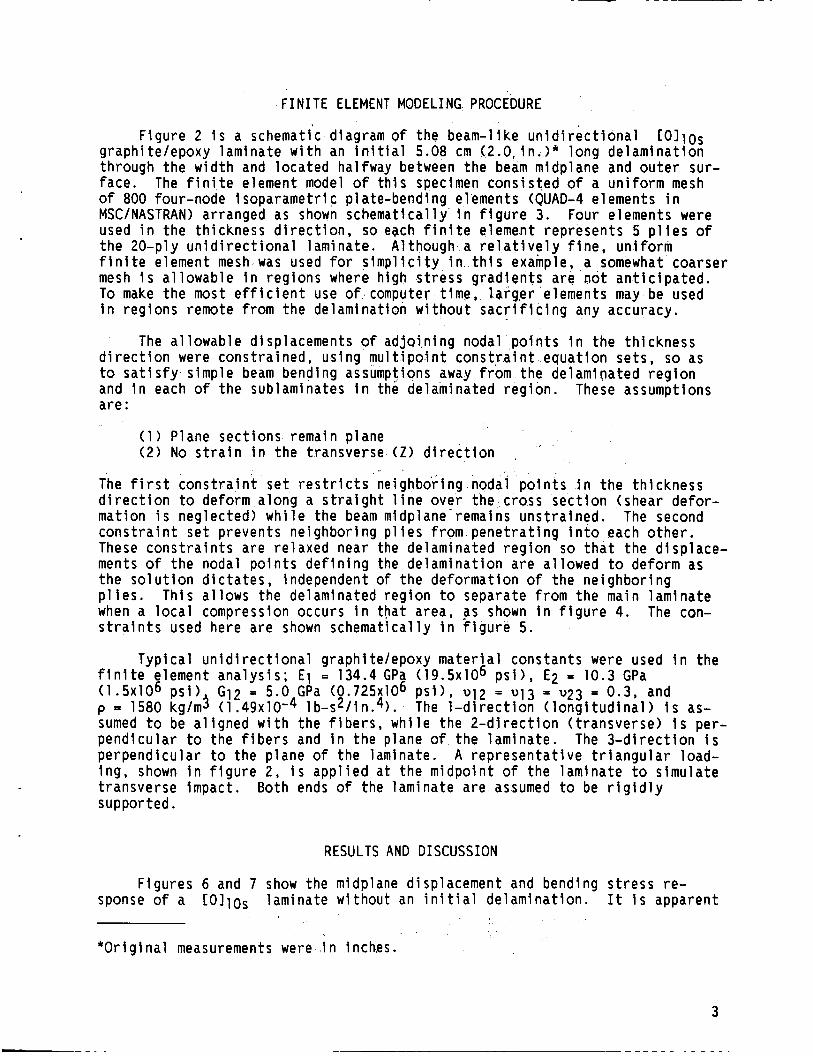
F igure 2 i s a schematic diagram of the beam-l ike u n i d i r e c t i o n a l C O l l o s g raph i te lepoxy laminate w i t h an i n i t i a l 5.08 cm (2.0, i n . > * long de laminat ion through t h e w i d t h and loca ted halfway between the beam midplane and o u t e r sur- face. The f i n i t e element model o f t h i s specimen c o n s i s t e d o f a u n i f o r m mesh of 800 four-node isoparamet r ic plate-bending elements (QUAD-4 elements i n MSClNASTRAN) arranged as shown schemat ica l ly i n f i g u r e 3 . Four elements were used i n t h e th ickness d i r e c t i o n , so ebch f i n i t e element represents 5 p l i e s o f t h e 20-ply u n i d i r e c t i o n a l laminate. Al though a r e l a t i v e l y f i n e , u n i f o r m f i n i t e element mesh was used f o r s i m p l i c i t y i n t h i s example, a somewhat coarser mesh i s a l lowab le i n reg ions where high s t r e s s g r a d i e n t s are not a n t i c i p a t e d . To make t h e most e f f i c i e n t use o f computer t ime, l q r g e r elements may be used i n reg ions remote from t h e delaminat ion w i t h o u t s a c r i f i c i n g any accuracy.
The a1 lowable displacements of adjoi .n ing nodal p o i n t s i n t h e th ickness d i r e c t i o n were const ra ined, us ing m u l t i p o i n t c o n s t r a i n t equat ion sets , so as to s a t i s f y s imple beam bending assumptions away from the delaminated r e g i o n and i n each o f the sublaminates i n the delaminated r e g i o n . a re :
These assumptions
(1 ) Plane sec t ions remain plane (2 ) No s t r a i n i n t h e t ransverse ( Z ) d i r e c t i o n , '
. . The f i r s t c o n s t r a i n t $ e t r e s t r i c t s ne ighbor ing nodal p o i n t s i n t h e th ickness d i r e c t i o n t o deform a long a s t r a i g h t l i n e over the cross s e c t i o n (shear de for - mat ion i s neglected) w h i l e the beam midplane'remains uns t ra ined. The second c o n s t r a i n t s e t prevents ne ighbor ing p l i e s from p e n e t r a t i n g i n t o each o t h e r . These c o n s t r a i n t s are r e l a x e d near the delaminated r e g i o n so t h a t t h e d isp lace- ments of the nodal p o i n t s d e f i n i n g the de laminat ion are a l lowed t o deform as t h e s o l u t i o n d i c t a t e s , independent of t h e deformat ion o f t h e ne ighbor ing p l i e s . Th is a l lows the delaminated reg ion t o separate from t h e main laminate when a l o c a l compression occurs i n t h a t area, as shown i n f i g u r e 4. The con-
used here are shown schemat lca l ly i n f i g u r e 5. s t r a i n t s
TY P f i n i t e e (1.5x10⁶
sumed t o pendi cu 1
p = 1580
c a l u n i d i r e c t i o n a l graphi te lepoxy m a t e r i a l constants were used i n the ement a n a l y s i s ; E1 = 134.4 GPa ( 1 9 . 5 ~ 1 0 6 p s i ) , E2 = 10.3 GPa p s i ) G12 = 5.0 GPa ( 0 . 7 2 5 ~ 1 0 ~ p s i ) , v i 2 = v i 3 = v23 = 0.3, and k g l d (1.49~10'4 l b - ~ 2 l i n . ~ ) . be a l i g n e d w i t h the f i b e r s , w h i l e t h e 2 - d i r e c t i o n ( t ransverse) i s per- r t o the f i b e r s and i n the plane o f t h e laminate. The 3 - d i r e c t i o n i s
The 1 - d i r e c t i o n ( l o n g i t u d i n a l ) i s as-
perpend icu la r t o the p lane o f the laminate. A r e p r e s e n t a t i v e t r i a n g u l a r load- ing , shown i n f i g u r e 2, i s a p p l i e d a t t h e midpo in t of the laminate t o s imu la te t ransverse impact. supported.
Both ends o f the laminate are assumed to be r i g i d l y
RESULTS AND DISCUSSION
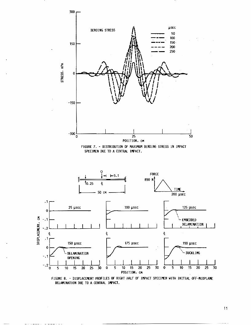
F igures 6 and 7 show the midplane displacement and bending s t r e s s r e - sponse of a COl1os laminate w i thout an i n i t i a l de laminat ion . I t i s apparent
* O r i g i n a l measurements were i n inches.
3
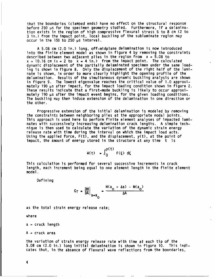
t h a t the boundaries (clamped ends) have no e f fec t on the s t r u c t u r a l response be fore 250 ps f o r t he specimen geometry s tud ied . Furthermore, i f a delamina- t i o n e x i s t s i n the r e g i o n of h i g h compressive f l e x u r a l s t ress 5 t o 8 cm ( 2 to 3 i n . ) f rom the Impact p o i n t , l o c a l b u c k l i n g of the sublaminate r e g i o n may
o 250 ps i n t e r v a l . occur i n the 150
A 5.08 cm ( 2 i n t o the f i n i t e e descr ibed between x = 10.16 cm ( x =
0 i n . ) long, o f f -midplane de laminat ion i s now in t roduced ement model as shown i n f i g u r e 4 by removing the c o n s t r a i n t s two ad jacent p l i e s i n the r e g i o n from x = 5.08 to 2 to x = 4 in . ) from the impact p o i n t . The c a l c u l a t e d
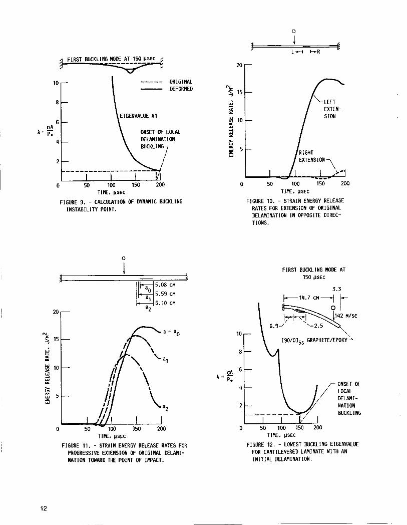
dynamic displacement o f the p a r t i a l l y delaminated specimen under the same load- i n g i s shown i n f i g u r e 8. Only the displacement of t h e r i g h t h a l f of the lami- na te i s shown, i n o r d e r t o more c l e a r l y h i g h l i g h t the opening p r o f i l e o f the delaminat ion. R e s u l t s of the simultaneous dynamic b u c k l i n g a n a l y s i s a re shown i n f i g u r e 9. The lowest e igenvalue reaches the c r i t i c a l va lue o f 1.0 approx i - mate ly 190 ps a f t e r impact, for the Impact l oad ing c o n d i t i o n shown i n f i g u r e 2. These r e s u l t s i n d i c a t e t h a t a f i rs t -mode b u c k l i n g i s l i k e l y to occur approx i - mate ly 190 ps a f t e r t he impact event begins, for the g iven load ing cond i t i ons . The buck l i ng may then induce ex tens ion o f the de laminat ion i n one d i r e c t i o n or the o the r .
Progressive ex tens ion o f the i n i t i a l de laminat ion i s modeled by removing the c o n s t r a i n t s between ne ighbor ing p l i e s a t the approp r ia te nodal p o i n t s . Th is approach i s used here t o per fo rm f i n i t e element analyses of impacted lami- nates w i t h success ive ly i n c r e a s i n g de laminat ion c rack lengths . A s imple tech- n ique i s then used to c a l c u l a t e the v a r l a t i o n of the dynamic s t r a i n energy re lease r a t e w i th t ime d u r i n g the i n t e r v a l on which the impact load ac ts . Using the app l ied fo rce , F ( t ) , and the displacement, y ( t ) , a t the p o i n t o f impact, the amount of energy s to red I n the s t r u c t u r e a t any t i m e t i s
Th is c a l c u l a t i o n I s performed f o r severa l successive Increments i n c rack length , each increment be ing equal t o one element l e n g t h i n the f i n i t e element model.
D e f i n i ng
W(ao + Aa) - W(ao> AA = GT =
a=ao
as the t o t a l s t r a i n energy re lease r a t e ;
where
a = crack length
A = crack area
the v a r i a t i o n of s t r a i n energy re lease r a t e w i t h t ime a t each t i p of the 5.08 cm (2.0 i n . ) long i n i t i a l de laminat ion i s shown i n f i g u r e 10. Th is i n d i - cates t h a t , i n the absence o f f l e x u r a l wave r e f l e c t i o n s from the boundar ies,
4
~- ~
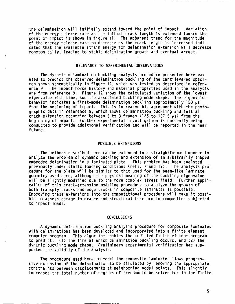
the delaminat ion w i l l i n i t i a l l y extend/towat-d the p o i n t o f impact. V a r i a t i o n o f the energy re lease r a t e as the i n i t i a l c rack l e n g t h i s extended toward the p o i n t of impact i s shown i n f i g u r e 11. o f the energy re lease r a t e to decrease as the c rack l e n g t h i s increased i n d i - cates t h a t the a v a i l a b l e s t r a i n energy for de laminat ion ex tens ion w i l l decrease monotonica l ly , l ead ing to s tab le de laminat ion growth and eventual a r r e s t .
The apparent t r e n d f o r the magnitude
RELEVANCE TO EXPERIMENTAL OBSERVATIONS
The dynamic de laminat ion buck l ing a n a l y s i s procedure presented here was used t o p r e d i c t the observed delaminat ion b u c k l i n g of the c a n t i l e v e r e d speci- men shown schemat ica l l y i n f i g u r e 12, which was tes ted as descr ibed i n r e f e r - ence 9. The impact f o r c e h i s t o r y and m a t e r i a l p r o p e r t i e s used i n the a n a l y s i s are from re ference 9. F igure 52 shows the c a i c u i a t e a v a r i a t i o n o f the i owes t e igenvalue w i t h t i m e , and the associated buck1 i n g mode shape. The e igenvalue behavior i n d i c a t e s a f i rs t -mode delaminat ion b u c k l i n g approx imate ly 150 ps f rom the beginning o f impact. g raph ic data i n re fe rence 9, which shows de laminat ion b u c k l i n g and i n i t i a l c rack ex tens ion o c c u r r i n g between 2 to 3 frames (125 t o 187.5 ps) from the beginning o f impact. Fur ther experimental i n v e s t i g a t i o n i s c u r r e n t l y be ing conducted to prov ide a d d i t i o n a l v e r i f i c a t i o n and w i l l be repo r ted i n the near f u t u r e .
This i s i n reasonable agreement w i t h the photo-
The methods analyze the prob
POSSIBLE EXTENSIONS
descr ibed here can be extended i n em o f dynamic buck l ing and extens
a s t ra igh t fo rward manner t o on o f an a r b i t r a r i l y shaped
embedded de laminat ion i n - a laminated p l a t e . p r e v i o u s l y under s t a t i c l oad ing cond i t ions ( r e f s . 7 and 12). The a n a l y s i s pro- cedure for the p l a t e w i l l be s i m i l a r t o t h a t used for the beam-like laminate geometry used here, a l though the phys ica l meaning o f the buck l i ng e igenvalue w i l l be s l i g h t l y mod i f ied due t o the more complex s t r e s s f i e l d . Fu r the r a p p l i - c a t i o n o f t h i s crack-extens ion modeling procedure to analyze the growth o f bo th t r a n s p l y cracks and edge cracks i n composite laminates i s p o s s i b l e . Embodying these extens ions i n t o the computat ional procedure w i l l make i t poss i - b l e t o assess damage to le rance and s t r u c t u r a l f r a c t u r e i n composites sub jec ted t o impact loads.
Th is problem has been analyzed
CONCLUSIONS
A dynamic de laminat ion buck l i ng a n a l y s i s procedure fo r composite laminates w i t h de laminat ions has been developed and incorpora ted i n t o a f i n i t e element computer program. t o p r e d i c t : ( 1 ) the t ime a t which delaminat ion b u c k l i n g occurs, and (2) the dynamic b u c k l i n g mode shape. P re l im ina ry exper imenta l v e r i f i c a t i o n has sup- po r ted the v a l i d i t y of the ana lys i s .
Th is a l g o r i t h m enables the mod i f i ed f i n i t e element program
The procedure used here to model the composite laminate a l l ows progres- s i v e ex tens ion of the de laminat ion t o be s imulated by removing the approp r ia te c o n s t r a i n t s between displacements a t ne ighbor ing nodal p o i n t s . Th is s l i g h t l y increases the t o t a l number o f degrees o f freedom t o be so lved f o r i n t h e f i n i t e
element ana lys is , w h i l e keeping the number of elements and t h e element mesh constant as the crack extends. Th is procedure g r e a t l y s i m p l i f i e s the simula- t i o n of progressive c rack ex tens ion . de laminat ion s t r a i n energy re lease r a t e for a composite laminate under impact 1 oadi ng .
Resu l ts obtained show t h a t : ( 1 ) de laminat ions near t h e o u t e r su r face o f a laminate t h a t i s subjected to t ransverse impact l o a d i n g a re s u s c e p t i b l e t o dynamic buckl i ng and buckl ing-induced propagat ion, and (2) I n the absence of boundary e f f e c t s , t ransverse impact a t a p o i n t near a de lamina t ion w i l l cause t h e delaminat ion to propagate toward the p o i n t o f impact, w i t h l i t t l e or no ex tens ion I n the oppos i te d i r e c t i o n .
I t was used t o c a l c u l a t e t h e dynamic
Fu r the r a p p l i c a t i o n o f t h i s procedure to the problem o f b u c k l i n g and prop- I n addi- aga t ion of an embedded de laminat ion I n a laminated p l a t e i s poss ib le .
t i o n , s i m i l a r techniques can be used to model d i f f e r e n t f l a w types such as t r a n s p l y cracks and edge cracks. b l e t o computational l y assess the damage to le rance of compos1 t e s t r u c t u r e s w i t h i n i t i a l or induced de fec ts when sub jec ted to impact load ing .
With these m o d i f i c a t i o n s i t would be poss i -
REFERENCES
1 . G i l l e s p i e , J.W., and Pipes, R.B., Composite S t ruc tu res , Vol. 2, No. 1, 1984, pp. 49-69.
2, Rosenfeld, M.S., and Gause, L.W., i n Fa t igue o f F ib rous Composite Ma te r i - - a l s , ASTM STP-723, American Soc ie ty for Tes t i ng and M a t e r i a l s , P h i l a d e l - ph ia, 1981, pp. 174-196.
3. Kon ish i , D.Y., and Johnston, W.R., i n Composite M a t e r i a l s : Tes t i ng and Desiqn ( F i f t h Conference), ASTM STP-674, S.W. Tsai , Ed., American Soc ie ty for Tes t i ng and M a t e r i a l s , P h i l a d e l p h i a , 1979, pp. 597-619.
4. Chai, H., Knauss, W.G., And Babcock, C.D. , Experimental Mechanics, Vol. 23, No. 3, Sept. 1983, pp. 329-337.
5. Chai, H., Babcock, C.D., and Knauss, W.G., I n t e r n a t i o n a l Journal of S o l i d s and St ruc tures , Vol. 17, No. 11, 1981, pp. 1069-1083.
6. Whitcomb, J.D., i n E f fec ts o f Defec ts I n Composite M a t e r i a l s , ASTM STP-836, American Soc ie ty for Tes t i ng and M a t e r i a l s , P h i l a d e l p h i a , 1984, pp. 175-193.
- -
7. Whitcomb, J.D., Journal of Composite M a t e r i a l s , Vol. 15, No. 5, Sept. 1981, pp. 403-426.
8. Kapania, R.K., and Wolfe, D.R. , I n 28 th A I A A I A S M E I A S C E I A H S S t r u c t u r e s , S t r u c t u r a l Dynamics, and M a t e r i a l s Conference, American I n s t i t u t e of Aero- n a u t i c s and As t ronaut ics , New York, 1987, pp. 766-775.
9. Grady, J.E., and Sun, C.T., i n Composite M a t e r i a l s : Fa t i gue and F rac tu re , ASTM STP-907, H.T. Hahn, Ed. , American Society for Tes t i ng and M a t e r i a l s , Ph i l ade lph ia , 1986, pp. 5-31.
10. Simitses, G.J., and Sallam, S., "Delamination Buckling and Growth o f Flat Composite Structural Elements," AFOSR-85-1067TR, Sept. 1984. (Avail. NTIS, AD-A162370).
12. Whitcomb, J.D., and Shivakumar, K.N., "Strain-Energy Release Rate Analysis o f a Laminate with a Postbuckled Delamination,'' NASA TM-89091, National Aeronautics and Space Administration, Washington, D.C., 1987.
7
Add r e s s Modu 1 e Func t ion
5 9
10 11
12-22 24 25 27
29 30 31 32 37
LABEL MATMOD
EMG EMA
ADD DPD READ
OFP SDRl SDR2 OFP REPT
Begin buck1 i n g a n a l y s i s S t r i p displacement v e c t o r (6) from t r a n s i e n t s o l u t i o n m a t r i x
Generate element s t r e s s s t i f f e n i n g mat r ices , [k,l Assemble g l o b a l s t r e s s s t i f f e n i n g m a t r i x , CK,I E l im ina te boundary c o n d i t i o n s ; reduce [K,1 Mu1 t i p l y [K,l by ( - 1 .O) Red e igenvalue e x t r a c t i o n da ta from i n p u t Eigenvalue e x t r a c t i o n :
so lve CKI + MK,I
a t each t ime step
(9) = 0 for e igenvalues and e igenvectors [ I Format and p r i n t e igenvalues Recover dependent degrees o f freedom for e igenvectors Prepare e igenvectors f o r o u t p u t Format and p r i n t e igenvectors Return t o address 5
READ INPUT DATA I
MASS MATRICES
I I I REAL E I GENVALUE I
4 EXTRACTION f CALCULATE EIGENVECTORS -
v I . 1 J
FORM APPLIED
I I I
I I I
I
FORM STRESS 1 STIFFNESS MATRIX, --.) PARTITION [KO] - RECOVER CURRENT DISPLACEMENTS (6)
INTEGRATE EQUATIONS OF MOTION:
I
KO = KO(6) I t = t + A t I
I
J
FIGURE 1. - DYNAMIC BUCKLING ANALYSIS FLOW CHART.
FORCE A
890 N
TIME
F /k
k k 50.8 CM _ I
FIGURE 2 . - I R A C T SPECIEN GEOMETRY AND LOADING.
r 2 ELEMENTS
e 1 . 2 7 C M 4
L'4 ELEMENTS TYPICAL ELEMENT
FIGURE 3. - F I N I T E ELEMENT MODEL OF IMPACT SPEC I N N .
2
t
FIGURE 4. - IMPACT SPECIMEN AND BUCKLED SUBLAMINATE.
9
----- ORIGINAL DEFORMED
2.W A
.125
U4
CONSTRAINTS IMPOSED AT EACH LONGITUDINAL STATION 'I' : 1 . UNIFORM ROTATION AT EACH CROSS SECTION
8i 8 i = 1,2.3.4
ui - ui+l = t e
2 . PLANE SECTIONS REWIN PLANE
i = 1.2,3
3. NO TRANSVERSE STRAIN ( E ~ = 0)
W i w i = 1.2,3,4
FIGURE 5 . - EXAGGERATED DEFORMATION OF F I N I T E ELEMENT MODEL.
FORCE 4
0 890
r I DISPLACEMENT
N
r O V
I-
3 W u 4 z a.
-.125 a
10
300
150
4 Y
2 0 ? cn
-150
-300 0 25 50
POSITION. CM
FIGURE 7. - DISTRIBUTION OF MAXIMUM BENDING STRESS I N IMPACT SPECIMEN DUE TO A CENTRAL IMPACT.
0 i-l b 5 . 1 FORCE -
890 Nh TIME
P t0.25 e
1-. 50 CM 1 200 VSEC
':Il 1 2 5 ; ~ l , , l l O O ~ C , , I k , , l 2 5 ; ~ , I , r EMBEDDED " - . I
c DELAM I NATION L y -.2
g e -I e t n ' ':b, 150 ;c, I , k, 1 7 5 , p ~ ~ c ~ , , k 1 9 0 ;c, , ,
FIGURE 8. - DISPLACEENT PROFILES OF RIGHT HALF OF IMPACT SPECIKN WITH I N I T I A L OFF-MIDPLANE DELANINATION DUE TO A CENTRAL IMPACT.
11
OA h = - P I
lo r ----- ORIGINAL - DEFORMED
6 EIGENVALUE #1 \ ONSET OF LOCAL
8 b
-
I 1 I I ' I !r I
0 50 100 150 200 TIRE. k S E C
FIGURE 9. - CALCULATION OF DYNAMIC BUCKLING I NSTABI L I T Y POINT.
2o r (u
5 15- W c 2
3
%
$
!5
10-
W c*
= 5 -
I
OA h = - P+
0 50 100 150 200 T I E , P S E C
FIGURE 10. - STRAIN ENERGY RELEASE RATES FOR EXTENSION OF ORIGINAL DELAMINATION I N OPPOSITE DIREC- TIONS.
0
3 k 5.08 CM
5.59 CM
6.10 CM
0
0 100 150 200 TIME, p S E C
FIGURE 11. - STRAIN ENERGY RELEASE RATES FOR PROGRESSIVE EXTENSION OF ORIGINAL DELAMI- NATION TOWARD THE POINT OF IMPACT.
FIRST BUCKLING MODE AT 150 MSEC
3 .3 b 1 4 . 7 CM- I-
ONSET OF LOCAL DELAHI- NATION BUCKLING
TIME. p S E C
FIGURE 12. - LOWEST BUCKLING EIGENVALUE FOR CANTILEVERED LAMINATE WITH AN I N I T I A L DELAMINATION.
12
National Aeronautics and
1. Report No.
NASA TM- 1 00 1 92
Report Documentation Page 2. Government Accession No.
9. Security Classif. (of this report) 20. Security Classif. (of this page) 21. No of pages
Uncl ass i f i ed U n c l a s s i f i e d 13
Dynamic Delaminat ion Buck l ing i n Composite Laminates Under Impact Loading: Computational S i m u l a t i o n
22. Price'
A02
7. Author($
Joseph E . Grady, Chr is tos C. Chamis, and Robert A. A i e l l o
9. Performing Organization Name and Address
Nat ional Aeronautics and Space A d m i n i s t r a t i o n Lewis Research Center Cleveland, Ohio 44135-3191
Nat ional Aeronautics and Space A d m i n i s t r a t i o n Washington, D.C. 20546-0001
2. Sponsoring Agency Name and Address
5. Supplementary Notes
3. Recipient's Catalog No.
~~
5. Report Date
6. Performing Organization Code
8. Performing Organization Report No.
E-3779
10. Work Unit No.
505-63-1 1 11. Contract or Grant No.
13. Type of Report and Period Covered
Technica l Memorandum 14. Sponsoring Agency Code
Prepared fo r t h e Second Symposium on Composite M a t e r i a l s : t u r e , sponsored by t h e American S o c i e t y for T e s t i n g and M a t e r i a l s , C i n c i n n a t i , Ohio, A p r i l 26-30, 1987.
Fa t igue and Frac-
6. Abstract
A unique dynamic delaminat ion b u c k l i n g and de laminat ion propagat ion a n a l y s i s c a p a b i l i t y has been developed and incorpora ted i n t o a f i n i t e element computer program. Th is c a p a b i l i t y c o n s i s t s o f : (1 ) a m o d i f i c a t i o n of t h e d i r e c t t ime i n t e g r a t i o n s o l u t i o n sequence which prov ides a new a n a l y s i s a l g o r i t h m t h a t can be used t o p r e d i c t de laminat ion b u c k l i n g i n a laminate sub jec ted t o dynamic load ing , and (2) a new method o f modeling t h e composite laminate u s i n g p l a t e bending elements and m u l t i p o i n t c o n s t r a i n t s . Th is computer program i s used t o p r e d i c t bo th impact induced b u c k l i n g i n composite laminates w i t h i n i t i a l delam- i n a t i o n s and t h e s t r a i n energy re lease r a t e due t o ex tens ion o f t h e delamina- t i o n . I t i s shown t h a t de laminat ions near the o u t e r sur face o f a laminate are suscept ib le t o loca l b u c k l i n g and buckl ing- induced de laminat ion propagat ion when the laminate i s subjected to t ransverse impact load ing . now e x i s t s t o p r e d i c t the t i m e a t which t h e onset o f dynamic de laminat ion buck- l i n g occurs, t h e dynamic b u c k l i n g mode shape, and t h e dynamic de laminat ion s t r a i n energy release r a t e .
The c a p a b i l i t y
7. Key Words (Suggested by Author@))
Composite mater ia ls ; Delaminat ion; Buck l ing; Impact; F rac ture ; F i n i t e elements
18. Distribution Statement
U n c l a s s i f i e d - U n l i m i t e d Sub jec t Category 24
~ ~
'For sale by the National Technical Information Service, Springfield, Virginia 221 61 NASA FORM 1626 OCT 86