33
DYNAPAC CA150 Box 504, SE-371 23 Karlskrona, Sweden Phone: +46 455 30 60 00, Fax: +46 455 30 60 30 www.dynapac.com M150EN3 MAINTENANCE
DYNAPACCA150
Box 504, SE-371 23 Karlskrona, Sweden
Phone: +46 455 30 60 00, Fax: +46 455 30 60 30
www.dynapac.com
M150EN3
MAINTENANCE

19ILF015WO1
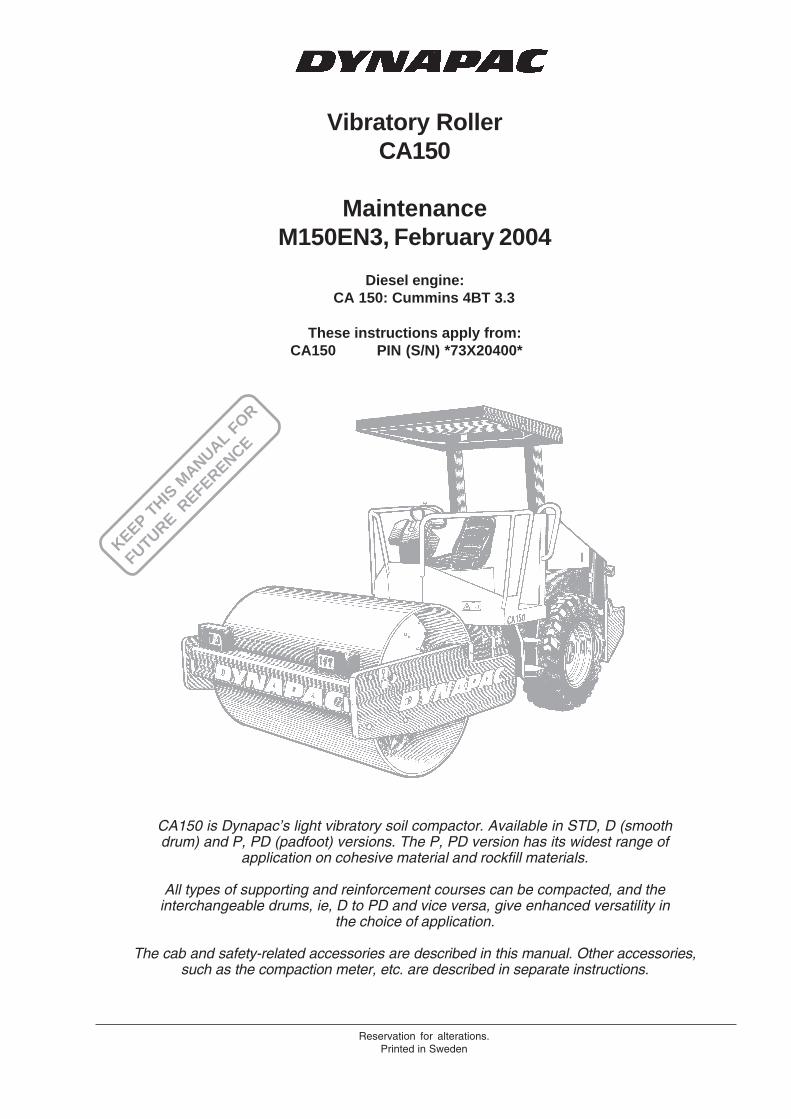
Vibratory RollerCA150
MaintenanceM150EN3, February 2004
Diesel engine:CA 150: Cummins 4BT 3.3
These instructions apply from:CA150 PIN (S/N) *73X20400*
Reservation for alterations.Printed in Sweden
CA150 is Dynapac’s light vibratory soil compactor. Available in STD, D (smoothdrum) and P, PD (padfoot) versions. The P, PD version has its widest range of
application on cohesive material and rockfill materials.
All types of supporting and reinforcement courses can be compacted, and theinterchangeable drums, ie, D to PD and vice versa, give enhanced versatility in
the choice of application.
The cab and safety-related accessories are described in this manual. Other accessories,such as the compaction meter, etc. are described in separate instructions.
KEEP THIS
MANUAL F
OR
FUTURE REFERENCE
2 CA150 M150EN3
It is important that the roller is maintained correctly toensure proper function. It should be kept clean so that anyleakage, loose bolts and loose connections can bediscovered in time.
Make a habit of walking round the roller to check it everyday before starting the first shift – including under themachine. This is often the easiest way of discovering anyleakage.
SPARE A THOUGHT FOR THEENVIRONMENT! Do not let oil, fuel and otherenvironmentally hazardous substances contami-nate the environment.
This manual contains instructions for periodic attentionwhich should normally be carried out by the roller operator.
There are additional instructions relating to thediesel engine, for which the manufacturer’sinstructions are detailed in the engine manual.This is found under a separate flap in the roller’sproduct binder.
CONTENTS
GENERAL
WARNING SYMBOLS
Safety instruction – Personal Safety
Special caution – Machine or component damage
Read through the entire manual beforestarting any maintenance operations.
Ensure good ventilation (air extraction) if thediesel engine is run indoors.
PageLubricants and symbols ................................................... 3Technical specifications ............................................... 4-6Maintenance schedule ..................................................... 7Maintenance Measure .................................................. 8, 9Every 10 operating hours (daily) ...............................10-13Every 50 operating hours (weekly) ...........................14-16Every 250 operating hours (monthly) ........................17-20Every 500 operating hours (every three months) .......... 21Every 1000 operating hours (every six months) .......22-24Every 2000 operating hours (every year) ................ 25, 26Long-term storage .......................................................... 27Special instructions ........................................................ 28Electrical system, fuses ........................................... 29, 30
CALIFORNIA
Proposition 65 Warning
Diesel engine exhaust and some of itsconstituents are known to the State ofCalifornia to cause cancer, birth defects,and other reproductive harm.
3CA150 M150EN3
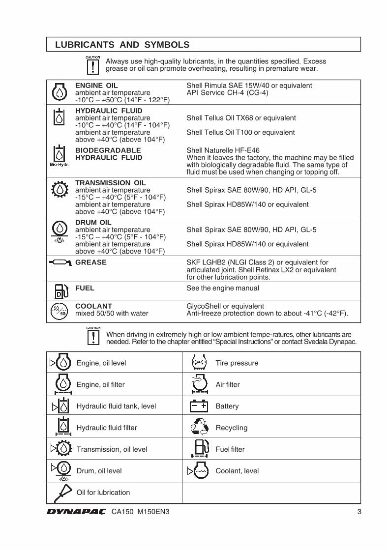
LUBRICANTS AND SYMBOLS
ENGINE OIL Shell Rimula SAE 15W/40 or equivalentambient air temperature API Service CH-4 (CG-4)-10°C – +50°C (14°F - 122°F)
HYDRAULIC FLUIDambient air temperature Shell Tellus Oil TX68 or equivalent-10°C – +40°C (14°F - 104°F)ambient air temperature Shell Tellus Oil T100 or equivalentabove +40°C (above 104°F)
BIODEGRADABLE Shell Naturelle HF-E46HYDRAULIC FLUID When it leaves the factory, the machine may be filled
with biologically degradable fluid. The same type offluid must be used when changing or topping off.
TRANSMISSION OILambient air temperature Shell Spirax SAE 80W/90, HD API, GL-5-15°C – +40°C (5°F - 104°F)ambient air temperature Shell Spirax HD85W/140 or equivalentabove +40°C (above 104°F)
DRUM OILambient air temperature Shell Spirax SAE 80W/90, HD API, GL-5-15°C – +40°C (5°F - 104°F)ambient air temperature Shell Spirax HD85W/140 or equivalentabove +40°C (above 104°F)
GREASE SKF LGHB2 (NLGI Class 2) or equivalent forarticulated joint. Shell Retinax LX2 or equivalentfor other lubrication points.
FUEL See the engine manual
COOLANT GlycoShell or equivalentmixed 50/50 with water Anti-freeze protection down to about -41°C (-42°F).
Always use high-quality lubricants, in the quantities specified. Excessgrease or oil can promote overheating, resulting in premature wear.
When driving in extremely high or low ambient tempe-ratures, other lubricants areneeded. Refer to the chapter entitled “Special Instructions” or contact Svedala Dynapac.
Engine, oil level Tire pressure
Engine, oil filter Air filter
Hydraulic fluid tank, level Battery
Hydraulic fluid filter Recycling
Transmission, oil level Fuel filter
Drum, oil level Coolant, level
Oil for lubrication
4 CA150 M150EN3
TECHNICAL SPECIFICATIONS
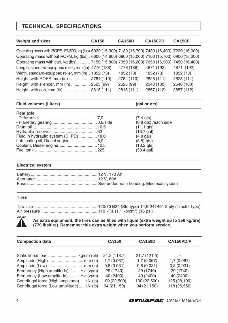
Weight and sizes CA150 CA150D CA150PD CA150P
Operating mass with ROPS, EN500, kg (lbs) 6930 (15,300) 7130 (15,700) 7430 (16,400) 7230 (16,000)Operating mass without ROPS, kg (lbs) . 6600 (14,600) 6800 (15,000) 7100 (15,700) 6900 (15,200)Operating mass with cab, kg (lbs) ........... 7150 (15,800) 7350 (16,200) 7650 (16,900) 7450 (16,400)Length, standard-equipped roller, mm (in) 4776 (188) 4776 (188) 4871 (192) 4871 (192)Width, standard-equipped roller, mm (in) . 1852 (73) 1852 (73) 1852 (73) 1852 (73)Height, with ROPS, mm (in) .................. 2784 (110) 2784 (110) 2825 (111) 2825 (111)Height, with silencer, mm (in) ................ 2525 (99) 2525 (99) 2540 (100) 2540 (100)Height, with cab, mm (in) ....................... 2815 (111) 2815 (111) 2857 (112) 2857 (112)
Fluid volumes (Liters) (gal or qts)
Rear axle:- Differential ................................................. 7,0 (7.4 qts)- Planetary gearing ...................................... 0,8/side (0.8 qts) /each sideDrum oil ....................................................... 10,5 (11.1 qts)Hydraulic reservoir ...................................... 52 (13.7 gal)Fluid in hydraulic system (D, PD) ............... 18,0 (4.8 gal)Lubricating oil, Diesel engine ....................... 8,0 (8.5) qts)Coolant, Diesel engine ................................ 12,5 (13.2 qts)Fuel tank ..................................................... 225 (59.4 gal)
Electrical system
Battery ......................................................... 12 V, 170 AhAlternator ..................................................... 12 V, 60AFuses .......................................................... See under main heading: Electrical system
Tires
Tire size ...................................................... 420/70 B24 (Std type) 14,9-24T461 8 ply (Tractor type)Air pressure ................................................ 110 kPa (1,1 kp/cm2) (16 psi)
As extra equipment, the tires can be filled with liquid (extra weight up to 350 kg/tire)(770 lbs/tire). Remember this extra weight when you perform service.
Compaction data CA150 CA150D CA150PD/P
Static linear load ......................... kg/cm (pli) 21,2 (118.7) 21,7 (121.5) –Amplitude (High) .............................. mm (in) 1,7 (0.067) 1,7 (0.067) 1,7 (0.067)Amplitude (Low) .............................. mm (in) 0,8 (0.031) 0,8 (0.031) 0,8 (0.031)Frequency (High amplitude) ......... Hz (vpm) 29 (1740) 29 (1740) 29 (1740)Frequency (Low amplitude) .......... Hz (vpm) 40 (2400) 40 (2400) 40 (2400)Centrifugal force (High amplitude) .... kN (lb) 100 (22,500) 100 (22,500) 125 (28,100)Centrifugal force (Low amplitude) ..... kN (lb) 94 (21,150) 94 (21,150) 118 (26,550)
5CA150 M150EN3
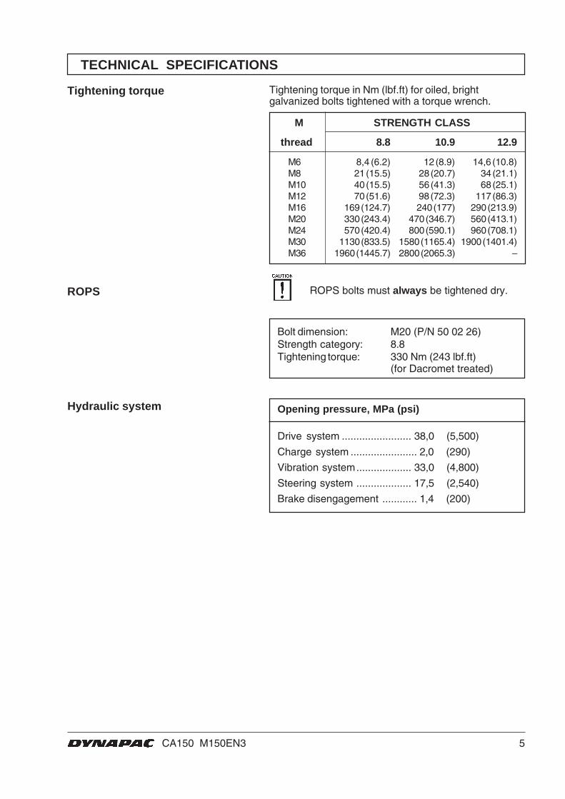
Tightening torque
Hydraulic system
Bolt dimension: M20 (P/N 50 02 26)Strength category: 8.8Tightening torque: 330 Nm (243 lbf.ft)
(for Dacromet treated)
ROPS
Opening pressure, MPa (psi)
Drive system ........................ 38,0 (5,500)
Charge system ....................... 2,0 (290)
Vibration system................... 33,0 (4,800)
Steering system ................... 17,5 (2,540)
Brake disengagement ............ 1,4 (200)
TECHNICAL SPECIFICATIONS
Tightening torque in Nm (lbf.ft) for oiled, brightgalvanized bolts tightened with a torque wrench.
M STRENGTH CLASS
thread 8.8 10.9 12.9
M6 8,4 (6.2) 12 (8.9) 14,6 (10.8)M8 21 (15.5) 28 (20.7) 34 (21.1)M10 40 (15.5) 56 (41.3) 68 (25.1)M12 70 (51.6) 98 (72.3) 117 (86.3)M16 169 (124.7) 240 (177) 290 (213.9)M20 330 (243.4) 470 (346.7) 560 (413.1)M24 570 (420.4) 800 (590.1) 960 (708.1)M30 1130 (833.5) 1580 (1165.4) 1900 (1401.4)M36 1960 (1445.7) 2800 (2065.3) –
ROPS bolts must always be tightened dry.
6 CA150 M150EN3
TECHNICAL SPECIFICATIONS
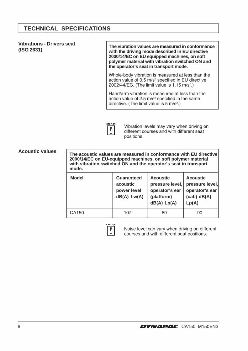
Vibrations - Drivers seat(ISO 2631)
CA150 107 89 90
The acoustic values are measured in conformance with EU directive2000/14/EC on EU-equipped machines, on soft polymer materialwith vibration switched ON and the operator’s seat in transportmode.
Acoustic values
Model Guaranteedacousticpower leveldB(A) Lw(A)
Acousticpressure level,operator’s ear(platform)dB(A) Lp(A)
Acousticpressure level,operator’s ear(cab) dB(A)Lp(A)
Noise level can vary when driving on differentcourses and with different seat positions.
Vibration levels may vary when driving ondifferent courses and with different seatpositions.
The vibration values are measured in conformancewith the driving mode described in EU directive2000/14/EC on EU equipped machines, on softpolymer material with vibration switched ON andthe operator’s seat in transport mode.
Whole-body vibration is measured at less than theaction value of 0.5 m/s2 specified in EU directive2002/44/EC. (The limit value is 1.15 m/s2.)
Hand/arm vibration is measured at less than theaction value of 2.5 m/s2 specified in the samedirective. (The limit value is 5 m/s2.)
7CA150 M150EN3
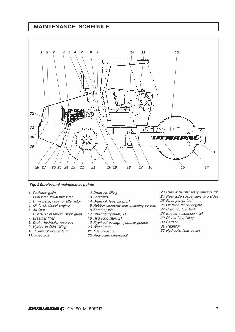
1. Radiator grille2. Fuel filter, initial fuel filter3. Drive belts, cooling, alternator4. Oil level, diesel engine5. Air filter6. Hydraulic reservoir, sight glass7. Breather filter8. Drain, hydraulic reservoir9. Hydraulic fluid, filling10. Forward/reverse lever11. Fuse box
12. Drum oil, filling13. Scrapers14. Drum oil, level plug, x115. Rubber elements and fastening screws16. Steering joint17. Steering cylinder, x118. Hydraulic filter, x119. Flywheel casing, hydraulic pumps20. Wheel nuts21. Tire pressure22. Rear axle, differential
23. Rear axle, planetary gearing, x224. Rear axle suspension, two sides25. Feed pump, fuel26. Oil filter, diesel engine27. Draining, fuel tank28. Engine suspension, x429. Diesel fuel, filling30. Battery31. Radiator32. Hydraulic fluid cooler
MAINTENANCE SCHEDULE
1 2 3 4 5 6 7 8 9 10 11 12
28 27 26 25 24 23 22 21 20 19 18 17 16 15 14
13
32
31
30
29
Fig. 1 Service and maintenance points
8 CA150 M150EN3
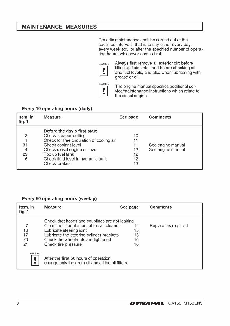
MAINTENANCE MEASURES
Periodic maintenance shall be carried out at thespecified intervals, that is to say either every day,every week etc., or after the specified number of opera-ting hours, whichever comes first.
Always first remove all exterior dirt beforefilling up fluids etc., and before checking oiland fuel levels, and also when lubricating withgrease or oil.
The engine manual specifies additional ser-vice/maintenance instructions which relate tothe diesel engine.
Item. in Measure See page Commentsfig. 1
Before the day’s first start13 Check scraper setting 101 Check for free circulation of cooling air 11
31 Check coolant level 11 See engine manual4 Check diesel engine oil level 12 See engine manual
29 Top up fuel tank 126 Check fluid level in hydraulic tank 12
Check brakes 13
Every 10 operating hours (daily)
Item. in Measure See page Commentsfig. 1
Check that hoses and couplings are not leaking7 Clean the filter element of the air cleaner 14 Replace as required
16 Lubricate steering joint 1517 Lubricate the steering cylinder brackets 1520 Check the wheel-nuts are tightened 1621 Check tire pressure 16
After the first 50 hours of operation,change only the drum oil and all the oil filters.
Every 50 operating hours (weekly)
CAUTION
CAUTION
CAUTION
9CA150 M150EN3
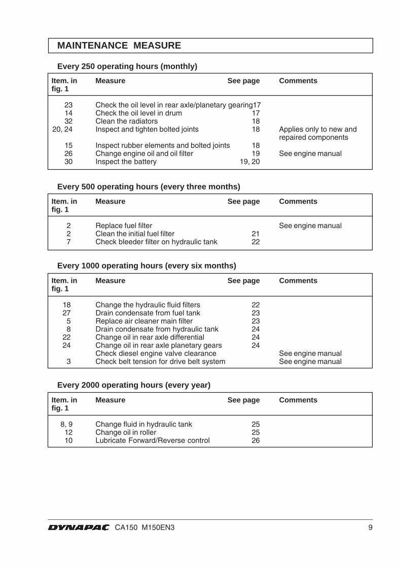
MAINTENANCE MEASURE
Item. in Measure See page Commentsfig. 1
23 Check the oil level in rear axle/planetary gearing1714 Check the oil level in drum 1732 Clean the radiators 18
20, 24 Inspect and tighten bolted joints 18 Applies only to new andrepaired components
15 Inspect rubber elements and bolted joints 1826 Change engine oil and oil filter 19 See engine manual30 Inspect the battery 19, 20
Every 250 operating hours (monthly)
Item. in Measure See page Commentsfig. 1
18 Change the hydraulic fluid filters 2227 Drain condensate from fuel tank 235 Replace air cleaner main filter 238 Drain condensate from hydraulic tank 24
22 Change oil in rear axle differential 2424 Change oil in rear axle planetary gears 24
Check diesel engine valve clearance See engine manual3 Check belt tension for drive belt system See engine manual
Every 1000 operating hours (every six months)
Item. in Measure See page Commentsfig. 1
8, 9 Change fluid in hydraulic tank 2512 Change oil in roller 2510 Lubricate Forward/Reverse control 26
Every 2000 operating hours (every year)
Item. in Measure See page Commentsfig. 1
2 Replace fuel filter See engine manual2 Clean the initial fuel filter 217 Check bleeder filter on hydraulic tank 22
Every 500 operating hours (every three months)
10 CA150 M150EN3
EVERY 10 OPERATING HOURS (Daily)
1
2
2 1 1 2
1
2
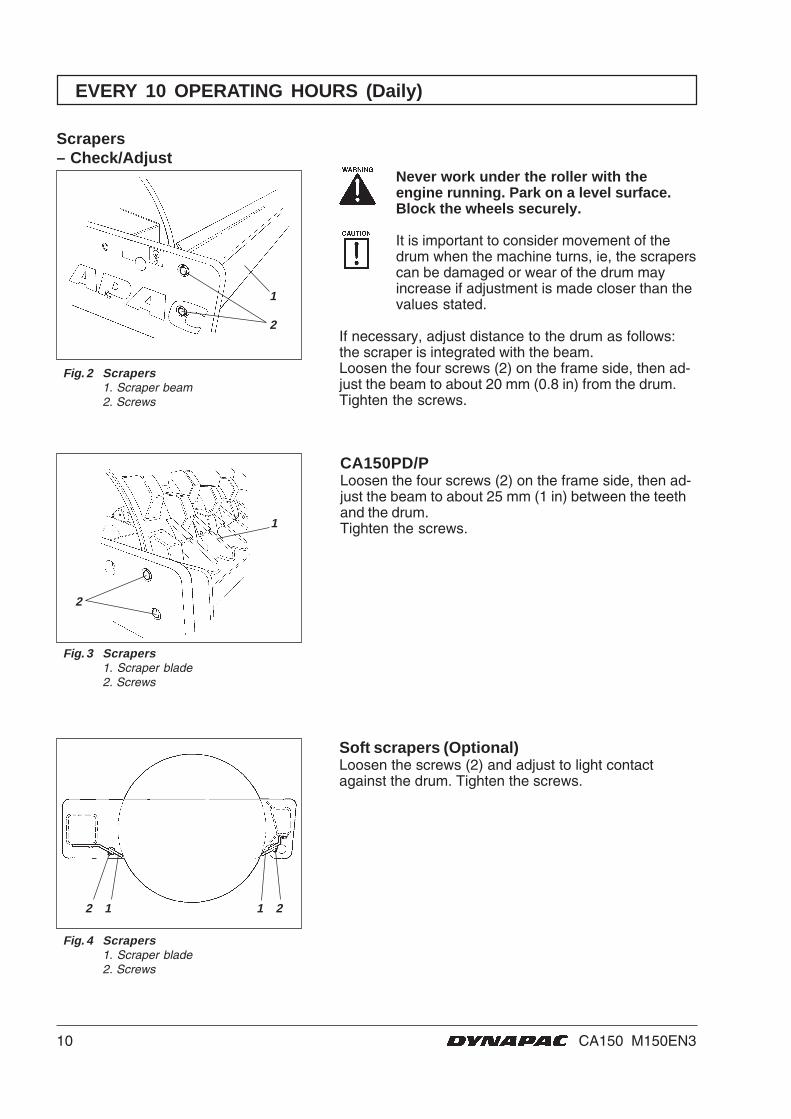
Never work under the roller with theengine running. Park on a level surface.Block the wheels securely.
It is important to consider movement of thedrum when the machine turns, ie, the scraperscan be damaged or wear of the drum mayincrease if adjustment is made closer than thevalues stated.
If necessary, adjust distance to the drum as follows:the scraper is integrated with the beam.Loosen the four screws (2) on the frame side, then ad-just the beam to about 20 mm (0.8 in) from the drum.Tighten the screws.
Scrapers– Check/Adjust
Fig. 2 Scrapers1. Scraper beam2. Screws
Soft scrapers (Optional)Loosen the screws (2) and adjust to light contactagainst the drum. Tighten the screws.
Fig. 4 Scrapers1. Scraper blade2. Screws
Fig. 3 Scrapers1. Scraper blade2. Screws
CA150PD/PLoosen the four screws (2) on the frame side, then ad-just the beam to about 25 mm (1 in) between the teethand the drum.Tighten the screws.
11CA150 M150EN3
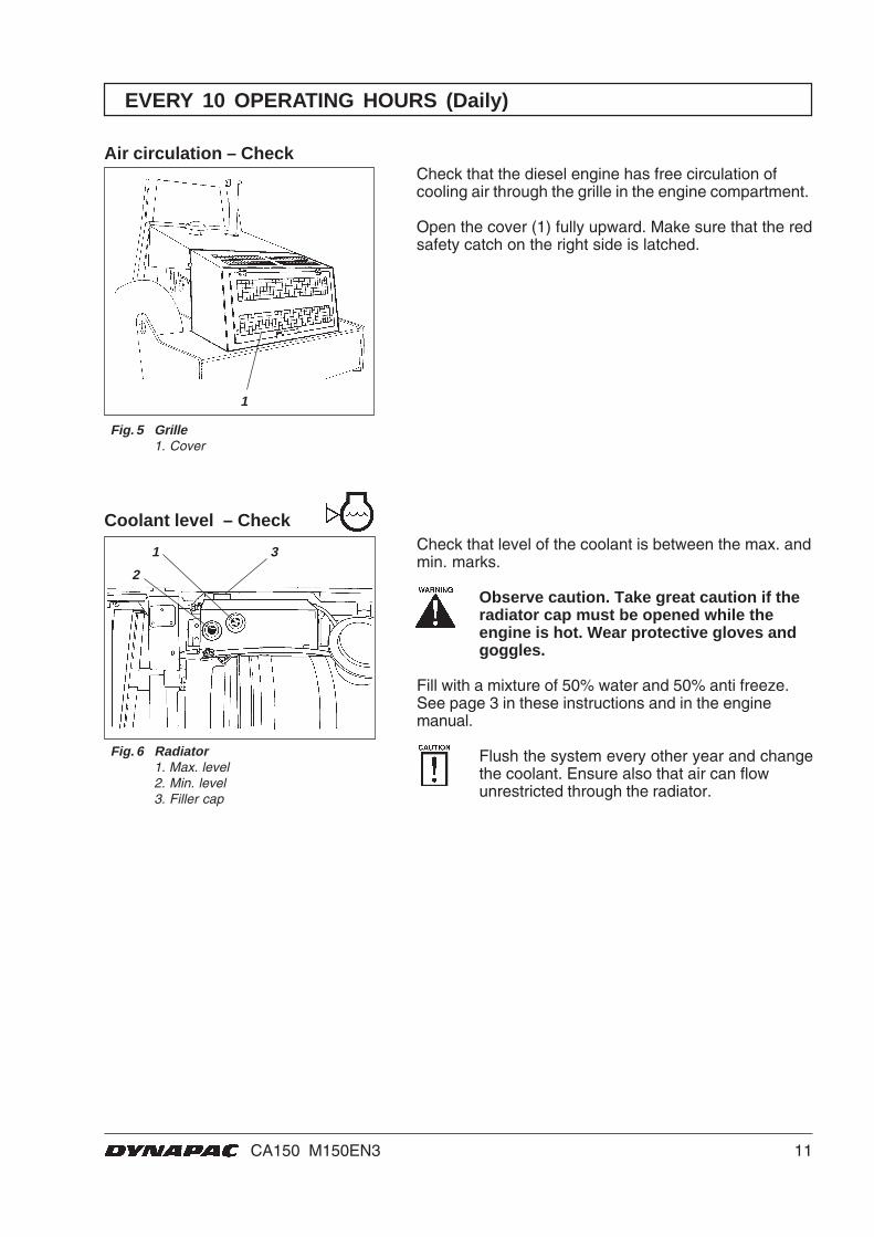
Check that the diesel engine has free circulation ofcooling air through the grille in the engine compartment.
Open the cover (1) fully upward. Make sure that the redsafety catch on the right side is latched.
Air circulation – Check
Fig. 5 Grille1. Cover
1
EVERY 10 OPERATING HOURS (Daily)
Fig. 6 Radiator1. Max. level2. Min. level3. Filler cap
Check that level of the coolant is between the max. andmin. marks.
Observe caution. Take great caution if theradiator cap must be opened while theengine is hot. Wear protective gloves andgoggles.
Fill with a mixture of 50% water and 50% anti freeze.See page 3 in these instructions and in the enginemanual.
Flush the system every other year and changethe coolant. Ensure also that air can flowunrestricted through the radiator.
1 3
2
Coolant level – Check
12 CA150 M150EN3
1
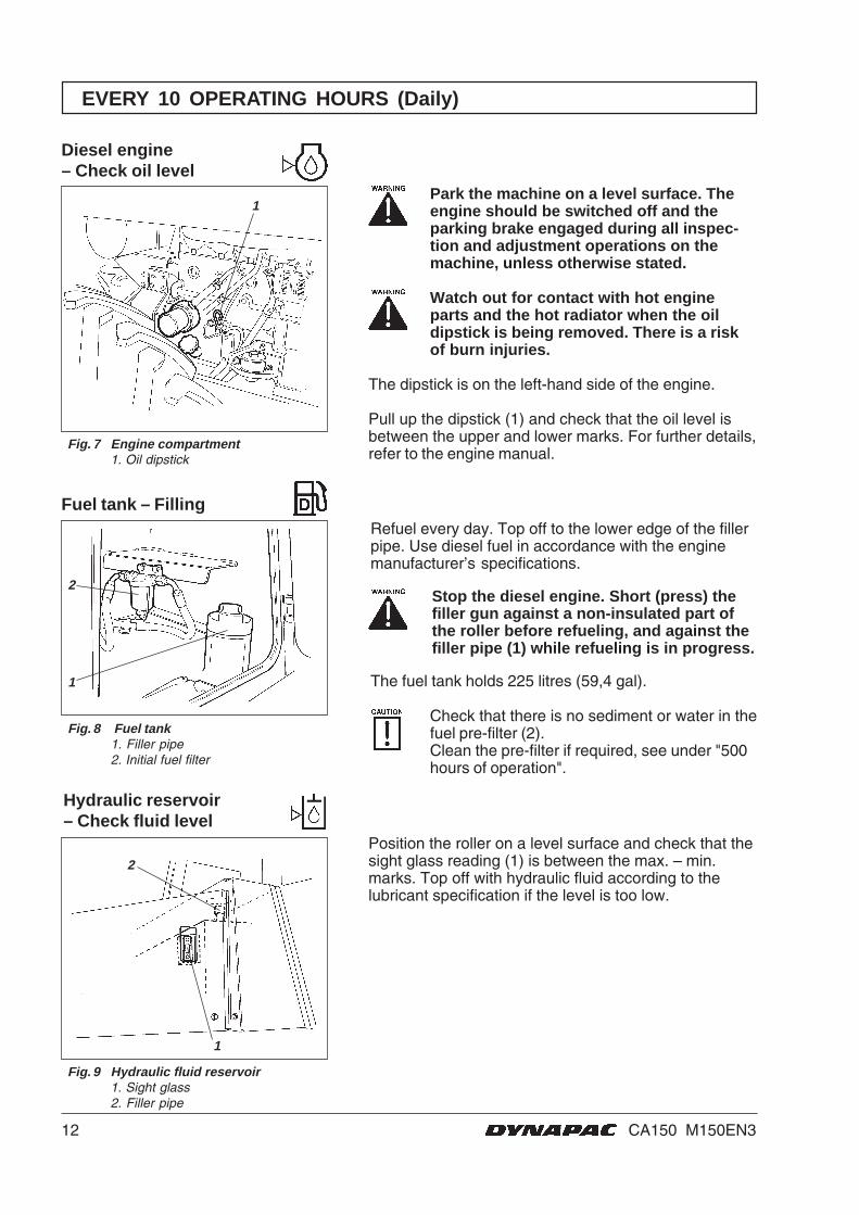
Fig. 8 Fuel tank1. Filler pipe2. Initial fuel filter
2
1
Fig. 9 Hydraulic fluid reservoir1. Sight glass2. Filler pipe
Position the roller on a level surface and check that thesight glass reading (1) is between the max. – min.marks. Top off with hydraulic fluid according to thelubricant specification if the level is too low.
2
1
EVERY 10 OPERATING HOURS (Daily)
Park the machine on a level surface. Theengine should be switched off and theparking brake engaged during all inspec-tion and adjustment operations on themachine, unless otherwise stated.
Watch out for contact with hot engineparts and the hot radiator when the oildipstick is being removed. There is a riskof burn injuries.
The dipstick is on the left-hand side of the engine.
Pull up the dipstick (1) and check that the oil level isbetween the upper and lower marks. For further details,refer to the engine manual.
Fig. 7 Engine compartment1. Oil dipstick
Diesel engine– Check oil level
Fuel tank – FillingRefuel every day. Top off to the lower edge of the fillerpipe. Use diesel fuel in accordance with the enginemanufacturer’s specifications.
Stop the diesel engine. Short (press) thefiller gun against a non-insulated part ofthe roller before refueling, and against thefiller pipe (1) while refueling is in progress.
The fuel tank holds 225 litres (59,4 gal).
Check that there is no sediment or water in thefuel pre-filter (2).Clean the pre-filter if required, see under "500hours of operation".
Hydraulic reservoir– Check fluid level
13CA150 M150EN3
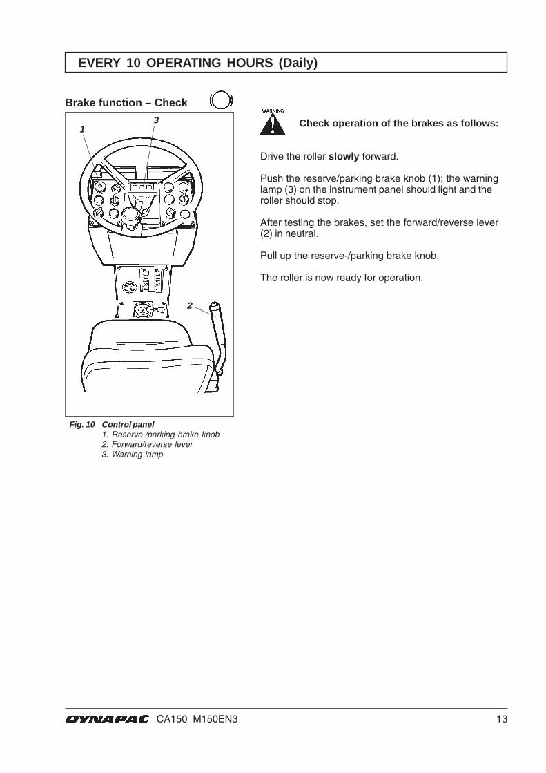
Fig. 10 Control panel1. Reserve-/parking brake knob2. Forward/reverse lever3. Warning lamp
13
2
EVERY 10 OPERATING HOURS (Daily)
Check operation of the brakes as follows:
Drive the roller slowly forward.
Push the reserve/parking brake knob (1); the warninglamp (3) on the instrument panel should light and theroller should stop.
After testing the brakes, set the forward/reverse lever(2) in neutral.
Pull up the reserve-/parking brake knob.
The roller is now ready for operation.
Brake function – Check
14 CA150 M150EN3
EVERY 50 OPERATING HOURS (Weekly)
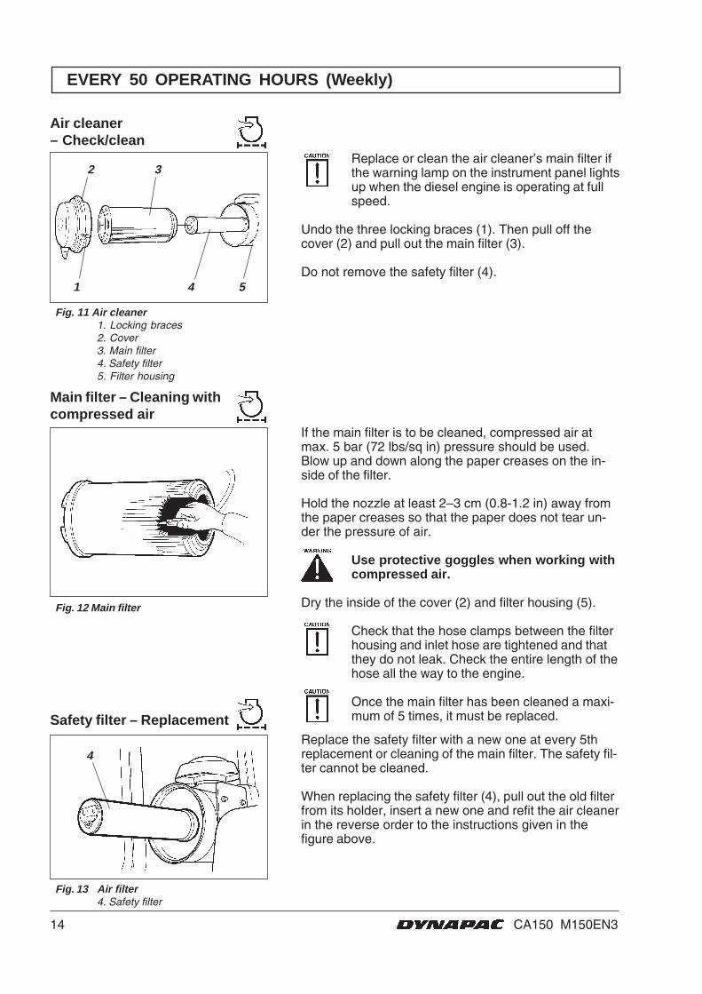
Replace or clean the air cleaner’s main filter ifthe warning lamp on the instrument panel lightsup when the diesel engine is operating at fullspeed.
Undo the three locking braces (1). Then pull off thecover (2) and pull out the main filter (3).
Do not remove the safety filter (4).
If the main filter is to be cleaned, compressed air atmax. 5 bar (72 lbs/sq in) pressure should be used.Blow up and down along the paper creases on the in-side of the filter.
Hold the nozzle at least 2–3 cm (0.8-1.2 in) away fromthe paper creases so that the paper does not tear un-der the pressure of air.
Use protective goggles when working withcompressed air.
Dry the inside of the cover (2) and filter housing (5).
Check that the hose clamps between the filterhousing and inlet hose are tightened and thatthey do not leak. Check the entire length of thehose all the way to the engine.
Once the main filter has been cleaned a maxi-mum of 5 times, it must be replaced.
Main filter – Cleaning withcompressed air
Fig. 12 Main filter
2 3
Fig. 11 Air cleaner1. Locking braces2. Cover3. Main filter4. Safety filter5. Filter housing
1 4 5
Air cleaner– Check/clean
Fig. 13 Air filter4. Safety filter
Safety filter – Replacement
4Replace the safety filter with a new one at every 5threplacement or cleaning of the main filter. The safety fil-ter cannot be cleaned.
When replacing the safety filter (4), pull out the old filterfrom its holder, insert a new one and refit the air cleanerin the reverse order to the instructions given in thefigure above.
15CA150 M150EN3
EVERY 50 OPERATING HOURS (Weekly)
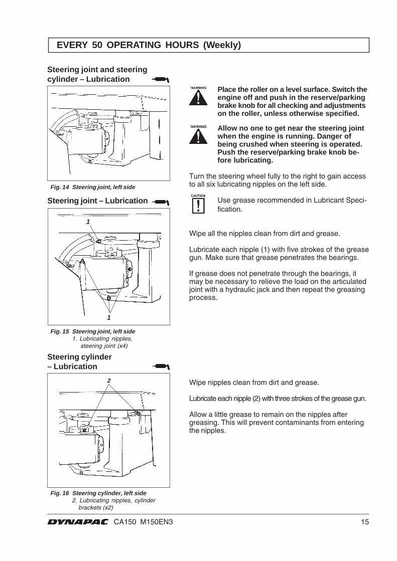
Steering joint and steeringcylinder – Lubrication
Fig. 14 Steering joint, left side
Place the roller on a level surface. Switch theengine off and push in the reserve/parkingbrake knob for all checking and adjustmentson the roller, unless otherwise specified.
Allow no one to get near the steering jointwhen the engine is running. Danger ofbeing crushed when steering is operated.Push the reserve/parking brake knob be-fore lubricating.
Turn the steering wheel fully to the right to gain accessto all six lubricating nipples on the left side.
Use grease recommended in Lubricant Speci-fication.
Wipe all the nipples clean from dirt and grease.
Lubricate each nipple (1) with five strokes of the greasegun. Make sure that grease penetrates the bearings.
If grease does not penetrate through the bearings, itmay be necessary to relieve the load on the articulatedjoint with a hydraulic jack and then repeat the greasingprocess.
Steering joint – Lubrication
Steering cylinder– Lubrication
Fig. 16 Steering cylinder, left side2. Lubricating nipples, cylinder brackets (x2)
Fig. 15 Steering joint, left side1. Lubricating nipples,
steering joint (x4)
Wipe nipples clean from dirt and grease.
Lubricate each nipple (2) with three strokes of the grease gun.
Allow a little grease to remain on the nipples aftergreasing. This will prevent contaminants from enteringthe nipples.
1
1
2
16 CA150 M150EN3
EVERY 50 OPERATING HOURS (Weekly)
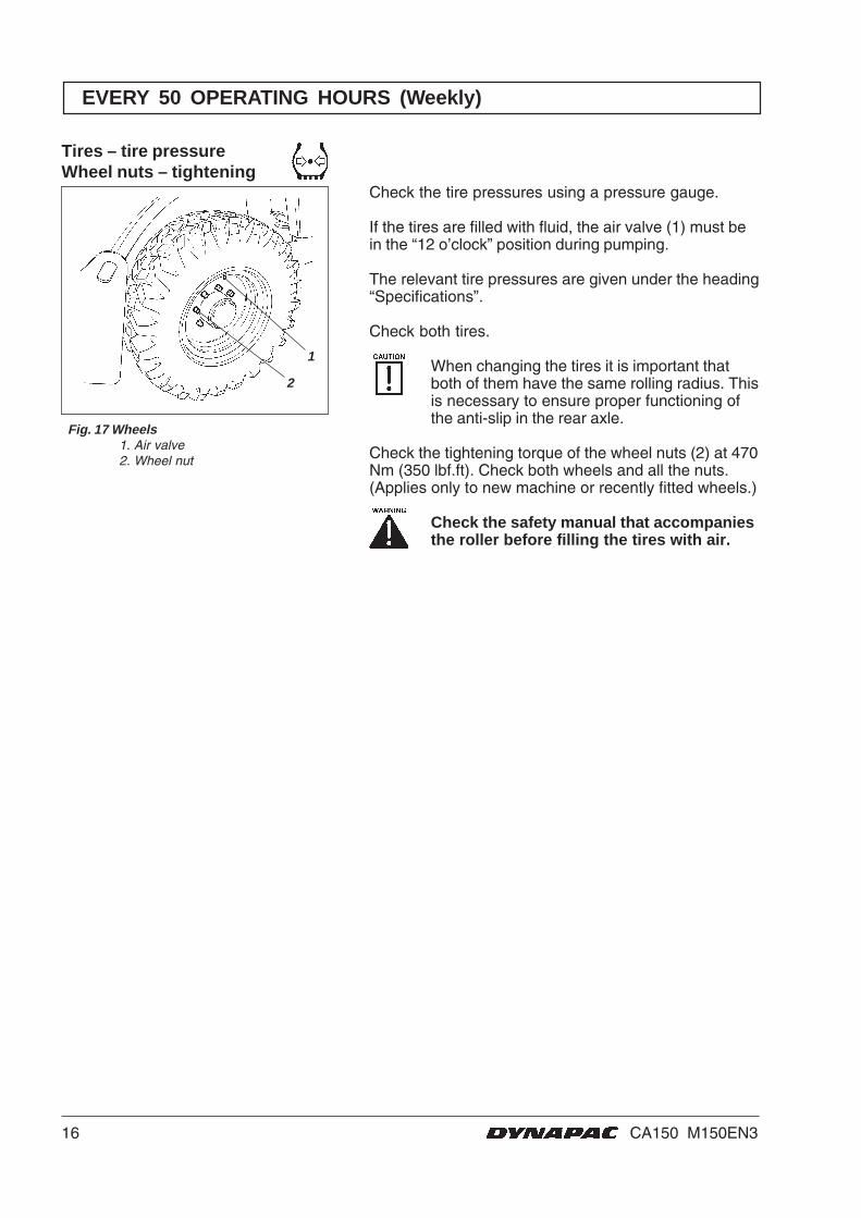
Tires – tire pressureWheel nuts – tightening
Fig. 17 Wheels1. Air valve2. Wheel nut
1
2
Check the tire pressures using a pressure gauge.
If the tires are filled with fluid, the air valve (1) must bein the “12 o’clock” position during pumping.
The relevant tire pressures are given under the heading“Specifications”.
Check both tires.
When changing the tires it is important thatboth of them have the same rolling radius. Thisis necessary to ensure proper functioning ofthe anti-slip in the rear axle.
Check the tightening torque of the wheel nuts (2) at 470Nm (350 lbf.ft). Check both wheels and all the nuts.(Applies only to new machine or recently fitted wheels.)
Check the safety manual that accompaniesthe roller before filling the tires with air.
17CA150 M150EN3
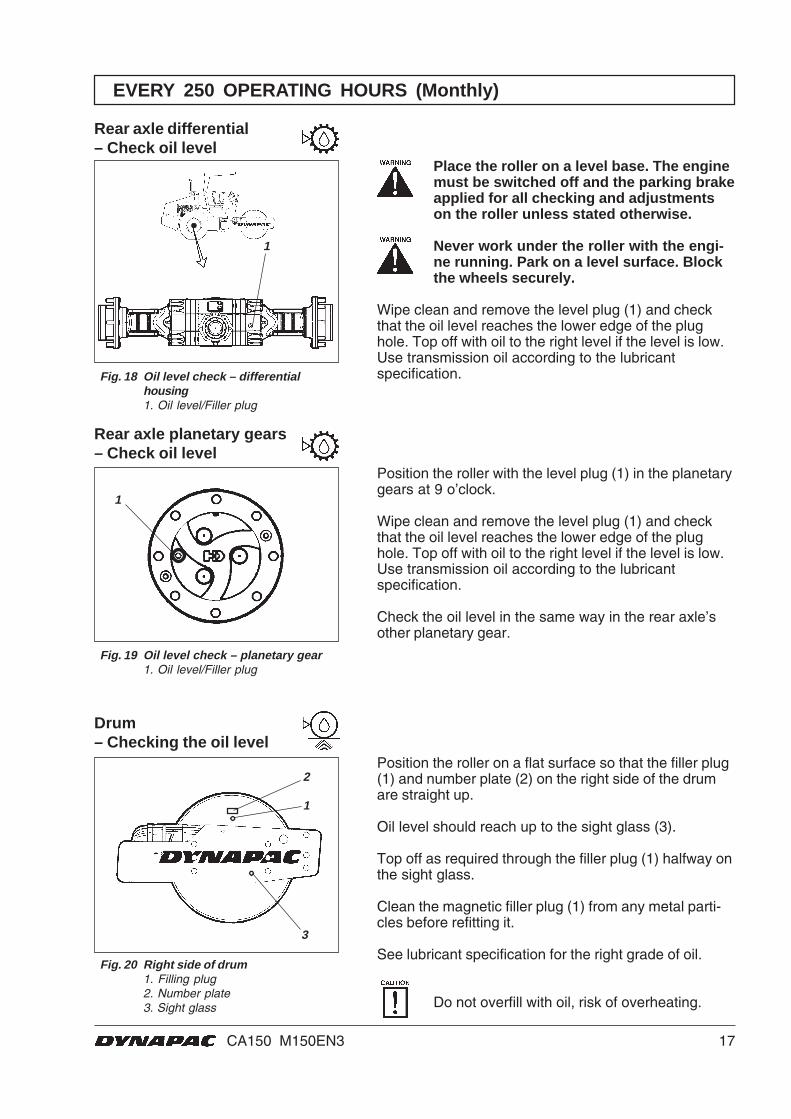
Rear axle differential– Check oil level
Fig. 18 Oil level check – differentialhousing1. Oil level/Filler plug
Rear axle planetary gears– Check oil level
Fig. 19 Oil level check – planetary gear1. Oil level/Filler plug
Fig. 20 Right side of drum1. Filling plug2. Number plate3. Sight glass
Position the roller on a flat surface so that the filler plug(1) and number plate (2) on the right side of the drumare straight up.
Oil level should reach up to the sight glass (3).
Top off as required through the filler plug (1) halfway onthe sight glass.
Clean the magnetic filler plug (1) from any metal parti-cles before refitting it.
See lubricant specification for the right grade of oil.
Do not overfill with oil, risk of overheating.
Drum– Checking the oil level
1
3
2
1
1
Place the roller on a level base. The enginemust be switched off and the parking brakeapplied for all checking and adjustmentson the roller unless stated otherwise.
Never work under the roller with the engi-ne running. Park on a level surface. Blockthe wheels securely.
Wipe clean and remove the level plug (1) and checkthat the oil level reaches the lower edge of the plughole. Top off with oil to the right level if the level is low.Use transmission oil according to the lubricantspecification.
Position the roller with the level plug (1) in the planetarygears at 9 o’clock.
Wipe clean and remove the level plug (1) and checkthat the oil level reaches the lower edge of the plughole. Top off with oil to the right level if the level is low.Use transmission oil according to the lubricantspecification.
Check the oil level in the same way in the rear axle’sother planetary gear.
EVERY 250 OPERATING HOURS (Monthly)
18 CA150 M150EN3
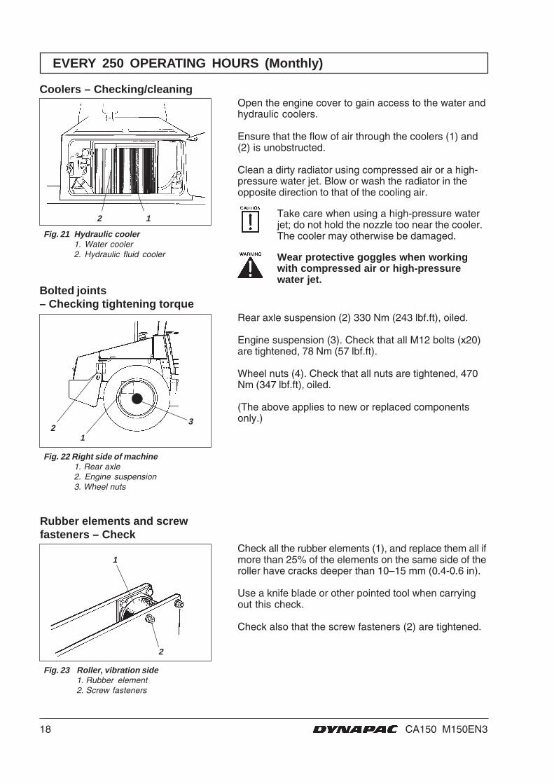
Open the engine cover to gain access to the water andhydraulic coolers.
Ensure that the flow of air through the coolers (1) and(2) is unobstructed.
Clean a dirty radiator using compressed air or a high-pressure water jet. Blow or wash the radiator in theopposite direction to that of the cooling air.
Take care when using a high-pressure waterjet; do not hold the nozzle too near the cooler.The cooler may otherwise be damaged.
Wear protective goggles when workingwith compressed air or high-pressurewater jet.
Fig. 21 Hydraulic cooler1. Water cooler2. Hydraulic fluid cooler
Coolers – Checking/cleaning
2 1
Bolted joints– Checking tightening torque
Fig. 22 Right side of machine1. Rear axle2. Engine suspension3. Wheel nuts
Rear axle suspension (2) 330 Nm (243 lbf.ft), oiled.
Engine suspension (3). Check that all M12 bolts (x20)are tightened, 78 Nm (57 lbf.ft).
Wheel nuts (4). Check that all nuts are tightened, 470Nm (347 lbf.ft), oiled.
(The above applies to new or replaced componentsonly.)
Check all the rubber elements (1), and replace them all ifmore than 25% of the elements on the same side of theroller have cracks deeper than 10–15 mm (0.4-0.6 in).
Use a knife blade or other pointed tool when carryingout this check.
Check also that the screw fasteners (2) are tightened.
Fig. 23 Roller, vibration side1. Rubber element2. Screw fasteners
1
2
21
3
EVERY 250 OPERATING HOURS (Monthly)
Rubber elements and screwfasteners – Check
19CA150 M150EN3
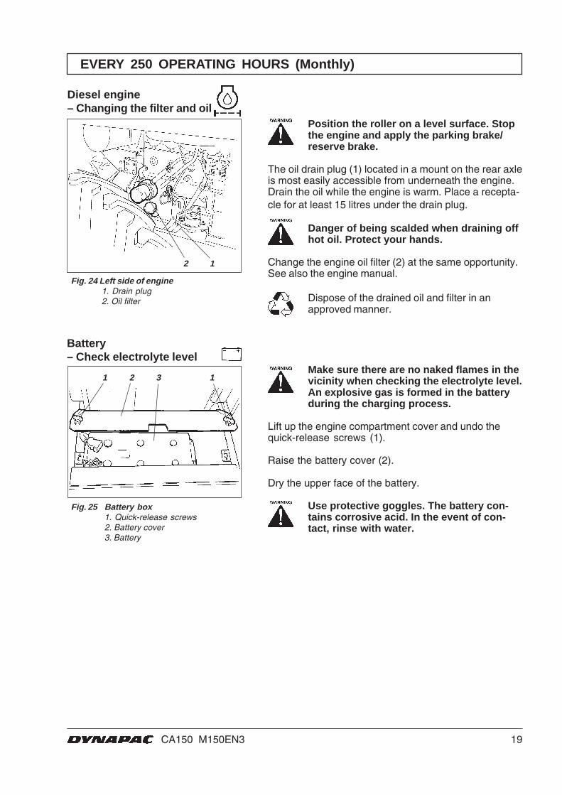
Fig. 24 Left side of engine1. Drain plug2. Oil filter
Diesel engine– Changing the filter and oil
1 2 3 1Make sure there are no naked flames in thevicinity when checking the electrolyte level.An explosive gas is formed in the batteryduring the charging process.
Lift up the engine compartment cover and undo thequick-release screws (1).
Raise the battery cover (2).
Dry the upper face of the battery.
Use protective goggles. The battery con-tains corrosive acid. In the event of con-tact, rinse with water.
12
EVERY 250 OPERATING HOURS (Monthly)
Position the roller on a level surface. Stopthe engine and apply the parking brake/reserve brake.
The oil drain plug (1) located in a mount on the rear axleis most easily accessible from underneath the engine.Drain the oil while the engine is warm. Place a recepta-cle for at least 15 litres under the drain plug.
Danger of being scalded when draining offhot oil. Protect your hands.
Change the engine oil filter (2) at the same opportunity.See also the engine manual.
Dispose of the drained oil and filter in anapproved manner.
Battery– Check electrolyte level
Fig. 25 Battery box1. Quick-release screws2. Battery cover3. Battery
20 CA150 M150EN3
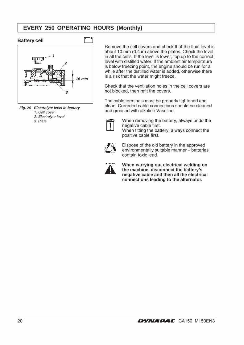
Remove the cell covers and check that the fluid level isabout 10 mm (0.4 in) above the plates. Check the levelin all the cells. If the level is lower, top up to the correctlevel with distilled water. If the ambient air temperatureis below freezing point, the engine should be run for awhile after the distilled water is added, otherwise thereis a risk that the water might freeze.
Check that the ventilation holes in the cell covers arenot blocked, then refit the covers.
The cable terminals must be properly tightened andclean. Corroded cable connections should be cleanedand greased with alkaline Vaseline.
When removing the battery, always undo thenegative cable first.When fitting the battery, always connect thepositive cable first.
Dispose of the old battery in the approvedenvironmentally suitable manner – batteriescontain toxic lead.
When carrying out electrical welding onthe machine, disconnect the battery’snegative cable and then all the electricalconnections leading to the alternator.
1
2
3
10 mm
EVERY 250 OPERATING HOURS (Monthly)
Fig. 26 Electrolyte level in battery1. Cell cover2. Electrolyte level3. Plate
Battery cell
21CA150 M150EN3
EVERY 500 OPERATING HOURS (Every three months)
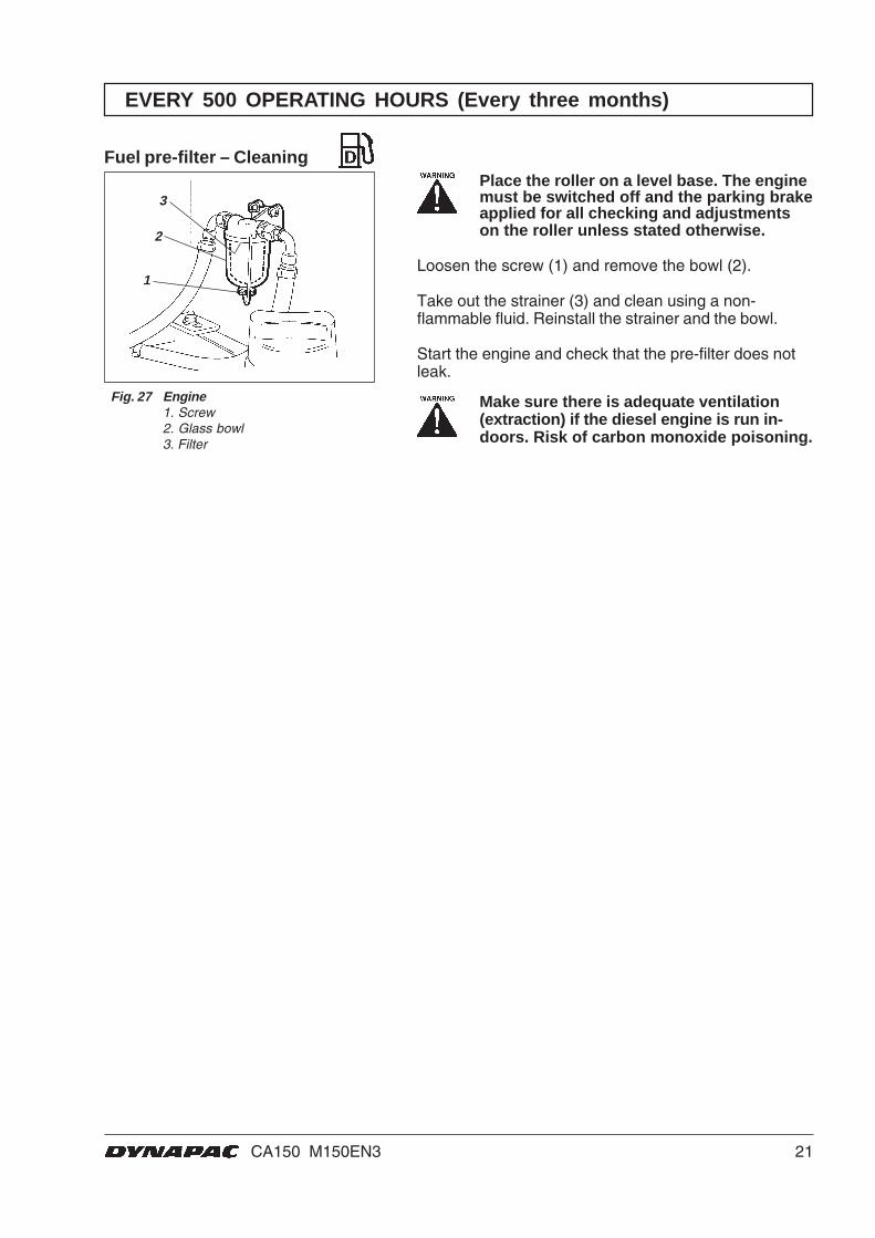
Fig. 27 Engine1. Screw2. Glass bowl3. Filter
Fuel pre-filter – CleaningPlace the roller on a level base. The enginemust be switched off and the parking brakeapplied for all checking and adjustmentson the roller unless stated otherwise.
Loosen the screw (1) and remove the bowl (2).
Take out the strainer (3) and clean using a non-flammable fluid. Reinstall the strainer and the bowl.
Start the engine and check that the pre-filter does notleak.
Make sure there is adequate ventilation(extraction) if the diesel engine is run in-doors. Risk of carbon monoxide poisoning.
2
1
3
22 CA150 M150EN3
3
2
1
EVERY 1000 OPERATING HOURS (Every six months)
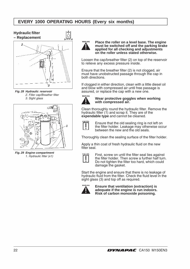
Fig. 28 Hydraulic reservoir2. Filler cap/Breather filter3. Sight glass
Hydraulic filter– Replacement
Fig. 29 Engine compartment1. Hydraulic filter (x1)
Place the roller on a level base. The enginemust be switched off and the parking brakeapplied for all checking and adjustmentson the roller unless stated otherwise.
Loosen the cap/breather filter (2) on top of the reservoirto relieve any excess pressure inside.
Ensure that the breather filter (2) is not clogged, airmust have unobstructed passage through the cap inboth directions.
If clogged in either direction, clean with a little diesel oiland blow with compressed air until free passage isassured, or replace the cap with a new one.
Wear protective goggles when workingwith compressed air.
Clean thoroughly round the hydraulic filter. Remove thehydraulic filter (1) and scrap it. They are of theexpendable type and cannot be cleaned.
Ensure that the old sealing ring is not left onthe filter holder. Leakage may otherwise occurbetween the new and the old seals.
Thoroughly clean the sealing surface of the filter holder.
Apply a thin coat of fresh hydraulic fluid on the newfilter seal.
First, screw on until the filter seal lies againstthe filter holder. Then screw a further half turn.Do not tighten the filter too hard, which coulddamage the gasket.
Start the engine and ensure that there is no leakage ofhydraulic fluid from the filter. Check the fluid level in thesight glass (3) and top off as required.
Ensure that ventilation (extraction) isadequate if the engine is run indoors.Risk of carbon monoxide poisoning.
23CA150 M150EN3
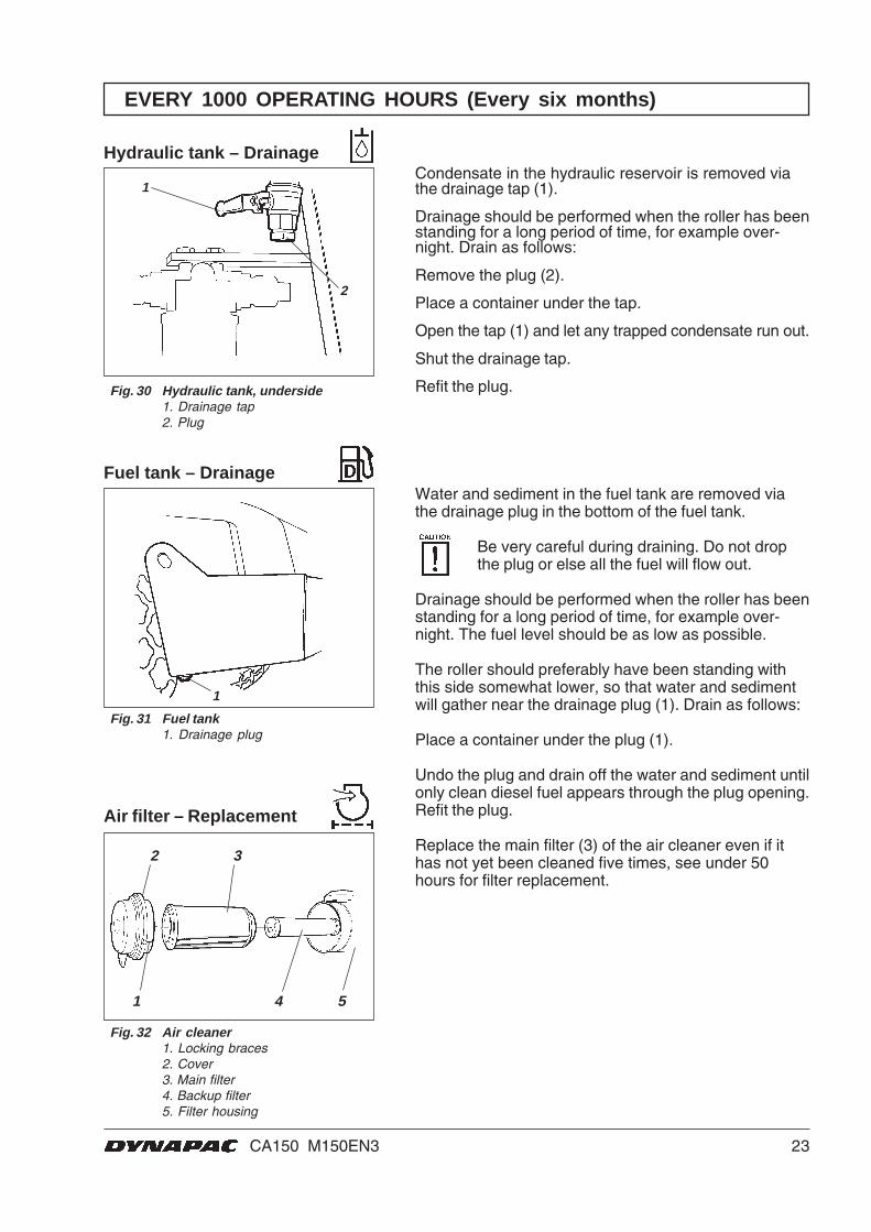
Water and sediment in the fuel tank are removed viathe drainage plug in the bottom of the fuel tank.
Be very careful during draining. Do not dropthe plug or else all the fuel will flow out.
Drainage should be performed when the roller has beenstanding for a long period of time, for example over-night. The fuel level should be as low as possible.
The roller should preferably have been standing withthis side somewhat lower, so that water and sedimentwill gather near the drainage plug (1). Drain as follows:
Place a container under the plug (1).
Undo the plug and drain off the water and sediment untilonly clean diesel fuel appears through the plug opening.Refit the plug.
Replace the main filter (3) of the air cleaner even if ithas not yet been cleaned five times, see under 50hours for filter replacement.
Condensate in the hydraulic reservoir is removed viathe drainage tap (1).
Drainage should be performed when the roller has beenstanding for a long period of time, for example over-night. Drain as follows:
Remove the plug (2).
Place a container under the tap.
Open the tap (1) and let any trapped condensate run out.
Shut the drainage tap.
Refit the plug.
1
2 3
1 4 5
1
2
EVERY 1000 OPERATING HOURS (Every six months)
Fig. 30 Hydraulic tank, underside1. Drainage tap2. Plug
Hydraulic tank – Drainage
Fig. 31 Fuel tank1. Drainage plug
Fuel tank – Drainage
Fig. 32 Air cleaner1. Locking braces2. Cover3. Main filter4. Backup filter5. Filter housing
Air filter – Replacement
24 CA150 M150EN3
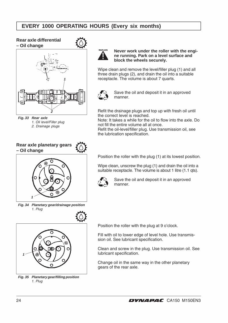
Never work under the roller with the engi-ne running. Park on a level surface andblock the wheels securely.
Wipe clean and remove the level/filler plug (1) and allthree drain plugs (2), and drain the oil into a suitablereceptacle. The volume is about 7 quarts.
Save the oil and deposit it in an approvedmanner.
Refit the drainage plugs and top up with fresh oil untilthe correct level is reached.Note: It takes a while for the oil to flow into the axle. Donot fill the entire volume all at once.Refit the oil-level/filler plug. Use transmission oil, seethe lubrication specification.
1
1
1
2
EVERY 1000 OPERATING HOURS (Every six months)
Fig. 33 Rear axle1. Oil level/Filler plug2. Drainage plugs
Rear axle differential– Oil change
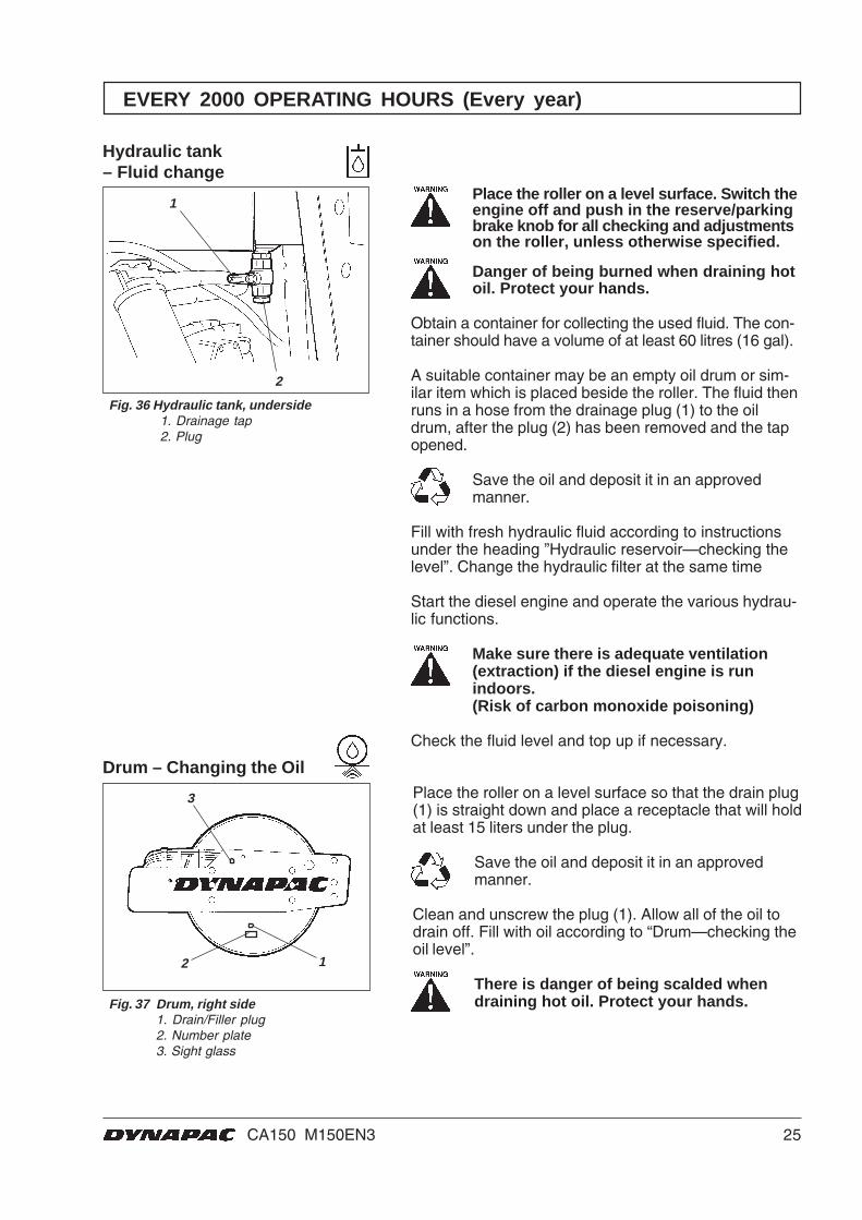
Position the roller with the plug (1) at its lowest position.
Wipe clean, unscrew the plug (1) and drain the oil into asuitable receptacle. The volume is about 1 litre (1.1 qts).
Save the oil and deposit it in an approvedmanner.
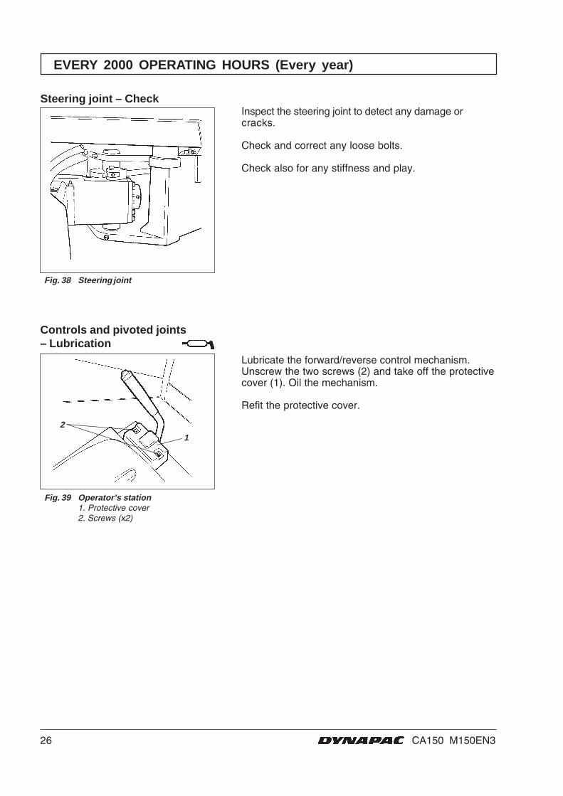
Position the roller with the plug at 9 o’clock.
Fill with oil to lower edge of level hole. Use transmis-sion oil. See lubricant specification.
Clean and screw in the plug. Use transmission oil. Seelubricant specification.
Change oil in the same way in the other planetarygears of the rear axle.
Fig. 35 Planetary gear/filling position1. Plug
Rear axle planetary gears– Oil change
Fig. 34 Planetary gear/drainage position1. Plug
25CA150 M150EN3
1
2
3
12
EVERY 2000 OPERATING HOURS (Every year)
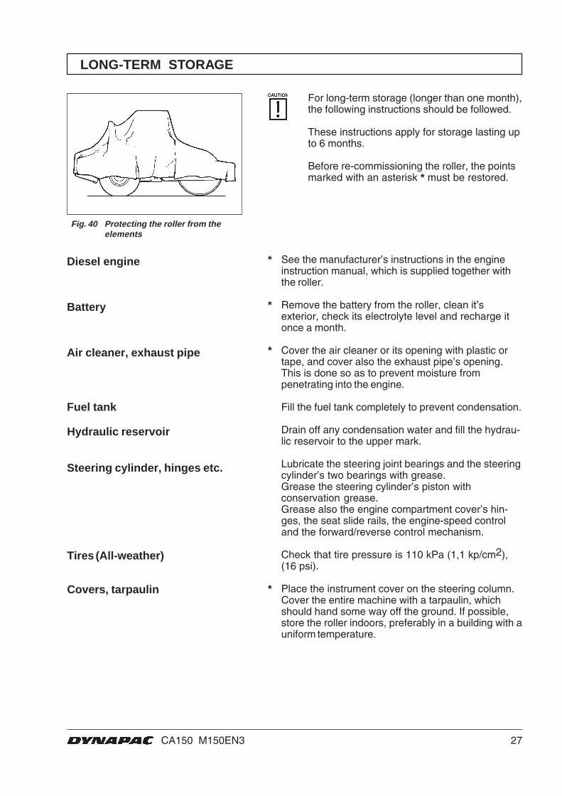
Hydraulic tank– Fluid change
Fig. 36 Hydraulic tank, underside1. Drainage tap2. Plug
Place the roller on a level surface. Switch theengine off and push in the reserve/parkingbrake knob for all checking and adjustmentson the roller, unless otherwise specified.
Danger of being burned when draining hotoil. Protect your hands.
Obtain a container for collecting the used fluid. The con-tainer should have a volume of at least 60 litres (16 gal).
A suitable container may be an empty oil drum or sim-ilar item which is placed beside the roller. The fluid thenruns in a hose from the drainage plug (1) to the oildrum, after the plug (2) has been removed and the tapopened.
Save the oil and deposit it in an approvedmanner.
Fill with fresh hydraulic fluid according to instructionsunder the heading ”Hydraulic reservoir—checking thelevel”. Change the hydraulic filter at the same time
Start the diesel engine and operate the various hydrau-lic functions.
Make sure there is adequate ventilation(extraction) if the diesel engine is runindoors.(Risk of carbon monoxide poisoning)
Check the fluid level and top up if necessary.
Drum – Changing the OilPlace the roller on a level surface so that the drain plug(1) is straight down and place a receptacle that will holdat least 15 liters under the plug.
Save the oil and deposit it in an approvedmanner.
Clean and unscrew the plug (1). Allow all of the oil todrain off. Fill with oil according to “Drum—checking theoil level”.
There is danger of being scalded whendraining hot oil. Protect your hands.Fig. 37 Drum, right side
1. Drain/Filler plug2. Number plate3. Sight glass
26 CA150 M150EN3
Inspect the steering joint to detect any damage orcracks.
Check and correct any loose bolts.
Check also for any stiffness and play.
Fig. 39 Operator’s station1. Protective cover2. Screws (x2)
Controls and pivoted joints– Lubrication
2
Lubricate the forward/reverse control mechanism.Unscrew the two screws (2) and take off the protectivecover (1). Oil the mechanism.
Refit the protective cover.
1
EVERY 2000 OPERATING HOURS (Every year)
Steering joint – Check
Fig. 38 Steering joint
27CA150 M150EN3
LONG-TERM STORAGE
For long-term storage (longer than one month),the following instructions should be followed.
These instructions apply for storage lasting upto 6 months.
Before re-commissioning the roller, the pointsmarked with an asterisk * must be restored.
Fig. 40 Protecting the roller from theelements
* See the manufacturer’s instructions in the engineinstruction manual, which is supplied together withthe roller.
* Remove the battery from the roller, clean it’sexterior, check its electrolyte level and recharge itonce a month.
* Cover the air cleaner or its opening with plastic ortape, and cover also the exhaust pipe’s opening.This is done so as to prevent moisture frompenetrating into the engine.
Fill the fuel tank completely to prevent condensation.
Drain off any condensation water and fill the hydrau-lic reservoir to the upper mark.
Lubricate the steering joint bearings and the steeringcylinder’s two bearings with grease.Grease the steering cylinder’s piston withconservation grease.Grease also the engine compartment cover’s hin-ges, the seat slide rails, the engine-speed controland the forward/reverse control mechanism.
Check that tire pressure is 110 kPa (1,1 kp/cm2),(16 psi).
* Place the instrument cover on the steering column.Cover the entire machine with a tarpaulin, whichshould hand some way off the ground. If possible,store the roller indoors, preferably in a building with auniform temperature.
Diesel engine
Battery
Air cleaner, exhaust pipe
Covers, tarpaulin
Fuel tank
Tires (All-weather)
Steering cylinder, hinges etc.
Hydraulic reservoir
28 CA150 M150EN3
SPECIAL INSTRUCTIONS
Standard lubricants and otherrecommended oils
Upon delivery from the factory, the various systemsand components are filled with the oils specified seelubricant specification and they can be used at ambienttemperatures from -10°C to +40°C (14°F - 104°F).
A maximum temperature of +35°C (95°F)applies for biological hydraulic fluid.
When operating in hotter ambient temperatures, but upto max. +50°C (122°F), the following instructions apply:
The diesel engine can handle this temperature with thestandard oil, but the following oils must be used in theother components:Hydraulic system with mineral fluid: Shell Tellus TX100or corresponding.Other components using transmission oil:Shell Spirax HD 85W/140 or corresponding.
The temperature limits apply for a roller with standardfeatures.
Rollers with extra equipment such as noise suppress-ers etc. may require additional attention at the uppertemperatures.
When washing the machine, do not direct thejet of water directly at the fuel or hydraulic fluidtank covers. This is particularly importantwhen using a high-pressure washing unit.
Do not spray water directly on electric components orthe instrument panel. Put a plastic bag over the fillercap of the fuel tank and secure with a rubber band.This will prevent water from entering the venting hole inthe filler cap. This could otherwise cause operationaldisturbance, for example, a clogged filter.
If there is a fire in or on the machine, it is best to use anABE-class fire extinguisher. However, a BE-class CO2extinguisher is also suitable.
If the roller is equipped with a protective structure(ROPS, Roll Over Protective Structure), or protectivecab, never subject the structure or cab to welding ordrilling. Never attempt to repair a damaged structure orcab; they must be replaced with new ones.
When an auxiliary starter battery is used, alwaysconnect the positive terminal on the auxiliary battery tothe positive terminal on the roller’s battery, andnegative to negative.
Higher ambient temperaturemax. +50°C (122°F)
Temperatures
High-pressure washing
Extinguishing fires
ROPS, protective cab
Starting assistance
29CA150 M150EN3
2 2
1
5 6 7 8
3 4
ELECTRICAL SYSTEM, FUSES
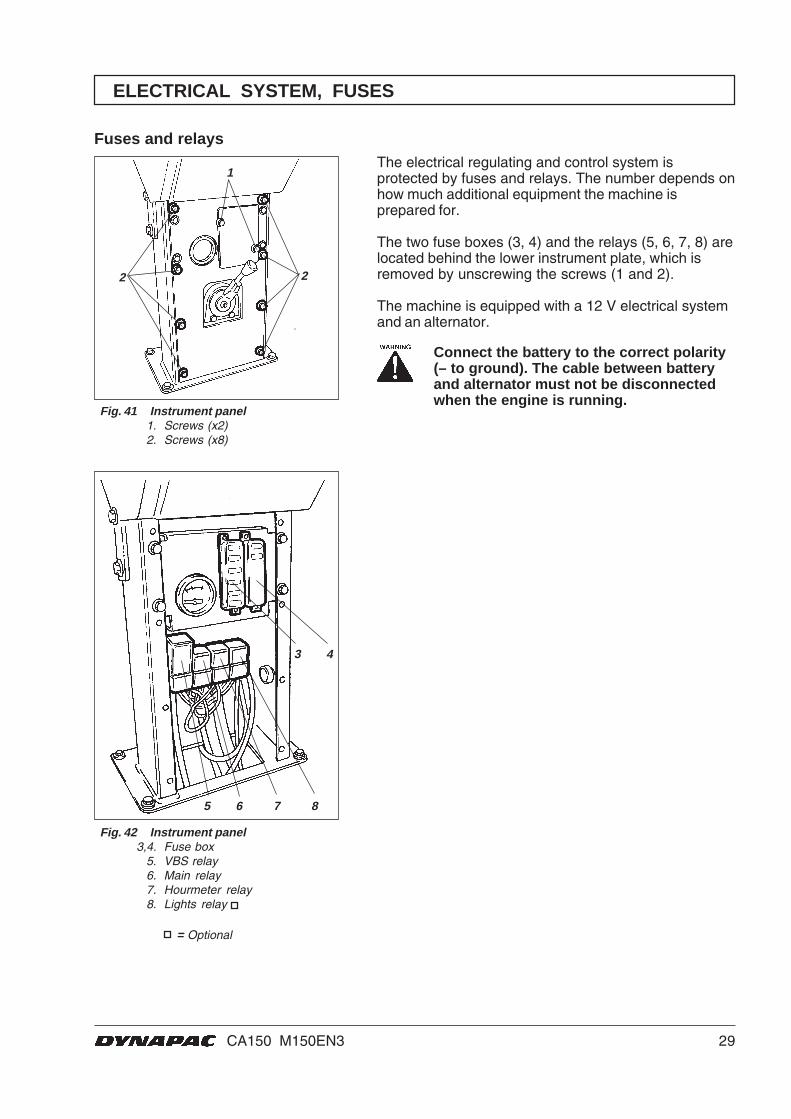
Fig. 42 Instrument panel3,4. Fuse box
5. VBS relay6. Main relay7. Hourmeter relay8. Lights relay
Fig. 41 Instrument panel1. Screws (x2)2. Screws (x8)
Fuses and relays
= Optional
The electrical regulating and control system isprotected by fuses and relays. The number depends onhow much additional equipment the machine isprepared for.
The two fuse boxes (3, 4) and the relays (5, 6, 7, 8) arelocated behind the lower instrument plate, which isremoved by unscrewing the screws (1 and 2).
The machine is equipped with a 12 V electrical systemand an alternator.
Connect the battery to the correct polarity(– to ground). The cable between batteryand alternator must not be disconnectedwhen the engine is running.
30 CA150 M150EN3
Main fuses/Relays
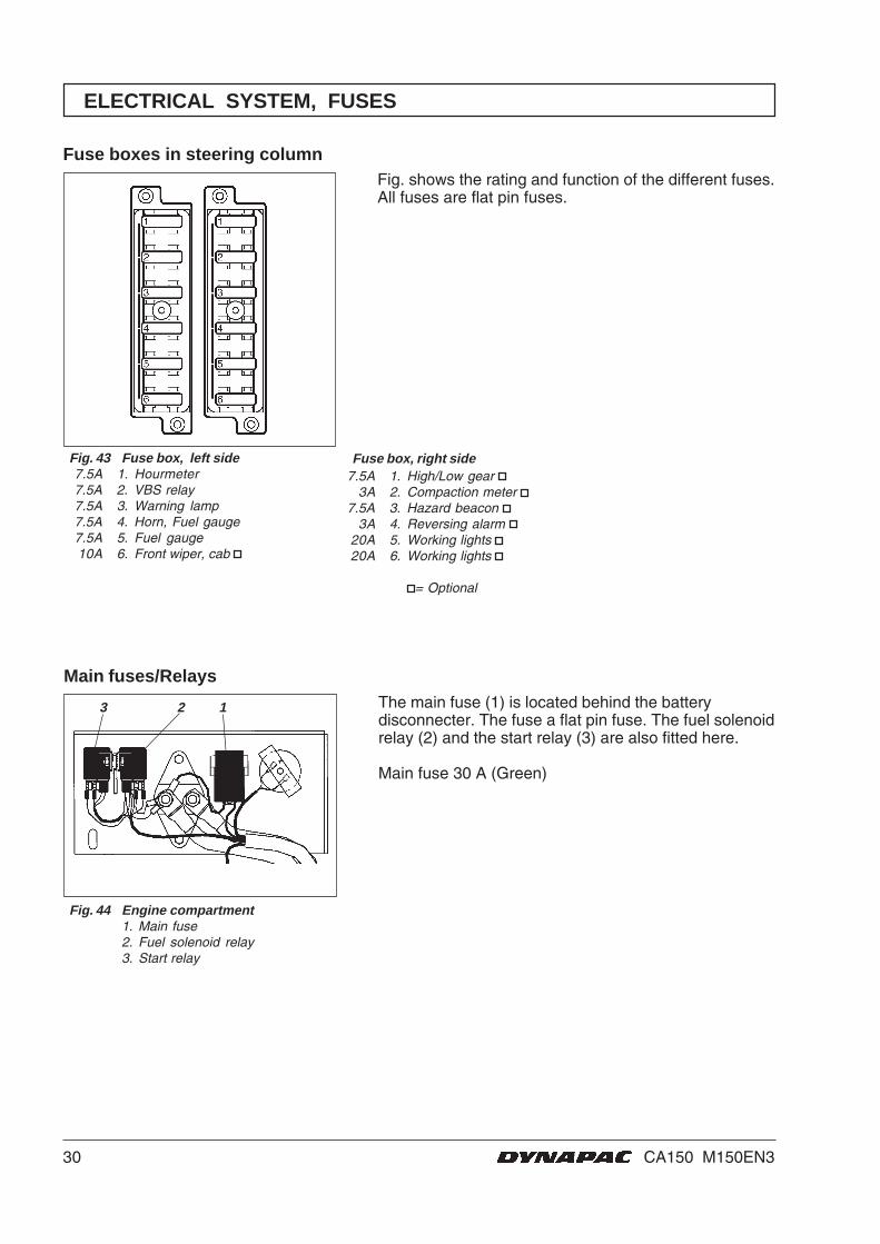
Fig. 44 Engine compartment1. Main fuse2. Fuel solenoid relay3. Start relay
The main fuse (1) is located behind the batterydisconnecter. The fuse a flat pin fuse. The fuel solenoidrelay (2) and the start relay (3) are also fitted here.
Main fuse 30 A (Green)
3 2 1
ELECTRICAL SYSTEM, FUSES
Fuse boxes in steering column
Fig. 43 Fuse box, left side7.5A 1. Hourmeter7.5A 2. VBS relay7.5A 3. Warning lamp7.5A 4. Horn, Fuel gauge7.5A 5. Fuel gauge10A 6. Front wiper, cab
Fig. shows the rating and function of the different fuses.All fuses are flat pin fuses.
Fuse box, right side7.5A 1. High/Low gear
3A 2. Compaction meter 7.5A 3. Hazard beacon
3A 4. Reversing alarm 20A 5. Working lights 20A 6. Working lights
= Optional

19ILF015WO1


