35
TECHNICAL OVERVIEW E1968A GSM/GPRS/EGPRS Test Application For the E5515C/E wireless communications test set and the E1987A fast switching test application
T E C H N I C A L O V E R V I E W
E1968A GSM/GPRS/EGPRSTest ApplicationFor the E5515C/E wireless communications test set and the E1987A fast switching test application

Page 02Find us at www.keysight.com
Accelerate production of high volume quality phones at the lowest possible cost
Flexible – The E1968A includes all essential connection types and signaling options necessary for a
complete GSM/GPRS/ EGPRS/E-EDGE manufacturing test solution – Some licensed feature options can also be used in R&D and reduce your R&D cycle
Fast – Digital ORFS – up to 20x faster – Dynamic power – fast automatic signaling and non-signaling method for Tx output
power calibration – Phase and amplitude versus time (PAvT) – measurement for calibration of polar
modulated devices – Fast device tune (FDT) – faster simultaneous mobile phone Rx and Tx calibration (based on
typical test plan) – Discontinuous timeslot TXP – supports simultaneous power measurement for up to 7
timeslots, reduces phone calibration time
Key features
– PAvT and IQ capture functionality – Enhanced fast device calibration across level and frequency simultaneously – E-EDGE2-A signaling and measurement – VAMOS type I and type II solutions for mobile R&D and manufacturing – Test mode BER reduces your BER measurement time in production without setting up a
call connection; MS calculated BER separates the Rx from Tx test and reduces Rx test time through multi-phone test scenario
– Class 45 feature enables simultaneous Tx and Rx measurement of all bursts up to 6 uplink timeslots
– Real-time audio codec and DAI interface – Free text-type SMS functionality and licensed full functionality SMS – Single channel GPS source – FM radio source allows easy FM radio phone calibration in production – 2-box voice handover between GSM and W-CDMA
GSM/GPRS/EGPRS/E-EDGE Signaling and Base Station EmulationThe E1968A GSM/GPRS/EGPRS/E-EDGE mobile test application gives you the test solution designed especially for your GSM/GPRS/EGPRS test requirements of transceivers and wireless terminals by delivering speed and flexibility needed for high-volume, automated production-test environments. Since this solution is based on the high-performance E5515C/E (8960) wireless communications test set, you get speed and concurrent measurement capabilities, providing immediate benefits that translate into a competitive advantage for mobile phone manufacturers. This significantly cuts test times, helping reduce the manufacturing cost per phone.

Page 03Find us at www.keysight.com
Audio functionality
– Choice of speech encoded on downlink TCH: none, echo, 300 Hz sine, 1 kHz sine, 3 kHz sine, or PRBS-9, PRBS-15, multi-tone, or custom
– GSM analog audio measurement (audio level, distortion, frequency, SINAD) – Uplink and downlink audio measurement with real-time audio codec and DAI – PESQ measurement
Receiver measurements
– GSM fast BER via loopback type C – GSM BER via loopback type A and B – GPRS/EGPRS multislot BER – GPRS/EGPRS multislot block error ratio (BLER) – MS calculated BER – Test mode BER – EGPRS2-A 16QAM/32QAM BEP report
Transmitter measurements
– GPRS/EGPRS multislot transmit power – EGPRS multislot-tolerant transmit power – 8PSK multislot-tolerant modulation accuracy (peak, rms, 95th percentile and sample
EVM; frequency, magnitude and phase errors; origin offset suppression; IQ imbalance) – GMSK multislot-tolerant frequency error – GMSK multislot-tolerant phase error (peak and rms with confidence limits) – Multislot power versus time (burst mask comparison with settable masks) – Burst timing error with signaling – Burst timing error under test mode – Multislot-tolerant output RF spectrum due to modulation and switching – ORFS measurement in time domain – IQ tuning – GSM decoded audio level – Dynamic power – Phase and amplitude versus time (PAvT) – IQ capture – Fast device tune (FDT) – AM-PM timing offset – Discontinuous timeslot TXP measurement – 8PSK/16QAM measurement
Instruments
– Audio generator – General-purpose spectrum monitor – GSM multi-tone audio
Figure 1. Use graphical measurement results to troubleshoot your EGPRS wireless device.
Page 04Find us at www.keysight.com
Integrated GSM, GPRS, and EGPRS Functionality
– Switch between GSM, GPRS, and EGPRS serving cells – Switch between data and voice connections without losing camp or attach – Establish a voice or data connection after initial GPRS attach – Supports Evolved EDGE functionality – Supports EGPRS2-A signaling and test mode measurement
GSM functionality
Mobile station power output level control
Meets GSM phase one and phase two power control levels
Traffic channels TCH/FS – FR, EFR, and HR speech modesBroadcast channel configuration BCCH + CCCH + SDCCH/4Signaling protocol setup FACCH audio speech echo delay is settable from 1 to 4 secondsReal-time audio codec Audio encoder and decoder support FR, HR, EFR, AMR, and
WB-AMR codec
GPRS functionality
Multislot classes supported 1 through 1230 through 45
Control channels BCH on timeslot 0 on any ARFCN in any bandBroadcast channel configuration FCCH + SCH + BCCH + CCCH + SDCCH/4 (0-3) + SACCH/C4 (0-3)Downlink PDTCH One, two, three, or four on the same PDTCH ARFCN with one or two
PDTCH amplitudes settable between 0 and 55 dB below BCH amplitude; amplitudes in adjacent timeslots selectable as off, PRL (power reduction level) one, or PRL two
EGPRS functionality
Multislot classes supported 1 through 1230 through 45
Control channels BCH on timeslot 0 on any ARFCN in any bandBroadcast channel configuration FCCH + SCH + BCCH + CCCH + SDCCH/4 (0-3) + SACCH/C4 (0-3)Downlink PDTCH One, two, three, four, or five on the same PDTCH ARFCN with one or two
PDTCH amplitudes settable between 0 and 55 dB below BCH amplitude; amplitudes in adjacent timeslots selectable as off, PRL one, or PRL two
Evolved EDGE Functionality
Downlink PDTCH – Downlink dual carrier (DLDC) setup – Supports RTTI mode – Fast Ack/Non-Ack setup – 16QAM/32QAM downlink setup – 16QAM uplink setup
Page 05Find us at www.keysight.com
Call Processing Functionality
– GSM MS and BS origination – GSM MS and BS release – GPRS mobile-initiated attach and detach – GPRS and EGPRS packet data transfers on uplink and downlink – E-EDGE and EGPRS2-A call setup – Intra-cell channel assignments – Inter-cell handovers between all bands – Handover from W-CDMA to GSM (with E1987A test application) – 2-box handover from W-CDMA to GSM or GSM to GSM – BA table with 16 settable neighbor cells – External triggers provide a signal output each frame with settable timeslot, bit, and option
to include or exclude the idle frame
BCH setup and parameters – Settable downlink power, band, and channel number – Settable maximum control channel power used by the MS for access bursts of 0 to 31 – Settable maximum control channel power offset value for DCS 1800 MHz band of 0 to 3 – Band indication of DCS or PCS
GSM TCH parameters – Settable downlink in TCH power including power in unused bursts, uplink band, channel
number, and power level – Channel modes of FR, EFR, and HR, plus HR subchannel of 0 or 1 – Settable uplink timeslot of 1 to 7 – Settable timing advance of 0 to 63 – Mobile loopback of off, type A, type B, or type C as defined in ETSI 04.14 or 3GPP 44.014 – Downlink TCH speech types of none, echo, 300 Hz sine, 1 kHz sine, 3 kHz sine, or PRBS-9,
PRBS-15, multi-tone, custom or real-time vocoder
GPRS and EGPRS PDTCH parameters – Settable downlink PDTCH power including power in unused bursts, uplink band, channel
number, and power level – GPRS coding schemes of CS-1, CS-2, CS-3, or CS-4 – EGPRS uplink modulation coding schemes of MCS-1, MCS-2, MCS-3, MCS-4, MCS-5,
MCS-6, MCS-7, MCS-8, or MCS-9 – EGPRS downlink modulation coding schemes: Same as uplink, MCS-1, MCS-2, MCS-3,
MCS-4, MCS-5, MCS-6, MCS-7, MCS-8, or MCS-9 – EGPRS2-A downlink modulation coding schemes: MCS1 to MCS9, DAS5 to DAS12 – EGPRS2-A uplink modulation coding schemes: MCS1 to MCS6, UAS7 to UAS11 – EGPRS modulation coding scheme of 8PSK clear coded in EGPRS BCH+PDTCH
operating mode – (E)GPRS multislot configurations of 1x1, 1x2, 1x3, 1x4, 1x5, 1x6, 2x1, 2x2, 2x3, 2x4, 3x1, 3x2,
3x3, 4x1, 4x2, 5x1, 6x1 (downlink x uplink) – Selection of which contiguous down- link bursts to loop back on the uplink with connection
type ETSI type B or SRB loopback – Selection of which uplink burst to use for multislot-tolerant RF measurements
Page 06Find us at www.keysight.com
Cell parameters – Three-digit MNC off or on in PCS 1900 MHz and GSM 850 MHz bands – Settable MCC, MND, LAC, RAC, NCC, and BCC – Option to get IMEI at call setup – Mobile DTX on or off – Paging mode reorganized or normal – Settable paging multiframes of 2 to 9 – Repeat paging on or off – Tx level FACCH signaling on or off – Symmetric or asymmetric uplink frame segmentation – Settable random frequency offset for BCH and PDTCH
Handover setup – GSM traffic band, traffic channel, timeslot, channel mode, half-rate speech subchannel,
MS Tx level – GPRS traffic band, traffic channel, coding scheme, multislot configuration, P0, MS Tx level
burst 1 to 6 – EGPRS traffic band, traffic channel, downlink modulation coding scheme, uplink
modulation coding scheme, multislot configuration, P0, MS Tx level burst 1 to 6
Protocol control – RLC/MAC header off or on in GPRS BCH+PDTCH operating mode – RLC/MAC header selectable as uplink or downlink in EGPRS BCH+PDTCH operating mode – RLC/MAC packet timeslot reconfigure off or on – RLC/MAC packet power timing advance on or off – Settable RLC/MAC block poll rate of 1 to 256 – RLC/MAC frame start position of relative, absolute, or immediate – LLC BLER FCS of valid or corrupt – Settable LLC payload patterns for connection types ETSI type B or for BLER with corrupt
FCS of all zeros, all ones, alternate bits, alternate pairs, alternate quads, PRBS-9, PRBS-15, fixed 2B (hex), custom, GMM information for BLER
Receiver control – Expected power control auto or manual – Manual power bursts 1 to 6 settable in dBm – Measurement frequency auto or settable in MHz – Modulation formal control auto or manual – Manual modulation of bursts 1 to 6 selectable as GMSK or 8PSK
DUT information – International mobile subscriber identity (IMSI) – International mobile equipment identity (IMEI) (if selected) – GPRS multislot class – EGPRS multislot class – GMSK power class – 8PSK power class
Page 07Find us at www.keysight.com
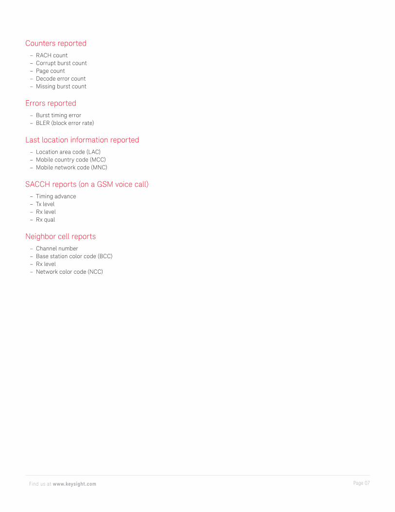
Counters reported – RACH count – Corrupt burst count – Page count – Decode error count – Missing burst count
Errors reported – Burst timing error – BLER (block error rate)
Last location information reported – Location area code (LAC) – Mobile country code (MCC) – Mobile network code (MNC)
SACCH reports (on a GSM voice call) – Timing advance – Tx level – Rx level – Rx qual
Neighbor cell reports – Channel number – Base station color code (BCC) – Rx level – Network color code (NCC)
Page 08Find us at www.keysight.com
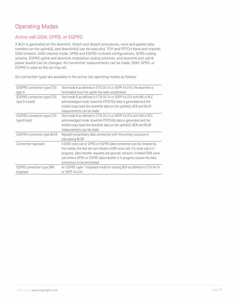
Operating Modes
Active cell GSM, GPRS, or EGPRSA BCH is generated on the downlink. Attach and detach procedures, voice and packet data transfers on the uplink(s), and downlink(s) can be executed. TCH and PDTCH band and channel, GSM timeslot, GSM channel mode, GPRS and EGPRS multislot configurations, GPRS coding scheme, EGPRS uplink and downlink modulation coding schemes, and downlink and uplink power level(s) can be changed. All transmitter measurements can be made. GSM, GPRS, or EGPRS is used as the serving cell.
Six connection types are available in the active cell operating modes as follows:
(E)GPRS connection type ETSI type A
Test mode A as defined in ETSI 04.14 or 3GPP 44.014; the downlink is terminated once the uplink has been established
(E)GPRS connection type ETSI type B (unack)
Test mode B as defined in ETSI 04.14 or 3GPP 44.014 with MS in RLC acknowledged mode; downlink PDTCH(s) data is generated and the mobile loops back the downlink data on the uplink(s); BER and BLER measurements can be made
(E)GPRS connection type ETSI type B (ack)
Test mode B as defined in ETSI 04.14 or 3GPP 44.014 with MS in RCL acknowledged mode; downlink PDTCH(s) data is generated and the mobile loops back the downlink data on the uplink(s); BER and BLER measurements can be made
(E)GPRS connection type BLER Keysight-proprietary data connection with the primary purpose of calculating BLER
Connection type auto A GSM voice call or GPRS or EGPRS data connection can be initiated by the mobile; the test set can initiate a GSM voice call; if a voice call is in progress, data transfer requests are ignored; network-initiated GSM voice call while a GPRS or EGPRS data transfer is in progress causes the data connection to be terminated
EGPRS connection type SRB loopback
An EGPRS Layer 1 loopback mode for testing BER as defined in ETSI 04.14 or 3GPP 44.014
Page 09Find us at www.keysight.com
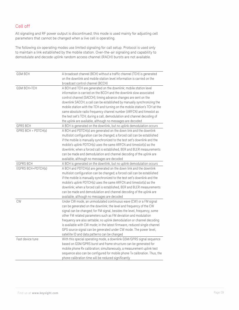
GSM BCH A broadcast channel (BCH) without a traffic channel (TCH) is generated on the downlink and mobile station level information is carried on the broadcast control channel (BCCH)
GSM BCH+TCH A BCH and TCH are generated on the downlink; mobile station level information is carried on the BCCH and the downlink slow associated control channel (SACCH); timing advance changes are sent on the downlink SACCH; a call can be established by manually synchronizing the mobile station with the TCH and turning on the mobile station’s TCH at the same absolute radio frequency channel number (ARFCN) and timeslot as the test set’s TCH; during a call, demodulation and channel decoding of the uplink are available, although no messages are decoded
GPRS BCH A BCH is generated on the downlink, but no uplink demodulation occursGPRS BCH + PDTCH(s) A BCH and PDTCH(s) are generated on the down link and the downlink
multislot configuration can be changed; a forced call can be established if the mobile is manually synchronized to the test set’s downlink and the mobile’s uplink PDTCH(s) uses the same ARFCN and timeslot(s) as the downlink; when a forced call is established, BER and BLER measurements can be made and demodulation and channel decoding of the uplink are available, although no messages are decoded
EGPRS BCH A BCH is generated on the downlink, but no uplink demodulation occursEGPRS BCH+PDTCH(s) A BCH and PDTCH(s) are generated on the down link and the downlink
multislot configuration can be changed; a forced call can be established if the mobile is manually synchronized to the test set’s downlink and the mobile’s uplink PDTCH(s) uses the same ARFCN and timeslot(s) as the downlink; when a forced call is established, BER and BLER measurements can be made and demodulation and channel decoding of the uplink are available, although no messages are decoded
CW Under CW mode, an unmodulated continuous wave (CW) or a FM signal can be generated on the downlink; the level and frequency of the CW signal can be changed; for FM signal, besides the level, frequency, some other FM related parameters such as FM deviation and modulation frequency are also settable; no uplink demodulation or channel decoding is available with CW mode; in the latest firmware, reduced single channel GPS source signal can be generated under CW mode. The power level, satellite ID and data patterns can be changed
Fast device tune With this special operating mode, a downlink GSM/GPRS signal sequence based on GSM/GPRS burst and frame structure can be generated for mobile phone Rx calibration; simultaneously, a measurement uplink test sequence also can be configured for mobile phone Tx calibration. Thus, the phone calibration time will be reduced significantly
Cell offAll signaling and RF power output is discontinued; this mode is used mainly for adjusting cell parameters that cannot be changed when a live cell is operating.
The following six operating modes use limited signaling for call setup. Protocol is used only to maintain a link established by the mobile station. Over-the-air signaling and capability to demodulate and decode uplink random access channel (RACH) bursts are not available.

Page 10Find us at www.keysight.com
Technical Specifications
These specifications apply to an E5515C mainframe with Option 002, or E5515E when used with the E1968A test application of firmware revision A.09 or higher, or the E1987A test application of firmware revision A.08 or higher. Depending on the exact configuration, earlier E5515C and E5515B instruments may require hardware upgrades to obtain certain features and capability. Features which may require hardware upgrades include: EGPRS (all capability), higher EGPRS multislot classes, spectrum monitor, RF out only port, phase and amplitude versus time (PAvT), fast device tune, and ORFS digital filter option.
CAUTION: Loading an application onto your E5515C/E test set that is not compatible with your E5515C/E’s hardware revision can cause your E5515C/E to lock-up. For information on application/E5515C/E compatibility go to www.keysight.com/find/E5515C and select the relevant link to E5515C/E Release Notes. Always refer to this information before loading an application.
Supplemental characteristics are intended to provide additional information useful in applying the instrument by giving typical, but non-warranted performance parameters. These characteristics are shown in italics and labeled as “typical,” or “supplemental,” and apply at +25 °C.
RF generator level accuracy is derived from 95th percentile observations with 95 percent confidence (corresponds to an expanded uncertainty with a 95 percent confidence (k=2)) at ambient conditions, then qualified to include the environmental effects of temperature and humidity.
RF (downlink) generator specificationsRF generator specifications apply to both RF IN/OUT and the RF OUT ONLY port on the 8960 (E5515C/E).
RF frequencyFrequency ranges 450 to 496 MHz, 700 to 800 MHz, 810 to 960 MHz, 1.7 to 1.9 GHzAccuracy and stability Same as timebase referenceSupplemental characteristicsTypical CW frequency switching speed
< 10 ms to be within < 0.1 ppm of final frequency
Operating frequency range 292 to 2700 MHzSetting resolution 1 HzRF amplitudeOutput level range at RF IN/OUT
−110 to –13 dBm
Output level range at RF OUT ONLY
−110 to –5 dBm
Absolute output level accuracy < ± 1.0 dBVSWR at RF IN/OUT < 1.14 : 1 for 450 to 496 MHz and 810 to 960 MHz, < 1.2 : 1 for 1.7
to 1.99 GHzReverse power at RF IN/OUT < 2.5 W continuous, < 5 W peak bursted powerReverse power at RF OUT ONLY < 500 mW continuous
Page 11Find us at www.keysight.com
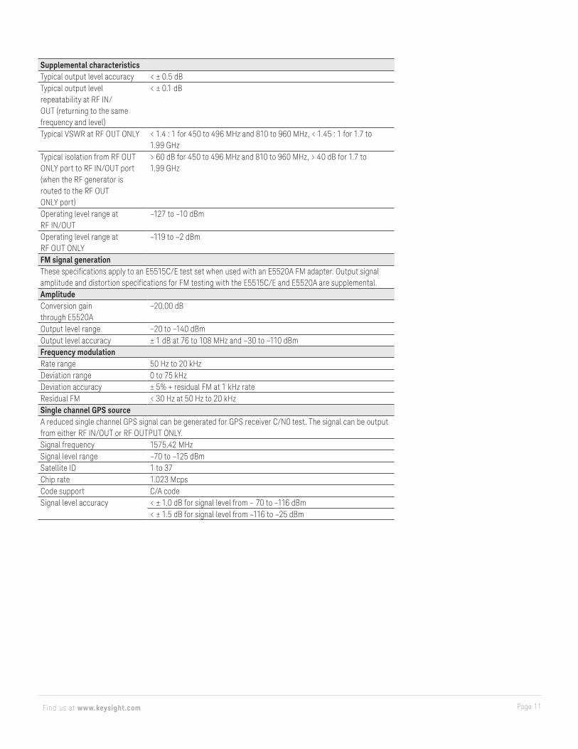
Supplemental characteristicsTypical output level accuracy < ± 0.5 dBTypical output level repeatability at RF IN/OUT (returning to the same frequency and level)
< ± 0.1 dB
Typical VSWR at RF OUT ONLY < 1.4 : 1 for 450 to 496 MHz and 810 to 960 MHz, < 1.45 : 1 for 1.7 to 1.99 GHz
Typical isolation from RF OUT ONLY port to RF IN/OUT port (when the RF generator is routed to the RF OUT ONLY port)
> 60 dB for 450 to 496 MHz and 810 to 960 MHz, > 40 dB for 1.7 to 1.99 GHz
Operating level range at RF IN/OUT
–127 to –10 dBm
Operating level range at RF OUT ONLY
–119 to –2 dBm
FM signal generationThese specifications apply to an E5515C/E test set when used with an E5520A FM adapter. Output signal amplitude and distortion specifications for FM testing with the E5515C/E and E5520A are supplemental.AmplitudeConversion gain through E5520A
−20.00 dB
Output level range −20 to −140 dBmOutput level accuracy ± 1 dB at 76 to 108 MHz and −30 to −110 dBmFrequency modulationRate range 50 Hz to 20 kHzDeviation range 0 to 75 kHzDeviation accuracy ± 5% + residual FM at 1 kHz rateResidual FM < 30 Hz at 50 Hz to 20 kHzSingle channel GPS sourceA reduced single channel GPS signal can be generated for GPS receiver C/N0 test. The signal can be output from either RF IN/OUT or RF OUTPUT ONLY.Signal frequency 1575.42 MHzSignal level range –70 to –125 dBmSatellite ID 1 to 37Chip rate 1.023 McpsCode support C/A codeSignal level accuracy < ± 1.0 dB for signal level from – 70 to –116 dBm
< ± 1.5 dB for signal level from –116 to –25 dBm
Page 12Find us at www.keysight.com
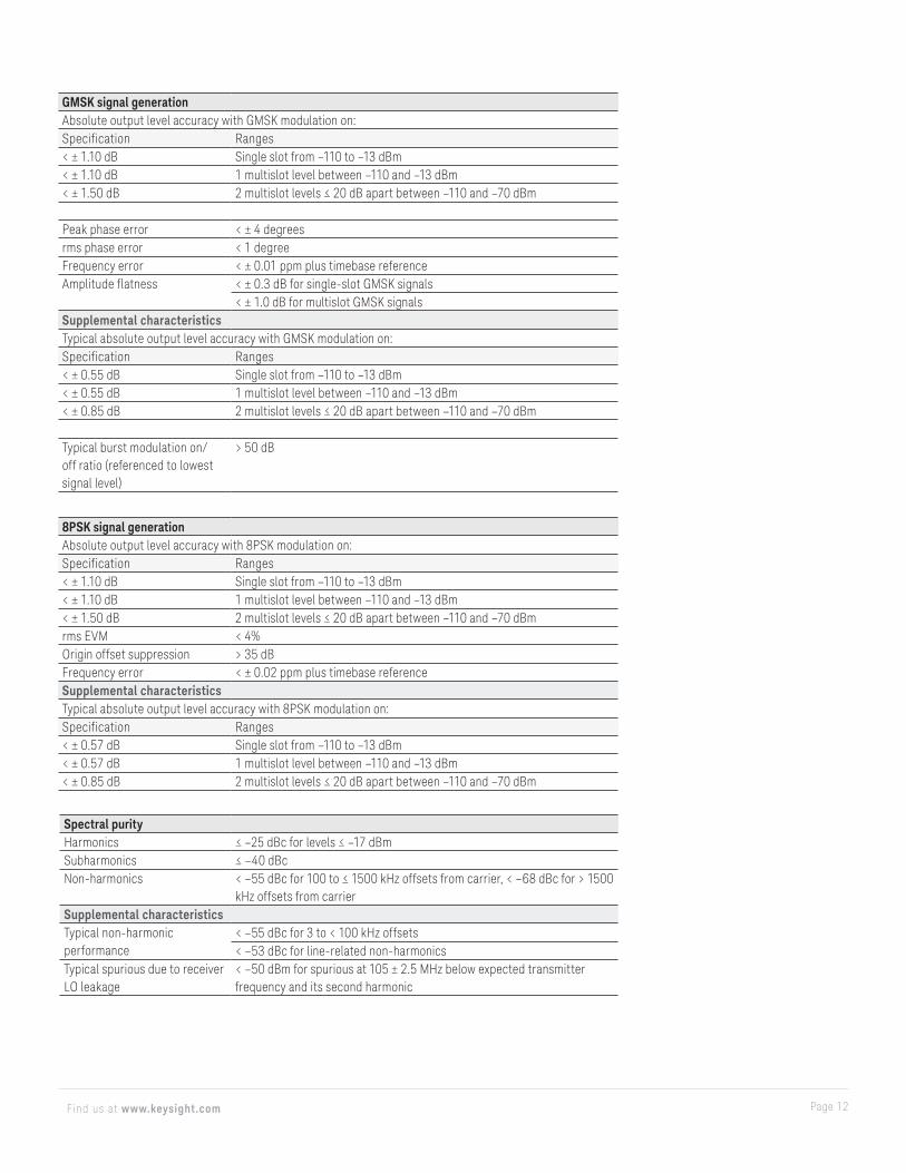
GMSK signal generationAbsolute output level accuracy with GMSK modulation on:Specification Ranges< ± 1.10 dB Single slot from –110 to –13 dBm< ± 1.10 dB 1 multislot level between –110 and –13 dBm< ± 1.50 dB 2 multislot levels ≤ 20 dB apart between –110 and –70 dBm
Peak phase error < ± 4 degreesrms phase error < 1 degreeFrequency error < ± 0.01 ppm plus timebase referenceAmplitude flatness < ± 0.3 dB for single-slot GMSK signals
< ± 1.0 dB for multislot GMSK signalsSupplemental characteristicsTypical absolute output level accuracy with GMSK modulation on:Specification Ranges< ± 0.55 dB Single slot from –110 to –13 dBm< ± 0.55 dB 1 multislot level between –110 and –13 dBm< ± 0.85 dB 2 multislot levels ≤ 20 dB apart between –110 and –70 dBm
Typical burst modulation on/off ratio (referenced to lowest signal level)
> 50 dB
8PSK signal generationAbsolute output level accuracy with 8PSK modulation on:Specification Ranges< ± 1.10 dB Single slot from –110 to –13 dBm< ± 1.10 dB 1 multislot level between –110 and –13 dBm< ± 1.50 dB 2 multislot levels ≤ 20 dB apart between –110 and –70 dBmrms EVM < 4%Origin offset suppression > 35 dBFrequency error < ± 0.02 ppm plus timebase referenceSupplemental characteristicsTypical absolute output level accuracy with 8PSK modulation on:Specification Ranges< ± 0.57 dB Single slot from –110 to –13 dBm< ± 0.57 dB 1 multislot level between –110 and –13 dBm< ± 0.85 dB 2 multislot levels ≤ 20 dB apart between –110 and –70 dBm
Spectral purityHarmonics ≤ –25 dBc for levels ≤ –17 dBmSubharmonics ≤ –40 dBcNon-harmonics < –55 dBc for 100 to ≤ 1500 kHz offsets from carrier, < –68 dBc for > 1500
kHz offsets from carrierSupplemental characteristicsTypical non-harmonic performance
< –55 dBc for 3 to < 100 kHz offsets< –53 dBc for line-related non-harmonics
Typical spurious due to receiver LO leakage
< –50 dBm for spurious at 105 ± 2.5 MHz below expected transmitter frequency and its second harmonic
Page 13Find us at www.keysight.com
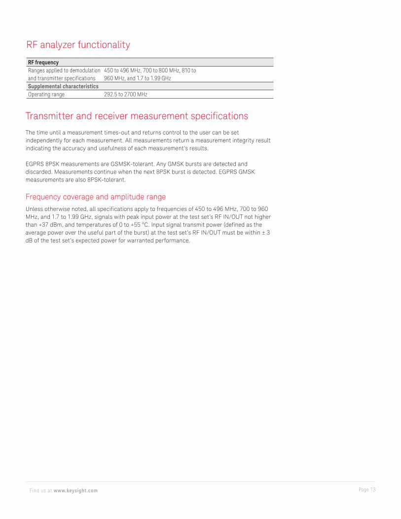
RF analyzer functionality
RF frequencyRanges applied to demodulation and transmitter specifications
450 to 496 MHz, 700 to 800 MHz, 810 to 960 MHz, and 1.7 to 1.99 GHz
Supplemental characteristicsOperating range 292.5 to 2700 MHz
Transmitter and receiver measurement specifications
The time until a measurement times-out and returns control to the user can be set independently for each measurement. All measurements return a measurement integrity result indicating the accuracy and usefulness of each measurement’s results.
EGPRS 8PSK measurements are GSMSK-tolerant. Any GMSK bursts are detected and discarded. Measurements continue when the next 8PSK burst is detected. EGPRS GMSK measurements are also 8PSK-tolerant.
Frequency coverage and amplitude rangeUnless otherwise noted, all specifications apply to frequencies of 450 to 496 MHz, 700 to 960 MHz, and 1.7 to 1.99 GHz, signals with peak input power at the test set’s RF IN/OUT not higher than +37 dBm, and temperatures of 0 to +55 °C. Input signal transmit power (defined as the average power over the useful part of the burst) at the test set’s RF IN/OUT must be within ± 3 dB of the test set’s expected power for warranted performance.
Page 14Find us at www.keysight.com
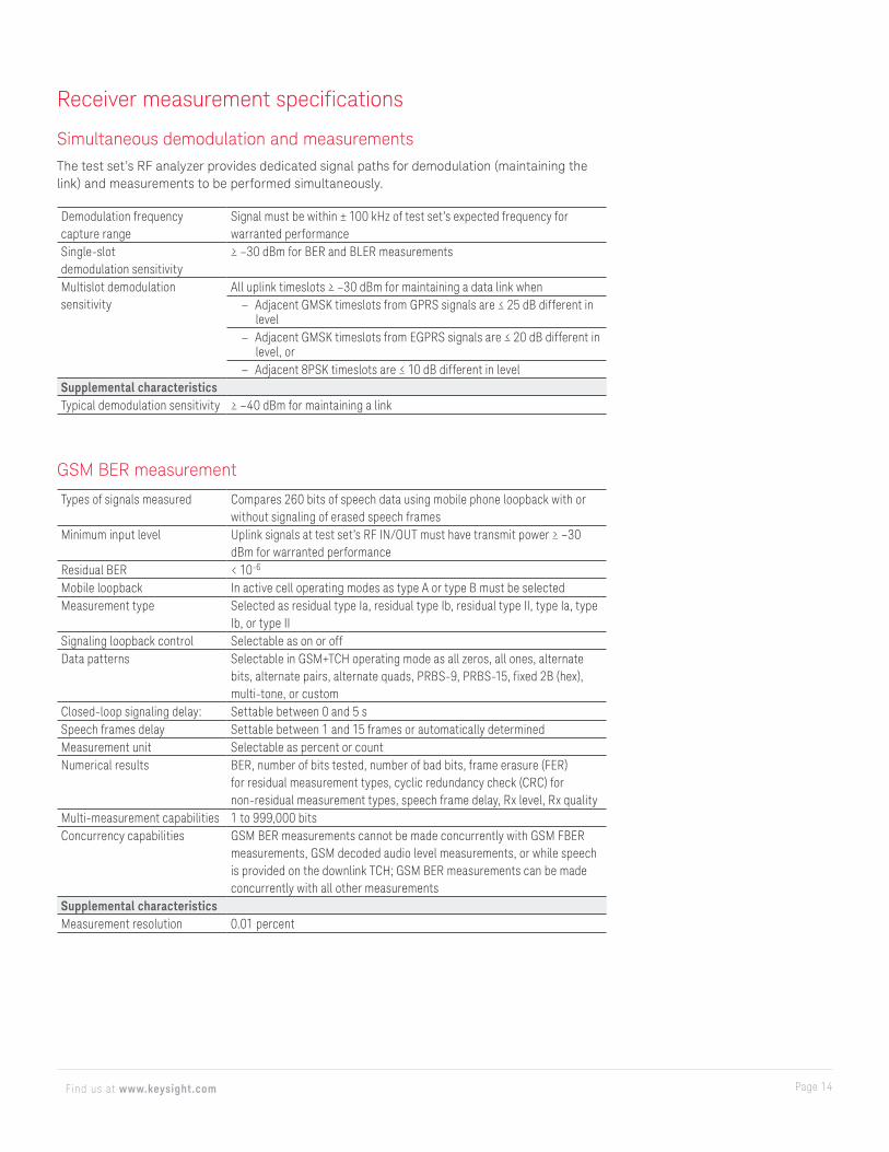
Receiver measurement specifications
Simultaneous demodulation and measurementsThe test set’s RF analyzer provides dedicated signal paths for demodulation (maintaining the link) and measurements to be performed simultaneously.
Demodulation frequency capture range
Signal must be within ± 100 kHz of test set’s expected frequency for warranted performance
Single-slot demodulation sensitivity
≥ –30 dBm for BER and BLER measurements
Multislot demodulation sensitivity
All uplink timeslots ≥ –30 dBm for maintaining a data link when – Adjacent GMSK timeslots from GPRS signals are ≤ 25 dB different in
level – Adjacent GMSK timeslots from EGPRS signals are ≤ 20 dB different in
level, or – Adjacent 8PSK timeslots are ≤ 10 dB different in level
Supplemental characteristicsTypical demodulation sensitivity ≥ –40 dBm for maintaining a link
GSM BER measurement
Types of signals measured Compares 260 bits of speech data using mobile phone loopback with or without signaling of erased speech frames
Minimum input level Uplink signals at test set’s RF IN/OUT must have transmit power ≥ –30 dBm for warranted performance
Residual BER < 10-6
Mobile loopback In active cell operating modes as type A or type B must be selectedMeasurement type Selected as residual type Ia, residual type Ib, residual type II, type Ia, type
Ib, or type IISignaling loopback control Selectable as on or offData patterns Selectable in GSM+TCH operating mode as all zeros, all ones, alternate
bits, alternate pairs, alternate quads, PRBS-9, PRBS-15, fixed 2B (hex), multi-tone, or custom
Closed-loop signaling delay: Settable between 0 and 5 sSpeech frames delay Settable between 1 and 15 frames or automatically determinedMeasurement unit Selectable as percent or countNumerical results BER, number of bits tested, number of bad bits, frame erasure (FER)
for residual measurement types, cyclic redundancy check (CRC) for non-residual measurement types, speech frame delay, Rx level, Rx quality
Multi-measurement capabilities 1 to 999,000 bitsConcurrency capabilities GSM BER measurements cannot be made concurrently with GSM FBER
measurements, GSM decoded audio level measurements, or while speech is provided on the downlink TCH; GSM BER measurements can be made concurrently with all other measurements
Supplemental characteristicsMeasurement resolution 0.01 percent
Page 15Find us at www.keysight.com
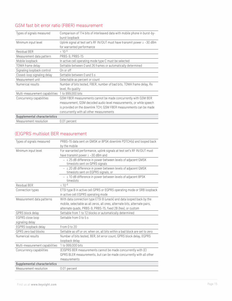
GSM fast bit error ratio (FBER) measurement
Types of signals measured Comparison of 114 bits of interleaved data with mobile phone in burst-by-burst loopback
Minimum input level Uplink signal at test set’s RF IN/OUT must have transmit power ≥ –30 dBm for warranted performance
Residual BER < 10-6
Measurement data pattern PRBS-9, PRBS-15Mobile loopback In active cell operating mode type C must be selectedTDMA frame delay Settable between 0 and 26 frames or automatically determinedSignaling loopback control On or offClosed-loop signaling delay Settable between 0 and 5 sMeasurement unit Selectable as percent or countNumerical results Number of bits tested, FBER, number of bad bits, TDMA frame delay, Rx
level, Rx qualityMulti-measurement capabilities 1 to 999,000 bitsConcurrency capabilities GSM FBER measurements cannot be made concurrently with GSM BER
measurement, GSM decoded audio level measurements, or while speech is provided on the downlink TCH; GSM FBER measurements can be made concurrently with all other measurements
Supplemental characteristicsMeasurement resolution 0.01 percent
(E)GPRS multislot BER measurement
Types of signals measured PRBS-15 data sent on GMSK or 8PSK downlink PDTCH(s) and looped back by the mobile
Minimum input level For warranted performance, uplink signals at test set’s RF IN/OUT must have transmit power ≥ –30 dBm and
– ≤ 25 dB difference in power between levels of adjacent GMSK timeslots sent on GPRS signals
– ≤ 20 dB difference in power between levels of adjacent GMSK timeslots sent on EGPRS signals, or
– ≤ 10 dB difference in power between levels of adjacent 8PSK timeslots
Residual BER < 10-6
Connection types ETSI type B in active cell GPRS or EGPRS operating mode or SRB loopback in active cell EGPRS operating mode
Measurement data patterns With data connection type ETSI B (unack) and data looped back by the mobile, selectable as all zeros, all ones, alternate bits, alternate pairs, alternate quads, PRBS-9, PRBS-15, fixed 2B (hex), or custom
GPRS block delay Settable from 1 to 12 blocks or automatically determinedEGPRS close loop signaling delay
Settable from 0 to 5 s
EGPRS loopback delay From 0 to 20GPRS zero bad blocks Settable as off or on; when on, all bits within a bad block are set to zeroNumerical results Number of bits tested, BER, bit error count, GPRS block delay, EGPRS
loopback delayMulti-measurement capabilities 1 to 999,000 bitsConcurrency capabilities (E)GPRS BER measurements cannot be made concurrently with (E)
GPRS BLER measurements, but can be made concurrently with all other measurements
Supplemental characteristicsMeasurement resolution 0.01 percent

Page 16Find us at www.keysight.com
(E)GPRS multislot BLER measurement
Types of signals measured GMSK data looped back by the mobile using connection type ETSI type B (unack), 8PSK data looped back by the mobile using connection type SRB loopback, or information reported by the mobile in Packet_Uplink_Ack_Nack messages using connection type ETSI type B (ack) or BLER
Minimum input level For warranted performance, uplink signals at test set’s RF IN/OUT must have transmit power ≥ –30 dBm and
For warranted performance, uplink signals at test set’s RF IN/OUT must have transmit power ≥ –30 dBm and
≤ 25 dB difference in power between levels of adjacent GMSK timeslots sent on GPRS signals≤ 20 dB difference in power between levels of adjacent GMSK timeslots sent on EGPRS signals, or≤ 10 dB difference in power between levels of adjacent 8PSK timeslots
Connection types Settable as ETSI type B (unack), ETSI type B (ack), BLER (for GPRS), or SRB loopback (for EGPRS)
Measurement data patterns With data connection type ETSI B (unack) and data looped back by the mobile, selectable as all zeros, all ones, all alternate bits, alternate pairs, alternate quads, PRBS-9, PRBS-15, or fixed 2B (hex), or custom
Block delay Settable between 1 and 6 blocks or automatically determinedNumerical results Number of blocks tested, BLER, block error count, BLER of each burst (for
connection type ETSI type B (ack), or BLER), level of each downlink burst, block delay
Multi-measurement capabilities 1 to 99,000 blocksConcurrency capabilities GPRS/EGPRS BLER measurements cannot be made concurrently with
GPRS/EGPRS BER measurements, but can be made concurrently with all other measurements
Supplemental characteristicsMeasurement resolution 0.01 percent
Page 17Find us at www.keysight.com
Transmitter measurement specifications
Unless otherwise specified, transmitter measurements can be performed in active cell (GSM), active cell (GPRS), and active cell (EGPRS) operating modes.
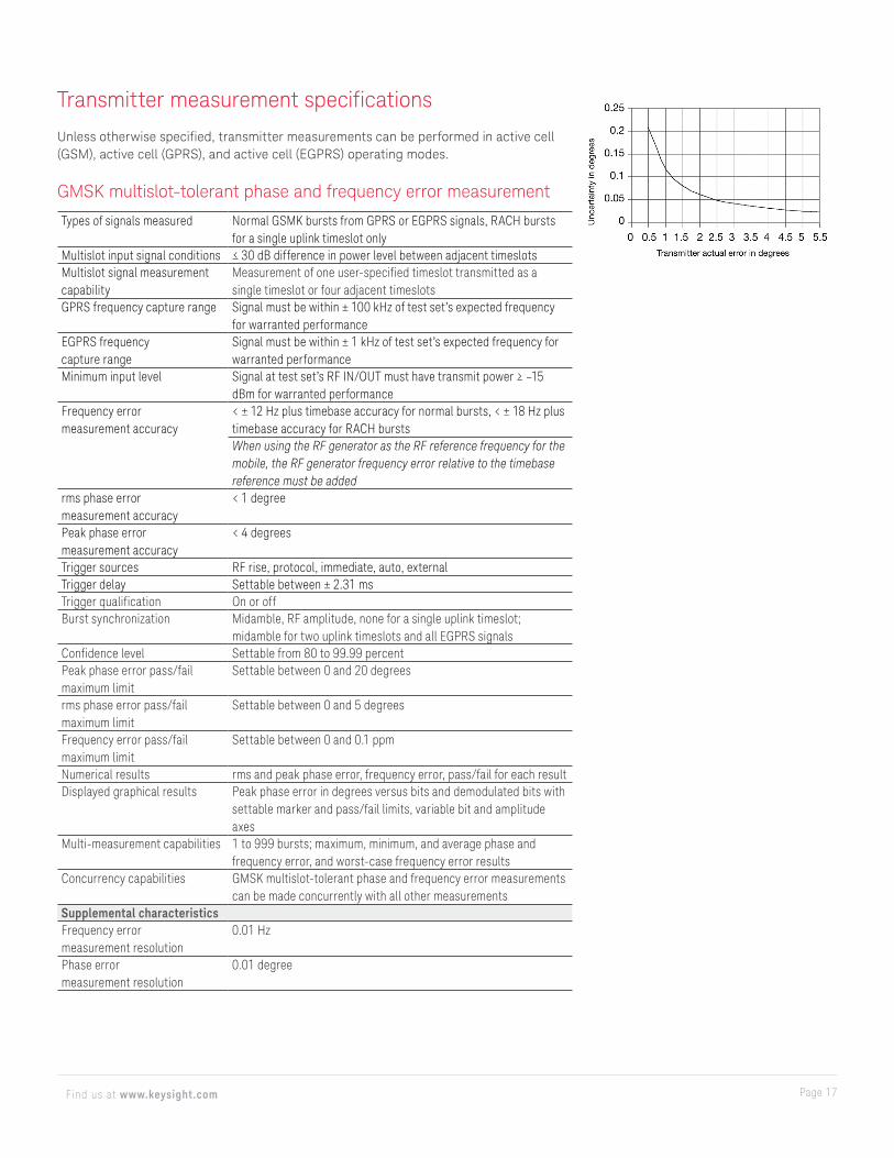
GMSK multislot-tolerant phase and frequency error measurement
Types of signals measured Normal GSMK bursts from GPRS or EGPRS signals, RACH bursts for a single uplink timeslot only
Multislot input signal conditions ≤ 30 dB difference in power level between adjacent timeslotsMultislot signal measurement capability
Measurement of one user-specified timeslot transmitted as a single timeslot or four adjacent timeslots
GPRS frequency capture range Signal must be within ± 100 kHz of test set’s expected frequency for warranted performance
EGPRS frequency capture range
Signal must be within ± 1 kHz of test set’s expected frequency for warranted performance
Minimum input level Signal at test set’s RF IN/OUT must have transmit power ≥ –15 dBm for warranted performance
Frequency error measurement accuracy
< ± 12 Hz plus timebase accuracy for normal bursts, < ± 18 Hz plus timebase accuracy for RACH burstsWhen using the RF generator as the RF reference frequency for the mobile, the RF generator frequency error relative to the timebase reference must be added
rms phase error measurement accuracy
< 1 degree
Peak phase error measurement accuracy
< 4 degrees
Trigger sources RF rise, protocol, immediate, auto, externalTrigger delay Settable between ± 2.31 msTrigger qualification On or offBurst synchronization Midamble, RF amplitude, none for a single uplink timeslot;
midamble for two uplink timeslots and all EGPRS signalsConfidence level Settable from 80 to 99.99 percentPeak phase error pass/fail maximum limit
Settable between 0 and 20 degrees
rms phase error pass/fail maximum limit
Settable between 0 and 5 degrees
Frequency error pass/fail maximum limit
Settable between 0 and 0.1 ppm
Numerical results rms and peak phase error, frequency error, pass/fail for each resultDisplayed graphical results Peak phase error in degrees versus bits and demodulated bits with
settable marker and pass/fail limits, variable bit and amplitude axes
Multi-measurement capabilities 1 to 999 bursts; maximum, minimum, and average phase and frequency error, and worst-case frequency error results
Concurrency capabilities GMSK multislot-tolerant phase and frequency error measurements can be made concurrently with all other measurements
Supplemental characteristicsFrequency error measurement resolution
0.01 Hz
Phase error measurement resolution
0.01 degree

Page 18Find us at www.keysight.com
8PSK/16QAM multislot-tolerant modulation accuracy measurementAll specifications for the 8PSK/16QAM multislot-tolerant modulation accuracy measurement are valid for the frequency ranges 700 to 800 MHz, 810 to 960 MHz, and 1.7 to 1.99 GHz.
Types of signals measured Normal 8PSK/16QAM burstsMultislot input signal conditions ≤ 30 dB difference in power level between adjacent timeslotsMultislot signal measurement capability
Measurement of one user-specified timeslot transmitted as a single timeslot or four adjacent timeslots
Frequency capture range Signal must be within ± 200 Hz of test set’s expected frequency for warranted performance
Minimum input level Signal at test set’s RF IN/OUT must have 8PSK/16QAM burst power ≥ –15 dBm for warranted performance
Residual rms EVM < 1 percent for 8PSK< 1 percent for 8PSK difference ≤ 30 dB
rms EVM measurement accuracy
< 0.5 or > –1.0 for 8PSK< 1.5 or > 2.0 for 16QAM for measured average rms EVM between 1 and 10 percent
Sample EVM measurement accuracy
< ± 4 percent
Frequency error measurement accuracy
< ± 10 Hz plus timebase accuracy
Origin offset suppression measurement accuracy for 8PSK
< ± 1.5 dB for measured origin offset suppression between 25 and 40 dB
Trigger sources RF rise, protocol, immediate, auto, externalTrigger delay Settable between ± 2.31 msBurst synchronization MidambleDisplayed graphical results EVM versus symbol, demodulated symbols in octal and binary, magnitude
error versus symbol, phase error versus symbol, sample EVM histogram with plots of measured sample EVM PDF, expected sample EVM PDF, 95th percentile EVM, and probability with settable markers and variable axes
Multi-measurement capabilities 1 to 999 bursts; maximum, minimum, and average resultsConcurrency capabilities 8PSK multislot-tolerant modulation accuracy measurements can be made
concurrently with all other measurements
Supplemental characteristicsMeasurement resolution 0.01 percentFrequency error measurement resolution
0.01 Hz
Origin offset suppression measurement resolution
0.01 dB
Amplitude droop measurement resolution
0.01 dB
Magnitude error measurement resolution
0.01 percent
Phase error measurement resolution
0.01 degree
IQ imbalance measurement resolution
0.01 dB
Probability measurement resolution
0.01 percent
Page 19Find us at www.keysight.com
GSM/GPRS/EGPRS multislot transmit power measurementThe following specifications are valid when the burst capture range is set to Single:
Types of signals measured Normal GMSK bursts sent as GSM or GPRS signals, CW, RACH bursts for a single uplink timeslot only
Multislot input signal conditions ≤ 30 dB difference in power level between adjacent timeslots
Multislot signal measurement capability
Measurement of one user-specified timeslot transmitted as a single timeslot or two adjacent timeslots
Frequency capture range Signal must be within ± 100 kHz of test set’s expected frequency for warranted performance
Minimum input level Signal at test set’s RF IN/OUT must have transmit power ≥ –25 dBm for warranted performanceMeasurement accuracy at RF IN/OUT port between +20 and +55 °CAccuracy (dBm) Frequency (MHz) Timeslot
< ± 0.27< ± 0.29
810 to 960450 to 496700 to 8001700 to 1990
Single slot and multislot at the same level
< ± 0.52< ± 0.54
810 to 960450 to 496700 to 8001700 to 1990
Multislot at different levels
Measurement accuracy when RF OUT ONLY port is selected for signal generation (in addition to measurement accuracy at RF IN/OUT port):
Accuracy (dBm) Frequency (MHz)< ± 0.27< ± 0.29
450 to 496700 to 800810 to 960
< ± 0.52< ± 0.54
1700 to 1990
VSWR at RF IN/OUT < 1.14 : 1 for 450 to 496 MHz and 700 to 960 MHz, < 1.2 : 1 for 1.7 to 1.99 GHz
Trigger sources RF rise, protocol, immediate, auto, externalTrigger delay Settable between ± 2.31 msBurst synchronization RF amplitude (GSM/GPRS midamble-synchronized transmit
power result is available as part of the multislot power versus time measurement)
Numerical result GMSK transmit powerMulti-measurement capabilities 1 to 999 bursts; minimum, maximum, average, and standard
deviation resultsConcurrency capabilities
GSM/GPRS/EGPRS multislot-tolerant transmit power measurements can be made concurrently with all other measurements
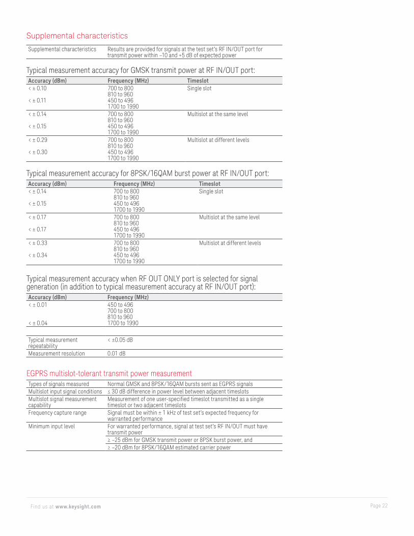
Supplemental characteristicsExtended amplitude range Results are provided for signals at the test set’s RF IN/OUT port for
transmit power within –10 and +5 dB of expected power
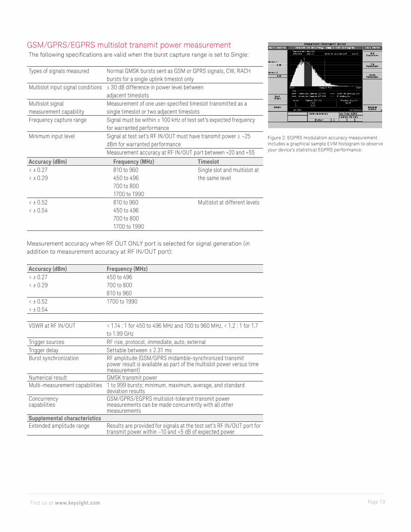
Figure 2. EGPRS modulation accuracy measurement includes a graphical sample EVM histogram to observe your device’s statistical EGPRS performance.
Page 20Find us at www.keysight.com
Typical measurement accuracy at RF IN/OUT port: Accuracy (dBm) Frequency (MHz) Timeslot< ± 0.10< ± 0.13
< ± 0.14
450 to 496700 to 800810 to 9601700 to 1990
Single slot and multislot at the same level
< ± 0.32< ± 0.36
< ± 0.38
450 to 496700 to 800810 to 9601700 to 1990
Multislot at different levels
Typical measurement accuracy when RF OUT ONLY port is selected for signal generation (in addition to typical measurement accuracy at RF IN/OUT port):Accuracy (dBm) Frequency (MHz)< ± 0.01
< ± 0.04
450 to 496700 to 800810 to 9601700 to 1990
Typical measurement repeatability
< ± 0.05 dB
Measurement resolution 0.01 dBThe following specifications are valid when the burst capture range is set to All:Types of signals measured Normal GMSK bursts sent as GSM or GPRS signals, normal GMSK and
8PSK bursts sent as EGPRS signals, CW, RACH bursts for a single uplink timeslot only
Multislot input signal conditions < 30 dB difference in power level between adjacent timeslots. When autoranging is off, input signal transmit power must be within ± 3 dB for highest burst and +3 dB/–30 dB for other bursts relative to expected power of highest burst; when autoranging is on, input signal transmit power must be within ± 3 dB/–30 dB for all bursts
Multislot signal measurement capability
Simultaneous measurement of all bursts up to 6 uplink timeslots in the multislot Class 45 configuration
Frequency capture range Signal must be within ± 100 kHz of the test set’s expected frequency for warranted performance
Minimum input level For warranted performance, signal at test set’s RF IN/OUT must have transmit power > –25 dBm for GMSK transmit power or 8PSK burst power, and > –20 dBm for 8PSK estimated carrier power
Measurement accuracy for GMSK transmit power at RF IN/OUT port between +20 and +55 °CAccuracy (dBm) Frequency (MHz) Timeslot< ± 0.27
< ± 0.29
700 to 800810 to 960450 to 4961700 to 1990
Single slot
< ± 0.32
< ± 0.34
700 to 800810 to 960450 to 4961700 to 1990
Multislot at the same level
< ± 0.70
< ± 0.72
700 to 800810 to 960450 to 4961700 to 1990
Multislot at different levels
Page 21Find us at www.keysight.com
Measurement accuracy for 8PSK burst power at RF IN/OUT port between +20 and +55 °CAccuracy (dBm) Frequency (MHz) Timeslot< ± 0.32
< ± 0.33
700 to 800810 to 960450 to 4961700 to 1990
Single slot
< ± 0.36
< ± 0.37
700 to 800810 to 960450 to 4961700 to 1990
Multislot at the same level
< ± 0.75
< ± 0.76
700 to 800810 to 960450 to 4961700 to 1990
Multislot at different levels
Measurement accuracy for 8PSK/16QAM estimated carrier power at RF IN/OUT port between +20 and +55 °CAccuracy (dBm) Frequency (MHz) Timeslot< ± 0.42
< ± 0.43
700 to 800810 to 960450 to 4961700 to 1990
Single slot
< ± 0.46
< ± 0.47
700 to 800810 to 960450 to 4961700 to 1990
Multislot at the same level
< ± 0.85
< ± 0.86
700 to 800810 to 960450 to 4961700 to 1990
Multislot at different levels
Note: 8PSK estimated carrier power specifications above can be met when signal quality is not degraded.
Measurement accuracy when RF OUT ONLY port is selected for signal generation (in addition to measurement accuracy at RF IN/OUT port)Accuracy (dBm) Frequency (MHz)< ± 0.01
< ± 0.04
450 to 496700 to 800810 to 9601700 to 1990
VSWR at RF IN/OUT < 1.14 : 1 for 450 to 496 MHz and 700 to 960 MHz, < 1.2 : 1 for 1.7 to 1.99 GHz
Trigger sources RF rise, protocol, immediate, auto, externalTrigger delay Settable between ± 2.31 msBurst synchronization MidambleNumerical result GMSK transmit power, 8PSK burst power, 8PSK estimated carrier power,
16QAM burst power, 16QAM estimated carrier powerMulti-measurement capabilities 1 to 999 bursts; minimum, maximum, average, and standard deviation
resultsConcurrency capabilities GSM/GPRS/EGPRS multislot transmit power measurements can be made
concurrently with all other measurements
Page 22Find us at www.keysight.com
Typical measurement accuracy for GMSK transmit power at RF IN/OUT port:Accuracy (dBm) Frequency (MHz) Timeslot< ± 0.10
< ± 0.11
700 to 800810 to 960450 to 4961700 to 1990
Single slot
< ± 0.14
< ± 0.15
700 to 800810 to 960450 to 4961700 to 1990
Multislot at the same level
< ± 0.29
< ± 0.30
700 to 800810 to 960450 to 4961700 to 1990
Multislot at different levels
Typical measurement accuracy for 8PSK/16QAM burst power at RF IN/OUT port:Accuracy (dBm) Frequency (MHz) Timeslot< ± 0.14
< ± 0.15
700 to 800810 to 960450 to 4961700 to 1990
Single slot
< ± 0.17
< ± 0.17
700 to 800810 to 960450 to 4961700 to 1990
Multislot at the same level
< ± 0.33
< ± 0.34
700 to 800810 to 960450 to 4961700 to 1990
Multislot at different levels
Supplemental characteristics
Supplemental characteristics Results are provided for signals at the test set’s RF IN/OUT port for transmit power within –10 and +5 dB of expected power
Typical measurement accuracy when RF OUT ONLY port is selected for signal generation (in addition to typical measurement accuracy at RF IN/OUT port):Accuracy (dBm) Frequency (MHz)< ± 0.01
< ± 0.04
450 to 496700 to 800810 to 9601700 to 1990
Typical measurement repeatability
< ±0.05 dB
Measurement resolution 0.01 dB
EGPRS multislot-tolerant transmit power measurement Types of signals measured Normal GMSK and 8PSK/16QAM bursts sent as EGPRS signalsMultislot input signal conditions ≤ 30 dB difference in power level between adjacent timeslotsMultislot signal measurement capability
Measurement of one user-specified timeslot transmitted as a single timeslot or two adjacent timeslots
Frequency capture range Signal must be within ± 1 kHz of test set’s expected frequency for warranted performance
Minimum input level For warranted performance, signal at test set’s RF IN/OUT must have transmit power≥ –25 dBm for GMSK transmit power or 8PSK burst power, and≥ –20 dBm for 8PSK/16QAM estimated carrier power
Page 23Find us at www.keysight.com
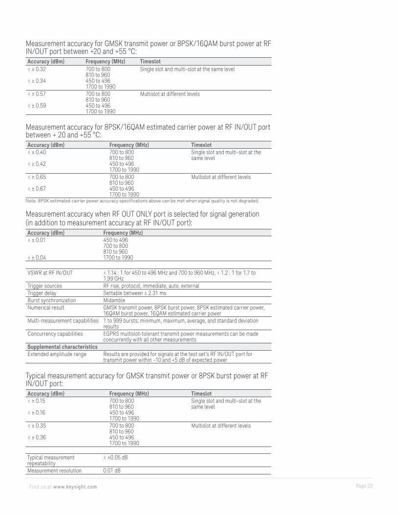
Measurement accuracy for GMSK transmit power or 8PSK/16QAM burst power at RF IN/OUT port between +20 and +55 °C:Accuracy (dBm) Frequency (MHz) Timeslot< ± 0.32
< ± 0.34
700 to 800810 to 960450 to 4961700 to 1990
Single slot and multi-slot at the same level
< ± 0.57
< ± 0.59
700 to 800810 to 960450 to 4961700 to 1990
Multislot at different levels
Measurement accuracy for 8PSK/16QAM estimated carrier power at RF IN/OUT port between + 20 and +55 °C:Accuracy (dBm) Frequency (MHz) Timeslot< ± 0.40
< ± 0.42
700 to 800810 to 960450 to 4961700 to 1990
Single slot and multi-slot at the same level
< ± 0.65
< ± 0.67
700 to 800810 to 960450 to 4961700 to 1990
Multislot at different levels
Note: 8PSK estimated carrier power accuracy specifications above can be met when signal quality is not degraded.
Measurement accuracy when RF OUT ONLY port is selected for signal generation (in addition to measurement accuracy at RF IN/OUT port):Accuracy (dBm) Frequency (MHz)< ± 0.01
< ± 0.04
450 to 496700 to 800810 to 9601700 to 1990
VSWR at RF IN/OUT < 1.14 : 1 for 450 to 496 MHz and 700 to 960 MHz, < 1.2 : 1 for 1.7 to 1.99 GHz
Trigger sources RF rise, protocol, immediate, auto, externalTrigger delay Settable between ± 2.31 msBurst synchronization MidambleNumerical result GMSK transmit power, 8PSK burst power, 8PSK estimated carrier power,
16QAM burst power, 16QAM estimated carrier powerMulti-measurement capabilities 1 to 999 bursts; minimum, maximum, average, and standard deviation
resultsConcurrency capabilities EGPRS multislot-tolerant transmit power measurements can be made
concurrently with all other measurementsSupplemental characteristicsExtended amplitude range Results are provided for signals at the test set’s RF IN/OUT port for
transmit power within –10 and +5 dB of expected power
Typical measurement accuracy for GMSK transmit power or 8PSK burst power at RF IN/OUT port:Accuracy (dBm) Frequency (MHz) Timeslot< ± 0.15
< ± 0.16
700 to 800810 to 960450 to 4961700 to 1990
Single slot and multi-slot at the same level
< ± 0.35
< ± 0.36
700 to 800810 to 960450 to 4961700 to 1990
Multislot at different levels
Typical measurement repeatability
< ±0.05 dB
Measurement resolution 0.01 dB
Page 24Find us at www.keysight.com
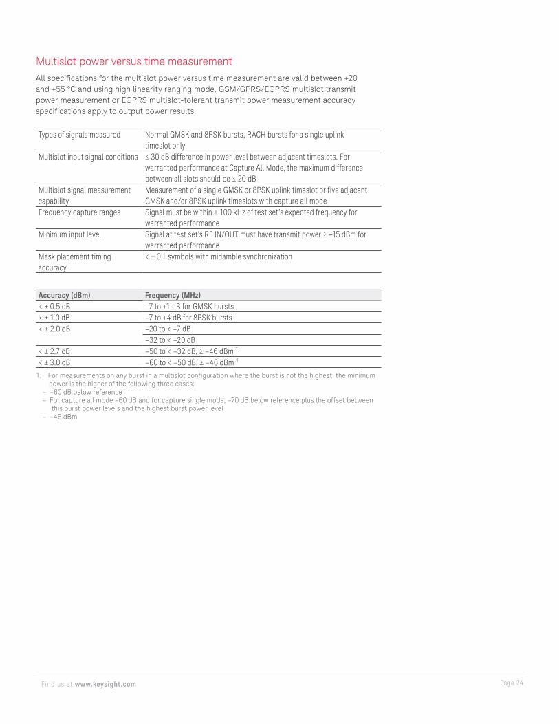
Multislot power versus time measurementAll specifications for the multislot power versus time measurement are valid between +20 and +55 °C and using high linearity ranging mode. GSM/GPRS/EGPRS multislot transmit power measurement or EGPRS multislot-tolerant transmit power measurement accuracy specifications apply to output power results.
Types of signals measured Normal GMSK and 8PSK bursts, RACH bursts for a single uplink timeslot only
Multislot input signal conditions ≤ 30 dB difference in power level between adjacent timeslots. For warranted performance at Capture All Mode, the maximum difference between all slots should be ≤ 20 dB
Multislot signal measurement capability
Measurement of a single GMSK or 8PSK uplink timeslot or five adjacent GMSK and/or 8PSK uplink timeslots with capture all mode
Frequency capture ranges Signal must be within ± 100 kHz of test set’s expected frequency for warranted performance
Minimum input level Signal at test set’s RF IN/OUT must have transmit power ≥ –15 dBm for warranted performance
Mask placement timing accuracy
< ± 0.1 symbols with midamble synchronization
Accuracy (dBm) Frequency (MHz)< ± 0.5 dB –7 to +1 dB for GMSK bursts< ± 1.0 dB –7 to +4 dB for 8PSK bursts< ± 2.0 dB –20 to < –7 dB
–32 to < –20 dB< ± 2.7 dB –50 to < –32 dB, ≥ –46 dBm 1
< ± 3.0 dB –60 to < –50 dB, ≥ –46 dBm 1
1. For measurements on any burst in a multislot configuration where the burst is not the highest, the minimum power is the higher of the following three cases:
– –60 dB below reference – For capture all mode –60 dB and for capture single mode, –70 dB below reference plus the offset between
this burst power levels and the highest burst power level – –46 dBm
Page 25Find us at www.keysight.com
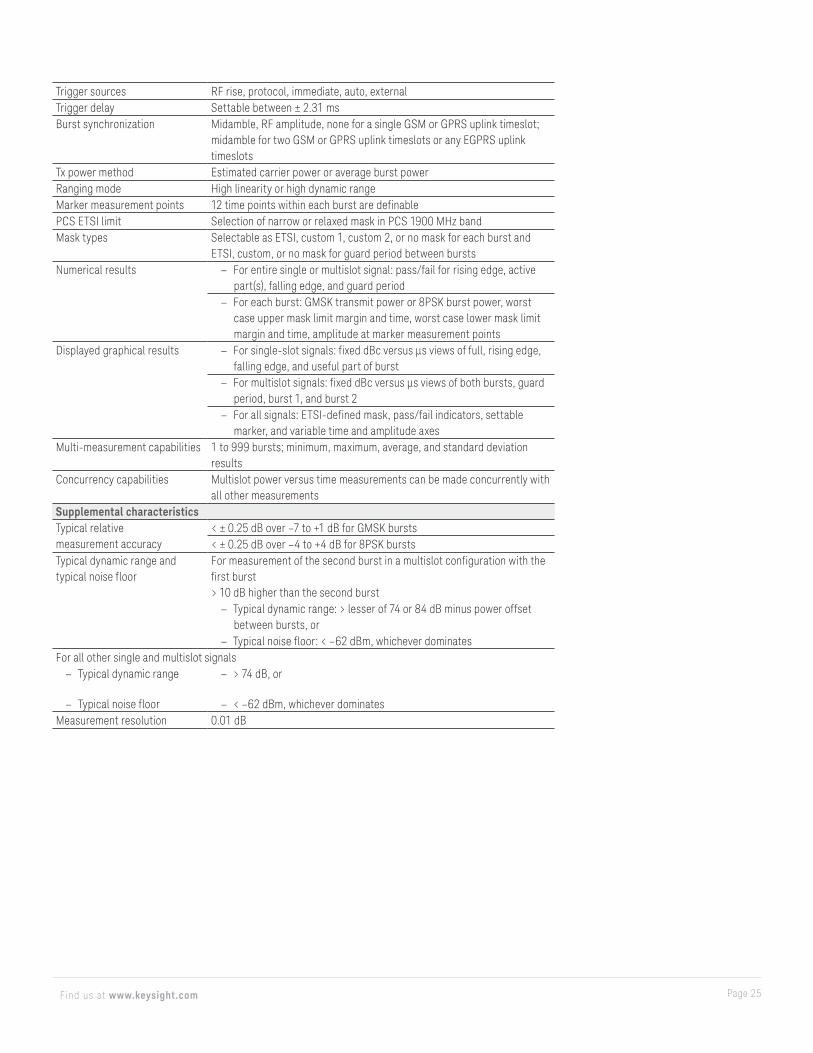
Trigger sources RF rise, protocol, immediate, auto, externalTrigger delay Settable between ± 2.31 msBurst synchronization Midamble, RF amplitude, none for a single GSM or GPRS uplink timeslot;
midamble for two GSM or GPRS uplink timeslots or any EGPRS uplink timeslots
Tx power method Estimated carrier power or average burst powerRanging mode High linearity or high dynamic rangeMarker measurement points 12 time points within each burst are definablePCS ETSI limit Selection of narrow or relaxed mask in PCS 1900 MHz bandMask types Selectable as ETSI, custom 1, custom 2, or no mask for each burst and
ETSI, custom, or no mask for guard period between burstsNumerical results – For entire single or multislot signal: pass/fail for rising edge, active
part(s), falling edge, and guard period – For each burst: GMSK transmit power or 8PSK burst power, worst
case upper mask limit margin and time, worst case lower mask limit margin and time, amplitude at marker measurement points
Displayed graphical results – For single-slot signals: fixed dBc versus μs views of full, rising edge, falling edge, and useful part of burst
– For multislot signals: fixed dBc versus μs views of both bursts, guard period, burst 1, and burst 2
– For all signals: ETSI-defined mask, pass/fail indicators, settable marker, and variable time and amplitude axes
Multi-measurement capabilities 1 to 999 bursts; minimum, maximum, average, and standard deviation results
Concurrency capabilities Multislot power versus time measurements can be made concurrently with all other measurements
Supplemental characteristicsTypical relative measurement accuracy
< ± 0.25 dB over –7 to +1 dB for GMSK bursts< ± 0.25 dB over –4 to +4 dB for 8PSK bursts
Typical dynamic range and typical noise floor
For measurement of the second burst in a multislot configuration with the first burst > 10 dB higher than the second burst
– Typical dynamic range: > lesser of 74 or 84 dB minus power offset between bursts, or
– Typical noise floor: < –62 dBm, whichever dominatesFor all other single and multislot signals
– Typical dynamic range – > 74 dB, or
– Typical noise floor – < –62 dBm, whichever dominatesMeasurement resolution 0.01 dB
Page 26Find us at www.keysight.com
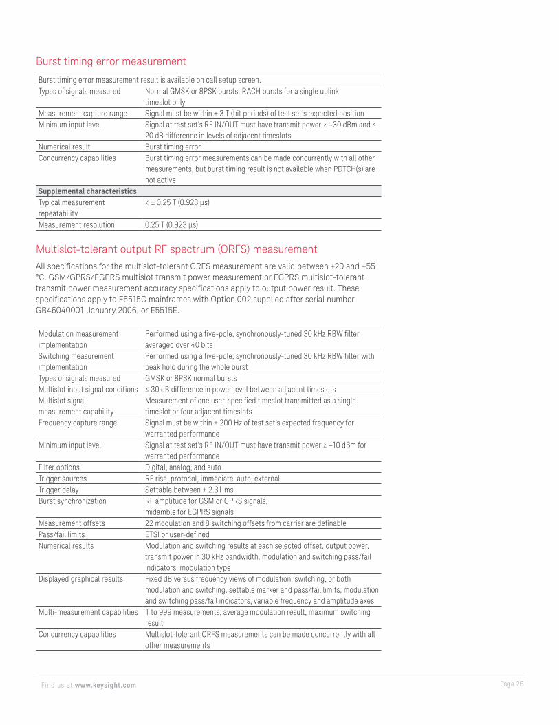
Burst timing error measurement
Burst timing error measurement result is available on call setup screen.Types of signals measured Normal GMSK or 8PSK bursts, RACH bursts for a single uplink
timeslot onlyMeasurement capture range Signal must be within ± 3 T (bit periods) of test set’s expected positionMinimum input level Signal at test set’s RF IN/OUT must have transmit power ≥ –30 dBm and ≤
20 dB difference in levels of adjacent timeslotsNumerical result Burst timing errorConcurrency capabilities Burst timing error measurements can be made concurrently with all other
measurements, but burst timing result is not available when PDTCH(s) are not active
Supplemental characteristicsTypical measurement repeatability
< ± 0.25 T (0.923 μs)
Measurement resolution 0.25 T (0.923 μs)
Multislot-tolerant output RF spectrum (ORFS) measurementAll specifications for the multislot-tolerant ORFS measurement are valid between +20 and +55 °C. GSM/GPRS/EGPRS multislot transmit power measurement or EGPRS multislot-tolerant transmit power measurement accuracy specifications apply to output power result. These specifications apply to E5515C mainframes with Option 002 supplied after serial number GB46040001 January 2006, or E5515E.
Modulation measurement implementation
Performed using a five-pole, synchronously-tuned 30 kHz RBW filter averaged over 40 bits
Switching measurement implementation
Performed using a five-pole, synchronously-tuned 30 kHz RBW filter with peak hold during the whole burst
Types of signals measured GMSK or 8PSK normal burstsMultislot input signal conditions ≤ 30 dB difference in power level between adjacent timeslotsMultislot signal measurement capability
Measurement of one user-specified timeslot transmitted as a single timeslot or four adjacent timeslots
Frequency capture range Signal must be within ± 200 Hz of test set’s expected frequency for warranted performance
Minimum input level Signal at test set’s RF IN/OUT must have transmit power ≥ –10 dBm for warranted performance
Filter options Digital, analog, and autoTrigger sources RF rise, protocol, immediate, auto, externalTrigger delay Settable between ± 2.31 msBurst synchronization RF amplitude for GSM or GPRS signals,
midamble for EGPRS signalsMeasurement offsets 22 modulation and 8 switching offsets from carrier are definablePass/fail limits ETSI or user-definedNumerical results Modulation and switching results at each selected offset, output power,
transmit power in 30 kHz bandwidth, modulation and switching pass/fail indicators, modulation type
Displayed graphical results Fixed dB versus frequency views of modulation, switching, or both modulation and switching, settable marker and pass/fail limits, modulation and switching pass/fail indicators, variable frequency and amplitude axes
Multi-measurement capabilities 1 to 999 measurements; average modulation result, maximum switching result
Concurrency capabilities Multislot-tolerant ORFS measurements can be made concurrently with all other measurements
Page 27Find us at www.keysight.com
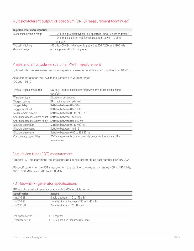
Supplemental characteristicsModulation dynamic range – –74 dBr digital filter-type for full spectrum, power 0 dBm or greater
– –74 dBr analog filter-type for full spectrum, power +10 dBm – or greater
Typical switching dynamic range
–70 dBc/–60 dBm (whichever is greater) at 600, 1200, and 1800 kHz offsets, power +10 dBm or greater
Multislot-tolerant output RF spectrum (ORFS) measurement (continued)
Phase and amplitude versus time (PAvT) measurementOptional PAvT measurement, requires separate license, orderable as part number E1968A-410.
All specifications for the PAvT measurement are valid between +20 and +55 °C.
Types of signals measured CW only – discrete amplitude step waveform or continuous ramp waveform
Waveform type Discrete or continuousTrigger sources RF rise, immediate, externalTrigger delay Settable between 0 to 10 msTrigger threshold Settable between 0 to 30 dBMeasurement timeout Settable between 0.1 to 999.9 sContinuous measurement count Settable between 1 to 5000Continuous measurement delay Settable between 0 to 500 msDiscrete step width Settable between 0.1 to 400 msDiscrete step count Settable between 1 to 512Discrete step center Settable between 0.05 to 399.95 msConcurrency capabilities PAvT measurements cannot be made concurrently with any other
measurements
Fast device tune (FDT) measurementOptional FDT measurement requires separate license, orderable as part number E1999A-202.
All specifications for the FDT measurement are valid for the frequency ranges 450 to 496 MHz, 740 to 960 MHz, and 1700 to 1990 MHz.
FDT (downlink) generator specificationsFDT absolute output level accuracy with GMSK modulation on:
Specification Ranges< ± 2.10 dB Single slot from –110 to –13 dBm< ± 2.10 dB 1 multislot level between –110 and –13 dBm< ± 2.50 dB 2 multislot levels ≤ 20 dB apart
Peak phase error < ± 5 degreesFrequency error < ± 0.02 ppm plus timebase reference
Page 28Find us at www.keysight.com
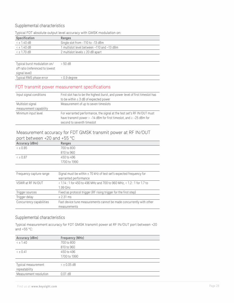
Typical burst modulation on/off ratio (referenced to lowest signal level)
> 50 dB
Typical RMS phase error < 0.9 degree
Supplemental characteristicsTypical FDT absolute output level accuracy with GMSK modulation on:
Specification Ranges< ± 1.40 dB Single slot from –110 to –13 dBm< ± 1.40 dB 1 multislot level between –110 and –13 dBm< ± 1.70 dB 2 multislot levels ≤ 20 dB apart
FDT transmit power measurement specifications
Input signal conditions First slot has to be the highest burst, and power level of first timeslot has to be within ± 3 dB of expected power
Multislot signal measurement capability
Measurement of up to seven timeslots
Minimum input level For warranted performance, the signal at the test set’s RF IN/OUT must have transmit power > –14 dBm for first timeslot, and ≥ –25 dBm for second to seventh timeslot
Measurement accuracy for FDT GMSK transmit power at RF IN/OUT port between +20 and +55 °CAccuracy (dBm) Ranges< ± 0.85 700 to 800
810 to 960< ± 0.87 450 to 496
1700 to 1990
Frequency capture range Signal must be within ± 70 kHz of test set’s expected frequency for warranted performance
VSWR at RF IN/OUT < 1.14 : 1 for 450 to 496 MHz and 700 to 960 MHz, < 1.2 : 1 for 1.7 to 1.99 GHz
Trigger sources Fixed as protocol trigger (RF rising trigger for the first step)Trigger delay ± 2.31 msConcurrency capabilities Fast device tune measurements cannot be made concurrently with other
measurements
Supplemental characteristicsTypical measurement accuracy for FDT GMSK transmit power at RF IN/OUT port between +20 and +55 °C:
Accuracy (dBm) Frequency (MHz)< ± 1.40 700 to 800
810 to 960< ± 0.41 450 to 496
1700 to 1990
Typical measurement repeatability
< ± 0.05 dB
Measurement resolution 0.01 dB
Page 29Find us at www.keysight.com
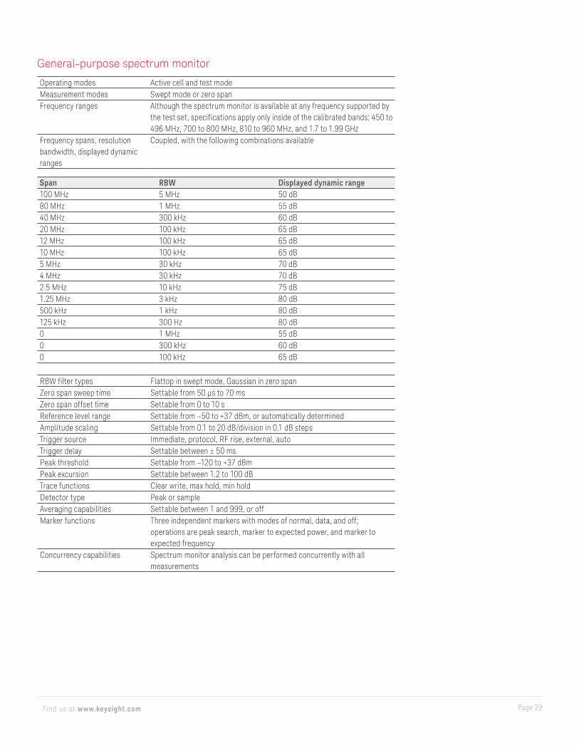
General-purpose spectrum monitor
Operating modes Active cell and test modeMeasurement modes Swept mode or zero spanFrequency ranges Although the spectrum monitor is available at any frequency supported by
the test set, specifications apply only inside of the calibrated bands: 450 to 496 MHz, 700 to 800 MHz, 810 to 960 MHz, and 1.7 to 1.99 GHz
Frequency spans, resolution bandwidth, displayed dynamic ranges
Coupled, with the following combinations available
Span RBW Displayed dynamic range100 MHz 5 MHz 50 dB80 MHz 1 MHz 55 dB40 MHz 300 kHz 60 dB20 MHz 100 kHz 65 dB12 MHz 100 kHz 65 dB10 MHz 100 kHz 65 dB5 MHz 30 kHz 70 dB4 MHz 30 kHz 70 dB2.5 MHz 10 kHz 75 dB1.25 MHz 3 kHz 80 dB500 kHz 1 kHz 80 dB125 kHz 300 Hz 80 dB0 1 MHz 55 dB0 300 kHz 60 dB0 100 kHz 65 dB
RBW filter types Flattop in swept mode, Gaussian in zero spanZero span sweep time Settable from 50 μs to 70 msZero span offset time Settable from 0 to 10 sReference level range Settable from –50 to +37 dBm, or automatically determinedAmplitude scaling Settable from 0.1 to 20 dB/division in 0.1 dB stepsTrigger source Immediate, protocol, RF rise, external, autoTrigger delay Settable between ± 50 msPeak threshold Settable from –120 to +37 dBmPeak excursion Settable between 1.2 to 100 dBTrace functions Clear write, max hold, min holdDetector type Peak or sampleAveraging capabilities Settable between 1 and 999, or offMarker functions Three independent markers with modes of normal, data, and off;
operations are peak search, marker to expected power, and marker to expected frequency
Concurrency capabilities Spectrum monitor analysis can be performed concurrently with all measurements

Page 30Find us at www.keysight.com
Supplemental characteristicsTypical level accuracy:
– < ± 2 dB for signals within 50 dB of a reference level ≥ –10 dBm and RBW < 5 MHz – < ± 2 dB for signals within 30 dB of a reference level < –10 dBm and RBW = 5 MHz using
5 averages – < ± 3.5 dB for signals > –70 dBm and within 50 dB of a reference level < –10 dBm with
RBW < 5 MHz
Displayed average noise level < –90 dBm for reference level of –40 dBm and 30 kHz bandwidthTypical residual responses < –70 dB with input terminated, reference level of –10 dBm and RF
generator power < –80 dBmTypical spurious responses < –50 dBc with expected frequency tuned to carrier, carrier > 420 MHz,
signal and reference level at –10 dBm and all spectral components within 100 MHz of carrier
Frequency resolution 1 HzMarker amplitude resolution 0.01 dB
GSM decoded audio level measurementThe MS needs to be stimulated with a pulsed audio signal at a 10 Hz rate with 50 percent duty cycle for the decoded audio level measurement to provide accurate results.
Types of signals measured Encoded audio present on uplink TCHMeasurement range 200 Hz to 3.6 kHzMeasurement accuracy Observed inaccuracies are due to MS encoder errors since the algorithm in
the test set contributes no bit errorsBand pass filter capabilities 100 Hz bandwidth, tunable from 200 Hz to 3.6 kHz, selectable as on or offMeasurement trigger source ImmediateMeasurement synchronization None requiredNumerical result rms audio levelMulti-measurement capabilities 1 to 999 measurements; average, minimum, maximum, and standard
deviation resultsConcurrency capabilities GSM decoded audio level measurements cannot be made concurrently
with GSM BER or GSM FBER measurements; GSM decoded audio level measurements can be made concurrently with all other measurements
Supplemental characteristicsMeasurement resolution 0.01 percent
Page 31Find us at www.keysight.com
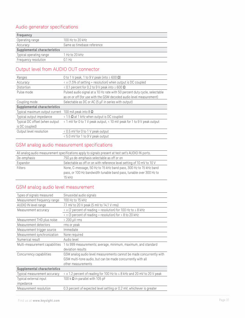
Audio generator specifications
FrequencyOperating range 100 Hz to 20 kHzAccuracy Same as timebase referenceSupplemental characteristicsTypical operating range 1 Hz to 20 kHzFrequency resolution 0.1 Hz
Output level from AUDIO OUT connector
Ranges 0 to 1 V peak, 1 to 9 V peak (into ≥ 600 Ω)Accuracy < ± (1.5% of setting + resolution) when output is DC coupledDistortion < 0.1 percent for 0.2 to 9 V peak into ≥ 600 ΩPulse mode Pulsed audio signal at a 10 Hz rate with 50 percent duty cycle, selectable
as on or off (for use with the GSM decoded audio level measurement)Coupling mode Selectable as DC or AC (5 μF in series with output)Supplemental characteristicsTypical maximum output current 100 mA peak into 8 ΩTypical output impedance < 1.5 Ω at 1 kHz when output is DC coupledTypical DC offset (when output is DC coupled)
< 1 mV for 0 to 1 V peak output, < 10 mV peak for 1 to 9 V peak output
Output level resolution < 0.5 mV for 0 to 1 V peak output< 5.0 mV for 1 to 9 V peak output
GSM analog audio level measurement
Types of signals measured Sinusoidal audio signalsMeasurement frequency range 100 Hz to 15 kHzAUDIO IN level range 7.1 mV to 20 V peak (5 mV to 14.1 V rms)Measurement accuracy < ± (2 percent of reading + resolution) for 100 Hz to ≤ 8 kHz
< ± (3 percent of reading + resolution) for > 8 to 20 kHzMeasurement THD plus noise < 200 μV rmsMeasurement detectors rms or peakMeasurement trigger source ImmediateMeasurement synchronization None requiredNumerical result Audio levelMulti-measurement capabilities 1 to 999 measurements; average, minimum, maximum, and standard
deviation resultsConcurrency capabilities GSM analog audio level measurements cannot be made concurrently with
GSM multi-tone audio, but can be made concurrently with allother measurements
Supplemental characteristicsTypical measurement accuracy < ± 1.2 percent of reading for 100 Hz to ≤ 8 kHz and 20 mV to 20 V peakTypical external input impedance
100 k Ω in parallel with 105 pF
Measurement resolution 0.3 percent of expected level setting or 0.2 mV, whichever is greater
GSM analog audio measurement specifications
All analog audio measurement specifications apply to signals present at test set’s AUDIO IN ports.De-emphasis 750 μs de-emphasis selectable as off or onExpandor Selectable as off or on with reference level setting of 10 mV to 10 VFilters None, C-message, 50 Hz to 15 kHz band pass, 300 Hz to 15 kHz band
pass, or 100 Hz bandwidth tunable band pass, tunable over 300 Hz to15 kHz
Page 32Find us at www.keysight.com
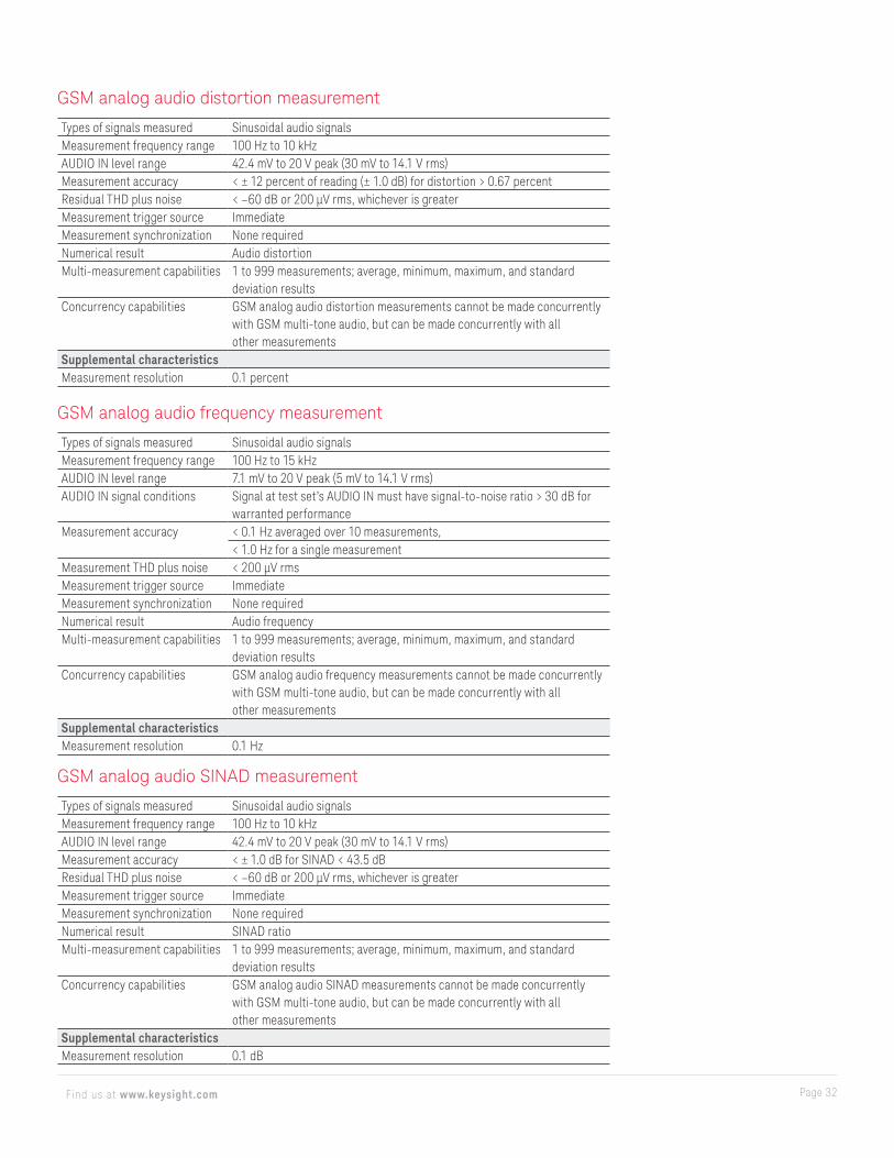
GSM analog audio distortion measurement
Types of signals measured Sinusoidal audio signalsMeasurement frequency range 100 Hz to 10 kHzAUDIO IN level range 42.4 mV to 20 V peak (30 mV to 14.1 V rms)Measurement accuracy < ± 12 percent of reading (± 1.0 dB) for distortion > 0.67 percentResidual THD plus noise < –60 dB or 200 μV rms, whichever is greaterMeasurement trigger source ImmediateMeasurement synchronization None requiredNumerical result Audio distortionMulti-measurement capabilities 1 to 999 measurements; average, minimum, maximum, and standard
deviation resultsConcurrency capabilities GSM analog audio distortion measurements cannot be made concurrently
with GSM multi-tone audio, but can be made concurrently with all other measurements
Supplemental characteristicsMeasurement resolution 0.1 percent
GSM analog audio SINAD measurement
Types of signals measured Sinusoidal audio signalsMeasurement frequency range 100 Hz to 10 kHzAUDIO IN level range 42.4 mV to 20 V peak (30 mV to 14.1 V rms)Measurement accuracy < ± 1.0 dB for SINAD < 43.5 dBResidual THD plus noise < –60 dB or 200 μV rms, whichever is greaterMeasurement trigger source ImmediateMeasurement synchronization None requiredNumerical result SINAD ratioMulti-measurement capabilities 1 to 999 measurements; average, minimum, maximum, and standard
deviation resultsConcurrency capabilities GSM analog audio SINAD measurements cannot be made concurrently
with GSM multi-tone audio, but can be made concurrently with all other measurements
Supplemental characteristicsMeasurement resolution 0.1 dB
GSM analog audio frequency measurement
Types of signals measured Sinusoidal audio signalsMeasurement frequency range 100 Hz to 15 kHzAUDIO IN level range 7.1 mV to 20 V peak (5 mV to 14.1 V rms)AUDIO IN signal conditions Signal at test set’s AUDIO IN must have signal-to-noise ratio > 30 dB for
warranted performanceMeasurement accuracy < 0.1 Hz averaged over 10 measurements,
< 1.0 Hz for a single measurementMeasurement THD plus noise < 200 μV rmsMeasurement trigger source ImmediateMeasurement synchronization None requiredNumerical result Audio frequencyMulti-measurement capabilities 1 to 999 measurements; average, minimum, maximum, and standard
deviation resultsConcurrency capabilities GSM analog audio frequency measurements cannot be made concurrently
with GSM multi-tone audio, but can be made concurrently with all other measurements
Supplemental characteristicsMeasurement resolution 0.1 Hz
Page 33Find us at www.keysight.com
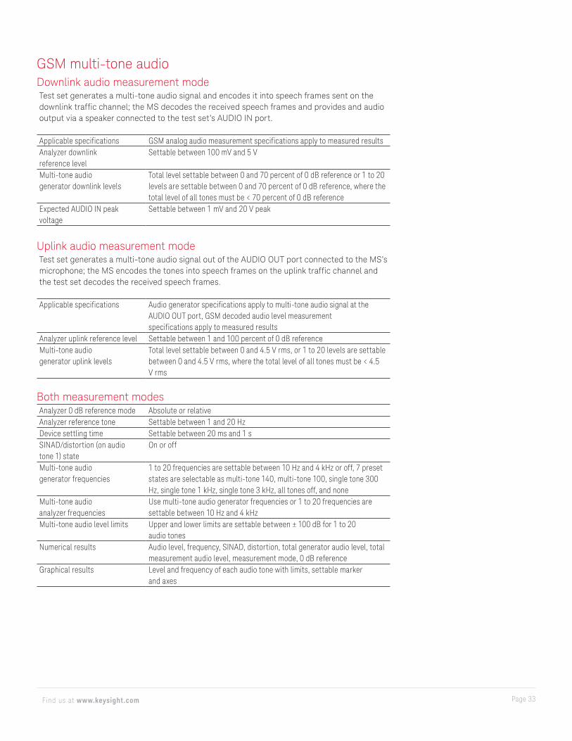
GSM multi-tone audioDownlink audio measurement modeTest set generates a multi-tone audio signal and encodes it into speech frames sent on the downlink traffic channel; the MS decodes the received speech frames and provides and audio output via a speaker connected to the test set’s AUDIO IN port.
Applicable specifications GSM analog audio measurement specifications apply to measured resultsAnalyzer downlink reference level
Settable between 100 mV and 5 V
Multi-tone audio generator downlink levels
Total level settable between 0 and 70 percent of 0 dB reference or 1 to 20 levels are settable between 0 and 70 percent of 0 dB reference, where the total level of all tones must be < 70 percent of 0 dB reference
Expected AUDIO IN peak voltage
Settable between 1 mV and 20 V peak
Uplink audio measurement modeTest set generates a multi-tone audio signal out of the AUDIO OUT port connected to the MS’s microphone; the MS encodes the tones into speech frames on the uplink traffic channel and the test set decodes the received speech frames.
Applicable specifications Audio generator specifications apply to multi-tone audio signal at the AUDIO OUT port, GSM decoded audio level measurement specifications apply to measured results
Analyzer uplink reference level Settable between 1 and 100 percent of 0 dB referenceMulti-tone audio generator uplink levels
Total level settable between 0 and 4.5 V rms, or 1 to 20 levels are settable between 0 and 4.5 V rms, where the total level of all tones must be < 4.5 V rms
Both measurement modesAnalyzer 0 dB reference mode Absolute or relativeAnalyzer reference tone Settable between 1 and 20 HzDevice settling time Settable between 20 ms and 1 sSINAD/distortion (on audio tone 1) state
On or off
Multi-tone audio generator frequencies
1 to 20 frequencies are settable between 10 Hz and 4 kHz or off, 7 preset states are selectable as multi-tone 140, multi-tone 100, single tone 300 Hz, single tone 1 kHz, single tone 3 kHz, all tones off, and none
Multi-tone audio analyzer frequencies
Use multi-tone audio generator frequencies or 1 to 20 frequencies are settable between 10 Hz and 4 kHz
Multi-tone audio level limits Upper and lower limits are settable between ± 100 dB for 1 to 20 audio tones
Numerical results Audio level, frequency, SINAD, distortion, total generator audio level, total measurement audio level, measurement mode, 0 dB reference
Graphical results Level and frequency of each audio tone with limits, settable marker and axes
Page 34Find us at www.keysight.com
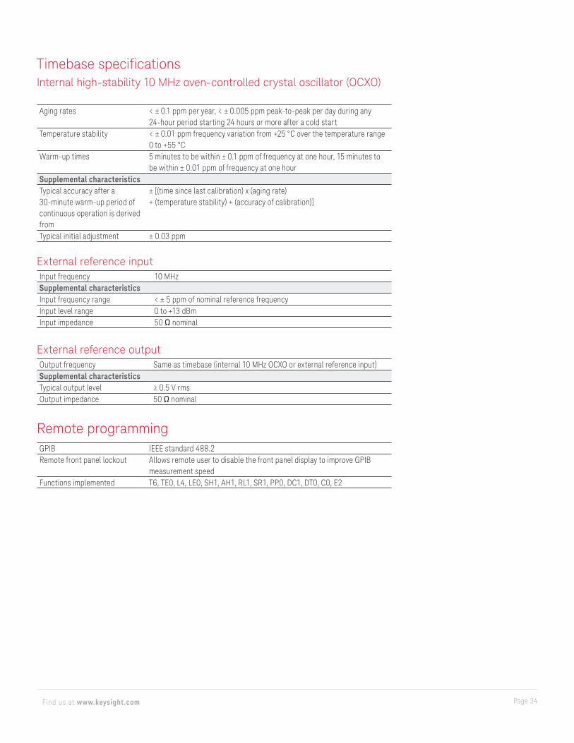
Timebase specificationsInternal high-stability 10 MHz oven-controlled crystal oscillator (OCXO)
Aging rates < ± 0.1 ppm per year, < ± 0.005 ppm peak-to-peak per day during any 24-hour period starting 24 hours or more after a cold start
Temperature stability < ± 0.01 ppm frequency variation from +25 °C over the temperature range 0 to +55 °C
Warm-up times 5 minutes to be within ± 0.1 ppm of frequency at one hour, 15 minutes to be within ± 0.01 ppm of frequency at one hour
Supplemental characteristicsTypical accuracy after a 30-minute warm-up period of continuous operation is derived from
± [(time since last calibration) x (aging rate)+ (temperature stability) + (accuracy of calibration)]
Typical initial adjustment ± 0.03 ppm
External reference inputInput frequency 10 MHzSupplemental characteristicsInput frequency range < ± 5 ppm of nominal reference frequencyInput level range 0 to +13 dBmInput impedance 50 Ω nominal
External reference outputOutput frequency Same as timebase (internal 10 MHz OCXO or external reference input)Supplemental characteristicsTypical output level ≥ 0.5 V rmsOutput impedance 50 Ω nominal
Remote programmingGPIB IEEE standard 488.2Remote front panel lockout Allows remote user to disable the front panel display to improve GPIB
measurement speedFunctions implemented T6, TE0, L4, LE0, SH1, AH1, RL1, SR1, PP0, DC1, DT0, C0, E2

This information is subject to change without notice. © Keysight Technologies, 2012-2019, Published in USA, December 10, 2019, 5990-5708EN
Page 35Find us at www.keysight.com
Learn more at: www.keysight.comFor more information on Keysight Technologies’ products, applications or services,
please contact your local Keysight office. The complete list is available at:
www.keysight.com/find/contactus
Test Subscriber Identification Module (SIM) Cards
Test SIM cards are available for purchase from Keysight Technologies, Inc. Two types are available as follows
– Programmed GSM SIM card micro-size: Fits most current wireless devices (about 15 x 25 mm), part number 08922-61887
– Programmed UMTS SIM card micro-size: Fits most current wireless devices (about 15 x 25 mm), part number E5515-61286
Ordering Information
For current ordering information, please refer to the configuration guide, literature number 5968-7873E, on the Web at www.keysight.com/find/8960
For more information on ordering test SIM cards, visit the Keysight site at www.parts.keysight.com


