616
Agilent Technologies Part no. E4416-90029 Fourth Edition, March 5, 2013 Programming Guide Agilent Technologies EPM-P Series Power Meters

8/9/2019 E4416 Programming Guide
http://slidepdf.com/reader/full/e4416-programming-guide 1/615
Agilent Technologies Part no. E4416-90029
Fourth Edition, March 5, 2013
Programming Guide
Agilent TechnologiesEPM-P Series Power Meters

8/9/2019 E4416 Programming Guide
http://slidepdf.com/reader/full/e4416-programming-guide 2/615
ii EPM-P Series Power Meters Programming Guide
© Copyright 2000–2013 Agilent Technologies
All rights reserved. Reproduction, adaptation, or translation without prior written
permission is prohibited, except as allowed under the copyright laws.
Printed in Malaysia.

8/9/2019 E4416 Programming Guide
http://slidepdf.com/reader/full/e4416-programming-guide 3/615
Equipment Operation
EPM-P Series Power Meters Programming Guide iii
Equipment Operation
Warnings and Cautions
This guide uses warnings and cautions to denote hazards.
WARNING A warning calls attention to a procedure, practice or the like, which, if
not correctly performed or adhered to, could result in injury or the loss
of life. Do not proceed beyond a warning until the indicated conditions
are fully understood and met.
Caution A caution calls attention to a procedure, practice or the like which, if notcorrectly performed or adhered to, could result in damage to or the
destruction of part or all of the equipment. Do not proceed beyond a caution
until the indicated conditions are fully understood and met.
Personal Safety Considerations
WARNING This is a Safety Class I product (provided with a protective earthing
ground incorporated in the power cord). The mains plug shall only be
inserted in a socket outlet provided with a protective earth contact. Any
interruption of the protective conductor, inside or outside the
instrument, is likely to make the instrument dangerous. Intentional
interruption is prohibited.
If this instrument is not used as specified, the protection provided by the
equipment could be impaired. This instrument must be used in a normal
condition (in which all means of protection are intact) only.
No operator serviceable parts inside. Refer servicing to qualified
personnel. To prevent electrical shock, do not remove covers.
For continued protection against fire hazard, replace the line fuse(s)
only with fuses of the same type and rating (for example, normal blow,
time delay, etc.). The use of other fuses or material is prohibited.

8/9/2019 E4416 Programming Guide
http://slidepdf.com/reader/full/e4416-programming-guide 4/615
General Safety Considerations
iv EPM-P Series Power Meters Programming Guide
General Safety Considerations
WARNING Before this instrument is switched on, make sure it has been properlygrounded through the protective conductor of the ac power cable to a
socket outlet provided with protective earth contact.
Any interruption of the protective (grounding) conductor, inside or
outside the instrument, or disconnection of the protective earth terminal
can result in personal injury.
Caution Any adjustments or service procedures that require operation of the
instrument with protective covers removed should be performed only by
trained service personnel.
User Environment
The product is suitable for indoor use only.

8/9/2019 E4416 Programming Guide
http://slidepdf.com/reader/full/e4416-programming-guide 5/615

8/9/2019 E4416 Programming Guide
http://slidepdf.com/reader/full/e4416-programming-guide 6/615
About this Guide
vi EPM-P Series Power Meters Programming Guide
Chapter 9: SENSe Subsystem
This chapter explains how the SENSe command subsystem directly affects device
specific settings used to make measurements.
Chapter 10: STATus Subsystem
This chapter explains how the STATus command subsystem enables you to examine
the status of the power meter by monitoring the “Device Status Register”, “Operation
Status Register” and the “Questionable Status Register”.
Chapter 11: SYSTem Subsystem
This chapter explains how to use the SYSTem command subsystem to return error
numbers and messages from the power meter, preset the power meter, set the GPIBaddress, set the command language and query the SCPI version.
Chapter 12: TRACe Subsystem
This chapter explains how to use the TRACe command subsystem to configure and
read back the measured power trace.
Chapter 13: TRIGger Subsystem
This chapter explains how the TRIGger command subsystem is used synchronizedevice actions with events.
Chapter 14: UNIT Subsystem
This chapter explains how to use the UNIT command subsystem to set the power
meter measurement units to Watts and % (linear), or dBm and dB (logarithmic).
Chapter 15: SERVice Subsystem
This chapter explains how to use the SERVice command subsystem to obtain and setinformation useful for servicing the power meter.
Chapter 16: IEEE488.2 Command Reference
This chapter contains information about the IEEE488.2 Common Commands that the
power meter supports.

8/9/2019 E4416 Programming Guide
http://slidepdf.com/reader/full/e4416-programming-guide 7/615
About this Guide
EPM-P Series Power Meters Programming Guide vii
Appendix A
This appendix contains information about the calibration factor block layout.

8/9/2019 E4416 Programming Guide
http://slidepdf.com/reader/full/e4416-programming-guide 8/615
Related Publications
viii EPM-P Series Power Meters Programming Guide
Related Publications
The EPM-P Series Power Meters User’s Guide is available on the CD-ROM and in
the following languages:
• English Language User’s Guide - Standard
• German Language User’s Guide - Option ABD
• Spanish Language User’s Guide - Option ABE
• French Language User’s Guide - Option ABF
• Italian Language User’s Guide - Option ABZ
• Japanese Language User’s Guide - Option ABJ
Useful information on SCPI (Standard Commands for Programmable Instruments)
can be found in:
• A Beginner’s Guide to SCPI , which is available by ordering Agilent Part
Number 5010-7166.
• The SCPI reference manuals which are available from:
SCPI Consortium,
8380 Hercules Drive, Suite P3,
La Mesa, CA 91942, USA.
Telephone: 619-697-4301 Fax: 619-697-5955

8/9/2019 E4416 Programming Guide
http://slidepdf.com/reader/full/e4416-programming-guide 9/615

8/9/2019 E4416 Programming Guide
http://slidepdf.com/reader/full/e4416-programming-guide 10/615

8/9/2019 E4416 Programming Guide
http://slidepdf.com/reader/full/e4416-programming-guide 11/615

8/9/2019 E4416 Programming Guide
http://slidepdf.com/reader/full/e4416-programming-guide 12/615
8/9/2019 E4416 Programming Guide
http://slidepdf.com/reader/full/e4416-programming-guide 13/615

8/9/2019 E4416 Programming Guide
http://slidepdf.com/reader/full/e4416-programming-guide 14/615

8/9/2019 E4416 Programming Guide
http://slidepdf.com/reader/full/e4416-programming-guide 15/615

8/9/2019 E4416 Programming Guide
http://slidepdf.com/reader/full/e4416-programming-guide 16/615

8/9/2019 E4416 Programming Guide
http://slidepdf.com/reader/full/e4416-programming-guide 17/615

8/9/2019 E4416 Programming Guide
http://slidepdf.com/reader/full/e4416-programming-guide 18/615

8/9/2019 E4416 Programming Guide
http://slidepdf.com/reader/full/e4416-programming-guide 19/615
EPM-P Series Power Meters Programming Guide Contents-11
*CLS ........................................................................................................ 16-6
*DDT <arbitrary block program data>|<string program data> ...............16-7
*ESE <NRf> ........................................................................................... 16-9
*ESR? ...................................................................................................... 16-10
*IDN? ...................................................................................................... 16-11
*OPC ....................................................................................................... 16-12
*OPT? ...................................................................................................... 16-13
*RCL <NRf> ........................................................................................... 16-14
*RST ........................................................................................................ 16-15
*SAV <NRf> ............... ............... ................ ............... ................ ............. 16-16
*SRE <NRf> ........................................................................................... 16-17
*STB? ...................................................................................................... 16-19
*TRG ....................................................................................................... 16-21
*TST? ...................................................................................................... 16-22*WAI ....................................................................................................... 16-23
Calibration Factor Block Layout .....................................................................A-1
Calibration Factor Block Layout............................................................... A-2
Index ..............................................................................................................Index-1

8/9/2019 E4416 Programming Guide
http://slidepdf.com/reader/full/e4416-programming-guide 20/615
Contents-12 EPM-P Series Power Meters Programming Guide
THIS PAGE HAS BEEN INTENTIONALLY LEFT BLANK.

8/9/2019 E4416 Programming Guide
http://slidepdf.com/reader/full/e4416-programming-guide 21/615

8/9/2019 E4416 Programming Guide
http://slidepdf.com/reader/full/e4416-programming-guide 22/615
Tables-2 EPM-P Series Power Meters Programming Guide
0-22 CDMA2000: Power Meter Presets For Secondary Channel Sensors ...11-54
0-23 iDEN: Power Meter Presets..................................................................11-55
0-24 iDEN: Power Meter Presets: Window/Measurement Settings .............11-56
0-25 iDEN: Power Meter Presets For Secondary Channel Sensors..............11-57
0-26 PPD Mapping........................................................................................16-4
0-27 PPE Mapping ........................................................................................16-4
0-28 *ESE Mapping ......................................................................................16-9
0-29 *ESR? Mapping ....................................................................................16-10
0-30 *SRE Mapping......................................................................................16-17
0-31 *STB? Mapping ....................................................................................16-19
8/9/2019 E4416 Programming Guide
http://slidepdf.com/reader/full/e4416-programming-guide 23/615
List of Figures
Page
EPM-P Series Power Meters Programming Guide Figures-1
0-1 Sensor Calibration Tables.......................................................................1-41
0-2 Frequency Dependent Offset Tables ......................................................1-51
0-3 Averaged Readings.................................................................................1-59
0-4 Averaging Range Hysteresis ..................................................................1-59
0-5 Limits Checking Application..................................................................1-63
0-6 Limits Checking Results.........................................................................1-64
0-7 Pulsed Signal ..........................................................................................1-67
0-8 How Measurements are Calculated ........................................................ 1-74
0-9 Generalized Status Register Model ........................................................1-76
0-10 Typical Status Register Bit Changes ......................................................1-77
0-11 Status System.......................................................................................... 1-83
0-12 CALCulate Block ...................................................................................3-2
0-13 Averaged Readings.................................................................................9-8
0-1 A Trace Display Of The Active Timeslots ..........................................11-40
List of Figures
Page

8/9/2019 E4416 Programming Guide
http://slidepdf.com/reader/full/e4416-programming-guide 24/615
Figures-2 EPM-P Series Power Meters Programming Guide
THIS PAGE HAS BEEN INTENTIONALLY LEFT BLANK.

8/9/2019 E4416 Programming Guide
http://slidepdf.com/reader/full/e4416-programming-guide 25/615
1
Power Meter Remote Operation
Power Meter Remote Operation
Introduction

8/9/2019 E4416 Programming Guide
http://slidepdf.com/reader/full/e4416-programming-guide 26/615
1-2 EPM-P Series Power Meters Programming Guide
Introduction
This chapter describes the parameters which configure the power meter and help you
determine settings to optimize performance. It contains the following sections:
“Configuring the Remote Interface”, on page 1-3.
“Zeroing and Calibrating the Power Meter”, on page 1-5.
“Making Measurements”, on page 1-8.
“Making Measurements on Wireless Communication Standards”, on page 1-24
“Using Sensor Calibration Tables”, on page 1-40.
“Using Frequency Dependent Offset Tables”, on page 1-50
“Setting the Range, Resolution and Averaging”, on page 1-57.
“Setting Offsets”, on page 1-61.
“Setting Measurement Limits”, on page 1-63.
“Measuring Pulsed Signals”, on page 1-67.
“END”, on page 1-69.
“Getting the Best Speed Performance”, on page 1-70.
“How Measurements are Calculated”, on page 1-74.
“Status Reporting”, on page 1-75.
“Saving and Recalling Power Meter Configurations”, on page 1-95.
“Using Device Clear to Halt Measurements”, on page 1-96.
“An Introduction to the SCPI Language”, on page 1-97.
“Summary Of Commands”, on page 1-106.
“SCPI Compliance Information”, on page 1-119.

8/9/2019 E4416 Programming Guide
http://slidepdf.com/reader/full/e4416-programming-guide 27/615
Power Meter Remote Operation
Configuring the Remote Interface

8/9/2019 E4416 Programming Guide
http://slidepdf.com/reader/full/e4416-programming-guide 28/615
1-4 EPM-P Series Power Meters Programming Guide
RS232/RS422 Configuration
The RS232/RS422 serial port on the rear panel is a nine pin D-type connector
configured as a DTE (Data Terminal Equipment). For pin-out information and cable
length restrictions refer to the EPM-P Series Power Meters User’s Guide.
You can set the baud rate, word length, parity, number of stop bits, software and
hardware pacing, either remotely or from the front panel. For front panel operation
refer to the EPM-P Series Power Meter User’s Guide. For remote operation use the
following commands:
SYSTem:COMMunicate:SERial:CONTrol:DTRSYSTem:COMMunicate:SERial:CONTrol:RTSSYSTem:COMMunicate:SERial[:RECeive]:BAUD
SYSTem:COMMunicate:SERial[:RECeive]:BITsSYSTem:COMMunicate:SERial[:RECeive]:PACESYSTem:COMMunicate:SERial[:RECeive]:PARity[:TYPE]SYSTem:COMMunicate:SERial[:RECeive]:SBITsSYSTem:COMMunicate:SERIal:TRANsmit:AUTO?SYSTem:COMMunicate:SERial:TRANsmit:BAUDSYSTem:COMMunicate:SERial:TRANsmit:BITsSYSTem:COMMunicate:SERial:TRANsmit:ECHOSYSTem:COMMunicate:SERial:TRANsmit:PACESYSTem:COMMunicate:SERial:TRANsmit:PARity[:TYPE]
SYSTem:COMMunicate:SERial:TRANsmit:SBITs
Power Meter Remote Operation
Zeroing and Calibrating the Power Meter

8/9/2019 E4416 Programming Guide
http://slidepdf.com/reader/full/e4416-programming-guide 29/615
EPM-P Series Power Meters Programming Guide 1-5
Zeroing and Calibrating the Power Meter
This section describes how to zero and calibrate the power meter.
The calibration and zeroing commands are overlapped commands refer to “Using the
Operation Complete Commands”, on page 1-93 to determine when the commands are
complete.
Zeroing
Zeroing adjusts the power meter’s specified channel for a zero power reading with no
power applied to the power sensor.
The command used to zero the power meter is:
CALibration[1|2]:ZERO:AUTO ONCE
The command assumes that there is no power being applied to the sensor. It turns the
power reference oscillator off, then after zeroing, returns the power reference
oscillator to the same state it was in prior to the command being received.
When to Zero?
Zeroing of the power meter is recommended:
• when a 50C change in temperature occurs.
• when you change the power sensor.
• every 24 hours.
• prior to measuring low level signals. For example, 10 dB above the lowest
specified power for your power sensor.
CalibrationCalibration sets the gain of the power meter using a 50 MHz 1 mW calibrator as a
traceable power reference. The power meter’s POWER REF output or a suitable
external reference is used as the signal source for calibration. An essential part of
calibrating is setting the correct reference calibration factor for the power sensor you
are using. The 8480 Series power sensors and N8480 Series power sensors with
Option CFT require you to set the reference calibration factor. All E-Series power
sensors and N8480 Series power sensors (excluding Option CFT) set the reference
calibration factor automatically. Offset, relative and duty cycle settings are ignored
during calibration.
Power Meter Remote Operation
Zeroing and Calibrating the Power Meter

8/9/2019 E4416 Programming Guide
http://slidepdf.com/reader/full/e4416-programming-guide 30/615
1-6 EPM-P Series Power Meters Programming Guide
The command used to calibrate the power meter is:
CALibration[1|2]:AUTO ONCE
The command assumes that the power sensor is connected to a 1 mW reference
signal. It turns the power reference oscillator on, then after calibrating, returns the
power reference oscillator to the same state it was in prior to the command being
received. It is recommended that you zero the power meter before calibrating.
Calibration Sequence
This feature allows you to perform a complete calibration sequence with a single
query. The query is:
CALibration[1|2][:ALL]?
The query assumes that the power sensor is connected to the power reference
oscillator. It turns the power reference oscillator on, then after calibrating, returns the
power reference oscillator to the same state it was in prior to the command being
received. The calibration sequence consists of:
• Zeroing the power meter (CALibration[1|2]:ZERO:AUTO ONCE), and
• calibrating the power meter (CALibration[1|2]:AUTO ONCE).
The query enters a number into the output buffer when the sequence is complete. If
the result is 0 the sequence was successful. If the result is 1 the sequence failed. Referto CALibration[1]|2[:ALL]? on page 4-5 for further information.
Note The CALibration[1|2][:ALL] command is identical to the
CALibration[1|2][:ALL]? query except that no number is returned to
indicate the outcome of the sequence. You can examine the Questionable Status
Register or the error queue to discover if the sequence has passed or failed. Refer
to “Status Reporting”, on page 1-75 for further information.
Power Meter Remote Operation
Zeroing and Calibrating the Power Meter

8/9/2019 E4416 Programming Guide
http://slidepdf.com/reader/full/e4416-programming-guide 31/615
EPM-P Series Power Meters Programming Guide 1-7
Setting the Reference Calibration Factor
All the 8480 Series power sensors and N8480 Series power sensors with Option CFT
require you to set the reference calibration factor. The reference calibration factor can
be set by:
• entering the value into the power meter using the
CALibrate[1|2]:RCFactor command.
• selecting and enabling the sensor calibration table. The reference calibration factor
is automatically set by the power meter using the reference calibration factor stored
in the sensor calibration table. See “Using Sensor Calibration Tables”, on
page 1-40 for further information.
Examples
a) To enter a reference calibration factor of 98.7% for channel A, you should
use the following command:
CAL:RCF 98.7PCT
This overrides any RCF previously set by selecting a sensor calibration table.
b) To automatically set the reference calibration factor, you have to use a sensor
calibration table as described in “Using Sensor Calibration Tables”, on
page 1-40. To select and enable the table use the following commands:
[SENSe[1]]|SENSe2:CORRection:CSET1:SELect <string> [SENSe[1]]|SENSe2:CORRection:CSET1:STATe ON
When the sensor calibration table is selected the RCF from the table
overrides any value previously set.
Querying the Reference Calibration Factor
To determine the current reference calibration factor, use the following command:
CALibration[1|2]:RCFactor?

8/9/2019 E4416 Programming Guide
http://slidepdf.com/reader/full/e4416-programming-guide 32/615
Power Meter Remote Operation
Making Measurements

8/9/2019 E4416 Programming Guide
http://slidepdf.com/reader/full/e4416-programming-guide 33/615
EPM-P Series Power Meters Programming Guide 1-9
Using MEASure?
The simplest way to program the power meter for measurements is by using the
MEASure? query. However, this command does not offer much flexibility. When
you execute the command, the power meter selects the best settings for the requestedconfiguration and immediately performs the measurement. You cannot change any
settings (other than the expected power value, resolution and with the E4417A the
measurement type) before the measurement is taken. This means you cannot fine tune
the measurement, for example, you cannot change the filter length. To make more
flexible and accurate measurements use the CONFIGure command. The
measurement results are sent to the output buffer.MEASure? is a compound
command which is equivalent to an ABORT, followed by a CONFigure, followed by
a READ?.
MEASure? Examples
The following commands show a few examples of how to use the MEASure? query
to make a measurement. It is advisable to read through these examples in order as
they become increasingly more detailed. These examples configure the power meter
for a measurement (as described in each individual example), automatically place the
power meter in the “wait-for-trigger” state, internally trigger the power meter to take
one reading, and then sends the reading to the output buffer.
These examples give an overview of the MEASure? query. For further information
on the MEASure? commands refer to the section “Running H/F 2” starting on
page 2-49.
Example 1 - The Simplest Method
The following commands show the simplest method of making single channel (for
example A or B) measurements. Using MEAS1? will result in an upper window
measurement, and MEAS2? in a lower window measurement. The channel associated
with the window can be set using the source list parameter (see example 2), or will
default as in this example (See also page 1-12).
MEAS1?
specifies window
MEAS2?
Power Meter Remote Operation
Making Measurements
8/9/2019 E4416 Programming Guide
http://slidepdf.com/reader/full/e4416-programming-guide 34/615
1-10 EPM-P Series Power Meters Programming Guide
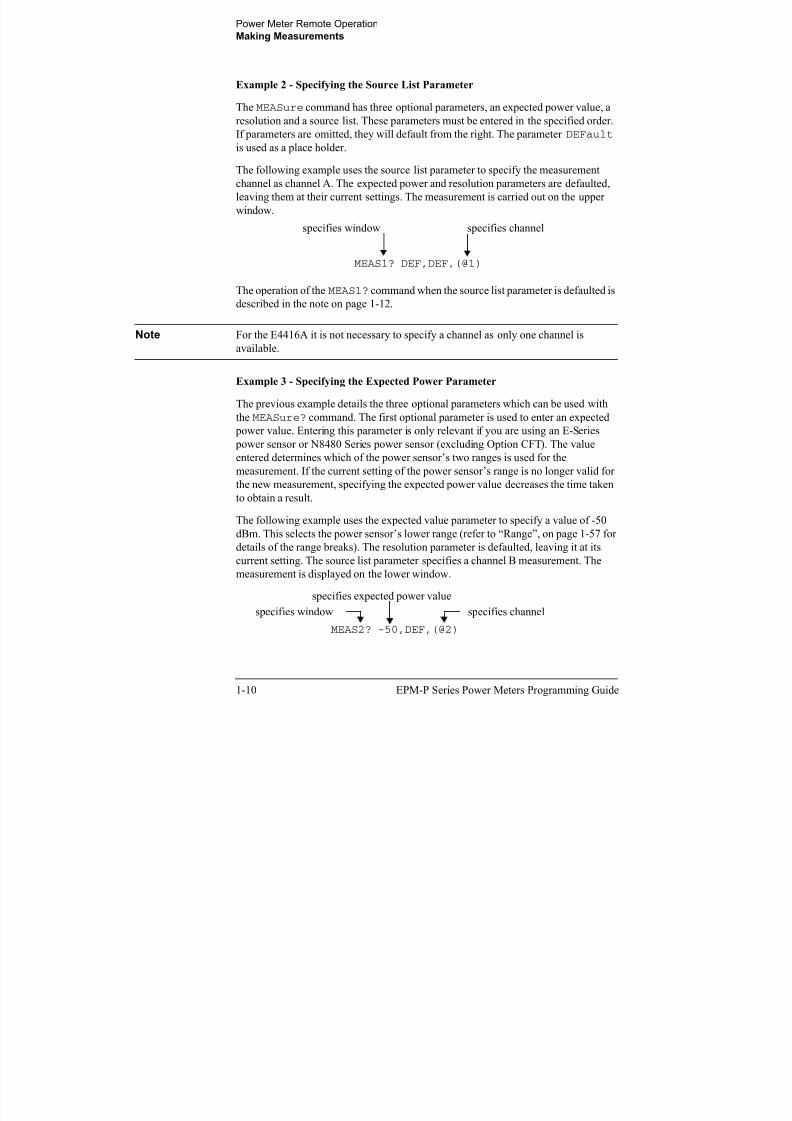
Example 2 - Specifying the Source List Parameter
The MEASure command has three optional parameters, an expected power value, a
resolution and a source list. These parameters must be entered in the specified order.
If parameters are omitted, they will default from the right. The parameter DEFault is used as a place holder.
The following example uses the source list parameter to specify the measurement
channel as channel A. The expected power and resolution parameters are defaulted,
leaving them at their current settings. The measurement is carried out on the upper
window.
The operation of the MEAS1? command when the source list parameter is defaulted is
described in the note on page 1-12.
Note For the E4416A it is not necessary to specify a channel as only one channel is
available.
Example 3 - Specifying the Expected Power Parameter
The previous example details the three optional parameters which can be used with
the MEASure? command. The first optional parameter is used to enter an expected
power value. Entering this parameter is only relevant if you are using an E-Series
power sensor or N8480 Series power sensor (excluding Option CFT). The value
entered determines which of the power sensor’s two ranges is used for the
measurement. If the current setting of the power sensor’s range is no longer valid for
the new measurement, specifying the expected power value decreases the time taken
to obtain a result.
The following example uses the expected value parameter to specify a value of -50dBm. This selects the power sensor’s lower range (refer to “Range”, on page 1-57 for
details of the range breaks). The resolution parameter is defaulted, leaving it at its
current setting. The source list parameter specifies a channel B measurement. The
measurement is displayed on the lower window.
MEAS1? DEF,DEF,(@1)
specifies window specifies channel
MEAS2? -50,DEF,(@2)
specifies window specifies channel
specifies expected power value
Power Meter Remote Operation
Making Measurements

8/9/2019 E4416 Programming Guide
http://slidepdf.com/reader/full/e4416-programming-guide 35/615
EPM-P Series Power Meters Programming Guide 1-11
Example 4 - Specifying the Resolution Parameter
The previous examples detailed the use of the expected value and source list
parameters. The resolution parameter is used to set the resolution of the specified
window. This parameter does not affect the resolution of the GPIB data, however itdoes affect the auto averaging setting (refer to Figure 0-3 on page 1-59).
Since the filter length used for a channel with auto-averaging enabled is dependent on
the window resolution setting, a conflict arises when a given channel is set up in both
windows and the resolution settings are different. In this case, the higher resolution
setting is used to determine the filter length.
The following example uses the resolution parameter to specify a resolution setting of
3. This setting represents 3 significant digits if the measurement suffix is W or %, and
0.01 dB if the suffix is dB or dBm. Refer to Chapter 2, “Measurement Commands” for further details on the resolution parameter. The expected power and source list
parameters are defaulted in the example. The expected power value will be left
unchanged at its current setting. The source list parameter will be defaulted as
described in the note on page 1-12. Note that as the source list parameter is the last
specified parameter you do not have to specify DEF. The measurement is carried out
on the upper window.
Example 5 - Making a Difference Measurement
The following command can only be carried out on the HP EPM-442A. It queries the
lower window to make a difference measurement of channel B - channel A. The
expected power and resolution parameters are defaulted, leaving them at their current
settings.
MEAS1? DEF,3
specifies window specifies resolution setting
MEAS2:POW:AC:DIFF? DEF,DEF,(@2),(@1)
specifies window
specifies between which channels
the difference is calculated
Channel B - A
Power Meter Remote Operation
Making Measurements

8/9/2019 E4416 Programming Guide
http://slidepdf.com/reader/full/e4416-programming-guide 36/615
1-12 EPM-P Series Power Meters Programming Guide
Example 6 - Making a Ratio Measurement
The following command can only be carried out on the E4417A. It queries the upper
window to make a ratio measurement of channel A/B. The expected power and
resolution parameters are defaulted, leaving them at their current settings.
Note E4417A only.
The operation of the MEASure? command when the source list parameter is
defaulted depends on the current setup of the window concerned (for example, A, B,
A/B, A-B etc.) and on the particular command used (for example, MEAS[:POW][:AC]? and MEAS:POW:AC:RAT?).
This means that when the source list parameter is defaulted, there are a number of
possibilities.
Command Current Window Setup Measurement
MEAS1[:POW][AC]? Upper Window: A A
B B
Any Other A
MEAS2[:POW][AC]? Lower Window: A A
B B
Any Other B
MEAS1:POW:AC:RAT Upper Window: A/B A/B
B/A B/A
Any Other A/B
MEAS2:POW:AC:RAT Lower Window: A/B A/B
MEAS1:POW:AC:RAT? DEF,DEF,(@1),(@2)
specifies windowspecifies the relationship of thechannels in the ratio
Channel A / B
Power Meter Remote Operation
Making Measurements

8/9/2019 E4416 Programming Guide
http://slidepdf.com/reader/full/e4416-programming-guide 37/615
EPM-P Series Power Meters Programming Guide 1-13
B/A B/A
Any Other A/B
MEAS1:POW:AC:DIFF? Upper Window: A-B A-B
B-A B-A
Any Other A-B
MEAS2:POW:AC:DIFF? Lower Window: A-B A-B
B-A B-A
Any Other A-B
Command Current Window Setup Measurement
Power Meter Remote Operation
Making Measurements

8/9/2019 E4416 Programming Guide
http://slidepdf.com/reader/full/e4416-programming-guide 38/615
1-14 EPM-P Series Power Meters Programming Guide
Using the CONFigure Command
When you execute this command, the power meter presets the best settings for the
requested configuration (like the MEASure? query). However, the measurement is
not automatically started and you can change measurement parameters before makingmeasurements. This allows you to incrementally change the power meter’s
configuration from the preset conditions. The power meter offers a variety of
low-level commands in the SENSe, CALCulate, and TRIGger subsystems. For
example, if you want to change the averaging use the
[SENSe[1]]|SENSe2:AVERage:COUNt command.
Use the INITiate or READ? query to initiate the measurement.
Using READ?
CONFigure does not take the measurement. One method of obtaining a result is to
use the READ? query. The READ? query takes the measurement using the parameters
set by the CONFigure command then sends the reading to the output buffer. Using
the READ? query will obtain new data.
Using INITiate and FETCh?
CONFigure does not take the measurement. One method of obtaining the result is to
use the INITiate and FETCh? commands. The INITiate command causes the
measurement to be taken. The FETCh? query retrieves a reading when the
measurement is complete, and sends the reading to the output buffer. FETCh? can beused to display the measurement results in a number of different formats (for
example, A/B and B/A) without taking fresh data for each measurement.
CONFigure Examples
The following program segments show how to use the READ? command and the
INITiate and FETCh? commands with CONFigure to make measurements.
It is advisable to read through these examples in order as they become increasingly
more detailed.
These examples give an overview of the CONFigure command. For further
information on the CONFigure commands refer to Chapter 2, “Measurement
Commands”.
Power Meter Remote Operation
Making Measurements

8/9/2019 E4416 Programming Guide
http://slidepdf.com/reader/full/e4416-programming-guide 39/615
EPM-P Series Power Meters Programming Guide 1-15
Example 1 - The Simplest Method
The following program segments show the simplest method of querying the upper
and lower window’s measurement results respectively.
Using READ?
*RST Reset instrument
CONF1 Configure upper window - defaults to a channel A
measurement
READ1? Take upper window (channel A) measurement
*RST Reset instrument
CONF2 Configure the lower window - defaults to channel A (E4416A),
Channel B (E4417A) measurement
READ2? Take lower window measurement (channel A on
E4416A, B on E4417A)
Using INITiate and FETCh?
*RST Reset instrument
CONF1 Configure upper window - defaults to a channel A
measurement
INIT1 Causes channel A to make a measurement
FETC1? Retrieves the upper window’s measurement
For the E4416A only:
*RST Reset instrument
CONF2 Configure lower window - E4416A defaults to
channel A
INIT1? Causes channel A to make measurement
FETC2? Retrieves the lower window’s measurement
For the E4417A only:
*RST Reset instrument CONF2 Configure lower window
INIT2? Causes channel B to make measurement
FETC2? Retrieves the lower window’s measurement
Power Meter Remote Operation
Making Measurements

8/9/2019 E4416 Programming Guide
http://slidepdf.com/reader/full/e4416-programming-guide 40/615
1-16 EPM-P Series Power Meters Programming Guide
Example 2 - Specifying the Source List Parameter
The CONFigure and READ? commands have three optional parameters, an
expected power value, a resolution and a source list. These parameters must be
entered in the specified order. If parameters are omitted, they will default from theright. The parameter DEFault is used as a place holder.
The following examples use the source list parameter to specify the measurement
channel as channel A. The expected power and resolution parameters are defaulted,
leaving them at their current settings. The measurement is carried out on the upper
window.
Although the READ? and FETCh? queries have three optional parameters it is not
necessary to define them as shown in these examples. If they are defined they must be
identical to those defined in the CONFigure command otherwise an error occurs.
Note For the HP EPM-441A it is not necessary to specify a channel as only one
channel is available.
Using READ?
Using INITiate and FETCh?
ABOR1 Aborts channel A
CONF1 DEF,DEF,(@1) Configures the upper window to make a
channel A measurement using the
current expected power and resolution
settings.
READ1? Takes the upper window’s
measurement.
ABOR1 Aborts channel A
CONF1 DEF,DEF,(@1) Configures the upper window to make a
channel A measurement using the
current expected power and resolution
settings.
INIT1 Causes channel A to make a
measurement.
FETC1? Retrieves the upper window’s
measurement.
Power Meter Remote Operation
Making Measurements

8/9/2019 E4416 Programming Guide
http://slidepdf.com/reader/full/e4416-programming-guide 41/615
EPM-P Series Power Meters Programming Guide 1-17
Example 3 - Specifying the Expected Power Parameter
The previous example details the three optional parameters which can be used with
the CONFigure and READ? commands. The first optional parameter is used to enter
an expected power value. Entering this parameter is only relevant if you are using anE-Series power sensor or N8480 Series power sensor (excluding Option CFT). The
value entered determines which of the power sensor’s two ranges is used for the
measurement. If the current setting of the power sensor’s range is no longer valid for
the new measurement, specifying the expected power value decreases the time taken
to obtain a result.
The following example uses the expected value parameter to specify a value of -50
dBm. This selects the power meter’s lower range (refer to “Range”, on page 1-57 for
details of the range breaks). The resolution parameter is defaulted, leaving it at its
current setting. The source list parameter specifies a channel B measurement. Themeasurement is carried out on the upper window.
Using READ?
Some fine tuning of measurements can be carried out using the CONFigure and
READ? commands. For example, in the above program segment some fine tuning can
be carried out by setting the filter length to 1024 and the trigger delay off.
ABOR2
CONF1 -50,DEF,(@2)SENS2:AVER:COUN 1024TRIG2:DEL:AUTO OFFREAD1?
Using INITiate and FETCh?
ABOR2 Aborts channel B
CONF1 -50,DEF,(@2) Configures the upper window to make a
channel B measurement using an
expected power of -50 dBm and the
current resolution setting.READ1? Takes the upper window’s
measurement.
ABOR2 Aborts channel B
Power Meter Remote Operation
Making Measurements

8/9/2019 E4416 Programming Guide
http://slidepdf.com/reader/full/e4416-programming-guide 42/615
1-18 EPM-P Series Power Meters Programming Guide
Some fine tuning of measurements can be carried out using the CONFigure
command and INITiate and FETCh? commands. For example, in the above
program segment some fine tuning can be carried out by setting the filter length to
1024 and the trigger delay off.
ABOR2CONF1 -50,DEF,(@2)SENS2:AVER:COUN 1024TRIG2:DEL:AUTO OFFINIT2FETC1?
CONF1 -50,DEF,(@2) Configures the upper window to make a
channel B measurement using an
expected power of -50 dBm and the
current resolution setting.
INIT2 Causes channel B to make a
measurement.
FETC1? Retrieves the upper window’s
measurement.
Power Meter Remote Operation
Making Measurements

8/9/2019 E4416 Programming Guide
http://slidepdf.com/reader/full/e4416-programming-guide 43/615
EPM-P Series Power Meters Programming Guide 1-19
Example 4 - Specifying the Resolution Parameter
The previous examples detailed the use of the expected value and source list
parameters. The resolution parameter is used to set the resolution of the specified
window. This parameter does not affect the resolution of the GPIB data, however it
does affect the auto averaging setting (refer to Figure 0-3 on page 1-59).
Since the filter length used for a channel with auto-averaging enabled is dependent on
the window resolution setting, a conflict arises when a given channel is set up in both
windows and the resolution settings are different. In this case, the higher resolution
setting is used to determine the filter length.
The following example uses the resolution parameter to specify a resolution setting of
3. This setting represents 3 significant digits if the measurement suffix is W or %, and
0.01 dB if the suffix is dB or dBm (for further details on the resolution parameter refer
to the commands in Chapter 2, “Measurement Commands”). Also, in this example the
expected power and source list parameters are defaulted. The expected power value
will be left unchanged at its current setting. The source list parameter will be
defaulted as described in the note on page 1-12. Note that as the source list parameter
is the last specified parameter you do not have to specify DEF.
Using READ?
Some fine tuning of the above program segment can be carried out for example, by
setting the trigger delay off. The following program segment assumes that channel A
is currently being measured on the upper window.
ABOR1CONF1 DEF,3TRIG1:DEL:AUTO OFFREAD1?
Using INITiate and FETCh?
ABOR1 Aborts channel A.
CONF1 DEF,3 Configures the upper window to make a measurement usingthe current setting of the expected power and source list anda resolution setting of 3.
READ1? Takes the upper window’s measurement. This will be achannel A or B measurement depending on current window
setup
Power Meter Remote Operation
Making Measurements

8/9/2019 E4416 Programming Guide
http://slidepdf.com/reader/full/e4416-programming-guide 44/615
1-20 EPM-P Series Power Meters Programming Guide
The following program segment assumes that channel A is currently being measured
on the upper window.
Some fine tuning of the above program segment can be carried out for example, by
setting the trigger delay off.
ABOR1CONF1 DEF,3TRIG1:DEL:AUTO OFFINIT1:IMMFETC1?
ABOR1 Aborts channel A.
CONF1 DEF,3 Configures the upper window to make a
measurement using the current setting
of the expected power and source list
and a resolution setting of 3.
INIT1 Causes channel A to make a
measurement.
FETC1? Retrieves the upper window’s
measurement.
Power Meter Remote Operation
Making Measurements

8/9/2019 E4416 Programming Guide
http://slidepdf.com/reader/full/e4416-programming-guide 45/615
EPM-P Series Power Meters Programming Guide 1-21
Example 5 - Making a Difference Measurement
The following program segment can be carried out on the HP EPM-442A. It queries
the lower window to make a difference measurement of channel A - channel B. The
expected power level and resolution parameters are defaulted, leaving them at their
current settings. Some fine tuning of the measurement is carried out by setting the
averaging, and the trigger delay to off.
Using READ?
ABOR1ABOR2CONF2:POW:AC:DIFF DEF,DEF,(@1),(@2)SENS1:AVER:COUN 1024SENS2:AVER:COUN 1024
TRIG1:DEL:AUTO OFFTRIG2:DEL:AUTO OFFREAD2:POW:AC:DIFF?READ2:POW:AC:DIFF? DEF,DEF,(@2),(@1)(A second READ? query is sent
to make a channel B - channel A measurement using fresh measurement data.)
Using INITiate and FETCh?
ABOR1ABOR2
CONF2:POW:AC:DIFF DEF,DEF,(@1),(@2)SENS1:AVER:COUN 1024SENS2:AVER:COUN 1024TRIG1:DEL:AUTO OFFTRIG2:DEL:AUTO OFFINIT1:IMMINIT2:IMMFETC2:POW:AC:DIFF?FETC2:POW:AC:DIFF? DEF,DEF,(@2),(@1) (A second FETCh? query is
sent to make a channel B - channel A measurement using the current measurement
data.)
Power Meter Remote Operation
Making Measurements

8/9/2019 E4416 Programming Guide
http://slidepdf.com/reader/full/e4416-programming-guide 46/615
1-22 EPM-P Series Power Meters Programming Guide
Example 6 - Making a Ratio Measurement
The following program segment can be carried out on the HP EPM-442A. It queries
the lower window to make a ratio measurement of channel A/B. The expected power
level and resolution parameters are defaulted, leaving them at their current settings.
Some fine tuning of the measurement is carried out by setting the averaging.
Using READ?
ABOR1ABOR2CONF2:POW:AC:RAT DEF,DEF,(@1),(@2)SENS1:AVER:COUN 512SENS2:AVER:COUN 256READ2:POW:AC:RAT?
READ2:POW:AC:RAT? DEF,DEF,(@2),(@1) (A second READ? query is sentto make a channel B - channel A ratio measurement using fresh measurement data.)
Using INITiate and FETCh?
ABOR1ABOR2CONF2:POW:AC:RAT DEF,DEF,(@1),(@2)SENS1:AVER:COUN 512SENS2:AVER:COUN 256
INIT1:IMMINIT2:IMMFETC2:POW:AC:RAT?FETC2:POW:AC:RAT? DEF,DEF,(@2),(@1) (A second FETCh? query is sent
to make a channel B - channel A measurement using the current measurement data.)
Power Meter Remote Operation
Making Measurements
U i th L L l C d

8/9/2019 E4416 Programming Guide
http://slidepdf.com/reader/full/e4416-programming-guide 47/615
EPM-P Series Power Meters Programming Guide 1-23
Using the Lower Level Commands
An alternative method of making measurements is to use the lower level commands
to set up the expected range and resolution. This can be done using the following
commands:[SENSe[1]]|SENSe2:POWER:AC:RANGeDISPlay[:WINDow[1|2]]:RESolution
The measurement type can be set using the following commands in the CALCulate
subsystem:
CALCulate[1|2]:MATH[:EXPRession]CALCulate[1|2]:RELative[:MAGNitude]
The advantage of using the lower level commands over the CONFigure command is
that they give you more precise control of the power meter. As shown in Table 0-1 on
page 1-8 the CONFigure command presets various states in the power meter. It may
be likely that you do not want to preset these states.
Example
The following example sets the expected power value to -50 dBm and the resolution
setting to 3 using the lower level commands. The measurement is a single channel A
measurement carried out on the lower window.
ABOR1 Aborts channel A.
CALC2:MATH:EXPR "(SENS1)" Displays channel A on lower window.
SENS1:POW:AC:RANG 0 Sets lower range (E-Series sensors and
N8480 Series sensors (excluding
Option CFT) only).
DISP:WIND2:RES 3 Sets the lower window’s resolution to
setting 3.
INIT1 Causes channel A to make a
measurement.
FETC2? Retrieves the lower window’s
measurement.
Power Meter Remote Operation
Making Measurements on Wireless Communication Standards
8/9/2019 E4416 Programming Guide
http://slidepdf.com/reader/full/e4416-programming-guide 48/615
1-24 EPM-P Series Power Meters Programming Guide
Making Measurements on Wireless CommunicationStandards
The following sections describe typical measurements you may want to make. Theyare also described, for front panel operation, in the User’s Guide.
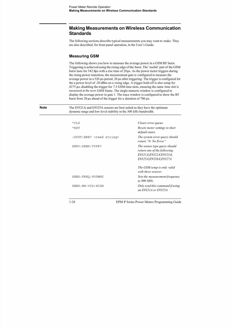
Measuring GSM
The following shows you how to measure the average power in a GSM RF burst.
Triggering is achieved using the rising edge of the burst. The ‘useful’ part of the GSM
burst lasts for 542.8µs with a rise time of 28µs. As the power meter triggers during
the rising power transition, the measurement gate is configured to measure the
average power in a 520 µs period, 20 µs after triggering. The trigger is configured forthe a power level of -20 dBm on a rising edge. A trigger hold off is also setup for
4275 µs, disabling the trigger for 7.5 GSM time slots, ensuring the same time slot is
measured at the next GSM frame. The single numeric window is configured to
display the average power in gate 1. The trace window is configured to show the RF
burst from 20 µs ahead of the trigger for a duration of 700 µs.
Note The E9321A and E9325A sensors are best suited as they have the optimum
dynamic range and low-level stability in the 300 kHz bandwidth.
*CLS Clears error queue
*RST Resets meter settings to their
default states
:SYST:ERR? <read string> The system error query should
return “0: No Error”
SERV:SENS:TYPE? The sensor type query should
return one of the following:
E9321A|E9322A|E9323A|
E9325A|E9326A|E9327A
The GSM setup is only valid
with these sensors
SENS:FREQ:900MHZ Sets the measurement frequency
to 900 MHz
SENS:BW:VID:HIGH Only send this command if using
an E9321A or E9325A
Power Meter Remote Operation
Making Measurements on Wireless Communication Standards
SENS BW VID LOW O l d thi d if i

8/9/2019 E4416 Programming Guide
http://slidepdf.com/reader/full/e4416-programming-guide 49/615
EPM-P Series Power Meters Programming Guide 1-25
Measuring EDGE
Enhanced Data for Global Evolution or Enhanced Data for GSM Evolution is an
enhancement of the GSM standard. The modulation scheme is 8PSK. As Edge does
not have constant amplitude GMSK modulation like GSM, peak-to-average ratio may
be of interest.
The following procedure shows you how to measure the average power in a GSM RF
burst. Triggering is achieved using the rising edge of the burst. The ‘useful’ part of
the GSM burst lasts for 542.8 µs with a rise time of 28 µs. Also, trigger hysteresis is
SENS:BW:VID:LOW Only send this command if using
an E9323A or E9327A
SENS:SWE1:OFFS:TIME:0.00002 Sets gate1 start point to 20 µ s
after the trigger
SENS:SWE1:TIME0.00052 Sets gate1 length to 520 µ s
INIT:CONT ON Puts meter in “wait for trigger”
state
TRIG:SOUR INT Selects internal trigger
TRIG:LEV:AUTO OFF Turn off auto leveling for trigger
TRIG:LEV -20.00DBM Sets trigger level to -20.0 dBm
TRIG:DEL 0.00002 Actual trigger to occur 20 µ s
after trig level detected TRIG:HOLD 0.004275 Sets trigger hold-off to 4.275 ms
DISP:WIND1:TRACE:LOW -35 Sets trace display minimum
power to -35 dBm
DISP:WIND1:TRACE:UPP 20 Sets trace display maximum
power to +20 dBm
SENS:TRAC:OFFS:TIME -0.00004 Trace starts 40 µ s before trigger
point
SENS:TRAC:TIME 0.0007 Trace span set to 700 µ sDISP:WIND1:FORM TRACE Assigns upper window to a trace
display
DISP:WIND2:FORM SNUM Assigns lower window to a
single numeric display
CALC2:FEED1 “POW:AVER ON SWEEP1” Lower window to show average
power using timing defined by
gate1
Power Meter Remote Operation
Making Measurements on Wireless Communication Standards
included to prevent small power transitions during the burst causing re-triggering. As

8/9/2019 E4416 Programming Guide
http://slidepdf.com/reader/full/e4416-programming-guide 50/615
1-26 EPM-P Series Power Meters Programming Guide
included to prevent small power transitions during the burst causing re triggering. As
the power meter triggers during the rising power transition, the measurement gate is
configured to measure the average power in a 520 µs period, 20 µs after triggering.
The display is configured to show the peak and peak-to-average results in the lower
window in numeric format while the upper window shows the power trace starting40 µs before the trigger.
Note The E9321A and E9325A sensors are best suited as they have the optimum
dynamic range and low-level stability in the 300 kHz bandwidth.
*CLS Clears error queue
*RST Resets meter settings to their
default states:SYST:ERR? <read string> The system error query should
return “0: No Error”
SERV:SENS:TYPE? The sensor type query should
return one of the following:
E9321A|E9322A|E9323A|
E9325A|E9326A|E9327A
The EDGE setup is only valid
with these sensors
SENS:FREQ:900MHZ Sets the measurement frequency
to 900 MHz
SENS:BW:VID:HIGH Only send this command if using
an E9321A or E9325A
SENS:BW:VID:LOW Only send this command if using
an E9323A or E9327A
SENS:SWE1:OFFS:TIME:0.00002 Sets gate1 start point to 20 µ s
after the trigger
SENS:SWE1:TIME0.00052 Sets gate1 length to 520 µ s
INIT:CONT ON Puts meter in “wait for trigger”
state
TRIG:SOUR INT Selects internal trigger
TRIG:LEV:AUTO OFF Turn off auto leveling for trigger
TRIG:LEV -20.00DBM Sets trigger level to -20.0 dBm
Power Meter Remote Operation
Making Measurements on Wireless Communication Standards
TRIG:DEL 0 00002 Actual trigger to occur 20 µs
8/9/2019 E4416 Programming Guide
http://slidepdf.com/reader/full/e4416-programming-guide 51/615
EPM-P Series Power Meters Programming Guide 1-27
Measuring NADC
The following procedure shows you how to measure the average power of both active
time slots in NADC or IS-136 ‘full rate’ transmission. This assumes that there are two
time slots in each frame to be measured, for example, time slots 0.
Triggering is achieved using the rising edge of the burst. The measurement gates are
configured to measure the average power in two NADC time slots, separated by two
inactive time slots. The rise time of an NADC TDMA burst is approximately 123.5 µs
TRIG:DEL 0.00002 Actual trigger to occur 20 µ s
after trig level detected
TRIG:HOLD 0.004275 Sets trigger hold-off to 4.275 ms
TRIG:HYST 3.0 Sets Hysteresis to 3 dB
DISP:WIND1:TRACE:LOW -55 Sets trace display minimum
power to -55 dBm
DISP:WIND1:TRACE:UPP 20 Sets trace display maximum
power to +20 dBm
SENS:TRAC:OFFS:TIME -0.00004 Trace starts 40 µ s before trigger
point
SENS:TRAC:TIME 0.0007 Trace span set to 700 µ s
DISP:WIND1:FORM TRACE Assigns upper window to a trace
display
DISP:WIND2:FORM DNUM Assigns lower window to a dual
numeric display
CALC2:FEED1 “POW:AVER ON SWEEP1” Lower window upper display
line to show average power
using timing defined by gate1
CALC4:FEED1 “POW:PTAV ON SWEEP1” Lower window lower display
line to show peak-to-average
ratio using timing defined by
gate1
0 1 2 0 1 2
IS-136 full rate frame
Power Meter Remote Operation
Making Measurements on Wireless Communication Standards
(6bits) and the ‘useful’ part of the burst lasts approximately 6.4 ms. Gate 1 is

8/9/2019 E4416 Programming Guide
http://slidepdf.com/reader/full/e4416-programming-guide 52/615
1-28 EPM-P Series Power Meters Programming Guide
configured to measure the average power in a 6.4ms period, 123.5 µs after triggering.
Gate 2 is configured to measure the average power in a 6.4ms period, 20.123 ms (3
time slots plus rise times) after triggering.
The display is configured to show the Gate 1 and Gate 2 average results in the lower
window in numeric format, while the upper window shows the power trace starting
2 ms before the trigger.
Note The narrow bandwidth of the NADC signal requires only the 30 kHz bandwidth
of the E9321A and E9325A sensors in the Low setting and these are best suited.
Other E9320 sensors may be used in their lowest setting but they provide less
dynamic range and low-level stability.
*CLS Clears error queue
*RST Resets meter settings to their
default states
:SYST:ERR? <read string> The system error query should
return “0: No Error”
SERV:SENS:TYPE? The sensor type query should
return one of the following:
E9321A|E9322A|E9323A|
E9325A|E9326A|E9327A
The NADC setup is only valid
with these sensors
SENS:FREQ:800MHZ Sets the measurement frequency
to 800 MHz
SENS:BW:VID:LOW Select low video bandwidth
SENS:SWE1:OFFS:TIME:0.0001235 Sets gate1 start point to
123.5 µ s after the trigger
SENS:SWE1:TIME0.0064 Sets gate1 length to 6.4 ms
SENS:SWE2:OFFS:TIME:0.020123 Sets gate2 start point to 20.123
ms after the trigger
SENS:SWE2:TIME0.0064 Sets gate2 length to 6.4 ms
INIT:CONT ON Puts meter in “wait for trigger”
state
TRIG:SOUR INT Selects internal trigger
Power Meter Remote Operation
Making Measurements on Wireless Communication Standards
TRIG:LEV:AUTO OFF Turn off auto leveling for trigger

8/9/2019 E4416 Programming Guide
http://slidepdf.com/reader/full/e4416-programming-guide 53/615
EPM-P Series Power Meters Programming Guide 1-29
ff g f gg
TRIG:LEV -20.00DBM Sets trigger level to -20.0 dBm
TRIG:HOLD 0.03 Sets trigger hold-off to 30 ms
DISP:WIND1:TRACE:LOW -35 Sets trace display minimum power to -35 dBm
DISP:WIND1:TRACE:UPP 20 Sets trace display maximum
power to +20 dBm
SENS:TRAC:OFFS:TIME -0.0002 Trace starts 200 µ s before
trigger point
SENS:TRAC:TIME 0.028 Trace span set to 28 ms
DISP:WIND1:FORM TRACE Assigns upper window to a trace
display
DISP:WIND2:FORM DNUM Assigns lower window to a dual
numeric display
CALC2:FEED1 “POW:AVER ON SWEEP1” Lower window upper display
line to show average power
using timing defined by gate1
CALC4:FEED1 “POW:PTAV ON SWEEP2” Lower window lower display
line to show peak-to-average
ratio using timing defined by
gate2
Power Meter Remote Operation
Making Measurements on Wireless Communication Standards
Measuring iDEN

8/9/2019 E4416 Programming Guide
http://slidepdf.com/reader/full/e4416-programming-guide 54/615
1-30 EPM-P Series Power Meters Programming Guide
The following procedure shows you how to measure the average power, the
peak-to-average power ratio in one iDEN training and data pulse, and the average
power in a 90 ms iDEN frame. Triggering is achieved using the rising edge of the
training burst. The trigger is configured for a power level of -30 dBm on a rising
edge. Auto-level triggering may also be used. A trigger hold off is also set up to
ensure the power meter is not
re-triggered by the data pulse following the training pulse. Time gating is used to
measure the average power in the following 15 ms pulse. The display is configured to
show the peak-to-average ratio within the data pulse and the average power in the
entire 90 ms frame on two display lines in the lower window while the upper window
shows the average power in a 15 ms data pulse. All displays are numeric.
Note The narrow bandwidth of the iDEN signal requires only the 30 kHz bandwidth ofthe E9321A and E9325A sensors in the Low setting and these are best suited.
Other E9320 sensors may be used in their lowest setting but they provide less
dynamic range and low-level stability.
*CLS Clears error queue
*RST Resets meter settings to their
default states
:SYST:ERR? <read string> The system error query should
return “0: No Error”
SERV:SENS:TYPE? The sensor type query should
return one of the following:
E9321A|E9322A|E9323A|
E9325A|E9326A|E9327A
The iDEN setup is only valid
with these sensorsSENS:FREQ:800MHZ Sets the measurement frequency
to 800 MHz
SENS:BW:VID:LOW Select low video bandwidth
SENS:SWE1:OFFS:TIME:0.00001 Sets gate1 start point to 10 µ s
after the trigger
SENS:SWE1:TIME0.015 Sets gate1 length to 15 ms
SENS:SWE2:TIME0.090 Sets gate2 length to 90 ms
Power Meter Remote Operation
Making Measurements on Wireless Communication Standards
INIT:CONT ON Puts meter in “wait for trigger”

8/9/2019 E4416 Programming Guide
http://slidepdf.com/reader/full/e4416-programming-guide 55/615
EPM-P Series Power Meters Programming Guide 1-31
state
TRIG:SOUR INT Selects internal trigger
TRIG:LEV:AUTO OFF Turn off auto leveling for trigger
TRIG:LEV -20.00DBM Sets trigger level to -20.0 dBm
TRIG:HOLD 0.02 Sets trigger hold-off to 20 ms
DISP:WIND1:FORM SNUM Assigns upper window to a
single numeric display
DISP:WIND2:FORM DNUM Assigns lower window to a dual
numeric display
CALC1:FEED1 “POW:AVER ON SWEEP1” Upper window to show average
power using timing defined by
gate1
CALC2:FEED1 “POW:PTAV ON SWEEP1” Lower window upper display
line to show peak-to-average
ratio using timing defined by
gate1
CALC4:FEED1 “POW:PTAV ON SWEEP2” Lower window lower display
line to show peak power ratio
using timing defined by gate2
Power Meter Remote Operation
Making Measurements on Wireless Communication Standards
Measuring Bluetooth

8/9/2019 E4416 Programming Guide
http://slidepdf.com/reader/full/e4416-programming-guide 56/615
1-32 EPM-P Series Power Meters Programming Guide
The following procedure shows you how to measure the peak and average power in a
single Bluetooth DH1 data burst. Triggering is achieved using the rising edge of the
burst. The trigger is configured for a power level of -20 dBm on a rising edge. A
trigger hold off is also setup for 650 µs, disabling the trigger until the current time slot
is measured. The measurement gate is configured to measure the peak and average
power in a 366 µs period, 0.2 µs after the trigger. The display is configured to show
the peak and average power in the lower window in numeric format, while the upper
window shows the power trace over 6 time slots starting 50 µs before the trigger.
Note The E9321A and E9325A sensors are best suited. The E9321A and E9325A are
not recommended due to lack of bandwidth.
*CLS Clears error queue
*RST Resets meter settings to their
default states
:SYST:ERR? <read string> The system error query should
return “0: No Error”
SERV:SENS:TYPE? The sensor type query should
return one of the following:
E9322A|E9323A|
E9326A|E9327A
The Bluetooth setup is only valid
with these sensors
SENS:FREQ:2400MHZ Sets the measurement frequency
to 2400 MHz
SENS:BW:VID:HIGH Only send this command if using
an E9322A or E9326A
SENS:SWE1:OFFS:TIME:0.0000002 Sets gate1 start point to 200 ns
after the trigger
SENS:SWE1:TIME0.000366 Sets gate1 length to 366 µ s
INIT:CONT ON Puts meter in “wait for trigger”
state
TRIG:SOUR INT Selects internal trigger
TRIG:LEV:AUTO OFF Turn off auto leveling for trigger
TRIG:LEV -20.00DBM Sets trigger level to -20.0 dBm
Power Meter Remote Operation
Making Measurements on Wireless Communication Standards
TRIG:HOLD 0.00065 Sets trigger hold-off to 4650 µ s
d

8/9/2019 E4416 Programming Guide
http://slidepdf.com/reader/full/e4416-programming-guide 57/615
EPM-P Series Power Meters Programming Guide 1-33
TRIG:HYST 3.0 Sets Hysteresis to 3 dB
DISP:WIND1:TRACE:LOW -35 Sets trace display minimum
power to -35 dBm
DISP:WIND1:TRACE:UPP 20 Sets trace display maximum
power to +20 dBm
SENS:TRAC:OFFS:TIME -0.00001 Trace starts 10 µ s before trigger
point
SENS:TRAC:TIME 0.00065 Trace span set to 650 µ s
DISP:WIND1:FORM TRACE Assigns upper window to a trace
display
DISP:WIND2:FORM DNUM Assigns lower window to a dual
numeric display
CALC2:FEED1 “POW:AVER ON SWEEP1” Lower window upper display
line to show average power
using timing defined by gate1
CALC4:FEED1 “POW:PEAK ON SWEEP1” Lower window lower display
line to show peak power using
timing defined by gate1
Power Meter Remote Operation
Making Measurements on Wireless Communication Standards
Measuring cdmaOne

8/9/2019 E4416 Programming Guide
http://slidepdf.com/reader/full/e4416-programming-guide 58/615
1-34 EPM-P Series Power Meters Programming Guide
The following procedure shows you how to make a continuous measurement on a
cdmaOne signal. Peak and peak-to-average power measurements are made over a
defined and statistically valid number of samples. With gated 10 ms measurements,
corresponding to 200,000 samples, there is less than a 0.01% probability that there are
no peaks above the measured peak value. The trigger is configured for continuous
triggering on a rising edge at -10 dBm. This results in continuously updated results
based on a 10 ms period relating to a position beyond 0.01% on the CCDF curve,
responding to any changes in signal or DUT.
Note The E9322A and E9326A sensors are best suited due to their 1.5 MHz
bandwidth. The E9321A and E9325A are not recommended due to their lack of
bandwidth.
*CLS Clears error queue
*RST Resets meter settings to their
default states
:SYST:ERR? <read string> The system error query should
return “0: No Error”
SERV:SENS:TYPE? The sensor type query should
return one of the following: E9322A|E9323A|
E9326A|E9327A
The cdmaOne setup is only valid
with these sensors
SENS:FREQ:850MHZ Sets the measurement frequency
to 850 MHz
SENS:BW:VID:HIGH Only send this command if using
an E9322A or an E9326A
SENS:SWE1:OFFS:TIME:0 Sets gate1 start point to the
trigger point
SENS:SWE1:TIME 10E-3 Sets gate time to 10 ms
INIT:CONT ON Puts meter in “wait for trigger”
state
TRIG:SOUR INT Selects internal trigger
TRIG:LEV:AUTO OFF Turn off auto leveling for trigger

8/9/2019 E4416 Programming Guide
http://slidepdf.com/reader/full/e4416-programming-guide 59/615
Power Meter Remote Operation
Making Measurements on Wireless Communication Standards
Measuring W-CDMA
Th f ll i d h h k i

8/9/2019 E4416 Programming Guide
http://slidepdf.com/reader/full/e4416-programming-guide 60/615
1-36 EPM-P Series Power Meters Programming Guide
The following procedure shows you how to make a continuous measurement on a
W-CDMA signal. Peak and peak-to-average power measurements are made over a
defined and statistically valid number of samples. With gated 10 ms measurements,
corresponding to 200,000 samples, there is less than a 0.01% probability that there are
no peaks above the measured peak value.The trigger is configured for continuous
triggering on a rising edge at -10 dBm. This results in continuously updated results
based on a 10 ms period relating to a position beyond 0.01% on the CCDF curve,
responding to any changes in signal or DUT.
Note The E9323A and E9327A sensors are best suited due to their 5 MHz bandwidth.
The E9321A, E9322A, E9325A, and E9326A sensors are not recommended due
to their lack of bandwidth (5 MHz required).
*CLS Clears error queue
*RST Resets meter settings to their
default states
:SYST:ERR? <read string> The system error query should
return “0: No Error”
SERV:SENS:TYPE? The sensor type query should
return one of the following:
E9323A| E9327A
The W-CDMA setup is only
valid with these sensors
SENS:FREQ:1900MHZ Sets the measurement frequency
to 1900 MHz
SENS:BW:VID:HIGH Sets the sensor bandwidth to
high
SENS:SWE1:OFFS:TIME:0 Sets gate1 start point to the
trigger point
SENS:SWE1:TIME 10E-3 Sets gate time to 10 ms
INIT:CONT ON Puts meter in “wait for trigger”
state
TRIG:SOUR INT Selects internal trigger
TRIG:LEV:AUTO OFF Turn off auto leveling for trigger
TRIG:LEV -10.00DBM Sets trigger level to -10.0 dBm
Power Meter Remote Operation
Making Measurements on Wireless Communication Standards
DISP:WIND1:FORM SNUM Assigns upper window to a
single numeric display

8/9/2019 E4416 Programming Guide
http://slidepdf.com/reader/full/e4416-programming-guide 61/615
EPM-P Series Power Meters Programming Guide 1-37
g p y
DISP:WIND2:FORM DNUM Assigns lower window to a dual
numeric display
CALC1:FEED1 “POW:AVER” Upper window to show average
power
CALC2:FEED1 “POW:PEAK” Lower window upper display
line to show peak power
CALC4:FEED1 “POW:PTAV” Lower window lower display
line to show peak-to-average
ratio
Power Meter Remote Operation
Making Measurements on Wireless Communication Standards
Measuring cdma2000
The following procedure shows you how to make a continuous measurement on a

8/9/2019 E4416 Programming Guide
http://slidepdf.com/reader/full/e4416-programming-guide 62/615
1-38 EPM-P Series Power Meters Programming Guide
The following procedure shows you how to make a continuous measurement on a
cdma2000 signal. Peak and peak-to-average power measurements are made over a
defined and statistically valid number of samples. With gated 10 ms measurements,
corresponding to 200,000 samples, there is less than a 0.01% probability that there areno peaks above the measured peak value. The trigger is configured for continuous
triggering on a rising edge at -10 dBm. This results in continuously updated results
based on a 10 ms period relating to a position beyond 0.01% on the CCDF curve,
responding to any changes in signal or DUT.
Note The E9323A and E9327A sensors are best suited due to their 5 MHz bandwidth.
The E9321A, E9322A, E9325A, and E9326A sensors are not recommended due
to their lack of bandwidth (5 MHz required).
*CLS Clears error queue
*RST Resets meter settings to their
default states
:SYST:ERR? <read string> The system error query should
return “0: No Error”
SERV:SENS:TYPE? The sensor type query should
return one of the following:
E9323A| E9327A
The cdma2000 setup is only
valid with these sensors
SENS:FREQ:1900MHZ Sets the measurement frequency
to 1900 MHz
SENS:BW:VID:HIGH Sets the sensor bandwidth to
high
SENS:SWE1:OFFS:TIME:0E-6 Sets gate1 start point to the
trigger point
SENS:SWE1:TIME 10E-3 Sets gate time to 10 ms
INIT:CONT ON Puts meter in “wait for trigger”
state
TRIG:SOUR INT Selects internal trigger
TRIG:LEV:AUTO OFF Turn off auto leveling for trigger
TRIG:LEV -10.00DBM Sets trigger level to -10.0 dBm
Power Meter Remote Operation
Making Measurements on Wireless Communication Standards
DISP:WIND1:FORM SNUM Assigns upper window to a
single numeric display

8/9/2019 E4416 Programming Guide
http://slidepdf.com/reader/full/e4416-programming-guide 63/615
EPM-P Series Power Meters Programming Guide 1-39
DISP:WIND2:FORM DNUM Assigns lower window to a dual
numeric display
CALC1:FEED1 “POW:AVER” Upper window to show average
power
CALC2:FEED1 “POW:PEAK” Lower window upper display
line to show peak power
CALC4:FEED1 “POW:PTAV” Lower window lower display
line to show peak-to-average
ratio
Power Meter Remote Operation
Using Sensor Calibration Tables
Using Sensor Calibration Tables

8/9/2019 E4416 Programming Guide
http://slidepdf.com/reader/full/e4416-programming-guide 64/615
1-40 EPM-P Series Power Meters Programming Guide
This section applies to all 8480 Series power sensors and N8480 Series power sensors
with Option CFT. It does not apply to the E-Series power sensors and N8480 Series
power sensors (excluding Option CFT). All E-Series power sensors have their sensorcalibration tables stored in EEPROM which allows frequency and calibration factor
data to be downloaded by the power meter automatically.
This section describes how to use sensor calibration tables. Sensor calibration tables
are used to store the measurement calibration factors, supplied with each power
sensor, in the power meter. These calibration factors are used to correct measurement
results.
Overview
For the 8480 Series power sensors and N8480 Series power sensors with Option CFT,
there are two methods of providing correction data to the power meter depending on
the setting of the [SENSe[1]]|SENSe2:CORRection:CSET1:STATe command. If [SENSe[1]]|SENSe2:CORRection:CSET1:STATe is OFF the
sensor calibration tables are not used. To make a calibrated power measurement when
[SENSe[1]]|SENSe2:CORRection:CSET1:STATe is OFF, perform the
following steps:
1. Zero and calibrate the power meter. Before carrying out the calibration setthe reference calibration factor for the power meter you are using.
2. Set the calibration factor to the value for the frequency of the signal you
want to measure.
3. Make the measurement.
When [SENSe[1]]|SENSe2:CORRection:CSET1:STATe is ON, the sensor
calibration tables are used, providing you with a quick and convenient method for
making power measurements at a range of frequencies using one or more power
sensors. Note that with the sensor calibration table selected, the RCF from the tableoverrides any value previously set. The power meter is capable of storing 20 sensor
calibration tables of 80 frequency points each.
Power Meter Remote Operation
Using Sensor Calibration Tables
Figure 0-1 illustrates how sensor calibration tables operate.
Figure 0-1: Sensor Calibration Tables

8/9/2019 E4416 Programming Guide
http://slidepdf.com/reader/full/e4416-programming-guide 65/615
EPM-P Series Power Meters Programming Guide 1-41
TABLE N
FREQ
FREQ1
.
.
.
.
.
.
.
.
.
.
.
FREQ2
80CFAC
CFAC1
.
.
.
.
.
.
.
.
.
.
.
80
TABLE 1
FREQ
FREQ1
.
.
.
.
.
.
.
.
.
.
.
FREQ2
80CFAC
CFAC1
.
.
.
.
.
.
.
.
.
.
.
CFAC2
80
TABLE 20
FREQ
FREQ1
.
.
.
.
.
.
.
.
.
.
.
FREQ2
80CFAC
CFAC1
.
.
.
.
.
.
.
.
.
.
.
CFAC2
80
CFAC = Calibration Factor
RCF = Reference Calibration Factor
FREQ
FREQ1
.
.
.
.
.
.
.
.
.
.
.
FREQ2
80
CFAC
CFAC1
.
.
.
.
.
.
.
.
.
.
.
CFAC2
80
Frequency of the signal you wantto measure
Calibration Factor used
TABLE SELECTED
to make Measurement.Calculated by the Power Meter using linear interpolation
RCF RCF RCF
CFAC2
RCF Reference Calibration Factorused for Power Meter
Calibration.
Power Meter Remote OperationUsing Sensor Calibration Tables
To use sensor calibration tables you:
1. Edit a sensor calibration table if necessary.

8/9/2019 E4416 Programming Guide
http://slidepdf.com/reader/full/e4416-programming-guide 66/615
1-42 EPM-P Series Power Meters Programming Guide
2. Select the sensor calibration table.
3. Enable the sensor calibration table.
4. Zero and calibrate the power meter. The reference calibration factor used
during the calibration is automatically set by the power meter from the
sensor calibration table.
5. Specify the frequency of the signal you want to measure. The calibration
factor is automatically set by the power meter from the sensor calibration
table.
6. Make the measurement.
Power Meter Remote OperationUsing Sensor Calibration Tables
Editing Sensor Calibration Tables
It is not possible to create any additional sensor calibration tables. However, the 20
i i b di d i h b T d hi

8/9/2019 E4416 Programming Guide
http://slidepdf.com/reader/full/e4416-programming-guide 67/615
EPM-P Series Power Meters Programming Guide 1-43
existing ones can be edited using the MEMory subsystem. To do this:
1. Select one of the existing tables using: MEMory:TABle:SELect <string>.
For information on naming sensor calibration tables see “Naming Sensor
Calibration Tables”, on page 1-46. For information on the current names
which you can select refer to “Listing Sensor Calibration Table Names”, on
page 1-44.
2. Enter the frequency data using:
MEMory:TABle:FREQuency <numeric_value> {,<numeric_value>}
3. Enter the calibration factors using: MEMory:TABle:GAIN <numeric_value> {,<numeric_value>}. The first parameter you enter should be the
reference calibration factor, each subsequent parameter is a calibration factor
in the sensor calibration table. This means that entries in the frequency list
correspond as shown with entries in the calibration factor list.
4. If required, rename the sensor calibration table using: MEMory:TABLe:MOVE <string>,<string>. The first <string>
parameter identifies the existing table name, and the second identifies the
new table name.
Note The legal frequency suffix multipliers are any of the IEEE suffix multipliers, for
example, KHZ, MHZ and GHZ. If no units are specified the power meter
assumes the data is Hz.
PCT is the only legal unit for calibration factors and can be omitted.
Frequency Calibration Factor
Reference Calibration Factor
Frequency 1 Calibration Factor 1
Frequency 2 Calibration Factor 2
" "
Frequency n Calibration Factor n
Power Meter Remote OperationUsing Sensor Calibration Tables
The frequency and calibration data must be within range. Refer to the individual
commands in Chapter 4 for their specified ranges.

8/9/2019 E4416 Programming Guide
http://slidepdf.com/reader/full/e4416-programming-guide 68/615
1-44 EPM-P Series Power Meters Programming Guide
The number of calibration factor points must be one more than the number of
frequency points. This is verified when the sensor calibration table is selectedusing [SENSe[1]]|SENSe2:CORRection:CSET1[:SELect] <string>
Ensure that the frequency points you use cover the frequency range of the signals
you want to measure. If you measure a signal with a frequency outside the
frequency range defined in the sensor calibration table, then the power meter uses
the highest or lowest frequency point in the sensor calibration table to calculate
the calibration factor.
To make subsequent editing of a sensor calibration table simpler, it isrecommended that you retain a copy of your data in a program.
Listing Sensor Calibration Table Names
To list the tables currently stored in the power meter, use the following command:
MEMory:CATalog:TABLe?
Note that all tables are listed, including frequency dependent offset tables.
The power meter returns the data in the form of two numeric parameters and a stringlist representing all the stored tables.
• <numeric_value>,<numeric_value>{,<string>} The first numeric parameter indicates the amount of memory, in bytes, used for
storage of tables. The second parameter indicates the memory, in bytes, available
for tables.
Power Meter Remote OperationUsing Sensor Calibration Tables
Each string parameter returned indicates the name, type and size of a stored sensor
calibration table:
• <string>,<type>,<size>

8/9/2019 E4416 Programming Guide
http://slidepdf.com/reader/full/e4416-programming-guide 69/615
EPM-P Series Power Meters Programming Guide 1-45
g , yp ,The <string>, <type> and <size> are all character data. The <type> is
always TABL. The <size> is displayed in bytes.
For example, a sample of the response may look like:
560,8020,“Sensor_1,TABL,220”,”Sensor_2,TABL,340” ....
The power meter is shipped with a set of predefined sensor calibration tables. The
data in these sensor calibration tables is based on statistical averages for a range of
Agilent Technologies power sensors. These power sensors are:
• DEFAULT1
• 8481A• 8482A2
• 8483A
• 8481D
• 8485A
• R8486A
• Q8486A
• R8486D
• 8487A
For further information on naming sensor calibration tables see “Naming Sensor
Calibration Tables”, on page 1-46.
Note Predefined sensor calibration table is not applicable for N8480 Series power
sensors with Option CFT. Therefore you are required to create a new sensor
calibration table for the sensors when a sensor calibration table is needed.
1. DEFAULT is a sensor calibration table in which the reference calibration factor and
calibration factors are 100%. This sensor calibration table can be used during the
performance testing of the power meter.
2. The 8482B and 8482H power sensors use the same data as the 8482A.
Power Meter Remote OperationUsing Sensor Calibration Tables
Naming Sensor Calibration Tables
To rename a sensor calibration table use:
MEMory:TABLe:MOVE <string>,<string>

8/9/2019 E4416 Programming Guide
http://slidepdf.com/reader/full/e4416-programming-guide 70/615
1-46 EPM-P Series Power Meters Programming Guide
y g , g
The first<string>
parameter identifies the existing table name, and the second
identifies the new table name.
The following rules apply to sensor calibration table names:
a) The sensor calibration table must consist of no more than 12 characters.
b) All characters must be upper or lower case alphabetic characters, or numeric
(0-9), or an underscore (_).
c) No spaces are allowed in the name.
Power Meter Remote OperationUsing Sensor Calibration Tables
Reviewing Table Data
To review the data stored in a sensor calibration table, use the following commands:
• MEMory TABLe SELect "Sense1"

8/9/2019 E4416 Programming Guide
http://slidepdf.com/reader/full/e4416-programming-guide 71/615
EPM-P Series Power Meters Programming Guide 1-47
• MEMory:TABLe:SELect "Sense1" Select the sensor calibration table named “Sense1”.
• MEMory:TABLe:SELect? Query command which returns the name of the currently selected table.
• MEMory:TABLe:FREQuency:POINTs? Query command which returns the number of stored frequency points.
• MEMory:TABLe:FREQuency? Query command which returns the frequencies stored in the sensor calibration
table (in Hz).
• MEMory:TABLe:GAIN[:MAGNitude]:POINTs?
Query command which returns the number of calibration factor points stored in the sensor calibration table.
• MEMory:TABLe:GAIN[:MAGNitude]? Query command which returns the calibration factors stored in the sensor
calibration table. The first point returned is the reference calibration factor.
Modifying Data
If you need to modify the frequency and calibration factor data stored in a sensor
calibration table you need to resend the complete data lists. There are two ways to do
this:
1. If you have retained the original data in a program, edit the program and
resend the data.
2. Use the query commands shown in “Reviewing Table Data”, on page 1-47 to
enter the data into your computer. Edit this data, then resend it.

8/9/2019 E4416 Programming Guide
http://slidepdf.com/reader/full/e4416-programming-guide 72/615
Power Meter Remote OperationUsing Sensor Calibration Tables
Making the Measurement
To make the power measurement, set the power meter for the frequency of the signal
you want to measure. The power meter automatically sets the calibration factor. Use

8/9/2019 E4416 Programming Guide
http://slidepdf.com/reader/full/e4416-programming-guide 73/615
EPM-P Series Power Meters Programming Guide 1-49
either the INITiate,FETCh? or the READ? query to initiate the measurement as
shown in the following program segments:
INITiate Example
ABORt1CONFigure1:POWer:AC DEF,1,(@1)SENS1:CORR:CSET1:SEL "HP8481A"SENS1:CORR:CSET1:STAT ONSENSe1:FREQuency 500KHZINITiate1:IMMediate
FETCh1?
READ? Example
ABORt1CONFigure1:POWer:AC DEF,2,(@1)SENS1:CORR:CSET1:SEL "HP8481A"SENS1:CORR:CSET1:STAT ONSENSe1:FREQuency 500KHZREAD1?
Note If the measurement frequency does not correspond directly to a frequency in the
sensor calibration table, the power meter calculates the calibration factor using
linear interpolation.
If you enter a frequency outside the frequency range defined in the sensor
calibration table, then the power meter uses the highest or lowest frequency point
in the sensor calibration table to set the calibration factor.
To find out the value of the calibration factor being used by the power meter to
make a measurement, use the query command:
[SENSe[1]]|SENSe2:CORRection:CFAC? The response may be an
interpolated value.
To find out the value of the reference calibration factor being used, use the
commands:
CALibration[1|2]:RCFactor?
Power Meter Remote OperationUsing Frequency Dependent Offset Tables
Using Frequency Dependent Offset Tables
This section describes how to use frequency dependent offset tables. Frequency
d d ff bl i h bili f f ff i

8/9/2019 E4416 Programming Guide
http://slidepdf.com/reader/full/e4416-programming-guide 74/615
1-50 EPM-P Series Power Meters Programming Guide
dependent offset tables give you the ability to compensate for frequency effects in
your test setup.
Overview
If the [SENSe[1]]|SENSe2:CORRection:CSET2:STATe command is OFF,
the frequency dependent offset tables are not used. When
[SENSe[1]]|SENSe2:CORRection:CSET2:STATe is ON, the frequency
dependent offset tables are used, providing you with a quick and convenient method
of compensating for your external test setup over a range of frequencies. Note that
when selected, frequency dependent offset correction is IN ADDITION to anycorrection applied for sensor frequency response. The power meter is capable of
storing 10 frequency dependent offset tables of 80 frequency points each.
To use frequency dependent offset tables you:
1. Edit a frequency dependent offset table if necessary.
2. Select the frequency dependent offset table.
3. Enable the frequency dependent offset table.
4. Zero and calibrate the power meter. The reference calibration factor used
during the calibration will be automatically set by the power meter from a
sensor calibration table, if enabled; otherwise it should be entered manually.
5. Specify the frequency of the signal you want to measure. The required offset
is automatically set by the power meter from the frequency dependent offset
table.
6. Make the measurement.
Power Meter Remote OperationUsing Frequency Dependent Offset Tables
Figure 0-2 illustrates how frequency dependent offset tables operate.
Figure 0-2: Frequency Dependent Offset Tables
TABLE NTABLE 1 TABLE 10

8/9/2019 E4416 Programming Guide
http://slidepdf.com/reader/full/e4416-programming-guide 75/615
EPM-P Series Power Meters Programming Guide 1-51
TABLE N
FREQ
FREQ1
.
.
.
.
.
.
.
.
.
.
.
FREQ2
80OFFSET
OFFSET 1
.
.
.
.
.
.
.
.
.
.
.
80
TABLE 1
FREQ
FREQ1
.
.
.
.
.
.
.
.
.
.
.
FREQ2
80OFFSET
OFFSET 1
.
.
.
.
.
.
.
.
.
.
.2
80
TABLE 10
FREQ
FREQ1
.
.
.
.
.
.
.
.
.
.
.
FREQ2
80OFFSET
OFFSET 1
.
.
.
.
.
.
.
.
.
.
.
OFFSET 2
80
OFFSET = Frequency Dependent Offset
FREQ
FREQ1
.
.
.
.
.
.
.
.
.
.
.
FREQ2
80OFFSET
OFFSET 1
.
.
.
.
.
.
.
.
.
.
.
OFFSET 2
80
Frequency of the signal you wantto measure
TABLE SELECTED
OFFSET2
OFFSET
Frequency dependentoffset used to makeMeasurement. Calculated by the Power Meter usinglinear interpolation.

8/9/2019 E4416 Programming Guide
http://slidepdf.com/reader/full/e4416-programming-guide 76/615
Power Meter Remote OperationUsing Frequency Dependent Offset Tables
table to be used with any sensor.
Ensure that the frequency points you use cover the frequency range of the signals
you want to measure. If you measure a signal with a frequency outside the
frequency range defined in the frequency dependent offset table then the power

8/9/2019 E4416 Programming Guide
http://slidepdf.com/reader/full/e4416-programming-guide 77/615
EPM-P Series Power Meters Programming Guide 1-53
frequency range defined in the frequency dependent offset table, then the power
meter uses the highest or lowest frequency point in the table to calculate theoffset.
To make subsequent editing of a frequency dependent offset table simpler, it is
recommended that you retain a copy of your data in a program.
Listing the Frequency Dependent Offset Table Names
To list the frequency dependent offset tables currently stored in the power meter, use
the following command: MEMory:CATalog:TABLe?
Note that all tables are listed; including sensor calibration tables.
The power meter returns the data in the form of two numeric parameters and a string
list representing all stored tables.
• <numeric_value>,<numeric_value>{,<string>} The first numeric parameter indicates the amount of memory, in bytes, used for
storage of tables. The second parameter indicates the memory, in bytes, available
for tables.
Power Meter Remote OperationUsing Frequency Dependent Offset Tables
Each string parameter returned indicates the name, type and size of a stored frequency
dependent offset table:
• <string>,<type>,<size> The <string>, <type> and <size> are all character data. The <type> is

8/9/2019 E4416 Programming Guide
http://slidepdf.com/reader/full/e4416-programming-guide 78/615
1-54 EPM-P Series Power Meters Programming Guide
always TABL. The <size> is displayed in bytes.
For example, a sample of the response may look like:
560,8020,“Offset_1,TABL,220”,”Offset_2,TABL,340” ....
Naming Frequency Dependent Offset Tables
To rename a frequency dependent offset table use:
MEMory:TABLe:MOVE <string>,<string>
The first <string> parameter identifies the existing table name, and the second
identifies the new table name.
The following rules apply to frequency dependent offset table names:
a) Table names use a maximum of 12 characters.
b) All characters must be upper or lower case alphabetic characters, or numeric
(0-9), or an underscore (_).
c) No spaces are allowed in the name.
Reviewing Table Data
To review the data stored in a frequency dependent offset table, use the following
commands:
• MEMory:TABLe:SELect "Offset1" Select the sensor calibration table named “Offset1”.
• MEMory:TABLe:SELect? Query command which returns the name of the currently selected table.
• MEMory:TABLe:FREQuency:POINTs? Query command which returns the number of stored frequency points.
• MEMory:TABLe:FREQuency? Query command which returns the frequencies stored in the frequency dependent
offset table (in Hz).
• MEMory:TABLe:GAIN[:MAGNitude]:POINTs? Query command which returns the number of offset factor points stored in the
frequency dependent offset table.
Power Meter Remote OperationUsing Frequency Dependent Offset Tables
• MEMory:TABLe:GAIN[:MAGNitude]? Query command which returns the offset factors stored in the frequency dependent
offset table.
Modifying Data

8/9/2019 E4416 Programming Guide
http://slidepdf.com/reader/full/e4416-programming-guide 79/615
EPM-P Series Power Meters Programming Guide 1-55
Modifying Data
If you need to modify the frequency and offset factor data stored in a frequency
dependent offset table you need to resend the complete data lists. There are two ways
to do this:
1. If you have retained the original data in a program, edit the program and
resend the data.
2. Use the query commands shown in “Reviewing Table Data”, on page 1-47 to
enter the data into your computer. Edit this data, then resend it.
Selecting a Frequency Dependent Offset Table
After you have created the frequency dependent offset table, you can select it using
the following command:
[SENSe[1]]|SENSe2:CORRection:CSET2[:SELect] <string>
To find out which frequency dependent offset table is currently selected, use the
query:
[SENSe[1]]|SENSe2:CORRection:CSET2[:SELect]?
Enabling A Frequency Dependent Offset Table
To enable the frequency dependent offset table, use the following command:
[SENSe[1]]|SENSe2:CORRection:CSET2:STATe ON
If you set [SENSe[1]]|SENSe2:CORRection:CSET2:STATe to ON and no
frequency dependent offset table is selected error -221, “Settings conflict” occurs.
Making The Measurement
To make the power measurement, set the power meter for the frequency of the signal
you want to measure. The power meter automatically sets the calibration factor. Use
either the INITiate,FETCh? or the READ? query to initiate the measurement as
shown in the following program segments:
Power Meter Remote OperationUsing Frequency Dependent Offset Tables
INITiate Example
ABORt1CONFigure1:POWer:AC DEF,1,(@1)SENS1:CORR:CSET2:SEL "Offset1"SENS1 CORR CSET2 STAT ON

8/9/2019 E4416 Programming Guide
http://slidepdf.com/reader/full/e4416-programming-guide 80/615
1-56 EPM-P Series Power Meters Programming Guide
SENS1:CORR:CSET2:STAT ONSENSe1:FREQuency 500KHZINITiate1:IMMediateFETCh1?
READ? Example
ABORt1CONFigure1:POWer:AC DEF,2,(@1)SENS1:CORR:CSET2:SEL "Offset1"SENS1:CORR:CSET2:STAT ONSENSe1:FREQuency 500KHZREAD1?
Note If the measurement frequency does not correspond directly to a frequency in the
frequency dependent offset table, the power meter calculates the offset using linear
interpolation.
If you enter a frequency outside the frequency range defined in the frequency
dependent offset table, then the power meter uses the highest or lowest frequency
point in the table to set the offset.
To find out the value of the offset being used by the power meter to make a
measurement, use the query command:
SENSe:CORRection:GAIN4|FDOFfset[:INPut][MAGNITUDE]? The
response may be an interpolated value.
Power Meter Remote OperationSetting the Range, Resolution and Averaging
Setting the Range, Resolution and Averaging
This section provides an overview of setting the range, resolution and averaging. For
more detailed information about these features refer to the individual commands in

8/9/2019 E4416 Programming Guide
http://slidepdf.com/reader/full/e4416-programming-guide 81/615
EPM-P Series Power Meters Programming Guide 1-57
Chapter 9.
Range
The power meter has no internal ranges which can be set. The only ranges that can be
set are those of the E-Series power sensors and N8480 Series power sensors
(excluding Option CFT). With an E-Series power sensor or N8480 Series power
sensor (excluding Option CFT), the range can be set either automatically or manually.
Use autoranging when you are not sure of the power level you will be measuring.
Setting the Range
To set the range manually use the following command:
[SENSe[1]]|SENSe2:POWer:AC:RANGe <numeric_value>
If the <numeric_value> is set to:
• 0, the sensor’s lower range is selected. (For example, this range is -70 to
-13.5 dBm for the E4412A power sensor.)
• 1, the sensor’s upper range is selected. (For example, this range is -14.5 to
+20 dBm for the E4412A power sensor.)
For details on the range limits of other E-Series power sensors and N8480 Series
power sensors (excluding Option CFT), refer to the appropriate power sensor manual.
For further information on this command refer to page 9-46.
To enable autoranging use the following command:
[SENSe[1]]|SENSe2:POWer:AC:RANGe:AUTO ON
Use autoranging when you are not sure of the power level you will be measuring.
Power Meter Remote OperationSetting the Range, Resolution and Averaging
Resolution
You can set the window’s resolution using the following command:
DISPlay[:WINDow[1]|2][:NUMeric[1]|2] :RESolution <numeric value>

8/9/2019 E4416 Programming Guide
http://slidepdf.com/reader/full/e4416-programming-guide 82/615
1-58 EPM-P Series Power Meters Programming Guide
:RESolution <numeric_value>
There are four levels of resolution available (1 through 4).
When the measurement suffix is W or % this parameter represents the number of
significant digits. When the measurement suffix is dB or dBM, 1 through 4 represents
1, 0.1, 0.01, and 0.001 dB respectively.
For further information refer to the :RESolution command on page 5-21.
AveragingThe power meter has a digital filter to average power readings. The number of
readings averaged can range from 1 to 1024. This filter is used to reduce noise, obtain
the desired resolution and to reduce the jitter in the measurement results. However,
the time to take the measurement is increased. You can select the filter length or you
can set the power meter to auto filter mode. To enable and disable averaging use the
following command:
[SENSe[1]]|SENSe2:AVERage[:STATe] <boolean>
Auto Averaging Mode
To enable and disable auto filter mode, use the following command:
[SENSe[1]]|SENSe2:AVERage:COUNt:AUTO <boolean>
When the auto filter mode is enabled, the power meter automatically sets the number
of readings averaged together to satisfy the filtering requirements for most power
measurements. The number of readings averaged together depends on the resolution
and the power level currently being measured. Figure 0-3 lists the number of readings
averaged for each range and resolution when the power meter is in auto filter mode.
Note Figure 0-3 applies to 8480 Series sensors only.
Power Meter Remote OperationSetting the Range, Resolution and Averaging
Figure 0-3: Averaged Readings
Minimum Sensor Power 1 2 3 4Resolution Setting

8/9/2019 E4416 Programming Guide
http://slidepdf.com/reader/full/e4416-programming-guide 83/615
EPM-P Series Power Meters Programming Guide 1-59
Figure 0-4 illustrates part of the power sensor dynamic range hysteresis.
Figure 0-4: Averaging Range Hysteresis
10 dB
10 dB
Maximum Sensor Power
P o w e r S e n s o r
D y n a m i c R a n g e
10 dB
10 dB
8 8 128 128 N um b e r of A v e r a g e s
1 1 16 256
1 1 2 32
1 1 1 16
1 1 1 8
Minimum Sensor Power Minimum Sensor Power + 10 dB
Range Hysteresis
10.5 dB9.5 dB
Power Meter Remote OperationSetting the Range, Resolution and Averaging
Filter Length
You specify the filter length using the following command:
[SENSe[1]]|SENSe2:AVERage:COUNt <numeric_value>

8/9/2019 E4416 Programming Guide
http://slidepdf.com/reader/full/e4416-programming-guide 84/615
1-60 EPM-P Series Power Meters Programming Guide
The range of values for the filter length is 1 to 1024. Specifying this commanddisables automatic filter length selection. Increasing the value of the filter length
reduces measurement noise. However, the time to take the measurement is increased.
Power Meter Remote OperationSetting Offsets
Setting Offsets
Channel Offsets

8/9/2019 E4416 Programming Guide
http://slidepdf.com/reader/full/e4416-programming-guide 85/615
EPM-P Series Power Meters Programming Guide 1-61
The power meter can be configured to compensate for signal loss or gain in your test
setup (for example, to compensate for the loss of a 10 dB attenuator). You use the
SENSe command subsystem to configure the power meter. Gain and loss correction
are a coupled system. This means that a gain set by
[SENSe[1]]|SENSe2:CORRection:GAIN2 is represented in the
[SENSe[1]]|SENSe2:CORRection:LOSS2? command. If you enter an
offset value the state is automatically enabled. However it can be enabled and
disabled using either the [SENSe[1]]|SENSe2:CORRection:GAIN2:STATe or [SENSe[1]]|SENSe2:CORRection:LOSS2:STATe commands.
LOSS2 is coupled to GAIN2 by the equation when the default
unit is linear, and when the default is logarithmic.
Note You can only use LOSS2 and GAIN2 for external losses and gains. LOSS1 and
GAIN1 are specifically for calibration factors.
Display Offsets
Display offset values can be entered using the
CALCulate[1|2]:GAIN[:MAGNitude] command.
CALCulate[1|2]:GAIN:STATe must be set to ON to enable the offset value. If
you enter an offset value the state is automatically enabled. On the HP EPM-442A
this offset is applied after any math calculations (refer to Figure 0-8 on page 1-74).
Loss1
Gain-------------=
Gain Loss – =
Power Meter Remote OperationSetting Offsets
Example
The following example program, in HP Basic, details how to use the channel and
display offsets on an E4417A making a channel A/B ratio measurement. The final
result will be:

8/9/2019 E4416 Programming Guide
http://slidepdf.com/reader/full/e4416-programming-guide 86/615
1-62 EPM-P Series Power Meters Programming Guide
10 !Create I/O path name20 ASSIGN @POWER TO 71330 !Clear the power meter’s interface
40 CLEAR @POWER50 !Set the power meter to a known state60 OUTPUT @POWER;"*RST"70 !Configure the Power Meter to make the measurement80 OUTPUT @Power;"CONF:POW:AC:RAT 20DBM,2,(@1),(@2)"90 !Set the measurement units to dBm 100 OUTPUT @POWER;"UNIT:POW DBM"110 !Set the power meter for channel offsets of -10 dB120 OUTPUT @POWER;"SENS1:CORR:GAIN2 -10"130 OUTPUT @POWER;"SENS2:CORR:GAIN2 -10"
140 !Enable the gain correction150 OUTPUT @POWER;"SENS:CORR:GAIN2:STATe ON"160 OUTPUT @POWER;"SENS2:CORR:GAIN2:STATe ON"170 !Set the power meter for a display offset of -20 dB180 OUTPUT @POWER;"CALC1:GAIN -20 DB"190 PRINT "MAKING THE MEASUREMENT"200 !Initiate the measurement210 OUTPUT @Power;"INIT1:IMM"220 OUTPUT @Power;"INIT2:IMM"
230 ! ... and get the result240 OUTPUT @Power;"FETC:POW:AC:RAT? 20DBM,2,(@1),(@2)"250 ENTER @Power;Reading260 !270 PRINT "The measurement result is ";Reading;"dB."280 END
For further information on channel offsets refer to page 9-34. For further information
on display offsets refer to page 3-6.
AdB m 10 –
BdB m 10 – ---------------------------
⎝ ⎠⎛ ⎞ 20 –
⎝ ⎠⎛ ⎞
dB
Power Meter Remote OperationSetting Measurement Limits
Setting Measurement Limits
You can configure the power meter to detect when a measurement is outside of a
predefined upper and/or lower limit value.
Li it i d t di l li b d d b li d t

8/9/2019 E4416 Programming Guide
http://slidepdf.com/reader/full/e4416-programming-guide 87/615
EPM-P Series Power Meters Programming Guide 1-63
Limits are window or measurement display line based and can be applied to power,ratio or difference measurements. In addition, the limits can be set to output a TTL
logic level at the rear panel Rmt I/O port when the predefined limits are exceeded.
Setting Limits
The power meter can be configured to verify the power being measured against an
upper and/or lower limit value. The range of values that can be set for lower and
upper limits is -150.00 dBm to +230.00 dBm. The default upper limit is +90.00 dBm
and the default lower limit is -90.00 dBm.
A typical application for this feature is shown in Figure 0-5.
Figure 0-5: Limits Checking Application
Power Meter
Swept Source
CHANNEL AINPUT
OUT IN OUT
DeviceUnder Test
Power Meter Remote OperationSetting Measurement Limits
Figure 0-6: Limits Checking Results
Amplitude

8/9/2019 E4416 Programming Guide
http://slidepdf.com/reader/full/e4416-programming-guide 88/615
1-64 EPM-P Series Power Meters Programming Guide
Setting Limits
The power meter can be configured to verify the current measurement in any
measurement line against predefined upper and/or lower limit values. The range of
values that can be set for the upper and lower limits and the default values depends on
the measurement units in the currently measurement line - see Table 0-2.
The limits can also be set to output a TTL logic level at the rear panel Rmt I/O port
when the predefined limits are exceeded. You can switch the rear panel TTL outputs
on or off; set the TTL output level to active high or low; and determine whether the
TTL output represents an over limit condition, under limit condition or both. Refer to
Table 0-2: Range of Values for Window Limits
Window
UnitsMax Min
Default
Max Min
dB +200 dB -180 dB 60 dB -120 dB
dBm +230 dBm -150 dBm 90 dBm -90 dBm
% 10.0 Z% 100.0 a% 100.0 M% 100.0 p%
W 100.000 XW 1.000 aW 1.000 MW 1.000 pW
+4 dBm
+10 dBm
Frequency
oo
oo
o
o
o
Fail
Fail
Power Meter Remote OperationSetting Measurement Limits
Chapter 8 “OUTput Subsystem” for TTL output programming commands and to the
EPM-P Series Power Meters User’s Guide for connector and pin-out information.
Checking for Limit Failures
There are two ways to check for limit failures:

8/9/2019 E4416 Programming Guide
http://slidepdf.com/reader/full/e4416-programming-guide 89/615
EPM-P Series Power Meters Programming Guide 1-65
There are two ways to check for limit failures:
1. Use the SENSe:LIMit:FAIL? and SENSe:LIMit:FCOunt?
commands for channel limits or the CALCulate[1|2]:LIMit:FAIL?
and the CALCulate[1|2]:LIMit:FCOunt? for window limits.
2. Use the STATus command subsystem.
Using SENSe and CALCulate
Using SENSe to check the channel limit failures in Figure 0-6 would return the
following results:
Use the equivalent CALCulate commands for checking window limit failures.
Note If TRIGger:DELay:AUTO is set to ON, then the number of failures returned
by SENSe:LIMit:FCOunt? orCALCulate[1|2]:LIMit:FCOunt?will
be affected by the current filter settings.
SENSe:LIMit:FAIL? Returns 1 if there has been 1 or more
limit failures or 0 if there have been
no limit failures. In this case 1 is
returned.
SENSe:LIMit:FCOunt? Returns the total number of limit
failures, in this case 2.
Power Meter Remote OperationSetting Measurement Limits
Using STATus
You can use the STATus subsystem to generate an SRQ to interrupt your program
when a limit failure occurs. This is a more efficient method than using SENSe or
CALCulate, since you do not need to check the limit failures after every power
measurement.

8/9/2019 E4416 Programming Guide
http://slidepdf.com/reader/full/e4416-programming-guide 90/615
1-66 EPM-P Series Power Meters Programming Guide
Refer to “Status Reporting”, on page 1-75 and “STATus Subsystem”, on page 10-2
for further information.
Configuring the TTL Outputs
The TTL Outputs on the rear panel Rmt I/O port can be used to determine when a
predefined limit in either, or both, windows has been exceeded.
Example
The following program segment shows how to use TTL output 1 to indicate when a
measurement is outside the range -30 dBm to -10 dBm. It is assumed that the
measurement has already been set up in the upper window (window 1).
CALC1:LIM:LOW -30 Sets the lower limit for the upper
window to -30 dBm.
CALC1:LIM:UPP -10 Sets the upper limit for the upper
window to -10 dBm.
CALC1:LIM:STAT ON Turns the limits on.
OUTP:TTL1:FEED“CALC1:LIM:LOW,CALC1:LIM:UPP”
Specifies that TTL output 1 should be
asserted when the upper or lower
limit fails on the upper window.
OUTP:TTL1:ACT HIGH Specifies that TTL output 1 should be
active-high.
OUTP:TTL1:STAT ON Activates TTL output 1
Power Meter Remote OperationMeasuring Pulsed Signals
Measuring Pulsed Signals
Note The E-Series E9320 power sensors are best suited for peak and pulse power
measurement However, the E-Series E9300, 8480 or N8480 Series power sensors
can be used.

8/9/2019 E4416 Programming Guide
http://slidepdf.com/reader/full/e4416-programming-guide 91/615
EPM-P Series Power Meters Programming Guide 1-67
can be used.Pulse measurements are not recommended using E-Series E4410 power sensors.
Using Duty Cycle
The following method describes pulse measurement without the use of an E-Series
E9320 power sensor. The measurement result is a mathematical representation of the
pulse power rather than an actual measurement. The power meter measures the
average power of the pulsed input signal and then divides the measurement result bythe duty cycle value to obtain the pulse power reading. The allowable range of values
is 0.001% to 99.999%. The default is 1.000%. A duty cycle value can be set using the
following command:
[SENSe[1]]|SENSe2:CORRection:DCYCle|GAIN3 <numeric_value>
Making the Measurement
An example of a pulsed signal is shown in Figure 0-7.
Figure 0-7: Pulsed SignalPower
Time
B
A
Duty Cycle = A
B
Duty Cycle (%) = A x 100
B

8/9/2019 E4416 Programming Guide
http://slidepdf.com/reader/full/e4416-programming-guide 92/615
Power Meter Remote OperationMeasuring Pulsed Signals
10 !Create I/O path name20 ASSIGN @Power TO 71330 !Clear the Power Meter’s Interface40 CLEAR @Power50 !Set the Power Meter to a known state60 OUTPUT @Power;"*RST"70 !Configure the Power Meter to make the measurement

8/9/2019 E4416 Programming Guide
http://slidepdf.com/reader/full/e4416-programming-guide 93/615
EPM-P Series Power Meters Programming Guide 1-69
80 OUTPUT @Power;"CONF:POW:AC 20DBM,2,(@1)"90 !Set the reference calibration factor for the sensor100 OUTPUT @Power;"CAL:RCF 98.7PCT"110 !Zero and calibrate the power meter120 OUTPUT @Power;"CAL?"130 PRINT "ZEROING AND CALIBRATING THE POWER METER"140 !Verify the outcome150 ENTER @Power;Success160 IF Success=0 THEN
170 !Calibration cycle was successful180 !190 !Set the measurement units to Watts200 OUTPUT @Power;"UNIT:POW WATT"210 !220 !Set the measurement calibration factor for the
sensor230 OUTPUT @Power;"SENS:CORR:CFAC 97.5PCT"240 !Set the power meter for a duty cycle of 16PCT250 OUTPUT @Power;"SENS1:CORR:DCYC 16PCT"
260 !270 !Enable the duty cycle correction280 OUTPUT @Power;"SENS:CORR:DCYC:STAT ON290 PRINT "MAKING THE MEASUREMENT"300 !Initiate the measurement310 OUTPUT @Power;"INIT1:IMM"320 !... and get the result330 OUTPUT @Power;"FETC?"340 ENTER @Power;Reading350 !
360 PRINT "The result is ";Reading*1000;"mW"370 !380 ELSE390 PRINT "THERE WAS A CALIBRATION ERROR!"400 END IF410 PRINT "PROGRAM COMPLETED"420 END
Power Meter Remote Operation
Getting the Best Speed Performance
Getting the Best Speed Performance
This section discusses the factors that influence the speed of operation (number of
readings/sec) of an EPM-P Series power meter.
The following factors are those which have the greatest effect upon measurementd (i ti l d )

8/9/2019 E4416 Programming Guide
http://slidepdf.com/reader/full/e4416-programming-guide 94/615
1-70 EPM-P Series Power Meters Programming Guide
speed (in no particular order):
• The selected measurement rate, i.e. NORMal, DOUBle, FAST.
• The sensor being used.
• The trigger mode (for example, free run, trigger with delay etc.).
• The output format: ASCii or REAL.
• The units used for the measurement.
• The command used to take a measurement.
In addition, in FAST mode there are other influences which are described in “Fast
Mode”, on page 1-73.
The following paragraphs give a brief description of the above factors and how they
are controlled from SCPI.
Measurement Rate
There are three possible speed settings NORMal, DOUBle and FAST. These are setusing the SENSe:MRATe command and can be applied to each channel
independently (E4417A only).
In NORMal and DOUBle modes, full instrument functionality is available and these
settings can be used with all sensors. FAST mode is available only for E-Series
sensors and averaging, limits and ratio/difference math functions are disabled.
Refer to “Specifications” in the EPM-P Series Power Meters User’s Guide to see the
influence of these speed settings on the accuracy and noise performance of the power
meter.
Power Meter Remote Operation
Getting the Best Speed Performance
Sensor
Different measurement rates are achievable depending on the sensor type being used:
Sensor
Measurement Rate
NORMal DOUBle FAST

8/9/2019 E4416 Programming Guide
http://slidepdf.com/reader/full/e4416-programming-guide 95/615
EPM-P Series Power Meters Programming Guide 1-71
Trigger Mode
The power meter has a very flexible triggering system. For simplicity, it can be
described as having three modes:
• Free Run: When a channel is in Free Run, it continuously takes measurements on
this channel. A channel is in free run when INITiate:CONTinuous is set to
ON and TRIGger:SOURce is set to IMMediate.
• Triggered Free Run: When a channel is in Triggered Free Run Continuous Trigger,
it takes a new measurement each time a trigger even is detected. A channel is in
Triggered Free Run Continuous Trigger when INITiate:CONTinuous is set to
ON and TRIGger:SOURce is not set to IMMediate.
• Single Shot: When a channel is in Single Shot, it takes a new measurement when a
trigger event is detected and then returns to the idle state. A channel is in Single
Shot when INITiate:CONTinuous is set to OFF. Note that a measurement
can take several INT/EXT triggers depending on the filter settings. Refer to
TRIGger[1]|2:DELay:AUTO <boolean> in Chapter 13 for further
information.
Note A trigger event can be any of the following:
• The input signal meeting the trigger level criteria.
• Auto-level triggering being used.
NORMal DOUBle FAST
8480 Series and N8480 Series 50 ms 25 ms NA
E-Series E4410, E9300 50 ms 25 ms Up to 400
E-Series E9320,
AVERage only mode50 ms 25 ms Up to 400
E-Series E9320,
NORMal mode 50 ms 25 ms Up to 1000

8/9/2019 E4416 Programming Guide
http://slidepdf.com/reader/full/e4416-programming-guide 96/615
Power Meter Remote Operation
Getting the Best Speed Performance
Command Used
In Free Run mode, FETCh? must be used to return a result.
In other trigger modes, there are a number of commands which can be used, for
example, MEASure?, READ?, FETCh? Note that the MEAS? and READ?
commands are compound commands—they perform a combination of other lowerlevel commands In general the best speed performance is achieved using the low

8/9/2019 E4416 Programming Guide
http://slidepdf.com/reader/full/e4416-programming-guide 97/615
EPM-P Series Power Meters Programming Guide 1-73
level commands. In general, the best speed performance is achieved using the low
level commands directly.
Trigger Count
To get the fastest measurement speed the a TRIG:COUNT must be set to return
multiple measurements for each FETCh command. For average only measurements a
count of 4 is required but 10 is recommended. In normal mode (peak measurements) a
count of 50 is required to attain 1000 readings per second.
Fast Mode
In the highest speed setting, the limiting factor tends to be the speed of the controller
being used to retrieve results from the power meter, and to a certain extent, the
volume of GPIB traffic. The latter can be reduced using the FORMat REAL
command to return results in binary format. The former is a combination of two
factors:
• the hardware platform being used.• the programming environment being used.
Power Meter Remote Operation
How Measurements are Calculated
How Measurements are Calculated
Figure 0-8 details how measurements are calculated. It shows the order in which the
various power meter functions are implemented in the measurement calculation.
Figure 0-8: How Measurements are Calculated
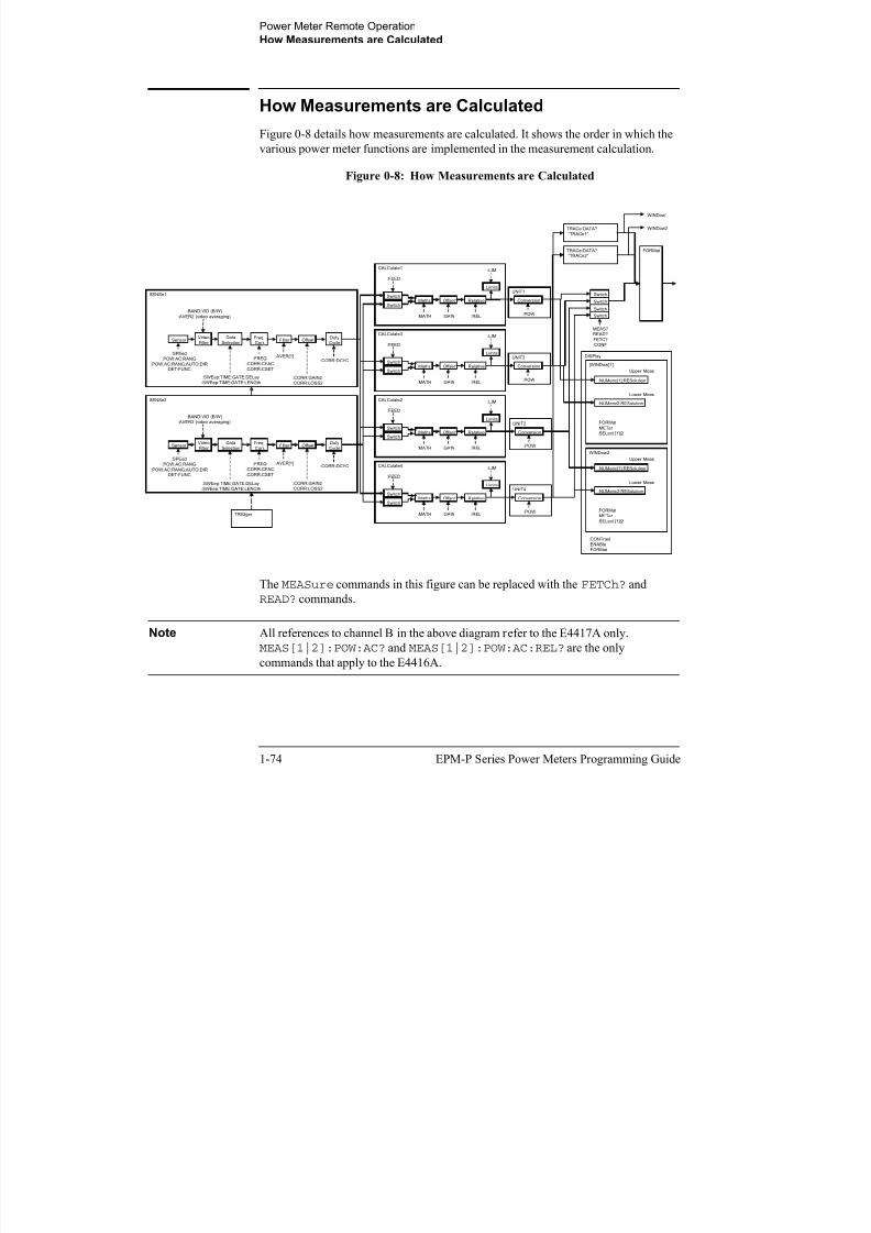
8/9/2019 E4416 Programming Guide
http://slidepdf.com/reader/full/e4416-programming-guide 98/615
1-74 EPM-P Series Power Meters Programming Guide
The MEASure commands in this figure can be replaced with the FETCh? and
READ? commands.
Note All references to channel B in the above diagram refer to the E4417A only. MEAS[1|2]:POW:AC? and MEAS[1|2]:POW:AC:REL? are the only
commands that apply to the E4416A.
TRIGger
DISPlay
WINDow2
:FORMat
:METer
:SELect [1]|2
:NUMeric[1]:RESolution
:NUMeric2:RESolution
Upper Meas
Lower Meas
UNIT4
Conversion
:POW
CALCulate2
Maths Offset Relative
Limits
:MATH :GAIN :REL
:LIM
Switch
Switch
:FEED
UNIT2
Conversion
:POW
UNIT3
Conversion
:POW
UNIT1
Conversion
:POW
CALCulate4
Maths Offset Relative
Limits
:MATH :GAIN :REL
:LIM
Switch
Switch
:FEED
CALCulate1
Maths Offset Relative
Limits
:MATH :GAIN :REL
:LIM
Switch
Switch
:FEED
CALCulate3
Maths Offset Relative
Limits
:MATH :GAIN :REL
:LIM
Switch
Switch
:FEED
[WINDow[1]]
:FORMat
:METer
:SELect [1]|2
:NUMeric[1]:RESolution
:NUMeric2:RESolution
Upper Meas
Lower Meas
SENSe1
Sensor Filter Freq.Corr.
OffsetDutyCycle
:SPEed
:POW:AC:RANG
:POW:AC:RANG:AUTO:DIR:DET:FUNC
:AVER[1]:FREQ
:CORR:CFAC
:CORR:CSET
:CORR:GAIN2
:CORR:LOSS2
:CORR:DCYC
Video
Filter
Data
Selection
:BAND:VID (B/W)
:AVER2 (video averaging)
:SWEep:TIME:GATE:DELay
:SWEep:TIME:GATE:LENGth
SENSe2
Sensor Filter Freq.
Corr.Offset
Duty
Cycle
:SPEed
:POW:AC:RANG
:POW:AC:RANG:AUTO:DIR:DET:FUNC
:AVER[1]:FREQ
:CORR:CFAC
:CORR:CSET
:CORR:GAIN2
:CORR:LOSS2
:CORR:DCYC
Video
Filter
Data
Selection
:BAND:VID (B/W)
:AVER2 (video averaging)
:SWEep:TIME:GATE:DELay
:SWEep:TIME:GATE:LENGth
:CONTrast
:ENABle
:FORMat
FORMat
Switch
Switch
Switch
Switch
MEAS?READ?
FETC?
CONF
TRACe:DATA?
“TRACe1”
TRACe:DATA? “TRACe2”
WINDow1
WINDow2
Power Meter Remote Operation
Status Reporting
Status Reporting
Status reporting is used to monitor the power meter to determine when events have
occurred. Status reporting is accomplished by configuring and reading status
registers.
The power meter has the following main registers:

8/9/2019 E4416 Programming Guide
http://slidepdf.com/reader/full/e4416-programming-guide 99/615
EPM-P Series Power Meters Programming Guide 1-75
• Status Register
• Standard Event Register
• Operation Status Register
• Questionable Status Register
• Device Status Register
A number of other registers exist “behind” these and are described later in thischapter.
Status and Standard Event registers are read using the IEEE-488.2 common
commands.
Operation and Questionable Status registers are read using the SCPI STATus
command subsystem.
Power Meter Remote Operation
Status Reporting
The General Status Register Model
The generalized status register model shown in Figure 0-9 is the building block of the
SCPI status system. This model consists of a condition register, a transition filter, an
event register and an enable register. A set of these registers is called a status group.
Figure 0-9: Generalized Status Register Model
Condition Transition Event Enable

8/9/2019 E4416 Programming Guide
http://slidepdf.com/reader/full/e4416-programming-guide 100/615
1-76 EPM-P Series Power Meters Programming Guide
When a status group is implemented in an instrument, it always contains all of the
component registers. However, there is not always a corresponding command to read
or write to every register.
Condition Register
The condition register continuously monitors the hardware and firmware status of the
power meter. There is no latching or buffering for this register, it is updated in real
time. Condition registers are read-only.
Transition Filter
The transition filter specifies which types of bit state changes in the condition
registers will set corresponding bits in the event register. Transition filter bits may be
set for positive transitions (PTR), negative transitions (NTR), or both. Transition
filters are read-write. They are unaffected by *CLS or queries. After
STATus:PRESet the NTR register is set to 0 and all bits of the PTR are set to 1.
Event Register
The event register latches transition events from the condition register as specified by
the transition filter. Bits in the event register are latched and once set they remain set
until cleared by a query or a *CLS. Once set, an event bit is no longer affected by
condition changes. It remains set until the event register is cleared; either when you
read the register or when you send the *CLS (clear status) command. Event registers
are read-only.
0
1
2
Bit 0
Bit 1
Bit 2
Bit 3
ConditionRegister
TransitionFilter
EventRegister
EnableRegister
L o g i c a l O R
SummaryBit
Power Meter Remote Operation
Status Reporting
Enable Register
The enable register specifies the bits in the event register that can generate a summary
bit. The instrument logically ANDs corresponding bits in the event and enable
registers and ORs all the resulting bits to obtain a summary bit. Enable registers are
read-write. Querying an enable register does not affect it.
An Example Sequence

8/9/2019 E4416 Programming Guide
http://slidepdf.com/reader/full/e4416-programming-guide 101/615
EPM-P Series Power Meters Programming Guide 1-77
Figure 0-10 illustrates the response of a single bit position in a typical status group for
various settings. The changing state of the condition in question is shown at the
bottom of the figure. A small binary table shows the state of the chosen bit in each
status register at the selected times T1 to T5.
Figure 0-10: Typical Status Register Bit Changes
0 0
0 1
11 0
011
0
1
0 0
0
0
0
0
0
1
11
011
0
1 0
0
0
1
1 0
01
0
1
0 0
0 1
0
01
0
1
0 0
0
0
0
0
0 0
0 0 0
0 0 0
1 0
0
0
0
0
Case A
Case B
Case C
Case D
Condition
P T R
N T R
E n a b l e
C o n d i t i o n
E v e n t
S u m m a r y B i t
C o n d i t i o n
E v e n t
S u m m a r y B i t
C o n d i t i o n
E v e n t
S u m m a r y B i t
C o n d i t i o n
E v e n t
S u m m a r y B i t
C o n d i t i o n
E v e n t
S u m m a r y B i t
1
0
T1 T2 T3 T4 T5
0 0
00
00
* * *
* marks when event register is read

8/9/2019 E4416 Programming Guide
http://slidepdf.com/reader/full/e4416-programming-guide 102/615
Power Meter Remote Operation
Status Reporting
The Condition Polling Method
In this polling method, the power meter has a passive role. It only informs the
controller that conditions have changed when the controller asks. When you monitor
a condition with the polling method, you must:
1. Determine which register contains the bit that monitors the condition.2. Send the unique GPIB query that reads that register.
3 E i th bit t if th diti h h d

8/9/2019 E4416 Programming Guide
http://slidepdf.com/reader/full/e4416-programming-guide 103/615
EPM-P Series Power Meters Programming Guide 1-79
3. Examine the bit to see if the condition has changed.
The polling method works well if you do not need to know about the changes the
moment they occur. The SRQ method is more effective if you must know
immediately when a condition changes. Detecting an immediate change in a
condition using the polling method requires your program to continuously read the
registers at very short intervals. This is not particularly efficient and there is a
possibility that an event may be missed.

8/9/2019 E4416 Programming Guide
http://slidepdf.com/reader/full/e4416-programming-guide 104/615
Power Meter Remote Operation
Status Reporting
130 OUTPUT @Pm;”STAT:DEV:NTR 2”140 OUTPUT @Pm;”STAT:DEV:PTR 2”150 OUTPUT @Pm;”*SRE 2”160 !170 ENABLE INTR 7;2 ! Enable an SRQ to cause an interrupt180 LOOP ! Idle loop190 ! Forever200 END LOOP210

8/9/2019 E4416 Programming Guide
http://slidepdf.com/reader/full/e4416-programming-guide 105/615
EPM-P Series Power Meters Programming Guide 1-81
210 !220 ! When a SRQ is detected , the following routine will
service it.230 !240 Srq_i: !250 St=SPOLL(@Pm) ! Serial Poll (reads status byte)260 IF BIT(St,1)=1 THEN ! Device status reg bit set ?
270 OUTPUT @Pm;”STAT:DEV:EVEN?” ! Yes , read register280 ENTER @Pm;Event ! (this also clears it)290 OUTPUT @Pm;”STAT:DEV:COND?”300 ENTER @Pm;Cond310 IF Cond=0 THEN320 PRINT “Sensor disconnected”330 ELSE340 PRINT “Sensor connected”350 END IF360 END IF370 GOTO 170 ! Return to idle loop380 END
Example 2:
10 ! Program to generate an SRQ when an over limit20 ! condition occurs.30 !40 ASSIGN @Pm TO 713 ! Power meter GPIB address
50 ON INTR 7 GOTO Srq_i ! Define service request handler60 CLEAR @Pm ! Selective device clear70 OUTPUT @Pm;”*CLS” ! Clear registers80 OUTPUT @Pm;”SYST:PRES” ! Preset meter90 !100 ! Set upper limit to 2dBm and configure the operation
status110 ! so that an over limit condition will cause an SRQ.120 !
Power Meter Remote Operation
Status Reporting
130 OUTPUT @Pm;”SENS:LIM:UPP 2DBM”140 OUTPUT @Pm;”SENS:LIM:STAT ON”150 OUTPUT @Pm;”STAT:OPER:PTR 4096”160 OUTPUT @Pm;”STAT:OPER:ENAB 4096”170 OUTPUT @Pm;”*SRE 128”180 !190 ENABLE INTR 7;2 ! Enable an SRQ to cause an interrupt200 LOOP ! Idle loop210 ! Fore er

8/9/2019 E4416 Programming Guide
http://slidepdf.com/reader/full/e4416-programming-guide 106/615
1-82 EPM-P Series Power Meters Programming Guide
210 ! Forever220 END LOOP230 !240 ! When a SRQ is detected , the following routine will
service it.250 !260 Srq_i: !
270 St=SPOLL(@Pm) ! Serial Poll (reads status byte)280 IF BIT(St,7)=1 THEN ! Operation status bit set?290 OUTPUT @Pm;”STAT:OPER?”! Yes , read register300 ENTER @Pm;Oper ! (this also clears it)310 OUTPUT @Pm;”STAT:OPER:ULF?”320 ENTER @Pm;Ulf330 IF Ulf=2 THEN PRINT “Over limit detected”340 END IF350 GOTO 190 ! Return to idle loop360 END
Power Meter Remote Operation
Status Reporting
Status Registers
The Status System in the power meter is shown in Figure 0-11. The Operation Status
and Questionable Status groups are 16 bits wide, while the Status Byte and Standard
Event groups are 8 bits wide. In all 16-bit groups, the most significant bit (bit 15) is
not used and is always set to 0.
Figure 0-11: Status System

8/9/2019 E4416 Programming Guide
http://slidepdf.com/reader/full/e4416-programming-guide 107/615
EPM-P Series Power Meters Programming Guide 1-83
Questionable Status
L o g i c a l O R
Condition Event Enable
Operation Status
L o g i c a l O R
Condition Event Enable
Standard Event
L o g i c a l O R
Event Enable*ESR *ESE
Status Byte
L o g i c a l O
R
*STB? *SRE
MAV
0
1
2QUE
ESB
RQS/MSS
OPR
MAV
0
1
2QUE
ESB
XOPR
Output Queue
Device Status
L o g i c a l O R
Condition Event Enable
Error/Event Queue
Power Meter Remote Operation
Status Reporting
The Status Byte Summary Register
The status byte summary register reports conditions from other status registers. Query
data waiting in the power meter’s output buffer is immediately reported through the
“message available” bit (bit 4). Clearing an event register clears the corresponding
bits in the status byte summary register. Reading all messages in the output buffer,
including any pending queries, clears the message available bit.
Table 0-3: Bit Definitions - Status Byte Register

8/9/2019 E4416 Programming Guide
http://slidepdf.com/reader/full/e4416-programming-guide 108/615
1-84 EPM-P Series Power Meters Programming Guide
Bit
Number
Decimal
Weight Definition
0 1 Not Used (Always set to 0)
1 2 Device Status Register summary bit.
One or more bits are set in the Device Status Register (bits
must be “enabled” in enable register)
2 4 Error/Event Queue
3 8 Questionable Status Register summary bit.
One or more bits are set in the Questionable Status Register
(bits must be “enabled” in enable register).
4 16 Data Available
Data is available in the power meter’s output buffer.
5 32 Standard Event
One or more bits are set in the Standard Event register (bits
must be “enabled” in enable register).
6 64 Request Service
The power meter is requesting service (serial poll).
7 128 Operation Status Register summary bit.
One or more bits are set in the Operation Status Register (bits
must be “enabled” in enable register).
Power Meter Remote Operation
Status Reporting
Particular bits in the status byte register are cleared when:
• The standard event, Questionable status, operation status and device status are
queried.
• The error/event queue becomes empty.
• The output queue becomes empty.
The status byte enable register (SRE, service request enable) is cleared when you:
• cycle the instrument power

8/9/2019 E4416 Programming Guide
http://slidepdf.com/reader/full/e4416-programming-guide 109/615
EPM-P Series Power Meters Programming Guide 1-85
cycle the instrument power.
• execute a *SRE 0 command.
Using *STB? to Read the Status Byte
The *STB? (status byte query) command is similar to a serial poll except it is
processed like any other power meter command. The *STB? command returns the
same result as an IEEE-488 serial poll except that the request service bit (bit 6) is not cleared if a serial poll has occurred. The *STB? command is not handled
automatically by the IEEE-488 bus interface hardware and the command will be
executed only after previous commands have completed. Using the *STB? command
does not clear the status byte summary register.
The Standard Event Register
The standard event register reports the following types of instrument events:
power-on detected, command and syntax errors, command execution errors, self-test
or calibration errors, query errors, or when an overlapped command completesfollowing a *OPC command. Any or all of these conditions can be reported in the
standard event summary bit through the enable register. You must write a decimal
value using the *ESE (event status enable) command to set the enable register mask.
Power Meter Remote Operation
Status Reporting
Table 0-4: Bit Definitions - Standard Event Register
Bit
Number
Decimal
Value Definition
0 1 Operation Complete
All overlapped commands following an *OPC commandhave been completed.
1 2 Not Used. (Always set to 0.)

8/9/2019 E4416 Programming Guide
http://slidepdf.com/reader/full/e4416-programming-guide 110/615
1-86 EPM-P Series Power Meters Programming Guide
The standard event register is cleared when you:
• send a *CLS (clear status) command.
• query the event register using the *ESR? (event status register) command.
The standard event enable register is cleared when you:
• cycle the instrument power.
• execute a *ESE 0 command.
2 4 Query Error
A query error occurred, refer to error numbers 410 to 440 in
the User’s Guide.
3 8 Device Error
A device error occurred, refer to error numbers 310 to 350 in
the User’s Guide.
4 16 Execution Error
An execution error occurred, refer to error numbers 211 to
241 in the User’s Guide.
5 32 Command Error
A command syntax error occurred, refer to error numbers 101
to 161 in the User’s Guide.
6 64 User request.
7 128 Power On
Power has been turned off and on since the last time the eventregister was read or cleared.
Power Meter Remote Operation
Status Reporting
Questionable Status Register
The questionable status register provides information about the quality of the power
meter’s measurement results. Any or all of these conditions can be reported in the
questionable data summary bit through the enable register. You must write a value
using the STATus:QUEStionable:ENABle command to set the enable register
mask.
The questionable status model is shown in the pullout at the end of this chapter.

8/9/2019 E4416 Programming Guide
http://slidepdf.com/reader/full/e4416-programming-guide 111/615
EPM-P Series Power Meters Programming Guide 1-87
The following bits in these registers are used by the power meter.
Bit
Number
Decimal
Weight Definition
0 to 2 - Not used
3 8 POWer Summary
4 to 7 - Not used
8 256 CALibration Summary
9 512 Power On Self Test
10 to 14 - Not Used
15 - Not used (always 0)
Power Meter Remote Operation
Status Reporting
The condition bits are set and cleared under the following conditions:
Bit Number Meaning EVENts Causing Bit Changes
3 POWer
Summary
This is a summary bit for the Questionable POWer Register.
• SET:
Error -230, “Data corrupt or stale”
Error -231, “Data questionable;Input Overload”
Error -231, “Data questionable;Input Overload ChA”1
1

8/9/2019 E4416 Programming Guide
http://slidepdf.com/reader/full/e4416-programming-guide 112/615
1-88 EPM-P Series Power Meters Programming Guide
Error -231, “Data questionable;Input Overload ChB”1
Error -231, “Data questionable;PLEASE ZERO”
Error -231, “Data questionable;PLEASE ZERO ChA”1
Error -231, “Data questionable;PLEASE ZERO ChB”1
Error -231, ”Data questionable;Lower window log error”1
Error -231, ”Data questionable;Upper window log error”1
• CLEARED: When no errors are detected by the power meterduring a measurement covering the causes given for it to set.
1. E4417A only
8 CALibration
Summary
This is a summary bit for the Questionable CALibration Register.
• SET:
These may be caused by
CALibration[1|2]:ZERO:AUTO ONCE or
CALibration[1|2]:AUTO ONCE or
CALibration[1|2][:ALL] or
CALibration[1|2][:ALL]?.
Error -231, “Data questionable; ZERO ERROR”
Error -231, “Data questionable; ZERO ERROR ChA”1
Error -231, “Data questionable; ZERO ERROR ChB”1
Error -231, “Data questionable; CAL ERROR”
Error -231, “Data questionable; CAL ERROR ChA”1
Error -231, “Data questionable; CAL ERROR ChB”1
• CLEARED: When any of the commands listed above succeed
and no errors are placed on the error queue.
9 Power On Self
Test
• SET: This bit is set when the power on self test fails.
• CLEARED: When the power on self test passes.
Power Meter Remote Operation
Status Reporting
Operation Status
The Operation Status group monitors conditions in the power meter’s measurement
process.
The Operation status model is shown in the pullout at the end of this chapter.
The following bits in these registers are used by the power meter:
Bit DecimalDefinition

8/9/2019 E4416 Programming Guide
http://slidepdf.com/reader/full/e4416-programming-guide 113/615
EPM-P Series Power Meters Programming Guide 1-89
The condition bits are set and cleared under the following conditions:
Number Weight Definition
0 1 CALibrating Summary
1 - 3 - Not used
4 16 MEASuring Summary
5 32 Waiting for TRIGger Summary
6 - 9 - Not used
10 1024 SENSe Summary
11 2048 Lower Limit Fail Summary
12 4096 Upper Limit Fail Summary
13 to 14 - Not used
15 - Not used (always 0)
Bit
Number Meaning EVENts Causing Bit Changes
0 CALibrating This is a summary bit for the Operation CALibrating
Register.
• SET: At beginning of zeroing
(CALibration:ZERO:AUTO ONCE) and at the
beginning of calibration (CALibration:AUTOONCE). Also for the compound command/query
CALibration[:ALL]?, this bit is set at the
beginning of the zero.
• CLEARED: At the end of zeroing or calibration.
Power Meter Remote Operation
Status Reporting
4 MEASuring This is a summary bit for the Operation MEASuring
Register.
• SET: When the power meter is taking a measurement.• CLEARED: When the measurement is finished.
5 Waiting for This is a summary bit for the Operation TRIGger Register.
Bit
Number Meaning EVENts Causing Bit Changes

8/9/2019 E4416 Programming Guide
http://slidepdf.com/reader/full/e4416-programming-guide 114/615
1-90 EPM-P Series Power Meters Programming Guide
TRIGger • SET: When the power meter enters the “wait for trigger”
state.
• CLEARED: When the power meter enters the “idle”
state.
10 SENSe This is a summary bit for the Operation SENSe Register.
• SET: When the power meter is reading data from theE-Series power sensor EEPROM.
• CLEARED: When the power meter is not reading data
from the E-Series power sensor or N8480 Series power
sensor EEPROM.
11 Lower Limit
Fail
This is a summary bit for the Lower Limit Fail Register.
• SET: If a measurement is made and either a channel or
window lower limit test fails.
• CLEARED: If a measurement is made and the lower
limit test is not enabled or the test is enabled and passes.
12 Upper Limit
Fail
This is a summary bit for the Upper Limit Fail Register.
• SET: If a measurement is made and either a channel or
window upper limit test fails.
• CLEARED: If a measurement is made and the upper
limit test is not enabled or the test is enabled and passes.
Power Meter Remote Operation
Status Reporting
Device Status Register
The device status register set contains bits which give device dependent information.
The following bits in these registers are used by the power meter:
BitNumber
DecimalWeight
Definition
0 - Not used

8/9/2019 E4416 Programming Guide
http://slidepdf.com/reader/full/e4416-programming-guide 115/615
EPM-P Series Power Meters Programming Guide 1-91
1 2 Channel A sensor connected
2 4 Channel B sensor connected1
1. E4417A only
3 8 Channel A sensor error
4 16 Channel B sensor error 1
5 32 Channel A sensor Front/Rear
6 64 Channel B sensor Front/Rear 1
14 16384 Front Panel key press
Power Meter Remote Operation
Status Reporting
The condition bits are set and cleared under the following conditions:
Bit
Number Meaning EVENts Causing Bit Changes
1 Channel A
sensor
connected
• SET: When a power sensor is connected to the Channel A
input.
• CLEARED: When no power sensor is connected to the
Channel A input.

8/9/2019 E4416 Programming Guide
http://slidepdf.com/reader/full/e4416-programming-guide 116/615
1-92 EPM-P Series Power Meters Programming Guide
2 Channel B
sensor
connected
• SET: When a power sensor is connected to the Channel B
input.
• CLEARED: When no power sensor is connected to the
Channel B input.
3 Channel A
error
• SET: If the power sensor EEPROM on Channel A has
failed or if there are power sensors connected to both therear and front panel Channel A connectors.
• CLEARED: In every other condition.
4 Channel B
error
• SET: If the power sensor EEPROM on Channel B has
failed or if there are power sensors connected to both the
rear and front panel Channel B connectors.
• CLEARED: In every other condition.
5 Channel A
Front/Rear
• SET: If a power sensor is connected to the Channel A
rear panel.• CLEARED: If a power sensor is connected to the
Channel A front panel.
6 Channel B
Front/Rear
• SET: If a power sensor is connected to the Channel B rear
panel.
• CLEARED: If a power sensor is connected to the
Channel B front panel.
14 Front Panel
Key Press
This is an event, and DOES NOT set the condition register.
The bit will be set in the event register which will be clearedwhen read. Note that the transition registers are of no use for
this bit.
Power Meter Remote Operation
Status Reporting
Using the Operation Complete Commands
The *OPC? and *OPC commands allow you to maintain synchronization between the
computer and the power meter. The *OPC? query command places an ASCII
character 1 into the power meter’s output queue when all pending power meter
commands are complete. If your program reads this response before continuing
program execution, you can ensure synchronization between one or more instrumentsand the computer.
The *OPC command sets bit 0 (Operation Complete) in the Standard Event Status
Register hen all pending po er meter operations are complete B enabling this bit

8/9/2019 E4416 Programming Guide
http://slidepdf.com/reader/full/e4416-programming-guide 117/615
EPM-P Series Power Meters Programming Guide 1-93
Register when all pending power meter operations are complete. By enabling this bit
to be reflected in the Status Register, you can ensure synchronization using the GPIB
serial poll.
Procedure
• Send a device clear message to clear the power meter’s output buffer.
• Clear the event registers with the *CLS (clear status) command.
• Enable operation complete using the *ESE 1 command (standard event register).
• Send the *OPC? (operation complete query) command and enter the result to
assure synchronization.
• Send your programming command string, and place the *OPC (operation
complete) command as the last command.
• Use a serial poll to check to see when bit 5 (standard event) is set in the status byte
summary register. You could also configure the power meter for an SRQ interrupt
by sending *SRE 32 (status byte enable register, bit 5).
Power Meter Remote Operation
Status Reporting
Examples
This example program uses the *OPC? command to determine when the power meter
has finished calibrating.
CAL:AUTO ONCE*OPC?
MEAS:POW:AC?
This example program, in HP Basic, uses the *OPC command and serial poll to
determine when the power meter has finished calibrating. The advantage to using this
h d h d i h h f h i

8/9/2019 E4416 Programming Guide
http://slidepdf.com/reader/full/e4416-programming-guide 118/615
1-94 EPM-P Series Power Meters Programming Guide
method over the *OPC? command is that the computer can perform other operations
while it is waiting for the power meter to finish calibrating.
10 ASSIGN @Power TO 71320 OUTPUT @Power;“*CLS”30 OUTPUT @Power;“*ESE 1”
40 OUTPUT @Power;“CAL:AUTO ONCE;*OPC”50 WHILE NOT BIT(SPOLL(@Power),5)60 !(Computer carries out other operations here)70 END WHILE80 OUTPUT @Power;“MEAS:POW:AC?”90 ENTER @Power;Result100 PRINT Result110 END
Power Meter Remote Operation
Saving and Recalling Power Meter Configurations
Saving and Recalling Power Meter Configurations
To reduce repeated programming, up to ten power meter configurations can be stored
in the power meter’s non-volatile memory. The error list, GPIB address,
programming language, sensor calibration table data, zeroing and calibration
information are not stored.
How to Save and Recall a Configuration

8/9/2019 E4416 Programming Guide
http://slidepdf.com/reader/full/e4416-programming-guide 119/615
EPM-P Series Power Meters Programming Guide 1-95
Power meter configurations are saved and recalled with the following commands:
*SAV <NRf>*RCL <NRf>
The range of values for <NRf> in the above commands is 1 to 10.
Example Program
10 ASSIGN @POWER TO 71320 !Configure the power meter30 OUTPUT @POWER;“UNIT:POW W”40 OUTPUT @POWER;“SENS:CORR:LOSS2 -10”50 OUTPUT @POWER;“SENS:CORR:LOSS2:STAT ON”60 !Save the configuration
70 OUTPUT @POWER;“*SAV 5”80 PRINT “Configuration Saved”90 !Now reset the power meter100 OUTPUT @POWER;“*RST”110 !Recall the configuration120 OUTPUT @POWER;”*RCL 5”130 PRINT “Configuration Recalled”140 PRINT “Save and Recall complete”150 END
Power Meter Remote Operation
Using Device Clear to Halt Measurements
Using Device Clear to Halt Measurements
Device clear is an IEEE-488 low-level bus message which can be used to halt
measurements in progress. Different programming languages and IEEE-488 interface
cards provide access to this capability through their own unique commands. The
status registers, the error queue, and all configuration states are left unchanged when adevice clear message is received. Device clear performs the following actions.
• All measurements in progress are aborted.
• The power meter returns to the trigger “idle state”.

8/9/2019 E4416 Programming Guide
http://slidepdf.com/reader/full/e4416-programming-guide 120/615
1-96 EPM-P Series Power Meters Programming Guide
p gg
• The power meter’s input and output buffers are cleared.
• The power meter is prepared to accept a new command string.
Power Meter Remote Operation
An Introduction to the SCPI Language
An Introduction to the SCPI Language
Standard Commands for Programmable Instruments (SCPI) defines how you
communicate with an instrument from a bus controller. The SCPI language uses a
hierarchical structure similar to the file systems used by many bus controllers. The
command tree is organized with root-level commands (also called subsystems) positioned at the top, with multiple levels below each root-level command. You must
specify the complete path to execute the individual lower-level commands.

8/9/2019 E4416 Programming Guide
http://slidepdf.com/reader/full/e4416-programming-guide 121/615
EPM-P Series Power Meters Programming Guide 1-97
Mnemonic Forms
Each keyword has both a long and a short form. A standard notation is used to
differentiate the short form keyword from the long form keyword. The long form of
the keyword is shown, with the short form portion shown in uppercase characters, and
the rest of the keyword shown in lowercase characters. For example, the short form of
TRIGger is TRIG.
Using a Colon (:)
When a colon is the first character of a command keyword, it indicates that the next
command mnemonic is a root-level command. When a colon is inserted between two
command mnemonics, the colon moves the path down one level in the present path
(for the specified root-level command) of the command tree. You must separate
command mnemonics from each other using a colon. You can omit the leading colon
if the command is the first of a new program line.
“B” Subsystem
:G :I:H
:M :N=:B:H:N
“A” Subsystem
:D :F:E
“C” Subsystem
:J :L=:C:L:K
Power Meter Remote Operation
An Introduction to the SCPI Language
Using a Semicolon (;)
Use a semicolon to separate two commands within the same command string. The
semicolon does not change the present path specified. For example, the following two
statements are equivalent. Note that in the first statement the first colon is optional but
the third is compulsory.
:DISP:FORM DIG;:DISP:RES 2:DISP:FORM DIG;RES 2
Using a Comma (,)

8/9/2019 E4416 Programming Guide
http://slidepdf.com/reader/full/e4416-programming-guide 122/615
1-98 EPM-P Series Power Meters Programming Guide
If a command requires more than one parameter, you must separate adjacent
parameters using a comma.
Using Whitespace
You must use whitespace characters, [tab], or [space] to separate a parameter from acommand keyword. Whitespace characters are generally ignored only in parameter
lists.
Using “?” Commands
The bus controller may send commands at any time, but a SCPI instrument may only
send responses when specifically instructed to do so. Only query commands
(commands that end with a “?”) will instruct the instrument to send a response
message. Queries return either measured values or internal instrument settings.
Note If you send two query commands without reading the response from the first,
then attempt to read the second response, you may receive some data from the
first response followed by the complete second response. To avoid this, do not
send a query command without reading the response. When you cannot avoid
this situation, send a device clear before sending the second query command.
Using “*” Commands
Commands starting with a “*” are called common commands. They are required to
perform the identical function for all instruments that are compliant with the
IEEE-488.2 interface standard. The “*” commands are used to control reset, self-test,
and status operations in the power meter.
Power Meter Remote Operation
An Introduction to the SCPI Language
Syntax Conventions
Throughout this guide, the following conventions are used for SCPI command syntax.
• Square brackets ([]) indicate optional keywords or parameters.
• Braces ({}) enclose one or more parameters that may be included zero or more
times.
• Triangle brackets (<>) indicate that you must substitute a value for the enclosed
parameter.
• Bars (|) can be read as “or” and are used to separate alternative parameter options.

8/9/2019 E4416 Programming Guide
http://slidepdf.com/reader/full/e4416-programming-guide 123/615
EPM-P Series Power Meters Programming Guide 1-99
Syntax Diagram Conventions
• Solid lines represent the recommended path.
• Ovals enclose command mnemonics. The command mnemonic must be entered
exactly as shown.
• Dotted lines indicate an optional path for bypassing secondary keywords.
• Arrows and curved intersections indicate command path direction.
SCPI Data Types
The SCPI language defines different data formats for use in program messages and
response messages. Instruments are flexible listeners and can accept commands and
parameters in various formats. However, SCPI instruments are precise talkers. This
means that SCPI instruments always respond to a particular query in a predefined,rigid format.
<boolean> Definition
Throughout this chapter <boolean> is used to represent ON|OFF|<NRf>. boolean
parameters have a value of 0 or 1 and are unitless. ON corresponds to 1 and OFF
corresponds to 0.
On input, an <NRf> is rounded to an integer. A nonzero result is interpreted as 1.
Queries always return a 1 or 0, never ON or OFF.
Power Meter Remote Operation
An Introduction to the SCPI Language
<character_data> Definition
Throughout this chapter <character_data> is used to represent character data,
that is, A - Z, a - z, 0 - 9 and _ (underscore). For example: START and R6_5F. The
format is defined as:
<upper-casealpha>
<upper-casealpha>

8/9/2019 E4416 Programming Guide
http://slidepdf.com/reader/full/e4416-programming-guide 124/615
1-100 EPM-P Series Power Meters Programming Guide
<NAN> Definition
Not a number (NAN) is represented as 9.91 E37. Not a number is defined in IEEE 754.
<digit>
Power Meter Remote Operation
An Introduction to the SCPI Language
<non-decimal numeric> Definition
Throughout this chapter <non-decimal numeric> is used to represent numeric
information in bases other than ten (that is, hexadecimal, octal and binary). The
following syntax diagram shows the standard for these three data structures. For
example, #HA2F, #ha4e, #Q62, #q15, #B01011.
A/a
B/b

8/9/2019 E4416 Programming Guide
http://slidepdf.com/reader/full/e4416-programming-guide 125/615
EPM-P Series Power Meters Programming Guide 1-101
Refer to section 7.7.4.1 of IEEE 488.2 for further details.
C/c
D/d
E/e
F/f
<digit>
H/h
1
2
3
4
5
6
0
7
Q/q
0
1
#
B/b
Power Meter Remote Operation
An Introduction to the SCPI Language
<NRf> Definition
Throughout this chapter <NRf> is used to denote a flexible numeric representation.
For example: +200; -56; +9.9E36. Refer to section 7.7.2.1 of IEEE 488.2 for further
details.
<NR1> Definition
Throughout this chapter <NR1> numeric response data is defined as:
digit
+

8/9/2019 E4416 Programming Guide
http://slidepdf.com/reader/full/e4416-programming-guide 126/615
1-102 EPM-P Series Power Meters Programming Guide
For example:
• 146
• +146
• -12345
Refer to section 8.7.2 of IEEE 488.2 for further details.
<NR2> Definition
Throughout this chapter <NR2> numeric response data is defined as:
For example:
• 12.3
• +1.2345• -0.123
Refer to section 8.7.3 of IEEE 488.2 for further details.
digit
+
digit
Power Meter Remote Operation
An Introduction to the SCPI Language
<NR3> Definition
Throughout this chapter <NR3> numeric response data is defined as:
digit
+
digit
digit
+
E

8/9/2019 E4416 Programming Guide
http://slidepdf.com/reader/full/e4416-programming-guide 127/615
EPM-P Series Power Meters Programming Guide 1-103
For example:
• 1.23E+6
• 123.4E-54
• -1234.567E+90.
Refer to section 8.7.4 of IEEE 488.2 for further details.
<numeric_value> Definition
Throughout this chapter the decimal numeric element is abbreviated to
<numeric_value>. For example, <NRf>, MINimum , MAXimum , DEFault or
Not A Number (NAN).
Power Meter Remote Operation
An Introduction to the SCPI Language
<string> Definition
Throughout this chapter <string> is used to represent 7-bit ASCII characters.
The format is defined as:
<inserted '>
<non-singlequote char>
'
'
'
Program Data

8/9/2019 E4416 Programming Guide
http://slidepdf.com/reader/full/e4416-programming-guide 128/615
1-104 EPM-P Series Power Meters Programming Guide
<inserted ">
<non-double quote char>
""
"
<inserted ">
<non-double quote char>
"
"
"
quote char>
Response Data
Power Meter Remote Operation
An Introduction to the SCPI Language
Input Message Terminators
Program messages sent to a SCPI instrument must terminate with a <newline>
character. The IEEE.488 EOI (end or identify) signal is interpreted as a <newline>
character and may also be used to terminate a message in place of the <newline>
character. A <carriage return> followed by a <newline> is also accepted. Many
programming languages allow you to specify a message terminator character or EOIstate to be automatically sent with each bus transaction. Message termination always
sets the current path back to the root-level.

8/9/2019 E4416 Programming Guide
http://slidepdf.com/reader/full/e4416-programming-guide 129/615
EPM-P Series Power Meters Programming Guide 1-105
Power Meter Remote Operation
Summary Of Commands
Summary Of Commands
Note This Guide details the commands available for both the E4416A and the E4417A
power meters. As the E4416A is a single channel power meter only channel A
can be selected. Where instances of channel selection are detailed in this chapter
they are only relevant for the E4417A.
This section summarizes the SCPI (Standard Commands for Programmable
Instruments) commands available to program the power meter. All the commands
listed also have queries unless otherwise stated in the “Notes” column. Refer to later

8/9/2019 E4416 Programming Guide
http://slidepdf.com/reader/full/e4416-programming-guide 130/615
1-106 EPM-P Series Power Meters Programming Guide
q
chapters for more details on each command.
In different subsystems the numeric suffix of program mnemonics can represent
either a channel selection or a window selection. Refer to the appropriate command
description to verify the meaning of the numeric suffix.
With commands that require you to specify a channel, Channel A is represented by a
1 and Channel B by a 2. If you omit the channel number, Channel A is assumed.
With commands that require you to specify a window, the upper window is
represented by a 1 and the lower window by a 2. If you omit the window number, the
upper window is assumed.
Power Meter Remote Operation
Summary Of Commands
MEASurement Commands
Keyword Parameter Form Notes
CONFigure[1]|2|3|4 [query only]
CONFigure[1]|2|3|4[:SCALar]
[:POWer:AC] [<expected_value>
[,<resolution>[,<source list>]]]
[no query]
:RELative [<expected_value> [,<resolution>[,<source list>]]]
[no query]
[non-SCPI]
:DIFFerence [<expected_value> [,<resolution>[,<source list>]]]
[no query]
[non-SCPI]
:RELative [<expected_value> [,<resolution>[,<source list>]]]
[no query]
[non-SCPI]

8/9/2019 E4416 Programming Guide
http://slidepdf.com/reader/full/e4416-programming-guide 131/615
EPM-P Series Power Meters Programming Guide 1-107
[, resolution [, source list ]]] [non SCPI]
:RATio [<expected_value> [,<resolution>[,<source list>]]]
[no query]
:RELative [<expected_value> [,<resolution>[,<source list>]]]
[no query]
[non-SCPI]
FETCh[1]|2|3|4[:SCALar]
[:POWer:AC]? [<expected_value> [,<resolution>[,<source list>]]]
[query only]
:RELative? [<expected_value> [,<resolution>[,<source list>]]]
[query only]
[non-SCPI]
:DIFFerence? [<expected_value> [,<resolution>[,<source list>]]]
[query only]
[non-SCPI]
:RELative? [<expected_value> [,<resolution>[,<source list>]]]
[query only]
[non-SCPI]
:RATio? [<expected_value>
[,<resolution>[,<source list>]]]
[query only]
:RELative? [<expected_value> [,<resolution>[,<source list>]]]
[query only]
[non-SCPI]
READ[1]|2|3|4[:SCALar]
[:POWer:AC]? [<expected_value> [,<resolution>[,<source list>]]]
[query only]
:RELative? [<expected_value> [,<resolution>[,<source list>]]]
[query only]
[non-SCPI]
:DIFFerence? [<expected_value> [,<resolution>[,<source list>]]]
[query only]
[non-SCPI]
:RELative? [<expected_value> [,<resolution>[,<source list>]]]
[query only][non-SCPI]
:RATio? [<expected_value> [,<resolution>[,<source list>]]]
[query only]
:RELative? [<expected_value> [,<resolution>[,<source list>]]]
[query only]
[non-SCPI]
Power Meter Remote Operation
Summary Of Commands
MEASure[1]|2|3|4[:SCALar]
[:POWer:AC]? [<expected_value> [,<resolution>[,<source list>]]]
[query only]
:RELative? [<expected_value> [,<resolution>[,<source list>]]]
[query only]
[non-SCPI]
:DIFFerence? [<expected_value> [,<resolution>[,<source list>]]]
[query only][non-SCPI]
:RELative? [<expected_value> [,<resolution>[,<source list>]]]
[query only]
[non-SCPI]
:RATio? [<expected_value> [ <resolution>[ <source list>]]]
[query only]
Keyword Parameter Form Notes

8/9/2019 E4416 Programming Guide
http://slidepdf.com/reader/full/e4416-programming-guide 132/615
1-108 EPM-P Series Power Meters Programming Guide
CALCulate Subsystem
[,<resolution>[,<source list>]]]:RELative? [<expected_value>
[,<resolution>[,<source list>]]][query only]
[non-SCPI]
Keyword Parameter Form Notes
CALCulate[1]|2|3|4:FEED[1]|2 <data_handle>:GAIN
[:MAGNitude] <numeric_value>:STATe <boolean>
:LIMit:CLEar:AUTO <boolean>
[:IMMediate]:FAIL? [query only]
:FCOunt? [query only]
:LOWer[:DATA] <numeric_value>
:STATe <boolean>:UPPer[:DATA] <numeric_value>
:MATH[:EXPRession] <string>:CATalog? [query only]
:PHOLd:CLEAr
:RELative [no query]
[:MAGNitude]:AUTO <boolean>
:STATe <boolean>
Power Meter Remote Operation
Summary Of Commands
CALibration Subsystem
Keyword Parameter Form Notes
CALibration[1]|2[:ALL] [event;
no query]
[:ALL]? [event;
query]:AUTO <boolean>|ONCE:ECONtrol
:STATe <boolean>:RCALibration <boolean>:RCFactor <numeric_value> [non-SCPI]
:ZERO

8/9/2019 E4416 Programming Guide
http://slidepdf.com/reader/full/e4416-programming-guide 133/615
EPM-P Series Power Meters Programming Guide 1-109
DISPlay Subsystem
FORMat Subsystem
:AUTO <boolean>|ONCE:NORMal:AUTO <boolean>|ONCE
Keyword Parameter Form Notes
DISPlay:CONTrast <numeric_value>:ENABle <boolean>:SCReen
:FORMat <character_data>[:WINDow[1]|2]
:ANALog
:LOWer <numeric_value>:UPPer <numeric_value>:FORMat <character_data> [non-SCPI]
:METer:LOWer <numeric_value> [non-SCPI]
:UPPer <numeric_value> [non-SCPI]
[:NUMeric[1]|2]:RESolution <numeric_value>
:SELect[1]|2[:STATe] <boolean>:TRACe:FEED <character_data>:LOWer <numeric_value>:UPPer <numeric_value>
Keyword Parameter Form Notes
FORMat[:READings]

8/9/2019 E4416 Programming Guide
http://slidepdf.com/reader/full/e4416-programming-guide 134/615
Power Meter Remote Operation
Summary Of Commands
MEMory Subsystem
Keyword Parameter Form Notes
MEMory:CATalog
[:ALL]? [query only]
:STATe? [query only]
:TABLe? [query only]:CLEar
[:NAME] <character_data> [no query],
[non-SCPI]}
:TABLe [no query]
:FREE[:ALL]? [query only]
STAT ? [q er onl ]

8/9/2019 E4416 Programming Guide
http://slidepdf.com/reader/full/e4416-programming-guide 135/615
EPM-P Series Power Meters Programming Guide 1-111
OUTPut Subsystem
:STATe? [query only]
:TABLe? [query only]
:NSTates? [query only]
:STATe:CATalog? [query only]
:DEFine <character_data> [,<numeric_value>]
[non-SCPI]
:TABLe:FREQuency <numeric_value>
[,<numeric_value>]:POINts? [query only]
:GAIN[:MAGNitude] <numeric_value>
[,<numeric_value>][non-SCPI]
:POINts? [query only],
[non-SCPI]
:MOVE <character_data>, <character_data>
[no query], [non-SCPI]
:SELect <character_data> [no query],
[non-SCPI]
Keyword Parameter Form Notes
OUTPut:RECorder[1]|2
:FEED <data_handle>:LIMit:LOWer <numeric_value>:UPPer <numeric_value>
:STATe <boolean>:ROSCillator
[:STATe] <boolean>:TRIGger
[:STATe] <boolean>:TTL[1]|2
Power Meter Remote Operation
Summary Of Commands
:ACTive HIGH|LOW:FEED <string>:STATe <boolean>
Keyword Parameter Form Notes

8/9/2019 E4416 Programming Guide
http://slidepdf.com/reader/full/e4416-programming-guide 136/615
1-112 EPM-P Series Power Meters Programming Guide
Power Meter Remote Operation
Summary Of Commands
[SENSe] Subsystem
Keyword Parameter Form Notes
[SENSe[1]]|SENSe2:AVERage
:COUNt <numeric_value>:AUTO <boolean>
:SDETect <boolean> [non-SCPI][:STATe] <boolean>AVERage2
:COUNt <numeric_value>[:STATe] <boolean>
:BANDwidth|BWIDth:VIDeo <character_data>
:CORRection

8/9/2019 E4416 Programming Guide
http://slidepdf.com/reader/full/e4416-programming-guide 137/615
EPM-P Series Power Meters Programming Guide 1-113
:CORRection:CFACtor|GAIN[1] [non-SCPI]
[:INPut][:MAGNitude] <numeric_value>
:CSET[1]|CSET2
[:SELect] <string>:STATe <boolean>
:DCYCle|GAIN3 [non-SCPI]
[:INPut][:MAGNitude] <numeric_value>
:STATe <boolean>:FDOFfset|GAIN4[:INPut]
[:MAGNitude]? [query only]
:GAIN2:STATe <boolean>
[:INPut][:MAGNitude] <numeric_value>
:DETector:FUNCtion <character_data>
:FREQuency[:CW|:FIXed] <numeric_value>
:MRATe <character_data>:POWer
:AC:RANGe <numeric_value> [non-SCPI]
:AUTO <boolean>:SPEed <numeric_value> [non-SCPI]
:SWEep[1]|2|3|4:OFFSet:TIME <numeric_value>
:TIME <numeric_value>:TRACe
:LIMit:LOWer <numeric_value>:UPPer <numeric_value>
:OFFSet
Power Meter Remote Operation
Summary Of Commands
:TIME <numeric_value>:TIME <numeric_value>:UNIT <character_data>
:V2P ATYPe|DTYPe [non-SCPI]
Keyword Parameter Form Notes

8/9/2019 E4416 Programming Guide
http://slidepdf.com/reader/full/e4416-programming-guide 138/615
1-114 EPM-P Series Power Meters Programming Guide
Power Meter Remote Operation
Summary Of Commands
STATus Subsystem
As the status reporting commands are orthogonal, the same commands apply to all the
registers. The registers are:
STATus:DEViceSTATus:OPERation
STATus:OPERation:CALibrating[:SUMMary]STATus:OPERation:LLFail[:SUMMary]STATus:OPERation:MEAsuring[:SUMMary]STATus:OPERation:SENSe[:SUMMary]STATus:OPERation:TRIGger[:SUMMary]STATus:OPERation:ULFail[:SUMMary]STATus:QUEStionable

8/9/2019 E4416 Programming Guide
http://slidepdf.com/reader/full/e4416-programming-guide 139/615
EPM-P Series Power Meters Programming Guide 1-115
STATus:QUEStionableSTATus:QUEStionable:CALibration[:SUMMary]STATus:QUEStionable:POWer[:SUMMary]
The following five commands operate on each of these registers. However, to avoidduplication they are only listed once.
Keyword Parameter Form Notes
:CONDition? [query only]
:ENABle <NRf>|<non-decimal numeric>[:EVENt?] [query only]
:NTRansition <NRf>|<non-decimal numeric>:PTRansition <NRf>|<non-decimal numeric>
Power Meter Remote Operation
Summary Of Commands
SYSTem Subsystem
Keyword Parameter Form Notes
SYSTem :COMMunicate
:GPIB[:SELF]
:ADDRess <numeric_value>:SERial:CONTrol
:DTR <boolean>:RTS <boolean>
[:RECeive]:BAUD <numeric_value>:BITs <numeric_value>
|

8/9/2019 E4416 Programming Guide
http://slidepdf.com/reader/full/e4416-programming-guide 140/615
1-116 EPM-P Series Power Meters Programming Guide
TRACe Subsystem
:PACE XON|NONE:PARity
[:TYPE] EVEN|ODD|ZERO|ONE|NONE:SBITs <numeric_value>
:TRANsmit:AUTO? [query only]
:BAUD <numeric_value>:BITs <numeric_value>:ECHO <boolean>:PACE XON|NONE:PARity
[:TYPE] EVEN|ODD|ZERO|ONE|NONE:SBITs <numeric_value>
:HELP:HEADers? [query only]
:LoCAL:PRESet [event; no
query]
:REMote:RINTerface GPIB|RS232|RS422:RWLock:VERSion? [query only]
Keyword Parameter Form NotesTRACe[1]|2
[:DATA]? <character_data> [query only]
:STATe <boolean>:UNIT <character_data>
Power Meter Remote Operation
Summary Of Commands
TRIGger Subsystem
Keyword Parameter Form Notes
ABORt[1]|2 [no query]
[non-SCPI]
INITiate[1]|2:CONTinuous <boolean>[:IMMediate] [no query]
INITiate:CONTinuous
:ALL <boolean>:SEQuence[1]|2 <boolean>
[:IMMediate]:ALL [no query]
:SEQuence[1]|2 [no query]
TRIG [1]|2

8/9/2019 E4416 Programming Guide
http://slidepdf.com/reader/full/e4416-programming-guide 141/615
EPM-P Series Power Meters Programming Guide 1-117
UNIT Subsystem
TRIGger[1]|2:DELay
:AUTO <boolean>[:IMMediate] [no query]
:SOURce BUS|EXTernal|HOLD|IMMediate|INTernal[[1]|2]
TRIGger[:SEQuence]
:DELay <numeric_value>:HOLDoff <numeric_value>:HYSTeresis <numeric_value>:LEVel <numeric_value>:AUTO <boolean>
:SLOPe <character_data>[:SEQuence[1]|2]
:COUNt <numeric_value>:DELay:AUTO <boolean>
:IMMediate [no query]
:SOURce BUS|EXTernal|HOLD|IMMediate|INTernal[[1]|2]
Keyword Parameter Form Notes
UNIT[1]|2|3|4:POWer <amplitude unit>
:RATio <ratio_unit> [non-SCPI]
Power Meter Remote Operation
Summary Of Commands
SERVice Subsystem
Keyword Parameter Form Notes
SERVice:BIST
:CALibrator <boolean>:FPATH[1]|2
:MEASure? [query only]
:REFerence <numeric_value> [no query]
:STATe <boolean> [no query]
:TBASe:STATe <boolean>
:TRIG:LEVel
:STATe? [query only]
:TEST? [query only]

8/9/2019 E4416 Programming Guide
http://slidepdf.com/reader/full/e4416-programming-guide 142/615
1-118 EPM-P Series Power Meters Programming Guide
:TEST? [query only]
:OPTion <character_data>:SENSor[1]|2
:CALFactor <cal_factor_data>
:CDATe? [query only]:CORRections
:STATe <boolean>:CPLace? [query only]
:FREQuency:MAXimum? [query only]
:MINimum? [query only]
:PCALfactor <cal_factor_data>:POWer
:AVERage:MAXimum? [query only]
:PEAK:MAXimum? [query only]
:USABle:MAXimum? [query only]
:MINimum? [query only]
:RADC? [query only]
:SNUMber? [query only]
:TNUMber? [query only]
:TYPE? [query only]
:SNUMber <character_data>:VERSion
:PROCessor <character_data>:SYSTem <character_data>
Power Meter Remote Operation
SCPI Compliance Information
SCPI Compliance Information
The power meter complies with the rules and regulations of the present version of
SCPI (Standard Commands for Programmable Instruments). You can determine the
SCPI version with which the power meter’s is in compliance by sending the
SYSTem:VERSion? command from the remote interface.
The following commands are device-specific to the HP EPM-441A/442A. They are
not included in the 1996.0 version of the SCPI standard. However, these commands
are designed with the SCPI format in mind and they follow all of the syntax rules of
the standard.
CALibration[1|2]:ECONtrol:STATeCALibration[1|2]:RCALibration

8/9/2019 E4416 Programming Guide
http://slidepdf.com/reader/full/e4416-programming-guide 143/615
EPM-P Series Power Meters Programming Guide 1-119
CALibration[1|2]:RCALibrationCALibration[1|2]:RCFactorDISPlay[:WINDow[1|2]]:FORMat
DISPlay[:WINDow[1|2]]:METer:LOWerDISPlay[:WINDow[1|2]]:METer:UPPerDISPlay[:WINDow[1|2]]:RESolutionDISPlay[:WINDow[1|2]]:SELectMEMory:CLEar[:NAME]MEMory:TABLe:SELectMEMory:STATe:DEFineMEMory:TABLe:GAIN[:MAGNitude]MEMory:TABLe:GAIN:POINts?MEMory:TABLe:MOVEOUTPut:TTL[1|2]:ACTiveOUTPut:TTL[1|2]:FEEDOUTPut:TTL[1|2]:STATe[SENSe[1]]|SENSe2:AVERage:SDETect[SENSe[1]]|SENSe2:CORRection:CFACtor[SENSe[1]]|SENSe2:CORRection:DCYCle[SENSe[1]]|SENSe2:CORRection:FDOFfset[SENSe[1]]|SENSe2:SPEed[SENSe[1]]|SENSe2:POWer:AC:RANGe
SERVice:SENSor[1|2]:CDATE?SERVice:SENSor[1|2]:CPLace?SERVice:SENSor[1|2]:SNUMber?SERVice:SENSor[1|2]:TYPE?SYSTem:LOCalSYSTem:REMoteSYSTem:RINTerfaceSYSTem:RWLock

8/9/2019 E4416 Programming Guide
http://slidepdf.com/reader/full/e4416-programming-guide 144/615
2

8/9/2019 E4416 Programming Guide
http://slidepdf.com/reader/full/e4416-programming-guide 145/615
Measurement Commands
Measurement Commands
Measurement Commands
Measurement Commands
Measurement commands are high level commands used to acquire data. They enable
you to trade interchangeability against fine control of the measurement process.
Measurement
CommandDescription
MEASure? Provides the simplest way to program a power meter for measurements.
MEASure? is a compound command which is equivalent to an ABORT
followed by a CONFigure and a READ?. It does not enable much
flexibility or control over measurement settings.
CONFigure Used to change the power meter’s configuration values. CONFigure
must then be followed by another command which takes the

8/9/2019 E4416 Programming Guide
http://slidepdf.com/reader/full/e4416-programming-guide 146/615
2-2 EPM-P Series Power Meters Programming Guide
The CONFigure, FETCh?, READ? and MEASure? commands all have a numeric
suffix which refers to a specific window/measurement. For example:
• CONFigure1? : Returns the configuration of the upper window/upper
measurement.
• CONFigure2? : Returns the configuration of the lower window/upper
measurement.
• CONFigure3? : Returns the configuration of the upper window/lower
measurement.
• CONFigure4? : Returns the configuration of the lower window/lower
measurement.
must then be followed by another command which takes the
measurement—for example, a READ? followed by a FETCh?.
READ? Takes a measurement using parameters previously set up using eitherCONFigure or lower level commands. READ? is equivalent to an
ABORt followed by an INITiate1 (which performs the data
acquisition) and a FETCh?
FETCh? Retrieves measurements taken by INITiate1.
1. INITiate is described in chapter 13, Trigger Subsystem.
Measurement Commands
Measurement Commands
Non-SCPI Command Extensions
The EPM-P series power meters have several command extensions to the SCPI
standard: RELative and DIFFerence.
Optional Parameters
CONFigure, FETCh?, READ? and MEASure? have the following three optional parameters:
• An expected power value.
• A resolution.
• A source list.
Expected Power Value

8/9/2019 E4416 Programming Guide
http://slidepdf.com/reader/full/e4416-programming-guide 147/615
EPM-P Series Power Meters Programming Guide 2-3
Expected Power Value
An <expected_value> parameter is only required if you are using an E-Series
power sensor or N8480 Series power sensor (excluding Option CFT). It has no effectfor 8480 Series power sensors and N8480 Series power sensors with Option CFT.
The value entered determines which of the power sensor’s two ranges is used for the
measurement. If the current setting of the power sensor’s range is no longer valid for
the new measurement, specifying the expected power value decreases the time taken
to obtain a result.
Resolution
The <resolution> parameter sets the resolution of the specified window. This
parameter does not affect the resolution of the GP-IB data but it does affect the autoaveraging setting. Where a channel is set up in both the upper and lower window and
the <resolution> parameter settings for these windows are different, the highest
resolution setting is taken to calculate the averaging. If you are making a ratio or
difference measurement the <resolution> parameters are applied to both
channels.
Source List
The <source list> parameter is used to define:
• What channel the measurement will be made on, for a dual channelmeasurement.
• Whether the calculation is channel A-B or B-A, for a dual channel
measurement.
• Whether the calculation is A/B or B/A, for a ratio measurement.
Entering a <source list> is only required if you are using an E4417A. As the
E4416A has a single channel only, the source list can only be channel A.
Measurement Commands
Measurement Commands
The following commands are described in this chapter:
Keyword Parameter Form Notes Page
CONFigure[1]|2|3|4 [query only] page 2-6
CONFigure[1]|2|3|4[:SCALar]
[:POWer:AC] [<expected_value> [,<resolution>[,<source list>]]]
[no query] page 2-9
:RELative [<expected_value> [,<resolution>[,<source list>]]]
[no query]
[non-SCPI]
page 2-11
:DIFFerence [<expected_value> [,<resolution>[,<source list>]]]
[no query]
[non-SCPI]
page 2-13
:RELative [<expected_value> [,<resolution>[,<source list>]]]
[no query]
[non-SCPI]
page 2-15
:RATio [<expected_value> [,<resolution>[,<source list>]]]
[no query] page 2-17
:RELative [<expected value> [no query] page 2-19

8/9/2019 E4416 Programming Guide
http://slidepdf.com/reader/full/e4416-programming-guide 148/615
2-4 EPM-P Series Power Meters Programming Guide
:RELative [<expected_value> [,<resolution>[,<source list>]]]
[no query]
[non-SCPI]
page 2 19
FETCh[1]|2|3|4[:SCALar]
[:POWer:AC]? [<expected_value> [,<resolution>[,<source list>]]]
[query only] page 2-22
:RELative? [<expected_value> [,<resolution>[,<source list>]]]
[query only]
[non-SCPI]
page 2-24
:DIFFerence? [<expected_value> [,<resolution>[,<source list>]]]
[query only]
[non-SCPI]
page 2-27
:RELative? [<expected_value> [,<resolution>[,<source list>]]]
[query only]
[non-SCPI]
page 2-29
:RATio? [<expected_value>
[,<resolution>[,<source list>]]]
[query only] page 2-31
:RELative? [<expected_value> [,<resolution>[,<source list>]]]
[query only]
[non-SCPI]
page 2-33
READ[1]|2|3|4[:SCALar]
[:POWer:AC]? [<expected_value> [,<resolution>[,<source list>]]]
[query only] page 2-36
:RELative? [<expected_value> [,<resolution>[,<source list>]]]
[query only]
[non-SCPI]
page 2-38
:DIFFerence? [<expected_value> [,<resolution>[,<source list>]]]
[query only]
[non-SCPI]
page 2-41
:RELative? [<expected_value>
[,<resolution>[,<source list>]]]
[query only]
[non-SCPI]
page 2-43
:RATio? [<expected_value> [,<resolution>[,<source list>]]]
[query only] page 2-45
:RELative? [<expected_value> [,<resolution>[,<source list>]]]
[query only]
[non-SCPI]
page 2-47
Measurement Commands
Measurement Commands
MEASure[1]|2|3|4[:SCALar]
[:POWer:AC]? [<expected_value> [,<resolution>[,<source list>]]]
[query only] page 2-50
:RELative? [<expected_value> [,<resolution>[,<source list>]]]
[query only]
[non-SCPI]
page 2-52
:DIFFerence? [<expected_value> [,<resolution>[,<source list>]]] [query only][non-SCPI] page 2-54
:RELative? [<expected_value> [,<resolution>[,<source list>]]]
[query only]
[non-SCPI]
page 2-56
:RATio? [<expected_value> [,<resolution>[,<source list>]]]
[query only] page 2-58
:RELative? [<expected_value> [,<resolution>[,<source list>]]]
[query only]
[non-SCPI]
page 2-60
Keyword Parameter Form Notes Page

8/9/2019 E4416 Programming Guide
http://slidepdf.com/reader/full/e4416-programming-guide 149/615
EPM-P Series Power Meters Programming Guide 2-5

8/9/2019 E4416 Programming Guide
http://slidepdf.com/reader/full/e4416-programming-guide 150/615
Measurement Commands
CONFigure[1]|2|3|4?
<expected_value> returns the expected value sent by the last CONFigure
command or +20 dBm by default. Note that when the display is showing dual
windows this value is meaningless.
The <resolution> returned is the same as the value returned by
DISPl WIND RES l ti ? Th f t f th t i NR1 i th
(SENSe2/SENSe2)1 OFF POW:AC:RAT (@2),(@2)
(SENSe1/SENSe1) ON POW:AC:RAT:REL (@1),(@1)
(SENSe2/SENSe2)1
ON POW:AC:RAT:REL (@2),(@2)
1. E4417A only.
CALCulate:MATH
CALCulate:R
ELative:
STATe
Function <source list>
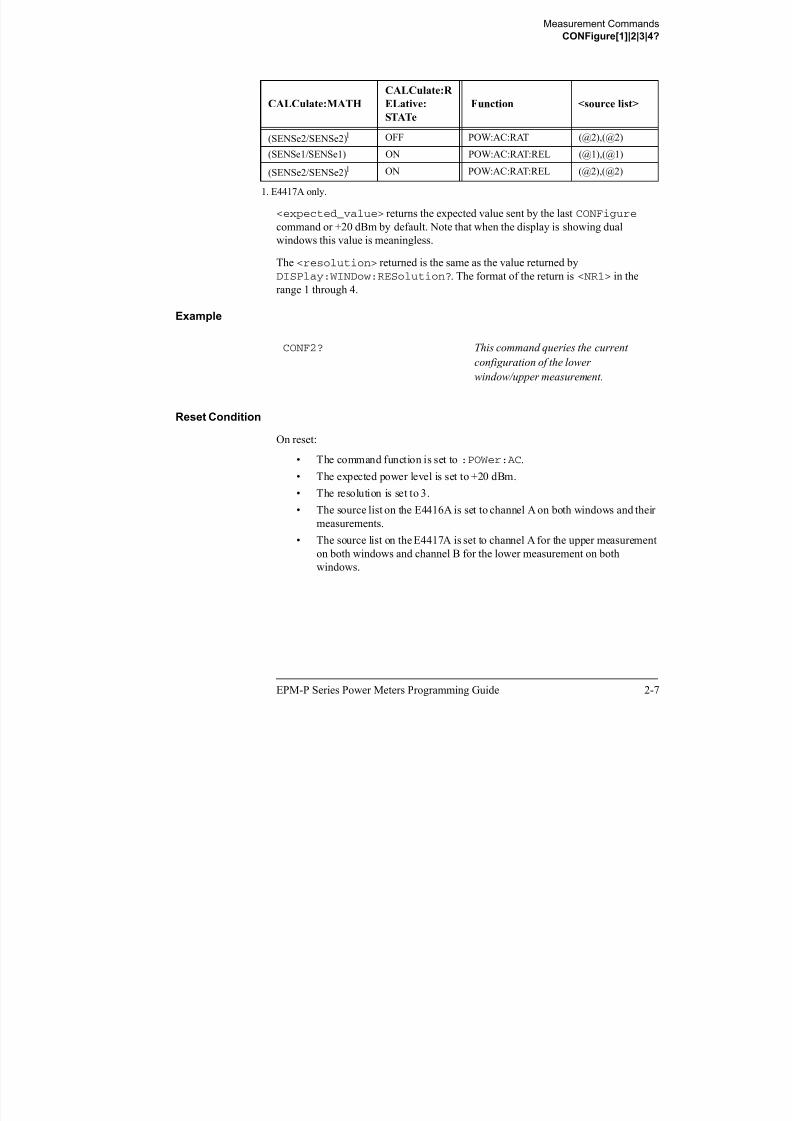
8/9/2019 E4416 Programming Guide
http://slidepdf.com/reader/full/e4416-programming-guide 151/615
EPM-P Series Power Meters Programming Guide 2-7
DISPlay:WINDow:RESolution?. The format of the return is <NR1> in the
range 1 through 4.
Example
Reset Condition
On reset:
• The command function is set to :POWer:AC.
• The expected power level is set to +20 dBm.
• The resolution is set to 3.
• The source list on the E4416A is set to channel A on both windows and their
measurements.
• The source list on the E4417A is set to channel A for the upper measurement
on both windows and channel B for the lower measurement on bothwindows.
CONF2? This command queries the current
configuration of the lower
window/upper measurement.
Measurement Commands
CONFigure[1]|2|3|4 Commands
CONFigure[1]|2|3|4 Commands
The CONFigure commands are used on the specified window/measurement to set:
• The expected power level being measured.
• The resolution of the window/measurement.
• The channel(s) on which the measurement is to be made.The CONFigure commands do not make the power measurement after setting the
configuration. Use READ?, or alternatively use INITiate followed by a FETCh?
to make the measurement.
The CONFigure command also applies the following defaults to the channel(s)
which are in the specified window (the channel(s) in the window are specified in the
<source list> parameter):

8/9/2019 E4416 Programming Guide
http://slidepdf.com/reader/full/e4416-programming-guide 152/615
2-8 EPM-P Series Power Meters Programming Guide
Default Settings Description
INITiate:CONTinuous OFF Sets the power meter to make one trigger cycle
when INITiate is sent.
TRIGger:SOURce IMMediate WhenTRIG:SOUR is set toBUS orHOLD, sets
the power meter to make the measurement
immediately a trigger is received.
TRIGger:DELay:AUTO ON Enables automatic delay before making the
measurement.
SENSE:AVERage:COUNt:AUTO ON Enables automatic filter length selection.
SENSE:AVERage:STATe ON Enables averaging.
Measurement Commands
CONFigure[1]|2|3|4[:SCALar][:POWer:AC] [<expected_value>[,<resolution>[,<source list>]]]
CONFigure[1]|2|3|4[:SCALar][:POWer:AC] [<expected_value>[,<resolution>[,<sourcelist>]]]
This command is used on the specified window/measurement to set:
• The expected power level of the measurement.
• The resolution of the window/measurement.
• The channel on which the measurement will be made.
Syntax
Space expected value resolution,
:POW :AC:SCAL
source list,
CONF 1
2
3

8/9/2019 E4416 Programming Guide
http://slidepdf.com/reader/full/e4416-programming-guide 153/615
EPM-P Series Power Meters Programming Guide 2-9
p p _
DEF
resolution,
DEF
source list,4
Measurement Commands
CONFigure[1]|2|3|4[:SCALar][:POWer:AC] [<expected_value>[,<resolution>[,<source list>]]]
Parameters
Refer to “Optional Parameters”, on page 2-3 for additional details on the parameters
in this command.
Item Description/Default Range of Values
expected_value A numeric value for the expected powerlevel. The units of measurement are
dBm and W. The default units are
defined by UNIT:POWer.
Sensor dependent.
DEF1
resolution A numeric value for the resolution. If
unspecified the current resolution
setting is used.
1 to 4 2
1.0, 0.1, 0.01, 0.001
DEF1

8/9/2019 E4416 Programming Guide
http://slidepdf.com/reader/full/e4416-programming-guide 154/615
2-10 EPM-P Series Power Meters Programming Guide
Example
1. The mnemonic DEF means DEFault. This is not equivalent to the DEFault parameter used in the
command sub-systems. The parameters must be entered in the specified order. If parameters areomitted, they will default from the right. The parameter DEFault is used as a place holder.
SpecifyingDEF leaves the parameter value unchanged.
DEF
2. When the measurement result is linear this parameter represents the number of significant digits.
When the measurement result is logarithmic 1 to 4 represents a resolution of 1, 0.1, 0.01 and 0.001
respectively.
source list The channel which the command is
implemented on.
If unspecified the current window setup
is used. However, on the E4417A, if the
window shows a ratio or difference
measurement, the upper window
defaults to channel A and the lower
window to channel B.
(@1)
(@2)3
3. E4417A only.
CONF1:POW:AC DEF,2,(@1) This command configures the upper
window/upper measurement to measure
the power of channel A, using the
current sensor range and a resolution
setting of 2.
Measurement Commands
CONFigure[1]|2|3|4[:SCALar][:POWer:AC]:RELative [<expected_value>[,<resolution>[,<source list>]]]
CONFigure[1]|2|3|4[:SCALar][:POWer:AC]:RELative[<expected_value>[,<resolution>[,<source list>]]]
This command sets the measurement function, range and resolution of the specified
window. It sets the measurement function to single channel with relative mode on.
The relative value used is that set by the
CALCulate:RELative:MAGNitude:AUTO command.
Syntax
:POW :AC:SCAL :REL
Space expected_value resolution, source list,
CONF 1
2
3
4

8/9/2019 E4416 Programming Guide
http://slidepdf.com/reader/full/e4416-programming-guide 155/615
EPM-P Series Power Meters Programming Guide 2-11
Parameters
Refer to “Optional Parameters”, on page 2-3 for additional details on the parameters
in this command.
Item Description/Default Range of Values
expected_value (for the expected
power level)
A numeric value for the expected powerlevel. The units of measurement are
dBm and W. The default units are
defined by UNIT:POWer.
sensor dependent
DEF1
resolution A numeric value for the resolution. If
unspecified the current resolution
setting is used.
1 to 4 2
1.0, 0.1, 0.01, 0.001
DEF1
source list The channel which the command is
implemented on.
If unspecified the current window setup
is used. However, on the E4417A, if the
window shows a ratio or difference
measurement, the upper window
defaults to channel A and the lower
window to channel B.
(@1)
(@2)3
DEF DEF
Measurement Commands
CONFigure[1]|2|3|4[:SCALar][:POWer:AC]:RELative [<expected_value>[,<resolution>[,<source list>]]]
Example
1. The mnemonic DEF means DEFault. This is not equivalent to the DEFault parameter used in
the command sub-systems. The parameters must be entered in the specified order. If parameters
are omitted, they will default from the right. The parameter DEFault is used as a place holder.
SpecifyingDEF leaves the parameter value unchanged.
2. When the measurement result is linear this parameter represents the number of significant
digits. When the measurement result is logarithmic 1 to 4 represents a resolution of 1, 0.1, 0.01
and 0.001 respectively.
3. E4417A only.
CONF2:REL -50DBM,3,(@1) This command configures the lower
window to measure the relative power
of channel A, using an expected power

8/9/2019 E4416 Programming Guide
http://slidepdf.com/reader/full/e4416-programming-guide 156/615
2-12 EPM-P Series Power Meters Programming Guide
f , g p p
level of -50 dBm and a resolution
setting of 3.
Measurement Commands
CONFigure[1]|2|3|4[:SCALar][:POWer:AC]:DIFFerence [<expected_value>[,<resolution>[,<source
list>]]]
CONFigure[1]|2|3|4[:SCALar][:POWer:AC]:DIFFerence[<expected_value>[,<resolution>[,<source list>]]]
This command sets the measurement function and resolution of the specified window.
It sets the measurement function to difference with relative mode off.
Syntax
:POW :AC:SCAL :DIFF
Space expected_value
DEF
resolution,
DEF
source list,
CONF 1
2
3
4

8/9/2019 E4416 Programming Guide
http://slidepdf.com/reader/full/e4416-programming-guide 157/615
EPM-P Series Power Meters Programming Guide 2-13
Parameters
Refer to “Optional Parameters”, on page 2-3 for additional details on the parameters
in this command.
Item Description/Default Range of Values
expected_value
(for the expected
power level)
The power meter ignores the numeric
value entered in this parameter. Any
value entered is treated like DEF.
sensor dependent
DEF1
resolution A numeric value for the resolution. If
unspecified the current resolution
setting is used.
1 to 4 2
1.0, 0.1, 0.01, 0.001
DEF1
source list This channel list specifies between
which channels the difference is
calculated.
If unspecified and the current window
setup is a difference measurement then
this difference setup is used, otherwise
it defaults to channel A-B (E4417A) or
A-A (E4416A).
(@1),(@2)3
(@2),(@1)3
(@1),(@1)
(@2),(@2)3
Measurement Commands
CONFigure[1]|2|3|4[:SCALar][:POWer:AC]:DIFFerence [<expected_value>[,<resolution>[,<source
list>]]]
Example
1. The mnemonic DEF means DEFault. This is not equivalent to the DEFault parameter used in
the command sub-systems. The parameters must be entered in the specified order. If parameters
are omitted, they will default from the right. The parameter DEFault is used as a place holder.
SpecifyingDEF leaves the parameter value unchanged.
2. When the measurement result is linear this parameter represents the number of significant
digits. When the measurement result is logarithmic 1 to 4 represents a resolution of 1, 0.1, 0.01
and 0.001 respectively.
3. E4417A only.
CONF2:DIFF DEF,1,(@2),(@1) This command configures the lower
window to make a difference
measurement of channel B - channel A,
using the current sensor range and a

8/9/2019 E4416 Programming Guide
http://slidepdf.com/reader/full/e4416-programming-guide 158/615
2-14 EPM-P Series Power Meters Programming Guide
using the current sensor range and a
resolution of 1 on both channels.
Measurement Commands
CONFigure[1]|2|3|4[:SCALar][:POWer:AC]:DIFFerence:RELative
[<expected_value>[,<resolution>[,<source list>]]]
CONFigure[1]|2|3|4[:SCALar][:POWer:AC]:DIFFerence:RELative
[<expected_value>[,<resolution>[,<source list>]]]
This command sets the measurement function, range and resolution of the specified
window. It sets the measurement function to difference with relative mode on. The
relative value used is set by the CALCulate:RELative:MAGNitude:AUTO
command.
Syntax
:POW :AC:SCAL :DIFF :REL
Space expected_value
DEF
resolution,
DEF
source list,
CONF 1
2
3
4

8/9/2019 E4416 Programming Guide
http://slidepdf.com/reader/full/e4416-programming-guide 159/615
EPM-P Series Power Meters Programming Guide 2-15
Parameters
Refer to “Optional Parameters”, on page 2-3 for additional details on the parameters
in this command.
Item Description/Default Range of Values
expected_value
(for the expected
power level)
The power meter ignores the numeric
value entered in this parameter. Any
value entered is treated like DEF.
sensor dependent
DEF1
resolution A numeric value for the resolution. If
unspecified the current resolution
setting is used.
1 to 4 2
1.0, 0.1, 0.01, 0.001
DEF1
source list This channel list specifies the channels
used to calculate the difference.If unspecified and the current window
setup is a difference measurement then
this difference setup is used, otherwise
it defaults to channel A-B (E4417A) or
A-A (E4416A).
(@1),(@2)3
(@2),(@1)3
(@1),(@1)
(@2),(@2)3
DEF DEF
Measurement Commands
CONFigure[1]|2|3|4[:SCALar][:POWer:AC]:DIFFerence:RELative
[<expected_value>[,<resolution>[,<source list>]]]
Example
1. The mnemonic DEF means DEFault. This is not equivalent to the DEFault parameter used in
the command sub-systems. The parameters must be entered in the specified order. If parameters
are omitted, they will default from the right. The parameter DEFault is used as a place holder.
SpecifyingDEF leaves the parameter value unchanged.
2. When the measurement result is linear this parameter represents the number of significant
digits. When the measurement result is logarithmic 1 to 4 represents a resolution of 1, 0.1, 0.01
and 0.001 respectively.
3. E4417A only.
CONF1:DIFF:REL DEF,1,(@1),(@2) This command configures the upper
window to make a difference
measurement of channel A - channel B
with relative mode on using the

8/9/2019 E4416 Programming Guide
http://slidepdf.com/reader/full/e4416-programming-guide 160/615
2-16 EPM-P Series Power Meters Programming Guide
with relative mode on, using the
current sensor range and a resolutionof 1 on both channels.
Measurement Commands
CONFigure[1]|2|3|4[:SCALar][:POWer:AC]:RATio [<expected_value>[,<resolution>[,<source list>]]]
CONFigure[1]|2|3|4[:SCALar][:POWer:AC]:RATio[<expected_value>[,<resolution>[,<source list>]]]
This command sets the measurement function, range and resolution of the specified
window. It sets the measurement function to ratio with relative mode off.
Syntax
:POW :AC:SCAL :RAT
Space expected_value
DEF
resolution,
DEF
source list,
CONF 1
2
3
4

8/9/2019 E4416 Programming Guide
http://slidepdf.com/reader/full/e4416-programming-guide 161/615
EPM-P Series Power Meters Programming Guide 2-17
Parameters
Refer to “Optional Parameters”, on page 2-3 for additional details on the parameters
in this command.
Item Description/Default Range of Values
expected_value
(for the expected
power level)
The power meter ignores the numeric
value entered in this parameter. Any
value entered is treated like DEF.
sensor dependent
DEF1
1. The mnemonic DEF means DEFault. This is not equivalent to the DEFault parameter used in
the command sub-systems. The parameters must be entered in the specified order. If parameters
are omitted, they will default from the right. The parameter DEFault is used as a place holder.
SpecifyingDEF leaves the parameter value unchanged.
resolution A numeric value for the resolution. If
unspecified the current resolution
setting is used.
1 to 4 2
1.0, 0.1, 0.01, 0.001
DEF1
source list This channel list specifies the channels
used to calculate the ratio. If unspecified
and the current window setup is a ratio
measurement then this ratio setup is
used, otherwise it defaults to channel
A/B (E4417A) or A/A (E4416A).
(@1),(@2)3
(@2),(@1)3
(@1),(@1)
(@2),(@2)3
Measurement Commands
CONFigure[1]|2|3|4[:SCALar][:POWer:AC]:RATio [<expected_value>[,<resolution>[,<source list>]]]
Example
2. When the measurement result is linear this parameter represents the number of significant
digits. When the measurement result is logarithmic 1 to 4 represents a resolution of 1, 0.1, 0.01
and 0.001 respectively.
3. E4417A only.
CONF1:RAT DEF,4,(@1),(@2) This command configures the upper
window to make a ratio measurement of
channel A over channel B, using the
current sensor range and a resolution
setting of 4 on both channels.

8/9/2019 E4416 Programming Guide
http://slidepdf.com/reader/full/e4416-programming-guide 162/615
2-18 EPM-P Series Power Meters Programming Guide
Measurement Commands
CONFigure[1]|2|3|4[:SCALar][:POWer:AC]:RATio:RELative [<expected_value>[,<resolution>[,<source
list>]]]
CONFigure[1]|2|3|4[:SCALar][:POWer:AC]:RATio:RELative[<expected_value>[,<resolution>[,<source list>]]]
This command sets the measurement function, range and resolution of the specified
window. It sets the measurement function to ratio with relative mode on. The relative
value used is that set by the CALCulate:RELative:MAGNitude:AUTO
command.
Syntax
:POW :AC:SCAL :RAT :REL
Space expected_value
DEF
resolution,
DEF
source list,
CONF 1
2
3
4

8/9/2019 E4416 Programming Guide
http://slidepdf.com/reader/full/e4416-programming-guide 163/615
EPM-P Series Power Meters Programming Guide 2-19
Parameters
Refer to “Optional Parameters”, on page 2-3 for additional details on the parameters
in this command.
Item Description/Default Range of Values
expected_value (for the expected
power level)
The power meter ignores the numericvalue entered in this parameter. Any
value entered is treated like DEF.
sensor dependent
DEF1
resolution A numeric value for the resolution. If
unspecified the current resolution
setting is used.
1 to 4 2
1.0, 0.1, 0.01, 0.001
DEF1
source list This channel list specifies the channels
used to calculate the ratio.If unspecified and the current window
setup is a ratio measurement then this
ratio setup is used, otherwise it defaults
to channel A/B (E4417A) or A/A
(E4416A).
(@1),(@2)3
(@2),(@1)3
(@1),(@1)
(@2),(@2)3
Measurement Commands
CONFigure[1]|2|3|4[:SCALar][:POWer:AC]:RATio:RELative [<expected_value>[,<resolution>[,<source
list>]]]
Example
1. The mnemonic DEF means DEFault. This is not equivalent to the DEFault parameter used in
the command sub-systems. The parameters must be entered in the specified order. If parameters
are omitted, they will default from the right. The parameter DEFault is used as a place holder.
SpecifyingDEF leaves the parameter value unchanged.
2. When the measurement result is linear this parameter represents the number of significant
digits. When the measurement result is logarithmic 1 to 4 represents a resolution of 1, 0.1, 0.01
and 0.001 respectively.
3. E4417A only.
CONF1:RAT:REL DEF,1,(@1),(@2) This command configures the upper
window to make a ratio measurement of
channel A over channel B with relative
mode on, using the current sensor

8/9/2019 E4416 Programming Guide
http://slidepdf.com/reader/full/e4416-programming-guide 164/615
2-20 EPM-P Series Power Meters Programming Guide
range and a resolution setting of 1 onboth channels.
Measurement Commands
FETCh[1]|2|3|4 Queries
FETCh[1]|2|3|4 Queries
The FETCh? queries set the specified window’s measurement function to either
single channel, difference or ratio measurements with relative mode either off or on.
They then recalculate the measurement and place the result on the bus. The format of
the result is set by FORM[:READ][:DATA]. Refer to chapter 6, Format, for further
information.
The query returns a measurement result whenever it is valid. The measurement result
becomes invalid under the following conditions:
• When *RST is executed.
• Whenever a measurement is initiated.
• When any SENSe parameter, such as frequency, is changed.
If data is invalid, the FETCh? query is not completed until all data is valid. The
exceptions to this are, if the power meter is in the idle state and the data is invalid, or

8/9/2019 E4416 Programming Guide
http://slidepdf.com/reader/full/e4416-programming-guide 165/615
EPM-P Series Power Meters Programming Guide 2-21
p , p ,
the power meter has been reconfigured as defined above and no new measurementhas been initiated. In such cases, the FETCh? routine generates the error -230, “Data
corrupt or stale” and no result is returned. A common cause for this error is receiving
a FETCh? after a *RST. If the expected value and resolution parameters are not the
same as those that were used to collect the data, error -221, “Settings conflict” occurs.
Note When TRIG:SOUR is INT1, INT2 or EXT and a new acquisition has been
initiated (using the INIT command for example), FETCH? waits until the
trigger takes place before executing. If trigger conditions are not
satisfied—when the trigger level differs greatly from the signal level forexample—this can give the impression that the power meter has hung.
To ‘unlock’ the power meter and adjust trigger settings, a GPIB bus execute
clear must be performed.
Measurement Commands
FETCh[1]|2|3|4[:SCALar][:POWer:AC]? [<expected_value>[,<resolution>[,<source list>]]]
FETCh[1]|2|3|4[:SCALar][:POWer:AC]? [<expected_value>[,<resolution>[,<source list>]]]
This command sets the specified window’s measurement function to single channel
with relative mode off, recalculates the measurement and places the result on the bus.
The result is a power based measurement and is expressed in the units defined by
UNIT[1]|2|3|4:POWer.
Syntax:POW :AC ?:SCAL
Space expected_value
DEF
resolution,
DEF
source list,
FETC 1
2
3
4

8/9/2019 E4416 Programming Guide
http://slidepdf.com/reader/full/e4416-programming-guide 166/615
2-22 EPM-P Series Power Meters Programming Guide
Parameters
Refer to “Optional Parameters”, on page 2-3 for additional details on the parameters
in this command.
Item Description/Default Range of Values
expected_value
(for the expected power level)
The expected power level parameter can
be set toDEF or a numeric value. If avalue is entered it should correspond to
that set by CONFigure otherwise an
error occurs. The units of measurement
are dBm and W. The default units are
defined by UNIT:POWer.
sensor dependent
DEF1
resolution A numeric value for the resolution. If it
is unspecified the current resolution
setting is used. If a value is entered it
should correspond to the currentresolution setting otherwise an error
occurs.
1 to 4 2
1.0, 0.1, 0.01, 0.001
DEF1
Measurement Commands
FETCh[1]|2|3|4[:SCALar][:POWer:AC]? [<expected_value>[,<resolution>[,<source list>]]]
source list The channel which the command is
implemented on. If unspecified the
current window setup is used. However,
on the E4417A, if the window shows a
ratio or difference measurement, the
upper window defaults to channel A and
the lower window to channel B.
(@1)
(@2) (E4417A only)
1. The mnemonic DEF means DEFault. This is not equivalent to the DEFault parameter used in
the command sub-systems. The parameters must be entered in the specified order. If parameters
are omitted, they will default from the right. The parameter DEFault is used as a place holder.
SpecifyingDEF leaves the parameter value unchanged.
2. When the measurement result is linear this parameter represents the number of significant
digits. When the measurement result is logarithmic 1 to 4 represents a resolution of 1, 0.1, 0.01
and 0.001 respectively.
Item Description/Default Range of Values

8/9/2019 E4416 Programming Guide
http://slidepdf.com/reader/full/e4416-programming-guide 167/615
EPM-P Series Power Meters Programming Guide 2-23
Example
Error Messages
• If the last measurement is not valid error -230, “Data corrupt or stale” occurs. Ameasurement is valid after it has been initiated. It becomes invalid when either a
reset occurs or any measurement parameter, for example frequency, is changed.
• If the expected_value and resolution parameters are not the same as the current
expected value and resolution setting on the specified window, error -221,
“Settings conflict” occurs.
FETC2:POW:AC? This command queries the lower
window’s measurement result.
Measurement Commands
FETCh[1]|2|3|4[:SCALar][:POWer:AC]:RELative? [<expected_value>[,<resolution>[,<source list>]]]
FETCh[1]|2|3|4[:SCALar][:POWer:AC]:RELative?[<expected_value>[,<resolution>[,<source list>]]]
This command sets the specified window’s measurement function to single channel
with relative mode on, recalculates the measurement and places the results on the bus.
The result is a ratio based measurement and is expressed in the units defined by
UNIT[1]|2|3|4:POWer:RATio. The relative value used is that set by the
CALCulate:RELative:MAGNitude:AUTO command.
Syntax
:POW :AC ?:SCAL :REL
Space expected_value
DEF
resolution, source list,
FETC 1
2
3
4

8/9/2019 E4416 Programming Guide
http://slidepdf.com/reader/full/e4416-programming-guide 168/615
2-24 EPM-P Series Power Meters Programming Guide
Parameters
Refer to “Optional Parameters”, on page 2-3 for additional details on the parameters
in this command.
Item Description/Default Range of Values
expected_value
(for the expected
power level)
The expected power level parameter can
be set toDEF or a numeric value. If a
value is entered it should correspond to
that set by CONFigure otherwise an
error occurs. The units of measurement
are dBm and W. The default units are
defined by UNIT:POWer.
sensor dependent
DEF1
resolution A numeric value for the resolution. If it
is unspecified the current resolutionsetting is used. If a value is entered it
should correspond to the current
resolution setting otherwise an error
occurs.
1 to 4 2
1.0, 0.1, 0.01, 0.001
DEF1
DEFDEF
Measurement Commands
FETCh[1]|2|3|4[:SCALar][:POWer:AC]:RELative? [<expected_value>[,<resolution>[,<source list>]]]
source list The channel which the command is
implemented on. If unspecified the
current window setup is used. However,
on the E4417A, if the window shows a
ratio or difference measurement, the
upper window defaults to channel A and
the lower window to channel B.
(@1)
(@2) (E4417A only)
1. The mnemonic DEF means DEFault. This is not equivalent to the DEFault parameter used in
the command sub-systems. The parameters must be entered in the specified order. If parameters
are omitted, they will default from the right. The parameter DEFault is used as a place holder.
SpecifyingDEF leaves the parameter value unchanged.
2. When the measurement result is linear this parameter represents the number of significant
digits. When the measurement result is logarithmic 1 to 4 represents a resolution of 1, 0.1, 0.01
and 0.001 respectively.
Item Description/Default Range of Values

8/9/2019 E4416 Programming Guide
http://slidepdf.com/reader/full/e4416-programming-guide 169/615
EPM-P Series Power Meters Programming Guide 2-25
Example
FETC1:REL? DEF,2,(@2) This command queries the upper
window’s relative measurement of
channel B, using the current sensor
range and a resolution setting of 2.

8/9/2019 E4416 Programming Guide
http://slidepdf.com/reader/full/e4416-programming-guide 170/615
Measurement Commands
FETCh[1]|2|3|4[:SCALar][:POWer:AC]:DIFFerence? [<expected_value>[,<resolution>[,<source list>]]]
FETCh[1]|2|3|4[:SCALar][:POWer:AC]:DIFFerence?[<expected_value>[,<resolution>[,<source list>]]]
This command sets the specified window’s measurement function to power difference
with relative mode off, recalculates the measurement and places the results on the
bus. The result is a power based measurement and is expressed in the units defined by
UNIT[1]|2|3|4:POWer.
Syntax
:POW :AC:SCAL :DIFF ?
Space expected_value
DEF
resolution,
DEF
source list,
FETC 1
2
3
4

8/9/2019 E4416 Programming Guide
http://slidepdf.com/reader/full/e4416-programming-guide 171/615
EPM-P Series Power Meters Programming Guide 2-27
Parameters
Refer to “Optional Parameters”, on page 2-3 for additional details on the parameters
in this command.
Item Description/Default Range of Values
expected_value
(for the expected
power level)
The expected power level parameter can
be set toDEF or a numeric value. If a
value is entered it should correspond to
that set by CONFigure otherwise an
error occurs.The units of measurement
are dBm and W. The default units are
defined by UNIT:POWer.
sensor dependent
DEF1
resolution A numeric value for the resolution. If it
is unspecified the current resolution
setting is used. If a value is entered itshould correspond to the current
resolution setting otherwise an error
occurs.
1 to 4 2
1.0, 0.1, 0.01, 0.001
DEF1
Measurement Commands
FETCh[1]|2|3|4[:SCALar][:POWer:AC]:DIFFerence? [<expected_value>[,<resolution>[,<source list>]]]
source list This channel list specifies the channels
used to calculate the difference.
If unspecified and the current window
setup is a difference measurement then
this difference setup is used, otherwise it
defaults to channel A-B (E4417A) or
A-A (E4416A).
(@1),(@2)3
(@2),(@1)3
(@1),(@1)
(@2),(@2)3
1. The mnemonic DEF means DEFault. This is not equivalent to the DEFault parameter used in
the command sub-systems. The parameters must be entered in the specified order. If parameters
are omitted, they will default from the right. The parameter DEFault is used as a place holder.
SpecifyingDEF leaves the parameter value unchanged.
2. When the measurement result is linear this parameter represents the number of significant
digits. When the measurement result is logarithmic 1 to 4 represents a resolution of 1, 0.1, 0.01
and 0.001 respectively.
3 E4417A only
Item Description/Default Range of Values

8/9/2019 E4416 Programming Guide
http://slidepdf.com/reader/full/e4416-programming-guide 172/615
2-28 EPM-P Series Power Meters Programming Guide
Example
Error Messages
• If the last measurement on either channel is not valid error -230, “Data corrupt or
stale” occurs. A measurement is valid after it has been initiated. It becomes invalid
when either a reset occurs or any measurement parameter, for example frequency,
is changed.
• If the expected_value and resolution parameters are not the same as the current
expected value and resolution settings on the specified window, error -221,
“Settings conflict” occurs.
3. E4417A only.
FETC2:DIFF? This command queries the difference
measurement on the lower window.
Measurement Commands
FETCh[1]|2|3|4[:SCALar][:POWer:AC]:DIFFerence:RELative?
[<expected_value>[,<resolution>[,<source list>]]]
FETCh[1]|2|3|4[:SCALar][:POWer:AC]:DIFFerence:RELative?[<expected_value>[,<resolution>[,<source list>]]]
This command sets the specified window’s measurement function to power difference
with relative mode on, recalculates the measurement and places the results on the bus.
The result is a ratio based measurement and is expressed in the units defined by
UNIT[1]|2|3|4:POWer:RATio. The relative value used is that set by the
CALCulate:RELative:MAGNitude:AUTO command.
Syntax
:POW :AC:SCAL :DIFF :REL ?
Space expected_value
DEF
resolution,
DEF
source list,
FETC 1
2
3
4

8/9/2019 E4416 Programming Guide
http://slidepdf.com/reader/full/e4416-programming-guide 173/615
EPM-P Series Power Meters Programming Guide 2-29
Parameters
Refer to “Optional Parameters”, on page 2-3 for additional details on the parameters
in this command.
Item Description/Default Range of Values
expected_value
(for the expected
power level)
The expected power level parameter can
be set toDEF or a numeric value. If a
value is entered it should correspond to
that set by CONFigure otherwise an
error occurs.The units of measurement
are dBm and W. The default units are
defined by UNIT:POWer.
sensor dependent
DEF1
resolution A numeric value for the resolution. If it
is unspecified the current resolutionsetting is used. If a value is entered it
should correspond to the current
resolution setting otherwise an error
occurs.
1 to 4 2
1.0, 0.1, 0.01, 0.001
DEF1

8/9/2019 E4416 Programming Guide
http://slidepdf.com/reader/full/e4416-programming-guide 174/615
Measurement Commands
FETCh[1]|2|3|4[:SCALar][:POWer:AC]:RATio? [<expected_value>[,<resolution>[,<source list>]]]
FETCh[1]|2|3|4[:SCALar][:POWer:AC]:RATio?[<expected_value>[,<resolution>[,<source list>]]]
This command sets the specified window’s measurement function to power ratio with
relative mode off, recalculates the measurement and places the results on the bus. The
result is a ratio based measurement and is expressed in the units defined by
UNIT[1]|2|3|4:POWer:RATio.
Syntax
:POW :AC:SCAL :RAT ?
Space expected_value
DEF
resolution,
DEF
source list,
FETC 1
2
3
4

8/9/2019 E4416 Programming Guide
http://slidepdf.com/reader/full/e4416-programming-guide 175/615
EPM-P Series Power Meters Programming Guide 2-31
Parameters
Refer to “Optional Parameters”, on page 2-3 for additional details on the parameters
in this command.
Item Description/Default Range of Values
expected_value (for the expected
power level)
The expected power level parameter can be set toDEF or a numeric value. If a
value is entered it should correspond to
that set by CONFigure otherwise an
error occurs. The units of measurement
are dBm and W. The default units are
defined by UNIT:POWer.
sensor dependent
DEF1
resolution A numeric value for the resolution. If it
is unspecified the current resolution
setting is used. If a value is entered itshould correspond to the current
resolution setting otherwise an error
occurs.
1 to 4 2
1.0, 0.1, 0.01, 0.001
DEF1
Measurement Commands
FETCh[1]|2|3|4[:SCALar][:POWer:AC]:RATio? [<expected_value>[,<resolution>[,<source list>]]]
source list This channel list specifies the channels
used to calculate the ratio.
If unspecified and the current window
setup is a ratio measurement then this
ratio setup is used, otherwise it defaults
to channel A/B (E4417A) or A/A(E4416A).
(@1),(@2)3
(@2),(@1)3
(@1),(@1)
(@2),(@2)
3
1. The mnemonic DEF means DEFault. This is not equivalent to the DEFault parameter used in
the command sub-systems. The parameters must be entered in the specified order. If parameters
are omitted, they will default from the right. The parameter DEFault is used as a place holder.
SpecifyingDEF leaves the parameter value unchanged.
2. When the measurement result is linear this parameter represents the number of significant
digits. When the measurement result is logarithmic 1 to 4 represents a resolution of 1, 0.1, 0.01
and 0.001 respectively.
3. E4417A only.
Item Description/Default Range of Values

8/9/2019 E4416 Programming Guide
http://slidepdf.com/reader/full/e4416-programming-guide 176/615
2-32 EPM-P Series Power Meters Programming Guide
Example
Error Messages
• If the last measurement on either channel is not valid error -230, “Data corrupt or
stale” occurs. A measurement is valid after it has been initiated. It becomes invalid
when either a reset occurs or any measurement parameter, for example frequency,
is changed.
• If the expected_value and resolution parameters are not the same as the current
expected value and resolution settings on the specified window, error -221,“Settings conflict” occurs.
FETC2:RAT? DEF,1,(@1),(@2) This command queries the lower
window’s ratio measurement of
channel A over channel B, using the
current sensor range and a resolution
of 1 on both channels.
Measurement Commands
FETCh[1]|2|3|4[:SCALar][:POWer:AC]:RATio:RELative? [<expected_value>[,<resolution>[,<source
list>]]]
FETCh[1]|2|3|4[:SCALar][:POWer:AC]:RATio:RELative?[<expected_value>[,<resolution>[,<source list>]]]
This command sets the specified window’s measurement function to power ratio with
relative mode on, recalculates the measurement and places the results on the bus. The
result is a ratio based measurement and is expressed in the units defined by
UNIT[1]|2|3|4:POWer:RATio. The relative value used is that set by the
CALCulate:RELative:MAGNitude:AUTO command.
Syntax
:POW :AC:SCAL :RAT :REL ?
Space expected_value
DEF
resolution,
DEF
source list,
FETC 1
2
3
4
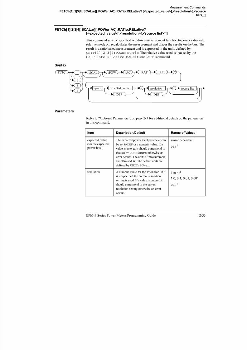
8/9/2019 E4416 Programming Guide
http://slidepdf.com/reader/full/e4416-programming-guide 177/615
EPM-P Series Power Meters Programming Guide 2-33
Parameters
Refer to “Optional Parameters”, on page 2-3 for additional details on the parameters
in this command.
Item Description/Default Range of Values
expected_value
(for the expected
power level)
The expected power level parameter can
be set toDEF or a numeric value. If a
value is entered it should correspond to
that set by CONFigure otherwise an
error occurs. The units of measurement
are dBm and W. The default units are
defined by UNIT:POWer.
sensor dependent
DEF1
resolution A numeric value for the resolution. If it
is unspecified the current resolutionsetting is used. If a value is entered it
should correspond to the current
resolution setting otherwise an error
occurs.
1 to 4 2
1.0, 0.1, 0.01, 0.001
DEF1
Measurement Commands
FETCh[1]|2|3|4[:SCALar][:POWer:AC]:RATio:RELative? [<expected_value>[,<resolution>[,<source
list>]]]
source list This channel list specifies the channels
used to calculate the ratio.
If unspecified and the current window
setup is a ratio measurement then this
ratio setup is used, otherwise it defaults
to channel A/B (E4417A) or A/A(E4416A).
(@1),(@2)3
(@2),(@1)3
(@1),(@1)
(@2),(@2)
3
1. The mnemonic DEF means DEFault. This is not equivalent to the DEFault parameter used in
the command sub-systems. The parameters must be entered in the specified order. If parameters
are omitted, they will default from the right. The parameter DEFault is used as a place holder.
SpecifyingDEF leaves the parameter value unchanged.
2. When the measurement result is linear this parameter represents the number of significant
digits. When the measurement result is logarithmic 1 to 4 represents a resolution of 1, 0.1, 0.01
and 0.001 respectively.
3. E4417A only.
Item Description/Default Range of Values

8/9/2019 E4416 Programming Guide
http://slidepdf.com/reader/full/e4416-programming-guide 178/615
2-34 EPM-P Series Power Meters Programming Guide
Example
Error Messages
• If the last measurement on either channel is not valid error -230, “Data corrupt or
stale” occurs. A measurement is valid after it has been initiated. It becomes invalid
when either a reset occurs or any measurement parameter, for example frequency,
is changed.
• If the expected_value and resolution parameters are not the same as the current
expected value and resolution settings on the specified window, error -221,
“Settings conflict” occurs.
FETC:RAT:REL? This command queries the relative ratio measurement on the
upper window.
Measurement Commands
READ[1]|2|3|4 Commands
READ[1]|2|3|4 Commands
The READ? commands are most commonly used with the CONFigure command to
cause a new power measurement to be taken and the result returned to the output
buffer. The format of the result is set byFORM[:READ][:DATA]. Refer to chapter
6, Format, for further information.
.• For the E4416A theREAD? query is equivalent to:
ABORtINITiateFETCh?
• For the E4417A carrying out a single channel measurement the READ?
queries are equivalent to:
ABORt1INITiate1
FETCh1?

8/9/2019 E4416 Programming Guide
http://slidepdf.com/reader/full/e4416-programming-guide 179/615
EPM-P Series Power Meters Programming Guide 2-35
or
ABORt2INITiate2FETCh2?
• For the E4417A carrying out a difference measurement the
READ:DIFFerence? queries are equivalent to:
ABORt1and
ABORt2INITiate1INITiate2FETCh:DIFFerence?
• For the E4417A carrying out a ratio measurement theREAD:RATio?
queries are equivalent to:
ABORt1ABORt2INITiate1
INITiate2FETCh:RATio?
Measurement Commands
READ[1]|2|3|4[:SCALar][:POWer:AC]? [<expected_value>[,<resolution>[,<source list>]]]
READ[1]|2|3|4[:SCALar][:POWer:AC]? [<expected_value>[,<resolution>[,<source list>]]]
This command sets the specified window’s measurement function to single channel
with relative mode off, aborts then initiates the specified channel, calculates the
measurement result and places the result on the bus. The result is a power based
measurement and is expressed in the units defined by UNIT[1]|2|3|4:POWer.
Note INITiate:CONTinuous must be set to OFF, otherwise error -213, “INITignored” occurs. If TRIGger:SOURce is set to BUS, error -214, “Trigger
deadlock” occurs.
Syntax
:POW :AC:SCAL ?
Space expected value resolution, source list
READ 1
2
3

8/9/2019 E4416 Programming Guide
http://slidepdf.com/reader/full/e4416-programming-guide 180/615
2-36 EPM-P Series Power Meters Programming Guide
Parameters
Refer to “Optional Parameters”, on page 2-3 for additional details on the parameters
in this command.
Item Description/Default Range of Values
expected_value
(for the expected
power level)
The expected power level parameter can
be set toDEF or a numeric value. If a
value is entered it should correspond to
that set by CONFigure otherwise an
error occurs.
sensor dependent
DEF1
resolution A numeric value for the resolution. If it
is unspecified the current resolution
setting is used. If a value is entered it
should correspond to the current
resolution setting otherwise an error
occurs.
1 to 4 2
1.0, 0.1, 0.01, 0.001
DEF1
Space expected_value
DEF
resolution,
DEF
source list,4
Measurement Commands
READ[1]|2|3|4[:SCALar][:POWer:AC]? [<expected_value>[,<resolution>[,<source list>]]]
source list The channel which the command is
implemented on.
If unspecified the current window setup
is used. However, on the E4417A, if the
window shows a ratio or difference
measurement, the upper windowdefaults to channel A and the lower
window to channel B.
(@1)
(@2) (E4417A only)
1. The mnemonic DEF means DEFault. This is not equivalent to the DEFault parameter used in
the command sub-systems. The parameters must be entered in the specified order. If parameters
are omitted, they will default from the right. The parameter DEFault is used as a place holder.
SpecifyingDEF leaves the parameter value unchanged.
2. When the measurement result is linear this parameter represents the number of significant
digits. When the measurement result is logarithmic 1 to 4 represents a resolution of 1, 0.1, 0.01
and 0.001 respectively.
Item Description/Default Range of Values

8/9/2019 E4416 Programming Guide
http://slidepdf.com/reader/full/e4416-programming-guide 181/615
EPM-P Series Power Meters Programming Guide 2-37
Example
Error Messages
• INITiate:CONTinuous must be set to OFF, otherwise error -213, “INIT
ignored” occurs.
• If TRIGger:SOURce is set to BUS or HOLD, error -214, “Trigger deadlock”
occurs.
• If the expected value and resolution parameters are not the same as the current
expected value and resolution settings on the specified window, error -221,
“Settings conflict” occurs.
READ2:POW:AC? This command queries the lower
window’s measurement.
Measurement Commands
READ[1]|2|3|4[:SCALar][:POWer:AC]:RELative? [<expected_value>[,<resolution>[,<source list>]]]
READ[1]|2|3|4[:SCALar][:POWer:AC]:RELative?[<expected_value>[,<resolution>[,<source list>]]]
This command sets the specified window’s measurement function to single channel
with relative mode on, aborts then initiates the specified channel, calculates the
measurement result and places the result on the bus. The result is a ratio based
measurement and is expressed in the units defined by
UNIT[1]|2|3|4:POWer:RATio. The relative value used is that set by theCALCulate:RELative:MAGNitude:AUTO command.
Note INITiate:CONTinuous must be set to OFF, otherwise error -213, “INIT
ignored” occurs. If TRIGger:SOURce is set to BUS, error -214, “Trigger
deadlock” occurs.
Syntax
:POW :AC ?:SCAL :RELREAD 1

8/9/2019 E4416 Programming Guide
http://slidepdf.com/reader/full/e4416-programming-guide 182/615
2-38 EPM-P Series Power Meters Programming Guide
Parameters
Refer to “Optional Parameters”, on page 2-3 for additional details on the parameters
in this command.
Item Description/Default Range of Values
expected_value
(for the expected
power level)
The expected power level parameter can
be set toDEF or a numeric value. If a
value is entered it should correspond tothat set by CONFigure otherwise an
error occurs.
sensor dependent
DEF1
Space expected_value
DEF
resolution,
DEF
source list,
2
3
4
Measurement Commands
READ[1]|2|3|4[:SCALar][:POWer:AC]:RELative? [<expected_value>[,<resolution>[,<source list>]]]
resolution A numeric value for the resolution. If it
is unspecified the current resolution
setting is used. If a value is entered it
should correspond to the current
resolution setting otherwise an error
occurs.
1 to 4 2
1.0, 0.1, 0.01, 0.001
DEF1
source list The channel which the command is
implemented on.
If unspecified the current window setup
is used. However, on the E4417A, if the
window shows a ratio or difference
measurement, the upper window
defaults to channel A and the lower
window to channel B.
(@1)
(@2) (E4417A only)
1. The mnemonic DEF means DEFault. This is not equivalent to the DEFault parameter used in
the command sub systems The parameters must be entered in the specified order If parameters
Item Description/Default Range of Values

8/9/2019 E4416 Programming Guide
http://slidepdf.com/reader/full/e4416-programming-guide 183/615
EPM-P Series Power Meters Programming Guide 2-39
Example
the command sub-systems. The parameters must be entered in the specified order. If parameters
are omitted, they will default from the right. The parameter DEFault is used as a place holder.
SpecifyingDEF leaves the parameter value unchanged.
2. When the measurement result is linear this parameter represents the number of significant
digits. When the measurement result is logarithmic 1 to 4 represents a resolution of 1, 0.1, 0.01
and 0.001 respectively.
READ1:REL? DEF,1,(@2) This command queries the upper
window’s relative measurement of
channel B, using the current sensor
range and a resolution of 1.
Measurement Commands
READ[1]|2|3|4[:SCALar][:POWer:AC]:RELative? [<expected_value>[,<resolution>[,<source list>]]]
Error Messages
• INITiate:CONTinuous must be set to OFF, otherwise error -213, “INIT
ignored” occurs.
• If TRIGger:SOURce is set to BUS or HOLD, error -214, “Trigger deadlock”
occurs.
• If the expected value and resolution parameters are not the same as the current
expected value and resolution settings on the specified window, error -221,
“Settings conflict” occurs.

8/9/2019 E4416 Programming Guide
http://slidepdf.com/reader/full/e4416-programming-guide 184/615
2-40 EPM-P Series Power Meters Programming Guide
Measurement Commands
READ[1]|2|3|4[:SCALar][:POWer:AC]:DIFFerence? [<expected_value>[,<resolution>[,<source list>]]]
READ[1]|2|3|4[:SCALar][:POWer:AC]:DIFFerence?[<expected_value>[,<resolution>[,<source list>]]]
This command sets the specified window’s measurement function to difference mode
with relative mode off, aborts then initiates both channel A and B, calculates the
difference measurement result and places the result on the bus. The result is a power
based measurement and is expressed in the units defined by
UNIT[1]|2|3|4:POWer.
Note INITiate:CONTinuous must be set to OFF on both channels, otherwise
error -213, “INIT ignored” occurs. If TRIGger:SOURce is set to BUS on
either channel, error -214, “Trigger deadlock” occurs.
Syntax
:POW :AC ?:SCAL :DIFFREAD 1
2

8/9/2019 E4416 Programming Guide
http://slidepdf.com/reader/full/e4416-programming-guide 185/615
EPM-P Series Power Meters Programming Guide 2-41
Parameters
Refer to “Optional Parameters”, on page 2-3 for additional details on the parameters
in this command.
Item Description/Default Range of Values
expected_value
(for the expected
power level)
The power meter ignores the numeric
value entered in this parameter. Any
value entered is treated like DEF.
sensor dependent
DEF1
resolution A numeric value for the resolution. If it
is unspecified the current resolution
setting is used. If a value is entered it
should correspond to the current
resolution setting otherwise an error
occurs.
1 to 4 2
1.0, 0.1, 0.01, 0.001
DEF1
Space expected_value
DEF
resolution,
DEF
source list,3
4
Measurement Commands
READ[1]|2|3|4[:SCALar][:POWer:AC]:DIFFerence? [<expected_value>[,<resolution>[,<source list>]]]
E ample
source list This channel list specifies the channels
used to calculate the difference.
If unspecified and the current window
setup is a difference measurement then
this difference setup is used, otherwise
it defaults to channel A-B (E4417A) orA-A (E4416A).
(@1),(@2)3
(@2),(@1)3
(@1),(@1)
(@2),(@2)3
1. The mnemonic DEF means DEFault. This is not equivalent to the DEFault parameter used in
the command sub-systems. The parameters must be entered in the specified order. If parameters
are omitted, they will default from the right. The parameter DEFault is used as a place holder.
SpecifyingDEF leaves the parameter value unchanged.
2. When the measurement result is linear this parameter represents the number of significant
digits. When the measurement result is logarithmic 1 to 4 represents a resolution of 1, 0.1, 0.01
and 0.001 respectively.
3. E4417A only.
Item Description/Default Range of Values

8/9/2019 E4416 Programming Guide
http://slidepdf.com/reader/full/e4416-programming-guide 186/615
2-42 EPM-P Series Power Meters Programming Guide
Example
Error Messages
• INITiate:CONTinuous must be set to OFF on both channels, otherwise error
-213, “INIT ignored” occurs.• If TRIGger:SOURce is set to BUS or HOLD on either channel, error -214,
“Trigger deadlock” occurs.
• If the resolution parameter is not the same as the current resolution setting on the
specified window, error -221, “Settings conflict” occurs.
READ2:DIFF? This command queries difference
measurement on the lower window.
Measurement Commands
READ[1]|2|3|4[:SCALar][:POWer:AC]:DIFFerence:RELative?
[<expected_value>[,<resolution>[,<source list>]]]
READ[1]|2|3|4[:SCALar][:POWer:AC]:DIFFerence:RELative?[<expected_value>[,<resolution>[,<source list>]]]
This command sets the specified window’s measurement function to difference mode
with relative mode on, aborts then initiates both channel A and B, calculates the
difference measurement result and places the result on the bus. The result is a ratio
based measurement and is expressed in the units defined by
UNIT[1]|2|3|4:POWer:RATio. The relative value used is that set by theCALCulate:RELative:MAGNitude:AUTO command.
Note INITiate:CONTinuous must be set to OFF on both channels, otherwise
error -213, “INIT ignored” occurs. If TRIGger:SOURce is set to BUS on
either channel, error -214, “Trigger deadlock” occurs.
Syntax
:POW :AC:SCAL :DIFF :REL ?READ 1
2

8/9/2019 E4416 Programming Guide
http://slidepdf.com/reader/full/e4416-programming-guide 187/615
EPM-P Series Power Meters Programming Guide 2-43
Parameters
Refer to “Optional Parameters”, on page 2-3 for additional details on the parameters
in this command.
Item Description/Default Range of Values
expected_value
(for the expected
power level)
The power meter ignores the numeric
value entered in this parameter. Any
value entered is treated like DEF.
sensor dependent
DEF1
resolution A numeric value for the resolution. If it
is unspecified the current resolution
setting is used. If a value is entered it
should correspond to the current
resolution setting otherwise an error
occurs.
1 to 4 2
1.0, 0.1, 0.01, 0.001
DEF1
Space expected_value
DEF
resolution,
DEF
source list,
2
3
4
Measurement Commands
READ[1]|2|3|4[:SCALar][:POWer:AC]:DIFFerence:RELative?
[<expected_value>[,<resolution>[,<source list>]]]
Example
source list This channel list specifies the channels
used to calculate the difference.
If unspecified and the current window
setup is a difference measurement then
this difference setup is used, otherwise
it defaults to channel A-B (E4417A) orA-A (E4416A).
(@1),(@2)3
(@2),(@1)3
(@1),(@1)
(@2),(@2)3
1. The mnemonic DEF means DEFault. This is not equivalent to the DEFault parameter used in
the command sub-systems. The parameters must be entered in the specified order. If parameters
are omitted, they will default from the right. The parameter DEFault is used as a place holder.
SpecifyingDEF leaves the parameter value unchanged.
2. When the measurement result is linear this parameter represents the number of significant
digits. When the measurement result is logarithmic 1 to 4 represents a resolution of 1, 0.1, 0.01
and 0.001 respectively.
3. E4417A only.
READ1:DIFF:REL? DEF,4,(@2),(@1) This command queries the upper
Item Description/Default Range of Values

8/9/2019 E4416 Programming Guide
http://slidepdf.com/reader/full/e4416-programming-guide 188/615
2-44 EPM-P Series Power Meters Programming Guide
Error Messages
• INITiate:CONTinuous must be set to OFF on both channels, otherwise error
-213, “INIT ignored” occurs.
• If TRIGger:SOURce is set to BUS or HOLD on either channel, error -214,“Trigger deadlock” occurs.
• If the resolution parameter is not the same as the current resolution setting on the
specified window, error -221, “Settings conflict” occurs.
q pp
window’s relative difference
measurement of
channel B - channel A, using the
current sensor range and a
resolution setting of 4 on both
channels.

8/9/2019 E4416 Programming Guide
http://slidepdf.com/reader/full/e4416-programming-guide 189/615
Measurement Commands
READ[1]|2|3|4[:SCALar][:POWer:AC]:RATio? [<expected_value>[,<resolution>[,<source list>]]]
Example
source list This channel list specifies the channels
used to calculate the ratio.
If unspecified and the current window
setup is a ratio measurement then this
ratio setup is used, otherwise it defaults
to channel A/B (E4417A) or A/A(E4416A).
(@1),(@2)3
(@2),(@1)3
(@1),(@1)
(@2),(@2)3
1. The mnemonic DEF means DEFault. This is not equivalent to the DEFault parameter used in
the command sub-systems. The parameters must be entered in the specified order. If parameters
are omitted, they will default from the right. The parameter DEFault is used as a place holder.
SpecifyingDEF leaves the parameter value unchanged.
2. When the measurement result is linear this parameter represents the number of significant
digits. When the measurement result is logarithmic 1 to 4 represents a resolution of 1, 0.1, 0.01
and 0.001 respectively.
3. E4417A only.
READ2:RAT? DEF,1,(@1),(@2) This command queries the lower
Item Description/Default Range of Values

8/9/2019 E4416 Programming Guide
http://slidepdf.com/reader/full/e4416-programming-guide 190/615
2-46 EPM-P Series Power Meters Programming Guide
Error Messages
• INITiate:CONTinuous must be set to OFF on both channels, otherwise error
-213, “INIT ignored” occurs.• If TRIGger:SOURce is set to BUS or HOLD on either channel, error -214,
“Trigger deadlock” occurs.
• If the resolution parameter is not the same as the current resolution setting on the
specified window, error -221, “Settings conflict” occurs.
window’s ratio measurement of
channel A over channel B, using the
current sensor range and a resolution
of 1 on both channels.
Measurement Commands
READ[1]|2|3|4[:SCALar][:POWer:AC]:RATio:RELative? [<expected_value>[,<resolution>[,<source
list>]]]
READ[1]|2|3|4[:SCALar][:POWer:AC]:RATio:RELative?[<expected_value>[,<resolution>[,<source list>]]]
This command sets the specified window’s measurement function to ratio mode with
relative mode on, aborts then initiates both channel A and B, calculates the ratio
measurement result using the new sensor data and places the result on the bus. The
result is a ratio based measurement and is expressed in the units defined by
UNIT[1]|2|3|4:POWer:RATio. The relative value used is that set by theCALCulate:RELative:MAGNitude:AUTO command.
Note INITiate:CONTinuous must be set to OFF on both channels, otherwise
error -213, “INIT ignored” occurs. If TRIGger:SOURce is set to BUS on
either channel, error -214, “Trigger deadlock” occurs.
Syntax
:POW :AC:SCAL :RAT :REL ?READ 1
2

8/9/2019 E4416 Programming Guide
http://slidepdf.com/reader/full/e4416-programming-guide 191/615
EPM-P Series Power Meters Programming Guide 2-47
Parameters
Refer to “Optional Parameters”, on page 2-3 for additional details on the parameters
in this command.
Item Description/Default Range of Values
expected_value
(for the expected
power level)
The power meter ignores the numeric
value entered in this parameter. Any
value entered is treated like DEF.
sensor dependent
DEF1
resolution A numeric value for the resolution. If it
is unspecified the current resolution
setting is used. If a value is entered it
should correspond to the current
resolution setting otherwise an error
occurs.
1 to 4 2
1.0, 0.1, 0.01, 0.001
DEF1
Space expected_value
DEF
resolution,
DEF
source list,3
4
Measurement Commands
READ[1]|2|3|4[:SCALar][:POWer:AC]:RATio:RELative? [<expected_value>[,<resolution>[,<source
list>]]]
Example
source list This channel list specifies the channels
used to calculate the ratio.
If unspecified and the current window
setup is a ratio measurement then this
ratio setup is used, otherwise it defaults
to channel A/B (E4417A) or A/A(E4416A).
(@1),(@2)3
(@2),(@1)3
(@1),(@1)
(@2),(@2)3
1. The mnemonic DEF means DEFault. This is not equivalent to the DEFault parameter used in
the command sub-systems. The parameters must be entered in the specified order. If parameters
are omitted, they will default from the right. The parameter DEFault is used as a place holder.
SpecifyingDEF leaves the parameter value unchanged.
2. When the measurement result is linear this parameter represents the number of significant
digits. When the measurement result is logarithmic 1 to 4 represents a resolution of 1, 0.1, 0.01
and 0.001 respectively.
3. E4417A only.
Item Description/Default Range of Values

8/9/2019 E4416 Programming Guide
http://slidepdf.com/reader/full/e4416-programming-guide 192/615
2-48 EPM-P Series Power Meters Programming Guide
Error Messages
• INITiate:CONTinuous must be set to OFF on both channels, otherwise error
-213, “INIT ignored” occurs.
• If TRIGger:SOURce is set to BUS or HOLD on either channel, error -214,“Trigger deadlock” occurs.
• If the resolution parameter is not the same as the current resolution setting on the
specified window, error -221, “Settings conflict” occurs.
READ:RAT:REL? This command queries the relative
ratio measurement on the upper
window.
Measurement Commands
MEASure[1]|2|3|4 Commands
MEASure[1]|2|3|4 Commands
The MEASure? commands configure the power meter to perform a power
measurement with the given measurement function, relative mode setting, range and
resolution then makes the measurement. The format of the result is set by
FORM[:READ][:DATA]. Refer to chapter 6, Format, for further information.
MEASure? is a compound command which is equivalent to:
• For the E4416A theMEASure? query is equivalent to:
ABORtCONFigureREAD?
• For the E4417A carrying out a single channel measurement the MEASure?
queries are equivalent to:
ABORt1CONFigure
READ1?or
ABORt2

8/9/2019 E4416 Programming Guide
http://slidepdf.com/reader/full/e4416-programming-guide 193/615
EPM-P Series Power Meters Programming Guide 2-49
ABORt2CONFigureREAD2?
• For the E4417A carrying out a difference measurement the
READ:DIFFerence? queries are equivalent to:
ABORt1ABORt2CONFigure:DIFFerenceREAD:DIFFerence?
• For the E4417A carrying out a ratio measurement theREAD:RATio?
queries are equivalent to:
ABORt1ABORt2CONFigure:RATioREAD:RATio?

8/9/2019 E4416 Programming Guide
http://slidepdf.com/reader/full/e4416-programming-guide 194/615
Measurement Commands
MEASure[1]|2|3|4[:SCALar][:POWer:AC]? [<expected_value>[,<resolution>[,<source list>]]]
Example
1. The mnemonic DEF means DEFault. This is not equivalent to the DEFault parameter used in
the command sub-systems. The parameters must be entered in the specified order. If parameters
are omitted, they will default from the right. The parameter DEFault is used as a place holder.
SpecifyingDEF leaves the parameter value unchanged.
2. When the measurement result is linear this parameter represents the number of significant
digits. When the measurement result is logarithmic 1 to 4 represents a resolution of 1, 0.1, 0.01
and 0.001 respectively.
MEAS2:POW:AC? -70DBM,1,(@1) This command queries the lower
window’s measurement of channel A,
using an expected power level of
-70 dBm and a resolution setting of 1.

8/9/2019 E4416 Programming Guide
http://slidepdf.com/reader/full/e4416-programming-guide 195/615
EPM-P Series Power Meters Programming Guide 2-51
Measurement Commands
MEASure[1]|2|3|4[:SCALar][:POWer:AC]:RELative? [<expected_value>[,<resolution>[,<source list>]]]
MEASure[1]|2|3|4[:SCALar][:POWer:AC]:RELative?[<expected_value>[,<resolution>[,<source list>]]]
This command sets the specified window’s measurement function to single channel
with relative mode on, aborts, configures then initiates the specified channel,
calculates the measurement result and places the result on the bus. The result is a ratio
based measurement and is expressed in the units defined by
UNIT[1]|2|3|4:POWer:RATio. The relative value used is that set by the
CALCulate:RELative:MAGNitude:AUTO command.
Syntax
:POW :AC ?:SCAL :REL
Space expected_value
DEF
resolution,
DEF
source list,
MEAS 1
2
3
4

8/9/2019 E4416 Programming Guide
http://slidepdf.com/reader/full/e4416-programming-guide 196/615
2-52 EPM-P Series Power Meters Programming Guide
Parameters
Refer to “Optional Parameters”, on page 2-3 for additional details on the parameters
in this command.
Item Description/Default Range of Values
expected_value
(for the expected
power level)
A numeric value for the expected power
level. The units of measurement are
dBm and W. The default units are
defined by UNIT:POWer.
sensor dependent
DEF1
resolution A numeric value for the resolution. If
unspecified the current resolution
setting is used.
1 to 4 2
1.0, 0.1, 0.01, 0.001
DEF1
Measurement Commands
MEASure[1]|2|3|4[:SCALar][:POWer:AC]:RELative? [<expected_value>[,<resolution>[,<source list>]]]
Example
source list The channel which the command is
implemented on.
If unspecified the current window setup
is used. However, on the E4417A, if the
window shows a ratio or difference
measurement, the upper window
defaults to channel A and the lower
window to channel B.
(@1)
(@2) (E4417A only)
1. The mnemonic DEF means DEFault. This is not equivalent to the DEFault parameter used in
the command sub-systems. The parameters must be entered in the specified order. If parameters
are omitted, they will default from the right. The parameter DEFault is used as a place holder.
SpecifyingDEF leaves the parameter value unchanged.
2. When the measurement result is linear this parameter represents the number of significant
digits. When the measurement result is logarithmic 1 to 4 represents a resolution of 1, 0.1, 0.01
and 0.001 respectively.
Item Description/Default Range of Values

8/9/2019 E4416 Programming Guide
http://slidepdf.com/reader/full/e4416-programming-guide 197/615
EPM-P Series Power Meters Programming Guide 2-53
MEAS1:REL? -50DBM,2,(@2) This command queries the upper
window’s relative measurement of
channel B, using an expected power
level of -50 dBm and a resolution
setting of 2.
Measurement Commands
MEASure[1]|2|3|4[:SCALar][:POWer:AC]:DIFFerence? [<expected_value>[,<resolution>[,<source
list>]]]
MEASure[1]|2|3|4[:SCALar][:POWer:AC]:DIFFerence?[<expected_value>[,<resolution>[,<source list>]]]
This command applies to the E4417A power meter only.
This command sets the specified window’s measurement function to difference mode
with relative mode off, aborts, configures then initiates both channel A and B,
calculates the difference measurement result and places the result on the bus. The
result is a power based measurement and is expressed in the units defined byUNIT[1]|2|3|4:POWer.
Syntax
:POW :AC ?:SCAL :DIFF
Space expected_value
DEF
resolution,
DEF
source list,
MEAS 1
2
3
4

8/9/2019 E4416 Programming Guide
http://slidepdf.com/reader/full/e4416-programming-guide 198/615
2-54 EPM-P Series Power Meters Programming Guide
Parameters
Refer to “Optional Parameters”, on page 2-3 for additional details on the parameters
in this command.
Item Description/Default Range of Values
expected_value
(for the expected
power level)
The power meter ignores the numeric
value entered in this parameter. Any
value entered is treated like DEF.
sensor dependent
DEF1
resolution A numeric value for the resolution. If
unspecified the current resolution
setting is used.
1 to 4 2
1.0, 0.1, 0.01, 0.001
DEF
1
Measurement Commands
MEASure[1]|2|3|4[:SCALar][:POWer:AC]:DIFFerence? [<expected_value>[,<resolution>[,<source
list>]]]
Example
source list This channel list specifies the channels
used to calculate the difference.
If unspecified and the current window
setup is a difference measurement then
this difference setup is used, otherwise
it defaults to channel A-B (E4417A) or
A-A (E4416A).
(@1),(@2)3
(@2),(@1)3
(@1),(@1)
(@2),(@2)3
1. The mnemonic DEF means DEFault. This is not equivalent to the DEFault parameter used in
the command sub-systems. The parameters must be entered in the specified order. If parameters
are omitted, they will default from the right. The parameter DEFault is used as a place holder.
SpecifyingDEF leaves the parameter value unchanged.
2. When the measurement result is linear this parameter represents the number of significant
digits. When the measurement result is logarithmic 1 to 4 represents a resolution of 1, 0.1, 0.01
and 0.001 respectively.
3. E4417A only.
Item Description/Default Range of Values

8/9/2019 E4416 Programming Guide
http://slidepdf.com/reader/full/e4416-programming-guide 199/615
EPM-P Series Power Meters Programming Guide 2-55
MEAS2:DIFF? This command queries the difference
measurement on the lower window.
Measurement Commands
MEASure[1]|2|3|4[:SCALar][:POWer:AC]:DIFFerence:RELative?
[<expected_value>[,<resolution>[,<source list>]]]
MEASure[1]|2|3|4[:SCALar][:POWer:AC]:DIFFerence:RELative?[<expected_value>[,<resolution>[,<source list>]]]
This command sets the specified window’s measurement function to difference mode
with relative mode on, aborts, configures then initiates both channel A and B,
calculates the difference measurement result and places the result on the bus. The
result is a ratio based measurement and is expressed in the units defined by
UNIT[1]|2|3|4:POWer:RATio. The relative value used is that set by the
CALCulate:RELative:MAGNitude:AUTO command.
Syntax
:POW :AC:SCAL :DIFF :REL ?
Space expected_value
DEF
resolution,
DEF
source list,
MEAS 1
2
3
4

8/9/2019 E4416 Programming Guide
http://slidepdf.com/reader/full/e4416-programming-guide 200/615
2-56 EPM-P Series Power Meters Programming Guide
Parameters
Refer to “Optional Parameters”, on page 2-3 for additional details on the parameters
in this command.
Item Description/Default Range of Values
expected_value
(for the expected
power level)
The power meter ignores the numeric
value entered in this parameter. Any
value entered is treated like DEF.
sensor dependent
DEF1
resolution A numeric value for the resolution. If
unspecified the current resolution
setting is used.
1 to 4 2
1.0, 0.1, 0.01, 0.001
DEF1
source list This channel list specifies the channelsused to calculate the difference.
If unspecified and the current window
setup is a difference measurement then
this difference setup is used, otherwise
it defaults to channel A-B (E4417A) or
A-A (E4416A).
(@1),(@2)3
(@2),(@1)3
(@1),(@1)
(@2),(@2)3
Measurement Commands
MEASure[1]|2|3|4[:SCALar][:POWer:AC]:DIFFerence:RELative?
[<expected_value>[,<resolution>[,<source list>]]]
Example
1. The mnemonic DEF means DEFault. This is not equivalent to the DEFault parameter used in
the command sub-systems. The parameters must be entered in the specified order. If parameters
are omitted, they will default from the right. The parameter DEFault is used as a place holder.
SpecifyingDEF leaves the parameter value unchanged.
2. When the measurement result is linear this parameter represents the number of significant
digits. When the measurement result is logarithmic 1 to 4 represents a resolution of 1, 0.1, 0.01
and 0.001 respectively.
3. E4417A only.
MEAS1:DIFF:REL? DEF,3,(@2),(@1) This command queries the upper
window’s relative difference
measurement of
channel B - channel A, using the
current sensor range and a
resolution setting of 3 on bothchannels.

8/9/2019 E4416 Programming Guide
http://slidepdf.com/reader/full/e4416-programming-guide 201/615
EPM-P Series Power Meters Programming Guide 2-57
Measurement Commands
MEASure[1]|2|3|4[:SCALar][:POWer:AC]:RATio? [<expected_value>[,<resolution>[,<source list>]]]
MEASure[1]|2|3|4[:SCALar][:POWer:AC]:RATio?[<expected_value>[,<resolution>[,<source list>]]]
This command sets the specified window’s measurement function to ratio mode with
relative mode off, aborts, configures then initiates both channel A and B, calculates
the ratio measurement result and places the result on the bus. The result is a ratio
based measurement and is expressed in the units defined by
UNIT[1]|2|3|4:POWer:RATio.
Syntax
Parameters
:POW :AC ?:SCAL :RAT
Space expected_value
DEF
resolution,
DEF
source list,
MEAS 1
2
3
4

8/9/2019 E4416 Programming Guide
http://slidepdf.com/reader/full/e4416-programming-guide 202/615
2-58 EPM-P Series Power Meters Programming Guide
Parameters
Refer to “Optional Parameters”, on page 2-3 for additional details on the parameters
in this command.
Item Description/Default Range of Values
expected_value
(for the expected
power level)
The power meter ignores the numeric
value entered in this parameter. Any
value entered is treated like DEF.
sensor dependent
DEF1
resolution A numeric value for the resolution. If
unspecified the current resolution
setting is used.
1 to 4 2
1.0, 0.1, 0.01, 0.001
DEF1
source list This channel list specifies the channels
used to calculate the ratio.
If unspecified and the current window
setup is a ratio measurement then this
ratio setup is used, otherwise it defaults
to channel A/B (E4417A) or A/A
(E4416A).
(@1),(@2)
3
(@2),(@1)3
(@1),(@1)
(@2),(@2)3
Measurement Commands
MEASure[1]|2|3|4[:SCALar][:POWer:AC]:RATio? [<expected_value>[,<resolution>[,<source list>]]]
Example
1. The mnemonic DEF means DEFault. This is not equivalent to the DEFault parameter used in
the command sub-systems. The parameters must be entered in the specified order. If parameters
are omitted, they will default from the right. The parameter DEFault is used as a place holder.
SpecifyingDEF leaves the parameter value unchanged.
2. When the measurement result is linear this parameter represents the number of significant
digits. When the measurement result is logarithmic 1 to 4 represents a resolution of 1, 0.1, 0.01
and 0.001 respectively.
3. E4417A only.
MEAS2:RAT? DEF,1,(@1),(@2) This command queries the lower
window’s ratio measurement of
channel A over channel B, using the
current sensor range and a resolution
of 1 on both channels.

8/9/2019 E4416 Programming Guide
http://slidepdf.com/reader/full/e4416-programming-guide 203/615
EPM-P Series Power Meters Programming Guide 2-59

8/9/2019 E4416 Programming Guide
http://slidepdf.com/reader/full/e4416-programming-guide 204/615
Measurement Commands
MEASure[1]|2|3|4[:SCALar][:POWer:AC]:RATio:RELative? [<expected_value>[,<resolution>[,<source
list>]]]
Example
source list This channel list specifies the channels
used to calculate the ratio.
If unspecified and the current window
setup is a ratio measurement then this
ratio setup is used, otherwise it defaults
to channel A-B (E4417A) or A-A
(E4416A).
(@1),(@2)3
(@2),(@1)3
(@1),(@1)
(@2),(@2)3
1. The mnemonic DEF means DEFault. This is not equivalent to the DEFault parameter used in
the command sub-systems. The parameters must be entered in the specified order. If parameters
are omitted, they will default from the right. The parameter DEFault is used as a place holder.
SpecifyingDEF leaves the parameter value unchanged.
2. When the measurement result is linear this parameter represents the number of significant
digits. When the measurement result is logarithmic 1 to 4 represents a resolution of 1, 0.1, 0.01
and 0.001 respectively.
3. E4417A only.
MEAS:RAT:REL? This command queries the relative
Item Description/Default Range of Values

8/9/2019 E4416 Programming Guide
http://slidepdf.com/reader/full/e4416-programming-guide 205/615
EPM-P Series Power Meters Programming Guide 2-61
MEAS:RAT:REL? This command queries the relative
ratio measurement on the upper
window.
Measurement Commands
MEASure[1]|2|3|4[:SCALar][:POWer:AC]:RATio:RELative? [<expected_value>[,<resolution>[,<source
list>]]]
THIS PAGE HAS BEEN INTENTIONALLY LEFT BLANK.

8/9/2019 E4416 Programming Guide
http://slidepdf.com/reader/full/e4416-programming-guide 206/615
2-62 EPM-P Series Power Meters Programming Guide
3

8/9/2019 E4416 Programming Guide
http://slidepdf.com/reader/full/e4416-programming-guide 207/615
CALCulate Subsystem
CALCulate Subsystem
CALCulate Subsystem
CALCulate Subsystem
The CALCulate subsystem performs post acquisition data processing. Functions in
the SENSe subsystem are related to data acquisition, while the CALCulate
subsystem operates on the data acquired by a SENSe function.
There are four independent CALCulate blocks in the power meter: two for each
window. The numeric suffix of the CALCulate command determines which
CALCulate block will be used and where the measurement result will be displayed:
• CALC1: the measurement result is displayed as the upper window/upper
measurement.
• CALC2: the measurement result is displayed as the lower window/upper
measurement.
• CALC3: the measurement result is displayed as the upper window/lower
measurement.
• CALC4: the measurement result is displayed as the lower window/lower
measurement.
Data from both SENSe blocks may feed any or all of the CALCulate blocks via the
MATH command. Figure 0-12 details where the commands are applied within the
CALCulate block.

8/9/2019 E4416 Programming Guide
http://slidepdf.com/reader/full/e4416-programming-guide 208/615
3-2 EPM-P Series Power Meters Programming Guide
Figure 0-12: CALCulate Block
“A” | “B”
“A-A” | “A/A”
:MATH
:GAIN :REL
CALCulate Block
SENSe1:Input fromSENSe1block
SENSe2:Input fromSENSe2block
FEED1
FEED2
:FEED
“B-B” | “B/B”
“A-B” | “A/B”
“B-A” | “B/A”
(E4417A only)
CALCulate Subsystem
CALCulate Subsystem
Keyword Parameter Form Notes Page
CALCulate[1]|2|3|4:FEED[1]|2 <data_handle> page 3-4
:GAIN[:MAGNitude] <numeric_value> page 3-7
:STATe <boolean> page 3-9
:LIMit:CLEar
:AUTO <boolean> page 3-12
[:IMMediate] page 3-14
:FAIL? [query only] page 3-15
:FCOunt? [query only] page 3-16
:LOWer[:DATA] <numeric_value> page 3-18
:STATe <boolean> page 3-22
:UPPer[:DATA] <numeric_value> page 3-20
:MATH[:EXPRession] <string> page 3-25
:CATalog? [query only] page 3-27:PHOLd
:CLEar [no query] page 3-28
:RELative[:MAGNitude]
:AUTO <boolean> page 3-30

8/9/2019 E4416 Programming Guide
http://slidepdf.com/reader/full/e4416-programming-guide 209/615
EPM-P Series Power Meters Programming Guide 3-3
:AUTO <boolean> page 3 30
:STATe <boolean> page 3-32

8/9/2019 E4416 Programming Guide
http://slidepdf.com/reader/full/e4416-programming-guide 210/615
CALCulate Subsystem
CALCulate[1]|2|3|4:FEED[1]|2 <string>
Example
Reset Condition
On reset, data_handle is set to :POW:AVER.
Query
CALCulate[1]|2|3|4:FEED[1]2?
The query returns the current value of the string.
Query Example
CALC3:FEED2 “POW:AVER ONSWEEP2”
This command selects the input for
FEED2 of CALC block CALC3 to be
average power, using gate 2. The channel
from which the feed is taken is determined
by CALC:MATH:EXPR.
CALC1:FEED2? This command queries the current
setting of the data handle on FEED2 of

8/9/2019 E4416 Programming Guide
http://slidepdf.com/reader/full/e4416-programming-guide 211/615
EPM-P Series Power Meters Programming Guide 3-5
Error Message
• If the command is used when no sensor is attached, error -241 “Hardware missing”
occurs.
• If <string> contains ON SWEEP[1]|2|3|4 and the feed’s TRIG:SOUR is
not INT or EXT (for single channel power meters) or INT1, INT2 or EXT (for
dual channel power meters), error -221 “Settings conflict” occurs.
• If the command changes the measurement mode to PEAK or PTAV when a non
E9320 sensor is connected or an E9320 sensor is connected and set to AVERage
mode rather than NORMal mode, error -221, “Settings Conflict” occurs.
setting of the data_handle on FEED2 of
the upper window/upper measurement.

8/9/2019 E4416 Programming Guide
http://slidepdf.com/reader/full/e4416-programming-guide 212/615
CALCulate Subsystem
CALCulate[1]|2|3|4:GAIN[:MAGNitude] <numeric_value>
CALCulate[1]|2|3|4:GAIN[:MAGNitude] <numeric_value>
This command is used to enter a value for the display offset on the specified
window/measurement. The display offset is applied to the measurement signal after
any math calculation.
Entering a value using this command automatically turns the
CALCulate[1]|2|3|4:GAIN:STATe command to ON.
Syntax
Parameters
Item Description/Default Range of Values
CALC :MAGN:GAIN Space
?
numeric_value
DEF
MIN
MAX
MIN
MAX
Space
1
2
3
4

8/9/2019 E4416 Programming Guide
http://slidepdf.com/reader/full/e4416-programming-guide 213/615
EPM-P Series Power Meters Programming Guide 3-7
Example
Reset Condition
On reset, the display offset is set to 0 dB (DEF).
Item Description/Default Range of Values
numeric_value A numeric value for the display offset:
• DEF: the default value is 0 dB.
• MIN: -100.000 dB.• MAX: +100.000 dB.
-100.000 to
+100.000 dB
DEF
MIN
MAX
CALC2:GAIN 20 This command enters a display offset of
20 dB to the window/lower
measurement.
CALCulate Subsystem
CALCulate[1]|2|3|4:GAIN[:MAGNitude] <numeric_value>
Query
CALCulate[1]|2|3|4:GAIN[:MAGNitude]? [MIN|MAX]
The query returns the current setting of the display offset or the value associated with
MIN and MAX.
Query Example
Error Message
If CALCulate[1]|2|3|4:GAIN[:MAGNitude] is set to ON while
SENSe:SPEed is set to 200, error -221, “Settings Conflict” occurs.
CALC1:GAIN? This command queries the current
setting of the display offset on the upper
window/upper measurement.

8/9/2019 E4416 Programming Guide
http://slidepdf.com/reader/full/e4416-programming-guide 214/615
3-8 EPM-P Series Power Meters Programming Guide
CALCulate Subsystem
CALCulate[1]|2|3|4:GAIN:STATe <boolean>
CALCulate[1]|2|3|4:GAIN:STATe <boolean>
This command is used on the specified window/measurement to enable and disable
the display offset set by the CALCulate[1]|2|3|4:GAIN[:MAGNitude]
command.
Syntax
Example
Reset Condition
CALC2:GAIN:STAT 1 This command enables the display
offset for the lower window/ upper
measurement.
CALC :STAT:GAIN 0|OFF
1|ON
Space
?
1
2
3
4

8/9/2019 E4416 Programming Guide
http://slidepdf.com/reader/full/e4416-programming-guide 215/615
EPM-P Series Power Meters Programming Guide 3-9
On reset, the gain is disabled.
Query
CALCulate[1]|2|3|4:GAIN:STATe?
The query enters a 1 or 0 into the output buffer indicating the status of the display
offset.
• 1 is returned when the display offset feature is enabled.
• 0 is returned when the display offset feature is disabled.
Query Example
CALC1:GAIN:STAT? This command queries whether the
display offset in the upper
window/upper measurement is on or
off.
CALCulate Subsystem
CALCulate[1]|2|3|4:GAIN:STATe <boolean>
Error Message
If CALCulate[1]|2|3|4:GAIN:STATe is set to ON while SENSe:SPEed is
set to 200, error -221, “Settings Conflict” occurs.

8/9/2019 E4416 Programming Guide
http://slidepdf.com/reader/full/e4416-programming-guide 216/615
3-10 EPM-P Series Power Meters Programming Guide
CALCulate Subsystem
CALCulate[1]|2|3|4:LIMit Commands
CALCulate[1]|2|3|4:LIMit Commands
These commands set the limits on both the upper and lower windows/measurements
enabling you to:
• Set upper and lower level limits.
• Query if there has been a failure.
• Count the number of failures.
• Clear the counter.
The following commands are detailed in this section:
CALCulate[1]|2|3|4:LIMit:CLEar:AUTo <boolean>CALCulate[1]|2|3|4:LIMit:CLEar[IMMediate]CALCulate[1]|2|3|4:LIMit:FAIL?CALCulate[1]|2|3|4:LIMit:FCOunt?CALCulate[1]|2|3|4:LIMit:LOWer[:DATA]CALCulate[1]|2|3|4:LIMit:UPPer[:DATA]
CALCulate[1]|2|3|4:LIMit:STATe <boolean>

8/9/2019 E4416 Programming Guide
http://slidepdf.com/reader/full/e4416-programming-guide 217/615
EPM-P Series Power Meters Programming Guide 3-11
CALCulate Subsystem
CALCulate[1]|2|3|4:LIMit:CLEar:AUTo <boolean>|ONCE
CALCulate[1]|2|3|4:LIMit:CLEar:AUTo <boolean>|ONCE
This command controls when the FCO (fail counter) is cleared of any limit failures.
The FCO is used to determine the results returned by the
CALCulate[1]|2|3|4:LIMit:FAIL? query.
• If ON is specified, the FCO is set to 0 each time a measurement is:
■ Initiated using INITiate[:IMMediate].
■ Initiated using INITiate:CONTinuous ON.■ Measured using MEASure?
■ Read using READ?
• If OFF is specified, the FCO is not cleared by the above commands.
• If ONCE is specified, the FCO is cleared only after the first initialization then
starts accumulating any limit failures.
Syntax
0|OFF
1|ON
Space
?
:LIM :CLE :AUTO
ONCE
CALC 1
2
3
4

8/9/2019 E4416 Programming Guide
http://slidepdf.com/reader/full/e4416-programming-guide 218/615
3-12 EPM-P Series Power Meters Programming Guide
Example
Reset Condition
On reset, both windows and their measurements are set to ON.
CALC1:LIM:CLE:AUTO 1 This command switches on automaticclearing of the FCO for the upper
window/upper measurement.
CALCulate Subsystem
CALCulate[1]|2|3|4:LIMit:CLEar:AUTo <boolean>|ONCE
Query
CALCulate[1]|2|3|4:LIMit:CLEar:AUTO?
The query command enters a 1 or 0 into the output buffer indicating whether limit
failures are cleared automatically when a new measurement is initiated on the
specified window section.
• 1 is entered into the output buffer when limit failures are cleared
automatically when a new measurement is initiated.
• 0 is entered into the output buffer when limit failures are not cleared
automatically when a new measurement is initiated.
In the case where limit failures are cleared once, when a query occurs a 1 is entered
into the output buffer if no measurement is initiated. If a measurement is initiated then
0 is entered.
Query Example
CALC1:LIM:CLE:AUTO? This command queries when the FCO is
cleared for the upper window/upper
measurement.

8/9/2019 E4416 Programming Guide
http://slidepdf.com/reader/full/e4416-programming-guide 219/615
EPM-P Series Power Meters Programming Guide 3-13
CALCulate Subsystem
CALCulate[1]|2|3|4:Limit:CLEar[:IMMediate]
CALCulate[1]|2|3|4:Limit:CLEar[:IMMediate]
This command immediately clears the FCO (fail counter) of any limit failures for the
specified window. The FCO is used to determine the results returned by the
CALCulate[1]|2|3|4:LIMit:FAIL? query
Syntax
Example
CALC2:LIM:CLE:IMM This command clears the FCO for the
lower window/upper measurement.
:LIM :CLE :IMMCALC 1
2
3
4

8/9/2019 E4416 Programming Guide
http://slidepdf.com/reader/full/e4416-programming-guide 220/615
3-14 EPM-P Series Power Meters Programming Guide

8/9/2019 E4416 Programming Guide
http://slidepdf.com/reader/full/e4416-programming-guide 221/615
CALCulate Subsystem
CALCulate[1]|2|3|4:LIMit:FCOunt?
CALCulate[1]|2|3|4:LIMit:FCOunt?
This query returns the total number of limit failures for the specified
window/measurement.
If the appropriate STATe commands are set to ON, each time a measurement is
initiated on the specified window/measurement and the result is outside the limits, the
counter is incremented by one.
If the measured value is equal to a limit, this is a limit pass.
The counter is reset to zero by any of the following commands:
• *RST
• CALCulate[1]|2|3|4:LIMit:CLEar:IMMediate
• CALCulate[1]|2|3|4:LIMit:CLEar:AUTO ON
When CALCulate[1]|2|3|4:LIMit:CLEar:AUTO is set to ON, the counter is
set to zero each time a measurement is:
• measured using MEASure?
• read using READ?
• initiated using:
■ INITiate[:IMMediate] or,
■ INITiate:CONTinuous ON

8/9/2019 E4416 Programming Guide
http://slidepdf.com/reader/full/e4416-programming-guide 222/615
3-16 EPM-P Series Power Meters Programming Guide
■ INITiate:CONTinuous ON
When CALCulate[1]|2|3|4:LIMit:CLEar:AUTO is set to ONCE, the
counter is set to zero the first time a measurement is:
• measured using MEASure?
• read using READ?
• initiated using:
■ INITiate[:IMMediate] or,
■ INITiate:CONTinuous ON
The maximum number of errors is 216-1. If more than 216-1 errors are detected the
counter returns to zero.
CALCulate Subsystem
CALCulate[1]|2|3|4:LIMit:FCOunt?
Syntax
Example
Reset Condition
On reset, the counter is set to zero for both measurements of the upper and lowerwindows
CALC1:LIM:FCO? This command queries the number of
limit failures on the upper
window/upper measurement.
:LIM :FCO ?CALC 1
2
3
4

8/9/2019 E4416 Programming Guide
http://slidepdf.com/reader/full/e4416-programming-guide 223/615
EPM-P Series Power Meters Programming Guide 3-17
CALCulate Subsystem
CALCulate[1]|2|3|4:LIMit:LOWer[:DATA] <numeric_value>
CALCulate[1]|2|3|4:LIMit:LOWer[:DATA] <numeric_value>
This command enters a value for the lower test limit for the specified
window/measurement used in the CALCulate[1]|2|3|4:LIMit :FAIL? test. The units used are dependent on the current setting of UNIT:POWer
and CALCulate:RELative:STATe as shown in Table 0-5. When the measured
value is less than the value specified in CALCulate[1]|2|3|4:LIMit:LOWer[:DATA],
CALCulate[1]|2|3|4:LIMit:FAIL? reports a fail. When the measured valueis greater than or equal to the limit, a fail is not reported.
Table 0-5: Measurement Units
Measurement
ModeMeasurement Type
CALC:REL:STAT OFF CALC:REL:STAT ON
Linear Log Linear Log
Single Channel
Avg, Pk Watt dBm % dB
Pk-Avg % dB % dB
Ratio Avg, Pk, Pk-Avg % dB % dB
Difference
Avg, Pk Watt dBm % dB
Pk-Avg % dB % dB

8/9/2019 E4416 Programming Guide
http://slidepdf.com/reader/full/e4416-programming-guide 224/615
3-18 EPM-P Series Power Meters Programming Guide
Syntax
Pk Avg % dB % dB
Space
?
numeric_value
DEF
MIN
MAX
MIN
MAX
Space
:LIM :LOW :DATACALC 1
2
3
4
CALCulate Subsystem
CALCulate[1]|2|3|4:LIMit:LOWer[:DATA] <numeric_value>
Parameters
Example
Item Description/Default Range of Values
numeric_value A numeric value for the lower test
limit:
• DEF: the default is -90.00 dBm or
-90 db.
• MIN: -150 dBm or -180 dB.
• MAX: +230 dBm or +200 dB.
-150 to +230 dBm or
-180 to +200 dB
DEF
MINMAX
CALC2:LIM:LOW:DATA 0.1 This command enters a lower limit for
the lower window/upper measurement
depending on the window’s units as
follows:
dBm = 0.1 dBm
W = 100 mW
dB = 0.1 dB
% = 0.1 %

8/9/2019 E4416 Programming Guide
http://slidepdf.com/reader/full/e4416-programming-guide 225/615
EPM-P Series Power Meters Programming Guide 3-19
Reset Condition
On reset, both measurements of the upper and lower windows are set to -90.00 dBmor -90 dB (DEF).
Query
CALCulate[1]|2|3|4:LIMit:LOWer[:DATA]? [MIN|MAX]
The query returns the current setting of the lower limit or the values associated with
MIN and MAX for the specified window.
Query Example
CALC2:LIM:LOW:DATA? This command queries the lower limit
set for the lower window upper
measurement.
CALCulate Subsystem
CALCulate[1]|2|3|4:LIMit:UPPer[:DATA] <numeric_value>
CALCulate[1]|2|3|4:LIMit:UPPer[:DATA] <numeric_value>
This command enters a value for the upper test limit for the specified
window/measurement used in the CALCulate[1]|2|3|4:LIMit :FAIL? test. The units used are dependent on the current setting of UNIT:POWer
and CALCulate:RELative:STATe as shown in Table 0-6. When the measured
power is greater than the value specified in CALCulate[1]|2|3|4:LIMit:UPPer[:DATA],
CALCulate[1]|2|3|4:LIMit:FAIL? reports a fail. When the measured levelis less than or equal to the limit, a fail is not reported.
Table 0-6: Measurement Units
Measurement
ModeMeasurement Type
CALC:REL:STAT OFF CALC:REL:STAT ON
Linear Log Linear Log
Single Channel
Avg, Pk Watt dBm % dB
Pk-Avg % dB % dB
Ratio Avg, Pk, Pk-Avg % dB % dB
Difference
Avg, Pk Watt dBm % dB
Pk-Avg % dB % dB

8/9/2019 E4416 Programming Guide
http://slidepdf.com/reader/full/e4416-programming-guide 226/615
3-20 EPM-P Series Power Meters Programming Guide
Syntax
Space
?
numeric_value
DEF
MIN
MAX
MIN
MAX
Space
:LIM :UPP :DATACALC 1
2
3
4
CALCulate Subsystem
CALCulate[1]|2|3|4:LIMit:UPPer[:DATA] <numeric_value>
Parameters
Example
Reset Condition
On reset both channels are set to +90 00 dBm or +90 dB
Item Description/Default Range of Values
numeric_value A numeric value for the upper test
limit:
• DEF: the default is +90.00 dBm or
+90 dB.
• MIN:
-150 dBm or -180 db.
• MAX: +230 dBm or +200 dB.
-150 to +230 dBm or
-180 to +200 dB
DEF
MIN
MAX
CALC2:LIM:UPP:DATA 5 This command enters an upper limit for
the lower window/upper measurement
depending on the window’s units as
follows:
dBm = 5 dBm
W = 5 W
dB = 5 dB
% = 5%

8/9/2019 E4416 Programming Guide
http://slidepdf.com/reader/full/e4416-programming-guide 227/615
EPM-P Series Power Meters Programming Guide 3-21
On reset, both channels are set to +90.00 dBm or +90 dB.
Query
CALCulate[1]|2|3|4:LIMit:UPPer[:DATA]? [MIN|MAX]
The query returns the current setting of the upper limit or the values associated with
MIN and MAX for the specified window/measurement.
Query Example
CALC2:LIM:UPP:DATA? This command queries the setting of the
upper limit for the lower window/upper
measurement.
CALCulate Subsystem
CALCulate[1]|2|3|4:LIMit:STATe <boolean>
CALCulate[1]|2|3|4:LIMit:STATe <boolean>
This command enables/disables the test limits for the specified window.
Syntax
Example
Reset Condition
On reset, limit checking is disabled.
Query
CALCulate[1]|2|3|4:LIMit:STATe?
CALC2:LIM:STAT 1 This command enables the limit
checking function for the lower window
upper measurement.
0|OFF
1|ON
Space
?
:LIM :STATCALC 1
2
3
4

8/9/2019 E4416 Programming Guide
http://slidepdf.com/reader/full/e4416-programming-guide 228/615
3-22 EPM-P Series Power Meters Programming Guide
[ ]| | | S
The query enters 1 or0 into the output buffer indicating the status of the limits testing
feature for the specified window/measurement.
• 1 is returned when limits testing is enabled.
• 0 is returned when limits testing is disabled.
Query Example
CALC1:LIM:STAT? This command queries whether the
limit checking function for the upper
window/upper measurement is on or
off.
CALCulate Subsystem
CALCulate[1]|2|3|4:LIMit:STATe <boolean>
Error Message
If CALCulate[1|2|3|4]:LIMit:STATe is set to ON while
[SENSe[1]]|SENSe2:SPEed is set to 200, error -221, “Settings Conflict”
occurs.

8/9/2019 E4416 Programming Guide
http://slidepdf.com/reader/full/e4416-programming-guide 229/615
EPM-P Series Power Meters Programming Guide 3-23
CALCulate Subsystem
CALCulate[1]|2|3|4:MATH Commands
CALCulate[1]|2|3|4:MATH Commands
These commands define and carry out the following mathematical transformations on
SENSe data:
• Single channel.
• Difference.
• Ratio.
The following commands are detailed in this section:
CALCulate[1]|2|3|4:MATH[:EXPRession] <string>CALCulate[1]|2|3|4:MATH[:EXPRession]:CATalog?

8/9/2019 E4416 Programming Guide
http://slidepdf.com/reader/full/e4416-programming-guide 230/615
3-24 EPM-P Series Power Meters Programming Guide
CALCulate Subsystem
CALCulate[1]|2|3|4:MATH[:EXPRession] <string>
CALCulate[1]|2|3|4:MATH[:EXPRession] <string>
This command sets the specified window/measurement to a single channel, difference
or ratio measurement.
The command may result in a change to the measurement mode set by
CALC:FEED <string>. The following sequence of commands provides an
example:
1. SENS2:DET:FUN=AVERage2. CALC:MATH “(SENS1)”
3. CALC:FEED1 “POW:PEAK”
4. CALC:MATH “(SENS2)”
The FEED1 measurement mode, set in step 3, is made invalid by step 4 and
automatically changed to “POW:AVER”.
Syntax
Parameters
:EXPR :MATH
?
Space stringCALC 1
2
3
4

8/9/2019 E4416 Programming Guide
http://slidepdf.com/reader/full/e4416-programming-guide 231/615
EPM-P Series Power Meters Programming Guide 3-25
Parameters
Item Description/Default Range of Values
string A single string value detailing the
measurement type:
• For the Agilent E4416A the default is
SENS1.
• For the Agilent E4417A the default is
SENS1 if the upper window is selected, or
SENS2 if the lower window is selected.
“(SENS1)”1
“(SENS2)”1,2
“(SENS1-SENS1)”1
“(SENS2-SENS2)”1,2
“(SENS1/SENS1)”1
“(SENS2/SENS2)”1,2
“(SENS1-SENS2)”1,2
“(SENS2-SENS1)”1,2
“(SENS1/SENS2)”1,2
“(SENS2/SENS1)”1,2
1. Quotes are mandatory. Either single or double quotes may be used.
2. E4417A only.
CALCulate Subsystem
CALCulate[1]|2|3|4:MATH[:EXPRession] <string>
Example
Reset Condition
On reset, the Agilent E4416A upper and lower window measurements are set to
channel A ("(SENS1)"). On the E4417A the upper window measurements are set
to channel A ("(SENS1)") and the lower window measurements to
channel B ("(SENS2)")
Query
CALCulate[1]|2|3|4:MATH[:EXPRession]?
The query returns the current math measurement setting on the specified window.
Query Example
CALC2:MATH “(SENS2/SENS1)” This command sets the lower
window/upper measurement to make a
channel B/A ratio measurement.
CALC1:MATH? This command queries the current
setting of the math expression on the
upper window/upper measurement.

8/9/2019 E4416 Programming Guide
http://slidepdf.com/reader/full/e4416-programming-guide 232/615
3-26 EPM-P Series Power Meters Programming Guide
Error Messages
• For the single channel E4416A power meter: if <string> is not set to
“(SENS1)” while SENSe:SPEed is set to 200, error -221, “Settings Conflict”
occurs.
• For the dual channel E4417A power meter: if <string> is not set to “(SENS1)”
or “(SENS2)” while SENS1:SPEEd or SENS2:SPEEd is set to 200, error -221,
“Settings Conflict” occurs.
CALCulate Subsystem
CALCulate[1]|2|3|4:MATH[:EXPRession]:CATalog?
CALCulate[1]|2|3|4:MATH[:EXPRession]:CATalog?
This query lists all the defined expressions. The response is a list of comma separated
strings. Each string contains an expression.
• For the E4416A the string is:
“(SENS1)”, “(SENS1-SENS1)”, “(SENS1/SENS1)”
• For the E4417A the string is:
"(SENS1)","(SENS2)","(SENS1/SENS2)", "(SENS2/SENS1)","(SENS1-SENS2)","(SENS2-SENS1)" "(SENS1-SENS1)","(SENS2-SENS2)","(SENS1/SENS1)", "(SENS2/SENS2)"
Syntax
Example
CALC1:MATH:CAT? This command lists all the defined math
expressions
:EXPR :MATH :CAT ?CALC 1
2
3
4

8/9/2019 E4416 Programming Guide
http://slidepdf.com/reader/full/e4416-programming-guide 233/615
EPM-P Series Power Meters Programming Guide 3-27
expressions.
CALCulate Subsystem
CALCulate[1]|2|3|4:PHOLd:CLEar
CALCulate[1]|2|3|4:PHOLd:CLEar
This command clears the peak hold value for a specified CALC block so that a new
peak hold value can be set.
Note Clearing the peak hold value for a specified CALC block may affect the peak
hold value of other CALC blocks, depending on the CALC channel set up (set by
CALC:MATH:EXPR).
Syntax
Example
Error Messages
• If no power sensor is connected error 241 “Hardware missing” occurs
CALC2:PHOLd:CLEar This command clears the peak hold
value for CALC2.
:PHOL :CLECALC 1
2
3
4

8/9/2019 E4416 Programming Guide
http://slidepdf.com/reader/full/e4416-programming-guide 234/615
3-28 EPM-P Series Power Meters Programming Guide
• If no power sensor is connected, error -241 Hardware missing occurs.
• If a non E9320 Series power sensor is connected, error -241
“Hardware missing” occurs.• If SENS:DET:FUNC is set to AVER or TRIG:SOUR is set to INT1, INT2 or
EXT, error -221 “Settings conflict” occurs.
CALCulate Subsystem
CALCulate[1]|2|3|4:RELative Commands
CALCulate[1]|2|3|4:RELative Commands
These commands compare the measurement signal to a reference value.
Within the CALCulate block the relative value is applied to the measurement signal
after any math calculations and display offsets have been applied.
The commands described in this section:
CALCulate[1]|2|3|4:RELative[:MAGNitude]:AUTO<boolean>|ONCE
CALCulate[1]|2|3|4:RELative:STATe <boolean>

8/9/2019 E4416 Programming Guide
http://slidepdf.com/reader/full/e4416-programming-guide 235/615
EPM-P Series Power Meters Programming Guide 3-29

8/9/2019 E4416 Programming Guide
http://slidepdf.com/reader/full/e4416-programming-guide 236/615
CALCulate Subsystem
CALCulate[1]|2|3|4:RELative[:MAGNitude]:AUTO <boolean>|ONCE
Query
CALCulate[1]|2|3|4:RELative[:MAGNitude]:AUTO?
The query always returns OFF.
Error Message
• If CALCulate:RELative[:MAGNitude]:AUTO is set to ONCE while
SENSe:SPEed is set to 200, error -221, “Settings Conflict” occurs.
• If the value is set toON error -224, “Illegal parameter value” occurs.

8/9/2019 E4416 Programming Guide
http://slidepdf.com/reader/full/e4416-programming-guide 237/615
EPM-P Series Power Meters Programming Guide 3-31
CALCulate Subsystem
CALCulate[1]|2|3|4:RELative:STATe <boolean>
CALCulate[1]|2|3|4:RELative:STATe <boolean>
This command enables/disables relative mode. If the command is:
• disabled, the measurement signal remains unchanged.
• enabled, the current relative value set by
CALCulate:RELative:MAGnitude:AUTO is applied to the
measurement signal.
Syntax
Example
Reset Condition
On reset, relative mode is disabled.
Query
CALC1:REL:STAT OFF This command disables the relative
mode on the upper window/upper
measurement.
:STAT:REL 0|OFF
1|ON
Space
?
CALC 1
2
3
4

8/9/2019 E4416 Programming Guide
http://slidepdf.com/reader/full/e4416-programming-guide 238/615
3-32 EPM-P Series Power Meters Programming Guide
Query
CALCulate[1]|2|3|4:RELative:STATe?
The query returns a 1 or 0 into the output buffer.
• 1 is returned when relative mode is enabled.
• 0 is returned when relative mode is disabled.
Query Example
Error Message
If CALCulate:RELative:STATe is set to ON while SENSe:SPEed is set to
200, error -221, “Settings Conflict” occurs.
CALC1:REL:STAT? This command queries whether relative
mode is off or on for the upper
window/upper measurement.
4

8/9/2019 E4416 Programming Guide
http://slidepdf.com/reader/full/e4416-programming-guide 239/615
CALibration Subsystem

8/9/2019 E4416 Programming Guide
http://slidepdf.com/reader/full/e4416-programming-guide 240/615
CALibration Subsystem
CALibration[1]|2[:ALL]
CALibration[1]|2[:ALL]
Note This command is identical to CALibration[1]|2[:ALL]?, however, unlike
the query it does not provide a response to indicate whether the calibration has
been successful or not.
This command causes the power meter to perform a calibration sequence on the
specified channel. The command assumes that the power sensor is connected to the
POWER REF output. The calibration sequence consists of:• Zeroing the power meter (CALibration:ZERO:AUTO ONCE), and
• calibrating the power meter (CALibration:AUTO ONCE).
For 8480 Series power sensors and N8480 Series power sensors with Option CFT, the
reference calibration factor used during this calibration can be derived from either an
active sensor calibration table or the value entered using
CALibration:RCFactor. The actual value used is the one which was most
recently set. That is, a value entered using CALibration:RCFactor is
overridden if a sensor calibration table is subsequently selected and enabled.Conversely, CALibration:RCFactor overrides any reference calibration factor
previously set from a sensor calibration table. To determine the currently set reference
calibration factor use CALibration:RCFactor?
E-Series power sensors and N8480 Series power sensors (excluding Option CFT)
have their sensor calibration tables stored in EEPROM which means that the
reference calibration factor is automatically downloaded by the power meter.
Syntax

8/9/2019 E4416 Programming Guide
http://slidepdf.com/reader/full/e4416-programming-guide 241/615
EPM-P Series Power Meters Programming Guide 4-3
Syntax
Example
CAL1:ALL This command causes the power meter
to perform a calibration sequence on
channel A.
:ALLCAL 1
2
CALibration Subsystem
CALibration[1]|2[:ALL]
Error Messages
• If the calibration was not carried out successfully the error -231, “Data
Questionable; CAL ERROR” occurs. If you are using the E4417A the error
message specifies which channel the calibration failed on.
• If zeroing was not carried out successfully the error -231, “Data Questionable;
ZERO ERROR” occurs. If you are using the E4417A the error message specifies
which channel the calibration failed on.
• If there is no sensor connected, the error -241, “Hardware Missing” occurs.

8/9/2019 E4416 Programming Guide
http://slidepdf.com/reader/full/e4416-programming-guide 242/615
4-4 EPM-P Series Power Meters Programming Guide
CALibration Subsystem
CALibration[1]|2[:ALL]?
CALibration[1]|2[:ALL]?
Note This query is identical to CALibration[1]|2[:ALL], however, unlike the
command, it provides a response to indicate whether the calibration has been
successful or not.
This query causes the power meter to perform a calibration sequence on the specified
channel. The query assumes that the power sensor is connected to the POWER REF
output. The calibration sequence consists of:
• Zeroing the power meter (CALibration:ZERO:AUTO ONCE), and
• calibrating the power meter (CALibration:AUTO ONCE).
When the calibration sequence is completed,0 or1 is entered into the output buffer to
indicate if the sequence was successful. If the result is:
• 0, the calibration has passed.
• 1, the calibration has failed.
For the 8480 Series power sensors and N8480 Series power sensors with Option CFT,
the reference calibration factor used during this calibration can be derived from either
an active sensor calibration table or the value entered using
CALibration:RCFactor. The actual value used is the one which was most
recently set. That is, a value entered using CALibration:RCFactor is
overridden if a sensor calibration table is subsequently selected and enabled.
Conversely, CALibration:RCFactor overrides any reference calibration factor
previously set from a sensor calibration table. To determine the currently set reference

8/9/2019 E4416 Programming Guide
http://slidepdf.com/reader/full/e4416-programming-guide 243/615
EPM-P Series Power Meters Programming Guide 4-5
calibration factor use CALibration:RCFactor?
The E-Series power sensors and N8480 Series power sensors (excluding Option CFT)
have their sensor calibration tables stored in EEPROM which means that the
reference calibration factor is automatically downloaded by the power meter.
Syntax
:ALL ?CAL 1
2

8/9/2019 E4416 Programming Guide
http://slidepdf.com/reader/full/e4416-programming-guide 244/615
CALibration Subsystem
CALibration[1]|2:AUTO <boolean>
CALibration[1]|2:AUTO <boolean>
This command calibrates the specified channel when ONCE is selected. The command
assumes that the power sensor is connected to a 1 mW reference signal. The 0|OFF
parameter is only required for the query response and is ignored in the command. If
1|ON is selected, the error -224, “Illegal parameter value” occurs.
For 8480 Series power sensors and N8480 Series power sensors with Option CFT, the
reference calibration factor used during this calibration can be obtained from an
active sensor calibration table or the value entered usingCALibration:RCFactor. The actual value used is the one which was most
recently set. For example, a value entered using CALibration:RCFactor is
overridden if a sensor calibration table is subsequently selected and enabled and
CALibration:RCFactor overrides any reference calibration factor previously
set from a sensor calibration table. To determine the current reference calibration
factor, use CALibration:RCFactor?
The E-Series power sensors and N8480 Series power sensors (excluding Option CFT)
have their sensor calibration tables stored in EEPROM which means that the
reference calibration factor is automatically downloaded by the power meter.
Note The power meter should be zeroed before calibration using the
CALibration:ZERO:AUTO ONCE command.
Syntax
:AUTO 0|OFFSpaceCAL 1

8/9/2019 E4416 Programming Guide
http://slidepdf.com/reader/full/e4416-programming-guide 245/615
EPM-P Series Power Meters Programming Guide 4-7
Example
Reset Condition
On reset, automatic calibration is disabled.
CAL1:AUTO ONCE This command causes the power meter
to perform a calibration on channel A.
ONCE
?
2
CALibration Subsystem
CALibration[1]|2:AUTO <boolean>
Query
CALibration[1]|2:AUTO?
The query always returns a value of 0.
Error Messages
• If the calibration was not carried out successfully the error -231, “Data
Questionable; CAL ERROR” occurs. If you are using the E4417A the error
message specifies which channel the calibration failed on.• If the command is set to ON the error -224, “Illegal parameter value” occurs.
• If there is no sensor connected, the error -241, “Hardware Missing” occurs.

8/9/2019 E4416 Programming Guide
http://slidepdf.com/reader/full/e4416-programming-guide 246/615
4-8 EPM-P Series Power Meters Programming Guide
CALibration Subsystem
CALibration[1]|2:ECONtrol:STATe <boolean>
CALibration[1]|2:ECONtrol:STATe <boolean>
This command enables and disables the rear panel TTL zero/cal inputs. The TTL
inputs provide an external means to initiate ZERO and CAL cycles.
Syntax
Example
Reset Condition
On reset, the TTL zero/cal inputs are disabled.
Query
CALibration[1]|2 ECONtrol STATe?
CAL1:ECON:STAT 1 This command enables the rear panel
TTL inputs. Note that enabling the TTL
inputs is not channel dependent and
CAL1 and CAL2 have the same effect.
0|OFF
1|ON
Space
?
:ECON :STATCAL 1
2

8/9/2019 E4416 Programming Guide
http://slidepdf.com/reader/full/e4416-programming-guide 247/615
EPM-P Series Power Meters Programming Guide 4-9
CALibration[1]|2:ECONtrol:STATe?
The query enters a 1 or 0 into the output buffer indicating whether the TTL inputs are
enabled or disabled.
• 1 is returned if the TTL inputs are enabled.
• 0 is returned if the TTL inputs are disabled.
Query Example
CAL1:ECON:STAT? This command queries whether or not
the TTL inputs are enabled
CALibration Subsystem
CALibration[1]|2:RCALibration <boolean>
CALibration[1]|2:RCALibration <boolean>
This command enables and disables the zero/cal lockout facility. With the lockout
facility enabled the power meter is prevented from making measurements until the
sensor connected has been zeroed and calibrated.
Syntax
Example
Reset Condition
On reset, the state of the zero/cal lockout is unaffected.
Query
CALibration[1]|2:RCALibration?
CAL1:RCAL 1 This command enables the zero/cal
lockout facility on channel A.
:RCAL 0|OFF
1|ON
Space
?
CAL 1
2

8/9/2019 E4416 Programming Guide
http://slidepdf.com/reader/full/e4416-programming-guide 248/615
4-10 EPM-P Series Power Meters Programming Guide
The query enters a 1 or 0 into the output buffer indicating whether zero/cal lockout isenabled or disabled.
• 1 is returned if zero/cal lockout is enabled.
• 0 is returned if zero/cal lockout is disabled.
Query Example
CAL1:RCAL? This command queries whether or not
the zero/cal lockout facility is enabled
for channel A.
CALibration Subsystem
CALibration[1]|2:RCALibration <boolean>
Error Messages
When CAL[1]|2:RCAL is ON and the sensor currently connected to the appropriate
channel (A or B) has not been zeroed and calibrated, then any SCPI command which
would normally return a measurement result (for example, FETC?, READ?, MEAS?
etc) will not return a result but will generate the error -230, “Data corrupt or stale;
Please zero and Cal.”
Once the sensor has been zeroed and calibrated the commands which return
measurement results will function normally.

8/9/2019 E4416 Programming Guide
http://slidepdf.com/reader/full/e4416-programming-guide 249/615
EPM-P Series Power Meters Programming Guide 4-11
CALibration Subsystem
CALibration[1]|2:RCFactor <numeric_value>
CALibration[1]|2:RCFactor <numeric_value>
This command is used with 8480 Series power sensors and N8480 Series power
sensors with Option CFT to set the reference calibration factor of the specified
channel. Reference calibration factors can also be set using sensor calibration tables.
The power meter uses the most recently set reference calibration factor.
Syntax
Parameters
Item Description/Default Range of Values
numeric_value A numeric value:
• DEF: the default is 100%.
• MIN: 1%.
• 150%
1.0 to 150.0 PCT
DEF
MIN
MAX
:RCF Space
?
numeric_value
DEF
MIN
MAX
MIN
MAX
Space
CAL 1
2

8/9/2019 E4416 Programming Guide
http://slidepdf.com/reader/full/e4416-programming-guide 250/615
4-12 EPM-P Series Power Meters Programming Guide
Example
Reset Condition
On reset, the reference calibration factor is set to 100%.
• MAX:
150%.
CAL1:RCF 98 This command enters a reference
calibration factor of 98% to channel A.
CALibration Subsystem
CALibration[1]|2:RCFactor <numeric_value>
Query
CALibration[1]|2:RCFactor? [MIN|MAX]
The query returns the current setting of the reference calibration factor or the values
associated with MIN and MAX.
Query Example
Error Messages
If this command is used when an E-Series power sensors or N8480 Series power
sensor (excluding Option CFT) is connected the error -241, “Hardware missing”
occurs.
CAL2:RCF?This command queries the reference
calibration factor of channel B.

8/9/2019 E4416 Programming Guide
http://slidepdf.com/reader/full/e4416-programming-guide 251/615
EPM-P Series Power Meters Programming Guide 4-13
CALibration Subsystem
CALibration[1]|2:ZERO:AUTO <boolean>
CALibration[1]|2:ZERO:AUTO <boolean>
This command causes the power meter to perform its zeroing routine on the specified
channel when ONCE is selected. This adjusts the power meter for a zero power
reading with no power supplied to the power sensor.
The 0|OFF parameter is only required for the query response and is ignored in the
command. If 1|ON is selected, it causes the error -224, “Illegal parameter value” to
occur.
The command assumes that the power sensor is not connected to a power source.
Syntax
Example
Reset Condition
On reset, automatic zeroing is disabled.
Query
CAL2:ZERO:AUTO ONCE This command causes the power meter to
perform a zeroing routine on channel B.
:AUTO:ZERO 0|OFF
ONCE
Space
?
CAL 1
2

8/9/2019 E4416 Programming Guide
http://slidepdf.com/reader/full/e4416-programming-guide 252/615
4-14 EPM-P Series Power Meters Programming Guide
CALibration[1]|2:ZERO:AUTO?
The query always returns a value of 0.
Error Messages
• If zeroing was not carried out successfully the error -231, “Data Questionable;
ZERO ERROR” occurs. If you are using a dual channel power meter, the error
message specifies which channel the zeroing failed on.
• If this command is set to ON the error -224, “Illegal parameter value” occurs.• If there is no sensor connected, the error -241, “Hardware Missing” occurs.

8/9/2019 E4416 Programming Guide
http://slidepdf.com/reader/full/e4416-programming-guide 253/615
CALibration Subsystem
CALibration[1]|2:ZERO:NORMal:AUTO <boolean>
Error Messages
• If zeroing was not carried out successfully the error -231, “Data Questionable;
ZERO ERROR” occurs. If you are using a dual channel power meter, the error
message specifies which channel the zeroing failed on.
• If this command is set to ON the error -224, “Illegal parameter value” occurs.
• If there is no sensor connected or if a non-E9320 sensor is connected, the error
-241, “Hardware missing” occurs.
• If an E9320 sensor is connected and is not in NORMAL mode, the error -221
“Settings conflict” occurs.

8/9/2019 E4416 Programming Guide
http://slidepdf.com/reader/full/e4416-programming-guide 254/615
4-16 EPM-P Series Power Meters Programming Guide
5

8/9/2019 E4416 Programming Guide
http://slidepdf.com/reader/full/e4416-programming-guide 255/615
DISPlay Subsystem
DISPlay Subsystem
DISPlay Subsystem
DISPlay Subsystem
The DISPlay subsystem is used to control the selection and presentation of the
windows used on the power meter’s display.
Keyword Parameter Form Notes Page
DISPlay:CONTrast <numeric_value> page 5-3
:ENABle <boolean> page 5-5
:SCReen
:FORMat <character_data> page 5-6[:WINDow[1]|2]
:ANALog:LOWer <numeric_value> page 5-10
:UPPer <numeric_value> page 5-12
:FORMat <character_data> [non-SCPI] page 5-14
:METer:LOWer <numeric_value> [non-SCPI] page 5-17
:UPPer <numeric_value> [non-SCPI] page 5-19
[:NUMeric[1]|2]:RESolution <numeric_value> page 5-21
:SELect[1]|2 page 5-23[:STATe] <boolean> page 5-24
:TRACe:FEED <character_data> page 5-26
:LOWer <numeric_value> page 5-28
:UPPer <numeric_value> page 5-30

8/9/2019 E4416 Programming Guide
http://slidepdf.com/reader/full/e4416-programming-guide 256/615
5-2 EPM-P Series Power Meters Programming Guide
DISPlay Subsystem
DISPlay:CONTrast <numeric_value>
DISPlay:CONTrast <numeric_value>
This command controls the display contrast:
• A contrast of 0 represents a minimum contrast.
• A contrast of 1 represents a maximum contrast.
When the supply power is cycled off then on the contrast sets to the factory default for
that particular power meter.
Syntax
Parameters
Item Description/Default Range of Values
numeric_value A numeric value for the contrast level.
• DEF: the factory default value which can
vary between power meters
0 to 1
DEF
MIN
DISP :CONT Space
?
numeric_value
DEF
MIN
MAX
MIN
MAX
Space

8/9/2019 E4416 Programming Guide
http://slidepdf.com/reader/full/e4416-programming-guide 257/615
EPM-P Series Power Meters Programming Guide 5-3
Example
vary between power meters.
• MIN: 0.
• MAX: 1.
Units are resolved to 0.01.
MINMAX
DISP:CONT 0.75 This command sets the display contrastto 0.75.
DISPlay Subsystem
DISPlay:CONTrast <numeric_value>
Reset Condition
On reset, the contrast is not affected.
Query
DISPlay:CONTrast? [MIN|MAX]
The query returns the current setting of the contrast or the values associated with MIN
and MAX. The response format is <NR3>.
Query Example
DISP:CONT? This command queries the current
contrast setting.

8/9/2019 E4416 Programming Guide
http://slidepdf.com/reader/full/e4416-programming-guide 258/615
5-4 EPM-P Series Power Meters Programming Guide
DISPlay Subsystem
DISPlay:ENABle <boolean>
DISPlay:ENABle <boolean>
This command is used to enable and disable the display. At power-up the display is
always enabled.
Syntax
Example
Reset ConditionOn reset, the display is enabled.
Query
DISPlay:ENABle?
The query returns a 1 or 0 into the output buffer.
• 1 is returned when the display is enabled.
• 0 is returned when the display is disabled.
DISP:ENAB 0 This command disables the display.
DISP :ENAB 0|OFF
1|ON
Space
?

8/9/2019 E4416 Programming Guide
http://slidepdf.com/reader/full/e4416-programming-guide 259/615
EPM-P Series Power Meters Programming Guide 5-5
0 is returned when the display is disabled.
Query Example
DISP:ENAB? This command queries whether the
display is on or off.
DISPlay Subsystem
DISPlay:SCReen:FORMat <character_data>
DISPlay:SCReen:FORMat <character_data>
This command sets the display format.
Syntax
Parameters
Item Description/Default Range of Values
character_data Sets the display format:
• WINDowed: the windowed format provides
two display windows. Each window can
display two measurements.
• EXPanded: the expanded format provides
one display window which can display a
single measurement. The EXP display format
provides access to softkeys.
• FSCReen: the full screen format provides
one display window which can display a
single measurement. The FSCR display
format does not provide access to softkeys.
WINDEXPFSCR
DISP :SCR Space
?
:FORM character_data

8/9/2019 E4416 Programming Guide
http://slidepdf.com/reader/full/e4416-programming-guide 260/615
5-6 EPM-P Series Power Meters Programming Guide
Example
Reset Condition
On reset, the display format is WIND.
Query
DISP:SCReen:FORM FSCR This command sets the display format
to full screen.
DISPlay Subsystem
DISPlay:SCReen:FORMat <character_data>
DISPlay:SCReen:FORMat?
The query returns WIND, EXP or FSCR.
Query Example
DISP:SCR:FORM? This command queries the display
format.

8/9/2019 E4416 Programming Guide
http://slidepdf.com/reader/full/e4416-programming-guide 261/615
EPM-P Series Power Meters Programming Guide 5-7
DISPlay Subsystem
DISPlay[:WINDow[1]|2] Commands
DISPlay[:WINDow[1]|2] Commands
These commands control various characteristics of the display windows. WINDow1
and WINDow2 represent the upper and lower windows respectively.
The following commands are detailed in this section:
DISPlay[:WINDow[1]|2]:ANALog:LOWer <numeric_value>DISPlay[:WINDow[1]|2]:ANALog:UPPer <numeric_value>DISPlay[:WINDow[1]|2]:FORMat <character_data>
DISPlay[:WINDow[1]|2]:METer:LOWer <numeric_value>DISPlay[:WINDow[1]|2]:METer:UPPer <numeric_value>DISPlay[:WINDow[1]|2][NUMeric[1|2]]:RESolution
<numeric_value>DISPlay[:WINDow[1]|2]:SELect[1]|2DISPlay[:WINDow[1]|2][:STATe] <boolean>DISPlay[:WINDow[1]|2]:TRACe:FEED <character_data>DISPlay[:WINDow[1]|2]:TRACe:LOWer <numeric_value>DISPlay[:WINDow[1]|2]:TRACe:UPPer <numeric_value>

8/9/2019 E4416 Programming Guide
http://slidepdf.com/reader/full/e4416-programming-guide 262/615
5-8 EPM-P Series Power Meters Programming Guide
DISPlay Subsystem
DISPlay[:WINDow[1]|2]:ANALog Commands
DISPlay[:WINDow[1]|2]:ANALog Commands
These commands control the upper and lower scale limits of the analog meter.
The following commands are detailed in this section:
DISPlay[:WINDow[1]|2]:ANALog:LOWer <numeric_value>DISPlay[:WINDow[1]|2]:ANALog:UPPer <numeric_value>

8/9/2019 E4416 Programming Guide
http://slidepdf.com/reader/full/e4416-programming-guide 263/615
EPM-P Series Power Meters Programming Guide 5-9
DISPlay Subsystem
DISPlay[:WINDow[1]|2]:ANALog:LOWer <numeric_value>
DISPlay[:WINDow[1]|2]:ANALog:LOWer <numeric_value>
This command sets the analog meter lower scale limit.
Note This command has the same purpose as
DISPlay[:WINDow[1]|2]:METer:LOWer <numeric_value>
The units used are dependent on the current setting of UNIT:POWer and
CALCulate:RELative:STATe as shown in the following table:Table 0-7: Measurement Units
Syntax
Measurement
ModeMeasurement Type
CALC:REL:STAT OFF CALC:REL:STAT ON
Linear Log Linear Log
Single Channel
Avg, Pk Watt dBm % dB
Pk-Avg % dB % dB
Ratio Avg, Pk, Pk-Avg % dB % dB
Difference
Avg, Pk Watt dBm % dB
Pk-Avg % dB % dB

8/9/2019 E4416 Programming Guide
http://slidepdf.com/reader/full/e4416-programming-guide 264/615
5-10 EPM-P Series Power Meters Programming Guide
:WIND 1
2
:ANAL Space
?
numeric_value
DEF
MIN
MAX
MIN
MAX
Space
DISP :LOW
DISPlay Subsystem
DISPlay[:WINDow[1]|2]:ANALog:LOWer <numeric_value>
Parameters
Example
Reset Condition
On reset, the value is set to -70 dBm for both windows.
Query
DISPlay:[WINDow[1]|2]:ANALog:LOW? [MIN|MAX]
Item Description/Default Range of Values
numeric_value A numeric value for the analog meter lower
scale limit:
• DEF: the default is -70 dBm
• MIN: -150 dBm
• MAX: 230 dBm
Units used are determined by the current
setting of UNIT:POWer and
CALCulate:RELative:STATe as
shown in the previous table.
-150 to 230 dBm
DEFMINMAX
DISP:WIND1:ANAL:LOW -50 This command sets the upper window’sanalog meter lower scale limit to -50
dBm

8/9/2019 E4416 Programming Guide
http://slidepdf.com/reader/full/e4416-programming-guide 265/615
EPM-P Series Power Meters Programming Guide 5-11
y | g |
The query returns the current setting of the analog meter’s lower scale limit, or the
value associated with MIN or MAX. The format of the response is <NR3>. The units in
which the results are returned are determined by the current setting of UNIT:POWer
and CALCulate:RELative:STATe as shown in Table 0-7.
Query Example
DISP:WIND1:ANAL:LOW? This command queries the lower scale
limit set on the analog meter in the
upper window.
DISPlay Subsystem
DISPlay[:WINDow[1]|2]:ANALog:UPPer <numeric_value>
DISPlay[:WINDow[1]|2]:ANALog:UPPer <numeric_value>
This command sets the analog meter upper scale limit.
Note This command has the same purpose as
DISPlay[:WINDow[1]|2]:METer:UPPer <numeric_value>
The units used are dependent on the current setting of UNIT:POWer and
CALCulate:RELative:STATe as shown in the following table:Table 0-8: Measurement Units
Syntax
Measurement
ModeMeasurement Type
CALC:REL:STAT OFF CALC:REL:STAT ON
Linear Log Linear Log
Single Channel
Avg, Pk Watt dBm % dB
Pk-Avg % dB % dB
Ratio Avg, Pk, Pk-Avg % dB % dB
Difference
Avg, Pk Watt dBm % dB
Pk-Avg % dB % dB
:ANAL Space numeric_value
DEF
:UPP:WIND 1DISP

8/9/2019 E4416 Programming Guide
http://slidepdf.com/reader/full/e4416-programming-guide 266/615
5-12 EPM-P Series Power Meters Programming Guide
?
MIN
MAX
MIN
MAX
Space
2
DISPlay Subsystem
DISPlay[:WINDow[1]|2]:ANALog:UPPer <numeric_value>
Parameters
Example
Reset Condition
On reset, the upper scale limit is set to 20 dBm.
Query
DISPlay:[WINDow[1]|2]:ANALog:UPPer [MIN|MAX]
Item Description/Default Range of Values
numeric_value A numeric value for the analog meter upper
scale limit:
• DEF: the default is 20 dBm
• MIN: -150 dBm
• MAX: 230 dBm
Units used are determined by the current
setting of UNIT:POWer and
CALCulate:RELative:STATe as
shown in the previous table.
-150 to 230 dBm
DEF
MIN
MAX
DISP:WIND2:ANAL:UPP 50 This command sets the lower window’sanalog meter upper scale limit to 50
dBm

8/9/2019 E4416 Programming Guide
http://slidepdf.com/reader/full/e4416-programming-guide 267/615
EPM-P Series Power Meters Programming Guide 5-13
The query returns the current setting of the analog meter’s upper scale limit, or the
value associated with MIN or MAX. The format of the response is <NR3>. The units in
which the results are returned are determined by the current setting of UNIT:POWer
and CALCulate:RELative:STATe as shown in Table 0-8.
Query Example
DISP:WIND2:ANAL:UPP? This command queries the upper scale
limit set on the analog meter in the
lower window
DISPlay Subsystem
DISPlay[:WINDow[1]|2]:FORMat <character_data>
DISPlay[:WINDow[1]|2]:FORMat <character_data>
This command selects the format of the selected window.
Syntax
Parameters
Item Description/Default Range of Values
character_data Sets the window format:
• DIGital: sets the window display to
digital. This setting is the same as
SNUMeric.
• ANALog: sets the window display to
analog using the currently SELected
measurement.
• SNUMeric: sets the window display to
single numeric. The currently SELected
measurement is displayed. This setting is
the same as DIGital.
• DNUMeric: sets the window display to
dual numeric.
di l i h l
DIGital
ANALog
SNUMeric
DNUMericTRACe
:FORM character_dataSpace
?
:WIND 1
2
DISP

8/9/2019 E4416 Programming Guide
http://slidepdf.com/reader/full/e4416-programming-guide 268/615
5-14 EPM-P Series Power Meters Programming Guide
Example
• TRACe: trace display using the currently
SELected measurement. Used to
determine the channel from which the
trace will be taken.
DISP:WIND2:FORM DIG This command sets the lower window to
a digital display.
DISPlay Subsystem
DISPlay[:WINDow[1]|2]:FORMat <character_data>
Reset Condition
On reset, the E4416A power meter upper window is DIGital and the lower window
ANALog. For theE4417A power meter, the defaults for the upper and lower windows
are DIGital.
Query
DISPlay:[WINDow[1]|2]:FORMat?
The query returns the current format of the selected window.
Query Example
Error Messages
•If the command is set to TRACe and the selected channel from which TRACe istaken has no sensor connected or has a non E9320 sensor connected, error -241,
“Hardware missing” occurs.
• If the command is set to TRACe and the selected channel has an E9320 sensor
connected in AVERage measurement mode, the error -221, “Settings conflict”
occurs.
DISP:FORM? This command queries the current
format of the upper window.

8/9/2019 E4416 Programming Guide
http://slidepdf.com/reader/full/e4416-programming-guide 269/615
EPM-P Series Power Meters Programming Guide 5-15
DISPlay Subsystem
DISPlay[:WINDow[1]|2]:METer Commands
DISPlay[:WINDow[1]|2]:METer Commands
These commands control the upper and lower scale limits of the analog meter.
The following commands are detailed in this section:
DISPlay[:WINDow[1]|2]:METer:LOWer <numeric_value>DISPlay[:WINDow[1]|2]:METer:UPPer <numeric_value>

8/9/2019 E4416 Programming Guide
http://slidepdf.com/reader/full/e4416-programming-guide 270/615
5-16 EPM-P Series Power Meters Programming Guide
DISPlay Subsystem
DISPlay[:WINDow[1]|2]:METer:LOWer <numeric_value>
DISPlay[:WINDow[1]|2]:METer:LOWer <numeric_value>
This command sets the analog meter lower scale limit.
Note This command has the same purpose as
DISPlay[:WINDow[1]|2]:ANALog:LOWer <numeric_value>
The units used are dependent on the current setting of UNIT:POWer and
CALCulate:RELative:STATe as shown in the following table:
Table 0-9: Measurement Units
Syntax
Measurement
ModeMeasurement Type
CALC:REL:STAT OFF CALC:REL:STAT ON
Linear Log Linear Log
Single Channel
Avg, Pk Watt dBm % dB
Pk-Avg % dB % dB
Ratio Avg, Pk, Pk-Avg % dB % dB
Difference
Avg, Pk Watt dBm % dB
Pk-Avg % dB % dB
:MET Space numeric_value
DEF
:LOW:WIND 1
2
DISP

8/9/2019 E4416 Programming Guide
http://slidepdf.com/reader/full/e4416-programming-guide 271/615
EPM-P Series Power Meters Programming Guide 5-17
?
MIN
MAX
MIN
MAX
Space
2
DISPlay Subsystem
DISPlay[:WINDow[1]|2]:METer:LOWer <numeric_value>
Parameters
Example
Reset Condition
On reset, the lower scale limit is set to -70 dBm.
Query
DISPlay[:WINDow[1]|2]:METer:LOWer? [MIN|MAX]
The query returns the current setting of the analog meter’s lower scale limit or the
value associated with MIN and MAX. The format of the response is <NR3>. The units
Item Description/Default Range of Values
numeric_value A numeric value for the analog meter lower
scale limit.
• DEF: the default value is -70 dBm.
• MIN: -150 dBm.
• MAX: 230 dBm.The default units are defined by
UNIT:POWer and
CALCulate:RELative:STATe.
-150 to 230 dBm
DEF
MIN
MAX
DISP:WIND2:MET:LOW 10 This command sets the lower window’s
analog meter lower scale limit.

8/9/2019 E4416 Programming Guide
http://slidepdf.com/reader/full/e4416-programming-guide 272/615
5-18 EPM-P Series Power Meters Programming Guide
in which the results are returned is dependent on the current setting of UNIT:POWer
and CALCulate:RELative:STATe as shown in the previous table.
Query Example
DISP:MET:LOW? This command queries the lower scale
limit set on the analog meter in the
upper window.
DISPlay Subsystem
DISPlay[:WINDow[1]|2]:METer:UPPer <numeric_value>
DISPlay[:WINDow[1]|2]:METer:UPPer <numeric_value>
This command sets the analog meter upper scale limit.
Note This command has the same purpose as
DISPlay[:WINDow[1]|2]:ANALog:UPPer <numeric_value>
The units used are dependent on the current setting of UNIT:POWer and
CALCulate:RELative:STATe as shown in the following table:
Table 0-10: Measurement Units
Syntax
Measurement
ModeMeasurement Type
CALC:REL:STAT OFF CALC:REL:STAT ON
Linear Log Linear Log
Single Channel
Avg, Pk Watt dBm % dB
Pk-Avg % dB % dB
Ratio Avg, Pk, Pk-Avg % dB % dB
Difference
Avg, Pk Watt dBm % dB
Pk-Avg % dB % dB
:MET Space numeric_value
DEF
:UPP:WIND 1
2
DISP

8/9/2019 E4416 Programming Guide
http://slidepdf.com/reader/full/e4416-programming-guide 273/615
EPM-P Series Power Meters Programming Guide 5-19
?
MIN
MAX
MIN
MAX
Space
2
DISPlay Subsystem
DISPlay[:WINDow[1]|2]:METer:UPPer <numeric_value>
Parameters
Example
Reset Condition
On reset, the upper scale limit is set to 20 dBm.
Query
DISPlay[:WINDow[1]|2]:METer:UPPer? [MIN|MAX]The query returns the current setting of the analog meter’s upper scale limit or the
value associated with MIN and MAX The format of the response is <NR3> The units
Item Description/Default Range of Values
numeric_value A numeric value for the analog meter upper
scale limit:
• DEF: the default is 20 dBm.
• MIN: -150 dBm.
• MAX: 230 dBm.Units used are determined by the current
setting of UNIT:POWer and
CALCulate:RELative:STATe as shown
in Table 0-10.
-150 to 230 dBm
DEF
MIN
MAX
DISP:WIND2:MET:UPP 20 This command sets the lower window’sanalog meter upper scale limit.
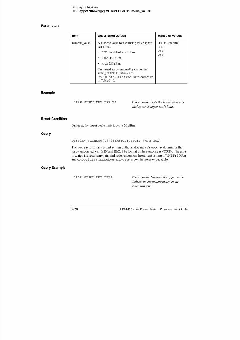
8/9/2019 E4416 Programming Guide
http://slidepdf.com/reader/full/e4416-programming-guide 274/615
5-20 EPM-P Series Power Meters Programming Guide
value associated with MIN and MAX. The format of the response is <NR3>. The units
in which the results are returned is dependent on the current setting of UNIT:POWer
and CALCulate:RELative:STATe as shown in the previous table.
Query Example
DISP:WIND2:MET:UPP? This command queries the upper scale
limit set on the analog meter in thelower window.
DISPlay Subsystem
DISPlay[:WINDow[1]|2][:NUMeric[1]|2]:RESolution <numeric_value>
DISPlay[:WINDow[1]|2][:NUMeric[1]|2]:RESolution <numeric_value>
This command sets the resolution of the measurement result in the specified window.
Syntax
Parameters
Example
Item Description/Default Range of Values
numeric_value A numeric value for the window resolution:
• DEF: 3
• MIN: 1
• MAX: 4
1 to 4
DEF
MIN
MAX
DISP:WIND2:RES 4 This command sets the lower window’s
resolution to four significant digits if
:RES Space
?
numeric_value
DEF
MIN
MAX
MIN
MAX
Space
:NUM:WIND 1
2
DISP 1
2

8/9/2019 E4416 Programming Guide
http://slidepdf.com/reader/full/e4416-programming-guide 275/615
EPM-P Series Power Meters Programming Guide 5-21
Reset Condition
On reset, the resolution is set to 3.
Query
DISPlay[:WINDow[1]|2]:RESolution? [MIN|MAX]
the measurement result is linear, or to
0.001 if the measurement result is
logarithmic.
DISPlay Subsystem
DISPlay[:WINDow[1]|2][:NUMeric[1]|2]:RESolution <numeric_value>
The query returns the current setting of the window’s resolution or the valueassociated with MIN and MAX. The format of the response is <NR1>.
Query Example
DISP:RES? This command queries the resolution
setting of the upper window.

8/9/2019 E4416 Programming Guide
http://slidepdf.com/reader/full/e4416-programming-guide 276/615
5-22 EPM-P Series Power Meters Programming Guide
DISPlay Subsystem
DISPlay[:WINDow[1]|2]:SELect[1]|2
DISPlay[:WINDow[1]|2]:SELect[1]|2
This command is used to select a specific measurement within a specific window.
If the second numeric value is not sent, the upper measurement of the relevant
window is selected. This command is used to specify which measurement will be
used for the analog, trace, or single numeric display.
Syntax
Example
Reset Condition
On reset, the upper window upper measurement is selected.
Query
DISPlay[:WINDow[1]|2]:SELect[1]|2?
The query enters a 1 or 0 into the output buffer indicating whether the window
specified is currently selected.
DISP:WIND2:SEL1 This command selects the upper
measurement in the lower window.
:SEL 1
2
?
:WIND 1
2
DISP

8/9/2019 E4416 Programming Guide
http://slidepdf.com/reader/full/e4416-programming-guide 277/615
EPM-P Series Power Meters Programming Guide 5-23
• 1 is returned if the specified window is selected.
• 0 is returned if the specified window is not selected.
Query Example
DISP:SEL1? This command queries whether or not
the upper measurement in the upper
window is selected.
DISPlay Subsystem
DISPlay[:WINDow[1]|2][:STATe] <boolean>
DISPlay[:WINDow[1]|2][:STATe] <boolean>
This command enables/disables the upper or lower window ( WINDow1 and
WINDow2 respectively) so that the display shows a single window only. The
displayed window is presented in expanded format, showing a single measurement
only: either the single measurement that was shown on the window, or the currently
selected measurement, if two measurements had been shown.
Syntax
Examples
DISP:WIND2:STAT OFF This command disables the lower
window. The upper window in shown in
expanded format, displaying its
currently selected measurement.
DISP:WIND2:STAT 1 This command enables the lower
window so that a dual window display
is once more provided.
:STAT 0|OFF
1|ON
Space
?
:WIND 1
2
DISP

8/9/2019 E4416 Programming Guide
http://slidepdf.com/reader/full/e4416-programming-guide 278/615
5-24 EPM-P Series Power Meters Programming Guide
Reset Condition
On reset, both windows are enabled.
Query
DISPlay[:WINDow[1]|2]:STATe?
The query enters a 1 or 0 into the output buffer indicating the state of the selected
window.
• 1 is returned if the window is enabled.
DISPlay Subsystem
DISPlay[:WINDow[1]|2][:STATe] <boolean>
• 0 is returned if the window is disabled.
Query ExampleQuery Example
DISP:WIND2:STAT? This command queries whether or not
the lower window is displayed.

8/9/2019 E4416 Programming Guide
http://slidepdf.com/reader/full/e4416-programming-guide 279/615
EPM-P Series Power Meters Programming Guide 5-25
DISPlay Subsystem
DISPlay[:WINDow[1]|2]:TRACe:FEED <character_data>
DISPlay[:WINDow[1]|2]:TRACe:FEED <character_data>
This command selects which channel’s trace is displayed in the specified window.
Syntax
Parameters
Example
Item Description/Default Range of Values
character_data Identifies which channel’s trace is displayed.
• SENS1: channel A.
• SENS2: channel B.
“SENS1”
“SENS2”
DISP:WIND2:TRAC:FEED“SENS1”
This command selects channel A’s trace
to be displayed in the lower window.
:WIND 1
2
:TRAC Space character_dataDISP :FEED

8/9/2019 E4416 Programming Guide
http://slidepdf.com/reader/full/e4416-programming-guide 280/615
5-26 EPM-P Series Power Meters Programming Guide
Reset Condition
On reset, the value is set to:
• Upper window: SENS1.
• Lower window (dual channel only): SENS2.
Query
DISPlay:[WINDow[1]|2]:TRACe:FEED?
DISPlay Subsystem
DISPlay[:WINDow[1]|2]:TRACe:FEED <character_data>
The query returns the channel of the trace currently displayed in the specifiedwindow.
Query Example
DISP:WIND2:TRAC:FEED? This command queries the channel of
the trace currently displayed in the
lower window.

8/9/2019 E4416 Programming Guide
http://slidepdf.com/reader/full/e4416-programming-guide 281/615
EPM-P Series Power Meters Programming Guide 5-27
DISPlay Subsystem
DISPlay[:WINDow[1]|2]:TRACe:LOWer <numeric_value>
DISPlay[:WINDow[1]|2]:TRACe:LOWer <numeric_value>
This command sets the trace window lower scale limit.
Note This command is included for compatibility purposes only. It has the same
purpose as
SENSe[1]|2:TRACe:LIMit:LOWer <numeric_value>
which should be used in preference.
The units used are dependent on the current setting of SENS:TRAC:UNIT as shownin the following table:
Table 0-11: Measurement Units
Syntax
Units:
SENS:TRAC:UNIT
Units:
DISPlay[:WINDow[1]|2]:TRACe:LOWer
dBm dBm
W W
:WIND 1
2
:TRAC Space
?
numeric_value
DEF
MIN
MAX
MINSpace
DISP :LOW

8/9/2019 E4416 Programming Guide
http://slidepdf.com/reader/full/e4416-programming-guide 282/615
5-28 EPM-P Series Power Meters Programming Guide
MAX
DISPlay Subsystem
DISPlay[:WINDow[1]|2]:TRACe:LOWer <numeric_value>
Parameters
Example
Reset Condition
On reset, the value is set to -50 dBm.
Query
DISPlay:[WINDow[1]|2]:TRACe:UPPer [MIN|MAX]
The query returns the current setting of the trace window lower scale limit or the
value associated with MIN or MAX. The format of the response is <NR3>.
Query Example
Item Description/Default Range of Values
numeric_value A numeric value for the trace window lower
scale limit.
• DEF: the default is 20 dBm
• MIN: -150 dBm
• MAX: 230 dBm
Units used are resolved to 1 dBm
-150 to 230 dBm
DEF
MIN
MAX
DISP:WIND2:TRAC:LOW 10 This command sets the trace window
lower scale limit to
10 dBm

8/9/2019 E4416 Programming Guide
http://slidepdf.com/reader/full/e4416-programming-guide 283/615
EPM-P Series Power Meters Programming Guide 5-29
DISP:WIND2:TRAC:LOW? This command queries the trace
window lower scale limit of the lower
window
DISPlay Subsystem
DISPlay[:WINDow[1]|2]:TRACe:UPPer <numeric_value>
DISPlay[:WINDow[1]|2]:TRACe:UPPer <numeric_value>
This command sets the trace window upper scale limit.
Note This command is included for compatibility purposes only. It has the same
purpose as
SENSe[1]|2:TRACe:LIMit:UPPer <numeric_value>
which should be used in preference.
The units used are dependent on the current setting of SENS:TRAC:UNIT as shownin the following table:
Table 0-12: Measurement Units
Syntax
Units:
SENS:TRAC:UNIT
Units:
DISPlay[:WINDow[1]|2]:TRACe:UPPer
dBm dBm
W W
:WIND 1
2
:TRAC Space
?
numeric_value
DEF
MIN
MAX
MINSpace
DISP :UPP

8/9/2019 E4416 Programming Guide
http://slidepdf.com/reader/full/e4416-programming-guide 284/615
5-30 EPM-P Series Power Meters Programming Guide
MAX
DISPlay Subsystem
DISPlay[:WINDow[1]|2]:TRACe:UPPer <numeric_value>
Parameters
Example
Reset Condition
On reset, the value is set to 20 dBm.
Query
DISPlay:[WINDow[1]|2]:TRACe:UPPer [MIN|MAX]
The query returns the current setting of the trace window upper scale limit or the
value associated with MIN or MAX. The format of the response is <NR3>.
Query Example
Item Description/Default Range of Values
numeric_value A numeric value for the trace window upper
scale limit.
• DEF: the default is 20 dBm
• MIN: -150 dBm
• MAX: 230 dBm
Units used are resolved to 1 dBm
-150 to 230 dBm
DEF
MIN
MAX
DISP:WIND2:TRAC:UPP 100 This command sets the trace window
upper scale limit to
100 dBm

8/9/2019 E4416 Programming Guide
http://slidepdf.com/reader/full/e4416-programming-guide 285/615
EPM-P Series Power Meters Programming Guide 5-31
DISP:WIND2:TRAC:UPP? This command queries the trace
window upper scale limit of the lower
window
DISPlay Subsystem
DISPlay[:WINDow[1]|2]:TRACe:UPPer <numeric_value>
THIS PAGE HAS BEEN INTENTIONALLY LEFT BLANK.

8/9/2019 E4416 Programming Guide
http://slidepdf.com/reader/full/e4416-programming-guide 286/615
5-32 EPM-P Series Power Meters Programming Guide
6
FORMat Subsystem

8/9/2019 E4416 Programming Guide
http://slidepdf.com/reader/full/e4416-programming-guide 287/615
FORMat Subsystem
FORMat Subsystem
FORMat Subsystem
The FORMat subsystem sets a data format for transferring numeric information. This
data format is used only for response data by commands that are affected by the
FORMat subsystem.
The queries affected are:
• FETCh?
• READ?
• MEASure?
For the E4417A power meter the same FORMat is used on both channels.
Keyword Parameter Form Notes Page
FORMat[:READings]
:BORDer <character_data> page 6-3
[:DATA] <character_data> page 6-4

8/9/2019 E4416 Programming Guide
http://slidepdf.com/reader/full/e4416-programming-guide 288/615
6-2 EPM-P Series Power Meters Programming Guide
FORMat Subsystem
FORMat[:READings]:BORDer <character_data>
FORMat[:READings]:BORDer <character_data>
This command controls whether the binary data is transferred in normal or swapped
Byte ORDer. It is only used when FORMat[:READings][:DATA] is set to REAL.
Syntax
Parameters
Example
Reset Condition
On reset, this value is set to NORMal.
Query
FORMat[:READings]:BORDer?
Item Description/Default Range of Values
character_data Byte order of binary data transfer:
• NORMal
• SWAPped
NORMal
SWAPped
FORM:BORD SWAP This command sets the byte order to
swapped.
FORM :READ :BORD Space
?
character_data

8/9/2019 E4416 Programming Guide
http://slidepdf.com/reader/full/e4416-programming-guide 289/615
EPM-P Series Power Meters Programming Guide 6-3
The query returns the current setting of the byte order. The format of the response is
NORMal or SWAPped.
Query Example
FORM:BORD? This command queries the current byte
order setting.
FORMat Subsystem
FORMat[:READings][:DATA] <character_data>
FORMat[:READings][:DATA] <character_data>
This command sets the data format for transferring numeric information to either
ASCii or REAL:
• When the format type is ASCii, numeric data is output as ASCII bytes in the
<NR3> format.
• When the format type is REAL, numeric data is output as IEEE 754 64 bit floating
point numbers in a definite length block. The result is an 8 byte block per number.
Each complete block is terminated by a line feed character.
For the E4417A power meter the same FORMat is used on both channels.
Note FORMat data formatting is not affected by TRACe subsystem data
formatting.
Syntax
Parameters
Item Description/Default Range of Values
character_data Data format for transferring data:
• ASCii
• REAL
ASCii
REAL
FORM :READ :DATA Space
?
character_data

8/9/2019 E4416 Programming Guide
http://slidepdf.com/reader/full/e4416-programming-guide 290/615
6-4 EPM-P Series Power Meters Programming Guide
Example
Reset Condition
On reset, the format is set to ASCii.
FORM REAL This command sets the format to REAL .
FORMat Subsystem
FORMat[:READings][:DATA] <character_data>
Query
FORMat[:READings][:DATA]?
The query returns the current setting of format: either ASCii or REAL.
Query Example
FORM? This command queries the current
format setting.

8/9/2019 E4416 Programming Guide
http://slidepdf.com/reader/full/e4416-programming-guide 291/615
EPM-P Series Power Meters Programming Guide 6-5

8/9/2019 E4416 Programming Guide
http://slidepdf.com/reader/full/e4416-programming-guide 292/615
7
MEMory Subsystem

8/9/2019 E4416 Programming Guide
http://slidepdf.com/reader/full/e4416-programming-guide 293/615
MEMory Subsystem
MEMory Subsystem
MEMory Subsystem
The MEMory command subsystem is used to:
• Edit and review sensor calibration tables (8480 Series power sensors and
N8480 Series sensors with Option CFT only).
• Store sensor calibration tables (8480 Series power sensors and N8480 Series
sensors with Option CFT only).
• Edit and review sensor frequency dependent offset tables.
• Store sensor frequency dependent offset tables.
• Edit and review sensor save/recall registers.
Stored tables remain in the power meter’s memory during power down. The power
meter is capable of storing 20 sensor calibration tables and 10 frequency dependent
offset tables of 80 frequency points each.
Note The MEMory subsystem is not used for E-Series power sensors and N8480
Series power sensors (excluding Option CFT) calibration tables which are
automatically downloaded to the power meter and cannot be reviewed or
edited.
Keyword Parameter Form Notes Page
MEMory:CATalog
[:ALL]? [query only] page 7-5
:STATe? [query only] page 7-7
:TABLe? [query only] page 7-8
:CLEar[:NAME] <character_data> [no query],
[non-SCPI]}
page 7-11
:TABLe [no query] page 7-12
:FREE[:ALL]? [query only] page 7-14

8/9/2019 E4416 Programming Guide
http://slidepdf.com/reader/full/e4416-programming-guide 294/615
7-2 EPM-P Series Power Meters Programming Guide
[ ] [q y y] p g
:STATe? [query only] page 7-15
:TABLe? [query only] page 7-16
:NSTates? [query only] page 7-17
:STATe:CATalog? [query only] page 7-19
:DEFine <character_data> [,<numeric_value>] [non-SCPI] page 7-20
:TABLe:FREQuency <numeric_value>
[,<numeric_value>] page 7-22
:POINts? [query only] page 7-25
MEMory Subsystem
MEMory Subsystem
:GAIN[:MAGNitude] <numeric_value>
[,<numeric_value>][non-SCPI] page 7-26
:POINts? [query only],
[non-SCPI]
page 7-28
:MOVE <character_data>, <character_data>
[no query],
[non-SCPI]
page 7-29
:SELect <character_data> [no query],
[non-SCPI]
page 7-30
Keyword Parameter Form Notes Page

8/9/2019 E4416 Programming Guide
http://slidepdf.com/reader/full/e4416-programming-guide 295/615
EPM-P Series Power Meters Programming Guide 7-3
MEMory Subsystem
MEMory:CATalog Commands
MEMory:CATalog Commands
These commands are used to query information on the current contents of a power
meter’s:
• Sensor calibration tables (8480 Series power sensors and N8480 Series
sensors with Option CFT only).
• Frequency dependent offset tables.
• Save/recall registers.
The following commands are detailed in this section:
MEMory:CATalog[:ALL]?MEMory:CATalog:STATe?MEMory:CATalog:TABLe?

8/9/2019 E4416 Programming Guide
http://slidepdf.com/reader/full/e4416-programming-guide 296/615
7-4 EPM-P Series Power Meters Programming Guide
MEMory Subsystem
MEMory:CATalog[:ALL]?
MEMory:CATalog[:ALL]?
This command lists stored sensor calibration tables (8480 Series power sensors and
N8480 Series sensors with Option CFT only), frequency dependent offset tables and
save/recall registers.
The power meter returns the data in the form of two numeric parameters and as many
strings as there are stored tables and save/recall registers:
<numeric_value>,<numeric_value>{,<string>}
• The first numeric parameter indicates the amount of memory, in bytes, usedfor the storage of tables and registers.
• The second numeric parameter indicates the memory, in bytes, available for
the storage of tables and registers.
• Each string parameter returned indicates the name, type and size of a stored
table or save/recall register:
■ <string>,<type>,<size>
◆ <string> indicates the name of the table or save/recall register.
◆
<type> indicates TABL for sensor calibration and frequencydependent offset tables, or STAT for a save/recall register.
◆ <size> indicates the size of the table or save/recall register in bytes.
A sample of a response may look like the following:
1178,26230,"DEFAULT,TABL,14","HP8481A,TABL,116", "HP8482A,TABL,74",..........."State0,STAT,1619", "State1,STAT,1619","State2,STAT,1619" ...........
Note Predefined sensor calibration table is not applicable for N8480 Series powersensors with Option CFT. Therefore you are required to create a new sensor
calibration table for the sensors when a sensor calibration table is needed.

8/9/2019 E4416 Programming Guide
http://slidepdf.com/reader/full/e4416-programming-guide 297/615
EPM-P Series Power Meters Programming Guide 7-5
The power meter is shipped with a set of predefined sensor calibration tables. The
data in these sensor calibration tables is based on statistical averages for a range of
MEMory Subsystem
MEMory:CATalog[:ALL]?
Agilent Technologies power sensors. These tables can be altered. The predefined data
is listed in your User’s Guide. These power sensors are:
There are also ten sensor calibration tables named CUSTOM_0 through CUSTOM_9
and ten frequency dependent offset tables named CUSTOM _A through CUSTOM _J
which do not contain any data when the power meter is shipped from the factory.
Syntax
Example
Table Power Sensor Table Name
0 None DEFAULT1
1. Default is a sensor calibration table in which the reference calibration
factor and calibration factors are 100%. This sensor calibration table can be
used during the performance testing of the power meter.
1 8481A HP8481A
2 8482A, 8482B, 8482H HP8482A
3 8483A HP8483A
4 8481D HP8481D
5 8485A HP8485A
6 R8486A R8486A
7 Q8486A Q8486A
8 R8486D R8486D
9 8487A HP8487A
MEM CAT? This command queries the list of tables
MEM :CAT :ALL ?
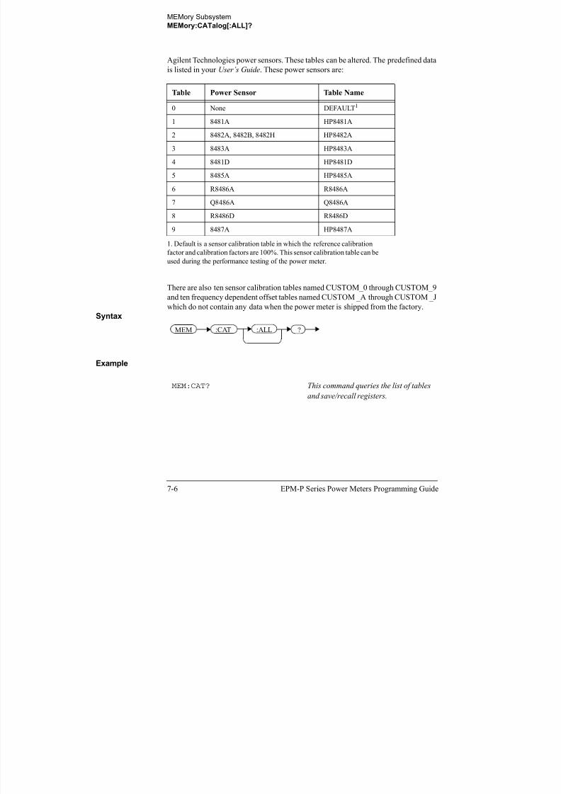
8/9/2019 E4416 Programming Guide
http://slidepdf.com/reader/full/e4416-programming-guide 298/615
7-6 EPM-P Series Power Meters Programming Guide
MEM:CAT? This command queries the list of tables
and save/recall registers.
MEMory Subsystem
MEMory:CATalog:STATe?
MEMory:CATalog:STATe?
This command is used to list the save/recall registers.
The power meter returns the data in the form of two numeric parameters and as many
strings as there are save/recall registers.
<numeric_value>,<numeric_value>{,<string>}
• The first numeric parameter indicates the amount of memory, in bytes, used
for the storage of registers.
• The second parameter indicates the memory, in bytes, available for thestorage of registers.
• Each string parameter returned indicates the name, type and size of a
save/recall register:
■ <string>,<type>,<size>
◆ <string> indicates the name of the save/recall register.
◆ <type> indicates STAT for save/recall register.
◆ <size> indicates the size of the save/recall register in bytes.
For example, a sample of a response may look like:
0,16190,"State0,STAT,0","State1,STAT,0" .........
Syntax
Example
MEM:CAT:STAT? This command queries the list of
save/recall registers.
MEM :CAT :STAT ?

8/9/2019 E4416 Programming Guide
http://slidepdf.com/reader/full/e4416-programming-guide 299/615
EPM-P Series Power Meters Programming Guide 7-7
MEMory Subsystem
MEMory:CATalog:TABLe?
MEMory:CATalog:TABLe?
This command is used to list the stored sensor calibration (8480 Series power sensors
and N8480 Series sensors with Option CFT only) and frequency dependent offset
tables.
The power meter returns the data in the form of two numeric parameters and as many
strings as there are stored tables.
<numeric_value>,<numeric_value>{,<string>}
• The first numeric parameter indicates the amount of memory, in bytes, usedfor the storage of tables.
• The second parameter indicates the memory, in bytes, available for the
storage of tables.
• Each string parameter returned indicates the name, type and size of a stored
table:
■ <string>,<type>,<size>
◆ <string> indicates the name of the table.
◆
<type> indicates TABL for a table.◆ <size> indicates the size of the table in bytes.
For example, a sample of a response may look like:
1178,10040,"DEFAULT,TABL,14","HP8481A,TABL,116", "HP8482A,TABL,74","HP8483A,TABL,62"...........
Note Predefined sensor calibration table is not applicable for N8480 Series power
sensors with Option CFT. Therefore you are required to create a new sensor
calibration table for the sensors when a sensor calibration table is needed.

8/9/2019 E4416 Programming Guide
http://slidepdf.com/reader/full/e4416-programming-guide 300/615
7-8 EPM-P Series Power Meters Programming Guide
MEMory Subsystem
MEMory:CATalog:TABLe?
The power meter is shipped with a set of predefined sensor calibration tables. The
data in these sensor calibration tables is based on statistical averages for a range ofAgilent power sensors. These tables can be altered. The predefined data is listed in
your User’s Guide. These power sensors are:
There are also ten sensor calibration tables named CUSTOM_0 through CUSTOM_9
and ten frequency dependent offset tables named CUSTOM_A through CUSTOM_J
which do not contain any data when the power meter is shipped from the factory.
Syntax
Table Power Sensor Table Name
0 None DEFAULT1
1. Default is a sensor calibration table in which the reference
calibration factor and calibration factors are 100%. This sensor
calibration table can be used during the performance testing of the
power meter.
1 8481A HP8481A
2 8482A, 8482B, 8482H HP8482A
3 8483A HP8483A
4 8481D HP8481D
5 8485A HP8485A
6 R8486A R8486A
7 Q8486A Q8486A
8 R8486D R8486D
9 8487A HP8487A
MEM :CAT :TABL ?

8/9/2019 E4416 Programming Guide
http://slidepdf.com/reader/full/e4416-programming-guide 301/615
EPM-P Series Power Meters Programming Guide 7-9
Example
MEM:CAT:TABL? This command queries the list of storedtables.
MEMory Subsystem
MEMory:CLEar Commands
MEMory:CLEar Commands
These commands are used to remove the contents stored in the sensor calibration
tables (8480 Series power sensors and N8480 Series sensors with Option CFT only),
frequency dependent offset tables and save/recall registers. This subsystem removes
the data contents but does not affect the name of the associated table or save/recall
register.
The following commands are detailed in this section:
MEMory:CLEar:[NAME] <character_data>
MEMory:CLEar:TABLe
Note The contents cleared using these commands are non-recoverable.

8/9/2019 E4416 Programming Guide
http://slidepdf.com/reader/full/e4416-programming-guide 302/615
7-10 EPM-P Series Power Meters Programming Guide
MEMory Subsystem
MEMory:CLEar[:NAME] <character_data>
MEMory:CLEar[:NAME] <character_data>
This command clears the contents of a specified sensor calibration table (8480 Series
power sensors and N8480 Series sensors with Option CFT only), frequency
dependent offset table, or save/recall register.
Although the table remains, a MEMory:TABLe:FREQuency|GAIN:POINts?
query returns a 0 as there are no contents in the table.
For sensor calibration tables and frequency dependent offset tables, this command is
an alternative form of the MEMory:CLEar:TABLE command, the only difference
being the method in which the table is selected.
Note The contents cleared using this command are non-recoverable.
Syntax
Parameters
Example
Item Description/Default Range of Values
character_data Contains an existing table name or save/recall
register.
Any existing table
name or save/recall
register.
MEM:CLE "HP8485A" This command clears the contents of
sensor calibration table HP 8485A
MEM :CLE :NAME Space character_data

8/9/2019 E4416 Programming Guide
http://slidepdf.com/reader/full/e4416-programming-guide 303/615
EPM-P Series Power Meters Programming Guide 7-11
Error Messages
If the table or save/recall register name does not exist, error -224, “Illegal parametervalue” occurs.
MEMory Subsystem
MEMory:CLEar:TABle
MEMory:CLEar:TABle
This command is used to clear the contents of the table currently selected using
MEMory:TABLe:SELect. Although the table remains, a
MEMory:TABLe:FREQuency|GAIN:POINts? query returns a 0 as there are no
contents in the table.
This command is an alternative form of the MEMory:CLEar[:NAME] command,
the only difference being the method in which the table is selected.
Note The contents cleared using this command are non-recoverable.
Syntax
Example
Error Message
If no table is selected, error -221, “Settings conflict” occurs.
MEM:CLE:TABL This command clears the contents of
the currently selected table.
MEM :CLE :TABL

8/9/2019 E4416 Programming Guide
http://slidepdf.com/reader/full/e4416-programming-guide 304/615
7-12 EPM-P Series Power Meters Programming Guide
MEMory Subsystem
The MEMory:FREE Commands
The MEMory:FREE Commands
These commands are used to return information on the amount of free memory space
available for sensor calibration tables 8480 Series power sensors and N8480 Series
sensors with Option CFT only), frequency dependent offset tables, and save/recall
registers.
The following commands are described in this section:
MEMory:FREE[:ALL]?MEMory:FREE:STATe?
MEMory:FREE:TABLe?

8/9/2019 E4416 Programming Guide
http://slidepdf.com/reader/full/e4416-programming-guide 305/615
EPM-P Series Power Meters Programming Guide 7-13
MEMory Subsystem
MEMory:FREE[:ALL]?
MEMory:FREE[:ALL]?
This query returns the amount of memory free for sensor calibration tables (8480
Series power sensors and N8480 Series sensors with Option CFT only), frequency
dependent offset tables, and save/recall registers. The format of the response is:
<bytes_available>,<bytes_in_use>
Syntax
Example
MEM:FREE? This command queries the amount of
free memory in total.
MEM :FREE :ALL ?

8/9/2019 E4416 Programming Guide
http://slidepdf.com/reader/full/e4416-programming-guide 306/615
7-14 EPM-P Series Power Meters Programming Guide
MEMory Subsystem
MEMory:FREE:STATe?
MEMory:FREE:STATe?
This query returns the amount of memory free for save/recall registers. The format of
the response is:
<bytes_available>,<bytes_in_use>
Syntax
Example
MEM:FREE:STAT? This command queries the amount of
free memory for save/recall registers.
MEM :FREE :STAT ?

8/9/2019 E4416 Programming Guide
http://slidepdf.com/reader/full/e4416-programming-guide 307/615
EPM-P Series Power Meters Programming Guide 7-15
MEMory Subsystem
MEMory:FREE:TABLe?
MEMory:FREE:TABLe?
This query returns the amount of memory free for sensor calibration tables (8480
Series power sensors and N8480 Series sensors with Option CFT only) and frequency
dependent offset tables. The format of the response is:
<bytes_available>,<bytes_in_use>
Syntax
Example
MEM:FREE:TABL? This command queries the amount of
free memory for tables.
MEM :FREE :TABL ?

8/9/2019 E4416 Programming Guide
http://slidepdf.com/reader/full/e4416-programming-guide 308/615
7-16 EPM-P Series Power Meters Programming Guide
MEMory Subsystem
MEMory:NSTates?
MEMory:NSTates?This query returns the number of registers that are available for save/recall. As there
are ten registers this query always returns ten.
Syntax
Example
MEM:NST? This command queries the number of
registers available for save/recall.
MEM :NST ?

8/9/2019 E4416 Programming Guide
http://slidepdf.com/reader/full/e4416-programming-guide 309/615
EPM-P Series Power Meters Programming Guide 7-17
MEMory Subsystem
The MEMory:STATe Commands
The MEMory:STATe CommandsThese commands are used to query and define register names.
The following commands are described in this section:
MEMory:STATe:CATalog?MEMory:STATe:DEFine

8/9/2019 E4416 Programming Guide
http://slidepdf.com/reader/full/e4416-programming-guide 310/615
7-18 EPM-P Series Power Meters Programming Guide
MEMory Subsystem
MEMory:STATe:CATalog?
MEMory:STATe:CATalog?This query returns a list of the save/recall register names in ascending order of
register number. The format of the response is:
<string>,<string>,.....,<string>
Syntax
Example
MEM:STAT:CAT? This command queries the register
names.
MEM :STAT :CAT ?

8/9/2019 E4416 Programming Guide
http://slidepdf.com/reader/full/e4416-programming-guide 311/615
EPM-P Series Power Meters Programming Guide 7-19
MEMory Subsystem
MEMory:STATe:DEFine <character_data>,<numeric_value>
MEMory:STATe:DEFine <character_data>,<numeric_value>This command is used to associate a name with a save/recall register number.
Syntax
Parameters
Example
Query
MEMory:STATe:DEFine? <string>
The query returns the register number for the given register name.
Query Example
Error Messages
Item Description/Default Range of Values
character_data Details the register name. A maximum of 12
characters can be used.
A to Z (uppercase)
a to z (lowercase)
0 - 9
_ (underscore)
numeric_value A numeric value (<NRf>) for the register
number.
0 to 9
MEM:STAT:DEF "SETUP1",4 This command names register 4
SETUP1.
MEM:STAT:DEF? "SETUP1" This command queries the register
number of SETUP1.
MEM :STAT numeric_value:DEF ,Space
? Space
character_data
character_data

8/9/2019 E4416 Programming Guide
http://slidepdf.com/reader/full/e4416-programming-guide 312/615
7-20 EPM-P Series Power Meters Programming Guide
Error Messages
• If the register number is out of range, error -222, “Data out of range” occurs.
• If the name is invalid, error -224, “Illegal parameter value” occurs.• If a register or sensor calibration table with the same name already exists, error
-257, “File name error” occurs (command only).
MEMory Subsystem
MEMory:TABLe Commands
MEMory:TABLe CommandsThese commands are used to define a sensor calibration table (8480 Series power
sensors and N8480 Series sensors with Option CFT only) or a frequency dependent
offset table, and to write to and read data from it.
The following commands are described in this section:
MEMory:TABLe:FREQuency <numeric_value>{,<numeric_value>}MEMory:TABLe:FREQuency:POINts?MEMory:TABLe:GAIN[:MAGNitude]
<numeric_value>{,<numeric_value>}MEMory:TABLe:GAIN[:MAGNitude]:POINts?MEMory:TABLe:MOVE <character_data>,<character_data>MEMory:TABLe:SELect <character_data>

8/9/2019 E4416 Programming Guide
http://slidepdf.com/reader/full/e4416-programming-guide 313/615
EPM-P Series Power Meters Programming Guide 7-21
MEMory Subsystem
MEMory:TABLe:FREQuency <numeric_value>{,<numeric_value>}
MEMory:TABLe:FREQuency <numeric_value>{,<numeric_value>}This command is used to enter frequency data into the current selected table. Any
previous frequency list is cleared before the new frequencies are stored. The
frequencies must be entered in ascending order. Entries in the frequency lists
correspond as shown with entries in the calibration/offset factor lists. Note, that for
sensor calibration tables only, the first calibration factor entered using the
MEMory:TABLe:GAIN command is used as the reference calibration factor.
For sensor calibration tables (8480 Series power sensors and N8480 Series sensors
with Option CFT only), the number of frequency points must be one less than the
number of calibration factor points. This is verified when the sensor calibration table
is selected using SENSe:CORRection:CSET:SELect <string>.
Ensure that the frequency points you use cover the frequency range of the signals that
you want to measure. If you measure a signal with a frequency outside the frequency
range defined in the table, then the power meter uses the highest or lowest point in the
table to calculate the calibration factor/offset.
Depending on available memory, the power meter is capable of storing 20 sensor
calibration tables and 10 frequency dependent offset tables, each containing 80
points.
Syntax
Frequency Calibration Factor/Offset
- Reference Calibration Factor
(For Sensor Calibration Tables)
Frequency 1 Calibration Factor/Offset 1
Frequency 2 Calibration Factor/Offset 2
" "
Frequency 80 Calibration Factor/Offset 80

8/9/2019 E4416 Programming Guide
http://slidepdf.com/reader/full/e4416-programming-guide 314/615
7-22 EPM-P Series Power Meters Programming Guide
MEM :TABL :FREQ numeric_valueSpace
,
?
MEMory Subsystem
MEMory:TABLe:FREQuency <numeric_value>{,<numeric_value>}
Parameters
Example
Query
MEMory:TABLe:FREQuency?
The query returns a list of frequency points for the table currently selected. The
frequencies are returned in Hz.
Query Example
Item Description/Default Range of Values
numeric_value A numeric value for the frequency. The
default units are Hz.1 kHz to 999.9 GHz1, 2
1. The following measurement units can be used:
•Hz
•kHz (103)
•MHz (106)
•GHz (109)2. All frequencies are truncated to a multiple of 1 kHz.
MEM:TABL:FREQ 200kHz,600kHz This command enters frequencies
of 200 kHz and 600 kHz into the
currently selected table.
MEM:TABL:FREQ? This command queries the frequency
points in the currently selected table.

8/9/2019 E4416 Programming Guide
http://slidepdf.com/reader/full/e4416-programming-guide 315/615
EPM-P Series Power Meters Programming Guide 7-23
MEMory Subsystem
MEMory:TABLe:FREQuency <numeric_value>{,<numeric_value>}
Error Messages
• If more than 80 frequencies are in the list, error -108, “Parameter not allowed”occurs.
• If the frequencies are not entered in ascending order, error -220, “Parameter
error;Frequency list must be in ascending order” occurs.
• If a table has not been specified using the MEMory:TABLe:SELect command,
the data cannot be entered into the table and error -221, “Settings conflict”
occurs.
• If a frequency is sent which is outside of the allowed frequency range, error -222,
“Data out of range” occurs.

8/9/2019 E4416 Programming Guide
http://slidepdf.com/reader/full/e4416-programming-guide 316/615
7-24 EPM-P Series Power Meters Programming Guide
MEMory Subsystem
MEMory:TABLe:FREQuency:POINts?
MEMory:TABLe:FREQuency:POINts?
This query returns the number of frequency points for the table currently selected.
The response format is <NRf>. If no frequency values have been set, this command
returns 0. If no table is selected, this command returns NAN.
Syntax
Example
MEM:TABL:FREQ:POIN? This command queries the number of
frequency points in the current table.
MEM :TABL :POIN ?:FREQ

8/9/2019 E4416 Programming Guide
http://slidepdf.com/reader/full/e4416-programming-guide 317/615
EPM-P Series Power Meters Programming Guide 7-25
MEMory Subsystem
MEMory:TABLe:GAIN[:MAGNitude] <numeric_value>{,<numeric_value>}
MEMory:TABLe:GAIN[:MAGNitude] <numeric_value>{,<numeric_value>}
This command is used to enter calibration factors into the sensor calibration table
(8480 Series power sensors and N8480 Series sensors with Option CFT only) or
offsets into the frequency dependent offset table, currently selected using
MEMory:TABLe:SELect. Any previous calibration factor list, or offset list is
cleared before the new calibration factors/offsets are stored.
A maximum of 81 parameters for sensor calibration tables and 80 parameters for
frequency dependent offset tables can be sent with this command. For sensor
calibration tables only, the first parameter is the reference calibration factor, each
subsequent parameter is a calibration factor point in the sensor calibration table.
Entries in the frequency lists correspond as shown with entries in the
calibration/offset factor lists.
For sensor calibration tables the number of frequency points must be one less than the
number of calibration factor data points. This is verified when the sensor calibration
table is selected using SENSe:CORRection:CSET1:SELect <string>.
Syntax
Calibration Factor/Offset Frequency
Reference Calibration Factor
(Sensor Cal Table Only)
-
Calibration Factor/Offset 1 Frequency 1
" "
Calibration Factor/Offset 80 Frequency 80
MEM :TABL :GAIN :MAGN numeric_valueSpace
,
?

8/9/2019 E4416 Programming Guide
http://slidepdf.com/reader/full/e4416-programming-guide 318/615
7-26 EPM-P Series Power Meters Programming Guide
MEMory Subsystem
MEMory:TABLe:GAIN[:MAGNitude] <numeric_value>{,<numeric_value>}
Parameters
Example
Query
MEMory:TABLe:GAIN[:MAGNitude]?
The query returns a list of calibration factor/offset points for the currently selectedtable.
Query Example
Error Messages• If more than 81 calibration factors for sensor calibration tables, or 80 offsets for
frequency dependent offset tables are in the list, error -108, “Parameter not
allowed” occurs.
• If a table is not specified using the MEMory:TABLe:SELect command, the
data cannot be entered and error -221, “Settings conflict” occurs.
• If any of the calibration/offset factors are outside of the allowed range, error
Item Description/Default Range of Values
numeric_value A numeric value for the calibration/ offset
factors. The units are PCT.
1.0 to 150.0
MEM:TABL:SEL "Sensor_1"MEM:TABL:GAIN 97,99.5,97.4 This command enters a referencecalibration factor of 97% and
calibration factors of 99.5% and 97.4%
into the sensor calibration table.
MEM:TABL:GAIN? This command queries the calibration
factor/offset in the current table.
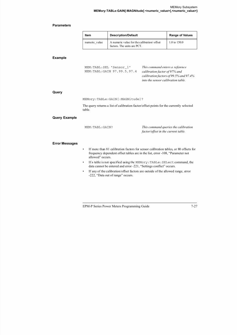
8/9/2019 E4416 Programming Guide
http://slidepdf.com/reader/full/e4416-programming-guide 319/615
EPM-P Series Power Meters Programming Guide 7-27
-222, “Data out of range” occurs.
MEMory Subsystem
MEMory:TABLe:GAIN[:MAGNitude]:POINts?
MEMory:TABLe:GAIN[:MAGNitude]:POINts?
This query is used to return the number of calibration factor/offset points for the
currently selected table. If the currently selected table is a sensor calibration table
(8480 Series power sensors and N8480 Series sensors with Option CFT only), the
reference calibration factor will be included
If no values have been set, 0 is returned. If no table is selected, NAN is returned.
Syntax
Example
MEM:TABL:GAIN:POIN? This command queries the number of
calibration factor/offset points in the
current table.
MEM :TABL :GAIN :MAGN :POIN ?

8/9/2019 E4416 Programming Guide
http://slidepdf.com/reader/full/e4416-programming-guide 320/615
7-28 EPM-P Series Power Meters Programming Guide
MEMory Subsystem
MEMory:TABLe:MOVE <character_data>,<character_data>
MEMory:TABLe:MOVE <character_data>,<character_data>
This command is used to rename a sensor calibration table (8480 Series power
sensors and N8480 Series sensors with Option CFT only) or a frequency dependent
offset table.
Syntax
Parameters
Example
Error Messages
• If either table name is invalid, error -224, “Illegal parameter value” occurs.
• If the first parameter does not match an existing table name, error -256, “File
name not found” occurs.
• If the second parameter matches an existing table name or save/recall register,
error -257, “File name error” occurs.
Item Description/Default Range of Values
character_data
1st parameter)
Contains the existing table name. existing table name
character_data(2n
d parameter)
Details the new table name. A maximum of
12 characters can be used.
A to Z (uppercase)
a to z (lowercase)
0 - 9
_ (underscore)
MEM:TABL:MOVE "tab1","tab1a" This command renames a table named
tab1 to tab1a.
MEM :TABL :MOVE ,Space character_data character_data

8/9/2019 E4416 Programming Guide
http://slidepdf.com/reader/full/e4416-programming-guide 321/615
EPM-P Series Power Meters Programming Guide 7-29
MEMory Subsystem
MEMory:TABLe:SELect <character_data>
MEMory:TABLe:SELect <character_data>
This command is used to activate either a sensor calibration table (8480 Series power
sensors and N8480 Series sensors with Option CFT only), or a frequency dependent
offset table. A table must be activated before any operation can be performed on it.
Syntax
Parameters
Example
Query
MEMory:TABLe:SELect?
The query returns the name of the currently selected table.
Item Description/Default Range of Values
character_data Details the table name. A maximum of 12
characters can be used.
A to Z (uppercase)
a to z (lowercase)
0 - 9
_ (underscore)
MEM:TABL:SEL "Sensor1" This command selects a sensor
calibration table named “Sensor1”.
MEM :TABL :SEL
?
Space character_data

8/9/2019 E4416 Programming Guide
http://slidepdf.com/reader/full/e4416-programming-guide 322/615
7-30 EPM-P Series Power Meters Programming Guide
8
OUTput Subsystem

8/9/2019 E4416 Programming Guide
http://slidepdf.com/reader/full/e4416-programming-guide 323/615
OUTput Subsystem
OUTPut Subsystem
OUTPut Subsystem
The OUTPut command subsystem is used to switch on and off the POWER REF
output and control the rear panel TTL outputs. The TTL Outputs can be used to
determine when a predefined limit in either, or both, windows has been exceeded.
Keyword Parameter Form Notes Page
OUTPut:RECorder[1]|2
:FEED <data_handle> page 8-3
:LIMit:LOWer <numeric_value> page 8-5
:UPPer <numeric_value> page 8-7
:STATe <boolean> page 8-9
:ROSCillator[:STATe] <boolean> page 8-10
:TRIGger[:STATe] <boolean> page 8-11
:TTL[1]|2:ACTive HIGH|LOW page 8-12
:FEED <string> page 8-14
:STATe <boolean> page 8-16

8/9/2019 E4416 Programming Guide
http://slidepdf.com/reader/full/e4416-programming-guide 324/615
8-2 EPM-P Series Power Meters Programming Guide
OUTput Subsystem
OUTPut:RECorder[1]|2:FEED <data_handle>
OUTPut:RECorder[1]|2:FEED <data_handle>
This command specifies which measurement is sent to the recorder output specified
by the numeric value following RECorder. RECorder1 applies to both single and
dual channel power meters. RECorder2 applies to dual channel power meters only.
Syntax
Parameters
Example
Reset Condition
On reset, data_handle is set to its previous value.
Query
OUTPut:RECorder[1]|2:FEED?
The query command returns the current value of data handle
Item Description/Default Range of Values
data_handle The CALC block specifying the
measurement to be sent to the recorder
output.
“CALC1” or “CALC”
“CALC2”
“CALC3”“CALC4”
OUTP:REC2:FEED “CALC1” This command sends the CALC1
measurement to recorder output 2.
OUTP :FEED:REC Space
?
1
2
data_handle

8/9/2019 E4416 Programming Guide
http://slidepdf.com/reader/full/e4416-programming-guide 325/615
EPM-P Series Power Meters Programming Guide 8-3
The query command returns the current value of data_handle.
OUTput Subsystem
OUTPut:RECorder[1]|2:FEED <data_handle>
Query Example
OUTP:REC2:FEED? This command queries the value of
data_handle for recorder output 2.

8/9/2019 E4416 Programming Guide
http://slidepdf.com/reader/full/e4416-programming-guide 326/615
8-4 EPM-P Series Power Meters Programming Guide
OUTput Subsystem
OUTPut:RECorder[1]|2:LIMit:LOWer <numeric_value>
OUTPut:RECorder[1]|2:LIMit:LOWer <numeric_value>
This command sets the minimum scaling value for the specified recorder output. The
units used are dependent on the units currently set for the CALC block specified in
OUTPut:RECorder[1]|2:FEED <data_handle>.
Syntax
Parameters
Example
Reset Condition
On reset, the minimum scaling value is set to -150 dBm.
Query
OUTPut:RECorder[1]|2:LIMit:LOWer?
Item Description/Default Range of Values
numeric_value A numeric value for the minimum scaling
value. The units used—dBm, W or %—are
dependent on the units currently set for theCALC block specified in
OUTPut:RECorder[1]|2:FEED
<data_handle>.
-150 to +20 dBm
1 aW to 100 mW
0% to 100%
OUTP:REC:LIM:LOW -90 This command sets the minimum
scaling value to -90.
OUTP :LIM:REC Space
?
:LOW numeric_value1
2

8/9/2019 E4416 Programming Guide
http://slidepdf.com/reader/full/e4416-programming-guide 327/615
EPM-P Series Power Meters Programming Guide 8-5
OUTPut:RECorder[1]|2:LIMit:LOWer?
The query command returns the minimum scaling value.
OUTput Subsystem
OUTPut:RECorder[1]|2:LIMit:LOWer <numeric_value>
Query Example
OUTP:REC:LIM:LOW? This command returns the minimum
scaling value for the specified recorder
output.

8/9/2019 E4416 Programming Guide
http://slidepdf.com/reader/full/e4416-programming-guide 328/615
8-6 EPM-P Series Power Meters Programming Guide
OUTput Subsystem
OUTPut:RECorder[1]|2:LIMit:UPPer <numeric_value>
OUTPut:RECorder[1]|2:LIMit:UPPer <numeric_value>
This command sets the maximum scaling value for the specified recorder output. The
units used are dependent on the units currently set for the CALC block specified in
OUTPut:RECorder[1]|2:FEED <data_handle>.
Syntax
Parameters
Example
Reset Condition
On reset, the maximum scaling value is set to +20 dBm.
Query
OUTPut:RECorder[1]|2:LIMit:UPPer?
Item Description/Default Range of Values
numeric_value A numeric value for the maximum scaling
value. The units used—dBm, W or %—are
dependent on the units currently set for theCALC block specified in
OUTPut:RECorder[1]|2:FEED
<data_handle>.
-150 to +20 dBm
1 aW to 100 mW
0% to 100%
OUTP:REC:LIM:UPP 10 This command sets the maximum
scaling value to 10.
OUTP :LIM:REC Space
?
:UPP numeric_value1
2

8/9/2019 E4416 Programming Guide
http://slidepdf.com/reader/full/e4416-programming-guide 329/615
EPM-P Series Power Meters Programming Guide 8-7
|
The query command returns the maximum scaling value.
OUTput Subsystem
OUTPut:RECorder[1]|2:LIMit:UPPer <numeric_value>
Query Example
OUTP:REC:LIM:UPP? This command returns the maximum
scaling value for the specified recorder
output.

8/9/2019 E4416 Programming Guide
http://slidepdf.com/reader/full/e4416-programming-guide 330/615
8-8 EPM-P Series Power Meters Programming Guide
OUTput Subsystem
OUTPut:RECorder[1]|2:STATe <boolean>
OUTPut:RECorder[1]|2:STATe <boolean>
This command enables or disables the specified recorder output.
Syntax
Example
Reset Condition
On reset, the recorder output is OFF.
Query
OUTPut:RECorder[1]|2:STATe?
The query command enters a 1 or 0 into the output buffer indicating whether or not
the specified recorder is switched on.
• 1 is returned when the recorder output is switched ON.
• 0 is returned when the recorder output is switched OFF.
Query Example
OUTP:REC1:STAT 1 This command enables the specified
recorder output.
OUTP:REC2:STAT? This command queries the status of the
recorder output.
OUTP :STAT:REC 0|OFF
1|ON
Space
?
1
2

8/9/2019 E4416 Programming Guide
http://slidepdf.com/reader/full/e4416-programming-guide 331/615
EPM-P Series Power Meters Programming Guide 8-9
OUTput Subsystem
OUTPut:ROSCillator[:STATe] <boolean>
OUTPut:ROSCillator[:STATe] <boolean>
This command enables/disables the POWER REF output.
Syntax
Example
Reset Condition
On reset, the POWER REF output is disabled.
Query
OUTPut:ROSCillator[:STATe]?
The query command enters a 1 or 0 into the output buffer indicating whether or not
the POWER REF is enabled.
• 1 is returned when the POWER REF output is enabled.
• 0 is returned when the POWER REF output is disabled.
Query Example
OUTP:ROSC:STAT 1 This command enables the POWER
REF output.
OUTP:ROSC? This command queries the status of the
POWER REF output.
OUTP :STAT:ROSC 0|OFF
1|ON
Space
?
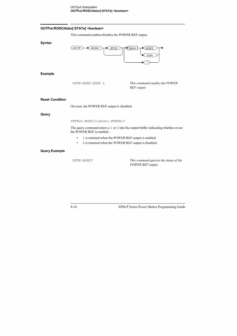
8/9/2019 E4416 Programming Guide
http://slidepdf.com/reader/full/e4416-programming-guide 332/615
8-10 EPM-P Series Power Meters Programming Guide
OUTput Subsystem
OUTPut:TRIGger[:STATe] <boolean>
OUTPut:TRIGger[:STATe] <boolean>
This command enables/disables the trigger output signal.
Syntax
Example
Reset Condition
On reset, the trigger output signal is disabled.
Query
OUTPut:TRIGger[:STATe]?
The query command enters a 1 or 0 into the output buffer indicating whether or not
the trigger output signal is enabled/disabled.
• 1 is returned when the trigger output signal is enabled.
• 0 is returned when the trigger output signal is disabled.
Query Example
OUTP:TRIG:STAT 1 This command enables the trigger
output signal.
OUTP:TRIG:STAT? This command queries the status of the
trigger output signal.
OUTP :STAT:TRIG 0|OFF
1|ON
Space
?

8/9/2019 E4416 Programming Guide
http://slidepdf.com/reader/full/e4416-programming-guide 333/615
EPM-P Series Power Meters Programming Guide 8-11
OUTput Subsystem
OUTPut:TTL[1]|2:ACTive HIGH|LOW
OUTPut:TTL[1]|2:ACTive HIGH|LOW
This command controls whether a window limits fail drives the rear panel TTL
Output HIGH or LOW. There are two TTL outputs:
• Output 1 (TTL1).
• Output 2 (TTL2).
Both can be connected to any of the CALC subsytems (that is the upper window
upper/lower measurement or the lower window upper/lower measurement) using
OUTput:TTL:FEED <string>.
Syntax
Example
Reset Condition
On reset, a window limits fail will drive the TTL Output low.
Query
OUTPut:TTL[1]|2:ACT?
The query command enters either HIGH or LOW into the output buffer indicating
which TTL state is active for a window limit fail.
• HIGH is returned if the TTL output is active high for a window limit fail.
• LOW is returned if the TTL output is active low for a window limit fail.
OUTP:TTL1:ACT HIGH This command sets TTL output 1 HIGH
whenever there is a limits fail in the
upper window.
OUTP 1 :ACT HIGH
LOW
Space
?
:TTL
2

8/9/2019 E4416 Programming Guide
http://slidepdf.com/reader/full/e4416-programming-guide 334/615
8-12 EPM-P Series Power Meters Programming Guide
OUTput Subsystem
OUTPut:TTL[1]|2:ACTive HIGH|LOW
Query Example
OUTP:TTL1:ACT? This command queries whether the TTL
Output for an upper window limit fail is
active high or low.

8/9/2019 E4416 Programming Guide
http://slidepdf.com/reader/full/e4416-programming-guide 335/615
EPM-P Series Power Meters Programming Guide 8-13
OUTput Subsystem
OUTPut:TTL[1]|2:FEED <string>
OUTPut:TTL[1]|2:FEED <string>
This command controls which limit test drives a given TTL output. There are two
TTL outputs:
• Output 1 (TTL1).
• Output 2 (TTL2).
Both can be connected to any of the CALC subsytems (that is the upper window
upper/lower measurement or the lower window upper/lower measurement) using
OUTput:TTL:FEED <string>.
Syntax
Parameters
TTL
[1|2] String Description
1 “CALC1|2|3|4:LIM:LOW” TTL Output 1 asserted indicates a lower limit
fail on the appropriate window/measurement.
“CALC1|2|3|4:LIM:UPP” TTL Output 1 asserted indicates an upper
limit fail on the appropriate
window/measurement.
“CALC1|2|3|4:LIM:LOW,
CALC1|2|3|4:LIM:UPP”1TTL Output 1 asserted indicates that either
the lower or upper limit failed on the
appropriate window/measurement.
2 “CALC1|2|3|4:LIM:LOW” TTL Output 2 asserted indicates a lower limit
fail on the appropriate window/measurement.
“CALC1|2|3|4:LIM:UPP” TTL Output 2 asserted indicates an upper
limit fail on the appropriate
window/measurement.
“CALC1|2|3|4:LIM:LOW, 1
TTL Output 2 asserted indicates that either
Space String
?
:FEEDOUTP 1:TTL
2

8/9/2019 E4416 Programming Guide
http://slidepdf.com/reader/full/e4416-programming-guide 336/615
8-14 EPM-P Series Power Meters Programming Guide
CALC1|2|3|4:LIM:UPP” the lower or upper limit failed on theappropriate window/measurement.
OUTput Subsystem
OUTPut:TTL[1]|2:FEED <string>
Example
Reset Condition
On reset, the TTL output will represent an upper limit fail.
Query
OUTPut:TTL[1|2]:FEED?
The query command returns one of the strings shown in the table above, indicating
whether the asserted state of the TTL Output represents a fail in the lower limit, upper
limit or either limit for the selected window/measurement.
Query Example
Note: Either single or double quotes may be used. However, quotes are mandatory.
All the above strings must be matched exactly - long forms and omission of the sub-op code are
not permissible.
1. The numeric value must be the same for both LOW and UP.
OUTP:TTL1:FEED “CALC1:LIM:UPP” This command asserts TTL
Output 1 whenever there is an
upper limit fail in the upper
window/upper measurement.
OUTP:TTL1:FEED? This command returns the string for
TTL Output 1.
TTL
[1|2]
String Description

8/9/2019 E4416 Programming Guide
http://slidepdf.com/reader/full/e4416-programming-guide 337/615
EPM-P Series Power Meters Programming Guide 8-15
OUTput Subsystem
OUTPut:TTL[1|2]:STATe <boolean>
OUTPut:TTL[1|2]:STATe <boolean>
This command is used to enable and disable the rear panel TTL Outputs.
There are two TTL outputs:
• Output 1 (TTL1).
• Output 2 (TTL2).
Both can be connected to any of the CALC subsytems (that is the upper window
upper/lower measurement or the lower window upper/lower measurement) using
OUTput:TTL:FEED <string>.
When enabled, the TTL Outputs can be used to determine when a predefined limit is
exceeded.
Syntax
Example
Reset Condition
On reset, the TTL outputs are disabled.
Query
OUTPut:TTL[1|2]:STATe?
The query command enters a 1 or 0 into the output buffer indicating whether or not
the TTL output is enabled.
• 1 is returned when the TTL output is enabled.
OUTP:TTL1:STAT 1 This command enables the rear panel
upper window TTL output.
OUTP 1
2
:STAT 0|OFF
1|ON
Space
?
:TTL

8/9/2019 E4416 Programming Guide
http://slidepdf.com/reader/full/e4416-programming-guide 338/615
8-16 EPM-P Series Power Meters Programming Guide
• 0 is returned when the TTL output is disabled.
OUTput Subsystem
OUTPut:TTL[1|2]:STATe <boolean>
Query Example
OUTP:TTL1:STAT? This command queries whether or not
the upper window TTL output is
enabled.

8/9/2019 E4416 Programming Guide
http://slidepdf.com/reader/full/e4416-programming-guide 339/615
EPM-P Series Power Meters Programming Guide 8-17
OUTput Subsystem
OUTPut:TTL[1|2]:STATe <boolean>
THIS PAGE HAS BEEN INTENTIONALLY LEFT BLANK.

8/9/2019 E4416 Programming Guide
http://slidepdf.com/reader/full/e4416-programming-guide 340/615
8-18 EPM-P Series Power Meters Programming Guide
9
SENSe Subsystem

8/9/2019 E4416 Programming Guide
http://slidepdf.com/reader/full/e4416-programming-guide 341/615
SENSe Subsystem
[SENSe] Subsystem
[SENSe] Subsystem
The SENSe command subsystem directly affects device specific settings used to
make measurements. The SENSe subsystem is optional since this is the primary
function of the power meter. The high level command CONFigure uses the SENSe
commands to prepare the power meter for making measurements. At a lower level
SENSe enables you to change the following parameters: RANGe, FREQuency,
LOSS, CFACator|GAIN1 (calibration factor), GAIN2 (channel offset), DCYCle
(duty cycle) and AVERage, without completely re-configuring the power meter.
The SENSe command subsystem also allows you to select the measurement speed, a
sensor calibration table, and a frequency dependent offset table.
The numeric suffix of the SENSe program mnemonic in the SENSe commands refers
to a channel, that is SENSe1 and SENSe2 represent channel A and channel B
respectively.
Note If you are using the single channel E4416A power meter the SENSe2 commands
are irrelevant and cause the error “Header suffix out of range.”

8/9/2019 E4416 Programming Guide
http://slidepdf.com/reader/full/e4416-programming-guide 342/615
9-2 EPM-P Series Power Meters Programming Guide
SENSe Subsystem
[SENSe] Subsystem
Keyword Parameter Form Notes Page[SENSe[1]]|SENSe2
:AVERage:COUNt <numeric_value> page 9-6
:AUTO <boolean> page 9-8
:SDETect <boolean> [non-SCPI] page 9-11
[:STATe] <boolean> page 9-13
AVERage2:COUNt <numeric_value> page 9-15
[:STATe] <boolean> page 9-17
:BANDwidth|BWIDth
:VIDeo <character_data> page 9-18:CORRection
:CFACtor|GAIN[1] [non-SCPI]
[:INPut][:MAGNitude] <numeric_value> page 9-21
:CSET[1]|CSET2[:SELect] <string> page 9-24
:STATe <boolean> page 9-26
:DCYCle|GAIN3 [non-SCPI]
[:INPut][:MAGNitude] <numeric_value> page 9-29
:STATe <boolean> page 9-32
:FDOFfset|GAIN4[:INPut]
[:MAGNitude]? [query only] page 9-34
:GAIN2:STATe <boolean> page 9-36
[:INPut][:MAGNitude] <numeric_value> page 9-38
:DETector:FUNCtion <character_data> page 9-40
:FREQuency[:CW|:FIXed] <numeric_value> page 9-42
:MRATe <character_data> page 9-44:POWer
:AC:RANGe <numeric_value> [non-SCPI] page 9-46
:AUTO <boolean> page 9-47
:SPEed <numeric_value> [non-SCPI] page 9-49
:SWEep[1]|2|3|4:OFFSet
:TIME <numeric_value> page 9-52
:TIME <numeric_value> page 9-54
:TRACe
:LIMitLOW i l 9 57

8/9/2019 E4416 Programming Guide
http://slidepdf.com/reader/full/e4416-programming-guide 343/615
EPM-P Series Power Meters Programming Guide 9-3
:LOWer <numeric_value> page 9-57
:UPPer <numeric_value> page 9-59
:OFFSet
SENSe Subsystem
[SENSe] Subsystem
:TIME <numeric_value> page 9-61
:TIME <numeric_value> page 9-63
:UNIT <character_data> page 9-65
:V2P ATYPe|DTYPe [non-SCPI] page 9-66
Keyword Parameter Form Notes Page

8/9/2019 E4416 Programming Guide
http://slidepdf.com/reader/full/e4416-programming-guide 344/615
9-4 EPM-P Series Power Meters Programming Guide
SENSe Subsystem
[SENSe[1]]|SENSe2:AVERage Commands
[SENSe[1]]|SENSe2:AVERage Commands
These commands control averaging which is used to improve measurement accuracy.
They combine successive measurements to produce a new composite result.
The following commands are detailed in this section:
[SENSe[1]]|SENSe2:AVERage:COUNt <numeric_value>[SENSe[1]]|SENSe2:AVERage:COUNt:AUTO <boolean>[SENSe[1]]|SENSe2:AVERage:SDETect <boolean>[SENSe[1]]|SENSe2:AVERage[:STATe] <boolean>

8/9/2019 E4416 Programming Guide
http://slidepdf.com/reader/full/e4416-programming-guide 345/615
EPM-P Series Power Meters Programming Guide 9-5
SENSe Subsystem
[SENSe[1]]|SENSe2:AVERage:COUNt <numeric_value>
[SENSe[1]]|SENSe2:AVERage:COUNt <numeric_value>
This command is used to enter a value for the filter length. If
[SENSe[1]]|SENSe2:AVERage:COUNt:AUTO is set to ON then entering a
value for the filter length automatically sets it to OFF. Increasing the value of filter
length increases measurement accuracy but also increases the time taken to make a
power measurement.
Entering a value using this command automatically turns the
[SENSe[1]]|SENSe2:AVERage:STATe command to ON.
Note For most applications, automatic filter length selection([SENSe[1]]|SENSe2:AVERage:COUNt:AUTO ON) is the best mode of
operation. However, manual filter length selection
([SENSe[1]]|SENSe2:AVERage:COUNt <numeric_value>) is useful
in applications requiring either high resolution or fast settling times.
Syntax
:COUN Space
?
numeric_value
DEF
MIN
MAX
MIN
MAX
Space
SENS 1 AVER
SENS2
:

8/9/2019 E4416 Programming Guide
http://slidepdf.com/reader/full/e4416-programming-guide 346/615
9-6 EPM-P Series Power Meters Programming Guide
SENSe Subsystem
[SENSe[1]]|SENSe2:AVERage:COUNt <numeric_value>
Parameters
Example
Reset Condition
On reset, the filter length is set to 4.
Query
AVERage:COUNt? [MIN|MAX]
The query returns the current setting of the filter length or the values associated with
MIN and MAX. The format of the response is <NR1>.
Query Example
Error Messages
If a filter length value is entered using [SENSe[1]]|SENSe2:AVERage:COUNt
while [SENSe[1]]|SENSe2:SPEed is set to 200, the error -221, “Settings
Conflict” occurs. However, the filter length value is set but the
[SENSe[1]]|SENSe2:AVERage:STATe command is not automatically set ON.
Item Description/Default Range of Values
numeric_value A numeric value defining the filter length.
• DEF: the default value is 4.
• MIN: 1.
• MAX: 1024.
1 to 1024
DEFMINMAX
AVER:COUN 400 This command enters a filter length of
400 for channel A.
AVER:COUN? This command queries the filter length
for channel A.

8/9/2019 E4416 Programming Guide
http://slidepdf.com/reader/full/e4416-programming-guide 347/615
EPM-P Series Power Meters Programming Guide 9-7
SENSe Subsystem
[SENSe[1]]|SENSe2:AVERage:COUNt:AUTO <boolean>
[SENSe[1]]|SENSe2:AVERage:COUNt:AUTO <boolean>
This command enables and disables automatic averaging. ONCE has no affect on the
power meter.
When the auto filter mode is enabled, the power meter automatically sets the number
of readings averaged together to satisfy the averaging requirements for most power
measurements. The number of readings averaged together depends on the resolution
and the power level in which the power meter is currently operating. Figure 0-13 lists
the number of readings averaged for each range and resolution when the power meter
is in auto filter mode.
Setting this command to ON automatically sets the[SENSe[1]]|SENSe2:AVERage:STATe command to ON.
Figure 0-13: Averaged Readings
If [SENSe[1]]|SENSe2:AVERage:COUNt:AUTO is set to OFF, the filter
length is set by the [SENSe[1]]|SENSe2:AVERage:COUNt command. Using
the [SENSe[1]]|SENSe2:AVERage:COUNt command automatically disables
automatic averaging.
Auto averaging is enabled by the MEASure:POWer:AC? and
CONFigure:POWer:AC? commands.
10 dB
10 dB
Maximum Sensor Power
Minimum Sensor Power
P o w e r S e n s o r
D y n a m i c R a n g e
10 dB
10 dB
1 2 3 4
1 1 1 8
Resolution Setting
N um b er of Av er a g e s
1 1 1 16
1 1 2 32
1 1 16 256
1 8 128 128

8/9/2019 E4416 Programming Guide
http://slidepdf.com/reader/full/e4416-programming-guide 348/615
9-8 EPM-P Series Power Meters Programming Guide
SENSe Subsystem
[SENSe[1]]|SENSe2:AVERage:COUNt:AUTO <boolean>
Note For most applications, automatic filter length selection
([SENSe[1]]|SENSe2:AVERage:COUNt:AUTO ON) is the best mode ofoperation. However, manual filter length selection
([SENSe[1]]|SENSe2:AVERage:COUNt <numeric_value>) is useful
in applications requiring either high resolution or fast settling times.
Syntax
Example
Reset Condition
On reset, automatic averaging is enabled.
Query
[SENSe[1]]|SENSe2:AVERage:COUNt:AUTO?
The query enters a 1 or 0 into the output buffer indicating whether automatic filter
length is enabled or disabled.
• 1 is returned when automatic filter length is enabled.
• 0 is returned when automatic filter length is disabled.
Query Example
AVER:COUN:AUTO OFF This command disables automatic filter
length selection for
channel A.
AVER:COUN:AUTO? This command queries whether
automatic filter length selection is on oroff for channel A
SENS 1 :COUNAVER 0|OFF
1|ON
Space
?
SENS2
:AUTO:
ONCE

8/9/2019 E4416 Programming Guide
http://slidepdf.com/reader/full/e4416-programming-guide 349/615
EPM-P Series Power Meters Programming Guide 9-9
off for channel A.
SENSe Subsystem
[SENSe[1]]|SENSe2:AVERage:COUNt:AUTO <boolean>
Error Messages
If [SENSe[1]]|SENSe2:AVERage:COUNt:AUTO is set to ON while[SENSe[1]]|SENSe2:SPEed is set to 200, the error -221, “Settings Conflict”
occurs. However, automatic averaging is enabled but the
[SENSe[1]]|SENSe2:AVERage:STATe command is not automatically set ON.

8/9/2019 E4416 Programming Guide
http://slidepdf.com/reader/full/e4416-programming-guide 350/615
9-10 EPM-P Series Power Meters Programming Guide
SENSe Subsystem
[SENSe[1]]|SENSe2:AVERage:SDETect <boolean>
[SENSe[1]]|SENSe2:AVERage:SDETect <boolean>
This command enables and disables step detection. In AUTO filter mode, the average
of the last four values entered into the filter is compared to the average of the entire
filter. If the difference between the two averages is greater than 12.5%, the digital
filter is cleared. The filter then starts storing new measurements. This feature is
known as step detection and shortens the settling time of the filter when the input
power changes substantially.
Note Step detection is automatically disabled under the following circumstances:
• TRIG:DEL:AUTO is ON and the trigger mode is set to free run. or,
• Auto-averaging is disabled.
Under the above circumstances the value of SENS:AVER:SDET is ignored.
Note also thatSENS:AVER:SDET is not set by the instrument (that is,
SENS:AVER:SDET will retain its current setting which may indicate that step
detection is ON).
Syntax
Example
Reset Condition
On reset, step detection is enabled.
Query
SENS:AVER:SDET OFF This command disables step detection.
SENS 1 AVER
SENS2
: :SDET 0|OFF
1|ON
Space
?

8/9/2019 E4416 Programming Guide
http://slidepdf.com/reader/full/e4416-programming-guide 351/615
EPM-P Series Power Meters Programming Guide 9-11
[SENSe[1]]|SENSe2:AVERage:SDETect?
SENSe Subsystem
[SENSe[1]]|SENSe2:AVERage:SDETect <boolean>
The query enters a 1 or 0 into the output buffer indicating the status of step detection.
• 1 is returned when step detection is enabled.
• 0 is returned when step detection is disabled.
Query Example
SENS:AVER:SDET? This command queries whether step
detection is on or off.

8/9/2019 E4416 Programming Guide
http://slidepdf.com/reader/full/e4416-programming-guide 352/615
9-12 EPM-P Series Power Meters Programming Guide
SENSe Subsystem
[SENSe[1]]|SENSe2:AVERage[:STATe] <boolean>
[SENSe[1]]|SENSe2:AVERage[:STATe] <boolean>
This command is used to enable and disable averaging.
Syntax
Example
Reset Condition
On reset, averaging is enabled.
Query
[SENSe[1]]|SENSe2:AVERage[:STATe]?
The query enters a 1 or 0 into the output buffer indicating the status of averaging.
• 1 is returned when averaging is enabled.
• 0 is returned when averaging is disabled.
Query Example
Error Messages
If [SENSe[1]]|SENSe2:AVERage:STATe is set to ON while
[SENSe[1]]|SENSe2:SPEed is set to 200, the error -221, “Settings Conflict”
occurs.
AVER 1 This command enables averaging on
channel A.
SENS2:AVER? This command queries whether
averaging is on or off for channel B.
SENS 1 :STATAVER 0|OFF
1|ON
Space
?
SENS2
:

8/9/2019 E4416 Programming Guide
http://slidepdf.com/reader/full/e4416-programming-guide 353/615
EPM-P Series Power Meters Programming Guide 9-13
SENSe Subsystem
[SENSe[1]]|SENSe2:AVERage2 Commands
[SENSe[1]]|SENSe2:AVERage2 Commands
These commands control video averaging, which is used to improve measurementaccuracy, for the E-Series E9320 Power Sensor. They combine successive
measurements to produce a new composite result.
Note If the commands in this section are used when a non E9320 sensor is connected,
the error -241, “Hardware missing” occurs.
If the commands in this section are used when an E9320 sensor is connected and
set to AVERage mode rather than NORMal mode, the error -221, “Settings
Conflict” occurs.
The following commands are detailed in this section:
[SENSe[1]]|SENSe2:AVERage2:COUNt <numeric_value>[SENSe[1]]|SENSe2:AVERage2[:STATe] <boolean>

8/9/2019 E4416 Programming Guide
http://slidepdf.com/reader/full/e4416-programming-guide 354/615
9-14 EPM-P Series Power Meters Programming Guide
SENSe Subsystem
[SENSe[1]]|SENSe2:AVERage2:COUNt <numeric_value>
[SENSe[1]]|SENSe2:AVERage2:COUNt <numeric_value>
This command is used to enter the video filter length for the E9320 sensor.
Syntax
Parameters
Example
Reset Condition
On reset, the filter length is set to 4.
Query
AVERage2:COUNt?
The query returns the current setting of the video filter length. The format of the
response is <NR1>.
Query Example
Item Description/Default Range of Values
numeric_value A numeric value defining the filter length.
• DEF: the default value is 4.
1 to 256
DEF
AVER2:COUN 200 This command enters a video filter
length of 200 for channel A.
AVER2:COUN? This command queries the video filter
length for channel A.
:COUN Space
?
numeric_value
DEF
SENS 1 AVER2
SENS2
:

8/9/2019 E4416 Programming Guide
http://slidepdf.com/reader/full/e4416-programming-guide 355/615
EPM-P Series Power Meters Programming Guide 9-15
SENSe Subsystem
[SENSe[1]]|SENSe2:AVERage2:COUNt <numeric_value>
Error Messages
• If the command is used when a non E9320 sensor is connected, the
error -241, “Hardware missing” occurs.
• If the command is used when an E9320 sensor is connected and set to AVERage
mode rather than NORMal mode, the error -221, “Settings Conflict” occurs.

8/9/2019 E4416 Programming Guide
http://slidepdf.com/reader/full/e4416-programming-guide 356/615
9-16 EPM-P Series Power Meters Programming Guide
SENSe Subsystem
SENSe[1]]|SENSe2:AVERage2[:STATe] <boolean>
SENSe[1]]|SENSe2:AVERage2[:STATe] <boolean>
This command is used to enable and disable video averaging for the E9320 sensor.
Syntax
Example
Reset Condition
On reset, averaging is enabled.
Query
[SENSe[1]]|SENSe2:AVERage2[:STATe]?
The query enters a 1 or 0 into the output buffer indicating the status of averaging.
• 1 is returned when averaging is enabled.
• 0 is returned when averaging is disabled.
Query Example
Error Messages
• If the command is used when a non E9320 sensor is connected, the
error -241, “Hardware missing” occurs.
• If the command is used when an E9320 sensor is connected and set to AVERage
mode rather than NORMal mode, the error -221, “Settings Conflict” occurs.
AVER2 1 This command enables video averaging
on channel A.
SENS2:AVER2? This command queries whether
averaging is on or off for channel B.
SENS 1 :STATAVER2 0|OFF
1|ON
Space
?
SENS2
:

8/9/2019 E4416 Programming Guide
http://slidepdf.com/reader/full/e4416-programming-guide 357/615
EPM-P Series Power Meters Programming Guide 9-17
, , g
SENSe Subsystem
[SENSe[1]]|SENSe2:BANDwidth|BWIDth:VIDeo <character_data>
[SENSe[1]]|SENSe2:BANDwidth|BWIDth:VIDeo <character_data>
This command sets the sensor bandwidth.
Syntax
Parameters
Values for HIGH, MEDIUM, LOW and OFF are sensor dependant as shown in the
following table:
Item Description/Default Range of Values
character_data Defines the sensor band width. HIGH
MEDium
LOW
OFF
Video Bandwidth Settings
Sensor LOW MEDium HIGH OFF
E9321A
E9325A
30 kHz 100 kHz 300 kHz 300 kHz1
E9322A
E9326A
100 kHZ 300 kHz 1.5 MHz 1.5 MHz1
E9323A
E9327A
300 kHz 1.5 MHz 5 MHz 5 MHz1
1. At 3.0 dB roll off point.
SENS 1 :VIDBAND
SENS2
:
BWID
Space
?
character_data

8/9/2019 E4416 Programming Guide
http://slidepdf.com/reader/full/e4416-programming-guide 358/615
9-18 EPM-P Series Power Meters Programming Guide
SENSe Subsystem
[SENSe[1]]|SENSe2:BANDwidth|BWIDth:VIDeo <character_data>
Example
Reset Condition
On reset, sensor bandwidth is set to MEDium .
Query
[SENSe[1]]|SENSe2:BANDwidth|BWIDth:VIDeo?
The query returns the current sensor bandwidth setting.
Query Example
Error Messages
• If the command is used when a non E9320 sensor is connected, the
error -241, “Hardware missing” occurs.
• If the command is used when an E9320 sensor is connected and set to AVERage
mode rather than NORMal mode, the error -221, “Settings Conflict” occurs.
SENSe1:BAND:VID HIGH This command sets sensor bandwidth tohigh for channel A.
SENS2:BAND:VID? This command queries the current
sensor bandwidth setting for channel B.

8/9/2019 E4416 Programming Guide
http://slidepdf.com/reader/full/e4416-programming-guide 359/615
EPM-P Series Power Meters Programming Guide 9-19
SENSe Subsystem
[SENSe[1]]|SENSe2:CORRection Commands
[SENSe[1]]|SENSe2:CORRection Commands
These commands provide for known external losses or gains. They are used to enterduty cycle values, calibration factors and other external gains and losses.
The following commands are detailed in this section:
[SENSe[1]]|SENSe2:CORRection:CFACtor|GAIN[1][:INPut] [:MAGNitude] <numeric_value>
[SENSe[1]]|SENSe2:CORRection:CSET[1]|CSET2 [:SELect] <string>
[SENSe[1]]|SENSe2:CORRection:CSET[1]|CSET2:STATe <boolean>
[SENSe[1]]|SENSe2:CORRection:DCYCle|GAIN3[:INPut] [:MAGNitude] <numeric_value>[SENSe[1]]|SENSe2:CORRection:DCYCle|GAIN3:STATe <boolean>[SENSe[1]]|SENSe2:CORRection:FDOFfset|GAIN4[:INPut]
[:MAGNitude]?[SENSe[1]]|SENSe2:CORRection:LOSS2[:INPut][:MAGNitude]
<numeric_value>[SENSe[1]]|SENSe2:CORRection:LOSS2:STATe <boolean>

8/9/2019 E4416 Programming Guide
http://slidepdf.com/reader/full/e4416-programming-guide 360/615
9-20 EPM-P Series Power Meters Programming Guide
SENSe Subsystem
SENSe[1]]|SENSe2:CORRection:CFACtor|GAIN[1][:INPut][:MAGNitude]
SENSe[1]]|SENSe2:CORRection:CFACtor|GAIN[1][:INPut][:MAGNitude] <numeric_value>
This command is used to enter a gain correction value for the calibration factor. The power meter corrects every measurement by this factor to compensate for the gain.
Either CFACtor and GAIN1 can be used in the command—both have an identical
result. Using GAIN1 complies with the SCPI standard whereas CFACtor does not
but may make your program easier to understand.
Syntax
Parameters
Item Description/Default Range of Values
numeric_value(for CFACtor and
GAIN1)
A numeric value.• DEF: the default value is 100%.
• MIN: 1%.
• MAX: 150%.
1 to 150 PCT1
DEFMINMAX
1. For example, a gain of 60% corresponds to a multiplier of 0.6 and a gain of 150% corresponds to
a multiplier of 1.5.
SENS 1 CORR
SENS2
: :INP :MAGN
Space
?
numeric_value
DEF
MIN
MAX
MIN
MAX
Space
:GAIN 1
:CFAC

8/9/2019 E4416 Programming Guide
http://slidepdf.com/reader/full/e4416-programming-guide 361/615
EPM-P Series Power Meters Programming Guide 9-21
SENSe Subsystem
SENSe[1]]|SENSe2:CORRection:CFACtor|GAIN[1][:INPut][:MAGNitude]
Example
Reset Condition
On reset, CFACtor|GAIN1 is set to 100%.
Query
[SENSe[1]]|SENSe2:CORRection:CFACtor|GAIN[1][:INPut][:MAGNitude]? [MIN|MAX]
The query returns the current gain correction setting or the values associated with
MIN and MAX.
Query Example
Error Messages
The SENSe[1]]|SENSe2:CORRection:CFACtor|GAIN1 command can be
used for the 8480 Series power sensors and N8480 Series power sensors with Option
CFT when no sensor calibration table has been set up. If a sensor calibration table is
selected the error -221, “Settings Conflict” occurs.
SENS2:CORR:GAIN1 This command sets a gain correction of100% for channel B.
CORR:GAIN1? This command queries the current
calibration factor setting for channel A.
8/9/2019 E4416 Programming Guide
http://slidepdf.com/reader/full/e4416-programming-guide 362/615
9-22 EPM-P Series Power Meters Programming Guide
SENSe Subsystem
[SENSe[1]]|SENSe2:CORRection:CSET[1]|CSET2 Commands
[SENSe[1]]|SENSe2:CORRection:CSET[1]|CSET2 Commands
These commands are used to select the active sensor calibration table (using CSET1)and the active frequency dependent offset table (using CSET2).
Note If any of the CSET1 commands are used when an E-Series power sensor or
N8480 Series power sensor (excluding Option CFT) is connected, the error -241,
“Hardware missing” occurs.
The following commands are detailed in this section:
[SENSe[1]]|SENSe2:CORRection:CSET[1]|CSET2 [:SELect] <string>
[SENSe[1]]|SENSe2:CORRection:CSET[1]|CSET2:STATe<boolean>

8/9/2019 E4416 Programming Guide
http://slidepdf.com/reader/full/e4416-programming-guide 363/615
EPM-P Series Power Meters Programming Guide 9-23
SENSe Subsystem
[SENSe[1]]|SENSe2:CORRection:CSET[1]|CSET2[:SELect] <string>
[SENSe[1]]|SENSe2:CORRection:CSET[1]|CSET2[:SELect] <string>
This command enters the name of the sensor calibration table or frequency dependentoffset table which is to be used. The CSET1 command selects the sensor calibration
table and the CSET2 command selects the frequency dependent offset table. The
calibration factor is interpolated from the table using the setting for
[SENSe[1]]|SENSe2:FREQuency.
Note If [SENSe[1]]|SENSe2:CORRection:CSET[1]|CSET2:STATe is set
to OFF, the selected sensor calibration table or frequency offset table is not being
used.
Syntax
Parameters
Example
Reset Condition
On reset the selected table is not affected.
Item Description/Default Range of Values
string String data representing a sensor
calibration table, or frequency
dependent offset table name.
Any existing table name
(Existing table names
can be listed using
MEMory:CATalog:TABle?).
CORR:CSET1 “PW1” This command enters the name of the
sensor calibration table which is to be
used on channel A.
SENS 1 :CSETCORR
SENS2
:
?
:SEL stringSpace1
:CSET2

8/9/2019 E4416 Programming Guide
http://slidepdf.com/reader/full/e4416-programming-guide 364/615
9-24 EPM-P Series Power Meters Programming Guide
SENSe Subsystem
[SENSe[1]]|SENSe2:CORRection:CSET[1]|CSET2[:SELect] <string>
Query
[SENSe[1]]|SENSe2:CORRection:CSET[1]|CSET2:[SELect]?
The name of the selected table is returned as a quoted string. If no table is selected an
empty string is returned.
Query Example
Error Messages
• If <string> is not valid, error -224, “Illegal parameter value” occurs.
• If a table called <string> does not exist, error -256, “File name not found”
occurs.
• When a sensor calibration table is selected, the power meter verifies that the
number of calibration points defined is one more than the number of frequency
points defined. When a frequency dependent offset table is selected, the power
meter verifies that the number of offset points defined is equal to the number offrequency points defined. If this is not the case, error -226, “Lists not the same
length” occurs.
• If the CSET1 command is used when an E-Series power sensor or N8480 Series
power sensor (excluding Option CFT) is connected the error -241, “Hardware
missing” occurs.
CORR:CSET1? This command queries the sensor
calibration table currently used for
channel A.

8/9/2019 E4416 Programming Guide
http://slidepdf.com/reader/full/e4416-programming-guide 365/615
EPM-P Series Power Meters Programming Guide 9-25
SENSe Subsystem
[SENSe[1]]|SENSe2:CORRection:CSET[1]|CSET2:STATe <boolean>
[SENSe[1]]|SENSe2:CORRection:CSET[1]|CSET2:STATe <boolean>
This command is used to enable and disable the use of the currently active sensorcalibration table (CSET1) or frequency dependent offset table (CSET2). When a table
has been selected and enabled, the calibration factors/offsets stored in it can be used
by specifying the required frequency using the
[SENSe[1]]|SENSe2:FREQuency command.
When the CSET1 command is set to ON, the reference calibration factor is taken from
the sensor calibration table and is used during calibration.
The CSET1 command is only applicable for 8480 Series power sensors and N8480
Series power sensors with Option CFT.
Syntax
Example
Reset Condition
On reset, the sensor calibration table and frequency dependent offset table are not
affected.
Query
[SENSe[1]]|SENSe2:CORRection:CSET[1]|CSET2:STATe?
The query returns a 1 or 0 into the output buffer indicating whether a table is enabled
or disabled.
• 1 is returned when the table is enabled.
• 0 is returned when the table is disabled.
CORR:CSET1:STAT 1 This command enables the use of the
currently active sensor calibration
table for channel A.
SENS 1 :CSETCORR
SENS2
: :STAT 0|OFF
1|ON
Space
?
1
:CSET2

8/9/2019 E4416 Programming Guide
http://slidepdf.com/reader/full/e4416-programming-guide 366/615
9-26 EPM-P Series Power Meters Programming Guide
SENSe Subsystem
[SENSe[1]]|SENSe2:CORRection:CSET[1]|CSET2:STATe <boolean>
Query Example
Error Messages
If you attempt to set this command to ON and no table has been selected using
[SENSe[1]]|SENSe2:CORRection:CSET[1]|CSET2:[SELect] then
error -221, “Settings conflict” occurs and
[SENSe[1]]|SENSe2:CORRection:CSET[1]|CSET2:STATe remains OFF.
SENS2:CORR:CSET1:STAT? This command queries whether there iscurrently an active sensor calibration
table for channel B.

8/9/2019 E4416 Programming Guide
http://slidepdf.com/reader/full/e4416-programming-guide 367/615
EPM-P Series Power Meters Programming Guide 9-27
SENSe Subsystem
[SENSe[1]]|SENSe2:CORRection:DCYCle|GAIN3 Commands
[SENSe[1]]|SENSe2:CORRection:DCYCle|GAIN3 Commands
These commands control the pulse power measurement feature of the power meter.
The following commands are detailed in this section:
[SENSe[1]]|SENSe2:CORRection:DCYCle|GAIN3[:INPut] [:MAGNitude] <numeric_value>
[SENSe[1]]|SENSe2:CORRection:DCYCle|GAIN3:STATe <boolean>
Note You can use either DCYCLe or GAIN3 in these commands, both do the same.
Using GAIN3 complies with the SCPI standard whereas DCYCle does not, but
may make your program more understandable.

8/9/2019 E4416 Programming Guide
http://slidepdf.com/reader/full/e4416-programming-guide 368/615
9-28 EPM-P Series Power Meters Programming Guide
SENSe Subsystem
[SENSe[1]]|SENSe2:CORRection:DCYCle|GAIN3[:INPut][:MAGNitude]
[SENSe[1]]|SENSe2:CORRection:DCYCle|GAIN3[:INPut][:MAGNitude] <numeric_value>
This command is used to set the duty cycle for the pulse power measurement featureof the power meter. Pulse power measurements average out any aberrations in the
pulse such as overshoot or ringing. The result returned for a pulse power
measurement is a mathematical representation of the pulse power rather than an
actual measurement. The power meter measures the average power in the pulsed
input signal and then divides the result by the duty cycle value to obtain a pulse power
reading.
Entering a value using this command automatically turns the
[SENSe[1]]|SENSe2:CORRection:DCYCle|GAIN3:STATe command to
ON.
Note Pulse measurements are not recommended using E-Series power sensors at
power levels above -20 dBm.
Pulse power averages out any aberrations in the pulse such as overshooting or
ringing. For this reason it is called pulse power and not peak power or peak pulse
power.
In order to ensure accurate pulse power readings, the input signal must be pulsedwith a rectangular pulse. Other pulse shapes (such as triangle, chirp or Gaussian)
will cause incorrect results.
The pulse power on/off ratio must be much greater than the duty cycle ratio.
Syntax
SENS 1 :DCYCCORR
SENS2
: :INP :MAGN
Space
?
numeric_value
DEF
MIN
MAX
MIN
MAX
Space
:GAIN3

8/9/2019 E4416 Programming Guide
http://slidepdf.com/reader/full/e4416-programming-guide 369/615
EPM-P Series Power Meters Programming Guide 9-29
SENSe Subsystem
[SENSe[1]]|SENSe2:CORRection:DCYCle|GAIN3[:INPut][:MAGNitude]
Parameters
Example
Reset Condition
On reset, the duty cycle is set to 1% (DEF).
Query
[SENSe[1]]|SENSe2:CORRection:DCYCle|GAIN3[:INPut][:MAGNitude]? [MIN|MAX]
The query returns the current setting of the duty cycle or the values associated with
MIN and MAX.
Query Example
Error Messages
• If a duty cycle value is entered using
[SENSe[1]]|SENSe2:CORRection:DCYCle|GAIN3 while
[SENSe[1]]|SENSe2:SPEed is set to 200, the error -221, “Settings Conflict”
occurs. However, the duty cycle value is set but the
[SENSe[1]]|SENSe2:CORRection:DCYCle|GAIN3:STATe commandis not automatically set ON.
Item Description/Default Range of Values
numeric_value A numeric value for the duty cycle.
• DEF: the default value is 1%.
• MIN: 0.001%.
• MAX: 99.999%.
The units are PCT, and are optional.
0.001 to 99.999 PCT
DEFMINMAX
CORR:DCYC 90PCT This command sets a duty cycle of 90%
for channel A.
CORR:GAIN3? This command queries the current setting of the duty cycle for channel A.

8/9/2019 E4416 Programming Guide
http://slidepdf.com/reader/full/e4416-programming-guide 370/615
9-30 EPM-P Series Power Meters Programming Guide
SENSe Subsystem
[SENSe[1]]|SENSe2:CORRection:DCYCle|GAIN3[:INPut][:MAGNitude]
• If this command is used when an E-Series power sensor is connected, the error
-310, “System error;Dty Cyc may impair accuracy with ECP sensor” occurs. If you
are using the E4417A the error message specifies the channel.

8/9/2019 E4416 Programming Guide
http://slidepdf.com/reader/full/e4416-programming-guide 371/615
EPM-P Series Power Meters Programming Guide 9-31
SENSe Subsystem
[SENSe[1]]|SENSe2:CORRection:DCYCle|GAIN3:STATe <boolean>
[SENSe[1]]|SENSe2:CORRection:DCYCle|GAIN3:STATe <boolean>
This command is used to enable and disable the pulse power measurement feature.
The [SENSe[1]]|SENSe2:CORRection:DCYCle|GAIN3 command should
be used to enter the duty cycle of the signal you want to measure.
Syntax
Example
Reset ConditionOn reset, the pulse power measurement feature is disabled.
Query
[SENSe[1]]|SENSe2:CORRection:DCYCle|GAIN3:STATe?
The query enters a 1 or 0 into the output buffer indicating the status of the pulse
power measurement feature.
• 1 is returned when the pulse power measurement feature is enabled.• 0 is returned when the pulse power measurement feature is disabled.
Query Example
CORR:DCYC:STAT 1 This command enables the pulse
measurement feature on channel A.
CORR:GAIN3:STAT? This command queries whether the
pulse measurement feature is on or off.
SENS 1 :DCYCCORR
SENS2
: :STAT 0|OFF
1|ON
Space
?
:GAIN3

8/9/2019 E4416 Programming Guide
http://slidepdf.com/reader/full/e4416-programming-guide 372/615
9-32 EPM-P Series Power Meters Programming Guide
SENSe Subsystem
[SENSe[1]]|SENSe2:CORRection:DCYCle|GAIN3:STATe <boolean>
Error Messages
• If [SENSe[1]]|SENSe2:CORRection:DCYCle:STATus is set to ON
while [SENSe[1]]|SENSe2:SPEed is set to 200, the error -221, “SettingsConflict” occurs.
• If this command is used when an E4410 E-Series powers sensor is connected, the
error -310, “System error;Dty Cyc may impair accuracy with ECP sensor” occurs.
If you are using the E4417A the error message specifies the channel.

8/9/2019 E4416 Programming Guide
http://slidepdf.com/reader/full/e4416-programming-guide 373/615
EPM-P Series Power Meters Programming Guide 9-33
SENSe Subsystem
[SENSe[1]]|SENSe2:CORRection:FDOFfset|GAIN4[:INPut][:MAGNitude]?
[SENSe[1]]|SENSe2:CORRection:FDOFfset|GAIN4[:INPut][:MAGNitude]?
This command is used to return the frequency dependent offset currently beingapplied.
Syntax
Example
Reset Condition
On reset, the frequency dependent offset is not affected.
CORR:GAIN4? This command queries the current
frequency dependent offset being
applied to channel A.
SENS 1 :GAIN4CORR
SENS2
:
:FDOFfset
:INP :MAG ?

8/9/2019 E4416 Programming Guide
http://slidepdf.com/reader/full/e4416-programming-guide 374/615
9-34 EPM-P Series Power Meters Programming Guide
SENSe Subsystem
[SENSe[1]]|SENSe2:CORRection:GAIN2 Commands
[SENSe[1]]|SENSe2:CORRection:GAIN2 Commands
These commands provide a simple correction to a measurement for an externalgain/loss.
The following commands are detailed in this section:
[SENSe[1]]|SENSe2:CORRection:GAIN2:STATe <boolean>[SENSe[1]]|SENSe2:CORRection:GAIN2[:INPut][:MAGNitude]
<numeric_value>

8/9/2019 E4416 Programming Guide
http://slidepdf.com/reader/full/e4416-programming-guide 375/615
EPM-P Series Power Meters Programming Guide 9-35
SENSe Subsystem
[SENSe[1]]|SENSe2:CORRection:GAIN2:STATe <boolean>
9 36 EPM P S i P M P i G id
[SENSe[1]]|SENSe2:CORRection:GAIN2:STATe <boolean>
This command is used to enable/disable a channel offset for the power meter setup.The [SENSe[1]]|SENSe2:CORRection:GAIN2[:INPut] [:MAGNitude] command is used to enter the loss/gain value.
Syntax
Example
Reset Condition
On reset, channel offsets are disabled.
Query
[SENSe[1]]|SENSe2:CORRection:GAIN2:STATe?
The query enters 1 or 0 into the output buffer indicating the status of the channel
offsets.
• 1 is returned if a channel offset is enabled.• 0 is returned if a channel offset is disabled.
Query Example
CORR:GAIN2:STAT ON This command enables a channel offset
on channel A.
CORR:GAIN2:STAT? This command queries whether or not
there is a channel offset applied to
channel A.
SENS 1 :GAIN2CORR
SENS2
: :STAT 0|OFF
1|ON
Space
?

8/9/2019 E4416 Programming Guide
http://slidepdf.com/reader/full/e4416-programming-guide 376/615
9-36 EPM-P Series Power Meters Programming Guide

8/9/2019 E4416 Programming Guide
http://slidepdf.com/reader/full/e4416-programming-guide 377/615
SENSe Subsystem
[SENSe[1]]|SENSe2:CORRection:GAIN2[:INPut][:MAGNitude] <numeric_value>
9 38 EPM P Series Power Meters Programming Guide
[SENSe[1]]|SENSe2:CORRection:GAIN2[:INPut][:MAGNitude] <numeric_value>
This command is used to enter a channel offset value for the power meter setup, forexample cable loss. The power meter then corrects every measurement by this factor
to compensate for the gain/loss.
Entering a value for GAIN2 using this command automatically turns the
[SENSe[1]]|SENSe2:CORRection:GAIN2:STATe command to ON.
Syntax
Parameters
Example
Item Description/Default Range of Values
numeric_value A numeric value:
• DEF: the default is 0.00 dB.
• MIN: -100 dB.
• MAX: +100 dB.
-100 to +100 dB
DEFMINMAX
CORR:GAIN2 50 This command sets a channel offset of
50 dB for channel A.
SENS 1 CORR
SENS2
: :INP :MAGN
Space
?
numeric_value
DEF
MIN
MAX
MIN
MAX
Space
:GAIN2

8/9/2019 E4416 Programming Guide
http://slidepdf.com/reader/full/e4416-programming-guide 378/615
9-38 EPM-P Series Power Meters Programming Guide
SENSe Subsystem
[SENSe[1]]|SENSe2:CORRection:GAIN2[:INPut][:MAGNitude] <numeric_value>
EPM-P Series Power Meters Programming Guide 9-39
Reset Condition
On reset, GAIN2 is set to 0.00 dB.
Query
[SENSe[1]]|SENSe2:CORRection:GAIN2[:INPut][:MAGNitude]? [MIN|MAX]
The query returns the current setting of the channel offset or the values associated
with MIN and MAX.
Query Example
Error Messages
• If a loss/gain correction value is entered using
[SENSe[1]]|SENSe2:CORRection:GAIN2[:INPut][:MAGNitude] while [SENSe[1]]|SENSe2:SPEed is set to 200, the error -221, “Settings
Conflict” occurs. However, the correction value is set but the[SENSe[1]]|SENSe2:CORRection:GAIN2:STATe command is not
automatically set ON.
• The SENSe[1]]|SENSe2:CORRection:GAIN2[:INPut] [:MAGNitude] command can be used for the 8480 Series power sensors and
N8480 Series power sensors with Option CFT when no sensor calibration table has
been set up. If a sensor calibration table is selected the error -221, “Settings
Conflict” occurs.
CORR:GAIN2? This command queries the current setting of the channel offset on channel
A.

8/9/2019 E4416 Programming Guide
http://slidepdf.com/reader/full/e4416-programming-guide 379/615
EPM P Series Power Meters Programming Guide 9 39
SENSe Subsystem
[SENSe[1]]|SENSe2:DETector:FUNCtion <character_data>
9-40 EPM-P Series Power Meters Programming Guide
[SENSe[1]]|SENSe2:DETector:FUNCtion <character_data>
This command sets the measurement mode for the E9320 sensor.
Syntax
Parameters
Example
Reset Condition
On reset, the mode is set to NORMal.
Item Description/Default Range of Values
character_data Defines the measurement mode:
• AVERage: sets the E9320 sensor to
average only mode.
• NORMal: sets the E9320 sensor to
normal mode.
AVERage1
NORMal2
1. When measurement mode is set to average:
• If TRIG:SOUR is set to INT1, INT2 or EXT, it is set automatically to IMM.
• INIT:CONT is set automatically to ON.
• SENS:AVER2:STAT is set automatically to OFF.
• CALC:FEED is set automatically to “POW:AVG” for all CALC blocks using the
specified channel in their CALC:MATH:EXPR.
2. When measurement mode is set to NORMal:
• SENS:CORR:DCYC:STAT is set automatically to OFF.
SENS1:DET:FUNC NORM This command sets the sensor to
normal mode for channel A.
DET :FUNCSENS 1
SENS2
: Space
?
character_data

8/9/2019 E4416 Programming Guide
http://slidepdf.com/reader/full/e4416-programming-guide 380/615
g g
SENSe Subsystem
[SENSe[1]]|SENSe2:DETector:FUNCtion <character_data>
EPM-P Series Power Meters Programming Guide 9-41
Query
[SENSe[1]]|SENSe2:DETector:FUNCtion?
The query returns the current sensor mode setting.
Query Example
Error Messages
• If the command is used when a non E9320 sensor is connected, the
error -241, “Hardware missing” occurs.
• If the command is used when an E9320 sensor is connected and set to AVERage
mode rather than NORMal mode, the error -221, “Settings Conflict” occurs.
SENS:DET:FUNC? This command queries the current
sensor mode setting for channel A.

8/9/2019 E4416 Programming Guide
http://slidepdf.com/reader/full/e4416-programming-guide 381/615
g g
SENSe Subsystem
[SENSe[1]]|SENSe2:FREQuency[:CW|:FIXed] <numeric_value>
9-42 EPM-P Series Power Meters Programming Guide
[SENSe[1]]|SENSe2:FREQuency[:CW|:FIXed] <numeric_value>
This command is used to enter a frequency. If the frequency does not corresponddirectly to a frequency in the sensor calibration table, the power meter calculates the
calibration factor using linear interpolation. For 8480 Series power sensors and
N8480 Series power sensors with Option CFT, the power meter uses linear
interpolation to calculate the calibration factor for the frequency entered if
[SENSe[1]]|SENSe2:CORRection:CSET:STATe is ON. For E-Series and
N8480 Series power sensors (excluding Option CFT), the calibration factor is
calculated using the sensor’s calibration factor data held in its EEPROM.
Syntax
Parameters
Item Description/Default Range of Values
numeric_value A numeric value for the frequency:
• DEF: the default value is 50 MHz.
• MIN: 1 kHz.
• MAX: 999.999 GHz.The default units are Hz.
1 kHz to999.999 GHz1
DEFMINMAX
1. The following measurement units can be used:
Hz
kHz (103)
MHz (106)
GHz (109)
:CW Space
?
numeric_value
DEF
MIN
MAX
MIN
MAX
Space
SENS 1 FREQ
SENS2
:
:FIX

8/9/2019 E4416 Programming Guide
http://slidepdf.com/reader/full/e4416-programming-guide 382/615
SENSe Subsystem
[SENSe[1]]|SENSe2:FREQuency[:CW|:FIXed] <numeric_value>
EPM-P Series Power Meters Programming Guide 9-43
Example
Reset Condition
On reset, the frequency is set to 50 MHz (DEF).
Query
[SENSe[1]]|SENSe2:FREQuency[:CW|:FIXed]? [MIN|MAX]
The query returns the current frequency setting or the values associated with MIN and
MAX. The units in which the results are returned are Hz.
Query Example
FREQ 500kHzThis command enters a channel A
frequency of 500 kHz.
SENS2:FREQ? This command queries the channel B
frequency setting.

8/9/2019 E4416 Programming Guide
http://slidepdf.com/reader/full/e4416-programming-guide 383/615

8/9/2019 E4416 Programming Guide
http://slidepdf.com/reader/full/e4416-programming-guide 384/615
SENSe Subsystem
[SENSe[1]]|SENSe2:MRATe <character_data>
EPM-P Series Power Meters Programming Guide 9-45
Parameters
Example
Reset Condition
On reset, the speed is set to NORMal.
Query
[SENSe[1]]|SENSe2:MRAT?
The query returns the current speed setting, either NORMal, DOUBle or FAST.
Query Example
Error Messages
• If <character_data> is not set to NORMal, DOUBle or FAST, error -224
“Illegal parameter value” occurs.
• If an E-Series power sensor is not connected and <character_data> is set to
FAST, error -241 “Hardware missing” occurs.
• If TRIG:SOUR is set to EXTernal or INTernal[[1]|2], error -221
“Settings Conflict” occurs.
Item Description/Default Range of Values
character_data A numeric value for the measurement speed:
• NORMal: 20 readings/second.
• DOUBle: 40 readings/second.
• FAST: up to 1000 readings/second.
The default is NORMal.
NORMal1
DOUBle1
FAST2
1. When a channel is set to NORMal or DOUBle, TRIG:COUNt is set automatically to 1.
2. FAST mode cannot be used over RS232 or RS422 serial interfaces.
MRAT DOUBle This command sets the channel A speed
to 40 readings/second.
MRAT? This command queries the current
speed setting for channel A.

8/9/2019 E4416 Programming Guide
http://slidepdf.com/reader/full/e4416-programming-guide 385/615
SENSe Subsystem
[SENSe[1]]|SENSe2:POWer:AC:RANGe <numeric_value>
9-46 EPM-P Series Power Meters Programming Guide
[SENSe[1]]|SENSe2:POWer:AC:RANGe <numeric_value>
This command is used with the E-Series power sensors and N8480 Series power
sensors (excluding Option CFT) to select one of two power ranges.
• If 0 is selected, the power sensor’s lower range is selected.
• If 1 is selected, the power sensor’s upper range is selected.
Setting a range with this command automatically switches
[SENSe[1]]|SENSe2:POWer:AC:RANGe:AUTO to OFF.
Syntax
Example
Reset Condition
On reset, the upper range is selected.
Query
[SENSe[1]]|SENSe2:POWer:AC:RANGe?
The query enters a 1 or 0 into the output buffer indicating the status of the power
sensor’s range.
• 1 is returned when the upper range is selected.• 0 is returned when the lower range is selected.
Query Example
Error Messages
This command is used with the E-Series power sensors and N8480 Series powersensors (excluding Option CFT) . If one is not connected the error -241, “Hardware
missing” occurs.
POW:AC:RANG 0 This command sets the power sensor to
it’s lower range.
POW:AC:RANG? This command queries the current
setting of the power sensor range.
SENS 1 :ACPOW
SENS2
: :RANG Space
?
numeric_value

8/9/2019 E4416 Programming Guide
http://slidepdf.com/reader/full/e4416-programming-guide 386/615
SENSe Subsystem
[SENSe[1]]|SENSe2:POWer:AC:RANGe:AUTO <boolean>
EPM-P Series Power Meters Programming Guide 9-47
[SENSe[1]]|SENSe2:POWer:AC:RANGe:AUTO <boolean>
This command is used with the E-Series power sensors and N8480 Series power
sensors (excluding Option CFT) to enable and disable autoranging. When
autoranging is ON, the power meter selects the best measuring range for the
measurement. When autoranging is set to OFF, the power meter remains in the
currently set range.
The [SENSe[1]]|SENSe2:POWer:AC:RANGe command disables autoranging.
If INITiate:CONTinuous is set to ON and TRIGger:SOURce is set to
IMMediate, the range will track the input power if
[SENSe[1]]|SENSe2:POWer:AC:RANGe:AUTO is ON.
If the power meter is not making measurements then autoranging only occurs when
the power meter is triggered.
Syntax
Example
Reset Condition
On reset, autoranging is enabled.
Query
[SENSe[1]]|SENSe2:POWer:AC:RANGe:AUTO?
The query enters a 1 or 0 into the output buffer indicating the status of autoranging.
• 1 is returned when autoranging is enabled.
• 0 is returned when autoranging is disabled.
Query Example
POW:AC:RANG:AUTO 0 This command disables autoranging.
POW:AC:RANG:AUTO? This command queries whether auto
ranging is on or off.
SENS 1 :ACPOW
SENS2
: :AUTO 0|OFF
1|ON
Space
?
:RANG

8/9/2019 E4416 Programming Guide
http://slidepdf.com/reader/full/e4416-programming-guide 387/615
SENSe Subsystem
[SENSe[1]]|SENSe2:POWer:AC:RANGe:AUTO <boolean>
9-48 EPM-P Series Power Meters Programming Guide
Error Messages
If this command is set to OFF and E-Series power sensor or N8480 Series power
sensor (excluding Option CFT) is not connected, the error, -241, “Hardware missing”occurs.

8/9/2019 E4416 Programming Guide
http://slidepdf.com/reader/full/e4416-programming-guide 388/615
SENSe Subsystem
[SENSe[1]]|SENSe2:SPEed <numeric_value>
EPM-P Series Power Meters Programming Guide 9-49
[SENSe[1]]|SENSe2:SPEed <numeric_value>
This command sets the measurement speed on the selected channel. The speeds
available are 20, 40 and 200 readings/second.
Note This command is included for compatibility purposes only. It has the same
purpose as [SENSe[1]]|SENSe2:MRATe <NORMal|DOUBle|FAST>
(with 20 mapping to NORMal, 40 to DOUBle and 200 to FAST), which should
be used in preference.
When a channel is set to 200 readings/second the following couplings occur:
Syntax
Command Status
[SENSe[1]]|SENSe2:AVERage:STATe OFF1
1. This change only occurs on the channel specified in the SENSe:SPEed command. When
the specified channel is changed from 200 readings/second to either 20 or 40 readings/second
the settings that were in place when 200 readings/second mode was entered are restored.
[SENSe[1]]|SENSe2:CORRection:DCYCle:STATe OFF1
[SENSe[1]]|SENSe2:CORRection:GAIN2:STATe OFF1
CALCulate[1|2|3|4]:GAIN:STATe OFF2
2. This change occurs when either channel is set to 200 readings/second. When both channels
are changed from 200 readings/second to either 20 or 40 readings/second the settings that were
in place when 200 readings/second mode was entered are restored.
CALCulate[1|2|3|4]:RELative:STATe OFF2
CALCulate1|3:MATH:EXPRession “(SENSe1)”
CALCulate2|4:MATH:EXPRession “(SENSe2)”3
3. Applicable to the E4417A dual channel power meter only.
SENS 1
SENS2
: Space
?
numeric_valueSPE

8/9/2019 E4416 Programming Guide
http://slidepdf.com/reader/full/e4416-programming-guide 389/615
SENSe Subsystem
[SENSe[1]]|SENSe2:SPEed <numeric_value>
9-50 EPM-P Series Power Meters Programming Guide
Parameters
Example
Reset Condition
On reset, the speed is set to 20 readings/second.
Query
[SENSe[1]]|SENSe2:SPEed?
The query returns the current speed setting, either 20, 40 or 200.
Query Example
Error Messages
• If <speed> is not 20, 40 or 200, error -224 “Illegal parameter value” occurs.• If an E-Series power sensor is not connected and the <numeric_value> is set
to 200 readings/second, error -241 “Hardware missing” occurs.
• If TRIG:SOUR is set to EXTernal or INTernal[[1]|2], error -221
“Settings Conflict” occurs.
Item Description/Default Range of Values
numeric_value A numeric value for the measurement speed in
readings per second.
The default is 20.
201
401
200
1. When a channel is set to 20 or 40 readings/second, TRIG:COUNt is set
automatically to 1.
SPE 40 This command sets the channel A speedto 40 readings/second.
SPE? This command queries the current
speed setting for channel A.

8/9/2019 E4416 Programming Guide
http://slidepdf.com/reader/full/e4416-programming-guide 390/615
SENSe Subsystem
SENSe[1]]|SENSe2:SWEep[1]|2|3|4 Commands
EPM-P Series Power Meters Programming Guide 9-51
SENSe[1]]|SENSe2:SWEep[1]|2|3|4 Commands
These commands set offset time and time gate length as illustrated in the following
diagram:
Offset time and time gate length values can be set for up to four measurement gates
per channel. Measurement gate number is defined by the numeric value following theSWEep component of the command.
Note These commands can only be used with E9320 sensors which must be set to
NORMal mode.
The following commands are detailed in this section:
[SENSe[1]]|SENSe2:SWEep[1]|2|3|4:OFFSet:TIME
<numeric_value>[SENSe[1]]|SENSe2:SWEep[1]|2|3|4:TIME <numeric_value>
Incoming signal
from sensor
Trigger Point
Defined using:
TRIG:LEVel
TRIG:SLOPe
TRIG:HYSTeresis
Pre-
Trigger
With no
trace:
internally
calculated
time
Post-Trigger
With no trace: internally calculated time
Trigger
Delay
TRIG:DEL
DelayedTrigger
Point
Offset time:SENSe:SWEep:OFFSet:TIME
Time gate length:
SENSe:SWEep:TIME
Data Collection Time

8/9/2019 E4416 Programming Guide
http://slidepdf.com/reader/full/e4416-programming-guide 391/615
SENSe Subsystem
[SENSe[1]]|SENSe2:SWEep[1]|2|3|4:OFFSet:TIME <numeric_value>
9-52 EPM-P Series Power Meters Programming Guide
[SENSe[1]]|SENSe2:SWEep[1]|2|3|4:OFFSet:TIME <numeric_value>
This command sets the delay between the delayed trigger point and the start of the
time-gated period (the offset time) for E9320 sensors which are set to NORMal mode.
To set an E9320 sensor to NORMal mode, refer to the command
[SENSe[1]]|SENSe2:DETector:FUNCtion <character_data>on page 9-40.
Syntax
Parameters
Example
Reset Condition
On reset, the value is set to 0 seconds.
Query
SENSe[1]]|SENSe2:SWEep[1]|2|3|4:OFFSet:TIME?
The query returns the current delay between the trigger point and the start of the
time-gated period.
Item Description/Default Range of Values
numeric_value The delay between the trigger point and the startof the time-gated period.
• DEF: the default value is 0 seconds.
Units are resolved to 1 ns.
-1 to 1 secondsDEF
SENS2:SWE3:OFFS:TIME 1.001 This command sets the delay to 1.001
seconds.
SENS 1 :TIME
SENS2
: :OFFS numeric_value
DEF
SpaceSWE
?
1
23
4

8/9/2019 E4416 Programming Guide
http://slidepdf.com/reader/full/e4416-programming-guide 392/615
SENSe Subsystem
[SENSe[1]]|SENSe2:SWEep[1]|2|3|4:OFFSet:TIME <numeric_value>
EPM-P Series Power Meters Programming Guide 9-53
Query Example
Error Messages
• If the command is used when a non E9320 sensor is connected, the
error -241, “Hardware missing” occurs.
• If the command is used when an E9320 sensor is connected and set to AVERage
mode rather than NORMal mode, the error -221, “Settings Conflict” occurs.
SENS2:SWE2:OFFS:TIME? The query returns the current delay
between the trigger point and the startof the time-gated period for channel B
and gate 2.

8/9/2019 E4416 Programming Guide
http://slidepdf.com/reader/full/e4416-programming-guide 393/615
SENSe Subsystem
[SENSe[1]]|SENSe2:SWEep[1]|2|3|4:TIME <numeric_value>
9-54 EPM-P Series Power Meters Programming Guide
[SENSe[1]]|SENSe2:SWEep[1]|2|3|4:TIME <numeric_value>
This command sets the length of the time-gated period (time-gate length) for
time-gated measurements for E9320 sensors which are set to NORMal mode. To set
an E9320 sensor to NORMal mode, refer to the command
[SENSe[1]]|SENSe2:DETector:FUNCtion <character_data>on page 9-40.
Syntax
Parameters
Example
Reset Condition
On reset, gate 1 is set to 100us and other gates to 1s.
Query
SENSe[1]]|SENSe2:SWEep[1]|2|3|4:TIME?
The query returns the current length of the time-gated period.
Item Description/Default Range of Values
numeric_value The length of the time gated period in seconds.• DEF: the default value is 100 us
Units are resolved to 1 ns.
0 to 1 secondDEF
SENS2:SWE3:TIME 0.001 This command sets the length to
0.001 seconds.
SENS 1 :TIME
SENS2
: numeric_value
DEF
SpaceSWE
?
1
2
3
4
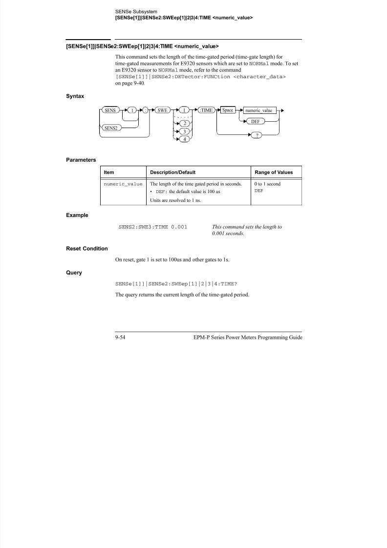
8/9/2019 E4416 Programming Guide
http://slidepdf.com/reader/full/e4416-programming-guide 394/615
SENSe Subsystem
[SENSe[1]]|SENSe2:SWEep[1]|2|3|4:TIME <numeric_value>
EPM-P Series Power Meters Programming Guide 9-55
Query Example
Error Messages
• If the command is used when a non E9320 sensor is connected, the
error -241, “Hardware missing” occurs.
• If the command is used when an E9320 sensor is connected and set to AVERage
mode rather than NORMal mode, the error -221, “Settings Conflict” occurs.
SENS2:SWE2:TIME? This command queries the length of the
time-gated period for channel B and gate 2.

8/9/2019 E4416 Programming Guide
http://slidepdf.com/reader/full/e4416-programming-guide 395/615
SENSe Subsystem
SENSe[1]]|SENSe2:TRACe Commands
9-56 EPM-P Series Power Meters Programming Guide
SENSe[1]]|SENSe2:TRACe Commands
These commands are used to set:
• The upper and lower limits for the trace display.
• The delay between the delayed trigger point and the start of the trace.
• The duration of the trace.
• The trace units.
Note These commands can only be used with E9320 sensors which are set to NORMal
mode.
The following commands are detailed in this section:
[SENSe[1]]|SENSe2:TRACe:LIMit:LOWer <numeric_value>[SENSe[1]]|SENSe2:TRACe:LIMit:UPPer <numeric_value>[SENSe[1]]|SENSe2:TRACe:OFFSet:TIME <numeric_value>[SENSe[1]]|SENSe2:TRACe:TIME <numeric_value>[SENSe[1]]|SENSe2:TRACe:UNIT <character_data>

8/9/2019 E4416 Programming Guide
http://slidepdf.com/reader/full/e4416-programming-guide 396/615
SENSe Subsystem
SENSe[1]|2:TRACe:LIMit:LOWer <numeric_value>
EPM-P Series Power Meters Programming Guide 9-57
SENSe[1]|2:TRACe:LIMit:LOWer <numeric_value>
This command sets the lower scale limit of the trace for the specified channel.
The units used are dependent on the current setting of SENS:TRAC:UNIT as shown
in the following table:
Table 0-13: Measurement Units
Note The trace lower scale limit is maintained at a lower power than the upper scale
limit which is adjusted to be slightly greater than the lower scale limit if
necessary. Refer to SENSe[1]|2:TRACe:LIMit:UPPer<numeric_value> for further information on setting the trace upper scale
limit.
Syntax
Units:
SENS:TRAC:UNIT
Units:
SENS:TRAC:LIM:LOW
dBm dBm
W W
:SENS 1
2
:TRAC Space
?
numeric_value
DEF
MIN
MAX
MIN
MAX
Space
:LOW:LIM

8/9/2019 E4416 Programming Guide
http://slidepdf.com/reader/full/e4416-programming-guide 397/615
SENSe Subsystem
SENSe[1]|2:TRACe:LIMit:LOWer <numeric_value>
9-58 EPM-P Series Power Meters Programming Guide
Parameters
Example
Reset Condition
On reset, the value is set to -50 dBm.
Query
SENSe[1]|2:TRACe:LIMit:LOWer [MIN|MAX]
The query returns the current setting of the trace lower scale limit or the value
associated with MIN or MAX. The format of the response is <NR3>.
Query Example
Item Description/Default Range of Values
numeric_value A numeric value for the trace lower scale
limit.
• DEF: the default is 20 dBm
• MIN: -150 dBm
• MAX: 230 dBm
Units used are resolved to 1 dBm
-150 to 230 dBm
DEF
MIN
MAX
SENS2:TRAC:LIM:LOW 10 This command sets the trace lower
scale limit to 10 dBm for
channel B.
SENSe:TRAC:LIM:LOW? This command queries the trace lower
scale limit of channel A.

8/9/2019 E4416 Programming Guide
http://slidepdf.com/reader/full/e4416-programming-guide 398/615
SENSe Subsystem
SENSe[1]|2:TRACe:LIMit:UPPer <numeric_value>
EPM-P Series Power Meters Programming Guide 9-59
SENSe[1]|2:TRACe:LIMit:UPPer <numeric_value>
This command sets the upper scale limit of the trace for the specified channel.
The units used are dependent on the current setting of SENS:TRAC:UNIT as shown
in the following table:
Table 0-14: Measurement Units
Note The trace lower scale limit is maintained at a lower power than the upper scale
limit which is adjusted to be slightly greater than the lower scale limit if
necessary. Refer to SENSe[1]|2:TRACe:LIMit:LOWer<numeric_value> for further information on setting the trace lower scale
limit.
Syntax
Units:
SENS:TRAC:UNIT
Units:
SENS:TRAC:LIM:UPP
dBm dBm
W W
:SENS 1
2
:TRAC Space
?
numeric_value
DEF
MIN
MAX
MIN
MAX
Space
:UPP:LIM

8/9/2019 E4416 Programming Guide
http://slidepdf.com/reader/full/e4416-programming-guide 399/615
SENSe Subsystem
SENSe[1]|2:TRACe:LIMit:UPPer <numeric_value>
9-60 EPM-P Series Power Meters Programming Guide
Parameters
Example
Reset Condition
On reset, the value is set to DEF.
Query
SENSe[1]|2:TRACe:LIMit:LOWer [MIN|MAX]
The query returns the current setting of the trace upper scale limit or the value
associated with MIN or MAX. The format of the response is <NR3>.
Query Example
Item Description/Default Range of Values
numeric_value A numeric value for the trace upper scale
limit.
• DEF: the default is 20 dBm
• MIN: -150 dBm
• MAX: 230 dBm
Units used are resolved to 1 dBm
-150 to 230 dBm
DEF
MIN
MAX
SENS:TRAC:LIM:UPP 100 This command sets the trace upper
scale limit to 100 dBm for
channel A.
SENS:TRAC:LIM:UPP? This command queries the trace upper
scale limit of channel A.

8/9/2019 E4416 Programming Guide
http://slidepdf.com/reader/full/e4416-programming-guide 400/615
SENSe Subsystem
[SENSe[1]]|SENSe2:TRACe:OFFSet:TIME <numeric_value>
EPM-P Series Power Meters Programming Guide 9-61
[SENSe[1]]|SENSe2:TRACe:OFFSet:TIME <numeric_value>
This command sets the delay between the delayed trigger point and the start of the
trace for E9320 sensors which are set to NORMal mode.To set an E9320 sensor to NORMal mode, refer to the command
[SENSe[1]]|SENSe2:DETector:FUNCtion <character_data>on page 9-40.
syntax
Parameters
Example
Reset Condition
On reset, the delay is set to 0 seconds.
Query
SENSe[1]]|SENSe2:TRACe:OFFSet:TIME?
The query returns the current delay between the delayed trigger point and the start of
the trace.
Item Description/Default Range of Values
numeric_value The length of the delay in seconds.
• DEF: the default value is 0 seconds.
Units are resolved to 1 ns.
-1 to 1 seconds
DEF
SENS:TRAC:OFFS:TIME TIME 0.05 This command sets the delay to
0.05 seconds.
SENS 1 :TIME
SENS2
: numeric_value
DEF
SpaceTRAC
?
:OFFS

8/9/2019 E4416 Programming Guide
http://slidepdf.com/reader/full/e4416-programming-guide 401/615
SENSe Subsystem
[SENSe[1]]|SENSe2:TRACe:OFFSet:TIME <numeric_value>
9-62 EPM-P Series Power Meters Programming Guide
Query Example
Error Messages
• If the command is used when a non E9320 sensor is connected, the
error -241, “Hardware missing” occurs.
• If the command is used when an E9320 sensor is connected and set to AVERage
mode rather than NORMal mode, the error -221, “Settings Conflict” occurs.
SENS:TRAC:OFFS:TIME? This command queries the current
delay between the delayed trigger point
and the start of the trace for channel A.

8/9/2019 E4416 Programming Guide
http://slidepdf.com/reader/full/e4416-programming-guide 402/615
SENSe Subsystem
[SENSe[1]]|SENSe2:TRACe:TIME <numeric_value>
EPM-P Series Power Meters Programming Guide 9-63
[SENSe[1]]|SENSe2:TRACe:TIME <numeric_value>
This command sets the duration of the trace for E9320 sensors which are set to
NORMal mode. To set the E9320 sensor to NORMal mode, refer to the commandSENSe[1]]|SENSe2:DETector:FUNCtion <character_data>on page 9-40.
Syntax
Parameters
Example
Reset Condition
On reset, the duration is set to 100 us.
Query
SENSe[1]]|SENSe2:TRACe:TIME?
The query returns the current duration of the trace.
Item Description/Default Range of Values
numeric_value The duration of the trace in seconds.
• DEF: the default value is 100 us.Units are resolved to 1 ns.
10 us to 1 second
DEF
SENS2:TRAC:TIME 0.5 This command sets the duration of the
trace to 0.5 seconds for
channel B.
SENS 1
SENS2
: numeric_value
DEF
SpaceTRAC :TIME
?

8/9/2019 E4416 Programming Guide
http://slidepdf.com/reader/full/e4416-programming-guide 403/615
SENSe Subsystem
[SENSe[1]]|SENSe2:TRACe:TIME <numeric_value>
9-64 EPM-P Series Power Meters Programming Guide
Query Example
Error Messages
• If the command is used when a non E9320 sensor is connected, the
error -241, “Hardware missing” occurs.
• If the command is used when an E9320 sensor is connected and set to AVERage
mode rather than NORMal mode, the error -221, “Settings Conflict” occurs.
SENS2:TRAC:TIME? This command queries the current
duration of the trace.

8/9/2019 E4416 Programming Guide
http://slidepdf.com/reader/full/e4416-programming-guide 404/615
SENSe Subsystem
[SENSe[1]]|SENSe2:TRACe:UNIT <character_data>
EPM-P Series Power Meters Programming Guide 9-65
[SENSe[1]]|SENSe2:TRACe:UNIT <character_data>
This command sets the units for the trace for the specified channel.
Syntax
Parameters
Example
Reset Condition
On reset the units are set to dBm.
Query[SENSe[1]]|SENSe2:TRACe:UNIT?
The query command returns the current value of character_data.
Query Example
Item Description/Default Range of Values
character_data • DBM: dBm.
• W: Watts.
DBM W
SENS2:TRAC:UNIT W This command sets the trace units for
channel B to Watts.
SENS2:TRAC:UNIT? This command queries the current trace
units for channel B.
SENS :TRAC Space character_data
?
1
2
:UNIT

8/9/2019 E4416 Programming Guide
http://slidepdf.com/reader/full/e4416-programming-guide 405/615
SENSe Subsystem
[SENSe[1]]|SENSe2:V2P ATYPe|DTYPe
9-66 EPM-P Series Power Meters Programming Guide
[SENSe[1]]|SENSe2:V2P ATYPe|DTYPe
This command is used to select the type of linearity correction that will be applied to
the channel sensors being used. For most 8480 Series power sensors, the correct (Atype or D type) linearity correction table is automatically selected. However, for the
V8486A and W8486A sensors the automatic selection must be overridden and the D
type (diode) correction selected.
Note This command is only applicable for V8486A and W8486A sensors.
Syntax
Example
Reset Condition
On reset, the linearity correction is set for A type.
Query
[SENSe[1]]|SENSe2:V2P?
The query returns the current type of linearity correction being displayed on thescreen.
Query Example
Error Messages
If no sensor is connected or the sensor is not an A type, the error -241, “Hardware
missing” occurs.
SENS2:V2P DTYP This command selects the D type
linearity correction to be applied tochannel B.
SENS:V2P? This command queries which linearity
correction type is currently being
displayed on the screen.
SENS 1
SENS2
: V2P ATYP
DTYP
Space
?

8/9/2019 E4416 Programming Guide
http://slidepdf.com/reader/full/e4416-programming-guide 406/615
10
STATus Subsystem

8/9/2019 E4416 Programming Guide
http://slidepdf.com/reader/full/e4416-programming-guide 407/615
STATus Subsystem
STATus Subsystem
10-2 EPM-P Series Power Meters Programming Guide
STATus Subsystem
The STATus command subsystem enables you to examine the status of the power
meter by monitoring the following status registers:
• Device status register.
• Operation status register.
• Questionable status register.
The contents of these and other registers in the power meter are determined by one or
more status registers.
Table 0-15 summarizes the effects of various commands and events on these status
registers:
Table 0-15: Commands and events affecting Status Registers
The contents of the status registers are examined using the following status register
set commands:
:CONDition?:ENABle <NRf>|<non-decimal numeric>[:EVENt?]
:NTRansition <NRf>|<non-decimal numeric>:PTRansition <NRf>|<non-decimal numeric>
Status Register *RST *CLS Power OnSTATus:
PRESet
SCPI Transition Filters (NTR
and PTR registers)
none none preset preset
SCPI Enable Registers none none preset preset
SCPI Event Registers none clear clear none
SCPI Error/Event Queue
enable
none none preset preset
SCPI Error/Event Queue none clear clear none
IEEE488.2 Registers
ESE SRE
none none clear none
IEEE488.2 Registers
SESR STBnone clear clear none
STAT S b

8/9/2019 E4416 Programming Guide
http://slidepdf.com/reader/full/e4416-programming-guide 408/615
STATus Subsystem
STATus Subsystem
EPM-P Series Power Meters Programming Guide 10-3
Each of these can be used to examine any of the following eleven status registers:
STATus:DEVice ( page 10-8)
STATus:OPERation ( page 10-11)
STATus:OPERation:CALibrating[:SUMMary] ( page 10-12)STATus:OPERation:LLFail[:SUMMary] ( page 10-13)
STATus:OPERation:MEASuring[:SUMMary] ( page 10-14)
STATus:OPERation:SENSe[:SUMMary] ( page 10-15)
STATus:OPERation:TRIGger[:SUMMary] ( page 10-16)
STATus:OPERation:ULFail[:SUMMary] ( page 10-17)
STATus:QUEStionable ( page 10-20)
STATus:QUEStionable:CALibration[:SUMMary] ( page 10-21)
STATus:QUEStionable:POWer[:SUMMary] ( page 10-22)
Examples:
• To use the :CONDition? command to examine the STATus:DEVice register:
STATus:DEVice:CONDition?
• To use the :NTRansition command to examine the
STATus:OPERation:SENSe[:SUMMary] register:
STATus:OPERation:SENSe[:SUMMary]:NTRansition
This chapter describes the status register set commands and the status registers whichthey are used to examine.

8/9/2019 E4416 Programming Guide
http://slidepdf.com/reader/full/e4416-programming-guide 409/615
STATus Subsystem

8/9/2019 E4416 Programming Guide
http://slidepdf.com/reader/full/e4416-programming-guide 410/615
STATus Subsystem
Status Register Set Commands
EPM-P Series Power Meters Programming Guide 10-5
:ENABle <NRf>|<non-decimal numeric>
This command sets the Enable Register of the particular SCPI Register Set you
require to control. The parameter value, when rounded to an integer and expressed in
base 2 has it’s first 15 bits written into the Enable Register of the SCPI Register Setconcerned. The last bit (bit 15) is always set to 0.
Syntax
Parameters
Query
:ENABle?
The query returns a 15 bit decimal-weighted number representing the contents of the
Enable Register of the SCPI Register Set being queried. The format of the return is
<NR1> in the range of 0 to 32767 (215-1).
Type Description Range of Values
NRf The value used to set the
Enable Register.
0 to 216-1
non-decimal numeric
:ENAB NRf
non-decimal numeric
?
space
STATus Subsystem

8/9/2019 E4416 Programming Guide
http://slidepdf.com/reader/full/e4416-programming-guide 411/615
STATus Subsystem
Status Register Set Commands
10-6 EPM-P Series Power Meters Programming Guide
:NTRansition <NRf>|<non-decimal numeric>
This command sets the Negative Transition Register of the SCPI Register Set you
require to control. The parameter value, when rounded to an integer and expressed in
base 2 has it’s first 15 bits written into the Negative Transition Register of the SCPIRegister Set concerned. The last bit (bit 15) is always set to 0.
Syntax
Parameters
Query
:NTRansition?
The query returns a 15 bit decimal-weighted number representing the contents of the
Negative Transition Register of the SCPI register set being queried. The format of the
return is <NR1> in the range of 0 to 32767 (215-1).
Type Description Range of Values
NRf The value used to set the
NTR Register.
0 to 216-1
non-decimal numeric
NRf
non-decimal numeric
?
:NTR space
STATus Subsystem

8/9/2019 E4416 Programming Guide
http://slidepdf.com/reader/full/e4416-programming-guide 412/615
y
Status Register Set Commands
EPM-P Series Power Meters Programming Guide 10-7
:PTRansition <NRf>|<non-decimal numeric>
This command is used to set the Positive Transition Register of the SCPI Register Set
you require to control. The first 15 bits of the input parameter are written into the
Positive Transition Register of the SCPI Register Set concerned. The last bit (bit 15)is always set to 0.
Syntax
Parameters
Query
:PTRansition?
The query returns a 15 bit decimal-weighted number representing the contents of the
Positive Transition Register of the SCPI register set being queried. The format of the
return is <NR1> in the range of 0 to 32767 (215-1).
Type Description Range of Values
NRf The value used to set the
PTR Register.
0 to 216-1
non-decimal numeric
NRf
non-decimal numeric
?
:PTR space
STATus Subsystem

8/9/2019 E4416 Programming Guide
http://slidepdf.com/reader/full/e4416-programming-guide 413/615
y
Device Status Register Sets
10-8 EPM-P Series Power Meters Programming Guide
Device Status Register Sets
The status registers contain information which give device status information. The
contents of the individual registers of these register sets may be accessed byappending the commands listed in “Status Register Set Commands”.
The following command descriptions detail the SCPI register you require to control
but do not detail the register set commands.
The one device status register set is:
STATus:DEVice:
The following bits in these registers are used by the power meter:
Bit
Number
Decimal
Weight Definition
0 - Not used
1 2 Channel A sensor connected
2 4 Channel B sensor connected (E4417A only)
3 8 Channel A sensor error
4 16 Channel B sensor error (E4417A only)
5 32 Channel A sensor Front/Rear
6 64 Channel B sensor Front/Rear (E4417A only)
7-15 - Not used
14 16384 Front Panel key press
15 - Bit 15 always 0
STATus Subsystem

8/9/2019 E4416 Programming Guide
http://slidepdf.com/reader/full/e4416-programming-guide 414/615
Device Status Register Sets
EPM-P Series Power Meters Programming Guide 10-9
The Channel A and B sensor connected bits (bits 1 and 2), when queried with the
STATus:DEVice:CONDition? query are set to:
• 1, when a power sensor is connected.
• 0, when no power sensor is connected.
The Channel A and B sensor connected bits (bits 1 and 2), when queried with the
STATus:DEVice:EVENt? query indicate whether a power sensor has been
connected or disconnected depending on the state of the corresponding bits of
STATus:DEVice:NTRansition and STATus:DEVice:PTRansition. If
the corresponding bit in:
• STATus:DEVice:NTRansition is 1, then STATus:DEVice:EVENt? is set when a power sensor is disconnected.
Note, querying STATus:DEVice:EVENt? clears theSTATus:DEVice:EVENt?register.
• STATus:DEVice:PTRansition is 1, then STATus:DEVice:EVENt? is set when a power sensor is connected.
Note, querying STATus:DEVice:EVENt? clears the
STATus:DEVice:EVENt?register.
The Channel A and B sensor error bits (3 and 4) are set to:
• 1, if the Agilent E-Series or N8480 Series power sensor EEPROM has failed
or if there are power sensors connected to both the rear and front panelconnectors.
• 0, for every other condition.
The Channel A and B sensor Front/Rear bits (bits 5 and 6) are set to:
• 1, if the power sensor is connected to the rear panel.
• 0, if the power sensor is connected to the front panel.
The Front Panel key press bit (bit 14), when queried with the
STATus:DEVice:EVENt? query indicates whether any front panel keys have been pressed since power up or since you last queried the device status register. This
bit ignores the:NTRansition, and :PTRansition registers and
a:CONDition? query always returns a 0.
STATus Subsystem
O ti R i t S t
8/9/2019 E4416 Programming Guide
http://slidepdf.com/reader/full/e4416-programming-guide 415/615
Operation Register Sets
10-10 EPM-P Series Power Meters Programming Guide
Operation Register Sets
The following registers contain information which is part of the power meter’s
normal operation. The contents of the individual registers of these register sets may be accessed by appending the commands listed in “Status Register Set Commands”.
The following command descriptions detail the SCPI register you require to control
but do not detail the Register Set commands.
The seven Operation Register Sets are:
STATUS:OPERationSTATus:OPERation:CALibrating[:SUMMary]STATus:OPERation:LLFail[:SUMMary]
STATus:OPERation:MEASuring[:SUMMary]STATus:OPERation:SENSe[:SUMMary]STATus:OPERation:TRIGger[:SUMMary]STATus:OPERation:ULFail[:SUMMary]
Further information on these register sets is provided on the following pages.
STATus Subsystem
STATus:OPERation

8/9/2019 E4416 Programming Guide
http://slidepdf.com/reader/full/e4416-programming-guide 416/615
STATus:OPERation
EPM-P Series Power Meters Programming Guide 10-11
STATus:OPERation
The operation status register set contains conditions which are a part of the operation
of the power meter as a whole.
The following bits in these registers are used by the power meter:
Syntax
Bit
Number
Decimal
Weight Definition
0 1 CALibrating Summary
1 - 3 - Not used
4 16 MEASuring Summary
5 32 Waiting for TRIGger Summary
6 - 9 - Not used
10 1024 SENSe Summary
11 2048 Lower Limit Fail Summary
12 4096 Upper Limit Fail Summary
13 to 15 - Not used (bit 15 always 0)
STAT :OPER
STATus Subsystem
STATus:OPERation:CALibrating[:SUMMary]

8/9/2019 E4416 Programming Guide
http://slidepdf.com/reader/full/e4416-programming-guide 417/615
STATus:OPERation:CALibrating[:SUMMary]
10-12 EPM-P Series Power Meters Programming Guide
STATus:OPERation:CALibrating[:SUMMary]
The operation status calibrating summary register set contains information on the
calibrating status of the power meter.
The following bits in these registers are used by the power meter:
These bits are set at the beginning of zeroing (CALibration:ZERO:AUTO ONCE)
and at the beginning of calibration (CALibration:AUTO ONCE). Also for the
compound command/query CALibration[:ALL]?, this bit is set at the beginning
of the calibration sequence.
These bits are cleared at the end of zeroing or calibration.
Syntax
Bit
Number
Decimal
Weight Definition
0 - Not used
1 2 Channel A CALibrating Status
2 4 Channel B CALibrating Status (E4417A only)
3-15 - Not used
STAT :OPER :CAL :SUMM
STATus Subsystem
STATus:OPERation:LLFail[:SUMMary]

8/9/2019 E4416 Programming Guide
http://slidepdf.com/reader/full/e4416-programming-guide 418/615
STATus:OPERation:LLFail[:SUMMary]
EPM-P Series Power Meters Programming Guide 10-13
STATus:OPERation:LLFail[:SUMMary]
The operation status lower limit fail summary register set contains information on the
lower limit fail status of the power meter.
The following bits in these registers are used by the power meter:
The appropriate bits are set if a channel lower limit test fails or a window lower limit
test fails.
These bits are cleared if a measurement is made and the test is enabled and passes.
Syntax
Bit
Number
Decimal
Weight Definition
0 - Not used
1 2 Channel A LLFail Status
2 4 Channel B LLFail Status (E4417A only)
3 8 Upper window LLFail Status
4 16 Lower widow LLFail Status
5 32 Upper window lower measurement LLFail Status
6 64 Lower window lower measurement LLFail Status
7-15 - Not used
STAT :OPER :LLF :SUMM
STATus Subsystem
STATus:OPERation:MEASuring[:SUMMary]

8/9/2019 E4416 Programming Guide
http://slidepdf.com/reader/full/e4416-programming-guide 419/615
g[ y]
10-14 EPM-P Series Power Meters Programming Guide
STATus:OPERation:MEASuring[:SUMMary]
The operation status measuring summary register set contains information on the
measuring status of the power meter.
The following bits in these registers are used by the power meter:
These bits are set when the power meter is taking a measurement.
These bits are cleared when the measurement is finished.
Syntax
Note The operation status measuring summary is available only in average mode.
Refer to the Agilent N1911A/1912A P-Series Power Meters Programming
Guide, Page 791/793, example 2, on measurement polling when using a
VEE Programme.
Bit
Number
Decimal
Weight Definition
0 - Not used
1 2 Channel A MEASuring Status
2 4 Channel B MEASuring Status (E4417A only)
3-15 - Not used
STAT :OPER :MEAS :SUMM
STATus Subsystem
STATus:OPERation:SENSe[:SUMMary]

8/9/2019 E4416 Programming Guide
http://slidepdf.com/reader/full/e4416-programming-guide 420/615
EPM-P Series Power Meters Programming Guide 10-15
STATus:OPERation:SENSe[:SUMMary]
The operation status sense summary register set contains information on the status of
the power sensors.
The following bits in these registers are used by the power meter:
These bits are set when the power meter is reading data from the Agilent E-Series or
N8480 Series power sensor EEPROM.
These bits are cleared when the power meter is not reading data from the
Agilent E-Series or N8480 Series power sensor EEPROM.
Syntax
Bit
Number
Decimal
Weight Definition
0 - Not used
1 2 Channel A SENSe Status
2 4 Channel B SENSe Status (E4417A only)
3-15 - Not used
STAT :OPER :SENS :SUMM
STATus Subsystem
STATus:OPERation:TRIGger[:SUMMary]

8/9/2019 E4416 Programming Guide
http://slidepdf.com/reader/full/e4416-programming-guide 421/615
10-16 EPM-P Series Power Meters Programming Guide
STATus:OPERation:TRIGger[:SUMMary]
The operation status trigger summary register set contains information on the trigger
status of the power meter.
The following bits in these registers are used by the power meter:
Syntax
Bit
Number
Decimal
Weight Definition
0 - Not used
1 2 Channel A TRIGger Status
2 4 Channel B TRIGger Status (E4417A only)
3-15 - Not used
STAT :OPER :TRIG :SUMM

8/9/2019 E4416 Programming Guide
http://slidepdf.com/reader/full/e4416-programming-guide 422/615
STATus Subsystem
STATus:PRESet

8/9/2019 E4416 Programming Guide
http://slidepdf.com/reader/full/e4416-programming-guide 423/615
10-18 EPM-P Series Power Meters Programming Guide
STATus:PRESet
PRESet sets a number of the status registers to their preset values as shown below -
all other registers are unaffected. Bit 15 is always 0.
Syntax
Register Filter/Enable PRESet Value
OPERational ENABle all zeros
PTR all ones
NTR all zeros
QUEStionable ENABle all zeros
PTR all ones
NTR all zeros
All Others ENABle all ones
PTR all ones
NTR all zeros
STAT :PRES
STATus Subsystem
Questionable Register Sets

8/9/2019 E4416 Programming Guide
http://slidepdf.com/reader/full/e4416-programming-guide 424/615
EPM-P Series Power Meters Programming Guide 10-19
Questionable Register Sets
The questionable register sets contain information which gives an indication of the
quality of the data produced by the power meter. The contents of the individual
registers in these register sets may be accessed by appending the commands listed in
“Status Register Set Commands”.
The following command descriptions detail the SCPI register you require to control
but do not detail the register set commands.
The three questionable register sets are:
STATus:QUEStionableSTATus:QUEStionable:CALibration[:SUMMary]
STATus:QUEStionable:POWer[:SUMMary]
STATus Subsystem
STATus:QUEStionable

8/9/2019 E4416 Programming Guide
http://slidepdf.com/reader/full/e4416-programming-guide 425/615
10-20 EPM-P Series Power Meters Programming Guide
STATus:QUEStionable
The questionable register set contains bits which give an indication of the quality of
various aspects of signals processed by the power meter as a whole.
The following bits in these registers are used by the power meter:
Bit 3 is set by the logical OR outputs of the
STATus:QUEStionable:POWer:SUMMary register set.
Bit 8 is set by the logical OR outputs of the
STATus:QUEStionable:CALibration:SUMMary register set.
Bit 9 is set if power-on self-test fails, and cleared if it passes.
Syntax
Bit
Number
Decimal
Weight Definition
0 to 2 - Not used
3 8 POWer Summary
4 to 7 - Not used
8 256 CALibration Summary
9 512 Power On Self Test
10 to 15 - Not Used (bit 15 always 0)
STAT :QUES
STATus Subsystem
STATus:QUEStionable:CALibration[:SUMMary]

8/9/2019 E4416 Programming Guide
http://slidepdf.com/reader/full/e4416-programming-guide 426/615
EPM-P Series Power Meters Programming Guide 10-21
STATus:QUEStionable:CALibration[:SUMMary]
The questionable calibration summary register set contains bits which give an
indication of the quality of the data produced by the power meter due to its calibration
status.
The following bits in these registers are used by the power meter:
These bits are set by the following:
• Error -231, “Data questionable; CH<A|B>:ZERO ERROR”
• Error -231, “Data questionable; CAL ERROR”
• Error -231, “Data questionable; CAL ERROR ChA”
• Error -231, “Data questionable; CAL ERROR ChB”
These bits are cleared when any of the three commands listed above succeed and no
errors are placed on the error queue.
Syntax
Bit
Number
Decimal
Weight Definition
0 - Not used
1 2 Summary of Channel A CALibration
2 4 Summary of Channel B CALibration (E4417A only)
3-15 - Not used
STAT :QUES :CAL :SUMM
STATus Subsystem
STATus:QUEStionable:POWer[:SUMMary]

8/9/2019 E4416 Programming Guide
http://slidepdf.com/reader/full/e4416-programming-guide 427/615
10-22 EPM-P Series Power Meters Programming Guide
STATus:QUEStionable:POWer[:SUMMary]
The questionable power summary register set contain bits which give an indication of
the quality of the power data being acquired by the power meter.
The following bits in these registers shall be used by the power meter:
Bit 1 is set when any of the following errors occur:
• Error -231, “Data questionable;Input Overload” (E4417A only)
• Error -231, “Data questionable;Input Overload ChA” (E4417A only)
Bit 2 is set when the following error occurs:
• Error -231, “Data questionable;Input Overload ChB” (E4417A only)
Bits 3 is set when the following error occurs:
• Error -230, “Data corrupt or stale”
• Error -231, “Data questionable;Upper window log error”
Bit 4 is set when the following error occurs:
• Error -230, “Data corrupt or stale”
• Error -231, “Data questionable;Lower window log error”
Bit
Number
Decimal
Weight Definition
0 - Not used
1 2 Channel A Power
2 4 Channel B Power (E4417A only)
3 8 Upper Window Power
4 16 Lower Window Power
5 32 Channel A Please Zero
6 64 Channel B Please Zero (E4417A only)
7 128 Upper Window Lower Measurement Power
8 256 Lower Window Lower Measurement Power
STATus Subsystem
STATus:QUEStionable:POWer[:SUMMary]

8/9/2019 E4416 Programming Guide
http://slidepdf.com/reader/full/e4416-programming-guide 428/615
EPM-P Series Power Meters Programming Guide 10-23
Bit 5 is set when the following condition occurs:
• Channel A requires zeroing
Bis 6 is set when the following condition occurs (E4417A only):
• Channel B requires zeroing
These bits are cleared when no errors or events are detected by the power meter
during a measurement covering the causes given for it to set.
Syntax
STAT :QUES :POW :SUMM
STATus Subsystem
STATus:QUEStionable:POWer[:SUMMary]

8/9/2019 E4416 Programming Guide
http://slidepdf.com/reader/full/e4416-programming-guide 429/615
10-24 EPM-P Series Power Meters Programming Guide
THIS PAGE HAS BEEN INTENTIONALLY LEFT BLANK.
0 1 2 3 4 5 6 7
Logical OR
t a t u s B y t e
a l P o l l , * S R E
b i t 6 R Q S )
0 1 2 3 4 5 6 7 8 9 1 0 1 1 1 2 1 3 1 4 1 5
Logical OR
D e v i c e S t a t u s
S T A T : D E V
c t e d
c t e d
r r o r
r r o r
e a r
e a r
re s s 0
y

8/9/2019 E4416 Programming Guide
http://slidepdf.com/reader/full/e4416-programming-guide 430/615
EPM-P Series Power Meters Programming Guide
0 1 2 3 4 5 6 7
O u t p u t Q
u e u e
D a t a A v a
i l a b l e
E r r o r /
E v e n t
Q u e u e
S t
S e r i ( b
S T A T : Q U E S
S e n s o r A C o n n e c
S e n s o r B C o n n e c
S e n s o r A E r
S e n s o r B E r
S e n s o r A F r o n t / R e
S e n s o r B F r o n t / R e
K e y P r
0 1 2 3 4 5 6 7 8 9 1 0 1 1 1 2 1 3 1 4 1 5
Logical OR
Q u e s t i o n a b l e P O W e r S u m m a r y
S T A T : Q U E S : P O W : S U M M
C h a n n e l A P O W e r
C h a n n e l B P O W e r
U p p e r W i n d o w , U p p e r M e a s u r e m e n t P O W e r
L o w
e r W i n d o w , U p p e r M e a s u r e m e n t P O W e r
C h a n n e l A P l e a s e Z e r o
C h a n n e l B P l e a s e Z e r o
U p p e r W i n d o w , L o w e r M e a s u r e m e n t P O W e r
L o w
e r W i n d o w , L o w e r M e a s u r e m e n t P O W e r
0 1 2 3 4 5 6 7 8 9 1 0 1 1 1 2 1 3 1 4 1 5
Logical OR
Q u e s t i o n a b l e C A L i b r a t i o n S u m m a r y
S T A T : Q U E S : C A L : S U M M
C h a n n e l A C A L i b r a t i o n
C h a n n e l B C A L i b r a t i o n
0 1 2 3 4 5 6 7 8 9 1 0 1 1 1 2 1 3 1 4 1 5
Logical OR
Q u e s t i o n a b l e S t a t u s
P O S T F a i l u r e 0
0 1 2 3 4 5 6 7 8 9 1 0 1 1 1 2 1 3 1 4 1 5
Logical OR
C h a n n e l A C A L i b r a t i o n
C h a n n e l B C A L i b r a t i o n
O
p e r a t i o n C A L i b r a t i n g S u m m a r y
S T A T : O P E R : C A L : S U M M
0 1 2 3 4 5 6 7
Logical OR
S t a n d a r d E v e n t
* E S E , * E S R ?
O p e r a t i o n C o m p l e
t e
R e q u e s t C o n t r o l ( n o t u s e d )
Q u e r y E r r o r
D e v i c e D e p e n d e n t E r r o r
E x e c u t i o n E r r o r
C o m m a n d E r r o r
U s e r R e q u e
s t
P o w e r O
n
0 1 2 3 4 5 6 7 8 9 1 0 1 1 1 2 1 3 1 4 1 5
Logical OR
O p e r a t i o n M E A S u r i n g S u m m
a r y
S T A T : O P E R : M E A S : S U M M
C h a n n e l A M E A S u r i n g
C h a n n e l B M E A S u r i n g
0 1 2 3 4 5 6 7 8 9 1 0 1 1 1 2 1 3 1 4 1 5
Logical OR
O p e r a t i o n T R I G g e r i n g S u m m a r y
S T A T : O P E R : T R I G : S U M M
C h a n n e l A W a i t i n g f o r T R I G g e r
C h a n n e l B W a i t i n g f o r T R I G g e r
0 1 2 3 4 5 6 7 8 9 1 0 1 1 1 2 1 3 1 4 1 5
Logical OR
O p e r a t i o n S E N S e S u m m a r y
S T A T : O P E R : S E N S : S U M M
C h a n n e l A S e n s o r R e a d i n g f r o m E E P R O M
C h a n n e l B S e n s o r R e a d i n g f r o m E E P R O M
0 1 2 3 4 5 6 7 8 9 1 0 1 1 1 2 1 3 1 4 1 5
Logical OR
L o w e r L i m i t F a i l S u m m a r y
S T A T : O P E R : L L F : S U M M
U p p e r W i n d o w , U p p e r M e a s u r e
m e n t L L F
L o w e r W i n d o w , U p p e r M e a s u r e
m e n t L L F
U p p e r W i n d o w , L o w e r M e a s u r e
m e n t L L F
L o w e r W i n d o w , L o w e r M e a s u r e
m e n t L L F
0 1 2 3 4 5 6 7 8 9 1 0 1 1 1 2 1 3 1 4 1 5
Logical OR
U p p e r L i m i t F a i l S u m m a r y
S T A T : O P E R : U L F : S U M M
U p p e r W i n d o w , U p p e r M e a s u r e m e n t U L F
L o w e r W i n d o w , U p p e r M e a s u r e m e n t U L F
U p p e r W i n d o w , L o w e r M e a s u r e m e n t U L F
L o w e r W i n d o w , L o w e r M e a s u r e m e n t U L F
0 1 2 3 4 5 6 7 8 9 1 0 1 1 1 2 1 3 1 4 1 5
Logical OR
O p e r a t i o n S t a t u s
S T A T : O P E R
0

8/9/2019 E4416 Programming Guide
http://slidepdf.com/reader/full/e4416-programming-guide 431/615
10-26 EPM-P Series Po
THIS PAGE HAS BEEN INTENTIONALLY LEFT BLANK.

8/9/2019 E4416 Programming Guide
http://slidepdf.com/reader/full/e4416-programming-guide 432/615
11
SYSTem Subsystem
SYSTem Subsystem
SYSTem Subsystem

8/9/2019 E4416 Programming Guide
http://slidepdf.com/reader/full/e4416-programming-guide 433/615
11-2 Agilent E4416A/E4417A Programming Guide
SYSTem Subsystem
The SYStem command subsystem is used to:
• Return error numbers and messages from the power meter.• Preset the power meter.
• Select the remote interface type (GPIB, RS232 orRS422).
• Set the GPIB address.
• Set the command language.
• Query the SCPI version.
At a lower level:
• SYSTem:COMMunicate:SERial:CONTrol sets the DTR and RTSsignal lines.
• SYSTem:COMMunicate:SERial:CONTrol[:RECeive] and
TRANsmit sets baud rate, parity, word length and other serial interface
controls.
Keyword Parameter Form Notes Page
SYSTem :COMMunicate
:GPIB
[:SELF]:ADDRess <numeric_value> page 11-4
:SERial:CONTrol
:DTR <boolean> page 11-7
:RTS <boolean> page 11-8
[:RECeive]:BAUD <numeric_value> page 11-9
:BITs <numeric_value> page 11-11
:PACE XON|NONE page 11-13
:PARity
[:TYPE] EVEN|ODD|ZERO|ONE|NONE page 11-14:SBITs <numeric_value> page 11-16
:TRANsmit:AUTO? [query only] page 11-17
:BAUD <numeric_value> page 11-18
:BITs <numeric_value> page 11-20
:ECHO <boolean> page 11-21
:PACE XON|NONE page 11-22
:PARity[:TYPE] EVEN|ODD|ZERO|ONE|NONE page 11-23
:SBITs <numeric_value> page 11-25
:HELP:HEADers? [query only] page 11-26
SYSTem Subsystem
SYSTem Subsystem

8/9/2019 E4416 Programming Guide
http://slidepdf.com/reader/full/e4416-programming-guide 434/615
Agilent E4416A/E4417A Programming Guide 11-3
:LoCAL page 11-27
:PRESet character_data [event; no
query]
page 11-28
:REMote page 11-58:RINTerface GPIB|RS232|RS422 page 11-59
:RWLock page 11-60
:VERSion? [query only] page 11-61
Keyword Parameter Form Notes Page
SYSTem Subsystem
SYSTem:COMMunicate:GPIB[:SELF]:ADDRess <numeric_value>

8/9/2019 E4416 Programming Guide
http://slidepdf.com/reader/full/e4416-programming-guide 435/615
11-4 Agilent E4416A/E4417A Programming Guide
SYSTem:COMMunicate:GPIB[:SELF]:ADDRess <numeric_value>
This command sets the GPIB address of the power meter.
Syntax
Parameters
Example
Query
SYSTem:COMMunicate:GPIB[:SELF]:ADDRess? MIN|MAX
The query returns the current setting of the GPIB address or the values associated
with MIN and MAX.
Item Description/Default Range of Values
numeric_value A numeric value for the address.
• DEF: the default value is 13.
• MIN: 0.
• MAX: 30.
0 to 30
DEF
MIN
MAX
SYST:COMM:GPIB:ADDR 13 This command sets the GPIB address to
13.
SYST :COMM :GPIB :SELF :ADDR Space
?
numeric_value
DEF
MIN
MAX
MIN
MAX
Space
SYSTem Subsystem
SYSTem:COMMunicate:GPIB[:SELF]:ADDRess <numeric_value>

8/9/2019 E4416 Programming Guide
http://slidepdf.com/reader/full/e4416-programming-guide 436/615
Agilent E4416A/E4417A Programming Guide 11-5
Query Example
SYST:COMM:GPIB:ADDR? This command queries the setting of the
GPIB address.
SYSTem Subsystem
SYStem:COMMunicate:Serial Commands

8/9/2019 E4416 Programming Guide
http://slidepdf.com/reader/full/e4416-programming-guide 437/615
11-6 Agilent E4416A/E4417A Programming Guide
SYStem:COMMunicate:Serial Commands
These commands control the settings for the RS232/RS422 serial interface. The
commands allow you to:
• Set the function of the DTR and RTS signal lines.
• Set the transmit/receive baud rate.
• Set the transmit/receive word length.
• Set the transmit/receive parity type.
• Set the transmit/receive stop bits.
• Enable /disable XON/XOFF software handshaking.
The following commands are detailed in this section:
SYSTem:COMMunicate:SERial:CONTrol:DTRSYSTem:COMMunicate:SERial:CONTrol:RTSSYSTem:COMMunicate:SERial:[:RECeive]:BAUDSYSTem:COMMunicate:SERial:[:RECeive]:BITsSYSTem:COMMunicate:SERial:[:RECeive]:PACESYSTem:COMMunicate:SERial:[:RECeive]:PARity:[TYPE]SYSTem:COMMunicate:SERial:[:RECeive]:SBITsSYSTem:COMMunicate:SERial:TRANsmit:AUTO?SYSTem:COMMunicate:SERial:TRANsmit:BAUD
SYSTem:COMMunicate:SERial:TRANsmit:BITsSYSTem:COMMunicate:SERial:TRANsmit:ECHOSYSTem:COMMunicate:SERial:TRANsmit:PARity:[TYPE]SYSTem:COMMunicate:SERial:TRANsmit:SBITs
SYSTem Subsystem
SYSTem:COMMunicate:SERial:CONTrol:DTR <boolean>

8/9/2019 E4416 Programming Guide
http://slidepdf.com/reader/full/e4416-programming-guide 438/615
Agilent E4416A/E4417A Programming Guide 11-7
SYSTem:COMMunicate:SERial:CONTrol:DTR <boolean>
This command sets the serial interface (RS232) DTR signal line either high always
(ON) or low always (OFF). In addition, the DTR signal line can be tied to the
condition of the interface receiver buffer (IBFull) resulting in the line going highwhen the receiver is ready to accept data and low when the receiver buffer is full (not
ready for data). Also, with DTR in IBFull mode, the transmitter will be inhibited
when DSR is low.
Syntax
Example
Reset Condition
On reset, the DTR signal line setting is unaffected.
Query
SYSTem:COMMunicate:SERial:CONTrol:DTR?
The query returns the current DTR signal line setting, ON, OFF or IBFull.
Query Example
Error messages
If the RS422 interface is selected, then the error message -221 “Settings conflict” will
occur.
SYST:COMM:SER:CONT:DTR ON This command sets the DTR signal line
high (always).
SYST:COMM:SER:CONT:DTR? This command queries the setting of the
DTR signal line.
SYST :COMM :SER :DTR :CONT Space
?
ON
OFF
IBFull
SYSTem Subsystem
SYSTem:COMMunicate:SERial:CONTrol:RTS <boolean>

8/9/2019 E4416 Programming Guide
http://slidepdf.com/reader/full/e4416-programming-guide 439/615
11-8 Agilent E4416A/E4417A Programming Guide
SYSTem:COMMunicate:SERial:CONTrol:RTS <boolean>
This command is used to set the serial interface (RS232 or RS422) RTS signal line
either high always (ON) or low always (OFF). In addition, the RTS signal line can be
tied to the condition of the interface receiver buffer (IBFull) resulting in the linegoing high when the receiver is ready to accept data and low when the receiver buffer
is full (not ready for data). Also, with RTS in IBFull mode, the transmitter will be
inhibited when CTS is low.
Syntax
Example
Reset Condition
On reset, the condition of the RTS signal line is unaffected.
Query
SYSTem:COMMunicate:SERial:CONTrol:RTS?
The query returns the current RTS signal line setting, ON, OFF or IBFull.
Query Example
SYST:COMM:SER:CONT:RTS ON This command sets the RTS signal line
high (always).
SYST:COMM:SER:CONT:RTS? This command queries the setting of the
RTS signal line.
SYST :COMM :SER :RTS:CONT Space
?
ON
OFF
IBFull
SYSTem Subsystem
SYSTem:COMMunicate:SERial[:RECeive]:BAUD <numeric_value>

8/9/2019 E4416 Programming Guide
http://slidepdf.com/reader/full/e4416-programming-guide 440/615
Agilent E4416A/E4417A Programming Guide 11-9
SYSTem:COMMunicate:SERial[:RECeive]:BAUD <numeric_value>
This command sets the baud rate for both the receiver and the transmitter. The baud
rate for the receiver and transmitter are tied together and can either be set by this
command or the equivalent transmitter command :TRANsmit:BAUD.
Syntax
Parameters
Example
Reset Condition
On reset, the baud rate is unaffected.
Item Description/Default Range of Values
numeric_value A numeric value for the baud rate.
• DEF: the default value is 9600.• MIN: 50.
• MAX: 115200.
50, 75, 110, 150, 300,
1200, 1800, 2000,
2400, 3600, 4800,
7200, 9600, 19200,
38400, 57600, 115200
DEF
MIN
MAX
SYST:COMM:SER:REC:BAUD 38400 This command sets the receiver and
transmitter baud rate to 38400.
SYST :COMM :SER :REC :BAUD Space
?
numeric_value
DEF
MIN
MAX
MIN
MAX
Space
SYSTem Subsystem
SYSTem:COMMunicate:SERial[:RECeive]:BAUD <numeric_value>
Q

8/9/2019 E4416 Programming Guide
http://slidepdf.com/reader/full/e4416-programming-guide 441/615
11-10 Agilent E4416A/E4417A Programming Guide
Query
SYSTem:COMMunicate:SERial[:RECeive]:BAUD? MIN|MAX
The query returns the current setting of the receive/transmit baud rate or the values
associated with MIN and MAX.
Query Example
Error Messages
If the baud rate is not in the range of values shown in the parameter table, the error
message -224, “Illegal parameter value” occurs.
SYST:COMM:SER:REC:BAUD? This command queries the setting of the
receive/transmit baud rate.
SYSTem Subsystem
SYSTem:COMMunicate:SERial[:RECeive]:BITs <numeric_value>

8/9/2019 E4416 Programming Guide
http://slidepdf.com/reader/full/e4416-programming-guide 442/615
Agilent E4416A/E4417A Programming Guide 11-11
SYSTem:COMMunicate:SERial[:RECeive]:BITs <numeric_value>
This command sets the word length for both the receiver and the transmitter. The
word length for the receiver and transmitter are tied together and can either be set by
this command or the equivalent transmitter command :TRANsmit:BITs.
Syntax
Parameters
Example
Reset Condition
On reset, the word length is unaffected.
Query
SYSTem:COMMunicate:SERial[:RECeive]:BITs?
The query returns the current setting of the receive/transmit word length.
Query Example
Item Description/Default Range of Values
numeric_value A numeric value for the word length 7 or 8
SYST:COMM:SER:REC:BITs 8 This command sets the receiver andtransmitter word length to 8.
SYST:COMM:SER:REC:BITs? This command queries the setting of the
receive/transmit word length.
SYST :COMM :SER :REC :BIT Space numeric_value
?
SYSTem Subsystem
SYSTem:COMMunicate:SERial[:RECeive]:BITs <numeric_value>
Error Messages

8/9/2019 E4416 Programming Guide
http://slidepdf.com/reader/full/e4416-programming-guide 443/615
11-12 Agilent E4416A/E4417A Programming Guide
Error Messages
If the word length is not in the range of values shown in the parameter table, then the
error message -224, “Illegal parameter value” will occur.
SYSTem Subsystem
SYSTem:COMMunicate:SERial[:RECeive]:PACE XON|NONE

8/9/2019 E4416 Programming Guide
http://slidepdf.com/reader/full/e4416-programming-guide 444/615
Agilent E4416A/E4417A Programming Guide 11-13
SYSTem:COMMunicate:SERial[:RECeive]:PACE XON|NONE
This command enables (XON) and disables (NONE) an Xon/Xoff software handshake
for the receiver. When enabled, an Xon control character is transmitted when the
receiver is ready to accept data and an Xoff control character is transmitted when thereceiver is unable to receive further data (not ready for data).
Syntax
Example
Reset Condition
On reset, pacing is unaffected.
Query
SYSTem:COMMunicate:SERial[:RECeive]:PACE?
The query returns XON if the handshake is enabled and NONE if the handshake is
disabled.
Query Example
SYST:COMM:SER:REC:PACE XON This command enables the receiver
Xon/Xoff software handshake.
SYST:COMM:SER:REC:PACE? This command queries whether the
receiver Xon/Xoff software handshake
is enabled ( XON ) or disabled ( NONE ).
SYST :COMM :SER :PACE:REC Space
?
XON
NONE
SYSTem Subsystem
SYSTem:COMMunicate:SERial[:RECeive]:PARity[:TYPE] EVEN|ODD|ZE-
RO|ONE|NONE

8/9/2019 E4416 Programming Guide
http://slidepdf.com/reader/full/e4416-programming-guide 445/615
11-14 Agilent E4416A/E4417A Programming Guide
SYSTem:COMMunicate:SERial[:RECeive]:PARity[:TYPE] EVEN|ODD|ZERO|ONE|NONE
This command decides what type of parity checking (if any) will take place on
received data and also decides what parity (if any) will be included with transmitted
data. The following choices are available and can be set using either this command orthe equivalent TRANsmit:PARity[:TYPE] command.
Parity Type Description
EVEN The receiver expects a parity bit. All data received is
checked for even parity. An error is generated if this test
fails. Transmitted data includes a parity bit set for even
parity indication.
ODD The receiver expects a parity bit. All data received is
checked for odd parity. An error is generated if this test
fails. Transmitted data includes a parity bit set for odd
parity indication.
ZERO The receiver expects a parity bit. All data received has the
parity checked and if it is not a logic low an error will be
generated. Transmitted data includes a parity bit that is
always set low (stick 0 parity).
ONE The receiver expects a parity bit. All data received has the
parity checked and if it is not a logic high an error will be
generated. Transmitted data includes a parity bit that is
always set high (stick 1 parity).
NONE The receiver is not expecting a parity bit included in
received data and does not perform a parity check. The
transmitter does not include a parity bit in the transmitted
data.
SYSTem Subsystem
SYSTem:COMMunicate:SERial[:RECeive]:PARity[:TYPE] EVEN|ODD|ZERO|ONE|NONE
Syntax

8/9/2019 E4416 Programming Guide
http://slidepdf.com/reader/full/e4416-programming-guide 446/615
Agilent E4416A/E4417A Programming Guide 11-15
y
Example
Reset Condition
On reset, the parity setting is unaffected.
Query
SYSTem:COMMunicate:SERial[:RECeive]:PARity[:TYPE]?
The query returns the current setting of the receive/transmit parity type (EVEN, ODD,
ZERO, ONE or NONE).
Query Example
SYST:COMM:SER:REC:PAR ODD This command sets the transmitter to
include an odd parity bit in the
transmitted data and the receiver to
check for odd parity in the received
data.
SYST:COMM:SER:REC:PAR? This command queries what type of
parity has been set on the
received/transmitted data.
SYST :COMM :SER :PAR Space
?
EVEN
ODD
ZERO
:TYPE:REC
ONE
NONE
SYSTem Subsystem
SYSTem:COMMunicate:SERial[:RECeive]:SBITs <numeric_value>
SYST COMM i t SERi l[ REC i ] SBIT < i l >

8/9/2019 E4416 Programming Guide
http://slidepdf.com/reader/full/e4416-programming-guide 447/615
11-16 Agilent E4416A/E4417A Programming Guide
SYSTem:COMMunicate:SERial[:RECeive]:SBITs <numeric_value>
This command sets the number of stop bits expected by the receiver on received data
and the number of stop bits included by the transmitter in transmitted data.
Syntax
Parameters
Example
Reset Condition
On reset, the number of stop bits is unaffected.
Query
SYSTem:COMMunicate:SERial[:RECeive]:SBITs?
The query returns the current setting of the receive/transmit stop bits.
Query Example
Item Description/Default Range of Values
numeric_value A numeric value for the number of stop bits. 1 or 2
SYST:COMM:SER:REC:SBIT 2 This command sets the number of stop
bits for the receiver and transmitter to
2.
SYST:COMM:SER:REC:SBIT? This command queries the setting of the
receive/transmit stop bits.
SYST :COMM :SER :REC :SBIT Space numeric_value
?
SYSTem Subsystem
SYSTem:COMMunicate:SERial:TRANsmit:AUTO?
SYSTem:COMMunicate:SERial:TRANsmit:AUTO?

8/9/2019 E4416 Programming Guide
http://slidepdf.com/reader/full/e4416-programming-guide 448/615
Agilent E4416A/E4417A Programming Guide 11-17
SYSTem:COMMunicate:SERial:TRANsmit:AUTO?
This query always returns a 1 confirming that the transmitter parameter settings for
baud rate, word length, stop bits and parity are coupled to the receiver values.
Syntax
Example
SYST:COMM:SER:TRAN:AUTO? This command always returns a 1 to show that the transmitter and receiver
settings for baud rate, word length, stop
bits and parity are the same.
SYST :COMM :SER :TRAN :AUTO ?
SYSTem Subsystem
SYSTem:COMMunicate:SERial:TRANsmit:BAUD <numeric_value>
SYSTem:COMMunicate:SERial:TRANsmit:BAUD <numeric value>

8/9/2019 E4416 Programming Guide
http://slidepdf.com/reader/full/e4416-programming-guide 449/615
11-18 Agilent E4416A/E4417A Programming Guide
SYSTem:COMMunicate:SERial:TRANsmit:BAUD <numeric_value>
This command sets the baud rate for both the transmitter and the receiver. The baud
rate for the transmitter and receiver are tied together and can either be set by this
command or the equivalent receiver command [RECeive]:BAUD.
Syntax
Parameters
Example
Reset Condition
On reset, the baud rate is unaffected.
Item Description/Default Range of Values
numeric_value A numeric value for the baud rate.
• DEF: the default value is 9600.
• MIN: 50.
• MAX: 115200.
50, 75, 110, 150, 300,
1200, 1800, 2000,
2400, 3600, 4800,
7200, 9600, 19200,
38400, 57600, 115200
DEF
MIN
MAX
SYST:COMM:SER:TRAN:BAUD 38400 This command sets the transmitter and
receiver baud rate to 38400.
SYST :COMM :SER :TRAN :BAUD Space
?
numeric_value
DEF
MIN
MAX
MIN
MAX
Space
SYSTem Subsystem
SYSTem:COMMunicate:SERial:TRANsmit:BAUD <numeric_value>
Query

8/9/2019 E4416 Programming Guide
http://slidepdf.com/reader/full/e4416-programming-guide 450/615
Agilent E4416A/E4417A Programming Guide 11-19
SYSTem:COMMunicate:SERial:TRANsmit:BAUD? MIN|MAX
The query returns the current setting of the transmit/receive baud rate or the values
associated with MIN and MAX.
Query Example
Error Messages
If the baud rate is not in the range of values shown in the parameter table, then the
error message -224, “Illegal parameter value” will occur.
SYST:COMM:SER:TRAN:BAUD? This command queries the setting of the
transmit/ receive baud rate.
SYSTem Subsystem
SYSTem:COMMunicate:SERial:TRANsmit:BITs <numeric_value>
SYSTem:COMMunicate:SERial:TRANsmit:BITs <numeric value>

8/9/2019 E4416 Programming Guide
http://slidepdf.com/reader/full/e4416-programming-guide 451/615
11-20 Agilent E4416A/E4417A Programming Guide
_
This command sets the word length for both the transmitter and the receiver. The
word length for the transmitter and receiver are tied together and can either be set by
this command or the equivalent receiver command [:RECeiver]:BITs.
Syntax
Parameters
Example
Reset Condition
On reset, the word length is unaffected.
Query
SYSTem:COMMunicate:SERial:TRANsmit:BITs?
The query returns the current setting of the transmit/receive word length.
Query Example
Item Description/Default Range of Values
numeric_value A numeric value for the word length 7 or 8
SYST:COMM:SER:TRAN:BITs 8 This command sets the transmitter and
receiver word length to 8.
SYST:COMM:SER:TRAN:BITs? This command queries the setting of the
receive/transmit word length.
SYST :COMM :SER :TRAN :BITs Space numeric_value
?
SYSTem Subsystem
SYSTem:COMMunicate:SERial:TRANsmit:ECHO <boolean>
SYSTem:COMMunicate:SERial:TRANsmit:ECHO <boolean>
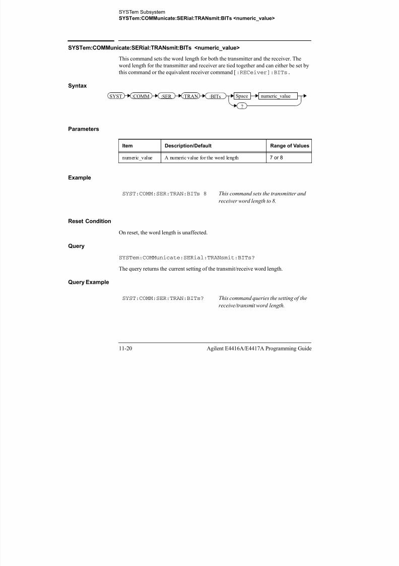
8/9/2019 E4416 Programming Guide
http://slidepdf.com/reader/full/e4416-programming-guide 452/615
Agilent E4416A/E4417A Programming Guide 11-21
This command turns echo mode on and off, allowing the power meter to be controlled
by a dumb terminal that may require its transmitted characters to be echoed. If ON is
specified, data received by the receiver is transmitted back to the sender (echo on). IfOFF is specified, data received by the receiver is not transmitted back to the sender
(echo off).
Syntax
Example
Reset Condition
On reset, the echo selection is unaffected.
Query
SYSTem:COMMunicate:SERial:TRANsmit:ECHO?
The query returns the current setting of the transmit/receive word length.
• ON is returned if the power meter is set to return received data back to the
sender (echo on).• OFF is returned if the power meter is not set to return received data back to
the sender (echo off).
Query Example
SYST:COMM:SER:TRAN:ECHO ON This command sets the power meter to
transmit any data received back to the
sender.
SYST:COMM:SER:TRAN:ECHO? This command queries whether or not
the power meter has been set to return
received data back to the sender.
SYST :COMM :SER :ECHO:TRAN Space
?
ON
OFF
SYSTem Subsystem
SYSTem:COMMunicate:SERial:TRANsmit:PACE XON|NONE
SYSTem:COMMunicate:SERial:TRANsmit:PACE XON|NONE

8/9/2019 E4416 Programming Guide
http://slidepdf.com/reader/full/e4416-programming-guide 453/615
11-22 Agilent E4416A/E4417A Programming Guide
This command enables (XON) and disables (NONE) an Xon/Xoff software handshake
for the transmitter. When enabled, if an Xoff control character is detected by the
receiver, the transmitter will not transmit further characters until an Xon controlcharacter is detected by the receiver.
Syntax
Example
Reset Condition
On reset, pacing is unaffected.
Query
SYSTem:COMMunicate:SERial:TRANsmit:PACE?
The query returns XON if the handshake is enabled and NONE if the handshake is
disabled.
Query Example
SYST:COMM:SER:TRAN:PACE XON This command enables the
transmitter Xon/Xoff software
handshake.
SYST:COMM:SER:TRAN:PACE? This command queries whether the
transmitter Xon/Xoff software
handshake is enabled ( XON ) or
disabled ( NONE ).
SYST :COMM :SER :PACE:TRAN Space
?
XON
NONE
SYSTem Subsystem
SYSTem:COMMunicate:SERial:TRANsmit:PARity[:TYPE] EVEN|ODD|ZERO|ONE|NONE
SYSTem:COMMunicate:SERial:TRANsmit:PARity[:TYPE] EVEN|ODD|ZERO|ONE|NONE

8/9/2019 E4416 Programming Guide
http://slidepdf.com/reader/full/e4416-programming-guide 454/615
Agilent E4416A/E4417A Programming Guide 11-23
This command decides what type of parity checking (if any) will take place on
received data and also decides what parity (if any) will be included with transmitted
data. The following choices are available and can be set using either this command orthe equivalent [:RECeive]:PARity[:TYPE] command.
Parity Type Description
EVEN The receiver expects a parity bit. All data received is
checked for even parity. An error is generated if this test
fails. Transmitted data includes a parity bit set for even
parity indication.
ODD The receiver expects a parity bit. All data received is
checked for odd parity. An error is generated if this test
fails. Transmitted data includes a parity bit set for odd
parity indication.
ZERO The receiver expects a parity bit. All data received has the
parity checked and if it is not a logic low an error will be
generated. Transmitted data includes a parity bit that is
always set low (stick 0 parity).
ONE The receiver expects a parity bit. All data received has the
parity checked and if it is not a logic high an error will be
generated. Transmitted data includes a parity bit that is
always set high (stick 1 parity).
NONE The receiver is not expecting a parity bit included in
received data and does not perform a parity check. The
transmitter does not include a parity bit in the transmitted
data.
SYSTem Subsystem
SYSTem:COMMunicate:SERial:TRANsmit:PARity[:TYPE] EVEN|ODD|ZE-
RO|ONE|NONE
Syntax
SYST :COMM :SER :PAR Space EVEN:TYPE:TRAN

8/9/2019 E4416 Programming Guide
http://slidepdf.com/reader/full/e4416-programming-guide 455/615
11-24 Agilent E4416A/E4417A Programming Guide
Example
Reset Condition
On reset, the parity selection is unaffected.
Query
SYSTem:COMMunicate:SERial:TRANsmit:PARity[:TYPE]?
The query returns the current setting of the transmit/receive parity type (EVEN, ODD,
ZERO, ONE or NONE).
Query Example
SYST:COMM:SER:TRAN:PAR ODD This command sets the transmitter to
include an odd parity bit in the
transmitted data and the receiver to
check for odd parity in the received
data.
SYST:COMM:SER:TRAN:PAR? This command queries what type of parity has been set on the
transmitted/received data.
SYST :CO :SER p
?
EVEN
ODD
ZERO
:TRAN
ONE
NONE
SYSTem Subsystem
SYSTem:COMMunicate:SERial:TRANsmit:SBITs <numeric_value>
SYSTem:COMMunicate:SERial:TRANsmit:SBITs <numeric_value>

8/9/2019 E4416 Programming Guide
http://slidepdf.com/reader/full/e4416-programming-guide 456/615
Agilent E4416A/E4417A Programming Guide 11-25
This command sets the number of stop bits expected by the receiver on received data
and the number of stop bits included by the transmitter in transmitted data.
Syntax
Parameters
Example
Reset Condition
On reset, the number of stop bits is unaffected.
Query
SYSTem:COMMunicate:SERial:TRANsmit:SBITs?The query returns the current setting of the transmit/receive stop bits.
Query Example
Item Description/Default Range of Values
numeric_value A numeric value for the number of stop bits. 1 or 2
SYST:COMM:SER:TRAN:SBIT 2 This command sets the number of stop
bits for the transmitter and receiver to2.
SYST:COMM:SER:TRAN:SBIT? This command queries the setting of the
receive/transmit stop bits.
SYST :COMM :SER :TRAN :SBIT Space numeric_value
?
SYSTem Subsystem
SYSTem:HELP:HEADers?
SYSTem:HELP:HEADers?
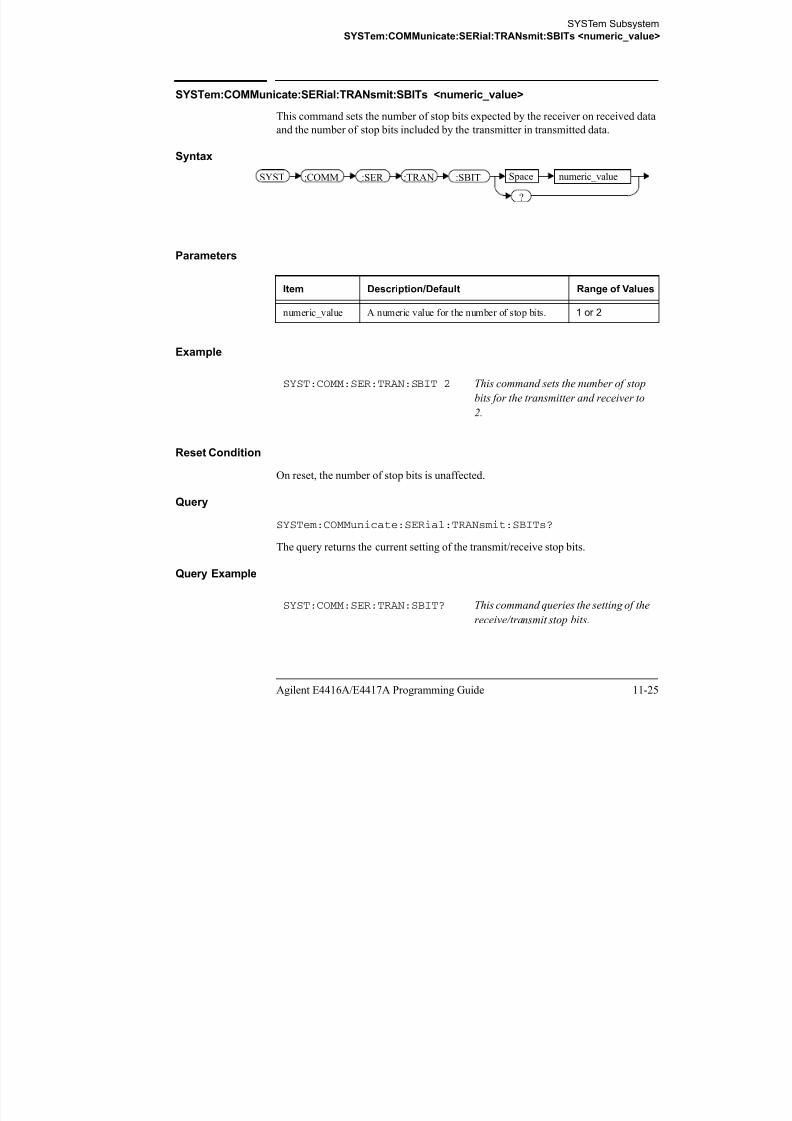
8/9/2019 E4416 Programming Guide
http://slidepdf.com/reader/full/e4416-programming-guide 457/615
11-26 Agilent E4416A/E4417A Programming Guide
This query returns a list of all SCPI commands supported by the instrument.
Data is returned in IEEE 488.2 arbitrary block program data format as follows:
Each point in the trace is represented as an IEEE 754 32 bit floating point number,
made up of four bytes in the data block. The MS byte is transmitted first. Each
complete block is terminated by a line feed.
Commands are listed in alphabetical order.
Syntax
Example
SYST:HELP:HEAD? This command returns the SCPI
commands supported by the instrument.
#xyyy..yddd................ddd<LF>
The number of y digits
Signifies the start of the block
The number of data bytes (d)
contained in the block.
Data bytes
Line feed character
signifies the end of the block
Example: if there are 12435 data bytes, y = 12435 and x = 5
SYST :HELP ?:HEAD
SYSTem Subsystem
SYStem:LOCal
SYStem:LOCal

8/9/2019 E4416 Programming Guide
http://slidepdf.com/reader/full/e4416-programming-guide 458/615
Agilent E4416A/E4417A Programming Guide 11-27
This command unlocks the front panel keypad and enables the power meter to be
controlled locally from the front panel. The power meter display status reporting line
will show “LCL”.
Syntax
Example
Error Messages
If this command is sent when the GPIB interface is selected, the error -113,
“Undefined header” occurs.
SYST:LOC This command unlocks the power meter
front panel keypad and enables local front panel control.
SYST :LOC
SYSTem Subsystem
SYSTem:PRESet <character_data>
SYSTem:PRESet <character_data>
Thi d t th t t l i t f i th

8/9/2019 E4416 Programming Guide
http://slidepdf.com/reader/full/e4416-programming-guide 459/615
11-28 Agilent E4416A/E4417A Programming Guide
This command presets the power meter to values appropriate for measuring the
communications format specified by <character_data>. The power meter is
preset to default values if no value or if the value DEFault is supplied.
Note DEFault settings apply to both *RST and to
SYSTem:PREset DEFault unless stated otherwise.
For further information on preset configurations, refer to
Tables 11-1 to 11-25.
Command results differ according to the sensor(s) connected to the power meter:
• If both an E9320 sensor and non-E9320 sensor are connected to a dual channel power meter, the channel connected to the E9320 sensor is set up according to the
<character_data> value and the non-E9320 channel is set to DEFault
values.
• If two E9320 sensors are connected to a dual channel power meter, both channels
are set to the same values except for bandwidth which is set to an appropriate value
for each sensor.
Primary and secondary channels
Dual channel meter channels are defined as either primary or secondary. The primarychannel is always the trigger master and primary channel measurements occupy a
greater share of the display space than secondary channel measurements.
• If a dual channel meter has one E9320 sensor connected, the E9320 sensor channel
is the primary channel. In such cases the primary channel could be either channel A
or channel B. The non-E9320 channel is the secondary channel.
• If a dual channel meter has two E9320 sensors connected to it, the primary channel
is always channel A and the secondary channel is channel B.
Syntax
SYST :PRES Space character_data
SYSTem Subsystem
SYSTem:PRESet <character_data>
Parameters
It D i ti /D f lt R f V l

8/9/2019 E4416 Programming Guide
http://slidepdf.com/reader/full/e4416-programming-guide 460/615
Agilent E4416A/E4417A Programming Guide 11-29
Example
Error messages
• If a non-E-Series power sensor or N8480 Series power sensor with Option CFT is
connected, the command can be used to set the power meter to Default settings.
When non-of the connected sensors is E9320 sensor, attempts to set the power
meter to any of the other settings result in error -241 “Hardware missing: E9320
Series sensor required” occurring.
• If BLUetooth or CDMAone is selected and an E9322/6A (1.5 MHz bandwidth) or
E9323/7A (5 MHz bandwidth) power sensor is not connected, error -241
“Hardware missing: Higher bandwidth E9320 sensor required on channel X.
Measurements on channel X may be inaccurate” occurs.
• If WCDMA or CDMA2000 is selected and an E9323/7A (5 MHz bandwidth)
power sensor is not connected, error -241 “Hardware missing: Higher bandwidth
E9320 sensor required on channel X. Measurements on channel X may be
inaccurate” occurs.
• If two E9320 power sensors are connected to a dual channel power meter and only
one is of sufficient bandwidth to support the selected format, error -241 “Hardware
missing: Higher bandwidth E9320 sensor required on channel X. Measurements on
channel X may be inaccurate” occurs.
Item Description/Default Range of Values
character_data A communications format which determines the
preset values. Refer to Tables 11.1 to 11.25 for
the preset values for each format.
DEfault
GSM900
EDGE
NADC
BLUetooth
CDMAone
WCDMA
CDMA2000
IDEN
SYST:PRES DEF This command presets the power meter with
default values. The same default values are set
when the parameter is omitted.
SYSTem SubsystemSYSTem:PRESet <character_data>
Preset Values
DEFault

8/9/2019 E4416 Programming Guide
http://slidepdf.com/reader/full/e4416-programming-guide 461/615
11-30 Agilent E4416A/E4417A Programming Guide
DEFault
The following table shows the power meter presets when <character_data> is
set to DEFault or omitted. Values are shown for all SCPI commands:
Table 0-1: DEFault: Power Meter Presets
Command Setting Comments
CALC[1]|2|3|4:FEED[1]|2 “POW:AVER” Select average measurement
type
CALC[1]|2|3|4:GAIN[:MAGN] 0.000 dB Display offset value
CALC[1]|2|3|4:GAIN:STAT OFF Display offset disabled
CALC[1]|2|3|4:LIM:CLE:AUTO ON Clear limit data at INIT
CALC[1]|2|3|4:LIM:LOW[:DATA] -90 dBm Lower limit
CALC[1]|2|3|4:LIM:STAT OFF Window limits checking disabled
CALC[1]|2|3|4:LIM:UPP[:DATA] +90 dBm
CALC[1]|2|3|4:MATH[:EXPR] Agilent E4416A:
Upper - channel A
Lower - channel A
Agilent E4417A
Upper - channel A
Lower - channel B
Math expression
CALC[1]|2|3|4:REL[:MAGN]:AUTO OFF Reference value disabled
CALC[1]|2|3|4:REL:STAT OFF Relative offset disabled
CAL[1]|2:ECON:STAT OFF TTL zero/calibration inputs
disabled
CAL[1]|2:RCAL not affected zero/cal lockout
CAL[1]|2:RCF 100.0% Reference calibration factor
DISP:CONT not affected Display contrast
DISP:ENAB ON Display enabled
DISP:SCR:FORM WIND Display format set to windowed
DISP[:WIND[1]|2]:ANAL:LOW -70 dBm Lower scale limit
DISP[:WIND[1]|2]:ANAL:UPP 20 dBm Upper scale limit
SYSTem SubsystemSYSTem:PRESet <character_data>
DISP[:WIND[1]|2]:FORM Agilent E4416A:
Upper digital
Display format
Command Setting Comments

8/9/2019 E4416 Programming Guide
http://slidepdf.com/reader/full/e4416-programming-guide 462/615
Agilent E4416A/E4417A Programming Guide 11-31
Upper - digital
Lower - analog
Agilent E4417A
Upper - digital
Lower - digital
DISP[:WIND[1]|2]:MET:LOW -70.000 dBm Analog meter lower limit
DISP[:WIND[1]|2]:MET:UPP +20.000 dBm Analog meter upper limit
DISP[:WIND[1]|2|][:NUM[1]|2]
:RES3 Window resolution
DISP[:WIND[1]|2]:SEL[1]|2 upper window Window selected
DISP[:WIND[1]|2][:STAT] ON Both windows enabled on
display
DISP[:WIND[1]|2]:TRAC:LOW DEF Maximum power
DISP[:WIND[1]|2]:TRAC:UPP DEF Minimum power
FORM[:READ]:BORD normal Binary order
FORM[:READ][:DATA] ascii Data format
INIT[1]|2:CONT *RST: OFF
SYS:PRES ON
Power Meter in idle state
Power Meter in wait for trigger
state
MEM:TABL:SEL not affected Active sensor calibration tableOUTP:REC[1]|2:FEED not affected Previous measurement
OUTP:REC[1]|2:LIM:LOW -150 dBm Minimum scaling value
OUTP:REC[1]|2:LIM:UPP 20 dBm Maximum scaling value
OUTP:ROSC:STAT OFF 50 MHz reference disabled
OUTP:TRIG:STAT OFF Trigger output signal disabled
OUTP:TTL[1]|2:ACT LOW TTL output active low
OUTP:TTL[1]|2:FEED “CALC[1]|2|3
|4:LIM:UPP”
TTL output represents upper
limit fail
OUTP:TTL[1]|2:STAT OFF TTL output is disabled
[SENS[1]]|SENS2:AVER:COUN 4 Filter length
[SENS[1]]|SENS2:AVER:COUN:AUTO ON Auto-filtering enabled
[SENS[1]]|SENS2:AVER:SDET 1 Step detection enabled
[SENS[1]]|SENS2:AVER[:STAT] ON Averaging enabled
[SENS[1]]|SENS2:AVER2:COUN 4 Video average length
[SENS[1]]|SENS2:AVER2[:STAT] ON Video averaging enabled
SYSTem SubsystemSYSTem:PRESet <character_data>
[SENS[1]]|SENS2:BAND|BWID:VID OFF Sensor video bandwidth set to
off
Command Setting Comments

8/9/2019 E4416 Programming Guide
http://slidepdf.com/reader/full/e4416-programming-guide 463/615
11-32 Agilent E4416A/E4417A Programming Guide
off
[SENS[1]]|SENS2:CORR:CFAC|
GAIN[1][:INPut][:MAGNitude]
100.0% Calibration factor
[SENS[1]]|SENS2:CORR:CSET[1]|
CSET2[:SEL]not affected Selected sensor calibration table
[SENS[1]]|SENS2:CORR:CSET[1]|
CSET2:STATnot affected Sensor calibration table disabled
[SENS[1]]|SENS2:CORR:DCYC|GAIN3
[:INP][:MAGN]1.000% Duty cycle factor
[SENS[1]]|SENS2:CORR:DCYC|GAIN3:STAT
OFF Duty cycle correction disabled
[SENS[1]]|SENS2:CORR:FDOF|GAIN4[:INP][:MAGN]
not affected Return frequency dependentoffset
[SENS[1]]|SENS2:CORR:GAIN2:STAT OFF Channel offset disabled
[SENS[1]]|SENS2:CORR:GAIN2:STAT
[:INPut][:MAGNitude]0.0 dB Enter channel offset value
[SENS[1]]|SENS2:DET:FUNC NORM Measurement mode
[SENS[1]]|SENS2:FREQ[:CW|:FIX] +50.000 MHz Frequency setting
[SENSe[1]]|SENS2:MRAT NORM Measurement speed
[SENS[1]]|SENS2:POW:AC:RANGupper Upper range selected
[SENS[1]]|SENS2:POW:AC:RANG:
AUTOON Auto-ranging selected
[SENS[1]]|SENS2:SPE 20 readings/
second
Speed
[SENS[1]]|SENS2:SWE[1]|2|3|4
:OFFS:TIME0 Set delay
[SENS[1]]|SENS2:SWE[1]|2|3|4
:TIMEGate 1: 100 us
Other gates: 0 sec
Set time gated period
[SENS[1]]|SENS2:TRACe:OFFSet: TIME 0 Delay
[SENS[1]]|SENS2:TRACe:TIME 100 us Duration of trace
[SENS[1]]|SENS2:V2P ATYP Select linearity correction
SYST:GPIB[:SELF]ADDR not affected Power meter address
SYST:COMM:SER:CONT:DTR not affected DTR signal line
SYST:COMM:SER:CONT:RTS not affected RTS signal line
SYST:COMM:SER[:REC]:BAUD not affected Baud rate
SYST:COMM:SER[:REC]:BITs not affected Word length
SYSTem SubsystemSYSTem:PRESet <character_data>
SYST:COMM:SER[:REC]:PACE not affected Xon/Xoff software handshake
SYST COMM SER[ REC] not affected Parity setting
Command Setting Comments

8/9/2019 E4416 Programming Guide
http://slidepdf.com/reader/full/e4416-programming-guide 464/615
Agilent E4416A/E4417A Programming Guide 11-33
SYST:COMM:SER[:REC]:PAR[:TYPE]
not affected Parity setting
SYST:COMM:SER[:REC]:SBIT not affected Number of stop bits
SYST:COMM:SER:TRAN:BAUD not affected Baud rate
SYST:COMM:SER:TRAN:BITs not affected Word length
SYST:COMM:SER:TRAN:ECHO not affected Dumb terminal control
SYST:COMM:SER:TRAN:PACE not affected Xon/Xoff software handshake
SYST:COMM:SER:TRAN:PAR[:TYPE]
not affected Parity setting
SYST:COMM:SER:TRAN:SBIT not affected Number of stop bits
TRAC[1]|2:STAT OFF Disable trace captureTRAC[1]|2:UNIT dBm Trace units
TRIG[1]|2:DEL:AUTO ON Insert settling time delay
TRIG[:SEQ]:DEL 0 Delay between recognition of
trigger event and start of a
measurement
TRIG[:SEQ]:HOLD 1 us Trigger holdoff
TRIG[:SEQ]:HYST 0 db Fall/rise below/above
TRIG:LEV
TRIG[:SEQ]:LEV 0 db Power level
TRIG[:SEQ]:LEV:AUTO ON Enable automatic setting of
trigger level
TRIG[:SEQ]:SLOP POS Trigger event recognized on
rising edge
TRIG[:SEQ[1]|2]:COUN 1 Trigger events for measurement
cycle
TRIG[:SEQ[1]|2]:DEL:AUTO ON Enable settling time delay
TRIG[:SEQ[1]|2]:SOUR IMM Trigger source set up
UNIT:POW dBm Power units
UNIT:POW:RAT dB Ratio units
SYSTem SubsystemSYSTem:PRESet <character_data>
GSM900
The following table shows the power meter presets when <character_data> is
set to GSM900.

8/9/2019 E4416 Programming Guide
http://slidepdf.com/reader/full/e4416-programming-guide 465/615
11-34 Agilent E4416A/E4417A Programming Guide
set to GSM900.
The GSM900 set-up provides the following:• Average power measurement in one GSM timeslot.
• Trace display showing “on” timeslot.
A GSM900 measurement is started by detecting the rising edge of a GSM RF
burst—for example the burst emitted by a GSM mobile—using the internal RF level
trigger. The trigger level is set to –20dBm. Time-gating is used to measure the
average power in the useful part of a GSM burst.
Commands not listed are preset according to their DEFault values (for further
information refer to Table 11-1).
Table 0-2: GSM900: Power Meter Presets
Command Setting Comments
Frequency
[SENS[1]]|SENS2:FREQ[:CW|:FIX] +900.000 MHz Frequency setting
Sensor measurement mode
[SENS[1]]|SENS2:DET:FUNC NORM Measurement mode
Sensor video bandwidth setup
[SENS[1]]|SENS2:BAND|BWID:VID E9321A/25A: HIGH
E9322A/26A: MED
E9323A/27A: LOW
Sensor video bandwidth
Gate setup
[SENS[1]]|SENS2:SWE[1]|2|3|4 :OFF:TIME
Gate 1: 20 us
Gates 2 - 4: 0
Delay between trigger point and
time gated period.
[SENS[1]]|SENS2:SWE[1]|2|3|4 :TIME
Gate 1: 520 us
Gates 2 - 4: 0
Length of time gated period for
time gated measurements.
Trigger setup
TRIG[:SEQ[1]|2]:SOUR INT1 Trigger source set up and
acquisition mode continuous
triggeringINIT:CONT ON
TRIG[:SEQ]:LEV:AUTO OFF Disable automatic setting of the
trigger level
TRIG[:SEQ]:LEV -20 dBm Power level
TRIG[:SEQ]:SLOP POS Trigger event recognized on the
rising edge of a signal
SYSTem SubsystemSYSTem:PRESet <character_data>
TRIG[:SEQ]:DEL 20 us Delay between recognition of
trigger event and start of a
Command Setting Comments

8/9/2019 E4416 Programming Guide
http://slidepdf.com/reader/full/e4416-programming-guide 466/615
Agilent E4416A/E4417A Programming Guide 11-35
Table 0-3: GSM900: Power Meter Presets: Window/Measurement Settings
gg
measurement
TRIG[:SEQ]:HOLD 4275 us Trigger holdoff
Step detection
[SENSe[1]]|SENS2:AVER:SDET 1 Step detection enabled
Trace setup
DISP[:WIND[1]|2]:TRAC:LOW +20 dBm Maximum power
DISP[:WIND[1]|2]:TRAC:UPP -35 dBm Minimum power
[SENS[1]]|SENS2:TRAC:OFFS :TIME <numeric_value>
-40 us Delay between delayed trigger
point and the start of the trace
[SENS[1]]|SENS2:TRAC:TIME<numeric_value>
700 us Length of the trace
FunctionSetting
No Sensor Non E9320 Sensor
Display setup
Upper window Channel A trace Primary channel1 trace
1. For further information refer to “Primary and secondary channels”, on page 11-28.
Lower window LU single numeric See Table 0-4
Window/measurement setup
Upper window/upper measurement (UU)
Feed N/A N/A
Measurement N/A N/A
Upper window/lower measurement (UL)
Feed N/A N/A
Measurement N/A N/A
Lower window/upper measurement (LU)
Feed Gate 1 Channel A Gate 1 primary channel1
Measurement Avg Avg
Lower window/lower measurement (LL)
Feed DEF See Table 0-4
Measurement DEF See Table 0-4
SYSTem SubsystemSYSTem:PRESet <character_data>
Table 0-4: GSM900: Power Meter Presets For Secondary Channel Sensors
FunctionSecondary Channel Sensor

8/9/2019 E4416 Programming Guide
http://slidepdf.com/reader/full/e4416-programming-guide 467/615
11-36 Agilent E4416A/E4417A Programming Guide
No Sensor Non E9320 Sensor E9320 Sensor
Display setup
Lower window LU single numeric Dual numeric Dual numeric
Lower window/lower measurement (LL)
Feed DEF Secondary channel1
1. For further information refer to “Primary and secondary channels”, on page 11-28.
Gate1 secondary
channel1 (channel B)
Measurement DEF Avg Avg
SYSTem SubsystemSYSTem:PRESet <character_data>
EDGE
EDGE (Enhanced Data for Global Evolution or Enhanced Data for GSM Evolution)
is an enhancement of the GSM standard. Whereas the GSM modulation scheme is

8/9/2019 E4416 Programming Guide
http://slidepdf.com/reader/full/e4416-programming-guide 468/615
Agilent E4416A/E4417A Programming Guide 11-37
GMSK which has constant amplitude, the EDGE modulation scheme is 8PSK which
has variable amplitude.
The EDGE set-up provides:
• Average power measurement in an EDGE burst.
• Peak-to-average ratio in an EDGE burst.
• A trace display of the burst profile
An EDGE measurement is started by detecting the rising edge of the EDGE RF
burst—for example the burst emitted by a mobile—using the internal RF level trigger.
The internal level trigger is set to –20dBm. Trigger level hysteresis is used to preventthe power meter re-triggering on the varying power levels within the EDGE burst.
Time-gating is used to measure the average power and the peak-to-average ratio in the
useful part of the RF burst.
The following table shows the power meter presets when <character_data> is
set to EDGE. Commands not listed are preset according to their DEFault values (for
further information refer to Table 11-1).
SYSTem SubsystemSYSTem:PRESet <character_data>
Table 0-5: EDGE: Power Meter Presets
Command Setting Comments
Frequency

8/9/2019 E4416 Programming Guide
http://slidepdf.com/reader/full/e4416-programming-guide 469/615
11-38 Agilent E4416A/E4417A Programming Guide
Frequency
[SENS[1]]|SENS2:FREQ[:CW|:FIX] +900.000 MHz Frequency settingSensor measurement mode
[SENS[1]]|SENS2:DET:FUNC NORM Measurement mode
Sensor video bandwidth setup
[SENS[1]]|SENS2:BAND|BWID:VID E9321A/25A: HIGH
E9322A/26A: MED
E9323A/27A: LOW
Sensor video bandwidth
Gate setup
[SENS[1]]|SENS2:SWE[1]|2|3|4
:OFF:TIME
Gate 1: 20 us
Gates 2 - 4: 0
Delay between trigger point and
time gated period.
[SENS[1]]|SENS2:SWE[1]|2|3|4 :TIME
Gate 1: 520 us
Gates 2 - 4: 0
Length of time gated period for
time gated measurements
Trigger setup
TRIGger[:SEQuence[1]|2]:SOUR INT1 Trigger source setup and
acquisition mode continuous
triggeringINIT:CONT ON
TRIG[:SEQ]:LEV:AUTO OFF Disable automatic setting of the
trigger level
TRIG[:SEQ]:LEV -20 dBm Power level
TRIG[:SEQ]:SLOP POS Trigger event recognized on the
rising edge of a signal
TRIG[:SEQ]:DEL 0 Delay between recognition of
trigger event and start of a
measurement
TRIG[:SEQ]:HOLD 4275 us Trigger holdoff
Step detection
[SENSe[1]]|SENS2:AVER:SDET 1 Step detection enabled
Trace setup
DISP[:WIND[1]|2]:TRAC:LOW +20 dBm Maximum power
DISP[:WIND[1]|2]:TRAC:UPP -35 dBm Minimum power
[SENS[1]]|SENS2:TRAC:OFFS :TIME <numeric_value>
-40 us Delay between delayed trigger
point and the start of the trace
[SENS[1]]|SENS2:TRAC:TIME<numeric_value>
700 us Length of the trace
SYSTem SubsystemSYSTem:PRESet <character_data>
Table 0-6: EDGE: Power Meter Presets: Window/Measurement Settings
FunctionSetting
No Sensor Non E9320 Sensor

8/9/2019 E4416 Programming Guide
http://slidepdf.com/reader/full/e4416-programming-guide 470/615
Agilent E4416A/E4417A Programming Guide 11-39
Table 0-7: EDGE: Power Meter Presets For Secondary Channel Sensors
No Sensor Non E9320 Sensor
Display setupUpper window Channel A trace Primary channel1 trace
1. For further information refer to “Primary and secondary channels”, on page 11-28.
Lower window Dual numeric See Table 0-7
Window/measurement setup
Upper window/upper measurement (UU)
Feed N/A N/A
Measurement N/A N/A
Upper window/lower measurement (UL)
Feed N/A N/A
Measurement N/A N/A
Lower window/upper measurement (LU)
Feed Gate 1 Channel A Gate 1 primary channel1
Measurement Avg Avg
Lower window/lower measurement (LL)
Feed Gate 1 Channel A See Table 0-7
Measurement Peak to avg See Table 0-7
FunctionSecondary Channel Sensor
No Sensor Non E9320 Sensor E9320 Sensor
Display setup
Lower window Dual numeric Dual numeric Dual numeric
Lower window/lower measurement (LL)
Feed Gate 1 primary channel1 Secondary channel1
1. For further information refer to “Primary and secondary channels”, on page 11-28.
Gate1 secondary
channel1 (channel B)
Measurement Peak to avg Avg Avg
SYSTem SubsystemSYSTem:PRESet <character_data>
NADC
The NADC set-up provides:
• Average power measurement of both active timeslots in NADC or IS-136

8/9/2019 E4416 Programming Guide
http://slidepdf.com/reader/full/e4416-programming-guide 471/615
11-40 Agilent E4416A/E4417A Programming Guide
“full rate” transmission. This assumes that there are two timeslots to be
measured in each frame as for example with timeslots 0 in the following
diagram:
Figure 0-1: A Trace Display Of The Active Timeslots
• A trace display of the active timeslots.
The measurement is started by detecting the RF burst—for example the burst emitted
by a mobile—using the internal RF level trigger. The internal level trigger is set to
–20dBm. Time-gating is used to measure the average power in two active timeslots
which are separated by two inactive timeslots
The following table shows the power meter presets when <character_data> is
set to NADC. Commands not listed are preset according to their DEFault values (for
further information refer to Table 11-1):
Table 0-8: NADC: Power Meter Presets
Command Setting Comments
Frequency
[SENS[1]]|SENS2:FREQ[:CW|:FIX] +800.000 MHz Frequency setting
Sensor measurement mode
[SENS[1]]|SENS2:DET:FUNC NORM Measurement mode
Sensor video bandwidth setup
[SENS[1]]|SENS2:BAND|BWID:VID E9321A/25A: OFF
E9322A/26A: OFF
E9323A/27A: OFF
Sensor video bandwidth
Gate setup
0 1 2 0 21
IS-136 full rate frame
SYSTem SubsystemSYSTem:PRESet <character_data>
[SENS[1]]|SENS2:SWE[1]|2|3|4 :OFF:TIME
Gate 1: 123.5 us
Gate 2: 20.123 ms
Gates 3 - 4: 0
Delay between trigger point
and time gated period.
Command Setting Comments

8/9/2019 E4416 Programming Guide
http://slidepdf.com/reader/full/e4416-programming-guide 472/615
Agilent E4416A/E4417A Programming Guide 11-41
Gates 3 4: 0
[SENS[1]]|SENS2:SWE[1]|2|3|4 :TIME
Gates 1 - 2: 6.46 ms Gates 3 - 4: 0
Length of time gated period fortime gated measurements.
Trigger setup
TRIG[:SEQ[1]|2]:SOUR INT1 Trigger source set up and
acquisition mode continuous
triggeringINIT:CONT ON
TRIG[:SEQ]:LEV:AUTO OFF Disable automatic setting of the
trigger level
TRIG[:SEQ]:LEV -20 dBm Power level
TRIG[:SEQ]:SLOP POS Trigger event recognized onthe rising edge of a signal
TRIG[:SEQ]:DEL 0 Delay between recognition of
trigger event and start of a
measurement
TRIG[:SEQ]:HOLD 30 ms Trigger holdoff
Step detection
[SENS[1]]|SENS2:AVER:SDET 0 Step detection disabled
Trace setup
DISP[:WIND[1]|2]:TRAC:LOW +20 dBm Maximum power
DISP[:WIND[1]|2]:TRAC:UPP -35 dBm Minimum power
[SENS[1]]|SENS2:TRAC:OFFS :TIME <numeric_value>
-0.2 ms Delay between delayed trigger
point and the start of the trace
[SENS[1]]|SENS2:TRAC:TIME<numeric_value>
-28 ms Length of the trace
SYSTem SubsystemSYSTem:PRESet <character_data>
Table 0-9: NADC: Power Meter Presets: Window/Measurement Settings
FunctionSetting
No Sensor Non E9320 Sensor

8/9/2019 E4416 Programming Guide
http://slidepdf.com/reader/full/e4416-programming-guide 473/615
11-42 Agilent E4416A/E4417A Programming Guide
Table 0-10: NADC: Power Meter Presets For Secondary Channel Sensors
Display setupUpper window Channel A trace Primary channel1 trace
1. For further information refer to “Primary and secondary channels”, on page 11-28.
Lower window Dual numeric See Table 0-10
Window/measurement setup
Upper window/upper measurement (UU)
Feed N/A N/A
Measurement N/A N/A
Upper window/lower measurement (UL)
Feed N/A N/A
Measurement N/A N/A
Lower window/upper measurement (LU)
Feed Gate 1 Channel A Gate 1 primary channel1
Measurement Avg Avg
Lower window/lower measurement (LL)
Feed Gate 2 Channel A See Table 0-10
Measurement Avg See Table 0-10
FunctionSecondary Channel Sensor
No Sensor Non E9320 Sensor E9320 Sensor
Display setup
Lower window Dual numeric Dual numeric Dual numeric Lower window/lower measurement (LL)
Feed Gate 2 primary channel1 Secondary channel1
1. For further information refer to “Primary and secondary channels”, on page 11-28.
Gate1 secondary
channel1 (channel B)
Measurement Avg Avg Avg
SYSTem SubsystemSYSTem:PRESet <character_data>
BLUetooth
The Bluetooth set-up provides:
• Average power in a Bluetooth DH1 data burst.
k i h b

8/9/2019 E4416 Programming Guide
http://slidepdf.com/reader/full/e4416-programming-guide 474/615
Agilent E4416A/E4417A Programming Guide 11-43
• Peak power in the same burst.
• Display of RF pulse in one timeslot.
The measurement is started by detecting the Bluetooth RF burst using the internal RF
level trigger. The internal trigger is set to –20dBm. Time-gating is used to measure
the peak and average power in a single Bluetooth DHI data burst which lasts for
366us. The DHI burst does not occupy a full Bluetooth timeslot, which lasts for
625us.
The following table shows the power meter presets when <character_data> is
set to BLUetooth. Commands not listed are preset according to their DEFault values (for further information refer to Table 11-1):
SYSTem SubsystemSYSTem:PRESet <character_data>
Table 0-11: BLUetooth: Power Meter Presets
Command Setting Comments
Frequency

8/9/2019 E4416 Programming Guide
http://slidepdf.com/reader/full/e4416-programming-guide 475/615
11-44 Agilent E4416A/E4417A Programming Guide
[SENS[1]]|SENS2:FREQ[:CW|:FIX] +2400.000 MHz Frequency settingSensor measurement mode
[SENS[1]]|SENS2:DET:FUNC NORM Measurement mode
Sensor video bandwidth setup
[SENS[1]]|SENS2:BAND|BWID:VID E9321A/25A: DEF
E9322A/26A: HIGH
E9323A/27A: MEDium
Sensor video bandwidth
Gate setup
[SENS[1]]|SENS2:SWE[1]|2|3|4
:OFF:TIME
Gate 1: 0.2 us
Gates 2 - 4: 0
Delay between trigger point
and time gated period.
[SENS[1]]|SENS2:SWE[1]|2|3|4 :TIME
Gate 1: 366 us
Gates 2 - 4: 0
Length of time gated period
for time gated measurements.
Trigger setup
TRIGger[:SEQuence[1]|2]:SOUR INT1 Trigger source set up and
acquisition mode continuous
triggeringINIT:CONT ON
TRIG[:SEQ]:LEV:AUTO OFF Disable automatic setting of
the trigger level
TRIG[:SEQ]:LEV -20 dBm Power level
TRIG[:SEQ]:SLOP POS Trigger event recognized on
the rising edge of a signal
TRIG[:SEQ]:DEL 0 Delay between recognition of
trigger event and start of a
measurement
TRIG[:SEQ]:HOLD 650 us Trigger holdoff
Step detection
[SENSe[1]]|SENS2:AVER:SDET 1 Step detection enabledTrace setup
DISP[:WIND[1]|2]:TRAC:LOW +20 dBm Maximum power
DISP[:WIND[1]|2]:TRAC:UPP -35 dBm Minimum power
[SENS[1]]|SENS2:TRAC:OFF :TIME <numeric_value>
-50 us Delay between delayed
trigger point and the start of
the trace
[SENS[1]]|SENS2:TRAC:TIME<numeric_value>
3.8 ms Length of the trace
SYSTem SubsystemSYSTem:PRESet <character_data>
Table 0-12: BLUetooth: Power Meter Presets: Window/Measurement Settings
FunctionSetting
No Sensor Non E9320 Sensor

8/9/2019 E4416 Programming Guide
http://slidepdf.com/reader/full/e4416-programming-guide 476/615
Agilent E4416A/E4417A Programming Guide 11-45
Table 0-13: BLUetooth: Power Meter Presets For Secondary Channel Sensors
Display setupUpper window Channel A trace Primary channel1 trace
1. For further information refer to “Primary and secondary channels”, on page 11-28.
Lower window Dual numeric See Table 0-13
Window/measurement setup
Upper window/upper measurement (UU)
Feed N/A N/A
Measurement N/A N/A
Upper window/lower measurement (UL)
Feed N/A N/A
Measurement N/A N/A
Lower window/upper measurement (LU)
Feed Gate 1 Channel A Gate 1 primary channel1
Measurement Avg Avg
Lower window/lower measurement (LL)
Feed Gate 1 Channel A See Table 0-13
Measurement Peak See Table 0-13
FunctionSecondary Channel Sensor
No Sensor Non E9320 Sensor E9320 Sensor
Display setup
Lower window Dual numeric Dual numeric Dual numeric Lower window/lower measurement (LL)
Feed Gate 1 primary channel1 Secondary channel1
1. For further information refer to “Primary and secondary channels”, on page 11-28.
Gate1 secondary
channel1 (channel B)
Measurement Peak Avg Avg
SYSTem SubsystemSYSTem:PRESet <character_data>
CDMAone
The cdmaOne set-up provides:
• Average power in an IS-95 cdmaOne signal (bandwidth is less than
1.5MHz).

8/9/2019 E4416 Programming Guide
http://slidepdf.com/reader/full/e4416-programming-guide 477/615
11-46 Agilent E4416A/E4417A Programming Guide
)
• Peak power and peak-to-average ratio of the signal over a defined,
statistically valid number of samples. The reading is continuously refreshed.
This gives an indication of how cdmaOne channel loading affects peak
power and power distribution.
The measurement is a continuously gated measurement on a cdmaOne signal. Its aim
is to measure the peak and average power corresponding to a <0.01% probability that
there are no peaks above the returned peak reading. Time gating is therefore set to
10ms, corresponding to 200000 samples. Triggering is set to occur continuously
internally to the meter. The internal trigger is set to AutoLevel. A reading over the10ms period is returned and the reading is then re-initiated for the next 10ms period.
In this way the reading always relates to a position beyond 0.01% on the CCDF curve
and will refresh to track any signal or DUT changes.
The following table shows the power meter presets when <character_data> is
set to CDMAone. Commands not listed are preset according to their DEFault
values (for further information refer to Table 11-1):
Table 0-14: CDMAone: Power Meter Presets
Command Setting Comments
Frequency
[SENS[1]]|SENS2:FREQ[:CW|:FIX] +850.000 MHz Frequency setting
Sensor measurement mode
[SENS[1]]|SENS2:DET:FUNC NORM Measurement mode
Sensor video bandwidth setup
[SENS[1]]|SENS2:BAND|BWID:VID E9321A/25A: DEF
E9322A/26A: HIGH
E9323A/27A: MEDium
Sensor video bandwidth
Gate setup
[SENS[1]]|SENS2:SWE[1]|2|3|4 :OFF:TIME
Gates 1 - 4: 0 Delay between trigger point
and time gated period.
[SENS[1]]|SENS2:SWE[1]|2|3|4 :TIME
Gate 1: 10 ms
Gates 2 - 4: 0
Length of time gated period
for time gated measurements.
Trigger setup
SYSTem SubsystemSYSTem:PRESet <character_data>
TRIGger[:SEQuence[1]|2]:SOUR INT1 Trigger source set up and
acquisition mode continuous
triggeringINIT:CONT ON
Command Setting Comments

8/9/2019 E4416 Programming Guide
http://slidepdf.com/reader/full/e4416-programming-guide 478/615
Agilent E4416A/E4417A Programming Guide 11-47
Table 0-15: CDMAone: Power Meter Presets: Window/Measurement Settings
TRIG[:SEQ]:LEV:AUTO ON Enable automatic setting ofthe trigger level
TRIG[:SEQ]:LEV Automatically
determined by power
meter
Power level
TRIG[:SEQ]:SLOP POS Trigger event recognized on
the rising edge of a signal
TRIG[:SEQ]:DEL 0 Delay between recognition of
trigger event and start of a
measurement
TRIG[:SEQ]:HOLD MIN Trigger holdoff
Step detection
[SENSe[1]]|SENS2:AVER:SDET 0 Step detection disabled
FunctionSetting
No Sensor Non E9320 Sensor Display setup
Upper window UU single numeric See Table 0-16
Lower window Dual numeric See Table 0-16
Window/measurement setup
Upper window/upper measurement (UU)
Feed Gate 1 channel A Gate 1 primary channel1
Measurement Avg Avg
Upper window/lower measurement (UL)
Feed DEF See Table 0-16
Measurement DEF See Table 0-16
Lower window/upper measurement (LU)
Feed Gate 1 Channel A See Table 0-16
Measurement Peak See Table 0-16
Lower window/lower measurement (LL)
Feed Gate 1 Channel A See Table 0-16
SYSTem SubsystemSYSTem:PRESet <character_data>
Measurement Peak to avg See Table 0-16
FunctionSetting
No Sensor Non E9320 Sensor
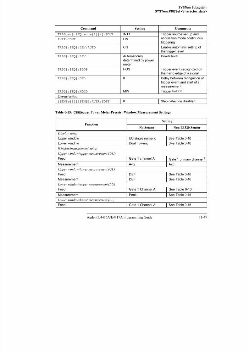
8/9/2019 E4416 Programming Guide
http://slidepdf.com/reader/full/e4416-programming-guide 479/615
11-48 Agilent E4416A/E4417A Programming Guide
Table 0-16: CDMAone: Power Meter Presets For Secondary Channel Sensors
1. For further information refer to “Primary and secondary channels”, on page 11-28.
FunctionSecondary Channel Sensor
No Sensor Non E9320 Sensor E9320 Sensor
Display setup
Upper window UU single numeric Dual numeric Dual numeric
Lower window Dual numeric Dual numeric Dual numeric
Upper window/lower measurement (UL)
Feed DEF Gate 1 primary channel1 Gate 1 primary
channel1 (channel A)
Measurement DEF Peak Peak
Lower window/upper measurement (LU)
Feed Gate 1 primary channel1 Gate 1 primary channel1 Gate 1 secondary
channel1 (channel B)
Measurement Peak Peak to avg Avg Lower window/lower measurement (LL)
Feed Gate 1 primary channel1 Secondary channel1
1. For further information refer to “Primary and secondary channels”, on page 11-28.
Gate1 secondary
channel1 (channel B)
Measurement Peak to avg Avg Peak to avg
SYSTem SubsystemSYSTem:PRESet <character_data>
WCDMA
The W-CDMA set-up provides:
• Average power in a W-CDMA signal (bandwidth <=5MHz)
• Peak power and peak-to-average ratio of the signal over a defined,

8/9/2019 E4416 Programming Guide
http://slidepdf.com/reader/full/e4416-programming-guide 480/615
Agilent E4416A/E4417A Programming Guide 11-49
statistically valid number of samples. The reading is continuously refreshed.
This indicates how W-CDMA channel loading affects peak power and power
distribution.
The measurement is a continuously gated measurement on a 3GPP W-CDMA signal.
Its aim is to measure the peak and average power corresponding to a <0.01%
probability that there are no peaks above the returned peak reading. Time gating is set
to 10ms, corresponding to 200000 samples. Triggering is set to occur continuously
internally to the meter. The internal trigger is set to AutoLevel. A reading over the
10ms period is returned then re-initiated for the next 10ms period. In this way the
reading always relates to a position beyond 0.01% on the CCDF curve and will
refresh to track any signal or DUT changes.
The following table shows the power meter presets when <character_data> is
set to WCDMA. Commands not listed are preset according to their DEFault values
(for further information refer to
Table 11-1):
Table 0-17: WCDMA : Power Meter Presets
Command Setting Comments
Frequency
[SENS[1]]|SENS2:FREQ[:CW|:FIX] +1900.000 MHz Frequency setting
Sensor measurement mode
[SENS[1]]|SENS2:DET:FUNC NORM Measurement mode
Sensor video bandwidth setup
[SENS[1]]|SENS2:BAND|BWID:VID E9321A/25A: DEF
E9322A/26A: DEF
E9323A/27A: HIGH
Sensor video bandwidth
Gate setup
[SENS[1]]|SENS2:SWE[1]|2|3|4 :OFF:TIME
Gates 1 -4: 0 Delay between trigger point
and time gated period.
[SENS[1]]|SENS2:SWE[1]|2|3|4 :TIME
Gate 1: 10 ms
Gates 2 - 4: 0
Length of time gated period
for time gated measurements.
Trigger setup
SYSTem SubsystemSYSTem:PRESet <character_data>
TRIGger[:SEQuence[1]|2]:SOUR INT1 Trigger source set up and
acquisition mode continuous
triggeringINIT:CONT ON
Command Setting Comments

8/9/2019 E4416 Programming Guide
http://slidepdf.com/reader/full/e4416-programming-guide 481/615
11-50 Agilent E4416A/E4417A Programming Guide
Table 0-18: WCDMA : Power Meter Presets: Window/Measurement Settings
TRIG[:SEQ]:LEV:AUTO ON Enable automatic setting ofthe trigger level
TRIG[:SEQ]:LEV Automatically
determined by power
meter
Power level
TRIG[:SEQ]:SLOP POS Trigger event recognized on
the rising edge of a signal
TRIG[:SEQ]:DEL 0 Delay between recognition of
trigger event and start of a
measurement
TRIG[:SEQ]:HOLD MIN Trigger holdoff
Step detection
[SENSe[1]]|SENS2:AVER:SDET 0 Step detection enabled
FunctionSetting
No Sensor Non E9320 Sensor Display setup
Upper window UU single numeric See Table 0-19
Lower window Dual numeric See Table 0-19
Window/measurement setup
Upper window/upper measurement (UU)
Feed Gate 1 channel A Gate 1 primary channel1
Measurement Avg Avg
Upper window/lower measurement (UL)
Feed DEF See Table 0-19
Measurement DEF See Table 0-19
Lower window/upper measurement (LU)
Feed Gate 1 Channel A See Table 0-19
Measurement Peak See Table 0-19
Lower window/lower measurement (LL)
Feed Gate 1 Channel A See Table 0-19
SYSTem SubsystemSYSTem:PRESet <character_data>
Measurement Peak to avg See Table 0-19
1. For further information refer to “Primary and secondary channels”, on page 11-28.
FunctionSetting
No Sensor Non E9320 Sensor

8/9/2019 E4416 Programming Guide
http://slidepdf.com/reader/full/e4416-programming-guide 482/615
Agilent E4416A/E4417A Programming Guide 11-51
Table 0-19: WCDMA : Power Meter Presets For Secondary Channel Sensors
FunctionSecondary Channel Sensor
No Sensor Non E9320 Sensor E9320 Sensor
Display setup
Upper window UU single numeric Dual numeric Dual numeric
Lower window Dual numeric Dual numeric Dual numericUpper window/lower measurement (UL)
Feed DEF Gate 1 primary channel1 Gate 1 primary
channel1 (channel A)
Measurement DEF Peak Peak
Lower window/upper measurement (LU)
Feed Gate 1 primary channel1 Gate 1 primary channel1 Gate 1 secondary
channel1 (channel B)
Measurement Peak Peak to avg Avg Lower window/lower measurement (LL)
Feed Gate 1 primary channel1 Secondary channel1
1. For further information refer to “Primary and secondary channels”, on page 11-28.
Gate1 secondary
channel1 (channel B)
Measurement Peak to avg Avg Peak to avg
SYSTem SubsystemSYSTem:PRESet <character_data>
CDMA2000
The cdma2000 set-up provides:
• Average power in a cdma2000 signal (bandwidth <=5MHz).
• Peak power and peak-to-average ratio of the signal over a defined,
statistically valid number of samples The reading is continuously refreshed

8/9/2019 E4416 Programming Guide
http://slidepdf.com/reader/full/e4416-programming-guide 483/615
11-52 Agilent E4416A/E4417A Programming Guide
statistically valid number of samples. The reading is continuously refreshed.
This indicates how cdma2000 channel loading affects peak power and power
distribution.
The measurement is a continuously gated measurement on a 3GPP cdma2000 signal.
Its aim is to measure the peak and average power corresponding to a <0.01%
probability that there are no peaks above the returned peak reading. Time gating is set
to 10ms, corresponding to 200,000 samples. Triggering is set to occur continuously
internally to the meter. The internal trigger is set to AutoLevel. A reading over the
10ms period is returned, then the reading is re-initiated for the next 10ms period. In
this way the reading always relates to a position beyond 0.01% on the CCDF curve
and will refresh to track any signal or DUT changes.
The following table shows the power meter presets when <character_data> is
set to CDMA2000. Commands not listed are preset according to their DEFault
values (for further information refer to Table 11-1):
Table 0-20: CDMA2000: Power Meter Presets
Command Setting Comments
Frequency
[SENS[1]]|SENS2:FREQ[:CW|:FIX] +1900.000 MHz Frequency setting
Sensor measurement mode
[SENS[1]]|SENS2:DET:FUNC NORM Measurement mode
Sensor video bandwidth setup
[SENS[1]]|SENS2:BAND|BWID:VID E9321A/25A: DEF
E9322A/26A: DEF
E9323A/27A: HIGH
Sensor video bandwidth
Gate setup
[SENS[1]]|SENS2:SWE[1]|2|3|4 :OFF:TIME
Gates 1 - 4: 0 Delay between trigger point
and time gated period.
[SENS[1]]|SENS2:SWE[1]|2|3|4 :TIME
Gate 1: 10 ms
Gates 2 - 4: 0
Length of time gated period
for time gated measurements.
Trigger setup
SYSTem SubsystemSYSTem:PRESet <character_data>
TRIGger[:SEQuence[1]|2]:SOUR INT1 Trigger source set up and
acquisition mode continuous
triggeringINIT:CONT ON
TRIG[:SEQ]:LEV:AUTO ON Enable automatic setting ofth t i l l
Command Setting Comments

8/9/2019 E4416 Programming Guide
http://slidepdf.com/reader/full/e4416-programming-guide 484/615
Agilent E4416A/E4417A Programming Guide 11-53
Table 0-21: CDMA2000: Power Meter Presets: Window/Measurement Settings
TRIG[:SEQ]:LEV:AUTO ON Enable automatic setting ofthe trigger level
TRIG[:SEQ]:LEV Automatically
determined by power
meter
Power level
TRIG[:SEQ]:SLOP POS Trigger event recognized on
the rising edge of a signal
TRIG[:SEQ]:DEL 0 Delay between recognition of
trigger event and start of a
measurement
TRIG[:SEQ]:HOLD MIN Trigger holdoff
Step detection
[SENSe[1]]|SENS2:AVER:SDET 0 Step detection disabled
FunctionSetting
No Sensor Non E9320 Sensor Display setup
Upper window UU single numeric UU single numeric
Lower window Dual numeric See Table 0-22
Window/measurement setup
Upper window/upper measurement (UU)
Feed Gate 1 channel A Gate 1 primary channel1
Measurement Avg Avg
Upper window/lower measurement (UL)Feed DEF DEF
Measurement DEF DEF
Lower window/upper measurement (LU)
Feed Gate 1 Channel AGate1 primary channel
1
Measurement Peak Peak
Lower window/lower measurement (LL)
Feed Gate 1 Channel A See Table 0-22

8/9/2019 E4416 Programming Guide
http://slidepdf.com/reader/full/e4416-programming-guide 485/615
SYSTem SubsystemSYSTem:PRESet <character_data>
IDEN
The iDEN set-up provides:
• Average power in one iDEN training and data pulse.
• Peak-to-average one iDEN training and data pulse.
• Average power in a 90ms iDEN frame

8/9/2019 E4416 Programming Guide
http://slidepdf.com/reader/full/e4416-programming-guide 486/615
Agilent E4416A/E4417A Programming Guide 11-55
• Average power in a 90ms iDEN frame.
The measurement is started by detecting the iDEN training burst—for example the
burst emitted by a mobile—using the internal RF level trigger. Time gating is used to
measure the average power in the following 15ms (data pulse). Gate 1 is used to
measure this data pulse. The 90ms frame is also captured to measure the average
power in the entire frame. Gate 2 is used to measure the 90ms frame.
The following table shows the power meter presets when <character_data> is
set to IDEN. Commands not listed are preset according to their DEFault values
(for further information refer to Table 11-1):
Table 0-23: iDEN : Power Meter Presets
Command Setting Comments
Frequency
[SENS[1]]|SENS2:FREQ[:CW|:FIX] +800.000 MHz Frequency setting
Sensor measurement mode
[SENS[1]]|SENS2:DET:FUNC NORM Measurement mode
Sensor video bandwidth setup
[SENS[1]]|SENS2:BAND|BWID:VID E9321A/25A: OFF
E9322A/26A: OFF
E9323A/27A: OFF
Sensor video bandwidth
Gate setup
[SENS[1]]|SENS2:SWE[1]|2|3|4 :OFF:TIME
Gate 1: 10 us
Gates 2 - 4: 0
Delay between trigger point
and time gated period.
[SENS[1]]|SENS2:SWE[1]|2|3|4
:TIME
Gate 1: 15 ms
Gate 2: 90 ms Gates 3 - 4: 0
Length of time gated period for
time gated measurements.
Trigger setup
TRIG[:SEQ[1]|2]:SOUR INT1 Trigger source set up and
acquisition mode continuous
triggeringINIT:CONT ON
TRIG[:SEQ]:LEV:AUTO OFF Disable automatic setting of the
trigger level
TRIG[:SEQ]:LEV -20 dBm Power level
SYSTem SubsystemSYSTem:PRESet <character_data>
TRIG[:SEQ]:SLOP POS Trigger event recognized on
the rising edge of a signal
TRIG[:SEQ]:DEL 0 Delay between recognition of
trigger event and start of a
measurement
Command Setting Comments

8/9/2019 E4416 Programming Guide
http://slidepdf.com/reader/full/e4416-programming-guide 487/615
11-56 Agilent E4416A/E4417A Programming Guide
Table 0-24: iDEN : Power Meter Presets: Window/Measurement Settings
measurement
TRIG[:SEQ]:HOLD 20 ms Trigger holdoff
Step detection
[SENSe[1]]|SENS2:AVER:SDET 1 Step detection enabled
Function
Setting
No Sensor Non E9320 Sensor
Display setup
Upper window UU single numeric See Table 0-25
Lower window Dual numeric See Table 0-25
Window/measurement setup
Upper window/upper measurement (UU)
Feed Gate 1 channel A Gate 1 primary channel1
1. For further information refer to “Primary and secondary channels”, on page 11-28.
Measurement Avg AvgUpper window/lower measurement (UL)
Feed DEF See Table 0-25
Measurement DEF See Table 0-25
Lower window/upper measurement (LU)
Feed Gate 1 Channel A See Table 0-25
Measurement Peak to avg See Table 0-25
Lower window/lower measurement (LL)
Feed Gate 2 Channel A See Table 0-25Measurement Avg See Table 0-25
SYSTem SubsystemSYSTem:PRESet <character_data>
Table 0-25: iDEN : Power Meter Presets For Secondary Channel Sensors
FunctionSecondary Channel Sensor
No Sensor Non E9320 Sensor E9320 Sensor
Display setupUpper window UU single numeric Dual numeric Dual numeric

8/9/2019 E4416 Programming Guide
http://slidepdf.com/reader/full/e4416-programming-guide 488/615
Agilent E4416A/E4417A Programming Guide 11-57
Upper window UU single numeric Dual numeric Dual numeric
Lower window Dual numeric Dual numeric Dual numeric
Upper window/lower measurement (UL)
Feed DEF Gate 1 primary channel1 Gate 1 primary
channel1 (channel A)
Measurement DEF Peak to Avg Peak to Avg
Lower window/upper measurement (LU)
Feed Gate 1 primary channel1
Gate 2 primary channel1
Gate 1 secondarychannel1 (channel B)
Measurement Peak to avg Avg Avg
Lower window/lower measurement (LL)
Feed Gate 2 primary channel1 Secondary channel1
1. For further information refer to “Primary and secondary channels”, on page 11-28.
Gate1 secondary
channel1 (channel B)
Measurement Avg Avg Avg
SYSTem Subsystem
SYSTem:REMote
SYSTem:REMote
This command locks the power meter front panel keypad excepting the Local key.
The power meter display status reporting line will show “RMT”. Local front panel
operation of the power meter is inhibited but can be enabled by pressing the Local
key.

8/9/2019 E4416 Programming Guide
http://slidepdf.com/reader/full/e4416-programming-guide 489/615
11-58 Agilent E4416A/E4417A Programming Guide
Syntax
Example
Error Messages
If this command is sent when the GPIB interface is selected, the error -113,
“Undefined header” occurs.
SYST:REM This command locks the power meter front panel keypad excepting the Local
key.
SYST :REM
SYSTem Subsystem
SYSTem:RINTerface GPIB|RS232|RS422
SYSTem:RINTerface GPIB|RS232|RS422
This command allows the remote control interface to be selected from GPIB, RS232,
and RS422.
Syntax

8/9/2019 E4416 Programming Guide
http://slidepdf.com/reader/full/e4416-programming-guide 490/615
Agilent E4416A/E4417A Programming Guide 11-59
Example
Query
SYSTem:RINTerface?
The query returns the current setting of the remote control interface (GPIB, RS232,
or RS422).
Query Example
SYST:RINT RS232 This command sets the power meter
remote control interface to RS232.
SYST:RINT? This command queries the current
setting of the remote control interface.
SYST :RINT Space
?
GPIB
RS232
RS422
SYSTem Subsystem
SYSTem:RWLock
SYSTem:RWLock
This command locks out the front panel keypad - including the front panel Local key.
The power meter display status reporting line will show “RMT”. In this state the
power meter cannot be returned to manual control from the front panel.
Syntax

8/9/2019 E4416 Programming Guide
http://slidepdf.com/reader/full/e4416-programming-guide 491/615
11-60 Agilent E4416A/E4417A Programming Guide
Syntax
Example
Error Messages
If this command is sent when the GPIB interface is selected, the error -113,
“Undefined header” occurs.
SYST:RWL This command locks the power meter
front panel keypad - including the Local key.
SYST :RWL
SYSTem Subsystem
SYSTem:VERSion?
SYSTem:VERSion?
This query returns the version of SCPI used in the power meter. The response is in the
form of XXXX.Y, where XXXX is the year and Y is the version number.
Syntax

8/9/2019 E4416 Programming Guide
http://slidepdf.com/reader/full/e4416-programming-guide 492/615
Agilent E4416A/E4417A Programming Guide 11-61
Example
SYST:VERS? This command queries which version of
SCPI is used in the power meter.
SYST :VERS ?
SYSTem Subsystem
SYSTem:VERSion?

8/9/2019 E4416 Programming Guide
http://slidepdf.com/reader/full/e4416-programming-guide 493/615
11-62 Agilent E4416A/E4417A Programming Guide
THIS PAGE HAS BEEN INTENTIONALLY LEFT BLANK.
12

8/9/2019 E4416 Programming Guide
http://slidepdf.com/reader/full/e4416-programming-guide 494/615
TRACe Subsystem
TRACe Subsystem
TRACe Subsystem
TRACe Subsystem
Note This command can only be used with E9320 Series sensors.
The TRACe subsystem is used to:
• Specify the type of trace to be captured.

8/9/2019 E4416 Programming Guide
http://slidepdf.com/reader/full/e4416-programming-guide 495/615
12-2 EPM-P Series Power Meters Programming Guide
p y yp p
• Enable/disable trace capture.
• Specify the trace units.
There are two pre-defined TRACE blocks:
• TRACe1: associated with channel A.
• TRACe2: associated with channel B.
The following commands are described in this chapter:
.
Keyword Parameter Form Notes Page
TRACe[1]|2[:DATA]? <character_data> [query only] page 12-3
:STATe <boolean> page 12-5
:UNIT <character_data> page 12-6
TRACe Subsystem
TRACe[1]|2[:DATA]? <character_data>
TRACe[1]|2[:DATA]? <character_data>
This query returns trace data from the specified channel. The trace resolution is
determined by <character_data>.
Note This command cannot be used over RS232 or RS422 serial interfaces.

8/9/2019 E4416 Programming Guide
http://slidepdf.com/reader/full/e4416-programming-guide 496/615
EPM-P Series Power Meters Programming Guide 12-3
Data is returned in IEEE 488.2 arbitrary block program data format as follows:
Each point in the trace is represented as an IEEE 754 32 bit floating point number,
made up of four bytes in the data block. The MS byte is transmitted first. Each
complete block is terminated by a line feed.
Note TRACe data formatting is not affected by FORMat subsystem formatting.
Syntax
#xyyy..yddd................ddd<LF>
The number of y digits
Signifies the start of the block
The number of data bytes (d)
contained in the block.
Data bytes
Line feed character
signifies the end of the block
Example: if there are 12435 data bytes, y = 12435 and x = 5
1
2
TRAC :DATA ? Space character_data
TRACe Subsystem
TRACe[1]|2[:DATA]? <character_data>
Parameters
Item Description/Default Range of Values
character_data • HRESolution: high resolution. The complete capture buffer
at the internal sample rate. The number of points in this trace is
determined by SENS:TRACe:TIMe.
• MRESolution: medium resolution A subset of the capture
HRES
MRESLRES

8/9/2019 E4416 Programming Guide
http://slidepdf.com/reader/full/e4416-programming-guide 497/615
12-4 EPM-P Series Power Meters Programming Guide
Example
Error Messages
If TRAC:STAT is off, the error -221, “Settings Conflict” occurs.
• MRESolution: medium resolution. A subset of the capture
buffer decimated to 1000 points.
• LRESolution: low resolution. A subset of the capture buffer,
decimated to the number of points required for the display. This
is really a way of outputting the same data used to generate the
graphical power display.
TRAC:DATA? HRES This command returns the trace data
for channel A at high resolution.
TRACe Subsystem
TRACe[1]|2:STATe <boolean>
TRACe[1]|2:STATe <boolean>
This command enables or disables trace capture for the specified channel.
Syntax
TRAC 0|OFFSpace:STAT1

8/9/2019 E4416 Programming Guide
http://slidepdf.com/reader/full/e4416-programming-guide 498/615
EPM-P Series Power Meters Programming Guide 12-5
Example
Reset Condition
On reset trace capture is set to OFF.
Query
TRACe[1]|2:STATe?
The query command enters a 1 or 0 into the output buffer indicating whether or not
trace capture is enabled or disabled.
• 1 is returned when trace capture is enabled.
• 0 is returned when trace capture is disabled.
Query Example
Error Messages
• If an E-Series E9320 sensor is not connected, error -241, “Hardware missing”
occurs.
• If an E-Series E9320 sensor is connected and set to AVERage mode rather than
NORMal mode, error –221, “Settings conflict” occurs.
TRAC2:STAT 1 This command enables trace capture
for channel B.
TRAC1:STAT? This command queries the current state
of trace capture for
channel A.
1|ON
?
2
TRACe Subsystem
TRACe[1]|2:UNIT <character_data>
TRACe[1]|2:UNIT <character_data>
This command sets the units for the trace for the specified channel
Note This command is included for compatibility purposes only. It has the same
purpose as[SENSe[1]]|SENSe2:TRACe:UNIT <character_data>
which should be used in preference

8/9/2019 E4416 Programming Guide
http://slidepdf.com/reader/full/e4416-programming-guide 499/615
12-6 EPM-P Series Power Meters Programming Guide
which should be used in preference.
Syntax
Parameters
Example
Reset Condition
On reset the units are set to dBm.
Query
TRACe[1]|2:UNIT?
The query command returns the current value of character_data.
Item Description/Default Range of Values
character_data • DBM: dBm.
• W: Watts.
DBM W
TRAC2:UNIT W This command sets the trace units for
channel B Watts.
TRAC :UNIT Space character_data
?
1
2
TRACe Subsystem
TRACe[1]|2:UNIT <character_data>
Query Example
TRAC2:UNIT? This command queries the current trace
units for channel B.

8/9/2019 E4416 Programming Guide
http://slidepdf.com/reader/full/e4416-programming-guide 500/615
EPM-P Series Power Meters Programming Guide 12-7
TRACe Subsystem
TRACe[1]|2:UNIT <character_data>

8/9/2019 E4416 Programming Guide
http://slidepdf.com/reader/full/e4416-programming-guide 501/615
12-8 EPM-P Series Power Meters Programming Guide
THIS PAGE HAS BEEN INTENTIONALLY LEFT BLANK.

8/9/2019 E4416 Programming Guide
http://slidepdf.com/reader/full/e4416-programming-guide 502/615
TRIGger Subsystem
TRIGger Subsystem
TRIGger Subsystem
The TRIGger subsystem is used to synchronize device actions with events. It
includes the ABORt, INITiate and TRIGger commands. These are all at the root
level in the command hierarchy but they are grouped here because of their close
functional relationship.Keyword Parameter Form Notes Page
ABORt[1]|2 [no query] page 13-3

8/9/2019 E4416 Programming Guide
http://slidepdf.com/reader/full/e4416-programming-guide 503/615
13-2 EPM-P Series Power Meters Programming Guide
Many of the above commands contain a numeric which represents a channel number.
For example TRIGger1 and TRIGger2 represent channel A and channel B
respectively. Channel B commands cannot be used with the single channel 4416A
power meter and result in the error “Header suffix out of range.”
ABORt[1]|2 [no query]
[non-SCPI]
page 13 3
INITiate[1]|2:CONTinuous <boolean> page 13-5
[:IMMediate] [no query] page 13-7
INITiate:CONTinuous
:ALL <boolean> page 13-8
:SEQuence[1]|2 <boolean> page 13-9
[:IMMediate]:ALL [no query] page 13-11
:SEQuence[1]|2 [no query] page 13-12
TRIGger[1]|2:DELay
:AUTO <boolean> page 13-14
[:IMMediate] [no query] page 13-16
:SOURce BUS|EXTernal|HOLD|IMMediate|INTernal[[1]|2]
page 13-17
TRIGger[:SEQuence]
:DELay <numeric_value> page 13-17:HOLDoff <numeric_value> page 13-21
:HYSTeresis <numeric_value> page 13-23
:LEVel <numeric_value> page 13-25
:AUTO <boolean> page 13-27
:SLOPe <character_data> page 13-29
[:SEQuence[1]|2]:COUNt <numeric_value> page 13-31
:DELay:AUTO <boolean> page 13-33
:IMMediate [no query] page 13-35
:SOURce BUS|EXTernal|HOLD|IMMediate|INTernal[[1]|2] page 13-36
TRIGger Subsystem
ABORt[1]|2]
ABORt[1]|2]
This command removes the specified channel from the wait for trigger state and
places it in the idle state. It does not affect any other settings of the trigger system.
When the INITiate command is sent, the trigger system responds as it did before
ABORt was executed.
If INITiate:CONTinuous is ON, then after ABORt the specified channel
immediately goes into the wait for trigger state.

8/9/2019 E4416 Programming Guide
http://slidepdf.com/reader/full/e4416-programming-guide 504/615
EPM-P Series Power Meters Programming Guide 13-3
y g gg
Syntax
Example
ABOR This command places channel A in the
idle state.
ABOR 1
2
TRIGger Subsystem
INITiate Commands
INITiate Commands
Initiate commands allow you to place the power meter in the wait for trigger state.
The INITiate commands are overlapped, that is, the power meter can continue
parsing and executing subsequent commands while initiated. Refer to IEEE 488.2,
section 12 for further details. Note that the pending operation flag is set when the power meter moves out of the idle state and is cleared when it re-enters the idle state.
Th f ll i d d ib d i thi ti

8/9/2019 E4416 Programming Guide
http://slidepdf.com/reader/full/e4416-programming-guide 505/615
13-4 EPM-P Series Power Meters Programming Guide
The following commands are described in this section:
INITiate[1]|2:CONTinuous <boolean>INITiate[1]|2[:IMMediate]INITiate:CONTinuous:ALL <boolean>INITiate:CONTinuous:SEQuence[1]|2 <boolean>INITiate[:IMMediate]:ALL
INITiate[:IMMediate]:SEQuence[1]|2
TRIGger Subsystem
INITiate[1]|2:CONTinuous <boolean>
INITiate[1]|2:CONTinuous <boolean>
This command sets the power meter for either a single trigger cycle or continuous
trigger cycles. A trigger cycle means that the power meter exits the wait for trigger
state and starts a measurement.
When entering local mode, if TRIGger[:SEQuence[1]|2]:SOURce is set toINT[[1]|2] or EXT, INITiate:CONTinuous is not changed. For other trigger
sources, INITiate:CONTinuous is set to ON.

8/9/2019 E4416 Programming Guide
http://slidepdf.com/reader/full/e4416-programming-guide 506/615
EPM-P Series Power Meters Programming Guide 13-5
If INITiate:CONTinuous is set to:
• OFF, the trigger system remains in the idle state until it is set to ON, or
INITiate:IMMediate is received. Once this trigger cycle is complete
the trigger system returns to the idle state.
• ON, the trigger system is initiated and exits the idle state. On completion of
each trigger cycle, the trigger system immediately commences anothertrigger cycle without entering the idle state.
Note This command performs the same function as
INITiate:CONTinuous:SEQuence[1]|2 <boolean>.
Syntax
Example
Reset Condition
On reset (*RST), this command is set to OFF.
On preset (SYSTem:PRESet) and instrument power-up, when entering local mode,
if TRIGger[:SEQuence[1]|2]:SOURce is set to INT[[1]|2] or EXT,
INIT2:CONT ON This command places channel B in the
wait for trigger state.
INIT 1
2
:CONT 0|OFF
1|ON
Space
?
TRIGger Subsystem
INITiate[1]|2:CONTinuous <boolean>
INITiate:CONTinuous is not changed. For other trigger sources,
INITiate:CONTinuous is set to ON.
Query
INITiate[1]|2:CONTinuous?
The query enters a 1 or 0 into the output buffer.
• 1 is returned when there is continuous triggering.

8/9/2019 E4416 Programming Guide
http://slidepdf.com/reader/full/e4416-programming-guide 507/615
13-6 EPM-P Series Power Meters Programming Guide
• 0 is returned when there is only a single trigger.
Query Example
INIT2:CONT? This command queries whether channel
B is set for single or continuous
triggering.
TRIGger Subsystem
INITiate[1]|2[:IMMediate]
INITiate[1]|2[:IMMediate]
This command sets the power meter in the wait for trigger state. When a trigger is
received, the measurement is taken and the result placed in the power meter memory.
If TRIGger:SOURce is set to IMMediate the measurement begins as soon as
INITiate:IMMediate is executed.
Use FETCh? to transfer a measurement from memory to the output buffer. Refer to
“FETCh[1]|2|3|4 Queries”, on page 2-21 for further details.

8/9/2019 E4416 Programming Guide
http://slidepdf.com/reader/full/e4416-programming-guide 508/615
EPM-P Series Power Meters Programming Guide 13-7
Note This command performs the same function as
INITiate:[IMMediate]:SEQuence[1]|2.
Syntax
Example
Error Messages
If the power meter is not in the idle state or INITiate:CONTinuous is ON, error
-213, “INIT ignored” occurs.
INIT2:IMM This command places channel B in the
wait for trigger state.
INIT :IMM1
2
TRIGger Subsystem
INITiate:CONTinuous:ALL <boolean>
INITiate:CONTinuous:ALL <boolean>
Sets all trigger sequences to be continuously initiated.
If INITiate:CONTinuous:ALL is set to:
• ON, trigger sequences are set to be continuously initiated.• OFF, trigger sequences are not set to be continuously initiated.
Syntax

8/9/2019 E4416 Programming Guide
http://slidepdf.com/reader/full/e4416-programming-guide 509/615
13-8 EPM-P Series Power Meters Programming Guide
Syntax
Example
Reset Condition
On reset (*RST), this command is set to OFF.
On preset (SYSTem:PRESet) and instrument power-up, when entering local mode,
if TRIGger[:SEQuence[1]|2]:SOURce is set to INT[[1]|2] or EXT,
INITiate:CONTinuous is not changed. For other trigger sources,
INITiate:CONTinuous is set to ON.
Query
INITiate:CONTinuous:ALL?
The query enters a 1 or 0 into the output buffer.
• 1 is returned when trigger sequences are set to be continuously initiated.
• 0 is returned when trigger sequences are not set to be continuously initiated.
Query Example
INIT:CONT:ALL ON This command sets all trigger
sequences to be continuously initiated.
INIT:CONT:ALL? This command queries whether both
channels are in a wait for trigger state.
INIT :CONT 0|OFF
1|ON
Space
?
:ALL
TRIGger Subsystem
INITiate:CONTinuous:SEQuence[1]|2 <boolean>
INITiate:CONTinuous:SEQuence[1]|2 <boolean>
This command sets the power meter for either a single trigger cycle or continuous
trigger cycles. A trigger cycle means that the power meter exits the wait for trigger
state and starts a measurement. When entering local mode,
INITiate:CONTinuous is set to ON.
If INITiate:CONTinuous:SEQuence[1|2] <boolean> is set to:
• OFF, the trigger system remains in the idle state until it is set to ON, or

8/9/2019 E4416 Programming Guide
http://slidepdf.com/reader/full/e4416-programming-guide 510/615
EPM-P Series Power Meters Programming Guide 13-9
INITiate:IMMediate is received. Once this trigger cycle is complete
the trigger system returns to the idle state.
• ON, the trigger system is initiated and exits the idle state. On completion of
each trigger cycle, the trigger system immediately commences another
trigger cycle without entering the idle state.
Note This command performs the same functions asINITiate[1]|2:CONTinuous <boolean>.
Syntax
Example
Reset Condition
On reset (*RST), this command is disabled.
On preset (SYSTem:PRESet) and instrument power-up, this command is enabled.
INIT:CONT:SEQ2 ON This command places channel B in a
wait for trigger state.
INIT :CONT 0|OFF
1|ON
Space
?
:SEQ 1
2
TRIGger Subsystem
INITiate:CONTinuous:SEQuence[1]|2 <boolean>
Query
INITiate[1]|2:CONTinuous:SEQuence?
The query enters a 1 or 0 into the output buffer.
• 1 is returned when there is continuous triggering.
• 0 is returned when there is only a single trigger.
Query Example

8/9/2019 E4416 Programming Guide
http://slidepdf.com/reader/full/e4416-programming-guide 511/615
13-10 EPM-P Series Power Meters Programming Guide
INIT2:CONT:SEQ? This command queries whether channel
B is set for single or continuous
triggering.

8/9/2019 E4416 Programming Guide
http://slidepdf.com/reader/full/e4416-programming-guide 512/615
TRIGger Subsystem
INITiate[:IMMediate]:SEQuence[1]|2
INITiate[:IMMediate]:SEQuence[1]|2
This command sets the power meter in the wait for trigger state. When a trigger is
received, the measurement is taken and the result placed in the power meter memory.
If TRIGger:SOURce is set to IMMediate the measurement begins as soon as
INITiate:IMMediate is executed.
Use FETCh? to transfer a measurement from memory to the output buffer. Refer to
FETCh1|2|3|4 in chapter 2 for further information.
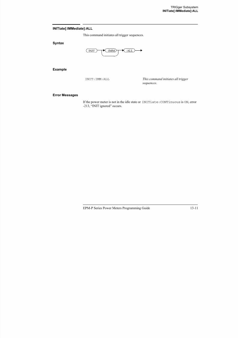
8/9/2019 E4416 Programming Guide
http://slidepdf.com/reader/full/e4416-programming-guide 513/615
13-12 EPM-P Series Power Meters Programming Guide
Note This command performs the same function as
INITiate[1]|2:[IMMediate].
Syntax
Example
Error Messages
If the power meter is not in the “idle” state or INITiate:CONTinuous is ON,
error -213, “INIT ignored” occurs.
INIT:IMM:SEQ1 This command places channel A in the
wait for trigger state.
INIT :IMM :SEQ 1
2
TRIGger Subsystem
TRIGger Commands
TRIGger Commands
TRIGger commands control the behavior of the trigger system.
The following commands are described in this section:
TRIGger[1]|2:DELay:AUTO <boolean>TRIGger[1]|2[:IMMediate]TRIGger[1]|2:SOURce BUS|IMMediate|HOLDTRIGger[:SEQuence]:DELay <numeric_value>TRIGger[:SEQuence]:HOLDoff <numeric value>

8/9/2019 E4416 Programming Guide
http://slidepdf.com/reader/full/e4416-programming-guide 514/615
EPM-P Series Power Meters Programming Guide 13-13
TRIGger[:SEQuence]:HOLDoff <numeric_value>TRIGger[:SEQuence]:HYSTeresis <numeric_value>TRIGger[:SEQuence]:LEVel <numeric_value>TRIGger[:SEQuence]:LEVel:AUTO <boolean>TRIGger[:SEQuence]:SLOPe <character_data>TRIGger[:SEQuence[1]|2]:COUNt <numeric_value>
TRIGger[:SEQuence[1]|2]:DELay:AUTO <boolean>TRIGger[:SEQuence[1]|2]:IMMediateTRIGger[:SEQuence[1]|2]:SOURce
BUS|EXTernal|HOLD|IMMediate|INTernal[[1]|2
TRIGger Subsystem
TRIGger[1]|2:DELay:AUTO <boolean>
TRIGger[1]|2:DELay:AUTO <boolean>
This command is used to determine whether or not there is a settling-time delay
before a measurement is made.
When this command is set to:
• ON, the power meter inserts a settling-time delay before taking the requested
measurement. This settling time allows the internal digital filter to be
updated with new values to produce valid, accurate measurement results.
The trigger with delay command allows settling time for the internal

8/9/2019 E4416 Programming Guide
http://slidepdf.com/reader/full/e4416-programming-guide 515/615
13-14 EPM-P Series Power Meters Programming Guide
gg y g
amplifiers and filters. It does not allow time for power sensor delay
In cases of large power changes, the delay may not be sufficient for complete
settling. Accurate readings can be assured by taking two successive
measurements for comparison.
• OFF, the power meter makes the measurement immediately a trigger isreceived.
TRIGger[1]|2:DELay:AUTO is ignored if TRIGger[1]|2[:IMMediate]
is set to ON.
Syntax
Example
Reset Condition
On reset, TRIGger:DELay:AUTO is set to ON.
TRIG:DEL:AUTO ON This command enables a delay on
channel A.
TRIG :AUTO:DEL 0|OFF
1|ON
Space
?
1
2
TRIGger Subsystem
TRIGger[1]|2:DELay:AUTO <boolean>
Query
TRIGger:DELay:AUTO?
The query enters a 1 or 0 into the output buffer indicating the status of
TRIGger:DELay:AUTO.
• 1 is returned when it is ON.• 0 is returned when it is OFF.

8/9/2019 E4416 Programming Guide
http://slidepdf.com/reader/full/e4416-programming-guide 516/615
EPM-P Series Power Meters Programming Guide 13-15
TRIGger Subsystem
TRIGger[1]|2[:IMMediate]
TRIGger[1]|2[:IMMediate]
This command causes a trigger to occur immediately, provided the specified channel
is in the wait for trigger state. When this command is executed, the measurement
result is stored in the power meter’s memory. Use FETCh? to place the measurement
result in the output buffer.
TRIGger[1]|2:DELay:AUTO is ignored if TRIGger[1]|2[:IMMediate]
is set to ON.
N t Thi d f h f i

8/9/2019 E4416 Programming Guide
http://slidepdf.com/reader/full/e4416-programming-guide 517/615
13-16 EPM-P Series Power Meters Programming Guide
Note This command performs the same function as
INITiate[1]|2:[IMMediate].
Syntax
Example
Error Messages
If the power meter is not in the wait for trigger state, then TRIGger:IMMediate
causes error -211, “Trigger ignored”.
TRIG This command causes a channel Atrigger to occur immediately.
TRIG :IMM1
2
TRIGger Subsystem
TRIGger[1]|2:SOURce BUS|EXTernal|HOLD|IMMediate|INTernal[[1]|2]
TRIGger[1]|2:SOURce BUS|EXTernal|HOLD|IMMediate|INTernal[[1]|2]
This command configures the trigger system to respond to the specified source. This
command only selects the trigger source. Use the INITiate command to place the
power meter in the wait for trigger state.
Note This command has been included for compatibility purposes. It has the same
purpose as TRIGger[:SEQuence[1]|2]:SOURceBUS|EXTernal|HOLD|IMMediate|INTernal[[1]|2] which should
be used in preference.

8/9/2019 E4416 Programming Guide
http://slidepdf.com/reader/full/e4416-programming-guide 518/615
EPM-P Series Power Meters Programming Guide 13-17
Syntax
Parameters
Item Description/Default Range of Values
source Available trigger sources:
• BUS: the trigger source is the group execute trigger <GET> bus command, a
*TRG common command or the TRIGGER:IMMediate SCPI command.
• EXTernal: the trigger source is the trigger input in the back panel.
• HOLD: triggering is suspended. The only way to trigger the power meter is to
use TRIGger:IMMediate.
• IMMediate: the trigger system is always true. If
INITiate:CONTinuous is ON the power meter is continually triggering
free (free run mode). If an INITiate:IMMediate command is sent a
measurement is triggered then the power meter returns to the idle state.
• INTernal: either INT1 (channel A) or INT2 (channel B).
BUS
EXTernal
HOLD
IMMediate
INTernal[[1]|2]
TRIG :SOUR 1
2
BUS
EXT
Space
HOLD
IMM
INT 1
2?
TRIGger Subsystem
TRIGger[1]|2:SOURce BUS|EXTernal|HOLD|IMMediate|INTernal[[1]|2]
Note The trigger source is set to IMMediate on instrument power-up and when
entering local mode.
The MEASure and CONFigure commands automatically set the trigger source
to IMMediate.
The READ? or MEASure commands should not be used if the trigger source is
set to BUS or HOLD.
E l

8/9/2019 E4416 Programming Guide
http://slidepdf.com/reader/full/e4416-programming-guide 519/615
13-18 EPM-P Series Power Meters Programming Guide
Example
Reset Condition
On reset, the trigger source is set to IMMediate.
Query
TRIGger:SOURce?
The query returns the current trigger source, either IMM, BUS or HOLD.
Query Example
Error Messages
• For dual channel power meters: if the master is changed to IMM, BUS or HOLD,
error -221 “Settings Conflict” occurs. In such situations the slave’s TRIG:SOUR must be changed so that it is no longer a slave.
• If the source is changed to INT1, INT2 or EXT and SENS:SPEED has a value of
200, error -221 “Settings Conflict” occurs.
• If the source is changed to INT1, INT2 or EXT and SENS:DET:FUNC is set to
AVERage, error -221 “Settings Conflict” occurs.
TRIG:SOUR IMM This command configures channel A for
immediate triggering.
TRIG:SOUR? This command queries channel A’s
trigger source.
TRIGger Subsystem
TRIGger[:SEQuence]:DELay <numeric_value>
TRIGger[:SEQuence]:DELay <numeric_value>
This command sets the delay between the recognition of a trigger event and the start
of a measurement.
Note The command is accepted forTRIGger[:SEQuence[1]]
(channel A) only,
for both single and dual channel power meters.
Syntax

8/9/2019 E4416 Programming Guide
http://slidepdf.com/reader/full/e4416-programming-guide 520/615
EPM-P Series Power Meters Programming Guide 13-19
Parameters
Example
Reset Condition
On reset, the trigger delay is set to 0 seconds.
Item Description/Default Range of Values
numeric_value The delay between the recognition of a
trigger event and the start of the
measurement.
• DEF: the default value is 0 seconds.
Units are resolved to 50 ns.
-1 to 1 seconds
DEF
TRIG:SEQ:DEL 0.001 This command sets a delay of 1 ms for
channel A.
:DEL Space
?
numeric_value
DEF
TRIG :SEQ
TRIGger Subsystem
TRIGger[:SEQuence]:DELay <numeric_value>
Query
TRIGger[:SEQuence]:DELay?
The query returns the current setting of the trigger delay.
Query Example
TRIG:SEQ:DEL? This command queries the trigger delay
of channel A.

8/9/2019 E4416 Programming Guide
http://slidepdf.com/reader/full/e4416-programming-guide 521/615
13-20 EPM-P Series Power Meters Programming Guide
Reset Condition
On reset, trigger delay is set to 0 seconds.
TRIGger Subsystem
TRIGger[:SEQuence]:HOLDoff <numeric_value>
TRIGger[:SEQuence]:HOLDoff <numeric_value>
This command sets the trigger holdoff in seconds.
Note The command is accepted for TRIGger[:SEQuence[1]] (channel A) only,
for both single and dual channel power meters.
Syntax
:HOLD Space numeric_valueTRIG :SEQ

8/9/2019 E4416 Programming Guide
http://slidepdf.com/reader/full/e4416-programming-guide 522/615
EPM-P Series Power Meters Programming Guide 13-21
Parameters
Example
Reset Condition
On reset the trigger holdoff is set to 1 us.
Item Description/Default Range of Values
numeric_value The trigger holdoff in seconds.
• DEF: the default value is 1 us.
• MIN: 1 us.
• MAX: 400 ms.
Units are resolved to 100 ns.
1 us to 0.4 seconds
DEF
MIN
MAX
TRIG:SEQ1:HOLD 0.1 This command sets the trigger holdoff
to 100 ms for channel A.
?
DEF
MIN
MAX
TRIGger Subsystem
TRIGger[:SEQuence]:HOLDoff <numeric_value>
Query
TRIGger[:SEQuence]:HOLDoff?
The query returns the current trigger holdoff setting.
Query Example
TRIG:SEQ:HOLD? This command queries the trigger
holdoff setting for channel A.

8/9/2019 E4416 Programming Guide
http://slidepdf.com/reader/full/e4416-programming-guide 523/615
13-22 EPM-P Series Power Meters Programming Guide
TRIGger Subsystem
TRIGger[:SEQuence]:HYSTeresis <numeric_value>
TRIGger[:SEQuence]:HYSTeresis <numeric_value>
This command sets:
• How far a signal must fall below TRIG:LEVel before a rising edge can be
detected.
• How far a signal must rise aboveTRIG:LEVel before a falling edge can bedetected.
Note The command is accepted for TRIGger[:SEQuence[1]] (channel A) only,
for both single and dual channel power meters.

8/9/2019 E4416 Programming Guide
http://slidepdf.com/reader/full/e4416-programming-guide 524/615
EPM-P Series Power Meters Programming Guide 13-23
Syntax
Example
Parameters
Reset Condition
On reset the value is set to 0 dB.
TRIG:SEQ:HYST 0.1 This command sets the value to
2 dB for channel A.
Item Description/Default Range of Values
numeric_value How far a signal must fall/rise before a
rising or falling edge can be detected.
DEF:the default value is 0 dB.
Units are resolved to 0.05 dB.
0 to 3 dB
DEF
:HYST Space numeric_value
?
DEF
TRIG :SEQ
TRIGger Subsystem
TRIGger[:SEQuence]:HYSTeresis <numeric_value>
Query
TRIGger[:SEQuence]:HYSTeresis?
The query returns the current value in dB.
Query Example
TRIG:SEQ:HYST? This command queries the value for
channel A.

8/9/2019 E4416 Programming Guide
http://slidepdf.com/reader/full/e4416-programming-guide 525/615
13-24 EPM-P Series Power Meters Programming Guide
TRIGger Subsystem
TRIGger[:SEQuence]:LEVel <numeric_value>
TRIGger[:SEQuence]:LEVel <numeric_value>
This command sets the power level at which a trigger event is recognized.
Note The command is accepted for TRIGger[:SEQuence[1]] (channel A) only,
for both single and dual channel power meters.
Syntax
:LEV Space numeric_valueTRIG :SEQ

8/9/2019 E4416 Programming Guide
http://slidepdf.com/reader/full/e4416-programming-guide 526/615
EPM-P Series Power Meters Programming Guide 13-25
Example
Parameters
Reset ConditionOn reset the power level is set to 0 dBm.
Query
TRIGger[:SEQuence]:LEVel?
The query returns the current power level setting.
TRIG:SEQ:LEV 10 This command sets the power level for
a trigger event to 10 dBm
Item Description/Default Range of Values
numeric_value The power level at which a trigger event is
recognized.
• DEF: the default value is 0 dBm.
Units are resolved to 0.1 dBm.
-40 to 20 dBm
DEF
?
DEF
TRIGger Subsystem
TRIGger[:SEQuence]:LEVel <numeric_value>
Query Example
TRIG:SEQ1:LEV? This command queries the power level
setting for channel A.

8/9/2019 E4416 Programming Guide
http://slidepdf.com/reader/full/e4416-programming-guide 527/615
13-26 EPM-P Series Power Meters Programming Guide
TRIGger Subsystem
TRIGger[:SEQuence]:LEVel:AUTO <boolean>
TRIGger[:SEQuence]:LEVel:AUTO <boolean>
This command enables/disables automatic setting of the trigger level.
When this command is set to:
• ON, automatic setting of the trigger level is enabled.
• OFF, automatic setting of the trigger level is disabled.
• ONCE, automatic setting of the trigger level is enabled for one trigger event
only. The value is then set to OFF.
Note The command is accepted for TRIGger[:SEQuence[1]] (channel A) only,
f b th i l d d l h l t

8/9/2019 E4416 Programming Guide
http://slidepdf.com/reader/full/e4416-programming-guide 528/615
EPM-P Series Power Meters Programming Guide 13-27
for both single and dual channel power meters.
Syntax
Example
Reset Condition
On reset the value is set to ON.
Query
TRIGger[:SEQuence]:LEVel:AUTO?
The query enters a 1 or 0 into the output buffer indicating the status of
TRIGger[:SEQuence]:LEVel:AUTO.
• 1 is returned when it is ON.
• 0 is returned when it is OFF.
TRIG:SEQ:LEV:AUTO 0 This command disables the automatic
setting of the trigger level for channel
A.
:LEV 0|OFF
1|ON
Space
?
:AUTOTRIG :SEQ
ONCE
TRIGger Subsystem
TRIGger[:SEQuence]:LEVel:AUTO <boolean>
Query Example
TRIG:SEQ:LEV:AUTO? This command queries the setting for
channel A.

8/9/2019 E4416 Programming Guide
http://slidepdf.com/reader/full/e4416-programming-guide 529/615
13-28 EPM-P Series Power Meters Programming Guide
TRIGger Subsystem
TRIGger[:SEQuence]:SLOPe <character_data>
TRIGger[:SEQuence]:SLOPe <character_data>
This command specifies whether a trigger event is recognized on the rising or falling
edge of a signal.
Note The command is accepted for TRIGger[:SEQuence[1]] (channel A) only,
for both single and dual channel power meters.
Syntax
:SLOP Space character_dataTRIG :SEQ

8/9/2019 E4416 Programming Guide
http://slidepdf.com/reader/full/e4416-programming-guide 530/615
EPM-P Series Power Meters Programming Guide 13-29
Parameters
Reset Condition
On reset the value is set to POSitive.
Query
TRIGger[:SEQuence]:SLOPe?
The query returns the current value of <character_data>.
Item Description/Default Range of Values
character_data How a trigger event is recognized:
• POSitive: a trigger event is
recognized on the rising edge of a signal.
• NEGative: a trigger event is
recognized on the falling edge of a
signal.
POSitive
NEGative
?
TRIGger Subsystem
TRIGger[:SEQuence]:SLOPe <character_data>
Query Example
TRIG:SEQ:SLOP? This command queries the current
value of <character_data> for
channel A.

8/9/2019 E4416 Programming Guide
http://slidepdf.com/reader/full/e4416-programming-guide 531/615
13-30 EPM-P Series Power Meters Programming Guide
TRIGger Subsystem
TRIGger[:SEQuence[1]|2]:COUNt <numeric_value>
TRIGger[:SEQuence[1]|2]:COUNt <numeric_value>
This command controls the path of the trigger subsystem in the upward traverse of the
wait for trigger state. COUNt loops through the event detection/measurement cycle
are performed. That is, COUNt measurements are performed in response to COUNt
trigger events.
COUNt can be set to a value >1 only when:
• [SENSe[1]]|SENSe2:MRATe <character_data> is set to FAST
and
• TRIGger[1]|2:SOURce set to BUS, IMMediate or HOLD.

8/9/2019 E4416 Programming Guide
http://slidepdf.com/reader/full/e4416-programming-guide 532/615
EPM-P Series Power Meters Programming Guide 13-31
|
Syntax
Parameters
Example
Reset Condition
On reset, the value is set to 1.
Item Description/Default Range of Values
numeric_value The number of triggered events for the
measurement cycle.
• DEF: the default value is 1.
1 to 50
DEF
TRIG:SEQ1:COUN 10 This command sets the number of
triggered events to 10 for the channel A
measurement cycle.
:COUN Space
?
numeric_value
DEF
TRIG :SEQ 1
2
TRIGger Subsystem
TRIGger[:SEQuence[1]|2]:COUNt <numeric_value>
Query
TRIGger[1]|2[:SEQuence[1]|2]:COUNt?
The query returns the current setting of trigger events for a specified channel.
Query Example
TRIG:SEQ2:COUN? This command queries the number of
triggered events for the channel B
measurement cycle.

8/9/2019 E4416 Programming Guide
http://slidepdf.com/reader/full/e4416-programming-guide 533/615
13-32 EPM-P Series Power Meters Programming Guide
Error Messages
If COUNt >1 when [SENSe[1]]|SENSe2:MRATe <character_data> is set
to NORMal or DOUBle, Error -221, “Settings Conflict” occurs.
TRIGger Subsystem
TRIGger[:SEQuence[1]|2]:DELay:AUTO <boolean>
TRIGger[:SEQuence[1]|2]:DELay:AUTO <boolean>
This command is used to determine whether or not there is a settling-time delay
before a measurement is made.
When this command is set to:
• ON, the power meter inserts a settling-time delay before taking the requestedmeasurement and for subsequent measurements. This settling time allows
the internal digital filter to be updated with new values to produce valid,
accurate measurement results. The trigger with delay command allows
settling time for the internal amplifiers and filters. It does not allow time for
power sensor delay.

8/9/2019 E4416 Programming Guide
http://slidepdf.com/reader/full/e4416-programming-guide 534/615
EPM-P Series Power Meters Programming Guide 13-33
In cases of large power changes, the delay may not be sufficient for complete
settling. Accurate readings can be assured by taking two successive
measurements for comparison.
• OFF, no settling-time delay is inserted and the power meter makes the
measurement immediately a trigger is received.
• ONCE, a settling-time delay is inserted before taking the requested
measurement, for one measurement only.
TRIGger[1]|2:DELay:AUTO is ignored if TRIGger[1]|2[:IMMediate]
is set to ON.
Syntax
Example
Reset Condition
On reset, TRIGger:DELay:AUTO is set to ON.
TRIG:SEQ:DEL:AUTO ON This command enables a delay on
channel A.
:DEL 0|OFF
1|ON
Space
?
:AUTO
ONCE
TRIG :SEQ 1
2
TRIGger Subsystem
TRIGger[:SEQuence[1]|2]:DELay:AUTO <boolean>
Query
TRIGger:DELay:AUTO?
The query enters a 1 or 0 into the output buffer indicating the status of
TRIGger:DELay:AUTO.
• 1 is returned when it is ON.
• 0 is returned when it is OFF.
Query Example
TRIG:SEQ2:DEL:AUTO? This command queries the settling-time
delay of channel B

8/9/2019 E4416 Programming Guide
http://slidepdf.com/reader/full/e4416-programming-guide 535/615
13-34 EPM-P Series Power Meters Programming Guide
delay of channel B.
TRIGger Subsystem
TRIGger[:SEQuence[1]|2]:IMMediate
TRIGger[:SEQuence[1]|2]:IMMediate
This command provides a one time over-ride of the normal process of the downward
path through the wait for trigger state. It causes the immediate exit of the event
detection layer if the trigger system is in this layer when the command is received. In
other words, the instrument stops waiting for a trigger and takes a measurement
ignoring any delay set by TRIG:DELay.
Syntax
:IMMTRIG :SEQ 1
2

8/9/2019 E4416 Programming Guide
http://slidepdf.com/reader/full/e4416-programming-guide 536/615
EPM-P Series Power Meters Programming Guide 13-35
Example
TRIG:SEQ:IMM This command initiates a measurement
on channel A.
TRIGger Subsystem
TRIGger[:SEQuence[1]|2]:SOURce BUS|EXTernal|HOLD|IMMediate|INTer-
TRIGger[:SEQuence[1]|2]:SOURce BUS|EXTernal|HOLD|IMMediate|INTernal[[1]|2]
This command configures the trigger system to respond to the specified source. This
command only selects the trigger source. Use the INITiate command to place the
power meter in the wait for trigger state.
Note This command has the same purpose as
TRIGger[1]|2:SOURceBUS|EXTernal|HOLD|IMMediate|INTernal[[1]|2]
Syntax

8/9/2019 E4416 Programming Guide
http://slidepdf.com/reader/full/e4416-programming-guide 537/615
13-36 EPM-P Series Power Meters Programming Guide
Parameters
Item Description/Default Range of Values
source Available trigger sources:
• BUS: the trigger source is the group execute trigger<GET> bus command, a
*TRG common command or the TRIGGER:IMMediate SCPI command.
• EXTernal: the trigger source is the trigger input in the back panel.
• HOLD: triggering is suspended. The only way to trigger the power meter is to
use TRIGger:IMMediate.
• IMMediate: the trigger system is always true. If
INITiate:CONTinuous is ON the power meter is continually triggering
free (free run mode). If an INITiate:IMMediate command is sent a
measurement is triggered then the power meter returns to the idle state.
• INTernal: either INT1 (channel A) or INT2 (channel B).
BUS
EXTernal
HOLD
IMMediate
INTernal[[1]|2]
:SOUR TRIG :SEQ 1
2
BUS
EXT
Space
HOLD
IMM
INT 1
2?
TRIGger Subsystem
TRIGger[:SEQuence[1]|2]:SOURce BUS|EXTernal|HOLD|IMMediate|INTer-
Note The trigger source is set to IMMediate on instrument power-up and when
entering local mode.
The MEASure and CONFigure commands automatically set the trigger source
to IMMediate.
The READ? or MEASure commands should not be used if the trigger source is
set to BUS or HOLD.
Example
TRIG:SOUR IMM This command configures channel A for

8/9/2019 E4416 Programming Guide
http://slidepdf.com/reader/full/e4416-programming-guide 538/615
EPM-P Series Power Meters Programming Guide 13-37
Reset Condition
On reset, the trigger source is set to IMMediate.
Query
TRIGger[:SEQuence[1]|2]:SOURce?
The query returns the current trigger source.
Query Example
Error Messages
• For dual channel power meters: if the master is changed to IMM, BUS or HOLD,
error -221 “Settings Conflict” occurs. In such situations the slave’s TRIG:SOUR must be changed so that it is no longer a slave.
• If the source is changed to INT1, INT2 or EXT and SENS:SPEED has a value of
200, error -221 “Settings Conflict” occurs.
• If the source is changed to INT1, INT2 or EXT and SENS:DET:FUNC is set to
AVERage, error -221 “Settings Conflict” occurs.
TRIG:SOUR IMM This command configures channel A for
immediate triggering.
TRIG:SEQ1:SOUR? This command queries the current
trigger source for channel A.
TRIGger Subsystem
TRIGger[:SEQuence[1]|2]:SOURce BUS|EXTernal|HOLD|IMMediate|INTer-

8/9/2019 E4416 Programming Guide
http://slidepdf.com/reader/full/e4416-programming-guide 539/615
13-38 EPM-P Series Power Meters Programming Guide
THIS PAGE HAS BEEN INTENTIONALLY LEFT BLANK.
14

8/9/2019 E4416 Programming Guide
http://slidepdf.com/reader/full/e4416-programming-guide 540/615
UNIT Subsystem
UNIT Subsystem
UNIT Subsystem
UNIT Subsystem
The UNIT command subsystem:
• Sets power measurement units to dBm or Watts.
• Sets measurement ratio units to dB or % (linear).
Both UNIT commands have a numeric suffix which determines whichwindow/measurement is set:
• UNIT1: units are set for the upper window/upper measurement.
• UNIT2: units are set for the lower window/upper measurement.
• UNIT3: units are set for the upper window/lower measurement.
• UNIT4: units are set for the lower window/lower measurement.

8/9/2019 E4416 Programming Guide
http://slidepdf.com/reader/full/e4416-programming-guide 541/615
14-2 EPM-P Series Power Meters Programming Guide
The following commands are described in this section:
The UNIT:POWer and UNIT:POWer:RATio commands are coupled as follows:
• If UNIT:POWer is set to dBm then UNIT:POWer:RATio is dB.• If UNIT:POWer is set to W then UNIT:POWer:RATio is %.
Keyword Parameter Form Notes Page
UNIT[1]|2|3|4:POWer <amplitude unit> page 14-3
:RATio <ratio_unit> [non-SCPI] page 14-6
UNIT Subsystem
UNIT[1]|2|3|4:POWer <amplitude_unit>
UNIT[1]|2|3|4:POWer <amplitude_unit>
This command sets the power measurement units for a specified
window/measurement. The power suffix set by UNIT:POWer is used for any
command which accepts a numeric value in more than one unit
For the E4416A:
• UNIT1:POWer sets the power measurement units for the upper
window/upper measurement.
• UNIT2:POWer sets the power measurement units for the lower
window/upper measurement.
• UNIT3:POWer sets the power measurement units for the upper
window/lower measurement.

8/9/2019 E4416 Programming Guide
http://slidepdf.com/reader/full/e4416-programming-guide 542/615
EPM-P Series Power Meters Programming Guide 14-3
• UNIT4:POWer sets the power measurement units for the lower
window/lower measurement.
For ratio and relative power measurements:
• If UNIT:POWer is W, the measurement units are percentage.
• If UNIT:POWer is DBM, the measurement units are dB relative.
Syntax
Parameters
Item Description/Default Range of Values
amplitude_unit The measurement unit.
• The default unit is dBm.
W
DBM
amplitude_unit:POW Space
?
UNIT 1
2
3
4
UNIT Subsystem
UNIT[1]|2|3|4:POWer <amplitude_unit>
Example
Reset Condition
On reset, all windows/measurements are set to DBM.
UNIT1:POW DBM This command sets the power
measurement units for the upper
window/upper measurement.

8/9/2019 E4416 Programming Guide
http://slidepdf.com/reader/full/e4416-programming-guide 543/615
14-4 EPM-P Series Power Meters Programming Guide
UNIT Subsystem
UNIT[1]|2|3|4:POWer <amplitude_unit>
Query
UNIT[1]|2|3|4:POWer?
The query returns the current setting of the power measurement units.
Query Example
UNIT2:POW? This command queries which
measurement units are being used on
the lower window/upper measurement.

8/9/2019 E4416 Programming Guide
http://slidepdf.com/reader/full/e4416-programming-guide 544/615
EPM-P Series Power Meters Programming Guide 14-5
UNIT Subsystem
UNIT[1]|2|3|4:POWer:RATio <ratio_unit>
UNIT[1]|2|3|4:POWer:RATio <ratio_unit>
This command sets the window/measurement ratio units.
• UNIT1:POWer:RATio sets the ratio measurement units for the upper
window/upper measurement.
• UNIT2:POWer:RATio sets the ratio measurement units for the lower
window/upper measurement.
• UNIT3:POWer:RATio sets the ratio measurement units for the upper
window/lower measurement.
• UNIT4:POWer:RATio sets the ratio measurement units for the lower
window/lower measurement.
Syntax

8/9/2019 E4416 Programming Guide
http://slidepdf.com/reader/full/e4416-programming-guide 545/615
14-6 EPM-P Series Power Meters Programming Guide
y
Parameters
Example
Reset Condition
On reset, the value is set to DB.
Item Description/Default Range of Values
ratio_unit The ratio measurement unit.
The default unit is DB.
DB
PCT
UNIT1:POW:RAT DB This command sets the ratio
measurement units for the upper
window/upper measurement.
:RAT:POW ratio_unitSpace
?
UNIT 1
2
3
4
UNIT Subsystem
UNIT[1]|2|3|4:POWer:RATio <ratio_unit>
Query
UNIT[1]|2|3|4]:POWer:RATio?
The query returns the current setting of the ratio measurement units.
Query Example
UNIT2:POW:RAT? This command queries which ratio
measurement units are being used on
the lower window/upper measurement.

8/9/2019 E4416 Programming Guide
http://slidepdf.com/reader/full/e4416-programming-guide 546/615
EPM-P Series Power Meters Programming Guide 14-7
UNIT Subsystem
UNIT[1]|2|3|4:POWer:RATio <ratio_unit>

8/9/2019 E4416 Programming Guide
http://slidepdf.com/reader/full/e4416-programming-guide 547/615
14-8 EPM-P Series Power Meters Programming Guide
THIS PAGE HAS BEEN INTENTIONALLY LEFT BLANK.
15

8/9/2019 E4416 Programming Guide
http://slidepdf.com/reader/full/e4416-programming-guide 548/615
SERVice Subsystem
SERVice Subsystem
SERVice Subsystem
SERVice Subsystem
The SERVice command subsystem is used to load information such as the power
meter processor board revision version and obtain information such as the serial
number of the current sensor(s) being used.
Keyword Parameter Form Notes Page
SERVice:BIST
:CALibrator <boolean> page 15-3
:FPATH[1]|2:MEASure? [query only]
:REFerence <numeric_value> [no query]
:STATe <boolean> [no query]
:TBASe:STATe <boolean> page 15-6
TRIG

8/9/2019 E4416 Programming Guide
http://slidepdf.com/reader/full/e4416-programming-guide 549/615
15-2 EPM-P Series Power Meters Programming Guide
:TRIG:LEVel
:STATe? [query only] page 15-8:TEST? [query only] page 15-9
:OPTion <character_data> page 15-10
:SENSor[1]|2:CALFactor <cal_factor_data> page 15-11
:CDATe? [query only] page 15-13
:CORRections:STATe <boolean> page 15-14
:CPLace? [query only] page 15-14
:FREQuency:MAXimum? [query only] page 15-17
:MINimum? [query only] page 15-18
:PCALfactor <cal_factor_data> page 15-19
:POWer:AVERage
:MAXimum? [query only] page 15-20
:PEAK:MAXimum? [query only] page 15-21
:USABle:MAXimum? [query only] page 15-22
:MINimum? [query only] page 15-23
:RADC? [query only] page 15-24
:SNUMber? [query only] page 15-25
:TNUMber? [query only] page 15-26:TYPE? [query only] page 15-27
:SNUMber <character_data> page 15-28
:VERSion:PROCessor <character_data> page 15-29
:SYSTem <character_data> page 15-30
SERVice Subsystem
SERVice:BIST:CALibrator <boolean>
SERVice:BIST:CALibrator <boolean>
This command enables/disables the calibrator self-test during power-up. It can be
used to disable the self-test if it incorrectly indicates failure—for example a long
sensor cable may cause an incorrect failure.
Syntax
:BISTSERV 0|OFF
1|ON
Space
?
:CAL
ONCE

8/9/2019 E4416 Programming Guide
http://slidepdf.com/reader/full/e4416-programming-guide 550/615
EPM-P Series Power Meters Programming Guide 15-3
Example
Reset Condition
On reset, the value is set to OFF.
Query
SERVice:BIST:CALibrator?
The query enters a 1 or 0 into the output buffer indicating the status of the self-test.
• 1 is returned when the self-test is enabled.
• 0 is returned when the self-test is disabled.
Query Example
SERV:BIST:CAL OFF This command disables the calibrator
self-test during power-up.
SERV:BIST:CAL? This command queries whether the self-test is enabled or disabled.
SERVice Subsystem
SERVice:BIST:FPATH[1]|2:MEASure?
SERVice:BIST:FPATH[1]|2:MEASure?
This query returns the power measured by the meter as a DC voltage, for the specified
channel. It applies to E9320 Series power sensors only.
Note Additional hardware is needed to run this command. For further information
refer to the power meter Service Guide.
Syntax
:BISTSERV ?:FPATH :MEAS1
2

8/9/2019 E4416 Programming Guide
http://slidepdf.com/reader/full/e4416-programming-guide 551/615
15-4 EPM-P Series Power Meters Programming Guide
Example
Error Messages
• If no power sensor is connected, error -241 “Hardware missing” occurs.
• If a non E9320 Series power sensor is connected, error -241
“Hardware missing” occurs.
• If FPATH2 is sent to a single channel meter, error -113
“Undefined header” occurs.
SERV:BIST:FPATH:MEAS? This command queries DC voltage
measured by the power meter on
channel A.
SERVice Subsystem
SERVice:BIST:FPATH[1]|2:REFerence <numeric_value>
SERVice:BIST:FPATH[1]|2:REFerence <numeric_value>
This command enters an externally measured sensor DC voltage at
0.0 dBm for use as a reference, for the specified channel. It applies to E9320 Series
power sensors only.
Note Additional hardware is needed to run this command. For further informationrefer to the power meter Service Guide.
Syntax
:BISTSERV :FPATH :REF numeric_valueSpace1
2

8/9/2019 E4416 Programming Guide
http://slidepdf.com/reader/full/e4416-programming-guide 552/615
EPM-P Series Power Meters Programming Guide 15-5
Parameters
Example
Reset Condition
On reset, the last entered value is retained.
Error Messages
• If no power sensor is connected, error -241 “Hardware missing” occurs.
• If a non E9320 Series power sensor is connected, error -241
“Hardware missing” occurs.
• If FPATH2 is sent to a single channel meter, error -113
“Undefined header” occurs.
Item Description/Default Range of Values
numeric_value An externally measured DC voltage when
0.0 dBm is applied to the sensor.
0.1 to 2.4 v
SERV:BIST:FPATH2:REF 1.2 This command enters an externally
measured sensor voltage of 1.2 v DC to
be used as a reference, for
channel B.
SERVice Subsystem
SERVice:BIST:FPATH[1]|2:STATe <boolean>
SERVice:BIST:FPATH[1]|2:STATe <boolean>
This command enables/disables fast path accuracy test mode for the specified
channel. It applies to E9320 Series power sensors only.
Note Additional hardware is needed to run this command. For further information
refer to the power meter Service Guide.
After using this command, a system preset is recommended.
If the command is set to:
• ON, fast path accuracy test mode is enabled for the specified channel.
• OFF, fast path accuracy test mode is disabled for the specified channel.

8/9/2019 E4416 Programming Guide
http://slidepdf.com/reader/full/e4416-programming-guide 553/615
15-6 EPM-P Series Power Meters Programming Guide
Syntax
Example
Reset Condition
On reset, test mode is disabled.
Error Messages
• If no power sensor is connected, error -241 “Hardware missing” occurs.
• If a non E9320 Series power sensor is connected, error -241“Hardware missing” occurs.
• If FPATH2 is sent to a single channel meter, error -113
“Undefined header” occurs.
SERV:BIST:FPATH:STATe OFF This command disables fast path
accuracy test mode for channel A.
:BISTSERV 0|OFF
1|ON
Space:FPATH :STATe1
2
SERVice Subsystem
SERVice:BIST:TBASe:STATe <boolean>
SERVice:BIST:TBASe:STATe <boolean>
This command sends a 10 MHz time base signal to the rear panel trig out for testing
purposes.
If the command is set to:
• ON, the 10 MHz time base signal is sent to the rear panel trigger out connector.• OFF, the 10 MHz time base signal is disabled.
Syntax
:BISTSERV 0|OFF
1|ON
Space
?
:TBASe :STATe

8/9/2019 E4416 Programming Guide
http://slidepdf.com/reader/full/e4416-programming-guide 554/615
EPM-P Series Power Meters Programming Guide 15-7
Example
Reset Condition
On reset, the signal is disabled.Query
SERVice:BIST:TBASe:STAT?
The query enters a 1 or 0 into the output buffer indicating the status of the 10 MHz
time base testing.
• 1 is returned when the signal is enabled.
• 0 is returned when the signal is disabled.
Query Example
SERV:BIST:TBAS:STAT OFF This command disables the signal.
SERV:BIST:TBASe:STAT? This command queries whether the test
is enabled or disabled.
?
SERVice Subsystem
SERVice:BIST:TRIGger:LEVel:STATe
SERVice:BIST:TRIGger:LEVel:STATe
This command queries trigger level.
• 1 is returned when the external trigger-in is high.
• 0 is returned when the external trigger-in is low.
Syntax
Example
SERV:BIST:TRIG:LEV:STAT? This command queries trigger level.
:BISTSERV :TRIG :LEVel :STATe ?

8/9/2019 E4416 Programming Guide
http://slidepdf.com/reader/full/e4416-programming-guide 555/615
15-8 EPM-P Series Power Meters Programming Guide
SERVice Subsystem
SERVice:BIST:TRIGger:TEST?
SERVice:BIST:TRIGger:TEST?
This command queries trigger in and out.
• 1 is returned if the test passes.
• 0 is returned if the test fails.
Note Before running this command, the read panel trigger out must be jumpered to therear panel trigger in.
Syntax
:BISTSERV :TRIG :TEST ?

8/9/2019 E4416 Programming Guide
http://slidepdf.com/reader/full/e4416-programming-guide 556/615
EPM-P Series Power Meters Programming Guide 15-9
Example
SERV:BIST:TRIG:TEST? This command queries trigger in and
out.
SERVice Subsystem
SERVice:OPTion <character_data>
SERVice:OPTion <character_data>
This command loads the power meter memory with the options fitted. The query form
of the command can be used to determine which options are fitted to the unit.
Syntax
Parameters
Item Description/Default Range of Values
character data Details the option number in a comma A to Z (uppercase)
SERV :OPT character_data
?
Space

8/9/2019 E4416 Programming Guide
http://slidepdf.com/reader/full/e4416-programming-guide 557/615
15-10 EPM-P Series Power Meters Programming Guide
Example
Query
SERVice:OPTion?
The query returns the current option string. For example, if the string “003” is
returned, the power meter is fitted with a sensor input and power reference on the back panel.
c c e _d e s e op o u be co
separated list. A maximum of 30 characterscan be used.
o (uppe c se)
a to z (lowercase)
0 - 9
_ (underscore)
SERV:OPT “002” This command loads the power meter
memory with 002 indicating that theunit is fitted with a rear panel sensor
input.
SERVice Subsystem
SERVice:SENSor[1]|2:CALFactor <cal_factor_data>
SERVice:SENSor[1]|2:CALFactor <cal_factor_data>
This command writes calibration factor data to, or reads calibration factor data from,
the currently connected sensor. The whole calibration factor block must be written at
once as a checksum is generated. The new block must not be larger than the existing
block.
This command applies to the following sensors:
• E4410 Series.
• N8480 Series (excluding Option CFT)
• E9300 Series.
• E9320 Series, average path data.
For E9320 Series sensors, peak path, refer to
SERVice:SENSor[1]|2:PCALFactor <cal_factor_data>.

8/9/2019 E4416 Programming Guide
http://slidepdf.com/reader/full/e4416-programming-guide 558/615
EPM-P Series Power Meters Programming Guide 15-11
Syntax
Parameters
Query
SERVice:SENSor[1]|2:CALFactor?
The query returns the current calibration factor block.
Query Example
Item Description/Default
cal_factor_data A binary data block. Refer to Appendix A
for further information.
SERV:SENS:CALF? This command returns the calibration
factor block for channel A.
SERV 1
2
:CALF:SENS cal_factor_data
?
Space
SERVice Subsystem
SERVice:SENSor[1]|2:CALFactor <cal_factor_data>
Error Messages
• If no power sensor is connected, error -241 “Hardware missing” occurs.
• If a non E-Series sensor or N8480 Series sensor with Option CFT is connected,
error -241 “Hardware missing” occurs.
• If an E9320 Series sensor is connected and
SERVice:SENSor[1]|2:CORRections:STATe is set to ON, error -221,
“Settings conflict” occurs.• If INIT:CONT is not set to OFF, error -221, “Settings conflict” occurs.

8/9/2019 E4416 Programming Guide
http://slidepdf.com/reader/full/e4416-programming-guide 559/615
15-12 EPM-P Series Power Meters Programming Guide
SERVice Subsystem
SERVice:SENSor[1]|2:CDATe?
SERVice:SENSor[1]|2:CDATe?
This query returns the calibration date in E-Series and N8480 Series sensors.
Calibration date information is stored in the sensor’s EEPROM.
Syntax
Example
SERV:SENS2:CDATe? This query returns the calibration date
SERV 1
2
:CDATe ?:SENS

8/9/2019 E4416 Programming Guide
http://slidepdf.com/reader/full/e4416-programming-guide 560/615
EPM-P Series Power Meters Programming Guide 15-13
Error Messages
• If no power sensor is connected, error -241 “Hardware missing” occurs.
• If a non E-Series N8480 Series sensor is connected, error -241 “Hardware missing”
occurs.
of the E-Series or N8480 Series sensorconnected to channel B.
SERVice Subsystem
SERVice:SENSor[1]|2:CORRections:STATe <boolean>
SERVice:SENSor[1]|2:CORRections:STATe <boolean>
This command enables/disables the voltage to corrected power conversion. It applies
to E9320 Series power sensors only.
Note Before setting this command to OFF, you must set the INIT:CONF command to
OFF.
After setting this command to OFF, you must only run commands relating to the
gathering of ADC values—for example, the SERV:SENS:RADC command.
Syntax
0|OFF
1|ON
Space:STAT:CORR SERV 1
2
:SENS

8/9/2019 E4416 Programming Guide
http://slidepdf.com/reader/full/e4416-programming-guide 561/615
15-14 EPM-P Series Power Meters Programming Guide
Example
Reset Condition
On reset, the value is set to OFF.
Query
SERVice:SENSor[1]|2:CORRections:STATe?
The query enters a 1 or 0 into the output buffer indicating the status of the voltage to
corrected power conversion.
• 1 is returned when voltage to corrected power conversion is enabled.
• 0 is returned when voltage to corrected power conversion is disabled.
SERV:SENS2:CORR:STAT ON This command enables the voltage to
corrected power conversion for
channel B.
1|ON
?
2
SERVice Subsystem
SERVice:SENSor[1]|2:CORRections:STATe <boolean>
Query Example
Error Messages
• If INIT:CONT is not set to off, error -221, “Settings conflict” occurs.
• If a non E9320 Series sensor is connected, error -241, “Hardware missing” occurs.
SERV:SENS:CORR:STAT? This command queries whether voltage
to corrected power conversion is
enabled for
channel A.

8/9/2019 E4416 Programming Guide
http://slidepdf.com/reader/full/e4416-programming-guide 562/615
EPM-P Series Power Meters Programming Guide 15-15
SERVice Subsystem
SERVice:SENSor[1]|2:CPLace?
SERVice:SENSor[1]|2:CPLace?
This query returns the calibration place in E-Series and N8480 Series sensors.
Calibration place information is stored in the sensor’s EEPROM.
Syntax
Example
SERV:SENS2:CPL? This query returns the place of
calibration of the E-Series or N8480
:CPL ?SERV 1
2
:SENS

8/9/2019 E4416 Programming Guide
http://slidepdf.com/reader/full/e4416-programming-guide 563/615
15-16 EPM-P Series Power Meters Programming Guide
Error Messages
• If no power sensor is connected, error -241 “Hardware missing” occurs.
• If a non E-Series or N8480 Series sensor is connected, error -241 “Hardware
missing” occurs.
calibration of the E Series or N8480
Series sensor connected to channel B.

8/9/2019 E4416 Programming Guide
http://slidepdf.com/reader/full/e4416-programming-guide 564/615
SERVice Subsystem
SERVice:SENSor[1]|2:FREQuency:MINimum?
SERVice:SENSor[1]|2:FREQuency:MINimum?
This query returns the minimum frequency that can be measured by the currently
connected sensor. It is applicable to E-Series sensors only. Minimum frequency
information is stored in the sensor’s EEPROM.
Syntax
Example
SERV:SENS1:FREQ:MIN? This query returns the minimum
:FREQ ?:MINSERV 1
2
:SENS

8/9/2019 E4416 Programming Guide
http://slidepdf.com/reader/full/e4416-programming-guide 565/615
15-18 EPM-P Series Power Meters Programming Guide
Error Messages
• If no sensor is connected, error -241, “Hardware missing” occurs.
• If a non E-Series is connected, error -241 “Hardware missing” occurs.
• If the E-Series sensor currently connected does not contain the necessary
information in EEPROM, error -241 “Hardware missing” occurs.
frequency that can be measured by the E-Series sensor currently connected to
channel A.
SERVice Subsystem
SERVice:SENSor[1]|2:PCALfactor <cal_factor_data>
SERVice:SENSor[1]|2:PCALfactor <cal_factor_data>
This command writes calibration factor data to, or reads calibration factor data from,
the currently connected sensor. The whole calibration factor block must be written at
once as a checksum is generated. The new block must not be larger than the existing
block.
This command applies to E9320 Series sensors for peak path data only. For E4410Series, E9300 Series, and E9320 Series sensors, average path data, refer to
SERVice:SENSor[1]|2:CALFactor <cal_factor_data>.
Syntax
P t
SERV 1
2
:PCALf :SENS cal_factor_data
?
Space

8/9/2019 E4416 Programming Guide
http://slidepdf.com/reader/full/e4416-programming-guide 566/615
EPM-P Series Power Meters Programming Guide 15-19
Parameters
Query
SERVice:SENSor[1]|2:PCALfactor?
The query returns the current peak path calibration factor block.
Query Example
Error Messages
• If no power sensor is connected, error -241 “Hardware missing” occurs.
• If a non E9320 Series sensor is connected, error -241
“Hardware missing” occurs.
• If INIT:CONT is not set to OFF, error -221, “Settings conflict” occurs.
Item Description/Default
cal_factor_data A binary data block. Refer to Appendix A
for further information.
SERV:SENS:PCALf? This command returns the peak path
calibration factor block for channel A.
SERVice Subsystem
SERVice:SENSor[1]|2:POWer:AVERage:MAXimum?
SERVice:SENSor[1]|2:POWer:AVERage:MAXimum?
This query returns the maximum average power that can be measured by the currently
connected sensor. It is applicable to E-Series sensors only. Maximum average power
information is stored in the sensor’s EEPROM.
Syntax
Example
SERV:SENS:POW:AVER:MAX? This query returns the maximum
th t b d b
:POW ?:AVER :MAXSERV 1
2
:SENS

8/9/2019 E4416 Programming Guide
http://slidepdf.com/reader/full/e4416-programming-guide 567/615
15-20 EPM-P Series Power Meters Programming Guide
Error Messages
• If no sensor is connected, error -241, “Hardware missing” occurs.
• If a non E-Series is connected, error -241 “Hardware missing” occurs.
• If the E-Series sensor currently connected does not contain the necessary
information in EEPROM, error -241 “Hardware missing” occurs.
average power that can be measured bythe E-Series sensor currently connected
to channel A.
SERVice Subsystem
SERVice:SENSor[1]|2:POWer:PEAK:MAXimum?
SERVice:SENSor[1]|2:POWer:PEAK:MAXimum?
This query returns the maximum peak power that can be measured by the currently
connected sensor. It is applicable to E-Series sensors only. Maximum peak power
information is stored in the sensor’s EEPROM.
Syntax
Example
SERV:SENS2:POW:PEAK:MAX? This query returns the maximum peak
power that can be measured by the
:POW ?:PEAK :MAXSERV 1
2
:SENS

8/9/2019 E4416 Programming Guide
http://slidepdf.com/reader/full/e4416-programming-guide 568/615
EPM-P Series Power Meters Programming Guide 15-21
Error Messages
• If no sensor is connected, error -241, “Hardware missing” occurs.
• If a non E-Series is connected, error -241 “Hardware missing” occurs.
• If the E-Series sensor currently connected does not contain the necessaryinformation in EEPROM, error -241 “Hardware missing” occurs.
power that can be measured by the E-Series sensor currently connected to
channel B.
SERVice Subsystem
SERVice:SENSor[1]|2:POWer:USABle:MAXimum?
SERVice:SENSor[1]|2:POWer:USABle:MAXimum?
This query returns the maximum power that can be accurately measured by the
currently connected sensor. It is applicable to E-Series sensors only. Maximum power
information is stored in the sensor’s EEPROM.
Syntax
Example
SERV:SENS1:POW:USAB:MAX? This query returns the maximum power
that can be accurately measured by the
E S i tl t d t
:POW ?:USAB :MAXSERV 1
2
:SENS
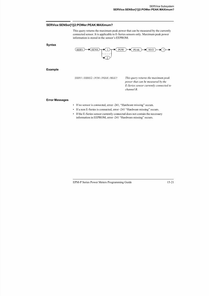
8/9/2019 E4416 Programming Guide
http://slidepdf.com/reader/full/e4416-programming-guide 569/615
15-22 EPM-P Series Power Meters Programming Guide
Error Messages
• If no sensor is connected, error -241, “Hardware missing” occurs.
• If a non E-Series is connected, error -241 “Hardware missing” occurs.
• If the E-Series sensor currently connected does not contain the necessary
information in EEPROM, error -241 “Hardware missing” occurs.
E-Series sensor currently connected to
channel A.
SERVice Subsystem
SERVice:SENSor[1]|2:POWer:USABle:MINimum?
SERVice:SENSor[1]|2:POWer:USABle:MINimum?
This query returns the minimum power that can be accurately measured by the
currently connected sensor. It is applicable to E-Series sensors only. Maximum power
information is stored in the sensor’s EEPROM.
Syntax
Example
SERV:SENS:POW:USAB:MIN? This query returns the minimum power
that can be accurately measured by the
E Series sensor currently connected to
:POW ?:USAB :MINSERV 1
2
:SENS

8/9/2019 E4416 Programming Guide
http://slidepdf.com/reader/full/e4416-programming-guide 570/615
EPM-P Series Power Meters Programming Guide 15-23
Error Messages
• If no sensor is connected, error -241, “Hardware missing” occurs.
• If a non E-Series is connected, error -241 “Hardware missing” occurs.
• If the E-Series sensor currently connected does not contain the necessary
information in EEPROM, error -241 “Hardware missing” occurs.
E-Series sensor currently connected to
channel A.
SERVice Subsystem
SERVice:SENSor[1]|2:RADC?
SERVice:SENSor[1]|2:RADC?
This query returns a new raw uncorrected measurement in volts, as a
32 bit signed integer.
Note For E9320 Series sensors:
before running this query, the voltage to corrected power conversion must be
disabled using the SERVice:SENSor[1]|2:CORRections:STATe command.
Syntax
:RADC ?SERV 1
2
:SENS

8/9/2019 E4416 Programming Guide
http://slidepdf.com/reader/full/e4416-programming-guide 571/615
15-24 EPM-P Series Power Meters Programming Guide
Example
Error Messages
• If INIT:CONT is set to ON, error -221 “Settings Conflict” occurs.
• If an E9320 Series sensor is connected and
SERVice:SENSor[1]|2:CORRections:STATe is set to ON, error -221
“Settings Conflict” occurs.
SERV:SENS2:RADC? This query returns a new raw
uncorrected measurement for the
sensor connected to channel B.
SERVice Subsystem
SERVice:SENSor[1]|2:SNUMber?
SERVice:SENSor[1]|2:SNUMber?
This query returns the serial number for E-Series and N8480 Series sensors. Serial
number information is stored in the sensor’s EEPROM.
Syntax
Example
SERV:SENS2:SNUM? This query returns the serial number of
the E-Series or N8480 Series sensor
connected to channel B.
:SNUM ?SERV 1
2
:SENS

8/9/2019 E4416 Programming Guide
http://slidepdf.com/reader/full/e4416-programming-guide 572/615
EPM-P Series Power Meters Programming Guide 15-25
Error Messages
• If no sensor is connected, error -241, “Hardware missing” occurs.
• If a non E-Series or N8480 Series sensor is connected, error -241 “Hardware
missing” occurs.
SERVice Subsystem
SERVice:SENSor[1]|2:TNUMber?
SERVice:SENSor[1]|2:TNUMber?
This query returns the tracking number for E-Series sensors. Tracking number
information is stored in the sensor’s EEPROM.
Syntax
Example
SERV:SENS2:TNUM? This query returns the serial number of
the E-Series sensor connected to
channel B.
:TNUM ?SERV 1
2
:SENS

8/9/2019 E4416 Programming Guide
http://slidepdf.com/reader/full/e4416-programming-guide 573/615
15-26 EPM-P Series Power Meters Programming Guide
Error Messages
• If no sensor is connected, error -241, “Hardware missing” occurs.
• If a non E-Series sensor is connected, error -241 “Hardware missing” occurs.
SERVice Subsystem
SERVice:SENSor[1]|2:TYPE?
SERVice:SENSor[1]|2:TYPE?
This query identifies the sensor type connected to the power meter input channel(s).
For Agilent 8480 Series sensors, either “A”, “B”, “D”, or “H” is returned. For
E-Series and N8480 Series sensors, the model number stored in EEPROM is returned
Syntax
Example
SERV:SENS2:TYPE? This query returns either, “A”, “B”,
“D”, or “H” if an Agilent 8480 Series
:TYPE ?SERV 1
2
:SENS

8/9/2019 E4416 Programming Guide
http://slidepdf.com/reader/full/e4416-programming-guide 574/615
EPM-P Series Power Meters Programming Guide 15-27
Error Messages
• If no sensor is connected, error -241, “Hardware missing” occurs.
sensor is connected to channel B, or the
sensor model number if an E-Series or
N8480 Series sensor is connected to
channel B.
SERVice Subsystem
SERVice:SNUMber <character_data>
SERVice:SNUMber <character_data>
This command loads the power meter with a serial number in the form GB12345678
or US12345678.
Syntax
Parameters
Item Description/Default Range of Values
character_data Details the power meter serial number in the
form GB12345678 or US12345678. A
maximum of 30 characters can be used.
A to Z (uppercase)
a to z (lowercase)0 - 9
SERV :SNUM character_dataSpace
?

8/9/2019 E4416 Programming Guide
http://slidepdf.com/reader/full/e4416-programming-guide 575/615
15-28 EPM-P Series Power Meters Programming Guide
Example
Query
SERVice:SNUMber?
The query returns the power meter serial number in the form GB12345678 or
US12345678.
0 - 9
SERV:SNUM GB12345678 This command loads the power meter
with the serial number GB12345678.
SERVice Subsystem
SERVice:VERSion:PROCessor <character_data>
SERVice:VERSion:PROCessor <character_data>
This command loads the power meter with the processor board revision version.
Syntax
Parameters
Item Description/Default Range of Values
character_data Details the processor board revision
version. A maximum of 20 characters can
be used.
A to Z (uppercase)
a to z (lowercase)
0 - 9
( d )
SERV :VERS :PROC character_dataSpace
?

8/9/2019 E4416 Programming Guide
http://slidepdf.com/reader/full/e4416-programming-guide 576/615
EPM-P Series Power Meters Programming Guide 15-29
Example
Query
SERVice:VERSion:PROCessor?
The query returns the current processor board revision version.
_ (underscore)
SERV:VERS:PROC “C” This command loads the power meter
with processor board revision version
C.
SERVice Subsystem
SERVice:VERSion:SYSTem <character_data>
SERVice:VERSion:SYSTem <character_data>
This command loads the power meter with the system version number.
Syntax
Parameters
Item Description/Default Range of Values
character_data Details the system version number. A
maximum of 20 characters can be used.
A to Z (uppercase)
a to z (lowercase)
0 - 9
(underscore)
SERV :VERS :SYST character_dataSpace
?

8/9/2019 E4416 Programming Guide
http://slidepdf.com/reader/full/e4416-programming-guide 577/615
15-30 EPM-P Series Power Meters Programming Guide
Example
Query
SERVice:VERSion:SYSTem?
The query returns the current power meter system version number.
_ (underscore)
SERV:VERS:SYST “1” This command loads the power meter
with system version
number 1.
16

8/9/2019 E4416 Programming Guide
http://slidepdf.com/reader/full/e4416-programming-guide 578/615
IEEE488.2 Command Reference
IEEE488.2 Command Reference
IEEE-488 Compliance Information
IEEE-488 Compliance Information
This chapter contains information about the IEEE 488.2 Common (*) Commands that
the power meter supports. It also describes the universal command statements which
form the nucleus of GPIB programming; they are understood by all instruments in the
network. When combined with programming language codes, they provide all
management and data communication instructions for the system.
The command descriptions are in alphabetical order.
IEEE-488.2 Common Commands
*CLS Clear Status page 16-6
*DDT Define Device Trigger page 16-7
*DDT? Define Device Trigger page 16-7
*ESE Event Status Enable page 16-9
*ESE? Event Status Enable page 16-9*ESR? Event Status Register page 16-10

8/9/2019 E4416 Programming Guide
http://slidepdf.com/reader/full/e4416-programming-guide 579/615
16-2 EPM-P Series Power Meters Programming Guide
*IDN? Identify page 16-11
*OPC Operation Complete page 16-12
*OPC? Operation Complete page 16-12
*OPT? Options page 16-13
*RCL Recall page 16-14
*RST Reset page 16-15
*SAV Save page 16-16
*SRE Service Request Enable page 16-17
*SRE? Service Request Enable page 16-17
*STB? Status Byte page 16-19
*TRG Trigger page 16-21
*TST? Test page 16-22
*WAI Wait page 16-23

8/9/2019 E4416 Programming Guide
http://slidepdf.com/reader/full/e4416-programming-guide 580/615
IEEE488.2 Command Reference
Universal Commands
PPC
When addressed to listen, the PPC (Parallel Poll Configure) command will cause the
power meter to be configured according to the parallel poll enable secondary
command which should follow this command.
PPD
Sending the PPC command followed by the PPD (Parallel Poll Disable) command
will disable the power meter from responding to a parallel poll. This is effectively a
selective disable.
Table 0-26: PPD Mapping
Bit Weight Meaning
0 1 Always 0
1 2 Always 0
2 4 Always 0

8/9/2019 E4416 Programming Guide
http://slidepdf.com/reader/full/e4416-programming-guide 581/615
16-4 EPM-P Series Power Meters Programming Guide
PPE
Once the power meter has received a PPC command, the PPE (Parallel Poll Enable)
secondary command configures the power meter to respond to a parallel poll on a
particular data line with a particular level.
Table 0-27: PPE Mapping
y
3 8 Always 0
4 16 Always 1
5 32 Always 1
6 64 Always 1
7 128 Always 0
Bit Weight Meaning
0 1 Bit positions for response:
000 (bit 0), 001 (bit 1), 010 (bit 2), 011 (bit
3), 100 (bit 4), 101 (bit 5), 110 (bit 6), 111
(bit 7)
1 2
2 4
IEEE488.2 Command Reference
Universal Commands
PPU
The PPU (Parallel Poll Unconfigure) command disables the power meter from
responding to a parallel poll. This is effectively a universal disable.
3 8 Sense bit
0 - response bit is cleared during a parallel
poll if requesting service
1 - response bit is set during a parallel poll
if requesting service
4 16 Always 05 32 Always 1
6 64 Always 1
7 128 Always 0
Bit Weight Meaning

8/9/2019 E4416 Programming Guide
http://slidepdf.com/reader/full/e4416-programming-guide 582/615
EPM-P Series Power Meters Programming Guide 16-5
SDC
The SDC (Selected Device Clear) command causes all GPIB instruments in the listen
state, to assume a cleared condition. The definition of a selected device clear is unique
for each instrument. For the power meter:
• All pending operations are halted, that is, *OPC? and *WAI.
• The parser (the software that interprets the programming codes) is reset and nowexpects to receive the first character of a programming code.
• The output buffer is cleared.
SPD
The SPD (Serial Poll Disable) command terminates the serial poll mode for the power
meter and returns it to its normal talker state where device dependent data is returned
rather than the status byte.
SPE
The SPE (Serial Poll Enable) command establishes the serial poll mode for the power
meter. When the power meter is addressed to talk, a single eight bit status byte is
returned.
IEEE488.2 Command Reference
*CLS
*CLS
The *CLS (CLear Status) command clears the status data structures. The SCPI
registers (Questionable Status, Operation Status and all the other SCPI registers), the
Standard Event Status Register, the Status Byte, and the Error/Event Queue are all
cleared.
Syntax
*CLS

8/9/2019 E4416 Programming Guide
http://slidepdf.com/reader/full/e4416-programming-guide 583/615
16-6 EPM-P Series Power Meters Programming Guide
IEEE488.2 Command Reference
*DDT <arbitrary block program data>|<string program data>
*DDT <arbitrary block program data>|<string program data>
The *DDT (Define Device Trigger) command determines the power meter’s response
to a GET (Group Execute Trigger) message or *TRG common command. This
command effectively turns GET and *TRG into queries, with the measured power
being returned.
Syntax
Parameters
Type Description Range of Values
arbitrary block programdata
The command which isexecuted on a GET or *TRG.
#nN<action>1,2
t i d t 1
string program data
*DDT Space arbitrary block program data
?
8/9/2019 E4416 Programming Guide
http://slidepdf.com/reader/full/e4416-programming-guide 584/615
EPM-P Series Power Meters Programming Guide 16-7
Examples of <arbitrary block program data> parameters are:
• #15FETC? and #206FETCh?
Examples of <string program data> are:
• "FETCh1?", "FETCh?" and "TRIG1;FETC1"
Note *DDT does not support "FETCh1?" and "FETCh2?" simultaneously.
1. The <action> field of the parameter may contain:
• FETC?
• FETC1?
• FETC2? (E4417A only)
• *TRG• TRIG1
• TRIG2 (E4417A only)2. The first digit after the # indicates the number of following digits. The following digits
indicate the length of the data.
string program data “<action>”1
IEEE488.2 Command Reference
*DDT <arbitrary block program data>|<string program data>
Reset Condition
On reset, the <action> field of *DDT is set to *TRG.
Query
*DDT?
The query returns the action which is performed on receipt of a GET or *TRG. This is
returned as a <definite length arbitrary block response data> value which is in the
form of #nN<action> as described on page 16-7.
Error Message
• If an invalid parameter is received, error -224, “Illegal parameter value” occurs.

8/9/2019 E4416 Programming Guide
http://slidepdf.com/reader/full/e4416-programming-guide 585/615
16-8 EPM-P Series Power Meters Programming Guide

8/9/2019 E4416 Programming Guide
http://slidepdf.com/reader/full/e4416-programming-guide 586/615
IEEE488.2 Command Reference
*ESR?
*ESR?
The *ESR? query returns the contents of the Standard Event Status Register then
clears it. The format of the return is <NR1> in the range of 0 to 255. Table 0-29 shows
the contents of this register.
Table 0-29: *ESR? Mapping
Bit Weight Meaning
0 1 Operation Complete
1 2 Request Control (not used)
2 4 Query Error
3 8 Device Dependent Error
4 16 Execution Error
5 32 Command Error
6 64 Not used
7 128 Power On

8/9/2019 E4416 Programming Guide
http://slidepdf.com/reader/full/e4416-programming-guide 587/615
16-10 EPM-P Series Power Meters Programming Guide
Syntax
*ESR ?
IEEE488.2 Command Reference
*IDN?
*IDN?
The *IDN? query allows the power meter to identify itself. The string returned will
be either:
Agilent Technologies,E4416A,<serial number>,A1.XX.YY
Agilent Technologies,E4417A,<serial number>,A2.XX.YY
where:
• <serial number> uniquely identifies each power meter.
• A1.XX.YY and A2.XX.YY represents the firmware revision with XX and YY
representing the major and minor revisions respectively.
Syntax
*IDN ?

8/9/2019 E4416 Programming Guide
http://slidepdf.com/reader/full/e4416-programming-guide 588/615
EPM-P Series Power Meters Programming Guide 16-11
IEEE488.2 Command Reference
*OPC
*OPC
The *OPC (OPeration Complete) command causes the power meter to set the
operation complete bit in the Standard Event Status Register when all pending device
operations have completed.
Syntax
Query
*OPC?
The query places an ASCII 1 in the output queue when all pending device operations
have completed.
*OPC
?

8/9/2019 E4416 Programming Guide
http://slidepdf.com/reader/full/e4416-programming-guide 589/615
16-12 EPM-P Series Power Meters Programming Guide

8/9/2019 E4416 Programming Guide
http://slidepdf.com/reader/full/e4416-programming-guide 590/615
IEEE488.2 Command Reference
*RCL <NRf>
*RCL <NRf>
The *RCL <NRf> (ReCaLl) command restores the state of the power meter from the
specified save/recall register. An instrument setup must have been stored previously
in the specified register.
Syntax
Parameters
Error Message
• If the register does not contain a saved state, error -224, “Illegal parameter value”
Type Description/Default Range of Values
NRf The number of the register to be recalled. 1 - 10
*RCL NRf Space

8/9/2019 E4416 Programming Guide
http://slidepdf.com/reader/full/e4416-programming-guide 591/615
16-14 EPM-P Series Power Meters Programming Guide
occurs.
IEEE488.2 Command Reference
*RST
*RST
The *RST (ReSeT) command places the power meter in a known state. Refer to
chapter 11 for information on reset values.
Syntax
*RST

8/9/2019 E4416 Programming Guide
http://slidepdf.com/reader/full/e4416-programming-guide 592/615
EPM-P Series Power Meters Programming Guide 16-15
IEEE488.2 Command Reference
*SAV <NRf>
*SAV <NRf>
The *SAV <NRf> (SAVe) command stores the current state of the power meter in
the specified register.
Syntax
Parameters
Item Description/Default Range of Values
NRf The number of the register that the current state
of the power meter is to be saved to.
1 - 10
*SAV NRf Space

8/9/2019 E4416 Programming Guide
http://slidepdf.com/reader/full/e4416-programming-guide 593/615
16-16 EPM-P Series Power Meters Programming Guide
IEEE488.2 Command Reference
*SRE <NRf>
*SRE <NRf>
The *SRE <NRf> command sets the Service Request Enable register bits. This
register contains a mask value for the bits to be enabled in the Status Byte Register. A
1 in the Enable Register enables the corresponding bit in the Status Byte Register; a 0
disables the bit. The parameter value, when rounded to an integer and expressed in
base 2, represents the bits 0 to 5 and bit 7 of the Service Request Enable Register. Bit
6 is always 0. Table 0-30 shows the contents of this register. Refer to the pullout at the
end of chapter 1 for further information.
Table 0-30: *SRE Mapping
Bit Weight Meaning
0 1 Not used
1 2 Not used
2 4 Device Dependent
3 8 QUEStionable Status Summary
4 16 Message Available
5 32 Event Status Bit

8/9/2019 E4416 Programming Guide
http://slidepdf.com/reader/full/e4416-programming-guide 594/615
EPM-P Series Power Meters Programming Guide 16-17
Syntax
Parameters
5 32 Event Status Bit
6 64 Not used
7 128 OPERation Status Summary
Type Description/Default Range of Values
NRf A value used to set the Service Request Enable
Register.
0 - 255
*SRE NRf
?
Space
IEEE488.2 Command Reference
*SRE <NRf>
Query
*SRE?
The query returns the contents of bits 0 to 5 and bit 7 of the Service Request Enable
Register. The format of the return is <NR1> in the ranges of 0 to 63 or 128 to 191
(that is, bit 6 is always 0).

8/9/2019 E4416 Programming Guide
http://slidepdf.com/reader/full/e4416-programming-guide 595/615
16-18 EPM-P Series Power Meters Programming Guide
IEEE488.2 Command Reference
*STB?
*STB?
The *STB? (STatus Byte) query returns bit 0 to 5 and bit 7 of the power meter’s
status byte and returns the Master Summary Status (MSS) as bit 6. The MSS is the
inclusive OR of the bitwise combination (excluding bit 6) of the Status Byte and the
Service Request Enable registers. The format of the return is <NR1> in the ranges of
0 to 255. Table 0-31 shows the contents of this register. Refer to the pullout at the end
of chapter 1 for further information.
Table 0-31: *STB? Mapping
Bit Weight Meaning
0 1 Not used
1 2 Device Dependent
0 - No device status conditions have occurred
1 - A device status condition has occurred
2 4 Error/Event Queue
0 - Queue empty
1 - Queue not empty

8/9/2019 E4416 Programming Guide
http://slidepdf.com/reader/full/e4416-programming-guide 596/615
EPM-P Series Power Meters Programming Guide 16-19
3 8 Questionable Status Summary
0 - No QUEStionable status conditions have occurred
1 - A QUEStionable status condition has occurred
4 16 Message Available
0 - no output messages are ready
1 - an output message is ready
5 32 Event Status Bit
0 - no event status conditions have occurred
1 - an event status condition has occurred
6 64 Master Summary Status
0 - power meter not requesting service
1 - there is at least one reason for requesting service
7 128 Operation Status Summary0 - No OPERation status conditions have occurred
1 - An OPERation status condition has occurred
IEEE488.2 Command Reference
*STB?
Syntax
*STB ?

8/9/2019 E4416 Programming Guide
http://slidepdf.com/reader/full/e4416-programming-guide 597/615
16-20 EPM-P Series Power Meters Programming Guide
IEEE488.2 Command Reference
*TRG
*TRG
The *TRG (TRiGger) command triggers all channels that are in the
wait for trigger state. It has the same effect as Group Execute Trigger (GET).
Using the *DDT command may change the function of the *TRG command.
Syntax
Error Message
• If TRIGger:SOURce is not set to BUS, error -211, “Trigger ignored” occurs.
• If the power meter is not in the wait-for-trigger state, error -211, “Trigger ignored”
occurs.
*TRG

8/9/2019 E4416 Programming Guide
http://slidepdf.com/reader/full/e4416-programming-guide 598/615
EPM-P Series Power Meters Programming Guide 16-21
IEEE488.2 Command Reference
*TST?
*TST?
The *TST? (TeST) query causes the power meter to perform the GPIB self test. The
test takes approximately 30 seconds and consists of the following tests:
• ROM.
• RAM.
• Lithium battery.
• Display assembly.
• Calibrator.
• Measurement assembly channel A.
• Measurement assembly channel B
(dual channel instruments only).
• Serial interface.
The result of the test is placed in the output queue.
• 0 is returned if the test passes.
• 1 if the test fails.
Syntax

8/9/2019 E4416 Programming Guide
http://slidepdf.com/reader/full/e4416-programming-guide 599/615
16-22 EPM-P Series Power Meters Programming Guide
y
*TST ?
IEEE488.2 Command Reference
*WAI
*WAI
The *WAI (WAIt) command causes the power meter to wait until either:
• All pending operations are complete.
• The device clear command is received.
• Power is cycled.
before executing any subsequent commands or queries.
Syntax
*WAI

8/9/2019 E4416 Programming Guide
http://slidepdf.com/reader/full/e4416-programming-guide 600/615
EPM-P Series Power Meters Programming Guide 16-23
IEEE488.2 Command Reference
*WAI
THIS PAGE HAS BEEN INTENTIONALLY LEFT BLANK.

8/9/2019 E4416 Programming Guide
http://slidepdf.com/reader/full/e4416-programming-guide 601/615
16-24 EPM-P Series Power Meters Programming Guide
Appendix A

8/9/2019 E4416 Programming Guide
http://slidepdf.com/reader/full/e4416-programming-guide 602/615
Calibration Factor Block Layout
Calibration Factor Block Layout
Calibration Factor Block Layout
Calibration Factor Block Layout
The following tables provide information on the calibration factor block layout for
E4410 Series, E9300 Series, E9320 Series and N8480 Series sensors (excluding
Option CFT). The information relates to service commands described in Chapter 15.
Calibration Factor Block Layout: E4410 Series Sensors
E4410 Series Sensors:
Calibration Factor
Block Layout
No.
BytesContents Data Format Data Range Units Notes
Header:
Power, low 2 - 7.8 (signed) -127.9 to +127.9 dBm Power for low power flatness.
Power, high 2 - 7.8 (signed) -127.9 to +127.9 dBm Power for high power
flatness.
Number of freq. points 2 - 16 bit integer - None
Bytes per freq. point 1 - - - None Number of bytes in cal factor
value at each frequency and
power level.

8/9/2019 E4416 Programming Guide
http://slidepdf.com/reader/full/e4416-programming-guide 603/615
A-2 Agilent E4416A/E4417A Programming Guide
Freq. LSB weight 2 1000 - Hertz Fhbp (Freq. Hz per bit).
1 KHz per bit for the cal
factor: 1KHz x 2^32 =
4.3E+12 = 4300 GHz range
Header Total: 9
Cal Factor Table:
Frequency (point ‘0’) 4 - 32 bit fixed 0 to Fhpb* (2^32) None Fhpb = Freq Hz per bit
Cal factor (low power)1 2 - 2.14 0.25 to 3 None Power (in watts) is divided by
this value.
Cal factor (high power)1 2 - 2.14 0.25 to 3 None Power (in watts) is divided by
this value.
These table entries are repeated as shown for each frequency point
Frequency (point ‘N’) 4 - 32 bit fixed 0 to Fhpb* (2^32) None Fhbp = Freq Hz per bit
Cal factor (low power)1 2 - 2.14 0.25 to 3 None Power (in watts) is divided by
this value.
Calibration Factor Block Layout
Calibration Factor Block Layout
Calibration Factor Block Layout: E9300 Series Sensors
Cal factor (high power)1 2 - 2.14 0.25 to 3 None Power (in watts) is divided by
this value.
Table Size: - See note1 The table size is dependent on
the number of freq. points.
E9300 Series Sensors:
Calibration Factor
Block Layout
No.
BytesContents Data Format Data Range Units Notes
Header:
Number of tables 1 2 None Number of cal factor tables.
Note that the power levels
and freq. points will be the
same for all tables.
Number of freq. points 2 - 16 bit integer None
E4410 Series Sensors:
Calibration Factor
Block Layout
No.
BytesContents Data Format Data Range Units Notes

8/9/2019 E4416 Programming Guide
http://slidepdf.com/reader/full/e4416-programming-guide 604/615
Agilent E4416A/E4417A Programming Guide A-3
Bytes per freq. point 1 - - - None Number of bytes in cal factor
value at each frequency and
power level.
Freq. LSB weight 2 1000 - Hertz Fhbp (Freq. Hz per bit).
1 KHz per bit for the cal
factor: 1KHz x 2^32 =
4.3E+12 = 4300 GHz range.
Header Total: 6
For Each Table (tables are in the order of lower to upper):
Power, low 2 - 7.8 (signed) -127.9 to +127.9 dBm Power for low power flatness.
Power, high 2 - 7.8 (signed) -127.9 to +127.9 dBm Power for high power
flatness.
Frequency (point ‘0’) 4 - 32 bit fixed 0 to Fhpb* (2^32) None Fhpb = freq Hz per bit
Cal factor (low power)1 2 - 2.14 0.25 to 3 None Power (in watts) is divided by
this value.
Calibration Factor Block Layout
Calibration Factor Block Layout
Calibration Factor Block Layout: E9320 Series Sensors3
Cal factor (high power)1 2 - 2.14 0.25 to 3 None Power (in watts) is divided by
this value.
These table entries are repeated as shown for each frequency point
Frequency (point ‘N’) 4 - 32 bit fixed 0 to Fhpb* (2^32) None Fhbp = Freq Hz per bit.
Cal factor (low power) 2 - 2.14 0.25 to 3 None Power (in watts) is divided by
this value.
Cal factor (high power) 2 - 2.14 0.25 to 3 None Power (in watts) is divided by
this value.
Table size: - See note The table size is dependent on
the number of freq. points.
E9320 Series Sensors:
Calibration Factor
Block Layout
No.
BytesContents Data Format Data Range Units Notes
E9300 Series Sensors:
Calibration Factor
Block Layout
No.
BytesContents Data Format Data Range Units Notes

8/9/2019 E4416 Programming Guide
http://slidepdf.com/reader/full/e4416-programming-guide 605/615
A-4 Agilent E4416A/E4417A Programming Guide
Header:
Number of tables 1 1 - - None Number of cal factor tables.
This is currently unused but
has been set to a default value
of 1.
Number of freq. points 2 - 16 bit integer - None
Bytes per freq. point 1 - - - None Number of bytes in cal factor
value at each freq.
Freq. LSB weight 2 1000 - Hertz Fhbp (Freq. Hz per bit).
1 KHz per bit for the cal
factor: 1KHz x 2^32 =
4.3E+12 = 4300 GHz range
Header Total: 6
Cal Factor Table:
Frequency (point ‘0’) 4 - 32 bit fixed 0 to Fhpb* (2^32) None Fhpb = Freq Hz per bit
Calibration Factor Block Layout
Calibration Factor Block Layout
Calibration Factor Block Layout: N8480 Series Sensors
Cal factor 2 2 - 2.14 0.25 to 3 None Used to adjust analog to
digital convertor (ADC)
values.
These table entries are repeated as shown for each frequency point
Frequency (point ‘N’) 4 - 32 bit fixed 0 to Fhpb* (2^32) None Fhbp = Freq Hz per bit
Cal factor 2 - 2.14 0.25 to 3 None Used to adjust analog to
digital converter (ADC)
values.
Table Size: - See note3 The table size is dependent on
the number of freq. points.
N8480 Series Sensors:
Calibration Factor
Block Layout
No.
BytesContents Data Format Data Range Units Notes
E9320 Series Sensors:
Calibration Factor
Block Layout
No.
BytesContents Data Format Data Range Units Notes

8/9/2019 E4416 Programming Guide
http://slidepdf.com/reader/full/e4416-programming-guide 606/615
Agilent E4416A/E4417A Programming Guide A-5
Header:
Power, low 2 - 7.8 (signed) -127.9 to +127.9 dBm Power for low power flatness.
Power, high 2 - 7.8 (signed) -127.9 to +127.9 dBm Power for high power
flatness.
Number of freq. points 2 - 16 bit integer - None
Bytes per freq. point 1 - - - None Number of bytes in cal factor
value at each frequency and
power level.
Freq. LSB weight 2 1000 - Hertz Fhbp (Freq. Hz per bit).
1 KHz per bit for the cal
factor: 1KHz x 2^32 =
4.3E+12 = 4300 GHz range
Header Total: 9
Cal Factor Table:
Frequency (point ‘0’) 4 - 32 bit fixed 0 to Fhpb* (2^32) None Fhpb = Freq Hz per bit
Calibration Factor Block Layout
Calibration Factor Block Layout
Cal factor (low power)1 2 - 2.14 0.25 to 3 None Power (in watts) is divided by
this value.
Cal factor (high power)1 2 - 2.14 0.25 to 3 None Power (in watts) is divided by
this value.
These table entries are repeated as shown for each frequency point
Frequency (point ‘N’) 4 - 32 bit fixed 0 to Fhpb* (2^32) None Fhbp = Freq Hz per bit
Cal factor (low power)1 2 - 2.14 0.25 to 3 None Power (in watts) is divided by
this value.
Cal factor (high power)1 2 - 2.14 0.25 to 3 None Power (in watts) is divided by
this value.
Table Size: - See note1 The table size is dependent on
the number of freq. points.
1. Corrections are applied in power for E4410, E9300 and N8480 Series sensors (excluding Option
CFT).
N8480 Series Sensors:
Calibration Factor
Block Layout
No.
BytesContents Data Format Data Range Units Notes

8/9/2019 E4416 Programming Guide
http://slidepdf.com/reader/full/e4416-programming-guide 607/615
A-6 Agilent E4416A/E4417A Programming Guide
2. Corrections are applied in voltage versus ADC reading for E9320 Series sensors. This format also
requires only one correction factor across all power levels.
3. The block layout shown for E9320 Series sensors exists in two separate EEPROM locations. One
location contains the calibration factor data for the average path and the other contains thecalibration factor data for the peak path. These EEPROM blocks are accessed using the
SERV:SENS:CALFactor and SERV:SENS:PCALfactor commands respectively.
Index
Numerics
1234 A-5
A
abort command 13-3
addressGPIB 1-3
setting 11-4
analog meter setting lower limit 5-10, 5-17
setting upper limit 5-12, 5-19ASCii output format 1-72
autorangingenabling/disabling 9-47
averaging 1-57, 1-58, 9-5
auto averaging 1-58
CALCulate subsystem 3-2
calibrating 1-5, 4-3, 4-5, 4-7
reference calibration factor 4-12
calibrating and zeroing 4-2
calibrating summary register 10-12
CALibration commandssummary 1-109
calibration datesensor 15-13
calibration factor reading/writing data 15-11
calibration factor block layout A-1
E4410 series sensors A-2, A-5
E9300 series sensors A-3
E9320 series sensors A-4
calibration factor/offset points
Index

8/9/2019 E4416 Programming Guide
http://slidepdf.com/reader/full/e4416-programming-guide 608/615
EPM-P Series Power Meters Programming Guide Index-1
g g
enabling/disabling 9-8, 9-13, 9-17
filter length 1-60, 9-15
B
bandwidthsetting 9-18
baud rate 11-17
setting 11-9, 11-18
BLUetooth preset values 11-43
Bluetoothmeasuring 1-32
booleandefinition 1-99
C
CALC block input measurement mode 3-4
CALCulate blocks 3-2
CALCulate commandssummary 1-108
returning number of 7-28
calibration factorsentering 9-20
entering into tables 7-26
calibration inputsenabling/disabling 4-9
calibration lockoutenabling/disabling 4-10
calibration placesensor 15-16
CALibration subsystem 4-2
calibration summary register 10-21
caution -iiicdma2000
measuring 1-38 preset values 11-52
cdmaonemeasuring 1-34
preset values 11-46
channel offsetenabling/disabling 9-36
loss 9-38
setting 9-38
channel offsets 1-61
channel trace display 5-26
character_datadefinition 1-100
clear status command 16-6
clearing peak hold value 3-28
command summary 1-106
condition register 1-76
contents of 10-4
configurationsrecalling 1-95
saving 1-95
CONFigureexamples 1-14
using 1-14
contrastdisplay
5-3
controlfront panel 11-27, 11-58, 11-60
local 11-27, 11-58
remote 11-58, 11-60
corrected power 15-14
selecting 5-24
selecting the format 5-14
setting analog meter lower limit 5-10, 5-17
setting analog meter upper limit 5-12, 5-19
setting the format 5-6
display commandssummary 1-109
display offsetenabling/disabling 3-9
setting 3-7display offsets 1-61
DISPlay subsystem 5-2
display window commands 5-8
DTR setting 11-7
dual window 5-24
duty cycle 1-67
enabling/disabling 9-32
setting 9-29
duty cycle valuesentering 9-20
E
E4410 series sensorslib i f bl k l A 2 A 5

8/9/2019 E4416 Programming Guide
http://slidepdf.com/reader/full/e4416-programming-guide 609/615
Index-2 EPM-P Series Power Meters Programming Guide
correctionloss 9-35
CORRection commands 9-20
D
danger -iiidata format 6-2
default preset values 11-30
define device trigger command 16-7
delay between delayed trigger point and start of trace 9-61
setting 9-61
triggering 13-19, 13-25
device clear 1-96device clear command 16-3
device status registers 1-91, 10-8
difference measurement 3-25
displaycontrast 5-3
enabling/disabling 5-5
calibration factor block layout A-2, A-5
E9300 series sensorscalibration factor block layout A-3
E9320 series sensorscalibration factor block layout A-4
echo modeenabling/disabling 11-21
EDGEmeasuring 1-25
preset values 11-37
enable register 1-77
setting 10-5
event register 1-76
contents of 10-4
event status enable command 16-9
external gains and lossesentering 9-20
F
fail limits 1-63
falling edge 13-29
detecting 13-23
fast path accuracy test 15-6
FETCh?using 1-14
filter length 1-60
averaging 9-15
setting 9-6
filteringenabling/disabling 9-8
formattransferring binary data 6-3
transferring numeric data 6-4
FORMat commandssummary 1-109
FORMat subsystem 6-2
frequencyentering 9-42
maximum 15-17
minimum 15-18
frequency dataentering into tables 7-22
frequency dependent offset 9-34
frequency dependent offset tables 1-50, 7-2
clearing data 7-11, 7-12
editing 1 52
G
gain correctionenabling/disabling 9-36
setting 9-21
gains and losses 9-20
go to local command 16-3
GPIB 11-59
configuring 1-3
GPIB address 1-3setting 11-4
group execute trigger command 16-3
GSMmeasuring 1-24
GSM900 preset values 11-34
H
handshake 11-13, 11-22
I
iDENmeasuring 1-30
preset values 11-43, 11-55
identification query 16-11

8/9/2019 E4416 Programming Guide
http://slidepdf.com/reader/full/e4416-programming-guide 610/615
EPM-P Series Power Meters Programming Guide Index-3
editing 1-52
enabling/disabling 1-55, 9-26
entering frequency 7-22
entering offsets 7-26
listing 1-53, 7-5, 7-8
modifying data 1-55
naming 1-54
overview 1-50
renaming 7-29
returning frequency points 7-25
returning number of calibration factor/offset points
7-28
reviewing data 1-54
selecting 1-55, 7-30, 9-24
frequency dependent offsets
entering into tables 7-26frequency points
returning 7-25
front panellocking 11-58, 11-60
unlocking 11-27
front panel control 11-27, 11-58, 11-60
q y
idle state 13-3
IEEE commands 16-2
INITiateusing 1-14
initiate commands 13-4input measurement mode
CALC block 3-4
setting 3-4
introduction to SCPI 1-97
L
legal information -iiilimit failures 1-65
limits 1-63
clearing fail counter 3-12, 3-14
enabling/disabling 3-22
fail 3-15
fail count 3-16
lower 3-18
setting 1-63
setting, querying, counting, clearing 3-11
upper 3-20
limits failTTL outputs 8-12
limits testTTL outputs 8-14
linear units 1-72
linearity correctionselecting 9-66
local control 11-27, 11-58
local lock out command 16-3
log units 1-72
loss correction 9-35, 9-38
lower limitsetting on the analog meter 5-10, 5-17
lower limit fail summary register 10-13
lower scale limitsetting on the trace window 5-28, 9-57
M
making measurements 1-8, 1-55
measurements
making 1-24
math expressionslisting 3-27
measurement selectiion 5-23
measurement speedsetting 9-44, 9-49
measurement unitssetting 14-3, 14-6
measurementsmaking 1-8, 1-55
measuring summary register 10-14
memoryamount available 7-14, 7-15, 7-16
MEMory commandssummary 1-111
MEMory subsystem 7-2
minimum frequency 15-18
minimum usable power 15-23
N
NADC
measuring 1-27 preset values 11-40
NANdefinition 1-100
negative transition register setting 10-6
d i l i

8/9/2019 E4416 Programming Guide
http://slidepdf.com/reader/full/e4416-programming-guide 611/615
Index-4 EPM-P Series Power Meters Programming Guide
setting 3-25
maximum average power 15-20
maximum frequency 15-17
maximum peak power 15-21
maximum usable power 15-22MEASure
using 1-9
measured power 15-4
measurementsending to recorder output 8-3
MEASurement commandssummary 1-107
measurement correctionloss 9-35
measurement limits 1-63
measurement modesetting 9-40
measurement output format 1-72
measurement rate 1-70
measurement resolution 5-21
non-decimal numericdefinition 1-101
NR1definition 1-102
NR2definition 1-102
NR3definition 1-103
NRf definition 1-102
numeric_valuedefinition 1-103
O
offset timesetting 9-51, 9-52
offsetschannel 1-61
display 1-61
setting 1-61
operation complete command 1-93, 16-12
operation register sets 10-10
operation status registers 1-89, 10-11
optionsloading 15-10, 15-19
querying 15-10, 15-19
options installed query 16-13
OUTput commandssummary 1-111
output format 1-72
OUTput subsystem 8-2
overview -v
P
parallel poll enable command 16-4
parallel poll unconfigure command 16-5
parallel port configure command 16-4
parallel port disable command 16-4
parity 11-17
parity checkingsetting 11-23
parity typesetting 11-14
pass limits 1-63
peak hold value
power reference outputenabling/disabling 8-10
power summary register 10-22
preset 11-28
preset values 11-28
BLUetooth 11-43
cdma2000 11-52
cdmaone 11-46
default 11-30
EDGE 11-37
GSM900 11-34
iDEN 11-43, 11-55
NADC 11-40
wcdma 11-49
processor revision power meter 15-29
pulse power 9-28, 9-29
enabling/disabling 9-32
pulsed signals
measuring 1-67
Q
questionable register set 10-20
questionable register sets 10-19
questionable status register 1-87

8/9/2019 E4416 Programming Guide
http://slidepdf.com/reader/full/e4416-programming-guide 612/615
EPM-P Series Power Meters Programming Guide Index-5
clearing 3-28
performance 1-70
positive transition register setting 10-7
power average maximum 15-20
maximum peak 15-21
maximum usable 15-22
power levelsetting 13-25
power measured 15-4
power measurement unitssetting 14-3
power meter
options 15-10, 15-19 processor revision 15-29
serial number 15-28
system version 15-30
power minimum usable 15-23
power rangeselecting 9-46
questionable status register 1 87
R
range 1-57
selecting 9-46
setting 1-57
ratio measurement 3-25
ratio unitssetting 14-6
raw ADC measurement 15-24
READ?using 1-14
REAL output format 1-72
recall
registers available 7-17recall command 1-95, 16-14
recall register listing 7-19
recall registersclearing data 7-11
listing 7-5, 7-7
naming 7-20
receiver handshakeenabling/disabling 11-13
recorder outputenabling/disa bling 8-9
measurement 8-3
setting maximum scaling value 8-7
setting minimum scaling value 8-5
reference calibration factor 4-2
querying 1-7setting 1-7, 4-12
reference valuesetting 3-30
reference voltage 15-5
registersavailable for save/recall 7-17
relative modeenabling/disabling 3-32
relative value
setting 3-30
remote control 11-58, 11-60
remote control interfaceselecting 11-59
remote interfaceconfiguring 1-3
listing 7-5, 7-7
naming 7-20
scaling valuesetting maximum value 8-7
setting minimum value 8-5
SCPIcomplaiance information 1-119
introduction 1-97
SCPI commands
listing 11-26SCPI version 11-61
screencontrast 5-3
enabling/disabling 5-5
setting the format 5-6
select device clear command 16-5
selecting tables 7-30
self testenabling/disabling 15-3
self test query 16-22
SENseAVERage commands 9-5
SENSe commandssummary 1-113
SENse subsystem 9-2

8/9/2019 E4416 Programming Guide
http://slidepdf.com/reader/full/e4416-programming-guide 613/615
Index-6 EPM-P Series Power Meters Programming Guide
g g
renaming tables 7-29
reset command 16-15
resolution 1-57, 1-58, 5-21
rising edgedetecting 13-23
RS232/RS422 11-59
configuring 1-3, 1-4
settings 11-6
RTSsetting 11-8
S
safety -iii
save command 1-95, 16-16save/recall
registers available 7-17
save/recall register listing 7-19
save/recall registers 7-2
clearing data 7-11
y
sense summary register 10-15
sensor bandwidthsetting 9-18
sensor calibration date 15-13
sensor calibration place 15-16
sensor calibration tableselecting 1-48, 7-30
sensor calibration tables 1-40, 7-2
clearing data 7-11, 7-12
editing 1-43
enabling 1-48
enabling/disabling 9-26
entering calibration factors 7-26
entering frequency 7-22
listing 1-44, 7-5, 7-8
naming 1-46
renaming 7-29
returning frequency points 7-25
returning number of calibration factor/offset points
7-28
selecting 9-24
sensor frequency 15-17, 15-18
sensor serial number serial number
sensor 15-25
sensor tracking number 15-26
sensor type 15-27
serial interfacesetting 11-7, 11-8
settings 11-6serial number loading 15-28
serial port disable command 16-5
serial port enable command 16-5
SERVice commandssummary 1-118
service request enable command 16-17
SERVice subsystem 15-2
setting 11-20
setting display offset 3-7setting input measurement mode 3-4
setting math expressions 3-25
settling time delayenabling/disabling 13-14
setting 13-33
i l i d
summarycommands 1-106
supported commandslisting 11-26
SYSTem commandssummary 1-116
SYSTem subsystem 11-2
system version power meter 15-30
T
testingenabling/disabling 15-3, 15-6
fast path accuracy 15-6
time base signal 15-7
time base signal 15-7
time gate lengthsetting 9-51, 9-54
tracesetting which channel’s trace is displayed 5-26
trace captureenabling/disabling 12-5
TRACe commandssummary 1-116
trace data

8/9/2019 E4416 Programming Guide
http://slidepdf.com/reader/full/e4416-programming-guide 614/615
EPM-P Series Power Meters Programming Guide Index-7
single window 5-24
speed 1-70
setting 9-44, 9-49
standard event register 1-85
standard event status register query 16-10
status byte query 1-85, 16-19
status byte summary register 1-84
STATus commandssummary 1-115
status register model 1-76
status registers 1-83
examining 10-2
status reporting 1-75
STATus subsystem 10-2
step detectionenabling/disabling 9-11
stop bits 11-17
setting 11-16, 11-25
stringdefinition 1-104
resolution 12-3
trace display 5-26
trace durationsetting
9-63
TRACe subsystem 12-2
trace unitssetting 9-65, 12-6
trace windowsetting lower scale limit 5-28, 9-57
setting upper scale limit 5-30, 9-59
tracking number sensor 15-26
transferring binary data
format 6-3transferring numeric dataformat 6-4
transition filter 1-76
transmitter handshakeenabling/disabling 11-22
trigger command 16-21
TRIGger commandssummary 1-117
trigger commands 13-13
trigger cyclecontinuous 13-5, 13-9
setting 13-9
single 13-5, 13-9
trigger cycle,setting 13-5
trigger delay
over-ride 13-35
setting 13-19
trigger event 13-25
recognizing
rising edge 13-29
trigger eventssetting 13-31
trigger holdoff setting 13-21
trigger immediate 13-16
trigger in/outquerying 15-9
trigger levelautomatic setting 13-27
enabling/disabling 13-27
querying 15-8
UNIT subsystem 14-2
units 1-72
upper limitsetting on the analog meter 5-12, 5-19
upper limit fail summary register 10-17
upper scale limitsetting on the trace window 5-30, 9-59
user environment -iv
Vversion 11-61
video averagingenabling/disabling 9-17
video filter lengthaveraging 9-15
voltagereference 15-5
voltage to corrected power conversion
enabling/disabling 15-14
W
wait command 16-23
wait for trigger state 13-3, 13-4, 13-5
setting 13-7, 13-12
warning -iii

8/9/2019 E4416 Programming Guide
http://slidepdf.com/reader/full/e4416-programming-guide 615/615
Index-8 EPM-P Series Power Meters Programming Guide
q y g
trigger output signalenabling/disabling 8-11
trigger sequences
continuously initiated 13-8initiating 13-11
setting 13-8
trigger sourcesetting 13-17, 13-36
TRIGger subsystem 13-2
trigger summary register 10-16
triggering 1-71
TTL outputs 8-2
enabling/disabling 8-16
limits fail 8-12limits test 8-14
U
uncorrected measurement 15-24
UNIT commandssummary 1-117
warning iii
W-CDMAmeasuring 1-36
wcdmapreset values 11-49
windowselecting 5-24
selecting the format 5-14
window resolution 5-21
window selection 5-23
word length 11-17, 11-20
setting 11-11
X
Xon/Xoff 11-13, 11-22
Z
zeroing 1-5, 4-14, 4-15
zeroing and calibrating 4-2


