419


§ • abc (*H#28572048 SHU ' 1999/09/30 Sifts : 04:55:16 PM
Transport Department
FACSIMILE TRANSMISSION LEADER PAGE
Road Safety & Standards DivisionRoom 1201,12/F, Hong Kong Pacific Centre
28 Hankow Road, Tsimshatsui, Kowloon
Faxline No.: 2802 9595
VOLUMEI234561891011
CHAPTERl?3jr£fSF
1,2,3,4,5,61,2,3,4,5,6
1,2,3,4,5,6,7,81,2,3,4,5,6
2,3,6,7,8,101,2,3,4,5,6,71,2,3,4,5,6,7
3,71,2,3,4,5,6,71,2,3,4,5,6
Transport Dept. confirmed that only the chapters mentionedabove hadL been published. The others were still not yetpublished.
Special Col lectionsUniversi ty Libraries30 .9 .99

TRANSPORT PLAHFING & DESIGH KA1IUAL
VOLUME 2
HIGHWAY DESIGN CHARACTFPISTICS
1-lARCH
TRAKSPOET

Transport Planning & Design Manual
Volume 2
fij ^*ffl

T.P.D.M.V.2.2
TRANSPORT PLANNING & DESIGN ifAMAL
VOLUME 2 - CHAPTER 1
HIGHWAY DESIGN CHARACTERISTICS - INTRODUCTION

T.P.D.M.V.2.1 -
' »1 PURPOSE1 -1 -1 VOLUME "2
1 -1 o1 ,1 The purpose of Volume 2 of the Transport Planning and DesignManual is to provide Highway Design Characteristic Criteriaappropriate for use in the Territory*
1 1 . 1 - 2 Whilst every effort has "been made to include most subjectsrelevant to the design of highways and is based on the mostrecent information available, research on these subjects is acontinuing process and it will be necessary to expand andupdate information from time to tine.
1 o1 -1 .3 The criteria continued in this Volume are intended to be usedas guide lines and not? unless otherwise stated, as standardsto be rigidly adhered to- At all times a flexible approachshould be adopted producing economic design commensurate withsafety and practical considerations.
1-1.2 Highway Design Characteristics1 .1 .2.1 Highway Design Characteristics as used in the context of this
volume are intended to deal generally with layout,, rather thanconstruction design^ the latter being dealt with in the CivilEngineering Manual prepared by the Engineering DevelopmentDepartment.
1 .1 .2-2 There is obviously an interlation-ship between designparameters for the layout of any scheme and the construction ofit. This Volume had been prepared in consultation with theHighways Office of the Engineering Development Department andhas taken into account those characteristics of constructionwhich have been found tc influence layout design.
1 .1 .2-3 The criteria given in the various Chapters of this Volume willgenerally provide ccst effective designs though for"difficult" conditions some departure fro~i the criteria may benecessary. Where r.ajor departures are contemplated, theseshould be brought to the attention of the appropriateauthorities as early as possible in the design procedure, sothat agreement of such departures can be obtained. If there isany doubt as to what constitutes a r.ajor departure advice fromthe appropriate Regional Office should be sought.

T.P-D.M.V.2.
1 -2 Contents of Volume 21 o2c1 General
1 »2o1 .1 Volume 2 is composed of five Chapters; i<>eo Introduction,Vehicle Dimensions and Design Flows? Road Characteristics ,Junctions,, and Ancillary Aspects Affecting9 Highwa3r Design,including adjacent public transport facilities and fillingstations o
1 «2o2 Chapter 2-Vehicle Dimensions and Design Flows1 * 2 c 2 * 1 This is divided into four sections as follows
1 ) References2) Vehicle Dimensions 9 including permissable gross vehicle
weights 9 and information on the turning circles ofvehicles
3) Passenger Car Units4 ) Design Flows
1 o2.3 Chapter 3 - Road Characteristics1 o2o3°1 This is divided into ten sections as follows >-
1 ) References2) Road Types3) Road Alignment4) Road in Cross Section5) Highway Clearances6) Run-ins7) Pedestrian Crossing Facilities8) Cycle Tracks9) Railings and Barrier Fences
1 0) Road Tunnels
1,2-4 Chapiter 4 - Junctions1 -2.4-1 Chapter 4 is divided into six sections which arc as follows --
1 ) References2) Junction Design (General)3) Priority Junctions4) Signal Control Junctions (General)
[The design of signal installations is however containedin Volume 4~l
5) Roundabouts6) Grade separated Junctions
1 o2,5 Chapter 5 - General1 =2. 5*1 Chapter 5 deals with the aspects of Highway Design affected by
the provision of adjacent facilities for public transport andpetrol filling stations .
1 0 2 o 5 « 2 General policy on ^ublic transport and detailed design of busterminii and transport interchanges will however be found by
Details as to highway layouts in respect of public transportpriority schemes will be found in Volume 6 - Traffic andEnvironmental Management *

VOLUME1jTUNNELS
Chapters 1. Introduction 2* Traffic Control & Surveillance
3. Control Room & Operator Facilities 4. Toll Collection
5. Ventilation 6. Lighting
The current status of a particular Chapter or Section thereof can be
obtained from the Standards Section of Transport Department.
Revised in July 2001
TRANSPORT PLANNING & DESIGN MANUAL
Volume 2
Chapter 2 - Vehicle Dimensions and Design Flows
Prepared by :Road Safety and Standards Division
Transport Department
T.P.D.M.V.2.2(Al/2001)
Contents
Section
2.1 References
2.2 Vehicle Dimensions2.2.1 Statutory Dimensions2.2.2 Typical Dimensions2.2.3 Turning Circles
2.3 Passenger Car Units2.3.1 P.C.U. Values
2.4 Design Flow Characteristics2.4.1 Design Flow2.4.2 Estimation of Design Flows2.4.3 Peak Hourly Flows/Design Flow Ratios
Tables
2.2.1.1 Overall Dimensions of Vehicles2.2.1.2 Maximum Weight of Vehicles2.2.1.3 Maximum Weight for Rigid Vehicles2.2.1.4 Maximum Weights for Articulated Vehicles2.2.1.5 Maximum Combined Weights for Articulated Vehicles2.2.1.6 Maximum Weights for 2 closely spaced axles of vehicles2.2.1.7 Maximum Weights for 3 closely spaced axles2.2.1.8 Maximum Swept Turning Diameter2.2.2.1 Design Dimensions2.2.2.2 Vehicle Dimensions - Private Cars2.2.2.3 Vehicle Dimensions - Light Goods Vehicles2.2.2.4 Vehicle Dimensions - Light Buses2.2.2.5 Vehicle Dimensions - Medium and Heavy Goods Vehicles2.2.2.6 Vehicle Dimensions - Medium and Tractor Vehicles2.2.2.7 Vehicle Dimensions - Trailers
2.3.1.1 Passenger Car Units
2.4.1.1 Design Flows for Two Way Urban Roads2.4.1.2 Reduction of Peak Hourly Flow for Heavy Vehicles in Excess of 15%2.4.2.1 Peak Hour Factors2.4.2.2 Annual Average Daily Traffic Flow Equivalent to Table 2.4.1.12.4.3.1 Implications of P/Df. Ratios

T.P.D.M.V.2.2(Al/2001)
Diagrams
2.2.3.1 Recommended minimum standards of turning circle for private cars2.2.3.2 Turning circle for private cars (large size)2.2.3.3 Recommended minimum standards of turning circle and turntable for goods vehicles2.2.3.4 Characteristics of larger fire appliances2.2.3.5 Container turning circles2.2.3.6 90° & 180° turning container2.2.3.7 Bus turning circles2.2.3.8 Tourist bus turning circles2.2.3.9 Prediction of rigid vehicle swept path2.2.3.10 Prediction of articulated vehicle swept path2.2.3.11 Public light bus turning circle

T.P.D.M.V.2.2(Al/2001)
2.1 References
1. Road Traffic (Construction and Maintenance of Vehicles) Regulations 1984
2. T.R.R.L. Report LR 608 "Road Width Requirements of Commercial Vehicles"
3. Technical Memorandum H9/76 D.O.E. "Design Flows for Urban Roads"
4. Technical Memorandum H6/74 D.O.E." Design Flows for Motorway and Rural All-purposeRoads"
5. T.T.S.D. Data Record 92 - Public Light Buses. Effect on Traffic Flow (No. 18)
6. The Future of the H.K. Tramway System, C.E.O.
7. SCHNEIDER UNTERSUCHUNG UBER DIE BORDSTEINFUHRUNG BEI DEREMMUNDUNG STADTISCHER STRASSEN STRASSE UNO AUTOBAHN NO. 6 VO14 JUNE 1963
8. Predication of Vehicle Swept Paths by G.J. HILL. The Highway Engineer December 1978.
9. Departmental Standard TD 9/93. Road Layout and Geometry: Highway Link Design. U.K.Department of Transport
10. The Government of the HKSAR Transport Department: Third Comprehensive TransportStudy

T.P.D.MV.22(Al/2001)
2.2 Vehicle Dimensions
2.2.1 Statutory Dimensions
2.2.LI The Road Traffic (Construction and Maintenance of Vehicles) Regulations, effective fromAugust 1984, contain maximum dimensions for vehicles which are shown in Table 2.2.1.1.
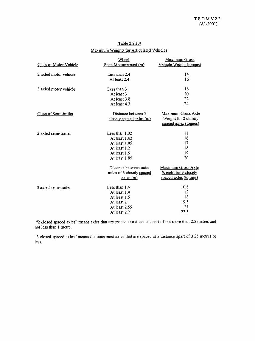
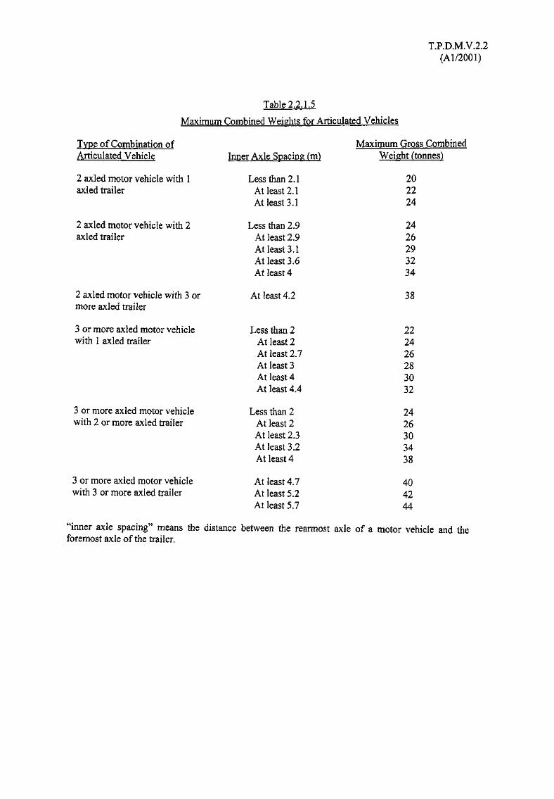
2.2.1.2 Table 2.2.1.2 shows the maximum weight of vehicles for the new legislation and Tables 2.2.1.4- 2.2.1.7 show how these are qualified.
2.2.1.3 The maximum permissible weights transmitted to the road surface, also contained in theRegulations, are as follows:
(i) For one wheel, where no other wheel is in the same line transversely, not greater than 4.5tonnes
(ii) For two wheels in the same line transversely, not greater than 9 tonnes
(iii) For two wheels in the same line transversely, if each wheel is fitted with 2 pneumatic tyresnot greater than 10 tonnes.
(iv) For more than 2 wheels in the same line transversely, not greater than 11 tonnes.
2.2.1.4 Maximum swept turning circles for vehicles given in the Road Traffic (Construction andMaintenance) Regulations are shown in Table 2.2.1.8.
2.2.1.5 Under the legislation the Commissioner also has powers to license vehicles in excess of thedimensions or weights shown in the tables.

T.P.D.M.V.2.2(Al/2001)
Table 2.2.1.1Overall Dimensions of Vehicles
Vehicle
Private CarTaxiInvalid CarriageLight BusBus
Single DeckDouble Deck
ArticulatedLight Goods VehicleMedium Goods VehicleHeavy Goods Vehicle
RigidArticulated
Special Purpose VehicleTricycleTrailerPedestrian-controlled Vehicle
OverallLength Cm)
6.36.36.36.9
1212151011
111612
13.54.3
OverallWidth Cm)
2.32.32.32.3
2.52.52.52.52.5
2.52.52.51.12.51.6
OverallHeight Cm)
2223
3.54.63.53.54.6
4.64.64.6
4.6
TABLE 2.2.1.2Maximum Weights of Vehicles
Class of Vehicle
Private CarTaxiInvalid CarriageLight BusBusLight Goods VehicleMedium Goods VehicleHeavy Goods VehicleMotor CycleMotor TricycleTrailer
MaximumGross Vehicle Weights (tonnes)
3334245.524380.50.638

T.P.D.M.V.2.2(Al/2001)
Table 2.2,13Maximum Weights for Rigid Vehicles
Maximum GrossClass of Rigid Vehicle Wheel Span Measurement (m) Vehicle Weights
(tonnes)
2 axled vehicle Less than 2.65 14At least 2.65 16
3 axled vehicle Less than 3 16At least 3 18At least 3.2 20At least 3.9 22At least 4.9 24
4 axled vehicle Less than 3.7 18At least 3.7 20At least 4.6 22At least 4.7 24At least 5.6 26At least 5.9 28At least 6.3 30
T.P.D.M.V.2.2(Al/2001)
Table 2.2.1.4
Maximum Weights for Articulated Vehicles
Class of Motor Vehicle
2 axled motor vehicle
3 axled motor vehicle
Class of Semi-trailer
2 axled semi-trailer
3 axled semi-trailer
WheelSpan Measurement (m)
Less than 2.4At least 2.4
Less than 3At least 3At least 3.8At least 4.3
Distance between 2closely spaced axles (m)
Less than 1.02At least 1.02At least 1.05At least 1.2At least 1.5At least 1.85
Distance between outeraxles of 3 closely spaced
axles (m)
Less than 1.4At least 1.4At least 1.5At least 2At least 2.55At least 2.7
Maximum GrossVehicle Weight (tonnes)
1416
18202224
Maximum Gross AxleWeight for 2 closelyspaced axles (tonnes)
111617181920
Maximum Gross AxleWeight for 3 closelyspaced axles (tonnes)
10.51218
19.521
22.5
"2 closed spaced axles" means axles that are spaced at a distance apart of not more than 2.5 metres andnot less than 1 metre.
"3 closed spaced axles" means the outermost axles that are spaced at a distance apart of 3.25 metres orless.
T.P.D.M.V.2.2(Al/2001)
Table 2.2.1.5
Maximum Combined Weights for Articulated Vehicles
Type of Combination of Maximum Gross CombinedArticulated Vehicle Inner Axle Spacing (m) Weight (tonnes)
2 axled motor vehicle with 1 Less than 2.1 20axled trailer At least 2.1 22
At least 3.1 24
2 axled motor vehicle with 2 Less than 2.9 24axled trailer At least 2.9 26
At least 3.1 29At least 3.6 32At least 4 34
2 axled motor vehicle with 3 or At least 4.2 38more axled trailer
3 or more axled motor vehicle Less than 2 22with 1 axled trailer At least 2 24
At least 2.7 26At least 3 28At least 4 30At least 4.4 32
3 or more axled motor vehicle Less than 2 24with 2 or more axled trailer At least 2 26
At least 2.3 30At least 3.2 34At least 4 38
3 or more axled motor vehicle At least 4.7 40with 3 or more axled trailer At least 5.2 42
At least 5.7 44
"inner axle spacing" means the distance between the rearmost axle of a motor vehicle and theforemost axle of the trailer.
T.P.D.M.V.2.2(Al/2001)
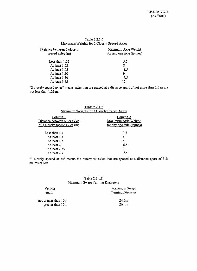
Table 2.2.1.6Maximum Weights for 2 Closely Spaced Axles
Distance between 2 closely Maximum Axle Weightspaced axles (m) for any one axle (tonnes)
Less than 1.02 5.5At least 1.02 8At least 1.05 8.5At least 1.20 9At least 1.50 9.5At least 1.85 10
"2 closely spaced axles" means axles that are spaced at a distance apart of not more than 2.5 m ancnot less than 1.02 m.
Table 2.2.1.7Maximum Weights for 3 Closely Spaced Axles
Column 1 Column 2Distance between outer axles Maximum Axle Weightof 3 closely spaced axles (m) for any one axle (tonnes)
Less than 1.4 3.5At least 1.4 4At least 1.5 6At least 2 6.5At least 2.55 7At least 2.7 7.5
"3 closely spaced axles" means the outermost axles that are spaced at a distance apart of 3.2imetres or less.
Table 2.2.1.8Maximum Swept Turning Diameters
Vehicle Maximum Sweptlength Turning Diameter
not greater than 10m 24.5mgreater than 10m 26 m
T.P.D.M.V.2.2(Al/2001)
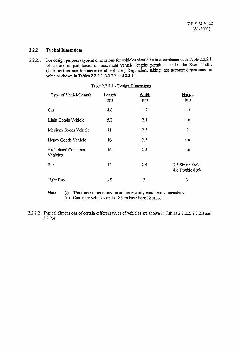
2,2.2 Typical Dimensions
2.2.2.1 For design purposes typical dimensions for vehicles should be in accordance with Table 2.2.2.1,which are in part based on maximum vehicle lengths permitted under the Road Traffic(Construction and Maintenance of Vehicles) Regulations taking into account dimensions forvehicles shown in Tables 2.2.2.2, 2.2.2.3 and 2.2.2.4
Table 2.2.2.1 - Design Dimensions
Type of VehicleLength
Car
Light Goods Vehicle
Medium Goods Vehicle
Heavy Goods Vehicle
Articulated ContainerVehicles
Bus
Light Bus
Length(m)
4.6
5.2
11
16
16
Width(m)
1.7
2.1
2.5
2.5
2.5
Height(m)
1.5
1.6
4
4.6
4.6
12
6.5
2.5 3.5 Single deck4.6 Double deck
Note : (i) The above dimensions are not necessarily maximum dimensions,(ii) Container vehicles up to 18.9 m have been licensed.
2.2.2.2 Typical dimensions of certain different types of vehicles are shown in Tables 2.2.2.2, 2.2.2.3 and2.2.2.4

VehicleMake
Mercedes Benz S55
Mercedes Benz C320
Mercedes Benz S600
Mercedes Benz C200
Jaguar Daimler V8
Jaguar Daimler XKR
Jaguar S-TYPE
AUDI S8
AUDI A6
Honda Civic
Honda Accord
Honda S2000
Volvo S80
Volvo V40
Volkswagen Bora
Mitsubishi Lancer
Mitsubishi Lancer MX5
Table 2.2.2.2
T.P.D.M.V.2.2(Al/2001)
Vehicle Dimensions - Private Cars
Length(m)
5.038
4.526
5.158
4.343
5.148
4.760
4.876
5.034
4.833
4.435
4.795
4.135
4.822
4.516
4.374
4.455
4.370
Width(m)
1.855
1.728
1.855
1.728
1.798
1.829
1.819
1.880
1.850
1.720
1.785
1.750
1.832
1.716
1.735
1.770
1.695
Height(m)
1.450
1.427
1 447
1 406
1.375
1.306
1.441
1.438
1.448
1.440
1.455
1.285
1.452
1.460
1.445
1.450
1.430
LI(m)
0.867
0.755
0867
0.788
0.914
0.972
0.854
1.011
1.006
0.805
0.975
0.805
0.964
0.912
0.874
0.895
0.850
L2(m)
2.965
2.715
3.085
2.715
2.995
2.588
2.909
2.887
2.758
2.620
2.715
2.405
2.791
2.562
2.513
2.625
2.600
L3(m)
1.206
1.056
1.206
0.840
1.239
1.20
1.097
1.136
1.069
1.010
1.105
0.930
1.067
1.043
0.987
0.935
0.920
UnladenWl W2 Weight
(tonnes) (tonnes) (tonnes)
1.830
1.490
1.880
1.540
1.845
1.735
1.733
1.750
1.750
1.110
1.490
1.240
1.506
1.367
1.261
1.400
1.140
MaxG.V.W.(tonnes)
2.400
2.045
2.460
2.050
2.260
2.010
2.190
2.350
2.290
1.580
1.905
1.350
1.531
1.780
1.800
1.695
1.600
Turning DiameterSwept,
(m)
11.7
10.7
11.7
10.7
12.4
11.0
12.1
12.3
11.7
10.8
11.0
10.8
11.2
10.6
10.9
9.8
9.8
LI = Distance between front and front axleL2 = Distance between axlesL3 = Distance between rear axle and rear

T.P.D.M.V.2.2(Al/2001)
Table 2.2.2.3Vrhirlc Dimensions -JJpJit Goods Vehicles
VehicleMake
Mercedes-Benz 416CDI
Mercedes-Benz 312D
Nissan Caravan
Nissan E24
Mitsubishi L300
Volswagon LT46
Volswagon LT35
Length(m)
6.590
6.535
4.690
4.790
4.805
6.535
5.585
Width(m)
1.988
1.933
1.690
1.690
1.690
1.994
1.993
Height(m)
2.610
2.570
1.950
1.990
1.960
2.610
2.570
LI(m)
0.939
0.882
0.980
1.100
1.280
0.855
0.885
L2(m)
4.025
4.025
2.645
2.645
2.435
4.025
3.550
L3(m)
1.625
1.480
1.040
1.045
1.090
1.625
1.150
Wl(tonnes)
1.750
1.600
1.350
1.350
1.200
1.750
1.600
W2(tonnes)
3.200
2.240
1.680
1.680
1.450
3.200
2.240
UnladenWeight(tonnes)
2.360
2.050
1.550
1.605
1.370
2.302
1.895
Max Turning DiameterG.V.W.(tonnes)
4.600
3.500
2.965
2.750
2.505
4.600
3.500
Swept,(m)
14.3
14.3
10.8
10.8
9.8
14.3
12.8
Where LI = Distance between front and front axleL2 = Distance between axlesL3 = Distance between rear axle and rear
W1 = Maximum axle load, front axleW2 = Maximum axle load, rear axle
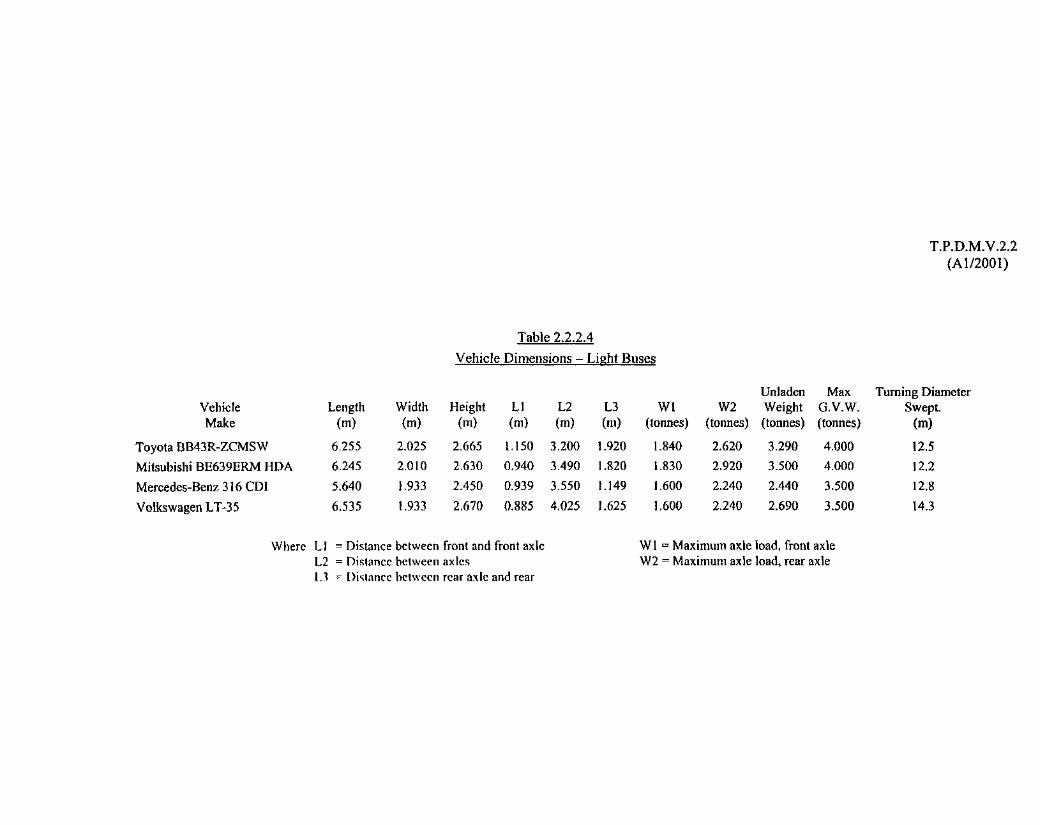
VehicleMake
Toyota BB43R-ZCMSW
Mitsubishi BE639ERM HDA
Mercedes-Benz 316 GDI
Volkswagen LT-35
Table 2.2.2.4
T P.D.M.V.2.2(Al/2001)
Vehicle Dimensions - Light Buses
Length(m)
6.255
6.245
5.640
6.535
Width(m)
2.025
2.010
1.933
1.933
Height(m)
2.665
2.630
2.450
2.670
LI(m)
1.150
0.940
0.939
0.885
L2(m)
3.200
3.490
3.550
4.025
L3(m)
1.920
1.820
1.149
1.625
Wl(tonnes)
1.840
1.830
1.600
1.600
W2(tonnes)
2.620
2.920
2.240
2.240
UnladenWeight(tonnes)
3.290
3.500
2.440
2.690
Max Turning DiameterG.V.W. Swept,(tonnes) (m)
4.000
4.000
3.500
3.500
12.
12.
12,
,5.2
.8
14.3
Where LI = Distance between front and front axleL2 = Distance between axlesL3 ~ Distance between rear axle and rear
Wl = Maximum axle load, front axleW2 = Maximum axle load, rear axle

Table 2.2.2.5
T? DM.V.1.1(Al/2001)
Vehicle Dimensions - Medium and Heavy Goods Vehicles
VehicleMake
Mercedes-Benz 2628K
Mercedes-Benz 3234K
Mercedes-Benz 1823LNR
Volvo FL6E42R
VolvoFM126X4
VolvoFL108X4
Man 25.284 MNLRC
Man 35.364 VFRC
Man 15.224LRC
HinoFYlKUMA
HinoFSlKTMA
HinoGHURKA
Nissan CWB 457LMNR
Nissan COB 457SMNR
Nissan PK212NHNN
Length(m)
7.405
8.760
9.190
10.00
7.460
9.289
10.12
9.869
9.700
10.74
10.33
9.770
7.800
8.960
9.530
Width(m)
2.490
2.500
2.490
2.490
2.467
2.490
2.500
2.500
2.490
2.490
2.490
2.360
2.490
2.490
2.425
Height(m)
2.700
3.075
2.650
2.725
2.931
2.828
2.915
3.075
2.600
2.870
2.845
2.605
2.855
2.910
2.725
LI(m)
1.440
1.360
1 440
1.501
1.365
1.419
1.620
1.525
1.225
1.410
1.410
1.235
1.400
1.400
1.280
L2(m)
3.600
1.696
5.400
5.800
3.900
1.750
5 150
1.500
5.475
1.750
5.000
5.800
4.350
1.850
5.650
L3(m)
1.350
3.504
2.350
2.700
1.370
3.850
1.350
4.325
3.000
3.500
1.350
2.600
1.300
3.150
2.600
L4(m)
0.750
1.350
0.825
1.370
2.00
1.400
1.350
2.535
1 280
1.300
L5 Wl(m) (tonnes)
7.100
0.630 6.700
6.500
7.100
7.100
0.900 7.100
7.500
0.950 7.100
6.000
2.700 6.700
6.700
6.000
6.000
1.140 6.000
6.000
W2(tonnes)
9.000
6.700
10.00
10.00
9.000
7.100
7.500
7.100
10000
6.700
9.000
10.000
9.000
6.000
10.00
W3(tonnes)
9.000
9.000
9.000
9.000
7.500
9.000
9.000
9.000
9.000
9.000
MaxW4 G.V.W.
(tonnes) (tonnes)
24.000
9.000 30.000
16.000
16.000
24.000
9.000 30.000
24.000
9.000 30.00
16.000
9.000 30.00
24.00
16.00
24.00
9.000 30.00
16.00
Turning DiameterSwept,
(m)
17.5
23.0
20.5
18.91
15.41
22.01
20.01
26.01
19.01
22.5
21.2
21.6
15.2
18.2
18.8
Where Li = Distance between front and first axleL2 = Distance between first and second axleL3 = Distance between second and third axleL4 = Distance between third and fourth axle or rearL5 — Distance between fourth axle and rear
Wl = First axle loadW2 = Second axle loadW3 = Third axle loadW4 = Fourth axle load

T.P.D.M.V.2.2(Al/2001)
Table 2.2.2.6
VehicleMake
Man 33.464 DFLRT
Man 19.414 FLRT
Hino SH1KDMA
HinoSSlKKMA
Length(m)
7.075
6.150
5700
6.860
Width(m)
2.490
2.490
2.490
2.490
Height(m)
3.250
2.850
2.825
3.235
Vehicle
LI(m)
1.525
1.525
1.420
1.420
Dimensions - Medium and Tractor Vehicles
L2(m)
3.175
3600
3.200
3.300
L3(m)
1.400
1.025
1.080
1.350
L4(m)
0.725
0.790
L5 Wl(m) (tonnes)
8.000
7.100
6.700
6.700
W2(tonnes)
9.000
10.000
10.000
9.000
W3 W4(tonnes) (tonnes)
9.000
2.000
Max Turning DiameterG.V.W. Swept,(tonnes) (m)
24.000
16.000
16.000
24.000
17.00
15.00
12.8
15.8
Where LI = Distance between front and first axleL2 = Distance between first and second axleL3 = Distance between second and third axleL4 = Distance between third and fourth axle or rearL5 = Distance between fourth axle and rear
Wl = First axle loadW2 = Second axle loadW3 = Third axle loadW4 = Fourth axle load

T.P.D.MV.2.2(Al/2001)
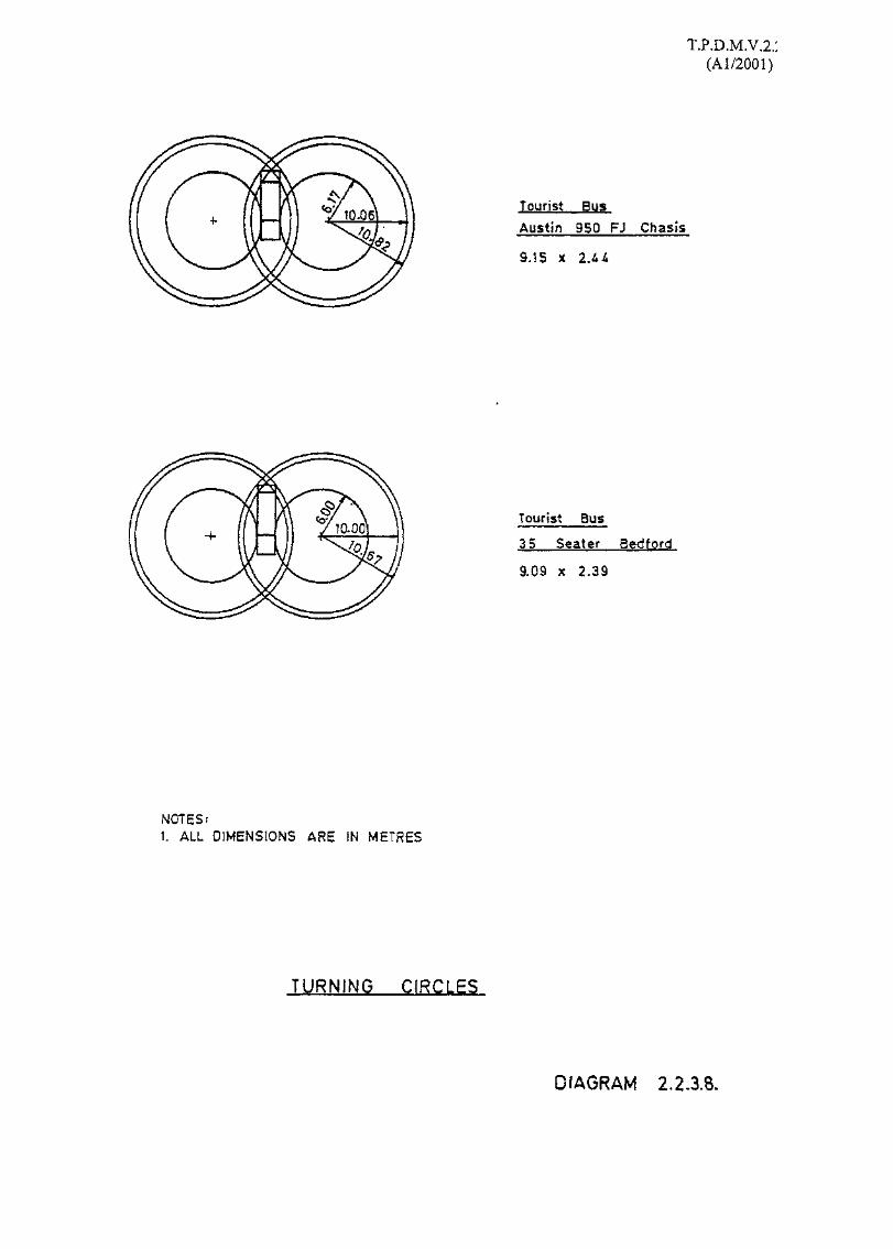
2.2.3 Turning Circles
2.2.3.1 Diagrams 2.2.3.1 - 2.2.3.8 and 2.2.3.11 show dimensions of turning circles for various types ofvehicles.
2.2.3.2 In TRRL Report LR 608 "Road Width Requirements of Commercial Vehicles", calculations asto road widths required for different types of vehicles have been determined.
2.2.3.3 A further means for determining the swept area of a turning vehicle is the "Schneider" methodand is summarised in Diagrams 2.2.3.9 and 2.2.3.10. This method determines the turning areaof a vehicle by plotting the progressive position of the vehicle and whilst not precise is probablysufficiently accurate for assessing road width requirements. It can be used for any radius ofturn.

MINIMUM KERB TO KERB CLEARANCE
MINIMUM WALL TO WALL CLEARANCE
760 2740 1070H-4- 4—I
/
oir>k-
/4570 'DIMENSIONS OF DESIGN VEHICLE
NOTE;
ALL DIMENSIONS IN MILLIMETRES
RECOMMENDED MINIMUM STANDARDS OFTURNING CIRCLE FOR PRIVATE CARS
DIAGRAM 2.2.3.1.
Hj-db
toto

TURNING CIRCLE
Pr i va te Car(Large Size)
5.i,9 x 1.88
DIAGRAM 2.2.3.2>
I ALL DIMENSIONS ARE IN METRES

MINIMUM KERB TO KERBCLEARANCE
MINIMUM WALL TO WALLCLEARANCE
TURNTABLE
920 4270 2UQ
763Qi
DIMENSIONS OF DESIGNVEHICLE
MINIMUM CLEARANCEFOR TURNING
MIN. STANDARD TURNING CIRCLE FOR GOODS VEHICLESWIN. STANDARD TURNTABLE FOR GOODS VEHICLES
RECOMMENDED MINIMUM STANDARDS OF TURNING CIRCLE &TURNTABLE FOR GOODS VEHICLES
NOTE; ALL DIMENSIONS IN MILLIMETRESDIAGRAM 2.2.3.3.

/MINIMUM WALL TO WALL CLEARANCE
MINIMUM KERS TO KERB CLEARANCE
DATA
DESIGN VEHICLE EXTRA HEAVY PUMPWHEEL BASE (B) =5180TURNING RADIUS (r) = 10500
MINIMUM CLEARANCEFOR TURNING
DIMENSIONS OF DESIGNVEHICLE
REAR PART OFVEHICLE
.DIA. = 14 200 MIN.
DIA. = 6 800 MIN.
TURNTABLE
(A) MINIMUM HEADROOM REQUIRED 4.37m(B) PROJECTION OF OUTRIGGERS FROM BODY LINE 0.61m(C) HEADROOM REQUIRED OR TO ELEVATE A TURNTABLE LADDER 10.06m(D) ALL DIMENSIONS IN MILLIMETRES
CHARACTERISTICS OF LARGER FIRE APPLIANCES DIAGRAM 2.2.3.4 §<r^ k>:

MINIMUM WALL TO WALL CLEARANCE
MINIMUM KERB TO KERB CLEARANCE
PATH OF TRAILER RIGHTREAR , WHEEL
«* 1 60001 2 2 0 0
*iI1I
0-<?<tCM
NOTE;
ALL DIMENSIONS IN MiLLiMETRES
->
CONTAINER TURNING CIRCLES DIAGRAM 2 , 2 . 3 . 5

T.P.D.M.V.2.2(Al/2001)
Q
3:
1 80 TURNING
90° TURNING
Container
NOTES:1. ALL DIMENSIONS ARE IN METRES
DIAGRAM 2.2.3.6

T.P.D.M.V.2.2
BUS DAIMLER FL££TUNE METRO BUS
12m BUS
NOTES:1. ALL DIMENSIONS ARE SN METRES
BUS TURNJNG CIRCLES DIAGRAM 2.2.3.7.
T.P.D.M.V.2.:(Al/2001)
Tourist Bus
Austin 950 FJ Chasls
9.15 x 2.JU
Tourist Bus
35 Seater Bedford
9.09 x 2.39
NOTES:1. ALL DIMENSIONS ARE IN METRES
TURNING CIRCLES
DIAGRAM 2.2.3.8.

T P n Twf V 7 ?
T.P.D.M.V.2.2(Al/2001)
DIAGRAM 2 . 2 . 3 . 9
PREDICTION OF RIGID VEHICLE SWEPT PATH-SCHNEIDER METHOD
I t"
12"
13 U
C1
t . DRAW APPROPRIATE RADIUS Rt, i.e. 1 0 m , 1 2 m , 1 5 m .
2. DRAW OUT LIKE OF VEHICLE WHERE Ai 81 & Di Ct* WIDTH , Ai Di AND Bt Ci - li + 12 * 13 * U ANDYi OUTSIDE POINT OF FRONT AXLE , COINC IDES WITHTANGENT POINT , AND Ai Yt * li , Yi X 1 = t 2 * la ANDXiDi= U .
3. DRAW ARC FROM POINT YI OF RADIUS > THAN WHEELBASE, i.e. Yi Xi TO INTERSECT RADIUS Ri AT Yz .
4 POINT E IS M I D - P O I N T OF ARC Y2 Yi .
5. J O I N E Xt
6. DRAW ARC OF RADIUS Yi Xl FROM POINT Y 2 .
7. W H E R E ARC INTERSECTS E Xt IS POINT X z , N E X TP O S I T I O N OF OUTSIDE R E A R AXLE .
8. JOIN X2 Y2
9. CONSTRUCT A2, B 2 . C 2 , D 2 NEXT POSIT ION OF V E H I C L E ,i. e. A2 Y2 = li ,
A2 B2 = W I D T H .
A 2 D 2 = U * I 2 * 13 * I 4
10. REPEAT UNTIL VEHICLE COMPLETES T U R N , eg. 90° OR 180°.

T.P.D.M.V.2.2(Al/2001)
DIAGRAM 2 .2 .3 .10
PREDICTION OF ARTICULATED VEHICLE SWEPT PATH-SCHNEIDER METHOD
L2
.0 , 0:1.1 1 U
00Iy I . l a
12 U
1. DRAW APPROPRIATE RADIUS, 10m, 15m etc.
2. DRAW OUTLINE OF TRACTOR AND TRAILER UNITS.THE TRACTOR UNIT SHOULD BE PLOTTED AS FOR THERIGID VEHICLE EXAMPLE. HOWEVER, WHENPLOTTING THE NEXT POSITION OF THE TRACTORTHE ARC RADIUS Yi Y2 MAY BE TAKEN ASBEING GREATER THAN THE WHEEL BASE.APPROXIMATELY 1-5 x WHEEL BASE HAS BEENFOUND TO BE CONVENIENT LENGTH.
3. DRAW RADIUS R* THROUGH PIVOT POINT ZiCONCENTRIC TO OUTSIDE RADIUS,
4. PLOT NEXT POSITION OF TRACTOR UNIT AND22 NEXT POSITION OF PIVOT POINT , ALONG R2 .WHERE U a DISTANCE OF PIVOT FROM REAROF TRACTOR.
5. FIND P MID POINT OF ARC Zi Z: .
6. DRAW LINE FROM Wt TO P . WHERE Wi Qi = t *
7. DRAW ARC OF RADIUS 16 * I? FROM 22
5. WHERE ARC INTERSECTS Wi P IS NEXT POSITIONW2 OF CENTRE OF REAR AXLE .
9. JOIN W2 22 [ i OF TRAILER ) AND CONSTRUCTLz M2 N2 02 .W H E R E L 2 M 2 * W I D T H OF TRAILERAND M2 N* » 15 * U * 17 + U .
10. REPEAT UNTIL COMPLETE TURN PLOTTED.

T.P.D.M.V.2.2T.P.D.M.V.2.2
(Al/2001)
Pub I i c L i qht Bus6255 x 2025
TURNING CIRCLE
NOTE:1. ALL DIMENSIONS IN MILLIMETRES
DIAGRAM 2.2.3.

T.P.D.M.V.2.2(Al/2001)
2.3 Passenger Car Units
2.3.1 P.C.U. Values
2.3.1.1 Passenger Car Unit values are given in Table 2.3.1.1. Although p.c.u.'s are no longer used inthe determination of the capacities of roundabouts or links these values have been included forreference purposes.
Table 2.3.1.1 - Passenger Car Units
Private Car, Taxi
Light Goods Vehicle
Motor Cycle MotorScooter
Medium GoodsVehicle
Heavy Goods Vehicle
Bus
Pedal Cycle
Tram
Light Bus
Special purpose bus
Light Van
Tractor unit
Eauivalent Value in P.C.U.'s
UrbanStandard
1.0
1.5
0.75
RuralStandard
1.0
1.5
1.0
Roundabout
1.0
1.5
0.75
TrafficSignalDesign
1.0
1.5
0.40
Terrain
Ave Hilly Ave Hilly2.0 3.0 2.0 4.0
2.8 1.75
2.5 3.0
3.0 4.0
0.35
3.0
1.5
2.0
1.25
3.0
2.5 3.0
3.0 4.0
0.5
-
1.5
2.0
1.25
3.0
2.8
2.8
0.5
-
1.5
1.25
1.75
2.0
0.2
3.5-5.0+
1.5
1.25
2.3.1.2 For Medium or Heavy Goods Vehicle pcu values for hilly conditions are appropriate where thegradient is greater than 4%, or there are long lengths of 4% gradient.
2.3.1.3 For trams pcu values vary from 3.5 pcu's for a clear approach to a junction, to 5.0 pcu's where atram island is sited near an approach. Where a tramway reserve is provided or where thefrequency of tram movements is so high as preclude the use of its lane by other vehicles, thatlane should be excluded in capacity calculation for mixed traffic.
2.3.1.4 Where, in any context, it is considered that p.c.u.'s are appropriate for design or other purposes,the values used must be in accordance with Table 2.3.1.1.

T.P.D.M.V.2.2(Al/2001)
2.4 Design Flow Characteristics
2.4.1 Design Flow
2.4.1.1 Design flow is the maximum volume of vehicles using the road without the traffic densitybecoming such as to cause unreasonable delay, hazard or restriction to the drivers freedom tomanoeuvre. Typical values are shown in Table 2.4.1.1
Table 2.4.1.1Design Flows for Two Way Urban Roads
Road Type
Expressway/trunk road
Primary distributor nofrontage crossings, nostanding vehicles,negligible cross traffic
District distributorfrontage development,side roads, pedestriancrossings, bus stops,loading restrictions atpeak hours.
2 lane carriageway
Peak hourly flowVeil/hour, both
directions of flow *
6.75m
1400
7.3m
2000
1700
10.0m
3000
2500
Undivided carriageway
Peak hourly flowVeh/hour, one
direction of flow
4 lane
123m 13.5m
2550 2800
i
1700 1900
14.6m
3050
2100
Dual carriageway
Peak hourly flowVeh/hour, one
direction of flow i
Dual 2 lane
Dual6.75m
*2950
Dual7.3m
3600
*3200
Dual 3lane j
Dual !l l . O m i
5700
*4SOO
j
1
"" 60/40 directional split can be assumed.
* Includes division by line of refuges as well as central reservations; effective carriageway widthexcluding refuge width is used
2.4.1.2 The design flows in Table 2.4.1.1 allow for a proportion of heavy vehicles equal to 15%. Noallowance will need to be made for lower proportions of heavy vehicles; the peak hourly flow atthe year under consideration should be reduced following Table 2.4.1.2 when the expectedproportion exceeds 15%:

T.P.D.M.V.2.2(Al/2001)
Table 2.4.1.2
Reduction of Peak Hourly Flow forHeavy Vehicles in Excess of 15%
Heavy vehiclecontent
15-20%20 - 25%
Total reduction in flow level (veh/h)
Expressway, trunkroad and dualcarriageway
per lane
100150
10m wide and aboveSingle carriageway
road
per carriageway
150225
Below 10m wideSingle carriageway
road
per carriageway
100150
2.4.1.3 For local roads, the design flow of a 2-lane single carriageway may be taken as 800 veh/h, 2-way, due to the presence of loading activities, standing vehicles and pedestrian crossings.
2.4.1.4 The Design Year will be determined by the particular project under consideration. A designyear between 15 and 20 years after the expected commissioning of the road should be adopted,the exact number of years being dependant on the availability of planning data. Currently theyear 2016 is generally adopted since major strategic and regional transport planning studies arecarried out with a planning horizon up to 2016. However, the Design Year chosen would besubject to the agreement of Transport Department.
2.4.1.5 Where predicted flows indicate a carriageway width in excess of 3 lanes is required for a dualcarriageway road other considerations such as, the practicality of providing this, trafficoperating conditions, and whether an alternative and/or an additional route should be provided,will also need to be taken into account.

T.P.D.M.V.2.2(A 1/2001)
2.4.2 Estimation of Design Flows
2.4.2.1 In assessing the road width requirements, it is necessary to estimate the likely flow in the PeakHour of the Design Year. However such estimation of peak hour flows so many years into thefuture cannot, of course, be made with any degree of precision or confidence. Therefore toprovide a uniform approach, design year peak hour flows shall be determined on the basis of thenormal peak hour/AADT flow relationships in the Territory. Table 2.4.2.1 shows the relevantpeak hour factors.
Table 2.4.2.1Peak Hour Factors
Peak hourRoad Type 2~wav - A.A.D.T %
1. Urban Trunk Roads and Primary 6.5Distributors
2. Rural Trunk Roads, Rural Roads A, and 8Rural Roads B
3. District Distributors and Local Roads 10
2.4.2.2 The estimated Peak Hour Design Flow (P) for single 2-lane carriageways is found directly byapplying the peak hour factor to the A.A.D.T. and for single 4-lane carriageways and dualcarriageways by applying the peak hour factor, and a peak hour directional split of 45/55%.
2.4.2.3 Although it is the peak hour flows that must be used to determine appropriate road widths itmay be helpful for analysis to consider the equivalent A.A.D.T. flows that will result from thehourly design flows. These are tabulated in Table 2.4.2.2.

T.P.D.M.V.2.2(Al/2001)
Table 2.4.2.2
Annual Average Daily Traffic Flow
Equivalents to Table 2.4.1.1 - 2 way traffic
Single 10.3 mCarriageway 2-1 ane Wide 2-lane
1. Urban trunk roads and primary 12300 18500distributors
2. Rural trunk roads, rural roads 10000 15000A and rural roads B
3. District distributors and local 8000 12000roads
Dual Carriageways Dual 2-lane Dual 3-lane
1. Trunk roads and primary 78500 118000distributors
2. Rural trunk roads, rural roads 63500 96000A and rural roads B
3. District distributors and local 51000 76000roads
4-lane
67000
54500
43600

T.P.D.M.V.2.2
2.4.3 Peak Hourly Flows/Design Flow Ratios P/Df
2.4.3.1 Comparison of predicted flows to design flows may be useful in analyzing a network. Suchcomparisons should however always be related to hourly flows as daily flows can be extremelymisleading due to the variability of peaking characteristics.
2.4.3.2 Table 2.4.3.1 indicates the implications of various Peak Hourly Flows/Design Flow ratios, P/Df.
2.4.3.3 With regard to existing roads care should be exercised in interpreting P/Df ratios as manylengths of existing road are constrained by the capacity of existing junctions, and lack ofstopping restrictions. Whilst from Table 2.4.3.1 a P/Df ratio of 0.7 might infer adequateoperating conditions, junctions both within and at the end of the road link may be such that theflow could never be achieved in practice, and the link would be severely congested well beforea P/Df ratio of 0.7 is reached.

T.P.D.M.V.2.2(Al/2001)
Table 2A3.1Implication?pf P/Df Ratios
P/Df Ratio
Up to 0.5
0.5-0.75
0.75-1.0
1.0-1.2
1.2-2.0
Dual Carriageway
Easy flow conditions. Parkingrestrictions should be applied unlessadditional bay widths are provided. Ontrunk roads and primary distributors 24-hrs stopping restrictions should apply.
Generally easy conditions. All dayparking restrictions and peak hourstopping restrictions may be required onroads other than trunk and primarydistributors where 24-hr stoppingrestrictions should apply.
Well used conditions. All day stoppingrestrictions on roads other than trunkand primary distributors where 24-hrstopping restrictions should apply.
Maximum utilisation of route. At leastall day if not 24-hr stopping restrictionson all types. Occasional unstable flowconditions. Adequacy of weaving andmerging areas essential.
Not applicable.
Single Carriageway
Generally easy conditions. On streetparking may be applicable on districtand local distributor roads.
Generally well used. 24-hr parkingrestrictions will generally be required,though parking on local distributorscan be tolerated.
Very well used conditions. At leastpeak hour stopping restriction required,and parking restrictions at other times.On long rural road links freedom toovertake will be restricted.
Heavily loaded conditions. All daystopping restrictions required andparking restrictions at other times. Onlong rural roads overtaking will beactually impossible resulting in longplatoons unless additional overtakingopportunities provided. For easyconditions next higher category of roadshould be adopted.
Maximum utilisation of route.Unstable flow conditions. Adequacy ofjunctions and all day stoppingrestrictions essential.For rural roads and normal urbanconditions next higher category of roadshould be adopted.

Revised in December 2001
TRANSPORT PLANNING & DESIGN MANUAL
Volume 2
Chapters - Road Characteristics
Prepared by:Road Safety and Standards Division Transport-Department

T.P.D.M.V.2.3(Al/2001)
Contents
Sections
3.1 References
3.2 Road Types3.2.1 Rural Road Types3.2.2 Urban Road Types3.2.3 Expressways
3.3 Road Alignment3.3.1 General Principles33.2 Design Speed3.3.3 Horizontal Curvature3.3.4 Transitional Design3.3.5 Sight Distance3.3.6 Gradients3.3.7 Vertical Curves3.3.8 Climbing Lanes For Single Carriageway Roads3.3.9 Climbing Lanes For Dual Carriageway Roads
3.4 The Road in Cross Section3.4.1 Cross fall3.4.2 Carriageway Widths in Urban Areas3.4.3 Carriageway Widths in Rural Areas3.4.4 Widening on Curves3.4.5 Service Roads3.4.6 Cargo Handling Areas3.4.7 Central Reserves and Traffic Island3.4.8 Emergency Crossings3.4.9 Verges, Marginal Strips and Hard Shoulders3.4.10 Police Observation Platforms3.4.11 Footways3.4.12 Typical Cross Sections
3.5 Highway Clearances3.5.1 Vertical Clearances for Structures over Pavements3.5.2 Horizontal Clearance from Carriageway
3.6 Run-ins and Footway Crossings3.6.1 Restrictions3.6.2 Location of Run-ins3.6.3 Layout of Run-ins3.6.4 Vehicular access to Short Term Tenancy (S.T.T.) Sites and Short Term Waiver
(S.T.W.) Sites

T.P.D.M.V.2.3(Al/2001)
3.7 Pedestrian Crossing Facilities3.7.1 Planning of Pedestrian Crossing Facilities3.7.2 At-Grade Crossings
3.7.3 Zebra Crossings
3.7.4 Signal Light Controlled Crossings
3.7.5 Cautionary Crossings at Signal Controlled Junctions
3.7.6 Uncontrolled Cautionary Crossings
3.7.7 Grade Separated Crossings
3.7.8 Escalators at Footbridges and Elevated Walkways
3.8 Cycle Tracks3.8.1 General3.8.2 Provision of Cycle Tracks
3.8.3 Design of Cycle Tracks
3.8.4 Signs and Markings for Cycle Tracks
3.9 Railings, Barrier Fences and Crash Cushions3.9.1 General
3.9.2 Railings
3.9.3 Barrier Fences3.9.4 Crash Cushions
3.10 Road Tunnels3.10.1 Geometric Design Standards
3.10.2 Road Cross Section in Tunnels
3.10.3 Signing and Signalling of Tunnels
3.10.4 Lighting for Tunnels
3.11 Single Track Access Roads3.11.1 Introduction3.11.2 Use
3.11.3 Design Flows
3.11.4 Horizontal Alignment
3.11.5 Sightlines
3.11.6 Vertical Alignment
3.11.7 Minimum Carriageway Width
3.11.8 Footpaths and Verges
3.11.9 Passing Places and Lay-Bys
3.11.10 Parking
3.11.11 Turning Facilities
3.11.12 Traffic Aids
3.11.13 Use by Public Transport

T.PD.M.V.2.3(Al/2001)
Tables
3.3.2.1 Design Speeds3.3.3.1 Appropriate Radii and Super Elevation3.3.4.1 Transition Lengths3.3.5.1 Sight Distances3.3.6.1 Maximum Gradients3.3.7.1 Minimum K.Values for Vertical Crest Curves3.3.7.2 Minimum K Values for Vertical Sag Curves
3.4.2.1 Minimum Carriageway Widths in Urban Areas3.4.3.1 Minimum Carriageway Widths in Rural Areas3.4.4.1 Appropriate Carriageway Widths on Curves (m)3.4.5.1 Carriageway Widths of Service Roads (m)3.4.7.1 Minimum Widths of Central Reserves for Road Traffic Signal Installations3.4.11.1 Minimum Width of Footways3.4.11.2 Level of Flow when Additional Footway Width is required at Bus Stops and Taxi/PLB
Stands
3.5.1.1 Vertical Clearances for Structures over Pavements3.5.2.1 Horizontal Clearances from the Carriageway to obstructions
3.6.3.1 Length of Visibility Line "x"
3.7.2.1 Crossing Widths According to Approximate Pedestrian Flows3.7.3.1 Criteria for Zebra Crossings in Rural Areas3.7.3.2 Sight Distance for Zebra Crossings3.7.7.1 Capacities for Footbridges and Subways3.7.7.2 Design Standards for Footbridges and Subways3.7.7.3 Minimum Dimensions for Segregated and Unsegregated Subways for Pedestrians and
Cyclists3.7.7.4 Stopping Sight Distance for Cyclists
3.8.2.1 Guidelines for the Provision of Cycle Facilities3.8.3.1 Cycle Track Widths
3.9.3.1 Dynamic Deflection for Various Barrier Types and Speeds3.9.3.2 Suggested Flare Rates (1 :x) for Safety Fence
3.10.2.1 Summary of carriageway and walkway dimensions in Tunnels
3.11.7.1 Widths on Straights and Bends

T.P.D.M.V.2.3(Al/2001)
Diagrams
3.3.8.1 Calculation of Gradient for Climbing Lane Purposes
3.3.8.2 Start of Climbing Lane
3.3.8.3 End of Climbing Lane
3.3.8.4 Crest Curve Between Two Climbing Lanes
3.3.9.1 Dual Carriageway Climbing Lane Justification
3.3.9.2 Climbing Lane Provision within Standard Highway Width
3.3.9.3 Start of Dual Carriageway Climbing Lane
3.3.9.4 End of Dual Carriageway Climbing Lane
3.4.5.1 Minimum Turning Tee for Heavy Goods Vehicles and Turning Circle for Cul-De-Sac
3.4.5.2 Minimum Turning Areas
3.4.7.1 Traffic Islands at Tee Junctions
3.4.7.2 Traffic Islands at 4-way Junctions
3.4.10.1 Police Observation Platform, Typical Layout, Elevation and Section
3.4.12.1 Trunk Roads, Typical Cross Sections
3.4.12.2 Primary Distributor Roads, Typical Cross Sections
3.4.12.3 Dual Carriageway Roads, Typical Cross Sections
3.4.12.4 4-Lane Roads, Typical Cross Sections
3.4.12.5 Urban Single Carriageway Roads, Typical Cross Sections
3.4.12.6 Rural Single Carriageway Roads, Typical Cross Sections
3.4.12.7 Service Roads, Typical Cross Sections
3.4.12.8 Industrial Access Roads, Typical Cross Sections
3.6.3.1 Details of Footway Vehicle Crossing
3.6.3.2 Footway Crossing for Vehicle Entrance (For Skew Run-in)
3.6.3.3 Footway Crossing for Filling Stations
3.6.3.4 Visibility Area at Run-ins
3.7.2.1 Ramping of Kerb and Footway at Designated Pedestrian Crossing
3.7.3.1 Indication of Zebra Pedestrian Crossing
3.7.3.2 Indication of Zebra Controlled area
3.7.4.1 Typical Signalised Crossing Layout
3.7.7.1 Cross-Section of a Typical Segregated Subway for Combined Use
3.7.7.2 Stopping Sight Distance for Cyclists
3.9.2.1 Tubular Railings
3.9.2.2 Type 2 Railings
3.9.3.1 Typical Barrier Fences
3.10.2.1 Typical Road Tunnel Cross Section

T.PD.M.V.2.3(Al/2001)
3.1 References
1. Departmental Standard TD 9/93 Road Layout and Geometry: High-way Link DesignD.O.Tp. 1993.
2. Country Surveyors' Society Highway Transition Curve Tables (metric). The CarriersPub. Co. Ltd. 1965.
3. T.T.S.D. Data Record 182. Pedestrian Movement in the Central District of HongKong 1974.
4. D.O.E. Technical Memorandum H2/70 - Pedestrian Subways, Layout andDimensions.
5. United Nations - Recommended Practice for the Design and Layout of Cycle Tracks,Feb. 1973.
6. Highways Office - Guide Lines for the design of Cycle Facilities - New Territories.,Highways Office of Public Works Department, 1976.
7. Traffic Engineering Division - A Policy on Run-ins, July 1970.
8. Report of the Working Party on Transport for the Disabled, March 1975.
9. Design Manual: Barrier Free Access, 1997. Buildings Department, 1997.
10. Highway Capacity Manual 1965, Highway Research Board, Special Report 87.
11. Departmental Standard TD 31/93. Subway for Pedestrians and Pedal Cyclists Layoutand Dimensions, D.O.Tp. 16.B.S. 5395: 1977. Code of Practice for Stairs.
12. Road Traffic (Traffic Control) Regulation 1984.
13. Hong Kong Long Term Road Study - Freeman Fox Wilbur Smith Associates, 1968.
14. Third Comprehensive Transport Study - Wilbur Smith Associates Limited, October1999.
15. Comprehensive Traffic Surveillance and Control Study. - Maunsell Consultants Asia- 1980.
16. P.I.A.R.C. Road Tunnel Technical Committee Report of Working Group IV. Geometry^1975.
17. Departmental Advice Note TD 42/95. Junctions and Accesses: Geometric design ofMajor/Minor Priority Junctions. U.K. Department of Transport
18. The Research and Development Background to "Highway Link Design" D. Simpsonand J.A. Kerman. Traffic Engineering and Control, Sept. 1982.
19. Departmental Advice Note TA 66/95. Police Observation Platforms on Motorways.The Highways Agency.
20. The Overall Effect on Accidents at Sites Where Zebra Crossings were Installed. J.R.Landles. Traffic Engineering Control January 1983.
21. Data Record No. 3 61. Warrants for Escalators at Footbridges.

T.PD.M.V.2.3(Al/2001)
22. Providing For The Cyclist. Institution of Highways and Transportation July 1983.
23. Structures Design Manual for Highways and Railways, 1997.
24. Roads and Traffic in Urban Areas. The Institution of Highways and Transportationwith the Department of Transport. 1987.
25. Pedestrianisation Guidelines. The Institution of Highways and Transportation. 1989.
26. Design Manual for Roads and Bridges, Volume 6 Road Geometry. The Departmentof Transport, June 1993.
27. Public Lighting Design Manual, Highways Department
2 8. Highways Department Standard Drawings, Highways Department
29. The Standard Drawings of Structures Division of Highways Department
30. Departmental Standard TD 36/93, Subways for Pedestrians and Pedal Cyclists Layoutand Dimensions, D.O.Tp.
31. Roads and Traffic in Urban Areas, Institution of Highways and Transportation withthe Department of Transport, 1987
32. National Cooperative Highway Research Program (NCHRP) Report 350, TransportResearch Board, National Research Council, U.S.A.
33. Road Research Laboratory Report LR 104, Ministry of Transport, 1967
34. Road Design Guide, Section 6 - Safety Barriers for Roads and Bridges, Roads andTraffic Authority, May 1996
35. Roadside Design Guide, American Association of State Highway and TransportationOfficials, 1989.

T.P.DJVLV.2.3(Al/2001)
3.2 Road Types
3.2.1 Rural Road Types
3.2.1.1 Trunk Roads — Roads connecting the main centres of population. High capacity roads withno frontage access or development, pedestrians segregated, widely spaced grade-separatedjunctions, and 24 hour stopping restrictions.
3.2.1.2 Rural Roads — Roads connecting the smaller centres of population or popular recreationareas with major road networks. Frontage access should be limited wherever possible andjunction design whilst not necessarily grade separated should be of a high capacity standard.
3.2.1.3 Feeder Roads — Roads connecting villages or more remote settlements to Rural Roads.
3.2.2 Urban Road Types
3.2.2.1 Trunk Roads — Roads connecting the main centres of population. High capacity roads, withno frontage access or development, segregation of pedestrians, widely spaced grade-separated junctions, and 24 hour stopping restrictions.
3.2.2.2 Primary Distributor — Roads forming the major network of the urban area. Roads havinghigh capacity junctions, though may be at-grade, segregated pedestrian facilities whereverpossible and frontage access limited if not entirely restricted, and 24 hour stoppingrestrictions.
3.2.2.3 District Distributors — Roads Linking Districts to the Primary Distributor Roads. Highcapacity at-grade junctions, with peak hour stopping restrictions and parking restrictionsthroughout the day.
3.2.2.4 Local Distributors — Roads within Districts linking developments to the District DistributorRoads.
3.2.3 Expressway
3.2.3.1 Roads are designated as Expressways under the Road Traffic (Expressway) Regulations.An expressway may be formed from a trunk road or a primary distributor road. Details ofExpressway standards are contained in Chapter 6 of this Volume.
T.PD.M.V.2.3(Al/2001)
33 Road Alignment
33.1 General Principles
3.3.1.1 When designing a new road or improving an existing road, the alignment should be selectedwith care so as to:
(i) Minimise any detrimental effects that may be caused by noise or fumes on thesurrounding environment.
(ii) Ensure that communities are not unnecessarily severed or cross movements undulyrestricted.
3.3.1.2 On dual carriageway roads, the alignment should aim to provide at least the minimumstandards defined in the following Sections. In addition, the following principles should befollowed wherever practicable to secure a satisfactory alignment.
(i) Horizontal and vertical curves should be as large as possible.
(ii) Changes in horizontal and vertical alignment should be phased to coincideparticularly on high speed roads. Where this is not possible, one curve, usually thehorizontal curve, should embrace the other.
3.3.1.3 Rural locations and urban locations are those areas where the Road Types referred to inSection 3.2 occur. Generally therefore, Hong Kong Island, Kowloon and new towns willhave urban locations, and the New Territories outside of new towns will have rurallocations.
3.3.1.4 Whilst the Design Speed derived minimum geometry as detailed in the following Sections isequally relevant to single carriageway design, the additional dimension of opposing vehiclesmeans that the various geometric parameters must, for rural roads, be assembled with muchgreater care than the simple aesthetic design considerations described in paragraph 3.3.1.2,that is:
(i) For the improvement of existing rural single carriageways, evidence of operationalproblems always exist. Sharp bends and junctions causing congestion or accidentscan be identified for improvement; hill sections causing congestion can be identifiedfor the provision of passing bays or climbing lanes. Proposals for improvementshould concentrate on those features with evident problems, and not on bringing theentire alignment "up to standard".
(ii) The design of significant lengths of new rural single carriageway roads, however, (inexcess of 3-4 km), creates a real problem for the designer to ensure that the designwill appear to the driver to be a conventional single carriageway, and not a high speedroute. The alignment recommendations for dual carriageways shown in 3.3.1.2, arenot appropriate for single carriageways. Great care should be taken in selecting thealignment, and mid to large radius curves should be avoided in favour of straight, withshort, low radius curves to facilitate changes of horizontal and vertical alignment.Such curves shall be accompanied by conventional double white line road markingsand signs to prevent overtaking at these points. Climbing lanes should be provided ongradients to ensure regular opportunities for passing slow moving vehicles.
(iii) In urban locations, the frequency of junctions, traffic signals, etc., and low operatingspeeds means that no special consideration need be paid to design, beyond normalDesign Speed geometric requirements.

T.P.D.M.V.2.3(Al/2001)
3.3.1.5 There is clearly a dilemma where a single carriageway is considered as the first stage of aneventual dual carriageway scheme, in that the alignment for the first stage singlecarriageway would be incompatible with the eventual dual carriageway design. Such stagedconstruction arrangement is considered undesirable from road safety point of view. If astaged construction is absolutely necessary, the road alignment at the first stage should beproperly designed and constructed. Furthermore, sufficient land should be allowed forexpansion to accommodate the capacity required for any future widening of the road.

T.P.D.M.V.2.3(Al/2001)
33.2 Design Speed
3.3.2.1 The Design Speed of a road is the speed chosen to correlate the various features of design,such as the minimum horizontal and vertical curvature, superelevation, transitions, junctionvisibility, signs and road markings etc. It should be chosen to be a realistic estimate of thelikely vehicle speeds that will occur, and should represent the 85%-ile speed of lightvehicles in free flow conditions.
3.3.2.2 The speed of vehicles is mainly dependant upon the type of road, whether single or dualcarriageway, the degree of access control, and the type of junctions provided. Low ordergeometry has been shown to have little effect on vehicle speeds, and a few difficultlocations where topographical or development constraints necessitate low radius curves willnot significantly reduce operating speeds. Where, however, a route is continuallyconstrained to frequent low radius curves to avoid topographical or development features,speeds will be somewhat lower due to the sinuous nature of the route.
3.3.2.3 A 50-80-100 km/h three tier speed limit structure is to be adopted for all new roads. Thedesign speeds for different road types are recommended in Table 3.3.2.1.
Table 3.3.2.1
Design Speeds
Road Type Type of Junction Design Speedand Access km/h
Rural Dual i) Expressway Standards, No Frontage Access and 100Carriageway Widely Spaced Grade Separated Junctions
ii) No Frontage Access and 80Closely Spaced Grade Separated Junctions
iii) Some Frontage Access and 50At Grade Junctions
Urban Dual i) No Frontage Access, 80Carriageway Frequent Elevated Structures and
Grade Separated Junctions
ii) Some Frontage Access and 50Signal Control Junctions
Rural Single i) Some Frontage Access and 50Carriageway At Grade Junctions
Urban Single i) Some Frontage Access and 50Carriageway At Grade Junctions
ii) Local Streets 50
T.P.D.M.V.2.3(Al/2001)
33.3 Horizontal Curvature
3.3.3.1 Minimum Radii
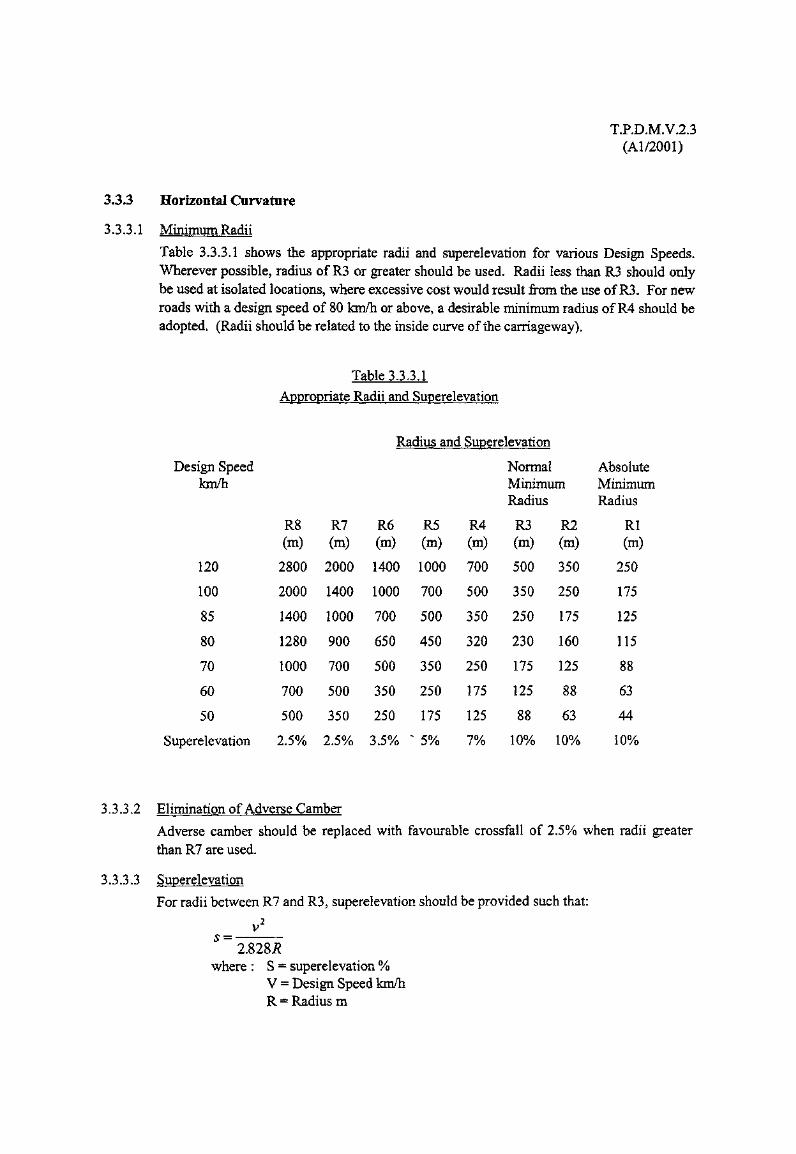
Table 3.3.3,1 shows the appropriate radii and superelevation for various Design Speeds.Wherever possible, radius of R3 or greater should be used. Radii less than R3 should onlybe used at isolated locations, where excessive cost would result from the use of R3. For newroads with a design speed of 80 fcm/h or above, a desirable minimum radius of R4 should beadopted. (Radii should be related to the inside curve of the carriageway).
Table 3.3.3.1
Appropriate Radii and Superelevation
Design Speedkm/h
Radius and Superelevation
Normal AbsoluteMinimum MinimumRadius Radius
120
100
85
80
70
60
50
Superelevation
R8(m)
2800
2000
1400
1280
1000
700
500
2.5%
R7(m)
2000
1400
1000
900
700
500
350
R6(m)
1400
1000
700
650
500
350
250
2.5% 3.5% "
R5(m)
1000
700
500
450
350
250
175
5%
R4(m)
700
500
350
320
250
175
125
7%
R3(m)
500
350
250
230
175
125
88
10%
R2(m)
350
250
175
160
125
88
63
10%
Rl(m)
250
175
125
115
88
63
44
10%
3.3.3.2 Elimination of Adverse Camber
Adverse camberthan R7 are used.
3.3.3.3 Superelevation
For radii between
should be replaced with favourable crossfall of
R7 and R3, superelevation
2.5% when radii greater
should be provided such that:
v2
2.828^where : S = superelevation %
V = Design Speed km/hR = Radius m

T.P.D.M.V.2.3(Al/2001)
For Radii below R3, however, which should only be used at difficult locations, a maximumsuperelevation of 10% should be maintained, together with suitable road surfacing to ensureadequate skid resistance. However, 10% superelevation should be avoided if there is apossibility of stationary or slow moving heavy goods vehicles. For new roads with a designspeed of 80 km/h or above, a desirable maximum superelevation of 7% in conjunction witha desirable minimum radius of R4 should be adopted, together with a suitable road surfacingto ensure adequate skid resistance.
3.3.3.4 Superelevation or Urban Roads
Roads in built up areas with at-grade junctions and accesses should not be superelevated toosteeply, and should preferably not exceed 4-5%. Where the use of radius between R5 andRl is made necessary by severe constraints on the alignment, superelevation should belimited to 5% together with suitable road surfacing to ensure adequate skid resistance.
T.P.D.M.V.2.3(Al/2001)
3.3.4 Transitional Design
3.3.4.1 Superelevation should not be introduced, nor adverse camber removed, so gradually as tocreate large almost flat areas of carriageway, nor so sharply as to cause discomfort or to kinkthe edge of the carriageway. Generally, the carriageway edge profiles should not vary ingrade by more then 1%, and to ensure satisfactory drainage, a minimum longitudinalgradient of 0.67% should be maintained through the transitional area. However, in somedifficult areas, even the above requirements can cause drainage problems, and it may benecessary to increase the variation in grade of the edge profile, or apply a rolling crown in asimilar manner to that required for a level or near level road.
3.3.4.2 In general, the transition curve to be used is clothoid, as described in the HighwayTransition curve tables (metric) compiled by the County Surveyors Society (1963). Undernormal design conditions, it should be possible to apply the superelevation within thetransition length, and satisfy the dual criteria that:
(i) The superelevation should be applied so that the difference in grade of the two edgeprofiles does not exceed 1%; and
(ii) The maximum rate of change of centripetal acceleration does not exceed 0.3m/sec3.
However, it will frequently be impractical to achieve such long transitional designs in thedense constraints of Hong Kong, as these criteria tend to force contiguous curves apart, andseverely restrict the ability of the road to conform to alignment constraints.
3.3.4.3 On elevated structures where the use of clothoid transitions may create difficulties withcomplex geometry it may be suitable to adopt a circular curve in place of the clothoidtransition provided it can be clearly demonstrated that there would be no significantdifference in alignment.
3.3.4.4 The basic transition length shall be derived from the following formula:
L = V3 /(46.7qR)
where L = Length of transition (m)V = Design speed (km/h)q = Rate of increase of centripetal acceleration (m/secj)
travelling along curve at constant speed VR = Radius of curve (m)
3.3.4.5 Table 3.3.4.1 illustrates the transition length requirements for the various curve radii,together with the appropriate shift. Transition lengths of 1.4V (where V = design speedkm/h) or higher will often place severe limitations in areas of difficulty, and it will benecessary to increase the rate of change of centripetal acceleration to 0.6 or even higherwhere low radius curves occur in close proximity. At the same time, especially on multi-lane highways, it will often not be possible to introduce the superelevation as gradually as1% within the transition, and it may be necessary to increase the variation in edge profile to1 % or even 2%.
3.3.4.6 For ease of design and setting out, the County Surveyors Society Tables provide a range oftransitional spirals and it will be appropriate to adopt the spiral with the nearest RL value tothat required by Table 3.3.4.1.

Radius
T.P.D.M.V.2.3(Al/2001)
Table 3.3.4.1
Transition Lengths
Rate of Change of Centripetal Acceleration(with Shift in Bracket)
R6
R5
R4
R3
R2
Rl
0.3m/sec3
0.7V(0.2m)
lV(0.6m)
1.4V(1.7m)
2V(4.7m)
2.8V(13.3m)
4V(37.8m)
0.43m/sec3
0.7V(0.3m)
lV(0.85m)
1.4V(2.4m)
2V(6.7m)
2.8V(18.8m)
0.6m/sec3
0.7V(0.4m)
lV(1.2m)
1.4V(3.4m)
2V(9.4m)
0.86m/sec3
0.7V(0.6m)
lV(1.7m)
1.4V(4.7m)
Design Speedkm/h
120
100
85
80
70
60
50
RL Values
123000
71000
44000
37000
25000
15000
9000
86000
50000
31000
26000
17000
11000
6250
62000
36000
22000
18000
12500
7500
4500
43000
25000
15000
13000
8500
5500
3125
3.3.4.7
3.3.4.8
For radii greater than R7, the normal transition designed for 0.3m/sec3 will be insignificantand not generally required. However, where crossfall is being reversed from the adjacentcurve, it may be suitable to provide a transition to apply the superelevation change. In suchcircumstances, longer transitions than normal will often be required to suit thesuperelevation design.
Progressive superelevation or removal of adverse camber should be achieved over or withinthe length of the transition curve from the curve end. Where a transition curve is notprovided, approximately two thirds of the superelevation should be introduced on theapproach, and the remainder at the beginning of the curve.

T.PDJM.V.2.3(Al/2001)
3.3.5 Sight Distance
3.3.5.1 Table 3.3.5.1 shows the sight distances that must be provided on the approaches to andthrough junctions, accesses, weaving sections and points of vehicular and pedestrianconflict, and the aim should be to provide the desirable minimum distance, rather than theabsolute minimum distance.
Table 33.5.1
Sight distances
Design speed Desirable minimum Absolute minimum(km/h) (m) (m)
120 295 215
100 215 160
85 160 120
80 145 110
70 120 90
60 90 70
50 70 50
3.3.5.2 The sight distances should be measured from a minimum drivers' eye height of between1.05 m and 2.0 m to an object height of between 0.26 m and 2.0 m 5 both above the roadsurface. Forward visibility should be provided in both the horizontal and vertical planesbetween points in the centre of the lane nearest to the inside of the curve.
3.3.5.3 Because of the necessity of providing sight distances in accordance with Table 3.3.5.1 andparagraph 3.3.5.1 it follows that junctions and accesses should not be located on sharpcurves, as this would result in extensive widening of verges, cuttings and bridge structures inorder to obtain the required visibility.
3.3.5.4 For locations, not mentioned in paragraph 3.3.5.1, that are away from the vicinity of ajunction or access or weaving section or place of vehicular or pedestrian conflict and whereon the inside of a curve an obstruction, such as cutting slope, retaining wall, noise barrier, orbridge abutment, occurs, appropriate sight distances obtained in accordance with thefollowing, must be provided:
(i) Low speed urban roads
Because there is little or no restriction on pedestrians and accesses along these roadsthe sight distances in accordance with Table 3.3.5.1, measured in accordance withparagraph 3.3.5.2 should be provided.
(ii) Roads having design speeds of 80 km/h or greater and the radius of the bend is lessthan R3
(a) For a 100 km/h design speed or greater a 4 m width must be maintained clear ofobstructions on the inside of the curve, the clearance being measured from theedge of the running carriageway and may include any hard shoulder, marginalstrip or verge.

T.P.D.M.V.2.3(Al/2001)
(b) For 80 km/h design speed, a 3 m width clear of obstructions must be maintained,the width being measured as in (ii)(a) above.
(iii) Roads having design speeds of 80 km/h or greater, and the radius of the bend is R3 orgreater
(a) For a 100 km/h design speed or greater, a 4 m width in accordance with (ii)(a)above, or a width determined from Table 3.3.5.1 measured in accordance withparagraph 3.3.5.2, whichever is the lesser, must be maintained free ofobstructions.
(b) For 80 km/h design speed, a 3 m width in accordance with (ii)(b) above, or awidth determined from Table 3.3.5.1 measured in accordance with paragraph3.3.5.2, whichever is the lesser, must be maintained free of obstructions.
(iv) Roads having design speed of 50 km/h
This design speed in accordance with Table 3.3.2.1 is only appropriate for singlecarriageway roads and therefore sight distances in accordance with Table 3.3.5.1 mustbe provided.
3.3.5.5 Large direction signs, gantry supports or other substantial obstructions should be sited suchthat they do not obscure sight lines, although isolated slim objects such as lamp columns, orsign posts can be ignored. Laybys should wherever possible be sited on striaight or theoutside of curves where stopped vehicles will not obstruct sightlines.
3.3.5.6 For information on, visibility splays required at priority junctions, visibility requirements atroundabouts, and visibility requirements at grade separated interchanges, Sections 4.3.8,4.5.11, and 4.6.6, respectively, of Chapter 4 in this Volume should be consulted.
T.P.D.M.V.2.3(Al/2001)
3.3.6 Gradients
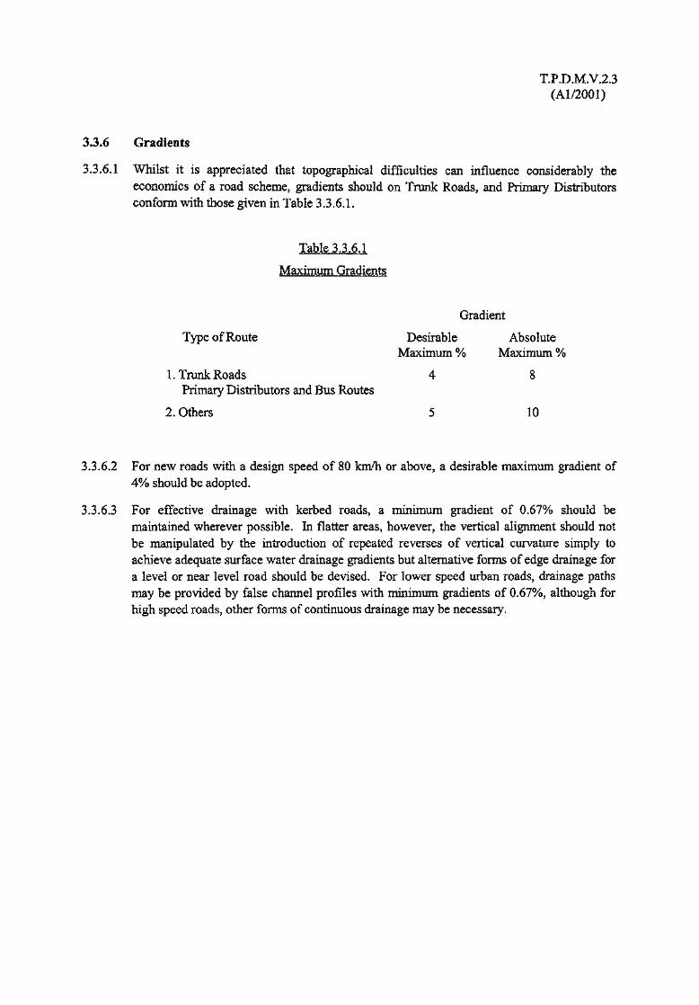
3.3.6.1 Whilst it is appreciated that topographical difficulties can influence considerably theeconomics of a road scheme, gradients should on Trunk Roads, and Primary Distributorsconform with those given in Table 3.3.6.1.
Table 3.3.6.1
Maximum Gradients
Gradient
Type of Route Desirable AbsoluteMaximum % Maximum %
1. Trunk Roads 4 8Primary Distributors and Bus Routes
2. Others 5 10
3.3.6.2 For new roads with a design speed of 80 km/h or above, a desirable maximum gradient of4% should be adopted.
3.3.6.3 For effective drainage with kerbed roads, a minimum gradient of 0.67% should bemaintained wherever possible. In flatter areas, however, the vertical alignment should notbe manipulated by the introduction of repeated reverses of vertical curvature simply toachieve adequate surface water drainage gradients but alternative forms of edge drainage fora level or near level road should be devised. For lower speed urban roads, drainage pathsmay be provided by false channel profiles with minimum gradients of 0.67%, although forhigh speed roads, other forms of continuous drainage may be necessary.
T.PJD.M.V.2.3(Al/2001)
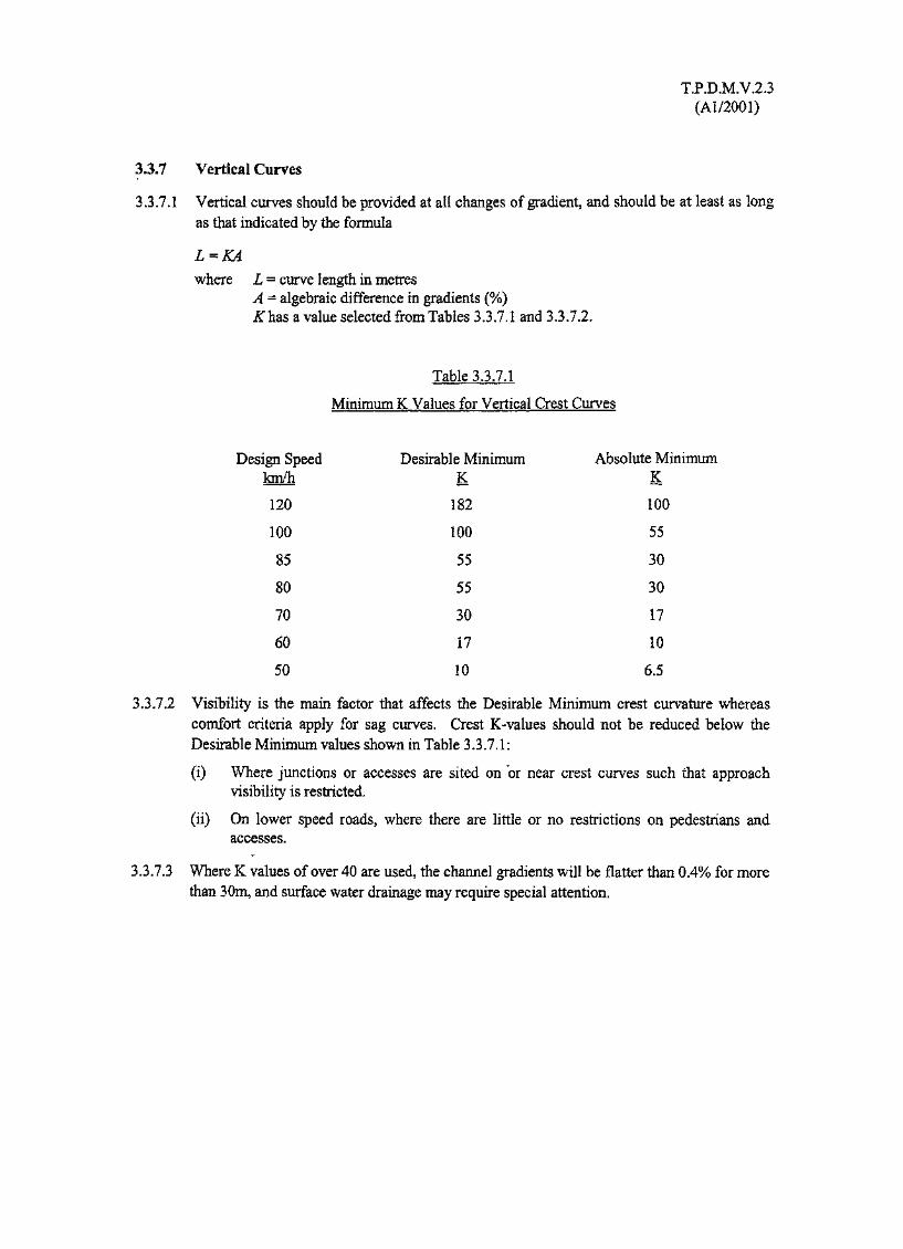
3.3.7 Vertical Curves
3.3.7.1 Vertical curves should be provided at all changes of gradient, and should be at least as longas that indicated by the formula
L=KAwhere L = curve length in metres
A = algebraic difference in gradients (%)Julias a value selected from Tables 3.3.7.1 and 3.3.7.2.
Table 3.3.7.1
Minimum K Values for Vertical Crest Curves
Design Speed Desirable Minimum Absolute Minimumkm/h K K
120 182 100
100 100 55
85 55 30
80 55 30
70 30 17
60 17 10
50 10 6.5
3.3.7.2 Visibility is the main factor that affects the Desirable Minimum crest curvature whereascomfort criteria apply for sag curves. Crest K-values should not be reduced below theDesirable Minimum values shown in Table 3.3.7.1:
(i) Where junctions or accesses are sited on "or near crest curves such that approachvisibility is restricted.
(ii) On lower speed roads, where there are little or no restrictions on pedestrians andaccesses.
3.3.7.3 Where K values of over 40 are used, the channel gradients will be flatter than 0.4% for morethan 30m, and surface water drainage may require special attention.

Design Speedkm/h
120
100
85
80
70
60
50
Table 3.3.7.2
Minimum K Values for Vertical Sag Curves
DesirableMinimum
37
37
26
26
20
20
13
T.P.D.M.V.2.3(Al/2001)
AbsoluteMinimum
37
26
20
20
20
13
9

T.P.D.M.V.2.3(Al/2001)
33.8 Climbing lanes for Single Carriageway Roads
3.3.8.1 Gradients can cause severe congestion on single carriageways, where a slow moving goodsvehicle will create long platoons of traffic if faster vehicles are unable to overtake. Theseplatoons will frequently be unable to dissipate for a considerable distance, as overtaking is adifficult and hazardous manoeuvre on a 2 lane road.
3.3.8.2 When improving an existing single carriageway road, such congested locations will bereadily identified. Significant improvements in flow will be effected by the strategicprovision of climbing lanes at frequent intervals on gradients to permit overtaking where itis most necessary. It is not suitable to provide gradient/traffic criteria for the provision ofclimbing lanes on single carriageways. Each site must be considered individually in relationto overtaking possibilities on the route as a whole, to arrive at the most suitable means ofachieving improvements to traffic flow. In some cases, the provision of a climbing lane on a2-3% gradient may represent the most advantageous means of ensuring that steady progresscan be made.
As an interim measure, the construction of strategically located passing bays should beconsidered where it is likely that a full climbing lane could not be achieved for some periodof time, and the length of the road in question is greater than 500m.
3.3.8.3 For new single carriageway rural roads the provision of climbing lanes on hills offers themost economic and effective means of ensuring that there are frequent opportunities forovertaking and the strategic placing of climbing lanes will ensure steady progress. As withexisting single carriageway roads, it is not possible to provide gradient/traffic criteria andeach site must be considered on its merits in relation to overtaking opportunities on the routeas a whole.
3.3.8.4 The minimum carriageway width at climbing lanes should be 10m, divided into 3 lanes.The climbing lane should be 3.2m wide, the other two being 3.4m each. Appropriate doublewhite line road markings should be in accordance with Volume 3.
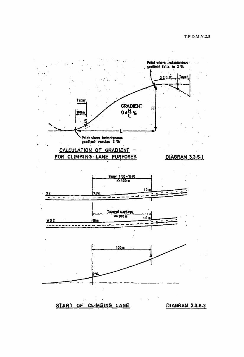
3.3.8.5 Generally, the full width of the climbing lane should be provided at a point "S", 100m uphillfrom the point where the sag curve attains a 2% gradient, as shown in Diagram 3.3.8.1. Ataper of 1 in 30 to 1 in 40 should be provided over the 100m length as in Diagram 3.3.8.2
3.3.8.6 The physical width of the climbing lane should generally be maintained to a point "F", 200mbeyond the point where the crest curve reduces to 2% gradient, followed by a 100m taper.Cross hatching road markings and advance warning signs should be provided in advance ofthe taper, to channelise vehicles.(see Diagram 3.3.8.3).
3.3.8.7 At short hills, it may be necessary to commence the climbing lane in advance of point S soas to provide a minimum length of at least 200m of full width climbing lane. For existingroads, where crest curves may be substantially sharper than the minimum prescribed, it maybe necessary to adopt a shorter terminal detail so as to prevent the lane reduction extendingtoo far beyond the crest.
T.P.D.M.V.2.3
Taper
Point uter* instantaneousfalls to 2 %
• Point vher* Jnstantsnsoosgradient reaches 2 %
CALCULATION OF GRADIENT -FOR CLIMBING LANE PURPOSES DIAGRAM 3,3.8.1
52
START OF CLIMBING LANE DIAGRAM 33.8.2

tft D.M,V. 2.J
10Q1
'Read Arrows'trafficno* 416,
End of Climbing Lane
cDIAGRAM _3.3.e,3
T.P.D.M.V.23(Al/2001)
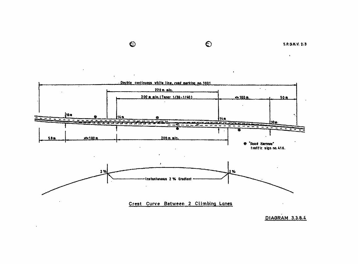
3.3.8.8 At crests, where climbing lanes are provided both sides of the hill and there is less than500m between the ends of the tapers, the climbing lanes should be extended to overlap eachother, providing a four lane carriageway at least 50m long. Continuous double white lines,if not used to separate the opposing lanes on either side of the hill, must be provided acrossthe crest and extend at least 50m beyond the completion/start of the tapers in eitherdirection, as in Diagram 3.3.8.4.
3.3.8.9 Where the climbing lane exceeds 3 km in length it is advisable to provide some sectionswith a straight or large radius right hand curvature as an overtaking section of downhilltraffic.
T,R0,H*V. 23
mOoubit contiimqys white lint, fo8(|
Crest Curve Between 2 Cllmjbing tones
DIAGRAM 3,3.8.4

T.P.D.M.V.2.3(Al/2001)
33.9 CMmbiag Lanes for Dual Carriageway Roads
3.3.9.1 An additional uphill lane should be provided on 2 lane dual carriageway roads if the forecastdesign year traffic flow exceeds the flow level indicated in Diagram 3.3.9.1 relative to thegradient of the hill The Gradient G = 100 H/L should be calculated in accordance withDiagram 3.3.9.1. An additional lane should be considered if the minimum gradient is 3%over a distance of 0.5 km.
3.3.9.2 Where costs of providing the additional land for a climbing lane are high relative to the totalcost of the works, consideration should be given to adjusting the alignment of thecarriageway within the standard highway width and reducing or eliminating theverge/marginal strip widths so that a climbing lane can be provided without any additionalland being required, as shown in Diagram 3.3.9.2.
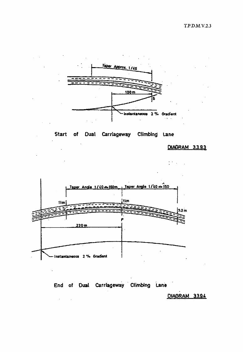
3.3.9.3 The appropriate full width of the climbing lane should be provided in similar manner to thatfor single carriageway, i.e. at a point !IS", 100m from the 2% point of the sag curve.However a taper of at least 1 in 45 should be provided in the case of climbing lanes for dualcarriageways, as shown in Diagram 3.3.9.3
3.3.9.4 At the end of the climbing lane section the extreme left hand lane should be continued, andany tapering down should affect the extreme right hand lane as shown in Diagram 3.3.9.4.
3.3.9.5 Passing bays are not appropriate for dual carriageway roads.

T.P.D.M.V.2.3
0 10,000 20,000 3WJQO SO.DOG
DESK3K YEAI? TRAFFIC FLOW lWO-W«f IAADT)
Dual Carriageway Climbing Lanes Justification
DIAGRAM 3.3.9.1
,1m 7.3m Im.
"* VZBUXUvjL|
m» f.5, t ..1(a) without efsmt»i®s
l.Om
HI
• fb) with ctimfcing lane
CLIMBING LANE PROVISION WfTHlN STANDARD HIGHWAY WIDTH
TP.D.M.V.2.3
Instantaneous 2 % Gradient
Start of Dual Carriageway Climbing lane
Taper I / 40 «a» ISOm„ ..i.JTapgr Ac le I /^40 n 1SD
220m
- Instmotantoos 2 % Gradient
End of Dual Carriageway Ctimbing lane
T.P.D.M.V.23(Al/2001)
3.4. The Road in Cross Section
3.4.1 Cross fall
3.4.1.1 Except on curves where super elevation or elimination of adverse cross fall is required,carriageways should normally have a cross fall of 2.5% from the crown or central reservedownhill towards the side of the road.
3.4.1.2 At the junction of a minor road with a major road the carriageway of the minor road shouldbe graded into the channels of the major road, which should retain its normal cross-sectionthroughout the junction.
T.P.D.M.V.2.3(Al/2001)
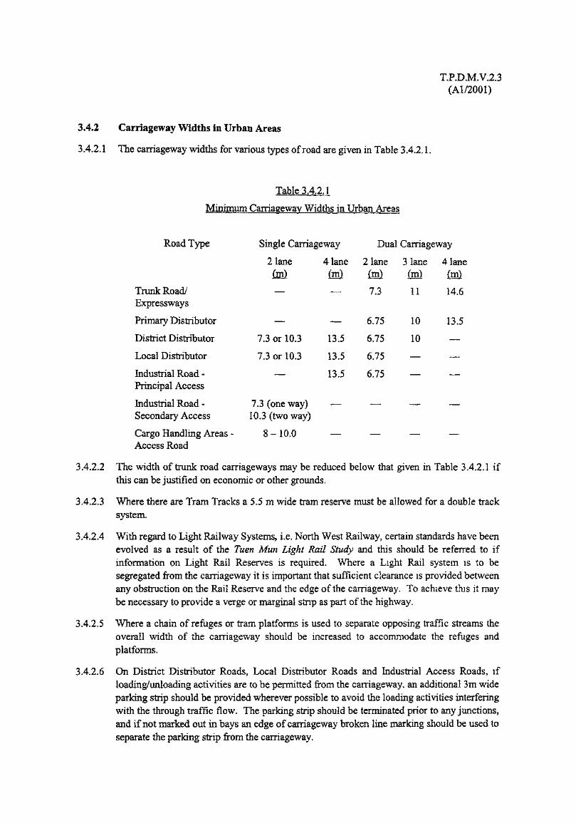
3.4.2 Carriageway Widths in Urban Areas
3.4.2.1 The carriageway widths for various types of road are given in Table 3.4.2.1.
Table 3.4.2.1
Minimum Carriageway Widths in Urban Areas
Road Type Single Carriageway Dual Carriageway
2 lane 4 lane 2 lane 3 lane(m) (m) (m) (m)
Trunk Road/ — — 7.3 11Expressways
Primary Distributor — — 6.75 10
District Distributor 7.3 or 10.3 13.5 6.75 10
Local Distributor 7.3 or 10.3 13.5 6.75 —
Industrial Road - — 13.5 6.75 —Principal Access
Industrial Road - 7.3 (one way) — — —Secondary Access 10.3 (two way)
Cargo Handling Areas - 8-10.0 — — —Access Road
4 laneM14.6
13.5
—
——
—
—
3.4.2.2 The width of trunk road carriageways may be reduced below that given in Table 3.4.2.1 ifthis can be justified on economic or other grounds.
3.4.2.3 Where there are Tram Tracks a 5.5 m wide tram reserve must be allowed for a double tracksystem.
3.4.2.4 With regard to Light Railway Systems, i.e. North West Railway, certain standards have beenevolved as a result of the Tuen Mun Light Rail Study and this should be referred to ifinformation on Light Rail Reserves is required. Where a Light Rail system is to besegregated from the carriageway it is important that sufficient clearance is provided betweenany obstruction on the Rail Reserve and the edge of the carriageway. To achieve this it maybe necessary to provide a verge or marginal strip as part of the highway.
3.4.2.5 Where a chain of refuges or tram platforms is used to separate opposing traffic streams theoverall width of the carriageway should be increased to accommodate the refuges andplatforms.
3.4.2.6 On District Distributor Roads, Local Distributor Roads and Industrial Access Roads, ifloading/unloading activities are to be permitted from the carriageway, an additional 3m wideparking strip should be provided wherever possible to avoid the loading activities interferingwith the through traffic flow. The parking strip should be terminated prior to any junctions,and if not marked out in bays an edge of carriageway broken line marking should be used toseparate the parking strip from the carriageway.

T.P.D.M.V.2.3(Al/2001)
3.4.2.7 The division of two way single carriageways into three lanes, either in the form of two lanesserving one direction and one lane serving the other, or, having a common centre lane usedfor overtaking in both directions, is not appropriate for roads in the Territory and thereforemust not be employed. The reasons for this being that such configurations are potentiallydangerous in respect of:
(i) Where the carriageway is divided into two lanes in one direction and one lane in theother, vehicles in the single lane attempting to overtake slower moving vehicles, evenwhere the double white line system is employed , by moving into the fast lane oftraffic approaching in the opposite direction.
(ii) Where the centre lane is used as a common overtaking lane by traffic in bothdirections, vehicles overtaking slower vehicles moving into the path of vehiclesovertaking in the opposite direction.
(iii) Vehicles making right turns from premises fronting the road having to anticipate atthe same time, both, gaps in the lane or lanes of traffic immediately adjacent to theirside of the road, and gaps in the lane or lanes of traffic in the opposite direction.
(iv) Vehicles making right turns into premises fronting the road obstruction traffic behindthem, and in the case of turning from the single lane, because this will bring allfollowing traffic to a halt, causing the turning driver to attempt to negotiate gaps inthe opposing traffic which are too small, and in the case of vehicles turning from thetwo lane direction being in the path of faster moving traffic which have been usingthis lane to overtake slower moving traffic.
3.4.2.8 The exception to paragraph 3.4.2.7 will be in the situation where on a steep gradient, anadditional climbing lane is required to be provided in accordance with section 3.3.8 of thischapter. However in urban areas, roads of this nature will often have frontage developmentwith access being required into and out of premises at frequent intervals, and also vehiclesstopping to service such premises. If the latter is the case, and right turning pockets cannotbe provided to protect turning traffic in both directions and/or stopping restrictions cannotbe imposed, then it is preferable to have an extra wide two lane carriageway.
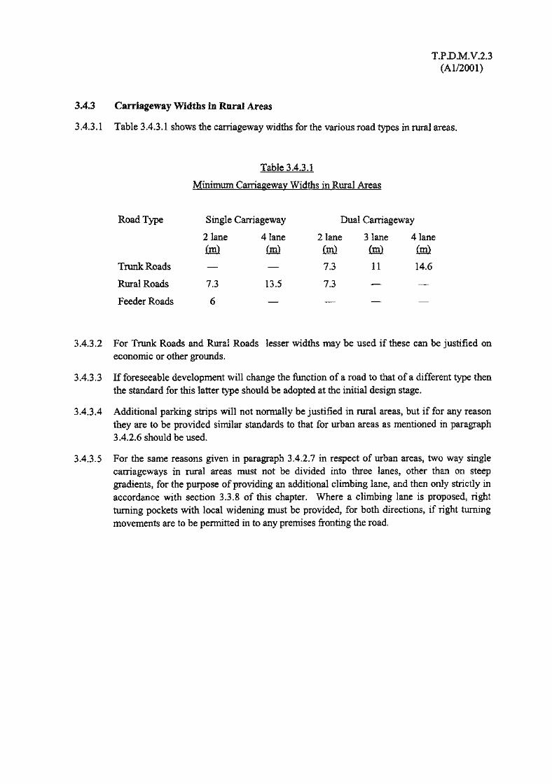
T.PD.M.V.2.3(Al/2001)
3.4.3 Carriageway Widths in Rural Areas
3.4.3.1 Table 3.4.3.1 shows the carriageway widths for the various road types in rural areas.
Table 3.4.3.1
Minimum Carriageway Widths in Rural Areas
Road Type
Trunk Roads —
Rural Roads 7.3
Feeder Roads 6
Single Carriageway
2 lane 4 lane
13.5
Dual Carriageway
2 lane 3 lane 4 lane(in) (m) (m)
7.3 11 14.67 3
3.4.3.2 For Trunk Roads and Rural Roads lesser widths may be used if these can be justified oneconomic or other grounds.
3.4.3.3 If foreseeable development will change the function of a road to that of a different type thenthe standard for this latter type should be adopted at the initial design stage.
3.4.3.4 Additional parking strips will not normally be justified in rural areas, but if for any reasonthey are to be provided similar standards to that for urban areas as mentioned in paragraph3.4.2.6 should be used.
3.4.3.5 For the same reasons given in paragraph 3.4.2.7 in respect of urban areas, two way singlecarriageways in rural areas must not be divided into three lanes, other than on steepgradients, for the purpose of providing an additional climbing lane, and then only strictly inaccordance with section 3.3.8 of this chapter. Where a climbing lane is proposed, rightturning pockets with local widening must be provided, for both directions, if right turningmovements are to be permitted in to any premises fronting the road.

T.P.D.M.V.2.3(Al/2001)
3.4.4 Widening on Curves
3.4.4.1 Where curves of radius of 400m or less are used carriageway widths should be increased inaccordance with Table 3.4.4.1.
Table 3.4.4.1
CurveRadius
<150
150<300
300<400
3.4.4.2 The widening should be achieved by increasing the width at a uniform rate along the lengthof the transition curve on the inside of the curve.
3.4.4.3 Lane widths for slip roads at curves will be given in the relevant section on Junctions.
Appropriate
6m
7.3
7
6.9
Carriageway Widths on
2 lane
6.75m 7.3m
7.9
7.3
7.3
7.9
7.3
7.3
10.3m
11.9
11
10.3
3
10m
11.9
11
11
Curves (m)
lane
llm
11.9
11
11
4
13.5m
15.8
14.6
14.6
lane
14.6m
15.8
14.6
14.6

T.P.D.M.V.2.3(Al/2001)
3.4.5 Service Roads
3.4.5.1 Table 3.4.5.1 indicates the carriageway widths to be used for service roads.
Table 3.4.5.1
Carriageway Widths of Service Roads (m)
Carriageway Type Cars Only All Vehicles
One Way 4.5 5.5
Two Way 5.5 6.75
Industrial Fire Escape & Rear Service Road — 7.3
3.4.5.2 For service roads less than 6m in width, an overall width, when clear of any obstructions, ofat least 6m, but which may include adjacent kerbs, footways or verges, must be provided toallow fire service appliances to operate in the event of emergency.
3.4.5.3 Service roads, which are sometimes provided to reduce the number of points of access on toa major road, should only be considered when the alternative of providing a rear access roadsystem connecting to the major road through proper junctions is found to be impracticable.Where such service roads are provided careful attention needs to be given to the junctionarrangement of the service road with the main road and any side road as because of therestricted visibility of traffic on the service road these junctions can have a high accidentrisk potential. Consideration should be given to reducing as far as possible likely trafficconflict points.
3.4.5.4 The verge between the main carriageway and the service road should generally be 2 m inwidth and never less than 1.5 m. Additional local widening may be necessary however inthe vicinity of junctions.
3.4.5.5 Fire Escape and Rear Service Roads in Industrial Areas should be 7.3 m in width.
3.4.5.6 Details of turning areas are given in Diagrams 3.4.5.1 & 3.4.5.2. However Chapter 2, andChapter 4 should also be referred to if there is any doubt as to the adequacy of the areas interms of the type of vehicles likely to use them.
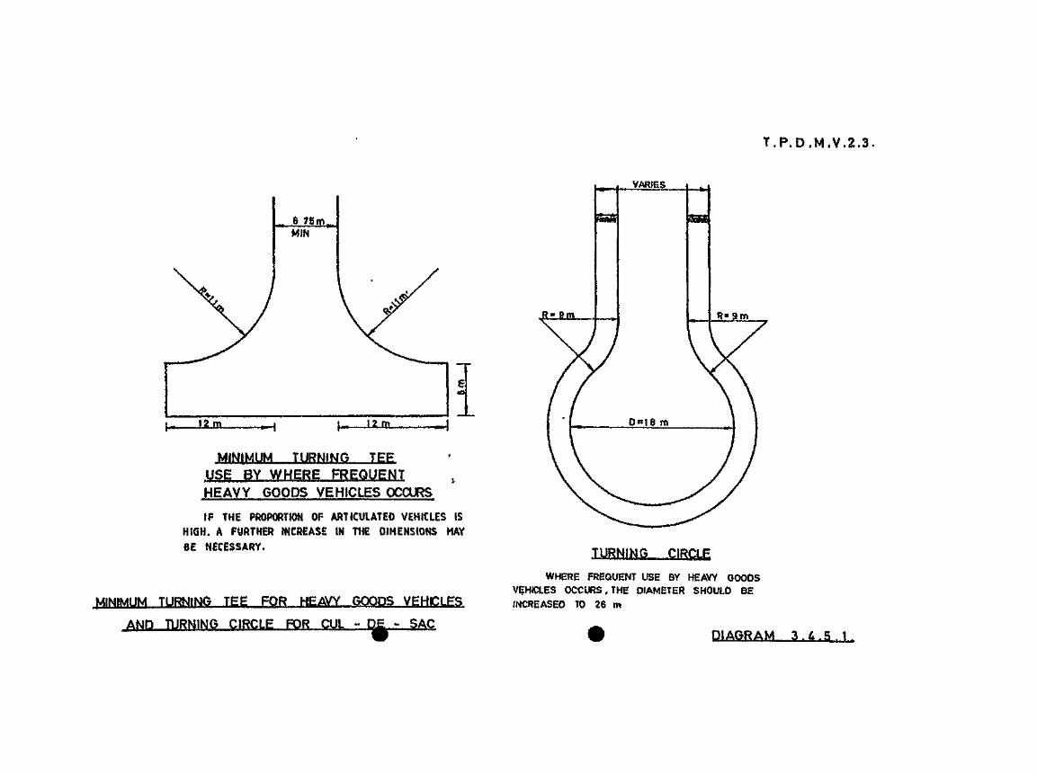

TYPE A
TYPE
FOR LIGHT AND MEDIUM GOODS
DIAGRAM
T.P.D.M.V.2.3(Al/2001)
3.4.6 Cargo Handling Areas
3.4.6.1 The cross section for public cargo working area (PCWA) will depend on the width of thePCWA and the type of cargo to be handled. The minimum width of a PCWA is 50 metres.The arrangement of a cross section is as follows:
Purpose Width (m)
Working apron 10-24
Traffic Lane 8-10
Backing area 12-36
T.P.D.M.V.2.3(Al/2001)
3.4.7 Central Reserves and Traffic Islands
3.4.7.1 On two way roads with four or more lanes it is desirable to separate the opposing trafficstreams by a central reserve. The width of such a central reserve will be dependent on theroad type, the circumstances of the particular location and the type of street furniture to beprovided.
3.4.7.2 In urban areas where barrier fences or other street furniture is not required on the centralreserve the desirable and minimum widths are 1.75 m and 1.25 m respectively.
3.4.7.3 Where road traffic signals are to be installed on the central reserve the actual width will bedetermined by the particular signal arrangement at the location. However, Table 3.4.7.1gives some guidance as to the minimum width requirements.
Table 3.4.7.1
Minimum Widths of Central Reserves
for Road Traffic Signal Installations
Minimum Reserve Width
Size/Type With backing board Without backing boardof Aspects (m) (m)
200 1.65 1.3
300 1.95 1.4
Pedestrian Aspect — 1.5
3.4.7.4 Where overhead traffic signals are to be installed in the central reserve, the appropriatewidth will generally be determined by the diameter of the mast and the horizontal clearancerequirements of section 3.5. However, the width of the concrete foundations may alsoinfluence the position of any kerb surround.
3.4.7.5 If traffic signs are to be mounted on the central reserve normal clearance requirementsshould be maintained. However, some reduction of these in accordance with paragraph3.5.2.2 is acceptable in difficult conditions.
3.4.7.6 On Urban Trunk and Primary Distributor Roads, a minimum 500mm wide marginal stripmust be provided adjacent to each carriageway as part of the central reserve. This widthmay be increased to effect any adjustment to the alignment of the barrier fence provided. Itcan also be assumed for initial design purposes that, the road lighting columns will belocated in the central reserve, and the barrier fence to be provided will be a concrete profilebarrier fence. The minimum width of the central reserve will be determined by the sum of,the marginal strips, the width required for the lighting column or other street furniture andthe width required for the concrete profile barriers. A provisional minimum overall widthfor the central reserve may be taken as 2300mm but this may need to be adjusted dependingon actual mounting details of the lighting columns, gantry signs and traffic signs to allow thestandard horizontal clearance shown in paragraph 3.5.2.1 to be achieved.
T.P.D.M.V.2.3(Al/2001)
3.4.7.7 For Rural Trunk Roads the same considerations as given to Urban Trunk Roads apply to thecentral reserve width, with the exception that the marginal strips should be increased to aminimum width of not less than 1000mm. The minimum provisional central reserve widthfor a Rural Trunk Road, having concrete profile barriers incorporating lighting columns willtherefore be 3200mm, subject to the detailed arrangements for mounting the lightingcolumns and gantry signing Planting in the central reserve of a Rural Trunk Road should beviewed with caution because of the high traffic speeds that can be generated and themaintenance problems and difficulty of access that can result. However if such planting isconsidered appropriate a central reserve width of at least 4000mm will be required. Mosttraffic signs should be able to be accommodated within the 3200mm minimal width withoutthe necessity for further widening.
3.4.7.8 On District and Local Distributor Roads and Rural Roads having dual carriageways thewidth of the central reserve will vary according to the particular circumstances of the route.However in those situations where a concrete profile barrier incorporating lighting columnsis considered appropriate marginal strips not less than 300mm wide must be providedadjacent to the barrier. Based on the provision of concrete profile barriers and lightingcolumns a minimum provisional width for the central reserve may be taken as 1700mm,subject to the detailed arrangements as to mounting requirements for the lighting columns.If planting in the central reserve is required the minimum planting width provided shouldnot normally be less than 1000 mm wide, and it may be appropriate for amenity reasons toreplace the concrete profile barrier with a suitable dwarf wall and kerbs. The marginal300mm strip should however be retained. Where a concrete profile barrier or other barrieris not considered appropriate or necessary paragraphs 3.4.7.2 and 3.4.7.3 will be relevant inrespect of the widths for the central reserve. If traffic signs are required to be erected on thecentral reserves of this type of road the minimum provisions of paragraph 3.5.2.1 must atleast be attained.
3.4.7.9 Consideration should also be given when determining the widths of central reserves as to thefuture requirements, if any, of fixed track mass transit systems and elevated road structures.
3.4.7.10 Careful attention should be given to the termination of central reservations and trafficislands particularly where turning movements may take place, and adequate road markingsand signs in accordance with Volume 3 must be provided in order to direct vehicles past theislands or reservations. For details of barrier fences, refer to Highways DepartmentStandard Drawings.
3.4.7.11 If refuge islands are provided for pedestrians at junctions a minimum width of 4.5 m shouldbe provided on the exit carriageway and 3.8 m on the entry carriageway. The latter mayneed to be increased to 4.5 m if there is a high percentage of heavy goods vehicles.Additionally as shown in Diagrams 3.4.7.1 and 3.4.7.2 the nose of the islands should notgenerally be closer than 3 m to the line of kerbs of the other road forming the junction.
3.4.7.12 Parking should not be permitted in the vicinity of traffic islands or refuges at junctions. It isnot only because of the danger of masking pedestrians crossing the road but also it can resultin vehicles running over the island when manoeuvring past parked vehicles and negotiatingthe junction, causing damage to street furniture or danger to pedestrians waiting on theisland. In many cases it may be necessary to introduce stopping restrictions in the vicinityofj unctions.


T.PD.M.V.2.3(Al/2001)
3.4.7.13 Islands, refuges and central reserves less than 1750 mm in width should be paved. Whetherplanting or similar treatment is appropriate where widths are greater than this will depend onconsiderations mentioned previously, such as the character of the road, the requirements ofpedestrians and the location of street furniture.

T.P.D.M.V.2.3(Al/2001)
3.4.8 Emergency Crossings
3.4.8.1 An emergency crossing may be defined as opening of 10 m in length provided in the centralreservation of a dual carriageway road solely for the purpose of emergency vehicles gainingaccess from one carriageway to another.
3.4.8.2 On high speed road, where speed limit is 70 km/h or above, with limited access and nofrontage development emergency crossings need not be provided unless intersections aregreater than 1.5 km apart. Where this latter condition applies normally only one emergencycrossing will be provided approximately at the mid-point between intersections. If theresulting distance between the intersections and the emergency crossing exceeds 1.5 km,additional crossings may be necessary. However, the emergency crossing should not belocated at the bend of the road for safety reason. To determine the exact location, lengthand number of emergency crossings for a particular scheme, the views of the Police and FireServices Department should be obtained, and where feasible their requirements should betaken into account.
3.4.8.3 For dual carriageway roads other than those described above, emergency crossings shouldgenerally be provided approximately at 600 m intervals, but again the views of the Policeand Fire Services Department should be obtained, as to whether such provision is necessaryor not.
3.4.8.4 Whenever emergency crossings are required care should be taken that they are not sited suchthat they would encourage pedestrians to use them as convenient crossing points. For thisreason they should not be located opposite bus stops, side road junctions or any point ofmajor pedestrian activity.
3.4.8.5 When not in use emergency crossings should be closed by means of suitably designedbarriers which should have been agreed with the Police and Fire Services Department. It isimportant that such barriers can be removed or knocked down rapidly and easily to makeaccess through the crossing in case of emergency. Further, they should be properlymaintained and replaced when damaged.
3.4.8.6 Emergency crossings may not be suitable in their unmodified form to serve as accesses forcontra-flow traffic arrangement should an incident arise, or maintenance work need to beundertaken. In case contra-flow operations are required to be provided in the central barrierduring any incidence or for maintenance purpose, the location and the form of crossovershould be approved by the appropriate Regional Office of the Transport Department inconsultation with the Police and Highways Department.

T.P.D.M.V.2.3(Al/2001)
3.4.9 Verges, Marginal Strips and Hard Shoulders
3.4.9.1 A 3300 mm wide hard shoulder should be provided on all new Expressways. For details,refer to Volume 2 Chapter 6 of this manual.
3.4.9.2 A 3000mm wide verge incorporating a 1000mm marginal strip should be provided on allTrunk Roads with the exception of elevated structures for which a 1000mm nearsidemarginal strip should be provided.
3.4.9.3 On elevated dual carriageway Primary Distributor Roads, a 1000mm nearside marginal stripshould be provided.
3.4.9.4 Marginal strips should be of the same or similar construction as the carriageway, verges maybe suitably hardened.
3.4.9.5 Any barrier fence erected along the nearside verge shall not be closer than 2500mm to theedge of the carriageway.
3.4.9.6 In addition to the other requirements specified in this Chapter, sufficient vertical andhorizontal (up to 5100mm) clearances as shown in Tables 3.5.1.1 and 3.5.1.2 should beprovided for any noise barrier provided along the edge of the carriageway.
3.4.9.7 Kerbs should not be provided on Trunk Roads as far as possible to avoid more severeconsequences caused to errant vehicles when they hit the kerbs. Where kerbs are requiredalong Trunk or Primary Distributor Roads they should normally have a 45° splay and notproject greater than 75mm above the adjacent marginal strip.
3.4.9.8 Attention is drawn to paragraph 3.3.5.2 as in locations where radii below R3 are used it maybe necessary to increase the width of the verge depending on the design speed value. Alsoin the vicinity of the Advanced and Final Advanced Direction Signs, it may be necessaiy toprovide a wider verge if an embankment or cutting can not be utilised. If actual signdimensions are not known a width of 7m from the back of the marginal strip may be taken asa reasonable estimate of the space required, including the minimum horizontal clearance, forAdvanced Direction Signs on roads with a Design Speed greater than 80 km/h.
3.4.9.9 On single carriageway elevated roads of whatever type the highway cross section shouldinclude for a 1000mm marginal strip on one side and a 500mm marginal strip on the other.

T.P.D.M.V.2.3(Al/2001)
3.410 Police Observation Platforms
3.4.10.1 Police observation platforms are raised areas provided for police vehicles to park clear ofthe carriageway and hard shoulder in order to:
(i) monitor traffic flow;
(ii) improve surveillance procedures;
(iii) reduce response time to incidents on the road;
(iv) provide a police presence and thereby improve compliance by road users of trafficregulations;
(v) provide easy access to the main carriageway for enforcement purposes;
(vi) provide an area off the carriageway where if necessary offending motorists can beinterviewed.
3.4.10.2 Police observation platforms should be provided at approximately 2 km intervals on eachcarriageway on all Rural Trunk Roads of 5 km or more in length. A staggered arrangementshould always be adopted so that the distance between alternate platforms is normally about1km.
3.4.10.3 The location of the platforms will need to be determined in consultation with the Police,which should take place at an early stage in the design procedure. The exact location of theplatforms however may not be able to be agreed until the construction stage has beenreached when obstructions to visibility can be identified, and will have regard to thefollowing:
(i) additional land take over can be minimised;
(ii) where platform construction costs can be minimised e.g. at changeover pointsbetween cuttings and embankments;
(iii) maximum unobstructed visibility in both- directions from the platform can beprovided. Visibility requirements will be related to the spacing of platforms andwhere possible intervisibility between alternate platforms is advantageous. If notpossible either by reason of intervening obstructions or the spacing of platforms isnecessarily greater than that given in paragraph 3.4.10.2, a visibility distance of atleast 0.8 km in both directions is desirable and priority should be given to theupstream view. But lesser visibility distances below 0.4 km are not acceptable ;Where a platform is to be used in conjunction with a speed detection system,downstream visibility can be shortened to a distance of 0.8 km.
(iv) if emergency crossings are provided, the platform should be located upstream of thecrossing to ensure that the police vehicles can safely reach it. The platform shouldnot however be located downstream of the emergency crossing as it involves amanoeuvre against the flow of traffic for the police to reach the crossings;
(v) where an emergency telephone system is provided it is advantageous to have theplatform sited near the telephone. However the telephones should not be sited withinthe limits of the platform as it will encourage vehicles other than those of the police touse the platforms;

T.P.D.M.V.2.3(Al/2001)
(vi) there are certain advantages such as the early detection of unsafe or overloadedvehicles, in siting platforms near slip roads where major diverging, merging orweaving movements take place;
(vii) other factors that may also need to be taken into account are:
(a) Suitable radio reception qualities.
(b) Whether the site could be affected by high cross winds.
(c) Platforms should not be sited where the vehicles using them would overlook theprivacy of residential property adjacent to the carriageway.
3.4.10.4 Where part of the rural trunk road route is provided with a closed circuit televisionsurveillance system, such as in tunnel areas, police observation platforms are not required,though it may be necessary depending on the available verge and marginal strip width toprovide lay-bys for enforcement purposes at strategic locations.
3.4.10.5 On Rural Trunk Roads less than 5 km in length, Urban Trunk Roads and Primary DistributorRoads, police observation platforms are not necessary unless the police make a particularrequest and the platforms can be justified as part of the necessary surveillance requirements.Lay-bys at suitable intervals may be considered if the verge and marginal strip widths isbelow that required for enforcement purposes.
3.4.10.6 Where police consider the spacing mentioned in paragraph 3.4.10.2 is not required or siteconstraints make such spacing difficult or expensive to achieve a wider spacing may beadopted.
3.4.10.7 Diagram 3.4.10.1 shows the typical layout of the platform and particular points to note are:
(i) patrol vehicles must be able to park at right angles to the traffic flow;
(ii) the exit should be tapered to the rear of the marginal strip;
(iii) the platform should not be less than 1m above the adjacent carriageway;
(iv) "Police Only, HHFHW, should be marked on the surface of the entrance run-in,facing on-coming vehicles, and on the platform;
(v) construction details must be in accordance with Highways Department standards;
(vi) drainage must be provided in accordance with Highways Department requirements.

T. RD.H.V.
ELEVATION
PLAN
SECTION X-X
POLICE OBSERVATION P L A T F O R M
DIHfHSIONS IN NITRES DIAGRAM 3.4.10.1

T.P.D.M.V.2.3(Al/2001)
3.4.11 Footways
3.4.11.1 Footways should be sufficiently wide to minimise any tendency for pedestrians to walkalong the carriageway.
3.4.11.2 Footways should be constructed with crossfalls between 2% and 3.3% so that they areneither too difficult to drain, nor on the other hand so steep as to make it dangerous to walkupon.
3.4.11.3 The minimum effective widths of footways according to pedestrian volume and type offrontage development are given in Table 3.4.11.1.
Table 3.4.11.1
Minimum Width of Footways
Location
Urban
Industrial
Rural
Width(m)
2.0
2.75
3.5
4.5
3.5
PedestrianVolume
(Ped/Min)
75
115
150
150-200
150
Main FrontageDevelopment
Residential Low Density
Residential Medium Density
Residential High Density
Commercial and in front of Cinemas
Adjacent to principal and secondary Access Roads
A minimum 1 .6m footway should be provided wherever there is a pedestriandemand. In villages, at bus stops and other similar locations, provisionshould be as for the similar frontage in an Urban Area.
3.4.11.4 The minimum footway capacity may be taken as 50 persons per metre width per minute afterdeducting 1 m on shopping frontages and 0.50 m elsewhere for dead areas. However even atthis level of flow free passage can be described as "inconvenient".
3.4.11.5 Additional widths over those in Table 3.4.11.1 will be necessary if amenity planting, streetfurniture, utilities, noise mitigation measures and/or other landscaping features are required.Furthermore, more space should also be allowed for anticipated future development alongthe road. However where tree grilles or concrete block tree surrounds are used providingthat a minimum width of footway, not including the tree grilles, of 2m is available theirwidths may be included as part of the effective footway width.
3.4.11.6 In Rural Areas, it is preferable to separate footways from the edge of the carriageway by a1.25 m verge.
3.4.11.7 In the vicinity of bus stops the footway widths shown in Table 3.4.11.1 should be increasedby at least one metre wherever possible, to accommodate the shelter, and particularly wherepeak flows exceed those given in Table 3.4.11.2.

T.P.D.M.V.2.3(Al/2001)
Table 3.4.11.2
Level of Flow when Additional Footway Width
is required at Bus Stops and Taxi/PLB Stands
Frontage Development Flow (Ted/Min)
Residential Low Density 30
Residential Medium 60Density
Residential High Density 85
Commercial 85
3.4.11.8 The provision of covers to walkways would shield passing pedestrians from rainfall orsunshine. In deciding whether the cover is required, the following criteria should beconsidered.
(i) The walkway should be a main pedestrian link, connecting the major public transportfacilities including railway terminals/stations, ferry terminals and major publictransport interchanges, and the nearest developed or development areas or existingcovered pedestrian facilities etc.
(ii) The pedestrian flow using the walkway should be at least 4,000 ped/hr for not lessthan 3 hours per weekday.
(iii) The provision of cover may be considered when the length of walkway does notexceed 500 m taking account of the general acceptable walking distance, steepness ofthe walkway and the cost of the provision.
3.4.11.9 In the design of the covers for the walkway, considerations should be given to the followingfactors:
(i) The cover should not by itself form any obstruction to fire fighting, rescue or otheremergency operation that may be required at or near the walkway. Hence, theproposed cover and material to be used should be designed to the satisfaction of theDirector of Fire Services and the Director of Highways.
(ii) The proposal should be vetted by the Advisory Committee on the Appearance ofBridges and Associated Structures (ACABAS) for aesthetic consideration. The needfor the provision of a covered walkway should be evaluated against its future impacton the street scene, taking account of street trees and other roadside landscape.
(iii) If utilities on walkway are so congested that adequate construction of cover cannot beprovided, Highways Department should be consulted regarding their possiblediversion.
(iv) The proposed cover should not span over road junctions or run-ins in view of theheadroom and structural problems.
(v) After installation of cover, the clear width of the walkway should not be less than 3m.For very wide walkway, the width of cover to be provided has to be decided onindividual basis.

T.P.D.M.V.2.3(Al/2001)
(vi) Advice from District Office should be sought on comprehensive public consultationof the proposal.
(vii) Priority should be given to locations where there is little opportunity, such as beneathexisting canopies, for the public to shelter along the remaining route .

T.P.D.M.V.2.3(Al/2001)
3.4.12 Typical Cross Sections
3.4.12.1 Diagrams 3.4.12.1 to 3.4.12.8 illustrate cross sections for the following road types:
(i) Urban and Rural Trunk Roads
(ii) Primary Distributor Roads
(iii) District and Local Distributor Roads
(iv) Rural Roads
(v) Elevated Single Carriageway Roads
(vi) Feeder Roads
(vii) Service Roads, and
(viii) Industrial Access Roads
3.4.12.2 Whilst the cross sections are intended to represent typical situations, it may well benecessary to adjust certain of the dimensions to suit the particular circumstances, thoughvery localised adjustments, other than in respect of widening on sharp curves, should beavoided wherever possible.
3.4.12.3 Dimensions which should be regarded as minimal and therefore not subject to any furtherreduction are those for marginal strips and carriageway widths, though in the case of thelatter some reduction in respect of Rural Trunk Roads and Rural Roads may be acceptable.For further details on this and on the other components which form the total road width therelevant sections should be consulted.
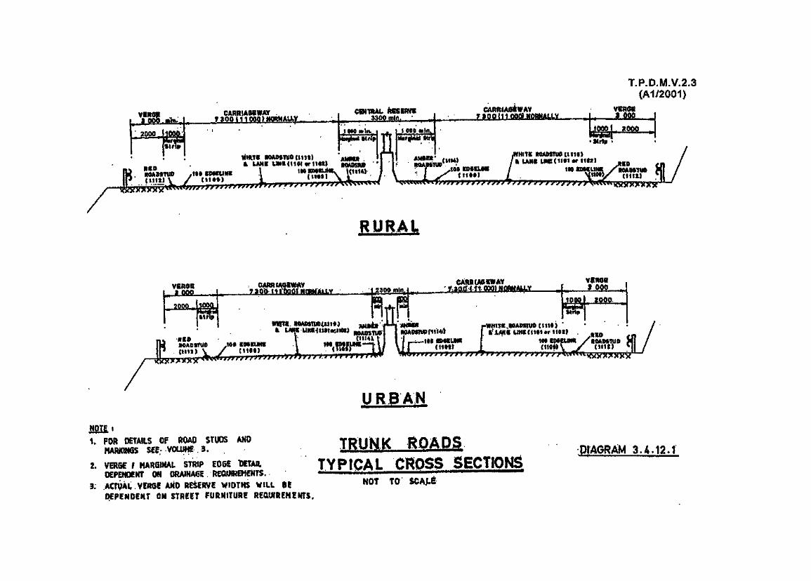

T.P.D.M.V.2.3(A1/2001)
7SO OR 1Q OOP MQftMALLY
PRIMARY DISTRIBUTOR ROADROADATUD(1112)
CAI^iAGSWAY
NOTE:1. FOR DETAILS OF ROAD STUDS AND
MARKINGS SEE VOLUME 3.2. ACTUAL CENTRAL RESERVE WIDTH
WILL BE DEPENDENT ON STREETFURNITURE REQUIREMENTS.
3. MARGINAL STRIP IS ONLY PROVIDEDFOR DESIGN SPEED/SPEED LIMITGREATER THAN 50 km/h
4. FOR DETAILS OF FENCE BARRIERS,SEE SECTION 3.9.3
ELEVATED ROAD
PRIMARY DISTRIBUTOR ROADSTYPICAL CROSS SECTIONS
NOT TO SCALE
DIAGRAM 3.4.12.2

FOOTWAY-fim
(SEE SECTION 3.4.7.6)
«fra&u
syt 4 ate§&•
Halted, in* *Strip *Hj«»A«
i kniiit.
ft*c«m\
i
T.P.D.M.V.2.3(A1/2001)
• ^ manutfi iw **"-******-<*, \^^^^
\Ctftu . .11 Ifll. V _ _ J. aitffl,.ll».3liinrryryryrryTTT^^Ti '
DISTRICT AND LOCAL DISTRIBUTOR ROAD^WT T0
(SEE SECTION 3.4.7.8)
c ffrtiM./Wi^f^4_L ^ & j*kn
NOT TO SCAU
fifiH •1. THE citfTHAi mmix iAimtEa HAY «
HEi uaD iv A surtAit.! m^M>mii AH& icias BUT THIMAftfilNAL 'STRIP SHOULD i
t. QH LOCAL DSTHIIIUTOi HOAOS !AH AODdlOHAl 1 @00PARKSHG WIDTH HAT Bf PHOVl&iO OH QHf OR BOTH
t . ACTUAL CENTRAL HISiRVi W«>TH WILL @E OfPENDiNT• : SIRf IT rURNlTUItf RIQUIfliHf NTS, .
DUAL ROADS TYPICAL SECTIONSDIAGRAM 3.4.12.3
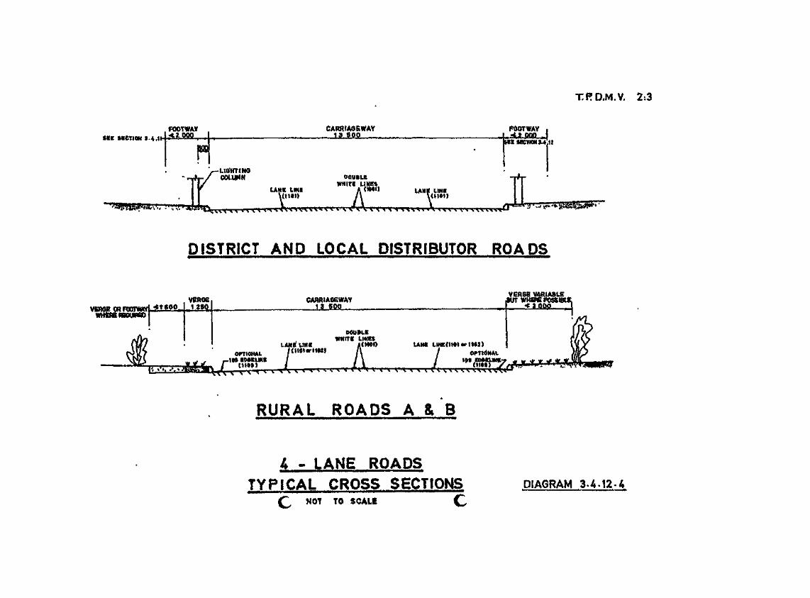
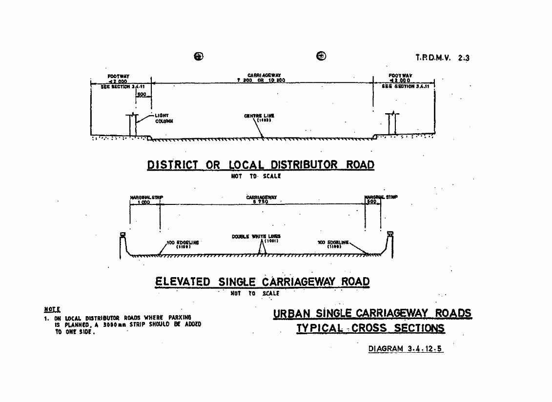
T.RD.M.V.
rwwi¥f«%i
** SE6 SEOTtQtl 3j441L f too on 10 aoo ^ ^t.OOO i
rCOUIMM
^^^^-^r^TTT^rrr'TtTV^
tlNlUHttl
jQrT^r^" *
DISTRICT OR LOCAL DISTRIBUTOR ROADMOf TO-
f^t^^Atsm^ •
.
i&miii
3 DOUBLE WHIT6 U^K M| .100 lOQiUNt Anwi ^5 gixnuNi I II / <$t«t> A cttt&j X, I 1
X^^^^^^ I
ELEVATED SINGLE CARRIAGEWAY ROADNOT TO SCALE
flOTE1. ON LOCAL DISTRIBUTOR ROADS WHERI PARKING
IS PLANNED, A JOOOam STRIP SHOULD BE ADDEDTO ONE SIDE.
URBAN SINGLE CARRIAGEWAY ROADSTYPICAL CROSS SECTIONS
DIAGRAM 3.A.12-5

T.RD.M.V. 2-3
FEEDER ROAD
RURAL SING^ CARRIAGEWAY ROAM.TYPICAL CROSS SECTIONS.
NOT TO SCALf
DIAGRAM 3 - A - 1 2 - 6

T.RD.M.V, 2,3
(A1/2001)
oaa,
VIR6E CAftRIASiWAY
ALL VEHICLES (ONE WAY)
CSIVTIIB UNI f 1103)
FOOTWAY
I•rrrrfflry > 7' y 7 »rrYTKT*T°TTf^ * " ' • ' . " • - " » * • • ^*C
A^EA OP 03STRU07mN^^ j|_Mfi___
^^j— etist^ uNi 111011
|$E£ SEOTION 3«4.lf ]— — s*!
ALL VEHICLES (TWO WAY)
SERVICE ROADS
TYPICAL CROSS SECTIONSNOT TO SCALE
DIAGRAM 3-4.12.7

13
LANi UHEV,-j i 11011 \ _ . \ _'^yrrrrrrrrTTTTTT*^^ltUUn LINE
--
PRtNCIPAL ACCESS (TWO WAY)
AY
LtOHTCOUI4N
I nun HIM \nCf| 1 til
yrr|l /Tr|l| j |7/ / /T| 7 I / / / i
SECONDARY ACCESS (TWO WAY1
FOOTWAYJLMSU
UOHT
jf.iy.yy -jryy / / / • y
SECONDARY ACCESS (ONE WAY)
CARRIAGE WAY...,. a .Qflo
REAR SERVICE ROAD
T.BD.M.V. 2.3
COiUMN
INDUSTRIAL ACCESS ROADSTYPICAL CROSS SECTIONS
TO SCALE
DIAGRAM 3-4.12.8

T.P.D.M.V.2.3
3.5 Highway Clearances
3.5.1 Vertical Clearances for Structures over Pavements
3.5.1.1 Table 3.5.1.1 gives the minimum vertical clearance to be provided for various structures.The minimum headroom requirements in Table 3.5.1.1 are also the desirable clearances.
3.5.1.2 The clearances given in Table 3.5.1.1. should take into account any street furniture e.g.lighting, traffic signs and signals, which may be attached to the structure.
3.5.1.3 During construction of overhead structures across carriageways clearance may temporarilybe reduced to 4.7 m, but adequate signing of this must be provided in accordance withVolume 3. Lower clearances can be accepted if certain vehicle types are to be prohibited.

T.P.D.M.V.2.3(Al/2001)
Table 3.5.1.1Vertical Clearance for Structures over Pavements
Location
Over, and within 600mm of a carriageway
Over a footway but not within 600mm of acarriageway
In pedestrian subways and enclosedfootbridges
(i) less than 23m in length
(ii) 23m or more in length
In cycle subways or similar
(i) less than 23m in length
(ii) 23m or more in length
Above tramways
Above North-west Railway
Minimum forNew Construction
(m)
5.1
3.5
2.3
2.6
2.5
2.7
5.6
2.3
2.5
2.5
2.5
5.6
Beneath Sign Gantries (m) Beneath North-west Railway Power Wires (m)
When Wires pass underStructures
Must not be less than5.4 m but actual heightwill depend onnegotiation with KCRC
To beMaintained
da)5
3.5
Minimumfor New
Construction
5.5
—
To beMaintained
5.4
—
NormalMinimum
5.6
5.6
Will generally not be less than 5.8m but will depend on method of construction of structure, and be subject toconsultation with KCRC, and clearance of 6m or more may be necessary.
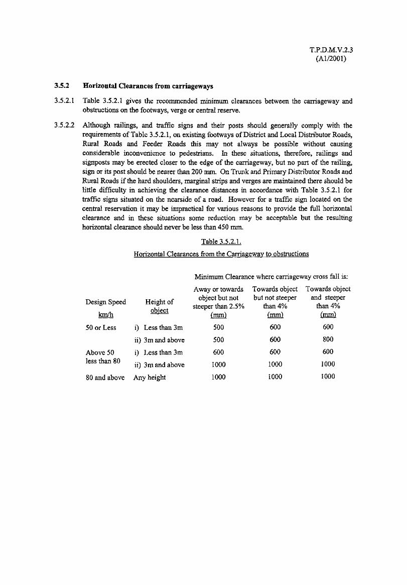
T.PD.M.V.2.3(Al/2001)
3.5.2 Horizontal Clearances from carriageways
3.5.2.1 Table 3.5.2.1 gives the recommended minimum clearances between the carriageway andobstructions on the footways, verge or central reserve.
3.5.2.2 Although railings, and traffic signs and their posts should generally comply with therequirements of Table 3.5.2.1, on existing footways of District and Local Distributor Roads,Rural Roads and Feeder Roads this may not always be possible without causingconsiderable inconvenience to pedestrians. In these situations, therefore, railings andsignposts may be erected closer to the edge of the carriageway, but no part of the railing,sign or its post should be nearer than 200 mm. On Trunk and Primary Distributor Roads andRural Roads if the hard shoulders, marginal strips and verges are maintained there should belittle difficulty in achieving the clearance distances in accordance with Table 3.5.2.1 fortraffic signs situated on the nearside of a road. However for a traffic sign located on thecentral reservation it may be impractical for various reasons to provide the full horizontalclearance and in these situations some reduction may be acceptable but the resultinghorizontal clearance should never be less than 450 mm.
Table 3.5.2.1.
Horizontal Clearances from the Carriageway to obstructions
Design Speed
km/h
50 or Less
Height ofobject
i) Less than 3m
ii) 3m and above
i) Less than 3m
ii) 3m and above
80 and above Any height
Above 50less than 80
Minimum Clearance where carriageway cross fall is:
Away or towards Towards object Towards objectobject but not but not steeper and steeper
than 4% than 4%(mm) (mm)
600 600
600 800
steeper than 2.5%(mm)
500
500
600
1000
1000
600
1000
1000
600
1000
1000

T.P.D.M.V.2.3(Al/2001)
3.6 Run-ins and Footway Crossings
3.6.1 Restrictions
3.6.1.1 Wherever possible run-ins should not be permitted on Trunk Roads, Primary Distributors, orDistrict Distributors. In some instances run-ins may have to be accepted because forexample, existing lease conditions do not provide powers to restrict access, or in new townswhere District Distributor Roads were designed to permit vehicular access.
3.6.1.2 However, where important traffic routes are concerned e.g. trunk roads and primarydistributors, and where the public interest might be severely prejudiced by the opening of arun-in, consideration may be given to applying section 16(l)(h) of the Buildings Ordinance\although such action is almost certain to result in an appeal by the developer.

T.PD.M.V.2.3(Al/2001)
3.6.2 Location of Run-ins
3.6.2.1 General
(i) Run-ins should be sited as far as possible away from junctions, horizontal curves,summit curves, bus stops, zebra or other pedestrian crossings, railway level crossingsand other similar locations.
(ii) Where the lot abuts onto more than one road the run-in should be sited on the leastimportant of these roads.
(iii) For corner lots, it is generally preferable to site run-ins on the downstream side ofjunctions rather than on the approach side (roundabouts excepted).
(iv) Normally there should be not more than one run-in and one run-out, combined orseparate, on any single frontage.
3.6.2.2 Grade Separated Junctions
Run-ins should be avoided at, or in the vicinity of, grade separated junctions, as theysubstantially increase the accident potential. Any exceptions must receive special attentionto ensure that there is no interference with weaving or merging/diverging movements.
3-6.2.3 Signal Controlled Junctions
Run-ins should not normally be sited within 60 m of the stop line on the major road orwithin 45 m on the minor road, on either the approach or exit roads.
3.6.2.4 Roundabouts
Run-ins should not normally be located on the roundabout itself or within 60 m on the exitcarriageway or 45 m on the approach carriageway. In special circumstances these distancesmay be reduced to 30 m and 25 m respectively.
3.6.2.5 Uncontrolled Intersections
Run-ins should be located as far as possible away from an uncontrolled junction andpreferably not closer than 30 m. If there is a likelihood that a junction could be signalised inthe future, the distance should be that appropriate to those for signal-controlled junctions.
3.6.2.6 Horizontal Curves and Summit Curves
Run-ins should not normally be located on horizontal or summit curves. If, however, thiscannot be avoided, then the visibility distance for vehicles approaching the run-in shouldpreferably be appropriate to the Desirable Minimum Sight Distance given in Table 3.3.5.1,and never less than the Absolute Minimum value.
3.6.2.7 Rear Loading/Unloading Lanes
Access should be via a rear loading or unloading lane if one is provided. However, wherethe size of the development is such as to cause overloading of the rear lane, considerationmay be given to access off the public road on to which the lot abuts. On some occasionsaccess from both the rear lane and the public road may be necessary.

T.P.D.M.V.2.3(Al/2001)
3.63 Layout of Run-ins
3.6.3.1 The width of run-ins should be kept to the minimum compatible with satisfactory operationof vehicles using the run-in. The minimum width should be such that a vehicle can enter therun in from the near side lane without encroachment onto an adjacent lane. Where access bycontainer vehicles is required the width should not be less than 7.3 m. Typical layouts forrun-ins are shown on Diagrams 3.6.3.1, 3.6.3.2 and 3.6.3.3.
3.6.3.2 Visibility from a run-in should subject to paragraphs 3.6.3.3, 3.6.3.4 and 3.6.3.5 beobtainable between points 1.05m above the road and run-in level over the area described byABCD in Diagram 3.6.3.4 where:
(i) AC is a line 4.5m in length measured along the centre line of the run-in from thecontinuation of the nearer edge of the carriageway of the road to which the run-in hasaccess, and
(ii) BC and CD, are "x" m in length, and "x" is in accordance with Table 3.6.3.1 and ismeasured along the nearer edge of the road to which the run-in has access.
Table 3.6.3.1
Length of Visibility Line "x"
Design Speed of Main Road (km/h) x(m)
80 or over 150
70 130
60 120
50 60
3.6.3.3 For difficult site conditions the length of the line AC in Diagram 3.6.3.4 may be reduced butshould never be less than 2m. Such reductions however would not normally be appropriatefor Trunk and Primary Distributor Roads.
3.6.3.4 If the road forming the access with the run-in is a dual carriageway road, providing there isno crossing point in the central reserve opposite the entrance or it is a one way road, a singlesplay, defined by ABC or ADC, depending on the direction of approaching traffic, inDiagram 3.6.3.4 would be sufficient.
3.6.3.5 Parking within the vicinity of run-ins should be avoided wherever possible and of courseshould never be permitted across the actual entrance. Ideally parking should be preventedthroughout the length of the visibility splay but on District, and Local Distributor Roads,Rural Roads and Feeder Roads this may not always be possible to achieve.
3.6.3.6 Traffic signs and other street furniture such as lighting columns will often have to be erectedwithin the visibility splays or may in fact, be already erected. This should not be used as areason for not permitting a run-in, unless serious interference with sight lines occurs and it isnot possible to relocate the item of street furniture in question.
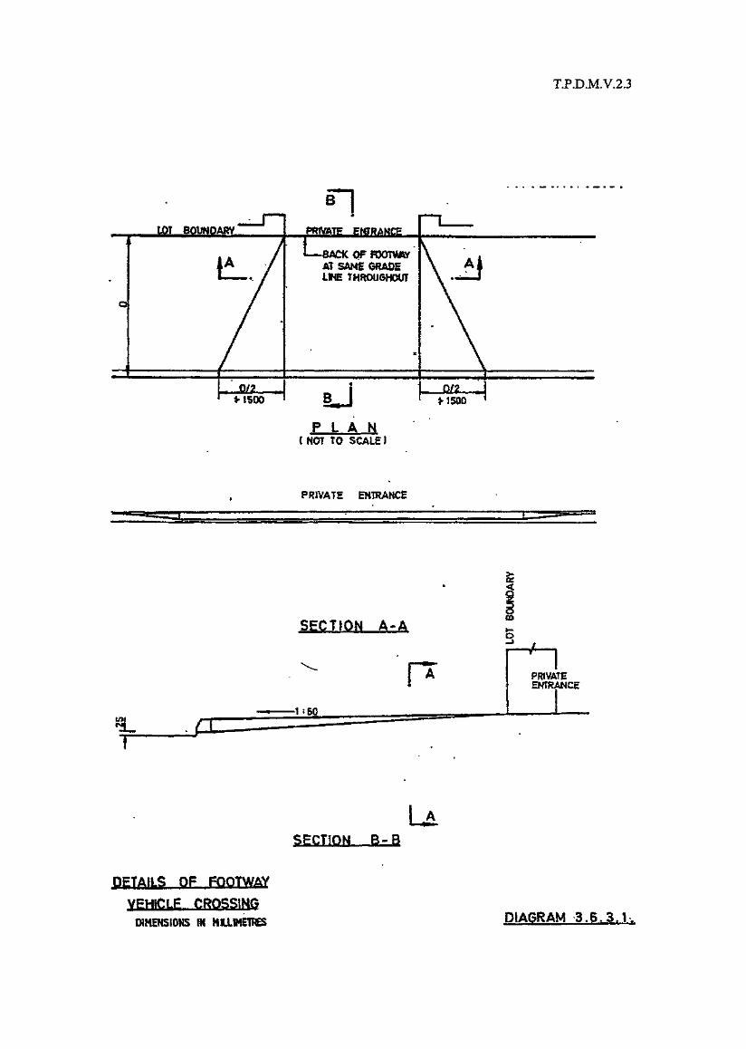
T.RD.M.V.2.3
LOT BOUNDARY PRIVATE EMTftAMOE
BACK OFAT SAMS GRADEISNE THROOSHOUI
0/2 0/2 , j
P L A NC NOT TO SCALE J
PRIVATE EH1HAHCE
SECTION A-A
SgCTfOKi B-B
DETAtLS OF FOOTWAY
VEHlCLg CROSSING
DIMENSIONS (N MIUME1BES DIAGRAM 3.6.3.1

T. P. 0. M. V. 2.3
-iACK OP FOOTWAY At SAME GRADE LINE THROUGHOUT
PRIVATE ENTRANCE
VEHICLE ENTRANCE
NORMAL FOOTWAY PAVING
' / / jfitf1- *$BMINi
NORMAL KER8n
HEIGHT
™ -WA- «OR MAX, 1500
KERB ONI SLOPE
^ KERB HEIGH? 2BABOVE CHANNEL 1
bt%OR MAX. 1500
JKERB ON^P™——^
•
NORMAL KERB^ HEIGHT ~" , ""
ENTRANCEBACK OF FOOTWAY
•TOP OF KERB
ELEVATION OF KERB
FOOTWAY CROSSING FOR VEHICLE
ENTRANCE ( FOR SKEW RUN-IN )
ALL DIMENSIONS GIVEN IN MILLIMETRESDIAGRAM 3.6.3.2

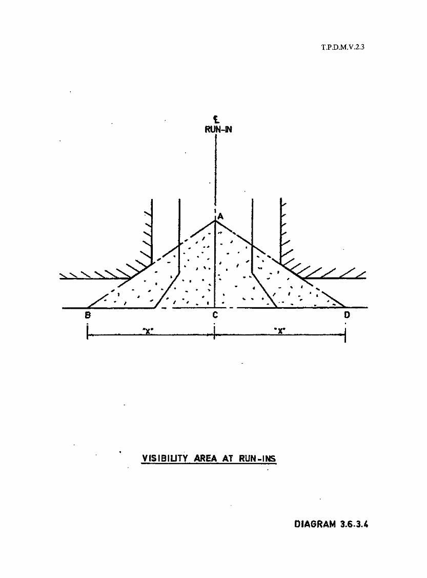
T.P.D.M.V.2.3
t
NXX X
«. I
B
VISIBIUTY AREA AT RUN-INS
DIAGRAM 3.6.3.4

T.PD.M.V.2.3(Al/2001)
3.6.4 Vehicular access to Short Term Tenancy (S.T.T.) Sites and Short Term Waiver(S.T.W.) Sites
3.6.4.1 Because it is impractical to ban vehicular access to all STT or STW sites the followingguidelines should be used when considering whether access is appropriate or not:
(i) Trunk Roads
No direct access from an STT or STW to a Trunk Road shall be permitted,
(ii) Primary Distributors
As a general rule no access direct from an STT or STW; shall be permitted. Directaccess will only be considered in exceptional circumstances when all other possibleaccess provisions have been examined and proved impractical. Even then directaccess may only be approved if general traffic engineering conditions such as theavailable sight lines, distance from junctions or pedestrian crossings etc, taking intoaccount the speed and volume of existing or predicted traffic, are acceptable.
(iii) District Distributors
As a general rule direct access from an STT or STW should be avoided if possible.Direct access will be considered for large sites only if other access provisions havebeen examined and proved impractical. Even then direct access may only beapproved if the location is such that general traffic engineering conditions such as, theavailable sight lines, distance from junctions or pedestrian crossings etc, taking intoaccount the speed and volume of existing or predicted traffic, are acceptable. Thematter of predicted traffic flow in new towns is particularly important as thoughtraffic may be light at the time the matter is under consideration the situation couldchange rapidly as development proceeds and therefore careful consideration must begiven in order not to create precedents or situations which could later prove difficultto cater for.
(iv) Local Roads
Direct access from an STT or STW may be approved if the location is such thatgeneral traffic engineering conditions such as the available sight lines, distance fromjunctions or pedestrian crossings etc are acceptable.
(v) Motorable Tracks (not maintained by Highways Department')
Before agreeing to direct access from an STT or STW consideration should be givento the following factors:
(a) Size and nature of the proposed STT or STW sites e.g. (factories or storagearea).
(b) Width of the existing track. STT or STW sites should not be considered onsingle track roads of inadequate width or where the provision of passing bays atsuitable intervals is not possible due to site constraints, including structures orprivate land.

T.P.D.M.V.2.3(Al/2001)
(c) Need for road improvements. Each case has to be considered on its merits andin some cases it may be necessary to carry out some minor road improvementsbefore such sites can be accepted.
(d) General traffic engineering conditions, such as available sight lines, distancefrom junction etc.
3.6.4.2 In the detailed assessment of the location of an access to S.T.T. or S.T.W. sites the trafficengineering aspects referred to in respect of normal run-in requirements in sections 3.6.1,3.6.2 and 3.6.3 will also be applicable.

T.P.D.M.V.2.3(Al/2001)
3.7 Pedestrian Crossing Facilities
3.7.1 Planning of Pedestrian Crossing Facilities
3.7.1.1 A majority of road accidents happen to pedestrians whilst crossing the road. It is thereforeessential that proper consideration should be given to providing adequate and safe crossingfacilities for pedestrians.
3.7.1.2 Complete segregation of pedestrians from vehicular traffic by footbridges or subways isobviously the most safe form of crossing. It will also have the advantages of betterenvironment, faster vehicle speed and higher road capacity. Therefore, it is important at theoutline planning stage of all new development that proper consideration is given to theprovision of such facilities. Even if grade separated crossings could not be justified at theinitial stages of the development the reservation of land for future provision should be madeif reasonably possible.
3.7.1.3 The important factor in planning for all pedestrian crossings is that the location ensuresmaximum potential usage and is as convenient as possible to defined pedestrian paths.Devious routes to crossing facilities or facilities located too far away from pedestrian routes,will lead, in spite of any railings intended to prevent this, to pedestrians creating their owncrossing points to the detriment of their own and other road users safety.
3.7.1.4 In respect of paragraph 3.7.1.3 Regulation 39 of the Road Traffic (Traffic Control)Regulations does make it an offence for pedestrians to climb through or over any railings,and also to cross the road within 15m of a crossing facility other than at the facility.However it is preferable that such actions be avoided by making the crossing facility themost obvious and direct place to cross rather than relying on police enforcement.
3.7.1.5 Guidance as to what type of crossing facility is most appropriate for a particular location isgiven in subsequent sections.
T.P.D.M.V.2.3(Al/2001)
3.7.2 At-Grade Crossings
3.7.2.1 At-Grade Crossing are of the following types:
(i) Zebra Crossings
(ii) Light Signal Controlled Crossings
(iii) Cautionary Crossing at signal junctions
(iv) Uncontrolled cautionary crossings
3.7.2.2 At all at-grade crossing points dropped kerbs in accordance with Diagram 3.7.2.1 should beprovided to assist the elderly and people with disabilities. The lowered kerbs should beprovided for the full width of the crossing, with the ramped kerbs being located outside thiswidth. Under no circumstances should a dropped kerb be continuous around a corner radiusas this could lead to vehicles running onto the footway when negotiating the corner, but seealso paragraph 3.7.4.10.
3.7.2.3 At-grade crossings should not generally be installed on Trunk Roads or PrimaryDistributors, where pedestrians should be segregated from vehicular traffic. Across PrimaryDistributors serving also as District Distributors consideration may be given to the use oflight signal controlled crossings but no other form of at-grade crossing should be used.
3.7.2.4 The width of at-grade crossings should generally not be less than 2.5m nor greater than 9m.Normally the crossing width will vary between 4m and 6m, as widths less than this havebeen found to be too narrow, and widths greater than this neither possible because of sitelimitations nor desirable because of the effects on vehicle capacity. Width of 2.5m may beappropriate for uncontrolled cautionary crossings.
3.7.2.5 It is important that the crossing width provided is not obstructed by street furniture and thatadequate sight lines for pedestrians are available.
3.7.2.6 Table 3.7.2.1 gives a guide to appropriate crossing widths in relation to expected flows, andalso serves as a first step in the calculation of pedestrian capacity at signal controlledcrossing which is explained in Section 3.7.4. It should however be stressed that pedestrianvolumes in excess of those indicated for a particular width have been recorded and thereforethe table should not be applied rigidly. Volumes in excess of 1200 pedestrians per metrewidth per hour, will generally be difficult for any at-grade crossing to deal withsatisfactorily from both a pedestrian safety and vehicular flow aspect and improvements oralternative means of crossing should be considered when flows are at or above that level.
3 7.2,7 Adequate reservoir space must be provided at the edge of the carriageway and on any centralrefuge, for pedestrians waiting to cross.
3.7.2.8 The following factors should be considered when assessing whether a zebra crossing or alight signal controlled crossing should be provided:
(i) the surveyed pedestrian/vehicle flows conflict;
(ii) the current accident record; and
(iii) the benefits to pedestrians in terms of convenience, safety and reduced delay againstany additional delay incurred by vehicle occupants.


T.P.D.M.V.2.3(Al/2001)
Table 3.7.2.1
Crossing Widths
According to Approximate Pedestrian Flows
Crossing Width Pedestrians Per Hour
(m) Both Directions
2.5 1500 - 3000
4 2400 - 4800
5 3000 - 6000
6 3600 - 7200
7 4200 - 8400
8 4800 - 9600
9 5400 -10800
3.7.2.9 Guidelines for the provision of a zebra crossing and a light signal controlled crossing aregiven in sections 3.7.3 and 3.7.4 respectively.

T.PD.M.V.2.3(Al/2001)
3.7.3 Zebra Crossings
3.7.3.1 The road markings for the crossing and the controlled area are shown in Diagrams 3.7.3.1and 3.7.3.2 respectively. Further information on these markings and how they are formedare given in Volume 3.
3 7 3.2 Zebra crossings have the advantage of being the simplest and cheapest controlled crossing toinstall and operate, generally enabling the pedestrian to cross a road safely and withminimum delay.
3.7.3.3 The disadvantage of zebra crossings is that they may be disruptive to vehicular trafficcausing considerable delays if pedestrian flows are heavy. Therefore, they may also be lesssafe for pedestrians and should not normally be installed in the following situations:
(i) On Trunk Roads and Primary Distributor Roads,
(ii) When the speed limit of a road exceeds 50 km/h.
(iii) When the approach road before the zebra crossing has a downhill gradient of 4% orsteeper for a length of 100m or more.
(iv) When traffic signals on either side of the location of the proposed zebra crossing arelinked or form part of an ATC system.
(v) When the proposed location is at close proximity to a roundabout of small radius.
3.7.3.4 The provision of zebra crossings on District Distributor Roads and Rural Roads should betreated with discretion as conditions such as high vehicle approach speeds or heavy trafficvolumes may not be appropriate for these crossings.
3.7.3.5 The following quantitative criteria may be used, subject to paragraph 3.7.3.6, as a guide towhether a zebra crossing is appropriate or not for roads not affected by the criteria inparagraph 3.7.3.3.
(i) Where a central refuge is not to be provided,
PV2 > 108
where, P = No. of pedestrians per hour averaged over the six highest hours,
and V= No. of vehicles per hour averaged over the six highest hours and is > 600
(ii) Where a central refuge is provided,
PV2>2 xlO8,where P and Fare as defined in (i) but in this case V> 800.

T.P.D.M.V.2.3
INDICATION OF
PEDESTRIAN CROSSING
NOTE.
DIMENSIONS TO BE JN ACCORDANCE WITH REF. ft .
DIAGRAM 3.7.3.1

T.P.D.M.V.2.3
GJVE WAY UNE
o4U«4O
u<§UIKj
TERMINAL LINE
INDICATION... OF
PATTERN OF LINES ON ONE OR BOTH SIDES OF A CROSSINGINDICATING ZEBRA CONTROLLED AREA.
EACH ZIG-ZAG LINE NEED NOT CONTAIN THE SAME NUMBER OF MARKS.
NQTE.
DIMENSIONS TO BE IN ACCORDANCE WITH REFM8. DIAGRAM 3 .7.3.2

T.P.D.M.V.2.3(Al/2001)
3.7.3.6 In rural areas in the New Territories, and in some urban areas, conditions sometimes existwhere the criteria mentioned in paragraph 3.7.3.5 could not be obtained, because of the lowlevel of pedestrian use. However for safety reasons an uncontrolled cautionary crossingwould not he appropriate and therefore in these locations the criteria given in Table 3.7.3.1may be used. Care however should be exercised in the use of the table, and it should beestablished that there is a genuine need for a zebra crossing. Proliferation of zebra crossingsparticularly where pedestrian flows are light may lead to a debasement of the value of thecrossing generally. The possible accident effect as mentioned in paragraph 3.7.3.7 shouldalso be taken into account.
Table 3.7.3.1
Criteria for Zebra Crossings in Rural Areas
Peak hour vehicular volume
Without With Peak HourXT * -T Pedestrian Pedestrian PedestrianNumber of Lanes _ - _ ~ ., tRefuge Refuge Volume
2 lanes 1000 — 70
3 lanes 600 — 70
4 or more lanes 400 1000 70
3.7.3.7 Accident statistics may also be taken into account when considering the introduction of azebra crossing or the change of a zebra crossing to another form of crossing. If detailedanalysis of the accident pattern indicates that inadequate pedestrian crossing, facilities is oneof the contributory factors of the accidents, then these may be used to justify the need for acrossing, or a change of crossing type even though the conditions in paragraph 3.7.3.5 maynot be entirely satisfied. However, research findings in 'The Overall Effect on Accidents atSites where Zebra Crossings were Installed5 of theTJ.K. have indicated that, "the installationof a zebra crossing can achieve a significant reductions in accidents only if the accident rate,prior to installation, is at or above the average. In fact there is a danger that the installationwill have a serious effect, particularly on pedestrians, if there is no definable problem beforethe crossing is installed." Territory conditions are not always the same as those in the U.K.but it would seem worth taking these findings into consideration when deciding the merits orotherwise of installing a zebra crossing.
3.7.3.8 Where vehicular flows averaged over the 6 hours exceed 1000 v.p.h., other forms ofcrossings i.e. light controlled or grade separated may be more appropriate particularly interms of safety and causing less disruption.
3.7.3.9 For existing zebra crossings where peak hour flows are equal to or exceed 1700 v.p.h.consideration should be given to changing the crossing to a light controlled one, or whereappropriate to a grade separated crossing.
3.7.3.10 Appropriate widths for zebra crossings are indicated in Table 3.7.2.1.

T.P.D.M.V.2.3(Al/2001)
3.7.3.11 Desirable Minimum sight distances in accordance with Table 3.7.3.2 should normally beavailable to motorists on the approach to a zebra crossing, and should only in exceptionalcircumstances be less than the Absolute Minimum. Appropriate warning signs should beerected where visibility distances, are at or below Absolute Minimum.
Table 3.7.3.2
Sight Distance for Zebra Crossing
Speed Limit Desirable Minimum Absolute Minimum(km/h) (m) (m)
50 70 50
60 95 70
70 125 95
3.7.3.12 The location of zebra crossing as with other crossings should take account of advice given insection 3.7.1. However particular care should be taken where zebra crossings are locatednear bus stops that stopped buses will not obscure the vision of pedestrians or motorists.Zebra crossings should also be avoided near points where traffic streams merge as themotorists will have difficulty in observing both the traffic to be merged with, and possiblepedestrians on the zebra crossing ahead. At exits From roundabouts particular problemsarise where if the crossing is sited too close to the roundabout vehicles may tail back ontothe roundabout, but if it is located too far away pedestrians may not use it. Each situationwill require individual consideration but generally the crossing should not be located closerthan 20m to the roundabout exit.
3.7.3.13 Zebra crossings impose a number of restrictions on vehicles, which are mentioned in moredetail in Volume 3, and it is important that the implications of these restrictions are takeninto account when proposing the installation of any zebra crossings. A particular point tobear in mind is the stopping restrictions imposed by the Zebra Controlled area and what ifany implications this may have on frontage developments.

T.P.D.M.V.2.3(Al/2001)
3.7.4 Signal Light Controlled Crossings
3.7.4.1 A typical layout of a signal light controlled crossing is shown in Diagram 3.7.4.1.
3.7.4.2 A signal light controlled crossing is more appropriate than a zebra crossing in the following
situations:
(i) where there are significant numbers of elderly and disabled pedestrians;
(ii) where pedestrian and/or vehicle flows are heavy;
(iii) at sites with relatively high approaching speeds;
(iv) at special sites such as contra-flow bus lanes; and
(v) in areas operating under an Area Traffic Control System.
3.7.4.3 The use of staggered crossing should be avoided and CTEs should personally vet andapprove such installations, if absolutely necessary. If such type of crossing is provided, thestaggering should preferably be left-handed so that pedestrians stepping onto the centralreserve or refuge turn towards the approaching traffic to give them a better view of it. Thecentral refuge should be large enough to accommodate the expected numbers of pedestriansgathered during each signal cycle.
3.7.4.4 The pedestrian signal aspects must be so positioned that pedestrians looking at these are alsofacing the approaching traffic as shown in Diagram 3.7,4.1.
3.7.4.5 In the event that the crossing width is excessive, say more than 9 m, it is advisable toconduct a site inspection to ascertain whether the provision of two sets of pedestrian signalsis required.
3.7.4.6 The method of calculating signal timings and similar details are contained in Volume 4 ofthis manual.
3.7.4.7 When the signal light controlled crossing forms part of a signal controlled junction, carefulconsideration should be given to the form and siting of the crossing. Split vehiclemovements in front of pedestrian crossing should be avoided as far as possible as this willmislead pedestrians who may be tempted to cross in front of stopped vehicles. If splitphases have to be provided, channelising islands should be constructed in order to providerefuges for pedestrians to wait. If refuges cannot be provided in these circumstances it ispreferable that the crossing point be relocated.
3.7.4.8 At signal controlled junction with light controlled crossings, vehicle/pedestrian conflictpoints should be checked in addition to checking the vehicle/vehicle conflict points toensure adequate vehicle clearance time before commencement of the pedestrian greensignal.
3.7.4.9 Predicted flows may be taken as the averaged four highest hours. Flows should be measuredover a 50m length in the vicinity of the proposed location of the crossing, unless there is acrossing place already defined. However even with a defined crossing place it may beappropriate to extend the survey area to include pedestrians who may be crossing the roadnear but not on the crossing place.
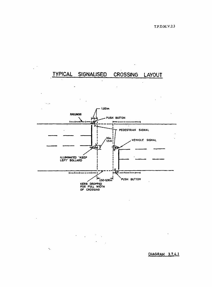

T.P.D.M.V.2.3(Al/2001)
3.7.4.10 The location of the crossing point at signal controlled junctions with a pedestrian phase isimportant on the positioning of the dropped kerb. In many occasions kerbs have beendropped around the complete radius of the kerbs between the major and minor roads.Unfortunately this tends to encourage vehicles to negotiate the curve much closer to the kerbthan they normally would. Therefore, the crossing should be aligned so that the tangentpoint of the radius on the minor road is the point where the kerb is first ramped down toform the dropped kerb. For large radius curves, however, this may mean that the crossing islocated along the minor road footway away from the normal path of pedestrians and withinsufficient reservoir width for pedestrians waiting to cross. In these latter instances thecrossing may be positioned closer to the minor road, but the dropped kerbs should notextend along the circumferences of the kerb radius for more than half its length. However inmany locations there is also an adjacent crossing on the major road and the adjustment ofthe crossing on the minor road can result in the dropped kerbs of both crossings coinciding.If the crossing on the major road cannot be set further back to avoid this, at least 2m andpreferably 3m of raised kerbs should be provided between adjacent crossings.
3.7.4.11 As with other crossings it is essential that there is adequate reservoir space at the side of theroad and within any refuge island provided for pedestrians to wait without encroaching ontothe carriageway and without obstructing the movements of other passing pedestrians.
3.7.4.12 Audible traffic signals must be provided at signal light controlled crossings to assist visuallyimpaired persons. For details of operation hours, refer to Volume 4 Chapter 4.
T.P.D.M.V.2.3(Al/2001)
3.7.5 Cautionary Crossings at Signal Controlled Junctions
3.7.5.1 These are crossing places indicated by studs and incorporated as part of a signal controlledjunction installation, but have no separate pedestrian phase provided. Pedestrians have noright of way at these places but are encouraged to cross "with the light" during the redperiods to vehicular traffic.
3.7.5.2 The use of this type of crossing should be avoided wherever possible and particularly wheresplit phases and relatively high vehicular movements are involved.
3.7.5.3 The disadvantage of this type of crossing is that pedestrians are required to look at the signalheads intended for vehicular traffic to see when it is appropriate to cross. The most visibleone to pedestrians is generally the secondary signal which means that pedestrians will belooking in the opposite direction to which traffic is approaching to their obviousdisadvantage should the signals suddenly change.
3.7.5.4 Where this type of crossing is employed similar consideration to the siting of the crossing asthat for signal light controlled crossings should be given.
3.7.5.5 Appropriate crossing widths may be determined from Table 3.7.2.1.
3.7.5.6 Only studs should be used to delineate the crossing area for these type of cautionarycrossings, any other markings which may be used for signal light controlled crossings arenot appropriate.
T.P.D.M.V.2.3(Al/2001)
3.7.6 Uncontrolled Cautionary Crossings
3.7.6.1 These crossings are only intended to indicate the general path that pedestrians should followwhen crossing a road.
3.7.6.2 Studs or other markings should not be used to delineate or enhance the area of the crossing.The only indications that it is a crossing point should be a dropped kerb and railings to beprovided on both sides of the crossing, and if the carriageway is relatively wide, and subjectto paragraph 3.7.6.6, a pedestrian refuge in the middle of the carriageway.
3.7.6.3 Cautionary crossings should generally only be provided across local or feeder roads, andtheir use should be avoided across dual carriageways wherever possible.
3.7.6.4 Similar considerations as that given to signal controlled crossings, will need to be given tothe siting of the dropped kerbs where the cautionary crossing is adjacent to a junction.
3.7.6.5 Table 3.7.2.1 may be used to determine the appropriate width over which the kerbs shouldbe dropped.
3.7.6.6 Refuges should not be provided unless at least a 3.8m, or 4.5m carriageway if the percentageof heavy goods vehicles and buses is high, can be provided on either side of the refuge.
3.7.6.7 Where a refuge is provided the nose of the island should be set back at least 3m from theedge of the carriageway of the major road as shown in Diagrams 3.4.7.1 and 3.4.7.2.

T.P.D.M.V.2.3(Al/2001)
3.7.7 Grade Separated Crossings
3.7.7.1 Grade separated crossings consist of the following types:
(i) Pedestrian footbridges
(ii) Pedestrian/cycle bridges
(iii) Pedestrian subways
(iv) Pedestrian/cycle subways
3.7.7.2 Because of the potential danger to pedestrians crossing at grade, wherever possible gradeseparated crossings should be constructed in order to segregate pedestrians from vehiculartraffic.
3.7.7.3 If grade separated facilities cannot be justified initially as part of new developmentconsideration should be given to whether space should be reserved for later construction of afootbridge or subway.
3.7.7.4 To ensure maximum effectiveness of the grade separated facilities, they should be located asclose as possible to desired pedestrian paths, and their use does not involve detours orunnecessary climbing.
3.7.7.5 In developed and development areas, all footbridges, elevated walkways and subways,including approach steps and ramps, should have covers. However, covers need not beprovided for ramps or bridges designed exclusively for bicycles. In other areas, theprovision of covers depends on the circumstances at the particular location. Any proposal ofexemption from providing cover requires approval of Transport Bureau. Application forpermission of not providing covers shall contain appropriate justification, includingbackground and reasons for the request, and an account of the extent and result of anyconsultation with the locals and the relevant District Office. Also, a recommendation onwhether provisions for future installation of covers should be made when submitting theapplication for omission of covers to Transport Bureau.
3.7.7.6 Table 3.7.7.1 shows capacity flows for pedestrian bridges and subways. In front of displaywindows an allowance of 0.5m dead width should be subtracted from the clear widthavailable, when calculating capacity figures.
Table 3.7.7.1
Capacities for Footbridges and Subways
Capacity FlowSection Ped/Metre/Min
Level 50
Stairs or ramps 40
T.PD.M.V.2.3(Al/2001)
3.7.7.7 Table 3.7.7.2 sets out the design dimension standards for footways and subways and takesinto account recommendations made to improve access for the disabled. For furtherinformation as to design details the Structures Design Manual for Highways and Railwaysshould be referred to.
3.7.7.8 Some reduction in the widths of stairways may be appropriate where sites are physicallyrestricted such as at tram islands, but care must be taken that there is sufficient space forpedestrians proceeding in opposite directions to pass one another without endangeringthemselves or others. The use of "absolute" maximum height risers should be avoided inthese circumstances.
3.7.7.9 Where steps to footbridges incorporate a change in direction the minimum width of landingas given in Table 3.7.7.2 may not be adequate and should be checked against the capacity ofthe stairs. Also as far as possible a forward clear visibility of at least 3m should bemaintained.
3.7.7.10 To minimise pedestrian fears for their safety in subways where possible corners should havea 4.6m radius in order that a minimum visibility distance of 4m is achieved. This is alsorelevant if the subway is a combined pedestrian/cycle way and in these cases a greatervisibility distance is desirable, though it is accepted that the visibility distances for cycletracks given in paragraph 3.8.3.11 may be difficult to attain. Similarly, consideration shouldbe given to the design of footbridge railings or glass wall, so that pedestrians are visiblefrom outside.
3.7.7.11 Access for people with disabilities should be provided for all footbridges, elevatedwalkways and subways either by the provision of ramps or lifts. If there is physicallimitation in providing ramps for access to these structures, the provision of an alternative,lifts or at-grade crossing, or an alternative route, in the vicinity should be considered. Todetermine whether a ramp or a lift should be provided will involve the consideration of thefollowing:
(i) proximity of the facility to existing and future developments where lifts may beprovided therein;
(ii) site constraints and land use in the vicinity;
(iii) effect of ramps on adjacent properties and the environment;
(iv) the convenience/safety of pedestrians and/or other road users;
(v) mitigating against the felling of roadside trees; and
(vi) feasibility of providing lifts.
3.7.7.12 Favourable consideration should be given to the provision of a lift if the following situationsapply:
(i) a ramp cannot be provided, e.g. due to site constraint;
(ii) a reasonable alternative to crossing the road in question is not available; and
(iii) there is demand for such facility from disability organisations.

T.P.D.M.V.2.3(Al/2001)
3.7.7.13 Where there are developments adjacent to a proposed footbridge, elevated walkway and/orsubway, care should be taken during the planning process to enable the connection of thefootbridge, elevated walkway and/or subway to the development with lifts/escalators beingprovided in the development. These facilities could replace the provision of ramps.However, the lease conditions or planning approval conditions must contain provisions tothe effect that the developer has the responsibility to ensure 24 hours free access of suchfacilities to adjoining public footways. The completion of the footbridge, elevated walkwayand/or subway should tie in with the completion of the development. If for any reason thefootbridge, elevated walkway and/or subway is constructed in advance of the development,temporary stairways and temporary at grade crossings for people with disabilities should beprovided before the development is completed.
3.7.7.14 Project proponents are given the discretion on whether ramps or lifts should be provided ineach case. If in doubt, the advice of Transport Bureau should be sought.
3.7.7.15 At some locations, physical barriers may be necessary to prevent vehicles from driving intosubways or subway approaches.
3.7.7.16 The shared use of facilities by pedestrians and cyclists is not recommended, and cyclistswherever possible should be segregated from pedestrians preferably by level difference orguardrailing as shown in Diagram 3.7.7.1. Where these measures are not suitable, a raiseddividing line should be provided. Alternatively, cyclists should be made to dismount if ashared use has to be accepted.
3.7.7.17 The minimum dimensions for cross sections of combined pedestrian/cycle way is shown inTable 3.7.7.3.
3.7.7.18 Stopping sight distance for cyclists given in Table 3.7.7.4 within the subway and on theapproaches should be provided as illustrated in Diagram 3.7.7.2. These distances areapplicable to design speeds of 10 km/h or less on sharp curves and straights with staggeredbarriers, and 25 km/h or less on large radii and straights.
3.7.7.19 An unsegregated subway may be acceptable where the total number of pedestrians andcycles is small. The minimum dimensions for the cross sections are given in Table 3.7.7.3.The subway width may be reduced to 3.0 m if the total number of pedestrians and cycles isvery small or where the space is restricted.
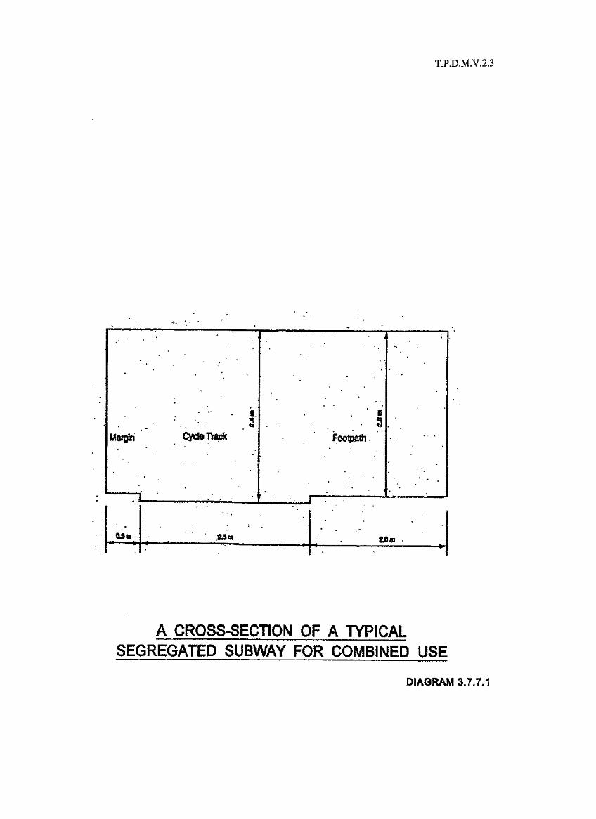
T.P.D.M.V.2.3
Maitfri Cyefe Trade
T L
as*
A CROSS-SECTION OF A TYPICALSEGREGATED SUBWAY FOR COMBINED USE
DIAGRAM 3.7.7.1

T.P.D.M.V.2.3
ffl • 10
(IF) . 1 25 Ism A
• Storing2Sm
;'Cyd«. trade•ootpoth
STOPPING SIGHT DISTANCES FOR CYCLISTS
DIAGRAM 3.7.7.2

T.P.D.M.V.2.3(Al/2001)
Table 3.7.7.2
Design Standards for Footbridges and Subways
Minimum :#effectivewidth
Minimum :#verticalclearance
Ramps :
Stairwavs :
Landings :*
Handrails _•
Footbridges
2m (except on stairs to Tram or similarplatforms where a lesser width is necessarybecause of limited space)
5.1m
Subways
3tn
2.3m (for length less than 23m)2.5m (for length not less than 23m)
Where possible both ramps and stairs should be provided on all approaches.Desirable maximum gradient = 1 in 12
Absolute maximum gradient = 1 in 10
Centre line of circular ramps should never exceed 10%
Stepped ramps should not be provided
Desirable maximum height of risers = 150mm ) Values chosen for
Absolute maximum height of risers = 165mm ) riser height 'R' and(in exceptional circumstances only) ) tread width T
Desirable minimum width of tread = 280mm ) must satisfy both:
Absolute minimum width of tread = 250mm ) 2R+T = 580 to 600 T xR = 42000 to 45000
Desirable maximum flight of steps = 1 2 risers
Absolute maximum flight of steps = 1 6 risers
Ramps steeper than 10% to have landings at vertical intervals not greater than3500mm.
Ramps of 10% or less to have landings at vertical intervals not greater than3500mm where space permits.
Desirable length for stairs = 1500mm - 1800mm
Absolute minimum length for stairs = 1 000mm
Desirable length for ramps = 2000mm
Absolute minimum length for ramps = 1 500mm
Width of all landings = Not less than that of the approachstairs or ramps
Handrails must be provided on both sides of all ramps and stairways, andconsideration should be given to the provision of central handrails on stairways4000mm wide or more.
* Ramps with gradients above 10% require approval from the respective AC for T/Region.
# Adequate allowance should be made for railings/handrails, lightings, finishes, etc incalculating the clear width and height of footbridges/subways.

T.P.D.M.V.2.3(Al/2001)
Table 3.7.7.3
Minimum Dimensions for Segregated and Unsegregated
Subways for Pedestrians and Cyclists
Subway length (m)
Height (m)
Width (m)
Cycle track
Footway
Margin between subway walland cycle track
Cycle track
Footway
Segregated
<23
2.5
2.3
>23
2.7
2.6
0.5
2.5
2.0
Unsegregated
< 23 > 23
2.5 2.7
4.0
Table 3.7.7.4
Stopping Sight Distance for Cyclists
Designed speed
<_10
<25
Minimum stoppingdistance (m)
4.0
26.0
Minimum radius ofcurvature of walls adjacent
to cycle track (m)
4.6
68.0
Minimum radius ofcurvature of walls
adjacent to footway (m)
4.6
28.5

T.P.D.M.V.2.3(Al/2001)
3.7.8 Escalators at Footbridges and Elevated Walkways
3.7.8.1 The criteria for provision of escalators at footbridges and elevated walkways are:
(i) when both stairs and ramps/lifts are provided, escalators should only be considered ifthe estimated number of pedestrians using the footbridge in both directions is at least3,000 pedestrians per hour for at least one hour on a weekday;
(ii) when stairs alone are provided, escalators should be considered where the average ofthe estimated three highest hourly flows in both directions on a typical weekdayexceeds 1,500 pedestrians per hour; and
(iii) both up and down escalators should be provided at footbridges and elevated walkwaysfulfilling these criteria.
3.7.8.2 The above criteria only apply in developed and development area, and should be appliedwith flexibility. Escalators will not normally be considered in other areas. A decision onwhether to include escalators should also take account of other factors such as:
(i) increasing the attractiveness to users of the facility in question in order to discouragepedestrians from crossing roads at-grade, and in particular from jay-walking, therebyreducing the danger of accidents;
(ii) the availability of facilities, e.g. lifts and escalators, in both buildings connected to thefootbridge or elevated walkway; and
(iii) site constraints which inhibit the provision of ramps.
3.7.8.3 The following information on the escalator is useful:
(i) In ascent, escalator have about twice the carrying capacity of steps.
(ii) Escalators should not normally be provided without an alternative means of ascent ordescent, whatever the case may be, as during times of maintenance to the escalatorsthe footbridge will be inoperable.
(iii) Operating capacities range between 112 persons/minute to 150 persons/minute.
(iv) Speeds of escalators range between 0.5m/s to 0.75m/s, 0.6m/s is about 130 personsper metre width per minute.
(v) Escalators in the Territory generally have an angle of inclination of 30 degrees,
(vi) Widths of escalators can vary considerably, depending on the location, aesthetics, andother similar matters. However escalators for footbridges should not generally havean effective width less than 1m if pedestrians are to be allowed to pass one another.
3.7.8.4 For descending escalators, care should be taken that there is sufficient reservoir space at thefoot of the escalator. Preferably descending escalators should not discharge pedestriansonto the footway directly in line with an adjacent carriageway which they then may berequired to cross at grade. Waiting pedestrians can impede the flow of pedestrians beingdischarged from the escalator, or those pedestrians being discharged may because of theirmomentum attempt to cross without paying sufficient attention to approaching vehiculartraffic.

T.P.D.M.V.2.3(Al/2001)
3.8 Cycle Tracks
3.8.1 General
3.8.1.1 The sharing of facilities by cyclists and other road users unless volumes are low is generallynot a satisfactory arrangement because of the interference with the general flow of trafficand the vulnerability of cyclists. Therefore where cycle traffic is relatively large, additionalor segregated facilities for cyclists should be provided.
3.8.1.2 The decision as to whether such facilities should take the form of cycle tracks parallel toexisting or proposed carriageways, or cycle paths entirely separate from other vehicle routeswill be dependent upon, the overall system being planned for, the land that can be madeavailable, and the convenience of the route to cyclists. Inconvenient routes however wellconstructed will not be used by cyclists if there is a more direct route to their destination.
3.8.1.3 When considering the provision of cycle routes interested cycling organisations if possibleshould be consulted so that their opinions on the proposal can be obtained because theirviews as to the usefulness or otherwise of the route will be helpful.
3.8.1.4 The Road Traffic (Traffic Control) Regulations does not prevent, unless appropriate signsindicate otherwise, cyclists from using bus lanes, and it may therefore be appropriate whenplanning cycle routes to take advantage of any bus lanes provided in the area. Howevercaution should be exercised, as the level of flow at which cyclists and buses can mix withoutbuses being impeded or cyclists put at risk is not very high. Contra-flow bus lanes canpresent particular difficulties and danger to cyclists and sharing of these facilities shouldgenerally not be encouraged.
3.8.1.5 Cycle lanes, forming part of the carriageway and exclusively for cyclists, are not specificallyprovided for under the Road Traffic (Traffic Control) Regulations. In any event pastexperience and general traffic conditions would not indicate that such schemes would besuitable at the present time.

T.P.D.M.V.2.3(Al/2001)
3.8.2 Provision of Cycle Tracks
3.8.2.1 The decision to provide separate facilities for cycles will generally be based on accidentrecords and levels of existing or predicted cycle flows. However other arguments notnecessarily having any factual support may also be used to influence the decision on theprovision of cycle facilities. In these latter cases care should be taken that in agreeing tosuch facilities, a reasonable level of cycling activity can be guaranteed and that anoverprovision of facilities is not made. Cycle tracks provided but not used to any extent willquickly deteriorate and may be occupied by undesirable activities. Such under-utilisationcan also prejudice any future provision of cycle facilities.
3.8.2.2 Cycling in the Territory at the present time is mainly recreational, although in the NewTerritories some work journeys are made by cycle. However evidence on such journeys thatare made is sparse and therefore it is difficult to provide warrants for cycle tracks based onlocal experience and reliance has to be put on information published abroad, which may ormay not be entirely relevant to local conditions.
3.8.2.3 Table 3.8.2.1 gives guidelines as to when to provide cycle facilities based on informationfrom abroad Recommended Practice for the Design and Layout of Cycle tracks. However itis suggested that these figures be used with caution, as given the very dense trafficconditions in urban areas in the Territory it is quite likely on safety grounds that segregatedfacilities for cyclists could be justified for much lower flows.
Table 3.8.2.1
Guidelines for the Provision of Cycle Facilities
Rural Areas Urban Areas Facility
Cycle flows per 750 1000 Inside lane of carriageway widened to16hrday 4.5m
1000 1500 Provide separate cycle track

T.P.D.M.V.2.3(Al/2001)
3,8.3 Design of Cycle Tracks
3.8.3.1 Table 3.8.3.1 shows appropriate minimum widths to be used for cycle tracks.
Table 3.8.3.1
Cycle Track Widths
Desirable (m) Minimum (m)
One way 2.8 2
Two way 4.0 3.5
3.8.3.2 Whilst 2m should be regarded normally as the minimum width for a one way cycle track, inother countries much narrower tracks have been used. Therefore in considering whether acycle track should be provided or not, it may be preferable to provide a substandard widththan none at all. Normally such widths should not be less than 1.5m for a one way track aseven with this overtaking may be difficult and lead to encroachment onto adjacent footwaysor verges.
3.8.3.3 Figures on capacities for cycle tracks vary considerably, however a reasonable guide formost situations would be 500 cycles per metre width per hour for one way operations and400 cycles per metre width per hour for two way operations.
3.8.3.4 Cycle tracks should be separated from any adjacent carriageway by a verge of at least 1.8min width. In difficult situations, other than for Trunk Roads this width may be reduced tonot less than 1m to allow reasonable clearances from any street furniture.
3.8.3.5 Gradients for cycle tracks will generally be dictated by the surrounding topography,however wherever possible these should not be excessive as this may distract from cyclistsusing the route.
3.8.3.6 Long gradients over 5% will cause cyclists to dismount, and therefore as a general guide,maximum gradients of 3% to 4% should be the aim. Where the cycle track follows the maincarriageway route, the gradient will be dictated by this and no special attempt should bemade to provide lesser gradients, however where excessive long gradients could resultconsideration should be given as to the actual usefulness of providing the cycle track orwhether a more convenient route might be available elsewhere.
3.8.3.7 At subways and footbridges the desirable and normal maximum gradients are 4% and 8%respectively. In exceptional circumstances gradients of up to 10% may be acceptable withthe approval of the respective AC for T/Region. For combined cycle/pedestrian ramps, theflatter ramps will often not be appropriate because of the greater pedestrian walkingdistances involved. Consideration should always be given to requiring cyclists to dismountat subways and bridges, particularly those which are shared with pedestrians.
3.8.3.8 Horizontal radii should preferably be not less than 5m, but in difficult conditions radii of 2mmay be acceptable. Sharp reverse curves should be avoided.
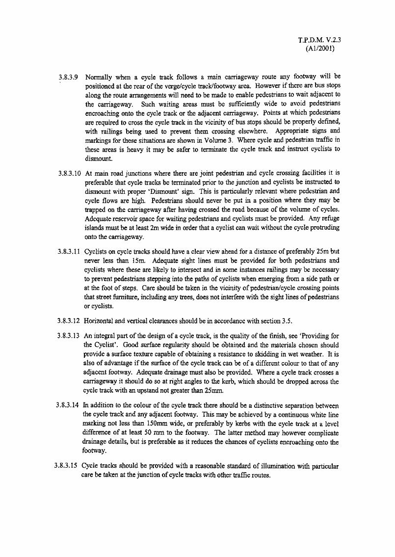
T.P.D.M. V.2.3(Al/2001)
3.8.3.9 Normally when a cycle track follows a main carriageway route any footway will bepositioned at the rear of the verge/cycle track/footway area. However if there are bus stopsalong the route arrangements will need to be made to enable pedestrians to wait adjacent tothe carriageway. Such waiting areas must be sufficiently wide to avoid pedestriansencroaching onto the cycle track or the adjacent carriageway. Points at which pedestriansare required to cross the cycle track in the vicinity of bus stops should be properly defined,with railings being used to prevent them crossing elsewhere. Appropriate signs andmarkings for these situations are shown in Volume 3. Where cycle and pedestrian traffic inthese areas is heavy it may be safer to terminate the cycle track and instruct cyclists todismount.
3.8.3.10 At main road junctions where there are joint pedestrian and cycle crossing facilities it ispreferable that cycle tracks be terminated prior to the junction and cyclists be instructed todismount with proper 'Dismount5 sign. This is particularly relevant where pedestrian andcycle flows are high. Pedestrians should never be put in a position where they may betrapped on the carriageway after having crossed the road because of the volume of cycles.Adequate reservoir space for waiting pedestrians and cyclists must be provided. Any refugeislands must be at least 2m wide in order that a cyclist can wait without the cycle protrudingonto the carriageway.
3.8.3.11 Cyclists on cycle tracks should have a clear view ahead for a distance of preferably 25m butnever less than 15m. Adequate sight lines must be provided for both pedestrians andcyclists where these are likely to intersect and in some instances railings may be necessaryto prevent pedestrians stepping into the paths of cyclists when emerging from a side path orat the foot of steps. Care should be taken in the vicinity of pedestrian/cycle crossing pointsthat street furniture, including any trees, does not interfere with the sight lines of pedestriansor cyclists.
3.8.3.12 Horizontal and vertical clearances should be in accordance with section 3.5.
3.8.3.13 An integral part of the design of a cycle track, is the quality of the finish, see 'Providing forthe Cyclist'. Good surface regularity should be obtained and the materials chosen shouldprovide a surface texture capable of obtaining a resistance to skidding in wet weather. It isalso of advantage if the surface of the cycle track can be of a different colour to that of anyadjacent footway. Adequate drainage must also be provided. Where a cycle track crosses acarriageway it should do so at right angles to the kerb, which should be dropped across thecycle track with an upstand not greater than 25mm.
3.8.3.14 In addition to the colour of the cycle track there should be a distinctive separation betweenthe cycle track and any adjacent footway. This may be achieved by a continuous white linemarking not less than 150mm wide, or preferably by kerbs with the cycle track at a leveldifference of at least 50 mm to the footway. The latter method may however complicatedrainage details, but is preferable as it reduces the chances of cyclists encroaching onto thefootway.
3.8.3.15 Cycle tracks should be provided with a reasonable standard of illumination with particularcare be taken at the junction of cycle tracks with other traffic routes.

T.P.D.M. V.2.3(Al/2001)
3,8.4 Signs and Markings for Cycle Tracks
3.8.4.1 Appropriate traffic signs and markings for cycle tracks are shown in Volume 3.
3.8.4.2 To encourage the use of cycle routes, adequate direction signing should be provided, and inthis respect it may be necessary to incorporate in main road signing the direction to cycleroutes where this is not obvious. At the start of a cycle route, signs should indicate majordestinations along and at the termination of the route. At intersections of routes, appropriatedirection signing should also be provided. Where a cycle track is parallel to the carriagewayadditional direction signing would not normally be necessary as the main road signs shouldbe sufficient for this purpose.

T.P.D.M. V.2.3(Al/2001)
3.9 Railings, Barrier Fences and Crash Cushions
3.9.1 General
3.9.1.1 The provision of a particular barrier fence along a road depends on many factors such aspedestrian and traffic flow, road geometry, historic accident data, surrounding environmentand sometimes, consideration has to be given on aesthetic side. The Transport Department,Fire Services Department, Hong Kong Police Force, Highways Department and otherconcerned parties as appropriate should be consulted before a barrier fence is to be erectedor replaced on public roads.
3.9.1.2 Reference should be made to the Highways Department Standard Drawings for the detailedinformation of barrier fences and railings that are commonly used on public roads. As forvehicular parapets and pedestrian parapets on highway structures, Structures Design Manualfor Highways and Railways should be referred..

T.P.D.M. V.2.3(Al/2001)
3.9.2 Railings
3.9.2.1 Railings are generally used for the control, protection and guidance of pedestrians alongfootways or footpaths, but may also be used in certain circumstance to prevent parking.
3.9.2.2 Railings to prevent pedestrians injuring themselves should always be provided where thelevel difference between the footway and adjacent carriageway verge or other area is greaterthan 1500 mm or there is a steep downhill slope at the back of the footway.
3.9.2.3 Railings should be provided to prevent pedestrians spilling onto the carriageway oppositeexits to cinemas, theatres, schools, or to other places where similar sudden large pedestrianflows might be expected. In particular, at school exits, railings should be provided andextended to a safe crossing or roadside pick-up point. Further, if large flow of smallchildren is anticipated, special railings providing increased visibility is desirable.
3.9.2.4 When pedestrian flows are in the vicinity of or exceed the capacity flows given in Table3.4.11.1, railings should generally be erected to prevent pedestrians from walking onto thecarriageway. However, where these conditions occur on footways less than 2 m in widthdiscretion will be necessary, as the installation of railings might make conditions worsebecause of the reduction of effective footway width.
3.9.2.5 In the immediate vicinity and on either side of at-grade crossing points railings should beerected to channel pedestrians to the crossing points and to reduce jay walking. The exactlength of the railings required will depend upon individual site conditions, but normally thelengths of railing should desirably be 15 m or if not possible, at least 6 m on either side, butsee also paragraph 3.9.2.9.
3.9.2.6 In the vicinity of grade-separated crossings, generally railings will need be erected along thefootway for considerably longer lengths than for at-grade crossings, to encourage the use ofsuch facilities. Exact length of railing will depend upon circumstances prevailing, but theminimum sufficient railing in the vicinity of the entrance/exit will be needed to preventpedestrians from encroaching onto the carriageway.
3.9.2.7 For dual carriageway along District or Local Distributor Roads, railings should be erectedalong the central reservation to prevent pedestrians from crossing the roads other than atdesignated crossing points.
3.9.2.8 In respect of the above paragraphs it is relevant to note that Regulation 39 of the RoadTraffic (Traffic Control) Regulations prohibits pedestrians from:
(i) Crossing within a zebra controlled area other than on a zebra crossing.
(ii) Crossing within 15m of a light signal crossing otherwise than at the crossing wheresuch lights operate.
(iii) Crossing within 15m of a footbridge or subway or any part of it otherwise than bymeans of the footbridge or subway,
(iv) Climbing over or through any kerbside fence or central reservation onto acarriageway.
The careful use and choice of railing type will assist in the enforcement of this regulation,though it may not always be possible to extend railings over the full length affected, becauseof servicing requirements or other reasons.

T.P.D.M. V.2.3(Al/2001)
3.9.2.9 Railings will be required to contain and channel pedestrians on traffic islands wherestaggered crossings are installed. There should be sufficient room on the island forpedestrians to wait on the island.
3.9.2.10 If indiscriminate crossing of the carriageway is a factor in frequent pedestrian accidents,consideration may be given to installing railings along complete sections of streets.However, where this is contemplated, consideration must be given to the servicing offrontage developments.
3.9.2.11 Where illegal parking of vehicles on footways is a particular problem but control ofpedestrian movements is not, tubular amenity railings may be installed. The gap betweenlengths of railings may be varied according to prevailing circumstances and may be as muchas 2.5 m for footways whose width is not greater than 2 m, or 2 m where the footway isgreater than 2 m in width. The wider gaps should be employed where servicing of frontagedevelopments or the setting down or picking up of passengers is frequent. Low heightconcrete or steel bollards are an alterative means of preventing parking on footways, butthese generally do occupy more footway space and may create an unnecessary hazard topedestrians with disabilities, particularly those with visual impairment. However concreteor similar bollards can aesthetically be more acceptable particularly in prestigious areas, orareas where pedestrians do not have access.
3.9.2.12 Typical railing types including tubular railings and Type 2 railings are shown in Diagrams3.9.2.1 and 3.9.2.2 whereas pedestrian parapets on pedestrian footbridges and subways areshown in the Structure Design Manual for Highways and Railways. Any other suitablydesigned railing types used should be approved by Highways Department.
3.9.2.13 At crossing points or similar locations, it will be necessary to modify the Type 2 railings asshown in the Highways Department Standard Drawings in order that the visibility ofmotorists is not impaired. For similar reason, banners should be prohibited from hanging oneach side of the crossing point for a length of about 30 m.
3.9.2.14 In prestige areas dwarf walls may be used instead of railings and these are particularlyapplicable where planting of verges and central reservations on District or Local DistributorRoads is considered appropriate.
3.9.2.15 Railings or dwarf walls should not be used in the vicinity of carriageways of Trunk Roads orPrimary Distributors for which barrier fences should be used.
3.9.2.16 Horizontal clearances of railings from the edge of carriageway should generally be inaccordance with Table 3.5.2.1 but in circumstances where this would reduce effectivefootway width to below 1.5 m the minimum clearance may be reduced to 200 mm.

T.P.D.M.V.2.3(A1/2001 )
i
if••"
8
S. ••! .
.1 • •
' i±w.
1
fi>
-
"
A
i.
' *\
• A
i
1
1t
\
1<
11
I
I
\
....•;*
• a, -*f >" «. < ' .1
I .
I• • i
. .-. 1
>• = ' s 1:; :,.:(Tj: * •
%
~ it
* I
• A * J
* ..I
J. '«..•'.
rin
= , . .
.^
1
i«tse
w
-
M
CONCfi£TEJ —
W
« •"*
. » £
-
• •- - ';>i -
* •* »
JYf*lCAL DETAILS OF TYPE
•
TYPE-
• ' :.-
* .
• A
.2 RAJ ws
r
* !i- •!•
- i
• fr* * I: ».H
-
4 .
' 4 '
a
77//
'- . .
: - ' , . - •' ! •
.,•
• *
• 7r *1
-•—•—*•- £(J|jCRETE
«
• A
* Oh
r .iti?
T.P.D.M. V.2.3(Al/2001)
3.9.3 Barrier Fences
3.9.3.1 Safety barrier fences and vehicular parapets are intended to prevent vehicles leaving thecarriageway and keep any damages and injuries to the vehicles and their occupants to aminimum. The approved types for use in the Territory are untensioned corrugated beambarrier fences, concrete profile barrier fences and vehicular parapets. Apart from vehicularparapets which are shown in Structures Design Manual for Highways and Railways, theapproved barrier fences are shown in Diagram 3.9.3.1 and for further details, refer toHighways Department Standard Drawings.
3.9.3.2 Barrier fences will generally only be used on Trunk Roads, Primary Distributors and RuralRoads in circumstances when it is considered that more danger will be occasioned to thevehicle and its occupants in leaving the carriageway than if it is constrained by barrierfences. To accomplish this goal, the barrier fences need to be long enough to shield thehazard, be strong enough to contain the vehicle, and be designed to allow for smoothredirection of vehicle with tolerable deceleration. Where both barrier fences and railings areprovided alongside with each other, the clearance between them should not exceed 250 mmto prevent children passing through the gap.
3.9.3.3 It is important that the required horizontal clearances as set down in Table 3.5.2.1 areachieved. In cases where a hard shoulder or marginal strip in accordance with sections3.4.7, 3.4.9 and 3.4.12 is provided this will generally be automatically achieved, butelsewhere the barrier fences may have to be set back. Where concrete profile barriersreplace existing fences, or central reservation railings, the minimum clearance between thefoot of the barriers and the edge of carriageway may be reduced to 300mrn. Where thisreduced clearance is adopted, care should be taken that the clearance to other street furnituresuch as lighting columns, gantry legs, traffic signs etc. does conform to Table 3.5.2.1.
3.9.3.4 It should be noted that concrete profile barrier fences should never be installed without anaccompanying marginal strip constructed to the same standard as the carriageway andincorporating a continuous edge line marking in accordance with Volume 3. Normally themarginal strip will be formed from the available verge or central reserve width, but wherethis cannot be achieved the carriageway itself should be used and the lane widths reducedaccordingly. The edge line marking is important in clearly defining the edge of carriagewayparticularly at night as concrete profile barriers are not always clearly discernible. Themarginal strip provides the necessary minimum clearance from the carriageway and givesthe motorists a further chance of avoiding the barrier should he momentarily lose control.
3.9.3.5 Terminal sections including those at emergency crossings must be ramped down or providecrash cushions as appropriate to avoid more serious injury occurring to occupants ofimpacting vehicles. Details of the ramp down are given in the Highways DepartmentStandard Drawings.
Untensioned Corrugated Beam
3.9.3.6 There are two types of untensioned corrugated beam safety fences, i.e. with compacted earthfootings and with concrete footings.
3.9.3.7 The safety fences with compacted earth footings are less rigid than those with concretefootings. They need considerable deflection space and are generally suitable only for widecentral reservations.

350
100
W-BEAU
T.P.D.M. V.2.3(Al/2001)
CROSS SECTION
CONCRETE PROFILE BARRIER FENCE
308 508
-I- LtTf
I«
>X
STANDARD THRIBEAM
UNTENSIDNED BEAM BARRIER
MODIFIED THRIEBEAM
TYPICAL BARRIER FENCESNOTE: ALL DIMENSIONS ARE IN MILLIMETRES.
DIAGRAM 3.9.3.1

T.PD.M. V.2.3(Al/2001)
3.9.3.8 The other safety fence type with concrete footings, which should be fixed to concrete anchorblocks, can be used at locations where structures need to be protected and there is limiteddeflection space. The untensioned corrugated beam safety fence stated in the followingparagraphs refers to the concrete footing type unless otherwise specified.
3.9.3.9 Posts of these safety fence types should normally be at 4 in spacing. However, the spacingshould be reduced to 2 m if greater rigidity is required for protection of lighting columns andstructures or where traffic accident black spot site is located.
3.9.3.10 The corrugated beam safety fence installed for the protection of lighting columns andstructures should
(i) have posts spaced at 2 m;
(ii) have sufficient clearance as suggested in Table 3.9.3.1 between the back of the postand the face of the structure being protected; and
(iii) extend at full height at least 10 m in advance of the structure and at least 6 m beyondit. For further details on design length of safety fence, refer to paragraph 3.9.3.32.
3.9.3.11 The beam should be 'blocked out' for a minimum of 200 mm from the support post toenable an impinging vehicle to slide smoothly along the beam without being entrapped bythe post and also helps to maintain the height of the beam when the posts are bent back onimpact, thus preventing the vehicle from rolling over.
3.9.3.12 Where space is limited and blocking out pieces cannot be used, the beam may be attacheddirectly to the post. Other alternatives such as road widening, reduction of speed limit anderection of appropriate warning sign should also be considered.
3.9.3.13 Safety fences are generally accepted to be more effective when kerbs are not present.However, if corrugated beam fence is installed intermittently only to protect structuralcolumns or similar on roads other than Trunk Roads, kerbs may be provided with the safetyfence positioned behind them.
3.9.3.14 The safety fence must be erected with its centre line at a height of 600 mm measured from:
(i) the surface of the adjoining carriageway, margin strip or hard shoulder if this is within1500 mm of the beam; and
(ii) the surface of the ground below the beam if the beam is more than 1500 mm from theadjoining carriageway, margin strip or hard shoulder.
3.9.3.15 Beam sections should be lapped in the direction of traffic flow and its ends should beramped down and flared away from the carriageway.
3.9.3.16 The traffic face of safety fence should be in line with and preferably connected to any bridgeparapet with which it is contiguous.
Thriebeam
3.9.3.17 The standard thriebeam is similar to the untensioned corrugated beam but has three numberof troughs (or crests) instead of two and is mounted higher. This is much stiffer than theconventional corrugated beam due to its stronger posts, beam rail and closer spacing ofposts.

T.P.D.M. V.2.3(Al/2001)
3.9.3.18 The standard thriebeam can reduce the incidence of rolling over in large vehicle collisionsmore effectively. This is accomplished by increasing the beam mounting height to 875 mmand using a stronger blockout. It is therefore preferable to the untensioned corrugated beamwhen there is high frequency of traffic accidents involving vehicles of high centre of gravity.
3.9.3.19 In the event that the standard thriebeam is deemed not sufficient because frequent impact byheavy vehicles is expected, the standard blockout for thriebeam shall be replaced by a 350mm deep modified blockout. Such blockout has a notch at the bottom.which allows thelower portion of the beam and the flange of the spacer block to bend in during collision byvehicles of high centre of gravity, keeping the rail face nearly vertical and thereby retainingthe vehicle from rolling over.
3.9.3.20 The use of standard/modified thriebeam can be considered where a higher rigidity of barrierfence than corrugated beam is required but concrete profile barrier is not warranted due tothe associated cost, accident risk and space availability, etc. This type of barrier can moreeffectively reduce the incidence of rolling over by high vehicles when impacted. Thethriebeam barriers should be installed at the following locations:
(i) On roads with a speed limit of 70 km/h or above, on the outside curve of the bend ofradius R4 or below and on top of the downhill slope;
(ii) On roads with a speed limit of 50 km/h, on R3 or below road bends adjacent todownhill slope.
Concrete Profile Barrier
3.9.3.21 The theory of the concrete profile barrier is that when a vehicle strikes at an angle of 15° orless the impact energy is absorbed in compressing the suspension of the vehicle. The frontwheels of the vehicle climb up the 55° slope and on contact with the upper slope the wheelsare turned parallel to the barrier's longitudinal axis and the vehicle is redirected.
3.9.3.22 The concrete barrier will contain most vehicles within the carriageway, though at highangle, serious damage can result.
3.9.3.23 Concrete profile barriers require little maintenance, therefore they are ideal for locationswhere maintenance would cause considerable traffic disruption. However, because of thedamage that can be caused to vehicles and their occupants by high angle impacts, thepotential risk of this type of accident occurring, particularly on roads having a design speedor speed limit of 80 km/h or more, should also be taken into account when considering theuse of this type of barrier fence.
3.9.3.24 Although the concrete profile barrier requires minimum space, it can have an inhibitingeffect on motorists and therefore a parallel hard strip should always be provided between thebarrier and the edge of the carriageway. Where the hard strip is 1500 mm or more the hardstrip should be delineated by 200 mm wide continuous white line, where it is less than 1500mm wide the hard strip should be 100 mm wide continuous white line. The hard stripshould never be less than 300 mm wide, and preferably should be wider.
3.9.3.25 While planting is aesthetically pleasing on central reservations, care should be taken,particularly when used in conjunction with concrete profile barriers that sight lines are notobscured either at the time of planting or by subsequent growth.

T.P.D.M. V.2.3(Al/2001)
3.9.3.26 A ramp down concrete end treatment is used to terminate a concrete profile barrier inlocations where speed limit is 50 km/h or less and space is limited. For speed limit greaterthan this, flare end treatment or crash cushion may be considered.
Criteria for the Provision of Safety Barrier Fences
3.9.3.27 The following criteria should be taken into account when considering the provision of safetybarrier fences:
(i) Barrier fences should always be provided to protect the supports of overbridges,gantries or other structures that might collapse with catastrophic effects if struck byan errant vehicle. However, lighting columns on roads with a design speed or speedlimit of 50 km/h or less, and traffic signs on single posts are not included in thiscategory.
(ii) Barrier fences should normally be provided on dual carriageway roads with a speedlimit or design speed of 70 km/h or greater where:
(a) the road is on an embankment which is 3 m or more in height; or
(b) the road is on a retaining wall which is 2 m or more in height; or
(c) the central reservation is less than 3 m in width; or
(d) the road is adjacent to another road, a railway or a permanent body of watermore than 0.5 m deep.
(iii) Barrier fences may be provided on single carriageway roads with a speed limit ordesign speed greater than 50 km/h and dual carriageway roads with a speed limit ordesign speed less than 70 km/h where:
(a) the horizontal radius is at or less than the minimum radii for 10%superelevation given in Table 3.3.3.1 of this Chapter; or
(b) the road is on an embankment or a retaining wall which is greater than 1.5 m inheight; or
(c) the central reservation is less than 3 in wide; or
(d) the road is adjacent to another road, a railway or a permanent body of watermore than 0.5 m deep.
(e) Barrier fences should not normally be provided on single carriageway roadswith a speed limit or design speed of 50 km/h unless hazardous circumstancesprevail such as steep slope or retaining wall adjacent to the road, or sharp bend.
3.9.3.28 Barrier fences should not be placed behind kerbs or on side slopes steeper than 1:6 to avoiderrant vehicles mounting the barrier fences and thereby affecting the performance of thebarrier fences.

T.P.D.M. V.2.3(Al/2001)
3.9.3.29 A distance of at least 1000 mm from the traffic face of safety fence or 600 mm from theback of post whichever is greater should be provided for any corrugated beam barrier fenceserected adjacent to the edge of a downhill slope or a retaining wall to allow the dynamicdeflection of the fences during the impact. It is stressed that if kerbs are present, it isdesirable to set the barrier face in the same line as the kerbline. Otherwise, additionaldynamic deflection should be allowed.
3.9.3.30 For an uphill slope, the height and slope angle are the factors determining whether barriershould be provided in front of the slope. In the comparison of the severity of vehicularimpacts with slope to that with safety fences, Roadside Design Guide suggested that safetyfences should be provided for less severity when the slope angle is greater than 20° and theslope height is greater than 3 m.
3.9.3.31 If no barrier fence is provided in front of an uphill slope, attention should be given to ensurethat the slope surface within a height of 1000 mm from the adjacent pavement should besmooth.
3.9.3.32 Dynamic deflection varies according to the impact speed, impact angle and thecharacteristics of the barrier fences. For an impact angle between 20° and 25°, Table 3.9.3.1gives the minimum distance to the hazard.
Table 3.9.3.1
Dynamic Deflection for Various Barrier Types and Speeds
Barrier type/Speed
W-beam barrier with postsspaced at 2 m centres
Standard/ModifiedThriebeam barrier withposts spaced at 2 m centres
Distance between back of post and obstacle
80km/h
1.2m
0.5m
90km/h
1.3m
0.7m
lOOkm/h
1.4m
0.9m
HOkm/h
1.6m
l . lm
3.9.3.33 The effective safety fences should be extended far enough upstream and downstream toprevent errant vehicles from hitting the hazardous object.
3.9.3.34 The safety fence may be flared so that they are installed away from the kerbline as itapproaches its terminal. The flaring of safety fence has several purposes as follows:
(i) The total length of safety fences can be reduced.
(ii) The safety fences can be located further away from the travel lanes.
3.9.3.35 The disadvantage of flared fences is that the greater the flare rate, the higher the angle atwhich an errant vehicle can hit. Also, greater flare rate will increase the possibility of animpacting vehicle being redirected back into or across the carriageway following an impact.This situation is especially undesirable on two way carriageway where the impact vehiclecould be redirected into on-coming traffic.

T.P.D.M. V.2.3(Al/2001)
3.9.3.36 The detailed design for the required length of safety fence to shield the hazard can bereferred to Roadside Design Guide and Road Design Guide.
3.9.3.37 As a rough guide based on the recommendations from the above references, Table 3.9.3.2shows the suggested flare rates for safety fence.
Table 3.9.3.2
Suggested Flare Rates (1 :x) for Safety Fence
Speed Limit
110
100
90
80
70
60
50
Flare rate for safety fence beyond shy line
Weak post system withcompacted earth footing
15
15
12
11
10
10
10
Strong post systemwith concrete footing
20
20
16
15
12
10
10
Flare rate for safetyfence inside shy line
30
30
25
21
18
16
15
Clearance between Barrier Fences and Carriageway
3.9.3.38 The horizontal clearance of barrier fences from carriageway should follow the requirementsset out in Section 3.5.2 of this chapter.
3.9.3.39 Concrete profile barrier should not be set back more than 3500 mm from the edge of thecarriageway to reduce the severity of impacts occurring at high angles.
Parapet
3.9.3.40 A parapet is a structural component installed along the edge of a bridge or similar structureintended to prevent vehicles or pedestrians from falling off. For types, details and uses ofparapets, refer to Chapter 15 of the Structures Design Manual for Highways and Railways.

T.P.D.M. V.2.3(Al/2001)
3.9.4 Crash Cushions
3.9.4.1 Where fixed objects cannot be removed, relocated or shielded by longitudinal barrier,crash cushions may be provided to slow down a vehicle to a safe stop for head-on impactsor redirect a vehicle away from the fixed object for side impacts so that the potential forserious injury to its occupants is eliminated.
3.9.4.2 Most crash cushions perform their functions by the principle of kinetic energy absorption ormomentum transfer. Some crash cushions use a combination of these principles.
3.9.4.3 Different types of crash cushions possess different functions. The crash cushion type whichsuits Hong Kong most shall be able to withstand head-on, side-angle and reverse-angleimpacts up to the design speed that the crash cushion can withstand. The design speed shallbe taken to be the posted speed limit plus additional safety margin speed of 10 km/h to takeinto account the possible speeding of a vehicle. Furthermore, the crash cushion shall be ableto perform the following characteristics:
(i) The crash cushion shall not allow the impacting vehicle to pass through the attenuatorwhen it is struck at an angle on the front or "nose" to avoid the potential for secondaryimpacts.
(ii) It shall redirect vehicle in all designed side impacts on the unit at angles notexceeding 20° back to the originally travelled direction at no greater than 60% of theimpact angle to avoid the potential for secondary accidents with vehicle travelling inadjacent travel lane.
(iii) The crash cushion shall be designed to be free from any protruding elements that maycause an errant vehicle to change direction in an uncontrolled phenomenon that willincrease the potential for secondary accidents.
(iv) It shall also possess anti-climb characteristics to ensure that impacting vehicle will notroll over the system.
3.9.4.4 To ensure a crash cushion type satisfies the above required characteristics, it shall meet theevaluation criteria of National Cooperative Highway Research Program (NCHRP) Report350 of U.S.A. for different test levels 1 (50 km/h), 2 (70km/h) and 3 (100 km/h). The crashcushion must be compliant with three dynamic performance evaluation criteria that arestructural adequacy, occupant risk and post-impact vehicular trajectory.
3.9.4.5 The crash cushion so chosen should be wide enough to shield the ends of median barriers orother hazardous objects.
3.9.4.6 A transition section is needed between the back of the system and the barrier when the crashcushion cannot be attached directly to a median barrier or there exists a gap of greater thanor equal to 500 mm wide between them. Such transition section should also be provided ifthe median barrier terminates in sloping end.
3.9.4.7 The road surface on which the crash cushion is installed must be free from kerbs. Thepath between the carriageway and the crash cushion should be clear of any obstruction orirregularities. In addition, for structures, they should be placed free of joints.
3.9.4.8 Retroreflective sheeting should be provided on the nosing of the crash cushion barrier tomake it more conspicuous at night and during inclement weather.
T.PD.M. V.2.3(Al/2001)
3.9.4.9 Since the crash cushion barriers are proprietary products, the dimensions corresponding toany particular design speed that they are designed to cater for are varied for differentproducts. It is therefore desirable to obtain the dimensions of those crash cushion barriersavailable in the market. For new highway design, the largest size of the available productin the market in respect of the design speed should be adopted. Further, the necessarychevron road markings should be so designed to allow for the proposed crash cushionbarrier to be installed with sufficient horizontal clearance as specified in Table 3.5.2.1.
3.9.4.10 Crash cushions are desirable to be provided under the following criteria:
(i) For high speed road with a speed limit of 70 km/h or above;
(ii) In front of the terminal of barriers where the diverging point for main roads and sliproad are located; and
(iii) The main road and slip road are grade separated or at a level difference betweenthem.
3.9.4.11 For any traffic black spot locations with potential hazards, such as bridge column, notcomplying with the above criteria, the necessity of the crash cushion barrier installationshould be studied on an individual basis.

T.P.D.M. V.2.3(Al/2001)
3.10 Road Tunnels
3.10.1 Geometric Design Standards
3.10.1.1 It is important that the geometric design standards in Tunnels should take into account thoseused on the approach roads, and as far as possible no discontinuity in the route occurs, andthe capacity in the tunnel is the same as on the approach road. Each case will however needto be considered on its own merit, according to economic and other relevant factors.

T.P.D.M. V.2.3(Al/2001)
3.10.2 Road Cross Section in Tunnels
3.10.2.1 Whilst it may be economic to reduce the carriageway width, it should be remembered thatthe effective carriageway width in a tunnel is in fact generally less than on the approachroads because of the double white line system used for lane control. A further reduction ofeffective width may also be induced because of the effects of "kerb shyness", though thismay be difficult to determine.
3.10.2.2 To counter act the effects, of "kerb shyness" and the double white line system, for roadsafety reasons it is recommended that a 500 mm marginal strip be provided on both sides ofthe carriageway in each tube.
3.10.2.3 It is essential that a walkway be provided on both sides of the carriageway to enablemaintenance to take place, allow access to emergency telephone equipment, and, providesufficient width for doors of emergency equipment to be opened without encroaching ontothe carriageway. Past experience has found that raised walkways are preferable for safetyreasons and the minimum height of walkway above the carriageway is recommended to be500 mm. The maximum height of the walkway should not exceed 650 mm unless staircasescan be provided from the carriageway to allow drivers from broken down vehicles to gainaccess to the emergency equipment. It is also recommended that the walkway including theside or vertical face should be constructed of material that is of a different and contrastingcolour to the carriageway surface.
3.10.2.4 Carriageway and walkway dimensions are summarised in Table 3.10.2.1.
Table 3.10.2.1Summary of Carriageway and Walkway Dimensions in Tunnels
Single Tube Tunnel
Carriageway width
2-lane
3-lane
44ane(2)
Marginal Strip
Walkway width
Height of Walkways
Desirable
(m)
7.3
0.5
1
0.65 (3)
Minimum
7.3
0.5
0.8
0.5
Dual Tube Tunnel Dimensions foreach one way single carriageway tube
Desirable
(m)
7.3
11
14.6
0.5
1
0.65 (3)
Minimum
(m)
6.75
10(1) (for speed limit of50 km/h only)
13.5
0.5
0.8
0.5(1) A 10m wide dual 34ane carriageway can only be adopted on a very special case and
prior approval from TD is required.(2) It is undesirable to use a 4-lane carriageway for economic reason(3) If staircases from the carriageway are provided at regular intervals this may be
increased.

T.PD.M. V.2.3(Al/2001)
3.10.2.5 Both vertical and horizontal clearances should conform to those given in Tables 3.5.1.1 and3.5.2.1 respectively. In respect of vertical clearances, overhead traffic signals, signs,lighting units or similar must not project below the minimum vertical clearance. Thevertical clearance is provided between the ceiling and the structure gauge for the installationof traffic aids and surveillance equipment.
3.10.2.6 Diagram 3.10.2.1 shows a typical cross section for two tunnel types.
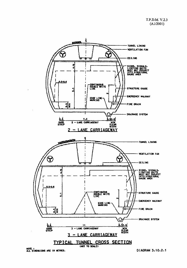
T.P.D.M. V.2.3(Al/2001)
TUNNEL iimmVENTILATION FAH
SIGHS. SIGNALS,LIGHTING UNITSwysT mr PROJECTINTO STRUCTURALSAiffcE AREA
STRUCTURE SAUCE
OCRGOCY WALKWAY
FlfiE DflAlii
$T$TEH
n&mSTRIP
2 «CLEAR¥10TH
STRIP3 - LAME CARRIAGEWAY UIH
CLEAR8IDTH
3 - LANE CARRIAGEWAY
TYPjCAi, TUNNEL CROSS SECTION
ARE IN METRES.
¥EMT!LATiOif FAB
CEILING
SIGHS* SIGNALS*LIGHTING ONiTSHJST NOT PROJECTINTO STHUCTWAi
AREA
STWJCTUftE GAUGE
EICRGEICY MUC1AY
F1HE DRAIN
DRAIMAGE SYSTEM
(MOT TO SCALE!
DIAGRAM 3,10.2.1

T.P.D.M. V.2.3(Al/2001)
3.10.3 Signing and Signalling for Tunnels
3.10.3.1 The signing and signalling for Tunnels should conform to Volume 3.
3.10.4 Lighting for Tunnels
3.10.4.1 More lighting should be provided at the entrance of tunnel than is usually provided within,to enable motorists in the daytime to adapt more quickly to the darker environment inside itfrom the relatively bright environment outside. It is particular important from road safetypoint of view.

T.P.D.M. V.2.3(Al/2001)
3.11 Single Track Access Roads
3.11.1 Introduction
3.11.1.1 In many rural and urban fringe areas there are small isolated developments which will onlygenerate low vehicular and pedestrian flows and to which it would be both difficult andexpensive to construct normal two lane roads. In such cases a single track access road withpassing bays may be adequate.
3.11.1.2 Many single track access roads have already been constructed, both legally and illegally, andwhere properly planned have been found to operate efficiently. The main reasons for asingle track road not working efficiently are:
(i) Inadequate provision of passing bays which are not intervisible.
(ii) Inadequate provision of parking spaces resulting in passing bays, footpaths, verges oreven the road being used for illegal parking.
(iii) Excessive or unsuitable land uses resulting in high traffic flows,
(iv) Motorists driving too fast.
(v) Road works or other construction works requiring partial/complete closure of theroad.
3.11.1.3 This section sets out guidelines for the planning and design of single track access roads.Where a desirable minimum is given, this is normally the absolute minimum for a designspeed of 50km/h, whereas the absolute minimum quoted is that for a design speed of30km/h.
3.11.1.4 It should be noted that some of these traffic engineering standards are lower than for normalroads. However, within the constraints imposed when upgrading existing tracks, it isappreciated that difficulty may still occur in fully achieving the new standard. The designershould consider together with the Traffic Engineer the relevant implications and agreewhether a lower standard improvement is acceptable.
T.P.D.M. V.2.3(Al/2001)
3,11,2 Use
3.11.2.1 Whenever a single track road is being considered the appropriate Regional Office ofTransport Department should be consulted at an early stage to obtain their approval inprinciple.
3.11.2.2 Single track roads with passing places maybe provided where traffic flows will be light andwhere there is, or will be, little or no kerbside activity. Their use will therefore be mostappropriate as access roads to isolated rural villages, urban fringe areas, minor recreationalareas, or similar facilities with low trip generation.
3.11.2.3 Where any new road is constructed it will be likely to generate additional traffic and openup an area for further development. Both factors must be carefully considered whendeciding whether a single track road would be adequate to serve an area.
3.11.3 Design Flows
3.11.3.1 Whilst it has been found that a single track road when provided with adequate passingplaces can accommodate 2-way flows of 100 vehicles per hour, this should not be used as adesign figure. This flow would only be acceptable as an isolated peak flow but not a regulardaily occurrence. The normal daily 2-way traffic flow should not exceed 500 vehicles perday. The effect of long vehicles using the road should be considered when estimating trafficflows as they tend to reduce the capacity.
T.P.D.M. V.2.3(Al/2001)
3.11.4 Horizontal Alignment
3.11.4.1 Whilst topography will often pose a constraint the alignment should be as straight aspossible to maintain sightlines and reduce the need for passing bays. It has been found thatone of the most efficient layouts is one where the bends are incorporated into passing bayswhich should be suitably widened and/or lengthened.
3.11.4.2 For curves other than hairpin bends mentioned in 3.11.4.3 the minimum radius of curvaturemeasured along the inner edge of the carriageway are:
For50km/h - 44m
For30km/h - 30m
3.11.4.3 At some locations it may be necessary to provide hairpin bends. Where these are providedon steep roads the gradient should be reduced through the bend. The inner radius maybezero though the outer radius should be sufficient for the largest vehicle likely to use theroad. Provision should be made at or near the bend for vehicles to pass.
3.11.4.4 Transition spirals are not necessary and any widening should be applied along the outeredge of the carriageway.
3.11.4.5 Single track roads should have a crossfall of 2.5%. On bends the crossfall should normallybe such as to provide a superelevation of 2.5% though in some cases there may be a clearcase on safety grounds to increase the superelevation, in particular on steep roads with sharpbends.
3.11.4.6 Superelevation should be applied over the section of road immediately prior to thecommencement of the inner horizontal curve. The rate of change of crossfall should bebetween I%and2%.

T.P.D.M. V.2.3(Al/2001)
3.11.5 SightliHes
3.11.5.1 Where the road is single track a motorist should be able to see between one passing bay andthe next. A desirable minimum stopping sight distance is 50m and an absolute minimum30m, although at hairpin bends or similar hazards where speeds will be very low, a lowersightline distance will need to be accepted. Care is required where only the minimum sightdistances or even smaller sight distances are provided that vehicle speeds can be adequatelycontrolled and that hazards to vehicles travelling in opposite directions are avoided inparticular.
3.11.6 Vertical Alignment
3.11.6.1 Where the road is to be used by large or heavy vehicles the maximum desirable gradient is10%. For smaller, lighter vehicles the maximum desirable gradient is 16%. If the terrainnecessitates a steeper road the design engineer should consider the following beforeexceeding the 16% desirable maximum :-
(i) length of gradient which is to exceed 16%.
(ii) Visibility.
(iii) Type of vehicles to use the road - Emergency vehicles would not normally operate atgradients in excess of 16%, and public service vehicle operators may refuse to usethose roads.
(iv) Topography - alternative but longer routes.
3.11.6.2 On any steep section of road particular attention will need to be paid to the texture of thefinished road surface to ensure that adequate frictional resistance can be provided.
3.11.6.3 On single track road the inner edge of the carriageway on a horizontal curve should be usedas the vertical control line. Vertical curves should be at least 10m long. At summit curvesspecial consideration will need to be given to maintaining adequate stopping sight distancesand in these locations a desirable minimum K value is 3 with an absolute minimum K valueofl .

T.P.D.M. V.2.3(Al/2001)
3.11.7 Minimum Carriageway Width
3.11.7.1 As the roads serve as an Emergency Access for fire engines a minimum carriageway widthof 3.5m should be provided.
3.11.7.2 Suitable widening should be provided on bends though it has been found that, due tosightline constraints, a two lane carriageway will often be required.
3.11.7.3 At passing bays, lay-bys and elsewhere where a two lane section of road is required anominal carriageway width of 6.0m should be provided, with appropriate widening on bendsas shown in 3.11.7.6.
3.11.7.4 At junctions with other roads the carriageway should be widened to at least 6.0 m. Thelength and width of the widened section must be sufficient to allow the largest likelyvehicles to manoeuvre safely and this assumed vehicle length should not be less than 12m.In particular at a junction with a more major road, traffic turning right from the major roadshould not be obstructed by traffic waiting to exit from the minor road.
3.11.7.5 A planning reserve should be provided to allow for future widening of the carriageway to atleast 6m (with appropriate widening on bends), and the need for an even wider carriagewaymust be considered. In addition allowance should be made for additional footpaths and anyengineering support works.
3.11.7.6 Table 3.11.7.1 is an indication of appropriate widths on straights and bends:
Table 3.11.7.1
Widths on Straights and Bends
Inner Radius Single Lane Two Lane
Straight 3.5m 6.0m
150m 3.5m 6.0m
100m 3.8m- 6.3m
75m 4.0m 6.5m
50m 4.3m 6.9m
40m 4.5m 7.2m
30m 4.8m 7.8m
25m 5.1m 8.2m
20m 5.4m 8.7m
15m 5.9m 9.6m
10m 6.6m (8.0) 10.9m
5m 8.0m (10.0) 13.5m
Om 9.0m (14.0) 16.5m
(-) The figures in brackets are the widths required for long wheelbase vehicles.
T.P.D.M. V.2.3(Al/2001)
3.11.8 Footpaths and Verges
3.11.8.1 Footpaths should be provided where necessary to cater for pedestrian needs and should berouted, as far as possible, along the main desire lines. In particular it may be desirable toprovide a separate footpath network. The minimum widths of footpaths should be 1.6m. Incases where the footpath is obstructed by lamp posts, fire hydrants, traffic aids etc. wideningof the footpath may be required to ensure that an effective clear width of at least 1 .Om isprovided and the obstructions should be placed at the rear of the footpath.
3.11.8.2 A footpath along one side of a road will normally suffice except where there is developmenton both sides. Footpaths should be provided fronting any development along the road.
3.11.8.3 Where the footpath is adjacent to the road a raised kerb should be provided. Considerationmay also need to be given to ways of preventing illegal parking on the footpath. Separatingthe footpath from the carriageway by means of a raised verge or suitable railings as stated inparagraph 3.9.2.12 will reduce the risk of misuse by vehicles. Both footpaths and vergesshould be capable of discharging storm water from the carriageway (at appropriate points),from the footpath or verge, and from any adjacent slopes.
3.11.8.4 Where footpaths are not required a verge should be provided with the following minimumwidths :-
(i) Against cuttings 0.5m
(ii) Above embankments 1.5m
(iii) On a structure with protective parapet 0.5m
3.11.8.5 The verge treatment should be capable of defining the edge of the carriageway andsupporting the edge of the carriageway construction. It should discourage use by vehiclesother than in an emergency.
3.11.8.6 Where U-channels are provided in footways they should be covered.
T.P.D.M. V.2.3(Al/2001)
3.1 L9 Passing Places and Lay-Bys
3.11.9.1 The main criterion for passing places is that they should be intervisible and hence the mostappropriate locations will be bends and midway between bends. Where forward visibilityis unrestricted passing places should be provided at intervals of approximately 60m(measured from the end of one to the start of the next) consistent with adjacent topographyand land tenure.
3.11.9.2 The passing bays should preferably not be sited on the inside of curve or on sharp crest.Where practical on steep gradients the passing bays should be on the 'downhill1 side so thatmotorists travelling downhill pull into them thus permitting the uphill motorist to continuewithout having to stop.
3.11.9.3 Each passing place should preferably be at least 12m long to accommodate two lightvehicles, plus nominal tapers of 1:3. Where larger vehicles are expected the passing baysshould be lengthened accordingly. The carriageway width at passing places should beincreased to a nominal 6m. Passing places maybe signed with Traffic Sign 620 (TC 313).
3.11.9.4 Lay-bys must be provided at those locations where there is a need for vehicles to stop toload or unload. Their dimensions should be similar to passing bays.
3,11.10 Parking
3.11.10.1 Consideration must be given to the parking requirements and it is recommended thatprovision for parking should be made in areas off the road. The use of passing places, lay-bys and turnarounds for parking should be discouraged as their use would lead tosignificant reductions in the capacity and efficiency of the road.
3.11.10.2 The effect of parking on the verges needs to be considered and, where this is notacceptable, suitable deterrent measures incorporated.
3.11.11 Turning Facilities
3.11.11.1 These should be provided at the end of the road and appropriate locations along the road.Typical layouts are shown in diagrams 3.4.5.1 and 3.4.5.2 in Section 4 of this Chapter. Itshould be noted that a turning 'tee' takes up less area than the equivalent turning circle.Adequate parking facilities should be provided nearby to prevent turning facilities beingmisused for illegal parking.

T.P.D.M. V.2.3(Al/2001)
3.11.12 Traffic Aids
3.11.12.1 Traffic signs on single track roads should be kept to a minimum. Where traffic signs orother traffic aids are considered necessary, the land status should be checked to ensure theywill not be erected on private land.
3.11.12.2 Where a road is initially two lane for a short section prior to becoming a single track road,traffic sign 604 (TC 304) 'Single track road with passing places' should be erected.
3.11.12.3 The speed limit will normally be 50 km/h, even when the road is designed to a lower speed.A lower speed limit should only be introduced where the Police are able to adequatelyenforce it, not just as a means to indicate to motorists that the road is designed to a lowspeed.
3.11.12.4 The use of road humps should be considered at appropriate locations as a means ofcontrolling vehicle speeds. Further advice is given in Chapter 5 of this Volume.
3.11.12.5 Where there is no street lighting, or the lamps are more than 200 metres apart, and there isa likelihood of illegal parking then traffic sign PA 6 (TC 286) may be erected. Howeverthe use of this sign should be restricted to those locations where illegal parking is aproblem. The sign must not be used where there is a system of street lighting with thelamps less than 200 metres apart.
3.11.12.6 Unless there is a need to control the type of vehicle using parking spaces these maybedesignated by the marking alone.
3.11.12.7 Passing bays should normally be signed by means of traffic sign 620 (TC 313).
3.11.12.8 Bends would not normally be signed though on very sharp or hairpin bends a chevron sign414 (TC 210) or black and white markings on the outer kerb or barrier may be appropriateparticularly if the road is unlit.
3.11.12.9 Railings would not normally be appropriate on these roads other than where there is a steepdrop with insignificant level difference behind the footpath.
3.11.12.10Safety fencing would only normally be required on the outside of very sharp bends or onstructures where there is a steep drop. At other locations a concrete upstand wouldprobably suffice.
3.11.13 Use by Public Transport
3.11.13.1 These roads would not normally be considered suitable for use by buses but wouldhowever be suitable for use by minibuses and taxis. Depending on the type of facilitywhich each road serves, they may be used by coaches. Consideration should be given toproviding suitable facilities for GMB's and taxis to turn round and wait close to villagesand other locations where the public would be most likely to require public transport.

Revised in December 2001
TRANSPORT PLANNING & DESIGN MANUAL
Volume 2
Chapter 4 - Junctions
Prepared by:Road Safety and Standards Division Transport-Department

T.P.D.M.V.2.4(Al/2001)
Contents
Sections
4.1 References
4.2 Junction Design - General Please note •4.2.1 Introduction4.2.2 Junction Types Missing pages :4.2.3 Junction Capacity c . . . _ . cA ~ A ^ . n Sections 4.3 - 4.64.2.4 Design Flows4.2.5 Delay4.2.6 Safety4.2.7 Economic Considerations4.2.8 Pedestrian Considerations4.2.9 Choice of Junction Type4.2.10 Spacing of Junctions4.2.11 Signing and Lighting
4.3 Priority Junctions4.3.1 Introduction .4.3.2 Types of Priority Junction4.3.3 Siting of Priority Junctions4.3.4 Safety at Priority Junctions4.3.5 Pedestrian Facilities at Priority Junctions4.3.6 Capacity of Priority Junctions4.3.7 General Layout Requirements4.3.8 Visibility Splays4.3.9 Right Turning Lanes4.3.10 Left Turning Lanes (Diverging)4.3.11 Left Turning Lanes (Merging)4.3.12 Traffic Islands and Refuges4.3.13 Stagger Distances4.3.14 Corner Radii4.3.15 Widths of Carriageways in Junctions4.3.16 Recommended Layouts
4.4 Traffic Signals
4.5 Roundabouts4.5.1 Introduction4.5.2 Normal Roundabouts4.5.3 Mini Roundabouts4.5.4 Double Roundabouts4.5.5 Other Types of Roundabout4.5.6 Siting of Roundabouts4.5.7 Safety at Roundabouts4.5.8 Pedestrian Cyclist Facilities at Roundabouts4.5.9 Capacity of Roundabouts4.5.10 General Layout Requirements4.5.11 Visibility4.5.12 Roundabout Entries

T.P.D.M.V.2.4
4.5.13 Roundabout Exits4.5.14 The Circulatory Carriageway4.5.15 Inscribed Circle Diameter4.5.16 Segregated Left Turning Lanes4.5.17 Superelevation and Crossfall4.5.18 Signing and Lighting4.5.19 Landscaping
4.6 Grade Separated Junctions4.6.1 Introduction4.6.2 Types of Grade Separated Junction4.6.3 Siting of Grade Separated Junctions4.6.4 Capacity of Grade Separated Junctions4.6.5 General Layout Requirements4.6.6 Visibility4.6.7 Slip Roads4.6.8 Merging Lanes4.6.9 Diverging Lanes4.6.10 Weaving Sections4.6.11 Signing
Appendix 1 Calculation of Capacity at Priority Junctions
Appendix 2 Calculation of Capacity at Roundabouts
Appendix 3 Examples of Weaving Section Calculations
Tables
4.2.9.1 Factors affecting choice of junction type4.2.10.1 Desirable Minimum Spacing between Junctions
4.3.9.1 Deceleration Lengths of Right Turning Lanes4.3.10.1 Maximum and Minimum Lengths of Nearside Diverging Lane4.3.15.1 Widths of Carriageways in Junctions
4.5.11.1 Sight Distances at Roundabouts
4.6.6.1 Visibility Distances at Grade Separated Interchanges4.6.7.1 Minimum Slip Road Design Speed and Curve Radii4.6.7.2 Minimum Effective Carriageway Widths on Slip Roads Related to Inside Radius of Curve4.6.7.3 Recommended Limiting Gradients on Slip Roads4.6.8.1 Corrections for Non Standard Composition and Gradient4.6.8.2 Type of Merging Layout appropriate to Flow Region4.6.9.1 Type of Diverging Layout appropriate to Flow Region

T.P.D.M.V.2.4
Diagrams
4.2.3.1 Single Carriageway T-Junction Provision
4.3.8.1 Visibility Splays at Priority Junctions4.3.8.2 Visibility Splays on Dual Carriageways4.3.8.3A Standard for Corner Splays4.3.8.3B Standard for Corner Splays4.3.16.1 Simple T-Junction4.3.16.2 Single 7.3m Carriageway with 3.5m Shadow Island4.3.16.3 Single 7.3m Carriageway with 5m Shadow Island4.3.16.4 Single 7.3m Carriageway with 10m Physical Island (+ Diverging Lane)4.3.16.5 Dual Carriageway with 10m Physical Island (+ Merging Lane)4.3.16.6 Urban Simple Crossroads4.3.16.7 Rural Simple Crossroads4.3.16.8 Urban Crossroads with Shadow Islands4.3.16.9 Simple Right/Left Stagger4.3.16.10Urban R/L and L/R Staggers with Shadow Islands4.3.16.11 R/L Stagger with 10m Physical Island4.3.16.12L/R Stagger with 10m Physical Island4.3.16.13 Climbing Lane through T-junction4.3.16.14 Skew Minor Road and 3.5m Shadow Island4.3.16.15 Minor Road Channelising Islands
4.5.3.1 Deflection Islands at Normal and Mini Roundabouts4.5.4.1 Typical Double Roundabout Layouts4.5.5.1 Types of Grade Separated Roundabout4.5.6.1 Use of Roundabout to Change Alignment4.5.11.1 Measurement of Approach Visibility (Roundabouts)4.5.11.2 Visibility to the Right Required at Entry (Roundabouts)4.5.11.3 Forward Visibility Required at Entry (Roundabouts)4.5.11.4 Circulatory Visibility Required (Roundabouts)4.5.11.5 Pedestrian Crossing Visibility Requirements (Roundabouts)4.5.12.1 Entry Deflection by Staggering Approach Roads (Roundabouts)4.5.12.2 Entry Deflection by Using Deflection Islands (Roundabouts)4.5.12.3 Entry Deflection by Subsidiary Deflection Islands (Roundabouts)4.5.15.1 Turning Width Requirements at Smaller Roundabouts4.5.16.1 Segregated Left Turning Lane Using Road Markings (Roundabouts)4.5.16.2 Physically Segregated Left Turning Lanes (Roundabouts)4.5.16.3 "Straight Through" Segregated Left Turning Lanes (Roundabouts)4.5.17.1 Crossfall Design Using One Crown Line (Roundabouts)4.5.17.2 Crossfall Design Using Two Crown Lines (Roundabouts)
4.6.2.1 Types of Grade Separated Junction4.6.7.1 Cross Sections of Slip Roads4.6.8.1 Merging Lanes - Types 1 and 44.6.8.2 Merging Lanes - Types 2 and 54.6.8.3 Merging Lanes - Types 3 and 64.6.8.4 Merging Lanes - Types 7, 8 and 94.6.8.5 Merging Diagram4.6.9.1 Diverging Diagram4.6.9.2 Diverging Lanes - Types 1 and 34.6.9.3 Diverging Lanes - Types 2 and 54.6.9.4 Diverging Lanes - Types 4 and 6

T.P.D.M.V.2.4
4.6.9.5 Diverging Lanes - Types 7, 8 and 94.6.10.1 Minimum Length of Weaving Section
4.3 .A. 1 Flows and Notation (Priority Junction Capacity)4.3.A.2 Major Road Width W and Its Components (Priority Junction Capacity)4.3.A.3 Lane Widths for Non Priority Streams (Priority Junction Capacity)
4.5 .A. 1 Determination of Entry Path Curvature (Roundabouts)

T.P.D.M.V.2.4(Al/2001)
4.1 References
1. Department of Transport - TD 42/95 - Geometric Design of Major MinorPriority Junctions
2. Department of Transport - TA 23/81 - Determination of Size of Roundaboutsand Major/Minor Junctions
3. Transport and Road Research Laboratory - TRRL LR492 (1980) - The trafficcapacity of roundabouts
4. Transport and Road Research Laboratory - TRRL SR582 - The trafficcapacity of major/minor priority junctions
5. Department of Transport - TD 16/84 - The Geometric Design of Roundabouts
6. Department of Transport - TA 42/84 - The Geometric Design of Roundabouts
7. Department of Transport - H 12/76 - Design of weaving areas for motorwaysand all purpose roads
8. Department of Transport - H 18/75 - Design of rural motorway to motorwayinterchanges - merging and diverging lanes
9. Department of The Environment - Layout of Roads in Rural Areas, 1968
10. Department of The Environment - Roads in Urban Areas, 1966
11. Department of Transport - TD 9/81 - Highway Link Design

T.P.D.M.V.2.4
4.2 Junction Design - General
4.2.1 Introduction
4.2.1,1 Junction design is the most important factor affecting safety and efficiency of movementwithin a road network. This chapter contains information to assist the designer in choosingthe most appropriate type of junction control and designing the optimum layout for that
junction type.
4.2.2 Junction Types
4.2.2.1 Junctions can be divided into four main types, viz Priority Junctions, Signal ControlledJunctions, Roundabouts and Grade Separated Intersections.
4.2.2.2 Priority Junctions operate on the basis that traffic on the major road has continual priorityover the traffic on the minor road. Minor road traffic is controlled by "stop" and "give way"signs and associated carriageway markings. The onus is entirely on the minor road traffic todecide when it is safe to enter the major road. Section 4.3 of this chapter covers PriorityJunctions.
4.2.2.3 Signal Controlled Junctions operate on a time sharing basis. Traffic streams are allowed toenter the junction for a period of time, indicated by an illuminated signal, and during whichperiod conflicting traffic streams are halted. Volume 4 of this Manual dealscomprehensively with Traffic Signals. Brief mention is made in Section 4.4 of this chapterpurely for reference purposes.
4.2.2 A Roundabouts could be considered as a form of channelized Priority Junction. Vehicles entera one way carriageway and move in a clockwise direction around a central island. Enteringvehicles give priority to those vehicles already circulating across their entry. Section 4.5deals with Roundabouts.
4.2.2.5 Grade Separated Intersections are junctions where some or all of the intersecting roads passeach other at different levels. Some or all of the turning movements are catered for byramps connecting the two levels. Types of interchange and design considerations arecovered in Section 4.6.
4.2.2.6 Junctions may be formed by a combination of two or more of the four basic types describedabove. For example grade separation of two major roads with connecting ramps terminatingat roundabouts is quite common.

T.P.D.M.V.2.4(Al/2001)
4.2.3 Junction Capacity
4.2.3.1 It is not possible to assign specific thresholds of flow at which one particular method ofjunction control becomes more viable than the alternatives. Diagram 4.2.3.1 may be usefulto designers when considering options for a site catering for design flows at the lower end ofthe scale. For single carriageway roads it shows the approximate levels of design flow atwhich various standards of T-junction priority control are required. For dual two lanecarriageways priority junctions are unlikely to be viable where the minor road flow isexpected to exceed about 3,000 vehicles AADT two way. For dual three lane carriagewayspriority control is never recommended.
4.2.3.2 At design flows above the capacity of priority junctions the choice between traffic signalsand roundabout will generally be made, based on factors other than capacity. Both types ofjunction control, with suitable layout, are capable of handling the range of flows betweenpriority control and grade separation. As a general principle however, the higher the ratio ofmajor to minor road flow the more appropriate is the signal control. Roundabouts are mostappropriate with balanced major and minor road flows, high percentages of right turningmovements and low pedestrian volumes.

T.P.D.M.V.2.4(Al/2001)
Romidabo^t
Mrnor Road Plow (2-way AADT)
45,000 20,000
Major load Hew (2-way AADT)
SINGLE CARRIAGEWAY T-JUNCTION PROVISION
DIAGRAM 4.2.3.1
T.P.D.M.V.2.4
4.2,4 Design Flows
4.2.4.1 In designing and evaluating all junction types it is necessary to predict design flows, whichshould be peak hour volumes, for a future year not less than 10 years after schemeimplementation. The junction design needs to provide adequate capacity to handle thepredicted flows in the design year.
4.2.4.2 Despite the sophisticated modelling techniques available, prediction of traffic flows for adistant year is far from precise. It is suggested therefore that a range of flows be consideredby adopting a confidence limit of 20%. Within this range site specific factors woulddetermine the design flows to be adopted. For example, if subsequent adjacent landdevelopment would preclude the further improvement of a particularly strategic junction, itwould be imperative that adequate capacity was provided in the first design. In this case thedesign flow adopted would be the top of the confidence range.
4.2.4.3 In considering design flows consideration should also be given to hourly, daily and seasonalvariation at the particular site in question. For example junctions feeding the Container Portare subject to particularly high infrequent peaks corresponding with trading quota deadlinesetc. In this case the design flow may need to be considerably higher than the average futureflow predicted by the model.
4.2.4.4 Where short duration queueing is expected to be a particular problem, allowance should alsobe made, in deriving the design flow, for short term variation within the peak hour. For themanual calculation of capacities, described in the sections on priority junctions androundabouts, it is suggested that an increase of 10-15% be applied to the peak hour flows toallow for this occurrence. (Short term variation is automatically taken account of in thecomputer program assessment.)

T.P.D.M.V.2.4
4.2.5 Delay
4.2.5.1 Obviously delay is closely related to capacity and design flow as described in the previoustwo sections. As the design flow approaches the capacity of the junction delays willincrease. In this introductory section it is considered worthwhile to briefly examine aspectsof delay at the different junction types.
4.2.5.2 At priority junctions delay will be experienced only by the minor road traffic. Major roadtraffic will flow virtually unimpeded almost to the point where the major road flow equalsthe major road capacity. Before this point is reached however the delays to vehicles on theminor road will have reached intolerable proportions. Long delays to minor road traffic alsoencourage smaller gap acceptance and a consequent increase in accidents.
4.2.5.3 Unlike priority junctions traffic signals can distribute delay fairly so that no particularmovement suffers disproportionate delays. At low levels of flow however, total delay at ajunction will increase when compared with a priority layout. Minimum cycle times arerequired by safety considerations and where this cycle time is greater than that warranted oncapacity grounds unnecessary delay results. This problem is particularly prevalent at veryoff peak times, such as the middle of the night, despite the facility with all moderncontrollers to vary phase and cycle times throughout the 24 hours. Delays can of course beminimised by linking adjacent traffic signal controlled junctions.
4.2.5.4 With well balanced flows delays at roundabouts will be minimised over a full range of flowup to levels which are close to capacity. Problems can arise with single predominant flowscausing long delays to those traffic streams across whose entry they pass. Also roundaboutsshould be avoided in locations covered by Area Traffic Control.
4.2.5.5 Delays to major through movements are abolished completely at grade separatedinterchanges while delays to minor turning movements can be minimized by use ofappropriate junction control where the ramps and minor roads intersect.

T.PJD.M.V.2.4(Al/2001)
4.2.6 Safety
4.2.6.1 Junction accidents are defined as those occurring at or within 20 metres of a junction and asthe influence of a junction can extend far beyond 20m the actual percentage of accidentsattributable to junctions is probably even greater than this figure.
4.2.6.2 The high difference in speed between through and turning traffic at priority junctions,together with the total dependence on the judgement of minor road drivers to determinewhat is a safe gap in the major road traffic stream, leads to a high accident rate with thistype of junction. Refuges can greatly improve safety standards at priority junctions.
4.2.6.3 The positive indication provided to drivers by traffic signals generally results in a lowaccident rate at this type of junction. Numbers of right turning and pedestrian accidents areparticularly reduced when compared to priority junctions. Rear end accidents usuallyincrease in frequency however owing to vehicles stopping suddenly when lights change.This problem can be particularly acute with traffic signal installations on high speed roads.
4.2.6.4 Speeds of vehicles in the roundabout are usually low and compared with other junctiontypes vehicle paths intersect at small angles. When accidents do occur they tend to be lesssevere than with other at-grade junction types.
4.2.6.5 At grade separated intersections major flows are free flowing with a minimum of accidentsoccurring at points of merging and diverging. At such points paths intersect at small anglesbut the high speeds of vehicles involved may result in increased severity of accidents.
T.P.D.M.V.2.4
4.2.7 Economic Considerations
4.2.7.1 Ignoring decisions which are made for political expediency, the type and scale of junctionprovided is ultimately governed by economic considerations. The cost of provision of ajunction in terms of construction costs and land costs etc. can be weighed against themonetary benefits which accrue from reduced delay and savings in accidents etc. and thescheme producing the best value of money is the most appropriate scheme.
4.2.7.2 Priority junctions are generally the cheapest in terms of construction cost and are thereforethe most viable at low flows where delays and accident rates are low. At the top end of theflow range where substantial widening and channelization are required, the additional landtake may prove uneconomical when compared to a more compact traffic signal design.
4.2.7.3 Traffic signals can be relatively economical in the use of land which will normally morethan offset the cost of equipment. High capacity can be achieved through multi laneapproaches, developed over a relatively short distance, thereby minimising the junction area.
4.2.7.4 Conventional roundabouts are always more extravagant in their use of land than trafficsignals with equivalent capacity. Opportunity costs for the alternative land uses willtherefore constitute a major factor. On the other hand small roundabouts do not use largeamounts of land, sometimes less than both signals and priority junctions with large scalechannelization.
4.2.7.5 Grade separated interchanges are far and away the most expensive in terms of constructioncost irrespective of location. However in the Territory, where construction costs aresometimes dwarfed by land costs, compact grade separated designs may represent aneconomic alternative. Grade separated interchanges in rural areas are generally expensive interms of land take as the opportunity cost of alternative lane uses may be low. However, inurban areas compact grade separated schemes have proved more cost effective thanexclusively at-grade schemes requiring greater land take. The simplest example of compactgrade separation is a flyover spanning one or more at-grade junctions, where the flyover isconstructed within the at-grade road reserve, and turning movements are catered for belowthe elevated structure.
4.2.7.6 An important aspect of the economic consideration is the feasibility of staged construction.Economic benefits may be obtained by deferring construction of part of a junction layoutuntil traffic volumes increase sufficiently to warrant the more extensive design. Somejunction types lend themselves more readily to staged construction than others, though moreoften the feasibility of staged construction will depend on the topography and traffic flowsat the particular site. Junctions constructed initially as priority control lend themselvesreadily to future conversion into signal control and to a lesser extend small roundabouts.Planned conversion to a conventional roundabout design would normally require theuneconomical sterilization of a large area of land in the intervening years. Bothconventional roundabouts and the larger traffic signal controlled junctions lend themselvesto future conversion into grade separated junctions.

T.P.D.M.V.2.4(Al/2001)
4.2.8 Pedestrian Considerations
4.2.8.1 It is important that the needs of pedestrians are given equal importance to the needs ofvehicular traffic in junction design. Forecasts of future pedestrian demand should be givenequal priority with the design year vehicular predictions and the junction design tested toensure adequate capacity and minimum delay for pedestrians. Details of pedestriancapacities, design flows and pedestrian crossing locations are given in Section 7 of Chapter3 of this volume. The following paragraphs briefly examine the possible advantages anddisadvantages of the different junction types in respect of pedestrian facilities.
4.2.8.2 Priority junctions in general are easy to negotiate for pedestrians and intended routesthrough the junction should be indicated with guardrailing. Physical islands offer refuge topedestrians, allowing them to cross different directions of traffic in stages. Shadow islandsdo not offer the same protection and should not be relied upon in designing a junction toaccommodate pedestrians. As pedestrian volumes increase, controlled crossings may berequired on one or more arms of the junction and can be quite compatible with prioritycontrol. Heavy pedestrian flows at priority junctions may warrant the inclusion offootbridges or subways, however one should bear in mind the reluctance of pedestrians touse such facilities if vehicular traffic is light.
4.2.8.3 Traffic signals offer the safest and most efficient way of dealing with pedestrians at-grade.With light pedestrian flow levels where pedestrian aspects are not justified, pedestrians stillhave the opportunity to cross streams of traffic which are halted. Wherever justifiedhowever, pedestrian aspects should be included to give a positive indication of when tocross.
4.2.8.4 Roundabouts are the least appropriate type of at-grade junction where pedestrians areconcerned, unless the pedestrians are catered for on an exclusive segregated network. Theflared approaches to roundabouts make the siting of crossing facilities difficult and it isoften desirable to site the crossing some way back from the give way line where thecarriageway width is less. Conventional roundabouts in particular cause designedpedestrian paths to be circuitous and unpopular, thus encouraging jaywalking. Zebracrossings can be compatible with roundabout-design and should be considered.
4.2.8.5 At grade separated interchanges every effort should be made to include extensive gradeseparated pedestrian facilities. Footpaths attached to flyovers frequently represent aneconomical and effective method of providing grade separated pedestrian facilities. Caremusf be taken however that the resulting pedestrian routes are not so diverse as to beunattractive.

T.P.D.M.V.2.4(Al/2001)
4.2.9 Choice of Junction Type
4.2.9.1 Many junction choices will be constrained by obvious economic, environmental andtopographical considerations. The scope for weighty consideration of all the factorsmentioned in the previous sections may therefore not be possible. However choice ofjunction type should encompass the examination of as many of these parameters as possible.To aid the designer Table 4.2.10.1 briefly summarises how each junction type performsagainst a list of the most important parameters. The table is perhaps of most use incomparing the signal and roundabout types of junction layout which can cater for a similarrange of traffic flows.
4.2.9.2 In making the choice of junction type, it is also necessary to ensure consistency with thesurrounding road network. An obvious example is that a roundabout which otherwiseproves the most viable form of junction control when considered against other parameters,should be avoided in an area which is controlled by A.T.C. Similarly on high speed roads,traffic signals which require abrupt changes of speed should be avoided.

Design Parameter
CAPACITY
DELAY
SAFETY
ECONOMICCONSIDERAT-IONS
PEDESTRIANCONSIDERAT-IONS
Priority Junction
Low - moderate flows
At top end of flow range longdelays experienced by minorroad traffic
Relies heavily on driverjudgement and is susceptible toaccidents at top end of flowrange
Very low construction costs, butland take may be costly forlarger physical islandchannelized junctions
Small simple junctions andthose with physicalchannelisation may adequatelycater for pedestrian demand.Shadow islands however shouldbe avoided if pedestrian flow isheavy
Table 4.2.9.1
Factors Affecting Choice of Junction Type
Traffic Signal Junction Roundabout Junction
Moderate - high flows Moderate - high flows
Adjacent junctions can be linkedto minimise delay. Howeverunnecessary delay unavoidableduring most quiet hours evenwith minimum cycle time
Low right turn and pedestrianaccident rate but may cause highrear end accident rate especiallyon high speed roads
Generally very cost effective.Cost of equipment is offset byreduction in land take
Pedestrians can generally becatered for better at signals thanat other at-grade junctionsthrough positive indication
Little delay if capacity notexceeded
Generally the safest form of at-grade junction over a wide rangeof flows and speeds
May be extravagant in terms ofland take and consequentlyexpensive. However checksmall and mini roundaboutdesigns
Pedestrian routes throughroundabout junctions may bediverse and unattractive.Subways and/or footbridgesshould be considered for heavypedestrian demand
T.P.D.M.V.2.4(Al/2001)
Grade Separated Junction
High flows
No delay to major throughtraffic. Little or no delay tominor turning movements
Some or all conflictingmovements are removed with aconsequent decrease in numberof accidents. The few accidentswhich do occur may be severeowing to high speeds
Construction costs are high butthese should be offset againstreduction in community coststhrough fewer accidents, lessdelay etc. G.S.I.'s can also beeconomic users of land
Grade separated pedestrianfacilities required

T.P.D.M.V.2.4(Al/2001)
4,2.10 Spacing of Junctions
4.2.10.1 By limiting the number of junctions along a route the number of points of capacity reductionand high accident potential are similarly limited. Spacing of junctions should also haveregard to such matters as the length needed for right turning, speed change lanes andweaving manoeuvres. It is recommended that the minimum spacing set out in Table 4.2.11.1should be adopted and where practicable even greater distances should be used. For gradeseparated intersections longer spacing will often be dictated by the simple summation of thelength of slip road and the merging, weaving and diverging requirements and it is unlikelythat junction centres will within 1 km of each other.
Table 4.2.10.1
Desirable Minimum Spacing between Junctions
Route Type Spacing (metres)
Rural Trunk Roads 550
Urban Trunk Roads, Primary Distributors 300
District Distributors 200
Local Distributors 100
4.2.11 Signing and Lighting
4.2.11.1 The most elaborate and expensive junctions can be spoilt by poor signing and lighting andthe provision of these ancillary facilities should receive consideration at an early stage in thedesign process. Badly located signs and lighting columns may impede visibility therebyreducing capacity and increasing accident potential. The designer should therefore havemind of the type and location of these facilities and ensure that his design provides space fortheir installation.

T.P.D.M.V.2.4
4.3 Priority Junctions
4.3*1 Introduction
4.3.1.1 Junctions which are controlled by stop or give way signs and/ormarkings are both the simplest and most numerous in theTerritory, Priority control is most appropriately used atjunctions where it is desirable to give continual priority toone route. The main advantage of this form of control is thatlittle or no delay is experienced by the through traffic on themajor route.

T.P.D.M.V.2.4
4.3.2 Types of Priority Junction
4.3.2,1 There are three types of priority junction appropriate to singlecarriageways viz simple, shadow island and physical island andthey can be applied to three junction configurations vizcrossroads, T-junctions and staggered junctions*
4.3*2.2 Simple junctions are those without any shadow or physicalislands on the major road and without channelising islands inthe minor road approach* They are appropriate for most accessesand minor junctions on single carriageways but are unsuitablefor junctions with substantial minor road flows (see Diagram Mo.4.2.3.1). Right turning traffic from the major road can beparticularly problematic as there is no right turn diverginglane to prevent queues from delaying major road through traffic.
4.3.2.3 Shadow island junctions use a painted hatched island in themiddle of single carriageway roads to provide a diverging laneand waiting space for vehicles turning right from the major roadand thus overcome the problems mentioned in the previousparagraph. The same island, if wide enough, also offersprotection to the right turn from the minor road thus allowingthis traffic to complete its manoeuvre in two stages. It can beseen from Diagram No. 4.2.3.1, that even with relatively lightmajor road flows the simple junction is only viable up to aminor road flow of about 500 vehicles 2 way MDT, and above thislevel a shadow island layout should be considered. Shadowislands are effective in improving safety, relatively cheap andshould be considered for busy accesses and junctions on singlecarriageway roads.
4.3.2.4 Physical island layouts simply replace the painted centralisland described in the previous paragraph with a kerbed island,offering the same facility to the right turning traffic streams.Physical island layouts are more appropriate on higher speedroads, as the through lanes are physically restricted to caterfor single file traffic thus discouraging overtaking through thejunction. Physical islands may give the appearance of dualcarriageway sections and appropriate signing should be erectedto dispel this notion. In particular dual carriageway signsmust not be erected at physical island layouts.
4.3.2.5 In addition to the three layouts described for singlecarriageways, priority junctions may also be appropriate fordual carriageway roads. Local widening of the central reserveprovides sufficient width to harbour right turning traffic.Priority junctions on dual two lane roads are appropriate forminor road flows up to approximately 3000 vehicles AADT 2 way(N.B. much less than physical island layouts on singlecarriageway roads). On dual three lane roads priority controlshould never be used.

T.P.D.M.V.2.4
4.3*2.6
4.3.2.7
In terms ofmore suitecareascrossroadsbecause oicontrolledconsideredused on dualislands and
Whereverpreferenceleft/righton the design
junction configuration the priority control is muchto T-junctions, The majority of roads in urban
the Territory however are priority controlledThey continue to operate satisfactorily only
the low speeds involved. Generally, prioritycrossroads in new junction design should only befor very low minor road flows. They should not be
carriageways, single carriageways with physicalall new junctions in rural areas.
possible staggered junctions should be used Ino crossroads. Right/left staggered are preferred tostaggers. Paragraph 4.3-13-1 contains recommendations
of staggered junctions.

4*3*3 Siting of Priority Junctions
4,3*3.1 Where possible it is preferable to site junctions on levelground or in sags rather than at or near the crest of hills*Drivers approaching a junction on an uphill gradient havedifficulty in appreciating the junction layout whereas when theyare approaching on a down gradient they have a good view of thesituation ahead,
4.3*3.2 On curved sections of major roads, minor roads should be broughtin on the outside of curves if possible* This is especiallyimportant on climbing lane sections or dual carriageways.
4.3.3*3 On single carriageways where overtaking opportunity is limited,care must be taken in siting shadow islands to avoid thesesections being used for through route overtaking manoeuvres*
4.3*3*4 The number of junctions should be kept to a minimum bycollecting lightly trafficked accesses into a service road whichcan form a single junction with the major road*

T.P.D.M.V.2.4
4.3.4 Safety at Priority Junctions
4.3.4,1 As stated in paragraph 4,2.6.1? In the United Kingdom 57% of allinjury accidents occur at junctions. Just over half of theseoccur at priority junctions. It has been found that for thesame major and minor road flows priority control almostinvariably produces more accidents than other junction types andthat the accidents are more serious, The accidents mainlyinvolve right turning vehicles which feature in 90$ ofaccidents, equally divided into right turns to and right turnsfrom the major road.
4.3-4.2 Again using recent statistics from the United Kingdom certainjunction improvements have been found to have the followingeffects r Installation of shadow islands on single carriagewayroads has reduced accidents by about 403f. The replacement ofrural crossroads by a staggered junction has reduced accidentsby about 60JC. The installation of deflection islands on theminor road approaches to rural crossroads has reduced accidentsby about 50%. Other in rovements which have been found tosignificantly reduce accidents include : restriction of turningmovements, improvement to visibility, installation of guardrailsand pedestrian refuges and the provision of skid resistantmaterial. It is intended that more detailed advice on accidentsat all junctions based on statistics collected in the Territorywill be presented in Yolume V - Accident Analysis & Prevention.

4.3.5 Pedestrian Facilities at Priority Junctions
4*3*5*1 Pedestrian requirements at priority junctions, as with otherjunction types, should be given equal weight to vehicularneeds* The designer therefore needs to assess pedestrianloadings and develop his layout, from the beginning, to caterfor these predicted flows* On single carriageway roads simplejunctions and physical island junctions can cater for areasonable volume of pedestrians but shadow islands may lead toa false sense of security for pedestrians and should beavoided* Priority junctions at dual carriageways also presentdifficulties for pedestrians owing to the width of carriagewayto be crossed*
4*3-5*2 Crossings should normally be located close to the junction butfar enough back that the crossing width is minimum. The setback should be sufficient to enable a vehicle to wait betweenthe crossing and the stop/give way line. Pedestrians should bechannelled to the correct crossing place, which may be ofcautionary or zebra types, by the use of guardrailing.
4.3.5.3 Grade separated pedestrian crossings may provide an acceptablesolution at some locations but the reluctance of pedestrians touse such facilities on roads which are not wide and heavilytrafficked should be borne in mind.
T.P.D.M.V.2.4
4.3*6 Capacity of Priority Junctions
4.3.6.1 All priority junction layouts impose little or no delay to thethrough and left turning traffic streams on the major road andconsequently no loss in capacity to cater for the non prioritytraffic streams, i.e. the right turn from the major road andboth right and left turns from the minor road.
4.3.6.2 Capacity prediction for priority junctions in the past has beenbased on the theory of gap acceptance, in which vehicles in thenon priority streams are assumed to move into naturallyoccurring gaps in the appropriate priority streams. Thecapacity was then calculated from a knowledge of minimum gapsacceptable to non priority drivers and the likely frequency ofoccurrence of such gaps. For various reasons this method hasbeen found to be unsatisfactory and has been superseded.
4.3.6.3 Recent work has produced empirical formulae linking the capacityof the non priority traffic streams to the major road flows andthe junction geometry. The formulae are based on multipleregression analyses from observations at a large number of sitesin the United Kingdom. The viability of the junction layout isassessed by conqparing the design flow of each non prioritymovement with the calculated capacity of that movement.
4.3*6.4 The parameters of junction geometry which have been found toexert the major influence on capacity of non priority movementsare : major road width, width of central median, lane widthavailable to waiting traffic streams and visibility distancesfor non priority traffic streams. These parameters are employedin the predictive equations. Other aspects of junction geometrynotably, gradient, angle of intersection and radius of minorroad vehicle path were found to have minimal influence onjunction capacity and therefore do not appear in the equations.
4.3-6.5 In evaluating a proposed junction layout the design flow,arrived at as described in para. 4.2.4, should be compared withthe calculated capacity to produce a design flow/capacity ratio(DFC) for each non priority movement. The capacity is the rateof discharge when there is saturation demand and thereforeinplies considerable queueing and vehicular delay. For designpurposes a suitable margin is therefore required. A DFC of 85$would indicate a reasonable capacity provision which wouldprevent queueing in the majority (85$) of cases. A DFC of 70Jwould indicate that queueing would theoretically be avoided innearly all (95% of) cases. Frequently the major road right turnwould present more of a problem, if queueing occurred, than theminor road movements. This is because such a queue may reducecapacity on the straight through major road flow and has beenfound to detrimentally affect safety. A lower DFC may thereforebe desirable on the major road right turn than on the minor roadturning movements.
T.P.DJM.V.2.4
4,3.6*6 The predictive equations for priority junction capacity aregiven in Appendix 1 together with definitions of parameters,explanatory diagrams and a worked example of the manualapplication of the formulae* The manual computation of theformulae is very useful in preliminary design of priorityjunctions and should certainly be used in preference to formulaepreviously available for capacity calculation* This method ishowever best suited for computer application and the programPICADY will confute short term variations in flow to predictpeak vehicular delays and queue lengths and optimise geometricparameters to minimise them. It is anticipated that the programwill be available for use in Hong Kong in the near future.
4.3*6.7 The predictive equations given in Appendix 1 are applicable onlyto T-junctions and staggered crossroads which may be treated astwo separate T-junctions.

T*?.D.M.V.2.4
***3.7 General Layout Requirements
4.3*7.1 The layout should be designed to follow the natural vehicularpaths. Unduly sharp radii or complex paths involving severalchanges of direction must be avoided. The general aim is toachieve a layout which is easily understood by motorists.
4.3-7.2 To achieve this objective, islands, traffic signs and roadmarkings should be specifically designed to define the paths tobe taken* Cutting, merging and diverging movements can usefullybe separated by physical or painted islands. Numerous smalltraffic islands should however be avoided as they areineffective and confusing,
•3*7.3 Allowance should be made for the swept turning paths of longgoods vehicles where they can be reasonably expected to use ajunction* Consideration should also be given to the manoeuvringcharacteristics of these vehicles in the design of staggeredjunctions.
4.3*7.4 Specific aspects of the various geometric parameters whichcombine to produce a satisfactory layout are covered in thefollowing sections. It should be remembered that the geometricstandards suggested are ideals to be aimed at but should not beso rigidly applied that a junction becomes out of scale with itssurroundings, environmentally damaging or exorbitantlyexpensive* Several of the standards are related to designspeed. Where junction design refers to a new junction on anexisting road or improvement to an existing junction themeasured 85 percentile speed should be used, rounded up to thenext highest design speed step. Where the design is concernedwith a new road, the design speed of the road should be adopted.Suffixes A and B attached to design speeds are defined inChapter 3, paragraph 3.3*2.3 as :
Design Speed A represents a high standard alignment with onlyoccasional low radius curves and Design Speed B represents aheavily constrained alignment where low radius curves have beenfrequently adopted because of difficult topography or densedevelopment.
T.P.D.M*V.2.4
4.3.8 Visibility Splays
4*3.8.1 Drivers approaching a priority junction from the minor roadshould have unobstructed visibility to the left and right alongthe major road, for a distance dependent on the major roadtraffic speed, to enable them to judge safely when they may turninto or cross the major road* This visibility also allowsdrivers on the major road to be aware of traffic entering fromthe minor road in time for them to be able to slow down or stopsafely should this be necessary.
4.3.8.2 The visibility should be available between points 1.05m abovethe road level and provided by means of a visibility splay whosearea is defined by lines joining the points A, B and C as shownin Diagram Mo. 4.3*8.1.
4.3.8.3 For roads within estates and other local roads of minor natureor experiencing low speeds the distance AC above relating to the50 km/h design speed may be reduced to 50m.
4.3.8.4 In difficult situations the dimensions AB may be reduced to 4.5mand in exceptional circumstances 2m but the distance AC asrecommended above should always be provided. If AB is greaterthan 15m high minor road approach speeds can be expected andthis situation should receive special considerations. (Thedimensions of lines AB and AC also govern the need for "stop"control as opposed to "give wayw control and more information onthis point is given in Volume 3 para. 2.3*2.4.)
4.3.8.5 Where the major road is a dual carriageway, with a centralreserve of adequate width to shelter traffic turning right fromthe minor road, the visibility splay to the left should not beprovided, but the central reserve should be clear ofobstructions to the required distance as defined by dimension ACand as depicted in Diagram No. 4.3.8.2. Similarly if the majorroad is one way, only a splay in the direction of approachingtraffic is required.
4*3*8.6 In the vast majority of urban situations low major road speedsare accompanied by wider footpaths. Additionally the high costof lane and intensity of development would provide amplejustification for the reduction of dimension AB to the 4.5m to2m range. In such cases the required minimum distance AC wouldbe provided without any corner splay being applied to adjacentbuildings. In order to maintain adequate footpath widths inthese situations corner splays should be provided in accordancewith the standards set out in Diagram 4.3.8.3.

A1/88
DESIGN SPEED OF MAJOR ROAD (kph) 120 100 85 70 60 50
DISTANCE AC (m) 300 225 165 125 95 TO
VISIBILITY SPLAYS AT PRIORTY JUNCTIONS
DIAGRAM 4.3.8.1.

A1/88
FOR VEHICLE WAITING TO TURN RIGHT ATPOSITION Y . UNOBSTRUCTED VISIBflJTYACROSS CENTRAL MEDIAN SHOULD BE AT
LEAST EQUAL TO DISTANCE AC
NO VJSBIUTY SPLAYREQUIRED ON THISCORNER
VISIBILITY SPLAY REQUIRED
FOR VEHICLE APPROACHINGJUNCTION AT POSITION X
VISIBILITY SPLAYS ON DUAL CARRIAGEWAYS
DIAGRAM 4.3.8.2.

FRONT KERB
(1) ACUTE ANGLED INTERSECTIONS
T P . D M . V . 2
(2) RIGHT ANGLED INTERSECTION
DIAGRAM .3.8.3 A
STANDARD FOR CORNER SPLAYS
NOTE
(1) NO CORNER SPLAY IS RECOMMENDED WHEN 2 BOUNDARY LINES INTERSECT OUTSIDE THE SEGMENT
ENCLOSED BY THE FRONT KERB RADII. SEE FIG. 4
(2) CONSIDERATION SHOULD BE GIVEN TO THE POSSIBLE FUTURE SITING OF PEDESTRIAN CROSSINGS
LEGEND
MAXIMUM SPLAY REQUIREMENT MINIMUM SPLAY REQUIREMENT RECOMMENDED SPLAY REQUIREMENT

FRONT KERB
BOUNDARY LINE
o:
(3) OBTUSE ANGLED INTERSECTION
T.P.O.M V.2.4 .
FRONT KERB
BOUNDARY LINE
ac.
(4) NO ANGLE SPLAY TO BE PROVIDED
DIAGRAM 4.3.8.3 B
STANDARD FOR CORNER SPLAYS
NOTE
(1) NO CORNER SPLAY IS RECOMMENDED WHEN 2, BOUNDARY LINES INTERSECT OUTSIDE THE SEGMENT
ENCLOSED BY THE FRONT KERB RADII, SEE FIG-^
(2) CONSIDERATION SHOULD BE GIVEN TO THE POSSIBLE FUTURE SITING OF PEDESTRIAN CROSSINGS
LEGEND
MAXIMUM SPLAY REQUIREMENT MINIMUM SPLAY REQUIREMENT RECOMMENDED SPLAY REQUIREMENT

T.P.D.M.V,2.4
4.3«9 Bight Turning Lanes
4*3.9*1 Right turning or offside diverging lanes aid vehicles turningright from the major road by allowing them to decelerate and ifnecessary wait 'before making the right turn manoeuvre. Throughtraffic on the major route also benefits by not being impeded byvehicles waitiiag to turn right „ while right turning vehiclesfrom the minor road can wait in the area provided and thus carryout their manoeuvre in two stages*
4*3*9.2 Bight turning lanes should be provided at all priority junctionson dual carriagieways and at those on single carriageways of thephysical island or shadow island types of layout. The lane ismade up of two, components, a deceleration length and a turninglength* The deceleration length is dependent on the designspeed of the major road and the average gradient on the majorroad over a distance of 150m before the minor road. Decelerationlengths are shown in Table 4.3*9*1* The turning length isalways 10m irrespective of junction type, design speed andgradient.
Table 4*3*9.1
Deceleration Lengths (m) of Right Turning Lanes
Design Speed(km/h)
100A
85A
70A
60A
50A
c
0 - l1
80
55
40
25
25
5 Gradient\% Above 4*
55
40
25
25
25
Down0 - 4JS
80
55
40
25
25
GradientAbove(a)
80
55
40
25
25
(b)
110
80
55
40
25
For above 4$ down gradients (a) refers to shadow island andphysical island single carriageway layouts while (b) refersto dual carriageway sites*
4*3-9.3 For dual carriageway and physical island type single carriagewayjunctions the width of the right turning lane should be 3«5m*It should be developed by means of a taper whose length willdepend on the design speed* The length of the taper which isincluded as part of the total deceleration length given in Table4.3*9«1 is as follows :
Design speed (km/h) 100 85 70 60 50Length of taper (m) 25 15 15 5 5

T.P.D.M.V.2.4
4.3.9.4 For shadow islands the width of the right turning lane will varybut it should be an absolute minimum of 3m for new junctions and2*5m for improvements to existing junctions* Where it isdesirable to shelter vehicles turning right from the minor road,widths up to a maximum of 5m should be used. However, on highspeed roads, widths greater than 3*5m should be avoided so asnot to encourage overtaking. The right turning lane should beintroduced by means of a 45 degree splay, at the end of thetaper, except at left/right staggered junctions. At left/rightstaggered junctions the deceleration lengths will lie side byside and the starting points of the deceleration lengths shouldbe joined by a straight line as in Diagram No* 4.3.16.10.
4.3.9.5 At dual carriageway junctions and single carriageway junctionswith physical islands the width of the central reserve will bemade up of the 3.5m wide right turning lane plus the width ofthe physical median. With a minimum median width of 1.5m, a 5mwide central reserve will be formed. Whilst such a width wouldshelter small vehicles turning right from the minor road, it isrecommended that the central reserve be locally widened to 10mif all but the longest vehicles are to be accommodated. This10m would include the metre strips which, it is recommended,should be introduced locally if not present through the majorroute.
4.3*9.6 Central islands should normally be developed to their maximumwidths symmetrically about the centre line of the major road atthe tapers shown below :
Design speed (ktn/h) 100 85 70 60 50
Single carriageway taper 1 in 30 25 20 20 20(physical and shadowislands)
Dual carriageway tapers 1 in 50 45 40 40 40
It is perfectly acceptable to develop central islandsasymmetrically however in order to avoid utilities for example,and in the case of climbing lanes or sections on sharp curvesasymmetric development may be essential.
4.3*9*7 At physical island layouts on single carriageway roads centralislands should be introduced by hatched markings until a widthof 1.5m has been developed.
4.3.9.8 Adjacent to the right turning lanes 'are the through trafficlanes. At shadow island junctions the through lane should bebetween 3.0m and 3.65m wide (exclusive of hard strips ifpresent). At physical islands on single lane carriageways thethrough lane should be 4.0m wide, which with two hard strips

T.P.D.M.V.2.4
will allow through traffic to pass a broken down vehicle. Atdual carriageway sites the through lane widths remote from thejunction should be maintained through the junctions*
T.P.D.M.V.2.4
4*3»10 Left TurningLanes (Diverging)
4.3.10.1 Nearside diverging lanes allow left .turning major road trafficto slow down and leave the major road without impeding thefollowing through traffic. They should be formed by a taper toa width of 3,5m contiguous to the corner into the minor roadwhich should preferably be of radius 20m. The width of entry tothe minor road will depend on this radius.
A typical layout is illustrated in Diagram No. 4.3.16.4.
4.3.10.2 Nearside diverging lanes should not be provided at simplepriority junctions but should be provided at other priorityjunction types where the following conditions are met :
(a) Design speed 80 km/h or above and left turning trafficgreater than 600 vehicles AADT.
(b) Design speed 80 km/h or above and left turning trafficgreater than 450 vehicles AADT with at least 20* heavygoods vehicles.
(c) At any design speed where gradient is greater than 4? andleft turning traffic greater than 450 vehicles AADT.
However they should not be provided where the minor road is onthe inside of a sharp curve as traffic on the diverging lanecould adversely affect visibility for drivers emerging from theminor road.
4.3.10.3 The length of nearside diverging lane is defined as being fromthe beginning of the taper to the point of conflict with themajor road right turning traffic. For design speeds of 70 km/hor less the length should be 35m. For design speeds greaterthan 70 km/h maximum and minimum lengths of diverging laneshould be in accordance with Table 4.3*10.1.
Table 4.3*10*1
Maximum and (Minimum) Lengths of Nearside Diverging Lane
Design Speed(km/h)
100A
85A
Up Gradient0 - 4*
80(40}
55(35)
Above 4*
55(35)
40(35)
Down Gradient
80(40)
55(35)
Above 4)1(a) (b)
80(40) 110(55)
55(35) 80(40)
(a) a shadow and physical island single carriageway sites.(b) s dual carriageway sites.

T.P.D.M.V.2.4
4.3*11 Left Turning Lanes (Merging)
4*3.11.1 Merging lanes allow left turning minor road traffic toaccelerate before joining the major road traffic. They arenormally only appropriate at dual carriageway junctions wherethe design speed of the major road is 80 km/h or above and thevolume of left turning minor road traffic exceeds 600 vehiclesAADT. The flow figure may be reduced to 450 vehicles AADT wherethere is an up gradient exceeding 4JC or where the percentage ofheavy goods vehicles exceeds 20%. Merging lanes should never beused at single carriageway physical island layouts.
4.3*11,2 A separate turning lane, preferably of radius 25m, should beused to introduce the merging lane from the minor road. Theinitial width of the lane, which will depend upon the radius ofthe turning lane, should be decreased at a constant taper of 1in 15* This taper should be introduced relative to theperpendicular to the minor road centre line at its point ofentry to the major road, not relative to the major road centreline. A left turn merging lane is shown in Diagram No.4.3*16.5.

T.P.D.M.V.2.4
^•3*12 Traffic Islands and Refuges
4.3.12*1 Section 4.3*9 has already considered in some detail the layoutof the traffic island or central reservation associated withright turning lanes* This section looks at some general pointsaffecting islands and refuges and more specific pointsconcerning minor road channelising islands.
4.3-12.2 Traffic islands are provided at priority junctions for a varietyof reasons viz : to give guidance on intended vehicular paths,to channelise intersecting or merging traffic, to warn driversof the impending junction, to provide shelter for vehiclescarrying out certain manoeuvres and to assist pedestrians*
4.3.12*3 Islands should have a minimum area of 4.5 sq.m. Smaller islandsshould be defined by road markings only. The approach noseshould be offset to reduce the risk of vehicles overriding theisland and colliding with the illuminated bollard which shouldbe located at its apex.
4.3.12.4 Where a traffic island serves as a pedestrian refuge it shouldbe at least 1.25m wide and have openings in the centre at
+ carriageway level to facilitate pedestrians crossing* Kerbs,opposite the refuge, should be dropped locally. Care should betaken to ensure that visibility between motorist and pedestrianis not obstructed by street furniture.
4.3.12.5 The recommended layouts for minor road channelising islands areshown in Diagram No. 4.3.16.15 and details of their design arediscussed in Section 4.3.16.

T.P.D.M.V.2.4
4*3.13 Stagger Distances
4.3.13.1 It is important at staggered junctions that a minimum spacing beachieved between the two side roads in order to provide forsatisfactory manoeuvring of large vehicles. The followingstagger distances will cater for the longest articulated vehicleusing the Territory's roads ;
Minimum stagger distances (m)between centre lines of minor roads
Type of Junction Bight/Left Stagger Left/Right Stagger
Simple 50 50Shadow Island 40 50*Physical Island 50 60*Dual Carriageway 60 60*
The left/right stagger values marked with an asterisk, althoughrepresenting the minimum distances for long vehicle manoeuvring,should in fact be increased for higher design speeds. This isbecause at left/right staggered junctions the right turninglanes lie side by side and their combined length is greater thanthe minimum length required for vehicle manoeuvring* Left rightstagger distances at all but simple Junctions are thereforegoverned by design speeds as follows :
Design Speed (km/h) 70 85 100Stagger Distance (m) 60 75 100
These figures will also vary with major road gradient asdescribed in paragraph 4.3.9.2.
T.P.D.M.V.2.4
4.3.14 Corner Badil
4*3*14.1 The corner radii on the layouts shown on Diagram Nos. 4*3.16.1to 4,3.16.14 inclusive have been designed to cater for a 16.Omlong articulated vehicle with a single axle at the rear of thetrailer. At some simple junctions where the design vehicle willencroach into opposing traffic lanes, this fact is annotated onthe relevant layout.
4*3.14.2 At some junctions it may be decided that it is not necessary tocater for such a long vehicle and a different design vehicle maybe chosen* The turning requirements of this design vehicle willthen dictate the corner radii required* The increasing use of12m buses in the Territory should not be overlooked in thedesign of corner radii and at perpendicularly intersecting roadsa 12m corner radius is required for this type of vehicle.
4.3.14*3 Where long vehicles are catered for by the use of corner radiiand flares the designer should be a«are of the potentialproblems resulting from smaller vehicles using the widenedapproaches for multiple entry*
4*3.14.4 In cases where no allowance is to be made for long vehicles itis recommended that the absolute minimum circular corner radiishould be 6m in urban areas and 9m in rural areas.
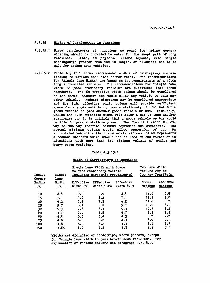
T.P*D*M.V*2.4
4.3.15 Widths of Carriageways in Junctions
4*3.15.1 Where carriageways at junctions go round low radius cornerswidening should be provided to cater for the swept path of longvehicles* Also, at physical island layouts, with singlecarriageways greater than 50m in length, an allowance should bemade for broken down vehicles.
4*3.15.2 Table 4*3.15.1 shows recommended widths of carriageway corres-ponding to various near side corner radii. The recommendationsfor "Single Lane Width" are based on the requirements of a 16.0mlong articulated vehicle. The recommendations for "single lanewidth to pass stationary vehicle11 are subdivided into threestandards. The 6m effective width column should be consideredas the normal standard and would allow any vehicle to pass anyother vehicle. Reduced standards may be considered appropriateand the 5.2m effective width column will provide sufficientspace for a goods vehicle to pass a stationary car but not for agoods vehicle to pass another goods vehicle or bus. Similarly,whilst the 4.3m effective width will allow a car to pass anotherstationary car it is unlikely that a goods vehicle or bus wouldbe able to pass a stationary car* The "two lane width for oneway or two way traffic" columns represent two standards* Thenormal minimum column would allow operation of the 16marticulated vehicle while the absolute minimum column representsa reduced standard which should not be used on bus routes or insituations with more than the minimum volumes of medium andheavy goods vehicles.
Table 4.3.15>1
Inside SingleCorner LaneRadius Width_(m) (a).
10 8.415 7.120 6.225 5*730 5.340 4.750 4.475 4.0100 3-8150 3.65
Width of Carriageways in Junctions
Single Lane Width with Spaceto Pass Stationary VehicleIncluding Hardstrip Provision(m)
EffectiveWidth 6m
10.99.68.78.27.87.26.96.56.36.0
EffectiveWidth 5.2m
9.58.27.36.86.45.85.45.25.25.2
EffectiveWidth 4.3m
8.47.16.25.75.34.74.34.34.34.3
Two Lane Widthfor One Way orTwo Way Traffic(m)
NormalMinimum
14.913.111*810*910.39.38.78.07.67.3
AbsoluteMinimum
9.59.08.78.58.27.97.77.47.37.0
Widths are exclusive of hardstrips, where present, exceptfor "single lane width to pass broken down vehicles". Forexplanation of various columns see paragraph 4.3*15.2.

T.P.D.M.V.2.4
4,3*16 Recommended Layouts
4.3.16.1 Based on the foregoing sections, Diagram Nos. 4.3*16*1 to4.3.16,14 have been prepared to show how the individual elementsare combined to produce typical junction layouts. It should bestressed (again) that the junction layouts are targets for whichthe designer should aim. Lesser provision may well be justifiedfor reasons of land take, topography, environmentalconsiderations or cost. However as many elements of the designas possible should be incorporated.
4.3.16.2 It should also be noted that the layouts can all cater for thedesign vehicle which is a 16.Om long articulated vehicle withsingle rear axle. Although many of the design elements are notrelated to vehicular turning properties, some, such as cornerradii, are and may be adjusted to suit a preferred designvehicle.
4.3.16*3 Particular comments on the typical junction layouts are asfollows :
Diagram No* 4.3.16.1
This shows suggested treatments for urban and rural simple T--junctions. The encroachment of long vehicles is annotated foreach layout. It should be stressed that the layouts shown areonly examples of kerb treatment. If land constraints do notpermit the use of the prescribed kerb layouts alternativecombinations of radii and straight should be tested to suit boththe particular land constraints and the swept path and turningradii of the design vehicle for that junction. For example itmay be decided that the most onerous vehicle which will use ajunction will be a 12m bus and the operating characteristics ofthis vehicle should then be used for design.
When using the urban layout catering for long vehiclesparticular care should be taken in the treatment of pedestrians.The designer should also be aware of potential problems frommultiple entry of small vehicles using the flared section.
For the rural junction layouts the metre hardstrips can beintroduced locally, if not existing throughout the route; and insuch cases the hardstrip on the side of the major road which isremote from the minor road is not required.
Diagram No. 4.3.16,2
This shows a 7.3m wide single two lane carriageway with a 3.5mwide shadow island and could be suitable for rural or semi urbansituations. This basic layout is adaptable for roads with metrestrips and particularly suitable for 10m wide main carriagewayswhere no widening is required. Where widening is required itcan be introduced a symmetrically to avoid utilities forexample.

T.P.D.M.V.2.4
If a pedestrian crossing is required the shadow island shouldnot be used as a central refuge.
Diagram No. 4.3»16*3
This shows a 7»3m wide single two lane carriageway with 5m wideshadow islands and a two lane approach on the minor road* Thislayout is appropriate to a more heavily trafficked situationthan the 3.5m wide islands* However shadow islands with widthsgreater than 3«5m should not be used on roads with design speedsabove 80 km/h.
If a pedestrian crossing is required the shadow island shouldnot be used as a central refuge,
Diagram No. 4.3*1.6.*J
This shows a 10m wide physical island on a single 2 lane road,appropriate to a busy rural junction. The 10m island (includingmetre strips) is capable of sheltering most vehicles turningright from the minor road. This type of layout (also depictedin Drawings 4.3-16.5, 11 and 12) requires a certain amount ofjudgement and caution to be exercised by the conflicting rightturning traffic movements.
A diverging lane is also shown and would be incorporated if theleft turn flow into the minor road was heavy.
Diagram No» *{.3*16.5
This shows a T-junction on a dual two lane carriageway with 10mcentral reserve and merging lane. It is appropriate with aheavy left turn from the minor road and heavy right turns.
Diagram No. 4.3.16.6
This shows two possible layouts for urban crossroads with theencroachment of long goods vehicles annotated on each. Asstated for Layout 1 the kerb treatments are only examples. Fornew junctions cross roads are only acceptable for low minor roadflows.
Diagram No. **.3.16«7
This shows two possible layouts for rural crossroads. Crossroadsshould be avoided for new construction in rural areas and thelayouts are presented for improvement to existing junctions. Thehardstrips should be introduced locally to emphasise thejunction if not already present on the route.
T.P.D.M.V.2.4
Diagram No. 4.3.16.8
This shows an urban crossroads with a 3.5m shadow island* Oneminor road has a two lane approach and the other a one laneapproach. This layout is not recommended for new constructionbut for existing junction improvement. Shadow islands shouldnot be used at crossroads in rural areas.
If a pedestrian crossing is required the shadow islands shouldnot be used as a central refuge,
Diagram Ho. 4.3*16.9
For new junctions staggered crossroads are far more preferableto straight crossroads. This layout shows a simple right leftstagger suitable for urban or rural roads.
Diagram No. 4.3.16.10
This shows right/left and left/right staggers suitable for urbansituations. In particular the right left stagger should not beused at high design speeds as it has been found that itencourages injudicious overtaking. The staggers shown are basedon the manoeuvring requirements of a long vehicle. Staggeredjunctions are always to be preferred to straight crossroads andright/left staggers are preferable to left /right staggers.
If a pedestrian crossing is required the shadow islands shouldnot be used as a central refuge.
Diagram No. 4.3*16.11
This shows a right /left stagger drawn for a higher design speedand more suitable for a rural situation. Indiscriminateovertaking is prevented by the use of physical islands,
Diagram No. 4. 3 * 16. 12
This shows the corresponding left/right stagger for the ruralsituation. The main carriageway is 7.3m wide as opposed to 10mwide in Diagram No. 4.3.16.11.
Diagram No. 4.3*16.13
This shows a T-junction situation on a rural climbing lanesection with minor road on the right of the up gradient. Shadowislands should not exceed 3.5m in width on climbing lanesections *
If a pedestrian crossing is required the shadow islands shouldnot be used as a central refuge.
T.P.D.M.V.2.4
Diagram No. 4.3.16.14
This shows two shadow island layouts for handling right hand andleft hand splays. The layouts are a target for the designer toaim at and it is envisaged that a compromise arrangement may benecessitated on land take considerations. The layouts areintended for improvements to existing junctions rather than newjunctions which should not be designed on a skew. Care shouldbe taken that the left turn into the major road on the righthand splay junction is not so easy as to encourage merging.
If a pedestrian crossing is required the shadow islands shouldnot be used as a central refuge.
Diagram No. *J.3.16.15
This shows the detailed design of the minor road channelisingislands applicable to many of the preceding junction layouts.The design procedure stipulated for rural road channelisingislands, although fairly straight-forward would need to besimplified for on-site setting out. It is suggested thereforethat the detailed design procedure is followed and then thegeometry simplified to facilitate setting out whilst stillmaintaining closely the deigned shape. It is felt that such aprocedure is preferable to simplifying the actual design stepswhich may lead to islands of unusual and may be unacceptableshape *
4.3.16.4 It will be noted from the drawing that rural channelisingislands are divided into T-junctions and crossroads and thefollowing points should be noted concerning each :
T-junctions (layout (a)}
(i) R, is tangential to the offset, d, from the minorroad centre line and the offside edge of the throughtraffic lane on the major road into which rightturning traffic from the minor road will turn.
(ii) Point A is established by describing an arc ofradius R1 + 2 concentric with H1 and joining itscentre with the point on its oircumfrence, where itcrosses the edge of the major road carriageway, witha straight line. A is the point where this straightline crosses the arc R1.
(iii) The circular arc R2 is tangential to the offsideedge of the major road offside diverging lane andalso passes through point A.
(iv) For splay junctions the centre line of the minorroad is turned with a radius of at least 50m to meetthe edge of the major road at right angles, and theisland should be about 15m long.

T*P.D*M.V.2.4
(v) For left hand splay junctions the offset d la 4.5m*
Crossroads (layout (b))
There are similarities with the design described under (a)but the following points should be noted :
(i) The long axis of the island is inclined at 5 degreesto the minor road centre line and the island isalways 3m wide*
(ii) The circular arc R1 has a radius of 11m and istangential to the left hand side of the island(viewed from the minor road approach) and the centreline of the major road. (In some cases where theminor road is inclined to the major road at anglesbetween 100 degrees and 110 degrees R1 will have tobe reduced to 8m to create a suitable island*)
(iii) The circular arc R2 has a radius of 11m and istangential to the major road centre line and theminor road centre line.
(iv) Where the minor road centre line is inclined to themajor road at angles less than 70 degrees H1 willnormally be 12m and R2 8m.
(v) Where the minor road centre line is inclined to themajor road at angles greater than 110 degrees R1will normally be 8m and R2 12m.
(vi) Where two splay minor roads meet at a crossroad theminor road centre lines should be offset relative toone another by approximately the width of oneisland*
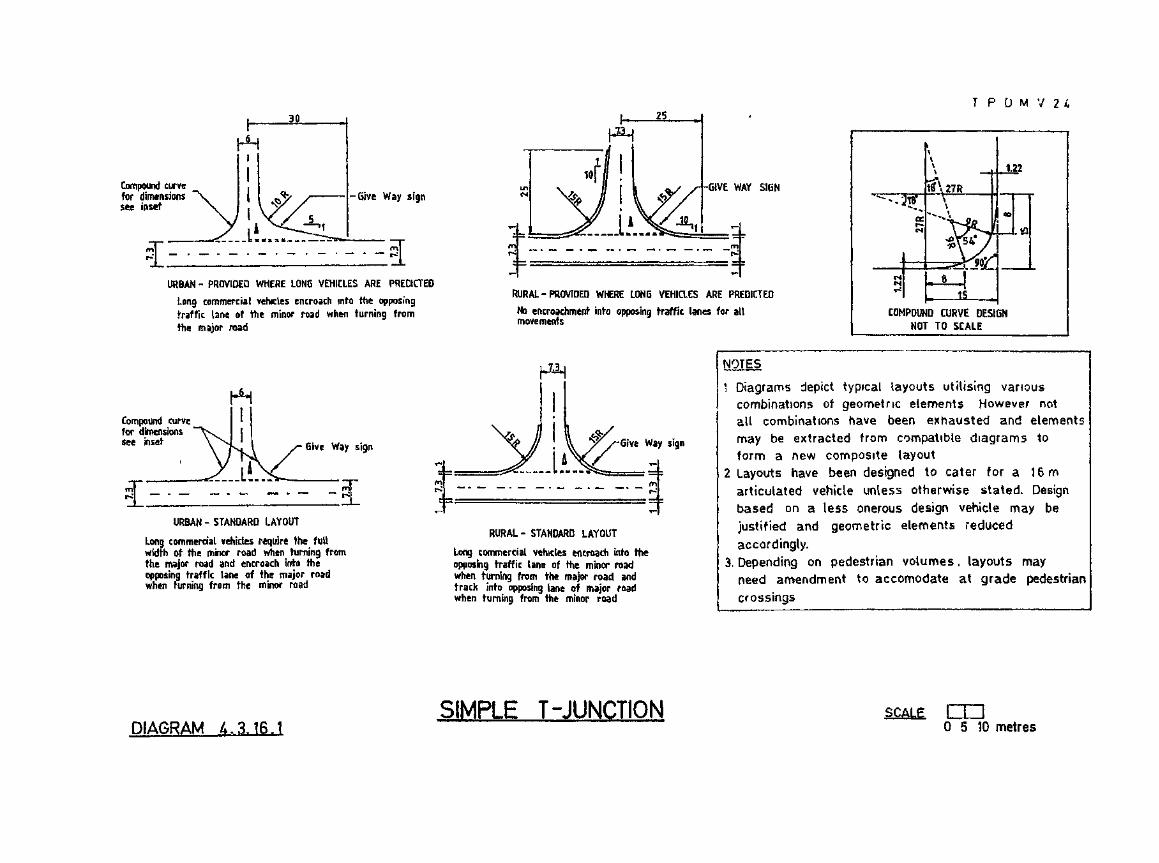
T P U M V 2
Compound curvefor dimensionssee inset
-Give Way sign
URBAN - PROVIDED WHERE LONG VEHICLES ARE PREDICTED
Long commercial vehicles encroach into the opposingtraffic lane of the minor road when turning fromthe major road
Compound curvefor dimensionssee inset Give Way sign
GIVE WAY SIGN
RURAL-PROVIDED WHERE LONG VEHICLES ARE PREDICTED
No encroachment into opposing traffic lanes for allmovements
Give Way sign
URBAN - STANDARD LAYOUT
Long commercial vehicles require the fullwidth of the minor road when turning fromthe major road and encroach into theopposing traffic lane of the major roadwhen turning from the minor road
RURAL - STANDARD LAYOUT
Long commercial vehicles encroach into theopposing traffic lane of the minor roadwhen turning from the major road andtrack into opposing lane of major roadwhen turning from the minor road
COMPOUND CURVE DESIGNNOT TO SCALE
NOTES
1 Diagrams depict typical layouts utilising variouscombinations of geometric elements However notail combinations have been exhausted and elementsmay be extracted from compatible diagrams toform a new composite layout
2 Layouts have been designed to cater for a 16marticulated vehicle unless otherwise stated. Designbased on a less onerous design vehicle may bejustified and geometric elements reducedaccordingly.
3. Depending on pedestrian volumes, layouts mayneed amendment to accomodate at grade pedestriancrossings
DIAGRAM A.3.16.1SIMPLE T-JUNCTION SCAIE. cm
0 5 10 metres
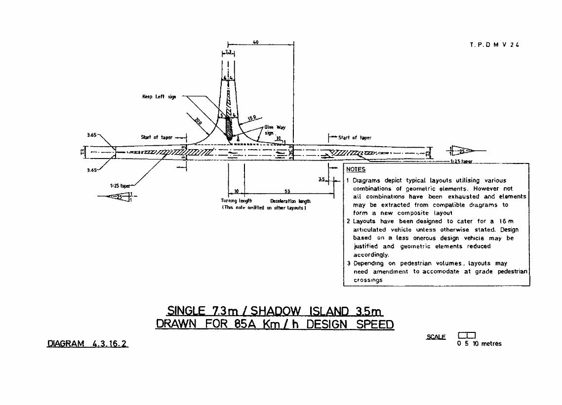
T. P.D M V 24
3.65
CE=E3.65-
1s25tepar„ 10 55
Turning length Deceleration length(This note omitted on other layouts)
1 Diagrams depict typical layouts utilising variouscombinations of geometric elements. However notall combinations have been exhausted and elementsmay be extracted from compatible diagrams toform a new composite layout
2 Layouts have been designed to cater for a 16marticulated vehicle unless otherwise stated Designbased on a less onerous design vehicle may bejustified and geometric elements reducedaccordingly.
3 Depending on pedestrian volumes, layouts mayneed amendment to accomodate at grade pedestriancrossings
SINGLE 7.3m/SHADOW ISLAND 3.5mDRAWN FOR 85A Km / h DESIGN SPEED
DIAGRAM A.3.t6.2.SCALE EUD
0 5 10 metres

T P D M V 2
3.65
CEE3
SHOWING TWO LANE APPROACH ON MINOR ROAD
NOTES
1 Diagrams depict typical layouts utilising variouscombinations of geometric elements. However notall combinations have been exhausted and elementsmay be extracted from compatible diagrams toform a new composite layout
2 Layouts have been designed to cater for a 16marticulated vehicle unless otherwise stated. Designbased on a less onerous design vehicle may bejustified and geometric elements reducedaccordingly.
3. Depending on pedestrian volumes, layouts mayneed amendment to accomodate at grade pedestriancrossings
SINGLE 7.3m / SHADOW ISLAND 5mDRAWN FOR 50/60 Km /h DESiGN SPEED
DIAGRAM £.3.16.3SCALE
0 5 10 metres
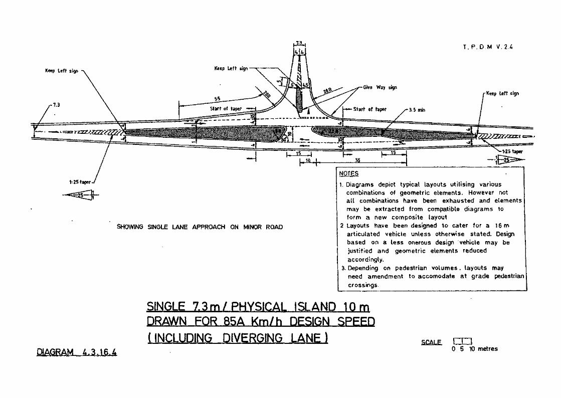
T. P.D.M V.2 .4
Keep Leff sign
Keep Uffr sign
1t25 taper
SHOWING SINGLE LANE APPROACH ON MINOR ROAD
NOTES
1. Diagrams depict typical layouts utilising variouscombinations of geometric elements. However notall combinations have been exhausted and elementsmay be extracted from compatible diagrams toform a new composite layout
2 Layouts have been designed to cater for a 16marticulated vehicle unless otherwise stated. Designbased on a less onerous design vehicle may bejustified and geometric elements reducedaccordingly.
3. Depending on pedestrian volumes, layouts mayneed amendment to accomodate at grade pedestriancrossings
SINGLE 7.3m/PHYSICAL ISLAND 10 mDRAWN FOR 85A Km/h DESIGN SPEED
(INCLUDING DIVERGING LANE) SCALE
DIAGRAM I*. 3.16.4ca0 5 10 metres
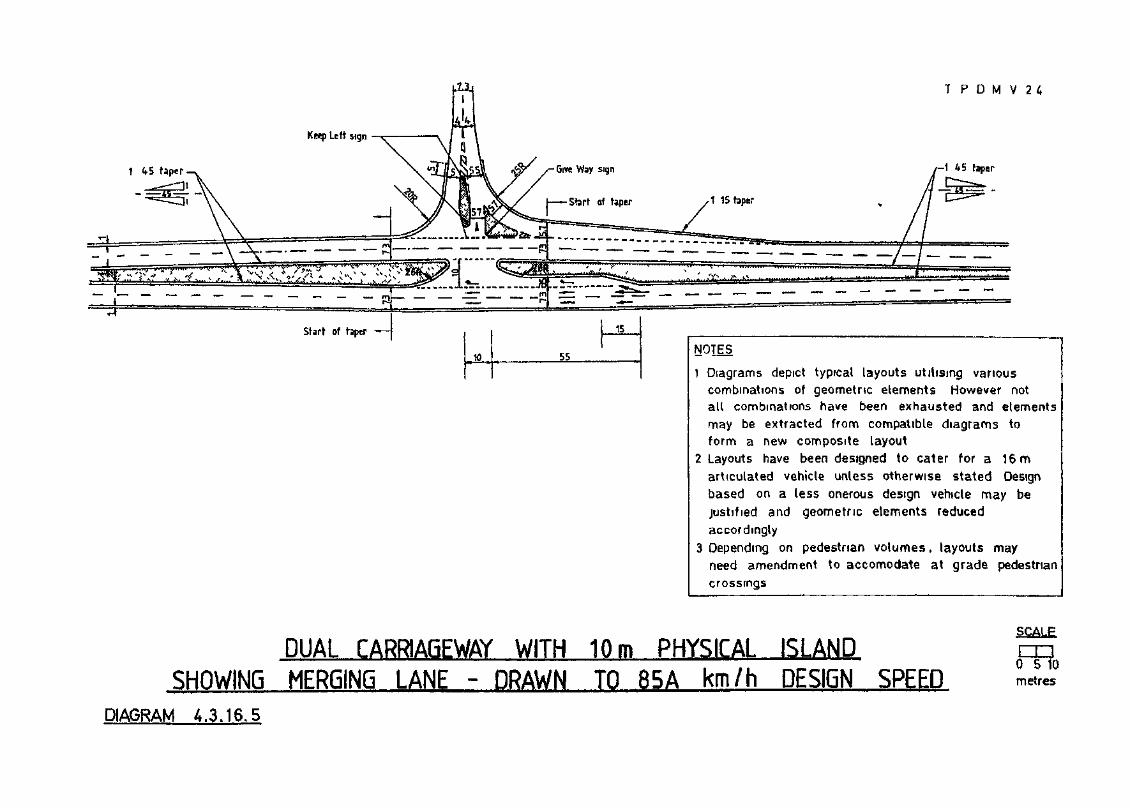
T P D M V 2
1 45 taper
1 Diagrams depict typical layouts utilising variouscombinations of geometric elements However notall combinations have been exhausted and elementsmay be extracted from compatible diagrams toform a new composite layout
2 Layouts have been designed to cater for a 16marticulated vehicle unless otherwise stated Designbased on a less onerous design vehicle may bejustified and geometric elements reducedaccordingly
3 Depending on pedestrian volumes, layouts mayneed amendment to accomodate at grade pedestriancrossings
DUAL CARRIAGEWAY WITH 10m PHYSICAL ISLANDSHOWING MERGING LANE - DRAWN TO 85A km/h DESIGN SPEED
DIAGRAM 4.3.16.5
SCALE
0 5 10metres

T. P D M V 2 4
Compound curvefor dimensionssee Layout- 1
Give Way sign Compound curve — Give Way sign
Give Way sign Compound curve Give Way sign —Compound curvefor dimensionssee Layout 1
30
STANDARD LAYOUT
long commercial vehicles require the full width of theminor road when turning from the major road and encroachinto the opposing traffic lane of the major road whenturning from the minor road
PROVIDED WHERE LONG VEHICLES ARE PREDICTED
Long commercial vehicles require the fullwidth of the minor road when turning fromthe major road
NOTES
1 Diagrams depict typical layouts utilising variouscombinations of geometric elements. However notall combinations have been exhausted and elementsmay be extracted from compatible diagrams toform a new composite layout
2 Layouts have been designed to cater for a 16marticulated vehicle unless otherwise stated. Designbased on a less onerous design vehicle may bejustified and geometric elements reducedaccordingly.
3 Depending on pedestrian volumes, layouts mayneed amendment to accomodate at grade pedestriancrossings
URBAN SIMPLE CROSSROADS
DIAGRAM 4.3.16.6SCALE CH3
0 5 10 metres

T P D M V . 2 4
Give Way sign
Keep Left sign
Give Way sign
15 metre wide kerbed island with 0.7$ metre corner radii
Keep Left si<
STANDARD LAYOUT
Long commericat vehicles encroachinto the opposing traffic lanewhen turning into the major roadand the minor road
PROVIDED WHERE LONG VEHICLES ARE PREDICTED
No encroachment into opposing trafficlanes for aU vehicle movements
1 Diagrams depict typical layouts utilising variouscombinations of geometric elements. However notall combinations have been exhausted and elementsmay be extracted from compatible diagrams toform a new composite layout
2 Layouts have been designed to cater for a 16marticulated vehicle unless otherwise stated, Designbased on a less onerous design vehicle may bejustified and geometric elements reducedaccordingly.
3 Depending on pedestrian volumes. layouts mayneed amendment to accomodate at grade pedestriancrossings
RURAL SIMPLE CROSSROADS
DIAGRAM 4.3.16.7SCALE. crn
0 5 10 metres

^ — - • — —" ~ ^ r
T. P. D.M V . 2 4
1 Diagrams depict typical layouts utilising variouscombinations of geometric elements. However notall combinations have been exhausted and elementsmay be extracted from compatible diagrams toform a new composite layout
2 Layouts have been designed to cater for a 16marticulated vehicle unless otherwise stated. Designbased on a less onerous design vehicle may bejustified and geometric elements reducedaccordingly.
3. Depending on pedestrian volumes > layouts mayneed amendment to accomodate at grade pedestriancrossings.
DIAGRAM 4.3.16.8
URBAN CROSSROADSWITH SHADOW ISLANDS
SCALE tm0 5 10 metres

T . P D M V 2
Give Way sign
Give Way sign
Long commercial vehicles require the full width ofthe minor road when turning from the major road
NOTES
1 Diagrams depict typical layouts utilising variouscombinations of geometric elements However notalt combinations have been exhausted and elementsmay be extracted from compatible dtagrams toform a new composite layout
2 Layouts have been designed to cater for a 16marticulated vehicle unless otherwise stated. Designbased on a less onerous design vehicle may bejustified and geometric elements reducedaccordingly.
3. Depending on pedestrian volumes 4 layouts mayneed amendment to accomodate at grade pedestriancrossings.
SIMPLE RIGHT / LEFT STAGGER
DIAGRAM /..3.16,9SCALE cm
0 S 10 metres

T . P .D .M.V 2 4
1:20 taper
RIGHT/LEFT STAfiFiFR
1 Diagrams depict typical layouts utilising variouscombinations of geometric elements. However notail combinations have been exhausted and elementsmay be extracted from compatible diagrams toform a new composite layout
2 Layouts have been designed to cater for a 16marticulated vehicle unless otherwise stated. Designbased on a less onerous design vehicle may bejustified and geometric elements reducedaccordingly.
3 Depending ' on pedestrian volumes, layouts mayneed amendment to accomodate at grade pedestriancrossings
DIAGRAM 4.3.16.1Q.A
URBAN RIGHT/LEFT AND LEFT/RIGHT STAGGERSSINGLE 7.3m WITH 3.5 m SHADOW ISLAND
SCALg rn0 5 10 metres

T. P.D M V. 2 A
LEFT/RIGHT STAGGER
1. Diagrams depict typical layouts utilising variouscombinations of geometric elements. However notall combinations have been exhausted and elementsmay be extracted from compatible diagrams toform a new composite layout
2. Layouts have been designed to cater for a 16marticulated vehicle unless otherwise stated. Designbased on a less onerous design vehicle may bejustified and geometric elements reducedaccordingly,
3. Depending on pedestrian volumes, layouts mayneed amendment to accomodate at grade pedestriancrossings
URBAN RIGHT/LEFT AND LEFT/RIGHT STAGGERSSINGLE 7.3m WITH 3.5m SHADOW ISLAND
SCALE
DIAGRAM 4.3.16.10.Bcrfl10 metres

T. P .D .M.V .2 .4
1*25 taper
1 Diagrams- depict typical layouts utilising variouscombinations of geometric elements. However notail combinations" have been exhausted and elementsmay be extracted from compatible diagrams toform a new composite layout
2 Layouts have been designed to cater for a 16marticulated vehicle unless otherwise stated, Designbased on a less onerous design vehicle may bejustified and geometric elements reducedaccordingly,
3 Depending on pedestrian volumes. layouts mayneed amendment to accomodate at grade pedestriancrossings
RIGHT / LEFT STAGGER-10m PHYSICAL ISLANDDRAWN FOR 85A Km / h DESIGN SPEED
DIAGRAM 4.3.16.11SCALE
0 5 10 metres

T . P . D . M . V . 2 4
1:25 taptrr 1:25 taper
NOTES
1 Diagrams depict typical layouts utilising variouscombinations of geometric elements. However notall combinations have been exhausted and elementsmay be extracted from compatible diagrams toform a new composite layout
2 Layouts have been designed to cater for a 16marticulated vehicle unless otherwise stated. Designbased on a less onerous design vehicle may bejustified and geometric elements reducedaccordingly.
3. Depending on pedestrian volumes, layouts mayneed amendment to accomodate at grade pedestriancrossings
LEFT / RIGHT STAGGER -10m PHYSICAL ISLANDDRAWN FOR 85A km/h DESIGN SPEED SCAIE,
DIAGRAM 4.3.16.120 5 10 metres

T P D M V 2 4
125 taper
•UphiU gradient10
NOTES
1 Diagrams depict typical layouts utilising variouscombinations of geometric elements However notail combinations have been exhausted and elementsmay be extracted from compatible diagrams toform a new composite layout
2 Layouts have been designed to cater for a 16marticulated vehicle unless otherwise stated Designbased on a less onerous design vehicle may bejustified and geometric elements reducedaccordingly
3 Depending on pedestrian volumes, layouts mayneed amendment to accomodate at grade pedestriancrossings
CLIMBING LANE THROUGH T JUNCTIONDRAWN FOR 85A Km/h DESIGN SPEED
DIAGRAM 4.3.16.13SCALE CEH
0 5 10 metres


R-50Edge of major carriageway 1'20
Give Way $J Left sign
3.65- -1
T. P.D.M.V. 2.4
;E ; ." _ is -".
3.65 Start of taper—H —Start of taper
40
RIGHT HAND SPLAY JUNCTION (93*110*}
1. Diagrams depict typical layouts utilising variouscombinations of geometric elements. However notait combinations have been exhausted and elementsmay be extracted from compatible diagrams toform a new composite layout.
2. Layouts have been designed to cater for a 16marticulated vehicle unless otherwise stated. Designbased on a less onerous design vehicle may bejustified and geometric elements reducedaccordingly,
3. Depending on pedestrian volumes, layouts mayneed amendment to accomodate at grade pedestriancrossings.
SKEW MINOR ROAD3.5m SHADOW ISLAND
DES. SPEED 70 Km/hDIAGRAM 4.3.16.UB
SCALE. f"T"l0 5 10 metres


T.P.D.M*V*2.4
Signal Controlled Junctions
The performance of signal controlled junctions in comparison toother types of junction is dealt with in Section 4*2 of thisChapter and summarised in Table 4*2.10*1* For a detailedaccount of traffic signals, Volume 4 of this Manual is dedicatedentirely to the subject and the reader is referred thereto.

T*P*D.M.V*2.4
4.5 Roundabouts
4-5.1 Introduction
4*5.1*1 Roundabouts could be considered as a specialized forms ofPriority Junction. Unlike normal priority junctions, however,where major road traffic receives continuous priority, withroundabouts the flow entering the junction from all arms givespriority to vehicles already in the junction* Roundabouts arethus well suited to situations of balanced flow. Also, becauseright turns, and all other movements, are broken down into aleft turn entry and a left turn exit, roundabouts are wellsuited to flows containing a high proportion of right turningvehicles.
4.5.1.2 There are three basic types of roundabout namely : Normal, Miniand Double. Other forms of roundabouts which are variants ofthese three basic types are Ring Junctions, Grade SeparatedRoundabouts and Signalized Roundabouts.
4.5*1*3 A normal roundabout can be considered as a one-way circulatorycarriageway around a kerbed central island 4m or more indiameter and usually with flared approaches to allow multiplevehicle entry.
4.5*1.4 A mini roundabout consists of a one-way circulatory carriagewayaround a flush or slightly raised circular marking less than 4min diameter and with or without flared approaches.
4.5.1*5 A double roundabout is a single junction with two normal or miniroundabouts either contiguous or connected by a central linkroad or kerbed island.
4.5.1*6 A grade separated roundabout junction is defined as one whichincludes a roundabout which has at least one entry road, via aninterconnecting slip road, from a road at a different level.
4.5.1*7 A ring junction retains the large central island characteristicof a roundabout but the usual one-way circulation of vehicles isreplaced by two-way circulation with three-arm mini roundaboutsand/or traffic signals controlling the junction with eachapproach arm.
4.5.1.8 A signalized roundabout is a normal roundabout with trafficsignals installed on one or more of the approach arms.
4.5.2 Normal Roundabouts
4.5.2.1 Normal roundabouts encompass a large range of central islandsizes including both of what formerly were referred to as smallroundabouts and conventional roundabouts. The long parallelsided weaving sections, required before the offside priorityrule was introduced, have now been replaced with shorter widersections and much greater importance is attached to the geometryof the entry. The revised geometrical requirements effectivelyresult in a much reduced land take when compared with the formerdesigns and this fact is of particulars significance in theTerritory where land prices are high.
4.5*2.2 The number of entries recommended for a normal roundabout isthree or four* Roundabouts perform particularly well with threeentries and balanced traffic flows. If the number of entries isgreater than four, driver comprehension is affected and theroundabout becomes larger with the probability that highercirculatory speeds will be generated. In these circumstancesdouble roundabouts should be considered as a potential solution.

T.P.D.M.V.2.4
4.5*3 Mini Roundabouts
4.5.3.1 Mini roundabouts can be extremely effective in improvingexisting urban junctions that experience capacity problems.Their economical use of land recommends them for many situationsin Hong Kong particularly where T-junctions with balancedtraffic flows exist. They should only be used when allapproaches are subject to a 50 km/h speed limit. Above thisspeed problems will arise from motorists not being aware,sufficiently early, that they are approaching a roundabout* Inthis respect great attention should be paid to the layout andsigning.
4.5*3-2 As with other roundabouts, vehicle paths should be deflected toreduce their speed within the roundabout. Physical deflectionon the approach may not be possible with mini roundabouts, owingto space constraints, and in such cases road markings and smalldeflection islands should be used. These islands should be freeof all street furniture except the keep left bollards and otheressential signs. Drawing No. 4.5.3.1 shows the use ofdeflection islands at both normal and mini roundabouts*
4.5.3.3 The central island (1 to 4 m diameter) should be as large aspossible in relation to the site and domed up to a maximumheight of 125mm at the centre. The dome should be completelywhite and reflectorised. Domes surfaced with natural stonematerials etc. do not show sufficient contrast with thesurrounding road surface. A right of omni-directionalreflective road studs around the periphery of the dome has beenfound effective in increasing conspicuity at night. Nobollards, signs, lighting columns or other street furnitureshould be placed on the dome.
4.5.3-4 Where space is very restricted the repeated over-running of thecentral island by long vehicles will be unavoidable and in suchcases the dome may be replaced by a circular marking with itsperiphery delineated by reflective road studs.

NORMAL ROUNDABOUT T.P.O.M.V. 2.4.
TRAFFIC DEFLECTION ISLAND
MINI ROUNDABOUTS
TRAFFICDEFLECTIONISLANDS
HATCHED TRAFFICDEFLECIION 'ISLAND
II
II KERBEO TRAFFICDEFLECTION ISLAND
(a) 4-ARM JUNCTION WITHFUREO APPROACHES I N
Ibt 4-ARM JUNOION WnHOUTFLARED APPROACHES
DEFLECTION ISLANDS AT NORMAL/MINI RDBTS.DIAGRAM 45.3.1.

T.P.D-M.V.2.4
4.5.4 Dpuble Roundabouts
4*5.4*1 As mentioned in paragraph 4.5*2.2, where a junction has morethan four entries, a double roundabout may be preferable to anormal roundabout. In such a situation a double roundaboutachieves better capacity with acceptable safety characteristicsin conjunction with a more efficient use of space. Othersituations where double roundabouts can be particularly usefulinclude :
(a) The improvement to an existing staggered junctionwhere it avoids the need to realign one of theapproach roads thereby achieving a considerable savingin construction costs;
(b) At unusual or a symmetrical junctions, such asscissors junctions, where the installation of a singleisland roundabout would require extensive realignmentof the approaches or excessive land take (see DiagramNo. 4*5.4.1);
(c) At the joining of two parallel routes separated by afeature such as a river or railway line;
(d) At existing crossroads where it is desirable toseparate opposing right turning movements allowingthem to pass nearside to nearside (see Diagram No*4.5.4.1); and
(e) At overloaded single roundabouts where, by reducingthe circulating flow past critical entries, itincreases capacity*
4*5.4.2 Where the double roundabout is comprised of, mini roundaboutsthey should only be used where all the approaches are subject toa 50 km/h speed limit.

T.P.O.M.V. 2.4.
CONTIGUOUS DOUBLE ROUNDABOUTFOR SITUATIONS DESCRIBED IN PARA. 4.5.4.1. Id
DIAGRAM 4.5.4.1,
DOUBLE ROUNDABOUT WITH SHORT CENTRAL LINK ROAD(FOR SITUATIONS DESCRIBED IN PARA 4.S 4 - 1 .
TYPICAL DOUBLE ROUNDABOUT LAYOUTS

T.P.D*M*V.2*4
4*5.5 Other Types of Roundabout
4*5*5*1 Variations on the three basic forms of roundabout discussedabove include Grade Separated Roundabouts, Ring Junctions andSignalized Roundabouts. The most common forms of roundaboutused at grade separated junctions are the two bridge type andthe dumbell type, both of which are shown in Diagram No*4.5.5.1* The two bridge type suffers from its large size whichincreases speeds within the circulatory section, therebyreducing capacity and safety. Design of this type shouldtherefore be made as compact as possible. The dumbellroundabout design has the advantage of compactness and lowconstruction costs*
4.5.5*2 The conversion to ring junction is an effective solution forvery large roundabouts which exhibit entry problems. Studieshave shown that ring junction layouts can eliminate congestionwithout reducing safety* There are no existing roundabouts inthe Territory however, which are large enough for considerationto converting to ring junction control and it is unlikely thatsuch layouts will ever form part of our road network*
4.5.5.3 Signalized roundabouts, in certain circumstances, may constitutea most useful design tool. The need for signals at a roundaboutnormally stems from problems associated with one or moreparticularly dominant flows which tends to defeat the selfregulating property of the roundabout. By installing trafficsignals entry to the roundabout can be regulated thus creatingentry opportunities for the non dominant flows.

T.P.D.M.V.2.4.
TWO BRIDGE ROUNDABOUT AT GRADE SEPARATED INTERCHANGE
DIAGRAM 4.5.5.1.
GRADE SEPARATED INTERCHANGE WITH ONE BRIDGEAND TWO ROUNDABOUTS -'DUMBELL INTERCHANGE'
TYPES OF GRADE SEPARATED ROUNDABOUTS
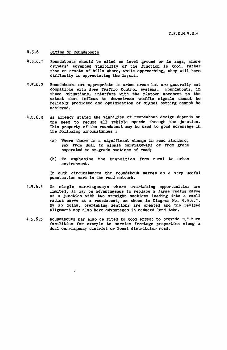
T.P.D.M.V.2.4
4.5.6 Siting of Roundabouts
4*5*6.1 Roundabouts should be sited on level ground or In sags, wheredrivers1 advanced visibility of the junction is good, ratherthan on crests of hills where, while approaching, they will havedifficulty in appreciating the layout,
4.5.6*2 Roundabouts are appropriate in urban areas but are generally notcompatible with Area Traffic Control systems* Roundabouts, inthese situations, interfere with the platoon movement to theextent that inflows to downstream traffic signals cannot bereliably predicted and optimisation of signal setting cannot beachieved*
4*5.6*3 As already stated the viability of roundabout design depends onthe need to reduce all vehicle speeds through the junction*This property of the roundabout may be used to good advantage inthe following circumstances :
(a) Where there is a significant change In road standard,say from dual to single carriageways or from gradeseparated to at-grade sections of road;
(b) To emphasise the transition from rural to urbanenvironment.
In such circumstances the roundabout serves as a very usefulpunctuation mark in the road network.
4.5*6,4 On single carriageways where overtaking opportunities arelimited, it may be advantageous to replace a large radius curveat a junction with two straight sections leading into a smallradius curve at a roundabout, as shown In Diagram No. 4.5*6*1.By so doing, overtaking sections are created and the revisedalignment may also have advantages in reduced land take.
4.5.6.5 Roundabouts may also be sited to good effect to provide "0" turnfacilities for example to service frontage properties along adual carriageway district or local distributor road.

TP.D.M.V 2.4.
STRAIGHT SECTION PROVIDES
OVERTAKING OPPORTUNITY
INSIDE KERB OF LARGE
RADIUS CURVE (NO
OVERTAKING OPPORTUNITY)
USE OF ROUNDABOUT TO CHANGE ALIGNMENT
DIAGRAM 4.5.6.1

T.P.D.M.V.2.4
*J.5.7 Safety at Roundabouts
4.5*7.1 In general a well designed roundabout will cause fewer accidentsthan a signal controlled junction handling the same volume oftraffic. The severity of accidents at roundabouts is also lowerthan that of all other junction types and mid link locations.
4.5.7.2 The most important factor affecting safety at roundabouts is theentry and circulatory speeds. High speeds are normallyassociated with large roundabouts having excessively long and/orwide circulatory carriageways, but they can also be caused atsmaller roundabouts by inadequate entry deflection. Otherfactors inducing high speeds at roundabouts include : very acuteentry angles which encourage fast merging, poor visibility tothe "Give Way* line and poorly designed and located warning andadvanced direction signs.
4.5.7.3 Measures which have been found to improve safety at roundaboutsinclude, the provision of appropriate levels of skid resistanceon the approaches an circulatory carriageway; the avoidance ofabrupt and excessive super-elevation in the entry region; thereduction of excessive entry width by hatching or physicalmeans; and the provision of "Reduce Speed Now11 signs and "YellowBar" markings on the approaches* Volume 3 Chapter 5 givesdetailed information on the use of "Yellow Bar* markings.
4.5.7.4 Though roundabouts have an impressive overall safety record formost vehicle types this does not apply equally to two wheeledvehicles. Statistics from the United Kingdom show that accidentinvolvement rates for two-wheeled vehicles, expressed in termsof accidents per road user movement, are 10-15 times those ofcars; with pedal cyclists having a slightly higher accident ratethan motor cyclists. It is useful to note that different typesof roundabouts exhibited different results in this respect. Forexample, normal roundabouts with small central islands andflared entries have accident rates which are about twice thoseof normal roundabouts with large central islands and unflaredentries. This relationship appears to apply consistently forall types of vehicle,
4.5.7.5 Heavy goods vehicle accidents at roundabouts frequently involvethe shedding of loads. Roundabouts, where this problem has beenencountered usually exhibit one or more of the followingfeatures : inadequate entry deflection, long straight sectionsof circulatory carriageway, sharp turns into exits, excessiveorossfall changes on the circulatory carriageway and excessiveadverse orossfall on a nearside lane of the circulatorycarriageway.
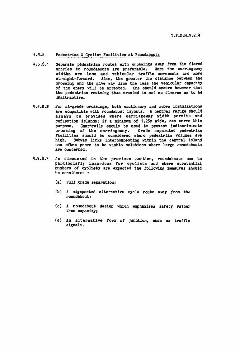
T.P.D«M.V*2.4
4*5.8 Pedestrian t Cyclist Facilities at Roundabouts
4.5.8.1 Separate pedestrian routes with crossings away from the flaredentries to roundabouts are preferable. Here the carriagewaywidths are less and vehicular traffic movements are morestraight-forward. Also, the greater the distance between thecrossing and the give way line the less the vehicular capacityof the entry will be affected. One should ensure however thatthe pedestrian routeing thus created is not so diverse as to beunattractive*
4.5*8.2 For at-grade crossings, both cautionary and zebra installationsare compatible with roundabout layouts. A central refuge shouldalways be provided where carriageway width permits anddeflection islands; if a minimum of 1.25m wide, can serve thispurpose. Guardrails should be used to prevent indiscriminatecrossing of the carriageway. Grade separated pedestrianfacilities should be considered where pedestrian volumes arehigh. Subway links interconnecting within the central islandcan often prove to be viable solutions where large roundaboutsare concerned.
4.5*8.3 As discussed in the previous section, roundabouts can beparticularly hazardous for cyclists and where substantialnumbers of cyclists are expected the following measures shouldbe considered :
(a) Full grade separation;
(b) A signposted alternative cycle route away from theroundabout;
(c) A roundabout design which emphasises safety ratherthan capacity;
(d) An alternative form of junction, such as trafficsignals.

T.P.D.M.V.2.4
4.5.9 Capacity of Roundabouts
4*5.9.1 What were previously referred to as "conventional roundaboutsw
consisted of large central islands with long parallel sidedweaving sections. The capacity of the roundabout was measuredin terms of the capacity of its individual weaving sectionsusing Wardropfs Formula. With the introduction of small andmini roundabouts the emphasis was placed on shorter widerweaving sections (in fact little weaving takes place) and flaredapproaches. The capacity of this type of roundabout wascalculated for the junction as a whole based on the basic roadwidths and areas of widening at the junction. These formulaehave now been superseded by a predictive equation, giving thecapacity of each entry to the roundabout, which is applicable toall types of roundabout.
4.5*9*2 Since the introduction of the offside priority rule trafficwaiting to enter a roundabout on one am has to give priority totraffic already on the circulatory carriageway crossing theentry. Consequently, the entry capacity decreases as thecirculating flow increases, since there are then feweropportunities for waiting drivers to enter the circulation.When entry opportunities do present themselves the number ofvehicles which are able to avail themselves of the opportunitydepends on the entry width, the circulatory width, the entryangle and other geometric characteristics of the roundaboutlayout. The predictive equations are thus stated in terms ofthe circulating flow and the geometric parameters, and are basedon multiple regression analyses from observations at a largenumber of sites in the United Kingdom.
4.5.9*3 In evaluating a proposed layout, the design flow for each entry,derived as described in para* 4.2.4, should be compared with thecalculated capacity to produce a design flow/capacity ratio(DFC). The entry capacity is defined as the maximum in-flowfrom an entry when the demand flow is sufficient to cause steadyqueueing in the approach. A DFC ratio of 100$ would thereforeindicate continual queueing and could not be consideredacceptable. A DFC ratio of 8535, indicating that queueing wouldtheoretically be avoided in 85% of cases, can be consideredreasonable. A DFC of 70% indicates that queueing will beavoided in 95?! of cases. The acceptable value of DFC will varyin relation to individual circumstances. For example in asituation where future improvement to the junction would beimpossible a lower DFC than otherwise considered reasonable mayneed to be achieved.
T.P.D.M.7.2JI
4*5.9*** The predictive equation for roundabout capacity together withdefinitions of parameters and explanatory diagrams is given inAppendix 2* It will be readily appreciated however that theprocess of computation is necessarily iterative in nature* As acapacity for one entry varies so does the potential circulatingflow across a different entry with a subsequent change in thecapacity of that entry, and so on. This iterative process isbest suited to computer application and the program ARCADY,which should be available in the Territory in the near future,can carry out the computation. This program will calculatequeue lengths and delays for each time segment. In the absenceof the computer program the computation can be carried outmanually to give a preliminary assessment of layout viabilityand a worked example is included in Appendix 2.

T.P.D.M.V.2.4
4.5.10 General Layout Requirements
4.5.10.1 The principal objective of roundabout desigc is to secure thesafe interchange of traffic between crossing and weaving trafficstreams with minimum delay. This is achieved by a combinationof the geometric layout features described in the followingparagraphs. As relationships between aspects of design are notalways mutually compatible, design becomes a trade off betweenoperational efficiency, minimising delays and achieving safety.
4.5.10.2 Where geometric design parameters are speed related, at existingjunctions or new junctions on existing roads, the measured 85percentile speed should be used, rounded up to the next highestdesign speed step* For completely new junctions the designspeed of the roads should be used.
4.5.10.3 The geometric parameters described in subsequent paragraphs aredepicted in Figures 1-5 of Appendix 2 with accompanying detaileddescription*

T.P.D.M.V.2.4
4.5.11 Visibility
4.5.11.1 The following guidelines represent good practice concerning theprovision of visibility and when not complied with there is needfor additional signing to alert drivers of all vehicles topotential hazards. Visibility distances should be measuredbetween a driver's eye height of 1.05m and an object height of1.05m, both measured from the centre line of each lane.
4.5.11.2 The forward visibility at the approach to a roundabout shall notbe less than that shown in Table 4.5.1K1 below (c.f. Table3.3.5.1 in Chapter 3 of this volume). The visibility distanceshould be measured to the "Give Wayn line as shown in DiagramNo. 4.5.11.1.
Table 4.5.11.1
Sight Distances
Design Speed (km/h) 100 85 70 60 50Desirable Minimum (m) 225 165 125 95 70Absolute Minimum (m) 165 125 95 70 50
4.5*11.3 As drivers get closer to the "Give ¥ayn line they should be ableto see the full width of the circulatory carriageway, to theirright, as far as the previous entry or for a distance of 50m,measured along the centre of the circulatory carriageway,whichever is the lesser* This visibility should be availablefrom the centre of the offside lane at a distance of 15m backfrom the "Give Way" line as shown in Diagram No. 4.5.11.2.
4.5.11.4 In addition to the visibility to the right, approachingmotorists also require visibility ahead which similarly shouldextend to the next exit or for a distance of 50m, measured alongthe centre of the circulatory carriageway, whichever is thelesser. This visibility should be available from the centre ofthe nearside lane at a distance of 15m back from the "Give Way"line as shown in Diagram No. 4.5.11.3.
4.5.11.5 Drivers of all vehicles circulating on a roundabout should beable to see the full width of the circulatory carriageway aheadof them as far as the next exit or for a distance of 50m,whichever is the lesser. This visibility should be checked froma point 2m in from the central island as shown in Diagram No,4.5.11.4.

T.P.D.M.V.2.4
4.5.11.6 Where a pedestrian crossing is located across the entry to aroundabout, drivers approaching the roundabout should havevisibility to the crossing of a distance not less than that
• shown in Table 4.5.11.1. Additionally, drivers at the ttGiveWay*1 line of one entry should be able to see the full width of acrossing located at the next entry if this is within 50m of theroundabout. This requirement, illustrated in Drawing No.4.5*11.5, may be difficult to achieve in urban areas owing toadjacent roadside development*
4.5.11.7 Particular attention should be paid to visibility requirementsat grade separated junctions to ensure that visibility is notobstructed by safety fences or bridge parapets in the case ofelevated roundabouts and by flyover abutments in the case of aflyover.
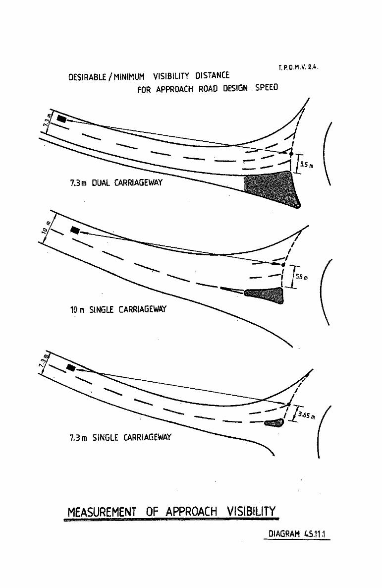
DESIRABLE/MINIMUM VISIBILITY DISTANCE
FOR APPROACH ROAD DESIGN SPEED
T.P.O.M.V.2.4.
7.3m DUAL CARRIAGEWAY
10m SINGLE CARRIAGEWAY
7.3m SINGLE CARRIAGEWAY
MEASUREMENT OF APPROACH VISIBILITY
DIAGRAM 45.11.1

T.P.O-M.V. 2.4.
DIAGRAM 4.5.11-?
MINIMUM AREA OVERWHICH VISIBILITYSHOULD BE OBTAINEDFROM VIEWPOINT
VISIBILITY TO THE RIGHT REQUIRED AT ENTRY

T.P.O.M.V. 2 .4.
HALF LANE WIDTH
MINIMUM AREA OVER WHICHVISIBILITY SHOULD BEOBTAINED FROM VIEWPOINT£>*
DIAGRAM 4.5.11.3.
FORWARD VISIBILITY REQUIRED AT ENTRY

T.P.O.M.V.2.4.
MINIMUM AREA OVER WHICH
VISIBILITY SHOULD BE OBTAINEDFROM VIEWPOINT
DIAGRAM 4.5.11.4.
CIRCULATORY VISIBILITY REQUIRED

T.RD.M.V.2.4 .
MINIMUM AREA OVER WHICH UNOBSTRUCTED VISIBILITY
IS REWIRED FROM VIEWPOINT 3t> WHEN CROSSING
IS WITHIN 50m
HALF LANEWIDTH
DIAGRAM 4.5.11.5PEDESTRIAN CROSSING
VISIBILITY REQUIREMENTS
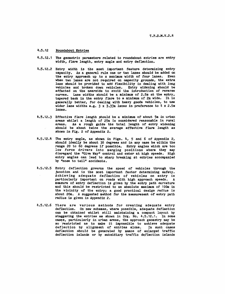
T.P.D.M.V.2.4
4.5*12 Roundabout Entries
4.5.12.1 The geometric parameters related to roundabout entries are entrywidth, flare length, entry angle and entry deflection.
4.5.12.2 Entry width is the most important feature determining entrycapacity. As a general rule one or two lanes should be added onthe entry approach up .to a maximum width of four lanes. Evenwhen two lanes are not required on capacity grounds, the extralane should be provided to add flexibility in dealing with longvehicles and broken down vehicles. Entry widening should beeffected on the nearside to avoid the Introduction of reversecurves. Lane widths should be a minimum of 2.5m at the entry,tapered back in the entry flare to a minimum of 2m wide. It isgenerally better, for dealing with heavy goods vehicles, to usewider lane widths e.g. 3 x 3.33m lanes in preference to 4 x 2.5mlanes.
4.5.12.3 Effective flare length should be a minimum of about 5m in urbanareas whilst a length of 25m is considered reasonable in ruralareas. As a rough guide the total length of entry wideningshould be about twice the average effective flare length asshown in Fig. 2 of Appendix 2.
4.5.12.4 The entry angle, as shown in Figs. 4, 5 and 6 of Appendix 2,should ideally be about 30 degrees and in any case be within therange 20 to 60 degrees if possible. Entry angles which are toolow force drivers into merging positions where they maydisregard the "Give Wayn control and enter at high speeds. Highentry angles can lead to sharp breaking at entries accompaniedby wnose to tail" accidents.
4.5.12.5 Entry deflection governs the speed of vehicles through thejunction and is the most important factor determining safety.Achieving adequate deflection of vehicles on entry isparticularly important on roads with high approach speeds. Ameasure of entry deflection is given by the entry path curvatureand this should be restricted to an absolute maximum of 100m inthe vicinity of the entry; a good practical design radius isabout 20m. A suggested method for the measurement of entry pathradius is given in Appendix 2.
4.5.12.6 There are various methods for creating adequate entrydeflection. On new schemes, where possible, adequate deflectioncan be obtained whilst still maintaining a compact layout bystaggering the entries as shown in Drg. No. 4.5.12.1. In somecases, particularly in urban areas, the approach geometry may beso 'restricted as to make it impossible to achieve adequatedeflection by alignment of entries alone. In such casesdeflection should be generated by means of enlarged trafficdeflection islands or by subsidiary traffic deflection islands

T.P.D.M.V.2.4
in the entry as shown in Diag. Sos* 4.5*12.2 and 3* Subsidiarydeflection islands may be surfaced in white reflective materialand circumscribed with reflecting road studs to improve theirconspieuity.
*J.5*12.7 It is not recommended that entry deflection be generated bysharply deviating the approach road to the right and then to theleft at entry. Approach curves should be fairly gentle, andadequately signed if they fall below the minimum standardsappropriate to the design speed.

TP.O.M.V 2.4.
Note'cosy exits
DIAGRAM 4.5.12.1
ENTRY DEFLECTION Bf
STAGGERING APPROACH ROADS

r .P .O.M.V.2>.
ENTRY DEFLECTION ACHIEVED BYUSING TRAFFIC DEFLECTION ISLANDS
DIAGRAM 4.5.12.2,

l.P.Q.M.V. 2.4.
NOT GREAIERTHAN 75mm
SU8SIOJARY TRAFFICDC FLECTION ISLAND
DIAGRAM 45.123.
ENTRY DEaECTtON ACHIEVED BYSUBSIDIARY TRAFFIC DEFLECTION ISLANDS

T.P.D.M.V.2.4
4.5*13 Roundabout Exits
4.5.13.1 A nearside kerb radius of about 40m at the mouth of the exit isdesirable, but in any case this radius should not be below 20m.
4.5*13.2 The beginning of the exit should ideally be one lane wider thanthe downstream link* For example if the down stream link is adual 2 the exit width should be 10m to 11m. The extra widthshould be reduced on the nearside at a taper of 1:15 to 1:20,though this may be extended on an uphill gradient to avoidintermittent congestion* Within single carriageway exits aminimum of 6m should be maintained throughout the length of anyphysical island to accommodate traffic passing a broken downvehicle.

T.P«D.M,V.2,4
4.5.14 The Circulatory Carriageway
4.5*14*1 The width of the circulatory carriageway should be constant andlie between 1.0 and 1.2 times the maximum entry width.
4*5.14.2 The circulatory carriageway should, if possible, be circular inplan, avoiding deceptively tight bends. Additionally, shortlengths of reverse curve between entry and adjacent exit shouldbe avoided by linking entry and exit curves or joining them witha straight. At T-junction configurations however, as shown inDiagram No* 4.5*11.2, reverse curvature may result.
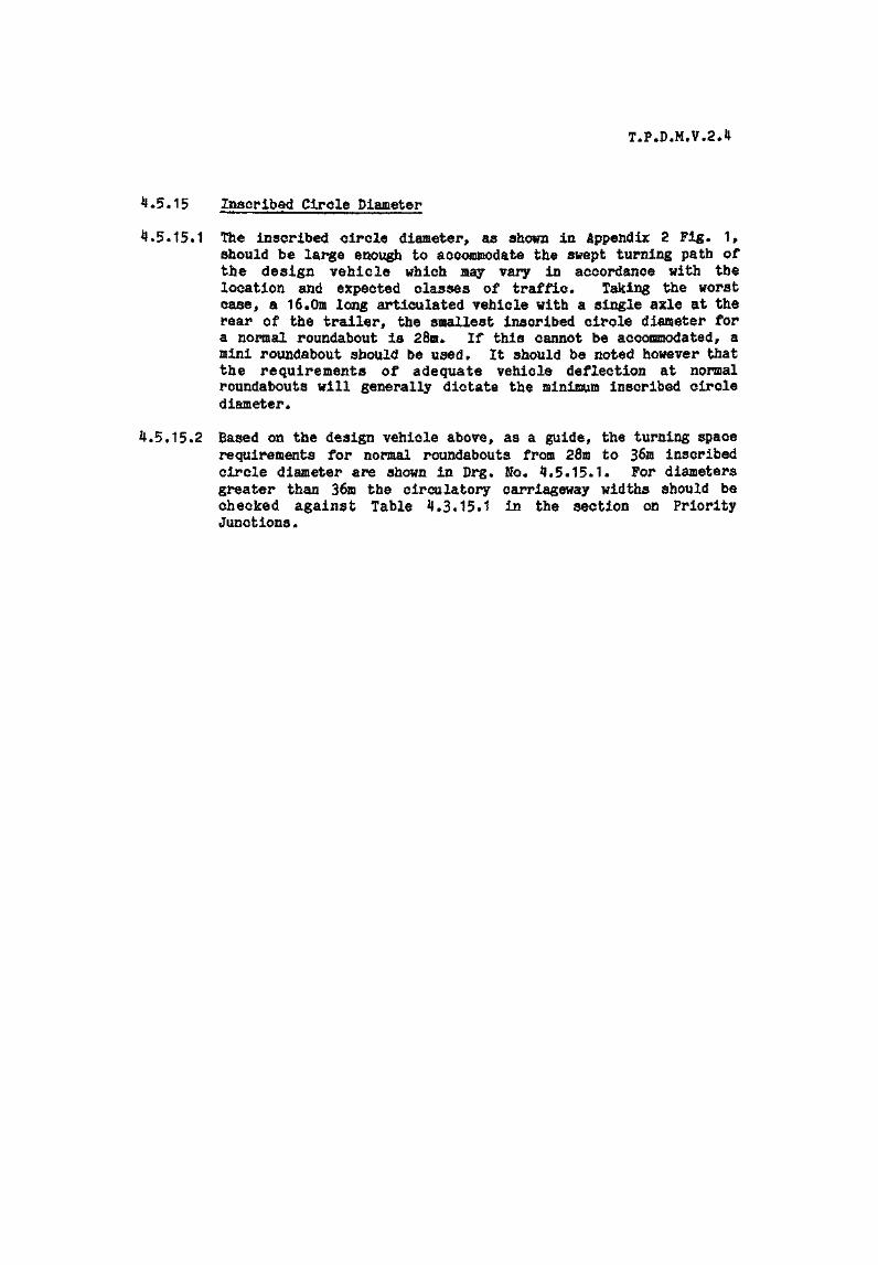
T.P.D.M.V.2.4
4*5.15 Inscribed Circle Diameter
4,5.15.1 The inscribed circle diameter, as shown in Appendix 2 Pig. 1,should be large enough to accommodate the swept turning path ofthe design vehicle which may vary in accordance with thelocation and expected classes of traffic. Taking the worstcase, a 16.0m long articulated vehicle with a single axle at therear of the trailer, the smallest inscribed circle diameter fora normal roundabout is 28m. If this cannot be accommodated, amini roundabout should be used. It should be noted however thatthe requirements of adequate vehicle deflection at normalroundabouts will generally dictate the minimum inscribed circlediameter.
4*5.15*2 Based on the design vehicle above, as a guide, the turning spacerequirements for normal roundabouts from 28m to 36m inscribedcircle diameter are shown in Drg, No. 4.5.15.1. For diametersgreater than 36m the circulatory carriageway widths should bechecked against Table 4.3*15.1 in the section on PriorityJunctions.

T.P.O.M.V. 2.4.
CENTRAL ISLAND/
\
IN THESE CASES NO ENTRYDEFLECTION ISLANDS SHOULDPROTRUDE WITHIN THE ICO
1ffl CLEARANCEHINIMUH
INSCRIBEDCIRCLE DIAMETER
CENTRAL ISLANDDIAMETER { m )
4.0 :
6 0
8 . 0
10 0
12 0
14. 0
16 0
18 0
R1
. (m)
3.0
4.0
5.0
6.0
7.0
8 0
9.0
10.0
R2
(m )
13.0
13.4
13 9
14 4
15 0
1 5 . 6
16. 3
17 0
MINIMUM I C O(m)
28. 0
28 8
2 9 - §
30-83 2 - 0
3 3 - 2
34 636.0
DIAGRAM
4.5.15.1.
TURNING WIDTHS REQUIRED FOR SMALLERNORMAL ROUNDABOUTS
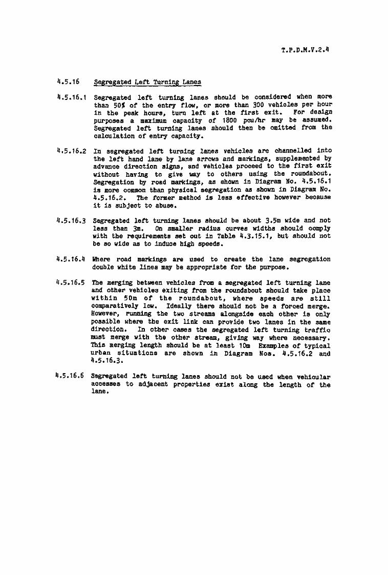
T.P.D.M.V.2.4
4.5.16 Segregated Left Turning Lanes
4.5*16*1 Segregated left turning lanes should be considered when morethan 50% of the entry flow, or more than 300 vehicles per hourin the peak hours, turn left at the first exit. For designpurposes a maximum capacity of 1800 pcu/hr may be assumed.Segregated left turning lanes should then be omitted from thecalculation of entry capacity.
4.5.16.2 In segregated left turning lanes vehicles are channelled intothe left hand lane by lane arrows and markings, supplemented byadvance direction signs, and vehicles proceed to the first exitwithout having to give way to others using the roundabout.Segregation by road markings, as shown in Diagram No. 4.5*16.1is more common than physical segregation as shown in Diagram No.4.5*16.2. The former method is less effective however becauseit is subject to abuse.
4.5.16.3 Segregated left turning lanes should be about 3.5m wide and notless than 3m. On smaller radius curves widths should complywith the requirements set out in Table 4.3.15.1, but should notbe so wide as to induce high speeds,
4.5.16*4 Where road markings are used to create the lane segregationdouble white lines may be appropriate for the purpose.
4.5.16.5 The merging between vehicles from a segregated left turning laneand other vehicles exiting from the roundabout should take placewithin 50m of the roundabout, where speeds are stillcomparatively low. Ideally there should not be a forced merge*However, running the two streams alongside each other is onlypossible where the exit link can provide two lanes in the samedirection. In other cases the segregated left turning trafficmust merge with the other stream, giving way where necessary.This merging length should be at least 10m Examples of typicalurban situations are shown in Diagram Nos. 4.5.16.2 and4.5.16.3.
4.5.16*6 Segregated left turning lanes should not be used when vehicularaccesses to adjacent properties exist along the length of thelane.

T P O M.V? 4
A SEGREGATED LEFT TURNING LANE USING ROAD MARKINGS
DIAGRAM 4.5.16.1.

Note:-
This is not a recommendation but merely a sosrifivexampte of the compromise needeTh Durban Ration« was not possible to achieve desirable valu« ofdeflector, because of adjacent developmentapproaches have speed limits.
PHYSICALLY SE6
DIAGRAM

T . P O . M . V . 2 . 4 .
GIVE WAY SIGN
VERY CLEAR INDICATIONMUST BE GIVEN TOSEGREGATED LEFT TURNINGLANE LANE TRAFFIC
REGARDING THE NEED TOGIVE WAY TO TRAFFIC
LEAVING THE ROUNDABOUT
NOTE:
THIS IS NOT A RECOMMENDATION , BUTMERELY A SPECIFIC EXAMPLE SHOWINGTHE MODIFICATION OF A PREVIOUS MAJOR/
MINOR JUNCTION WHERE IT WAS NOT
POSSIBLE (BECAUSE OF SITE CONSTRAINTS)
TO PROVIDE DESIRABLE ENTRY DEFLECTIONON ONE APPROACH
THERE ARE HOWEVER SPEED LIMITS ON
THE APPROACHES
DIAGRAM 4.5.16.3.
'STRAIGHT THROUGH' SEGREGATED LEFT
TURNING LANE AT 3-w ROUNDABOUT
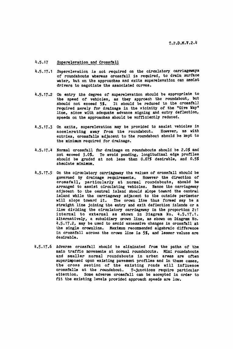
T.P.D.M.V.2.4
4.5.17 Superelevation and Cross fa 11
4.5.17-1 Superelevation is not required on the circulatory carriagewaysof roundabouts whereas crossfall is required, to drain surfacewater, but on the approaches and exits superelevation can assistdrivers to negotiate the associated curves.
4.5*17*2 On entry the degree of superelevation should be appropriate tothe speed of vehicles, as they approach the roundabout, butshould not exceed 5%. It should be reduced to the crossfallrequired merely for drainage in the vicinity of the "Give Wayttline, since with adequate advance signing and entry deflection,speeds on the approaches should be sufficiently reduced.
4.5.17.3 On exits, superelevation may be provided to assist vehicles inaccelerating away from the roundabout* However, as withentries, crossfalls adjacent to the roundabout should be kept tothe minimum required for drainage.
4*5.17*4 Normal crossfall for drainage on roundabouts should be 2.QJ5 andnot exceed 3.0J. To avoid ponding, longitudinal edge profilesshould be graded at not less than 0.67JJ desirable, and 0.5Jfabsolute minimum.
4.5.17*5 On the circulatory carriageway the values of crossfall should begoverned by drainage requirements. However the direction ofcrossfall, particularly at normal roundabouts, should bearranged to assist circulating vehicles. Hence the carriagewayadjacent to the central island should slope toward the centralisland while the carriageway adjacent to the outside perimeterwill slope toward it. The crown line thus formed may be astraight line joining the entry and exit deflection islands or aline dividing the circulatory carriageway in the proportion 2:1internal to external as shown in Diagram No. 4.5.17.1.Alternatively, a subsidiary crown line, as shown on Diagram No.4.5*17.2, may be used to avoid excessive changes in crossfall atthe single crownline. Maximum recommended algebraic differencein crossfall across the crown line is 5$, and lesser values aredesirable.
4.5*17*6 Adverse crossfall should be eliminated from the paths of themain traffic movements at normal roundabouts* Mini roundaboutsand smaller normal roundabouts in urban areas are oftensuperimposed upon existing pavement profiles and in these cases,the cross section of the existing roads will influencecrossfalls at the roundabout. T-junctions require particularattention. Some adverse crossfall can be accepted in order tofit the existing levels provided approach speeds are low.
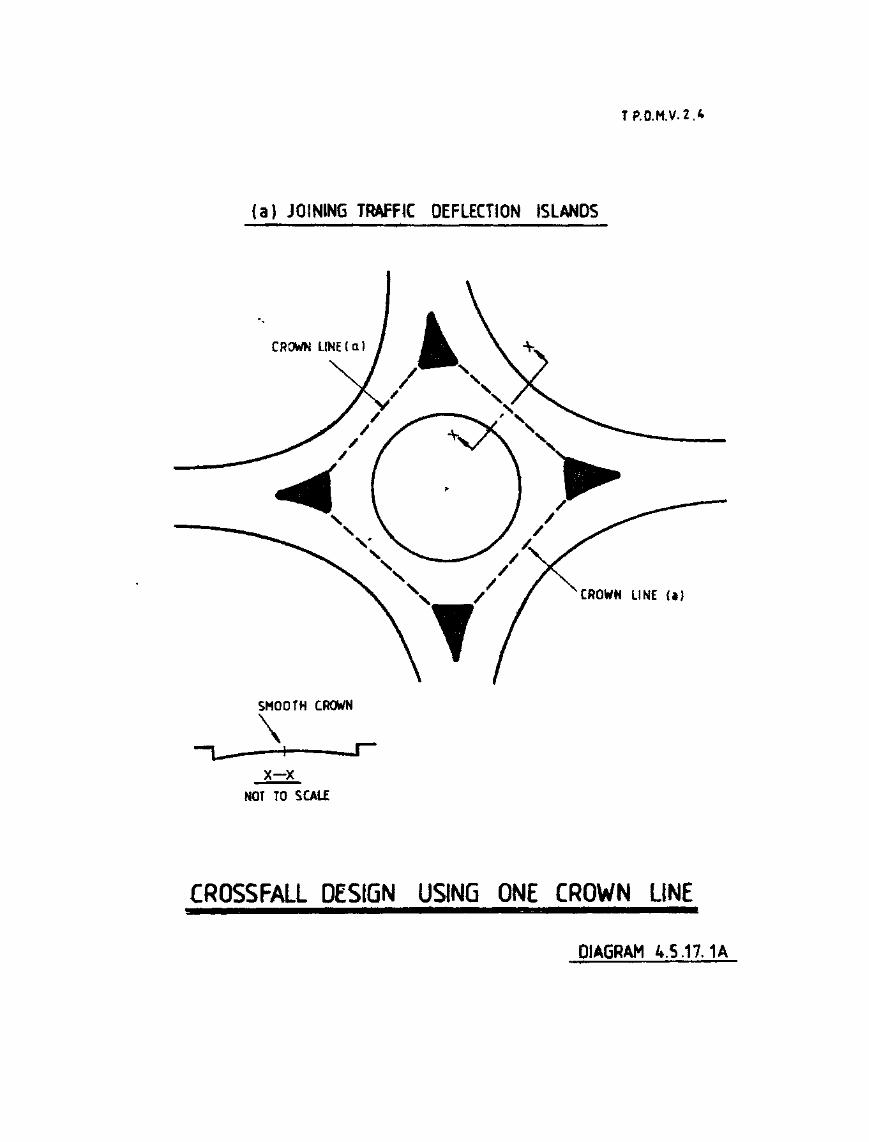
TP.O.M.V.2.4
(a) JOINING TRAFFIC DEFLECTION ISLANDS
CROWN LINE (a)
SMOOTH CROWN
\X—X
NOT TO SCALE
CROSSFALL DESIGN USING ONE CROWN LINE
DIAGRAM 4.5.17.1 A

(b) DIVIDING CIRCULATORY CARRIAGEWAY 2:1
CROWN L I N E i b )
SMOOTH CROWN
\X—X
NOT TO SCALE DIAGRAM 4.5.17.1B
CROSSFALL DESIGN USING ONE CROWN LINE

T.P.O.M.V.2,4
CROWN LINE
SUBSIDIARY CROWN LINE
x-xNOT TO SCALE
CROSSFALL DESIGN USING TWO CROWN LINES
DIAGRAM 4.5.17.2

T.P.DJM.V.2.4
4.5.18 Signing and Lighting
4.5.18.1 Design of signing and lighting should form an early part of theoverall design process.
4.5.18*2 "Give Way" signs should be erected in association with the "GiveWay" dotted lines at all roundabout approaches. The "Give Way"triangular marking is not required unless particular emphasis isrequired.
4.5.18.3 On the central island of normal roundabouts "Turn Left" signsand "Chevron" signs should be erected opposite each approach.These may be moved further to the left to emphasise the angle ofturn and thereby encourage lower traffic speeds. At miniroundabouts the central dome or circular marking should be freeof all signs, lighting columns or other street furniture.
4.5*18.4 The "Roundabout Ahead" sign should be used on all approaches andmay be supplemented with a "Reduce Speed Now Plate", where highapproach speeds are anticipated. "Count-down" markers and"Yellow Bar11 markings are also effective in reducing speeds.
4.5.18.5 A map type advanced direction sign should be used on theapproaches of all roundabouts on major routes and can also provebeneficial on minor routes where the roundabout is an irregularshape.
4.5.18.6 Road markings should channelise traffic and where appropriateindicate a dedicated lane. Lane dedication should not be usedhowever where entries are less than three lanes wide. Where anyparticular lane is dedicated the other lanes should also havearrow markings. Lane dedication arrows and markings on thecirculatory carriageway are not recommended.
4.5*18.7 The provision of road lighting at roundabouts should be regardedas an essential safety requirement. When an existing roundaboutjunction is being modified, the lighting should be checked forsuitability with the new road arrangement.
4.5.18.8 For detailed information on signing Volume 3 of this Manualshould be consulted.

4.5.19 Landscaping
4.5*19*1 Apart from the amenity benefits, the landscape treatment ofroundabouts can have practical advantages from a trafficengineering point of view- By earth modelling, perhaps inconjunction with planting, the presence of the roundabout can bemade more obvious to approaching traffic. The screening oftraffic on the opposite side of the roundabout to the point ofentry can, without restricting necessary visibility, avoiddistraction and confusion caused by traffic movements of noconcern to a driver. Planting can provide a positive backgroundto chevron signs and direction signs on the central island whilevisually uniting the various vertical features and reducing anyappearance of clutter*
4.5.19.2 Generally the planting of roundabout islands less than 10m indiameter is inappropriate as the need to provide drivervisibility leaves only a small central area available. Such arestricted area of planting is out of scale with the roundaboutas a whole, and becomes an incongruous wblobn.
T.P.B.M.7.2.4
4.6 Grade Separated Junctions
4.6.1 Introduction
4.6.1.1 Grade separated junctions occur where some or all of theintersecting roads pass each other at different levels and someor all of the turning movements are catered for by rampsconnecting the two levels.
4.6.1.2 Compared with other junction types, grade separated junctionsoffer increased capacity, less vehicular delay, fewer accidentsand reduced operating costs* These benefits are offset by thehigh construction costs and usually increased land take. Landtake, which is of prime importance in the vast majority oflocations in Hong Kong, can however be minimised with prudentdesign. Junction layouts should be as compact as possiblewithin the limitations imposed by the minimum geometricstandards discussed in subsequent paragraphs.
4.6.1.3 The layouts and standards recommended in this section are mostappropriate to trunk road and primary distributor junctionswhere most grade separated layouts may be expected.

T.P.D.M.V«2*4
4.6.2 Types of Grade Separated Junction
4.6*2.1 There are very many types of grade separated junction. Thechoice of a particular type in any situation will depend uponsuch factors as the relative status of the intersecting roads,the through route and turning traffic volumes and the siteconstraints. Some of the more common types of junction areshown on Diagram No. 4.6.2.1 and discussed below. The designershould however consider variations on these types or totallydifferent layouts to best suit the particular conditions.
4.6.2.2 The Trumpet Interchange is a common layout at a T or Y junctionand utilises a single bridge structure carrying the minor roadabove the major road. It is most suitable where the loopmovement is small and additional structures may be required toprovide a better alignment for this movement where higher flowsare involved.
4.6.2.3 The Diamond Interchange is the simplest type of 4-way junctionconsisting of a single bridge and four one way ramps. It isparticularly suitable in the Territory as it can be locatedwithin a relatively narrow land area, requiring little extrawidth beyond that required for the major road itself. Linkedtraffic signals may be required at the junctions between theslip roads and the minor road.
4.6.2.4 The Roundabout Interchange requires two bridge structures andrequires more land than the Diamond but has higher free flowcapacity. It is hence more suitable when minor road/rampconflicts are higher.
4.6.2.5 The Elevated Major Route includes those junctions where themajor route is carried on bridge structure over the minor route*A basic principle in the design of grade separated interchangesis that the minor route should be carried above the major route.This is normally the more economical arrangement and has thedistinct advantage of providing accelerating traffic with a downgradient and decelerating traffic with an up gradient. In theexisting urban areas of the Territory however it has frequentlybeen necessary to provide new major routes above the existingroad network. This has lead to numerous junctions with anelevated major route. The junction between the ramps and theminor road may be controlled by means of a roundabout or bysignals.
4.6.2.6 The Cloverleaf Interchange is the only single structure 4~wayinterchange having no terminal right turns at-grade. Inter-nationally it is perhaps the most common form of interchange,but its excessive use of land does not recommend it for adoptionin the Territory. The other major drawback with this type oflayout is the short weaving length between entry and exit ramps.

T.P.D.M.7.2.4
4.6.2.7 The Partial Cloverleaf Interchange is useful for accommodating ajunction within a space constrained by existing development.The quadrant in which the ramps are located can be varied tosuit the site restrictions.
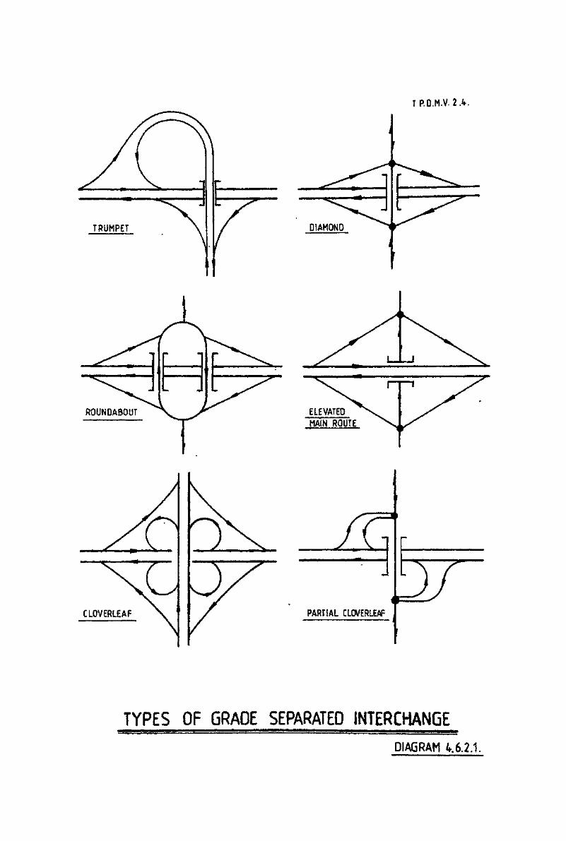
T P . O . M . V . 2 A .
CLOVERLEAF PARTIAL CLOVERL£AF
TYPES OF GRADE SEPARATED INTERCHANGE
DIAGRAM t.6.2.1.

4*6*3 Siting of Grade Separated Junctions
4.6*3.1 Interchanges should not be sited where approach roads have longsteep gradients which will materially slow heavy vehicles andcause them to bunch* For the same reason interchanges shouldalso be avoided at the crest of hills where additionally,signing may be a problem as drivers atteapt to read signssilhouetted against the skyline*
4*6*3.2 The siting of one interchange with respect to the adjacent oneswill be governed by the requirements of minimum merging, weavingand diverging lengths as discussed in subsequent paragraphs*
4*6*3*3 In urban areas interchange location should take account of theeffect of its elevated structures on adjacent development* Toprotect the privacy of occupants, it is recommended thatelevated structures should not be constructed closer than 20m toresidential buildings. The nuisance caused by fumes, noise andvisual intrusion should also be taken into account andminimised* For the operation of fire service appliances aminimum of 6m is required between elevated structures and alladjacent buildings*

T.P.D.M.V.2.4
Capacity of Grade Separated Junctions
The capacity of a grade separated interchange is governed by thecapacity of the individual merging, diverging and weavingsections within that interchange. Based on limiting values ofmain line flow, link flow and merging, diverging or weavingcapacities, standard layouts are recommended which can cater fordifferent combinations of major and minor route design flows.The method by which design flows are derived, and then appliedto produce a layout with adequate capacity, is coveredseparately for merging lanes, diverging lanes and weavingsections under those respective headings, in subsequentparagraphs.

4,6.5 General Layout Requirements
4.6.5.1 Interchanges should be designed to cater primarily for the majorflows, with the through movements maintaining the design speedselected for the through route between junctions. Geometricparameters relating to turning movements should reflect themagnitude of design flow for that movement.
4.6.5.2 Generous curvature, in for example 270° loops, can be wastefulin land and capital costs and will not necessarily lead to lowoperating costs, for the extra distance travelled at high speedmight outweigh slower speeds on a shorter tighter loop.
4.6*5*3 Decision points should be separated as much as possible and thenumber of decision points in any one sequence kept to a minimum.
4*6.5.4 Consideration should be given to bus routes operating on themajor road to identify the need for bus stopping facilitieswithin or adjacent to the interchange.

4.6.6 Visibility
4.6.6*1 Visibility distances are related to the design speed of the roadas shown in Table 4,6*6.1*
Table 4.6.6.1
Visibility Distances at Grade Separated Interchanges
Design Speed Desirable Minimum Absolute Minimum(km/h) (m) (m)
120 300 225
100 225 165
85 165 125
70 125 95
60 95 70
50 70 50
40 50 40
30 40 30
4*6*6.2 Forward visibility at the merge or diverge should be similar tothat on the mainline, but once on the link road the visibilitystandards applicable to that route apply,
4.6*6.3 Sideways visibility is particularly important at the mergesection and this is provided by a long merge nose which is shownon the merging layouts as 60m, which should be considered asminimum*
4.6.6*4 The minimum length of diverge nose is 40m. The verticalalignment of the diverge link beyond the nose should be readilyvisible to traffic in the diverging lane so that drivers canassess the speed value in advance.

T.P.D.M.V.2.4
^6*7 Slip Roads
4.6.7*1 The design speed on the slip road will generally be lower thanthe design speed on the main line and hence the need foracceleration and deceleration lanes* The discrepancy in speedshowever should not be so great as to hinder the safe andefficient transfer between the two* Table 4.6.7*1 shows theminimum slip road design speed for various main line designspeeds and the corresponding slip road minimum curve radii.
Table 4.6.7.1
Minimum Slip Road Design Speed and Curve Radii
Main Line Slip Road Slip Road Curve RadiiDesign Speed Design Speed Desirable Minimum Absolute Minimum
(km/h) (km/h) (m) (a)
120 80 230 115
100 60 125 63
85 50 88 44
70 40 60 35
60 30 40 30
50 25 30 25
4.6.7.2 Slip roads may be single lane or two lane depending on thetraffic volume. In both cases the slip road width will vary inrelation to the curve radii*
4.6.7.3 The overall width of any ramp or slip road will be determined bythe effective carriageway width plus the width required for theparapets on either side.
4.6.7.4 The effective carriageway width is that occurring between theinside foot of the parapet, or any kerb face if this isprovided, on either side of the slip road or ramp, as shown fora single lane slip road in Diagram 4.6.7*1.
4.6.7.5 The effective carriageway width shall include marginal strips ofappropriate width in accordance with Diagram 4*6.7*1 for singlelane slip roads and paragraph 4.6.7-12 for two lane slip roads.The marginal strips must be delineated by a 100mm continuousedge line marking, as illustrated in Diagram 4.6.7.1.
4.6.7.6 The standard effective carriageway width for single lane rampsor slip roads is 5«2m, subject to paragraph 4.6.7.11.
4.6.7.7 Effective carriageway widths other than the standard effectivecarriageway width should be considered in accordance with thefollowing guidelines :-

T.P.D.M.V.2.4(A1/92)
(i) Where the combined, Heavy Goods Vehicle, Medium GoodsVehicle, Bus and Coach traffic flow is predicted tobe less than 5$ of the design year AADT flow, subjectto paragraphs 4*6.7*8, 4.6.7.9 and 4.6.7.11* theeffective carriageway width may be reduced to 4.3m;or
Cii) Where the combined, Heavy Goods Vehicle, Medium GoodsVehicle, Bus and coach traffic flow is predicted tobe greater than 10J{ of the design year AADT flow,subject to paragraph 4.6.7.11, the effectivecarriageway width shall be increased to 6m, exceptthat where very high costs may arise, the standardeffective carriageway width of 5*2m may be provided.However it will be necessary in this case tosubstantiate the savings that would be obtained, andprovide details of the indications of adopting 5.2mrather than 6m.
4.6*7.8 It should be noted that the 5.2m width will allow a goodsvehicle to pass a stationary car, but in the event of a goodsvehicle or bus breaking down it is unlikely that another goodsvehicle or bus would be able to pass the broken down vehicle.Similarly, whilst the JJ.3m width will allow a car to passanother stationary car, it is unlikely that a goods vehicle orbus could pass the same stationary car. Therefore whencontemplating the use of an effective carriageway width lessthan 6m, consideration should be given as to whether on theparticular single lane ramp or slip road there is for any reasonlikely to be a higher breakdown incidence than normal, theeffects of which might be worsened if a too narrow width wasadopted. Consideration must also be given to the availabilityof alternative routes which could be used to by-pass theobstruction. The Public Transport Planning Division of theTransport Department should be consulted to ascertain whetherthere is any likelihood of a bus route being required at anytime in the future, which might be prejudiced if an inadequateoperational width was provided.
4.6.7.9 Where single lane ramps or slip roads are greater than 50m inlength the effective carriageway width should not normally beless than 5»2m»
4.6.7.10 Where single lane ramps or slip roads are greater than 100m inlength the Traffic Control and Surveillance Division of theTransport Department should be consulted to ascertain whethersurveillance measures need to be included in the scheme.
4.6.7*11 To ensure adequate clearance between any vehicle and theparapets, and to maintain the passing requirements mentioned inparagraph 4.6.7.8 the effective carriageway widths should bewidened on curves in accordance with Table 4.6*7.2.

T.P.D.M.V.2.4
4*6.7.12 The width of two lane slip roads is based on the need tomaintain two lanes of moving traffic whilst providing sufficienthorizontal clearance between vehicle and parapet. The effectivecarriageway width should be 8.75m or 7«75m comprising a 6.75mcarriageway and two marginal strips which should each be 1m wideon Rural Trunk Roads and 500mm in width on other roads. As withsingle lane slip roads the effective width should be maintainedthrough curves by appropriate widening as shown in Table4.6*7*2. The desirable minimum standard in this Table is basedon the requirements of a 16.0m articulated vehicle. Absoluteminimum values are also given but these should not normally beused and in any case not used on bus routes and in situationswith more than the minimum volumes of medium and heavy goodsvehicles. Both desirable minimum and absolute minimum valuesinclude two marginal strips each one metre wide and theeffective width should be correspondingly reduced if 500mmmarginal strips are used,
4.6.7.13 For both two lane and single lane slip roads, where widening isprovided through curves the marginal strips should be maintainedat the same width as those on the approach to the curve.
Table 4.6.7.2
Minimum Effective Carriageway Widths on Slip HoadsRelated to Inside Radius of Curve (m)
Single Lane Slips{Including Marginal Strips)
Two Lane Slips(Including Two 1mMarginal Strips)
InsideRadiusof Curve(m)
15202530405075100150
Straight
6m EffectiveCarriageway
Width
Width on Curve(m)
n/an/a8.27.87.26.96.56.366
5.2m StandardEffectiveCarriageway
Width
Width on Curve(m)
n/an/a6.86.45.85.65.45.25.25.2
4.3m EffectiveCarriageway
Width
Width on Curve(m)
7.16.25.75.34.74.34.34.34.34.3
DesirableMinimum(m)
n/an/a12.912.311.310.710.09.69.38.75
AbsoluteMinimum(m)
n/an/a10.510.29.99.79.49.39.08.5
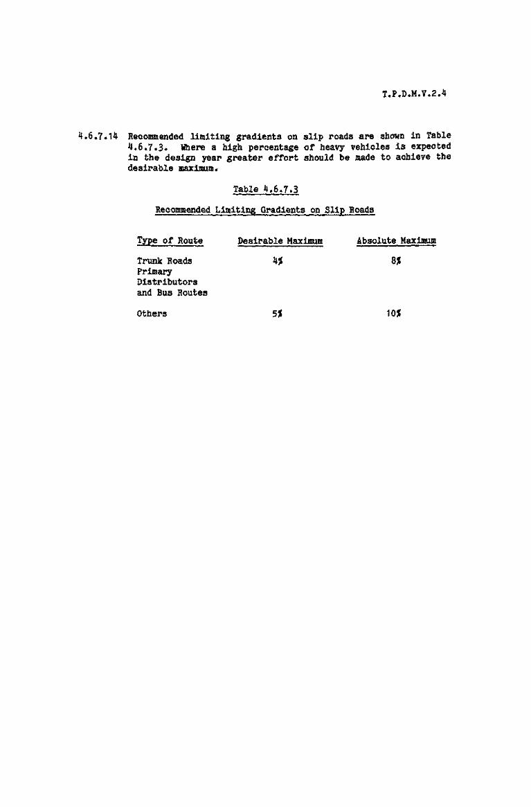
Recommended limiting gradients on slip roads are shown in Table4,6.7.3* Where a high percentage of heavy vehicles is expectedin the design year greater effort should be made to achieve thedesirable maximum,
Table 4.6.7*3
RecommendedLimiting Gradients on Slip Roads
Type of Route Desirable Maximum Absolute Maximum
Trunk Roads 4j£ B%PrimaryDistributorsand Bus Routes
Others 5%

T.P.O.M.V.2.4.
FIG. A
EFFECTIVE CARRIAQEWSlT WIDTH
100 EDGE LINE11109)
FIG. B
STANDARD EFFECTIVECARRIAGEWAY WIDTH
100 EDGE LINE(1109)
EFFECTIVE CARRIAGEWAY WIDTH
FIG. C100 EDGE LINE
(1109)
EFFECTIVE CARRIAGEWAY WIDTH
EFFECTIVE CARRIAGEWAY WIDTHS OF
SINGLE LANE RAMPS AND SUP ROADS
DIAGRAM 4.6.7.1.

T.P.D.M.V.2.4
4.6.8 Merging Lanes
4.6.8.1 The recommended standards for merging lanes are based on a mainline operating speed of 80 km/h, which seems the mostappropriate for those roads in the Territory which will utilisegrade separated junctions. The recommended layouts may beadopted for lower or higher speeds however with suitableadjustment to the proposed standards.
4.6.8.2 In normal circumstances the direct entry, i.e. where the merginglane joins the main road via a straight taper, is preferred.Situations will occur however where a more generous layout,including a parallel merging lane plus taper, will be justifiedby difficult site conditions as discussed in paragraph 4.6.8.5.Both layouts are depicted in Diagram No. 4.6.8*1.
4.6.8.3 For the direct entry merging lane a taper of 1:30 isrecommended. For single lane entries however this should beincreased to 1:40 wherever possible.
4.6.8.4 The length of merge nose should be a minimum of 60m to provideadequate sideways visibility for merging traffic.
4.6.8.5 As stated in paragraph 4.6,8.2 an additional length of parallelmerging lane may be required in the following types ofconditions :-
(i) Where the main line is on a significant left handcurve. In this case visibility is limited and thedirect entry is not so effective as the angle ofconvergence is too great. By providing a length ofparallel lane, drivers are able to observeconditions on the main line by using their drivingmirrors rather than turning their heads.
(ii) Where the main line and hence the merging lane is ona steep upgrade. Here the problem is one ofmatching speeds and a greater distance is requiredby merging vehicles in which to accelerate*
(iii) Where the main line is on a steep down gradientthere may also be problems associated with the highspeed of vehicles in the near side lane.
In these situations an additional merging lane 3-7m wide and aminimum of 100m long with a 70m taper should be provided.
4.6.8.6 At higher entry flows two merging lanes may be required and theresulting layout may be of the direct or shadow island type.Both types of layout are depicted; Diagram No. 4.6.8.2illustrating the situation with a consistent number of lanes' onthe main line, and Diagram Bo. 4.6.8.3 showing the case wherethere is a pick up of one lane after the junction.

T.P.D.M.V.2.4
4.6.8.7 The method of deciding on the appropriate merging lane layout,which will provide the required capacity to cater for the designflows, is described in the following paragraphs. It should beremembered however that the layout thus recommended may needadjusting through outside influences such as a policy decisionto provide the same number of lanes throughout the whole mainline route, for example.
4.6.8.8 Design year flows in vehicles per hour should be obtained forthe main line and the entry link* The worst combination ofthese flows, allowing for possible different timing of peaks, isthen used as a base. The base flows are then adjusted for non-standard combinations of traffic composition and gradient asindicated in Table 4.6.8.1. The gradient should be measuredover a one kilometre section of the main line, centred on themerge nose.
Table 4.6.8.1
Percentage Corrections to Predicted Flow forNon-standard Composition and Gradient
Percentage of Heavy Vehicles on Linkor Main Line - Being Considered
Gradient on Main Line 5 J J ) 1 5 2 0 2 5 3 £ 3 5 . 4 £
Downhill, Level or 1$ Up - 8 - 4 0 4 - 4 4 - 8 +12 +16 +201 5 5 - 2 $ Uphill + 2 + 6 +10 +14 +18 +22 +26 +302% - 3% Uphill +12 +16 +20 +24 +28 +32 +36 +40
4.6.8*9 The design year flows in v.p.h., adjusted as above, are thenplotted on Diagram No. 4.6.8.5 to identify a flow region, whichis indicated alphabetically.
4.6.8.10 Having identified the flow region to which the adjusted designyear flows correspond, Table 4.6.8.2 should be consulted to findout which merging layout types are suitable to provide therequired capacity. The layout types most likely to beappropriate are indicated with an asterisk. Where flowcombinations are close to boundaries between different flowregions, the layout types indicated for the adjacent flow regionshould also be considered.

T.P.D.M.V.2.4
Table 4.6.8.2
Type of Merging Layout Appropriate to Flow Region
Number ( Upstream Main Lineof ( Link
Lanes { Downstream Main Line
1
Merging Lane Type
3 4 5 6 7
2 2 21 2 2
2 2 3
3
1
3
3
2
3
3
2
8
2 2
1 2
3 *
314
Flow
Region
A
B
C
D
E
F
G
H
I
*
*
*
*
ft
ft
ft ft ft ft
ft ft ft ft
* «
* ft
ft ft ft
ft ft ft
4*6.8.11 The merging lane types are shown in Diagram Nos. 4*6.8.1, 2, 3and 4 and the following notes on each type should also beconsidered in deciding upon the appropriate layout.
4.6*8.12 Types 1 * 4 (Diagram No. 4.6,8.1)
The direct entry is the most economical merging layout forsingle lane links* It will cater for entry flows up toapproximately 1000 v.p.h. after correction, but should only beused under favourable site conditions. Hhere the main line issituated on a left hand curve, where the main line is on agradient or where for other reasons it is necessary to providegreater definition of the merging lane, the more generousparallel type merging lane layout should be adopted.
4.6.8.13 Types 2 + 5 (Diagram No. 4.6.8.2)
The direct entry layout is suitable for the higher entry flowsnear the limit of a single lane entry but where diversegeometric conditions render a single lane entry unsuitable. Theshadow island merging layout is the more normal and preferredlayout where entry flows dictate a two lane entry and wherethere is not the need for the addition of an extra lane

T.P.D.M.V.2.4
downstream. The layout permits the right hand traffic on thelink to enter the main line early and to dissipate to form gapsfor the second merging lane* Both layouts can accommodate asingle lane link, widened to a two lane entry, whereappropriate.
4.6,8.1$ Types 3*6 (Piagram No. 4.6,8,3)
Where an extra lane is required for downstream traffic theselayouts are appropriate. The parallel entry layout gives theleft hand lane of the link free entry while the right hand laneof the link merges with the slower traffic on the main line.The shadow island entry, on the other hand, provides free entryfor the faster traffic on the link and subsequent merging of theslower traffic and is to be preferred for the higher ranges oftraffic in this category, The shadow island entry is alsopreferred on left hand curves and uphill links. In both layoutsthe slower moving traffic on the main line must eventually mergeinto the nearside lane, but there is no immediate necessary todo so,
4,6.8.15 Types 7, 8 + 9 (Piagram No, 4.6,8,4)
Types 7 * 9 are appropriate on routes where lane drop/pick upinterchanges are used. Type 8 is more appropriate in thesituation where two routes of equal status and carrying equalvolumes of traffic meet. Experience has shown that it isadvisable to present immediate weaving by the use of doublewhite lines and the length of such lines though varying withsite conditions should be at least 50m.
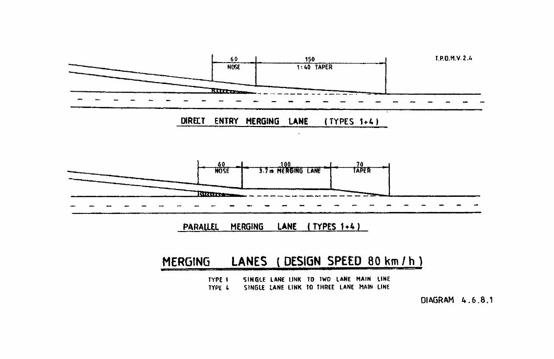
T.P.O.M.V.2.4
DIRECT ENTRY MERGING LANE (TYPES U4)
PARALLEL MERGING LANE I TYPES 1*4)
MERGING LANES ( DESIGN SPEED 8 0 k m / h )TYPE 1 SINGLE LANE LINK TO TWO LANE MAIN LINETYPE 4 SINGLE LANE LINK TO THREE LANE MAIN LINE
DIAGRAM 4.6.8.1
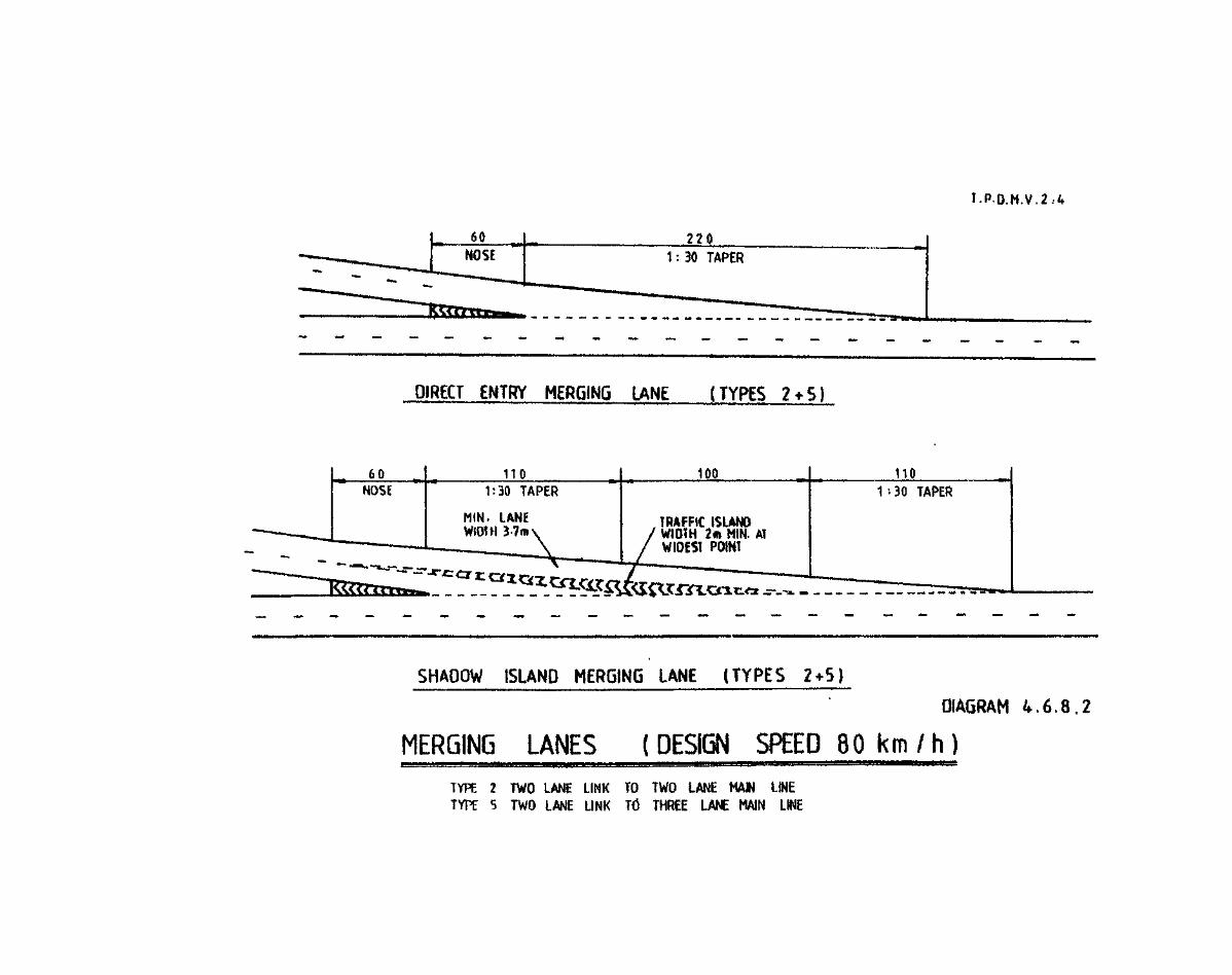
DIRECT ENTRY MERGING UN£ (TYPES 2 + 5)
TRAFFIC ISLANDWIDTH 2ffi HIM. ATWIDEST POINT
SHADOW ISLAND MERGING IANE (TYPES 2+5)
DIAGRAM 4.6.8.2
MERGING LANES ( DESIGN SPEED 80 km / h )TYPE 2 TWO LANE LINK TO TWO LANE MAW LINETYPE 5 TWO LANE LINK Td THREE LANE MAIN LINE
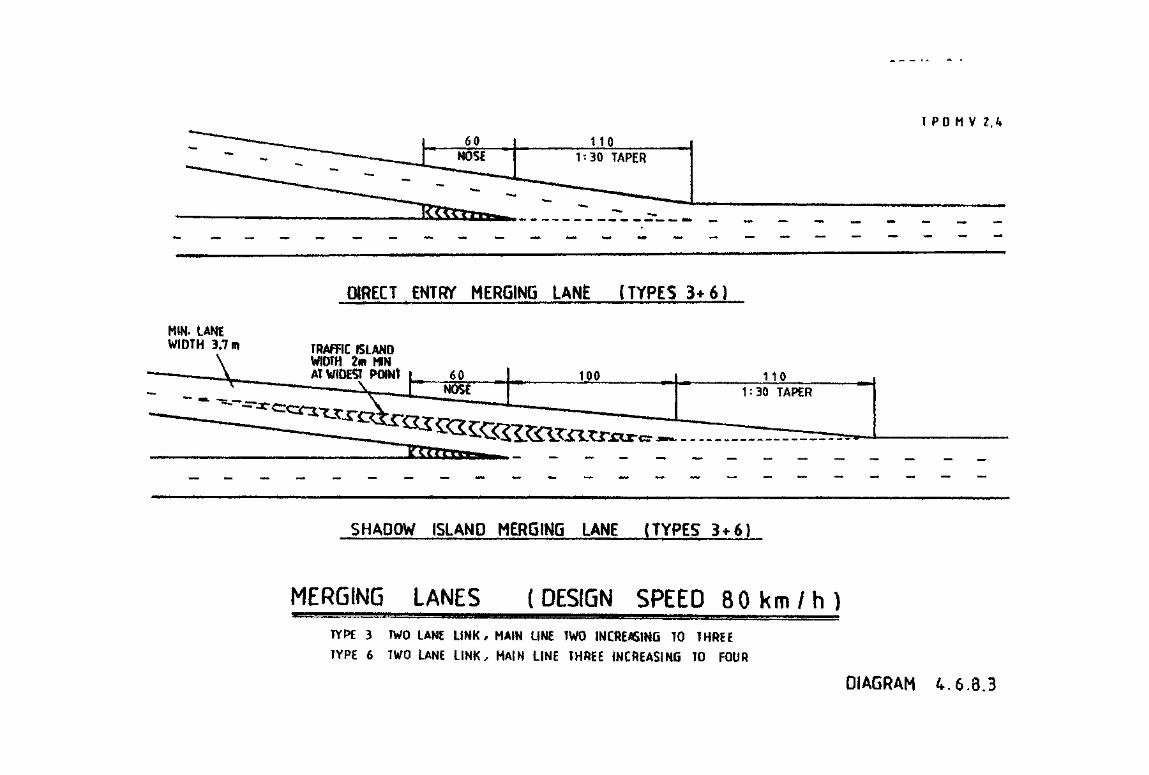
I PO M V 2.4
MIN. LANEWIDTH 3.7m
DIRECT ENTRY MERGING LANE (TYPES 3*6)
TRAFFIC ISLANDWIDTH 2m MWAT WIDEST POlNt 110
SHADOW ISLAND MERGING LANE (TYPES 3*6}
MERGING LANES (DESIGN SPEED 80 km / h )TYPE 3 TWO LANE LINK, MAIN LINE TWO INCREASING TO THREE
TYPE 6 TWO LANE LINK, MAIN LINE THREE INCREASING TO FOUR
DIAGRAM 4.6.3.3

T.P.D.H.V. 2.4
TO SUIT SITE
ADDITIONAL LANE -NO IMMEDIATE MERGING (TYPES 7 * 9 )
60NOSE
._
TO !CON!
iUIISITEDITION
ADDITIONAL LANES - NO IMMEDIATE MERGING {TYPE 8 )
MERGING LANES (DESIGN SPEED 80 k m / h )TYPE 7-SINGLE LANE LINK-MAIN LINE TWO INCREASING TO THREE
TYPE 9 - SINGtE LANE UNK - MAIN LINE THREE INCREASING TO FOUR
TYPE 8 - TWO LANE LINK-MAIN LINE TWO INCREASING TO FOURDIAGRAM 4.6.8.4
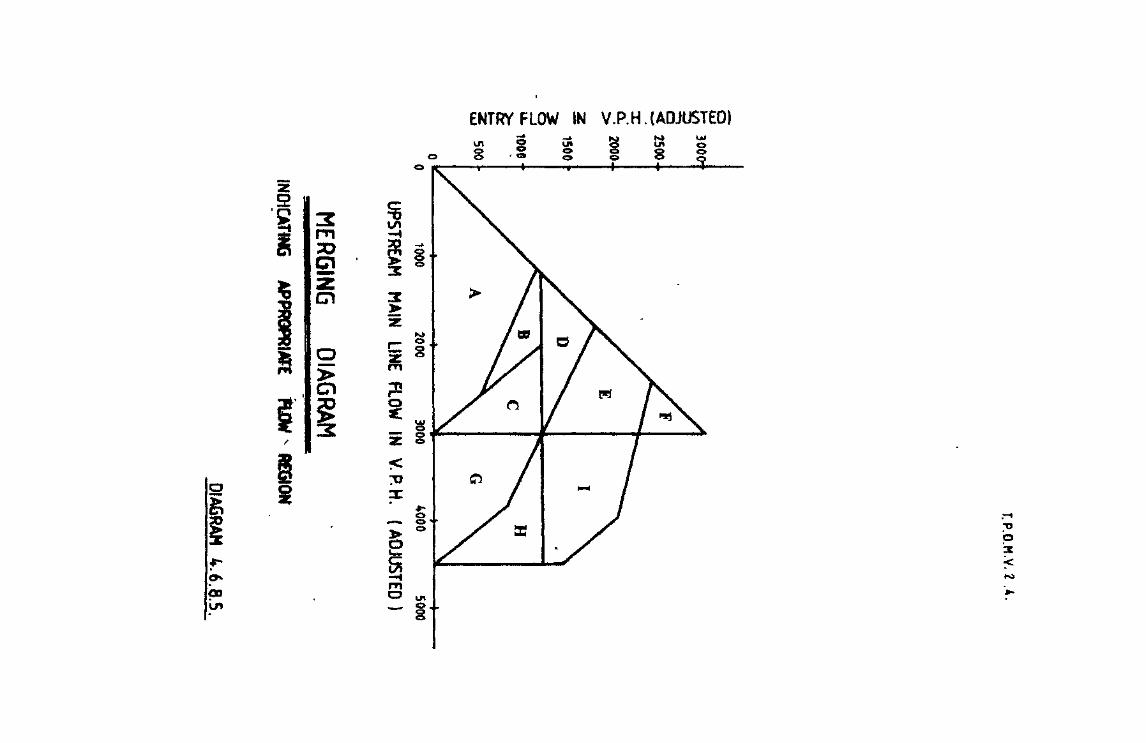

T.P.D.M.V.2.4
4.6.9 Diverging Lanes
4*6.9.1 As with merging lanes (see para, 4,6.8.1) a main line operatingspeed of 80 km/h has been used in arriving at the recommendedstandards.
4.6*9«2 The direct diverging lane, i.e. where the diverging lane exitsvia a straight taper, is to be preferred under normal siteconditions. The diverge taper shall be 1:20 except that 1:35should be adopted, to give additional space for divergingtraffic, at single lane links or at two lane links where onelane is dropped from a three lane main line.
4.6.9.3 The length of diverge nose should be a minimum of 40m.
4.6.9.4 More generous diverging layouts may be required under thefollowing adverse site conditions :-
(i) If the main line is on a significant right handcurve, a direct taper would result in a tangentialalignment and would be confusing to drivers.
(ii) If the main line is on a steep upgrade a longerdistance is needed for the diverging manoeuvre, toenable faster vehicles approaching in the outerlanes to penetrate through those heavy vehicleswhich are moving slowly in the left hand lane.
(iii) When the main line is on a steep downgrade a problemmay arise associated with the high speed of vehicleson the main line left hand lane.
In these situations an extra diverging lane 3*7m wide and atleast 100m long with a 70m taper should be provided.
4.6.9.5 To decide upon the most appropriate diverging lane layout toaccommodate design year flows, a method is employed which is thesame as that used for merging lanes. Igain it should beemphasised however that the method described in subsequentparagraphs indicates the most suitable layout for a divergeconsidered in isolation. The other junctions along the mainline route should also be considered, so that drivers may bepresented with a consistent set of layout features.
4.6.9.6 The main line and link flows should be assessed in terms ofv.p.h. in the design year and the worst combination of theseflows, taking account of different peak periods, used as a base.The base flows should then be adjusted for non standard trafficcomposition and gradient as shown in Table 4.6.8.1, Thegradient should be measured over a distance of one kilometre,centred upon the nose of the diverge lane.

T*P*D.M.V.2.4
4.6.9*7 The design flows in v.p.h., adjusted as above, should then beplotted on Diagram No* 4.6.9*1 to identify the appropriate flowregion, indicated alphabetically*
4.6.9.8 Using Table 4.6.9*1 the appropriate types of layout, suitablefor handling the flow region assessed as above, are identified.The diverging lane types indicated by an asterisk are likely toprove the most acceptable in terms of level of service. Whereflow combinations are close to boundaries between different flowregions, the layout types indicated for the adjacent flow regionshould also be considered.
Table 4.6.9*1
Type of Diverging Layout Appropriate to Flow Region
Diverging Lane Type
Number ( Upstream Main Line
of ( Link
Lanes ( Downstream Main Line
( P
( Q( a
Flow ( S
Begion { T
( U
( V
1
2
1
2
«
2 3 4
2 3 3
2 1 2
2 3 2
* ftft
ft
ft *«
*ft
5 6
3 4
2 2
3 3
« «
»
«
*
7 8
3 4
1 1
2 3
*ft
ft
ft
f
9
4
2
2
ft
ft
4.6.9-9 The diverging lane types are shown in Diagram Nos. 4.6.9.2, 3, 4and 5* In conjunction with Table 4.6.9*1 the following notes oneach layout type should be considered in deciding upon the mostappropriate layout.
4.6.9*10 Types 1 * 3 (Diagram Ko. 4.6.9.2)
The direct diverging lane is the most economical layout forsingle lane links and is appropriate up to flows ofapproximately 1000 v.p.h. after correction and where siteconditions are favourable. Where the diverge is situated on aright hand curve, or where the intersection is on a gradient,the parallel diverging lane layout is more appropriate.

4.6.9.11 Types 2 + 5 (Diagram No. 4.6.9*3)
The direct diverging lane layout is appropriate for exitingflows around the limit of the single lane exit but where siteconditions do not favour a single lane. The standard layoutwhere two exit lanes are required, and where there is no lanedrop, is shown in the parallel diverging lane layout. Theparallel diverging lane layout is particularly preferred whenthe diverge is situated on a right hand curve*
4.6.9.12 Types 4*6 (Diagram No. 4.6.9.4)
Where a lane is dropped at the intersection types 4 + 6 layoutsare appropriate. The direct diverging lane may be used infavourable site conditions, whereas the parallel type layout ismore appropriate on right hand curves.
4.6.9*13 Types 7, 8 + 9 (Diagram No. 4.6.9.5)
Types 7 and 8 are appropriate along routes with lane drop/pickup at interchanges. Type 9 may be used at the divergence of tworoutes of equal importance and carrying equal volumes oftraffic.

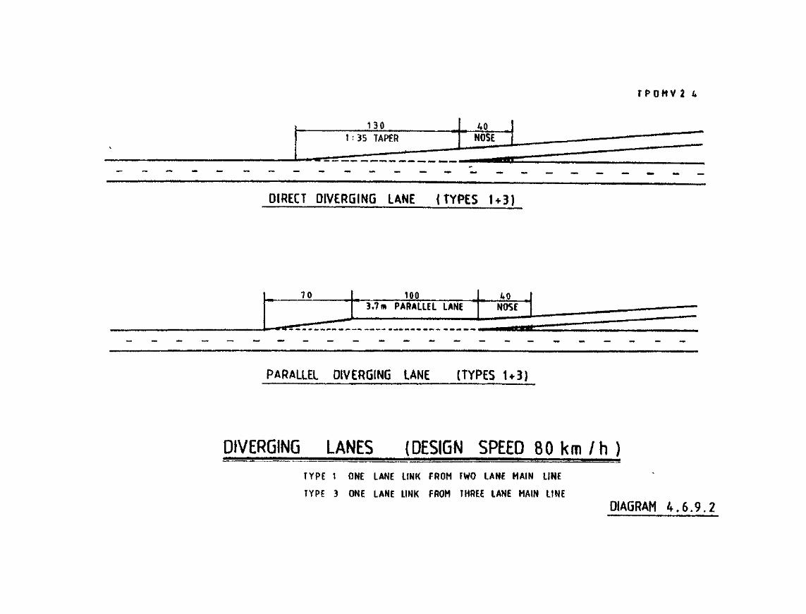

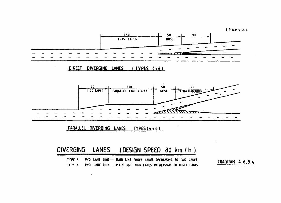
I.P.O.M.V.2.<f
DIRECT DIVERGING LANES f TYPES 4 + 6 J
PARALLEL LANE ( 3 - 7 )
PARALLEL DIVERGING LANES TYPES (4 + 6)
DIVERGING LANES (DESIGN SPEED 80 km /h )TYPE 4 TWO LANE LINK — MAIN LINE THREE LANES DECREASING TO WO LANES
TYPE 6 TWO LANE LINK — MAIN LINE FOUR LANES DECREASING TO THREE LANESDIAGRAM 4.6.9.4
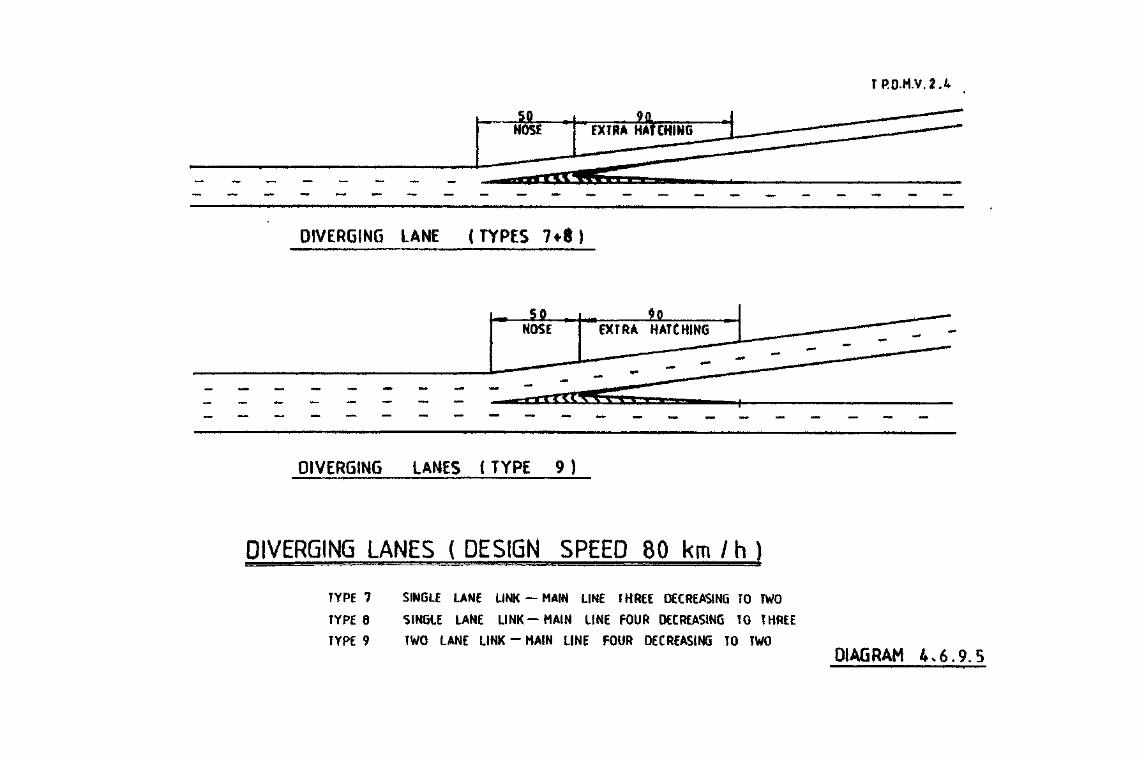
TP.O.M.V.2.4
DIVERGING LANE (TYPES 7+«)
DIVERGING LANES ( TYPE 9 )
DIVERGING LANES ( DESIGN SPEED 80 km /h )
TYPE 7 SINGLE LANE LINK — MAIN LINE THREE DECREASING TO TWO
TYPE 8 SINGLE LANE LINK—MAIN LINE FOUR DECREASING TO THREE
TYPE 9 FWO LANE LINK - MAIN LINE FOUR DECREASING TO TWO
DIAGRAM 4.6.9.5
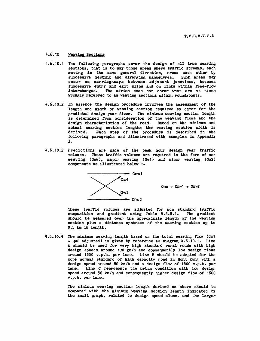
T,P*D.M*V.2*4
4.6.10 Weaving Sections
4.6*10.1 The following paragraphs cover the design of all true weavingsections, that is to say those areas where traffic streams, eachmoving in the same general direction, cross each other bysuccessive merging and diverging manoeuvres. Such areas mayoccur on carriageways between adjacent junctions, betweensuccessive entry and exit slips and on links within free-flowinterchanges. The advice does not cover what are at timeswrongly referred to as weaving sections within roundabouts*
4,6.10*2 In essence the design procedure involves the assessment of thelength and width of weaving section required to cater for thepredicted design year flows* The minimum weaving section lengthis determined from consideration of the weaving flows and thedesign characteristics of the road* Based on the minimum andactual weaving section lengths the weaving section width isderived* Each step of the procedure is described in thefollowing paragraphs and illustrated with examples in Appendix3.
4.6*10*3 Predictions are made of the peak hour design year trafficvolumes* These traffic volumes are required in the form of nonweaving (Qnw), major weaving (Qw1) and minor weaving (Qw2)components as illustrated below :-
-»*. Qnwl
;
iwt
Qnw * Qnw1 + Qnw2iw2
• Qnw 2
These traffic volumes are adjusted for non standard trafficcomposition and gradient using Table 4.6.8.1* The gradientshould be measured over the approximate length of the weavingsection plus a distance upstream of the weaving section up to0.5 km in length*
4.6*10*4 The minimum weaving length based on the total weaving flow (Qw1+ Qw2 adjusted) is given by reference to Diagram 4.6*10.1* LineA should be used for very high standard rural roads with highdesign speeds around 100 km/h and consequently low design flowsaround 1200 v.p.h. per lane. Line B should be adopted for themore normal standard of high capacity road in Hong Kong with adesign speed around 80 km/h and a design flow of 1400 v.p.h* perlane* Line C represents the urban condition with low designspeed around 50 km/h and consequently higher design flow of 1600v*p*h. per lane.
The minimum weaving section length derived as above should becompared with the minimum weaving section length indicated bythe small graph, related to design speed alone, and the larger

T.P.D.M.V.2.4
of the two values is the minimum acceptable length of weavingsection (Lmin).
4.6*10.5 The actual weaving length, particularly in connection with aweaving section between rather than within interchanges, willoften be greater than the minimum weaving length* The width ofweaving section is hence defined as a function of both theminimum and actual weaving lengths together with the predictedand design flows. The number of lanes required in the weavingsection (N) is given by the equation
U - Qnw * Qwt (2 x Lpin + Qw2D Lact D
where Qnw = total non weaving flow (adjusted) v.p.h*Qw1 s major weaving flow (adjusted) v.p.h.Qw2 s minor weaving flow (adjusted) v.p.h.D s design flow per lane in v.p.h* as described in
para. 4.6.10*4Lmin = minimum weaving length (m)Lact * actual weaving length (m)
4.6.10.6 The number of lanes within the weaving section as calculatedabove will invariably involve a fraction and a decision must betaken on whether to round up or down. In some cases it may bepossible to vary the actual weaving length in order to bring Nnearer to a whole number and hence simplify the decision* Wierethe available weaving length is fixed by outside constraints, asis normally the case, the decision to round up or down becomesmore difficult. Obviously if the fractional part is small withrelatively low weaving volumes and a low design flow, it is notunreasonable to round down. If the opposite is true, N would berounded up. Between these two extremes it is necessary toexercise judgement taking account of such factors as cost andavailability of lane for an extra lane.
4*6*10.7 It is also important to bear in mind that it is not sufficientmerely to provide the proper number of lanes; the physicalarrangement of the lanes within the weaving section must also beconsidered. Care must be taken that use of the lanes by weavingand non weaving traffic will be in proportion to their relativevolumes so that parts of the roadway do not become underusedwhile other parts become congested. The possibility of such animbalance of flows occurring may well influence the decision onwhether to round up or down, For example an outer lane added toa weaving section will generally aid only an outer non-weavingflow (particularly where 3 or more lanes are already proposed}*This is likely to be of little use if most of the traffic isweaving and the relevant outer non-weaving flow is small.
4.6*10.8 Finally it is necessary to ensure that the number of lanes inthe weaving section satisfies the requirements of the mergingand diverging sections of the inter change (s) as discussedearlier.

44-

T.P.D.M.V.2.4
4.6.11 Signing
"speeds are involved, to ensure adequate signing. On truniroaosand primary distributor roads with no at grade_Access thesigning should commence with the first A.D. sign, *kilometre in advance of the commencement of the decelerationlane. Full details of signing are given in Volume 3 of thisManual.

T.P.D.M.V.2.4
APPENDIX 1 !
Calculation of Capacity at Priority Junctions
The predictive equations discussed in paras. *J.3.6 are :-
C.B
(where Y = (1-0.0345W)}
... (1)
(2)
(3)
In each of these equations the geometric parameters represented by D, Fand F are stream-specific :-
D = Cl+0.094(w_ .-3.65)3[1+0.0009(V _ A-120)K1+0.0006(V._ .-150)3B-A rB-A IB -A
E = [1+0.094(wB_c-3.65)3[1+0.0009(VrB_c-l20)3
F = r tJ-3.65)3Cl+0.0009(V_ --120)3C— & rc-»B
The symbols represent the following :-
Q = the capacity of movement B-AB~A
q. n s the design flow of movementA—o
A~B and so on
) See Drg. No* 4.3.A.1
) Capacities and flows are
} in pcu/hour (1 HGV a 2 pou)
W a major road width
a central reserve width (kerbed
median only)
CK) See Drg. No. 4*3.A.2
fi AB~Aa lane width available to vehicle ) See Drg, No. 4.3.A.3
iwaiting in stream B-A, and so on )

T.P.D.M.V.2.4
to the ri£ht for
vehicles waiting in stream B-A
visibllity to the left for
vehicles waiting in stream B-A,
and so on
) Visibility distances for
) minor road flow is
) measured from a point 10m
) back from the give way
) line
All distances and widths are measured in metres and the ranges ofparameters in the data base were as follows :-
w = 2.05 - 4.70
V = 17.0 - 250.0r
VI = 22.0 - 250.0
WCR = 1.2 - 9.0 (kerbed central reserve only)
W r 6.4 - 20.0
The maximum values of visibility and V used in calculation andOjK
computation should be 250m and 10m respectively, even if greater values
are physically provided.
N.B.
(i) The equations for Q and Q assume separate lanes for right
and left turning minor road traffic and no simultaneous queueing for
the two movements. If simultaneous queues are sometimes present
QB-A is unaffected but the operational left turning capacity
is :~
*B-CV for < 1B-A
and B-C for > 14-A

T.P.D.M.V.2.4
If right and left turning traffic share the same lane the capacityof the combined stream is given as follows :-
QB-C.QB-AB-4C >««
where QD and Q,.. are determined using equations 1 and 2 withJo—A JD—v
the same minor stream width w for both streams and F is the
proportion of minor road traffic turning left.
(ii) At some layouts the straight through major road stream C-A becomes
blocked when there is a queue of right turning vehicles C-B.
Substantial capacity limitations will arise only In those cases
where the residual width for through traffic is less than 2,5m. In
these cases Q is given by the equation :-*
QC-A= 18°° ° - Q / Q ) P0u/h
There follows an example in the use of the priority junction
capacity equations.

T.P.D.M.V.2.*
Example of Use of Priority JunctionCapacity Equation
1* It is required to examine the feasibility of a priority junction atthe T-Junction between two S2 roads.
2. The traffic information available from the traffic model indicatesthat the design year flows at the junction would be :
600
?nnr
?«;n
Flow in p»c.u./hr.
3. A layout is prepared based on a shadow island design and the initiallayout has the following geometric parameters :
W = 7*3
= 0 (because no kerbed central median)
= 3.5
CR
wc-b
W, = 4.0b-c
w,_ = 4*0b-a
V . a 250.0 major roadC~D
V = 200 minor roadr
V, = 200 minor road

T.P.D.M.V.2.4
4» Applying the stream specific formulae to calculate the factors D, Eand F :
D = C1+0.094(4-3.65)3C1+0.0009(200-120)3C1+0.0006(200-150)J a 1.1405
E = [1+0. 094(4-3.65)3[1+0.0009(200-120)3 r 1.1073
F = [1+0.094(3.5-3.65)3El+0.0009(250-120)3 = U1013
Substituting these in the capacity formulae :
Qb-a = I'1405t527^1^x°"°-7 8l5(0.364x300+0.144x100 0.229x6004-0.520x200)3
= 293
Qb-c = 1*1073C745-0*74815(0.364x300+0*144x100)3
= 615
and
Q K = 1.1013C745-0.364x0.74815(300+100)]C—D
s 700
comparing the capacities to the design flows yields DPC values of 85%for B-A, 3315 for B-C and 29% for C-B.
The results indicated that the junction should operate satisfactorilywith queueing on the B-A stream, i.e. the right turn out of the minorroad. It would therefore be appropriate to examine the effects ofqueueing on the minor road and to critically examine the trafficpredictions for that particular flow to ensure that the true futureflow is unlikely to be higher than that initially predicted*
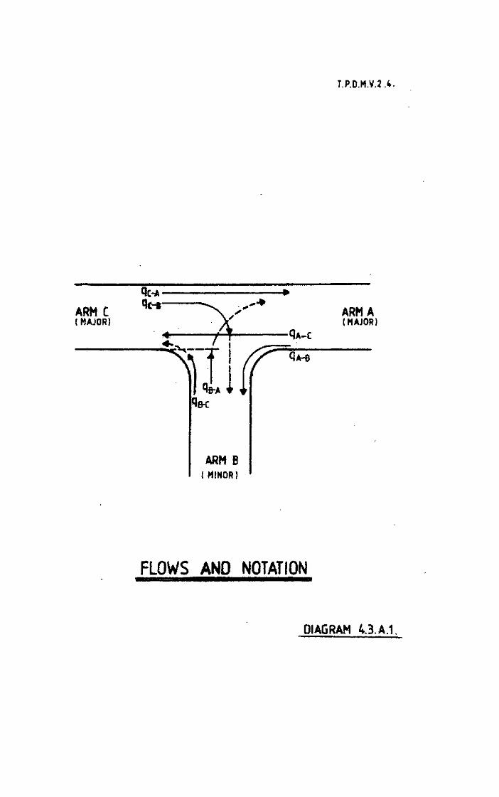
T.P.D.M.V.2.4.
ARM C( MAJOR!
ARM A(MAJOR)
AV :i QA-B
ARM B( MINOR)
FLOWS AND NOTATION
DIAGRAM 4.3.A.1.

T.P.D.M.V.2 .4
The toui parts of dmwiAg i, show the main components of major road width. They are combined to five:
(1) the 'nearside* width: Wfi
(2) the 'farside* width: Wf
Wf » Vi (Wl + W3)
(3) the total carriageway width: W
W * Wn * Wf
(4) (at dual carriageway sites with kerbed central reserve)the width of central reserve. WCR
WCR
wt
W2
W3J
W4'
W1
W2
W3|
W1 W3|
Ghost islands ITTW4
K*rt>Ml island*
DIAGRAM 4.3. A. 2 MAJOR ROAD WIDTH W AND ITS COMPONENTS

|.P.D'.M.V.2.4
14ite width I'oi itut^priucHy f^f^ w (in)
Wliere there are clear Jane markup the width i* measured directly. The average of m*|»memefit* take* *t^5m interval* over a distance of 20m upstream from the give-way point i§ used.reduced to 5m before the average is taken* Where iafie markings are unctaf (or iare used, aad the lane width calculated accofdttig to:
MAJOR ROAD
Any mwswremnt cxceedinf 5m ii»i«nt)tDN ini(t),(b),and(c)
i, to, *, d, * ** «qwa( u> tht tone widthfor
D(A6RAM 4.3.AJ LAN£ WIDTHS FOR NON PRIORiTYl STREAMS

T.P.D.M.V.2.4
APPENDIX 2
Calculation of Capacity at Roundabouts
The predictive equation for entry capacity on individual arms ofroundabouts is :-
QE = K(F - Wwhere
Q s Entry capacity in pcu/hour (1 HGV = 2 pcu)
q = Circulating flow across the entry in pcu/hour
K = 1 - 0.003 7 (0 - 30} - 0.978 t(1/r) - 0.05]
F = 303 x2
f = 0.210 tn(1 + 0.2 x0)C D 2
tD * 1 + 0.5/C1 -i- M)
M * exp [(D - 60)/10]
x2 r v + (e - v)/(1 + 2S)
S a 1.6 (e - v)/L
The geometric parameters are defined below together with their recommendedlimits :~
e s entry width ^.0 - 15.0 m
v s approach half width 2.0 - 7«3 m
L r effective length of flare 1.0 - 100.0 m
s . 1*6 (^ ~ v) = sharpness of flare 0.0 - 3.0
r = entry radius 6.0 - 100.0 m
0 = entry angle 1 0 - 6 0 degrees
D s inscribed circle diameter 15 - 100 m
The circulatory width does not appear in the equation but should beconstant at KO to 1.2 times the greatest entry width subject to a maximumof 15 m.

The predictive equation applies to all roundabouts except those at gradeseparated interchanges where the term *Frt should be replaced by "1*11 FH
and the *f * term becomes *K*I f *.c cFurther explanation of the geometric parameters is given below withreference to the associated figures,
e a the entry width, measuredfron the point A along thenomal to the nearside curve
v « the approach half width,measured at a point in theapproach upstream frc* theentry flare
the entry radius, measuredas the minimum radius ofcurvature of the nearsidekerbllne at entry. It isnot important that thisminimum arc nay extend intothe following exit providedthat half or more of the arclength is within the entryregion
Point A is tht point efTRdxinwof ft*tot grvt-vmy Urn.
Figl
L s the effective flare length,measured as shown in Fig*2. The line GF'D is theprojection of the nearsidekerb fro® the approachtowards the *give way" line,parallel to the median HAand at a distance of v fromit. BA is the line alongwhich e is measured and thusD is at a distance of (e ~v) from B* The line CFr isparallel to BG {the nearsidekerb) and at a distance of(e - v)/2 from it. Usuallythe line CFf is thereforecurved and its length isneasured along the curve toobtain L
Fig 2.

T.P.D.M.V.2.4
D = t h e i n s c r i b e d c i r c l ediameter , is the largestcircle that can be inscribedwithin the junction outlineas shown in Fig. 1. Incases where the outline is asymmetric, the local valuein the region of the entryis taken- The extreme casea r i s e s f o r a d o u b l eroundabout at a scissorsc r o s s r o a d s and F i g * 3i l l u s t r a t e s the de te r -mination of D in such cases
02 applies to entires M and N
Fig 3
0 = the entry angle and servesas a proxy for the conflictangle between entering andcirculating streams. Threeconstructions are used for0. The first two shown inFigs* 4 and 5 apply tor o u n d a b o u t s h a v i n g adistance of more than about30m between the offside ofan entry and the next exit,In these cases 0 is notaffected by the angle of theadjacent exit. Fig. 6 showsthe construction where entryand next exit are closedt o g e t h e r and # is morerelated to exit angle thancirculating angle
Fig. ^J shows a straightcirculatory carriageway* ADis parallel to the straightc i r c u l a t o r y ca r r i agewaywhere A is as in Fig* 1 andD is the point nearest to Aon the median island orm a r k i n g of the followingentry. Line EF is mid wayb e t w e e n t h e n e a r s i d ekerbline and the median lineand nearside edge of anymedian island. Line BC is atangent to EF at the pointwhere it intersects the giveway line. 0 is measured asthe a c u t e angle be tweenlines BC and AD

T.P.D.M.V.2.4
Fig. 5 shows the equivalentconstruction for roundaboutsw i t h c u r v t d w e a v i n gsections* A f D f is a line inthe centre and parallel tothe weaving section. BO isconstructed as with Fig. %and 0 is measured as theacute angle between BC andthe tangent to A t D r at thepoint of intersection
Fig. 6 shows the construc-t ion for shor t weavingsections. BC is constructedas in Figs* % and 5t JK isthe line in the followingexit mid way between thenearside kerb and the medianand of f s ide edge of anymedian Island* OH is thetangent to JK at the pointwhere this line intersectsthe ou te r edge of thecirculatory carriageway. BCand GH intersect at L. 0 isthen defined as 0 s 90 -(angle G L B ) / 2 . GLB ismeasured on the side facinga w a y f r o m t h e cen t ra lisland. If GLB is greaterthan or equal to 180* 0 a 0
CENTRAL ISLAND / /
Fig. 5
Entry path radius : is not one of the geometric parameters Included In thecapacity equation, but has a major influence on safety. The followingprocedure may be adopted to measure the entry path radius :~
It is assumed that :~
(i) The entering vehicle is 2» wide and will be taking the straightahead movement at a 4 arm roundabout or across the head of theTee at a 3 arn roundabout;
(il) There is no other traffic on the approach and on the circulatorycarriageway;
(ill) The driver will negotiate the site constraints with minimumdeflections and road markings will be Ignored;
(iv) The vehicle is first considered at a point not less than 50mfrom the "Give Way* line;

T.P.D.M.V.2.H
(v) The vehicle proceeds towards the "Give Way* line on a path whosecentre line is initially 1m away from the nearside channel orkerb of the approach arm;
(vi) Then either :~
(a) It proceeds towards the central island of the roundaboutpassing through a point not less than 1m from the nearsidechannel or kerb; or
(b) "Where a subsidiary traffic island exists, it is assumed topass whichever side of the island involves the leastdeflection;
(vii) The vehicle is then assumed to continue on a smooth path withits centre line never passing closer than 1m from the centreisland»
Based on the foregoing, which is diagrammatically represented in Brg. No*4*5«A.1, the centre line of the most realistic path that a vehicle wouldtake in its complete passage through the junction is drawn on a 1/500scale using a flexicurve or similar. More than one line should be drawnand the most critical path considered. The entry path curvature is takento be the tightest radius over a 20 - 25 m length in the vicinity of the"Give Way" line (i.e. between X and Y on Drg. No. 4.5.A.1). The radiusshould be measured using a suitable template.

Example of Use of Roundabout Capacity Equation
1, It is required to assess the viability of a roundabout layout at thejunction between a Dual 2 and a Single 2 road*
2. The traffic information available Indicates the following design yearflows :~
400800AflL
300 1SO
o200 400 200
-300•600•300
The flows on the roundabout and its entries therefore would be :~
600
1600900
' 1200
800
3* A roundabout layout is prepared with the following designcharacteristics .*-
ARM
SOUTH
WEST
HOHTH
EAST
v(m)
3.657.303.657.30
e(m)
7.3010.507.30
10.50
LOO
25.0
25.0
25.0
25.0
20.0
20.0
20.0
20.0
POP
63.0
63.0
63.0
63.0
H( degrees)
30.0
30.0
30.0
30.0
S
0.23
0.20
0.23
0.20
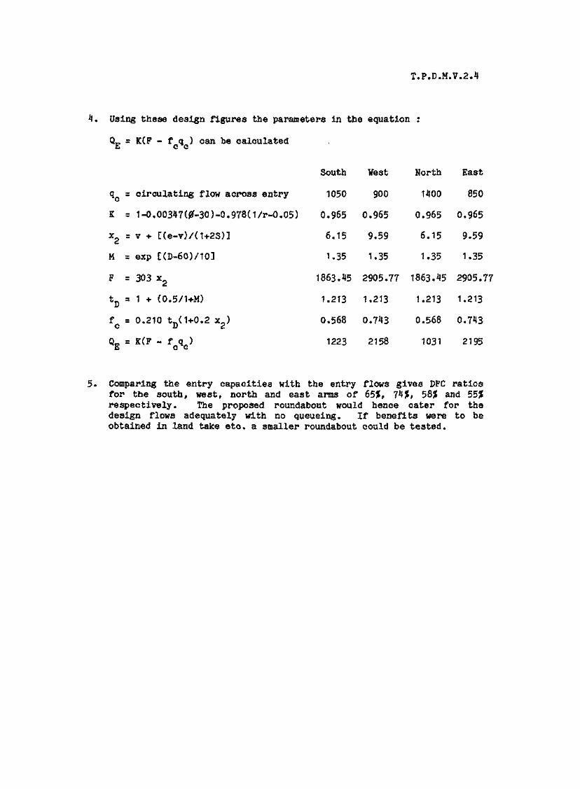
T.P.D.M.V.2.4
4. Using these design figures the parameters in the equation :
CL, a K{F - f q ) can be calculatedE C O
South Vest North East
qc as circulating flow across entry 1050 900 1400 850
K a 1^.00347(#-30)-0.978(1/r-0.05) 0.965 0.965 0.965 0.965
x^ = v + [(e-v)/(1+2S)] 6.15 9.59 6.15 9.59
M s exp t(D-6G)/103 1.35 U35 1.35 1.35
F = 303 x2 1863.45 2905.77 1863.45 2905.77
tD - 1 + (0.5/1+M) 1.213 1.213 1.213 1.213
f = 0.210 tn(1+0.2 x0) 0.568 0.743 0.568 0.743C D 2
Q- = K(F - f q > 1223 2158 1031 2195E C C
5. Comparing the entry capacities with the entry flows gives DFC ratiosfor the south, west, north and east anus of 65%, 74jt, 58$ and 55?frespectively. The proposed roundabout would hence cater for thedesign flows adequately with no queueing. If benefits were to beobtained in land take etc. a smaller roundabout could be tested.

T.P.D.MV, 24 .
VEHICLE ENTRYPATH CURVATURE
50m I FROM GIVE WAY LINE)-
THE RADIUS SHOULD K MHSURCDOVEROF 2C TO 25« H 1S Trtt M)N.
WHICH OCCURS ALONG THE APPROACHENTRY PATH IH THE VICtNITY OF THE'GIVEWT LWI BUT NOT MORE THANSO RI IN ADVANCE OF IT
DETERMINATION OF ENTW WTH CULTURE
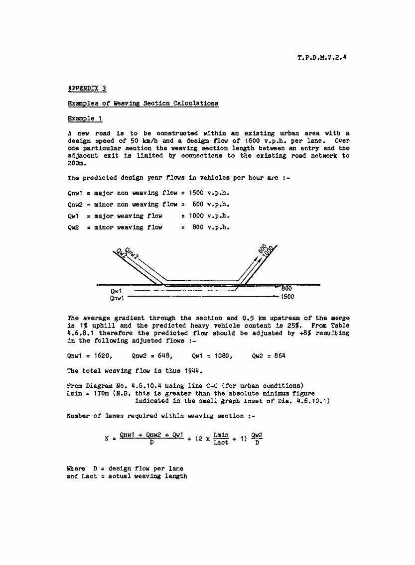
T.P.D.M.V.2.4
APPENDIX 3
Examples of Weaving Section Calculations
Example 1
A new road is to be constructed within an existing urban area with adesign speed of 50 km/h and a design flow of 1600 v.p.h. per lane* Overone particular section the weaving section length between an entry and theadjacent exit is limited by connections to the existing road network to200m.
The predicted design year flows in vehicles per hour are :-
Qnw1 s major non weaving flow s 1500 v.p.h.
Qnw2 = minor non weaving flow = 600 v.p.h.
Qw1 = major weaving flow = 1000 v.p.h.
Qw2 s minor weaving flow s 800 v.p.h.
Qw1Qnw1
"8001500
The average gradient through the section and 0.5 km upstream of the mergeis 1J uphill and the predicted heavy vehicle content is 2555. From Table4.6.8.1 therefore the predicted flow should be adjusted by 4-855 resultingin the following adjusted flows :-
Qnw1 r 1620, Qnw2 = 648, Qw1 - 1080, Qw2 s 864
The total weaving flow is thus 1944,
From Diagram No. 4.6.10.4 using line C~C (for urban conditions)Lmin = 170m (H.B. this is greater than the absolute minimum figure
indicated in the small graph inset of Dia. 4.6.10.1}
Number of lanes required within weaving section :-
Qnw1 + Qnw2 + Qw1 LminX Lact * 1)
Qw2
Where D = design flow per laneand Lact s actual weaving length
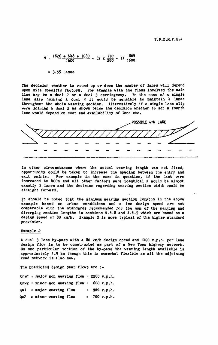
T.P.D.M.V.2.1!
J620 + 6*8 * 1080 , J70 , J5641600 4 {Z X 200 * U 1600
s 3-55 Lanes
The decision whether to round up or down the number of lanes will dependupon site specific ftctors. For example with the flows involved the mainline »ay be a dual 2 or a dual 3 carriageway. In the case of a singlelane slip Joining a dual 3 it would be sensible to maintain 4 lanesthroughout the whole weaving section. Alternatively if a single lane slipwere joining a dual 2 as shown below the decision whether to add a fourthlane would depend on cost and availability of land etc*
POSSIBLE 4th LANE
In other circumstances where the actual weaving length was not fixed,opportunity could be taken to increase the spacing between the entry andexit points* For example in the case in question, if the Lact wereincreased to iJOOm and all other factors were identical N would be almostexactly 3 lanes and the decision regarding weaving section width would bestraight forward.
It should be noted that the »inimu» weaving section lengths in the aboveexample based on urban conditions and a low design speed are notcomparable with the standards recommended for the sum of the merging anddiverging section lengths in sections 4.6.8 and Jf.6.9 which are based on adesign speed of 80 kro/h. Example 2 is more typical of the higher standardprovision.
Example 2
A dual 3 lane by-pass with a 80 k»/h design speed and 1*100 v.p.h. per lanedesign flow is to be constructed as part of a New Town highway network.On one particular section of the by-pass the weaving lengtti available isapproximately 1.5 km though this is somewhat flexible as all the adjoiningroad network is also new.
The predicted design year flows are :-
Qnw1 = major non weaving flow = 2200 v.p.h.
Qnw2 s minor non weaving flow a 600 v.p.h.
Qwt a major weaving flow s 900 v.p.h.
Qw2 s minor weaving flow * 700 v.p.h.

T*P*D*M.V.2.4
The average gradient through the section and 0.5 km upstream of the mergeis 2% downhill and the predicted heavy vehicle content is 15*. From Table4*6.8*1 therefore no adjustment is required to the predicted flows.
The total weaving flow is thus 1600 v.p.h.
From Diagram 4,6.10.1 using line B-B (for 80 km design speed and 1400v.p.h. per lane design flow) the minimum weaving section length Lmin s240m (N.B. this is taken from the small graph inset which produces alarger figure than the main graph).
Number of lanes required within weaving section ;«
M - Qnw1 + Qnw2 + Qw1 r. Lmin . Qw2N . g + C2 x — + 1> —
2200 + 600 + 900 ,*> 240 » 700* (2 -
H s 3.3 lanes
As the fractional part is small and the weaving flows are not relativelyhigh it would be advisable in this situation to maintain the dual threecharacter of the road and provide a three lanes wide weaving section. Thefull merging and diverging lane requirements as stated in sections 4.6*8and 4.6.9 would in any case be provided.
Consider also the situation which is the same in all respect except thatthe actual weaving section length is only 600m.
In these circumstances the number of lanes required in the weaving sectionwould be 3.54. When one considers the lengths of merging and diverging•lanes required there would be less than 200m between the end of one andthe beginning of the other* In this situation it would generally be moresensible to run the additional fourth lane throughout the whole section.

T.P.D.M.V.2.4
The average gradient through the section and 0*5 km upstream of the mergeis 2% downhill and the predicted heavy vehicle content is 15$. From Table4.6.8.1 therefore no adjustment is required to the predicted flows.
The total weaving flow is thus 1600 v«p.h.
From Diagram 4.6.10.1 using line B-B (for 80 km design speed and 1400v«p.h. per lane design flow) the minimum weaving section length Lmin s240m (N.B. this is taken from the small graph inset which produces alarger figure than the main graph)*
Number of lanes required within weaving section :-
u Qnw1 > Qnw2
w 2200 + 600 + 900 ^ „ 240 . 700N s + (2 x _ + 1} _
= 3-3 lanes
As the fractional part is small and the weaving flows are not relativelyhigh it would be advisable in this situation to maintain the dual threecharacter of the road and provide a three lanes wide weaving section. Thefull merging and diverging lane requirements as stated in sections 4.6.8and 4.6.9 would in any case be provided.
Consider also the situation which is the same in all respect except thatthe actual weaving section length is only 600m.
In these circumstances the number of lanes required in the weaving sectionwould be 3.54, Waen one considers the lengths of merging and diverginglanes required there would be less than 200m between the end of one andthe beginning of the other. In this situation it would generally be moresensible to run the additional fourth lane throughout the whole section.

Revised in March 2002
TRANSPORT PLANNING & DESIGN MANUAL
Volume 2
Chapter 5 - Other Facilities
Prepared by:Road Safety and Standards Division Transport Department
T.P.D.M. V.2.5(Al/2002)
ContentsSections
5.1 References
5.2 Introduction5.2.1 General
5.3 Petrol Pilling Stations in relation to Highway Design5.3.1 Location of Petrol Pilling Stations5.3.2 Layout of Petrol Pilling Stations
5.4 Additional Speed Control Facilities5.4.1 Definition5.4.2 Use5.4.3 Road Humps5.4.4 Transverse Yellow Bar Markings5.4.5 Rumble Areas5.4.6 Rumble Strips
5.5 Public Transport Oe-street Stopping Places5.5.1 Detailed Design Requirements5.5.2 General Considerations
5.6 Landscaping5.6.1 General5.6.2 Aspects Affecting Highway Design and Operations5.6.3 Guidelines for Considering Tree Planting Proposal
5.7 Lighting and Drainage5.7.1 Lighting5.7.2 Drainage
Tables
5.4.4.1 Patch Lengths and Spacing
Diagrams
5.4.3.1 Cross Section and Hump Dimensions5.4.3.2 Road Markings for Road Hump Installations5.4.3.3 Road Hump Installation

T.P.D.M. V.2.5
5.1 References
1. Chapter 8, Hong Kong Planning Standards and Guidelines
2. U.K. Department of Transport, Departmental Advice Note TA/36/83, Signing and Siting ofRoad Humps: Two-way, 2-lane roads
3. U.K. Highways (Road Humps) Regulations 1983
4. U.K. Department of Transport, Circular Roads 5/83, Road Humps
5. U.K. Department of Transport, Circular Roads 17/78, Transverse Yellow Bar Markings atRoundabouts
6. U.K. Department of Transport, Departmental Standard TD 6/79, Transverse Yellow ParMarkings at Roundabouts
1. T.R.R.L. Laboratory Report 800, TJie use of rumble areas to alert drivers
8. Code of Practice for the Lighting, Signing and Guarding of Road Works
9. Volume 3, Transport Planning and Design Manual - Traffic Signs and Road Markings
10. Civil Engineering Services Department, Civil Engineering Manual, Volume II, ProjectAdministration

T.P.D.M. V.2.5
5.2 Introduction
5.2.1 General
5.2.1.1 This Chapter is intended to provide information on facilities which may influence the design ofany road, or may be used to effect how any road is used.
5.2.1.2 It is important that consideration of the facilities mentioned in this Chapter is given at an earlystage in the design procedure. This is to ensure that the provision of the facility will notdetrimentally affect the design, e.g. that the location of a bus stop or filling station are consideredduring the design stage so that if they are required they can be sited at their optimum locationswhere visibility is maximised and interference with other road users is minimised rather thanhaving to fit them in when the design has been completed. Additionally, it should be ensuredthat the facility will not be required, at a later date e.g. curve radii and visibility at hazards aresufficient that rumble strips or similar will not need to be provided at some future time.

T.P.D.M. V.2.5(Al/2002)
5.3 Petrol Filling Stations in relation to Highway Design
5.3.1 Location of Petrol Filling Stations
5.3.1.1 Consideration must be given to what existing facilities are already available in the area whenapplications for new petrol filling stations or service areas, consisting of more than one petrolfilling station and other auxiliary services, are made. Except as otherwise specified, petrol fillingstation in this chapter refers to conventional petrol filling station, petrol cum liquefied petroleumgas filling station and liquefied petroleum gas filling station.
53.1.2 Petrol filling stations must be located such that interference with traffic flow on the frontage roadand any adjoining roads is minimised, and no additional traffic hazards are created.
5.3.1.3 Petrol filling stations should be located such that the journey distance for vehicles seeking petrolis minimised, but at the same time avoiding any undesirable increase in traffic flow in adjacent orsurrounding roads.
5.3.1.4 Turning movements into or out of the petrol filling station from/to the opposite traffic directionto the traffic immediately adjacent to it should be prevented. On Local Distributor Roads orbelow for example such movements can generally be tolerated.
5.3.1.5 Generally petrol filling stations should not be located adjacent to Trunk Roads and PrimaryDistributor Roads. However on Expressway, petrol filling stations should preferably form part ofservice areas.
5.3.1.6 It is desirable where two or more petrol filling stations are adjacent to each other that access toand from the main road is obtained via a common service road.
5.3.1.7 Sight distances in accordance with the minimum desirable standards on section 3.3.5 of Chapter3 should be provided on the approach to the service area or petrol fitting station, and for vehiclesleaving the service area or petrol filling station in accordance with section 4.3.8 of Chapter 4.
5.3.1.8 Service areas or petrol filling stations should preferably be sited opposite each other on dualcarriageway roads. If they are single carriageway roads then they should be staggered withinvisible distance of each other, but not less than 100m apart, with the nearside filling station beingthe nearest to the approaching traffic on that side.
5.3.1.9 Where it is agreed that a filling station should be provided on a Trunk Road, includingExpressways, or a Primary Distributor Road, or a Rural Road, the following must be takenaccount of:
(i) Filling stations should not be located on any slip road of a grade separated junction.
(ii) On Expressways the petrol filling station, or service area, should be at least 2km from anyintersection.
(iii) Merging and diverging lanes commensurate to the design standard of that road must beprovided at access and egress points to and from the service area or petrol filling station.
(iv) The spacing between petrol filling stations or service areas should be at least:
(a) 10 km on Expressways, and
(b) 5 km on Trunk Roads and Primary Distributor Roads.

T.P.D.M. V.2.5(Al/2002)
v) The service area or petrol filling station must not be located within 100m of a bend,vertical curve or road junction.
5.3.1.10 On roads other than Trunk Roads, Expressways, Primary Distributor Roads or Rural Roads, thelocation of petrol filling stations or service areas should be in accordance with the following:
(i) Where petrol filling stations on the same side of the road cannot be provided with acommon service road they should preferably be situated at least 300m apart
(ii) Petrol filling stations should not be located within 50m of a bend, vertical curve orjunction.
(iii) The carriageway width of the road on which the filling station fronts should not be lessthan 7.3m.

T.P.D.M. V.2.5(Al/2002)
53.2 Layout of Petrol Filling Stations
5.3.2.1 For petrol filling stations or service areas located adjacent to Trunk Roads, particularlyExpressways, Primary Distributor Roads and Rural Roads, as mentioned in section 5.3.1, thepetrol filling station or the service areas will be served by a specially provided service road withappropriate merging and diverging lanes. Any access by pedestrians on to the main road must beprevented by suitable fences if necessary. Although the waiting spaces must be provided inaccordance with section 5.3.2.2so that queuing traffic must not be extended on to the major roadand preferably not even on to the service road. A pedestrian footbridge may need to be providedto link the service areas on either side of the main road if a particular facility can only beprovided on one side. Also on Expressways the service area may be sited in conjunction with avehicle recovery centre or other facility associated with these types of road.
5.3.2.2 For all petrol filling stations a minimum of four waiting spaces should be provided within the sitein addition to one space for and adjacent to each metered filling point. However for a combinedpetrol filling and service station an additional four spaces should be provided for each servicebay. A service station being where activities such as general lubrication or tyre changing or carwashing, can be carried out. An additional space should be provided between each air-pumpingpoint. Waiting spaces must be easily accessible and located between the entrance and the pumps.
5.3.2.3 Only one entry point and one exit point is to be provided under normal circumstances and petrolfilling station shall be designed for one way operation to avoid reversion of vehicles and toprevent vehicles from taking short-cuts by entering via the egress point and leaving via theingress point.
5.3.2.4 However where the petrol filling station is bordered by two or more roads additional entrances orexits may be provided if internal circulation would neither disrupt traffic circulation on the roadsbordering the site nor adversely affect vehicle evacuation in emergency.
5.3.2.5 Any servicing must be carried out entirely within the petrol filling station area.
5.3.2.6 Where an existing footway fronting the site is less than 2.75m in width the site should be setback such that a footway of 2.75m minimum width can be provided. The length of the footwaybetween an entry and exit located on the same road and measured at the back of the footway mustnot be less than 3m but should preferably be 10m. The site must comply with any building orwidening lines and levels in the normal way.
5.3.2.7 A physical barrier must be constructed along the back of the footway to prevent vehicles fromcrossing the footway other than at the points of entrance or exit.
5.3.2.8 The minimum width at the back of the footway for the run-in and run-out should be 6.75m and5m respectively. Widening of the run-in and run-out towards the kerbline of the adjacentcarriageway to facilitate entry and exit is permitted but the widths at the kerbline should notnormally exceed 10m and 8m respectively. Where wider entrances or exits are required thesafety of pedestrians should not be adversely affected. Details regarding the layout of run-ins forfilling stations are illustrated in Diagram 3.6.3.3 of Chapter 3.
5.3.2.9 Buildings or other structures associated with the petrol filling station should not be erected suchthat they interfere with any sight lines required.
5.3.2.10 Where road lighting does not exist adjacent to the petrol filling station lighting must be providedto adequately illuminate the entrance and exit, but should not be of such type which will dazzlemotorists on adjacent roads.

T.P.D.M. V.2.5(Al/2002)
5.3.2.11 Appropriate "IN", "OUT", "NO ENTRY" and "NO EXIT" signs must be erected to indicate thepoints of entry and exit to and from the petrol filling station. For details, refer to paragraph2.3.2.91 of Chapter 2, Volume 3.
5.3.2.12 For details of environmental, fire safety and visual consideration, refer to Chapter 11 Section 3 ofHong Kong Planning Standards and Guidelines.

T.P.D.M. V.2.5
5.4 Additional Speed Control Facilities
5.4.1 Definition
5.4.1.1 Additional speed control facilities may be regarded as devices used in addition to speed limit andwarning signs where it is regarded that approach speeds to a particular hazard are excessive,though not necessarily above the speed limit in force, and warning signs alone are not consideredsufficient to bring to the attention of drivers the need to reduce their speed.
5.4.1.2 Additional speed control facilities may be in the form of a road marking or an actual physicalchange to the road surface, or both.

T.P.D.M. V.2.5(Al/2002)
5.4.2 Use
5.4.2.1 Additional speed control facilities will not generally be appropriate on Trunk Roads, includingExpressways, or Primary Distributor Roads, as normally the geometric design of the road shouldbe of a standard that the vehicle speeds do not need to be controlled by physical or other meansover and above the general traffic aids and design features normally provided. However inexceptional circumstances their use may be justified but each case will need to be considered onits own merit and care will be needed as to the type of facility installed.
5 A.2,2 On other roads the use of additional speed control facilities over and above the use of speedlimits maybe appropriate if it is considered that approach speeds to a particular hazard areexcessive, and as such a potential accident risk exists and warning signs or similar are notsufficient on their own to reduce the speed of approaching vehicles, or provide adequate warning,
5.4.2.3 Additional speed control facilities should only be used in unusual situations where conventionalwarning devices would not achieve the desired results.
5.4.2.4 It is very important that any additional speed control device proposed to be used is appropriatefor the type of road under consideration.
5.4.2.5 Certain additional speed control facilities mentioned will generate additional noise or causevibrations in vehicles, and it will be necessary to ensure that these will not cause annoyance orany danger to arise.
T.P.D.M. V.2.5(Al/2002)
5.43 Road Humps
5.4.3.1 A road hump is a raised device having a part circular shape of height not more than 75mm,installed across the full width of the carriageway at right angles to the direction of flow and whendriven across at speeds generally in excess of 15-20 km/h causes discomfort to occupants of thevehicle. The objective being to limit speeds to less than 20 km/h.
5.4.3.2 If road humps are installed on public roads careful attention must be given to their location, andthat they are properly signed in order to ensure that Government cannot be held responsibleshould an accident or damage to a vehicle occur.
5.4.3.3 In respect of any private roads, if road humps are required their design should follow the advicein this section. However, this advice should not in any way be taken as approval by theTransport Department for the provision of road humps on roads, and any road humps so installedremain in all aspects the responsibility of the Department or organisation installing them.
5.4.3.4 The cross section and dimensions of a road hump should conform to the dimensions given inDiagram 5.4.3.1. The hump should be installed across the full width of the road with 450 mmwide flat channel allowed on each kerbside for drainage.
5.4.3.5 Road humps maybe appropriate for two way 2-lane roads of width not greater than 10m andsubject to a speed limit of 50 km/h. However on two way 3 or 4 lane roads and one way streetsthe use of road humps is not advisable because of the possible dangers of vehicles overtaking oneanother on or near the humps. On any road subject to a speed limit greater than 50 km/h roadhumps should never be used.
5.4.3.6 A road hump installation may comprise either a single hump or a series of humps up to 20 innumber. For locations where a series of road humps are used the following is applicable
(i) Spacing between consecutive humps should be not less than 50m nor more than 150m.
(ii) On roads which have gradients of more than 10% the maximum spacing should be reducedto 70m.
(iii) A series of road humps should not extend for more than 1 km.
5.4.3.7 With regard to the siting of road hump installations, they should generally not be located, otherthan in special circumstances:
(i) Within 8m of a road junction.
(ii) Within 18m of the tangent point of a bend with an inner kerb radius of less than 50 metresand which requires a vehicle to change direction by more than 45 degrees.
(iii) On the crossing itself, or within 30m of the crossing or within the limits of the zebracontrolled area whichever is the greater.
(iv) Within 70m either side of a signal controlled crossing,
(v) Within 50m of a cautionary crossing place.
(vi) On or within 20m of a light rail road crossing or similar, the 20m being measured from therunning rail of the track nearest the hump.
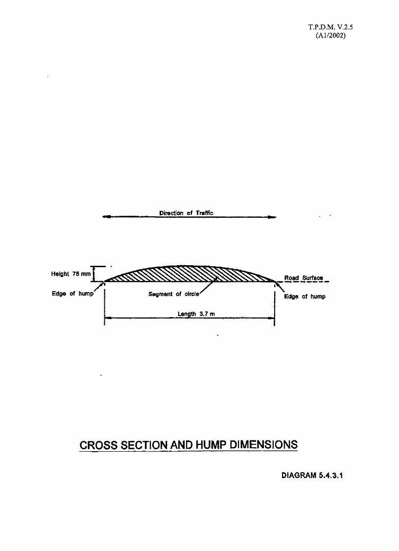
T.P.D.M. V.2.5(Al/2002)
Direction of Traffic
Height 75 snm
Edge of hump' Segment of circle
Length 3.7m
Road Surface
Edge of hump
CROSS SECTION AND HUMP DIMENSIONS
DIAGRAM 5.4,3.1
T.P.D.M. V.2.5(Al/2002)
(vii) Within 25m of the nearest part of a structure over a road of which any part is 6.5m or lessabove the surface of the carriageway.
(viii) Within 20m of any fire hydrant positioned along the footway of the road.
(ix) Where street lighting which operates throughout the hours of darkness is not available, andpreferably a lighting column should be within 5m of any hump.
(x) Opposite any run-in, or any position where they might interfere with access to the run-in.
(xi) Over any manhole cover, or where they might interfere with access to public utilityapparatus.
(xii) On or within 25m of any road carrying structure, such as a bridge, subway or culvert, inorder to avoid the risk of structural damage occurring because of the increase in impactloading and vibration.
(xiii) In or within 25m of any tunnel,
(xiv) Within 20m of any parking place.
(xv) Within 20m of a bus stop sign or within 10m of the bus stop road markings 1047 and1048, or the public light bus or taxi stand marking 1049.
(xvi) Within 20m of the summit of a gradient of more than 10%.
5.4.3.8 Road humps should not normally be installed on roads forming part of a public transport route,because of the possible delay and discomfort caused to passengers. However if it is agreed afterconsultation with the appropriate public transport company or companies to install road humps,the height of any road hump should not be greater than 75mm.
5.4.3.9 It is generally advisable, in order to ensure vehicle speeds are not excessive when approaching aroad hump, that the road where humps are installed incorporate wherever possible one or more ofthe following features:
(i) Vehicles enter the road through a junction where they have to change direction by not lessthan 70 degrees with an inner turning radius of not more than 25m.
(ii) There is a bend along the road which changes the direction of vehicles by not less than 70degrees with an inner kerb radius of not more than 25m.
(iii) The road is a cul-de-sac.
(iv) Access is restricted to certain types of vehicles only.
(v) The road does not provide a through route between major roads.
(vi) Side road junctions along the humped road are generally at right angles to the humpedroad.

T.P.D.M. V.2.5(Al/2002)
5.4.3.10 If the road under consideration does incorporate one or more of the features referred to inparagraph 5.4.3.9 then to further ensure that approach speeds are not excessive it is suggestedthat road humps should be located at a distance from the feature in accordance with thefollowing:
(i) At or about 30m of the entry junction.
(ii) Approximately 30m beyond a horizontal bend, though this may need to be increaseddepending on whether the road hump warning traffic sign 539 can be located satisfactorilywith sufficient visibility distance.
(iii) Approximately 30m from the closed end or turning area of a cul-de-sac, so that vehiclescoming from that direction are not encouraged to increase their speed substantially.
(iv) Approximately 30m from the point where the restriction on vehicle access applies.
5.4.3.11 The use of road humps on roads with steep gradients is not recommended as in the uphilldirection slower vehicles can find them difficult to negotiate and under adverse weatherconditions in both directions of travel they are potentially dangerous.
5.4.3.12 It is relevant that noise will be generated when vehicles pass over the humps and vehicles such asempty or lightly laden goods vehicles can be a considerable nuisance in this respect, and thisshould be taken into account before road humps are installed.
5.4.3.13 Road markings in accordance with Diagram 5.4.3.2 must be laid at the approaches to a roadhump, using suitable reflective material.
5.4.3.14 The warning line pattern is that generally associated with higher speed roads but is used toensure that warning line mark can be laid across the road hump.
5.4.3.15 The warning lines should commence from at least the point where the warning sign, traffic sign539 "Road Hump or Series of Road Humps Ahead", is erected, and in the case where a roadhump is situated within 30m of a road junction, the warning line pattern should commence fromthe junction.
5.4.3.16 If there are stopping restrictions where humps are installed the edge line markings can beomitted, as the appropriate yellow line markings can substitute for these.
5.4.3.17 Traffic sign 539 "Road Hump or Series of Road Humps Ahead" should, subject to paragraph5.3.3.18 be generally placed approximately 45m in advance of a road hump, or where a series ofroad humps are used in advance of the first or leading road hump, and the sign should have aminimum clear visibility distance of approximately 60m.
5.4.3.18 Where a road hump or series of humps commences at or within 50m of a junction, the traffic signShould be erected not closer than 5m and not greater than 15m from that junction.
5.4.3.19 Where a series of road humps are used, the supplementary plate 784, "For 1 km", or a suitableequivalent, should be used in conjunction with the traffic sign, to indicate the extent of the seriesof humps.
5.4.3.20 It is not necessary to use intermediary warning signs with a series of humps, other than when aside road junction occurs within the series. In these locations the traffic sign should be erectedwithout supplementary plate, traffic sign 784, at the normal siting distance in accordance withparagraph 5.4.3.17, if this is possible, or if not in accordance with paragraph 5.4.3.18.
5.4.3.21 Diagram 5.4.3.3 shows an example of a road hump installation.
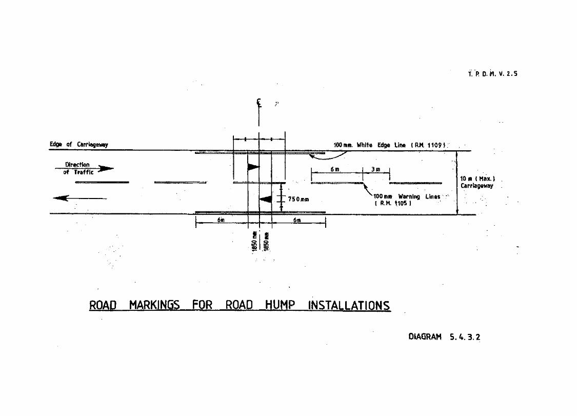
1 R D. M, V. 2.5
Edge of Carriageway
Direction «^_of Traffic - ppw
1 , 6in
M».
«flC^; -i
^
6m
100mm. White
£. ffi a— oni. 3
v,_J
Edge Line C FIM. 11091
' ;••
00 mm Warning Linus( R.M, 1105 J
10 m ( Max. )Carriageway
i
ROAD MARKINGS FOR ROAD HUMP INSTALLATIONS
DIAORAM S.4.3.2
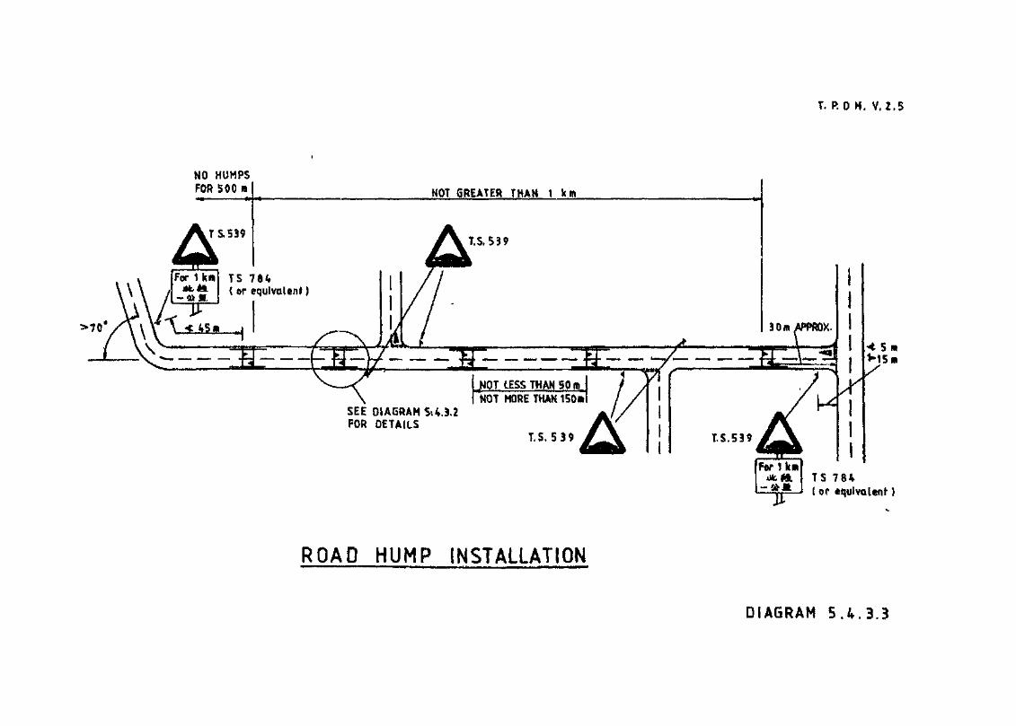
T. R 0 M. V. 2.5
HO HUHPSFOR 500 ra NOT GREATER THAN 1 km
SEE DIAGRAMFOR DETAILS
ROAD HUMP INSTALLATION
DIAGRAM 5 . 4 . 3 . 3
T.P.D.M. V.2.5(Al/2002)
5.4.4 Transverse Yellow Bar Markings
5.4.4.1 This type of "additional speed control device", consist of 90 No. markings, 600mm in width laidat right angles to the carriageway over a 400m length, with the spacing between successivemarkings becoming progressively smaller as the hazard is approached.
5.4.4.2 The effect of the markings is to distort the driver's perception as to the actual speed beingtravelled thus creating the impression that the vehicle is actually "speeding up" and soencouraging the driver to slow down.
5.4.4.3 This type of "additional speed control device" can be used on high speed approaches toroundabouts, toll booth, slip roads etc.
5.4.4.4 for any location its use should generally not be considered other than when the followingconditions occur:
(i) the road should be a dual carriageway road, or a direct extension of a dual carriagewayroad, as in the case of a slip road leading to a roundabout.
(ii) the road should be subject to a speed limit of not less than 70 km/h.
(iii) there should be at least 1 km of dual carriageway with no major intersections or severebends before the location.
(iv) for existing roads accident statistics should indicate that at the location speed or speedmisjudgment was a predominant factor.
5.4.4.5 Details of the actual marking and the setting out procedures are given in Volume 3, Chapter 5and should be followed. Modifications to the arrangement to obtain a shorter length of markingswill not achieve the desired effect and therefore is generally not recommended. However wherethere is insufficient length for the full set of markings to be laid on a slip road, some reduction isacceptable, but there should be at least 50 No. of the transverse marks, i.e. Dl to D50, inaccordance with Table 5.6.5.1 of Volume 3, Chapter 5.
5.4.4.6 The markings must be laid in a suitable durable reflective material, and it is relevant to note thatassuming a two lane approach some 360 square metres to 400 square metres of material will berequired. Because of the large amount of material used the initial cost of providing the markingwill be relatively high. To remain effective replacement will be required every two to threeyears, and on some roads even more frequently. Therefore because of the relatively high cost ofproviding and maintaining these makings it is essential in order to justify this expense that theusefulness of the marking at any particular location can be properly demonstrated.

T.P.D.M. V.2.5(Al/2002)
5.4.5 Rumble Areas
5.4.5.1 Rumble areas are patches of rough coarse road surface which produce aural and tactile stimuliinside a vehicle with the intention of alerting drivers to a particular hazard ahead.
5.4.5.2 Research in the UK TRRL Report 800 has however indicated that although these devices mayreduce the number of accidents occurring at a particular hazard they do not necessarily reducethe approach speed of vehicles, and therefore if the latter is required these type of devices maynot be appropriate.
5.4.5.3 Appropriate material for the patches has found to be 13-19mm roadstone set onto the roadsurface using epoxy resin, and further details of this can be found in TRRL Report 800.
5.4.5.4 Six patches should normally be used to form the complete rumble area, which should normallyend at least 100m before the hazard.
5.4.5.5 Rumble areas are generally only appropriate for two way 2-lane carriageways because of possibledangers that might occur with vehicles overtaking and simultaneously passing over the patches,however they have been used in other countries on a dual carriageway approach to a round about.
5.4.5.6 It is only necessary to lay patches on the approach lane to the hazard and not the full width of thecarriageway or carriageways as vehicles in the opposite direction are proceeding away from thehazard. However this can in the case of single carriageway roads sometimes lead to vehiclescrossing over onto the adjacent lane for opposing traffic in order to avoid the rumble areas, andtherefore care has to be taken as to the siting of rumble areas that there is adequate visibility.Alternatively it maybe appropriate to consider the use of double white lines to confine vehicles totheir lanes.
5.4.5.7 The precise method of determining the length of the patches and the spaces between can befound in TRRL Report 800, which assumes a linear decelaration between points 250m and 100mbefore the hazard and calculating the positions and lengths of the patches accordingly. Howeverconditions in the Territory are such that uniform speeds can generally be assumed. Based on thisassumption Table 5.4.4.1 gives the length of the patches and spaces between them for various 85percentile approach speeds.
Table 5.4.4.1Patch Lengths and Spacing
85 percentile speedkm/h
60
70
80
90
Patch Lengthm
5.69
7.08
8.47
9.9
Space between patchedffi
10.96
12.36
13.75
15.1
iRumble strip Length
IB
100
116.64
133.3
150

T.P.D.M. V.2.5(Al/2002)
5.4.5.8 Using Table 5.4.4.1 appropriate patch lengths can be obtained by rounding the actual 85percentile speed to the nearest 85 percentile speed given in the Table. The first patch ispositioned at 100m from the hazard with the five other patches spaced in accordance with thedistances given in Table 5.4.4.1. Some adjustment of the first patch can be made where it isconsidered appropriate, i.e. because of the presence of a bend or similar but this adjustmentshould not generally result in the patch nearest to the hazard being located closer than 80m orfarther away than 150m. Further patches can also be added if considered appropriate but thisshould not generally result in more than eight patches being used.
5.4.5.9 On the approach to the rumble area, traffic sign 434, "Uneven road" should be erected inaccordance with Table 2.2.2.1, of Chapter 2, Volume 3. It may also be appropriate to use thesupplementary plate, traffic sign, 784, or equivalent, indicating the distance over which the areaextends.
5.4.5.10 Noise can be generated by the rumble areas and the possible effect of this will need to beevaluated if there are any residential developments, Hospitals or Schools, adjacent to the road.
5.4.5.11 It should also be noted that the cost of installation and subsequent maintenance of rumble areascan be relatively high, and therefore it is necessary to ensure that this expense is justified beforeany rumble areas are agreed to.

T.P.D.M. V.2.5
5.4.6 Rumble Strips
5.4.6.1 Rumble strips are a further aural and tactile warning device very similar to rumble areas, butrather than broad patches consist of narrow strips placed at regular intervals, normally used onsingle carriageway roads, but may in certain circumstances be appropriate on dual carriagewayroads.
5.4.6.2 Various types of material have been used including raised concrete strips, but these are notrecommended. However, strips formed from 13mm-19mm road stone chippings set onto the roadsurface by using epoxy resin have had some degree of success and are generally recommendedwhere it is considered that rumble strips should be provided.
j.4.6.3 The rumble strips formed from roadstone chippings should be 1m wide spaced at intervals of 7mapart, with at least 20 No. being used, and laid only on the approach to the hazard.
5.4.6.4 The location of the rumble strips should be in advance of any warning sign warning of the hazardand generally not closer than 30m to such a sign.
L4.6.5 Rumble strips like rumble areas do not necessarily reduce the approach speed of vehicles, and infact evidence is that only slight reductions in speed are obtained. However they do act a "wakeup" device, which does alert drivers to the hazard ahead and in this respect have been found toreduce accidents.
i.4.6.6 Rumble strips can cause problems in respect of the noise generated and the vibration effectcaused. In the case of the former careful consideration must be given regarding the use of rumblestrips if there are residential developments or hospitals or schools nearby, particularly if unladengoods vehicles are likely to use the route as these can be the worst offenders. In respect of thevibration effect these can cause goods to be dislodged, and given that many goods vehicleoperators do not pay proper attention to the loading of their vehicles it may not be advisable touse rumble strips on route heavily used by these vehicles.
.4.6.7 Rumble strips of whatever type should not be used in marginal strips or hard shoulders to warn ofadjacent barrier fences. Apart from the fact they interfere with the drainage and collect rubbish, itis far safer to leave the marginal strip vacant of any kind of obstruction. Additionally in the eventof a vehicle breaking down there is less liklihood'of the vehicle being moved onto the marginalstrip because of the obstruction caused by the rumble strips. Also it is likely to cause occupantsof the vehicle to walk along the cariageway rather than the marginal strip to avoid the rumblestrips.
.4.6.8 The provision of narrow transverse rumble strips to separate a carriageway from an adjacent tramlane or similar, or to separate merging/diverging carriageways is not recommended, as these areof doubtful value and may in fact increase the potential for an accident to occur rather thandecrease it. It is also relevant that they do not actually prevent a vehicle straying onto thesupposedly "protected" area and depending on the type of rumble strip and the type of vehiclethey could cause the vehicle to be trapped in that area even if only momentarily. These types ofrumble strips can also be potentially dangerous to cyclists and motor cyclists.
.4.6.9 At the start of the rumble strips, described in paragraphs 5.4.6.2 and 5.4.6.3 traffic sign 454"Uneven road" should be erected in accordance with Table 2.2.2.1 of Chapter 5, Volume 5,together with the supplementary plate, traffic sign 784, indicating the distance over which therumble strips extend.
.4.6.10 As with rumble areas, drivers on the approaches to rumble strips may in order to avoid them,travel on the offside of the road where strips have not been laid. If this is likely to cause aproblem the use of double white lines to prevent this may need to be considered.

T.P.D.M. V.2.5
5.4.6.11 As with rumble areas, rumble strips can be relatively expensive to install and maintain andtherefore it is necessary to ensure that this expense is fully justified before agreeing to theinstallation of rumble strips.

T.P.D.M. V.2.5(Al/2002)
5.5 Public Transport Oil-street Stopping Places
5.5.1 Detailed Design Requirements
5.5.1.1 The detailed design requirements and dimensions for all types of public transport on-streetstopping places are given in the various chapters of Volume 9.
5.5.1.2 The purpose of this section is merely to bring to the attention of the designer the various facilitiesthat may need to be considered.

T.P.D.M. V.2.5(Al/2002)
5.5.2 General Considerations
5.5.2.1 The necessity to provide on-street public transport stopping places will depend very much on thetype of highway scheme that is being designed, but early consultation with the appropriateTransport Operations Divisions of the Transport Department should be made to ascertainwhether any or all of the following are required:
(i) Franchised Bus Stopping Places;
(ii) PLB Stands or Stopping Places;
(iii) Taxi Stands;
(iv) Non-franchised Bus Stopping Places.
5.5.2.2 On-street public transport stopping places should not normally be provided on Trunk Road,Primary Distributor Roads and Rural Roads having no frontage access. Consideration will needto be given as to where appropriate and convenient stopping places can be located adjacent tothese routes.
5.5.2.3 Bus stopping places should normally not be provided on slip roads as this can interfere with themovement of other traffic, and the presence of pedestrians along these roads where traffic speedsare still relatively high may be detrimental to road safety. However, in certain situation theremay be no alternative other than to locate the bus stop along a slip road. In these cases althougheach situation will need to be considered separately it will be important to ensure that thefollowing points are taken into account:
(i) That buses do not stop on the running carriageway;
(ii) That buses emerging from the bus stop can do so safely, and in this respect that the driverof the bus can adequately see through his rear mirror vehicles approaching in the streamthe bus is to be driven into;
(iii) That pedestrians can safely reach and leave the bus stop area, preferably without crossingthe slip road at grade:
(iv) That pedestrians can safely wait at the bus stop and are discouraged from wandering ontothe slip road.
5.5.2.4 In terms of providing convenient stopping places for franchised buses adjacent to high speedroads, consideration should be given early in the design stage as to whether bus only slip roads,perhaps as a link between the main slip roads can be provided. However such facilities shouldnot be provided for red minibuses and any stopping places for these should be situated away fromany slip roads or major junctions.
5.5.2.5 Taxi and Public Light Bus stands will normally only be appropriate for categories of road oflocal distributor road status or less.

T.P.D.M. V.2.5(Al/2002)
5.6 Landscaping
5.6.1 General
5.6.1.1 Considerable benefit can be obtained in terms of the general appearance, and lessening theimpact of a highway project scheme on the surrounding environment by the use oflandscaping techniques. Planting, if properly designed, can reduce visual impacts such asvisual intrusion, monotony and glare. It can also help to break down noxious gas emittedfrom vehicles. In addition, landscape earth bunds can serve as noise mitigation measure.Furthermore, landscape planting can be used to create a green environment for pedestriansby creating visual interest, reducing temperature of roads by providing shade and absorbingradiation from the sun, enhancing humidity of the air etc. The planning and design ofpedestrianisation scheme are covered in TPDM Volume 6 Chapter 10.
5.6.1.2 Early inclusion of landscaping requirement both in the feasibility study of a road project andat the planning/design stage is necessary if the full benefits of suitable landscaping are to beobtained. Landscape works which may include tree planting should be designed as anintegral part of the transport corridor. Any additional land provision for landscaping may beidentified and allowed for. The planting area shall be free of disturbance from undergroundutilities. Furthermore, tree preservation should be thoroughly considered at theplanning/design stage of the works.
5.6.1.3 Consultation with the relevant body should also be carried out in respect of any landscapingadjacent to overhead cables of tram, or vehicles of the Mass Transit Railway CorporationLimited or Kowloon Canton Railway Corporation.

T.P.D.M. V.2.5(Al/2002)
5.6.2 Aspects Affecting Highway Design and Operations
5.6.2.1 It is beyond the scope of this manual to give landscaping design details. However,landscaping should be provided with full consideration of highway design and just asimportantly road safety. Wherever possible, access to the landscaped areas from thecarriageway of the expressway should be avoided.
5.6.2.2 Planting should be provided in areas where they do not interfere with the sight line andvisibility requirements in respect of the following aspects:
(i) Volume 2, Chapter 3 Section 3.3.5 for sightlines along a road;
(ii) Volume 2, Chapter 4, Section 4.3.8 for visibility splays at junctions;
(iii) Volume 2, Chapter 4, Section 4.5.11 for visibility on and at the approaches toroundabouts;
(iv) Volume 2 Chapter 6, Section 6.4.2 for visibility envelope for road side signs; and
(v) Volume 3 Chapter 3 Section 3.2.3 for visibility of directional signs.
On the central reserve of a dual carriageway approach to a roundabout and the central islandof roundabout with diameter less than 10m where tree planting is restricted for preservationof visibility, groundcovers, turf or low shrubs can be planted. In some cases, it may beacceptable to plant a small upright tree/palm with narrow trunks. If future growth of anyplants will interfere with sight lines, the planting should be initially set far enough back toensure that they will not cause any interference problem.
5.6.2.3 It is important that any planting does not obscure traffic signs and light signals. Whilstobviously arrangements can be made for cutting back overhanging branches it is preferablethat account of this is taken in the design stage and planting should be provided sufficientlyaway from the traffic signs and light signals with the clear visibility distances given inChapters 2 and 3 of Volume 3.
5.6.2.4 For expressway and other high speed roads, only such low plant can be planted within thetriangular visibility envelope in front of all road side signs to ensure that the signs can beclearly read by approaching traffic. The visibility distances for directional signs and thevisibility envelope are given in Chapter 6 Section 6.4.2. It is also important that the plantingdoes not hinder the operation of speed enforcement cameras and traffic surveillanceequipment/facilities, such as CCTV cameras, automatic incident detectors, policeobservation spots etc.
5.6.2.5 The safe operation of the road as well as the method of maintaining any planting or otherelements associated with landscaping should be considered at the design stage. In thisrespect, the maintenance and/or tree felling authorities for landscape hardworks andsoftworks should be consulted on the proposals before they are implemented and preferablyduring the design process.
5.6.2.6 Lane closure for general road maintenance and cleansing is regularly carried out byHighways Department for primary distributors and high speed roads. The horticulturalmaintenance authority may also take this opportunity to carry out the planting maintenanceworks.

TJP.D.M. V.2.5(Al/2002)
5.6.2.7 In the planting design for central reserve, visibility shall not be interfered and the width ofcentral reserve shall be suitably widened if necessary to provide sufficient space for theplants to grow to their full size without encroaching on the carriageway. If future growth ofplants will interfere with sight lines, the planting should be initially set far enough back toensure that they will not cause any interference problem. Watering of plants from the fastlane will not be permitted as it will cause traffic disruption. Therefore, an automaticirrigation system for watering should be installed unless the type of planting does notrequire watering to avoid maintenance vehicles having to stop on the carriageway.Alternative access must be provided to the central reserve or arrangements made for theutilisation of cyclic lane closure. In this respect it may be possible to provide a pedestrianaccess for personnel from an elevated road or footbridge spanning over the carriageway inquestion. Care must also be taken to ensure that on curved sections of road, any planting inthe central reserve does not obscure forward visibility for traffic in the fast lane, and if toachieve the required safe stopping distance it is necessary that only low shrubs or smallupright tree/palm with narrow trunks can be planted on the central reserve within the sightline envelope.
5.6.2.8 If tree planting is planned for verges, embankment, cuttings or similar, along Trunk Roads,expressways or Primary Distributor Roads or Rural Roads, it will be necessary to provide apiped water supply so that any watering required for the establishment of the trees can betaken from this supply rather than water tankers parked at the side of the road. However, thepiped water supply is considered not necessary for small isolated planting areas, such as toeplanters to slopes and remote rural areas, or hydroseeded areas or native woodland plantingfor which water supply from natural rainfall should be sufficient.
5.6.2.9 Where planting is agreed in respect of verges on expressways, Trunk Roads and PrimaryDistributor Roads, the 3m verge incorporating a marginal strip and provided in accordancewith Section 3.4.9 of Volume 2 Chapter 3, must be kept clear of all trees, shrubs, hedges orsimilar, as this area is required for vehicles to pull off in the event of a breakdown.
5.6.2.10 On slip roads or flyovers, because of the tight geometry usually employed, it is not desirablefrom a road safety point of view for vehicles to be parked or personnel to be working fromthe carriageway, and if planting adjacent to these is required consideration must be given asto how these actions can be avoided in respect of any future maintenance operations beforesuch planting is agreed.
5.6.2.11 Landscaping designs should ensure, as far as possible, that any proposed planting or otherlandscape features and any subsequent growth of the plants would not induce severeinterference and disruption to existing road lighting, CCTVs and Red Light Cameras etc,and their subsequent operation and maintenance. If the existing road lighting is beingshaded by the subsequent growth of plants, the maintenance agents for trees or light polesshould carry out appropriate measure to rectify the situations. It can be in the form ofproper tree works to lift the tree canopy or to remove branches causing disruption, ormodification and relocation of the existing light pole.

T.P.D.M. V.2.5(Al/2002)
5.6.2.12 Where it is accepted that the maintenance of any planting or other landscape features, has tobe achieved from the carriageway, it is imperative that the advice on the signing and otherprocedures in the Code of Practice for the Lighting, Signing and Guarding of Road Works isfollowed, and account of this is taken in the planning of maintenance programmes. In thecase of expressways, this will entail the closure of a lane or lanes if vehicles are to bestopped on the carriageway. Failure to follow the procedures may prejudice the safety ofpersonnel engaged in maintenance work and may also make them liable to prosecution.Consultation with the Police and the Highways and Transport Departments is also requiredwhere works are to be carried out on or from the carriageway.
5.6.2.13 In landscaping design, the effects of planting and its subsequent growth on vehicular trafficshould be considered in conjunction with pedestrian traffic. Raised planters adjacent tofootway can provide a very attractive feature and improved pedestrian environment,however additional footway width should be provided to allow for any shrubs or bushes inthe planters over the footway as they will reduce the effective footway width. For moredetails, refer to Volume 6 Chapters 8 and 10. To ensure that the planters in the vicinity ofcrossings will not obscure pedestrians, in particular children, from the view of approachingvehicle drivers, nor interfere sight lines of pedestrians to such vehicles, the overall height ofthe planters including shrubs should not exceed 0,5 m within 30 m on the approach to acrossing.
5.6.2.14 Landscaping designs on highway structures should ensure that any planting or subsequentgrowth of plants would not affect the integrity of the structures nor affect their inspectionand maintenance. Except landscape plantings which have been properly considered in thedesign stage, only creepers grown on dedicated frames and small shrubs in portable plantersare allowed on highway structures. Direct placement of soil onto structural elements whichare not designed for this use must be avoided as they will obstruct the inspection andmaintenance of highway structures. Particular attention must be paid to root growth andirrigation seepage that are detrimental to the well-being of structural elements which are notinstalled with suitable protections.
5.6.2.15 For expressways, consideration must be given when landscape proposals include theplanting of trees, that future growth will not result in them becoming a substantialobstruction which would necessitate the provision of protective barrier fences. In thisrespect, groundcovers, turf, low shrubs or other suitable species may be considered to beplanted within 5m from the rear of the shoulder.
5.6.2.16 Landscape designs which require frequent and regular maintenance whether by persons onfoot or in slow moving vehicles, increases the risk to operatives and other road users,whatever warning signing procedures are adopted, and must therefore be avoided, ifpossible.
T.P.D.M. V.2.5(A 1/2002)
5.6.3 Guidelines for Considering Tree Planting Proposal
5.6.3.1 Tree planting proposals should be considered flexibly to promote greening opportunitywhilst ensuring road safety. The following serve as a checklist only and the trafficengineering requirements should be checked for each tree planting location:
(i) Trees should be planted clear of traffic light signals and/or traffic signs to ensure theirvisibility. Furthermore, they should not be planted in such locations as to hinder theoperation and maintenance of speed enforcement cameras and traffic surveillanceequipment/facilities, such as CCTV cameras, automatic incident detectors, policeobservation spots, etc.
(ii) Trees should be planted at least 5 m (measured along the carriageway) away from theapproach side of a pedestrian crossing, run-in or a bus stop.
(iii) Trees should be planted at least 10 m (measured along the carriageway) away from aroad junction.
(iv) A minimum lateral clearance of 500 mm should be maintained between the outsidepart of the tree trunk including tree guard and kerbside. This dimension should beincreased to 1.0m for high speed roads with a design speed or speed limit of 70 km/hor above.
(v) Adequate footpath width should be maintained to cater for pedestrian traffic. Pleaserefer to Volume 2 Chapter 3 Section 3.4.11 for the minimum width of clear footpathto be maintained.
(vi) For avenue/street tree planting the trees should normally be spaced at a minimumdistance of 5 m from centre to centre. However, such requirement is not applicable ifthe trees are planted at the back of footpath or in the central reservation.
(vii) Partial overhang of tree planting should have a minimum height clearance of 5.5 m.Overhang on footpath and cycle track should have a minimum height of 2.5 m.
(viii) Trees planted within visibility splays should be selected with a high canopy andslender trunk to ensure that only minimal obstruction of driver vision is effected bythe stem.
(ix) Trees should be planted at least 5 m from existing street lighting to avoid shadingeffect.
(x) Agreement should be obtained from the relevant maintenance authority for the futuremaintenance of tree, including trimming of branches, felling and transplanting ifnecessary due to traffic management schemes. In this respect, Works BranchTechnical Circular No. 18/94 and 24/94 (or updated versions) can be referred.
5.6.3.2 Tree planting, including small canopy trees, upright tree/palm with narrow trunks, turf,groundcovers or low shrubs, is allowed along kerbside as long as they will not causesightline and visibility problems. Alternatively, trees can be planted away from the kerb,such as at the back of footpath.

T.P.D.M. V.2.5(Al/2002)
5.6.3.3 Trees should not normally be planted in areas which will be affected by planned roadimprovements in the foreseeable future unless they are transplantable or in containers.However, temporary landscape that may consist of hydroseeding and/or tree/shrub plantingmay be required to mitigate the potential landscape and visual impacts. The scope oftemporary landscape works would be advised by the relevant authority on a case by casebasis. The authority responsible for the new works/development shall be responsible for theapplication for the removal of the trees when the need arises in future.

T.P.D.M. V.2.5(Al/2002)
5.7 Lighting and Drainage
5.7.1 LigfatiEg
5.7.1.1 Adequate lighting must be provided to all public roads. The advice of the Lighting Divisionof Highways Department on the design of lighting should be obtained.
5.7.1.2 Lighting columns are best located at the back of the footpath or verge to reduce obstructionand give maximum and give maximum clearance.
5.7.2 Drainage
5.7.2.1 Adequate drainage of pavement and storm water must be provided and the advice ofHighways Department (or the maintaining authority if not HyD) should be obtained onexclusive highway drainage, and that of Drainage Services Department for carrier drains ormain drainage.

Revised in March 2002
TRANSPORT PLANNING & DESIGN MANUAL
Volume 2
Chapter 6 - Expressways
Prepared by:Road Safety and Standards Division Transport Department
T.RD.M.V.2.6(Al/2002)
Contents
Sections
6.1 Reference
6.2 Introduction6.2.1 General
6.3 Expressway Design Standards6.3.1 Design Speed6.3.2 Horizontal and Vertical Alignment6.3.3 Cross Section6.3.4 Drainage Considerations6.3.5 Boundary Fences6.3.6 Junctions6.3.7 Access
6.4 Permanent Signs and Road Markings6.4.1 General6.4.2 Directional Signs6.4.3 Chainage Markers6.4.4 Road Markings and Road Studs
6.5 Lane and Carriageway Closures6.5.1 General Requirements
6.6 Maintenance Operations Centres (MOC)6.6.1 Location and Use
6.7 Service Areas6.7.1 Location6.7.2 Facilities
6.8 Operation and Management6.8.1 Utility Services6.8.2 Activities affecting operation6.8.3 Emergency Telephones6.8.4 Traffic Control and Surveillance Equipment6.8.5 Vehicle Recovery
Tables
6.3.1.1 Expressway Design Speeds
6.4.2.1 Sign Locations6.4.2.2 Visibility Distances for Directional Signs

T.P.DJVLV.2.6(Al/2002)
Diagrams
6.3.3.1 Rural Expressway - Typical Cross Section on Embankments6.3.3.2 Rural Expressway - Typical Cross Section in Cutting6.3.3.3 Rural Expressway - Cross Section Where Full Hard Shoulder Cannot be Provided6.3.3.4 Urban Expressway - Typical Cross Section on Embankments6.3.3.5 Urban Expressway - Typical Cross Section in Cutting6.3.3.6 Elevated Expressway - Typical Cross Section6.3.3.7 Expressways in Depressed Roadway6.3.3.8 Expressway Link Road, Depressed or Elevated, Typical Cross Sections6.3.3.9 Expressway Slip Roads - Typical Cross Section6.3.3.10 Expressway Slip Roads, Where Full Width Hard Shoulders Cannot Be Provided6.3.3.11 Marginal Strip to Hard Shoulder Tapers6.3.6.1 Expressway Merging Lanes (Design Speed 100 km/h or less)6.3.6.2 Expressway Merging Lanes (Design Speed 100 km/h or less)6.3.6.3 Expressway Merging Lanes (Design Speed 100 km/h or less)6.3.6.4 Expressway Merging Lanes (Design Speed 100 km/h or less)6.3.6.5 Expressway Diverging Lanes (Design Speed 100 km/h or less)6.3.6.6 Expressway Diverging Lanes (Design Speed 100 km/h or less)6.3.6.7 Expressway Diverging Lanes (Design Speed 100 km/h or less)
6.4.1.1 Expressway Signs6.4.I2 Location of Expressway Signs6.4.1.3 Warning Sign and Markings to Alert Motorists to Reduce Speed at Slip Roads6.4.1.4 Location of Small Road Signs6.4.1.5 Location of Large Road Signs6.4.1.6 Location of Gantry Sign Supports6.4.2.1 Visibility Envelope for Roadside Signs6.4.2.2 Direction Sign Layout6.4.3.1 Chainage Marker
6.7.1.1 Expressway Service Area6.7.2.1 Service Area Direction Signs
TJP.D.M.V.2.6(Al/2002)
6.1 References
1. Transport Planning Design Manual Volume 3, Chapter 3 - Directional Signs
2. Transport Planning Design Manual Volume 2 Chapters 2, 3 and 4
3. Highways Department, Road Surface Requirements for High Speed Roads, Road Note5,1983
4. THE DEPARTMENT OF TRANSPORT, Road Geometry: Highway Link Design,Departmental Standard TD 9/93
5. FREEMAN FOX, WILBER SMITH AND ASSOCIATES, Hong Kong Long TermRoad Study
6. MAUNSELL CONSULTANTS ASIA, Comprehensive Transport and SurveillanceStudy 1976
7. THE DEPARTMENT OF TRANSPORT, Withdrawal of Motorway DesignMemorandum, Departmental Advice Note TA 26/81
8. THE DEPARTMENT OF TRANSPORT, Police Observation Platforms onMotorways, Departmental Advice Note TA 66/95
9. Report of the Working Sub-group ofWITSS, Expressway Legislation 1986
10. THE DEPARTMENT OF TRANSPORT, Cross Sections and Headroom,Departmental Standard TD 27/86
11. THE DEPARTMENT OF TRANSPORT, Mobile or Short Duration Static LaneClosures Using Vehicle Mounted Signs, Departmental Advice Note TA 55/87
12. THE DEPARTMENT OF TRANSPORT, Mobile or Short Duration Static LaneClosures Using Vehicle Mounted Signs, Departmental Standard TD 29/87
13. THE DEPARTMENT OF TRANSPORT, Treatment of Gaps in Central Reserve SafetyFences, Departmental Advice Note TA 45/85
14. _ THE DEPARTMENT OF TRANSPORT, Highway Features: Roadside Features,Departmental Advice Note TA 57/87
15. THE DEPARTMENT OF TRANSPORT, Junctions: Layout of Grade SeparatedJunctions. Departmental Standard TD 22/92
16. Highways Department Technical Circular No. 29/97
17. Highways Department Technical Circular No. 5/91
18. Highways Department, Code of Practice for the Lighting, Signing and Guarding ofRoad Works

T.RD.M.V.2.6(Al/2002)
6.2 Introduction
6.2.1 General
6.2.1.1 Expressways, which will be designated as such under Expressways Legislation, are roadsconnecting the main centres of population within the Territory. They must be to dualcarriageway standard with appropriate alignment, and widely spaced grade separatedjunctions. No frontage access will be allowed and the provision of intermediate gradeseparated junctions to allow for specific developments should not be permitted.Pedestrians, cyclists, learner drivers, hand carts and animals will be prohibited and allpedestrian cross movements must be fully segregated. The stopping of vehicles, other thanin an emergency or similar, will generally be prohibited and therefore lay bys, or other offroad stopping facilities, should not be provided, except for appropriately spaced policeobservation platforms and purpose designed service areas. A hard shoulder should beprovided adjacent to the slow lane of each carriageway throughout the length of theExpressway. The hard shoulder must be of the same construction as the adjacentcarriageway so that it can be utilised as a traffic lane in emergencies or for maintenancepurposes.
6.2.1.2 In the hierarchy of road types referred to Chapter 3 of this Volume, an Expressway may beformed from a trunk road.
6.2.1.3 At each grade separated junction the roads connecting the Expressway with the minor roadsystem are referred to as 'slip roads'.
6.2.1.4 Roads connecting one Expressway with another Expressway are 'link roads' and must bedesigned to full Expressway standards.
6.2.1.5 An overbridge is a bridge that spans across an Expressway.
6.2.1.6 The near side lane of each carriageway adjacent to the hard shoulder is the 'slow lane' whilstthe off side lane of each carriageway next to the central reserve, is the 'fast lane'. Oncarriageways having three or more lanes, the intermediate lanes will be referred to as the'middle lane or lanes'
6.2.1.7 Roads are designated as Expressways only if they meet the required Expressway standards.Roads should not be incorporated into the Expressway system as isolated sections.Therefore until at least a major part of it can be designated as an Expressway, such sectionsshould not be included as part of the network. In this respect a major part should beregarded as, at least, that section of a route connecting two major areas of population.
6.2.1.8 Route numbering for Expressways must follow the Territory route numbering system asdetailed in Chapter 3 of Volume 3 of this Manual.
6.2.1.9 The provision of bus lanes, exclusively for the use of franchised buses, is not generallyappropriate for Expressways, as these will interfere with weaving movements at junctionsand complicate enforcement in respect of excluding medium and heavy goods vehicles fromthe fast or outer lane of a three lane dual carriageway. However, in the event that themovement of public transport is impeded on an Expressway, an exclusive bus lane is stillconsidered desirable if no alternative solution can be worked out.

T.P.D.M.V.2.6(Al/2002)
6.2.1.10 The provision of emergency crossings along Expressways should generally be in accordancewith Section 3.4.8 of Chapter 3 of this Volume. However because of the higher operationalspeeds prevailing along these roads, careful consideration should be given to the provisionof such facilities, as the gaps create particular hazards in the respect that they increase therisk of vehicles encroaching onto the opposite carriageway and that in the event that avehicle strikes the end piece of any barrier in the central reservation, serious injury orfatality can result to the occupants of that vehicle. If on Expressways it is decided thatemergency crossings are required they should preferably not be spaced closer than 3kmapart and not be located near or at the bend of the Expressway. It should also be noted thatthe standard 10m width is totally inadequate in the event that contra flow working isanticipated, but it is not appropriate to increase this width to meet this contingency, seeSection 3.9.3.

T.RD.M.V.2.6(Al/2002)
63 Expressway Design Standards
63,1 Design Speed
6.3.1.1 The concept and assessment of design speed is set out in Section 3.3.2 of Chapter 3 of thisVolume. On Expressways the elimination of access other than at interchanges, theprohibition of use by pedestrians, together with the more generous alignment, givesconfidence to the driver and higher operating speeds will result. It is essential thereforethat the design speed adopted should be in the highest band possible for dual carriageways.
6.3.1.2 Table 6.3.1.1 provides details of appropriate design speeds for Expressways in Rural andUrban situations, for the main route, link roads, and slip roads.
Table 6.3.1.1
Expressway Design Speeds fkm/h)
Main Routes Link Roads Slip Roads
Rural Conditions 100 100 80 or above
Urban Conditions 80 or above 80 50 or above
6.3.1.3 With regard to Table 6.3.1.1 the aim should be to adopt the highest design speed possible,commensurate with economic design. It is not appropriate to vary design speeds along aroute because of localised difficulties, but in these situations consideration should be givento varying particular design elements such as horizontal curvature or sight distance so thatinstead of desirable minimum values, lesser values and if necessary, absolute minimumvalues are provided. However it is stressed that at junctions along Expressways, designelements should not be less than desirable minimum values except where an Expresswaypasses from rural to urban conditions, and to avoid excessive costs it may be appropriate toadopt standards less than the desirable minimum to maintain the same design speedthroughout the route. If for any reason it is proposed to depart from the standards given inTable 6.3.1.1 full justification must be provided and approval from the TransportDepartment must be obtained.
6.3.1.4 In order to provide a surface commensurate with the higher design speeds adopted,Expressways should normally, but see paragraph 6.3.1.7, have a friction course surfacing,which is an open graded porous bituminous material described and set out in the HighwaysDepartment Road Note 5.
6.3.1.5 The use of friction course surfacing is generally recommended for Expressways as thismaterial has amongst others the following properties compared with continuously gradedbituminous materials:
(i) minimisation of road spray from vehicles during and after raining;
(ii) greatly increased texture depth;
(iii) reduction of the potential for vehicles to aquaplane;
(iv) improved skid resistance at high speeds.

T.RD.M.V.2.6(Al/2002)
6.3.1.6 The purpose of friction course surfacing is to produce a very permeable material withcontinuous voids so that water can percolate into the pavement and disperse towards thedrainage systems at the pavement edge.
6.3.1.7 It should be noted that friction course is generally suited and applied to free flow conditionswith relatively gentle gradients. It is therefore advisable to omit it on slip roads withgradients or where there may be queuing and/or stop/start conditions, and free flowconditions cannot be achieved.

T.RD.M.V.2.6(Al/2002)
63.2 Horizontal and Vertical Alignment
6.3.2.1 The standards for horizontal and vertical alignment are set out in Chapter 3 of this Volume.Other than in the particular circumstances mentioned in paragraph 6.2,1.3, and only if it isabsolutely necessary, radii of horizontal curvature should not be less than R4 for new roads.Similarly for vertical curvature CK5 values should not be less than the Desirable Minimum.
6.3.2.2 The enhanced free drainage properties of friction course are best achieved where thecarriageway has both crossfall and longitudinal fall. Sections of road with zero or smallgradients should be kept to a minimum and curves should be phased so that changes insuperelevation occur at places where there is a reasonable longitudinal gradient.
T.P.D.M.V.2.6(Al/2002)
63.3 Cross Section
6.3.3.1 Diagrams 6.3.3.1 to 6.3.3.8 illustrate cross sections for Expressways in rural and urbansituations, for the main line and link roads, whilst Diagrams 6.3.3.9 and 6.3.3.10 illustratecross sections for Expressway slip roads.
6.3.3.2 The cross sections in Diagrams 6.3.3.1, 6.3.3.2, and 6.3.3.4 to 6.3.3.9, represent, ignoringadditional land that might be required for road signs etc., the desirable minimum crosssections which should be attained as far as possible.
6.3.3.3 Diagrams 6.3.3.3 and 6.3.3.10 indicate absolute minimum cross sections for both the mainline and slip roads respectively, which may be used in certain circumstances subject to theconditions expressed below.
6.3.3.4 The dimensions for carriageways, and marginal strips, should be regarded as minimal andshould not be reduced. Two lane carriageways, 7.3m in width, should only be provided onExpressways, other than along slip roads or link roads, in exceptional circumstances.
6.3.3.5 The 3300mm nearside hard shoulder provides an essential reserve in respect of:
i) broken down vehicles;
ii) temporary storage for vehicles following a traffic accident;
iii) working space for maintenance operations;
iv) space for traffic police to 'pull in' a vehicle;
v) access for emergency vehicles to accident scenes; and
vi) temporary lane for traffic when maintenance works is taking place on other lane.
6.3.3.6 Hard shoulders should be provided on all sections of the Expressway including parts:
i) beneath structures;
ii) on bridges or viaducts;
iii) on embankment;
iv) in cuttings.
6.3.3.7 The hard shoulder must be kept unobstructed, and in particular kept clear of:
i) road furniture;
ii) road lighting columns;
iii) road signs;
iv) landscape planting including ground cover;
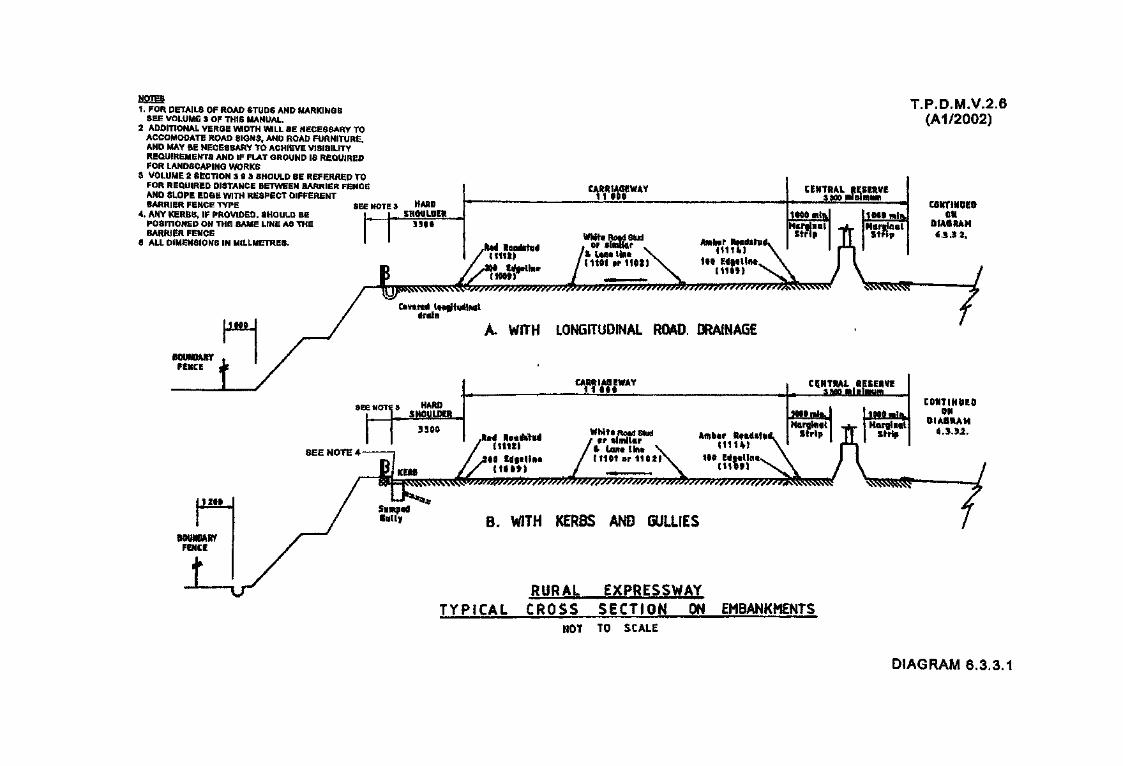
NOTES1. FOR DETAILS OF ROAD STUDS AND MARKINGS
SEE VOLUME S OF THIS MANUAL.2 ADDITIONAL VERGE WIDTH WILL BE NECESSARY TO
ACCOMODATE ROAD SIGNS, AND ROAD FURNITURE.AND MAY BE NECESSARY TO ACHIEVE VISIBILITYREQUIREMENTS AND IF FLAT GROUND IS REQUIREDFOR LANDSCAPING WORKS
3 VOLUME 2 SECTION 3 9 S SHOULD BE REFERRED TOFOR REQUIRED DISTANCE BETWEEN BARRIER FENCEAND SLOPE EDGE WITH RESPECT DIFFERENTBARRIER FENCE TYPE SEE NOTE 3
4. ANY KERBS, IF PROVIDED, SHOULD BEPOSITIONED ON THE SAME LINE AS THEBARRIER FENCE
9 ALL DIMENSIONS IN MtLLMETRES.
T.P.D.M.V.2.6(A1/2002)
seuuBftBirFENCE
tfraiit
A. WITH LONGITUDINAL ROAD. DRAINAGE
SEE NOTE: 4It1«t«r1ietl">ai
StffltpaaInlly B. WITH AND
RURAL EXPRESSWAYTYPICAL CROSS SECTION ON EMBANKMENTS
NOT TO SCALE
DIAGRAM 6.3.3.1
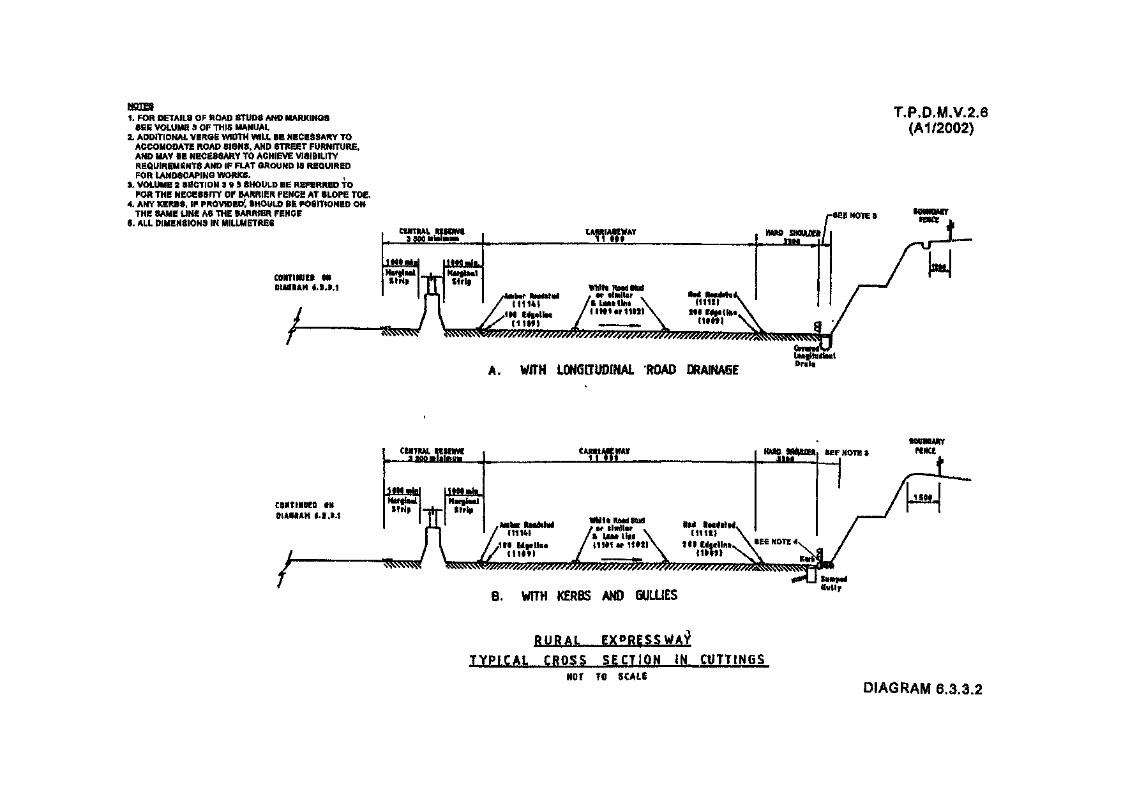
1. FOR DETAILS OF ROAD STUDS AND MARKINGSSEE VOLUME 3 OF THIS MANUAL
2. ADDITIONAL VERGE WIDTH WILL BE NECESSARY TOACCOMODATE ROAD SI0N8, AND STREET FURNITURE,AND MAY BE NECESSARY TO ACHIEVE VISIBILITYREQUIREMENTS AND IF FLAT GROUND IS REQUIREDFOR LANDSCAPING WORKS.
5. VOLUME 2 SECTION 3 « 3 SHOULD BE REFERRED TOFOR THE NECESSITY OF BARRIER FENCE AT SLOPE TOE.
4. ANY KERBS, IF PROVIDED', SHOULD BE POSITIONED ONTHE SAME LINE AS THE BARRIER FENCE
6. ALL DIMENSIONS IN MILLIMETRES
c&iiTiifut& mOIASBAH i.S.1.1
TP.D.M.V.2.6(A1/2002)
CEMTfiAL HHSClWgg 30»Q atel»ia»^
Hsftrflifii a NflfBift&t
ttrip "nr strt?
" fes SSf \^^s^
CIMUIUplh.
A. WITH
CIHTf l I
Strip Strip
CAMI,twmwf
SEF NOTE $ pe^«
/ / & ISM llSi \ \/,1li l pllRs / |1fd1»1i«l\ HI Mftllntv \SE
^LJZ«^/L^aa^^.SEE NOTE 4
8. WITH AND 6ULUESSwity
^NOT TO SCALE
DIAGRAM 6.3.3.2

1. FOR DETAILS OF ROAD STUDS AND MARKINGSSEE VOLUME 3 OF THIS MANUAL.
2. ADDITIONAL VERGE WIDTH WILL BE NECESSARY TOACCOMODATE ROAP SIGNS, AND ROAD FURNITURE.AND MAY BE NECESSARY TO ACHIEVE VISIBILITYREQUIREMENTS AND IF FLAT GROUND IS REQUIREDFOR LANDSCAPING WORKS.
3. VOLUME 2 SECTION 3.9.3 SHOULD BE REFERRED TOFOR REQUIRED DISTANCE BETWEEN BARRIER FENCEAND SLOPE EDGE WITH RESPECT DIFFERENTBARRIER FENCE TYPE.
4. ANY KERBS, IF PROVIDED, SHOULD BEPOSITIONED ON THE SAME LINE AS THEBARRIER FENCE.
6. ALL DIMENSIONS IN MILLMETRES.
T.P.D.M.V.2.(A1/2002)
CMRIJMWAY11900
Whirl HOStJSfUCt
Sw»5v^^^ '>^^
SUHPGJ sjiBf o* OSJYOTJ uaemsHa. mm WTTKSUT tee/ioxmNS ra CRCOHSI C^
A. WHERE L0CAL OFHCULTES H«V£NT A FULL HARD SHOULDB? FROM6SNS PROVDE)
W ^ w ' ' » * > f t m w u » t t f f
Covirtd longthidM <Mn
B. TO BE USED M EXCEFTIONAL CROJMSTANCES ONLY(NORMALLY ONLY APPLICABLE IN RESPECT OF EXISTING CARRIAGEWAYS)
RURAL EXPRESSWy CROSS SECTION WHERE FULL HARD SHOULDERS CANNOT BE PRQvinmNOT 10 SCALE
DIAGRAM 6.3.3.3

1. FOR DETAILS OF ROAD STUDS AND MARKINGSSEE VOLUME 3 OF THIS MANUAL.
2. ADDITIONAL VERGE WIDTH WILL BE NECESSARY TOACCOMODATE ROAD SIGNS, AND ROAD FURNITURE,AND MAY BE NECESSARY TO ACHIEVE VISIBILITYREQUIREMENTS AND IF FLAT GROUND IS REQUIREDFOR LANDSCAPING WORKS
3. VOLUME 2 SECTION 3.0 3 SHOULD BE REFERRED TOFOR REQUIRED DISTANCE BETWEEN BARRIER FENCEAND SLOPE EDGE WITH RESPECT DIFFERENTBARRIER FENCE TYPE. j
4. ANY KERBS, IF PROVIDED, SHOULD BEPOSITIONED ON THE SAME LINE AS THEBARRIER FENCE.
5. ALL DIMENSIONS IN MILLMETRES.
T.P.D.M.V.2.6(Al/2002)
BOUNDARYFEHCE
CARRIAGEWAY.1 1 0 » 0
Whits Road Stud«f similar
& UBft lineAm&tr
C11U1
RESERVE
A «$-
A, WITH LONGITUDINAL ROAD
CEHTRALRfSEHVI
Lane line{1111 er 1102TIfffiline
9 @ f }
i ^^^^fpS?^^^^^9i~K^
B. WITH AND GULLIESSttm&tdiotlf
NOT TO SCALE
7
CONTtHUEO ON
DIAGRAM 6.3.3.4

T.P.D.M.V.2.6(A1/2002)
CONTimiED ONDIAGRAM f.3.1.4.
CENTRALRESERVE 1
Jl W mta,™
B
CARRIAGEWAY ,r-r-—- 11 80S
White Road Stud/Anther teatfftiHi y or similar v Retf ReKdsfytL/ 111141 /*UB*tiii« \ 11112) A
ftASOSHOUUJCR riEE NOTE 3
•/•C1109I IfOtfl \>
NOTES
1. FOR DETAILS OF ROAD STUDS AND MARKINGSSEE VOLUME 3 OF THIS MANUAL.
2. ADDITIONAL VERGE WIDTH WILL BE NECESSARYTO ACCOMODATE ROAD SIGNS, AND STREETFURNITURE, AND MAY BE NECESSARY TOACHIEVE VISIBILITY REQUIREMENTS ANDIF FLAT GROUND IS REQUIRED FORLANDSCAPING WORKS.
3. VOLUME 2 SECTION 3.0.3 SHOULD BEREFERRED TO FOR THE NECESSITY OFBARRIER FENCE AT SLOPE TOE.
4. ANY KERBS, IF PROVIDED, SHOULD BEPOSITIONED,ON THE SAME LINE AS THEBARRIER FENCE.
a. ALL DIMENSIONS IN MILLIMETRES. -
CONTINUED Oft
OIA6HAH «.3.S.&.
A.
y^^^/^/77^^^^^
WJTH LOGITUDINAL ROAD DRAINAGE
BOUNDARYFENCE
/KERBS AND GULLIES
gutty
URBAN EXPRESSWAY
T Y P I C A L CROSS SECTION IN CUTTINGSNOT TO SCALE
DIAGRAM 6.3.3.6

PARAPET FORMSBOUNDARY OFEXPRESSWAY.
T.P.D.M.V.2.
(A1/2002)PARAPET FORMSBOUNDARY OFEXPRESSWAY
URBAN OR RURAL S ITUATION
NOTES
1. FOR DETAILS OF ROAD STUDS ANDMARKINGS SEE VOLUME S<
I. 5RAINA6E ON ELEVATED SECTIONSWILL NORMALLY BE BY SUMPEB GULLIESLOCATED AT THE BACK OF THE HARD
NOT TO SCALE
3. WIDENING HAY BE NECESSARY TOACCOHOOATE mm SIGNS AND STREETFUmiTURE AND TO ACWEVE VISWUTYRG®tfll!0€NTS,
4. ALL mmmm m
DIAGRAM 6,3,3.6
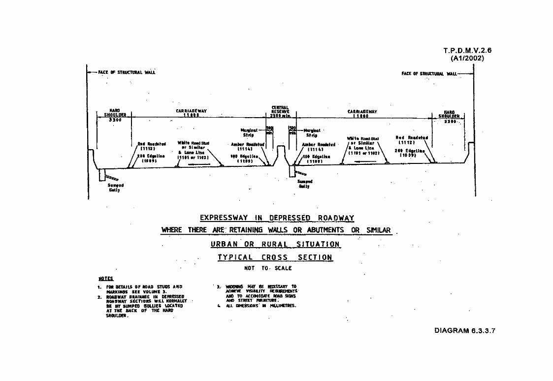
T.P.D.M.V.2.6(A1/2002)
•FACE OF STRUCTURAL WALL FACE OF STRUCTURAL WALL-
SumpedGtttty
EXPRESSWAY IN DEPRESSED ROADWAY
WHERE THERE ARE RETAINING WALLS OR ABUTMENTS OR SIMILAR
URBAN OR RURAL SITUATION
T Y P I C A L CROSS SECTION
NOT TO- SCALE
NOTES
1. FOB DETAILS OF ROAD STUDS ANDHARKINSS SEE VOLUME 5.
2. ROADWAY DRAINAGE IK DEPRESS KBROADWAY SECTIONS WILL NORMALLY8E BY SUMPED SULUES LOCATEDAT THE SACK OF THE HAROSHOULDER.
B, WtODtfNS MAY BE I€CESSARY TOACHIEVE VtSlSSUTY ICQUREMEHTSM& TO ACCOMODATE ftQAO SIONSAND STREET RJRHITUBE.
4 ALL CKfCHSKlHS IN MILLIMETRES.
DIAGRAM 6.3.3.7

T.P.D.M.V.2.6
HARD SHOULDER3300
CARRIAGEWAY4000 (SINGLE LANE)7300 (TWO LANE)
MARGISTRIP1000
HAL
rREDROADSTUD
(1112)
200 EDGEUNE(1009)
AMBER
100 EQGELINE(110»
SUHPEOBULLEY
EXPRESSWAY LINK ROAD
DEPRESSED OR ELEVATED
TYPICAL CROSS SECTION. NOT TO SCALE
-FACE OF STRUCTURAL VflLLW DEPRESSED ROADS
NOTES;
1.POR SETAtS CF RQADSTUDS AND MARKWQSSEE VOLUME 3.
2.DRAINAGE ON ELEWEO OR DEPRESSEDSECTIONS WLL NORMALLY BE BY SUHPEOGULLIES LOCATED AT THE BACK OFTHE HARD SHOULDER.
3.THE MARGINAL STWP HAY BE REDUCEDTO NOT LESS THAN SOOhim FOR2-LANE URBAN EXPRESSWAY LINKROADS WHERE LOCAL DIFFICULTIESEXIST.
4.WDENMG MAY BE NECESSARY TOACCONOPATE ROAD SIGNS AND STREETFURNITURE AND TO ACHIEVE VtSIBUTYREQUIREMENTS.
5.ALL DMENSIONS M MILLIMETRES,
DIAGRAM 6.3.3.8
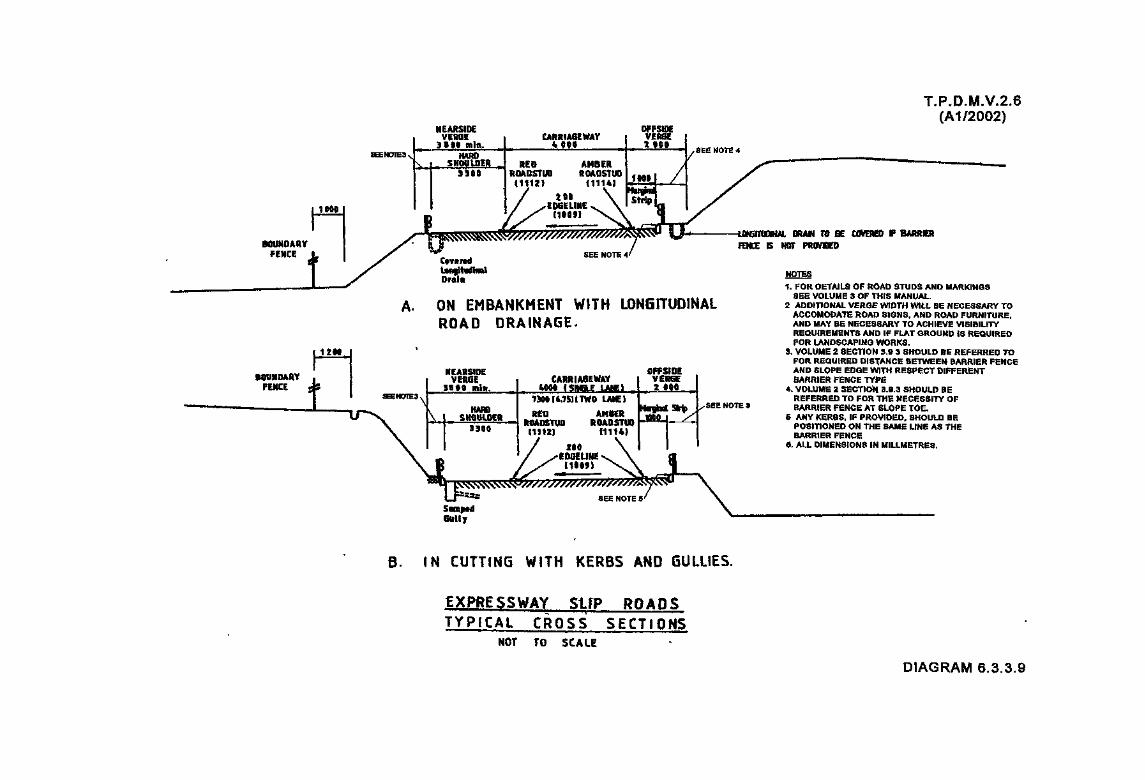
T.P.D.M.V.2.6(A1/2002)
10&Q
BOUMQA8YFENCE
1
1290
38UNQARYFENCE 1
NEARSIDEVERSE
3869 min. ^IE3N HARD
v cHnuif}£&3SBO Rl
1
>r JL^
OFFSIDICARRIA6EWAY VERSE
4«0« 3ii 2900
RED AMBER3ADSTUO ROADSTUO <afift •1115^ fin&! JLZ£U,« /
/ »H \ S^^ ^EDSELINE s. \ mpklX "••" N^ J,
/ /" ~ ~~
JrJ*$a^^^g^//////////M/MS/S/Ss!^** 1U- UJNWiUWKAl UHAW IU fcfc UHfltHikl* if WWW
S LJ / ra*2 * m pRoveeo^ . SEE NOTE 4'
Covered
aa?*" •«»1. FOR DETAILS OF ROAD STUDS AND MARKINGS
SEE VOLUME 3 OF THIS MANUALA. ON EMBANKMENT WITH LONGITUDINAL 2 ADDITIONAL VERGE WIDTH WILL BE NECESSARY TO
* * * * * » «L A in * *~ t» ACCOMODATE ROAD SIGNS, AND ROAD FURNITURE,ROAD u R A I N A u t • AND MAY BE NECESSARY TO ACHIEVE VISIBILITY
REQUIREMENTS AND IF FLAT GROUND IS REQUIREDFOR LANDSCAPING WORKS.
3. VOLUME 2 SECTION 3.9 3 SHOULD BE REFERRED TOFOR REQUIRED DISTANCE BETWEEN BARRIER FENCE
NEARSIDE OFFSIOE AND SLOPE EDGE WITH RESPECT DIFFERENTVERGE * CARRIAGEWAY VERSE BARRIER FENCE TYPE
3S 60 mitt. 4009 fSIIS.E LAt€l , 2r tM, „ * VOLUME 2 SECTION 3 ,fl,3 SHOW D RF'NCfIE3^
\ HAm\ SHOULDER
3966
\7^{6.7§HTWO LANE)
RED AMdEft J^^ !
ft&MISYUD ROAD5TIJQ "*" •"H1I2J 11114)
/ *•• \/ v'EDSELIIISx^ \ d//^jmf^ \s\ J
™r ? ^^Lj 23* SEE NOTE 5/
Semp*dS«Uy
1. IN CUTTING WITH KERBS AND 1
EXPRESSWAY SUP ROAD!
TYPICAL
REFERRED TO FOR THE NECESSITY OFg , /SEE NOTE 3 BARRIER FENCE AT SLOPE TbE./ 6 ANY KERBS, IF PROVIDED, SHOULD BE
POSITIONED ON THE SAME LINE AS THEBARRIER FENCE
6. ALL DIMENSIONS IN MILLMETRES.
SULLIES.
»
C R O S S SECTIONS
MOT TO SCALE
DIAGRAM 6.3.3.9

mmwt
SEE NOTE 4
T.P.D.M.V.2.6(A1/2002)
1 FOR DETAILS OF ROAD STUDS AND MARKINGSSEE VOLUME 3 OF THIS MANUAL
2 ADDITIONAL VERGE WIDTH WILL BE NECESSARYTO ACCOMODATE ROAD SIGNS, AND STREETFURNITURE, AND MAY BE NECESSARY TOACHIEVE VISIBILITY REQUIREMENTS
3. ADDITIONAL VERGE WIDENING FOR LANDSCAPINGIS NOT ACCEPTABLE IF FULL WIDTH HARDSHOULDERS CANNOT BE PROVIDED
4. VOLUME 2 SECTION 3 9 3 SHOULD BE REFERREDTO FOR REQUIRED DISTANCE BETWEEN BARRIERFENCE AND SLOPE EDGE WITH RESPECTDIFFERENT BARRIER FENCE TYPE
8. VOLUME 2 SECTION 3 6.3 SHOULD BEREFERRED TO FOR THE NECESSITY OFBARRIER FENCE AT SLOPE TOE.
6 ANY KERBS, IF PROVIDED, SHOULD BEPOSITIONED ON THE SAME LINE AS THEBARRIER FENCE
7. ALL DIMENSIONS IN MILLMETRES
(A) LOCAL A FULL HARD FROH
SHPULD ggIS NOT
IB) TO BE USED IN EXCEPTIONAL CIRCUMSTANCES ONLY
EXPRESSWAY SUP FULL HARD BE
DIAGRAM 6.3.3.10

T.RD.M.V.2.6(Al/2002)
v) earth mounding;
vi) kerbs or raised kerbs;
vii) open drainage channels; and
viii) police observation platform.
6.3.3.8 It is most desirable that the standard 3300mm hard shoulder width is maintained throughoutthe Expressway Network. However whenever this is not possible, this may be reduced to3000mm, as shown in Diagrams 6.3.3.3 and 6.3.3.10 to meet local difficulties for both ruraland urban conditions. Any reduction below 3000mm, and never to less than 2500mm, onthe main line, including any link roads, will only be permitted in extenuating circumstancesand a full justification will be required as to why such reduction is necessary. Cost aloneshould not be regarded as sufficient justification in this respect.
6.3.3.9 In 'Bf in Diagram 6.3.3.10, along slip roads the provision of a marginal strip only may beacceptable, generally in urban conditions, where exceptional situations prevail which makesthe provision of a shoulder or full hard shoulder highly impractical. In such circumstancesa full justification of why only a nearside marginal strip can be provided must be given.
6.3.3.10 Where, as in Diagrams 6.3.3.3 and 6.3.3.10, the shoulder consists of a hardened verge, thisverge should only be grassed, preferably with height not more than 200mm, but in any casenot taller than 300mm. Ground cover plants with sprawling habit such as WedeliaTrilobata1 must not be used at hardened verges.
6.3.3.11 The cross sections shown are for typical situations and extra width may be necessary wherefor instance, the carriageway crossfall reverses and additional drainage channels are therebyrequired. Also the central reserve widths are minimal and if for example traffic signs,other than repeater signs, are required to be erected on the central reserve, which will needto be of the 1200mm size, to obtain the normal clearances of 1000mm for this type of road areserve width of 3200mm will be required. For isolated signs in extenuating circumstancesthis may be reduced, but the clearance between the sign and the edge of the carriagewayshould never be less than 600mm, which implies a central reserve width of at least 2400mm.
6.3.3.12 Additionally as mentioned in paragraph 6.3.3.2 the cross sections do not allow for theprovision of road side signs; any visibility splays which might be required; and landscaping.For these latter elements additional land will be required. If lighting columns are locatedon the nearside of the road due to whatever reason, additional land will be required and abarrier fence should be provided as a protection for the columns. This is particularlyrelevant to slip roads and link roads, where often road lighting columns will need to belocated on the nearside.
6.3.3.13 Where only a marginal strip is provided along a slip road the taper in respect of thewidening to or from the hard shoulder provided along the main route should be inaccordance with Diagram 6.3.3.11.

MARGNAL STRIPTO HARD SHOULDER
TAPES. 1:30 .. i . HOSE
MERGE LANE
HARD SHOULDERTO MARGINAL STRIP
NOSE TAPER
DIVERGE LANE
MARGINAL STRIP TOHARD SHOULDER TAPERS
T.P.D.M.V.2.6
DIAGRAM 6.3.3.11

T.RD.M.V.2.6(Al/2002)
6.3,4 Drainage CoBsiderations
6.3.4.1 Where longitudinal road drainage of the slotted channel type is to be used, and this isparticularly preferable in flat terrain, the covers of the slotted channels should be laid at therear of the hard shoulder.
6.3.4.2 Where drainage is required the kerb should be laid at the rear of the hard shoulder, withgullies located adjacent to the kerb.
6.3.4.3 Wherever manhole covers are provided, they should be located in the hard shoulder orpreferably in the verge beyond this. This implies that the road pavement drainage carrierdrains should also be located beneath the hard shoulder or verge but where this is notpossible the manhole access shaft and hence the manhole cover should be located within thehard shoulder or as near to it as possible. Heavy duty manhole covers should always beused, even where they are located within the verge or hard shoulder.
6.3.4.4 Any longitudinal drains placed at or within 3m of the rear of the shoulder should be covered,where for any reasons this is not possible or not desirable from a maintenance point of view,a barrier fence must be erected in front of the drain.
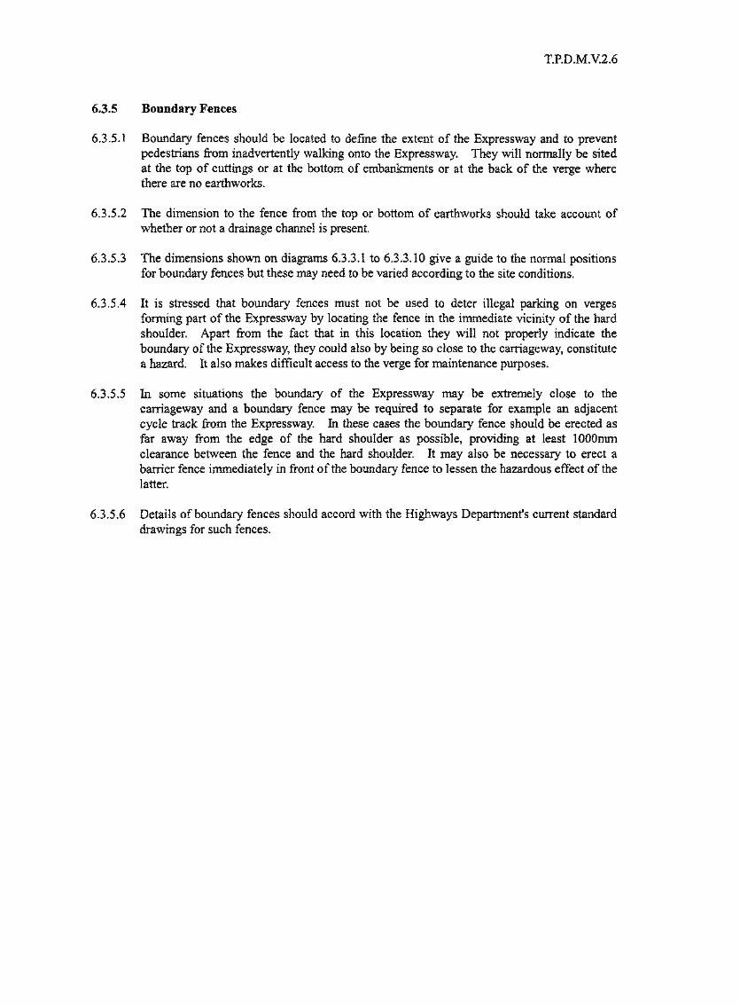
T.RD.M.V.2.6
63.5 Boundary Fences
6.3.5.1 Boundary fences should be located to define the extent of the Expressway and to preventpedestrians from inadvertently walking onto the Expressway. They will normally be sitedat the top of cuttings or at the bottom of embankments or at the back of the verge wherethere are no earthworks.
6.3.5.2 The dimension to the fence from the top or bottom of earthworks should take account ofwhether or not a drainage channel is present.
6.3.5.3 The dimensions shown on diagrams 6.3.3.1 to 6.33.10 give a guide to the normal positionsfor boundary fences but these may need to be varied according to the site conditions.
6.3.5.4 It is stressed that boundary fences must not be used to deter illegal parking on vergesforming part of the Expressway by locating the fence in the immediate vicinity of the hardshoulder. Apart from the fact that in this location they will not properly indicate theboundary of the Expressway, they could also by being so close to the carriageway, constitutea hazard. It also makes difficult access to the verge for maintenance purposes.
6.3.5.5 In some situations the boundary of the Expressway may be extremely close to thecarriageway and a boundary fence may be required to separate for example an adjacentcycle track from the Expressway. In these cases the boundary fence should be erected asfar away from the edge of the hard shoulder as possible, providing at least 1000mmclearance between the fence and the hard shoulder. It may also be necessary to erect abarrier fence immediately in front of the boundary fence to lessen the hazardous effect of thelatter.
63.5.6 Details of boundary fences should accord with the Highways Department's current standarddrawings for such fences.

T.RD.M. V.2.6(Al/2002)
63.6 Junctions
6.3.6.1 Junctions on Expressways will always be grade separated. Detailed requirements for thelayout of grade separated junctions are given in Section 4.6 of Chapter 4 of this Volume.
6.3.6.2 Junctions on Expressways should preferably be spaced at about 5km intervals but wherecircumstances require a closer spacing, this should not be reduced to below 2km.
6.3.6.3 New junctions giving access onto an existing Expressway should only be permitted to allowan extension of the Expressway system or to link a primary distributor road to anExpressway. Junctions or accesses, even when provided with full acceleration anddeceleration lanes, just to serve adjacent developments, however large, should not bepermitted. Such developments should be connected via the minor road network to theExpressway by means of an existing junction.
6.3.6.4 Where it is essential to adopt a close spacing for junctions, particular attention must be paidto the weaving length between the end of the merge taper and the start of the diverge taper,as detailed in Section 4.6.10 of Chapter 4 this Volume.
6.3.6.5 Junctions should be designed with the minor road crossing over the major road so that entryslip road gradients are down towards the major road of the Expressway and exit slip roadsare up away from the major road of the Expressway. This aids the acceleration of vehiclesentering the Expressway and likewise assists their deceleration as they leave.
6.3.6.6 Where large traffic flows with nearly full capacity are joining the mainline in an interchangeor junction, turbulence can occur with short headways and sudden braking. A parallelmerge lane should be provided to increase local capacity.
6.3.6.7 If the joining flows are greater than one lane capacity then an additional lane shouldnormally be added to the mainline as a lane gain.
6.3.6.8 Any queueing back to rejoin the local network to impede the mainline traffic should beprevented by providing an auxiliary lane.
6.3.6.9 Whilst it may be possible to justify lane drops within grade separated junctions on capacitygrounds, the number of lanes through the junction should not be reduced to less than threeand lane drops should not differ by more than one. Furthermore, the ExpresswayLegislation requires drivers 'to keep to the left unless overtaking' and thus lane drops willnecessitate additional signing and marking. Advice on this is included in Chapters 2 and 5respectively of Volume 3.
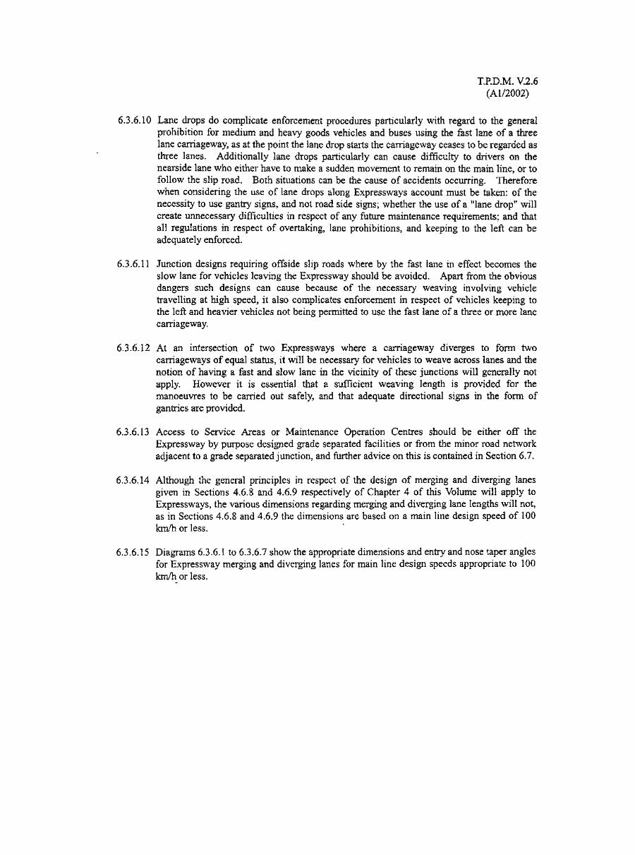
T.RD.M. V.2.6(Al/2002)
6.3.6.10 Lane drops do complicate enforcement procedures particularly with regard to the generalprohibition for medium and heavy goods vehicles and buses using the fast lane of a threelane carriageway, as at the point the lane drop starts the carriageway ceases to be regarded asthree lanes. Additionally lane drops particularly can cause difficulty to drivers on thenearside lane who either have to make a sudden movement to remain on the main line, or tofollow the slip road. Both situations can be the cause of accidents occurring. Thereforewhen considering the use of lane drops along Expressways account must be taken: of thenecessity to use gantry signs, and not road side signs; whether the use of a "lane drop" willcreate unnecessary difficulties in respect of any future maintenance requirements; and thatall regulations in respect of overtaking, lane prohibitions, and keeping to the left can beadequately enforced.
6.3.6.11 Junction designs requiring offside slip roads where by the fast lane in effect becomes theslow lane for vehicles leaving the Expressway should be avoided. Apart from the obviousdangers such designs can cause because of the necessary weaving involving vehicletravelling at high speed, it also complicates enforcement in respect of vehicles keeping tothe left and heavier vehicles not being permitted to use the fast lane of a three or more lanecarriageway.
6.3.6.12 At an intersection of two Expressways where a carriageway diverges to form twocarriageways of equal status, it will be necessary for vehicles to weave across lanes and thenotion of having a fast and slow lane in the vicinity of these junctions will generally notapply. However it is essential that a sufficient weaving length is provided for themanoeuvres to be carried out safely, and that adequate directional signs in the form ofgantries are provided.
6.3.6.13 Access to Service Areas or Maintenance Operation Centres should be either off theExpressway by purpose designed grade separated facilities or from the minor road networkadjacent to a grade separated junction, and further advice on this is contained in Section 6.7.
6.3.6.14 Although the general principles in respect of the design of merging and diverging lanesgiven in Sections 4.6.8 and 4.6.9 respectively of Chapter 4 of this Volume will apply toExpressways, the various dimensions regarding merging and diverging lane lengths will not,as in Sections 4.6.8 and 4.6.9 the dimensions are based on a main line design speed of 100km/h or less.
6.3.6.15 Diagrams 6.3.6.1 to 6.3.6.7 show the appropriate dimensions and entry and nose taper anglesfor Expressway merging and diverging lanes for main line design speeds appropriate to 100km/h or less.
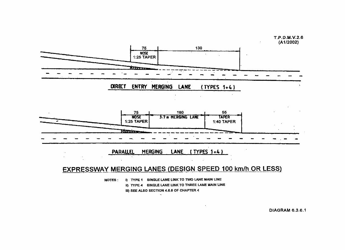
T.P.D.M.V.2.6(A172002)
DIRECT ENTRY HERGING LANE (TYPES U4)
553.7 ffl MERGING LANE
PARAliEL MERGING LANE (TYPES 1 *4)
EXPRESSWAY MERGING LANES (DESIGN SPEED 100 km/h OR LESS)
NOTES : i) TYPE 1 SINGLE LANE LINK TO TWO LANE MAIN LINE
if) TYPE 4 SINGLE LANE LINK TO THREE LANE MAIN LINE
Hi) SEE ALSO SECTION 4.6.8 OF CHAPTER 4
DIAGRAM 6.3.6.1

T.P.D.M.V.2.6(A172002)
130
SHADOW tSUND MERGING LANE (TYPES 2+5)
EXPRESSWAY MERGING LANES (DESIGN SPEED 100 km/h OR LESS)
NOTES: i) TYPE a TWO LANE LINK TO TWO LANE MAIN LINE
II) TYPE 5 TWO LANE LINK TO THREE LANE MAIN LINE
III) SEE ALSO SECTION 4.6.8 OF CHAPTER 4
iv) ONLY USED WHERE DESIGN FLOWS ON MAINLINE ARE LIGHTAND THERE ARE 3 LANES OR MORE ON MAINLINE
DIAGRAM 6.3.6.2

MIN. LANEWIDTH 3.7m
ISLAND WIDTH2m MIN. AT
WIDEST POINT
T.P.D.M.V.2.(A1/2002)
150
MIN. LANEWIDTH 3.7m
SHADOW ISLANDWIDTH 2m MIN.
AT WIDEST POINT
SHADOW UW£ fTYPES 3*6)
EXPRESSWAY (DESIGN 100 km/h OR
NOTES : i) TYPE 3 TWO LANE LINK, MAIN LINE TWO INCREASING TO THREE
li) TYPE 6 TWO LANE LINK, MAIN LINE THREE INCREASING TO FOUR
iii) SEE ALSO SECTION 4.6.8 OF CHAPTER 4
DIAGRAM 6.3.6.3
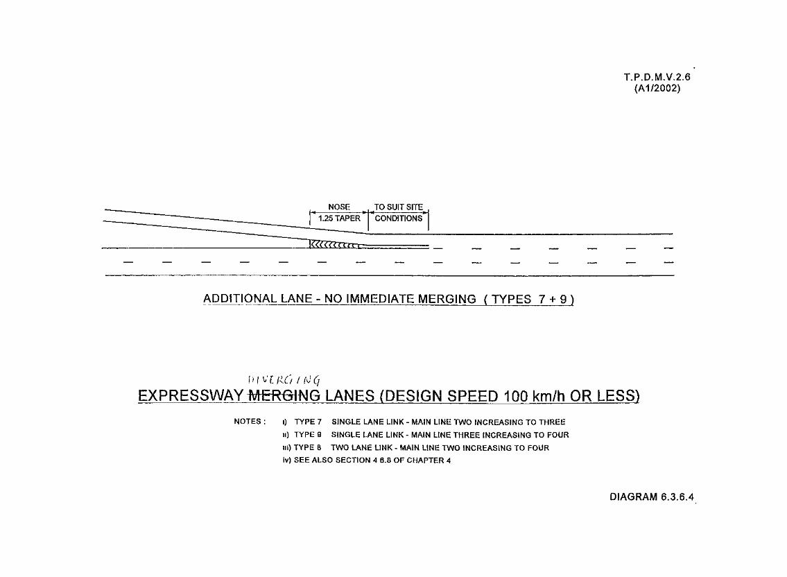
T.P.D.M.V.2.6(A1/2002)
NOSE TO SUIT SITE
ADDITIONAL LANE-NO IMMEDIATE MERGING (TYPES 7 + 9)
EXPRESSWAY MERGING LANES (DESIGN SPEED 100 km/h OR LESS)
NOTES : i) TYPE 7 SINGLE LANE LINK - MAIN LINE TWO INCREASING TO THREE
n) TYPE 9 SINGLE LANE LINK - MAIN LINE THREE INCREASING TO FOUR
in) TYPE 8 TWO LANE LINK - MAIN LINE TWO INCREASING TO FOUR
Iv) SEE ALSO SECTION 4 6.8 OF CHAPTER 4
DIAGRAM 6.3.6.4

T.P.D.M.V.2.6(A172002)
70 NOSE
DIRECT DIVERGING LANE ( TYPES 1 + 3 )
70 NOSE
PARALLEL DIVERGING LANE ( TYPES 1 + 3 )
EXPRESSWAY DIVERGING LANES (DESIGN SPEED 100 km/h OR LESS)
NOTES : i) TYPE 1 ONE LANE LINK FROM TWO LANE MAIN LINE
ii) TYPE 3 ONE LANE LINK FROM THREE LANE MAIN LINE
iii) SEE ALSO SECTION 4.6.9 OF CHAPTER 4
DIAGRAM 6.3.6.5
T.P.D.M.V.2.6(A1/2002)
70 NOSE
DIRECT DIVERGING LANES ( TYPES 2 + 5 )
110 150 70 NOSE
PARALLEL DIVERGING LANES ( TYPES 2 + 5 )
EXPRESSWAY DIVERGING LANES (DESIGN SPEED 100 km/h OR LESS)
NOTES I) TYPE 2 TWO LANE LINK FROM TWO LANE MAIN LINE
ii) TYPE 5 TWO LANE LINK FROM THREE LANE MAIN LINE
in) SEE ALSO SECTION 4 6 9 OF CHAPTER 4
DIAGRAM 6.3.6.6

T.P.D.M.V.2.6(A1/2002)
130 70 NOSE
DIRECT DIVERGING LANES ( TYPES 4 + 6)
PARALLEL DIVERGING LANES ( TYPES 4 + 6 )
EXPRESSWAY DIVERGING LANES (DESIGN SPEED 100 km/h OR LESS)
NOTES : i) TYPE 4 TWO LANE LINK - MAIN LINE THREE LANES DECREASING TO TWO LANES
ii) TYPE 6 TWO LANE LINK - MAIN LINE FOUR LANES DECREASING TO THREE LANES
Hi) SEE ALSO SECTION 4.6.9 OF CHAPTER 4
DIAGRAM 6.3.6.7
T.RD.M.V.2.6
6.3.7 Access
6.3.7.1 Access to and from any Expressway should be provided only at the regularly spaced gradeseparated junctions, as access at any other location should be prohibited. Direct access offslip roads, which must be regarded as an integral part of an Expressway, should not for anyreason be permitted.
6.3.7.2 Intermediate access, for whatever purpose, must not be allowed, and the boundary fencemust be regularly maintained to ensure that no illegal accesses are created,
6.3.7.3 Before a road can be designated as an Expressway any existing unauthorised accesses mustbe effectively curtailed and physically closed up. The same applies to any authorisedaccesses, such as, entrances/exits from service roads, bus stops, or similar, which must beremoved and/or relocated away from the Expressway before the road may be considered asan Expressway.
6.3.7.4 Pedestrians and animals are prohibited from using any Expressway. However following avehicle breakdown, a driver is permitted to walk along the verge or hard shoulder to reachthe nearest emergency telephone and thus the verge should be designed with this in mind, todiscourage the driver from walking on the carriageway.
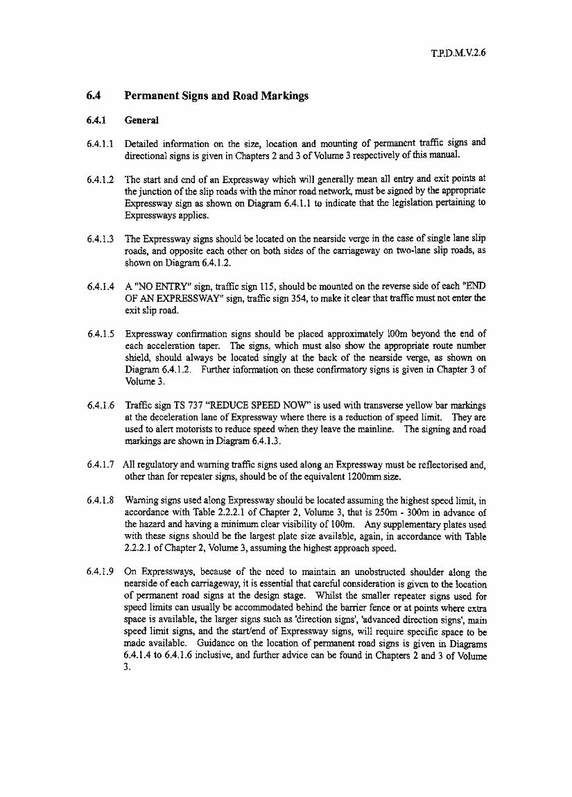
T.RD.M.V.2.6
6.4 Permanent Signs and Road Markings
6.4.1 General
6.4.1.1 Detailed information on the size, location and mounting of permanent traffic signs anddirectional signs is given in Chapters 2 and 3 of Volume 3 respectively of this manual.
6.4.1.2 The start and end of an Expressway which will generally mean all entry and exit points atthe junction of the slip roads with the minor road network, must be signed by the appropriateExpressway sign as shown on Diagram 6.4.1.1 to indicate that the legislation pertaining toExpressways applies.
6.4.1.3 The Expressway signs should be located on the nearside verge in the case of single lane sliproads, and opposite each other on both sides of the carriageway on two-lane slip roads, asshown on Diagram 6A.I.2.
6.4.1.4 A "NO ENTRY" sign, traffic sign 115, should be mounted on the reverse side of each "ENDOF AN EXPRESSWAY" sign, traffic sign 354, to make it clear that traffic must not enter theexit slip road.
6.4.1.5 Expressway confirmation signs should be placed approximately 100m beyond the end ofeach acceleration taper. The signs, which must also show the appropriate route numbershield, should always be located singly at the back of the nearside verge, as shown onDiagram 6.4.1.2. Further information on these confirmatory signs is given in Chapter 3 ofVolume3.
6.4.1.6 Traffic sign TS 737 "REDUCE SPEED NOW" is used with transverse yellow bar markingsat the deceleration lane of Expressway where there is a reduction of speed limit. They areused to alert motorists to reduce speed when they leave the mainline. The signing and roadmarkings are shown in Diagram 6.4.1.3.
6.4.1.7 All regulatory and warning traffic signs used along an Expressway must be reflectorised and,other than for repeater signs, should be of the equivalent 1200mm size.
6.4.1.8 Warning signs used along Expressway should be located assuming the highest speed limit, inaccordance with Table 2.2.2.1 of Chapter 2, Volume 3, that is 250m - 300m in advance ofthe hazard and having a minimum clear visibility of 100m. Any supplementary plates usedwith these signs should be the largest plate size available, again, in accordance with Table2.2.2.1 of Chapter 2, Volume 3, assuming the highest approach speed.
6.4.1.9 On Expressways, because of the need to maintain an unobstructed shoulder along thenearside of each carriageway, it is essential that careful consideration is given to the locationof permanent road signs at the design stage. Whilst the smaller repeater signs used forspeed limits can usually be accommodated behind the barrier fence or at points where extraspace is available, the larger signs such as 'direction signs', 'advanced direction signs', mainspeed limit signs, and the start/end of Expressway signs, will require specific space to bemade available. Guidance on the location of permanent road signs is given in Diagrams6.4.1.4 to 6.4.1.6 inclusive, and further advice can be found in Chapters 2 and 3 of Volume3.
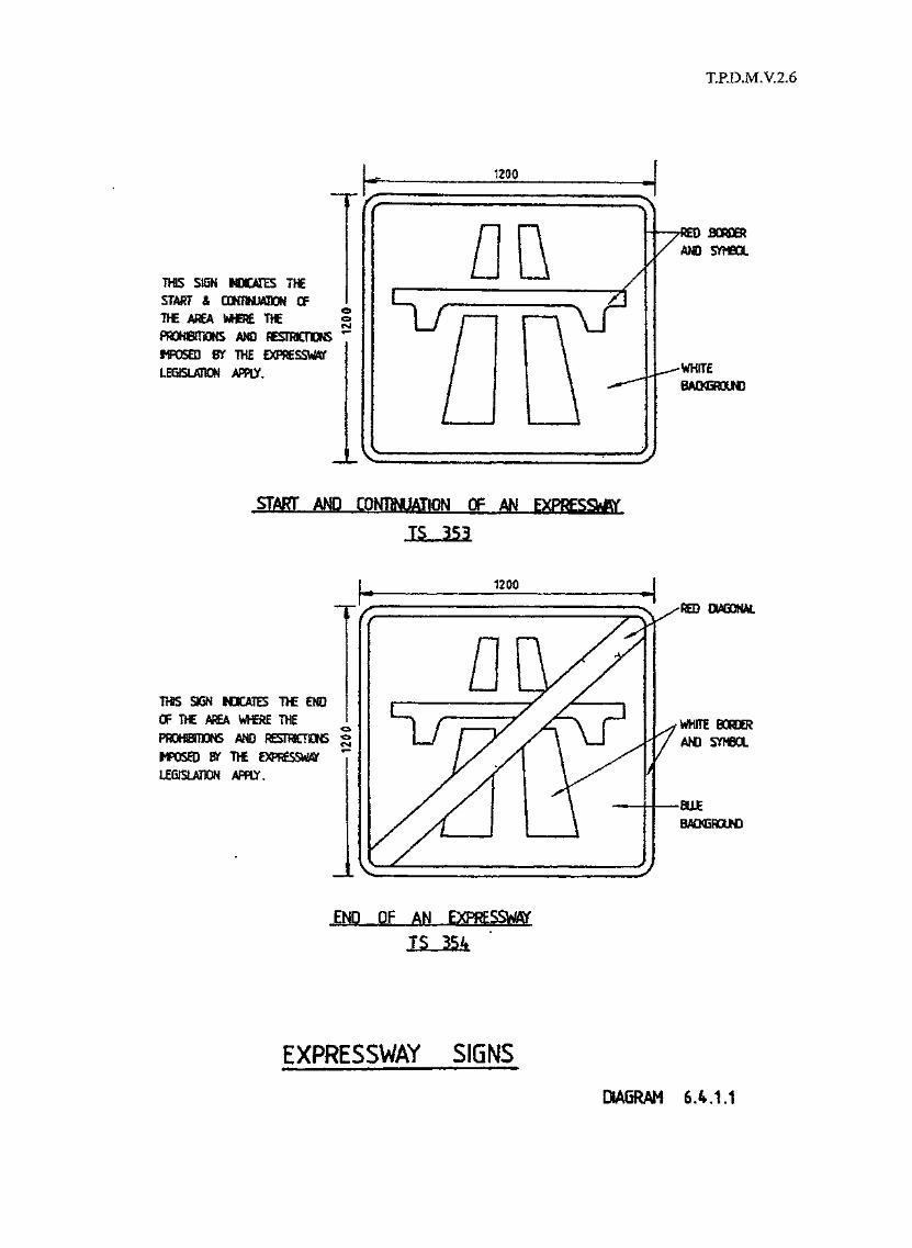
T.RD.M.V.2.6
THIS S1SN INOOXB THE5TAi?T & wmrnm OFTHE AJ€A WHERE THEmxmmS AMDUPOSEQ BT 1>l£LEGISUIK I
oo<SJ
1200
flQ\J \f
BORDER
-WHITE
START AND CQHTMJATION OF AN EXPRESSf
THS SJOH tOCATES T>E EHOOF TW AREA WHERE THE
AND RESTROOISTHEAFRY
B&K5ROUND
END OF AN
TS 354
EXPRESSWAY SIGNS
DIAGRAM 6.4.1,1

T.P.D.M.V.2.6
(Al/2002)
'END OF BPRESSWT
i lFOR 2 LANESUP ROADSI l
HareSORT' AMD 'END SENS SHOULDBE LOCATED ON THE NEARSGEVERGE ON SMGtt LAW SUP ROADS.
ON I LANE SUP ROAOS THEYSHOULD BE LOCATED IN BURSON BOTH SEES OF THE SUP ROAD,
'CQNTHMHON' SIGNS SHOOD AMETSBE LOCATED AT THE BACK OFTHE NEARSGE VERGE.
OMKJWXWAND ROUIE ODNFIRMADGN
LOCATION OF EXPRESSWAY SIGNS
DIAGRAM 6.4.1.2

T.WXM.V. 2.6(A1/2Q02)
DIRECT DIVERGING LANE
Proposed Warning SignTS 737 "Reduce Speed Now"
ModuIeYe I low Bar Markings600 inn Width5000 mn Gap
50m
Existing "50" km/h speed l i m i tsIgns shaII be re Iooated furtherdownstream as far as possible or20m before road bend or junction*subject to adequate sight distance.
PARALLEL DIVERGING LANE
WARNING SIGN AND MARKINGS TO ALERT MOTORISTS TO REDUCE SPEED AT SLIP ROADS
DIAGRAM 6.4.1.3

T.RD.M.V.2.6(Al/2002)
6.4.1.10 Details on the mounting height of traffic signs and directional signs are given in Sections2.2.3 and, 3,2.4, of Chapters 2 and 3, respectively, of Volume 3. However as pedestriansare not allowed on Expressways, the lower range of mounting heights i.e. 900mm - 1500mmwill normally be adopted and, within this range, 900mm is considered to be the safest andmost economic and should be adopted wherever possible, as shown in Diagrams 6.4.1.4 to6A1.6.
6.4.1.11 The use of galvanised steel sections for sign mountings on Expressways is preferred.Fabrication of individual sign mounting components should be completed before galvanisingand the system designed to obviate the need for on site welding, thereby minimising futuremaintenance work.
6.4.1.12 Galvanised sign mountings on Expressways should not be painted. The grey colour of thegalvanised coating is acceptable as a finished colour and any attempt to paint it will incurunnecessary future maintenance requirements and costs.
6.4.1.13 The erection of specific regulatory traffic signs restricting or prohibiting particular actionswill not be necessary providing such restrictions or prohibitions are referred to in therelevant Expressway Legislation. Therefore, for example, traffic signs or road markingsrelating to no stopping will not be required but speed limit signs will. Additionally the useof traffic sign 216, "Hard Shoulder for Emergency Only" is not necessary as it will not bepermitted for vehicles to stop other than in an emergency or to carry out works on any partof the Expressway. The erection of this sign is therefore superfluous and will only createan additional hazard.
6.4.1.14 It is particularly important on Expressways that any signs erected along the route are wellmaintained. Regular inspection and cleaning procedures should therefore be introduced toensure that signs are always legible and do not constitute a hazard because of the need forsome repair.
6.4.1.15 Road markings provide a very necessary guidance for traffic along Expressways and it istherefore essential that any faded or worn markings are replaced, as soon as reasonablypossible, and if necessaiy in advance of any general re-marking programme.
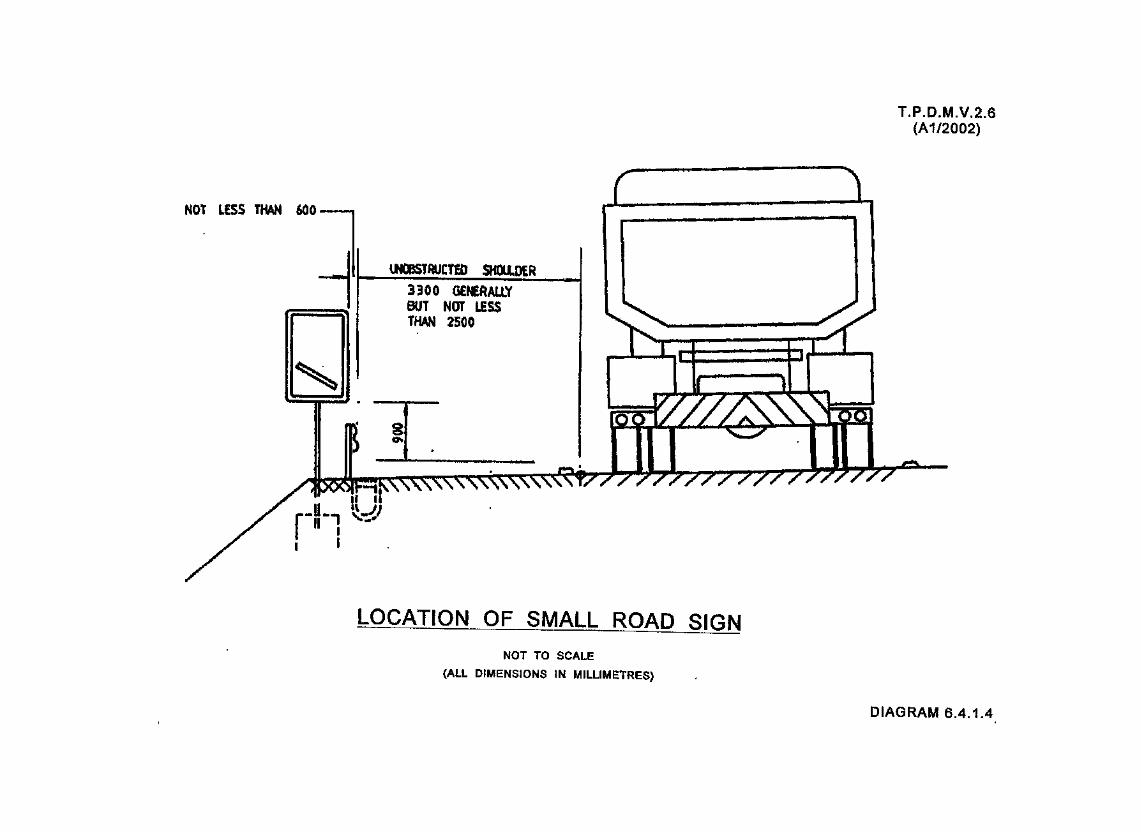


5300NEVCR LESS
THAN 2500
T.P.D.M.V.2.6(A172002)
EMBANKHEWT TOACCDMHQQATE GAMBIT sensuppoirrs
LOCATION OF GANTRY SIGN SUPPORTS
NOT TO SCALE
(ALL DIMENSIONS IN MILLIMETRES)
DIAGRAM 6.4.1.6

T.PD.M.V.2.6(Al/2002)
6.4.2 Directional Signs
6.4.2.1 Details of the design format for directional signs along Expressways are given in Chapter 3of Volume 3, and will be similar to those for Directional Signs along Trunk Roads andPrimary Distributor Roads, except that the background colour of expressway signs should begreen as opposed to blue on non expressway signs. Details of colour of direction signs isgiven in Section 3.2.5 of Volume 3.
6.4.2.2 Along Expressways it is preferable that wherever possible gantry or overhead cantileverdirectional signs are used, with the exception of the signing of service areas where gantrysigns will seldom be justified. Overhead cantilever and roadside directional signs aretherefore appropriate.
6.4.2.3 Where roadside signs are used they will, as mentioned before, require the verge to bewidened to create sufficient space to accommodate the sign structure. The same may applyto gantry and overhead cantilever signs but to a lesser extent. However it is most importantfor all types of signs that allowance for the extra land that may be required is made at thedesign stage, as otherwise the provision of adequate guidance to road users may beprejudiced. The actual width required for this purpose will depend on the particular signbeing used, but for roadside signs, widths of 4000mm or more merely for the sign itself arenot uncommon. The overall space required for the sign will be greater than just the widthof the sign, to allow both, for the necessary clearances, as shown in Diagrams 6.4.1.3 to6.4.1.5 to be achieved, and any working space that may be required around the sign.
6.4.2.4 Although this is a necessity in respect of directional signing for all road types, it is essentialwith regard to Expressways that care is taken to ensure that directional signs are positionedcorrectly in relation to the junction to which they refer, and such that they are clearly visibleto approaching drivers from the appropriate distance. Table 6.4.2,1 provides informationas to the location of signs on Expressways, Table 6.4.2.2 on the minimum clear visibilitydistance requirements, and Diagram 6.4.2.1 illustrates the visibility envelope necessary forroadside signs. Particular care should be exercised in sag curve situations, where a gantrysign may be obscured by another gantry sign or overbridge.
6.4.2.5 Diagram 6.4.2.2 illustrates typical arrangements for gantry and roadside and gantrydirectional signing but further information on this may be found in Chapter 3 of Volume 3,and should be consulted.
6.4.2.6 To avoid the erection of additional structures and to reduce the possibility of signs beingobscured, the use of convenient overbridges should be considered as a possible alternativefor mounting overhead signs but due regard must be given to the suitability of the bridgestructure for this purpose.

T.P.D.M.V.2.6(A1/2002)
MINIMUM CLEAR VISIBILITY DISTANCE TO SIGN
•CENTRE OF NEARSIDE LANEAREA WHERE PLANTS OFHEIGHT NOT EXCEEDING500mm ARE ACCEPTABLE
VISIBILITY ENVELOPE FOR ROADSIDE SIGNS
DIAGRAM 6.4.2.1
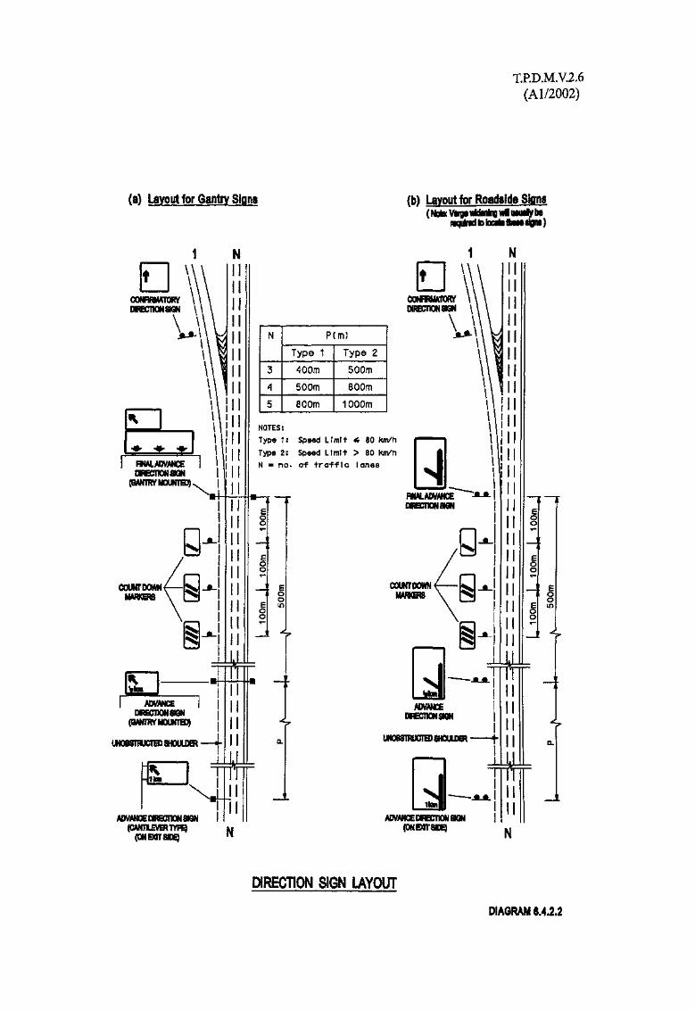
T.P.D.M.V.2.6(Al/2002)
(a) Layout for Gantry Signs (b) Layout for Roadside Signs(Note Vergs vttnftig wl uwriy be
nquMtotatoflwNilgni)
N 1V-
CONRRMATORV \ iDRBCTIONSIGN \ '
\
I RNALADVANCEDIRBHIONSON
COUNTDOWNMARKB3
I ADVANCE |DiRECnONSGN
(QANmyMOUNTH))
UNOBSTRUCTED SHOULDER
i
im
ADVANCE DIRBCTION88QN
N
3
A
5
P(m)
Type 1400m500m800m
Type 2500m800m1000m
NOTES:
Type 1: Speed LImrt ^ 80 fcm/h
Type 2: Speed Limit > 80 km/hN = no. of traffic lanes
N
DIRECTION SIGN LAYOUT
DIAGRAM 6.4.2.2

T.RD.M.V.2.6(Al/2002)
Table 6.4.2.1
Sign Locations
Sign Type
AdvanceDirection Sign
Countdown,Markers
Final AdvanceDirection Sign
ConfirmatoryDirection Sign
Cantileveror gantry orRoadside*
Roadside,)1200mm)
x )700mm)
Gantry orRoadside*
Roadside
V height(mm)
250
-
250
250250
Location
500m -1000m**before start ofdeceleration lane
300m) before) start of
200m) deceleration100m) lane
At start ofdeceleration lane
Located near gore
Illumination
Externally illuminated andreflectorised
Reflectorised
Externally illuminated andreflectorised
Reflectorised
* Mixed Cantilever/Gantry/Roadside Signs may be the best method of signing, but once aroadside sign is introduced in the sequence of approach signing, roadside signs must beused for all direction signs in advance of that roadside sign, in that particular sequence.
**The exact location depends on the higher design speed and the number of traffic lanes asshown in Diagram 6.4.2.2.
Table 6.4.2.2
Visibility Distances for Directional Signs
Sign Type
Advance Direction Sign
Final Advance Direction Sign
Confirmatory Direction Sign
Minimum clear visibilitydistance to sign (m)
180 (135 for gantry signs)
180
105
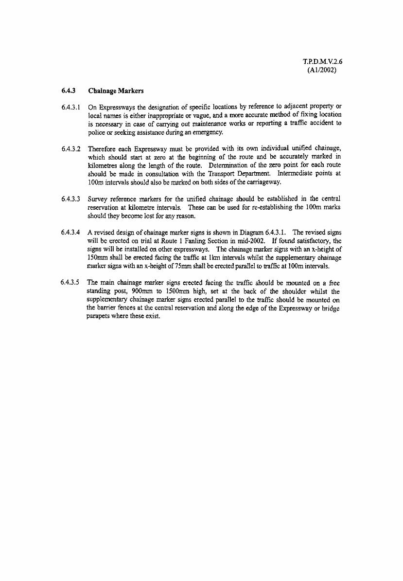
T.P.D.M.V.2.6(Al/2002)
6.43 Chainage Markers
6.4.3.1 On Expressways the designation of specific locations by reference to adjacent property orlocal names is either inappropriate or vague, and a more accurate method of fixing locationis necessary in case of carrying out maintenance works or reporting a traffic accident topolice or seeking assistance during an emergency.
6.4.3.2 Therefore each Expressway must be provided with its own individual unified chainage,which should start at zero at the beginning of the route and be accurately marked inkilometres along the length of the route. Determination of the zero point for each routeshould be made in consultation with the Transport Department. Intermediate points at100m intervals should also be marked on both sides of the carriageway.
6.4.3.3 Survey reference markers for the unified chainage should be established in the centralreservation at kilometre intervals. These can be used for re-establishing the 100m marksshould they become lost for any reason.
6.4.3.4 A revised design of chainage marker signs is shown in Diagram 6.4.3.1. The revised signswill be erected on trial at Route 1 Fanling Section in mid-2002. If found satisfactory, thesigns will be installed on other expressways. The chainage marker signs with an x~height of150mm shall be erected facing the traffic at 1km intervals whilst the supplementary chainagemarker signs with an x-height of 75mm shall be erected parallel to traffic at 100m intervals.
6.4.3.5 The main chainage marker signs erected facing the traffic should be mounted on a freestanding post, 900mm to 1500mm high, set at the back of the shoulder whilst thesupplementary chainage marker signs erected parallel to the traffic should be mounted onthe barrier fences at the central reservation and along the edge of the Expressway or bridgeparapets where these exist.
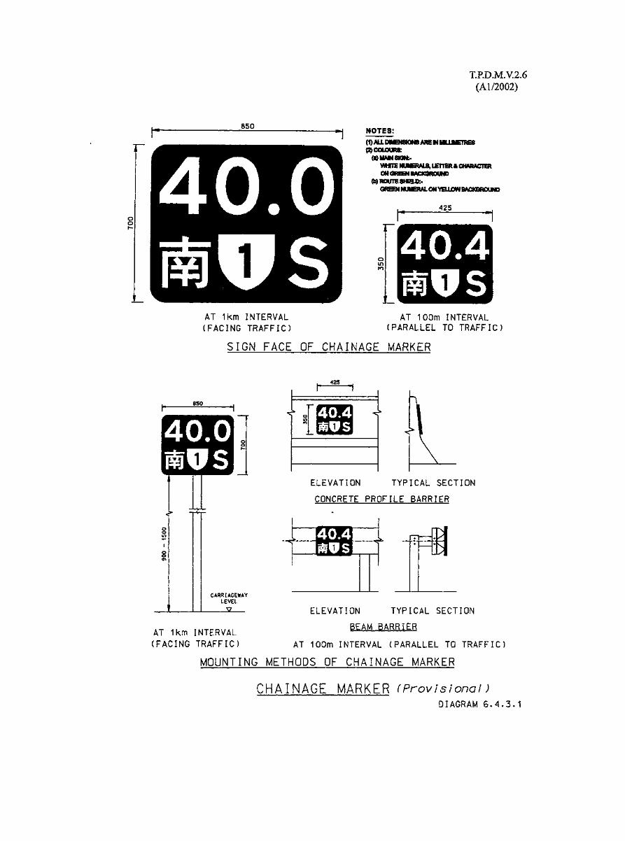

T.RD.M.V.2.6(Al/2002)
6.4.4 Road Markings and Road Studs
6.4.4.1 Reflective hot applied thermoplastic material or its equivalent, in accordance with thecurrent Highways Department Specification, but not road paint, must be used for permanentroad markings on Expressways. For temporary road markings, only preformed pavementtapes shall be used.
6.4.4.2 Detailed requirements for road markings are given in Volume 3, Chapter 5 of this manual,but for all Expressways, markings utilised must be based on the assumption of a 70 km/h ormore vehicle speed.
6.4.4.3 The removal of thermoplastic road marking material from friction course surfacing isvirtually impossible using conventional scouring methods, and it will usually be necessaryfor the whole friction course layer to be removed. Consequently, where road markingshave to be altered or removed, consideration should be given to phasing the operation tocoincide with the renewal of the friction course surfacing. If this cannot be achieved thenareas of the friction course surfacing must be removed and relaid to effectively remove theold markings. Removal of the old friction course in small patches is not acceptable, andresurfacing of a whole lane width is required, except at the edge of the carriageway where itwould be acceptable to remove the edgeline by removal and replacement of the frictioncourse over the width of the hard shoulder or marginal strip, as the case may be.
6.4.4.4 Because of the difficulty of removing thermoplastic material from the friction course,careful attention must be paid in the initial design as to the road markings proposed, in orderto avoid as far as possible, the need to have to remove them at a later date.
6.4.4.5 All lane and edge line thermoplastic road markings used on Expressways must besupplemented by road studs with reflective lenses. The studs shall not present any sharpedges to traffic. The reflective portions of the studs shall be free from crevices or ledgeswhere dirt might accumulate. The body which does not form part of the lens of the studsshall be white, silver or light grey in colour.
6.4.4.6 Reflective road studs may be of depressible or non-depressible type as described below:
(i) Non-depressible road stud
A road stud shall be either in the shape of circle having a diameter of not more than210 mm; or rectangle having a length of not more than 210 mm and a width of notmore than 170 mm which shall project not more than 6 mm at their edges nor morethan 18mm above the road surface, having a unidirectional reflective panel. Thereflective panel will usually be coloured either red, amber or green, as they should notnormally be used for lane markings.
(ii) Depressible road stud (Cats eves)
A self wiping depressible road stud shall revert to its original form after beingtraversed by a vehicle. It is approximately 180mm by 140mm and projects not morethan 25mm above the road surface. The base of the marker should be made of metaland be strong enough to withstand vehicle loading. A removable housing, usuallymade of rubber, fitted into the metal base must be able to hold at least two reflective'eyes' to face oncoming traffic which will normally be uni-directional.

TJP.D.M.V.2.6(Al/2002)
6.4.4.7 In Expressways, it is desirable to use depressible road studs as far as possible as lanemarkers.
6.4.4.8 The provision of road studs shall be in accordance with the following:
Lane lineWarning lane lineLeft hand edge (only where a hard strip orshoulder is provided)Right hand edge adjacent to central reserve(only where a hard strip is provided)Across slip road entrance/exit and lay-byTemporary road works
Colour oflens/lenses
WhiteWhiteRed
Amber
GreenYellow
Colour of bodyof studsWhiteWhiteWhite
White
WhiteFluorescent
saturn yellow
Spacing
12 or 18m6 or 9m
18m
18m
4mVaries
6.4.4.9 In most situations along Expressways only uni-directional road studs will be necessary.However, if tidal flow operations or similar are envisaged at any location, the road studsmust be bi-directional and the reflective lenses of the appropriate colours as viewed byapproaching drivers from both directions.
6.4.4.10 The specification for and installation of road studs should be in accordance with the currentHighways Department Specification.
6.4.4.11 Road studs and cats eyes must be located as shown in Diagrams 6.2.3.1 to 6.2.3.10.
6.4.4.12 Further information on permanent road studs and their use may be found in Chapter 5 ofVolume 3.
6.4.4.13 At road works along an Expressway it is sometimes necessary or advisable to use temporaryroad studs, to delineate traffic lanes, which are yellow bodied studs with appropriatelycoloured lenses. Only temporary reflective road studs approved by CHE/R&D shall beused for temporary road works. They shall be designed to be removed without damage tothe road surface. Such studs must however conform to the Highways DepartmentSpecification.

T.PD.M.V.2.6(Al/2002)
6.5 Lane and Carriageway Closures
6.5,1 General Requirements
6.5.1.1 All temporary signing, guarding and lighting for lane or carriageway closures in respect of:
(i) road works;
(ii) road and horticultural maintenance;
(iii) road cleansing;
(iv) traffic control after traffic accidents;
(v) traffic control in emergency situations; and
(vi) any other temporary traffic diversion arrangement;
must be carried out in accordance with the Code of Practice for the Lighting, Signing andGuarding of Road Works.
6.5.1.2 Guidance for the closure of a lane or lanes of a dual carriageway by means of temporaryroad signs is given in Fig. 8.1 to 8.5 of the Code of Practice.
6.5.1.3 A single lane closure (slow lane) will require similar advance signing to that in Fig. 8.1 to8.4 of the Code of Practice except that the "advanced warning of closure of traffic lane" signTS 497 would be changed to TS 494. Additionally only the first half of the taper would berequired and the line of cones in the parallel section would of course be moved to the edgeof the slow lane.
6.5.1.4 In respect of a closure of hard shoulder Fig. 8.5 of the Code of Practice illustrates thesigning required.
6.5.1.5 The Traffic Console of the Regional Traffic Police Command Centre must always beinformed before a lane closure is implemented.
6.5.1.6 Wherever possible and particularly for major works, the Regional Traffic Police should beconsulted at least 28 days prior to commencement of the works.

T.P.D.MV.2.6(Al/2002)
6.6 Maintenance Operations Centres (MOC)
6.6.1 Location and Use
6.6.1.1 The patrol, emergency attendance, cleansing and maintenance of the Expressway should beadministered from a Maintenance Operations Centre (MOC), conveniently located at or neara grade separated junction on the length of Expressway concerned.
6.6.1.2 The length of Expressway that may be administered from one MOC, will depend on thegeographical layout and the complexity of the roads in question, but about 40 km may betaken as a guide. Providing the MOC is centrally located the response time for an incidenton any part of the Expressway should be under 30 minutes.
6.6.1.3 Location at or near a grade separated junction is very important and for reasons of efficiencyand economy, it is essential that the junction chosen has four way access to and from theExpressway. Provision of grade separated facilities on the Expressway, specifically for theMOC, may be acceptable but are unlikely to be economically justified.

T.RD.M.V.2.6(Al/2002)
6.7 Service Areas
6.7.1 Location
6.7.1.1 In planning the Expressway system, sites suitable for service areas should be sited atapproximately 30 km intervals in respect of both directions of travel.
6.7.1.2 Ideally service areas should be provided opposite each other on both sides of theExpressway, with, where possible, an overbridge across the Expressway to allow theconnection of rear access roads for use by vehicles servicing the Service Areas, but not thegeneral public, other than perhaps as pedestrians.
6.7.1.3 Each service area will require about 3 hectares of land depending on the type of facilities tobe provided.
6.7.1.4 Each service area will require as shown in Diagram 6.7.1.1, its own separate slip roadconnections to and from the Expressway which must be designed to the full standard inaccordance with Section 6.3 of this Chapter, complete with acceleration and decelerationlanes.
6.7.1.5 Where it is not possible to provide service areas in pairs opposite each other considerationshould be given to having a single 4 hectare site located adjacent to a grade separatedjunction. However access to the service area must be able to be provided from aconvenient side road or directly from a roundabout, as direct access to a service area fromthe junction's slip roads is unacceptable.
6.7.1.6 In selecting sites, consideration should be given to the availability of sewerage, water, gas,electricity and telephone services and to the proximity of local transport which staff mayneed.

T.P.D.M.V.2.6(A1/2002)
IDEALLY, LEVEL OF SITE-SHOULD BE ABOVE THATOF THE EXPRESSWAY.
BEARS? MINOR ROAD€ ROSSI t^8 OVER EXPRESSWAYALLOWS CONNECTION OFACCESS gOAPS FORSERVICE VEHICLES.
CONTROLtED ACCESS RDAQSW(TH LOCKASlg 6ATES.ftOT FOi USE BY THE
PUBLIC;.
PARKiMG PACIiiTICS 6H EACH SlOE OF EKI^ESSWAYCARS AND UfiHT VEHICLES^ l i dHEAVY GOODS VEHICLES - Sf
DETAILED LAYOUT OF SERVICE ARIAWILL VARY ACCORDS TO THETOPOGRAPHY, LOCATION , ACCESS ate.THIS i$ MERELY AH iXAHPLE OFWHAT A SERVICE AREA HISHTLOOK UKg.
EXPRESSWAY SERVICE AREA
NOT TO SCALE
DIAGRAM 6.7.1.1

T.P.D.M.V.2.6(Al/2002)
6.7.2 Facilities
6.7.2.1 The facilities provide at each service area may include:
(i) parking for cars and heavy goods vehicles;
(ii) toilets;
(iii) fast food facility;
(iv) petrol filling station; and
(v) vehicle recovery service.
6,2.2 The petrol filling station, which is essential to all service areas, should be the last facilitybefore traffic rejoins the Expressway.
6.7.2.3 Where rear access is provided, see paragraph 6.7.1.2, the access should be for the use ofstaff vehicles, supply vehicles, emergency service vehicles, breakdown lorries andexpressway maintenance vehicles only, and to ensure this the access roads should be closedby means of lockable gates. The general public must not be permitted to use these serviceroads for vehicular access. However where identical facilities cannot be provided for eachopposite service, consideration might be given to using the service road as a pedestrian link.
6.7.2.4 Part of the site should be set aside for landscape works to help screen the service area.
6.7.2.5 Service Areas should be signed at regular intervals, in advance, to allow drivers to makerational decisions on where they wish to stop. The signface designs for Service Areadirectional signs are illustrated in Diagram 6.7.2.1, but Chapter 3 of Volume 3 should alsobe referred to.
6.7.2.6 On joining an Expressway where service areas are provided, drivers should be informed ofthe distance in 'km' to the next service area by appropriate signing as indicated in (i) inDiagram 6.7.2.1. The sign should be placed about 200m beyond the end of the accelerationtaper i.e. about 100 m beyond the Expressway confirmation sign, see paragraph 6.4.1.5.The sign should be located at the rear of the hard shoulder or hardened verge.
6.7.2.7 Where junctions are closely spaced it is sufficient to have the distance informatory sign, in (i)in Diagram 6.7.2.1, erected only at the far junction of a pair of closely spaced junctions.As a guide in this respect the signs need not be closer to each other than 5 km.
6.7.2.8 Where a service road has its own direct access slip roads serving it from the Expressway,signing should be in accordance with the normal junction signing as set down in Chapter 3of Volume 3, that is, there should be an Advance Direction Sign, 1/2 km in advance of theservice area, a Final Advance Direction Sign at the start of the slip road and a Direction Signat the nose of the junction. However as explained in Chapter 3, Volume 3, Section 3.5.7,directional signs should only show the direction to the service area and not forwarddestinations beyond this. Also in terms of the symbols to be used it is not really necessaryto include the parking symbol 'Pf if the refreshment symbol is used, as it can be assumed thatparking will be provided.


T.P.D.M.V.2.6(Al/2002)
6.7.2.9 Where a service area is located on a minor road served by a grade separated junction fromthe Expressway the appropriate symbols for the service area should be incorporated into thedirectional signs for the junction.

T.P.D.M. V.2.6(Al/2002)
6.8 Operation and Management
6.8.1 Utility Services
6.8.1.1 Expressways should not be used for the location of utility services which are not related tothe operation of the Expressway, except of course for services which are essential to theoperation of the Expressway such as power cables for the road lighting, and telephone linesfor the emergency telephones as well as power and communication cables for trafficsurveillance and control facilities.
6.8.1.2 In the event that a non-operational utility service is required to be placed along or across anExpressway consent in writing with justification to allow this must be obtained from theRegional Chief Highway Engineer of Highways Department. Approval should not begiven unless:
(i) it is in the interest of the public for the proposed services to be installed;
(ii) the installation works would not involve any open cut excavation works within thecarriageway or the hard shoulder nor would require any access from the Expressway;
(iii) the underground services are installed in such a way that it will not be necessary toexcavate any part of the carriageway and hard shoulder for future inspection,maintenance or replacement.
6.8.1.3 Additionally such utility services should only be permitted to be laid along adjacent verge.In the situation that non-operational utility services need to be laid across an Expresswaybeneath the carriageway, their provision should be such that for any future inspection,maintenance or replacement it will not be necessary to excavate any part of the carriagewayand preferably any part of the hard shoulder, nor should manholes for these service bepermitted in the carriageway and, if possible, not in the hard shoulder either.
6.8.1.4 Where there are existing non-operational services in an Expressway, consideration should begiven to their removal or relocation when repairs or alterations are being entertained.
6.8.1.5 Any illegal services encountered within the boundary of the Expressway should be removedas quickly as possible. Such illegal services will generally be a safety hazard and veryoften produce highway maintenance problems due to their presence.
T.P.D.M. V.2.6(Al/2002)
6,8.2 Activities Affecting Operation
6.8.2.1 Advertisements
It is not appropriate for any advertising or decoration materials to be displayed on oradjacent to an Expressway. In this respect an advertisement must include any sign ordevice extraneous to the operation of an Expressway, such as:
(i) decorative lights at Christmas and Chinese New Year or at any other time;
(ii) business advertisements, including election posters;
(iii) bunting, flags and drapes for special visits;
(iv) notice boards and display cubes indicating particular Districts; and
(v) flower/planting displays, additional to any agreed landscaping requirements.
Advertisements at locations such as junctions, approaches to low bridges or other placeswhere special traffic hazards may exist should be discouraged.
6.8.2.2 Contra-flow Working
From time to time it may be necessary to introduce contra flow working along anExpressway in order to carry out certain maintenance works. It is not appropriate to try toforesee such events by the provision of permanent emergency crossings for this purpose, forthe following reasons:
(i) the precise location will be dictated by the location and extent of any works, whichcan only be determined at the time the works are required;
(ii) the length to be provided for the gap in the central reserve is difficult to determine inadvance as it will be related to traffic and operating conditions at the time the worksare required to be carried out, as a general guide a gap of at least 30m will generallybe required but at times this may need to be substantially increased; and
(iii) the provision of such a large gap at times of non-use, increases the accident potentialin terms of vehicles striking any ramped down section of any barrier fence andbreaking through into the opposing carriageway.

T.P.D.M. V.2.6(Al/2002)
6.8.3 Emergency Telephones
6.8.3.1 Chapter 3 of Volume 10 provides advice on the provision of Emergency Telephones andshould be referred to.
6.8.4 Traffic Control and Surveillance Equipment
6.8.4.1 A policy has yet to be determined on the use of lane control signals or surveillanceequipment for Expressways and therefore where it is considered that such equipment may beadvantageous the iTransport Division of the Transport Department should be consulted.
6.8.4.2 Further advice on surveillance methods for such roads will be provided in Volume 10.
6.8.5 Vehicle Recovery
6.8.5.1 There is at present no policy regarding the appointment by Government of an authority to beofficially responsible for the recovery of vehicles on Expressways except Tsing Ma ControlArea, and at present this is left to the individual owners of the vehicles to arrange.


![OUG - Hitachi ElevatorEN HKG COP HKG COPSS550 SS550MS EN MS EN/HKG COP/SS550/MS Load [kg] Speed [m/min] Minimum pit depth : P [mm] Maximum pit depth : P [mm] Counterweight location](https://static.documents.pub/doc/80x56/60ba10ba8d93e149dc71e79d/oug-hitachi-en-hkg-cop-hkg-copss550-ss550ms-en-ms-enhkg-copss550ms-load-kg.jpg)


