172


PART 4
Guide to Design of Seawalls and Breakwaters
BOOKS REGISTRATION ORDINANCF
2 0 0 3 - 0 9 5 4 7Chapter 142 | M
Civil Engineering OfficeCivil Engineering DepartmentThe Government of the Hong Kong Special Administrative Region
© The Government of the Hong Kong Special Administrative Region
First published, July 2003
Prepared by:
Civil Engineering Office,
Civil Engineering Department,
101 Princess Margaret Road,
Homantin, Kowloon,
Hong Kong.
Purchased orders should be placed with :
Publication Sales Section,
Information Services Department,
Room 402, 4/F, Murray Building,
Garden Road,
Hong Kong.
Price in Hong Kong ; HK$50
Price overseas : US$11.5 (including surface postage)
An additional bank charge of HK$50 or US$6.5 is required per cheque made in currenciesother than Hong Kong dollars.
Cheques, bank drafts or money orders must be made payable to
The Government of the Hong Kong Special Administrative Region

The Port Works Design Manual presents recommended standards and methodologies
for the design of marine works in Hong Kong. It consists of five separate volumes, namely,
Part 1 to Part 5. Part 1 mainly covers design considerations and requirements that are
generally applicable to various types of marine works. Part 2 to Part 5 are concerned with
specific design aspects of individual types of works including piers, dolphins, reclamations,
seawalls, breakwaters and beaches. This Manual supersedes the Port Works Manual
prepared in the 80's.
This document, Port Works Design Manual: Part 4, gives guidance and
recommendations on the design of seawalls and breakwaters. It was prepared by a working
committee comprising staff of the Civil Engineering Office and Special Duties Office with
reference to the latest local and overseas design standards and experiences in consultation
with other Government departments, engineering practitioners and professional bodies.
Many individuals and organizations made very useful comments, which have been taken into
account in drafting the document. An independent review was undertaken by experts before
the document was finalized. All contributions are gratefully acknowledged.
Practitioners are encouraged to comment at any time to the Civil Engineering Office
on the contents of this document, so that improvements can be made to future editions.
VA a—7CCChan
Head, Civil Engineering Office
May 2003

Working Committee of Port Works Manual: Part 4
The preparation of the document was overseen by Chief Engineer/Technical Services :
IT Anthony Loo
The document was drafted by the following staff of the Civil Engineering Office :
Ir Lee Wai-ping
Ir Wong Chi-pan
Ir Wong Ching-piu
Assistance and advice were provided by the following staff of the Civil Engineering Office and
Special Duties Office:
Ir Chiu Mau-fat
Ir Ko Wai-kuen
Ir Lam Chi-keung
Ir Li Yuen-wing
The document was reviewed by :
Professor Yoshimi Goda, Yokohama National University
Professor Lee Chack-fan, the University of Hong Kong
Extracts from British Standards are reproduced by permission of British Standards Institution (BSI)
under licence number 2001/SK0316. British Standards can be obtained from BSI Customer Services,
389 Chiswick High Road, London W4 4AL, United Kingdom.
Extracts from CIRIA Special Publication 83 "Manual on the use of rock in coastal and shoreline
engineering" are reproduced by permission of CIRIA. This document may be obtained from CIRIA,
6 Storey's Gate, Westminster, London SW1P 3AU.
Extracts from "R&D Technical Report W178 - Overtopping of Seawalls : Design and Assessment
Manual" are reproduced by permission of Environment Agency, 2440 The Quadrant, Aztec West,
Almondsbury, Bristol, BS32 4AQ.
Extracts from "Random Seas and Design of Maritime Structures" published by World Scientific are
reproduced by permission of Professor Yoshimi Goda.

CONTENTS
PageNo.
TITLE PAGE 1
FOREWORD 3
CONTENTS 5
1. INTRODUCTION 9
1.1 Purpose 91.2 Definitions and References 10
2. TYPES OF STRUCTURES 11
2.1 General 112.2 Breakwaters 11
2.2.1 Functions 112.2.2 Rubble Mound Breakwaters 112.2.3 Vertical Breakwaters 122.2.4 Composite Breakwaters 122.2.5 Selection 12
2.3 Seawalls 132.3.1 Functions 132.3.2 Concrete Blockwork Seawalls 132.3.3 Caisson Seawalls 142.3.4 Wave Absorption Vertical Seawalls 142.3.5 Rubble Mound Sloping Seawalls 142.3.6 Selection 15
3. LAYOUT CONSIDERATIONS 17
3.1 General 173.2 Breakwaters 17
3.2.1 General 173.2.2 Wave Penetration 173.2.3 Port Operation and Navigation 183.2.4 Environmental Effect 19
3.3 Seawalls 20

PageNo.
4. FOUNDATIONS 21
4.1 General 21
4.2 Site Investigation 214.3 Stability 21
4.3.1 Factor of Safety against Soil Shear Failure 214.3.2 Soil Conditions 22
4.3.3 Loading 234.4 Settlement 234.5 Types of Foundation 24
4.5.1 Dredging 244.5.2 Deep Cement Mixing 244.5.3 Stone Columns 264.5.4 Comparison of Foundation Types 27
4.6 Design Approach 274.6.1 Dredging 274.6.2 Deep Cement Mixing 284.6.3 Stone Columns 28
5. HYDRAULIC PERFORMANCE 31
5.1 General 315.2 Wave Run-up 315.3 Wave Overtopping 31
5.3.1 Mean Overtopping Rate 315.3.2 Permissible Overtopping Rate 32
5.4 Wave Reflection 335.4.1 Reflected Wave Height 335.4.2 Wave Reflection in the Harbour 345.4.3 Wave Absorption Structures 34
5.5 Wave Transmission 34
6. STRUCTURAL STABILITY 37
6.1 General 376.2 Rubble Mound Structures 37
6.2.1 General 376.2.2 Weight of Armour Units 376.2.3 Thickness and Extent of Armour Layer 396.2.4 Underlayers and Core 40

PageNo.
6.2.5 Slope of Structure 426.2.6 Crest 426.2.7 Crest Structures 426.2.8 Toe Protection 436.2.9 Breakwater Head 43
6.3 Vertical Structures 446.3.1 General 446.3.2 Overturning, Sliding and Bearing Capacity 456.3.3 Design Wave Height 466.3.4 Impulsive Wave Pressure 476.3.5 Toe Protection 476.3.6 Breakwater Head 47
6.4 Vertical Wave Absorption Seawalls 48
7. CONSTRUCTION 49
7.1 General 497.2 Foundation Dredging 49
7.2.1 General 497.2.2 Samples of Dredged Materials 497.2.3 Dredging Profile and Depth 497.2.4 Disposal of Dredged Materials 50
7.3 Soil Strengthening 517.4 Fill Placement 517.5 Rock Armour and Underlayers 527.6 Concrete Armour 537.7 Bermstones 547.8 Concrete Seawall Blocks 557.9 Facing Stones and Copings 557.10 Caissons 567.11 Joints for Seawall Caissons 56
8. MARINE AND MAINTENANCE FACILITIES 59
8.1 General 598.2 Marine Facilities 598.3 Maintenance Facilities 60

PageNo.
9. MISCELLANEOUS STRUCTURES 63
9.1 General 63
9.2 Pumphouses 639.2.1 General 63
9.2.2 Layout and Location 639.2.3 Structure and Design 639.2.4 Ties and Waterstops 649.2.5 Screens, Guides and Fittings 65
9.3 Slipways and Ramps 659.3.1 Location and Basic Dimensions 659.3.2 Slipway Design 669.3.3 Ramp Design 67
9.4 Outfalls and Intakes 679.5 Beacons 68
REFERENCES 69
TABLES 73List of Tables 75Tables 77
FIGURES 83List of Figures 85Figures 87
APPENDIX A MARINE GROUND INVESTIGATION IN DIFFICULT 107GROUND AREAS
APPENDIX B ASSESSMENT OF HYDRAULIC PERFORMANCE 113
APPENDIX C DETERMINATION OF SIZE OF ARMOUR 133
APPENDIX D WORKED EXAMPLES 145
GLOSSARY OF TERMS AND SYMBOLS 161
1.
1.1 Purpose
The purpose of the Port Works Design Manual (the Manual) is to offer guidance on the
design of marine works and structures normally constructed by the Government of the Hong
Kong Special Administrative Region. Such works and structures include public piers, ferry
piers, dolphins, reclamations, seawalls, breakwaters, pumphouses, beaches and associated
marine facilities. The Manual has been written with reference to the local conditions and
experience. Therefore, it may also provide a source of useful data and design reference for
other marine works and structures constructed by other organizations or parties in HongKong.
The Manual is issued in five separate parts. The titles of these parts are :
• Part 1 - General Design Considerations for Marine Works
® Part 2 - Guide to Design of Piers and Dolphins
• Part 3 - Guide to Design of Reclamation
® Part 4 - Guide to Design of Seawalls and Breakwaters
® Part 5 - Guide to Design of Beaches
The recommendations given in the Manual are for guidance only and should not be taken as
mandatory. Compliance with these recommendations does not confer immunity from
relevant statutory and legal requirements. Because of the variable nature of the marine
environment, the design of marine works and structures relies particularly on the use of sound
engineering judgement and experience. Practitioners should be aware of the limitations of
the assumptions employed in a particular theoretical or computational method. Since the
marine environment is a field where active research and development are continuing, it is
beyond the scope of the Manual to cover all analysis and design methods. Practitioners
should be prepared to explore other methods to suit a particular problem and should also
realize that many of the methods will continue to evolve.
This part (Part 4) of the Manual gives guidance and recommendations on the design of
seawalls and breakwaters, covering aspects on the choice of types and layouts of structures,
foundation, hydraulic performance, structural stability, construction and maintenance. It
also includes design of minor marine structures and facilities normally associated with the
construction of seawalls and breakwaters. Worked examples are provided in Appendix D to
illustrate the application of the design methods. In using this part of the Manual, readers

10
should refer to other parts of the Manual on particular aspects, as necessary.
1.2 References
The definitions of terms and meanings of symbols for the purpose of this part of the Manual
are given in the Glossary of Terms and Glossary of Symbols at the end of this document.
Meaning of symbols not shown in the glossary is given in each case in the text.
The titles of the publications referred to In this part of the Manual are listed in the reference
section. Readers should consult these original publications for more detailed coverage of
particular aspects. For Works Bureau Technical Circulars (WBTC) or Environmental,
Transport and Works Bureau Technical Circular (Works) which are updated regularly,
reference should be made to their latest issues.

11
2. OF
2.1 General
This chapter discusses the characteristics of various types of breakwaters and seawalls, and
provides general guidance on the selection of an appropriate structural form for thesestructures.
2.2 Breakwaters
2.2.1 Functions
A breakwater is a structure employed to reflect and dissipate the energy of water waves and
thus prevent or reduce wave action in a water area it is desired to protect. Breakwaters may
be constructed to form a harbour or typhoon shelter and create sufficiently calm water,
thereby providing protection for safe navigation, berthing and mooring of vessels, and other
harbour activities. Breakwaters may sometimes serve as aids to navigation or shore
protection or as both. There are three main types of breakwaters, namely, rubble mound
breakwater, vertical breakwater and composite breakwater.
2.2.2 Rubble Mound Breakwaters
Rubble mound breakwater is a commonly used type of breakwater structure in Hong Kong
(see Figure 1). It is typically constructed with a core of quarry-run stone that is protected
from wave action by one or more rock underlayers and an outer layer composed of massive
rocks or specially shaped concrete armour units (Figure 2). A concrete crest structure may
be constructed on the mound to provide access or, with the incorporation of a wave wall, to
prevent or reduce wave overtopping.
Figure 1 indicates the components of a typical rubble mound breakwater. Their functions
are summarized as follows:
• Foundation - Provides embankment stability.
• Scour protection apron - Prevents erosion.• Core - Provides bulk of structure and reduces wave transmission.
• Toe mound - Supports the main armour and prevents toe scouring.
• Underlayer - Acts as filter between core and armour layer and bedding for
12
placement of armour.« Rear face armour - Protects core from overtopping waves and against wave
action inside the harbour.
• Main armour - Provides wave protection.
• Concrete crest structure - Provides access and reduces wave overtopping.
The properties of armour rock should comply with the requirements given in Section 21 of
the General Specification for Civil Engineering Works (GS) (Hong Kong Government, 1992).
For armour design, it is recommended that the specific gravity of the rock, if obtained locally,
should be taken as 2.6. This figure corresponds to the minimum requirement of specific
gravity given in Section 21 of the GS. A value higher than 2.6 should not be used for design
without extensive testing, both prior to construction, where a rock source has been identified,
and during construction for quality control.
2.2.3 Vertical Breakwaters
A vertical breakwater is one in which wave attack is resisted primarily by a vertically faced
structure extending directly from seabed level. Structures comprising reinforced concrete
caissons are common forms of vertical breakwaters. They are usually designed for floating
into position from a dry dock or a floating dock and sinking to the seabed foundation.
Typical sections of caisson type vertical breakwaters are shown in Figure 1.
2.2.4 Composite Breakwaters
A composite breakwater is a combined structure consisting of a vertical structure placed on a
rubble mound that is submerged at all tidal levels. Typical cross section of a composite
breakwater with reinforced concrete caisson is shown in Figure 1. This type of structure
may be used as a breakwater in very deep water where the volume of rock required for a
rubble mound structure is not available or when it is not practicable to design a vertical face
structure to carry the design wave loading to the full depth.
2.2.5 Selection
The following factors should be considered when selecting the type of structures:
• Layout of breakwaters.
® Environmental conditions.

13
• Operational conditions.
• Navigation requirements.
• Construction conditions and periods.
• Construction cost.
• Availability of construction material
« Maintenance.
In general, it is necessary to compare the merits and costs of different types of structure under
the respective site conditions and project constraints before a decision Is made. A general
comparison of the applications of the three types of breakwater is shown In Table 1.
23 Seawalls
2.3.1 Functions
A seawall can be used as a soil retaining structure of a reclamation or as an armouring
structure to protect a shoreline from erosion against wave and current actions. Seawalls
may be vertical or sloping. Vertical seawalls have the advantage that they can provide
marine frontage for vessel berthing and cargo handling. If necessary, wave absorption units
can be included on vertical seawalls to reduce wave agitation inside a harbour.
23.2 Concrete Blockwork Seawalls
Concrete blockwork seawalls are gravity structures made up of precast concrete blocks.
Typical layout of a concrete blockwork seawall is shown in Figure 3.
Concrete blockwork structures are commonly used in Hong Kong. They have the following
advantages:
® Relatively low cost of construction.
• Long history of satisfactory performance with negligible need for maintenance.
• Flexibility to cope with some differential foundation settlement.
• Damage from vessels in accidents is usually minor.
• Incorporation of landings, pumphouses and drainage outfalls is relatively
simple.
Disadvantages of concrete blockwork structures relate mainly to the relatively long

14
construction period required, and the need for a large casting yard and stacking area with
marine frontage. These disadvantages, however, can generally be reduced in significance
with adequate project planning, as many such blocks can now be cast in the Mainland and
delivered to site when required. Another disadvantage is that vertical walls reflect waves,
with the consequence that wave activity in an adjacent area is increased.
2.3.3
Apart from precast concrete blocks, the earth retaining function of a seawall can be provided
by means of concrete caissons as shown in Figure 3. The caissons are usually cast in a dry
dock or on a floating dock and transported to the site by floatation before sinking into the
designated locations. Because of the relatively high mobilization cost for a caisson seawall,
it is usually not economical to use caissons for a short seawall or in limited water depth.
2.3.4 Wave Vertical
Vertical seawalls with solid face are highly reflective of wave energy. This may not be
acceptable inside a harbour as wave agitation will affect vessel operation and navigation.
Wave reflection can be reduced by introducing wave absorption units on the vertical seawalls.
A wide variety of wave absorption vertical seawall have been developed over the years under
different wave conditions and application constraints in different places. An example of a
wave absorption seawall is shown in Figure 3. It contains a wave absorption chamber with
perforated front wall that allows flow into and out of the chamber. The degree of wave
absorption capacity depends very much on the size of the wave absorption chamber relative
to the incoming wavelength. Normally, wave reflection is minimized when the width of the
chamber is 10% to 20% of the incoming wavelength, provided the perforation ratio, defined
as the ratio between the area of the perforations and the total area of the front wall, is around
30%. The suitability of the application of the seawall at a particular site should be subject tomodel tests.
2.3.5 Rubble Mound Sloping Seawalls
A typical cross-section of a rubble mound sloping seawall is shown in Figure 4. The slope
of the seawall is generally protected by rock armour. If the wave condition renders the rock
size not economically available in the market, concrete armour units can be used as analternative to protect the slope of the seawall.

15
The advantage of a rubble mound sloping seawall are :
• Construction generally simpler and faster than a vertical seawall.
• More tolerable to differential settlement.
• Reduced reflected wave height due to dissipation of wave energy on the slope
of the structure.
• Less wave overtopping than a vertical wall with a solid face.
• Easier to carry out maintenance.
A sloping seawall may not be a suitable form of construction if marine frontage for vessel
berthing or cargo handling is required. However, a piled deck structure can be constructed
over the rubble mound to form a berth for vessels. Another drawback is that a wider
clearance has to be provided for marine traffic due to the underwater slopes, which may
sometimes be not practicable when water space is limited.
2.3.6 Selection
Factors to be considered in selecting the type of seawall are similar to those for breakwaters
listed in Section 2.2.5, with due consideration of the relative merits and demerits oi
individual types of seawalls discussed in Sections 2.3.2 to 2.3.5. If reinforced concrete is
used, reference should be made to Chapter 6 of Part 1 of the Manual on the concrete
specification and corrosion protection measures.

16
17
3.
3.1 General
This chapter provides general guidelines on designing the layout of breakwaters and seawalls,
in particular on the setting and alignment of these structures.
3.2 Breakwaters
3.2.1 General
The layout of breakwaters for typhoon shelter or harbour basin should be determined by
considering the following factors :
• Required sheltered conditions for vessels at berth or anchorage.
® Maneuvering areas for vessels within the sheltered area.
• Adequate stopping distance for vessels entering the entrance at a safe
navigating speed.
Analysis should be carried out when determining the layout of breakwaters to evaluate the
extent of wave penetration, the requirements of port operation and navigation, and the
environmental impact. Since the size of the sheltered area is determined by
manoeuverability, vessel characteristics, berthing and mooring requirements, Marine
Department and users should be consulted in designing the layout.
3.2.2 Wave Penetration
Wave diffraction through the entrance of breakwaters will affect the degree of shelter
provided and spread of waves into the basin. Hence, it is first necessary to establish the
wave conditions just outside the entrance, then to determine the effect of the entrance in
permitting waves to enter the sheltered area, and finally to determine the responses at critical
positions. Wave direction is important and, whilst the greatest shelter should be provided
against the largest waves, less critical wave conditions from other directions should also be
considered in the layout. Some important points that should be noted are summarized
below:
® The layout of the heads of the main and lee breakwaters should preferably be

18
designed to give an overlap to prevent direct penetration of the most severe
waves into the protected area (See Figure 5).« The overlap of the main and lee breakwaters against the direction of wave
propagation should ensure that no direct penetration of the Incident waves will
reach the anchorage areas for small vessels.
« Wave transmission through the structure can occur with a very porous rubble
mound, for example, one constructed only of large rocks, where the degree of
transmission increases appreciably with wave period. Therefore, this type of
structure should be avoided for breakwaters of harbour basin or typhoon
shelter.• The effect of waves generated from vessels in adjacent fairways should be
considered In locating the entrance of a harbour for small vessels. Normally,
ship waves do not Interfere the navigation and anchorage of ocean-going
vessels.« The entrance location should avoid penetration of swells or long period waves
that may Induce possible resonance motion on vessels Inside the basin.
« Where wave overtopping Is a problem, a wave wall may be constructed on the
structure to reduce the overtopping quantity. For vertical and composite
breakwaters, the wave wall can be constructed of concrete as an Integral part of
the breakwaters. There is no joint between the wave wall and the concrete of
the caissons. The wave wall is not subject to uplift, and the horizontal wave
force acting on the wave wall Is added to the wave force acting on the caisson
part for the examination of the stability of the upright sections.
A preliminary estimate of the degree of diffraction In a sheltered area may be estimated using
the diagrams in Figures 6 and 7. A fairly flat seabed is assumed in these figures. For more
realistic estimate of the wave conditions, mathematical wave modelling may be applied.
Guidance on mathematical wave modelling is given in Chapter 2 of Part 1 of the Manual -
General Design Consideration for Marine Works.
3.2.3 Port Operation and Navigation
Currents can be generated across an entrance of the harbour basin or typhoon shelter as a
result of the deflection of currents around the head of the breakwater. A wide entrance may
ease navigation but this will be in conflict with the objective of limiting wave penetration.
Some compromise may be necessary, and the advice of Marine Department and experienced
mariners Is essential in determining the optimum layout of breakwaters at the entrance, takinginto account any limits on navigation and port operation.

19
Reflection from the seaward face of a solid face vertical breakwater can set up standing wave
patterns which can result in increase wave agitation and affect navigation in front of the
breakwater. This effect may be reduced if the alignment is convex outward in the seaward
side instead of a straight one. A concave alignment, which will create severe wave
concentration on the seaward side of the structure, should be avoided. Wave absorption
chamber may be constructed on vertical breakwaters to reduce wave reflection. A wave
study on the change in wave climate due to new breakwaters should be earned out to
ascertain the effect on port operation and navigation.
3.2.4
A breakwater may cause change in the hydrodynamic regime. Hence, it is necessary to
undertake hydraulic study and environmental impact assessment to ensure that the changes in
flow and wave climate during and after construction will have no unacceptable effects on :
• Tidal flushing and water quality.
• Ecology.
• Siltation and seabed scouring.
« Sediment transport and shoreline stability of existing beaches.
An example of the impact on sediment transport is illustrated in Figure 5, showing the
possibility of up-drift sediment accretion and down-drift erosion of the shoreline after the
construction of breakwaters. Up-drift accretion can eventually cause the formation of a bar
across the entrance of breakwaters which will then require frequent maintenance dredging.
Down-drift erosion can lead to loss of beaches and the need for coastal protection measures,
which can extend a long way from the harbour. Such impact should be carefully assessed
when longshore sediment transport is a major feature of the shoreline. Examples of how
beaches will behave after construction of breakwaters on a sandy coast are given in OCDI
(2000).
The construction of breakwaters will result in an area of water relatively undisturbed by
waves and currents. As far as is practicable no major drainage sources should be allowed to
discharge into the harbour basin or typhoon shelter, resulting in pollution and settlement of
sediment in the sheltered water. Openings or culverts may be provided at suitable positions
along the breakwaters to increase flow circulation. The effect of wave penetration should be
assessed when determining the positions of these openings.

20
3.3
Seawalls are usually edge structures of reclamation. The determination of their layout with
respect to alignment, crest level, operation, navigation and environment are related to the
reclamation design, and is covered in Part 3 of the Manual - Guide to Design of Reclamation.
Specific aspects are listed as follows :
• Wave reflection from solid face vertical seawalls can lead to wave agitation in
the harbour, affecting port operation and navigation. Vertical seawalls with
wave absorption units or nibble mound sloping seawalls should be considered
to reduce the effect of reflection at a particular site.
• Vertical seawalls are generally required where marine frontage is required for
vessel berthing and cargo handling, or where water space is not sufficient to
accommodate the underwater slope of nibble mound seawalls.
® Seawalls built to protect land from wave actions may be provided with wave
walls to minimize the amount of wave overtopping. A wave wall or a parapet
wall can be constructed as an integral part of a seawall. It also serves to
prevent people promenading at the waterfront from falling into the sea.
2!
4.
4.1 General
The structure and its foundation should be designed so that, during the design life, foundation
displacements and movements are kept within the limits that the structure can tolerate
without affecting its structural integrity and functional capability. This chapter gives general
guidance on the design of foundations for seawalls and breakwaters. The information given
in BS 8004 (BSI, 1986), although mainly related to the foundations of buildings and general
engineering structures, may also provide useful reference for marine structures. One
important aspect in the design of foundation is the stability of the seabed and the possibility
of scour and undermining around the structure under wave and current actions. This iscovered in Chapter 6 of this part of the Manual
4.2 Site Investigation
Reference should be made to Geoguide 2 (GCO, 1987) for guidance on good site
investigation practice, Geoguide 3 (GCO, 1988) for guidance on description of rocks and
soils in Hong Kong, and Geospec 3 (GEO, 2001) for model specification for soil testing.
Specific details of site investigation and soil testing for marine works are given in Chapter 4
of Part 1 of the Manual.
Difficult ground conditions generally refer to the existence of unfavourable subsoil strata on
site. The presence of such conditions, if not properly handled, may lead to both problems at
the construction stage and during the future use of seawalls, breakwaters and reclamation.
Guidelines for site investigation in such conditions are given in the report "Study on Coastal
Subsoil Geotechnical Conditions" (CED, 2003). A summary of the guidelines, including
the spacing of the points of exploration, depth of penetration and vertical intervals of in-situ
tests and soil sampling, is shown in Appendix A.
4.3 Stability
4.3.1 Factor of Safety against Soil Shear Failure
The global factor of safety should be used when designing the foundation of marine works
against slip failure. It may be taken as the ratio of average available shear strength of the

22
soil along the critical slip surface to that required for maintaining equilibrium. Where soil
properties have been tested, the following minimum factors of safety are recommended :
Loading Conditions Factor of Safety against Soil Shear Failure
Normal 1-3Extreme 1 -2
Accidental 1 -2
For temporary loading conditions, the factor of safety against soil shear failure should be
assessed for each individual case by the designer.
The loads for calculating the factors of safety should be unfactored values with no allowance
for partial safety factors (see Chapter 5 of Part 1 of the Manual).
43.2 Soil
The factor of safety should be determined on the basis of a full knowledge of the soil
properties at the site. The values of geotechnical parameters for design should be
determined from careful assessment of the range of values of each parameter. Particular
attention should be given to the quality of ground investigation and the adequacy of test data
with respect to the inherent variability of the materials encountered. Reasonably
conservative selected values should be adopted and sensitivity checks within the upper and
lower limits of design parameters should be carried out if the level of confidence is low. If
sensitivity analysis results are not conclusive, additional investigation and testing should be
carried out to obtain more reliable information.
For structures founded on silty/clayey material (low permeability), consolidation takes a long
time and the most critical period for stability is during construction and just after completion.
The undrained shear strength of the founding strata is the controlling critical factor for overall
stability. The designer should determine the appropriate undrained shear strength as well as
the long term (drained) parameters, and assess the foundation stability under all conditions.
Undrained shear strength of silty/clayey soil can be determined from in-situ vane shear tests,
using a reduction factor on the measured vane shear value, where appropriate.
Unconsolidated undrained triaxial tests can also be used, provided samples are obtained using
sampling techniques which avoid disturbance during sampling. However, the results of
unconsolidated undrained tests may not be very reliable due to possible disturbance during
sampling. Hence, they should be used to supplement the in-situ soil strength obtained from
the field tests. Consolidated undrained tests can simulate the long-term performance of the

23
soil samples and their results can be used to assess the long-term stability of the structures.
In view of the comparatively poor consolidation characteristics of clayey/silty soil, care
should be exercised in adopting the consolidated undrained test results in the analysis of
short-term stability. In-situ vane shear test results should be used for such analysis as far as
possible.
Field and laboratory tests to determine suitability of the founding material should be
identified at the design stage. Validity of the design assumptions should be checked during
construction by incorporating requirements for appropriate tests In the contract documents,
Advice should be sought from geotechnlcal specialists, where appropriate.
4.3.3
All of the appropriate loads and loading conditions described In Chapter 5 of Part 1 of the
Manual and the various loading stages on the structure under the most severe load
combinations should be examined. If It Is expected that other loading conditions could be
critical, they should also be investigated.
In seawall design, the live load should be determined according to the designated land use
behind the seawall. Temporary surcharge preloading on the seawall may be more critical
than the permanent loads or future live loads. This should be checked in the design.
Particular attention should be paid to fill placement behind the structure when clayey/silty
deposits remain under the foundation. Rapid fill placement may induce instability on the
foundation as the excess pore water pressure due to the fill loading will take some time to
dissipate completely. The effect of the filling rate or the stages of loading on stability
should be investigated with respect to the shear strength of the underlying soil at the time of
construction.
The induced pore pressures must be measured during construction and further filling must not
be allowed to proceed before the required dissipation has been achieved. Provision for
suitable instrumentation should be specified in the contract.
4.4 Settlement
The settlement expected during the design life of seawalls and breakwaters should be
assessed to ensure that it is acceptable to the proposed use of the structures. In general, the

24
residual settlement after completion of construction should be limited to not more than a
maximum between 150 mm and 300 mm, depending on the type, importance, stability and
usage of the structure and the site condition. For settlement-sensitive installations or
facilities, more stringent requirement may be needed and should be determined in
consultation with the client and users.
45 Types of Foundation
4.5.1 Dredging
Dredging for the foundation of seawalls or breakwaters may involve totally or partially
removing the marine deposits and replacement with sand or rubble fill in order to provide
adequate foundation stability and to prevent excessive settlement. Normally, dredging is
stopped when a firm stratum has been reached. This method, though relatively simple,
requires the disposal of dredged sediments, in particular when the quantity is large. In
addition, removal of soil is generally discouraged unless there is strong justification
(see ETWB TCW 34/2002 (ETWB, 2002)).
Partial removal of marine deposits, leaving the stiffer or stronger deposits in place, reduces
the dredging and fill quantities compared to the full-dredge method. Partial dredging may
be carried out in conjunction with installation of vertical drains and staged construction.
The main purpose of vertical drains is to accelerate the consolidation of the remaining soil so
that the target settlement due to primary consolidation can be achieved within shorter period.
Staged construction allows sufficient time for the marine deposits to consolidate and gain
strength between stages of construction. The extent of marine deposits to be left is subject
to thorough ground investigation, soil testing and detailed design. Partial dredging normally
requires longer construction period for consolidation to take place. This aspect should be
account for when assessing the cost and programme implications.
4.5.2 Deep Cement Mixing
The principle of deep cement mixing (DCM) is based on chemical reactions between clay and
chemical agents. Lime and Portland cement are the two most commonly used admixture
stabilizers. The purpose of mixing chemical additives with the soil is to improve the
stability, strength and stress-strain properties of the soil. The stabilization mechanism
generally involves the following chemical reaction processes :

25
• Cement reacts with the pore water of soft clay to form a series of hydrates.
• Hydrates exchange ions with clay particles and form large conglomerates.
• Clay particles react with the excess calcium Ions from the hydratlon process
and form non-soluble compounds.
DCM is implemented In the field by machines with rotation blades that supply chemical
agent into the soil for in-situ mechanical mixing to form DCM piles. The DCM stabilized
soil can take the form of pile, wall or block as shown in Figure 8, which is summarised as
follows :
• Pile Type - This is formed by placing DCM piles at grid pattern. It Is usually
adopted when the superstructure is relatively light and differential settlement is
not a problem. Piles with depth up to 60 m have been used in Japan.
« Wall Type - When DCM piles are constructed close together in one direction
with overlapping, the wall type DCM foundation Is formed. It is usually
adopted for superstructures with large length to height ratio and sensitive to
differential settlement.
© Block Type - When DCM piles are constructed close together in perpendicular
directions with overlapping, the block type DCM foundation is formed. It is
usually adopted for heavy superstructure with stringent differential settlement
requirement.
The advantages of DCM are :
• By stabilizing native soil using chemical additives, DCM does not require
dredging and filling to form the foundation as in the conventional dredging
method.• The operation of DCM would not cause lateral displacement of the soil being
treated. Therefore, effect on adjacent structures or foundations is minimal.
• The weight of DCM-treated soil is basically unchanged. Therefore, no
additional surcharge will be induced on the underlying soil strata.
• DCM is flexible in application because the amount of stabilizing agent and
form of treatment can be adjusted to suit different soil properties and
engineering requirements.
The following limitations should be considered In the choice of the method :
• Its cost may be several times higher than that of a conventional dredging
26
scheme.• Stringent quality control and monitoring is required during the mixing process
to ensure that the required strength is developed in the soil. It may be
necessary to carry out field trials to obtain an optimal site-specific soil to
cement ratio for practical application.
« The rotating blades of the DCM machine may not work properly if obstructions
of size larger than 250 mm are encountered during the mixing process.
• Investigations should be carried out to assess the possible environmental
impacts associated with marine application of DCM and to determine if
mitigation measures are necessary for a particular site.
• It does not work well in certain soils, notably those which have a high organic
content and acidic soils (Suzuki, 1982).
4,53
Stone columns is a grid of densely packed columns of gravel installed in the soil (see
Figure 9). Their diameter generally ranges from 0.6 m to 1.0 m and the size of gravel
normally ranges from about 75 mm to 100 mm. By constructing stone columns in a square,
rectangular or triangular grid pattern, the ground is transformed into a composite mass of
vertical, compacted granular cylinders with intervening soil. This method provides the
advantages of increasing the average shear strength and decreasing the compressibility of the
treated soil. Since gravel is a good drainage material, installation of stone columns in
clayey soil also accelerates the dissipation of excess pore water pressure and hence the
consolidation.
The technique utilizes the vibroflot equipment for forming cylindrical holes in the soil. For
marine application, stone columns are generally formed by penetrating the vibroflot to the
desired depth and gravel is pumped through a supply duct to the bottom of vibroflot where
the gravel is forced out by air pressure through a mud protection shield as the vibroflot is
lifted. The vibroflot also compacts the gravel and displaces the gravel outwards, hence
mobilizing the lateral resistance of the soil against the displaced gravel Compaction is
continued until the lateral resistance to the displacement of the soil by the gravel is fully
developed. The maximum practical length of stone columns is about 30 m,
The advantages of stone columns are :
• Stone columns share the external loads with the native soil in the form of a
composite foundation, and hence the method effectively utilizes the original

27
ground without dredging in principle.
• It immediately Increases the rate of settlement of the soil in the presence of
gravel that acts as drainage material.
• It is flexible in application because the diameter and spacing of the stone
columns can be easily adjusted to suit different site conditions.
The limitation of the method are :
« The method is more costly than the conventional dredging method, although it
may be cheaper than the DCM method.
« Stone columns may not be feasible if the strength of the soil to be treated is too
low.
• Stringent quality control is required during the installation process as the
integrity of the stone columns is crucial in the whole system.
• Installations of stone columns may cause lateral or upward soil displacement
and result in heaving of the seabed. The extent should be investigated in the
design.
• The soil in the vicinity of the stone columns may be disturbed to a certain
extent during installation. The effect of strength reduction should be included
in design.
4.5,4 Comparison of Foundation Types
A comparison of the application of the above three types of foundation is given in Table 2.
4.6 Design Approach
4.6.1 Dredging
The extent and depth of dredging should be determined by means of a thorough slip surface
analysis. Guidance on the use of such methods may be found in the Geotechnical Manual
for Slopes (GCO, 1984) and Works Bureau Technical Circular 13/99 (WB, 1999).
Chapter 6 of Part 1 of the Manual has indicated that, when decomposed granite is used as fill
for underwater foundations, the deposited layer should normally not exceed 15m thick and
should not contain Grade VI materials as defined in Table 4 of Geoguide 3 (GEO, 1988).
The purpose is to limit excess pore pressures within the construction period for maintaining

28
the stability of the structure. Further details are given in GEO Report No. 33 entitled "An
Evaluation of the Suitability of Decomposed Granite as Foundation Backfill for Gravity
Seawalls in Hong Kong" (GEO? 1993).
For settlement assessment, reference may be made to the principle given in Chapter 4 of
Part 3 of the Manual.
4.6.2 Deep Cement Mixing
The DCM treated soil normally has large shear strength and deformation modulus with very
small strain at failure compared to the original soil. Therefore, the DCM treated soil may be
considered as a rigid structure. A feasible DCM scheme for marine gravity structures will
generally involve analysis of the following :
• Analysis of the overall stability against shear failure, both through the stabilised
foundation and beneath it.
® External stability against sliding, overturning and bearing capacity at the
bottom surface of the stabilized body under the design external loads acting on
the boundary of the stabilized body (See Figure 10).
• Internal stability against the internal stresses (including compressive, tensile
and shear) induced by the external loads on the stabilized body; the strength
being dependent on the soil properties and the soil-cement mixing ratio.
9 Amount of reduction of settlement as compared with the original soil
The design of DCM foundation requires specialist knowledge and experience. Specialist
input should be sought if this type of foundation is adopted. Reference may be made to
Ye et al. (1997) for further details of the design methodology.
4.6.3 Stone Columns
Design of stone-column foundation involves the determination of the diameter, length,
spacing and pattern of the stone columns, and the size of gravel for forming the columns.
The design process will involve analysis on the following :
• Bearing capacity of individual columns and the stone-column group againstvertical stresses from the structure.
• Overall stability including slip failure analysis of the composite ground madeup of the stone columns and the soil.

29
« Assessment of settlement of the composite ground so that the residual
settlement after completion of the works is within acceptable limit.
The design of stone-column foundation requires specialist knowledge and experience.
Specialist input should be sought if this type of foundation is adopted. Reference may be
made to Mitchell and Matti (1981) and Ye et al. (1997) for further details of the design
methodology.

30

31
5.
5.1
This chapter provides general guidance on assessing the hydraulic performance of the
structures on wave ran-up, overtopping, transmission and reflection. Some empirical
methods of estimating the magnitude of these parameters for simplified structural
configurations and wave conditions are given. These methods, mostly based on results of
laboratory testing, provide an estimate of the order-of-magnitude of the parameters only.
Where complicated situations are encountered and the predictions are less reliable than are
needed, physical model tests should be conducted to confirm the hydraulic performance ofthe structures.
5*2 Wave
Wave action on a structure will cause the water surface to oscillate over a vertical range
generally greater than the incident wave height. The extreme high level reached by waves
on a structure Is the wave run-up. It is the vertical height above the still water level to which
water from an Incident wave will run up the face of the structure. In case of vertical
structures, the run-up height Is that of the crest of standing waves In front of them. The run-
up level can be used to assess the required level of the crest of the structure or as an Indicator
of the occurrence of wave overtopping.
For design purpose, the amount of wave run-up Is often indicated by Ru2%> and is defined as
the run-up level exceeded by 2% of the incident waves. Over most wave conditions and
slopes, a rubble slope will dissipate more wave energy and result In less run-up than a smooth
or non-porous slope does. This reduction Is Influenced by the permeability of the armour,
filter and underlayers, and by the steepness and period of the waves. Methods to estimate
the amount of wave run-up for rubble mound structures are given In Appendix B. Designers
should take note of the range of testing conditions on which these methods are based.
5.3 Wave Overtopping
53*1 Mean Overtopping Rate
In the design of seawalls and breakwaters, the controlling hydraulic response is often the

32
wave overtopping. If the crest level of a structure is exceeded by the wave run-up, wave
overtopping will occur. Overtopping is not a continuous process but an Intermittent
occurrence at times of attack of individual high waves varying from one wave to another.
The degree of wave overtopping is normally measured by the mean rate of overtopped water
per metre ran of the structure (m3/s/m). Methods to estimate the overtopping rate for nibble
mound and vertical structures are given in Appendix B.
Wave overtopping Is affected by many factors; even a small modification of the geometry of
a structure may change the amount of overtopping. Although there Is no reliable conclusion,
the Increase of wave overtopping by an onshore wind Is large when the quantity of
overtopping is small and the wind effect decreases gradually as the overtopping rates
Increases. Hence, the methods given in Appendix B can only be used to provide general
indication of the order of magnitude of the overtopping rate. More accurate estimate of the
overtopping rate should be determined through hydraulic model tests.
5.3.2 Overtopping Rate
Wave overtopping can cause inconvenience or danger to personnel and vehicles, Interruption
to operations and flooding, and can induce instability to the crest and rear amour of the
structure. The permissible rate of overtopping water depends on the usage of the crest of the
structure or the land behind the structure, the strength of pavement against the impact of
falling water mass, and the capacity of drainage facilities. Suggested limits of overtopping
are (CIRIA, 1991):
Safety Considerations (ms/s/m)
Danger to personnel 3x 10"5
Unsafe to vehicle 2x 10~5
Damage to unpaved surface 5x 10"2
Damage to paved surface 2X10"1
The above values are mean overtopping rates; peak values can be up to 100 times theaverage.
If there is pedestrian and vehicle movement or other operations on or near the structures, the
permissible overtopping rates for personnel and vehicle should be satisfied for normal
environmental conditions. For extreme environmental conditions, the checking of the
overtopping discharge against the permissible rates for personnel and vehicle may not be
necessary if operations such as pedestrian and vehicle movements cease at the structure.
However, if the usage on or near the structure in extreme environmental conditions is critical,

33
designers should determine on individual situations whether the permissible values for
personnel and vehicle have to be met in extreme environmental conditions.
Damage to surface behind the stracture due to repeated wave overtopping under extreme
environmental conditions can affect the structural safety due to loss of fill from the core of
the stracture by erosion and leakage. The permissible overtopping rates for damage to
unpaved or paved surface should be checked for extreme environmental conditions.
5.4 Wave Reflection
5.4.1 Reflected Wave Height
All coastal structures reflect some portion of the incident wave energy. The amount of wave
reflection is often described by a reflection coefficient, Cr, defined in terms of the incident
and reflected wave heights, H{ and Hr, or the incident and reflected wave energies, Ei and Er:
The reflection coefficient of solid vertical stracture is normally greater than 0.9 whereas the
reflection coefficient of rabble mound stracture can vary from about 0.3 to 0.6, depending on
the wave steepness and the slope of the stracture. Empirical formulae which may be used to
estimate the reflection coefficient for rabble mound structures are given in Appendix B.
The total wave height, Htotal, due to the incident and reflected waves may be calculated by the
principle of summation of energy components :
The theoretical basis of the above equation is that the significant wave height is proportional
to the square root of the total wave energy, irrespective of the shape of the wave spectrum.
The equation, however, is not applicable in the immediate vicinity of structures because of
the fixed phase relationship between the incident and reflected waves. The equation is only
applied to a distance of about one wavelength or more from the reflective stracture as the
phase interference cancels out among the various components of random sea waves.

34
5.4.2 in the
When waves are reflected by a structure, the reflected waves causes Increased agitation of the
water In front of the structure and can affect vessel navigation and operations. New marine
structures In the Victoria Harbour should be designed to achieve a reflection coefficient less
than 0.5 for waves with periods less than 5 s (WB, 1995) to reduce the Impact of reflected
waves on vessels.
5.43 Wave Absorption Structures
Waves acting on a vertical structure can be absorbed by Introducing wave absorption unit to
reduce the reflected wave energy. The performance of the wave absorption structures Is
related to the Incident wave period and should be determined by physical model testing. An
example of wave absorption structure Is shown In Figure 11, It consists of a wave chamber
with perforated front wall. The main cause of energy dissipation Is the energy loss of the
water jets through the perforations at their outlets. Once the water jets are ejected from the
outlets of the perforations, their kinetic energy is consumed by turbulence and eddies and
cannot be recovered into the form of kinetic energy again by the entropy principle. The
speed of water jets or the amount of the kinetic energy Is controlled by the water level
difference between the outside and the inside of the wave chamber, or the phase lag between
the incident and reflected waves.
Physical model testing should be carried out to determine the most appropriate layout of the
perforations, including the width and depth of wave absorption chamber and perforation ratio
of the front wall. Perforation ratio is defined as the ratio between the total area of the
perforations and the total area of the front wall. The model tests should cover different
wave heights, periods and directions as well as water levels that occur at a particular site.
Wave absorption structure, if adopted within the Victoria Harbour, should be designed tocater for vessel waves with short periods in the range of 2 to 5 s.
5.5 Wave Transmission
Wave transmission is applicable to breakwater constructed with low crest level where waves
overtop and transmit wave energy into sheltered waters. Long period waves transmitted
through the breakwaters can cause movement of vessels and affect operations within the

35
harbour behind the breakwaters.
Wave transmission is described by the coefficient of transmission, Ct, defined in terms of the
incident and transmitted wave heights, HI and Ht, or the incident and transmitted wave
energies, Ef and Et:
The transmission performance of low-crested breakwaters is dependent on the structure
geometry, principally the crest freeboard, crest width, water depth, permeability, and on the
wave conditions, principally the wave period. Some empirical formulae based on the results
of hydraulic model tests to estimate the transmission coefficient are given in Appendix B.

36

37
6.
6.1
This chapter provides general guidance on assessing the structural stability of breakwaters
and seawalls. However, as each design rule has its limitations, it may be necessary to
perform physical model studies to verify the design for critical structures exposed to
unfavourable environmental conditions.
Guidance on the determination of loads, loading conditions and combinations for the design
of breakwaters and seawalls can be found in Chapter 5 of Part 1 of the Manual - General
Design Considerations for Marine Works.
6.2 Rubble Mound Structures
6.2.1 General
The stability of rubble mound structures relies on whether the armour units can remain stable
on the slope to protect the inner core of the structure under wave action. The underlayers,
bedding layers, core, toe protection and geometry of the structure such as crest width, height,
slope and layer thickness interplay with the armour to provide the necessary stability of the
structure as a whole. The design of these elements is discussed in this section. Guidance
on checking the foundation stability against slip failure is given in Chapter 4 of this part of
the Manual.
The definition sketch for rubble mound breakwaters and seawalls is shown in Figure 12.
6.2.2 Weight of Armour Units
Common methods to determine the weight of armour units include the Hudson formula and
the Van der Meer formulae, details of which are given in Appendix C. General comments
on the application of these formulae on rock armour are given below.
(1) Hudson Formula
The Hudson formula, developed for rock armour, was derived from results of regular wave
tests for armour stability in conditions when the crest of the structure is high enough to

38
prevent major overtopping. The formula has been widely used because of Its simplicity and
the long period of application. The formula, however, does not take account of many
factors such as wave period and spectrum, angle of Incident wave, shape, type and
interlocking of armour units, method of placing armour units, size and porosity of underlayer
material, and effect of the crest elevation relative to wave height. The formula should not be
used for a low crest structure.
(2) Van der Meer Formula
The Van der Meer formulae were established from the results of a series of model tests using
irregular waves which better reflect the real conditions of the sea state. These formulae are
based on a wide set of model data and are considered as the most widely applicable of the
prediction methods currently available. The Van der Meer formulae are more complex than
the Hudson formula and take account of the following variables which are not included in the
latter:
• Wave period.
• Breaker parameter.
• Duration of storm.
® Permeability of the core of the structure.
• Damage level.
• Breaking wave conditions.
Details of the formulae and range of applicability are described in Appendix C. In the
formulae, the peraieai^Jty of the structure is represented by a notional permeability factor P
(see Figure 13). The suggested values of P range from 0.1 for a relatively impermeable core
to 0.6 for a virtually homogeneous rock structure. Designers should note that the values of
P are only assumed and not related to the actual core permeability. For good design practice,
the formulae should not be used for conditions outside those given in Appendix C, and
sensitivity of the calculated rock weight should be performed for all parameters in the
formulae, including the full range of wave period.
(3) Crest and Rear Face Armour
The stability of armour on the crest of a rubble mound structure may be less than the stability
of those on the seaward slope because of the reduced interlocking among armour units on the
crest. For breakwaters, wave overtopping may also induce instability on the rear face
armour. No analytical methods are available for determining the size of these armour units.

39
Generally, the size of the crest and rear face armour should not be less than that of the main
armour. Physical model tests are recommended for severely overtopped or submerged
structures to determine the required size of the armour.
(4) Concrete Armour Units
Information on the use and design of particular concrete armour units should be obtained
from literature published by the originator or licensee of the unit. BS 6349:Part 7:1991
(BSI, 1991) also provides some general guidance on the use of these units.
6.23 Thickness of Armour Layer
The thickness of the armour layer ta may be obtained from the following formula :
where Wa = Weight of an individual armour unit (N).
n = Number of armour layers.
&A = Layer thickness coefficient.
Ya = Unit weight of armour unit (N/m3).
The average number of armour units per unit area Na may be determined by the following
formula:
2/3
where p = Volumetric porosity.
The thickness of randomly placed rock annour should normally be designed to contain a
double layer of rocks (n = 2), with layer thickness coefficient equal to 1.15 and volumetric
porosity equal to 0.37. The average number of armour units per unit area should be
specified to ensure that sufficient units are placed on the structure. For concrete armour
units, two layers of units are normally provided but in any case the method of placing should
been based on careful testing or as recommended by the originator or licensee of the concrete

40
armour units.
The armour layer should extend below the lowest design water level to a depth equal to 2
times Hl/3. For deep water structures, the slope below the level at which the primary armour
terminates should be protected by rock having a size not less than that required for the
underlayer. In shallow water where the waves break, the armour in the primary layer should
be extended over the entire slope.
6.2.4 Underlayers Core
The weight of the underlayer rock should normally be taken as not less than one-tenth of theweight of the armour. The size of individual underlayer rock should be within ±30% of
the nominal weight selected. This applies where the armour layer is made up of rock. For
concrete armour units, recommendations on the weight of underlayer rock can be found in
BS6349:Part 7:1991.
The thickness of the underlayer tu should contain at least two layers of rock and may be
determined from the following formula :
where W = Weight of a rock in the underlayer (N).
n = Number of rock layers.&A = Layer thickness coefficient, equal to 1.15 for rock.
yr = Unit weight of rock (N/m3).
For the filter action between successive underlayers and between the lower underlayer and
the core, the filter criteria given in BS 6349:Part 7:1991 (BSI, 1991) may be used todetermine the size of the underlayers in relation to the core :
Dl5u/DB5c<4to5
4<Dl5u/Dl5c< 20 to 25
where D is the nominal size of an equivalent cube.
Suffix V refers to core.

4!
Suffix V refers to underlay er.
Suffixes '15' and '85' refer to the percentage of material passing through that size.
When applying the above criteria, some disturbance of the finer material and possible
migration through the overlying material due to varying wave induced water movements is
still possible. A conservative approach should be adopted in the design of the filter.
When the nibble mound structure is protecting a reclamation, adequate filter should also be
provided to prevent loss of fine material through the core. The following filter criteria is
given in BS 6349:Part 7:1991 :
™ 4 tO 5
— 25
where D is the nominal size of an equivalent cube.
Suffixes '15', '50' and '85' refer to the percentage of material passing through that
size.
The following points should be noted when designing the filter layer between the rubble
mound structure and the reclamation fill :
• No filter layer should contain more than 5% of material by weight passing63 ju m sieve and that fraction should be cohesionless.
• Filter material should be well graded within the specified limits and its grading
curve should have approximately the same shape as the grading curve of the
protected material.
• Where the retained fill material contains a large proportion of gravel or coarser
material, the filter should be designed on the basis of the grading of that
proportion of the protected material finer than a 20 mm sieve.
• Where the retained fill is gap graded, the coarse particles should be ignored and
the grading limits for the filter should be selected on the grading curve of the
finer soil.
• Where a filter protects a variable soil, the filter should be designed to protect
the finest soil.
® The thickness. of filter layers should be ample to ensure integrity of the filter

42
when placed underwater. In practice, the thickness of filter layer at 1 m below
and 0.5 m above water level should be the minimum thickness of 4D85 (filter
layer).• The filters should cover the full depth of the structure.
62.5
The slope angle of the structure depends on hydraulics and geotechnlcal stability, and should
generally be not steeper than 1 (vertical): 1.5 (horizontal).
6.2.6 Crest
The crest elevation should be determined from wave run-up and overtopping considerations.
An allowance for the settlement that will occur In the design life of the structure may also be
included in determining the crest elevation.
The crest width should be sufficient to accommodate any construction, operation and
maintenance activities on the structure. For rubble mound breakwaters, the minimum crest
width B should be sufficient to accommodate at least three crest armour units and may be
determined from the following formula :
where Wa = Weight of an individual armour unit (N).&A = Layer thickness coefficient.
Ya = Unit weight of armour unit (N/m3).
6.2.7 Crest Structures
A crest structure may be constructed on the structure to provide access or act as a wave wall
to prevent or reduce overtopping. Typical form of crest structures for rubble mound
breakwaters are shown in Figure 14. The underside of the crest structure may be keyed intothe underlying material to increase sliding resistance.

43
Toe
Wave action in front of the structure can cause severe turbulence at the seabed. In particular,
the toe of the structure can be exposed to the action of breaking waves in shallow water,
leading to erosion of seabed material and scouring of toe. Figure 15 shows different toe
details for rubble mound structures under different wave and ground conditions. The extent
of toe protection and the rock size at toe may be determined from Figure 16 for the case of
rubble mound in front of vertical and composite breakwaters. Where currents are combined
with wave action, it is suggested that the weight of the rock for protection against wave scour
should be increased by 50% (BSI, 1991). Alternatively, the shear stresses due to the
combined effect of waves and currents may be calculated to determine the required toe
protection.
Fine material at the seabed is liable to be scoured. The design may place nibble to act as a
falling apron as shown in Figure 17 for toe protection.
6.2.9 Breakwater
The breakwater head may be more exposed than other parts of the structure for the following
reasons :
• The head is usually exposed to attack by waves approaching from a wider
range of directions.
« Increased wave disturbance can arise due to reflection or diffraction by the
structure or by the other breakwater at the entrance of the typhoon shelter or
harbour basin, or due to the effect of the slope around a breakwater head on
wave refraction, or by the effect of the presence of dredged channel or change
in seabed level as a result of littoral drift or bar formation.
• Currents can be more pronounced than other parts of the breakwater.
• The curvature of a breakwater with roundhead construction can reduce the
interlock between the armour units. The wave action at the roundhead will
result in higher water velocities over parts of the rear slope than elsewhere; it is
often found that this is the region of the least armour stability.
BS 6349:Part 7:1991 recommends that the breakwater head should be designed with greater
strength than the breakwater trunk in order to achieve comparable stability under the same
wave conditions. This can be achieved by :

44
« Using larger armour units or flatter slope, or by a combination of both.
• Increasing the thickness, and hence the permeability, of the armour layer.
• Increasing the crest width.
Such measures should be applied around the head and along both sides of the trunk for a
distance of typically 1 to 2 times the overall height of the breakwater tip. A smooth
transition should be provided between the roundhead and the trunk. A typical breakwater
roundhead construction is shown in Figure 18.
Some types of concrete armour units, such as Tetrapod and Dolos, are less stable under
oblique waves than under waves perpendicular to the structure (BSI, 1991). The above
measures should be adopted when units displaying such characteristic are used.
The measures at the breakwater head should also be considered at the following conditions :
© Where the breakwater has sharp changes in direction.
• At the ends of the breakwater where there is a junction with a vertical structure.
• Where other types of construction or structure such as extensive culvert wing
walls have been incorporated into a length of the breakwater.
The length of structure to be considered as corresponding to head conditions is dependent on
site conditions, crest level and armour slope, and must be decided by the designer in each
case. For small structures with significant junctions or discontinuities where head
conditions apply, it may be justified to use configuration corresponding to head conditions forthe foil structure length.
The above guidance should also be applied to rubble mound seawalls if similar breakwaterhead conditions are encountered.
6.3 Vertical Structures
6.3.1 General
Vertical structures derive their stability largely from their self-weight. Failure by
overturning occurs when the overturning moment due to the disturbing forces exceeds the
restoring moment due to the weight of the structure. Sliding takes place when the frictional
resistance between the base of the structure and the foundation is insufficient to withstand the

45
disturbing forces. Bearing capacity failure occurs when the contact pressure beneath the
base of the structure exceeds the bearing capacity of the foundation. The wave action can
lead to toe scour or undermining, affecting the stability of the structure. If slip surface is
developed in the structure or foundation, slip failure will occur. Recommended minimum
factors of safety against soil shear failure are given in Chapter 4 of this part of the Manual.
Minimum factors of safety against overturning, sliding and bearing capacity are given in this
section.
63.2 Overturning,
The following minimum factors of safety against overturning, sliding and bearing capacity
failure of a vertical structure under various loading conditions are recommended :
Loading Conditions Overturning Sliding Bearing Capacity
Normal 2.0 1.75 2.5Extreme 1.5 1.5 2.0
Accidental 1.5 1.5 2.0
For overturning, it is recommended that the resultant should lie within the middle third of the
base width under normal loading conditions when transient loads are ignored.
For sliding, the recommended factors of safety also apply to sliding at horizontal block
interfaces in the case of concrete blockwork seawall. The coefficient of friction at the
interface of two concrete blocks and at the interface of a concrete block and a levelled rubble
mound foundation may be taken as 0.6.
The factors of safety for temporary loading conditions should be assessed by the designer for
each individual case.
The methods of calculating the above factors of safety for vertical seawalls and breakwaters
are given in Figures 19 and 20. The factors of safety should be assessed under the most
severe combinations of loading, wave positions and water levels.
Chapter 5 of Part 1 of the Manual recommends that a tidal lag of not less than 0.7 in and
1.0m above the still water level under normal loading conditions and extreme loading
conditions respectively may be applied in relatively simple ground conditions behind a
seawall. On the basis of this assumption, typical water levels shown in Table 3 should
normally be considered in seawall design. However, it should be noted that for different
types of structures, different loading cases and conditions, the critical still water level may be
46
the minimum, maximum or some intermediate levels within those shown In Table 3, and
therefore should be assessed by the designers for each case. The ground water level should
take Into consideration the worst credible ground water conditions, for example, In the case
where flow from land sources is significant. Tidal lag Is not applicable to breakwaters.
The major lateral loads acting on a vertical seawall and a vertical breakwater are different.
The critical lateral loads for a vertical seawall may include the lateral earth pressure due to
fill and surcharge behind the seawall and the wave suction In front of the structure under the
effect of a wave trough. For a vertical breakwater, as the structure Is surrounded by water,
the critical lateral load may be the wave load due to a wave crest acting on the seaward face
of the structure with gentle wave condition inside the shelter. This should be noted In the
design.
633 Wave
The design wave height for assessing the structural stability should be taken as the maximum
wave height H^.
In deepwater, the most probable maximum value ofHmax, as mentioned in Chapter 2 of Part 1
of the Manual, is given by :
* (1.6-2.0 )&1/3
where Hm Is the significant wave height.
N0 Is the number of waves during a peak of storm events.
For design purpose, to assess the wave pressure under wave crest, Hmax Is generally taken as
1.8/71/3 If the structure is located seaward of the surf zone. Within the surf zone where wave
breaking takes place, the design wave height Is taken as the highest of the random breaking
waves Hmax at the location of a distance equal to 5Hm seaward of the structure as given by the
Goda method in Appendix A of Part 1 of the Manual. The design wave period can be taken
as the significant wave period. The corresponding wave pressure formulae according toGoda are given In Section 5.10.3 of Part. 1 of the Manual.
To assess the wave pressure under wave trough, the maximum wave height Hmax Is taken to be
1.8F1/3. It should be noted that the solution for wave pressure under a wave trough, in
particular that of breaking waves, has not yet been fully developed. But as far as the

47
pressure of standing waves is concerned, the wave pressure distribution under the trough may
be determined according to the Sainflou theory as given in Section 5.10.3 of Part 1 of theManual.
Reference should be made to Section 5.10.2 of Part 1 of the Manual regarding the wave
conditions to be considered in design. Typical wave conditions with respect to water levelsare given in Table 3.
63.4 Wave
An impulsive wave pressure will be exerted on a vertical wall when incident waves begin to
break In front of the wall and collide with It, having a wave front which Is almost vertical
The impulsive pressure caused by breaking waves is much greater than the pressure usually
adopted in the design of vertical structures mentioned above. Hence, these structures should
be located in such a way to avoid direct exposure to Impulsive breaking wave pressure. A
rubble mound breakwater may be more suitable In such a situation. If space is limited or If
little wave transmission Is to be allowed, a vertical breakwater protected by a mound of rock
or concrete blocks of the energy-dissipating type may be an alternative design.
It Is difficult to describe precisely the occurrence condition of the impulsive breaking wave
pressure but the possibility of its generation may be judged to a certain extent with reference
to the guideline given in Table 4. It should be noted that the guideline is of a rather
qualitative nature, and many cases may fall In the border zone. This uncertainty is
inevitable because the phenomenon is affected by many factors In a complex and delicate
manner. Physical model testing should be carried out if in doubt. Further guidance on the
assessment of the Impulsive breaking wave pressure can be found in Goda (2000).
6.3.5 Toe Protection
The extent of toe protection and the rock size at the toe may be determined in accordance
with the guidance given in Section 6.2.8 of this part of the Manual.
6.3.6 Breakwater Head
In contrary to rubble mound breakwaters, upright sections of vertical and composite
breakwaters at their head sections may be designed in the same manner as for their trunk
sections. However, the bermstones at the breakwater heads are more susceptible to scour,
because they are exposed to strong wave-induced currents around the corners of the upright

48
sections. The effects of scour may be reduced by :
« Providing an outer face curved on plan for upright section at the breakwater
head.• Increasing the anti-scour protection : the width of the protection and the weight
of the rock or blocks may be Increased by at least 50%; such protection should
be continued along the main face for a suitable distance.
6.4
The loading and stability analysis of vertical wave absorption seawalls should generally
follow those guidelines for vertical structures mentioned in previous sections. In the
presence of wave absorption chamber, the wave pressure on various structural elements of the
chamber should be assessed to determine the worst loading combinations. For side walls
and bottom slabs, the Extended Goda Formulae that take in account the effect of Impulsive
wave pressure may be applied to estimate the wave loading. Details of the Extended Goda
Formulae are given In Tsinker (1997).
Information on the magnitude of wave pressure on top slabs of wave absorption seawall Is
limited. Laboratory model testing had once been carried out for wave absorption seawall
(HKU, 1998) with removable panels on the front face of the seawall. The testing results
indicated that the uplift pressure increased significantly when the front panel was removed.
Without the front panel, waves directly impinged onto the rear wall and caused higher run-up
along the rear wall and against the top slab, and resulted in significant increase in the uplift.
The testing conditions and results are summarized in Table 5. However, there is still much
uncertainty about wave impact pressures and the physical processes that govern it. Most
researchers believe that small-scale experiments tend to over-predict impact pressures. It
should be noted that both the overtopping pressure and the uplift are highly sensitive to the
difference in elevation between the still water level and the slab soffit. Designers should
exercise great care when trying to apply test results under different design wave conditionsand levels of slab soffit.

49
7.
7.1
This chapter covers aspects requiring attention during supervision of the construction of
seawalls and breakwaters. The General Specification for Civil Engineering Works (GS)
(Hong Kong Government, 1992) should be referred to for information on generalconstruction requirements.
7.2
7.2.1
The quality of the remaining material at and below the bottom of the dredged trench is an
Important consideration in determining the dredging level. The stability of trench side slope
Is also Important as It Is required to be stable until the trench has been filled with foundation
material. These dredging parameters are related to the overall stability of the structure and
should be determined through a thorough stability analysis mentioned in Chapter 4 of this
part of the Manual.
7.2.2 of Materials
Sampling of dredged material should commence when the depth of dredging has reached
about 5 m above the design founding level. Samples should then be taken at regular depth
intervals of approximately 2 m to Identify any change In stratum or material quality. Each
sample should have a mass of about 1 kg and be labeled with location, depth, level, date, time
and dredging method. The sample should preferably be taken from the centre of a grab or
bucket load. For a trailer suction dredger, the sample should be taken from the pipe
discharging into the hopper.
7.2.3 Dredging Profile and Depth
Normally, the level of dredged foundation trench is determined by relying on the rule of
thumb of 70% sand content (by weight) in the dredged material. The rationale is to ensure
that the sand content of material in-situ below the dredging level is not smaller than that of
the backfill material so as to avoid undue stability and long term settlement problems.
50
For foundation dredging in particular where clayey or silty materials remain at the trench
bottom, measures to determine suitability of the founding material, including field and
laboratory tests, should be identified in the design stage and specified in the contract. Field
tests to assess the in-situ soil strength includes vane shear test, standard penetration test and
cone penetration test as described in Chapter 4 of Part 1 of the Manual To ensure the
compatibility between design assumptions and actual site conditions, comparison should be
made between information on soil stratification and strength parameters obtained during the
design stage and those revealed during construction, taking into account the following
information:
« Soil strata according to the information revealed from samples collected from
dredged material.• Vertical and lateral variability of the soil profiles along the foundation of the
structures.• Results of the in-situ sand content tests, hand vane shear tests or other field
tests.« Difficulty or obstruction encountered in the dredging works.
If there are substantial deviations in soil strata from the design assumptions or if suitable soil
stratum is encountered prior to reaching the design depth, stability calculations should be
reviewed to determine if the dimensions of the dredged trench are adequate.
If the soil at the designed depth is not suitable, dredging should be continued until a suitable
stratum is reached. Alternatively, instead of dredging further downwards, the width of the
dredged trench may be widened, subject to further stability calculation based on the strength
reflected from the in-situ field tests. A combination of widening and deepening the
foundation trench may be adopted to optimize the dredging effort.
In case of doubt, further ground investigation and field or laboratory testing should beconducted to confirm the soil conditions.
7.2.4 Disposal of Dredged Materials
Disposal requirements of dredged materials are given in ETWB TCW 34/2002 on
Management of Dredged/Excavated Sediment (ETWB, 2002).
It is generally not necessary to physically ensure that dredged materials are disposed of at
designated disposal ground, as this is a legal requirement of the dumping permit issued by

51
and policed by the Environmental Protection Department. However, periodic checks should
be made that the contractor's barges are properly licensed and have appropriate dumping
permits. The periods between the barges leaving foil from the site and returning empty
should also be checked to ensure they are compatible with the time that the trip to theappropriate disposal ground should take.
73 Soil
When applying deep cement mixing or stone-column technique, stringent quality control and
monitoring are required to ensure that the required strength is developed in the soil Thesemeasures may include :
• Trial soil treatment on site to ascertain the soil strengthening parameters with
respect to actual soil conditions before full-scale construction of the foundation.
• Performance control of the treatment process and depth of treatment; for
example, the gravel consumption rate and compaction effort versus depth in the
construction of stone columns; or in deep cement mixing, the consumption of
stabilizing agents, the penetration time and withdrawal velocity of mixing
equipment versus depth.
« Water quality monitoring to detect if there is leakage of stabilizing agents to the
water environment in deep cement mixing or intermixing of soil and gravel
with seawater during the installation of stone columns.
« Monitoring of the stability of adjacent seabed or structures.
• Undertaking verification and acceptance tests of the treated soils.
• Post construction monitoring on the stability and settlement behaviour of the
foundation.
Specialist input is required in drafting the specification for these techniques and supervising
their application on site.
1A Fill Placement
The rate of fill placement behind a just-completed seawall should be controlled. In
particular, for seawall foundation resting on silty or clayey soil, the excess pore water
pressure developed during filling may not be able to dissipate if the rate of filling is high, and
this will induce instability to the seawall On the other hand, if the loading condition at
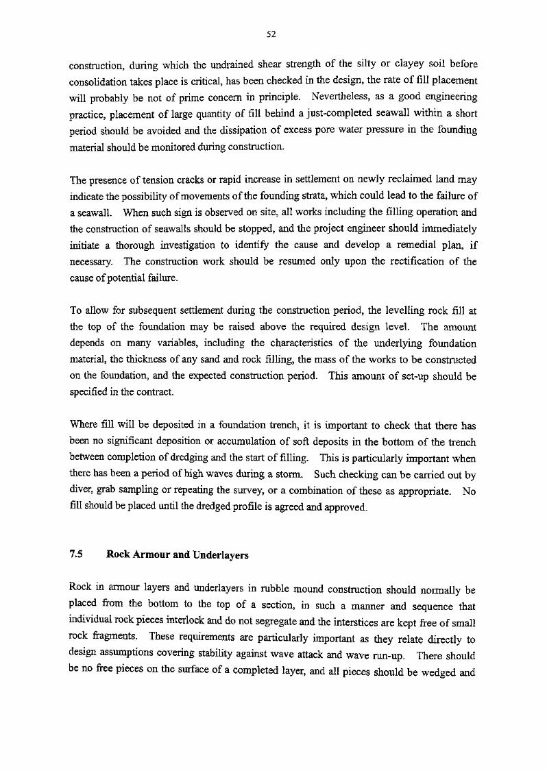
52
construction, during which the undrained shear strength of the silty or clayey soil before
consolidation takes place is critical, has been checked in the design, the rate of fill placement
will probably be not of prime concern in principle. Nevertheless, as a good engineering
practice, placement of large quantity of fill behind a just-completed seawall within a short
period should be avoided and the dissipation of excess pore water pressure in the founding
material should be monitored during construction.
The presence of tension cracks or rapid Increase In settlement on newly reclaimed land may
Indicate the possibility of movements of the founding strata, which could lead to the failure of
a seawall. When such sign is observed on site, all works including the filling operation and
the construction of seawalls should be stopped, and the project engineer should immediately
initiate a thorough investigation to Identify the cause and develop a remedial plan, if
necessary. The construction work should be resumed only upon the rectification of the
cause of potential failure.
To allow for subsequent settlement during the construction period, the levelling rock fill at
the top of the foundation may be raised above the required design level. The amount
depends on many variables, Including the characteristics of the underlying foundation
material, the thickness of any sand and rock filling, the mass of the works to be constructed
on the foundation, and the expected construction period. This amount of set-up should be
specified in the contract.
Where fill will be deposited in a foundation trench, it is Important to check that there has
been no significant deposition or accumulation of soft deposits in the bottom of the trench
between completion of dredging and the start of filling. This is particularly important when
there has been a period of high waves during a storm. Such checking can be carried out by
diver, grab sampling or repeating the survey, or a combination of these as appropriate. No
fill should be placed until the dredged profile is agreed and approved.
7.5 Rock Armour and Underlayers
Rock in armour layers and underlayers in rubble mound construction should normally be
placed from the bottom to the top of a section, in such a manner and sequence that
individual rock pieces interlock and do not segregate and the interstices are kept free of small
rock fragments. These requirements are particularly important as they relate directly to
design assumptions covering stability against wave attack and wave run-up. There should
be no free pieces on the surface of a completed layer, and all pieces should be wedged and

53
locked together so that they are not free to move without disturbing adjacent pieces in thesame layer.
Armour is the most important layer for the stability of the nibble mound. The armour layer
should be placed as soon as possible following the placement of underlayer to avoid damages
to these layers, which may be difficult to repair. It is advisable to keep a sufficient number
of rock armour in stock on site to ensure rapid placement in case of an unfavorable weather
forecast. Each armour should be placed individually, after inspection to ensure that it is
within the specified weight range, uncracked and of acceptable shape.
The core and underlayers are liable to damage by wave action during construction. If
continuous rough weather is expected, it may be necessary to cease work before the onset of
rough weather and provide temporary protection to the unfinished work. It is advisable to
limit the extent to which the core is constructed ahead of the underlayer, and the underlayer
ahead of the armour, to reduce the risk of storm damage and consequent delay.
For rock armour layers and underlayers above water level, final visual inspections from the
top of the slope and by boat from the bottom of the slope should be carried out in addition to
the normal profile check by survey. Below water level, a final visual inspection by diver is
recommended where possible, depending on visibility, particularly for rock armour layers.
If any significant holes or areas with infilled interstices are detected, whether above or below
water level, it will be difficult for these to be satisfactorily rectified without almost complete
reconstruction of the adjacent areas.
The method of survey should be agreed with the surveyor before the work starts to ensure
that readings are taken at truly representative points but that any high and low spots are also
identified. It should be noted that it is unable to fully control the thickness of armour layer
by sounding or levelling surveys. The number of rock for a stated area specified in the
drawings should therefore be checked to ensure adequate coverage and thickness of the
armour layer.
7.6 Concrete Armour
Concrete armour units are in general mass concrete and only occasionally contain
reinforcement. Opinions are divided on the effectiveness of reinforcement in armour units
as, if the steel corrodes, the adverse effect on durability can outweigh any advantages in using
it (BSI, 1991). High quality concrete should always be used, but caution should be

54
exercised on the use of high cement contents because of the risk of shrinkage cracking,
particularly with large armour units. Concrete mixes for large units should be designed to
reduce temperature differentials and moulds should be designed to avoid cracking of concrete
due to thermal stresses. Low heat cement is advisable. Concrete production, casting,
curing, stripping of formwork, delivery to stockyard, transporting and placing should be
arranged and programmed to minimize stresses. Sufficient number of armour units may be
kept on site to enable rapid placement to protect the underlayers and the core in case of an
unfavourable weather condition.
Concrete armour units may be placed randomly or in a regular pattern. They range from
massive approximately cubical units such as cubes to the more complex forms such as
Tetrapods and Dolosse. The massive types are intended to function in a way similar to
natural rock, while the more complex units depend upon the interlocking between units to
achieve the hydraulic stability. True random placing is difficult to achieve, and inevitably
results in some units not being as well interlocked as others. Although placing to a
predetermined layout is usually specified for interlocking units, this is also difficult to
achieve except under favourable conditions of good underwater visibility and calm seas.
The result may be a semi-random pattern. Specific recommendations on the placing method
should be checked with the originator or licensee.
Cracks resulting from stresses arising during construction, delivery and placement can
significantly reduce the capacity of the concrete armour units to resist wave loads and
therefore they should be handled with great care under close supervision. Full scale
dynamic loading tests can be carried out on site to check the impact resistance of the units.
These can take the form of drop tests in which a unit is dropped from varying heights onto a
concrete or rubble surface. Results of these tests have shown that the flexural strength may
be reduced by 60% after 6 to 10 impacts. Further information, including suggested
maximum sizes of concrete armour units, can be found in BS 6349:Part 7:1991.
The conditions of the concrete armour units should be closely checked on site. Cracked or
broken units should not be used as armour. A thorough inspection should be made on each
unit immediately before and after placing. Damaged units should be removed immediately
even though it has been placed on the slope.
7.7 Bermstones
Beraistones should be placed as soon as practicable to protect the toe of the structure against

55
scouring due to waves and currents. Early placement is particularly important when one ormore of the following conditions apply :
• The location is subject to strong currents.
• The location is exposed to wave attack.
• When works are carried out in season during which tropical storms may befrequent.
« The water depth in front of the structure is shallow.
Underwater inspection is important to ensure that bermstones have been placed over the
foundation width required and that the gap between bermstones are kept to the minimum.
7.8 Concrete Seawall Blocks
Precast blocks for concrete blockwork structures are normally made of mass concrete with a
characteristic strength of 20 MPa. The ease and accuracy of construction is dependent on
the accuracy of the shape and size of the blocks being used, and the accuracy and consistency
of the levelling stones on top of the foundation. It is important for the levels of the rails 01
other profile marks to be checked by surveyor before laying of the levelling stones starts, and
for the levelling stones to be inspected by diver before any block setting.
Daily records for the casting and setting of blocks should be kept. In addition, record
drawings giving the date of setting of each block should be kept in the site office. After the
setting of each layer of blocks has been completed, a diving inspection should be carried ou'
to check such matters as the accuracy of setting, joint widths, infilling of gaps betweer
adjacent blocks and cleanliness of the top surface for receiving the next layer of blocks.
7.9 Facing Stones and Copings
The construction of in-situ concrete copings and the pointing of facing stones of a seawal
should preferably be carried out as late as possible in the construction programme in order t<
allow for the effects of settlement. Subject to user requirements, the works of these tw<items may be delayed until towards the end of the construction period of a project.

56
7.10
Concrete caissons consist of open-topped cells prefabricated in the dry and are usually floated
to their final location for sinking onto prepared foundation in the seabed. Caissons are
generally of rectangular shape in plan and subdivided into cells for strength and for control of
stability during towing, sinking and filling when in the final position.
Filling should be carried out as soon as the caisson is positioned for the sake of stability.
For breakwaters, compartments are completely filled for stability under wave loading. For
seawalls, the seaward compartments may be better left either empty or partially filled to
adjust the overall centre of gravity and reduce bearing pressures if the front wall is not used
for vessel berthing. Fill compaction can be carried out to provide a secure foundation to the
superstructure. Lean concrete may be used in seawall compartment where necessary to
provide increased resistance to impact loads such as vessel berthing loads. The capping
should not be cast until the caissons have been filled. Scour protection against wave and
current actions should also be completed as soon as possible after placing of the caissons.
7.11 Joints for Seawall Caissons
Movement joints should generally be provided in the reinforced concrete capping of seawalls
at centres not exceeding 30 m. The capping should be effectively anchored to the wall and
to the counterforts.
Gaps between caissons for seawalls should generally be closed to prevent water movement
and to protect the bedding layer from scour by high velocity currents caused by wave action.
The joint seal on the seaward face should be made as close as practicable to the seaward face
to keep the depth of the gap between caisson walls to a minimum. Where storm wave action
is possible at any time during construction, the joint should be completed as soon as possible.
Key joints are sometimes necessary to transmit load between caissons to avoid relative
movement and should be capable of shear transmission of 25% of the maximum horizontal
load on either caisson to the adjacent unit (BSI, 1991). Except where caissons are placed on
a rock foundation, some relative settlement is likely to take place and joints should providefor vertical movement.
Where differential settlement between caissons is possible, the joint faces should be painted
with slip coat such as bitumen to avoid bond between the joint plug and the caissons. The

57
gap can be sealed at the face using a grout sock or tube, with tremie concrete being to
form the joint plug.

58

59
8.
8.1
This chapter gives general guidance on the provision of marine and maintenance facilities onseawalls and breakwaters.
8.2
Marine facilities should be provided on seawalls and breakwaters after consultation with the
Director of Marine and other users. Where there is berthing requirement, public landings,
handrails, ladders and covers may be required to facilitate cargo handling or passenger
loading and unloading. Fenders are normally provided at public landings; but for public
waterfronts and public cargo working areas, fenders are usually not required.
Depending on the cope or crest level, public landings should consist of intermediate landings
to cater for different tidal levels. To prevent passengers from walking on slippery surface,
rough cast finish with thickness of 25 mm should be provided on the landing steps. Capping
units should be provided on the top of the fenders to close the gap between the landing and
the vessel. Landings should be furnished with stainless steel handrails.
Use of timbers as fendering system is not environmentally friendly and not recommended.
If rubber fenders are used, general guidance can be found in Chapter 6 of Part 1 of the
Manual.
Bollards and mooring eyes are required to allow vessels to berth and moor against the
structure. Standard 10-tonne bollards at about 8 m to 10m centres are usually provided for
vessels up to 2000 t displacement tonnage. However, bollards of 30 t or higher may be
required, for example, in public cargo working areas, to cater for larger vessels. Mooring
eyes are provided on the vertical face of structures for mooring of small vessels with small
freeboard not practical to have mooring ropes fixed to a bollard. The mooring eyes should
be recessed into the structures so that they will not affect the movement of vessels induced by
waves and tidal variations.
Depending on the use of the structures, the following facilities should also be provided :
© Cranes and mechanical handling equipment.

60
« Area lighting.• Stainless steel handrails.
• Navigation light.
• Notice boards.
• Fire-fighting equipment.
• Water and electricity services.© Marine structure identification plate showing the marine structure number.
The marine structure number should be obtained from the Civil Engineering Department for
structures maintained by this department.
For walkway constructed on the crest of the structure but not designed for public access,
security measures and adequate notices should be provided to avoid misuse by the public.
8.3 Maintenance Facilities
Typical inspection and maintenance accessories to be provided on seawalls and breakwaters
include:
• Stainless steel catladders for access to vertical seawalls and breakwaters.
• Access steps, which may be in the form of precast concrete blocks, constructed
on the slope of rubble mound breakwaters or sloping seawalls, from low tide
level to the crest of the structures.
• Handrails and lifting hooks as appropriate.
Unlike conventional seawalls or breakwaters, structures with wave absoiption chambers
require a number of maintenance related considerations that designers should address in thedesign, as detailed below.
Due to the presence of perforations, the structural strength of the front panel is significantly
weaker than a solid wall. Hence, if the structure is to be used for berthing of vessels,
particular attention should be paid to the installation offenders in front of the structure and
the front panel should be checked against the berthing forces. For ease of maintenance, the
front panels may be designed to be readily removable. The construction of a short section
of conventional blockwork landing step or pier structure amid a long length of waveabsorption seawall may be required to meet the berthing requirement.

6!
The perforations on the structure may cause floating debris to be trapped inside the wave
chamber due to the effect of tidal and wave action. Adequate access and facilities should
therefore be provided for routine clearance work. A continuous walkway with anti-slip
finish cantilevered from the rear face of the wave chamber may be constructed as working
platform. Manholes should be specified for access to the walkway. Manhole covers
should be designed to be watertight and fixed by steel bolts designed to withstand the uplift
wave pressure acting on the top slab. To facilitate underwater inspection, openings should
also be provided at the cross wall of the structure. Suitable anchors and lifting hooks should
be provided for fastening of safety belts and for easy maneuvering of maintenance materials
within the wave chambers.
The actual requirements of maintenance facilities are dependent on the nature and type of the
structures and should be agreed with the maintenance authority.

62

63
9.
9.1
This chapter provides general guidelines on the design of marine structures that may be
associated with the construction of seawalls and breakwaters. These include pumphouses,slipways, ramps, outfalls, intakes and beacons.
9.2 Pumphoiises
9-2.1 General
Pumphouses covered by this Manual include sets of individual small units, interconnected
small units and larger units for installation of pumps to provide salt water for buildings suchas those for air-conditioning purposes.
9.2.2 Layout and Location
In the design and construction of pumphouses, the requirements of the size, layout, facilities
and fittings should be agreed in advance with the client. The following points should be
noted when selecting a site for a pumphouse :
• The intake should be remote from sewage outfalls and other sources of
contamination and debris, and also from salt water outlets which discharge
heated water.• The seabed should be sufficiently deep to accommodate the intake, after
allowance for silting.• The water in front of the intake should not be stagnant and the adjacent seawall
should not be used for berthing.
9.2.3 Structure and Design
Pumphouses normally consist of reinforced concrete units, precast where placed below water
level and cast in-situ above water level. To ensure that the units are watertight, it is
recommended that the design of all walls and base slabs in contact with seawall should be in
accordance with BS 8007 (BSI, 1987).

64
Pumphouse units are usually constructed as part of a seawall To avoid possible future
problems, It is important that the underlying ground Is consolidated, for example,
by preloading, before the setting of the pumphouse units. This Is particularly Important
where a pumphouse Is to be constructed as an extension to or Immediately behind an existing
seawall. The pumphouse units may be connected to the sea by Intakes formed in special
precast concrete blocks. To ensure satisfactory operation of the pumps In all tidal and wave
conditions, It Is recommended that the crown of the Intake should generally be at a level not
higher than-0.75 mPD.
For ease of construction and to minimize the number of joints, precast pumphouse units
should be individual self-contained units with walls formed to as high a level as possible,
subject to weight limitations, and preferably to a level between mean sea level and mean
higher high water level for harbour locations. For larger pumphouses, sets of units can be
Interconnected above the junction between the precast and in-situ concrete level. It Is usual
for precast pumphouse units to be cast on a waterfront site, lifted by crane, transported to the
pumphouse site by barge, and set In position by crane. For this method of construction, the
weight of an individual unit is limited by the lifting capacity of available plant; units within
the weight range of 500 kN to 1000 kN are relatively common. Another method of
construction Is for the unit to be launched on a slipway after casting, floated, towed to the
pumphouse site and set In position by crane or crane barge.
When using the construction method referred to above which Involves transport by barge, It
Is usual to test each unit at the casting yard for watertightness by filling the unit with water
and leaving it filled for at least 24 hours. Although this method of testing does not fairly
reflect normal water pressures during pumphouse operation, It Is far simpler and less
expensive than Immersing the unit in water. Whichever method of testing Is adopted, It Is
Important that, during the design stage, the test loading condition Is also checked, with the
reinforcement designed and detailed accordingly. Water or sand Is usually used as ballast
during the placing of the precast pumphouse units to guard against buoyancy. Such ballast
should not be removed until a careful design check is made on the buoyancy of the structure.
9.2.4 Ties
BS 8007 recommends that ties used to secure and align fonnwork should not pass completely
through any liquid-retaining part of the structure, unless effective precautions can be taken to
ensure water tightness after their removal. The ends of any embedded ties should have
cover equal to that required for the reinforcement. The gap left from the end of the tie to the
face of the concrete should be effectively sealed. Although it has been common practice to

65
provide central waterstops and keys at construction joints between the precast units and in-
situ concrete sections, BS 8007 states that waterstops are not usually required for construction
joints with complete continuity in water-retaining structure. Central waterstops can be
difficult to fix and held in position during concreting, and problems can be experienced when
placing and compacting concrete around the waterstop. Whether or not a central waterstop
is used, extreme care should be taken during surface preparation for construction joints inpumphouse unit walls.
9.2.5 Screens, Guides and Fittings
Pumphouse intake screen guides may be stainless steel or cast iron sections bolted onto the
outside of the concrete intake blocks, or formed directly as a recess in the concrete intake.
For the former case, the guides should be protected from damage by vessel impact using
securely fixed fenders. For the latter case, the concrete nib between the recess and the outer
face should be detailed with care, with stainless steel sections being used as necessary toprotect and line the recess.
Internal and external steel fittings and fixtures, such as ladders, gratings, guide covers and
runway beams, should be stainless, galvanized or painted with coal tar epoxy, as agreed with
the users. To protect the internal fittings and to guard against the entry of silt and other
deposits, a temporary stopper should be provided to block the intake pipe.
9.3 Slipways and Ramps
9.3.1 Location and Basic Dimensions
A slipway is a structure, consisting of a rail track, cradle and haulage device, used in ship
building and ship repair work for the movement of vessels to and from the sea. The cradle
is used to support the vessel and runs along the rail track, usually of standard flat-bottomed
rails in two, three or four parallel lengths. Wire ropes are usually used to haul the vessel by
means of a winch. Useful information on slipways is given by Grove & Little (1951).
Slipways should be located, where possible, at sites well protected from wave action. The
slipway dimensions will depend on the size of the largest vessel to be slipped; in general the
length of track above high water should exceed the vessel length, and the lower end of the
track should extend to a depth adequate to allow the cradle to clear the vessel at lowest tide.
The overall slipway width should be at least one and a half times the width of the largest

66
vessel, and the gradient of the track within the range of 1 In 10 to 1 In 25, with about 1 In 15
being normal.
9.3.2 Slipway
To a large extent, slipway design will depend on the method of construction. Construction
in the dry within a cofferdam may be more expensive In terms of Initial cost than construction
underwater, but will enable better quality of construction and tighter tolerances, resulting in a
significant reduction in likely long term maintenance costs. With piled foundations,
differential settlement will be controlled. With rubble mound foundations, it is essential that
pre-loading is carried out to limit future differential settlement. Track support beams should
be connected by cross-ties to maintain track gauge. Rail track fixing details should allow
for possible relevelling and realignment during the design life of the structure, and also
possible replacement of the upper lengths due to corrosion. Setting tolerances for line and
level will depend on the cradle design, but will normally be significantly tighter than for
general marine works. A tolerance of ± 10 mm for line and level is considered typical, but
is often difficult to achieve for underwater work.
For the design of the rail track support beams, the main problem relates to the assessment of
the load distribution as the vessel ceases to be waterborne and becomes carried on the loading
cradle. At the start of slipping, with the cradle at the bottom of the slipway, the vessel is
warped into position until bearing is obtained on the first section of the cradle. As slipping
commences, by hauling up the cradle, gradually more and more weight is taken by the first
section, and this load reaches the maximum just as the second section begins to take a share
of the weight. Thereafter, all sections progressively take some load until the vessel is clear
of the water and bearing uniformly over the whole cradle length. The exact value of the
maximum load bearing on the first section, or 'sue' load, depends on the draft and outline of
the vessel concerned, but as a guide can be taken to be about one third of the vessel weight.
Since the sue load is only effective over a relatively short length, it is unnecessary to design
the full slipway length for this load. The lowest length need only be designed to carry the
weight of the cradle plus vessel uniformly distributed. The intermediate length should be
designed for the full sue load or a proportion of the full sue load increasing from the lower
end to the full sue load at the upper end as appropriate.
Care should be taken in estimating the cross distribution of load. With a cradle carried on
two rails only, it is safe to regard the load as being equally divided between them, but where
three or four rails are involved, such an assumption is not recommended due to possible rail
settlement causing the cradle to carry loads unevenly. It is recommended that each rail
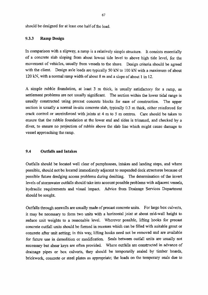
67
should be designed for at least one half of the load.
9.3.3
In comparison with a slipway, a ramp is a relatively simple structure. It consists essentially
of a concrete slab sloping from about lowest tide level to above high tide level, for the
movement of vehicles, usually from vessels to the shore. Design criteria should be agreed
with the client. Design axle loads are typically 50 kN to 100 kN with a maximum of about
120 kN, with a normal ramp width of about 8 m and a slope of about 1 in 12.
A simple rubble foundation, at least 3 m thick, is usually satisfactory for a ramp, as
settlement problems are not usually significant. The section within the lower tidal range is
usually constructed using precast concrete blocks for ease of construction. The upper
section is usually a normal in-situ concrete slab, typically 0.3 m thick, either reinforced for
crack control or unreinforced with joints at 4 m to 5 m centres. Care should be taken to
ensure that the rubble foundation at the lower end and sides is trimmed, and checked by a
diver, to ensure no projection of rubble above the slab line which might cause damage to
vessel approaching the ramp.
9.4 Outfalls Intakes
Outfalls should be located well clear of pumphouses, intakes and landing steps, and where
possible, should not be located immediately adjacent to suspended deck structures because of
possible future dredging access problems during desilting. The determination of the invert
levels of stormwater outfalls should take into account possible problems with adjacent vessels,
hydraulic requirements and visual impact. Advice from Drainage Services Department
should be sought.
Outfalls through seawalls are usually made of precast concrete units. For large box culverts,
it may be necessary to form two units with a horizontal joint at about mid-wall height to
reduce unit weights to a reasonable level. Wherever possible, lifting hooks for precast
concrete outfall units should be formed in recesses which can be filled with suitable grout or
concrete after unit setting; in this way, lifting hooks need not be removed and are available
for future use in demolition or modification. Seals between outfall units are usually not
necessary but shear keys are often provided. Where outfalls are constructed in advance of
drainage pipes or box culverts, they should be temporarily sealed by timber boards,
brickwork, concrete or steel plates as appropriate; the loads on the temporary seals due to

68
waves, water pressure and soil pressure should be assessed.
Intakes are usually formed in seawalls to provide seawater for pumping stations, and are
usually constructed concurrently with the seawalls. Size and location of the intake will be
determined by the client. The invert level should be designed to ensure a continuous supply
of water, unaffected by waves, tides, currents and water temperature variations. The usual
method of construction is to use precast concrete units for the base slab and lower walls, and
cast in-situ concrete for the upper walls and roof slab. Joints between precast concrete units
are usually required by the client to be sealed.
9.5 Beacons
Beacons include lit and unlit beacons located offshore, on the foreshore or rock outcrops and
on land, and navigation lights on marine structures. Lights can be mains- or battery-
powered as appropriate to the location and as required by the Director of Marine. A beacon
located offshore can either be a piled structure, similar to a dolphin in design, or a precast
reinforced concrete gravity structure with enlarged base and rubble foundation, depending on
the seabed conditions and water depth. Beacons located on the foreshore or rock outcrops
can usually be simple precast or cast in-situ concrete structures doweled to underlying sound
rock where possible. They will be topped with steel light posts for final light connection for
lit beacons, or simple steel/concrete marker posts for unlit beacons. Beacons located on
land and navigation lights on structures will generally only be subject to dead and wind loads,
and simple mass concrete foundations for the light posts or marker posts will usually beadequate.
Ladders, fenders and mooring eyes as appropriate should be provided for beacons located
offshore. Beacons located on the foreshore, rock outcrops and land should be provided with
landing facilities, either incorporated into the beacon structure or built separately. Fitting
and fixtures such as ladders, handrails and mooring eyes should be stainless steel. Steel
light posts and marker posts should preferably be galvanized and painted after fabrication.

69
REFERENCES
BSI (1986). Code of Practice for Foundations (BS 8004:1986). British Standards
Institution, London, 157p.
BSI (1987). Code of Practice for Design of Concrete Structure for Retaining Aqueous
Liquids (BS 8007:1987). British Standard Institution, London, 31p.
BSI (1991). Maritime Structures - Part 7 : Guide to the Design and Construction of
Breakwater (BS 6349:Part 7:1991). British Standards Institution, London, 88p.
CED (2003). Special Project Report No. SPR 1/2003 - Study on Coastal Subsoil
Geotechnical Conditions. Civil Engineering Office, Civil Engineering Department,
Hong Kong.
CETN (1988). Design of Rubble Foundation and Rubble Toe Protection (Coastal
Engineering Technical Note (CETN-III-39, 3/88)). US Army Corps of Engineers.
CIRIA (1991). Manual on the Use of Rock in Coastal and Shoreline Engineering (Special
Publication 83). Construction Industry Research and Information Association,
United Kingdom, 607p.
ETWB (2002). Environment, Transport and Works Bureau Technical Circular (Works) No.
34/2002 - Management of Dredged/Excavated Sediment. Environment, Transport
and Works Bureau, Hong Kong.
GCO (1984). Geotechnical Manual for Slopes. Geotechnical Control Office, Hong Kong.
GCO (1987). Guide to Site Investigation (Geoguide 2). Geotechnical Control Office,
Hong Kong, 365p.
GCO (1988). Guide to Rock and Soil Descriptions (Geoguide 3). Geotechnical Control
Office, Hong Kong, 191p.
GEO (1993). An Evaluation of the Suitability of Decomposed Granite as Foundation
Backfill for Gravity Seawalls in Hong Kong, GEO Report No. 33. Geotechnical
Engineering Office, Hong Kong.

70
GEO (2001). Model Specification for Soil Testing. Geotechnical Engineering Office,
Hong Kong, 39lp.
Goda Y. (2000). Random Seas and Design of Maritime Structures. World Scientific
Publishing Co Pte Ltd, Singapore, 443p.
Grove, G.C. and Little, D.H. (1951). The Design and Construction of some Slipways up to
1200 tons. The Institution of Civil Engineers Maritime Paper No. 17, 35p.
HKU (1998). Study of Inner Harbour Waves and their Reduction - Wave Loading
Determination for Wave Absorbing Seawalls. University of Hong Kong, 14p.
Hong Kong Government (1992). General Specifications for Civil Engineering Works.
Hong Kong Government, 3 volumes.
Mitchell J.K. and Katti R.K. (1981). Soil Improvement - State of Art Report. The tenth
International Conference on Soil Mechanics and Foundation Engineering,
Stockholm.
OCDI (2002). Japanese Technical Standards for Port and Harbour Facilities with
Commentary. Overseas Coastal Development Research Institute, Tokyo.
Suzuki Y. (1982). Deep Chemical Mixing Method using Cement as Hardening Agent.
Proceedings of the International Symposium on Recent Developments in Ground
Improvement Techniques, Bangkok, pp 299-340.
Tanimoto, K., Yagyu, T., and Goda, Y. (1982). Irregular wave tests for composite
breakwater foundations, Proc. 18th Int. Coastal Eng. Conf., ASCE, Cape Town, pp.2144-2163.
Tsinker, G.P. (1997). Handbook of Port and Harbour Engineering. Geotechnical and
Structural Aspects. International Thomson Publishing Asia, 1054p.
WB (1995). Works Branch Technical Circular No. 3/95 - Control of Wave Reflection inVictoria Harbour. Works Branch, Hong Kong.
WB (1999). Works Bureau Technical Circular No. 13/99 - Geotechnical Manual for
Slopes - Guidance on Interpretation & Updating. Works Bureau, Hong Kong.

71
Ye, S.L., Han, J. and Ye, G.B. (1997). Foundation Treatment and Underpinning Technology
(Second Edition). China Construction Industry Press. (In Chinese).

72

73
TABLES

74
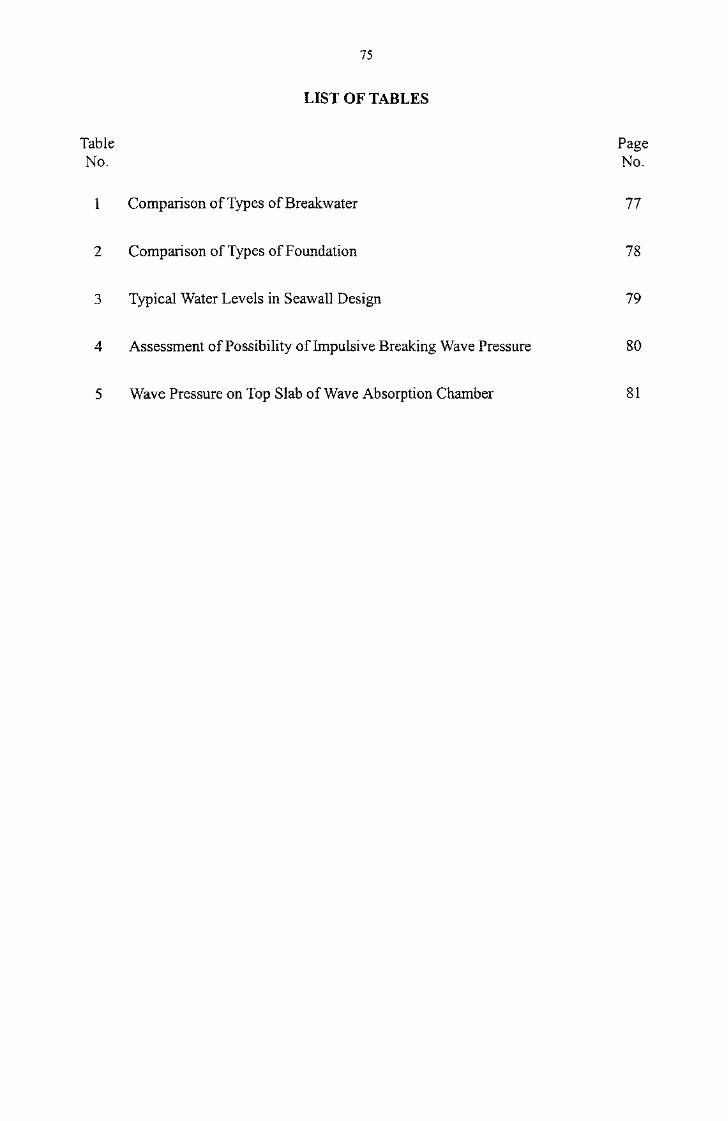
75
OF
Table PageNo. No.
1 Comparison of Types of Breakwater 77
2 Comparison of Types of Foundation 78
3 Typical Water Levels in Seawall Design 79
4 Assessment of Possibility of Impulsive Breaking Wave Pressure 80
5 Wave Pressure on Top Slab of Wave Absorption Chamber 81

76

1 Comparison of Types of
WaveReflection
Water Depth
Settlement
Berthing
ConstructionMaterials
ConstructionMethods
Maintenance
RubbleBreakwater
Rubble mound absorbspart of the waveenergy and reduces theamount of wavereflection.
A large rubble moundwill be required indeep water.
Able to toleratesettlement.
Berthing facilitiesshould be providedseparately.
Large quantity of rockshould be availableparticularly in deepwater.
Specialized plant is notnecessarily required.
Regular monitoring isrequired and repair isnecessary fordislocated armourunits.
VerticalBreakwater
Waves are nearly fullyreflected from thevertical face.
May not be practicableto design a verticalbreakwater to carry thewave loading in verydeep water.
A certain control onsettlement is required.
The vertical face of thestructure can allowvessel berthing.
May be suitable ifsufficient rock quantityis not available.
Specialized plant isrequired for deliveryand placing of caissons.
Repair is necessary fordamaged concrete.Monitoring ofdisplacement of uprightsection is required aftersevere storms.
CompositeBreakwater
Same as verticalbreakwaters.
May be suitable forvery deep water wherethe quantity of rockrequired for a rubblemound is not availableor when it is notpracticable to design avertical breakwater indeep water.
A certain control onsettlement is required.
Same as verticalbreakwater.
May be suitable in deepwater if sufficient rockquantity is not availablefor large rubble mound.
Same as verticalbreakwaters.
A combination ofrubble moundbreakwaters andvertical breakwaters.

78
2 of of
Methods PrinciplesProperties of
Soil Limitations
Dredging(Full orPartialDredging)
Marine mud or softalluvial deposit tobe totally orpartially removedand replaced bysuitable fillmaterial.
Marine mud or softalluvial deposit iscompletely orpartially replaced byfill of betterengineeringproperties.
The method is relativelysimple but problematic for soildisposal, in particular forcontaminated soil. Lessdredging for partial dredgingbut more detailed investigationand design, close monitoringas well as longer constructionperiod may be required.
DeepCementMixing
Lime and cementintroduced intonative soil throughrotating auger orspecial in-placemixer.
Solidified soil pilesor walls withrelatively highstrength.
No dredging involvednormally, no lateraldisplacement of native soil andno additional surcharge onunderlying soil. Stringentquality control required.Cannot work if largeobstruction is encountered.Study on possibleenvironmental impact required.
StoneColumns
Holes jetted intosoil and backfilledwith denselycompacted gravel.
Increased bearingcapacity and reducedsettlements.
Limited bearing capacityenhancement. Stringentquality control required. Noteffective for sensitive clay.Lateral and upwarddisplacement of soil. Maynot be applicable for soft soil.

79
3 Typical Water Levels In
LoadingConditions
Normal/Accident
Extreme
Wave Condition
Wave condition at tropicalcyclone signal no. 3 or
within the first few hours ofhoisting of tropical cyclone
signal no. 8
Wave condition at returnperiod of 100 years
Wave condition at returnperiod of 1 0 years
Wave condition at returnperiod of 50 years
Wave condition at returnperiod of 100 years
Still Water Levelin of Seawall
Sea water level atreturn period of 2 years
Sea water level at return periodof 2 years minus 0.7 m
Mean lower low water level
Sea water level atreturn period of 10 years
Sea water level at return periodof 10 years minus 1 .0 m
Sea water level atreturn period of 100 years
Sea water level at return periodof 100 years minus 1.0 m
Sea water level atreturn period of 50 years
Sea water level at return periodof 50 years minus 1 .0 m
Mean lower low water level
Ground WaterLevel
behind Seawall
Sea water level atreturn period of
2 years
Mean lower low waterlevel plus 0.7 m
Sea water level atreturn period of
10 years
Sea water level atreturn period of
100 years
Sea water level atreturn period of
50 years
Mean lower low waterlevel plus 1 .0 m
Notes : 1. The water levels for temporary loading conditions should be determined by designers.
2. The critical still water level may be some intermediate levels of the quoted water levels in this tableand should be assessed by designers for each case.
3. Designers should take into account the worst credible ground water conditions when determiningthe ground water levels behind the seawall. Hence, the design ground water level may be higherthan the levels given in this table.

80
Table 4 Assessment of Possibility of Impulsive Breaking Wave Pressure
A-l
A-2
A-3
A-4
A-5
A-6
B-l
B-2
B-3
Is the angle between the wave direction and the line normalto the breakwater less than 20°?
\J/Yes
Is the rubble mound sufficiently small to be considerednegligible?
\|/Yes
Is the sea bottom slope steeper than 1/50?
\|/Yes
Is the steepness of the equivalent deepwater wave less thanabout 0.03?
xj/Yes
Is the breaking point of a progressive wave (in the absenceof a structure) located only slightly in front of thebreakwater?
\|/Yes
Is the crest elevation so high as not to allow muchovertopping
NJ/Yes
Danger of Impulsive Pressure Exists
(Continued from A-2)
Is the combined sloping section and top berm of the nibblemound broad enough?
NJ/Yes
Is the mound so high that the wave height becomes nearlyequal to or greater than the water depth above the mound?
Y Yes
Is the crest elevation so high as not to cause muchovertopping?
^Yes
Danger of Impulsive Pressure Exists
>b Littlp Ofino-pr
NcS GntaP 1*s \J(J tu 13- I
^ T ittlr Flci-nrrnr^> jLiuic u anger
J^fc. T iff If* T^ITIO'P'T"
"•%. T iff 1p T^iTncrpr
No^> T ittlp "nnnorr^ J_ylLLIC/ i-Xtlll^CI
*%, T ittlp Tlnno-pr~^ i_/ 1 L Ll C LJ til 1 CI
>> T ittlp FS^-no-rrs> juimo udngcr
° '>> T ittlr Tl-rnarr
Source : Reproduced from "Random Seas and Design of Maritime Structures" by permission of Prof. Y. Goda.

81
5 Wave on Top of Wave Absorption Chamber
Extreme Condition(10-year Return Period)
Extreme Condition(100-year Return Period)
With Front Panel:
Maximum local uplift pressure
Average uplift pressure
Average overtopping pressure No overtopping
Without Front Panel:
Maximum local uplift pressure
Average uplift pressure
Average overtopping pressure No overtopping
Notes : 1. The wave pressure on the top slab is for reference only, and is determined from physical modeltesting of seawall with a wave absorption chamber and removable perforated front wall(HKU, 1998). The dimension of the wave chamber (measured between the inner face of thefront wall and the rear wall of the chamber) is equal to 3 m. The wave chamber is extended to adepth of-2.65 mPD.
2. The perforation ratio of the front wall with uniformly spaced circular perforation of 700 mm isabout 26%.
3. The surface and soffit levels of the top slab in the test are respectively +435 mPD and+3.65 mPD.
4. The still water level is +3.05 mPD in 10-year return period and +3.45 mPD in 100-year returnperiod.
5. The significant wave height is +0.81 m in 10-year return period and +1.31 m in 100-year returnperiod.
6. Caution should be exercised if these figures are adopted, as the extreme water levels and waveheights vary in different areas, and chamber dimensions, perforation layout and soffit level of topslab may be different.
7. p is the density of seawater.

82

83
FIGURES

84

85
OF
Figure PageNo. No.
1 Type of Breakwaters 87
2 Precast Concrete Armour Units 88
3 Vertical Seawalls 89
4 Rubble Mound Seawalls 90
5 Breakwater Layout 90
6 Diffraction Coefficients for Breakwater Gap (2 Sheets) 91
7 Diffraction Coefficients for Island Breakwater (2 Sheets) 93
8 Layout of Deep Cement Mixing Foundation 95
9 Layout of Stone-Column Foundation 96
10 External Forces on Soil Body Stabilized by Deep Cement Mixing 97
11 General Layout of Wave Absorption Seawall 97
12 Definition Sketch for Rubble Mound Breakwaters and Seawalls 98
13 Notional Permeability Factor 99
14 Typical Crest Structures for Rubble Mound Breakwaters 100
15 Toe Details for Rubble Mound Structures (2 Sheets) 101
16 Toe Protection 102
17 Falling Apron for Rubble Mound Structures 103

86
Figure PageNo. No.
18 Typical Breakwater Roundhead Construction 103
19 Stability Calculation for Vertical Seawalls 104
20 Stability Calculation for Vertical Breakwaters 105

Still water level
87
-Main armour
Foundation
(a) Rubble Mound Breakwater
Still water level gea
P/////////77/////////7777//.
ToeToe protection
Scour protection
Foundation \- Bedding layer
(b) Caisson Type Vertical Breakwater
Still water level gea
~\
\•Y////7/7///W/////////7,
Fill
J
\Fill
i Harbour
Rubble mound
Seabed
Foundation
(c) Composite Breakwater
Note:
1. Caisson type structure can be replaced by blockwork structure.
Figure 1 - Type of Breakwaters

88
Dolos Tetrapod
Cube Accropode
Stabit Antifer block
Figure 2 - Precast Concrete Armour Units

Concrete capping
Granite facing
-In-situ concretebacking
Berm stone
Filter
Precast seawall block
(a) Concrete Blockwork Seawall
V
A:Fill
mmm'
Fill
Foundation
(b) Caisson Seawall
caisson
Perforated front wall •
Underwater opening —
Foundation
(c) Wave Absorption Seawall
-Wave absorption chamber
Figure 3 - Vertical Seawalls

90
Filter layer(If reclamation fill is used
Underlayer/filter as core material, the filterlayer behind the core will
(a) Rubble Mound Seawall for Reclamation not be necessary)
Underlayer/filter
Existing soil
(b) Rubble Mound Seawall for Shore Protection
Figure 4 - Rubble Mound Seawalls
Shoreline
Accretion of sedimentat shore
Erosion of sediment from the shoreEroded shoreline
Harbour basin ortyphoon shelter
-Lee breakwater
-Main breakwater^/Prevailing wave direction
Longshore sediment transport direction
Figure 5 - Breakwater Layout

91
4.0B
3.0B
O.OB
4.0B
3.0B
O.OB-3.0B -2.0B -1.0B 1.0B 2.0B 3.0B
(a) Mean Incident Direction 0° (b) Mean Incident Direction 30°
4.0B
3.0B
2.0B
1.0B
O.OB
0.1
-3.0B -2.0B -1.0B 1.0B 2.0B 3.0B
45°
(c) Mean Incident Direction 45°
4.0B
3.0B
2.0B
1.0B
O.OB
O.f
iO.2
-3.0B -2.0B -1.0B 1.0B 2.0B 3.0B
60°
(d) Mean Incident Direction 60°
Notes:
1. Wave length corresponds to peak period of wave spectrum.
2. Length B = one wave length, Pierson-Moskowitz spectrum, cos2 directional spread.
Source: BS 6349 : Part 1 (2000) (Acknowledgement: HR Wallingford)
Figure 6 - Diffraction Coefficients for Breakwater Gap (Sheet 1 of 2)
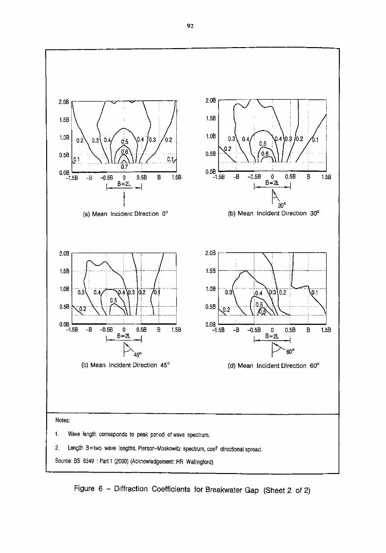
92
2.06
" -1.5B -B -0.5B 0 0.5B B 1.5Bi B=2L i
(a) Mean Incident Direction 0°
2.0B
1.5B
O.OB-1.5B -B -0.5B 0 0.5B B 1.5B
i B=2L .
30°(b) Mean Incident Direction 30°
2.0B
1.5B
1.0B
0.5B
O.OB
of 2 7of
-1.5B -B -0.5B 0 0.5B B 1.5Bi B=2L i
45°
(c) Mean Incident Direction 45°
O.OB-1.5B -B -0.5B 0 0.5B B 1.5B
B=2L i
(d) Mean Incident Direction 60°
Notes:
1. Wave length corresponds to peak period of wave spectrum.
2. Length B=two wave lengths, Pierson-Moskowitz spectrum, cos2 directional spread.
Source: BS 6349 : Parti (2000) (Acknowledgement: HR Wallingford)
Figure 6 - Diffraction Coefficients for Breakwater Gap (Sheet 2 of 2)

93
4.0B
3.0B
2.0B
1.0B
O.OB
4.0B
-3.0B -2.0B -1.0B 1.0B 2.0B 3.0BO.OB
(a) Mean Incident Direction 0°
-3.0B -2.0B -1.0B
(b) Mean Incident Direction 30°
4.0B
3.0B
2.0B
1.0B
O.OB-3.0B -2.0B -1.0B 1.0B 2.0B 3.0B
45°
(c) Mean Incident Direction 45°
4.0B
3.0B
2.0B
1.0B
O.OB1.0B 2.0B 3.0B-3.0B -2.0B -1.0B
(d) Mean Incident Direction 60°
Notes:
1. Wave length corresponds to peak period of wave spectrum.
2. Length B=one wave length, Pierson-Moskowitz spectrum, cos2 directional spread.
Source; BS 6349 : Part 1 (2000) (Acknowledgement: HR Wallingford)
Figure 7 - Diffraction Coefficients for Island Breakwater (Sheet 1 of 2)

94
2.0B
1.5B
l.OB
0.5B
O.OB-1.5B -B -0.5B 0 0.5B B 1.5B
i B=2L i
(a) Mean Incident Direction 0°
2.0B
1.5B
1.0B
0.5B
O.OB-1.5B -B -0.5B 0 0.5B B 1.5B
, B=2L
K30U
(b) Mean Incident Direction 30°
2.0B
1.5B
1.0B
0.5B
O.OB-1.5B -B -0.5B 0 0.5B B 1.5B
i B=2L ,
45°
(c) Mean Incident Direction 45C
2.0B
1.5B
1.0B
0.5B
O.OB-1.5B -B -0.5B 0 0.5B B 1.5B
i B=2L i
(d) Mean Incident Direction 60°
Notes:
1. Wave length corresponds to peak period of wave spectrum.
2. Length B=two wave lengths, Pierson-Moskowitz spectrum, cos2 directional spread.
Source: BS 6349 : Parti (2000) (Acknowledgement: HR Wallingford)
Figure 7 - Diffraction Coefficients for Island Breakwater (Sheet 2 of 2)
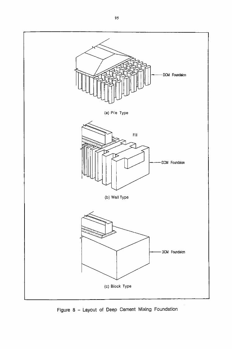
95
DCM Foundaion
(a) Pile Type
Fill
(b) Wall Type
DCM Foundaion
DCM Foundaion
(c) Block Type
Figure 8 - Layout of Deep Cement Mixing Foundation

V
Sea bed
Geotextile
Stone column
with decreasing
diameter with
increasing depth
(see note)
• Drainage blanket (granular material)
i— Geotextile
Notes :
1, Reduction of diameter with depth as shown, which is due to the increase in confining stress with depth, is for illustration purpose only. The actual amount of reductionwill depend on the strength-depth relationship of respective soil stratum.
2. This figure illustrates the general principle of stone columns only; details of the structure such as toe protection are not shown.
Figure 9 - Layout of Stone-Column Foundation

97
CD"O
Pa = Force due to active soil pressurePp = Force due to passive soil pressureT = Buoyancy forcePav = Skin frictionH = Horizontal load acting on a retaining structureV = Vertical loadR = Base frictionW = Weight of stabilized body
Figure 10 - External Forces on Soil Body Stabilized by Deep Cement Mixing
-Access manhole
Perforated front wall
Opening at crosswallof structure
Maintenance hook
Stainless steelsafety handrail
Inspection walkway
Catladder
Wave absorptionchamber
Foundation
Figure 11 - General Layout of Wave Absorption Seawall

98
(a) Breakwater
Filter layer(If reclamation fill is usedas core material, the filterlayer behind the core willnot be necessary)
(b) Seawall
Bb = Crest widthB = Top apron widthR c = Crest free boardt a = Thickness of armour layertu = Thickness of underlayera = Slope of structureh t & h1 = Extent of armour layer on slope
Note:
1. ht should extend down to the entire slope of the structure in shallow water where waves break.
Figure 12 - Definition Sketch for Rubble Mound Breakwaters and Seawalls

99
Dn50A/Dn50F =2
Dn50F/Dn50C = 4
(a) (b)
(d)
Dnsoc
Notional permeability factorNominal diameter armorNominal diameter filterNominal diameter core
Source: CIRIA (1991)
Figure 13 - Notional Permeability Factor

100
Armour Armour
Armour
Underlayer
Main armour
Underlayer
Source: BSI (1991)
(a) Simple Cap
2 units
Core
Irregular contact surface -1
(b) Minimum Crest Wall
2 units
Armour
Wave wall
Access road and services
Rear armour
Downstand
(c) Crest with Wave Wall
Figure 14 - Typical Crest Structures for Rubble Mound Breakwaters
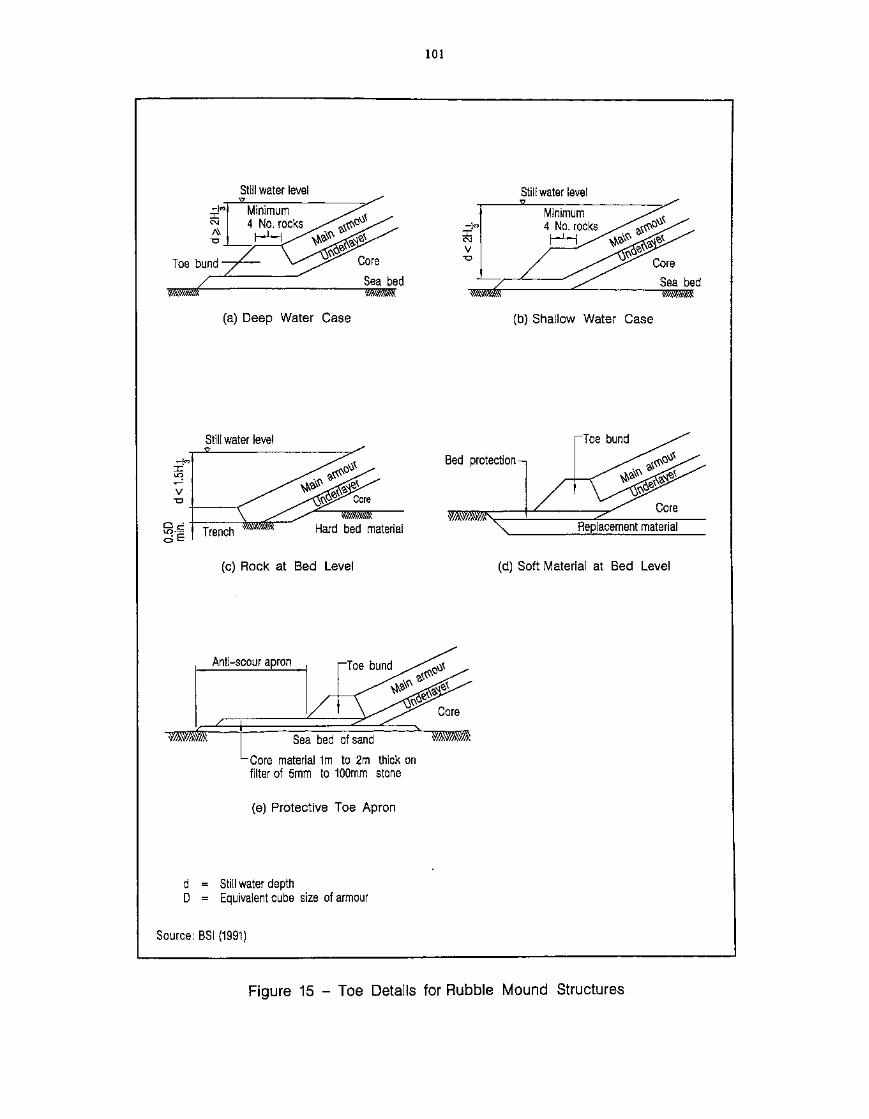
101
Still water level
Core
Sea bed
(a) Deep Water Case
Still water level
(b) Shallow Water Case
Still water level
Q cfuqo
Trench Hard bed material
(c) Rock at Bed Level
Bed protection-i
(d) Soft Material at Bed Level
Anti-scour apron
-Core material 1m to 2m thick onfilter of 5mm to 100mm stone
(e) Protective Toe Apron
d = Still water depthD = Equivalent cube size of armour
Source: BSI (1991)
Figure 15 - Toe Details for Rubble Mound Structures

102
W =w r h
N3(sH)3
B ^ 0.4dsB = 2H or 4 times size of rock
whichever is greater
H = Design wave height
wr = Unit weight of rock
/>rockSr
water
0.
LJ
o^>,(a) Rubble Toe Protection
-1-1x""y™ -y ^Y Y Y 7 Y "X.
yC^-i-s- y ^ s/- ^"sy ^-^ "^=7 "^^^
di '2
j^\ h ,>(f TT1 1 1, 7 1-, l^X^rX-XTT^^ '
ds
(b) Rubble Foundation
0.05 0.10 0.15 0.20 0.25 2B/L
10 12
where: K = parameter representing the combined effects of the relative water depth and the relative distancefrom the vertical wall on the maximum horizontal velocity at the bottom.
H = design wave height associated with depth ds
L = wavelength associated with the depth d.,ds = depth at structureB = toe apron width
Note:
1. For critical structures at open exposed sites where failure would be disastrous, and in the absence of reliable
wave records, the design wave height should be the Hy,00 during an extreme event at the structure corrected
for refraction and shoaling. If breaking might prevent the H^ wave from reaching the structure, the
maximum wave that could reach the structure should be taken for the design value of H. For less criticalstructures, design wave height could be taken between H^ and Hw
Source: CETN (1988) and Tanimoto et al (1982)
Figure 16 - Toe Protection

103
Main armour
Falling apron
(a) Original construction
Toe gives supportto main armour
Original bed level
(b) After scour has occurred
Source: BSI (1991)
Figure 17 - Falling Apron for Rubble Mound Structures
Harbour sideMain armour carriedaround head atreduced slope
Harbourentrance
Source: BSI (1991)
Figure 18 - Typical Breakwater Roundhead Construction

104
Sea
.SWL
q, q2 Land!i i i i
SWL
Pav=PasinB
ravrah
(a) Forces on a Seawall(Wave and water forces shown in (b) }
(b) Wave and Water Forces on a Seawall(Wave condition with wave troughat seaward face )
SLIDING FAILURE
Activating force Fa = Pah + lh - U2
Resisting force Fr = /LN where N=W+^V-U3
FOS against sliding = Fr /Fa
OVERTURNING FAILURE
Overturning momentResisting moment
eccentricity
FOS against overturning
M0 = Pahyp-PavB + U1yu1~U2yu2
M r =Wx w -U 3 x U 3
_ B M r,M0e =y--^-
= M r/M0
BEARING CAPACITY FAILURE
Effective normal load Qn =FOS against bearing capacity failure = Qujt / Q n
Notes :
1.2.
3,
5.6.7.
Other loads not indicated in the figure, if any, should also be taken into account.The total weight W includes the weight of the structure and that of the soil behind the structure up to thevirtual back.The soil pressure Pa includes the active pressure behind the virtual back due to soil and the surcharge liveload q2.Ui refers to the hydrostatic force exerting on the virtual back; U2 refers to the combined hydrostatic andwave pressure on the seaward face; Us refers to the uplift due to combined effect of buoyancy and wave.For details of Uj , U2 and U3 , see Port Works Design Manual: Parti - Figure 17.Live load q1 to be considered only for checking against bearing capacity failure; otherwise q.,=0.Coefficient of friction fi may be assumed to be 0.6 for both block /foundation and block /block interfaces.QU|t is the ultimate bearing capacity,
Figure 19 - Stability Calculation for Vertical Seawalls

105
Sea
SWL
X w u Shelteredwater
SWL
(a) Forces on a Breakwater(Wave and Water forces shown in (b))
SLIDING FAILURE
Activating force Fa = UwiResisting force Fr =//,N where N=W4J34Jw2
FOS against sliding = Fr /Fa
OVERTURNING FAILURE
Overturning momentResisting moment
eccentricity
(hydrostatic forces Ui =U2 assumed)
(b) Wave and Water Forces on a breakwater(Wave condition with crest at the seawardface and calm sea condition at thesheltered side )
M0 =
Mr = Wxw-U3xu 3
BN
FOS against overturning = M r/M0
BEARING CAPACITY FAILURE
Effective normal load Qn = N + qBFOS against bearing capacity failure = Q u i t /Qn
Notes :
1. Other loads not indicated in the figure, if any, should also be taken into account.2. The total weight W includes the weight of the structure.3. U-j and U2 refer to the hydrostatic forces exerting on the seaward face and sheltered face respectively
(U-i = U2 assumed); U3 refers to the buoyancy force; Uwi and UW2 refer to the horizontal force anduplift due to the waves at the seaward side. For details of Uw1 and Uw2 , see Port Works Design ManualParti - Figures 15 and 16.
4. Live load q to be considered only for checking against bearing capacity failure; otherwise q = 0.5. Coefficient of friction [L may be assumed to be 0.6 for both block /foundation and block / block
interfaces.6. QU|t is the ultimate bearing capacity.
Figure 20 - Stability Calculation for Vertical Breakwaters

106

107
APPENDIX A
MARINE GROUND INVESTIGATIONIN DIFFICULT GROUND AREAS

108
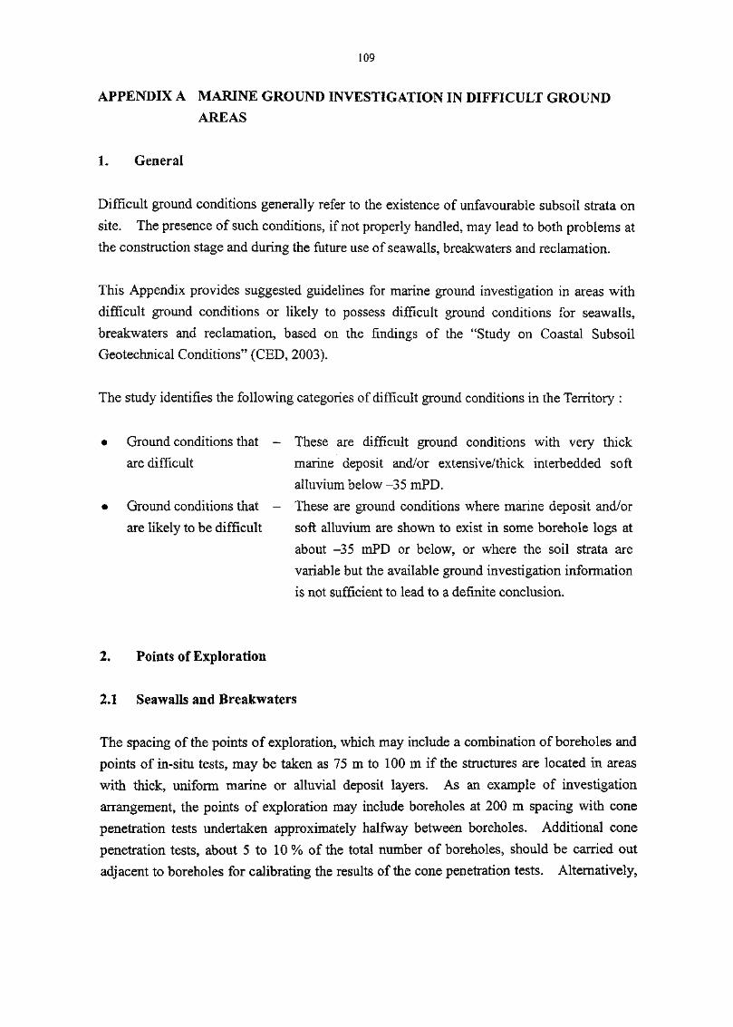
109
A IN
AREAS
1. General
Difficult ground conditions generally refer to the existence of unfavourable subsoil strata on
site. The presence of such conditions, if not properly handled, may lead to both problems at
the construction stage and during the future use of seawalls, breakwaters and reclamation.
This Appendix provides suggested guidelines for marine ground investigation in areas with
difficult ground conditions or likely to possess difficult ground conditions for seawalls,
breakwaters and reclamation, based on the findings of the "Study on Coastal Subsoil
Geotechnical Conditions" (CED, 2003).
The study identifies the following categories of difficult ground conditions in the Territory :
• Ground conditions that - These are difficult ground conditions with very thick
are difficult marine deposit and/or extensive/thick interbedded soft
alluvium below -35 mPD.
• Ground conditions that - These are ground conditions where marine deposit and/or
are likely to be difficult soft alluvium are shown to exist in some borehole logs at
about -35 mPD or below, or where the soil strata are
variable but the available ground investigation information
is not sufficient to lead to a definite conclusion.
2. Points of Exploration
2.1 Seawalls and Breakwaters
The spacing of the points of exploration, which may include a combination of boreholes and
points of in-situ tests, may be taken as 75 m to 100 m if the structures are located in areas
with thick, uniform marine or alluvial deposit layers. As an example of investigation
arrangement, the points of exploration may include boreholes at 200 m spacing with cone
penetration tests undertaken approximately halfway between boreholes. Additional cone
penetration tests, about 5 to 10 % of the total number of boreholes, should be carried out
adjacent to boreholes for calibrating the results of the cone penetration tests. Alternatively,

no
cone penetration tests undertaken halfway between the boreholes may be replaced by
boreholes as appropriate to the site conditions.
If interbedded soft deposits are expected, the spacing of the points of exploration may be
further reduced to 50 m or less in order to identify the locations and extents of the soft
material. The investigation may include boreholes at 100 m spacing with cone penetration
tests undertaken approximately halfway between boreholes. Similarly, additional cone
penetration tests, about 5 to 10 % of the total number of boreholes, should be carried out
adjacent to boreholes for calibrating the results of the cone penetration tests. Cone
penetration tests undertaken halfway between the boreholes may be replaced by boreholes as
appropriate to the site conditions.
At locations where highly variable soft deposits exist and where the soil strength is critical to
the stability of structures, the double-hole sampling approach may be considered. A
borehole is first sunk to obtain continuous profile of the soil strata for inspection and a second
borehole adjacent to the first borehole is then sunk to undertake vane-shear tests at close
intervals to ascertain the type, nature and strength of the soil. Attention should be paid to
locate the second borehole at a sufficient distance away from the first borehole to avoid
testing the disturbed ground caused by the drilling of the first borehole. Additional
boreholes should be sunk if the collected information is not sufficient to ascertain the ground
conditions.
2.2 Reclamation
The spacing of the points of exploration, which may include a combination of boreholes and
points of in-situ tests, may be taken as 100 m, if interbedded soft deposits are expected in the
subsoil profiles. As an example of investigation arrangement, the points of exploration may
include boreholes at 200 m spacing with cone penetration tests undertaken approximately
halfway between boreholes. Additional cone penetration tests, about 5 to 10 % of the total
number of boreholes, should be carried out adjacent to boreholes for calibrating the results of
the cone penetration tests. Alternatively, cone penetration tests undertaken halfway between
the boreholes may be replaced by boreholes to suit the site conditions. Additional boreholes
should be sunk if the collected information is not sufficient to ascertain the ground
conditions.
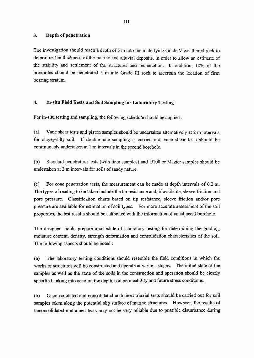
Ill
3. of
The investigation should reach a depth of 5 m into the underlying Grade V weathered rock to
determine the thickness of the marine and alluvial deposits, in order to allow an estimate of
the stability and settlement of the structures and reclamation. In addition, 10% of the
boreholes should be penetrated 5 m into Grade III rock to ascertain the location of firmbearing stratum.
4. In-situ Field Tests and Soil Sampling for Laboratory Testing
For in-situ testing and sampling, the following schedule should be applied :
(a) Vane shear tests and piston samples should be undertaken alternatively at 2 m intervals
for clayey/silty soil. If double-hole sampling is carried out, vane shear tests should be
continuously undertaken at 1 m intervals in the second borehole.
(b) Standard penetration tests (with liner samples) and U100 or Mazier samples should be
undertaken at 2 m intervals for soils of sandy nature.
(c) For cone penetration tests, the measurement can be made at depth intervals of 0.2 m.
The types of reading to be taken include the tip resistance and, if available, sleeve friction and
pore pressure. Classification charts based on tip resistance, sleeve friction and/or pore
pressure are available for estimation of soil types. For more accurate assessment of the soil
properties, the test results should be calibrated with the information of an adjacent borehole.
The designer should prepare a schedule of laboratory testing for determining the grading,
moisture content, density, strength deformation and consolidation characteristics of the soil.
The following aspects should be noted :
(a) The laboratory testing conditions should resemble the field conditions in which the
works or structures will be constructed and operate at various stages. The initial state of the
samples as well as the state of the soils in the construction and operation should be clearly
specified, taking into account the depth, soil permeability and future stress conditions.
(b) Unconsolidated and consolidated undrained triaxial tests should be carried out for soil
samples taken along the potential slip surface of marine structures. However, the results of
unconsolidated undrained tests may not be very reliable due to possible disturbance during
112
sampling. Hence, they should be used to supplement the in-situ strength obtained from the
field tests. Consolidated undrained tests can simulate the long-term performance of the soil
samples and their results can be used to assess the long-term stability of the structures. In
view of the comparatively poor consolidation characteristics of clayey/silty soil, care should
be exercised in adopting the consolidated undrained test results in the analysis of short-term
stability. In-situ vane shear test results should be used for such analysis as far as possible.
(c) Oedometer tests should be carried out for soil left below the foundation of structures
and reclamation. The number and Interval of the samples to be tested should be determined
according to the variability of the subsoil profiles, the layout of the foundation as well as the
extent of dredging or soil treatment works.
5,
CED (2003). Special Project Report No. SPR 1/2003 - Study on Coastal Subsoil
Geotechnlcal Conditions. Civil Engineering Office, Civil Engineering Department,
Hong Kong.

113
APPENDIX B
ASSESSMENT OF HYDRAULIC PERFORMANCE

114

115
CONTENTS
PageNo.
Title Page 113
Contents 115
B.I General 117
B.2 Wave Run-up 117
B.3 Wave Overtopping 118
B.3.1 Armoured Rubble Slope 118
B.3.2 Vertical Structures 119
B.4 Wave Reflection 120
B. 5 Wave Transmission 122
B. 6 References 122
List of Tables 125
List of Figures 129

116

117
APPENDIX B OF
B.I General
This appendix discusses some methods of assessing run-up, overtopping, reflection and
transmission due to waves on a structure. These methods are empirical based on simplified
configurations and should not be regarded as exhaustive. The results of calculations should
only be treated as quick estimate of the order of magnitude of the hydraulic parameters.
Further details of these methods can be found in Besley (1999), CIRIA (1991) and
Goda (2000). Where complicated situations are encountered, or if more accurate results
are required, physical model tests should be carried out to determine the hydraulic
performance of the structure.
B.2 Wave Run-up
For simple armoured rubble slopes. Van der Meer (1988) has given prediction formulae for
rock slopes with an impermeable core having permeability factor P = 0.1 and porous mounds
of relatively high permeability given by P = 0.5 and 0.6. The prediction formulae are :
Rui/Hl/3=a£m for £,<1.5
Rui'Hm=btmc for £,>1.5
The run-up for permeable structures (P > 0.4) is limited to a maximum :
where Rvi = Run-up at z % exceedance level (m).
Hl/3 = Significant wave height (m).
%m = Surf similarity parameter based on mean wave period = tan a I [s^ .
a — Average slope angle (degree).
sm = Offshore wave steepness based on mean wave period = 2nHm I gTm2 .
Tm = Mean wave period (s).
Values of the coefficients a , b, c and d for exceedance levels off equal to 1%, 2%, 5%, 10%

118
and significant run-up levels are given in Table Bl.
When subject to oblique waves, the wave run-up behaviour will be different for short-crest
waves and long-crested waves (CIRIA, 1991). For short-crested waves, the run-up is
maximum for normal incidence and the reduction of run-up for large wave angles is not more
than a factor of 0.8 compared with normal incidence. For long-crested waves, the increase
in run-up is only present when the incident wave angle is about 10 to 30 degrees.
B.3 Wave Overtopping
B.3.1 Armoured Rubble Slope
Owen (1980) has derived the following formulae to estimate the mean overtopping discharge
for rough impermeable and rough permeable structures :
5) (0.05 <**< 0.30)
*/r)
Q = Q*TmgHl/3
where Rc = Freeboard between still water level and crest of structure (m).
Hl/3 = Significant wave height at the toe of the structure (m).
Tm = Mean wave period at the toe of the structure (s).
r = Roughness coefficient given in Table B2.
g = Acceleration due to gravity (m/s2).
A,B = Empirical coefficients dependent on cross-section (see Table B3).
Q = Mean overtopping discharge rate per metre run of seawall (m3/s/m).
(X = Dimensionless mean overtopping discharge.
J?* = Dimensionless freeboard.
For a permeable crest, a reduction factor Cr may be applied to the overtopping discharge ascalculated above (Besley, 1999) :
Cr = 3.06exp(-1.5Cy//1/3)
where Cw = Crest width of the structure (m).
lfCw/HV3 is less than 0.75, Cr may be assumed as 1.

119
If the incident waves are not normal to the structures, the overtopping rate may further bemultiplied by a reduction factor Or (Besley, 1999) :
Or = I- 0.0001 52 J32
where J3 = Angle of wave attack to the normal, in degrees.
The formula is valid for 0° < J5 < 60° . For angles of approach greater than 60°, it issuggested that the result for [3 = 60° be applied.
B.3.2 Vertical Structures
When the toe of a vertical structure is close to the seabed level, the overtopping rate may be
estimated using the diagrams in Figures Bl and B2 (Goda, 2000). These diagrams are
compiled by Goda from the results of a series of random wave tests with allowance of wave
deformation in the surf zone. Equivalent deep water wave steepness of 0,012, 0.017 and
0.036, and seabed slopes of 1/10 and 1/30 are covered.
Besley (1999) also suggests method for calculating the amount of wave overtopping
discharge for vertical walls, which is given in the following paragraphs.
Reflecting waves predominate when d*> 0.3, in which case the following equation applies :
Q* = 0.05 exp (-2.78 Rc /HV3) (Valid for 0.03 < Rc IHW < 3 .2)
where d* = Dimensionless depth parameter.
d = Water depth at the toe of the structure (m).
Hl/3 = Significant wave height at the toe of the structure (m).
g = Acceleration due to gravity (m/s2).
Tm = Mean wave period (s).
(/ = Dimensionless discharge.Q = Mean overtoping discharge rate per metre run of seawall (m3/s/m).
Rc = Freeboard (height of crest of the wall above still water level) (m).
If the incident waves are at an angle to the normal of the seawall,

120
Q# = 0.05 exp {(-2.78/y ) (Rc/Hl/3)}
y is the reduction factor for angle of incident waves and is given by :
y = 1 - 0.0062,0 for 0° < 0 < 45°
y =0.72 for /?>45°
where 0 = Incident wave angle relative to the normal, in degrees.
Impact waves predominate when J*< 0.3, in which case the following equation applies :
Qh = 0.000137J?,-3-24 (Valid for 0.05<RA<1.00)
where Qh = Dimensionless discharge = {Q/(gh3)°'5}/d*2
Rh = Dimensionless crest freeboard = (Rc/Hl/3) d*
No data is available to describe the effect of oblique wave incidence on the mean discharge
when waves are in impacting mode.
B.4 Wave Reflection
There are various formulae for the coefficient of wave reflection of armoured slopes. It will
be useful to compare the results of these formulae when assessing the coefficient of reflection
of rubble mound structures.
For a rough permeable slope, the following formula was given by Seelig and Ahrens
(CIRIA, 1991) to estimate the coefficient of reflection :
where %p = Surf similarity parameter based on peak wave period.
Cr = Coefficient of reflection.
a = 0.6 and b = 6.6 for a conservative estimate of rough permeable slopes.
Postma (1989), taking into account Van der Meer (1988) data for rock slopes and Seelig and

121
Arhens formula, derived the following formula for Cr
0.73Cr = 0. 14£ ' with standard deviation of C = 0.055
Postma also treated the slope angle and wave steepness separately and derived
relationship :
Cr = 0.07 IF"0'082 (cot a)~0-62sp~°M with standard deviation of Cr = 0.036
where P = Notional permeability factor.
a = Slope of structure face.
sp = Offshore wave steepness based on peak wave period.
The results of random wave tests by Allsop and Channell (1989), analyzed to give values for
the coefficients a and b in Seelig and Ahrens formula, but with %m instead of £ , are shown
below. The slopes used armour rock in one or two layers with an impermeable slope
covered by underlay er rock equivalent to notional permeability factor P equal to 0.1 :
Rock, 2-layer a = 0.64 b = 8.85Rock, Mayer a = 0.64 b = 7.22
The range of wave conditions for which the coefficients may be used is given by :
0.004< sm<0.052 and Q.6<Hl/3/(ADn50)<1.9
where sm = Offshore wave steepness based on mean wave period.
Ai50 = Nominal rock diameter equivalent to that of a cube.
A = Relative mass density.
= (mass density of rock/mass density of seawater) - 1
Postma (1989) also reanalyzed the data of Allsop and Channell and modified his previous
formula for coefficient of reflection as follows :
Cr = 0. 1 25£ °"73 with standard deviation of Cr = 0.060

122
For structures with no-porous and steep faces, approximately 100% of the wave energy
incident on the structure will be reflected.
B.5 Wave
Van der Meer (1990) re-analysed the hydraulic model test results of various researchers and
suggested a prediction method for wave transmission :
Range of Validity Equation
-2.00 <Rc/Hl/3<-l.l3 Cf = 0.80-1.13<RC/H1/3<1.20 Ct = OA6-0.3Rc/Hl/3
l.2Q<Rc/Hl/3<2.QQ C, = 0.10
These formulae give a very simplistic description of the data available but will usually be
used for preliminary estimate of the performance.
For the range of low wave heights compared to rock diameter and Rc/ffl/3>l9 Ahrens (1987)
gave a formula relating the coefficient with wavelength, rock size and cross-sectional area of
the structure :
C, - 1.0/(LO+Z°-592) forRc/H}/3> I
where X = Hl/3At /(LpD2
n5Q)
At = Cross-sectional area of structure
Lp = Local wave length
B.6 References
Allsop, N.W.H. and Channell, A.R. (1989). Wave Reflections in Harbours : Reflection
Performance of Rock Armoured Slopes in Random Waves. Report OD 102.
Hydraulics Research Ltd, Wallingford.
Ahrens, J.R (1987). Characteristics of Reef Breakwaters. Technical Report CERC-87-17.
US Army Corps of Engineers, Coastal Engineering Research Centre, Vicksburg.
Besley, P. (1999). Overtopping of Seawalls, Design and Assessment Manual, R&D

123
Technical Rport W 178. Hydraulics Research Ltd, Wallingford.
CIRIA (1991). Manual on the Use of Rock in Coastal and Shoreline Engineering.
Construction Industry Research and Information Association, United Kingdom,
907p.
Goda, Y. (2000). Random Seas and Design of Maritime Structures. World Scientific
Publishing Co Pte Ltd, Singapore, 443p.
Owen, M.W. (1980). Design of Seawalls allowing for Wave Overtopping. Report Ex 924.
Hydraulics Research Ltd, Wallingford.
Postma, G.M. (1989). Wave Reflection from Rock Slopes under Random Wave Attack.
Delft University of Technology.
Van der Meer (1988). Rock Slopes and Gravel Beaches under Wave Attack. Doctoral
thesis. Delft University of Technology.
Van der Meer (1990). Data on Wave Transmission due to Overtopping. Report H986.
Delft Hydraulics.

124

125
OF
Table PageNo. No.
B1 Wave Run-up Coefficients 127
B2 Roughness Coefficients 127
B3 Wave Overtopping Coefficients 127

126

Bl Wave
127
ExceedanceLevels i
1%
2%
5%
10%
Significant
a
1.01
0.96
0.86
0.77
0.72
b
1.24
1.17
1.05
0.94
0.88
c
0.48
0.46
0.44
0.42
0.41
d
2.15
1.97
1.68
1.45
1.35
Note : These are coefficients used in the Van der Meer wave run-up prediction formulae.
Table B2 Roughness Coefficients
Type of Slope
One layer of rock armour on impermeablebase
One layer of rock armour on permeablebase
Two layers of rock armour
Roughness Coefficient r
0.80
0.55 - 0.60
0.50-0.55
Table B3 Wave Overtopping Coefficients
Front Face Slope of Structure
1 : 1
1 : 1.5
1 :2
1 :2.5
1 :3
1 :3.5
1 :4
A
0.00794
0.00884
0.00939
0.0103
0.0109
0.0112
0.0116
B
20.1
19.9
21.6
24.5
28.7
34.1
41.0

128

129
LIST OF FIGURES
Figure PageNo. No.
B1 Prediction of Overtopping Rates for Vertical Structures 131Seabed Slope 1/10
B2 Prediction of Overtopping Rates for Vertical Structures 132Seabed Slope 1/30

130

131
8=1:10
(b)H0'/L0 = 0.017
5 10"3 2 5 10~2 2 5 1CT1
q(m3/m-s
-0.5 0 0.5 1.0 1.5
d/H0'
Legend :q = overtopping rate
H0' = equivalent deep-water wave height
L0 = deep-water wavelength corresponding to significant wave
hc = height of top of wall above still water level
s = seabed slope (tangent of angle relative to horizontal)
Source : Goda (2000)
period i.e. L0 - gTs2/27r
Figure B1 - Prediction of Overtopping Rates for Vertical Structures- Seabed Slope 1/10

132
210 ~2
5
2
j-"o
i 25
2
5
2
2io-2
5
2
1 5
\; 2cr 10"
4
5
2io-5
5
2
2io-2
5
2
I 15
\ 2
5
210"5
5
2io-6
Legend :q = overtopH0' = equiva!L o = deep-vhc = heights = seabeo
Source : Goda (
~*^
s
^
<;
7/1ill
^. <yp
j \* <
^
^<~"
y/
*^7— "•*
^
8*1:30 d
fq'
*— ss
" -v
" s
-x
-x
N
X^N
^\
L\
*»~
(a)H0VL0=0.012
-0.5 0 0.5 1.0 1.5d/H0'
— - -- •*"
X^
y/'
'/!,
Ill:
f^-,Y//
j /i /
jrtCQSr
/\tf -.
N.
\
\ \
\
1 1
X
v \v \\ >
A
0.?^**1 H tM
\
ww,ru2 3 4 5 6 i
— "* —
.— • — •
^--
^
s=1:30 d
/ (b)H0/L0=
-0.5 0 0.5 1.0 1.5d/H0'
/7 ,
s
A
^///i l l
/ // 1
'1:1.
M'
fe1 / '
' /
^'^
?'^
3__
""X
^s
N\
^N
\
s\. \
X
\
\
\
f^^.
L_
0.017
c/xL
\
\s
\
Ho'-"
^\
\v \
\
0.
h
1n
2 3 4 5 6 £
«••*"""""
^^ '
^*~
8-130 d.
' /(c) H07 L0=
-qr
x
~N" \
•NI
Xs
\
\
\
l_
•*> he
t\
0.036
\\
\~N
/
%^'&
',y
//'/,//?Y,%fa
'/
*/'/>y/
f /
1
//
^
*
J 10 10^2 5 10^2 5 10"22 5 10q(m3/m-s)
}>,
bk
/
•%
V,#',**y
/
^^ /
?'/?
V
Yy
f/
/ /
W
//'/'y
210-2
5
2
10"3
5
2
5
210'5
5
2
1 10-6
r1
2io-2
5
2
5
2ID"4'5
2io-5
5
2
-*o
•or
~ oX
*-»\CT
5 10 10^2 5 10^2 5 10'22 5 1CT1 IU
q(m3/m-s)
/HQ' = o.5_
-^
s\
0.75
_1.0
, 1,25^isr
%"^
/
%/ /
-*
%'
»~ -
/
/s
</
i
/y,%
N<
?fa',v
*/Y'/,
/ $>&'/A
/
fy
t
T
2io-2
5
i-i5 |
2 '
5
2
5
2
^X
g
" — >"-o-
-0-5 0 0.5 1.0 1.5 2 3 4 5 6 8 10 10^2 5 10"3 2 5 10"22 5 1(T1 '"
d/Ho cj ( rn3/nv s)
jping rateent deep-water wave height/ater wavelength corresponding to significant wave period i.e. L0 = gT s
2 /277-of top of wall above still water level
slope (tangent of angle relative to horizontal)
2000)
Figure B2 - Prediction of Overtopping Rates for Vertical Structures- Seabed Slope 1/30
133
APPENDIX C
DETERMINATION OF SIZE OF ARMOUR

134
135
CONTENTS
PageNo.
Title Page 133
Contents 135
C.I General 137
C.2 Hudson Formula 137
C.3 Van der Meer Formulae 138
C.4 References 140
List of Tables 141

136

137
APPENDIX C DETERMINATION OF SIZE OF ARMOUR
C.I General
This appendix discusses the Hudson Formula and the Van der Meer Formulae for calculatingo
the size of rock armour of nibble mound structures.
C.2
The Hudson formula was derived from a series of regular wave tests using breakwater models.
The formula is given by :
where W = Weight of an armour unit (N).
H = Design wave height at the structure (m).
KD = Dimensionless stability coefficient.
a = Slope angle of structure.
pr = Mass density of armour (kg/m3).
g = Acceleration due to gravity (m/s2).A = Relative mass density of armour = ( p r / pw) - 1
pw = Mass density of seawater (kg/m3).
pr and pw may be taken as 2600 kg/m3 for rock and 1025 kg/m3 for seawater respectively
for design purposes.
For non-breaking wave conditions, the design wave height may be taken as Hl/lQ at the site of
the structure. For conditions where Hl/lo will break before reaching the structure, the wave
height used in design should be the breaking wave height or the significant wave height,
whichever has the more severe effect (BSI, 1991).
Suggested values of KD for rock armour at the trunk and head of structures under non-
breaking and breaking wave conditions can be found in BS6349:Part 7:1991 (BSI, 1991).
These quoted values do not take account of the differences in factors such as wave period and
spectrum, shape of armour rock, placement method, interlocking, angle of wave incidence,
size of underlayer and porosity which will have influence on the stability. They should not

138
be used without careful reviews of the factors involved.
C.3 Van der Meer Formulae
Van der Meer derived two formulae for plunging and surging waves. These formulae take
account of the influence of wave period, storm duration, armour grading, spectrum shape,
groupiness of waves, core permeability and damage level on rock armour, and therefore they
are described as practical design formulae for rock armour. The formulae are (BSI, 1991):
For plunging waves,
H \0.2
For surging waves,
H
where H = Design wave height, taken as the significant wave height (m).
DnSQ = Nominal rock diameter equivalent to that of a cube (m).A = Relative mass density of armour = ( pr I pw ) - 1
P = Notional permeability factor (see Figure 13).
a = Slope angle of structure.
N = Number of waves.2
2
S = Damaged level = AJ Dn50
A = Erosion area in a cross-section (m2).
%m = Surf similarity parameter for mean wave period = (tan a) I
sm = Offshore wave steepness based on mean period = 2nH I gTm2
Tm = Mean wave period (s).
g = Acceleration due to gravity (m/s2).
The transition from plunging to surging waves is calculated using a critical value of
(CIRIA, 1991) :

139
Depending on the slope angle and permeability, this transition lies between %c= 2.5 to 3.5.
When the value of surf similarity parameter is greater than %c, the formula for surging waves
should be used. For cota>4, the transition from plunging to surging does not exist and
for these slopes, only formula for plunging waves should be used.
The notional permeability factor P should He between 0.1 for a relatively impermeable core
to 0.6 for a virtually homogeneous rock structure. The choice of P depends on designer's
judgement. Where data are not available for a detailed assessment, P may be taken as 0.3
for rock armoured breakwater, unless an open core Is to be provided. If in doubt, it is
recommended that the permeability be underestimated rather than over-estimated.
The damage level 5 is the number of cubic stones with a side of DnSQ being eroded around the
water level with a width of one DnS0. The limits of S depend mainly on the slope of the
structure. For a two-diameter thick armour layer, the lower and upper damage levels have
been assumed to be the values shown in Table Cl. The start of damage of S = 2 to 3 is the
same as that used by Hudson, which is roughly equivalent to 5% damage. Failure is defined
as exposure of the filter layer.
The formulae can be used when the number of waves N, or storm duration, is In the range of
1000 to 7000. For N greater than 7000, the damage tends to be overestimated. Unless data
are available for more detailed assessment, values of N from 3000 to 5000 may be used for
preliminary design purpose (BSI, 1991).
The slope of the armour structure, cot a, should lie between 1.5 and 6. The wave steepness
sm should be within the range of 0.005 and 0.06. Waves become unstable when the
steepness is greater than 0.06.
For shallow water conditions, the parameter (H2%/1.4) should be used in the above Van der
Meer formulae instead of significant wave height Hl/3. This is based on the analysis of some
test results of breaking waves on the foreshore of a structure. These results indicated that if
the structure is located in relatively shallow water and that if the wave height distribution is
truncated, the 2% value of the wave height exceedance curve gives the best agreement with
results showing a Rayleigh distribution (Van der Meer, 1990).
Some further remarks on the use of the formulae are also given here. A deterministic design

140
procedure is followed If various design parameters are Input in the formulae to determine the
size of rock armour and if a sensitivity analysis is carried out on the various parameters.
Another design procedure is the probabilistic approach in which the formulae are rewritten to
so-called reliability functions and all the parameters can be assumed to be stochastic with an
assumed distribution. For details of the latter approach, reference can be made to
CIRIA(1991).
C.4 References
BSI (1991). Maritime Structures - Part 7 : Guide to the Design and Construction of
Breakwaters (BS 6349:Part 7 : 1991). British Standards Institution, London, 88p.
CIRIA (1991). Manual on the Use of Rock in Coastal and Shoreline Engineering.
Construction Industry Research and Information Association, United Kingdom,907p.
Van der Meer, J.W. (1990). Rubble Mounds - Recent Modifications, Handbook of Coastal
and Ocean Engineering, Volume 1, edited by J.B. Herbich, Gulf PublishingCompany, Houston, pp. 883-894.

141
OF
Table PageNo. No.
C1 Damage Levels for Two-Diameter Thick Rock Slopes 143

142
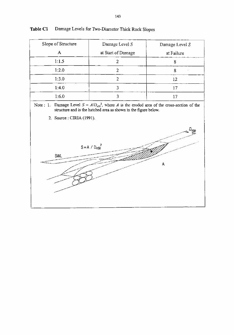
143
Table Cl Damage Levels for Two-Diameter Thick Rock Slopes
Slope of Structure
A
Damage Level
at Start of Damage
Damage Level S
at Failure
1:1.5
1:2.0
1:3.0 12
1:4.0 17
1:6.0 17
Note : 1. Damage Level S = A/Dn5Q2, where A is the eroded area of the cross-section of the
structure and is the hatched area as shown in the figure below.
2. Source : CIRIA (1991).
JnSQ

144

145
APPENDIX D
WORKED EXAMPLES

146

147
CONTENTS
PageNo.
TITLE PAGE 145
CONTENTS 147
D. 1 WAVE OVERTOPPING OF RUBBLE MOUND SEAWALL 149
D.2 WAVE OVERTOPPING OF SOLID FACE VERTICAL SEAWALL 151
D.3 REFLECTION COEFFICIENT OF RUBBLE MOUND SEAWALL 153
D.4 ROCK ARMOUR OF RUBBLE MOUND BREAKWATER 155
D.5 UNDERLAYER OF RUBBLE MOUND BREAKWATER 157
D.6 TOEPROECTION 158

148

149
D.I OF
Reference Section 5.3 and Appendix B.3.
Given
A rubble mound seawall with two layers of rock armour.
Crest level = +4.5 mPD
Slope of seawall (front face) = 1 : 2
Sea level = +3.2 mPD
Significant wave height at seawall = 2.0 m
Mean wave period = 4.4 s
Angle of incident wave to the normal of the seawall = 30 degrees
Find
Mean overtopping rate of the rubble mound seawall.
Solution
Take g = 9.81m/s2 and use Owen's formulae in Appendix B.3.1
Dimensionless crest freeboard j?*
= RJ(Tm(gHlt,r}
= (4.5-3.2)
4.4xV9.81x2.0
= 0.067
Dimensionless mean discharge Q*
= A exp (-BRJr)
From Table B3, for slope of seawall (front face) = 1:2, take empirical coefficients A and B to
be 0.00939 and 21.6 respectively.
From Table B2, for two layers of rock armour, take roughness coefficient r to be 0.5.
Q, = 0.00939 exp (-21.6x0.067/0.5)
= 5.2X10⁻⁴
Q = Q*TMgH}1/3

150
= 5.2x10^x4.4x9.81x2.0
- 0.045 m3/s per meter run of the seawall
Reduction factor for incident waves not normal to the structures Or
Or = 1-0.000152 p2
= 1-0.000152 (30)2
= 0.86
Therefore, mean overtopping discharge
= QxOr= 0.045 x 0.86
= 0.039 m3/s per meter run of the seawall
This overtopping rate is nearly equal to the suggested limit of the damage to unpaved surface,
5xlO~2 m3/m/s listed in Section 5.3.2 of this part of the Manual.

151
D.2 OF
Reference Section 5.3 and Appendix B.3.
Given
A solid face vertical seawall with toe level close to the seabed level.
Crest level = +4.5 mPD
Sea level = +3.2 mPD
Seabed level = -6.0 mPD
Significant wave height at seawall = 2.0 m
Mean wave period = 4.4 s
Incident wave angle : normal to seawall
Seabed slope = 1:30
Find
Mean rate of wave overtopping of the vertical seawall.
Solution 1Based on the method mentioned by Besley (1999) in Appendix B.3.2 :
Water depth d = 3.2 - (-6.0) = 9.2 m
Height of top of wall above still water level Rc
= 4.5 -3.2m
= 1.3m
Dimensional parameter d*
= (d/Hm)(27rd/(gTm2))
= (9.2/2.0)( 2 it 9.27(9.81 x 4.42))
= 1.4
As d. > 0.3, reflecting waves predominate, and Re/Hll3 = 1.3/2.0 = 0.65. The following
equations should apply.
Q* = 0.05 exp (-2.78 RcIHm)
where Q* is the dimensionless discharge, given by Q l(gH^~) °'5
Q* = 0.05 exp (-2.78 x 1.3 / 2.0) = 8.2 x lO'3

152
Mean overtopping discharge
= 8.2x 10^3x(9.81 x2.03f5
= 0.073 mVs per meter run of seawall
2
Based on the diagram by Goda (2000) in Appendix B.3.2 :
Equivalent deepwater wave height HQ &HV3 = 2.0 m
Significant wave period Tl/3 « 1.2 Tm = (1.2)(4.4) = 5.3 s
Wave steepness = HJI((gl2x) xTV32) « 2.0/((9.81/2/3.1459) x5.32) = 0.046
Dimensionless depth parameter d/HQ9 « d/Hl/3 = 9.2/2.0 = 4.6
Dimensionless crest parameter hJHJ « RJHl/3 = 1.3/2.0 = 0.65
By using Figure B2 (c) for the wave steepness H09/LQ = 0.036 as having the steepness nearest
to the design condition, and reading off the diagram, the dimensionless overtopping rate is
obtained as :
'32xlO
Mean overtopping rate
= 2xlO~3x(2x9.81x2.03)1/2
= 0.025 m3/s per meter run of seawall
Even though the above estimate differs from the previous estimate of Solution 1 by a factor
of 3, such diversity should be expected because the phenomenon of wave overtopping
involves a large spread of data.

153
D3 OF SEAWALL
Reference Section 5.4 and Appendix B.4.
Given
A rubble mound seawall with two layers of rock armour.
Slope of seawall = 1 : 2
Significant wave height = 2.0 m
Mean wave period = 4.4 s
Find
Reflection coefficient of the rubble mound seawall.
Solution
Assume notional permeability factor P = 0.3
Peak wave period Tp = l.lxTl/3 = l.lxl.2xrm = 1.1x1.2x4.4 = 5.8 s
(See Section 2.5.3 of Part 1 of this Manual)
Offshore wave steepness based on peak wave period sp
= 27ix2.0/(9.81x5.82)
= 0.038
Surf similarity parameter based on peak wave period %p
tana
1/2
V0.038
= 2.56
(a) Seelig and Ahrens formula
Coefficient of reflection Cr = a= 0.6x2.562/(6.6+2.562)
= 0.30
(0=0.6 and 6=6.6 as given by the formula)

154
(b) Postma formula
Coefficient of reflection Cr = 0 1 °73
= 0.14x2.56°73
= 0.28
(c) Postma formula with slope angle and wave steepness treated separately
Coefficient of reflection Cr = 0.071P -°'082 (cota)-0'62 s/°'46
= 0.071(0.3)-ao82(2)-a62(0.038)
= 0.23
(d) Postma formula modified with Allsop and Channel data
0.73Coefficient of reflection Cr = 0.125£p
- 0.125x2.56°'73
= 0.25
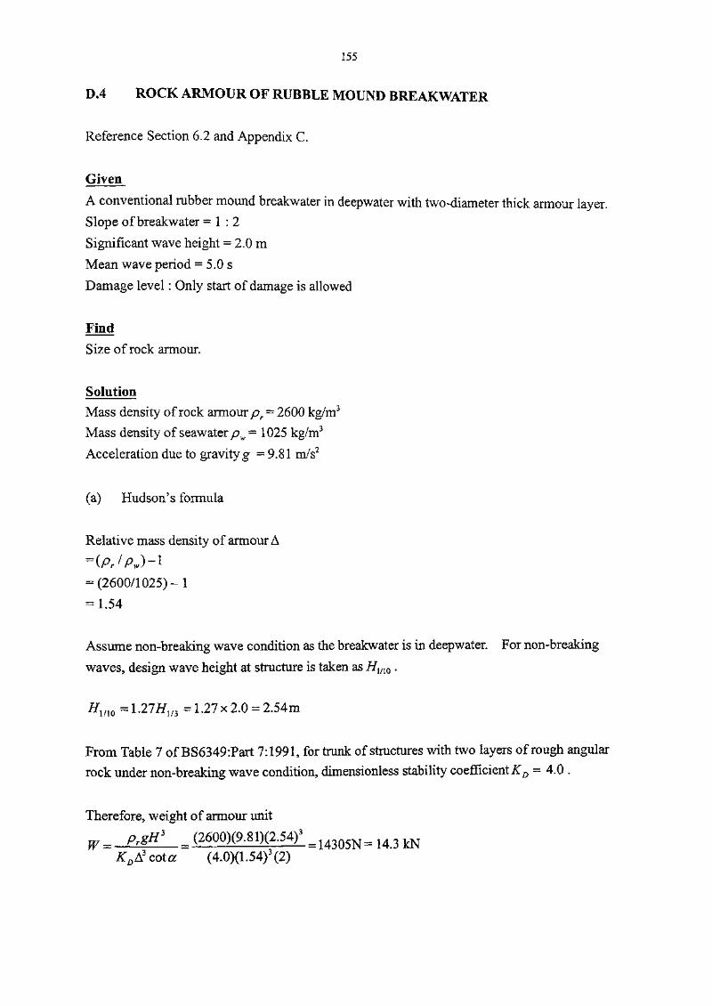
155
D*4 OF
Reference Section 6.2 and Appendix C.
Given
A conventional rubber mound breakwater in deepwater with two-diameter thick armour layer.Slope of breakwater = 1 :2
Significant wave height = 2.0 m
Mean wave period = 5.0 s
Damage level : Only start of damage is allowed
Find
Size of rock armour.
Solution
Mass density of rock armour pr= 2600 kg/m3
Mass density of seawater pw = 1025 kg/m3
Acceleration due to gravity g = 9.81 m/s2
(a) Hudson's formula
Relative mass density of armour A
= (P,//U-1
= (2600/1 025) -1
= 1.54
Assume non-breaking wave condition as the breakwater is in deepwater. For non-breaking
waves, design wave height at structure is taken as HinQ .
Hmo = \ 21 Hm = 1 .27 x 2.0 = 2.54m
From Table 7 of BS6349:Part 7:1991, for trunk of structures with two layers of rough angular
rock under non-breaking wave condition, dimensionless stability coefficient^ = 4.0 .
Therefore, weight of armour unit
(4.0)(1.54)3(2)

156
(b) Van der Meer formula
The breakwater is not in shallow water.
Take design wave height as significant wave height H]/3 = 2.0 m.
Relative mass density of armour A
Offshore wave steepness based on mean period s
gT2 9.81x5.02£> m
Surf similarity parameter for mean wave period %m
tan a 1/2
/0.051- = 2.21
Only start of damage is allowed and slope of breakwater = 1 : 2 .
Therefore, from Table Cl, damage level S = 2.
Assume number of waves N= 4000 and notional permeability factor P = 0.3.
Critical value of
p+a5) =[(6.2)(0.3)a31V05]1/(a3+0-5) =3.98
Since %m<%c, the formula for plunging waves should be used.
#,M/3
AA.50-f." \0.2
Thus, nominal rock diameter DH
0.2 2.0V2.21
1.54(6.2)(0.3)ai8(-^=)
4000'0.2 = 0.77 m
Nominal mass of rock armour = (0.77)3(2600) = 1187 kg
Weight of rock armour = 11.6 kN

157
D.5 OF
Reference Section 6.2.4.
Given
A conventional rubber mound breakwater with two-diameter thick armour layer.Nominal mass of rock armour = 2000 kg
D}5 of rock armour = 0.83 m
Find
Size of underlayer rock.
Solution
Take the number of rock layers of the underlayer n = 2For rock, layer thickness coefficient £A = 1.15
Mass density of rock = 2600 kg/m3
The nominal mass of rock in the underlayer should be at least 1/10 of the nominal mass of
rock armour, i.e. > 2000/10 = 200 kg.
The nominal rock size of the underlayer D50 > (200/2600)173 = 0.425 m
To prevent smaller rocks in the underlayer from being taken out through the armour layer by
wave action, the following filter criteria are checked.
-^85(underlayer) —
rmour) / -^15(underlayer) - 20
= 0.83m
Therefore, A5(undenayer) ^ 0-21 m0.04 m < D15(under,ayer) ^ 0.21 HI
Note :The filter requirement of the underlayer should also be checked with the size of core material
of the breakwater, although this is not shown in this worked example.

158
D.6 TOE
Reference Section 6.2.8 and Figure 16.
Given
A critical vertical seawall located in an open exposed area.
Sea level = +3. 2 mPD
Seabed level = -5.0 mPD
Top level of toe protection = -4.0 mPD
Slope of rubble toe protection = 1 : 2
Significant wave height at seawall = 2.0 m
Mean wave period = 4.4 s
Find
Rock size and width of toe protection.
Solution
Referring to Figure 1 6,
</, = 3.2 - (-4.0) = 7.2 m
ds= 3.2 -(-5.0) = 8.2m
For intermediate water depth (i.e. — < — <—), the wavelength associated with depth d{ is:.Z j JL> jL
In L
9.81x4.4'tanh
2;r L
By iteration, L = 27.9 m
L 27.9
Therefore, the assumption of intermediate water depth is justified.
As the seawall is situated at open exposed site, the design wave height H is taken to be H1/m
according to Figure 16.
H= 1.67 Hl/3 = 1.67 x 2.0 = 3.3 m
159
The width of toe protection is given by the following:B>OAd = 0.4 x 8.2 = 3.3m
:2x3.3 = 6.6 m
For B = 6.6 m
L 27.9
T,~Hi~
~H~^3~
From Figure 16, Ns = 3.8
The mass of rock required for toe protection is:
prH* . (2600)(3.3)3
Ns3(sr-l)
3 (3.8)3(2600/1025-I)3 =469kg
The width of toe protection is checked with the following:
B > 4 times size of rock = 4 x (469 / 2600)1'3 - 2.3 m
This requirement is also satisfied. Therefore, width of toe protection = 6.6m.

160

161
GLOSSARY OF TERMS AND SYMBOLS

162

163
OF
Armour layer. The outermost protective layer of a nibble mound structure composed of
armour units which are either quarry rock or specially shaped concrete units.
Bermstones. The protective layer laid in front of the toe of the structure to prevent
scouring of foundation material due to waves and currents.
Surf similarity parameter. Being defined as the ratio of tangent of slope angle to the square
root of wave steepness, it has often been used to describe the form of wave breaking
and to predict wave runup on a sloping beach or structure.
Breakwater head. The end of a breakwater which is more vulnerable to wave attack at all
directions. The design of which requires special attention and a more robust
structure is required.
Breakwater trunk. The body of the breakwater other than the structure head.
Coping. The uppermost in situ concrete portion of a vertical seawall It is constructed in
the late stage of the construction programme for minimizing the effects of wall
settlement upon completion.
Core. The innermost material of a rubble mound breakwater, the permeability of which
determines the extent of wave transmission to the leeward side of the breakwater
due to long period wave. The more porous is the core material, the higher will be
the degree of wave transmission.
Filter. Intermediate layer to prevent fine materials of an underlayer from being washed
through the voids of an upper layer.
Freeboard. The height of a structure above still water level
Longshore sediment transport. The sediment that is transported in the alongshore direction
in the nearshore zone by waves and currents.
Overtopping. Water passing over the top of the seawall
Plunging waves. A kind of breaking waves which occur on mildly to steeply sloping

164
beaches or structures and are characterized by the crest of the wave curling over
forward and impinging onto part of the wave trough. The wave Itself is
spectacular when air escapes by bursting through the back of the wave or by
blowing out at a nonbreaking section of wave crest.
Still water level. Water level which would exist In the absence of waves.
Surging waves. A kind of breaking waves which occur on very steeply sloping beaches or
structures and are characterized by narrow or nonexistent surf zones and high
reflection.
Run-up. The rush of water up a structure as a result of wave action.
Toe of structure. The base of the structure on its seaward face.
Underlayer. A granular layer between the armour layer and the core material, and
functions as separation and filter. It also provides a foundation for placement of
armour layer.
Volumetric porosity. The ratio of void volume to total volume.
Wave steepness. A ratio of the wave height to the wavelength. The limiting wave
steepness in deep water is about 0.142 which occurs when the water particle
velocity at the wave crest just equals the wave celerity. A further increase in
steepness would result in particle velocities at the wave crest greater than the wavecelerity and breaking starts to occur.
Wave wall. A structure built on the seawall or breakwater to reduce wave overtopping.

165
OF
A Erosion area In a cross-section
B Crest width
Cr Wave reflection coefficient
Ct Wave transmission coefficient
D Nominal size of an equivalent cube
D15 15% of the material passing through that size
D50 50% of the material passing through that size
DS5 85% of the material passing through that size
d Water depth
Et Incident wave energy
Er Reflected wave energy
Et Transmitted wave energy
g Acceleration due to gravity
H Wave height
Hl/3 Significant wave height, also denoted as Hs in other literatures
HI Incident wave height
Hmax Maximum wave height
H0' Equivalent deepwater significant wave height
Hr Reflected wave height
Htotal Total wave height
KD Dimensionless stability coefficient in Hudson's formula
£A Layer thickness coefficient
L Wavelength
L0 Deepwater wavelength
N Number of waves
Na Average number of armour units per unit area

166
N0 Number of waves during a peak of storm events
n Number of armour layers or number of rock layers
P Notional permeability factor
p Volumetric porosity
Q Mean overtopping discharge rate per meter run of structure
Rc Freeboard between still water level and crest of structure
Ru2% The run-up level exceeded by 2% of the incident waves
Rui The run-up at / % exceedance level.
r Roughness coefficient
S Damaged level
s Slope of seabed
sm Offshore wave steepness based on mean wave period
sp Offshore wave steepness based on peak wave period
T Wave period
Tm Significant wave period, also denoted as Ts in other literatures
Tm Mean wave period
ta Thickness of armour layer
tu Thickness of underlayer
Wa Weight of an armour unit
W Weight of a rock in the underlayer
a Slope angle of structure
ft Incident wave angle relative to normal of structure
7a Unit weight of armour unit
7r Unit weight of rock
7w Unit weight of water
K Critical surf similarity parameter for transition from plunging to surgingc waves
%m Surf similarity parameter based on mean wave period

2 i iOV 213167
%p Surf similarity parameter based on peak wave period
p, pw Mass density of seawater
pr Mass density of rock
Relative mass densitye.g. for rock A= (mass density of rock/mass density of water) - 1

X18300220
HK 627.58 P83Port works design manual. Part4, Guide to design of seawallsand breakwatersHong Kong : Civil Engineering
Date Due


![OUG - Hitachi ElevatorEN HKG COP HKG COPSS550 SS550MS EN MS EN/HKG COP/SS550/MS Load [kg] Speed [m/min] Minimum pit depth : P [mm] Maximum pit depth : P [mm] Counterweight location](https://static.documents.pub/doc/80x56/60ba10ba8d93e149dc71e79d/oug-hitachi-en-hkg-cop-hkg-copss550-ss550ms-en-ms-enhkg-copss550ms-load-kg.jpg)


