CEPT REPORT 19 21 December 2007 Editorial revision 30 October 2008 CEPT Report 19 Report from CEPT to the European Commission in response to the Mandate to develop least restrictive technical conditions for frequency bands addressed in the context of WAPECS Final Report on 21 December 2007 with editorial revisions on 17 March 2008 and 30 October 2008 by the ECC Electronic Communications Committee CEPT Electronic Communications Committee (ECC) within the European Conference of Postal and Telecommunications Administrations (CEPT)
Transcript
CEPT REPORT 19 21 December 2007
Editorial revision 30 October 2008
CEPT Report 19
Report from CEPT to the European Commission in response to the Mandate to develop least restrictive technical
conditions for frequency bands addressed in the context of WAPECS
Final Report on 21 December 2007 with editorial revisions on 17 March 2008
and 30 October 2008 by the
ECCElectronic Communications Committee
CE
PT
Electronic Communications Committee (ECC) within the European Conference of Postal and Telecommunications Administrations (CEPT)
CEPT REPORT 19 Page 2
CEPT Report 19 History
Revision Note – Dresden – 17 March 2008 Editorial revision resulting from some comments received during public consultation Revision Note – Cordoba – 30 October 2008 Other comments received during public consultation were related to the absence of studies on the impact of terminal-to-terminal interference. This led to the development of complementary studies addressed in the ECC Report 131 [55]. The editorial revision provides cross-references between the ECC Report 131 [55] and this report.
CEPT REPORT 19 Page 3
Response to the EC Mandate on WAPECS
List of Abbreviations .........................................................................................................5 1. Executive Summary........................................................................................7 2. Introduction......................................................................................................9 3. General considerations.................................................................................10 3.1. Background.........................................................................................................10 3.2. Technical and economic considerations related to flexibility.....................12 3.3. EU Regulatory regime considerations related to flexibility ........................15 4. General methodology for technical analysis ............................................16 4.1. Boundary conditions .........................................................................................16 4.2. Proposed basic radio network scenarios for WAPECS.................................16
4.2.1. Communication link including a fixed TS or receiver .........................16 4.2.2. Communication link including a mobile TS at an unknown location17
4.3. Reference WAPECS systems............................................................................17 4.4. Models for defining Least Restrictive Technical Conditions .......................18
4.4.1. Model 1: Traditional compatibility and sharing analysis method....19 4.4.2. Model 2: The Block Edge Mask (BEM) approach to define spectrum usage rights (SURs) ...................................................................................................19 4.4.3. Model 3: PFD MASKS - Aggregate PFD approach ...............................23 4.4.4. Model 4: Aggregate PSD Transmitter Masks .......................................25 4.4.5. Model 5: The Hybrid Approach ...............................................................25 4.4.6. Model 6: Space-Centric Management ...................................................26 4.4.7. Description of the characteristics of each of the models studied: ...29
4.5. Interference analysis scenarios ......................................................................30 4.5.1. WAPECS vs in-band non-WAPECS (Case A or D)................................30 4.5.2. WAPECS vs out of band non-WAPECS (Case B)..................................31 4.5.3. WAPECS vs out of block WAPECS but in-band (Case C) ...................31 4.5.4. WAPECS vs WAPECS in geographically separated areas (Case E) ..31
5. Band by band analysis .................................................................................32 5.1. Introduction........................................................................................................32 5.2. General principles applicable to all bands.....................................................32 5.3. Analysis for the 3.4-3.8 GHz band .................................................................34
5.3.1. Stage 1: Assumptions for WAPECS in this band .................................34 5.3.2. Stage 2: WAPECS vs in-band non-WAPECS.........................................34 5.3.3. Stage 3: WAPECS vs out of band non-WAPECS..................................35 5.3.4. Stage 4: WAPECS vs out of block WAPECS but in-band ...................35 5.3.5. Stage 5: WAPECS vs co-frequency WAPECS in a geographically adjacent area ..............................................................................................................35 5.3.6. Stage 6: Results for the 3.4-3.8 GHz band .........................................35
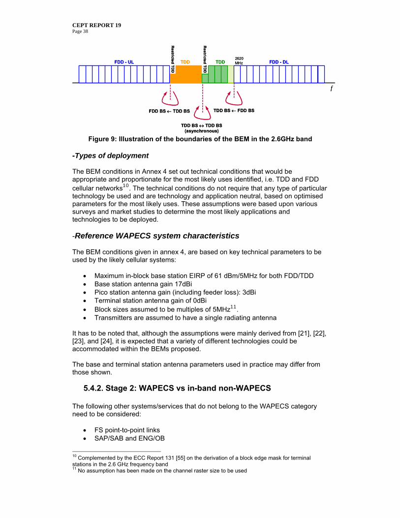
5.4. Analysis for the 2500-2690 MHz band ..........................................................37 5.4.1. Stage 1: Assumptions for WAPECS in this band .................................37 5.4.2. Stage 2: WAPECS vs in-band non-WAPECS.........................................38 5.4.3. Stage 3: WAPECS vs out of band non-WAPECS..................................39 5.4.4. Stage 4: WAPECS vs out of block WAPECS but in-band ...................40 5.4.5. Stage 5: WAPECS vs co-frequency WAPECS in a geographically adjacent area ..............................................................................................................41 5.4.6. Stage 6: Results for the 2500-2690 MHz band...................................41
5.5. Analysis for the 880-915 MHz / 925-960 MHz bands .................................42 5.5.1. Stage 1: Assumptions for WAPECS in this band .................................42 5.5.2. Stage 2: WAPECS vs in-band non-WAPECS.........................................44 5.5.3. Stage 3: WAPECS vs out of band non-WAPECS..................................44 5.5.4. Stage 4: WAPECS vs out of block WAPECS but in-band ...................44 5.5.5. Stage 5: WAPECS vs co-frequency WAPECS in a geographically adjacent area ..............................................................................................................45 5.5.6. Stage 6: Results for the 880-915 MHz / 925-960 MHz bands .........45
CEPT REPORT 19 Page 4
5.6. Analysis for the 1710-1785 MHz / 1805-1880 MHz bands ........................46 5.6.1. Stage 1: Assumptions for WAPECS in this band .................................46 5.6.2. Stage 2: WAPECS vs in-band non-WAPECS.........................................47 5.6.3. Stage 3: WAPECS vs out of band non-WAPECS..................................47 5.6.4. Stage 4: WAPECS vs out of block WAPECS but in-band ...................48 5.6.5. Stage 5: WAPECS vs co-frequency WAPECS in a geographically adjacent area ..............................................................................................................48 5.6.6. Stage 6: Results for the 1710-1785 MHz / 1805-1880 MHz bands 48
5.7. Analysis for the 1900-1980 MHz / 2010-2025 MHz / 2110-2170 MHz bands 49
5.7.1. Stage 1: Assumptions for WAPECS in this band .................................49 5.7.2. Stage 2: WAPECS vs in-band non-WAPECS.........................................49 5.7.3. Stage 3: WAPECS vs out of band non-WAPECS..................................50 5.7.4. Stage 4: WAPECS vs out of block WAPECS but in-band ...................50 5.7.5. Stage 5: WAPECS vs co-frequency WAPECS in a geographically adjacent area ..............................................................................................................51 5.7.6. Stage 6: Results for the 1900-1980 MHz / 2010-2025 MHz / 2110-2170 MHz bands .........................................................................................................52
5.8. Analysis for the 470-862 MHz band...............................................................53 5.8.1. Stage 1: Assumptions for WAPECS in this band .................................54 5.8.2. Stage 2: WAPECS vs. in-band non-WAPECS .......................................56 5.8.3. Stage 3: WAPECS vs out of band non-WAPECS..................................56 5.8.4. Stage 4: WAPECS vs. out of block WAPECS but in-band ..................56 5.8.5. Stage 5: WAPECS vs. co-frequency WAPECS in geographically different areas.............................................................................................................57 5.8.6. Stage 6: Results for the 470-862 MHz band ......................................58
6. Conclusions ....................................................................................................60 Annex I: In-block and out-of-block limits defined for BWA around 3.5 GHz......63 Annex II: Illustration of BEM flexibility applied to BWA systems around 3.5 GHz
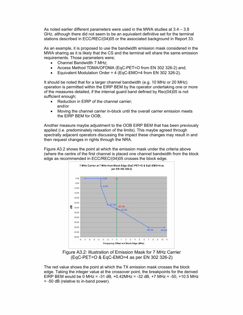
65 Annex III: .. EIRP BEM for Central and Terminal Stations in the 3.4-3.8 GHz band
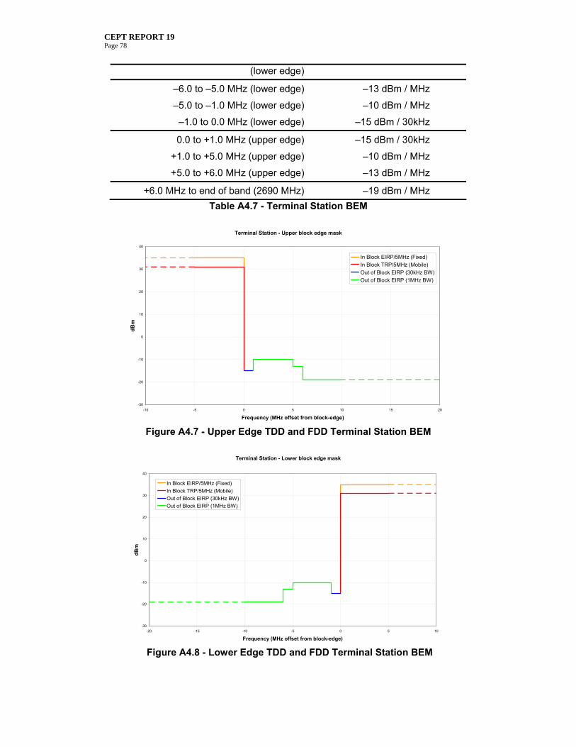
68 Annex IV:Block Edge Masks for the 2.6GHz band ....................................................70 A4.1 Introduction ...........................................................................................................70 A4.2 Parameters to be used for developing and agreeing the levels in the 2.6 GHz BEM. .........................................................................................................................70 A4.3 Unwanted Out of Band (OOB) emissions outside the band 2500-2690 MHz...........................................................................................................................................71 A4.4 BEM for BS .............................................................................................................71 A4.4.1 Baseline requirement for the 2500-2690 MHz band ...................................72 A4.4.2 BEM for unrestricted frequency blocks..........................................................73 A4.4.3 BEM for restricted frequency blocks. .............................................................75 A4.4.4 Examples of BEMs .............................................................................................76 A4.5 TDD or FDD Mobile/Terminal Stations ..............................................................77 A4.5.1 TS Maximum In-band power.......................................................................77 A4.5.2 TS Block Edge Mask (BEM)..........................................................................77 Annex V:GSM Frequency utilisation.............................................................................79 Annex VI:Industry point of view ..................................................................................81 Annex VII:References ....................................................................................................91
CEPT REPORT 19 Page 5
LIST OF ABBREVIATIONS
Abbreviation Explanation 3GPP 3rd Generation Partnership Project ACIR Adjacent Channel Interference Ratio ACLR Adjacent Channel Leakage Ratio ACS Adjacent Channel Selectivity ARNS Aeronautical Radio Navigation Service ATPC Automatic Transmit Power Control BEM Block Edge Mask BRAN Broadband Radio Access Network BS Base station BWA Broadband Wireless Access CDMA Code Division Multiple Access CEPT European Conference of Postal and Telecommunications CS Central Station DECT Digital Enhanced Cordless Telecommunications DL Down Link DME Distance Measuring Equipment DVB-H Digital Video Broadcasting – Handheld DVB-T Digital Video Broadcasting Terrestre e.i.r.p. Equivalent isotropically radiated power EC European Commission ECA European Common Allocation Table ECC Electronic Communications Committee ECS Electronic Communications Service EESS Earth Exploration Satellite Service EGSM Extended GSM ENG/OB Electronic News Gathering / Outside broadcasts ERO European Radiocommunication Office ETSI European Telecommunications Standards Institute EU European Union FDD Frequency Division Duplex FM Frequency Modulation FS Fixed Service FSS Fixed Satellite Service FWA Fixed Wireless Access FWS Fixed Wireless Systems GSM Global System for Mobile communication GSM-R GSM ‘Railways’ HEN Harmonised Standard IEEE Institute of Electrical and Electronics Engineers IMT/IMT-2000 International Mobile Telecommunications/International Mobile
Telecommunications-2000 ITU International Telecommunication Union JTIDS Joint Tactical Information and Distribution System LBT Listen Before Talk LOS Line Of Sight LTE Long Term Evolution METSAT Meteorological Satellite
CEPT REPORT 19 Page 6
MIDS Multifunctional Information Distribution System MIMO Multiple Inputs Multiple Outputs ML Mobile Station MMDS Microwave Multipoint Distribution System MoU Memorandum of Understanding MS Mobile Service MSS Mobile Satellite Service MWA Mobile Wireless Access NLOS Non Light Of Sight NRA National Regulatory Authority NWA Nomadic Wireless Access OFDM Orthogonal Frequency Division Multiplexing OOB Out Of Band PAMR Public Access Mobile Radio PFD Power Flux Density P-MP Point-MultiPoint PMR Professional (Private) Mobile Radio P-P Point to Point PSD Power Spectral Density RAS Radio Astronomy Service RPC Reference Planning Configurations RR Radio Regulations RRC Regional Radiocommunication Conference RS Repeater Station RSPG Radio Spectrum Policy Group R&TTE Radio and Telecommunications Terminal Equipment SAP/SAB Services Ancillary to Programming / Services Ancillary to Broadcasting SRS Space Research Service SSR Secondary Surveillance Radar SUR Spectrum Usage Rights TACAN Tactical Air Navigation TDD Time Division Duplex TETRA TErrestrial Trunked RAdio TFTS Terrestrial Flight Telephone System TS Terminal Station UHF Ultra High Frequency UL Up Link UMTS Universal Mobile Telecommunications System WAPECS Wireless Access Policy for Electronic Communications Services WRC World Radiocommunication Conference
CEPT REPORT 19 Page 7
1. Executive Summary This report provides the response to the EC mandate to CEPT “To develop least restrictive technical conditions for frequency bands addressed in the context of WAPECS” [1]. The Mandate addressed the following frequency bands:
With respect to the frequency bands listed above, the Mandate requests four areas of investigation which have been completed as follows: 1. Review existing technical conditions attached to the rights of use of these frequency bands taking into account the results of the questionnaire to administrations expected by 1 September 2006 and which will be provided to CEPT upon availability; This task was completed and the results were submitted to the EC in the interim response to the mandate, which was delivered according to the schedule. 2. to the extent possible, to identify future common and minimal (i.e. least restrictive) technical conditions across frequency bands listed above, in the spirit of Article 1 of the Authorisation Directive, to become ultimately applicable throughout the Community and to justify any deviations from the long term policy goals contained in the RSPG opinion on WAPECS; This final CEPT Report focuses on this part of the mandate. Due to the complexity of the given task; the investigation has been conducted in two parallel work streams: 1) A study to determine some general methodologies for deriving least restrictive technical conditions, with examples of how the Block Edge Mask (BEM) methodology can be used on its own or as a basis to derive examples of least restrictive technical conditions using other more innovative methodologies; and 2) A band by band analysis which applies one of the methodologies (BEM) to give agreed technical parameters or examples for each WAPECS band. Establishing possible technical conditions for introducing WAPECS in subject bands requires producing different sets of assumptions and co-existence studies, tailored to the specific situation in each of the WAPECS band. CEPT has chosen to follow a step-by-step strategy and accordingly decided to address the subject bands with the following priority: The 3.4-3.8 GHz band and the 2.5-2.69 GHz band have been given the highest
priority; The 900 MHz; 1800 MHz and 2 GHz bands have been treated with lower priority; Regarding the band 470-862 MHz, it seemed logical to postpone studies related
to this mandate for this band pending finalisation of “Digital dividend” studies (subject of a separate EC Mandate).
CEPT REPORT 19 Page 8
Based on the analysis presented in this Report, the BEM approach has been chosen for the description of technical conditions in response to task 2 of the Mandate, noting that it is the most developed concept for the time being. Other models are presented in the report and may become relevant in the future for other bands. CEPT believes that all the frequency bands addressed in this response to the Mandate should be suitable from a technical perspective for the introduction of flexibility. Taking into account the prioritisation described above and the status of studies, CEPT proposals concerning the various bands are the following: 1. A BEM approach is proposed in the 3.4-3.8 GHz, and the relevant technical
conditions are described in section 5.3 and Annex 1 of this report with supplementary information in Annexes 2 and 3 ;
2. Concerning the 2.5-2.69 GHz band, the technical conditions are contained in section 5.4 and Annex 41;
3. Detailed investigation of WAPECS in the remaining bands addressed by this Mandate will need further consideration. Any real-life experience that could be gathered from the introduction of WAPECS in the two bands mentioned above may be beneficial for this further work.
CEPT is willing to continue studying the issue of introduction of WAPECS in the future, e.g. with reference to a possible follow-up mandate from the EC.
The technical parameters shall be applied as an essential component of conditions necessary to ensure co-existence in the absence of bilateral or multilateral agreements2 between operators of networks in adjacent blocks and areas (i.e. frequency and geography), without precluding less stringent technical parameters if agreed among the operators of such networks In the process of introducing WAPECS, circumstances will evolve and the conclusions and recommendations in this report need to be kept under review. 3. noting that results are urgently needed for the 2nd generation mobile bands, study and confirm the technical feasibility and support for operating technologies other than GSM in the bands currently used for 2nd generation mobile services and develop a channelling arrangement including all technical elements needed in order to facilitate a common approach within the Community This task was completed and the results were submitted to the EC in the interim response to the mandate, which was delivered according to the schedule. 4. if time and resources allow, look at the band 1800-1805 MHz (upper TFTS band) in the context of this Mandate. It has not been possible to investigate this band in the time available.
1 Complemented by the ECC Report 131 [55] on the derivation of a block edge mask for terminal stations in the 2.6 GHz frequency band 2 It is recognised that there will be cases where co-operation will still be needed.
CEPT REPORT 19 Page 9
Other activities on the flexible use of the spectrum outside of the scope of the EC mandate to CEPT are ongoing. The frequency bands identified for study were 862-870 MHz, 1785-1805 MHz and 57-59 GHz, with the aim of testing the principle of flexible use of spectrum.
2. Introduction In relation to the work conducted in response to the Mandate, it is important to recall the considerations that led to the development of WAPECS and the preliminary technical discussions on these issues. The Lisbon agenda of the EC has been developed with the objective to create economic growth in the European Union. A means to achieve this objective is to make Europe the number one in Information and Communication Technology in the world. Some studies [1] suggest that this objective requires the introduction of more flexible and more liberal regulatory rules, for instance in the field of spectrum management. A report commissioned by the European Commission [2] shows the extent of the potential gains if greater flexibility was introduced into the way spectrum is allocated and utilised. It also shows that there is a powerful synergy between secondary spectrum trading and spectrum liberalisation. WAPECS is one approach that the EC has mandated CEPT to explore in order to have the possibility of realising these gains. The pros and cons of such changes to spectrum management including its economical implications have also been studied in the ECC Report 80 [3]. To achieve the required level of flexibility by WAPECS, one central topic of the whole discussion is the need for an investigation of the technical and operational conditions required to avoid harmful interference in the frequency bands identified. This topic is covered by the EC mandate to CEPT [1]. The intention is to ensure that the technical requirements identified as far as possible are independent of the identification of one or more particular technologies and of the service to be provided. This response of CEPT to the EC-mandate describes basic technical approaches, how technical aspects of spectrum usage rights can be described in a way, that usage of spectrum is as little as possible restricted by technology-specific requirements. It aims at definition of spectrum usage rights that contain least restrictive technical conditions. However, it should be noted that the technical conditions are not completely independent of other aspects of the rights of use. Notably regulatory provisions, for example, allowing some kind of light licensing, may, in some cases, facilitate a better usage of the spectrum and ensure a flexibility and efficiency. (e.g. 3,4-3,8 GHz band). The conclusions and recommendations of this report should not be regarded as immutable but as one stage, although an important one, in the process of introducing WAPECS. In other words, circumstances are continuing to evolve and the recommendations in this report need to be kept under review.
CEPT REPORT 19 Page 10
3. General considerations
3.1. Background Protection of radio communication services is a key cornerstone for spectrum management with the appropriate definition of protection/sharing criteria. A focal point in this discussion is the concept of neutrality, it is essential to consider the definition of both service and technology neutrality. Service neutrality under the WAPECS concept (Figure 1) is understood as: “Any electronic communications service (ECS) may be provided in any WAPECS band over any type of electronic communications network. No frequency band should be reserved for the exclusive use of a particular ECS. This is without prejudice to any obligation to provide some specific service in a specific band or sub-band, e.g. broadcasting and emergency services.” It is important to highlight that this definition is not relying on the “neutrality” taking as a basis the Radio Service definition (as in Radio Regulations); it specifically makes its linkage with ECS, as defined in the Framework Directive 2002/21/EC [4]3. This is further explained in the RSPG opinion [5] by stating that different networks can provide mobile, portable, or fixed access, for a range of electronic communications services, using the term “electronic communications services” in the sense of the Framework Directive 2002/21 (e.g., IP access, multimedia, multicasting, interactive broadcasting, data casting), under one or more frequency allocations (mobile, broadcasting, fixed), deployed via terrestrial and/or satellite platforms using a variety of technologies to seamlessly deliver these services to users. On the other hand, technological neutrality is referred [5] as “For each WAPECS frequency band, provided that the associated electronic communications network complies with the relevant spectrum technical requirements, technological neutrality and flexibility in future use of the spectrum should be ensured. For justified reasons, in line with recital 184 of the Framework Directive, certain technological requirements may be imposed by Member States or at the EU level.” The application of “neutrality” relies on the definition of a minimum set of parameters to which a certain radio system must adhere. Moreover, from a spectrum engineering point of view, the implementation of a radio system in a specific frequency band requires the consideration of many parameters (e.g., transmitter and receiver
3 Article 2(c) (Framework Directive 2002/21/EC): “electronic communications service means a service normally provided for remuneration which consists wholly or mainly in the conveyance of signals on electronic communications networks, including telecommunications services and transmission services in networks used for broadcasting, but exclude services providing, or exercising editorial control over, content transmitted using electronic communications networks and services…” 4 Recital 18 (Framework Directive 2002/21/EC): “The requirement for Member States to ensure that national regulatory authorities take the utmost account of the desirability of making regulation technologically neutral, that is to say that it neither imposes nor discriminates in favour of the use of a particular type of technology, does not preclude the taking of proportionate steps to promote certain specific services where this is justified, for example digital television as a means for increasing spectrum efficiency.”
CEPT REPORT 19 Page 11
specific, or access methods TDD, FDD), which goes far beyond the general approach of having a simple analysis (e.g., just based on spectrum mask).
Figure 1: WAPECS concept as illustrated in [5]
Compatibility studies carried out with specific technology / applications are enabling a fine tuning of parameters ensuring the best spectrum efficiency. The wider the assumptions are in relation to interfering and interfered systems (bandwidth, power, antenna category, TDD/FDD, deployment …), the more it is necessary to consider worst case scenarios. For example, a lack of proper consideration on duplex arrangements may lead to the establishment of unnecessary guard bands, therefore directly affecting the spectrum efficiency. This could also lead to the following consequences: Constraining severely some of the parameters (power, antenna height, spectrum
mask …), thus preventing some of the possible applications or technologies; Not defining coexistence rules, thus accepting that, depending on the
development of technology/applications, interference situation may develop in this frequency band.
Therefore, there is always a balance between the level of neutrality and the technical spectrum efficiency, which is one of the objectives in the EC Radio Spectrum Decision [6]. Nevertheless, different degree of requirements for these compatibility studies may be envisaged, allowing for a certain level of flexibility to be taken when establishing the minimum required set of technical conditions to be applied for coexistence. Therefore, technical spectrum efficiency is not an absolute notion. It has to be seen in the context of the allowed “neutrality”, i.e., different conditions associated with the assumption scenarios leads to different technical spectrum efficiency.
CEPT REPORT 19 Page 12
3.2. Technical and economic considerations related to flexibility
Historically, identification of a particular technology and/or service enabled regulators to plan and manage the spectrum with a high degree of certainty about the nature of the radio transmissions in a given frequency band. This enabled regulators to achieve a high degree of technical efficiency since the characteristics of the services sharing a frequency band would be known or specified to high degree of certainty when planning spectrum allocations. However, some European Administrations / regulators now believe that for several reasons, this model of spectrum management has come under increasing strain. They believe that due to the rate of innovation and growth in demand for spectrum (especially between about 400 MHz and 4 GHz), a new model is desired that inspires more confidence than a model based on regulatory decisions for the appropriate services that should be provided and the technologies to be employed. They also believe that the existing methods of band planning that may maximise technical efficiency might not maximise the economic benefits that can be achieved in terms of benefits for citizens and consumers. Some of these new approaches to defining application and technology neutral spectrum usage rights are now under consideration by these European administrations. Therefore it is important that whatever decisions are taken at a European level as a result of this Mandate do not prevent those member states from continuing to develop and pioneer new approaches to defining spectrum usage rights. Achieving spectrum usage rights that contain least restrictive technical conditions is not straightforward. Generally speaking, technical efficiency is maximised when spectrum use is homogeneous (or, at least, the nature of the sharing services, as well as their characteristics of deployment are known and do not change). If users have more flexibility, it is necessary to allow for a wider variety of technologies and applications in a band and to derive conditions that allow them to co-exist without harmful interference. It should be noted that although such a general approach will allow for the less homogeneous use of the spectrum, it may lead to more stringent requirements for equipment which in turn may have implications for equipment costs and/or geographical/frequency separations. In order to secure the full benefits of the new approach, it is therefore necessary to have a mechanism in place that allows users to negotiate between themselves to adjust the boundaries of their spectrum usage rights. These negotiations might need to be sanctioned by the regulator in some way. A full discussion of the details of how to achieve this is beyond the scope of this Mandate but it is relevant to note the linkage, because it illustrates that technical and regulatory issues cannot be considered in isolation from each other but may be complementary. For instance, spectrum usage rights may fix minimal technical conditions but can give opportunities for users to relax these limits based on a mutual agreement. Developments in spectrum regulatory policy can be expected to influence how spectrum usage rights should be defined so as to maximise flexibility and vice versa. For example, as approaches to spectrum management and the extent to which secondary spectrum trading is allowed in member states is shifting, the optimal approach to defining least restrictive technical conditions will also change. This interaction is illustrated in more detail in the Figure 2 below.
CEPT REPORT 19 Page 13
The considerations that would need to be taken into account when looking to provide flexibility in individually licensed bands and bands covered by either licence exemption or light licensing regimes would differ. However, the basic process that leads to deciding a minimum set of conditions for all bands irrespective of the licence conditions can be the same and is shown below. The flexibility of the spectrum allocation is determined by the final minimum technical conditions and how they are reflected either in the individual licence conditions or exemption regulations. There are many different ways in which technical restrictions on spectrum use can be formulated and presented and the way in which this is done can have profound effects on the flexibility that exists for spectrum users, and on the incentives for efficient use of the spectrum. At the most general level, there is a trade-off between increasing the flexibility available to any one user of the spectrum and reducing the risk of interference to other users. However, this trade-off can be managed more or less effectively depending on the way in which the technical constraints are specified in the usage rights of the licensee, and the way in which change to any given set of constraints is managed. Economic efficiency requires spectrum to be used in the way that delivers highest value to society. In a fast changing environment where new technologies continue to develop and evolve, the most beneficial use may well not be the same as that which has been decided by the regulator as any regulator may have limited and incomplete information on which to base a decision. Moreover, change from one use, decided and planned by the regulator, to another use, decided and planned in the same way, is a time-consuming process. The problem of inflexibility may result in poor economic efficiency of spectrum use. They have been made more pressing in those cases where innovation in existing, as well as new, wireless technologies means a higher demand for access to spectrum. In these cases, through the introduction of new, and the evolution of existing technologies, it is expected that more economically efficient spectrum usage will result without increasing the probability of unacceptable interference between users or radio services. It is therefore desirable that regulatory decisions that are taken impose the minimum necessary constraints. This is not simply a matter of technical analysis but needs also to take into consideration the existence of possible market failures. In particular for manufacturers and operators to be given sufficient incentive to plan investment in new products due care must also be taken by administration/regulators to provide enough contiguous spectrum with suitable arrangements to cater for the current trend in mobile communication systems towards higher bandwidth (e.g. 20MHz) services where information based traffic is more prevalent. In addition for operators and manufacturers to take advantage of the benefits provided through economies of scale sufficient spectrum would have to be released on a regional basis (i.e. CEPT/EU member states) in a timely manner. In some countries the process shown below has been adopted in order to try to alleviate some of the economic risks when specifying minimal technical conditions to be placed on spectrum allocations whilst still taking into account the costs of harmful interference to services.
CEPT REPORT 19 Page 14
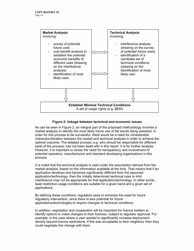
Figure 2: linkage between technical and economic issues
As can be seen in Figure 2, an integral part of the proposed methodology involves a market analysis to identify the most likely future use of the bands being awarded. In order for this process to be successful, there would be a need for considerable interaction/iteration between the market and technical analysis in order to achieve the optimal outcome. The detailed process, e.g. who should be responsible for different parts of the process, has not been dealt with in this report. It is for further analysis. However, it is important to stress the need for transparency and involvement of potential operators, manufacturers and standard developing organisations in this process. It is noted that the technical analysis is valid under the assumption derived from the market analysis, based on the information available at the time. That means that if an application develops and becomes significantly different from the assumed application/technology, then the initially determined technical rules to limit interference may not be appropriate for that application/technology. In other words, least restrictive usage conditions are suitable for a given band and a given set of applications. By defining these conditions, regulators seek to minimise the need for future regulatory intervention, since there is less potential for future applications/technologies to require changes to technical conditions. In addition, negotiation and cooperation will be important for licence holders to identify options to make changes to their licences, subject to regulator approval. For example, in the case where a user wanted to significantly increase deployment density beyond licence restrictions, if this was acceptable to their neighbour then they could negotiate this change with them.
Technical Analysis Involving:
- interference analysis (drawing on the survey of potential future uses)
- identification of a candidate set of technical conditions (drawing on the identification of most likely use)
Market Analysis Involving:
- survey of potential future uses
- cost benefit analysis to establish the potential economic benefits of different uses (drawing on the interference analysis)
- identification of most likely uses
Establish Minimal Technical Conditions A set of usage rights (e.g. BEM)
CEPT REPORT 19 Page 15
3.3. EU Regulatory regime considerations related to flexibility
Licensing of radio equipment in the EU is controlled by the authorisation regimes of the regulators within Member States which is regulated at the EU level by the Framework and Authorisation Directives. National regulators are responsible for setting the conditions under which radio equipment can be authorised for use in their territories. These conditions might include, where appropriate in order to avoid harmful interference, frequency ranges, power limits, spectrum masks, etc. Where necessary such conditions might be harmonised at the European level by binding Commission Decisions agreed in the Radio Spectrum Committee or, on a voluntary basis, by Decisions and Recommendations developed by CEPT. The emphasis of the work on WAPECS is to allow greater flexibility through minimal conditions attached to the authorisation of the use of spectrum (i.e. a technology, service and application neutral approach). The RTTE Directive5 is best known for its Article 3, which defines the Essential requirements for the placing on the market and putting into service of radio equipment. Article 3.2 of the Directive states that, “..radio equipment shall be so constructed that it effectively uses the spectrum allocated to terrestrial/space radio communication and orbital resources so as to avoid harmful interference”. However it also contains provisions addressing the obligations of Administrations and operators in relation to putting radio equipment into service and allowing it to connect to compatible networks. For base stations, the technical studies were based on the assumption that networks would be individually licensed and the technical conditions (i.e. the block edge mask) would be enforced through the conditions of the operator’s licence. For terminal equipment, the method of enforcement is less clear. It was felt that a certain degree of alignment between the WAPECS conditions and the related Harmonised Standard(s) would be beneficial to all stakeholders. However, it was outside the scope of the Mandate to consider to what extent this should be mandated (as opposed to being left to “market forces” in the development of the Harmonised Standards). This point will need to be considered by the Commission, in conjunction with its relevant consultative committees and subsequently by ETSI when producing harmonised standards
5 Directive 1999/5/EC
CEPT REPORT 19 Page 16
4. General methodology for technical analysis
4.1. Boundary conditions At the start of this work, four key questions for consideration were identified: What basic radio network scenarios are expected for WAPECS? What non-WAPECS services should be protected both in- band and in adjacent
bands? What would be reasonable expectations of improvements in transmit and receiver
selectivity? What level of interference in the band would be acceptable for the licensee to
accept? While this report fully addresses the first two questions, the other points may need further consideration.
4.2. Proposed basic radio network scenarios for WAPECS This section depicts a number of basic radio network scenarios considered under the WAPECS approach. Point-to-Point and mesh networks are not considered. Simplex (down stream) (e.g. broadcasting) and duplex, either TDD or FDD, are considered. These should be seen as technology and service neutral representation of the different kind of radio networks that can be envisaged under WAPECS. These scenarios can be divided into two main classes, whether location of the TS or receiver is fixed or not. This distinction is important in the analysis to obtain the minimum technical requirements, since it will determine the interference characteristics of a TS. Figure 3, 4 and 5 illustrate the basic radio scenarios.
4.2.1. Communication link including a fixed TS or receiver
Simplex Duplex
Figure 3: Communication link including fixed TS or receiver, location may be known or unknown
CEPT REPORT 19 Page 17
4.2.2. Communication link including a mobile TS at an unknown location
Simplex
Duplex
Duplex, low power
Figure 4: Communication link including terminal at an unknown location (mobile TS antenna)
Figure 5 : Indoor coverage obtained by outdoor or indoor base stations
4.3. Reference WAPECS systems In order to establish compatibility criteria for systems operating in a specific WAPECS band, it is necessary to make some assumptions about likely systems in the concerned WAPECS band. This is a key point of the WAPECS concept. The expression of minimum technical restrictions will be linked to a given set of assumptions generally identified through a market analysis.
CEPT REPORT 19 Page 18
Therefore the concept of reference WAPECS systems is introduced. These are representative WAPECS systems for the purpose of deriving compatibility criteria (both adjacent frequency and co-frequency compatibility). For each WAPECS band (or sub-band) one or more reference WAPECS systems can be identified, based on the market analysis of most likely systems for that band (typically through research and consultation with interested parties). A reference WAPECS system is described in terms of:
Network scenario ( emission power, outdoor/indoor coverage, nature of TS (known or unknown location, fixed, nomadic or mobile), density and height of transmitters and maybe FDD/TDD);
Reasonable expectations of (future) receiver performance (minimum signal level needed, selectivity, susceptibility to co-frequency interference).
The determination of a reference WAPECS system may depend on legacy systems in the WAPECS bands and on the observation that some frequencies are more suitable than others for particular services due to the nature of propagation. Where different WAPECS systems are likely to be used in the same band, the conditions of their coexistence are part of the technical conditions to be considered for that band. The next step is to use the reference system(s), and thus the input parameters above, in a compatibility analysis to determine which requirements should be put on the systems in the WAPECS band in question to ensure that interference is avoided. These criteria can be expressed in different ways, see the following section, which of course will influence how they are established, which is also explained below. Once the compatibility criteria are established, reference WAPECS systems will be considered as a point of reference for the assumptions used for the analysis. The actual implemented WAPECS systems may be any technology which complies with the technical conditions defined.
4.4. Models for defining Least Restrictive Technical Conditions
This section identifies some models that may be applicable to develop technical conditions for the access to spectrum: - Model 1: Traditional compatibility and sharing analysis method (e.g. using ACLR
and ACS); - Model 2: the Block Edge Mask (BEM) model that can be divided into two sub-
classes, the transmit power BEM (model 2A) and the EIRP BEM (model 2B); - Model 3: the Power Flux Density (PFD) mask model based on determination of
aggregate Power Flux Density; - Model 4: the Power Spectral Density (PSD= transmitter masks based on the
determination of aggregate PSD (transmitted power spectral density) within a specified area;
- Model 5: an Hybrid model based on a combination of models 2 (or 4) and 3; - Model 6: the Space-centric model.
CEPT REPORT 19 Page 19
4.4.1. Model 1: Traditional compatibility and sharing analysis method
This model is the one that has been used for years for the sharing and compatibility studies. These studies aim at defining criteria to allow different radiocommunication services, systems or applications using different/adjacent or same frequency bands. This is based on the knowledge or the set of assumptions regarding the technical characteristics of the new envisaged system and the other systems with which sharing or compatibility has to be performed. In terms of compatibility of adjacent frequency bands parameters such as ACLR or ACS are of paramount importance as they defined the Adjacent Channel Interference Ratio (ACIR), i.e.
.11
1
ACSACLR
ACIR
The following key parameters are also used in this model:
4.4.2. Model 2: The Block Edge Mask (BEM) approach to define spectrum usage rights (SURs)
4.4.2.1. Introduction
This model was used, for example, for Point-to-MultiPoint FWS in the band 3.4-3.8 GHz addressing the situation whereby no decision is taken beforehand by an administration regarding the technology anticipated. It provides flexibility and freedom for operators to choose how to make best use of the spectrum. It consists in assigning one or more blocks of spectrum to an operator. Block edge masks control interference between radio systems by defining a power/frequency envelope within which radio transmitter emissions must remain. This is done by specifying a maximum in-block transmission power in addition to out of block or out of band powers. The parameters listed in the Model 1 method are thus not always present in the BEM definition of minimum technical conditions, but are used in the analysis stage where compatibility between the relevant reference systems is considered, see further below. Masks are usually, but not always, applied to systems/transmitters that are considered most likely to cause interference. In practice, block edge masks that have been defined to date (e.g. ECC/REC/(04)05 [15] for central stations in 3.5 GHz, and ECC/REC/(01)04 [16] for 40 GHz) impose more stringent out of block emission requirements than those normally specified for intra-system performance based on channel emission masks defined in harmonised standards. These out of block emission levels necessarily reflect a balance between the feasibility of these more stringent emission requirements at and just beyond block
CEPT REPORT 19 Page 20
edges, an acceptable probability of interference experienced in an adjacent network and efficient deployment of the spectrum assigned within a block.
4.4.2.2. Mask Specification A spectrum mask is usually defined as a maximum permitted power spectral density within a given bandwidth (e.g. dBm/MHz) and may have different measurement bandwidths (and units) for the various portions of the mask – thus making the mask appear to be graphically discontinuous. In determining any block edge mask, assumptions have to be made about the type of systems that are most likely to be deployed, the WAPECS reference systems, as discussed in section 4.3. Once these assumptions are made, including transmitter spectrum mask and deployment details such as transmitter density, and antenna types, a block edge mask can be developed. In addition, in order to protect adjacent services in determining BEM, some knowledge of the system to be protected, as well as the ‘masked’ system, is required. The mask is derived under typical assumptions for the adjacent system’s receiver characteristics such as antenna gain, sensitivity and selectivity and if the mask is defined in terms of total power output as is the case for a transmit power mask, it may also consider the typical transmitter’s antenna characteristics. It should be noted that, in complex networks, where also non line-of-sight (NLoS), indoor, outdoor and mobile connections are foreseen, such as in cellular systems, coexistence studies can only rely on probabilistic methodology. Therefore, the mask can be derived only defining an acceptable coexistence objective (e.g. minimum C/I in the adjacent block), LoS and NLoS propagation models, as well as a suitably low Occurrence Probability of worse cases where the coexistence objective is exceeded. It should be noted that in some limited number of cases additional specific mitigation techniques might be necessary. This can be left to a specific arrangement exercise between operators. It has to be noted that BEM characteristics for BS and TS may differ.
4.4.2.3. Impact of the density of transmitters on the BEM - Impact of an increase of the density of transmitters, with the same transmit BEM This scenario is illustrated in Figure 6. For both BEM types (see 2A and 2B below), although theoretically aggregate emissions from multiple transmitters could be higher than that specified in masks, in practice the single transmitter case typically dominates. One notable exception to this occurred in the US, where Nextel rolled out a dense commercial digital cellular network in spectrum originally intended for low density professional public access mobile radio (PAMR) applications; as a result significant interference was caused in neighbouring channels. One important effect however is that although the maximum interference levels will not increase, the area where interference is high will increase. It is thus important to include reliable deployment information in the development of the BEM, since the BEM method itself will not restrict a very dense deployment.
CEPT REPORT 19 Page 21
Figure 6: More transmitters, same mask
However, it’s worth noting that cellular operators regularly increase transmitter densities in particular areas to boost network capacity, but they do so without causing additional interference (particularly to themselves) by using lower transmit powers (from so called micro or pico-cells). - Fewer transmitters, higher transmit power This scenario is illustrated in Figure 7. If a licence holder chose to deploy a system that required higher emission powers from fewer transmitters - which may not necessarily cause more interference - a mask would not permit that (if the increased power exceeded the mask limits). Alternatively, the block edge mask approach will protect a victim receiver for which compatibility was achieved in a single case interference assessment; however it may suffer from interference if the emission power or e.i.r.p. increases.
Figure 7: Fewer transmitters, higher transmit power – not permitted
4.4.2.4. Mask Types
Masks can be defined in various ways, but two common types are transmit power masks and EIRP masks. They are outwardly very similar, but the transmit power mask defines an absolute limit for a given transmitter’s total output power (or transmitter output power spectral density) at a certain distance from the edge of the block, whereas the EIRP mask defines that limit as if a power (or the power spectral density) were radiated equally in all directions, even if it is not. For a transmitter system with a 0dBi omni-directional antenna the two mask types are equivalent. - Model 2A BEM - Tx Power Transmit power masks set a boundary upper limit on emissions that arise from any single transmitter. Provided that they have been derived under appropriate assumptions for the transmitting antenna system, they tend to self limit the probability of interference
CEPT REPORT 19 Page 22
(because, in general higher TX antenna gain leads to increased directivity) but, unless an associated maximum antenna gain is jointly defined, do not control the maximum worst-case interference level. Once the transmitting antenna is known, an adjacent channel user can predict the maximum expected interference from any single transmitter. Transmit power masks permit greater flexibility than EIRP masks, but specific determination of the expected interference requires detailed information about the transmitting antenna system. - Model 2B BEM – EIRP EIRP block edge masks can be based upon transmit power block edge mask levels including the peak gain of the antenna system. In principle, once an EIRP BEM is determined, for a given transmitter, any technology that fits within the mask should cause no more interference than the system(s) used as a reference. However, if a new technology will use a mix of output power and antenna gain/directivity quite different for the original assumptions made in the study leading to the BEM definition, the occurrence probability of worse cases might significantly change. Therefore, an EIRP BEM should always be supplemented by some minimum transmit antenna requirement (e.g. minimum gain derived from the typical assumptions made in the study). EIRP masks set a boundary upper limit on emissions that an adjacent channel user can expect to see from a single transmitter – even if detailed knowledge about that system is unknown. EIRP masks effectively define a maximum range (for a given receiver system) for any interference, under assumptions regarding maximum transmitter density, and its occurrence probability, under assumptions of minimum transmit antenna gain/directivity, and so may be regarded as more predictable. EIRP masks have benefits from the regulator’s perspective in that, once a minimum antenna gain is respected, the various antenna types, feeder losses, etc., that an operator might deploy in their system, do not have to be considered and this simplifies compatibility analysis by only requiring detailed parameters for the victim system. As the EIRP mask does not consider the particular deployment details for the transmitting technology it is effectively technology neutral, but not necessarily application or service neutral.
4.4.2.5. Difference between block edge masks and equipment specific spectrum emission masks6
Equipment specific spectrum emission masks apply to individual radio equipment and are developed to ensure intra system compatibility. They are usually expressed in terms of conducted power at the antenna connector of the equipment and therefore do not explicitly deal with the antennas that may be attached to the equipment. These emission masks are related to the specific transmitter characteristics and channel arrangement of the technology concerned so different technologies may have different equipment spectrum emission masks. Often, these emission masks form part of the conformity assessment regime for equipment.
6 This is further illustrated in section 1 of the ECC Report 131 [55] on the derivation of a BEM for terminal stations in the 2.6 GHz frequency band.
CEPT REPORT 19 Page 23
Block edge masks, on the other hand, apply to the entire block of spectrum that is assigned to an operator, irrespective of the number of channels occupied by the chosen technology that the operator may deploy in their block. These masks are intended to form part of the authorisation regime for spectrum usage. They can cover both emission within the block of spectrum (i.e. in-block power) as well as emissions outside the block (i.e. Out-of-block emission). The Out of block domain extends to both edges of the WAPECS band. The BEM requirements should be applied without prejudice to any other requirements e.g. R&TTE directive including spurious emission domain limitation. Emissions limits in the spurious domain and requirements in relation to the R&TTE Directive also apply. It may be the case that for a chosen technology, the actual equipment spectrum emission mask (when taken together with the appropriate antenna characteristics and chosen operating power) falls within the requirements of the block edge mask when the equipment uses a channel at the very edge of a licensed block. In other cases, unless the operator takes some mitigation action, the actual equipment spectrum emission mask (when associated with the appropriate antenna characteristics and desired operating power) may not fall within the requirements of the block edge mask when the equipment is operated on a channel at the very edge of a licensed block. In that case, operators should ensure compliance with a block edge mask by one or more of the following as appropriate: operating at lower powers for channels at block edges where their chosen
equipment would otherwise not meet the requirements of the mask,; applying additional filtering (BS only); moving their outermost channels inwards from the block edge..
4.4.3. Model 3: PFD MASKS - Aggregate PFD approach
4.4.3.1. Summary description The aggregate PFD (Power Flux Density) SUR method aims to offer certainty by specifying directly the levels of interference that a licensee may generate to neighbours. The main difference compared with the BEM approach is that regulation is given on the expected aggregate received power on the victim rather than on the emission power from a single interferer. This approach gives the licensee’s neighbours certainty in understanding the levels of interference they can expect, whilst still allowing the licensee flexibility in spectrum usage since any change of use or technology is allowed as long as it does not increase these levels of interference. However, this approach creates additional complexity due to the need for additional assumptions for the density of deployment in a given geographical location. The aggregate PFD method allows a clear mean by which neighbouring (both spectral and geographical) parties can consider a change in licence terms between themselves through commercial negotiation and seek regulatory approval for it . In case of more than two parties, there may be a need to consider an apportionment factor. Licence restrictions stated in aggregate PFD terms would make any negotiation simpler because one licence holder could explicitly agree to a change in the interference they would experience by a simple change to relevant aggregate PFD parameters. A holder wishing to make a change that would cause the technical limits to be exceeded could negotiate with, and secure the agreement of affected neighbours licence holders or others users. It would be then open for the user, having secured the affected parties’ agreement, to present this proposal to the regulator who will then consider the application and may vary the licence accordingly.
CEPT REPORT 19 Page 24
4.4.3.2. Aggregate PFD interference restrictions
The in-band and out-of-band interference are controlled by placing restrictions on the aggregate PFD that a licensee may generate in an area as follows:
The average PFD at a height H m above ground level should not exceed X dBW/m2/MHz at more than Y% of locations in any area A km2.
Geographical interference is controlled by placing restrictions on the aggregate in-band power flux density at a boundary, as is currently used in cross border agreements between neighbouring countries.
The average PFD at or beyond a geographical boundary at a height H m above ground level should not exceed X dBW/m2/MHz.
By specifying interference restrictions in this way a neighbouring licensee knows directly what levels of interference they may expect to receive across their service area and can plan accordingly. This approach allows flexibility both in the deployment density of transmitters and in the individual transmitter powers in the deployment. This is bounded however by the aggregate interference levels that can be generated in any area. For example, a higher density network could be rolled out by an operator, but only if the power of transmitters in any area of the network were reduced enough to meet the aggregate limits on interference. Conversely, if a network of higher power transmitters is desired, this can be achieved with a commensurate reduction in density of transmitters across any given area or other mitigation techniques (e.g. sector antennas). This approach can be combined with the BEM approach since one (the pfd approach) is particularly suitable to deal with geographical compatibility while the BEM approach may be more appropriate for compatibility in adjacent frequencies (see Model 5). This gives an advantage in providing certainty as to the maximum EIRP of any transmitter in a network, thus capping the levels of interference likely from any transmitter in the network, whilst also offering additional safeguards in terms of reducing the risk of interference if neighbours choose to change their deployment.
4.4.3.3. Defining SURs for spectrum blocks - likely usage Where SURs are applied to a cleared band, for example during an auction design process, there are no existing users or expected levels of interference. In this method, it is proposed that the SURs should be designed for the most likely uses of that band. Corresponding reference systems are discussed in section 4.3. Working on the assumption that each technology for the reference systems is designed such that it could operate satisfactorily with other identical technology uses in adjacent channels7 (e.g., a 3G FDD system will work if another 3G FDD system is in the adjacent block), the in-block and out-of-block SUR aggregate PFD levels can be set depending on the system transmit specifications and the likely deployment
7 In practice, this means that the designers of this technology should have set the OOB spectrum mask appropriately such that similar deployments in neighbouring bands do not result in excessive interference.
CEPT REPORT 19 Page 25
density. This is done using a modelling tool which predicts the signal strength at points on a measurement grid based on the allowed in-block transmitter power and assumed transmitter densities. The out-of-block aggregate PFD emissions (falling within the cleared band) are simply found by taking the in-block aggregate PFD emissions and subtracting the difference between the in-block and out-of-block power levels on the transmitter mask, as defined under model 2B (EIRP BEM).
4.4.4. Model 4: Aggregate PSD Transmitter Masks
4.4.4.1. Definition This approach defines the SUR in terms of aggregate PSD (transmitted power spectral density) within a specified area. This would take into account the aggregation of the emissions on a particular frequency of all of the transmitters within a specified area, considering the density of transmitter deployment. This could be defined at the input to the transmitter antenna. However, this approach may be difficult to put in practice, notably for TS. In addition, the consequence of change in the spectrum usage (e.g. change between FDD and TDD) may need be assessed. It may prove necessary to define “correction factors” for some aspects of transmitter deployment, perhaps relating to antenna radiation pattern in the vertical plane, antenna height, and high power transmitters (which generally have a low deployment density and high antenna elevation). It might also be necessary to place some restrictions on duplex direction.
4.4.4.2. Mask Determination The aggregate PSD transmitter mask can be simply derived from the transmit power mask by multiplying it by the expected maximum number of transmitters to be deployed within a defined reference area, with consideration of “correction factors” described in 4.4.4.1. This provides the flexibility to deploy fewer transmitters of higher power (such as might be used to provide coverage of rural areas with low population density) as well as more transmitters of lower power (such as urban micro cells).
4.4.5. Model 5: The Hybrid Approach This is not a specific model as such, but consists in combining some of the models described in the previous sections. The "hybrid" approach distinguishes between adjacent frequency and co-frequency interference. The reason for this distinction between adjacent frequency and co-frequency interference is as follows: Models limiting the transmitted power in adjacent bands like BEM - EIRP (model 2b) and aggregate PSD transmitter mask (model 4) may be more appropriate to control adjacent frequency interference than co-frequency interference. On the other hand, the aggregate PFD model (model 3), widely used in frequency planning (for example in cross-border coordination agreements) is suitable to
CEPT REPORT 19 Page 26
address scenarios related to co-frequency compatibility in geographically different service areas. Actually, controlling adjacent frequency interference to another system in the same geographical area using the aggregate PFD model would require more complicated calculations. Two hybrid models are considered, models 5A and 5B. Hybrid model 5A is a combination of models 2b and 3, whereas hybrid model 5B is a combination of models 4 and 3, as indicated in Table 1:
Adjacent frequency interference between systems in the same
geographical area
Co-frequency interference between systems in different geographical areas
Hybrid model 5A BEM - EIRP (model 2b)
Aggregate PFD (model 3)
Hybrid model 5B Aggregate PSD transmitter mask
(model 4)
Aggregate PFD (model 3)
Table 1: Description of hybrid models
4.4.6. Model 6: Space-Centric Management The space-centric model has been used in Australia for over a decade to enable self-management of spectrum licences. This model is used in Australia to assist the management of interference between new devices (not between new and legacy devices), and utilises a set of explicit transmit rights (with implicit receive rights) i.e. spectrum rights that define maximum radiated power at each antenna (EIRP) rather than maximum field strengths (PFD) away from antennas. Protection from all interference mechanisms is therefore specified indirectly rather than directly. There are different transmit rights for Base and Customer equipment. While specific legacy services that require protection continue to be coordinated with new devices in the conventional manner, the practical effect of the explicit transmit rights for the authorisation of new devices is to create precise levels of ‘guardspace isolation’ separately for, and in relation to, all interference mechanisms, so that spectrum licensees have all the necessary practical technical and legal tools to independently and without negotiation:
design any type of new (innovative) technology and service; authorise the operation of the equipment; manage interference between their new equipment and other new devices
operated outside the space of their spectrum licence by other spectrum licensees, without the limitations of worst case device coordination, ambiguous interference settlement responsibilities and field strength measurements; and
avoid non-reciprocal spectrum access caused by unlike new services (e.g. FDD/TDD) authorised under adjacent spectrum licences thereby preserving the utility/value of their spectrum licences.
The meaning of ‘guardspace isolation’ is traditionally taken in relation to devices (device-centric management), to have the same meaning as ‘coordination’, i.e. minimum distance, frequency and time separation between transmitters and
CEPT REPORT 19 Page 27
receivers to supplement hardware isolation in order to achieve interference free operation. However, in relation to a spectrum space (space-centric management), ‘guardspace isolation’ means minimum distance, frequency and time separation for radiated transmitter emission levels in relation to the geographic, frequency and time boundaries of that space. Conventionally, three interference categories are considered in the design of any equipment standard. Hardware isolation is designed separately for, and in relation to:
Interference Category A (linear type in-band interference from area-adjacent transmitters)
Interference Category B (linear type in-band interference from frequency-adjacent transmitters)
Interference Category C (non-linear type out-of-band interference from frequency-adjacent transmitters)
In addition, before operating equipment, the hardware isolation is usually supplemented by a coordination procedure where guardspace isolation is provided between transmitters and receivers, also separately for, and in relation to, each interference Category A, B and C. For example: Hardware Isolation:
(a) Category A: e.g. minimum wanted-to-unwanted ratio (b) Category B: e.g. out-of-band transmitter emission and receiver IF filter roll-off
characteristics (c) Category C: e.g. receiver RF filter and interference susceptibility
Guardspace Isolation:
(a) Category A: e.g. co-channel reuse distance; (b) Category B: e.g. adjacent channel(s) reuse distance (c) Category C: e.g. intermodulation checks
The space-centric model is a general solution for flexible spectrum rights which addresses the general interference situation, including non-linear type interference mechanisms arising between non-co-located devices and where necessary, signal level statistics affected by multiple signals (aggregation). Therefore, the space-centric model limits radiated power at each transmit antenna in order to establish precise levels of guardspace isolation at spectrum space boundaries in relation to all three interference categories:
(a) Category A (linear) along the geographic area boundary: device boundary criterion
(b) Category B (linear) at the frequency boundaries: radiated out-of-band emission limits
(c) Category C (non-linear) at both the area and frequency boundaries: maximum in-band radiated power limit plus model coordination procedure.
The device boundary criterion authorises transmission (but only in relation to Category A interference between new devices) when the necessary distances from the transmitter, based on the power the device radiates in all directions and the effective antenna height, are fully contained by the geographic area of the spectrum licence. The device boundary criterion is a single, precisely defined algorithm contained in a legal Determination. The device boundary criterion is not a model for coverage or service area. Rather, it is a clearly defined transmit right, independent of what levels may actually occur on, or past a geographic boundary. The primary
CEPT REPORT 19 Page 28
objectives when designing the device boundary criterion are to facilitate efficient market processes by:
establishing a single, clear and legally robust rule for the transmit right and thereby, the settlement of Category A interference without difficulty including without legal intervention or field strength measurements; and
for wireless network design purposes, informing area-adjacent spectrum licensees of the maximum level of in-band power that can be radiated in a particular direction from a particular site at any time during the licence period so that those licensees may act to protect their receivers.
Spectrum licensees use the device boundary criterion as a starting point for their proprietary coordination procedures which include high resolution propagation models of their own choice, to establish the necessary level of protection for their new receivers from interference caused by new transmitters in area-adjacent licences. The radiated out-of-band emission limits are similar to EIRP masks discussed in model 2B. In order to avoid worst case coordination by licensees and increase efficiency in spectrum usage, non-linear interference mechanisms are managed with a non-linear type transmit right. The maximum in-band radiated power limit provides an upper bound to the extent of Category C interference mechanisms and the model coordination procedure provides minimum frequency-distance separation requirements in relation to formally registered new devices operating outside the area and frequency boundaries of the spectrum licence. This provides a precise level of non-linear guardspace isolation. The practical effect of application of the coordination model is to clearly define transmit rights (guardspace provision) relating to Category C interference for new devices. The notional receiver model it incorporates is not an explicit receive right. Application of the model provides a very simple yes/no criterion for determining which licensee is causing Category C interference and consequently, who is responsible for its settlement. Use of the model coordination procedure requires a centralised online device database. Spectrum licensees in Australia are happy with the requirement for a centralised online data base not only because of the legal and technical certainty it provides in relation to the management of Category C interference between new devices. A centralised online data base is as an essential tool for the management of interference generally including between new and legacy services, as well as being an essential input for establishing the real utility/value of a spectrum licence for an auction and subsequent trading. Once database requirements and an online central register are established by the regulator, industry is also able to proceed to automate its engineering processes, which is a significant saving for industry. For more details, see [7]. The space-centric model allows a licensee to self-manage interference between his new devices and any new devices operating in adjacent spectrum licences without negotiation because the licensee can precisely determine the necessary hardware isolation on the basis of the precise levels of guardspace isolation provided by the spectrum rights. Because the spectrum rights are defined in relation to guardspace isolation alone, hardware isolation or equipment design is then a variable. Note that if necessary, the guardspace isolation may also be varied using the licence conditions as clear negotiation benchmarks.
CEPT REPORT 19 Page 29
By only using explicit transmit rights the uncertainty of propagation is removed from spectrum right definition and the traditionally combined processes of device authorisation and device coordination become separate tasks. This makes the authorisation of dynamic spectrum access practical. Authorised operating frequencies can be predetermined from the spectrum licence conditions for use by a cognitive function which subsequently manages interference dynamically. In Australia, the space-centric model provides legally clear and technically precise inputs to all the self-managed industry processes that are necessary for commercial investment in innovative wireless services including services utilising dynamic spectrum access.[7]
4.4.7. Description of the characteristics of each of the models studied
Table 2 presents a descriptive summary of the characteristics of each models considered in this report.
Model Comments Traditional analysis of compatibility and sharing
Method based on technical characteristics of the new envisaged system and the other systems. Although this is a well proven method, the main limitation of this model is the technology specific input parameters which are normally used, any change of technology or use could invalidate the result.
BEM (EIRP) The BEM concept consists in defining a power/frequency envelope within radio emissions must remain. This is done by specifying in-block as well as out-of-block transmission power. It gives the operators the certainty of their transmit rights and freedom to choose mainly among three parameters (see Annex II):
1. The EIRP in-block power 2. The minimum frequency separation from edge of outermost
channels 3. The transmit spectrum mask attenuation enhancements
The BEM is still valid without any coordination between operators for all applications whose characteristics are included into the WAPECS reference system, This concept allows operators to increase density of deployment, even without reducing transmit powers. For controlling the occurrence probability of worse cases caused by unforeseen new technologies, the BEM should be supplemented by a minimum antenna gain.
BEM with Tx power
The BEM with Tx power (compared to BEM with EIRP level) is preferred when probability of worse cases occurrences is low (in particular, for interferers with low antenna gains). Same level of flexibility as BEM (eirp)
Aggregate PFD The main difference compared with the BEM approach is that regulation is given on aggregate received power Allows for flexible deployment (either increasing or decreasing network deployment density) as well as individual transmitter powers since only the cumulative impact on the victim is regulated. May be difficult to enforce due to complex calculations and/or measurement.
Aggregate PSD A power spectral density mask is derived from all individual emissions within a specified area. The shape of this mask will allow flexible deployment (either increasing or decreasing network deployment density). May be difficult to put in practice notably for TS.
Hybrid Same comments as BEM (EIRP) and Aggregate PSD apply for neighbouring spectrum users in the same geographical area and aggregate PFD for spectrum used in different geographical areas.
Space centric This model allows any licensee to self-manage interference between his
CEPT REPORT 19 Page 30
management new device and any new devices operating in adjacent spectrum licences without negotiation by fitting with required guard space isolation (minimum distance, frequency or time separation) as given by the spectrum usage rights. The space centric model limits radiated power at each transmit antenna in order to establish precise levels of guardspace isolation at spectrum space boundaries in relation to all interference scenario (device boundary criterion, Out-of-band emission limit and in-band radiated power limit with coordination procedure). The centralised online device database is used not only by the coordination procedure but also to cope with interference between new and legacy services.
Table 2: Characteristics of studied models
4.5. Interference analysis scenarios There are different compatibility cases to take into account when establishing technical conditions for use of the WAPECS frequency bands. Figure 8 shows the relevant compatibility cases within and adjacent to a WAPECS band. These include adjacent frequency compatibility cases (cases A, B and C) and co-frequency compatibility cases (cases D, E and F). In this figure, there is a geographical separation between Area X and Area Y, which could be two administrations if the geographical separation is a country border. In this example, there are different WAPECS and non-WAPECS systems in Area X and Area Y.
NEIGHBOURING NON WAPECS
BAND (i.e. "out of band")
WAPECS BAND(i.e. "in band")
NEIGHBOURING NON WAPECS
BAND (i.e. "out of band")
Non WAPECS use
WAPECS block
WAPECS block
WAPECS block
Non WAPECS use
Non WAPECS use
Case A
Non WAPECS use
WAPECS block
Non WAPECS use
Non WAPECS use
Case A Case B Case B Case C
Geographical separation (e.g. country border)
NEIGHBOURING NON WAPECS
BAND (i.e. "out of band")
NEIGHBOURING NON WAPECS
BAND (i.e. "out of band")
WAPECS BAND(i.e. "in band")
Case E Case E Case F Case D
Area X
Area Y
Figure 8: Graphical illustration of compatibility cases within and adjacent to a WAPECS band
The Case F of compatibility between non-WAPECS systems, not relevant for this study, is not studied here.
4.5.1. WAPECS vs in-band non-WAPECS (Case A or D) In some cases, there may be existing non-WAPECS radio systems which will continue to operate in the band used for WAPECS. The interference analysis will
CEPT REPORT 19 Page 31
need to be undertaken, taking account of the specific characteristics of the non-WAPECS system.
The ways to address the risk of interference may be various. This includes power limitations for the WAPECS systems or frequency separation within the band (case A) or geographical separation between any WAPECS system equipment and the non-WAPECS systems (case D). Example of the latter could be the case of existing satellite earth stations, national defence systems or aeronautical radionavigation systems. In case of satellite earth stations there may need to be an exclusion zone around the earth station, within which the WAPECS equipment (BS and/or TS) are not permitted to be operated, or alternative mitigation techniques. In case of defence systems or aeronautical radionavigation systems used at a national level, a cross-border coordination with affected countries may be required.
4.5.2. WAPECS vs out of band non-WAPECS (Case B) Each WAPECS band will have two neighbouring bands at the two edges of the band. Typically these bands will be used by other non-WAPECS radio technologies, against which interference will need to be considered. Since these systems are in neighbouring bands, a guard band will often have been applied, to minimise the interference out of the band, although this may not necessarily provide sufficient isolation from the WAPECS systems to be introduced. Therefore it will be necessary to undertake an interference analysis to determine the necessary separation required between the WAPECS system, and the system or equipment operating in the neighbouring band. There is a variation of this category, where the neighbouring band is also a WAPECS band. This is not anticipated to be significant in the early stages, since the initial WAPECS bands are all distinct and do not border each other, although some of them are very close and in time, the intervening bands could potentially also be identified for WAPECS. In that case, the following subsection would apply.
4.5.3. WAPECS vs out of block WAPECS but in-band (Case C) This situation will occur in most cases, and relates to WAPECS bands which are divided up into blocks for licensing to different users. In such cases, it will require identifying the necessary separation required between any two WAPECS systems.
4.5.4. WAPECS vs WAPECS in geographically separated areas (Case E)
This case would cover situations where two different WAPECS systems are operating under separate licences and would, for example, include a cross-border situation where two different WAPECS networks are being operated on the same frequencies, by two different operators.
CEPT REPORT 19 Page 32
5. Band by band analysis
5.1. Introduction The EC Mandate to CEPT asks to develop least restrictive technical conditions in frequency bands addressed in the context of WAPECS. A list of bands has been identified for investigation, under the assumption that these are individually licensed. On the basis of considerations such as existing related work within CEPT on some of these bands, current and expected use in the near future, it has been agreed to set up a priority order amongst those bands. However, the prioritisation does not pertain to the relevance of introducing flexibility into the bands. 1) Band 3.4-3.8 GHz: this was seen as a top priority band considering that some work has already been done towards bringing some technology neutrality based on the BEM approach. 2) Band 2500-2690 MHz: this band is currently considered by some CEPT administrations to be made available on the basis of BEM proposals. 3) Bands 880-915 MHz / 925-960 MHz (900 MHz bands) and 1710-1785 MHz / 1805-1880 MHz (1800 MHz bands): these bands have been addressed in the recent EC Decision on the harmonisation of the 900 MHz and 1800 MHz frequency bands [8]. 4) Bands 1900-1980 MHz / 2010-2025 MHz / 2110-2170 MHz (2 GHz bands): these are the core IMT2000 bands that are subject to ECC/DEC/(06)01 [9] whose Annex 1 contains the harmonized spectrum scheme for UMTS. 5) 470-862 MHz: this band is the subject of another EC Mandate on digital dividend [10]. It is considered that it is preferable to wait for the outcome of the work on the digital dividend Mandate before initiating work on least restrictive technical conditions in this band.
5.2. General principles applicable to all bands The following stages are proposed to conduct a band analysis based on the general approach defined in section 4. Stage 1 Define which basic radio network scenario, including duplex model, for WAPECS (as described in section 4.2) and which reference WAPECS systems (described in section 4.3) would be suitable in each specific band. Stage 2 Conduct, if necessary, compatibility analysis between WAPECS systems and non–WAPECS systems operating in this band. At the end of this stage there may be a need to re-evaluate the assumptions made in Stage 1. Stage 3 Conduct compatibility analysis between WAPECS systems and non–WAPECS systems operating outside the band. At the end of this stage there may be a need to re-evaluate the assumptions made in Stage 1.
CEPT REPORT 19 Page 33
Stage 4 Derive appropriate Block Edge Mask by looking at WAPECS vs out of block WAPECS analysis also taking into account any limitations imposed by the results of Stages 2 and 3 Stage 5 Derive appropriate Block Edge Mask or aggregate PFD by looking at WAPECS vs co-frequency WAPECS studies in a in a geographically adjacent area also taking into account any limitations imposed by the results of Stages 2, 3 and 4. Stage 6 Analysis of the BEM result. The national regulator could decide to use the BEM as a basis to derive other ways of representing Spectrum Usage Rights (e.g. aggregate PFD or PSD limits) Application of conditions to base stations with multiple transmit antennas This section describes how technical conditions defined in terms of EIRP can be applied to base stations with more than one antenna (or separately fed antenna element) serving the same geographic area. It is assumed that the normal method of verification of these conditions will be by calculation (taking the rated transmitter parameters, adding the antenna gain and subtracting the feeder and other losses). In cases where the inputs to different antennas are not correlated, the EIRP for each antenna can be calculated separately and then summed – this applies for MIMO, transmit diversity and “antenna combining” (where different transmitter channels are fed to different branches of a diversity antenna system). In cases where the inputs to different antennas or antenna elements are correlated, such as adaptive or beamforming arrays, the following methodology can be used: EIRPeffective = Σ Pnom (dBm) + 10 log 180/θ + 10 log 360/φ Where: Σ Pnom is the sum of the nominal maximum powers of the transmitter outputs feeding each element, measured at the antenna port. Θ is the -3dB beamwidth of the antenna array in the vertical plane (if this beamwidth can vary, the minimum value should be used). φ is the angle in the horizontal plane for which the antenna system is intended to provide service8. This methodology assumes that, averaged over time, the power radiated by the antenna system is spread evenly over its angle of operation. It should be noted that the adjacent channel emissions from an antenna array will not have the same directional properties as the in-band signal, and they will generally be much less directive. This is because the adjacent channel emissions are largely cause by intermodulation products, for which the amplitude is not linearly related to the in-band signal, and the phase is only weakly correlated.
8 e.g. for an antenna system that is intended to provide 360° coverage with four arrays, this angle would be 90°.
CEPT REPORT 19 Page 34
5.3. Analysis for the 3.4-3.8 GHz band
5.3.1. Stage 1: Assumptions for WAPECS in this band This section summarises the main assumptions that were used in the studies that led to the derivation of the in-block limits and the BEM out-of-block limits. - Types of deployment The type of network that was considered was a P-MP deployment consisting in one Central Station (CS) (note: the term CS may be considered equivalent to base station) on a ‘medium high’ tower (25-40 m) and various Terminal Stations (TS) whose deployment characteristics depend upon the usage mode:
Fixed outdoor directional antenna (around 10 m) for fixed wireless access (FWA),
Omni-directional indoor antenna (1.5 m or higher) for nomadic wireless access (NWA),
Omni-directional outdoor for MWA (1.5 m). One important aspect is also related to the assumed density of TS and the expected cell radius. Studies were based on precise assumptions that were felt representative of BWA deployments. The studies assumed a mix of un-coordinated FDD/TDD deployments. - System characteristics System characteristics were based on the state of the art. Unwanted emissions masks were derived from the ETSI EN 302 326-2 mask [11]. Other assumptions related to key characteristics (output power, antenna gains, receiver sensitivity…) can be found in the relevant studies (i.e. ECC Report 33 [12] or the MWA studies).
5.3.2. Stage 2: WAPECS vs in-band non-WAPECS The following other systems/services that operate within the band and do not belong to the WAPECS category need to be considered:
FSS (space to Earth) FS point-to-point links ENG/OB in 3.4 to 3.6 GHz
Radiolocation (secondary allocation in the band 3.4-3.6 GHz) and Amateur (secondary allocation in 3.4 – 3.41 GHz) may also be considered if required. Studies have been carried out in ECC Report 100 [13] to assess the coexistence between BWA systems with the assumptions summarised above and other systems/services in the band (i.e. FSS (space to earth), FS point-to-point links and ENG/OB in the 3.4 to 3.6 GHz band. The main conclusion of this report is that, to ensure the coexistence, some form of separation (geographic distance or frequency separation) is required. Since calculation of required separation would be highly dependant on specific parameters of used equipment on both sides and some local factors (terrain, deployment mode, etc.), the ECC Report 100 could not produce single value of required separation but instead suggested certain co-ordination methodologies, which may be applied by national administrations on a case-by-case basis.
CEPT REPORT 19 Page 35
5.3.3. Stage 3: WAPECS vs out of band non-WAPECS The following other systems/services that are out of the WAPECS band need to be considered:
These interference scenarios have also been addressed in the ECC Report 100, which provides guidance to improve the compatibility taking into account the amount of frequency separation.
5.3.4. Stage 4: WAPECS vs out of block WAPECS but in-band This scenario covers the scenarios of coexistence between two blocks adjacent in the frequency domain with WAPECS use in both of them. Studies have been conducted within CEPT (see ECC Report 33 [12] and ECC Recommendation for FWA-type deployments, CEPT Report 15 [14], and additional studies9 on MWA for the extension of these principles to mobile deployments) on these scenarios that led to the establishment of the following elements:
The “in-block” limits, in terms of maximum transmit power inside the assigned block (see Annex 1). This is also applicable for the coexistence in geographically adjacent areas (see below) ;
The “out-of-block” limits, in terms of Block Edge Mask, specifying emission limits outside the assigned block (see Annex 1). It should be noted that although BEM only applies to Central Stations, terminal station emissions are covered inherently;
Principles for inter-operators agreement that may result in a relaxation of the above limits;
5.3.5. Stage 5: WAPECS vs co-frequency WAPECS in a geographically adjacent area
This scenario may cover the coexistence between different operators in geographically adjacent areas within a single country or cross-border coexistence. The studies conducted in the ECC Report 33 are summarised in the ECC/REC/(04)05 [15]. The main outcome is the need to define in-band limits. They are expressed in terms of in-band EIRP limits for both central and terminal stations. As detailed in the Annex 4 of ECC/REC/(04)05, this in-band EIRP limit is used to calculate relevant pfd levels at the boundary between operators.
5.3.6. Stage 6: Results for the 3.4-3.8 GHz band The frequency assignment guidance published in EC/REC/(04)05 [15] and referenced in ECC/DEC/(07)02 [17] was developed from work conducted within CEPT on the basis of deliverables that were finalised prior to the commencement of the work under the EC WAPECS mandate [1] and were not done with that Mandate in mind. However, it gives a useful baseline for the work leading to least restrictive technical conditions.
9 These studies are available at www.ero.dk, Folder “MWA study at 3500 MHz” on the SE19 documentation Area.
CEPT REPORT 19 Page 36
At a general level, the spectrum rights defined for the band are focussed on BWA systems with a P-MP architecture.
For the central/base/hub stations (CS), the emission limit for in-band power is an EIRP level, however the out-of-block emission limit (BEM) is a TX spectral density power level and that level will vary dependant upon antenna gain, likely to increase as gains are likely to be positive for these stations. The selection of having a TX spectral density power rather than an EIRP BEM was justified as “ECC Report 33 has shown that less directional antennas (either CS or TS) generally produce more probability of interference; therefore out-of-block emissions in terms of EIRP should be more stringent for lower directivity (and consequently with lower gain) antennas”.
For the terminal stations (TS), In-band EIRP limits for terminals covered in ECC/REC/(04)05 outdoor directional and indoor omni-directional are recommended, noting that the limits are lower than those for central stations. Out-of-block emission limits are required to be compliant with the HEN (EN 302 326-2) for fixed and nomadic TS as this standard was used as the basis of the original technical work. In addition, an out-of-block emission limits for mobile terminals would be useless since the 1st adjacent channel operation would be, in practice, not used since in-block guard band is necessary for respecting the CS BEM for FDD/TDD and TDD/TDD terminals compatibility scenario,
The previous CEPT work used a number of transmitter emission masks in the studies. These were used to study the coexistence environment from an intra service sharing scenario. This leads to the accepted position that, where the emission mask from the Harmonised Standard (HEN) is used in establishing the intra service coexistence environment then there would appear to be no need to add extra detail to spectrum usage rights for BWA. HEN EN 302 326-2 was used as this was appropriate where there was an absence of any other applicable standard. Whilst reference was made to standards from other standardisation groups (3GPP) these were not directly considered. As the emission mask and channel bandwidth defines the OOB emission this means that the OOB limits change dependant on the choices made and the limits maybe further changed where other technical standards are developed (e.g. new proposed WI in ETSI BRAN for MWA terminals in 3.4-3.8 GHz). Therefore in meeting the requirements of the WAPECS Mandate, due consideration was given to the need to give a reasonable balance between; keeping spectrum rights to a minimum, meeting the requirements of the spectrum usage rights within the general methodology described in section 4 but also to give sufficient clarity to operators where transfer of rights and obligations are to be undertaken. It was concluded that retaining the rights as described in ECC/REC(04)05 and the Annex of ECC/DEC/(07)02, is the most appropriate option for the band at this stage taking into account the expectations related to the WAPECS use of this band. It consists mainly of a BEM with in-block EIRP values and out-of-block emission power values only for CS. There is no specific requirements for TS except limitation of in band EIRP as stated in ECC/REC/(04)05 and Out of band power compliant with harmonised standard 302 326 (see Annex 1). It is important to note that an appropriate licensing regime based on the cooperation between operators and sharing information on the frequency use for WAPECS systems may facilitate a better usage of the spectrum ensuring a flexible and efficient use of the spectrum resource notably with the opportunity for users to relax technical limitations based on mutual agreement.
CEPT REPORT 19 Page 37
Moreover, it is possible to apply an approach which is closer to the general methodology developed in this Report to create BEMs, in the form of an EIRP BEM for both in-block and out-of-block emissions, for CS as well as TS. Such an approach is introduced for information in Annex 3.
5.4. Analysis for the 2500-2690 MHz band In the regulatory framework of CEPT, a first ECC/DEC/(02)06 [18] on the designation of the band 2500 – 2690 MHz for UMTS/IMT-2000 decides “that the frequency band 2500 – 2690 MHz should be made available for use by UMTS/IMT-2000 systems by 1 January 2008, subject to market demand and national licensing schemes”. A subsequent ECC/DEC/(05)05 [19] of 18 March 2005 on harmonized utilisation of spectrum for IMT-2000/UMTS systems operating within the band 2500 – 2690 MHz decides on a particular harmonized spectrum arrangement. The above CEPT Decisions were based on the results of ITU WRC-2000, which identified the band 2500 – 2690 MHz on a global basis for use by those administrations wishing to implement International Mobile Telecommunications-2000 (IMT-2000) in accordance with Resolution 223 (WRC-2000). However, ITU-R also clarified that this identification does not preclude the use of these bands by any other applications of the services to which they are allocated and does not establish priority in the Radio Regulations (see RR 5.384A). In October 2007 the ITU Radio Assembly concluded that a sixth IMT-2000 interface be included into ITU-R Recommendation M.1457 [20]. As a result of the decisions of the WRC07 the identification for IMT-2000 has been changed to IMT, although in some bands as the 2.1 GHz core bands, the identification for IMT-2000 is still applicable.
5.4.1. Stage 1: Assumptions for WAPECS in this band The different assumptions made for the development of a single set of block edge masks (BEMs) suitable for use in the 2.6 GHz bands concern: - The different adjacencies at the block edges - The different type of deployment (TDD and FDD networks) The BEMs are based on assumptions developed in Section A4.1 of Annex 4. The out-of-block portion of the BEM is studied on the basis of coexistence requirements among BS of different operators deployed over the same geographic area. It has to be noted that these compatibility studies assess mostly the impact of the out-of-block power from an interferer into the receiver bandwidth. Therefore, it also assumed that blocking aspect (receiver selectivity of in band interference power) does not stand for the main part of the overall interference level. Nevertheless, the development of relevant harmonised standards in addition to any regulatory framework shall take into account this aspect (part of the interference due to ACS values compared to ACLR one).
CEPT REPORT 19 Page 38
Figure 9: Illustration of the boundaries of the BEM in the 2.6GHz band -Types of deployment The BEM conditions in Annex 4 set out technical conditions that would be appropriate and proportionate for the most likely uses identified, i.e. TDD and FDD cellular networks10. The technical conditions do not require that any type of particular technology be used and are technology and application neutral, based on optimised parameters for the most likely uses. These assumptions were based upon various surveys and market studies to determine the most likely applications and technologies to be deployed. -Reference WAPECS system characteristics The BEM conditions given in annex 4, are based on key technical parameters to be used by the likely cellular systems:
Maximum in-block base station EIRP of 61 dBm/5MHz for both FDD/TDD Base station antenna gain 17dBi Pico station antenna gain (including feeder loss): 3dBi Terminal station antenna gain of 0dBi Block sizes assumed to be multiples of 5MHz11. Transmitters are assumed to have a single radiating antenna
It has to be noted that, although the assumptions were mainly derived from [21], [22], [23], and [24], it is expected that a variety of different technologies could be accommodated within the BEMs proposed. The base and terminal station antenna parameters used in practice may differ from those shown.
5.4.2. Stage 2: WAPECS vs in-band non-WAPECS The following other systems/services that do not belong to the WAPECS category need to be considered:
FS point-to-point links SAP/SAB and ENG/OB
10 Complemented by the ECC Report 131 [55] on the derivation of a block edge mask for terminal stations in the 2.6 GHz frequency band 11 No assumption has been made on the channel raster size to be used
2620 MHz FDD - DLFDD - UL TDD
f
TDD
FDD BS TDD BS TDD BS FDD BS
TDD BS TDD BS(asynchronous)
Restric
ted T
DD
Res
tricted T
DD
2620 MHz FDD - DLFDD - UL TDD
f
TDD
FDD BS TDD BS TDD BS FDD BS
TDD BS TDD BS(asynchronous)
Restric
ted T
DD
Res
tricted T
DD
CEPT REPORT 19 Page 39
Radio astronomy, Earth Exploration Satellite and Space Research services (secondary allocation) may also be considered if required. Studies have been carried out in ECC Report 45 [25] to assess the coexistence between IMT-2000/UMTS systems with the assumptions summarised above and other systems/services in the band.
5.4.3. Stage 3: WAPECS vs out of band non-WAPECS The following other systems/services that are out of the WAPECS band need to be considered:
Below 2500 MHz o FS o MS o MSS (space to Earth)
Above 2690 MHz. o RAS o EESS (passive) o SRS (passive)
The band 2690-2700 MHz is under RR 5.340 which states that all emissions are prohibited in this band. These interference scenarios have been addressed in the ECC Report 45 [25], which provides guidance to improve the compatibility taking into account the amount of frequency separation. At a general level compatibility at either the low side of 2500 MHz and the upper side of 2690 MHz is managed at either a national level or international level. At a national level, compatibility between spectrally adjacent operation would normally be a balance that would consider; likely deployment strategies (densities and areas of use), likely cooperation levels between operators at spectrum and geographical adjacencies and additional mitigation that maybe required on a case by case basis which is not normally required for most deployments. At a European level, operation in the bands 2500 – 2690 MHz that have an impact into services adjacent to this band, could be managed via;
MoU’s between Administrations, although it is understood that this is rarely done (MoU’s normally only consider co-frequency sharing arrangements);
use of CEPT Recommendations/Decisions/Reports that give guidance on cross border co-ordination and
use of EC Decisions, where applicable. Additionally it could be reasonable to assume that, to some extent, compatibly is met for emissions outside the band under consideration, where the spurious emission levels shown in ERC/REC 74-01 [26] for the services deployed in-band, are met.
CEPT REPORT 19 Page 40
5.4.4. Stage 4: WAPECS vs out of block WAPECS but in-band The key compatibility issue The most significant factor affecting compatibility between systems in the band is the duplex direction – the particular technology is not so important. This means that compatibility between TDD/FDD, and TDD/TDD systems will be the primary consideration in determining appropriate BEM conditions at the spectrum adjacencies. In Section 5.4.1, the diagram of Figure 9 provides an illustration of the different boundaries where the proposed BEM should apply in the case where ECC/DEC/(05)05 is followed. These developments are performed based on the previous agreement in the CEPT (ECC/DEC/(05)05) where there is a partitioning of the band that some administrations want to use. Some other administrations may wish to adopt a different approach in the sense that the FDD/TDD boundaries in the spectrum may differ from the ECC/DEC/(05)05 (i.e. subject to market demand) but they still have a defined partitioning. Adjacent Block compatibility One of the main features of the BEMs given in Annex 4 is the maximum in-block EIRP for either TDD or FDD base stations of 61dBm/5MHz. For terminals the maximum EIRP is 35dBm/5MHz and the maximum TRP is 31dBm/5MHz12. Despite maximum in-block power being defined, there may be scope to increase the permitted powers in the centre portions of blocks allocated to an operator, provided the out of block emissions stay within the BEM in the outer blocks to ensure compatibility with neighbouring receivers. This would give operators flexibility to deploy alternative network scenarios. Compatibility between FDD and TDD or two unsynchronised TDD blocks leads to the conclusion that a frequency separation of 5 MHz is needed. These frequencies may be left as guard blocks, alternatively national administration may authorise the use of these frequencies between the full power base transmit (unrestricted) blocks and base receive blocks, however, where it is necessary to protect adjacent base receivers the use of these blocks should be restricted to a low power and its Out of block mask to more stringent values. Therefore, two BEMs are proposed in this subsection, one for the ‘restricted’ TDD block and the other for the ‘unrestricted’ block. Nevertheless, such ‘restricted’ TDD blocks can not claim the same level of protection as for the “unrestricted” blocks. The BEM for base station and terminal station are developed and presented in section A4.4 and A4.5 of Annex 4. It has to be noted that the ECC Report 131 [55] further refines the out-of-block part of the BEM for terminal station.
12 Note: EIRP should be used for fixed/installed TS and the TRP should be used for the mobile/nomadic TS
CEPT REPORT 19 Page 41
5.4.5. Stage 5: WAPECS vs co-frequency WAPECS in a geographically adjacent area
The key element in this scenario is the either the field strength or pfd level developed at the border of the geographical neighbouring WAPECS system. There may be a need to consider sub-scenarios, whether the considered blocks are TDD or FDD. In particular, the scenarios where one block is TDD and the geographically separated block is FDD would require special care. In the absence of alternative values that have been agreed between parties, it is recommended to use a field strength of 21 dBuV/5 MHz/m) at 10% time, 50% of locations, propagation model ITU-R P.1546 [27] at 3 metres above ground level as a trigger value for harmful interference on the edge of a service area of a WAPECS system resulting from co-frequency systems in a geographically different area. This level can also be used in cross-border coordination between two or more administrations. This does not preclude the use of other means such as preferential channels. Cross-border coordination is necessary when this level is exceeded at a country border. In those cases where code coordination is possible, administrations may wish to use more relaxed field strength coordination values.
5.4.6. Stage 6: Results for the 2500-2690 MHz band The BEMs proposed for this band consist mainly of a single set of EIRP BEMs which apply in different circumstances. They are developed on the basis of in-block and out-of-block EIRP values. One of the main conclusions is that a frequency separation of 5 MHz is needed between an FDD uplink block or unsynchronised TDD block with another TDD block. This frequency separation of 5 MHz (between block edges)may be filled with ‘restricted’ TDD blocks for pico cell deployments noting that the same level of protection can not be offered in that case. Therefore two BEMs for base station are proposed, one for the restricted TDD block and one for the unrestricted block as given in Annex 4. Elements of the BEM for the terminal station given in Annex 4 (and for the out-of-block part further refined by the ECC Report 131 [55]) may be reflected in a harmonised standard. It is important to note that an appropriate licensing regime based on the cooperation between operators and sharing information on the frequency use for WAPECS systems may facilitate a better usage of the spectrum ensuring a flexible and efficient use of the spectrum resource notably with the opportunity for users to relax technical limitations based on mutual agreement. Nevertheless, the proposed BEM in annex 4 were developed in order to manage the risk of harmful interference independently of the relaxation which may be achieved according to some mitigation techniques or coordination. Coexistence between two WAPECS blocks using the same frequency in geographically separated areas can be determined by the use a field strength. In the absence of alternative values that have been agreed between parties, it is recommended to use a pfd level of 21 dBuV/5 MHz/m) at 10% time, 50% of locations, propagation model ITU-R P.1546 [27] at 3 metres above ground level as a trigger value for harmful interference on the edge of a service area of a WAPECS system resulting from co-frequency systems in a geographically different area.
CEPT REPORT 19 Page 42
It has also to be noted that, in addition to any regulatory framework developed in the context of WAPECS, the relevant harmonised standards may need to take into account some of the assumptions which validate the BEMs in Annex 4. This could include different aspects such as receiver sensitivity, ACLR and ACS values.
5.5. Analysis for the 880-915 MHz / 925-960 MHz bands
5.5.1. Stage 1: Assumptions for WAPECS in this band In December 2006 the ECC submitted an Interim Report in response to the EC Mandate on WAPECS [28]. The document reviewed the existing technical conditions attached to the rights of use of the WAPECS bands. Annex 2 of that Report provided an interim response on task no. 3 of the Mandate and highlighted that IMT-2000/UMTS networks will be progressively deployed in the frequency bands and geographical areas currently used for GSM900 and GSM1800 networks. In order to make some assumptions for the 900 MHz band, the most relevant Decisions of the CEPT and Commission have been taken into account as well as the licensing status in the CEPT countries.
5.5.1.1. CEPT and EC Decisions In the last few months the CEPT and European Commission published two Decisions for the 900 MHz band, where the coexistence of GSM and UMTS is proposed. These decisions are the ECC/DEC/(06)13 [29] and the EC Decision [8]. Point 10 of the EC Decision [8] states that “For harmonisation measures pursuant to the Radio Spectrum Decision technical compatibility is demonstrated by compatibility studies performed by CEPT via a Mandate from the Commission. These studies should lead to the definition of technical conditions to ensure the coexistence of a growing number of terrestrial systems capable of providing pan-European electronic communications services. A list of such systems demonstrating technical compatibility should be established, and should be modified whenever appropriate by the Commission assisted by the Radio Spectrum Committee pursuant to the WAPECS principles, so that the list of systems which would have harmonised access to the 900 and 1800 MHz bands may continue to increase over time.”
Article 3 of the EC Decision deals with the implementation of the above mentioned point 10. It declares that the band shall be designated and made available for GSM systems and subsequently it shall be made available for other terrestrial systems capable of providing pan-European electronic communications services according to the list of systems appearing in the Decisions’ Annex. Currently the list of systems appearing in this Annex is composed of UMTS (ETSI EN 301 908-1 [30], EN301 908-2 [31], EN 301 908-3 [32], EN 301 908-11 [33]). Article 3 (3) also foresees that Member States may designate and make available the 900 MHz band for other terrestrial systems not listed in the Annex, in such a case coexistence of the new system with existing ones (GSM and others listed in the Annex) needs to be guaranteed.
It has to be noted that the EC Decision makes a distinction between GSM systems and other terrestrial systems capable of providing pan-European electronic communications services listed in the annex. Article 3 (4) make reference to provisions to be applied by terrestrial systems, other than GSM systems, capable of providing pan-European electronic communications services. However, these provisions shall be understood in line with the WAPECS concept and particularly with
CEPT REPORT 19 Page 43
the common and minimal technical conditions to be applied to the whole WAPECS systems operating or planned in this frequency band. According to this Decision the introduction of new systems will be gradual and following a case-by-case analysis on the grounds that coexistence will be ensured. Moreover, according to Article 4, Member States have to keep the use of the 900 MHz band under review to ensure its efficient use and report to the Commission any need for a revision of the Annex. As such, there seems to be a limited pressure on the need to study the least restrictive technical conditions for the 900 MHz band.
5.5.1.2. 900 MHz band Licensing Status In order to have a better understanding of the use of the 900 MHz band, we had a look at the current licensing status in 38 CEPT countries. The current study is based on the information provided by ERO Information Document on GSM Frequency Utilisation updated in December 200513 [34]. In the Annex 5, different charts show the expiration dates for the GSM900 licenses as well as the E-GSM band licensing status.
5.5.1.3. Sharing scenarios to be considered Table 3: is an extract from the revised version of the European Common Allocation Table revised by the WGFM in January 2007.
Band European Common
Allocation Major Utilisation Notes
Defence System Sharing on a national basis
Ou
t o
f b
and
876-880 MHz
MOBILE
GSM-R ML paired with 921-925 MHz
Defence System Sharing on a national basis
880-890 MHz
MOBILE
GSM-900 ML paired with 925-935 MHz
In B
and
890-915 MHz
MOBILE Radiolocation
GSM-900 ML paired with 925-935 MHz
Defence System Sharing on a national basis
915-921 MHz
MOBILE Radiolocation
Digital land mobile PMR/PAMR
FB paired with 870-876 MHz
Defence System Sharing on a national basis O
ut
of
ban
d
921-925 MHz
MOBILE Radiolocation
GSM-R FB paired with 876-880 MHz
13 In some cases the licenses’ expiration dates shown in the document were not updated and therefore the corresponding administrations where contacted to obtain updated information.
CEPT REPORT 19 Page 44
Defence System Sharing on a national basis
925-935 MHz
MOBILE Radiolocation
GSM-900 FB paired with 880-890 MHz
935-942 MHz
MOBILE Radiolocation
GSM-900 FB paired with 890-897 MHz
In B
and
942-960 MHz
MOBILE GSM-900 FB paired with 897-915 MHz
Ou
t o
f b
and
960-1164 MHz
AERONAUTICAL RADIONAVIGATION
Navigation Systems Communication systems
Including DME, JTIDS, SSR, TACAN MIDS
Table 3: European Allocation Table for In-band (900MHz band) and Out of Band
For the following cases of interference scenarios we have identified a number of WAPECS and non-WAPECS systems according to the Major Utilisation column of Table 3: For each case the relevant reports have been indicated.
5.5.2. Stage 2: WAPECS vs in-band non-WAPECS The in-band non-WAPECS systems are, as referred in ERC Report 25 and in several provisions in the Radio Regulations:
Defense systems on a national level. ARNS (5.323), national use only.
In both cases, there would be a need for the concerned administrations to address, through cross-border coordination, the compatibility between WAPECS system and existing non-WAPECS systems.
5.5.3. Stage 3: WAPECS vs out of band non-WAPECS The out of band non-WAPECS systems identified in Table 3: are:
Below 880 MHz: Defence systems on a national level and GSM-R Above 915 MHz: Defence systems (TRR) and PMR/PAMR (ECC Reports 05
[35], 41 [36] and 38 [37]) Below 925 MHz: Defence systems on a national level (as such detailed
studies are not needed) and GSM-R Above 960 MHz: Aeronautical Radionavigation systems (see Table 3), MIDS,
possibly systems covered by WRC-07 AI 1.6) (ERC Report 81 [38]) In addition to all these technical reports, studies have also been carried out in ECC Report 96 [39].
5.5.4. Stage 4: WAPECS vs out of block WAPECS but in-band
CEPT REPORT 19 Page 45
The ECC Report 82 [40] deals with the technical conditions for which UMTS systems can operate in the 900 MHz band. These studies led to the definition of technical conditions to ensure the coexistence of a growing number of terrestrial systems capable of providing pan-European electronic communications services. The CEPT and European Commission published two Decisions for the 900 MHz band, where the coexistence of GSM and UMTS is proposed. These decisions are the ECC/DEC/(06)13 [29] and the EC Decision [8].
5.5.5. Stage 5: WAPECS vs co-frequency WAPECS in a geographically adjacent area
Thes ECC report 97 [41] is based on studies which include a large number of simulations of interference in cross border scenarios. The interference from and into the following technologies has been studied:
Narrowband FM TETRA CDMA-PAMR Flash OFDM
ECC PT1 is developing an equivalent document for WCDMA within the 900 MHz band (ECC/REC/(05)08 [42]).
5.5.6. Stage 6: Results for the 880-915 MHz / 925-960 MHz bands
Taking into consideration the above mentioned CEPT and Commission Decisions on the 900 MHz band, the coming scenario for the next few years seems to be the coexistence of GSM and UMTS systems in the 900 MHz band. UMTS might be deployed either in rural or less dense populated areas to fulfil coverage and service requirements, or in highly dense populated areas where there is a need for extending the UMTS network capacity.
On the other hand, the progressive adoption of secondary trading and liberalization within Europe, together with the fact that 50% of the GSM900 licenses expire in the next 5 years, might give the market an opportunity to choose the deployment of other technologies (other than GSM and UMTS) and/or other electronic communication services. A similar opportunity is foreseen for the E-GSM band where 50 % of the administrations have not awarded these licenses so far.
Even though there happens to be a chance for the deployment of other technologies, this does not seem to be the scenario adopted by the European market in the near future basically due to the actual lack of demand.
Although there are currently no alternative technologies available for the 900 MHz band, it might be the case that in the next few years, an already matured technology operating in other bands is adapted to the 900 MHz one. For a long term scenario, the ongoing discussions on the Long Term Evolution indicate that this system could be a new entrant in the band. In any case, if there is a need of deploying a different system in the band, Article 3 (3) of the EC Decision should be followed, i.e., Member States should ensure that such systems can co-exist with GSM systems and systems listed in the Annex on their own territory as well as in neighbouring Member States.
CEPT REPORT 19 Page 46
Based on the licensing situation in Europe as well as on the CEPT and EC Decisions, the introduction of new systems will be gradual and following a case-by-case analysis on the grounds that coexistence will be ensured. Moreover, according to Article 4, Member States have to keep the use of the 900 MHz band under review to ensure its efficient use and report to the Commission any need for a revision of the Annex. As such, there seems to be a limited pressure on the need to study the least restrictive technical conditions for the 900 MHz band.
5.6. Analysis for the 1710-1785 MHz / 1805-1880 MHz bands
5.6.1. Stage 1: Assumptions for WAPECS in this band
The existing technical regulations and compatibility studies on GSM and UMTS systems also apply with regard to the introduction of additional radio applications in this band. The behavior of additional radio applications at the band edges and within the band must be equal to that of an individual GSM/UMTS 1800 channel or a bundle of GSM/UMTS 1800 channels. For future radio applications whose system behavior diverges from that of GSM/UMTS 1800, additional compatibility studies based on reliable system parameters and system scenarios are required. The current development and ongoing discussions about LTE (Long Term Evolution) and IEEE802.16 systems to be included in the IMT family may be a basis for further considerations regarding a frequency band specific WAPECS radio system. With regard to the discussion about the introduction of a BEM as a “common and minimal technical condition”, the following can be stated for the GSM/UMTS 1800 band:
The spectrum mask of GSM systems (e.g., ETS 300577[43]) is based on a 200-kHz channel configuration, whereas the spectrum mask of UMTS systems (3GPP TS 25.101 Release 7 [21], 3GPP TS 25.104 Release 7 [23]) is based on a 5-MHz channel configuration. Due to their technology specific characteristic it cannot be assumed that there is meaningful possibility to derive a technology-neutral BEM mask for future WAPECS applications from the given masks. The application of a universal BEM mask, which presupposes a number of basic assumptions, can be an additional burden for the introduction of future systems and prejudice the efficient use of the band.
It should be noted in particular that the number of possible system interfaces within a WAPECS band may not only increase, but that the band may also accommodate systems with very different system parameters and system scenarios. Compatibility studies for two different systems can only be useful if reliable system parameters and system scenarios of both systems are available. A universal BEM mask based on assumptions that are more or less reliable cannot substitute a compatibility study that is based on real system parameters and system scenarios.
Furthermore, the previous answer of the ECC [8] regarding the “Draft EC Decision on the harmonisation of the 900MHz and 1800 MHz bands for new pan European Electronic communication services” and the “Interim Report in response to the EC Mandate” [28] should be considered.
- Sharing scenarios to be considered
CEPT REPORT 19 Page 47
Frequency (MHz) System Note
1700-1710 METSAT Fixed – Telemetry
Weather Satellite Defense
1710-1785 GSM1800 (UL) UMTS1800 (UL)
1785-1800 Radio Microphones Fixed & mobile
Guard bands have been defined between radio microphones and GSM1800 Wireless Broadband
1800-1805 Under study in CEPT Wireless Broadband, Flexible use
1805-1880 GSM1800 (DL) UMTS1800 (DL)
1880-1900 DECT
Table 4 : Systems operating in the bands 1700-1900 MHz
5.6.2. Stage 2: WAPECS vs in-band non-WAPECS There are no non-WAPECS systems used in this band.
5.6.3. Stage 3: WAPECS vs out of band non-WAPECS
Based on the list of systems adjacent to the UMTS1800 frequency band the sharing studies between UMTS1800 and the following systems are considered in the ECC Report 96 [39] (see Table 4).
1) DECT 2) METSAT 3) Radio microphones 4) Fixed service As a general approach, it has to be ensured that the receiver sensitivity level of the adjacent system shall not be reduced by new WAPECS systems. Concrete values have to be agreed with the user of the adjacent bands.
Below 1710 MHz: Fixed Telemetry System parameters relevant for additional studies in regard to WAPECS can be found in ERC Report 64 [44] and ERC Report 65 [45].The relevant system parameters for additional studies concerning METSAT (Meteorological satellite) in regard to WAPECS is given in ECC Report 96 (section 4.3) [39].
Above 1785 MHz: Radiomicrophones (Fixed and Mobile) – System parameters relevant for additional studies in regard to WAPECS can be found in ECC Report 96 (section 4.4). It is noted that 1785-1805 MHz is a candidate band for Flex bands.
Below 1805 MHz: The frequency band 1800 – 1805 MHz is currently under study in CEPT and may be used by Wireless Broadband under flexible use conditions. It is noted that 1785-1805 MHz is a candidate band for Flex bands.
Above 1880 MHz: DECT (Digital Enhanced Cordless Telecommunications) – System parameters relevant for additional studies in regard to WAPECS can be found in ECC Report 96 (section 4.2).
CEPT REPORT 19 Page 48
For the adjacent frequency 1880 MHz, two reports are available giving some specific conclusions for the cases GSM1800 and UMTS1800 versus DECT. These are ERC Report 100 [46] and ECC Report 96, delivering conclusions on an appropriate protection level for both systems. The conclusions made in these reports (and generally in all sharing and compatibility reports) are highly system and network parameter dependent and can therefore not deemed to be appropriate for a technology and service neutral approach within the WAPECS concept. In order to provide an appropriate protection level to DECT system from adjacent band WAPECS systems, it is proposed to use the typical receiver sensitivity of -93 dBm (measured as a maximum total power within any bandwidth of 1.152 MHz) plus a margin of 10dB (leading to -103 dBm) as the upper limit for out of band emissions for the adjacent frequencies to the band 1880 to 1900 MHz ensuring a sufficient protection level of DECT.
5.6.4. Stage 4: WAPECS vs out of block WAPECS but in-band Basic information on this subject is included in ECC Report 82 [40].
5.6.5. Stage 5: WAPECS vs co-frequency WAPECS in a geographically adjacent area
Basic information on this subject is included in ERC/REC/(01)01 [47], ECC/REC/(05)08 [42] and ECC Report 97 [41]. An aadditional recommendation to introduce UMTS/IMT-2000 in the frequencies band 900MHz and 1800MHz is developed by ECC PT 1.
5.6.6. Stage 6: Results for the 1710-1785 MHz / 1805-1880 MHz bands
The following proposal could be an approach for introducing the WAPECS concept into the GSM/UMTS 1800 band on national level:
Determination of the basic assumptions (e.g., FDD systems only) that must be observed in using the band, in consultation with the existing band users.
Definition of a concrete interference protection level in order to protect receivers in the adjacent bands. The interference protection level may be agreed with the band users or associations representing particular user interests (e.g. DECT systems require a protection level of -103 dBm/1152 kHz for DECT, which is based on the typical receiver sensitivity plus a margin of -10dB, in order to limit the sensitivity degradation to a specified level).
Specification of a neutral power level relating to a uniform reference bandwidth ( PSD: X dBm/100 kHz), in addition to the relevant power levels of the existing applications. This neutral level value can possibly be derived directly from the system parameters of the systems already operating in the band (GSM, UMTS).
These data, together with the basic assumptions, can be used to formulate a framework describing the WAPECS band and providing initial orientation in respect of future WAPECS applications.
To ensure the efficient use of the band it will be necessary to perform compatibility studies or conclude coordination agreements between band
CEPT REPORT 19 Page 49
users based on real system parameters. The use of inexact data in a study may result in the loss of additional channels in the GSM channel configuration.
By stipulating appropriate administrative requirements, greater emphasis can be placed on the band users’ own responsibility for avoiding interference and ensuring the efficient use of their band. Necessary compatibility studies can be carried out by the band users themselves or be replaced by coordination agreements between all involved band users.
5.7. Analysis for the 1900-1980 MHz / 2010-2025 MHz / 2110-2170 MHz bands
5.7.1. Stage 1: Assumptions for WAPECS in this band The bands 1885 – 2025 MHz and 2110 – 2170 MHz were identified for IMT-2000 in WARC-92 and the bands include the satellite component of IMT-2000 (RR 5.388 [48]). ECC/DEC/(06)01 designated the bands 1900 – 1980 MHz, 2010 – 2025 MHz and 2110 – 2170 MHz to terrestrial UMTS applications14. There is also an EC Decision No 128/1999/EC [49].
The band plan was agreed by CEPT and it was published as ERC/DEC/(99)25. This decision was withdrawn and replaced with ECC/DEC/(06)01 [50]. Annex 1 of the decision contains the harmonized spectrum scheme for UMTS and the annex is based on the compatibility studies in ERC Report 65 [51].
The bands 1920-1980 MHz/2110-2170 MHz are used or are planned to be used for IMT-2000 technologies as defined in ITU-R Rec. M.1457 [20] in most of the countries and are covered by harmonized standard EN 301 908-1 [30], EN 301 908-2 [31], EN 301 908-3 [32] and EN 301 908-11 [33].
- Sharing scenarios to be considered MHz <1900 1900-
1920 1920-1980
1980-2010
2010-2025
2025-2110
2110-2170
2170-2200
Service DECT* T-UMTS TDD
T-UMTS FDD UL
MSS/ UMTS-S
T-UMTS TDD
FS SpaceS E-S/s-s
T-UMTS FDD DL
MSS/ UMTS-S
Report 65 parameters
Annex A3
Annex A1
Annex A1
Annex A2
Annex A1
Annex A4
Annex A1
Annex A2
Report 65 Methodology
Annex E
Annex E
Annex B
Annex B
Annex B Annex D
Annex D
Annex B Annex D
Annex B
* See also section 5.6
Table 5 : Systems operating in the 2 GHz band
5.7.2. Stage 2: WAPECS vs in-band non-WAPECS
14 In ERC Report 25 the bands 1900-1980 MHz, 2010-2025 MHz and 2110-2170 MHz are utilised for terrestrial UMTS/IMT-2000.
CEPT REPORT 19 Page 50
The in-band non-WAPECS systems are only FS. ERC Report 64 [44]provides a method for the evaluation of sharing possibilities between IMT-2000 and Fixed Services. The methodology is applicable for all mobile technologies.
5.7.3. Stage 3: WAPECS vs out of band non-WAPECS The following other systems/services that are out of the WAPECS band need to be considered: Below 1900 MHz: DECT Between 1980 and 2010 MHz: MSS Between 2025 and 2110 MHz: FS, Space Research, EESS Above 2170 MHz: MSS The adjacent channel services can be seen in the Table 5 and the system parameters as well as the used/agreed sharing criteria can be seen from ERC Report 65 [45].
5.7.4. Stage 4: WAPECS vs out of block WAPECS but in-band The band plan in Annex 1 of ECC/DEC/(06)01 is based on the results of ERC Report 65 and is applicable to other technologies that fit in the mask and other conditions used in Report 65 [45]. Whilst Report 65 is a useful starting point for the 1900-1980 and 2110-2170 MHz bands, for the band 2010-2025 MHz any assumptions may need to take account of the broader situation with regard to the regulatory status in this band across CEPT. ECC/DEC/(06)01 [9] states: The frequency band 1920 – 1980 MHz is paired with 2110 – 2170 MHz for FDD
operation. The duplex direction for FDD carriers in these bands is mobile transmit within the
lower band and base transmit within the upper band. The frequency band 1900 – 1920 MHz may be used either for TDD or for FDD
uplink15.. The frequency band 1920 – 1980 MHz may also be used for TDD operation. The frequency band 2010 – 2025 MHz may be used either for TDD or for FDD
uplink16.
For UMTS the following apply: The channel raster is 200 kHz and the carrier frequency is an integer multiple of
200 kHz. FDD carrier spacing between operators is a minimum of 5.0 MHz. FDD carrier
spacing within an operators spectrum is variable, based on a 200 kHz raster, and may be less than 5.0 MHz.
In the frequency band 1900 – 1920 MHz the TDD carrier spacing between operators is a minimum of 5.0 MHz. TDD carrier spacing within an operators spectrum is variable, based on a 200 kHz raster, and may be less than 5.0 MHz.
15 The option for FDD uplink use will be for a pairing with another (currently unspecified) band, e.g. part
of 2570-2620 MHz FDD downlink band for instance. 16 The option for FDD uplink use will be for a pairing with another (currently unspecified) band, e.g. part
of 2570-2620 MHz FDD downlink band for instance. It is not envisaged that an administration would implement mixed FDD/TDD use in the band 2010-2025 MHz.
CEPT REPORT 19 Page 51
Carrier spacing between TDD and FDD carriers is a minimum of 5.0 MHz between operators.
In the frequency band 2010 – 2025 MHz the FDD or TDD carrier spacing between operators is a minimum of 4.6 MHz. FDD or TDD carrier spacing within an operators spectrum is variable, based on a 200 kHz raster.
The carrier nearest to 1900 MHz should be centred at 1902.4 MHz or above17. The carrier nearest to 1980 MHz should be centred at 1977.2 MHz or below18. The carrier nearest to 2010 MHz should be centred at 2013.0 MHz or above19. The carrier nearest to 2025 MHz should be centred at 2022.2 MHz or below. The carrier nearest to 2110 MHz should be centred at 2112.8 MHz or above. The carrier nearest to 2170 MHz should be centred at 2167.2 MHz or below. For other IMT-2000 radio interfaces:20 Carrier spacings/centres or the block edges are to be defined on a case by case
basis depending on receiver and transmitter characteristics of the radio interface in adjacent channels.
5.7.5. Stage 5: WAPECS vs co-frequency WAPECS in a geographically adjacent area
For the co-channel operation, ERC/REC/01-01 [47] gives the field strength figures for the cross border coordination. The existing IMT-2000 licenses are mainly nation wide but it is assumed/proposed that the same method as in ERC/REC/01-01 can be used in the coordination of regional networks:
1. Frequencies in the band 2110-2170 MHz for systems using preferential codes, or
where centre frequencies are not aligned, or not using a CDMA IMT-2000 radio interface, may be used without coordination with a neighbouring country if the predicted mean field strength of each carrier produced by the base station does not exceed a value of 45 dBV/m/5MHz at a height of 3 m above ground at and beyond the border line between two countries21. Administrations may agree by bilateral and/or multilateral coordination agreement a reference line at some distance beyond the border.
2. In the bands 1900-1980 MHz and 2010-2025 MHz TDD systems using preferential codes, or where centre frequencies are not aligned, may be used without coordination with a neighbouring country if the predicted mean field strength of each carrier produced by the base station does not exceed a value of 36 dBV/m/5MHz22 at a height of 3 m above ground at and beyond the border line between two countries1. Administrations may agree by bilateral and/or multilateral coordination agreement a reference line at some distance beyond the border.
17 If the top DECT channel is used for DECT WLL, additional mitigation techniques might be necessary. 18 Use of the TDD here would require a greater frequency separation, or other mitigation techniques
such as increased filtering, or a combination of these. 19 An Administration implementing FDD uplink in the band 2010-2025 MHz may choose a carrier centred
at 2012.8 MHz or above. 20 This approach from the ECC Decision(06)01 can also apply to non-IMT systems 21 Depending on the propagation model, the area beyond the border, which is relevant, may be agreed
by the concerned Administrations. 22 The value will be reconsidered when the recommendation is reviewed within 2 years of its original
adoption.
CEPT REPORT 19 Page 52
3. Frequencies used at the border for systems using non preferential codes and with centre frequencies aligned may be used without coordination with a neighbouring country if the predicted mean field strength of each carrier produced by the base station does not exceed a value of 21 dBV/m/5MHz2 at a height of 3 m above ground at and beyond the border line between two countries1.
5.7.6. Stage 6: Results for the 1900-1980 MHz / 2010-2025 MHz / 2110-2170 MHz bands
The band 1900-1920 MHz is licensed in many countries but it is not very much in use yet. The band 2010-2020 MHz was originally reserved for self-provided applications. but now, where based on ECC/DEC/(06)01, the whole band 2010-2025 MHz is not limited to self-provided applications.
The IMT-2000 concept contains a great deal of flexibility in it, as ITU-R Rec. M.1457 [20] contains five different technologies (6 in the near future). The CEPT compatibility studies have been made for UMTS spectrum mask and are valid for any technology fitting in those masks and other assumptions used in the studies, especially channel arrangements.
New compatibility studies are needed for technologies that exceed from the UMTS masks.
CEPT REPORT 19 Page 53
5.8. Analysis for the 470-862 MHz band The so called UHF band is allocated in Europe for broadcasting as well as for other terrestrial services on a primary basis. In the last 40 years, it has been mainly and is still widely used for analogue television. DVB-T is currently introduced in many European countries, and other countries are planning to launch DVB-T within years 2007/2008.
The European Union proposes to switch off analogue TV before year 2012. According to the GE-06 Agreement, analogue TV will have no right of protection after 17 June 2015.
GE-06 Agreement gives provisions for usage of plan entries for other terrestrial services than Broadcasting according to Art 5.
“5.1.3 A digital entry in the plan also be notified with characteristics different from those appearing in the Plan, for transmissions in the broadcasting services or in other primary terrestrial services operating in conformity with the Radio Regulations, provided that the peak power density in any 4 kHz of the above-mentioned notified assignments shall not exceed the spectral power density in the same 4 kHz of the digital entry in the Plan. Such use shall not claim more protection than that afforded to above-mentioned digital entry.”
Some European countries use the band 470-862 MHz or parts of it for primary terrestrial services other than broadcasting. The band 790-862 MHz is also allocated in the Radio Regulations on a primary basis to the fixed service in Region 1. There is a very limited use of the FS in CEPT. In addition, WRC-07 allocated the band 790-862 MHz to the mobile service23, on a primary basis from 2015 in Region 1 with an identification of the band for IMT. In addition, there is an allocation to the mobile24 service on a primary basis of the band 790-862 MHz in a number of CEPT countries through N° 5.316 and N° 5.316A that can be used before 2015. These countries are however not allowed to cause harmful interference to, or claim protection from, stations of services operating in countries other than those mentioned in connection with the footnote. The band 645-862 MHz is allocated in a few CEPT countries to aeronautical radio navigation services (ARNS) on a primary basis, in accordance with No. 5.312 of the Radio Regulations (RR). At the RRC-06, when requested by the Administrations concerned, existing assignments to other services were taken into account for protection from the established plan for DVB-T.
In addition, there are services in Bands IV/V with secondary status in the RR. On a national basis, these services could be of great importance, for instance the Radio Astronomy Service in channel 38, and Services Ancillary to Broadcasting and Program making (SAB/SAP) (see 5.296). According to ECA, Defence systems (upper part of the band) is used on primary basis on those countries mentioned in 5.316 and 5.316A.
23 except aeronautical mobile 24 except aeronautical mobile
CEPT REPORT 19 Page 54
Frequency Band Allocations Applications 460.0 - 470.0 MHz MOBILE
Table 6 : Systems operating in the 460-870 MHz band
5.8.1. Stage 1: Assumptions for WAPECS in this band Three types of deployment envisaged within the 470-862 MHz band can be considered as relevant in the context of WAPECS :
Unidirectional high power networks (mainly for fixed broadcasting services, e.g. DVB-T),
Unidirectional medium to low power networks (typically for mobile multimedia services, and newer forms of converged broadcasting and communication services, e.g. DVB-H)
Bi-directional low power networks (typically for fixed and mobile broadband access services, e.g. IMT)
These three distinct types of deployment will lead to more complicated interference scenarios when looking at sharing and compatibility in this band.
CEPT REPORT 19 Page 55
The coexistence between the types of deployment mentioned above is being addressed in another EC Mandate on the Digital Dividend25. This work will have an impact on the definition of the basic assumptions for WAPECS use in this band and on the coexistence studies between WAPECS systems. Much of the work related to the EC Mandate on the digital dividend has been completed and is documented in the Reports A [53] and B [54]. In light of this on-going work it was decided that it would be preferable to wait for the completion of the work on the Digital Dividend mandate before dealing in detail with this band. The Report A addresses the deployment of downlinks of multimedia applications relating to harmonization options for the digital dividend: The practical coexistence between high and low power density networks (i.e.
coexistence of RPC-1 and RPC-2/3 configurations in adjacent channels; The possibility of harmonising at EU level a sub-band for multimedia applications,
minimising the impact on the GE-06 plan. The Report A recommendation is that the deployment of multimedia applications, implementation without a harmonized sub-band, based on the GE06 Plan entries, minimizes the impact on the current status of GE-06 Plan. Since this plan may evolve continuously through the application of its modification procedure, it is possible for it to evolve towards a harmonized sub-band for multimedia applications. In the Report B, the CEPT was requested to address the possibility of harmonising a sub-band for mobile communication applications (i.e. including uplinks), minimising the impact on GE-06 and with a view of deployment of such services throughout the EU. The Report B conclusions26 are: That the harmonisation of a sub-band within the UHF band for mobile
communication applications (i.e. including uplinks) is feasible from a technical, regulatory and administrative point of view provided that it is not made mandatory and any decision about use of the harmonised sub-band is left to individual Administrations, within the framework of the GE-06 Agreement, and without prejudice to existing national licence obligations;.
That the preferred sub-band for such harmonization is the upper part of the UHF band, and should include, as a minimum, the range of channels 62-69 (798-862 MHz). The use of the harmonised sub-band for mobile communication applications should be subject to harmonised technical arrangements (e.g. band plans, options for the location of any duplex gap and spacing, and any guard bands required, for both FDD and TDD use).
The Report B also noted that, as a consequence, implementation of this harmonised sub-band will require bilateral or multilateral negotiations, under the procedures of the GE-06 Agreement, which have been designed to ensure equitable access to spectrum by all administrations. There are still a number of issues that need to be studied. They are described in the following sub-sections.
25 The digital dividend is understood as the spectrum made available over and above that required to accommodate the existing analogue television services in a digital form, in VHF (band III: 174-230 MHz) and UHF bands (bands IV and V: 470-862 MHz)” [52]. 26 Some CEPT administrations included reservations on these conclusions in this Report.
CEPT REPORT 19 Page 56
Additionally CEPT noted that the European Commission has recently produced a Communication, Com(2007) 700, towards the European Parliament, the European Economic and Social Committee and the Committee of the Regions with the title “Reaping the full benefits of the digital dividend in Europe: A common approach to use the spectrum released by the digital switchover” (13th of November 2007). This Communication proposed to establish “application clusters” in common spectrum bands of the band 470-862 MHz for each of the deployment type described above.
This has not been considered in this CEPT Report.
5.8.2. Stage 2: WAPECS vs. in-band non-WAPECS The following other systems/services that do not belong to the WAPECS category need to be considered (see Table 6):
Aeronautical radionavigation systems in accordance with RR 5.312; Radio Astronomy; SAB/SAP; Defence systems.
Studies have been performed both within CEPT and ITU-R on the coexistence between DVB-T and the non-WAPECS systems above. The GE-06 procedures take into account these applications. Studies between other deployment types of WAPECS system and non-WAPECS systems may need to be performed.
5.8.3. Stage 3: WAPECS vs out of band non-WAPECS Concerning the stage 3, there may be a need to perform studies between the three main types of deployment envisaged under WAPECS and non-WAPECS systems operating adjacent to the band 470-862 MHz band.
5.8.4. Stage 4: WAPECS vs. out of block WAPECS but in-band
Taking into account the three main types of deployment for WAPECS in this band, there are several scenarios that need to be explored for the WAPECS vs out-of-block WAPECS coexistence.
Coexistence between unidirectional high power networks (e.g. DVB-T)
During the development of the GE-06 plan, the compatibility in the same geographic area was ensured by each Administration, between two adjacent blocks using DVB-T and technologies that comply with the same emission mask.
Coexistence between unidirectional high power networks (e.g. DVB-T) and Unidirectional medium to low power networks (e.g. DVB-H)
This scenario is addressed in the Report A developed in response to the EC Mandate on the digital dividend.
Compatibility issues between DVB-T networks and downlink services operated on adjacent channels have been concluded that adjacent channel coexistence of “cellular / low-power transmitter” networks for downlink applications and DVB-T networks in the band 470 – 862 MHz is possible within the GE-06 Agreement, by applying available mitigation techniques together with efficient network planning. It
CEPT REPORT 19 Page 57
should be noted that Report A states that the referred adjacent channel coexistence should be treated on a national basis.
Coexistence between unidirectional high power networks (e.g. DVB-T) and bi-directional low power networks (e.g. IMT)
This scenario is addressed in the Report B developed in response to the EC Mandate on the digital dividend.
The frequency separation required between a DVB-T channel and a mobile uplink channel to allow them to work in the same geographical location has not yet been precisely determined.
Considering the protection of mobile services operating in a dedicated sub-band, it has been found that:
A sufficient frequency separation between a DVB-T channel and an IMT-2000 uplink channel is needed in order not to exceed the out of band blocking level of an IMT-2000 base station receiver.
The impact from DVB-T transmission on IMT-2000 downlink capacity in adjacent channel would be negligible where transmitters are co-located, even without a guard band. When transmitters are not co-located the frequency separation required between a DVB-T channel and an IMT-2000 downlink channel to minimize the impact on loss of capacity has not yet been precisely determined in all cases.
Considering protection of DVB-T services from IMT, studies have been conducted but further work is needed.
Coexistence between bi-directional low power networks (e.g. IMT)
The use of the harmonized sub-band for mobile communication applications should be subject to harmonized technical arrangements.
The list of essential technical issues needing further studies in order to define the appropriate technical arrangements contains:
band plans; the size and the location of a duplex gap; the duplex spacing, and guard bands required.
Currently, a supplementary Report B is under development within CEPT about “Technical options for the use of a harmonised sub-band in the band 470 – 862 MHz for fixed/mobile applications (including uplinks)”.
5.8.5. Stage 5: WAPECS vs. co-frequency WAPECS in geographically different areas
Taking into account the three main types of deployment for WAPECS in this band, there are several scenarios that need to be studied for the WAPECS vs co-frequency WAPECS coexistence scenario in geographically different areas.
Coexistence between unidirectional high power networks (e.g. DVB-T)
CEPT REPORT 19 Page 58
This scenario is fully covered by the GE06 Plan for DVB-T and technologies that comply with the same emission mask.
Coexistence between unidirectional high power networks (e.g. DVB-T) and bi-directional low power networks (e.g. IMT)
Some studies on the co-channel coexistence between DVB-T and IMT have been performed in the context of the Report B related to the EC Mandate on the Digital Dividend. Additional sharing studies would be required to precisely determine requirements for co-channel situations while IMT-2000 and DVB-T are in different geographical areas. Other scenarios for the WAPECS vs co-frequency WAPECS coexistence scenario in geographically different areas These scenarios have not been yet fully studied. There may be a need to consider them further.
5.8.6. Stage 6: Results for the 470-862 MHz band This frequency band 470-862 MHz band is subject to another EC Mandate on digital dividend whose response is currently under development. This work will have an impact on the definition of the basic assumptions for WAPECS use in this band and on the coexistence studies between WAPECS systems. In light of this on-going work it was decided that it would be preferable to wait for the completion of the work on the Digital Dividend mandate before dealing in details with this band. It has to be noted that Resolution 224 (rev WRC-07) addresses the mobile use (IMT) of part of the 470 – 862 MHz band including the need for compatibility studies. Some of the work related to the EC Mandate on the digital dividend has now been completed. Report A on the coexistence of DVB-T and downlinks of multimedia applications (e.g. DVB-H) concludes that, for the deployment of multimedia applications, implementation without a harmonized sub-band, based on the GE06 Plan entries, minimizes the impact on the current status of GE-06 Plan. Since this plan may evolve continuously through the application of its modification procedure, it is possible for it to evolve towards a harmonized sub-band for multimedia applications. Report B addresses the coexistence between DVB-T and mobile communications networks including up-links in the 470-862 MHz band. It is concluded that the harmonisation of a sub-band of the UHF band for mobile communication applications (i.e. including uplinks) is feasible from a technical, regulatory and administrative point of view, provided that it is not made mandatory. The use of the harmonised sub-band for mobile communication applications should be subject to harmonised technical arrangements (e.g. band plans, options for the location of any duplex gap and spacing, and any guard bands required, for both FDD and TDD use). Taking into account the GE06 Agreement and the technical studies performed in the framework of the EC Mandate on the Digital Dividend, the following can be concluded:
GE06 introduces some level of flexibility, including : An administration can modify its entries in the Plan by applying the
provisions of Article 4 of the GE06 Agreement.
CEPT REPORT 19 Page 59
Assigned frequencies (digital entries) can be used for implementing broadcasting services or other services/applications, provided the interference and the protection requirements are kept within the envelope of the corresponding entry in the Plan.
o The preferred option for the implementation of mobile communication applications including up-links in the 470-862 MHz band is the establishment of a specific sub-band within the upper part of this range. This would imply different technical conditions attached to the rights of use of radio spectrum in this sub-band and the rest of the 470-862 MHz band.
In order to conclude on suitable minimal (least restrictive) technical conditions for WAPECS systems in this band, further studies may have to be carried out within CEPT27.
27 A “joint task group” has been established within ITU to study the coexistence between different services within the identified part of the broadcasting band. These studies are expected to be finalized before next WRC (2011).
CEPT REPORT 19 Page 60
6. Conclusions
All frequency bands listed in the order and schedule of the mandate have been addressed in the preparation of this response, with the exception of the band 1800 – 1805 MHz (which was identified for study, subject to availability of time and resources). A prioritisation of the bands in terms of the work load has been undertaken, following consultation with the EC and ETSI, recognising that
The 3.4-3.8 GHz band and the 2.5-2.69 GHz band have been given the highest priority, recognising that they are becoming available for use in the near future in many Member States;
The 900 MHz; 1800 MHz and 2 GHz bands have been treated with lower priority, recognising that they have recently been addressed by the RSC in the context of the draft Commission Decision;
There is another EC mandate on digital dividend addressing the band 470-862 MHz [10]. This report applies the general methodology developed in the WAPECS context to this band. However, in order to conclude on suitable minimal (least restrictive) technical conditions for WAPECS systems in this band, further studies should be carried out within CEPT, taking into consideration the outcome of the EC Mandate on digital dividend.
It should be noted that the prioritisation is not based on the relevance of introducing flexibility into these bands. CEPT believes that all the frequency bands addressed in this response to the Mandate should be suitable from a technical perspective for the introduction of flexibility. Based on the current analysis the BEM concept/model has been chosen for the description of technical conditions in response to task 2 of the Mandate. Block edge masks apply to the entire block of spectrum that is assigned to an operator, irrespective of the number of channels occupied by the chosen technology that the operator may deploy in their block. These masks are intended to form part of the authorisation regime for spectrum usage. They cover both emissions within the block of spectrum (i.e. in-block power) as well as emissions outside the block (i.e. Out-of-block emission). BEMs have been included in annex 1 for the 3.4-3.8 GHz band and in annex 4 for the 2.5-2.69 GHz band. Other bands are still under study and will need further consideration. It should be noted that the approach taken so far is to a large extent based on the existing requirements for protection of incumbent and planned services/technologies and therefore the degree of added flexibility may be limited. It may be desirable to formulate a longer-term vision for each band covered by the WAPECS concept. A possible approach identified is that this longer-term vision could be based on an initial green field-analysis of what could be achieved if the initial assumption is that there are no legacy restrictions in each of the bands being studied. This could allow for a more unified approach independent of the bands and maximising the flexibility of use. On the other hand, taking into account the concept of reference WAPECS systems (see section 4.3), this report describes a realistic degree of flexibility which could be
CEPT REPORT 19 Page 61
implemented based on the minimal technical conditions described in this report. It may be reasonable for administrations to expect future systems and evolutions of existing systems to have spectrum masks that are compatible with these conditions, or at least that these systems are adaptable so that they can be.
Reference WAPECS system
Band Scenario Antenna
gain assumption
Deploymentassumption
Channel / Duplex
arrangements assumed
Conclusion
3.4
-3.8
GH
z
Fixed, Mobile, Nomadic P-MP systems
From 0 to 9 dBi for TS From 9 to 17 dBi for BS
Cell coverage of 10km
The BEM is not dependant on the channel/duplex arrangements
BEM for BS (In band EIRP and Out of block emission power) TS : In band EIRP and Out of block emission limit given by the relevant HS
2500
-269
0 M
Hz
Fixed, Nomadic,Mobile
17dBi for BS and 0dBi for TS
- Macro Cell - Micro Cell - Pico cell
TDD/FDD partitioning. Duplex spacing based on ECC/DEC/(05)05. Block sizes assumed to be multiples of 5MHz.
2 BEMs for BS (in band and out-of block EIRP): one for ‘unrestricted’ block’ and one for ‘restricted’ block placed within 5 MHz frequency separation between FDD UL and TDD or two TDD blocks TS: In band EIRP or TRP depending of the TS as well as out-of-block emission limit whose part of it may be used for the development of HS
2 G
Hz
Mobile - Macro Cell - Micro Cell - Pico cell
TDD/FDD UMTS/IMT-2000 spectrum emission mask
1800
M
Hz
Mobile - Macro Cell - Micro Cell - Pico cell
FDD List of systems provided by EC decision [8]
900
MH
z Mobile - Macro Cell - Micro Cell - Pico cell
FDD List of systems provided by EC decision [8]
CEPT REPORT 19 Page 62
470-
862
MH
z
Unidirectional high power networks, Unidirectional medium to low power networks, Bi-directional low power networks
To be further studied in the light of the outcome of the EC Mandate on digital dividend
Table 7 : Overview of the conclusions
Note: for all frequency bands additional measures may be needed to address cross border interference scenarios (e.g. PFD levels at the border)
Annex I: In-block and out-of-block limits defined for BWA around 3.5 GHz
The ECC/REC/(04)05 [15] is the ultimate document outlining co-existence conditions for BWA in 3400-3800 MHz, which in essence consist in establishing two limits: A) Limits for in-band block emissions (EIRP spectral density):
Station Type Max EIRP spectral density (dBm/MHz) (Including tolerances and ATPC range) Central Station (CS) (and Repeater Station(RS) down-links)
+53 Note 1
Terminal Station (TS) outdoor (and RS up-links)
+ 50 Note 2
TS (indoor) + 42 Note 1: CS EIRP density value given in the table is considered suitable for conventional 90 deg sectorial antennas. Administrations may consider to adjust this value if other type of antennas are used (e.g. decrease the limit for omni-directional antennas, or increase when narrow-sector or adaptive antennas are used) Note 2: If Administrations wish to consider higher EIRP limits (e.g. for improving coverage in remote rural areas), this should be achieved by using the high gain directional antennas, not by increasing output power, however the higher interference potential of EIRP increase should be carefully considered
Table A1.1: EIRP density limits for PMP FWS (Note: see Annex 2 of ECC/REC/(04)05 for the details/assumptions) These limits initially derived for fixed and nomadic deployment of BWA can be extended for MWA assuming the following technical limits for mobile TS (ie handheld terminals):
Maximum radiated power density of 25 dBm/MHz; Minimum ATPC range (15 dB).
B) Limits for out-of-block emissions based on Block Edge Mask concept (Output power spectral density):
Frequency offset break points for the CS mask
Definition (% of the size of the assigned block, Note)
A 20% B 35%
Note: X% of the smaller of adjacent blocks, if blocks are of unequal size Table A1.2: Definition of the frequency offset breakpoints
CEPT REPORT 19 Page 64
Figure A1.1: Block Edge Mask for FWS Central Stations
(Note: see Annex 3 of ECC/REC/(04)05 for the details/assumptions) Further studies showed that these BEM limits are applicable to MWA deployment. This is illustrated in Figure A1.1 based on the value of Table A1.3.
Frequency offset CS Transmitter Output Power Density Limits
(dBm/MHz)
In-band (within assigned block) See Table A1.1
ΔF=0 -6
0<ΔF<A -6 - 41·(ΔF/A)
A -47
A<ΔF<B -47 - 12·((ΔF-A)/(B-A))
ΔF≥B -59
Table A1.3: Tabular description of Central Station Block Edge Mask No BEM limits are recommended to BWA TS. Consideration has demonstrated their redundancy, in practice, with the spectrum density mask limits in the ETSI HEN 302 326-2 and considering that, de facto, the “one channel guard” is already guaranteed by the dominant CS BEM. Besides these two limits, the ECC/REC/(04)05 [15] further provides some general principles for improving co-existence of different FWS(BWA) systems in subject band, in particular Annex 1 of that recommendation provides detailed guidance on assignment of frequency blocks to FWS(BWA) operators.
TX Output Power Density (dBm/MHz)
F, from the block edge
-6
-59
Internalguard band
(~1/2 systemchannel)
1st system channel
(typical size)
-47
B 0 A
PMAX
Assigned block
Adjacent block
2nd system channel (typical size)
Annex II: Illustration of BEM flexibility applied to BWA systems around 3.5 GHz
The BEM concept gives the operators the freedom to choose mainly among three parameters:
1. The EIRP level 2. The minimum frequency separation from edge of outermost channels 3. The transmit spectrum mask attenuation enhancements
Annex 3 of Report 33 states that without extra filtering the PMP systems specified in EN 302 326 could not meet the block edge mask requirements unless low power is used. This annex offers one example showing the flexibility of the BEM concept. Figure A2.1 below, illustrates how the flexibility can be achieved through the enhancement of the emission spectrum mask, in this case through the use of cavity filters (5, 6 and 7 cavities) for OFDM/TDMA equipment. This example shows that the BEM requirements can either be achieved by the use of a cavity 7 filter with transmission power of 30 dBm/MHz or by a 5 cavity filter but with a reduction in the transmission power of approximately 10 dB. Another example plays with the possibility of incrementing the transmission power by 10 dB when using the 5 cavity filter if the frequency separation from the edge of the outermost channel is increased, Figure A2.2. In the presented examples extracted from Report 33, the analysis is done for OFDM/TDMA equipment of ETSI EN 302 326 for 3.5 MHz channels and CS output power of 35 dBm (~30 dBm/MHz).
OFDM/TDMA EN 302 326
Figure A2.1 –Varying power density with RF filtering at same edge distance (Report 33)
CEPT REPORT 19 Page 66
OFDM/TDMA / EN 302 326 Figure A2.2 – Variation of edge distance with RF filtering at same
max. EIRP (Report 33)
Figure A2.3 show the emission mask of an OFDM/TDMA equipment, ETSI EN 302 326 compliant, for 7 MHz channels and CS output power of 35 dBm without additional filtering. Note that for some frequency offsets the out-of-band emissions on this mask are around 40 dB higher than those required for the Block Edge Mask. Therefore, in order to fulfil the BEM requirements it is necessary to reduce the output power to approximately 35 dB for the OFDM/TDMA equipment. Also, it is noted from the Figure A2.3, that this requirement of power reduction, offers a gain in terms of guard-band requirements, as it is feasible, at the same time, to use the outermost channel carrier just adjacent to the block edge. In order to analyse the impact in cell coverage the link budget calculations were done using the ITU-R P.530 model and the ETSI System Type B equipment parameters provided in Report 33. For a LOS scenario, 7 MHz channel, transmitted power of 35 dBm, receiver threshold of -76 dBm (for BER= 10 -6 ), antennas height of 10 and 30 meters, and a year availability of 99.99%, the distance achieved is of approximately 16 km. If the transmitted power is reduced to -5 dBm (-14 dBm/MHz) in order to meet the BEM requirements without any filtering, the resulting distance is of approximately 700 meters, which shows that a severe degradation may occur on the performance of BWA. This would imply to reduce the Out of band emission level of the transmitter by filtering instead of reducing the in-band power (which reduce either QoS or link coverage).
Mask Fitting TDMA/OFDMA Channel 7 MHz EcQ-PET T EMO 6/Type G
No additional Filtering
-80
-60
-40-20
0
20
40
0 5 10 15 20 25
Frequency Offset from fo - MHz
dB
m/M
Hz
35 dBm
BEM (04)05
< Pow er
< Guard Band
Figure A2.3 – Emission Mask fitting in BEM for 7 MHz channel
The derivation of the BEM in Report 33 is performed on the basis of a small level of degradation in an assumed interference scenario with a low occurrence probability of a worse case. Therefore, some of the situations that need to be taken into account when analysing the risk of interference are:
a) Co-location of CSs in the same building (statistical approach not applicable), therefore common practice of site engineering like vertical decoupling is assumed.
b) Probability, of two directional antennas pointing exactly to each other. c) Deployment of TDD or mixed FDD/TDD systems in immediately adjacent
bands, noting that the probability of occurrence of worst cases of interference between CSs is quite higher than in situations where only FDD are deployed.
CEPT REPORT 19 Page 68
Annex III: EIRP BEM for Central and Terminal Stations in the 3.4-3.8 GHz band
As developed in Section 5.3, the proposed technical conditions in this Report are those described in ECC/REC/(04)05 [15] and the Annex of ECC/DEC/(07)02 [17]. However, it is possible to apply an approach which is closer to the general methodology developed in this Report to create BEMs, in the form of an EIRP BEM for both in-block and out-of-block emissions. - Central Station (CS) : Add antenna gain to the TX powers for out-of-block emissions to create an EIRP BEM for in-block and out-of-block emissions. EN 302 326-3 gives only a minimum antenna gain although the relevant parameter is the maximum value. In the studies undertaken ECC Report 33, Table 1 of ECC Report 33 gives (for a 90° sector) a gain figure of 16 dBi. This figure could, effectively, be added to the TX OOB emissions to give an equivalent EIRP figure. - Terminal Station (TS) : There are no directly defined Out Of Block emission limits (i.e. either transmitter TX power or EIRP) for terminal stations as the OOB emissions are only limited by the emission mask that is applied by the operator from the masks detailed within EN 302 326-2 applicable to nomadic and fixed terminal stations and the carrier placement recommendations in ECC/REC/(04)05. Nevertheless, the details provided in the public consultation draft of ECC/REC/(04)05 and the MWA studies conducted within CEPT28 can be used to create EIRP BEM’s for the three different terminal stations. Examples of different emission mask limits for emissions outside a block, where the centre of the first channel is placed one channel bandwidth from the block edge as recommended in ECC/REC/(04)05, are shown in Figure A3.1.
Masks as Defined in EN 302 326
-60.00
-55.00
-50.00
-45.00
-40.00
-35.00
-30.00
-25.00
-20.00
-15.00
-10.00
-5.00
0.00
5.00
-15.00 -10.00 -5.00 0.00 5.00 10.00 15.00 20.00
Frequency Offset from Block Edge
dB
3.5 MHz EMO=6
5 MHz EMO=6
7 MHz EMO=6
10 MHz EMO=6
3.5 MHz EMO=4
5 MHz EMO=4
7 MHz EMO=4
10 MHz EMO=4
3.5 MHz EMO=2
5 MHz EMO=2
7 MHz EMO=2
10 MHz EMO=2
Edge of Frequency Block
Figure A3.1:Masks in EN 302 326-2 using ECC/REC/(04)05 criteria
28 These studies are available at www.ero.dk, Folder “MWA study at 3500 MHz” on the SE19 documentation Area.
As noted earlier different parameters were used in the MWA studies at 3.4 – 3.8 GHz, although there did not seem to be an equivalent definitive set for the terminal stations described in ECC/REC/(04)05 or the associated background in Report 33. As an example, it is proposed to use the bandwidth emission mask considered in the MWA sharing as it is likely that the CS and the terminal will share the same emission requirements. Those parameters were;
Channel Bandwidth 7 MHz; Access Method TDMA/OFDMA (EqC-PET=O from EN 302 326-2) and; Equivalent Modulation Order = 4 (EqC-EMO=4 from EN 302 326-2).
It should be noted that for a larger channel bandwidth (e.g. 10 MHz or 20 MHz) operation is permitted within the EIRP BEM by the operator undertaking one or more of the measures detailed, if the internal guard band defined by Rec(04)05 is not sufficient enough;
Reduction in EIRP of the channel carrier; and/or
Moving the channel carrier in-block until the overall carrier emission meets the EIRP BEM for OOB;
Another measure maybe adjustment to the OOB EIRP BEM that has been previously applied (i.e. predominately relaxation of the limits). This maybe agreed through spectrally adjacent operators discussing the impact these changes may result in and then request changes in rights through the NRA. Figure A3.2 shows the point at which the emission mask under the criteria above (where the centre of the first channel is placed one channel bandwidth from the block edge as recommended in ECC/REC/(04)05 crosses the block edge.
7 MHz Carrier at 7 MHz from Block Edge (EqC-PET=O & EqC-EMO=4 as per EN 302 326-2)
0.00
-8.00
-27.00
-32.00
-50.00-50.00
-31.14
-60.00
-55.00
-50.00
-45.00
-40.00
-35.00
-30.00
-25.00
-20.00
-15.00
-10.00
-5.00
0.00
-8 -7 -6 -5 -4 -3 -2 -1 0 1 2 3 4 5 6 7 8 9 10 11
Frequency Offset wrt Block Edge (MHz)
dB
Figure A3.2: Illustration of Emission Mask for 7 MHz Carrier
(EqC-PET=O & EqC-EMO=4 as per EN 302 326-2) The red value shows the point at which the TX emission mask crosses the block edge. Taking the integer value at the crossover point, the breakpoints for the derived EIRP BEM would be 0 MHz = -31 dB, +0.42MHz = -32 dB, +7 MHz = -50, +10.5 MHz = -50 dB (relative to in-band power).
CEPT REPORT 19 Page 70
Annex IV: : Block Edge Masks for the 2.6GHz band
A4.1 Introduction
This Annex contains a set of block edge masks (BEMs) for use in the 2.6 GHz band. These BEMs represent the minimal and least restrictive technical conditions necessary for WAPECs operation in this band. The BEMs are based on assumptions made after carrying out appropriate analysis to determine the most likely use of the band and the objective to attain the greatest economic benefit from its use. In establishing the BEMs a number of basic principles were established:
Radiated limits (EIRP, not conducted limits) should be used as these provide greater certainty over interference that might be received29;
The BEMs should not rely on detailed coordination and cooperation arrangements between operators in neighbouring blocks. For basestations, separations of at least 100mare assumed;
The BEMs should be derived on the basis of a 5 MHz block arrangement but wider bandwidth systems should be treated equitably ;
For both base stations and user terminals, in-block radiated power limits are necessary, regardless of how these are regulated (e.g. under national licensing conditions, RTTE Directive, etc.);
For the in-block radiated power limits, an integration bandwidth of 5 MHz should be used;
A4.2 Parameters to be used for developing and agreeing the levels in the 2.6 GHz BEM.
It should be noted that the parameters below are not intended to result in a definition of exclusion zones around base stations already installed by competing operators.
The BEMs developed within this report represent the minimum technical conditions necessary to control the level of interference from a transmitter into adjacent receivers. They have been developed on the basis that detailed coordination and cooperation agreements would not be required to be in place prior to network deployment. The BEMs for the transmitter emissions would not avoid all interference that might arises in certain deployment scenarios, including for some configurations at shared base station sites or between nearby base station sites. In these situations, operators may choose to coordinate, and the use of additional interference mitigation techniques might be considered.
Parameters used in deriving the BEM in this report:
1. Separation distance: 100m
2. Maximum level for interference at victim receiver: IRX= -115dBm/MHz30
3. BS effective antenna gain GRX = 17 dBi
29 The power outputs derived in 3GPP’s spectrum mask are defined at the equipment antenna connector. Therefore to determine the BEMs, suitable antenna characteristics have been assumed (17dBi BS antenna gain and 0dBi TS antenna gain). 30 Corresponding to I/N of -6 dB, assuming a noise figure of 5 dB.
4. Increase in coupling loss due to macro BS antenna down tilt: 3dB per antenna31.
5. Path loss model: Free Space, reflecting the base station to base station paths for the relatively short distance (100m) assumed and the relatively high antenna placement.
A4.3 Unwanted Out of Band (OOB) emissions outside the band 2500-2690 MHz
Administrations may need to apply limits to those emissions from use of the band 2500 – 2690 MHz that fall outside the band, based on compatibility studies in adjacent or nearby bands between WAPECS systems operating within the band and non WAPECS systems operating outside the band. In particular the protection requirement of the Radio Astronomy service in the passive band 2690-2700 MHz will need to be carefully considered (see ITU-R Recommendation RA.769 for guidance).
A4.4 BEM for BS
It is recognized that there may be a mix of both FDD and TDD systems operating in the 2500-2690 MHz band, and that for base stations operating at full power some frequency separation between full power base transmit (unrestricted) blocks and base receive blocks is necessary. These frequencies may be left as guard blocks. Alternatively national administrations may authorise the use of the frequencies between the full power base transmit (unrestricted) blocks and base receive blocks; however, where it is necessary to protect adjacent base receivers, the use of these blocks should be restricted to a low power. However, such restricted blocks cannot claim the same level of protection as unrestricted blocks. The base station BEMs for the frequency band 2500-2690 MHz include one BEM for use in unrestricted blocks and another BEM for restricted block use. The BEM for the unrestricted and restricted block is built up by considering the following elements: 1. A baseline requirement (section A4.4.1) 2. A mask which is specific to the individual licensed block (sections
A4.4.2 and A4.4.3) The limit for each frequency is given by the higher value of the baseline requirement (1) and the block specific mask (2). Extra protection i.e., 5 MHz guard block is deemed necessary to handle the increased interference probability for the case where TDD frequency blocks are used directly adjacent to FDD-UL frequency blocks or for unsynchronised TDD frequency blocks of different licensees that are directly adjacent to each other. Schematics of two examples of how the different parts of the composite mask are to be combined to arrive at the BEM for a specific frequency space are given in section A4.4.4.
31 Based on the assumption that high gain sector antennas would be used, this corresponds to a down tilt of about 3 degrees.
CEPT REPORT 19 Page 72
A4.4.1 Baseline requirement for the 2500-2690 MHz band
Table A4.1 below provides the agreed baseline EIRP requirements.
Table A4.1 Base Station Out-of-block baseline EIRP BEM Frequency range Maximum mean
EIRP (integrated over a 1 MHz bandwidth)
Description
Frequencies allocated to FDD-DL and +/- 5 MHz outside the range of frequency blocks allocated to FDD-DL.29
+4 dBm/ MHz Protection of mobile terminal in the adjacent block derived from 3GPP studies of adjacent channel leakage.
Frequencies in the band 2500-2690 not covered by the definition above.
-45 dBm/MHz Uncoordinated BS deployment down to 100m distance
How the baseline requirement should be interpreted in different situations is given in the figures A4.1 and A4.2 below.
Figure A4.1: Baseline requirement for a situation where ECC/DEC/(05)05
frequency arrangements apply
Figure A4.2: Baseline requirement for a situation where the top 15 MHz is
allocated for TDD
29 Not applicable for frequencies greater than 2690 MHz.
2500 2520 2540 2560 2580 2600 2620 2640 2660 2680
−40
−20
0
20
40
60
Baseline requirement
4 dBm/MHz
-45 dBm/MHz
FDD-UL FDD-DL TDD TDD
2500 2520 2540 2560 2580 2600 2620 2640 2660 2680
−40
−20
0
20
40
60
4 dBm/MHz
-45dBm/MHz
FDD-UL FDD-DL TDD
A4.4.2 BEM for unrestricted frequency blocks.
There should be a 5MHz separation between unrestricted blocks for cases where a TDD block is adjacent to an FDD-UL block or where two unsynchronised TDD blocks are adjacent to each other. The separation between these unrestricted blocks is referred to as a restricted block. The use of the restricted block is addressed in Section A4.43 It should also be noted that a 5MHz TDD block immediately adjacent to a FDD DL block may suffer an increase risk of interference. It is not necessary to treat this block as a restricted block in terms of reduced in-band power (as the protection requirement for the adjacent FDD block is different from the restricted block case). However, any users of this block should be aware that the adjacent unrestricted FDD block edge masks for base station transmissions have not been designed to protect this block from adjacent block interference and therefore must accept the fact that there is a significant risk that this 5 MHz TDD block may suffer increased interference. Administrations should also be aware of the above and therefore treat it appropriately when they award spectrum. In cases where licensees choose to coordinate, including the case of synchronized TDD, such coordination could include an agreement to enable the restricted block to be operated as an unrestricted block. In addition, if licensees choose to coordinate they can relax the baseline requirement level within their respective blocks. The EIRP BEMs specified below are based on the following assumptions. 43dBm + 17dBi = 60dBm (in a 3.84MHz channel) (PTxMacro) (GTxMacro) This is converted for the integration bandwidth of 5 MHz (+1dB conversion) to make the level less technology specific. The result is shown in the table A4.2 below:
Maximum in-block EIRP =
61dBm/5MHz
This limit can be relaxed up to 68dBm/5MHz by the administration for specific deployments (e.g. rural area, high mast, site-sharing) provided that it does not significantly increase the risk of TS receiver blocking.
Table A4.2 Base Station This value assumes 1 single transmit antenna. The definition of the block specific out-of-block mask for unrestricted frequency blocks is specified in table A4.3. This is illustrated in Figure A4.3 for the lower block edge and in Figure A4.4 for the upper block edge.
Offset from relevant block edge Maximum mean EIRP30
Where: ∆F is the frequency offset from the relevant block edge (in MHz) Table A4.3 Base Station Out-of-block EIRP BEM
Figure A4.3: Base Station unrestricted block EIRP BEM (lower block edge)
Figure A4.4: Base Station unrestricted block EIRP BEM (upper block edge)
−5 −4 −3 −2 −1 0 1 2 3 4 5−20
−10
0
10
20
30
40
50
60
70
dB
m /
ban
dw
ith
(se
e le
gen
d)
Frequency (MHz from block edge)
In block EIRP / 5 MHz Out of block EIRP / 1 MHz Out of block EIRP / 30 kHz
dB
m /
ban
dw
ith
(se
e le
gen
d) In block EIRP / 5 MHz
Out of block EIRP / 1 MHz Out of block EIRP / 30 kHz
Frequency (MHz from block edge)
Frequency (MHz from block edge)
A4.4.3 BEM for restricted frequency blocks.
For the restricted block the following should apply: In the 5MHz block that falls in-between unrestricted blocks, the licensee that holds the unrestricted TDD frequency block immediately above, should be allowed to transmit according to the restricted block mask. The EIRP BEMs specified below are based on the following assumptions:
21dBm + 3dBi = 24dBm (in a 3.84MHz channel) (PTxPico) (GTxPico)
This is converted for the integration bandwidth of 5 MHz (+1dB conversion) to make the level less technology specific. The result is shown in the table A4.4 below:.
Restricted in-block EIRP = (based on Pico cell powers)
25dBm / 5MHz
Table A4.4 Base Station – In-block EIRP levels for restricted operation
This value assumes 1 single transmit antenna.
The out of block requirements for the restricted block should be based on the baseline requirement level as shown in Figure A4.1 and A4.2. The development of the block edge masks for the 2.6 GHz band has been done on the basis that a 5 MHz restricted block is necessary between TDD and FDD UL blocks and between one TDD block and another. This is necessary to reduce adjacent block interference between neighbouring base stations. However, use of this 5 MHz restricted block can be allowed provided that the risk of adjacent channel interference is not increased. This is achieved by basing the block edge mask for the restricted block on pico cellular usage with appropriate in-block and out-of-block EIRP limits. However, any users of the restricted block should be aware that the adjacent unrestricted block edge masks for base station transmissions have not been designed to protect the restricted block from adjacent block interference and therefore must accept the fact that there is a significant risk that they may suffer an increased risk of interference. Administration may choose to deviate from the baseline requirement for the out-of-block emissions and relax this requirement in line with Table A4.5 below where they have placed additional restriction on the placement of antennas such as being indoor or under a certain height. In this case the in-block frequency range includes the frequency ranges of both the unrestricted blocks and the restricted block as defined above.
Where: ∆F is the frequency offset from the relevant block edge (in MHz)
Table A4.5 Base Station out-of-block EIRP BEM for TDD restricted blocks
where administration has set additional restriction on the antenna placement.
A4.4.4 Examples of BEMs
Two examples on the combination of the baseline requirement and the mask which is specific to the individual licensed block to generate the BEM are presented in example 1 and 2 and depicted in Figure A4.5 and A4.6 respectively. Example 1: FDD-mask for 20 MHz FDD licence adjacent to FDD-DL on lowers side and to FDD-DL spectrum on upper side. The mask will be a combination of: 1: The baseline requirement (green). 2: The block specific mask for 20MHz unrestricted spectrum (blue).
The result would be the red mask (here shifted 1dB for visibility).
Figure A4.5: FDD-mask for 20 MHz FDD licence adjacent to FDD-DL on lowers side and to FDD-DL spectrum on upper side.
Example 2: TDD-mask for a 20 MHz TDD licence directly adjacent to FDD-UL spectrum. The mask will be a combination of: 1: The baseline requirement (green). 2: The block specific mask for 20MHz unrestricted spectrum (blue).
2500 2520 2540 2560 2580 2600 2620 2640 2660 2680
−40
−20
0
20
40
60
4 dBm/MHz
-45 dBm/MHz
FDD-UL FDD-DL TDD
The result would be the red mask (here slightly shifted for visibility).
Figure A4.6: TDD-mask for a 20 MHz TDD licence directly adjacent to FDD-UL spectrum
A4.5 TDD or FDD Mobile/Terminal Stations
A4.5.1 TS Maximum In-band power
The maximum in-band power defined in Table A4.6 is the transmit power of the TS for all Transmit configurations.
Maximum mean power
Total Radiated Power (TRP) 31 dBm/5MHz
EIRP 35 dBm/5MHz
Table A4.6 - Terminal Station maximum in-block radiated power Note: EIRP should be used for fixed/installed TS and the TRP should be used for the mobile/nomadic TS. Note: The Total Radiated Power (TRP) is a measure of how much power the antenna actually radiates. The TRP is defined as the integral of the power transmitted in different directions over the entire radiation sphere.
A4.5.2 TS Block Edge Mask (BEM)
The spectrum emission mask of the TS applies to frequencies starting from the relevant block edge. It is defined in Table A4.7 and the upper and lower edge TDD and FDD TS BEM are illustrated in Figure A4.7 and A4.8 respectively. It has to be highlighted that complementary studies for the derivation of the out-of-block part of the BEM for terminal stations can be found in ECC Report 131 [55]. This report clarifies the area of validity of these BEMs (including the one proposed below) with respect to the channel arrangements. For Terminal Stations an integral antenna with a reference antenna with a gain of 0 dBi has been assumed.
Offset from relevant block edge Maximum mean EIRP31
Start of band (2500MHz) to –6.0 MHz –19 dBm / MHz
31 It should be noted that the BEM values are only valid inside the 2500 – 2690 MHz band.
2500 2520 2540 2560 2580 2600 2620 2640 2660 2680
−40
−20
0
20
40
60
4 dBm/MHz
-45 dBm/MHz
FDD-UL FDD-DL TDD
CEPT REPORT 19 Page 78
(lower edge)
–6.0 to –5.0 MHz (lower edge) –13 dBm / MHz
–5.0 to –1.0 MHz (lower edge) –10 dBm / MHz
–1.0 to 0.0 MHz (lower edge) –15 dBm / 30kHz
0.0 to +1.0 MHz (upper edge) –15 dBm / 30kHz
+1.0 to +5.0 MHz (upper edge) –10 dBm / MHz
+5.0 to +6.0 MHz (upper edge) –13 dBm / MHz
+6.0 MHz to end of band (2690 MHz) –19 dBm / MHz
Table A4.7 - Terminal Station BEM
Terminal Station - Upper block edge mask
-30
-20
-10
0
10
20
30
40
-10 -5 0 5 10 15 20
Frequency (MHz offset from block-edge)
dB
m
In Block EIRP/5MHz (Fixed)
In Block TRP/5MHz (Mobile)
Out of Block EIRP (30kHz BW)
Out of Block EIRP (1MHz BW)
Figure A4.7 - Upper Edge TDD and FDD Terminal Station BEM
Terminal Station - Lower block edge mask
-30
-20
-10
0
10
20
30
40
-20 -15 -10 -5 0 5 10
Frequency (MHz offset from block-edge)
dB
m
In Block EIRP/5MHz (Fixed)
In Block TRP/5MHz (Mobile)
Out of Block EIRP (30kHz BW)
Out of Block EIRP (1MHz BW)
Figure A4.8 - Lower Edge TDD and FDD Terminal Station BEM
Annex V: GSM Frequency utilisation This study is based on the information provided by ERO Information Document on GSM Frequency Utilisation updated in December 2005 (with Updates from Denmark and Russian Federation) As shown in Figure A5.1 ([34]), 52% of the GSM900 band (890-915 MHz/935-960 MHz) licenses in Europe expire in the next 5 years, 44% expire between 2013 and 2023 (assuming that 6% corresponding to licenses that are not updated in the document have been renewed for a 15 years period), while 4% expire in the long term scenario (including those licenses that were declared with an unlimited duration). Figure A5.2 ([34]) shows the expiration year of each license per administration.
GSM 900 Band Licenses in Europe Expiring Year
<20076%
2007-201252%
2013-202338%
2024-20344%
Figure A5.1: Distribution of GSM 900 Licenses Expiring Year within Europe.
With respect to the actual provision of other services rather than GSM in the 900 MHz band: 12 administrations have indicated the use of CT1/CT1+ (9 of them will phase/have phased the service out between 2005 and 2008 while 3 have not decided yet or is not indicated), and 7 administrations have mentioned other uses like Military, Aeronautical Radionavigation and Research (EISCAT).
CEPT REPORT 19 Page 80
GSM 900 Band Licence Expiration Year
2002 2007 2012 2017 2022 2027
AlbaniaAndorraAustria
BelgiumBosnia Herzegovina
BulgariaCroatiaCyprus
Czech RepublicDenmark
EstoniaFinlandFrance
GermanyGreece
HungaryIcelandIreland
ItalyLatvia
LiechtensteinLithuania
LuxemburgMacedonia
MaltaNorwayPoland
Portugal Romania
Russian FederationSlovak Republic
SloveniaSpain
SwedenSwitzerland
The NetherlandsTurkey
UK
Figure A5.2: GSM900 Licenses Expiration Year within Europe.
Figure A5.3 ([34]) shows the licensing situation for the E-GSM band (880-890MHz/925MHz-935MHz). It can be seen that 39% of the administrations have already awarded licenses, 50% have not awarded yet and 11% did not answer. A recent update from Lithuania indicated the followings: - E-GSM - expiration date 01.01.2014 and 31.10.2017; GSM900 - expiration date 22.10.2009, 19.12.2010, and 31.10.2017.
E-GSM Band Licenses in Europe Percentage of Administrations
39%
11%
50%
Administrations withawarded Licenses
Administrations notproviding answer
Administrations with nolicenses awarded
Figure A5.3: Licensing status for the E-GSM band in Europe
Annex VI: Industry point of view
Ericsson and Nokia Siemens Networks General Ericsson and Nokia Siemens Networks followed closely the elaboration of the SE42 report. We support the chosen approach to treat the WAPECS bands in the report separately and to concentrate first on 2.6GHz and 3.5GHz as the most urgent bands. The chosen approach of defining BEMs as least restrictive conditions for introducing WAPECS into the spectrum regulation is supported as well. During the development of the report Ericsson and Nokia Siemens Networks provided many contributions in particular for the definition of the BEMs for 2.6GHz. The main objective of the Ericsson and Nokia Siemens Networks contributions to SE42 was to make the BEMs future proof by allowing efficient use of the scarce spectrum resources through future innovative broadband technologies that are currently specified by industry in organisations such as ETSI, 3GPP or WiMAX Forum. For this purpose Ericsson and Nokia Siemens Networks proposed to reflect the latest development of broadband technologies such as E-UTRA in the design of the BEM and furthermore, to ensure that there is an appropriate balance between the out-of-block emission limits and the corresponding degradations of the in-block transmission performance due to the required TX filtering. Comments regarding Annex VI “Block Edge Masks for the 2.6GHz band” With regards to the present definition of the BEMs that have essentially been determined by administrations participating in SE42, Ericsson and Nokia Siemens Networks would like to make the following comments
- The defined out of block EIRP emission limits of the BEMs for the 2.6GHz band are too restrictive within the region of 0 … 10 MHz offset from the block edge:
o The limits within the region 0 … 5 MHz offset have been obtained by considering the shape of the current 3GPP UTRA spectrum emission mask (SEM) only. The proposal to consider the recently defined E-UTRA SEM in order to align the BEM better with the characteristics of OFDM based wide-band signals was not accepted, although this would have allowed larger BS transmit powers without compromising in-band co-existence between WAPECS systems.
o The -45 dBm EIRP limit within the region 5 … 10 MHz offset requires very stringent filtering of the TX signal and therefore is likely to result in degradations of the in-block transmission performance such as the achievable carrier output power and modulation accuracy. Both impairments limit the achievable bit rates of carriers adjacent to the block edge. Both Ericsson and Nokia Siemens Networks proposed relaxed limits in this region in order to have a better balance between low out-of-block emissions and the resulting in-block degradations.
- The defined EIRP in-band power limit of 61 dBm/5 MHz for 2.6GHz band
unrestricted blocks is too restrictive. This limit was based on the assumption of 43 dBm TX power at the BS antenna connector and 17 dBi antenna gain + cable losses. However, there are already today BS products commercially
CEPT REPORT 19 Page 82
available with per 5 MHz TX power in the range of 43 … 48 dBm as well as antennas exceeding 17 dBi gain. Within the work of SE42, no justification from a co-existence perspective was offered for the need of this 61 dBm/5 MHz EIRP limit. However, we acknowledge that the report at least mentions the possibility for administrations to relax this EIRP limit up to 68dBm/5MHz as a suitable measure in rural and sparsely populated areas. This possibility for higher power will be crucial for deployments in many parts of Europe. Considering the capabilities and coverage of existing systems, a strict 61 dBm/5 MHz EIRP limit will pose disadvantages for 2.6 GHz spectrum deployments in terms of coverage and capacity.
- The SE42 proposed BEM are based on radiated EIRP limits and not on
conducted emission limits at the BS antenna connector as used by technical specifications and the requirements in Harmonized Standards. Use of conducted emission limits for the BEM would have simplified verification of the compliance with the BEM. EIRP BEM limits are not easily measurable and there is a need to take into account numerous site-specific parameters such as cable losses, antenna gains, etc. The BEM can therefore not be directly reflected in technical specifications or harmonised standards for base stations.
- The chosen BEM approach facilitates flexible use of spectrum in a technology
neutral way. However, it also facilitates deviations from the ECC/DEC/(05)05 band plan. Ericsson and Nokia Siemens Networks would like to reiterate that such deviations are counterproductive to harmonized spectrum usage in Europe and might lead to additional cost due to country specific equipment solutions and restrictions for roaming.
Motorola and Nokia Motorola and Nokia welcomes the work performed by SE42 regarding the WAPECS report in response to the EC Mandate. We also welcome the decision to concentrate first on the two most important WAPECS bands, namely the 2.6 GHz and 3.5 GHz band. Both companies are also of the view that least restrictive conditions should be defined to introduce WAPECS in the different bands and that the same or similar requirements should be used for the different bands. During the work of SE42 BEM proposals for terminals in the 2.6 GHz band were made from some administrations. However, we welcome the decision to base the BEM on inputs from Industry which takes into account both, existing and future technologies currently be developed in a number of Standard Bodies, and appreciate that the spectrum mask was accepted by SE42 and is included with some slight changes in the Annex of the SE42 report. Motorola and Nokia have concerns how SE42 has decided to define the BEM in terms of EIRP and not as a conducted emission limit at the antenna port. Requirements in terms of EIRP are not easily to verify and are more complex and cost intensive. It is also not clear, how the EIRP measurement could relate to a handset form factor since such measurements would be influenced by the head and other parts of the body. This is one of the reasons, why within the harmonised specification and standard/forum bodies such as 3GPP, ETSI or the WiMax Forum the masks are defined in terms of conducted power and not EIRP as they are simple and reliable measurements to perform. Although, we contributed on the TS BEM, we do not believe it may be necessary to specify a BEM for terminals. This aspect has been mentioned a number of times during the SE42 work program. The emission requirements for terminals are already defined by standardization bodies and also by ETSI under the R&TTE directive. Further we have to note that terminals are license exempt and should not be restricted in terms of roaming. In the report the baseline assumption for terminal station is an antenna gain of 0 dBi. Within the WAPECS concept, which is not only limited to mobile terminals also nomadic and fixed terminals are covered as indicated in the conclusion section. Therefore the report should also take higher antenna gains (up to e.g. 8 dBi for nomadic equipment and even higher gains for fixed equipment) into account to support scenarios where increase coverage is required (e.g. rural areas) or where interference is not an issue. To place general restrictive requirements would increase the number of cells site and cost to support spare geographical areas where the benefits of providing advanced communication links would be of significant benefits. In summary we welcome the current approach taken by SE42 and would request the above concerns are taken into account in terms of future progress.
CEPT REPORT 19 Page 84
WiMAX Forum General The WiMAX Forum membership is spread amongst all sectors of the wireless access industry including service providers, manufacturers, component suppliers and support bodies (e.g. test houses etc). At present there are over 500 members. The WiMAX Forum has certification profiles for mobile BWA technology in the 2.6GHz and the 3.5GHz bands considered within the WAPECS mandate. Presently these profiles focus on TDD technology. Views on the WAPECS/Flexible bands Concept The WiMAX Forum recognises that the WAPECS initiative is an important element for a future looking spectrum management regime in Europe. Its technology and service neutral aspects are becoming increasingly important in a world where technologies are evolving continually. The WiMAX Forum has a roadmap for WiMAX Certified technology that will deliver an increasing number of new features and innovations over the coming years that might be deployed in a number of frequency bands, in particular those targeted by the WAPECS initiative in Europe. The WiMAX Forum expects that technology innovation will not to be constrained by additional, unnecessary regulatory requirements. WiMAX Forum Assessment on the models being proposed The WiMAX Forum notes the emphasis on the Block Edge Mask (BEM) solution and agrees this is the most appropriate approach given the short timescales for the specific response to the EC mandate. The WiMAX Forum recognises that the definition of these masks is a complex task requiring the consideration of many technical elements including equipment characteristics, network topology and the type of wireless services anticipated. However the WiMAX Forum believes there are several underlying principles that should be recognised;
1. Block Edge Masks included as elements in regulation should provide an even and non-discriminatory licensing framework.
2. Flexibility in spectrum use may come at a price in terms of assignment efficiency.
3. There are many situations when a BEM may not be required. (e.g adjacent operators co-operating, a single licence within a region)
4. Increased spectrum use efficiency can be achieved through cooperation between licence holders and that this should always be encouraged.
WiMAX Forum Comments on the specific BEM’s being proposed The WiMAX Forum observes that the specific BEM proposals for the 2.6GHz and 3.5GHz bands fundamentally differ both in the definition (Tx power / EIRP) and in the degree of new flexibility they offer in how the specific bands might be assigned for FDD and TDD technology. There appears to be greater flexibility in the 3.5GHz band as the BEM is not tied to any specific band plan even if some aspects like duplex spacing are maintained. The WiMAX Forum notes that the BEM proposals impose stringent targets upon the levels of unwanted out of block emissions that in some cases are far in excess of the requirements derived from existing equipment standards. For example the 2.6GHz band BEM floor levels of -45dBm/MHz EIRP are identified at offsets of 5MHz outside the licensed block edge. For TDD WiMAX systems these requirements imply second
adjacent channel ACLR performance of 99dB which is 33dB more stringent than the inter-system coexistence extra performance considered in the ETSI standards. Achieving these levels of attenuation is a considerable challenge for implementation in any technology. Therefore the WiMAX Forum would have expected that adequate consideration would have been given to the practical and cost consequences of these measures as well as their impact on efficient and effective use of the spectrum. The WiMAX Forum has always stated that some level of cooperation between neighbouring operators is essential for successful multi-operator deployment. Technical constraints should not be applied where they are not necessary as this would seem to contradict the WAPECS goal for least restrictive licence conditions.
CEPT REPORT 19 Page 86
Zapp Holding Zapp was initially very excited about the prospect of liberalisation that potentially could be offered by the WAPECS concept in the bands covered by the mandate. In particular we were looking forward to being able to use, in any country, the technology and service offering that would best fit our business to provide our customers the services they want in the most suitable way. We quickly realised that the enthusiasm from the established cellular operators was more a charade to cover their attempt to stop any real liberalisation that might provide them with some competition. During the development of the response report and in particular for the frequency band 2500 – 2690 MHz, a lot of technical and economical reasons have been put forward in an attempt to try to limit the flexibility to what was already in CEPT ECC/Dec/(05)05 of 18 March 2005 on harmonised utilisation of spectrum for IMT-2000/UMTS systems operating within the band 2500-2690 MHz. The decision is clearly favouring FDD - TDD is only allowed in the duplex transition band and has to suffer severe interference in the upper end of the band and is not allowed to use any useful transmission power at the lower end of the band. Interestingly, no limitations on FDD apply in the band. It is of course in direct contradiction to any flexible use of the band when the channel scheme and use of the band is prescribed. Regardless of this, the decision was used as a working assumption in developing the BEM’s for the band and this also led to the restrictions on other technologies that could be deployed in the band. It has been a bit of a roller coaster ride to get to a result and sadly the end result as it currently stands does not deliver the degree of freedom that was hoped for by parts of industry. The only ‘freedom’ is now to be determined by each individual administration if they are willing to allow a slightly larger duplex separation gap for use by TDD, but after the initial allocation of spectrum, the FDD spectrum cannot be changed to TDD for the next 25 + years, if ever. This is not at all flexible. Instead it should be made clear to any user in the band that any part of the spectrum may later be used in a different way – this would allow an operator to fit filters on his base station receivers from the outset such that a change in the use of the adjacent spectrum would not affect him adversely - this would allow for true flexibility. The response report as it stands allows for a minimal degree of freedom if the administrations wants that – the intentions were right until the more established part of the industry, helped by the more conservative administrations, put a spanner in the process – this was ‘nicely’ done by using technical/economical arguments that it might have an economic impact on the established FDD operators if there was to be flexibility. Not a word about what business opportunities such a line would suppress and how this would affect the choice of the users. Also, it should be remembered that there aren’t any established operators in the band yet. What parts of the industry had hoped for was a regime where it would be possible to freely select technology provided protection against interference to adjacent spectrum users (to a certain degree) was established. The block edge masks necessary for this are established in the response report, but it is not any longer included that TDD can be used in spectrum that originally had been assigned to FDD uplink. According to operators of traditional systems, this is because they do not want
to put in filters in their base stations to protect against interference from an adjacent user, because if the spectrum is used for uplink only these are not necessary - only if the adjacent user is using the spectrum for downlink will the filters be required. The BEM’s developed should be followed by a decision that whatever an initial allocation is used for, be that a FDD or TDD system, it would be possible at a later date for an individual operator or someone purchasing his spectrum to change to a different technology. Whilst this may require filters in FDD systems that would not have been necessary if the spectrum was optimised for FDD only, this is the cost of introducing flexibility. If this is not done from the outset we will suffer from this for many years to come because it will be impossible to get all operators in the band to agree to retrofit filters to their base station receivers ‘to help a competitor’, and any commercial agreements are doomed by the same reason – so this is an area where the market requires a ‘bit of help’ to be self regulating. If the conditions are known up front an operator cannot later cry foul over a change in the adjacent spectrum, but if it is not made clear he obviously can. From the below figure taken from the response report it can be seen that the 2500 – 2690 MHz band has been ‘sub-optimised’ for FDD. FDD is able to use the spectrum efficiently if a large duplex separation gap of 50 MHz is provided – it can allow this gap to be used for other purpose (here TDD) as long as TDD accepts interference from the FDD downlink at the top end of the gap and TDD does not transmit any power that could interfere into FDD at the bottom end. What cannot be seen from the above figure is the requirement for very limited transmitter powers to be used in the first 5 – 10 MHz above 2690 MHz and just below 2500 MHz. The Problem:
2620 MHz FDD - DL FDD - UL TDD
f
TDD
FDD BS TDD BS TDD BS FDD BS
TDD BS TDD BS(Asynchronous)
Restricted TDD Restricted TDD
2620 MHz FDD - DL FDD - UL TDD
f
TDD
FDD BS TDD BS TDD BS FDD BS
TDD BS TDD BS(Asynchronous)
Restricted TDD Restricted TDD
2620 MHz FDD - DL FDD - UL TDD
f
TDD
FDD BS TDD BS TDD BS FDD BS
TDD BS TDD BS(Asynchronous)
Restricted TDD Restricted TDD
2620 MHz FDD - DL FDD - UL TDD
f
TDD
FDD BS TDD BS TDD BS FDD BS
TDD BS TDD BS(Asynchronous)
Restricted TDD Restricted TDD
CEPT REPORT 19 Page 88
Assume that the frequencies have been licensed to the following operators: Yellow, Blue and Brown for FDD and, Orange and Green for TDD. Later, for one reason or another, the spectrum of Blue is traded and Green company has so much success that they are in great need of spectrum to expand their business. Green company is already suffering from being interfered with by Yellow, because otherwise FDD would have suffered from having to use restricted powers similar to TDD. Green also has a restricted power imposed because he is not synchronised with Orange. As a consequence, the resulting spectrum that Green will be able to use after acquiring Blue under the currently proposed system is: Yellow and Brown did not apply any filters at their base station receivers towards Blue’s FDD system, because at the time of the original allocation there was no reason for this nor any conditions in their licenses, hence they will not accept to have to retrofit these from a cost perspective – also they would not like to see Green expand his successful business, so have absolutely no intentions of being reasonable. This leads to that the uplink spectrum is now dormant. In the downlink Green is suffering severe interference from Yellow in his original block and also from Brown and Yellow in the newly acquired block of spectrum, therefore the two outer channels of this are of limited use. The Solution: If it is made clear from the outset of the allocation of spectrum, and included as a license condition that the use of the spectrum in these blocks can change at any point in time, Brown and Yellow would have protected their base station receivers
2620 MHz FDD - DL FDD - UL TDD
f
TDD
FDD BS TDD BS TDD BS FDD BS
TDD BS TDD BS(Asynchronous)
Restricted TDD Restricted TDD
2620 MHz FDD - DL FDD - UL TDD
f
TDD
FDD BS TDD BS TDD BS FDD BS
TDD BS TDD BS(Asynchronous)
Restricted TDD Restricted TDD
TDD BS FDD BS
TDD
FDD BS
2620 MHz FDD - DL FDD - UL TDD
f
TDD
FDD BS TDD BS TDD BS FDD BS
TDD BS TDD BS(Asynchronous)
Res
tricted T
DD
2620 MHz FDD - DL FDD - UL TDD
f
TDD
FDD BS TDD BS TDD BS FDD BS
TDD BS TDD BS(Asynchronous)
Res
tricted T
DD
Res
tricted T
DD
Res
tricted T
DD
TDD TDD
and the above would have been the result – a much more satisfying result for Green’s business and for the utilisation of the spectrum. In summary – whilst it does not seem fair from where we stand that FDD does not need to show the same level of protection towards TDD as TDD has to provide towards FDD, it should at least be required that FDD operators protect their base station receivers against the existence of powers from TDD transmitters at a 5 MHz distance, as shown above. In the interest of flexibility and efficient spectrum utilization we would request to have this situation rectified.
CEPT REPORT 19 Page 90
UK Broadband Ltd. UK Broadband fully supports the concept of technology neutrality and allowing practical levels of flexibility for mobile devices in the 3.4 ~ 3.6 GHz band. This should be based on the adoption of the 2.6 GHz block edge mask. We would like to encourage SE42 to study, how these aims can be achieved at the same time as improving overall spectral efficiency for mobile devices? New BWA technologies will need carrier bandwidths of the order of 10 MHz, or higher to achieve their full potential; however previous coexistence studies have assumed the need for large guard bands, equivalent to the channel bandwidth. This will be a major hurdle for new mobile technologies in the 3.4 ~ 3.6 GHz band, as the spectral efficiency gains will be lost if large guard bands are required. In some cases the overall efficiency could be higher when using old narrow band technologies (with poor spectral efficiency), just because less redundant spectrum is required for guard band. We are concerned that the level of technology neutrality assumed in REC (04)05 may no-longer be practical for low power mobile devices. REC (04)05 was developed for FWA systems; where power efficiency and size aren’t so critical; this could restrict the adoption of BWA technologies when battery life is important. Proposal We would encourage SE42 to consider common requirements for both the 3.5 GHz & 2.6 GHz bands, based on the 2.6 GHz BEM. In the REC (04)05 there is currently a misalignment between block edge mask and terminal masks which will result in poor spectral efficiency. The adoption of the 2.6 GHz BEM would result in better spectrum efficiency for high bandwidth systems and would simplify the development of dual band terminal equipment for the European market as one terminal spectrum mask could be used in both bands. To improve overall spectral efficiency of new BWA technologies, higher priority should be placed on encouraging interference mitigation strategies, rather than having to rely on large guard bands.
Annex VII: References [1] Mandate to CEPT to develop least restrictive technical conditions for
frequency bands addressed in the context of WAPECS’, ,5 July 2006, (http://ec.europa.eu/information_society/policy/radio_spectrum/activities/rsc_work/mandates/index_en.htm)
[2] http://rspg.groups.eu.int/doc/documents/meeting/rspg4/rspg04_40_study_secondtrad_summary.pdf. Study on conditions and options in introducing secondary trading of radio spectrum in the European Community by Analysys, DotEcon and Hogan & Hartson (See chapter 15 of Party C in particular).
[3] ECC Report 80, “Enhancing Harmonisation and introducing flexibility in the spectrum regulatory framework” (www.ero.dk)
[4] Framework Directive 2002/21/EC, ‘common regulatory framework for electronic communications networks and services’, 7 March 2002.
[5] RSPG, Opinion on Wireless Access Policy for Electronic Communications Services, RSPG05-102final, Brussels, Belgium, Nov. 2005.
[6] Decision No 676/2002/EC of the European Parliament and of the Council of 7 March 2002 on a regulatory framework for radio spectrum policy in the European Community (Radio Spectrum Decision)
[7] ITU Workshop on Market Mechanisms for Spectrum Management (22-23 January 2007); Space Centric Management: A General Solution for Equitable Access to Radio Spectrum Space under Conditions of Flexible Use; Michael Whittaker.
[8] Draft EC decision on the harmonisation of the 900 MHz and 1800 MHz frequency bands for terrestrial systems capable of providing pan-European electronic communications services in the Community’
[9] ECC/DEC/(06)01 of 24 March 2006 on the harmonised utilisation of spectrum for terrestrial IMT-2000/UMTS systems operating within the bands 1900-1980 MHz, 2010-2025 MHz and 2110-2170 MHz (www.ero.dk)
[10] Mandate to CEPT on technical considerations regarding harmonisation options for the digital dividend, 30 January 2007, (http://ec.europa.eu/information_society/policy/radio_spectrum/activities/rsc_work/mandates/index_en.htm)
[11] ETSI EN 302 326-2, ‘Point to MultiPoint equipment in the fixed service’, (http://portal.etsi.org)
[12] ECC Report 33, ‘The analysis of the coexistence of Point-to-Multipoint FWS cells in the 3.4 - 3.8 GHz band’ (www.ero.dk)
[13] ECC Report 100, ‘Compatibility studies in the band 3400- 3800 MHz between Broadband Wireless Access (BWA) systems and other services’ (www.ero.dk)
[14] CEPT Report 15, ‘Report from CEPT to the European Commission in response to the Mandate to identify the conditions relating to the provision of
CEPT REPORT 19 Page 92
harmonised radio frequency bands in the European Union for Broadband Wireless Access applications’, (www.ero.dk)
[15] ECC/REC/(04)05 ‘Guidelines for accommodation and assignment of Multipoint Fixed Wireless systems in frequency bands 3.4-3-6 GHz and 3.6-3-8 GHz’
[16] ECC/REC/(01)04. ‘Recommended guidelines for the accommodation and assignment of Multimedia Wireless Systems (MWS) in the frequency band 40.5 - 43.5 GHz’
[17] ECC/DEC/(07)02 of 30 March 2007 on availability of frequency bands between 3400-3800 MHz for the harmonised implementation of Broadband Wireless Access systems (BWA), (www.ero.dk)
[18] ECC/DEC/(02)06 of 15 November 2002 on the designation of frequency band 2500-2690 MHz for UMTS/IMT-2000, (www.ero.dk)
[19] ECC/DEC/(05)05 of 18 March 2005 on harmonised utilisation of spectrum for IMT-2000/UMTS systems operating within the band 2500 – 2690 MHz
[20] ITU-R Recommendation M.1457, ‘Detailed specifications of the radio interfaces of International Mobile Telecommunications-2000 (IMT-2000)’, www.itu.int
[21] 3GPP TS 25.101,’Universal Mobile Telecommunications System (UMTS);User Equipment (UE) radio transmission and reception (FDD)(3GPP TS 25.101 version 7.8.0 Release 7’, (http://portal.etsi.org)
[22] 3GPP TS 25.102, ‘Universal Mobile Telecommunications System (UMTS);User Equipment (UE) radio transmission and reception (TDD)(3GPP TS 25.102 version 7.8.0 Release 7)’ , (http://portal.etsi.org)
[23] 3GPP TS 25.104, ‘Universal Mobile Telecommunications System (UMTS);Base Station (BS) radio transmission and reception (FDD)(3GPP TS 25.104 version 7.7.0 Release 7’, (http://portal.etsi.org)
[24] 3GPP TS 25.105, ‘Universal Mobile Telecommunications System (UMTS);Base Station (BS) radio transmission and reception (TDD)(3GPP TS 25.105 version 7.7.0 Release 7)’, (http://portal.etsi.org)
[25] ECC Report 45, ‘Sharing and adjacent band compatibility between UMTS/IMT-2000 in the band 2500-2690 MHz and other services’ (www.ero.dk)
[26] ERC/REC 74-01, ‘Unwanted Emissions in the Spurious Domain’, (www.ero.dk)
[27] ITU-R Recommendation P.1546, Method for point-to-area predictions for terrestrial services in the frequency range 30 MHz to 3 000 MHz (www.itu.int)
[28] Doc ECC(06)60 Annex 13, Interim Report on items .1 and .3 of the WAPECS Mandate, (www.ero.dk)
[29] ECC/DEC/(06)13 of December 1st 2006, on the designation of the bands 880-915 MHz, 925-960 MHz, 1710-1785 MHz and 1805-1880 MHz for terrestrial IMT-2000/UMTS systems, (www.ero.dk)
[30] ETSI EN 301 908-1, ‘Electromagnetic compatibility and Radio spectrum Matters (ERM);Base Stations (BS), Repeaters and User Equipment (UE) for IMT-2000 Third-Generation cellular networks;Part 1: Harmonized EN for IMT-2000, introduction and common requirements, covering essential requirements of article 3.2 of the R&TTE Directive’, (http://portal.etsi.org)
[31] ETSI EN 301 908-2, ‘Electromagnetic compatibility and Radio spectrum Matters (ERM);Base Stations (BS), Repeaters and User Equipment (UE) for IMT-2000 Third-Generation cellular networks;Part 2: Harmonized EN for IMT-2000, CDMA Direct Spread (UTRA FDD) (UE) covering essential requirements of article 3.2 of the R&TTE Directive’, (http://portal.etsi.org)
[32] ETSI EN 301 908-3, ‘Electromagnetic compatibility and Radio spectrum Matters (ERM);Base Stations (BS), Repeaters and User Equipment (UE) for IMT-2000 Third-Generation cellular networks;Part 3: Harmonized EN for IMT-2000, CDMA Direct Spread (UTRA FDD) (BS) covering essential requirements of article 3.2 of the R&TTE Directive’, (http://portal.etsi.org)
[33] ETSI EN 301 908-11, ‘Electromagnetic compatibility and Radio spectrum Matters (ERM);Base Stations (BS), Repeaters and User Equipment (UE) for IMT-2000 Third-Generation cellular networks;Part 11: Harmonized EN for IMT-2000, CDMA Direct Spread (UTRA FDD) (Repeaters) covering essential requirements of article 3.2 of the R&TTE Directive’, (http://portal.etsi.org)
[34] ERO website (www.ero.dk), item deliverables->GSM:UMTS->GSM Spectrum use
[35] ECC Report 5, Adjacent band compatibility between GSM and TETRA Mobile Services at 915 MHz, www.ero.dk
[36] ECC Report 41, Adjacent band compatibility between GSM and CDMA-PAMR at 915 MHz, www.ero.dk
[37] ECC Report 38, The Technical Impact of introducing CDMA-PAMR in the 870-876 / 915-921 MHz band on 12.5 kHz UIC DMO & 200 kHz GSM-R radio systems, www.ero.dk
[38] ERC Report 81, ‘Basic principles for spectrum sharing between the GSM and RSBN systems’, www.ero.dk
[39] ECC Report 96, Compatibility between UMTS 900/1800 and systems operating in adjacent bands + Appendix 'SMC scenario for GSM-R', (www.ero.dk)
[40] ECC Report 82, “Compatibility study for UMTS operating within the GSM 900 and GSM 1800 frequency bands”, www.ero.dk
CEPT REPORT 19 Page 94
[41] ECC Report 97, “Cross Border Interference for Land Mobile Technologies”, www.ero.dk
[42] ECC/REC/(05)08, ‘Frequency planning and frequency coordination for the GSM 900, GSM 1800, E-GSM and GSM-R Land Mobile Systems’, www.ero.dk
[43] ETS 300 577, ‘Digital cellular telecommunications system (Phase 2) (GSM);Radio transmission and reception (GSM 05.05 version 4.23.1)’, (http://portal.etsi.org)
[44] ERC Report 64, ‘Frequency sharing between UMTS and existing fixed services’, www.ero.dk
[45] ERC Report 65, ‘Adjacent band compatibility between UMTS and other services in the 2 GHz band’, www.ero.dk
[46] ERC Report 100, Compatibility between certain radiocommunications systems operating in adjacent bands. Evaluation of DECT/GSM 1800 compatibility, www.ero.dk
[47] ERC/REC/(01)01, ‘Border coordination of UMTS’, www.ero.dk
[48] Radio Regulations, ITU, Edition of 2004.
[49] EC Decision 128/1999/EC, ‘On the coordinated introduction of a third-generation mobile and wireless communications system (UMTS) in the Community’
[50] ECC/DEC/(06)01 of 24 March 2006 on the harmonised utilisation of spectrum for terrestrial IMT-2000/UMTS systems operating within the bands 1900-1980 MHz, 2010-2025 MHz and 2110-2170 MHz
[51] ERC report 65,’ Adjacent band compatibility between UMTS and other services in the 2 GHz band’, www.ero.dk
[52] RSPG, Radio Spectrum Policy Group Opinion on the EU Spectrum Policy Implications of the Digital Dividend, Document RSPG07-161final, Brussels, Belgium, Feb. 2007
[53] CEPT Report A in response to the EC Mandate on the digital dividend,
[54] CEPT Report B in response to the EC Mandate on the digital dividend: Technical feasibility of harmonising a sub-band of bands IV and V for fixed/mobile applications (including uplinks), minimising the impact on GE06
[55] ECC Report 131, ‘the derivation of a Block Edge Mask (BEM) for terminal stations in the 2.6 GHz frequency band (2500-2690 MHz)’, www.ero.dk