35
ECE 342 – Jose Schutt‐Aine ECE 342 Electronic Circuits Lecture 1 KCL, KVL, Thevenin & Norton Jose E. Schutt‐Aine Electrical & Computer Engineering University of Illinois [email protected] 1
ECE 342 – Jose Schutt‐Aine
ECE 342Electronic Circuits
Lecture 1KCL, KVL, Thevenin & Norton
Jose E. Schutt‐AineElectrical & Computer Engineering
University of [email protected]
1

ECE 342 – Jose Schutt‐Aine
Voltage• Voltage: Energy loss per unit charge
• The electrical potential is higher at the “+” terminal and lower at the “-” terminal
( ) ( )( )
Joules JVoltage Volts VCoulombs C
• Charge is transported from “+” terminal to “-” terminal

ECE 342 – Jose Schutt‐Aine
Voltage
Due to the force of its electrostatic field, an electric charge has the ability to do the work of moving another charge by attraction or repulsion. The ability of a charge to do work is called its potential
A battery with a voltage output of 6V means that the potential difference between the two terminals of the battery is 6V

ECE 342 – Jose Schutt‐Aine
Current
The movement or the flow of electrons in a conductor is called current. To produce current the electrons must be moved by a potential difference. The basic unit of current is the Ampere (A). One ampere is defined as the movement of one coulomb past any point of a conductor during one second of time.
0: lim
t
q dqcurrent it dt

ECE 342 – Jose Schutt‐Aine
Current
• Plus and minus signs are essential• They indicate the polarity of the element voltage• Voltage rise is from “–” terminals to “+” terminals• Voltage drop is from “+” terminals to “-” terminals
( ) ( )( )
coulombs ci Ampere Asecond s
+Q-Q
Copper Wire
Battery
Free electrons in motionElectron Flow
Conventional flow

ECE 342 – Jose Schutt‐Aine
cd
b
Node
Nodes• Connection points of element terminals in a circuit.• The node marked by the ground is the reference
node.
2 0dV V
1 2bV V V
1 3V V 2 1V V
ECE 342 – Jose Schutt‐Aine
Nodes
The voltage across each element in a circuit is the difference of electrical potentials of the nodes of the element terminal
Element c and d are in parallel: they make terminal contacts with the same pair of nodes and they have the same terminal potential.

ECE 342 – Jose Schutt‐Aine
Absorbed Power
For a 2-terminal element, absorbed power is defined as:

ECE 342 – Jose Schutt‐Aine
dca
b
4bV V
Absorbed Power2bi A
2ai A aV 1cV V
3ci A di
1dV V

ECE 342 – Jose Schutt‐Aine
Absorbed Power
• Absorb Power (resistive)• Inject Power (source)• Store Power (reactive)
Circuit elements can:
Energy conservation requires that at each instant that the sum of all the energy that is absorbed and stored be equal to the energy that is injected into the circuit.
Powers absorbed in a circuit sums to zero8 ( 3 ) 0a b c d a dp p p p p w w p

ECE 342 – Jose Schutt‐Aine
Kirchhoff’s Voltage & Current Laws(KVL & KCL)
KVL: rise dropV V
• Each element voltage applied to a closed circuit equals the sum of the voltage drops in that circuit.
In an algebraic sense:
0V

ECE 342 – Jose Schutt‐Aine
KVL & KCL
1 2 3
100rise
drop
V V
V V V V
50 30 20V 100V
Example:
100AV V
1 50V V
2 30V V
b c
3 20V V

ECE 342 – Jose Schutt‐Aine
KVL & KCL
KCL: in outI I (At any node in a circuit)
The sum of all currents flowing into a node equals the sum of all currents flowing out.
Example:1 3 4 6 2 5I I I I I I
In algebraic notation:
0I 1I
2I3I
4I5I6I
ECE 342 – Jose Schutt‐Aine
Resistor
An ideal resistor is a two-terminal element which satisfies the relation
V Ri
• Resistance is opposition to current flow.• A resistor is a device whose resistance is
a known value.

ECE 342 – Jose Schutt‐Aine
Independent voltage source.
An independent voltage source is an element that maintains a specified potential difference V’s between its terminals independent of the current through it
Example:
4 8 RV i
Ri i
4 0.58RVi A
sV
i
4V i8
Ri

ECE 342 – Jose Schutt‐Aine
Independent voltage source.Example:
4 2 3 2i i
4 2 22 3 5
i
0.4i A
4V 2V
2 3
i

ECE 342 – Jose Schutt‐Aine
Independent current source.
35
RVA
3 5 15RV V
si
sV
V RV3A 5
ECE 342 – Jose Schutt‐Aine
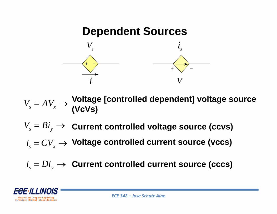
Dependent Sources
s xV AV
s yV Bi
s xi CV
s yi Di
Voltage [controlled dependent] voltage source (VcVs)
Current controlled voltage source (ccvs)
Voltage controlled current source (vccs)
Current controlled current source (cccs)
sV si
i V

ECE 342 – Jose Schutt‐Aine
Voltage controlled current source(vccs)
2s xi V
KCL:1 1
322 2
xx x
Vi V i V
14 2 xi V
2 ,xV V 1 3i A
4V
2 1i
xV 2
4
2 xV

ECE 342 – Jose Schutt‐Aine
Current controlled voltage source(ccvs)
KCL:
12d bV i
3b di i
3 2 3 1d bi i A
3V 3A
dibi
bV
2

ECE 342 – Jose Schutt‐Aine
• Principle– Any linear two-terminal network consisting of current or voltage
sources and impedances can be replaced by an equivalent circuit containing a single voltage source in series with a single impedance.
• Application– To find the Thevenin equivalent voltage at a pair of terminals, the load
is first removed leaving an open circuit. The open circuit voltage across this terminal pair is the Thevenin equivalent voltage.
– The equivalent resistance is found by replacing each independent voltage source with a short circuit (zeroing the voltage source), replacing each independent current source with an open circuit (zeroing the current source) and calculating the resistance between the terminals of interest. Dependent sources are not replaced and can have an effect on the value of the equivalent resistance.
Thevenin EquivalentNetwork Vth
+-
Zth
21
ECE 342 – Jose Schutt‐Aine
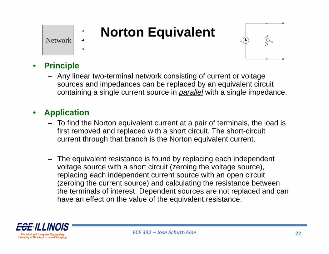
• Principle– Any linear two-terminal network consisting of current or voltage
sources and impedances can be replaced by an equivalent circuit containing a single current source in parallel with a single impedance.
• Application– To find the Norton equivalent current at a pair of terminals, the load is
first removed and replaced with a short circuit. The short-circuit current through that branch is the Norton equivalent current.
– The equivalent resistance is found by replacing each independent voltage source with a short circuit (zeroing the voltage source), replacing each independent current source with an open circuit (zeroing the current source) and calculating the resistance between the terminals of interest. Dependent sources are not replaced and can have an effect on the value of the equivalent resistance.
Norton EquivalentIth GthNetwork
22

ECE 342 – Jose Schutt‐Aine
KCL law at node A’ gives 1+Iy = IxAlso KVL gives 10=2Iy+3IxCombining these equations gives Ix = 2.4 mAFrom which we calculateVx = Vth=3(2.4)=7.2 V
kth( 2 )( 3 )R 1.2
2 3
Thevenin Equivalent - Example
Circuit for calculating impedance
Calculating Thevenin voltage
23
ECE 342 – Jose Schutt‐Aine
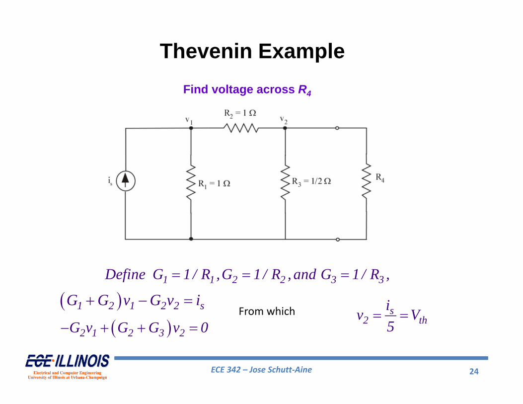
1 2 1 2 2 sG G v G v i
2 1 2 3 2G v G G v 0 From which s
2 thiv V5
1 1 2 2 3 3Define G 1 / R ,G 1 / R , and G 1 / R ,
Thevenin ExampleFind voltage across R4
24

ECE 342 – Jose Schutt‐Aine
R1
R2
R3Zth
Circuit for calculating impedance(current source is replaced with open circuit)
1 2 3th 1 2 3
1 2 3
( R R )R 2R ( R R ) RR R R 5
Thevenin Equivalent
25

ECE 342 – Jose Schutt‐Aine
Circuit with Thevenin Equivalent
4 so
4
R i / 5v ( t )2 / 5 R
VTH
ZTH
26

ECE 342 – Jose Schutt‐Aine
Transfer Function Representation
Use a two‐terminal representation of system for input and output
27

ECE 342 – Jose Schutt‐Aine
Y-parameter Representation
1 11 1 12 2
2 21 1 22 2
I y V y VI y V y V
28

ECE 342 – Jose Schutt‐Aine
Y Parameter Calculations
2 2
1 211 21
1 10 0V V
I Iy yV V
To make V2= 0, place a short at port 2
29

ECE 342 – Jose Schutt‐Aine
Z Parameters
1 11 1 12 2
2 21 1 22 2
V z I z IV z I z I
30
ECE 342 – Jose Schutt‐Aine
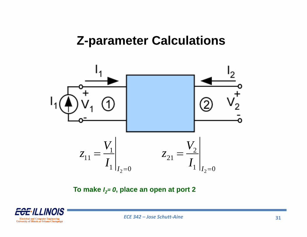
Z-parameter Calculations
2 2
1 211 21
1 10 0I I
V Vz zI I
To make I2= 0, place an open at port 2
31

ECE 342 – Jose Schutt‐Aine
H Parameters
1 11 1 12 2
2 21 1 22 2
V h I h VI h I h V
32

ECE 342 – Jose Schutt‐Aine
H Parameter Calculations
To make V2= 0, place a short at port 2
2 2
1 211 21
1 10 0V V
V Ih hI I
33

ECE 342 – Jose Schutt‐Aine
G Parameters
1 11 1 12 2
2 21 1 22 2
I g V g IV g V g I
34

ECE 342 – Jose Schutt‐Aine
G-Parameter Calculations
2 2
1 211 21
1 10 0I I
I Vg gV V
To make I2= 0, place an open at port 2
35


