UK 2187 VII(1) Issue Date: Valid Until: Reference No: 04 October 2012 12 January 2022 TS14/0001 Signatory: for P R Dixon Chief Executive National Measurement Office | Stanton Avenue | Teddington | TW11 0JZ | United Kingdom Tel +44 (0)20 8943 7272 | Fax +44 (0)20 8943 7270 | Web www.bis.gov.uk/nmo EEC type-examination certificate UK 2187 Revision 2 issued by The National Measurement Office In accordance with the provisions of regulation 8(5) of the Measuring Instruments (EEC Requirements) Regulations 1988 (SI 1988 No 186) which implement in the United Kingdom the Council Directives 71/316/EEC as amended and 86/217/EEC relating to tyre pressure gauges for motor vehicles, this certificate of EEC type- examination has been issued to: Pneumatic Components Limited Holbrook Rise Holbrook Industrial Estate Sheffield S20 3GE in respect of: A tyre pressure gauge for motor vehicles model: PAVEMENT GAUGE. maximum operating pressure: 10 bar The necessary data (principal characteristics, alterations, securing, functioning etc) for identification purposes, including alternative models and conditions (when applicable), are set out in the descriptive annex to this certificate. This revision replaces previous versions of the certificate.
Transcript
UK 2187
VII(1)
Issue Date: Valid Until:Reference No:
04 October 201212 January 2022TS14/0001
Signatory:for
P R DixonChief Executive
National Measurement Office | Stanton Avenue | Teddington | TW11 0JZ | United KingdomTel +44 (0)20 8943 7272 | Fax +44 (0)20 8943 7270 | Web www.bis.gov.uk/nmo
EEC type-examination certificate UK 2187 Revision 2issued by
The National Measurement Office
In accordance with the provisions of regulation 8(5) of the Measuring Instruments (EEC Requirements) Regulations 1988 (SI 1988 No 186) which implement in the United Kingdom the Council Directives 71/316/EEC as amended and 86/217/EEC relating to tyre pressure gauges for motor vehicles, this certificate of EEC type-examination has been issued to:
in respect of: A tyre pressure gauge for motor vehicles model: PAVEMENT GAUGE.maximum operating pressure: 10 bar
The necessary data (principal characteristics, alterations, securing, functioning etc) for identification purposes, including alternative models and conditions (when applicable), are set out in the descriptive annex to this certificate.
This revision replaces previous versions of the certificate.
2/14
Descriptive Annex1 REGULATIONS
The measuring instrument in respect of which this certificate of EEC type examination has been issued is subject to the provisions and requirements of the requirements of the Measuring Instruments (EEC Requirements) Regulations 1988 (SI 1988 No 186) as amended which implement in the United Kingdom the Council Directive No 73/362/EEC as amended by Directives 78/629/EEC and 85/146/EEC.
2 DESCRIPTION OF THE PATTERN
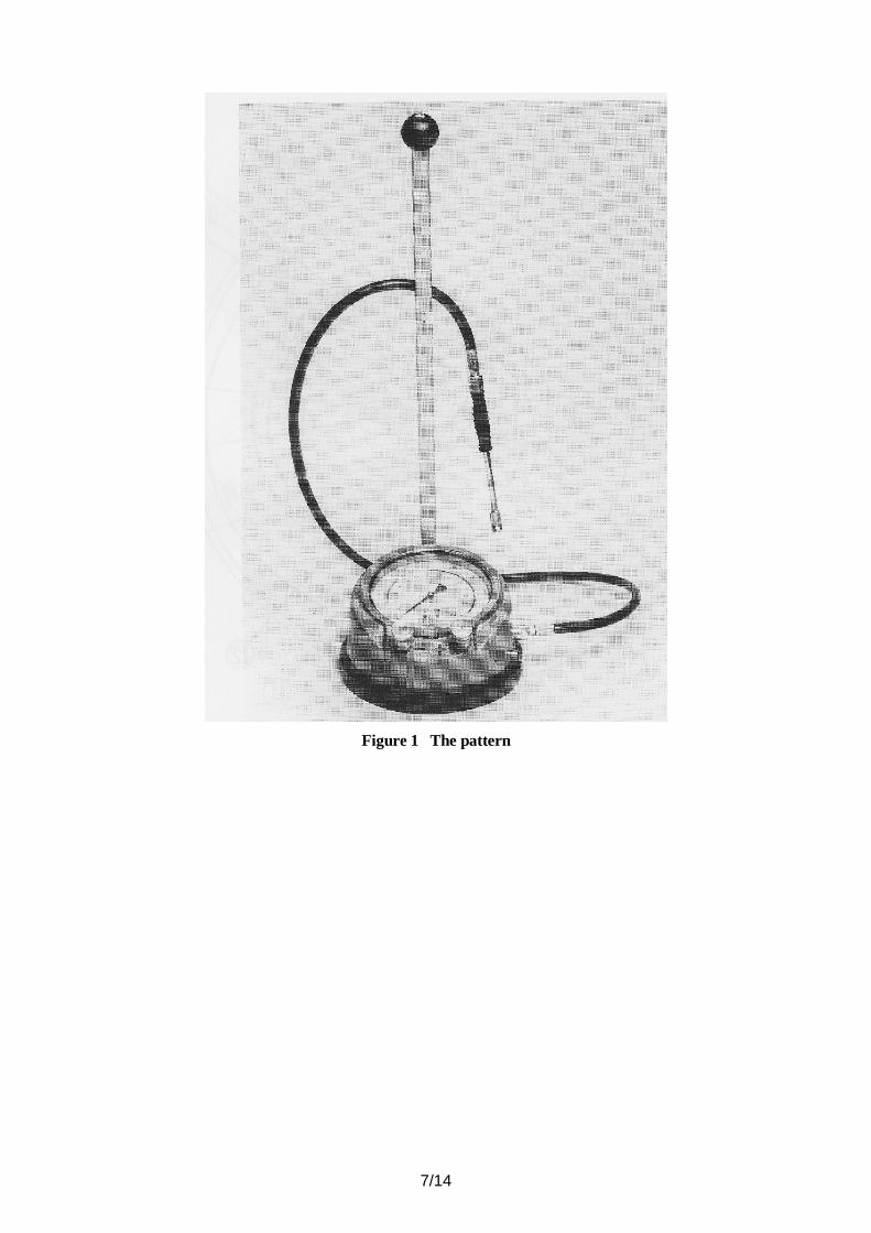
This pattern of a free-standing motor vehicle road tyre pressure gauge, as shown in Figure 1, comprises a gauge and pneumatic hose assembly with a tyre inflation/deflation control unit.
The system allows:
(i) measurement of road tyre pressure(ii) inflation of tyre pressure(iii) deflation of tyre pressure.
The maximum pressure capable of being measured is 10 bar (gauge)
3 CONSTRUCTION
3.1 Mechanical
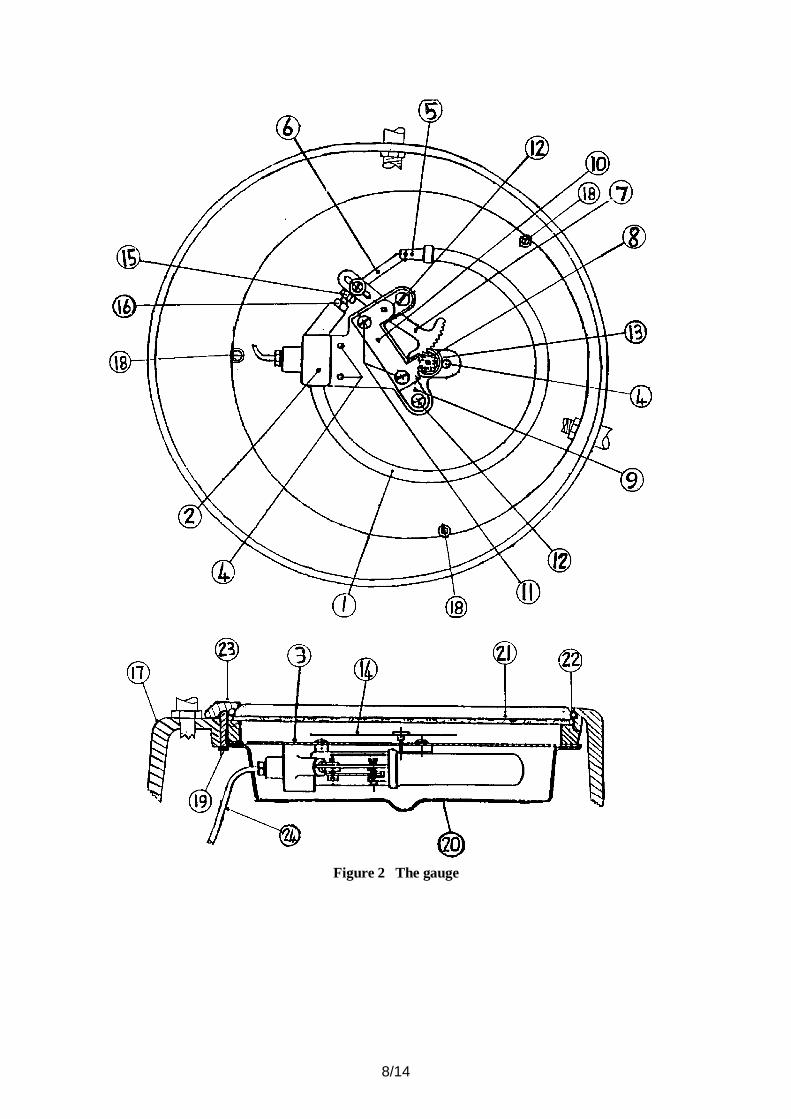
The gauge (Figure 2) consists of a phosphor bronze bourdon tube (1) soldered at one end to the gauge chassis (2) which is bolted to the rear of the faceplate (3) with three bolts (4). The free end of the tube has soldered fitting (5) providing a pivoted mount for adjustable connecting link (6) to the quadrant rack (7) interfacing with pinion (8). Two mounting plates (9) and (10) locate the quadrant rack pivot spindle and pinion spindle, held apart by two cylindrical tube spacers through which two screws (11) hold the assembly together. A laminated plastic gasket is compressed between mount plate (9) and the chassis which are bolted together with two bolts (12). Mounted on the tapered pinion spindle is hair spring (13) being also located on the adjacent cylindrical spacer, the spindle protrudes through the chassis and faceplate and locates a black coloured knife edged pointer (14). Bolt (15) and nut (16) provide an under range stop. Metal casing (17) houses the gauge which is retained in position by three screws (18) also securing plastic cover (20). The translucent window (21) through which the gauge is viewed is held in position by metal clip (22) and metal clamp (23) being secured by bolt (19). Pneumatic input to the bourdon tube is through a 2 mm nylon tube (24) having a threaded compression fitting at either end, being assembled to both the gauge chassis and inflation valve assembly (1 - Figure 3).
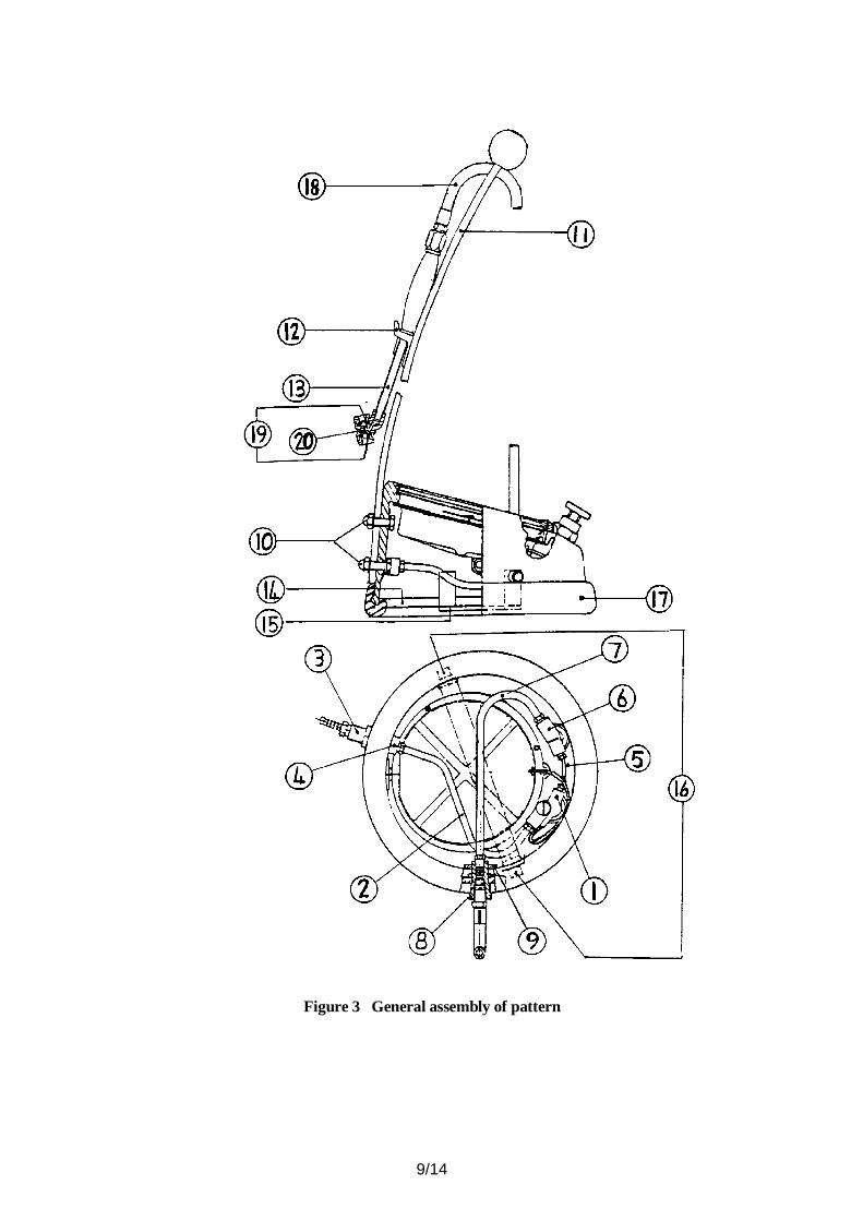
The inflation valve assembly is secured to the casing with a threaded female fastener (1 - Figure 5) nylon hose (2) (Figure 3) having a threaded compression fitting at either end is assembled to the inflation valve and the pneumatic inlet fitting (3) which is secured to the casing with locknut (4). Nylon hose (5) having a threaded compression fitting at either end is assembled to the inflation valve and deflation valve (6) which is secured to the casing with threaded female fastener (2) (Figure 5). Nylon hose (7 - Figure 3) having a threaded compression fitting at either end is assembled to the deflation valve and the pneumatic outlet fitting (8) which is secured to the casing by locknut (9). Bolted to the casing by two bolts (10) is carrying handle (11) on which a stowage fitting (12) is riveted for the tyre valve connector unit (13). Metal cover (14) is located at the base of the casing by metal retaining bar (15) which is secured to the casing by two bolts (16). Rubber surround (17) is mounted on the base of the casing.
3/14
In Figure 3, the pneumatic hose assembly (18) consists of a nylon reinforced concentric hose, terminated at either end with a crimped fitting having a fixed male parallel thread, being assembled to the tyre valve connector unit and pneumatic outlet fitting. The tyre valve connector unit has two in-line hold-on ports, in each of which is located a non-metallic seal (19) and a free-moving valve (20).
3.2 Display
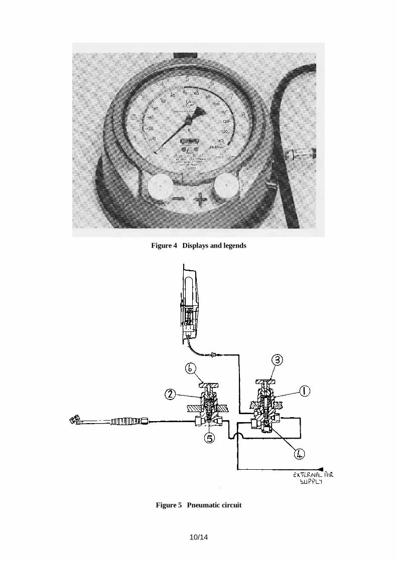
The gauge faceplate (Figure 4) indicates a pressure range of 0 to 10 bar, each one tenth of a bar is shown by a red graduation line with every fifth line being of greater length. Each bar, including the zero, is permanently marked in red. Extending over the pressure range of 1.4 bar to 4.5 bar is a yellow coloured overlay.
The gauge faceplate also carries an additional pressure range scale, 0 to 140 lbf/in², marked in black and arranged on a lesser radius than the bar scale.
3.3 Technical data
pressure range: 0 to 10 barscale graduations: 0.1 barfaceplate (mounted): 160 mm diameter (nominal)pointer radius: 63 mm (nominal)bar scale radius: 61 mm (nominal)bar scale arc: 270 (nominal)bourdon tube: 115 mm diameter (nominal)operating temperature range: - 10 C to + 40 Coverall height: 720 mm (nominal)length of pneumatic hose: 1570 mm (minimum)(excluding inflation/deflation control)
3.4 Sealing and stamping
In Figure 3, the two bolts (16) securing retaining bar (15) also locate and retain metal cups which are undercut, and in which lead seals are fixed for stamping.
4 OPERATION
Figure 5 shows the pneumatic circuit, to obtain the vehicle tyre pressure the tyre connector (13 - Figure 3) is pushed onto the tyre valve, the connector valve (20 - Figure 3) then depresses the tyre valve so enabling the pressure to be communicated to the bourdon tube.
To increase the vehicle tyre pressure, the foot operated inflation button (3 - Figure 5) which is adjacent to the red coloured addition mark, is depressed, unseating spring loaded valve (4 - Figure 5) enabling mains supplied air to enter the tyre. Allowing the inflation button to return to its rest position restores the gauge line permitting tyre pressure to be indicated on the gauge.
To decrease tyre pressure, the foot operation deflation button (6 - Figure 5) which is adjacent to the red coloured minus mark is depressed, unseating spring loaded valve (5 - Figure 5) and allowing air from the tyre to vent to atmosphere through the deflation button housing. Allowing the deflation button to return to its rest position restores the gauge line permitting tyre pressure to be indicated on the gauge.
The gauge operates using a bourdon tube mechanism. Vehicle tyre pressure is indicated on the gauge by air entering the elliptical shaped bore of the bourdon tube (1 - Figure 2) exerting a pressure on the free end of the tube causing it to move radially. This movement is transmitted by the adjustable connecting link (6) to the quadrant rack (7) which rotates about its pivot and drives the pinion (8). The rotating movement of the pinion is transmitted by its spindle to the knife-edged pointer (14). The hair spring (13) acts on the pinion to eliminate any lost motion between it and the quadrant rack and the laminated gasket reduces mechanical shock to the mechanism.
4/14
5 INSCRIPTIONS
5.1 The following inscriptions are marked on the faceplate:
(i) PCL AIR TECHNOLOGY(ii) ONLY bar SCALED APPROVED(iii) Pe(iv) 15
(v) THE SIGN OF EEC PATTERN APPROVAL(vi) IMPORTANT
TO REGISTER TYRE PRESSURE RELEASE INFLATOR LEVERBUTTON (+) MUST BE RELEASED
5.2 The unit of denomination "bar" is marked adjacent to the red coloured numeral “10”. An adhesive label affixed to the air receiver identifies the instrument as a “PAVEMENT GAUGE”.
5.3 The casing of the instrument, adjacent to the foot operated inflation valve, is inscribed: + , and adjacent to the deflation valve: - . Both inscriptions being coloured red.
6 AUTHORISED ALTERNATIVES
6.1 Having the inflation/deflation control unit with a single hold-on tyre valve connector, as shown in Figure 6a.
6.2 Having the inflation/deflation control unit with a single clip-on tyre valve connector, as shown in Figure 6b.
6.3 Having the inflation/deflation control unit with a twin clip-on tyre valve connector, as shown in Figure 6c.
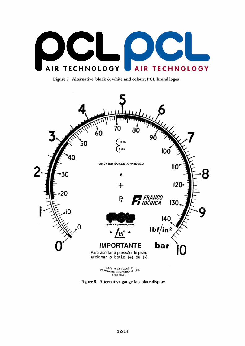
6.4 Having alternative PCL brand logos for the dial face and any affixed labels, as shown in Figure 7.
6.5 Having the modification that the gauge faceplate is additionally marked with the alternative trade name "FI FRANCO IBERICA" and the instructions legend headed "IMPORTANT", as illustrated in Figure 8.
6.6 Having the modification that the gauge faceplate may be marked with any additional alternative trade name and the instructions legend headed "IMPORTANT" may be printed in any alternative translation. The gauge faceplate carries the legend "MADE IN ENGLAND BY PNEUMATIC COMPONENTS LTD SHEFFIELD". The manufacturer's logo PCL, may be omitted.
6.7 Having the following modifications:
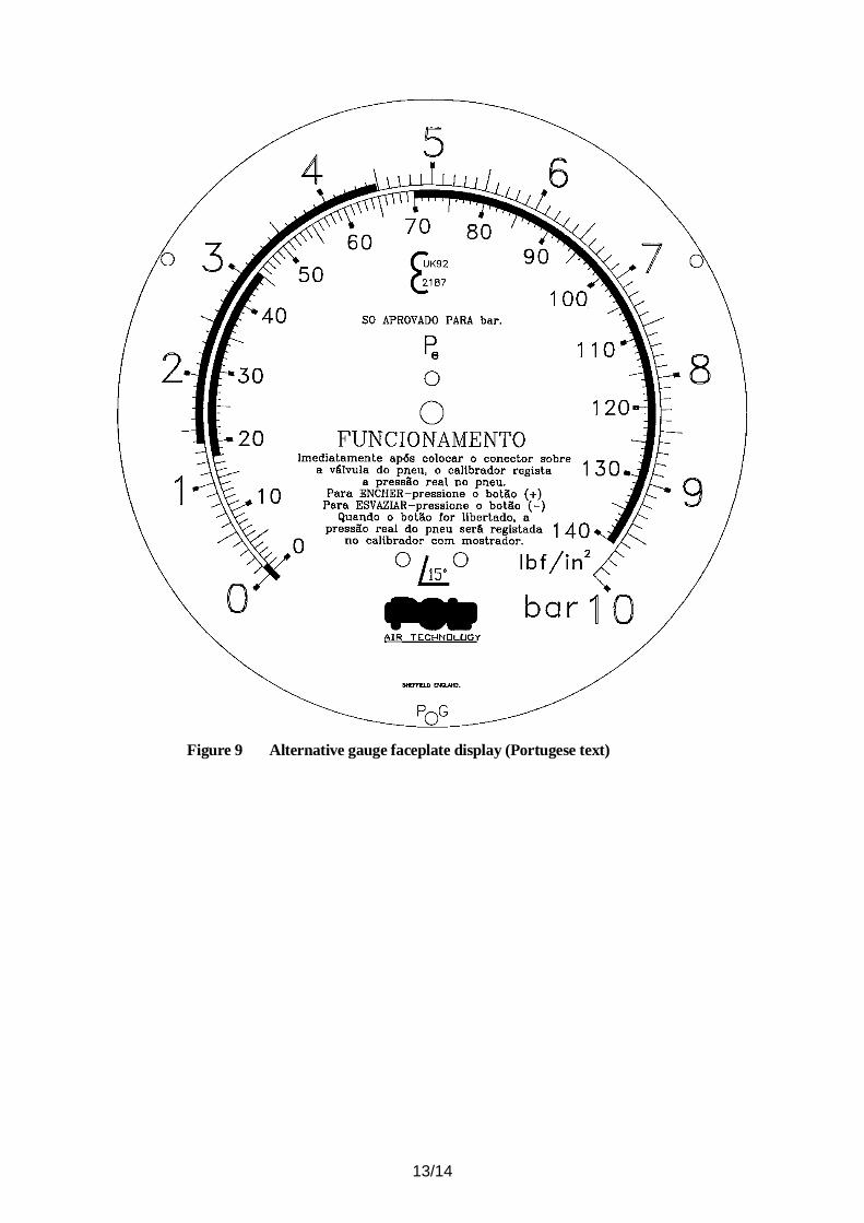
(i) The scales and text may be in different colours provided they are legible and do not cause confusion.
(ii) The text on the dial face, including instructions on the use of the gauge, may be translated into any language, e.g. Portuguese (Figure 9)
[The definitive English version is given below.]
"OPERATION
Immediately the connector is placed on the tyre valve, the gauge will register the actual pressure in the tyre.
To INFLATE - depress button (+)
To DEFLATE - depress button (-)
On release of buttons, actual tyre pressure will be registered on the dial gauge".
5/14
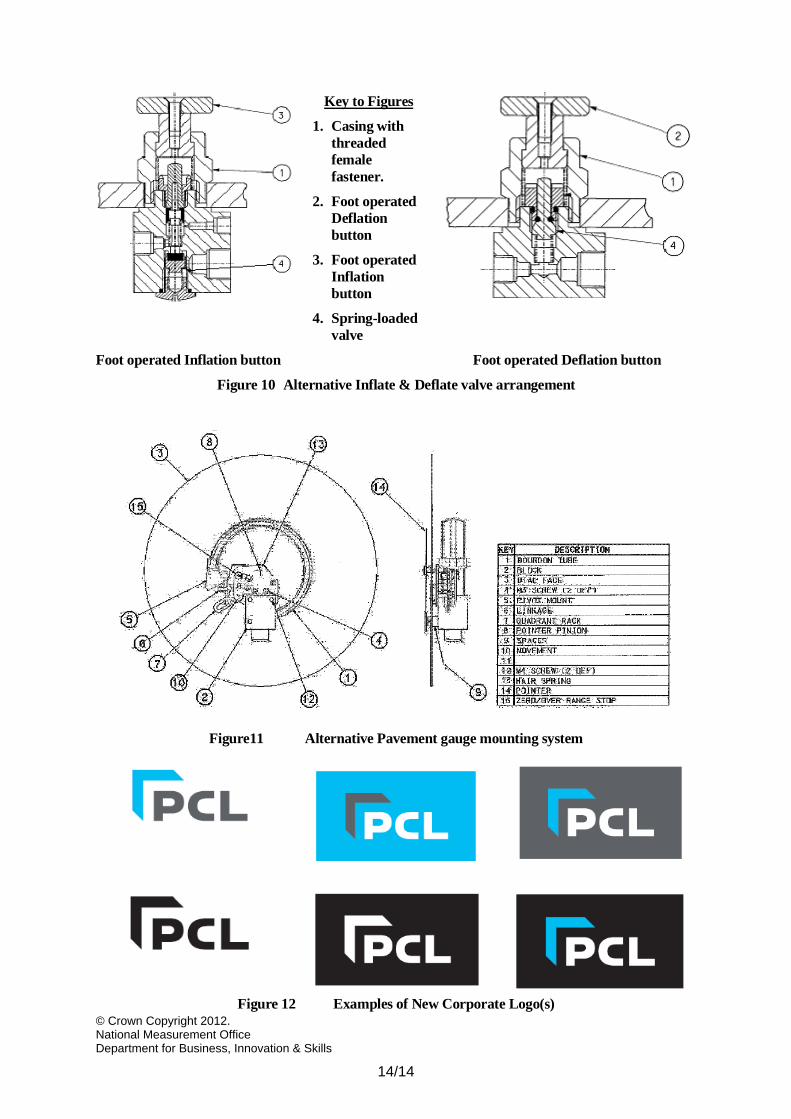
6.8 Having the following modifications:
(i) The seal, of the Inflate valve arrangement, has been changed from a washer to an ‘O’ ring.
(ii) The flat face sealing “poppet”, of the Deflate valve arrangement, has been replaced by an ‘O’ ring which seals against the cone.
(iii) The valve arrangements may be constructed from brass machined billets instead of from brass machined stampings.
The alternative Inflate & Deflate valve arrangements are as shown in Figure 10.
6.9 Having the modification of a simplified bourdon tube mounting system. The external appearance remains unchanged except that three mounting screws are now visible below the pointer in the faceplate. The mounting system is shown in Figure 11.
6.10 Having alternative New Corporate Logo(s) for the dial face and any affixed labels, as shown in Figure 12.
7 ILLUST RATIONS
Figure 1 The patternFigure 2 The gaugeFigure 3 General assembly of patternFigure 4 Displays and legendsFigure 5 Pneumatic circuitFigure 6 Alternative inflation/deflation control unitsFigure 7 Alternative, black & white and colour, PCL brand logosFigure 8 Alternative gauge faceplate displayFigure 9 Alternative gauge faceplate displayFigure 10 Alternative Inflate & Deflate valve arrangementFigure 11 Alternative Pavement gauge mounting systemFigure 12 Examples of New Corporate Logo(s)
6/14
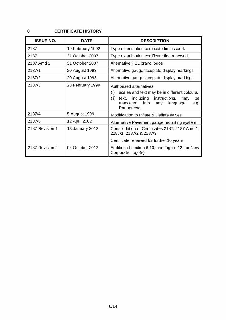
8 CERTIFICATE HISTORY
ISSUE NO. DATE DESCRIPTION
2187 19 February 1992 Type examination certificate first issued.
2187 31 October 2007 Type examination certificate first renewed.
2187 Amd 1 31 October 2007 Alternative PCL brand logos
2187/1 20 August 1993 Alternative gauge faceplate display markings
2187/2 20 August 1993 Alternative gauge faceplate display markings
2187/3 28 February 1999 Authorised alternatives:
(i) scales and text may be in different colours.
(ii) text, including instructions, may be translated into any language, e.g.Portuguese.
2187/4 5 August 1999 Modification to Inflate & Deflate valves
2187/5 12 April 2002 Alternative Pavement gauge mounting system
2187 Revision 1 13 January 2012 Consolidation of Certificates:2187, 2187 Amd 1, 2187/1, 2187/2 & 2187/3.
Certificate renewed for further 10 years
2187 Revision 2 04 October 2012 Addition of section 6.10, and Figure 12, for New Corporate Logo(s)
7/14
Figure 1 The pattern
8/14
Figure 2 The gauge
9/14
Figure 3 General assembly of pattern
10/14
Figure 4 Displays and legends
Figure 5 Pneumatic circuit
11/14
Figure 6 Alternative inflation/deflation control units, and separate hoses
12/14
Figure 7 Alternative, black & white and colour, PCL brand logos
Figure 8 Alternative gauge faceplate display
13/14
Figure 9 Alternative gauge faceplate display (Portugese text)


![COUNCIL REGULATIONS (EEC) No. 574/72 · The Law Relating to Social Security COUNCIL REGULATION (EEC) No. 574/72 EEC 574/72 Supplement No. 42 [Sept 97] 9.4001 COUNCIL REGULATIONS (EEC)](https://static.documents.pub/doc/80x56/5b52c4117f8b9ad8118d9caf/council-regulations-eec-no-57472-the-law-relating-to-social-security-council.jpg)
