ISSN 0104-6632 Printed in Brazil www.abeq.org.br/bjche Vol. 32, No. 02, pp. 519 - 529, April - June, 2015 dx.doi.org/10.1590/0104-6632.20150322s00002539 *To whom correspondence should be addressed Brazilian Journal of Chemical Engineering EFFECT OF ROTATION RATES ON THE LAMINAR FLOW AND HEAT TRANSFER PAST A CIRCULAR CYLINDER R. Bouakkaz 1* , K. Talbi 1 , M. Ouazzazi 2 , Y. Khelili 1 and F. Salhi 3 1 Département de Génie Mécanique, Université Constantine 1, Constantine, Algérie. E-mail: [email protected]; [email protected]; [email protected]2 Département de Génie Mécanique, Université Kasdi Merbah Ouargla, Algérie. E-mail: [email protected]3 Département de Génie Mécanique, Université Mouloud Mammeri Tizi Ouzou, Algérie. E-mail: [email protected](Submitted: February 11, 2013 ; Revised: April 1, 2013 ; Accepted: October 13, 2013) Abstract - In this work, forced convection heat transfer past a rotating circular cylinder with a constant non- dimensional rotation rate α varying from 0 to 6 was investigated for Reynolds numbers of 20–200 and a Prandtl number of 0.7. The numerical calculations are carried out by using a finite-volume method based commercial computational fluid dynamics solver FLUENT. The successive changes in the flow pattern are studied as a function of the rotation rate. Suppression of vortex shedding occurs as the rotation rate increases (α > 2). A second kind of instability appears for higher rotation speed where a series of counter-clockwise vortices is shed in the upper shear layer. The rotation attenuates the secondary instability and increases the critical Reynolds number for the appearance of this instability. In addition, time-averaged (lift and drag coefficients and Nusselt number) results were obtained and compared with the literature data. A good agreement was obtained for both the local and averaged values. Keywords: Unsteady regime; Rotating circular cylinder; Rotation rate; Nusselt number; Forced convection. INTRODUCTION Flow and heat transfer past a rotating cylinder has been a subject of great interest for researchers due to its high applicability in various industrial processes. The applications may include cylindrical cooling devices in plastics and glass industries, food process- ing and chemical processing industries. In these flows, the results depend not only on the Reynolds number (Re), but also on rotation rate (α), defined as the ratio of rotational velocity of the cylinder wall to the incoming free stream flow velocity, expressed as: Re=U ∞ D t /v and ( ) /2 t D U ∞ α=Ω (1) The flow around a rotating circular cylinder with a constant angular velocity, placed in a uniform stream, was investigated by Stojkovic et al. (2002) at Re = 60, 100 and 200, Mittal and Kumar (2003) at Re = 200 found two more flow transitions: a second transition from steady to unsteady flow at α L2 and a third transition at α > α L3 where unsteady flow is again suppressed. They found the second unsteady flow mode in a very narrow range of (α L2 ≤ α ≤ α L3 ). Also, Kang et al. (1999) found that drag and lift coefficients decrease with an increase in rotation rate. Badr and Dennis (1989) found a decrease in laminar forced convection heat transfer with increas- ing rotation rate for an isothermal cylinder for Re = 5, 10, 20, 40 and 100 at α ≤ 4. A well-organized
Transcript
ISSN 0104-6632 Printed in Brazil
www.abeq.org.br/bjche
Vol. 32, No. 02, pp. 519 - 529, April - June, 2015 dx.doi.org/10.1590/0104-6632.20150322s00002539
*To whom correspondence should be addressed
Brazilian Journal of Chemical Engineering
EFFECT OF ROTATION RATES ON THE LAMINAR FLOW AND HEAT TRANSFER PAST
A CIRCULAR CYLINDER
R. Bouakkaz1*, K. Talbi1, M. Ouazzazi2, Y. Khelili1 and F. Salhi3
(Submitted: February 11, 2013 ; Revised: April 1, 2013 ; Accepted: October 13, 2013)
Abstract - In this work, forced convection heat transfer past a rotating circular cylinder with a constant non-dimensional rotation rate α varying from 0 to 6 was investigated for Reynolds numbers of 20–200 and a Prandtl number of 0.7. The numerical calculations are carried out by using a finite-volume method based commercial computational fluid dynamics solver FLUENT. The successive changes in the flow pattern are studied as a function of the rotation rate. Suppression of vortex shedding occurs as the rotation rate increases (α > 2). A second kind of instability appears for higher rotation speed where a series of counter-clockwise vortices is shed in the upper shear layer. The rotation attenuates the secondary instability and increases the critical Reynolds number for the appearance of this instability. In addition, time-averaged (lift and drag coefficients and Nusselt number) results were obtained and compared with the literature data. A good agreement was obtained for both the local and averaged values. Keywords: Unsteady regime; Rotating circular cylinder; Rotation rate; Nusselt number; Forced convection.
INTRODUCTION
Flow and heat transfer past a rotating cylinder has been a subject of great interest for researchers due to its high applicability in various industrial processes. The applications may include cylindrical cooling devices in plastics and glass industries, food process-ing and chemical processing industries. In these flows, the results depend not only on the Reynolds number (Re), but also on rotation rate (α), defined as the ratio of rotational velocity of the cylinder wall to the incoming free stream flow velocity, expressed as: Re=U∞Dt /v and
( )/ 2tD U∞α = Ω (1)
The flow around a rotating circular cylinder with a constant angular velocity, placed in a uniform stream, was investigated by Stojkovic et al. (2002) at Re = 60, 100 and 200, Mittal and Kumar (2003) at Re = 200 found two more flow transitions: a second transition from steady to unsteady flow at αL2and a third transition at α > αL3 where unsteady flow is again suppressed. They found the second unsteady flow mode in a very narrow range of (αL2 ≤ α ≤ αL3). Also, Kang et al. (1999) found that drag and lift coefficients decrease with an increase in rotation rate. Badr and Dennis (1989) found a decrease in laminar forced convection heat transfer with increas-ing rotation rate for an isothermal cylinder for Re = 5, 10, 20, 40 and 100 at α ≤ 4. A well-organized
520 R. Bouakkaz, K. Talbi, M. Ouazzazi, Y. Khelili and F. Salhi
Brazilian Journal of Chemical Engineering
numerical study was also published by Ingham (1990). In that paper, the Navier–Stokes equations were solved via the finite difference method in order to examine the asymmetrical flow in a uniform vis-cous liquid at Re numbers 5 and 20 and dimen-sionless ratios α from 0 to 0.5.
Furthermore, Yan and Zu (2008) carried out numerical simulation for Re = 200, 500 and 1000, 0 ≤ α ≤ 1 and 0.1 ≤ Pr ≤ 1. Nemati et al. (2010) in-vestigated the laminar flow and heat transfer from a rotating circular cylinder with uniform planar shear, where the free stream velocity varies linearly across the cylinder using Multi-Relaxation-Time (MRT) LBM. Recently, Nobari et al. (2010) studied the convective heat transfer from a rotating cylinder with inline oscillation at Re numbers of 100, 200, and 300. Different rotational speeds of the cylinder (0-2.5) were considered at various oscillating ampli-tudes and frequencies with three different Pr num-bers of 0.7, 6, and 20.
Paramane et al. (2009) investigated numerically the forced convection heat transfer across a rotating circular cylinder in the 2-D laminar regime. They concluded that the rotation can be used as a drag reduction and heat transfer suppression technique. Subsequently, Paramane et al. (2010) studied nu-merically the free stream flow and forced convection heat transfer across a rotating cylinder, dissipating heat flux for Reynolds numbers of 20-160 and a Prandtl number of 0.7. Their results show that, at higher rotational velocity, the Nusselt number is almost independent of Reynolds number and the thermal boundary conditions. The suppression of the von Karman vortex street was also reported numeri-cally by Hu et al. (1996) and experimentally by Dol et al. (2008) and Lam (2009) for isothermal flow.
The objective of the present study was to investi-gate numerically the flow and heat transfer char-acteristics of a rotating circular cylinder for a wide
range of Reynolds numbers (20 ≤ Re ≤ 200) and a Prandtl number of 0.7 for rotation parameters (0 ≤ α ≤ 6) in the two-dimensional laminar flow regime.
PROBLEM STATEMENT, GOVERNING EQUATIONS, AND BOUNDARY CONDITIONS
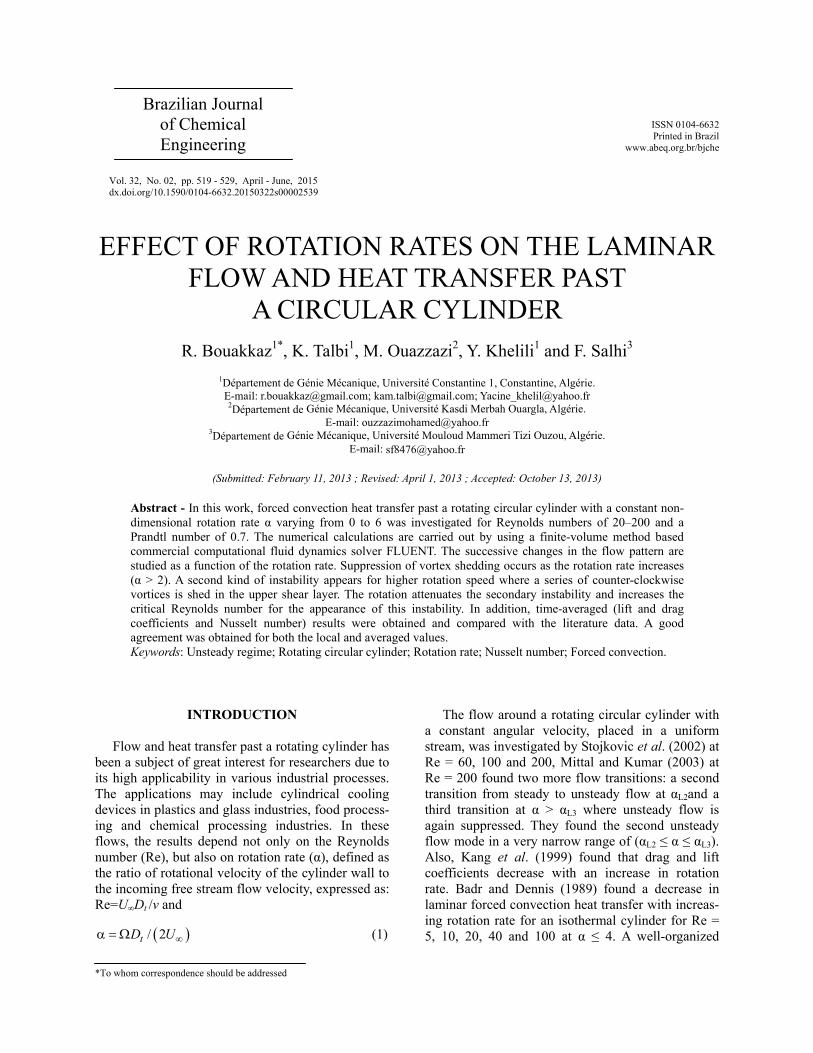
The system here consists of a 2-D infinitely long circular cylinder (Figure 1) having a diameter Dt which is maintained at a constant temperature Tw and is rotating in a counter-clockwise direction with a constant angular velocity of Ω. It is exposed to a constant free stream velocity of U∞ at a uniform tem-perature of T∞ at the inlet. The temperature differ-ence between the streaming liquid and the surface of the cylinder is small (= 2 K); therefore, the variation of physical properties, particularly density and vis-cosity, with temperature could be neglected.
The governing partial differential equations here are the Navier-Stokes and energy equations in two dimensions for the incompressible flow around a rotating circular cylinder: - Continuity equation
0U VX Y∂ ∂
+ =∂ ∂
(2)
- X-momentum equation
2 2
2 2( ) ( ) ( ) 1 ( ) ( )
Re⎛ ⎞∂ ∂ ∂ ∂ ∂ ∂
+ + =− + +⎜ ⎟⎜ ⎟∂τ ∂ ∂ ∂ ∂ ∂⎝ ⎠
U UU VU P U UX Y X X Y
(3)
- Y-momentum equation
2 2
2 2( ) ( ) ( ) 1 ( ) ( )
Re⎛ ⎞∂ ∂ ∂ ∂ ∂ ∂
+ + = − + +⎜ ⎟⎜ ⎟∂τ ∂ ∂ ∂ ∂ ∂⎝ ⎠
V UV VV P V VX Y Y X Y
(4)
-100 0 100X
-100
-50
0
50
100
150
Y
b
φ
H= 125D
Symmetry
Inlet
Symmetry
a
Tw
α
Ω Outlet
-1 0 1X
-1
-0.5
0
0.5
1
Y
c
Dt
-100 0 100X
-100
-50
0
50
100
150
Y
b
-100 0 100X
-100
-50
0
50
100
150
Y
b
φ
H= 125D
Symmetry
Inlet
Symmetry
a
Tw
α
Ω Outletφ
H= 125D
Symmetry
Inlet
Symmetry
a
Tw
α
Ωφ
H= 125D
Symmetry
Inlet
Symmetry
a
Tw
α
Ω Outlet
-1 0 1X
-1
-0.5
0
0.5
1
Y
c
Dt
-1 0 1X
-1
-0.5
0
0.5
1
Y
c
Dt
Figure 1: (a) Schematic of the unconfined flow and heat transfer around a rotating circular cylinder. (b) Grid structure. (c) Close-up view in the vicinity of the cylinder.
Effect of Rotation Rates on the Laminar Flow and Heat Transfer Past a Circular Cylinder 521
Brazilian Journal of Chemical Engineering Vol. 32, No. 02, pp. 519 - 529, April - June, 2015
- Energy equation
2 2
2 2( ) ( ) ( ) 1 ( ) ( )
Re PrU VX Y X Y
⎛ ⎞∂ θ ∂ θ ∂ θ ∂ θ ∂ θ+ + = +⎜ ⎟⎜ ⎟∂τ ∂ ∂ ∂ ∂⎝ ⎠
(5)
with
2
, , , ,
,
t t t
w
u v tU x yU V X YU U D D D
p T TPT TU
∞
∞ ∞
∞
∞∞
= = τ = = =
−= θ =
−ρ
Boundary Conditions
The dimensionless boundary conditions for the flow across a rotating circular cylinder can be written as (Figure 1): The left-hand arc (Figure 1(a)) is the inflow section or upstream section, where there is a Dirichlet-type boundary condition for the Cartesian velocity components,
1, 0 0.U V and= = θ = (6)
The right-hand arc represents the outflow bound-ary, where it is considered that the diffusion flux in the direction normal to the exit surface is zero for all variables
( 0)∂ ∂ ∂θ= = =∂ ∂ ∂U V
X X X (7)
On the straight horizontal segments, a zero nor-mal velocity and a zero normal gradient of all vari-ables are prescribed:
( 0)U VY X∂ ∂θ= = =∂ ∂ (8)
As a consequence, a zero shear stress condition is
imposed at these two boundaries. The sectors of the circle that contain these segments have a span of 10 each. The inclusion of these segments defines a tran-sition region between the inlet and outlet sections. Finally, the dimensionless peripheral or tangential velocity is prescribed on the surface of the rotating cylinder, along with a no-slip boundary condition ( sin( ); cos( ), 1)U V= −α φ = −α φ θ = (9) Force Coefficients
Two relevant parameters computed from the velocity and pressure fields are the drag and lift coef-ficients, which represent dimensionless expressions
of the forces that the fluid produces on the circular cylinder. These are defined, respectively, as follows:
2Dt
DCU D∞
=ρ
2Lt
LCU D∞
=ρ
(10)
where Dt is the drag force and L is the lift force with respect to the centre of the cylinder.
NUMERICAL DETAILS
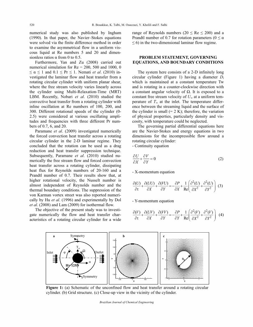
The computational grid for the problem under consideration was generated by using a commercial grid generator GAMBIT and the numerical calcula-tions were performed in the full computational do-main using FLUENT for varying conditions of Re number and rotation rate. This computer program applies a control-volume method to integrate the equations of motion, constructing a set of discrete algebraic equations with conservative properties. In particular, the O-type grid modified structure similar to that adopted by Kang et al. (1999) was created here. The unsteady, laminar, segregated solver was employed here to solve the incompressible flow on the collocated grid arrangement. An implicit scheme was applied to obtain the discretized system of equa-tions. The sequence updates the velocity field through the solution of the momentum equations using known values for pressure and velocity. Then, it solves a ‘Poisson-type’ pressure correction equa-tion obtained by combining the continuity and mo-mentum equations. A quadratic upwind interpolation for convective kinematics (QUICK) scheme was used to discretize the convective term in the momen-tum equations, whereas the diffusive term is discre-tized by a central difference scheme. Pressure-im-plicit with splitting of operators (PISO) was selected as the pressure-velocity coupling scheme. Finally, the time integration of the unsteady momentum equations was performed using a second-order approximation. Domain Independence Study
The mesh used for all the two-dimensional com-putations consisted of 26 720 quadrilateral cells and 26 880 nodes. The cylinder (of diameter D) resides in a computational domain whose outer boundary is a modified cylinder with edges located at a distance of H from the centre of the cylinder. There are Nt points in the circumferential direction on the cylinder surface and the radial thickness of the first layer of cells (i.e., cells attached to the wall) is hDt. A close-
522 R. Bouakkaz, K. Talbi, M. Ouazzazi, Y. Khelili and F. Salhi
Brazilian Journal of Chemical Engineering
up view of a typical mesh is shown in Figure 1. It can be observed that the mesh is very fine close to the cylinder and the cells become larger with increas-ing distance from the cylinder.
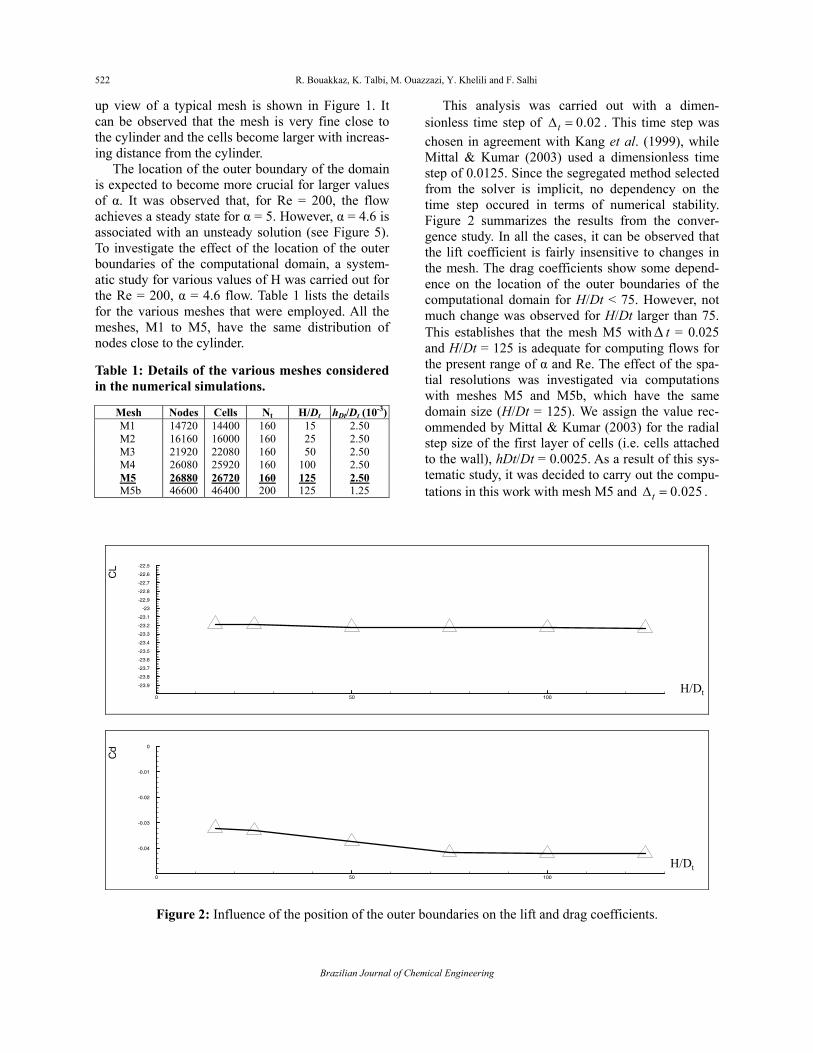
The location of the outer boundary of the domain is expected to become more crucial for larger values of α. It was observed that, for Re = 200, the flow achieves a steady state for α = 5. However, α = 4.6 is associated with an unsteady solution (see Figure 5). To investigate the effect of the location of the outer boundaries of the computational domain, a system-atic study for various values of H was carried out for the Re = 200, α = 4.6 flow. Table 1 lists the details for the various meshes that were employed. All the meshes, M1 to M5, have the same distribution of nodes close to the cylinder. Table 1: Details of the various meshes considered in the numerical simulations.
This analysis was carried out with a dimen-sionless time step of 0.02tΔ = . This time step was chosen in agreement with Kang et al. (1999), while Mittal & Kumar (2003) used a dimensionless time step of 0.0125. Since the segregated method selected from the solver is implicit, no dependency on the time step occured in terms of numerical stability. Figure 2 summarizes the results from the conver-gence study. In all the cases, it can be observed that the lift coefficient is fairly insensitive to changes in the mesh. The drag coefficients show some depend-ence on the location of the outer boundaries of the computational domain for H/Dt < 75. However, not much change was observed for H/Dt larger than 75. This establishes that the mesh M5 withΔ t = 0.025 and H/Dt = 125 is adequate for computing flows for the present range of α and Re. The effect of the spa-tial resolutions was investigated via computations with meshes M5 and M5b, which have the same domain size (H/Dt = 125). We assign the value rec-ommended by Mittal & Kumar (2003) for the radial step size of the first layer of cells (i.e. cells attached to the wall), hDt/Dt = 0.0025. As a result of this sys-tematic study, it was decided to carry out the compu-tations in this work with mesh M5 and 0.025tΔ = .
0 50 100
-23.9
-23.8
-23.7
-23.6
-23.5
-23.4
-23.3
-23.2
-23.1
-23
-22.9
-22.8
-22.7
-22.6
-22.5
CL
H/Dt0 50 100
-23.9
-23.8
-23.7
-23.6
-23.5
-23.4
-23.3
-23.2
-23.1
-23
-22.9
-22.8
-22.7
-22.6
-22.5
CL
H/Dt
0 50 100
-0.04
-0.03
-0.02
-0.01
0
Cd
H/Dt0 50 100
-0.04
-0.03
-0.02
-0.01
0
Cd
H/Dt
Figure 2: Influence of the position of the outer boundaries on the lift and drag coefficients.
Effect of Rotation Rates on the Laminar Flow and Heat Transfer Past a Circular Cylinder 523
Brazilian Journal of Chemical Engineering Vol. 32, No. 02, pp. 519 - 529, April - June, 2015
RESULTS AND DISCUSSION
In the present study, the governing parameters considered are as follows: Re = 20–200, Rotation rate (α): 0–6 with the Prandtl number fixed at 0.7. Comparison with Other Results
The first step was to validate the problem set-up, the choice of numerical methods and mesh attributes by comparing results from our numerical simulations with results obtained from the literature. This com-parison was performed with the numerical results of Mittal & Kumar (2003) for Re = 200. The outcomes included in the comparison were the lift and drag coefficients, as well as the dimensionless vorticity and pressure coefficient on the surface of the rotating circular cylinder. The dimensionless form of the vorticity is ϖ =2ωDt/U∞, while the pressure coeffi-cient is defined as:
212
pp pC
U∞
∞
−=
ρ (11)
where p∞ represents the pressure as the radial coordi-nate goes to infinity and p represents the pressure on the surface of the circular cylinder.
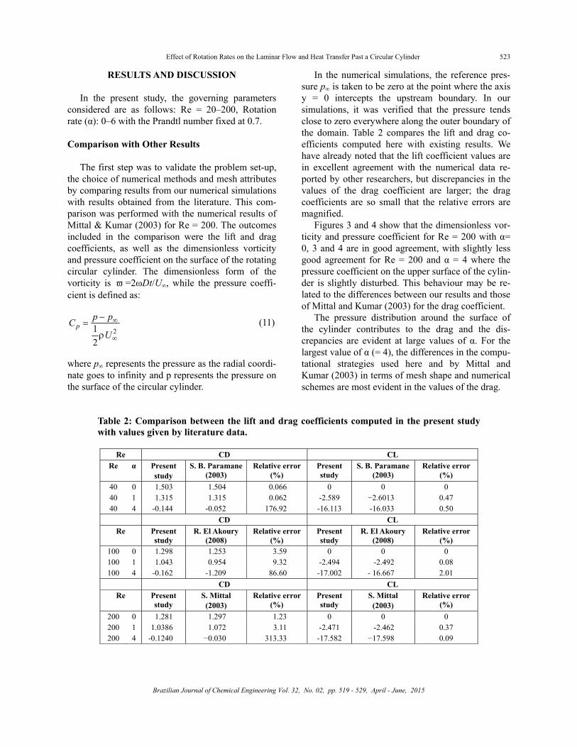
In the numerical simulations, the reference pres-sure p∞ is taken to be zero at the point where the axis y = 0 intercepts the upstream boundary. In our simulations, it was verified that the pressure tends close to zero everywhere along the outer boundary of the domain. Table 2 compares the lift and drag co-efficients computed here with existing results. We have already noted that the lift coefficient values are in excellent agreement with the numerical data re-ported by other researchers, but discrepancies in the values of the drag coefficient are larger; the drag coefficients are so small that the relative errors are magnified.
Figures 3 and 4 show that the dimensionless vor-ticity and pressure coefficient for Re = 200 with α= 0, 3 and 4 are in good agreement, with slightly less good agreement for Re = 200 and α = 4 where the pressure coefficient on the upper surface of the cylin-der is slightly disturbed. This behaviour may be re-lated to the differences between our results and those of Mittal and Kumar (2003) for the drag coefficient.
The pressure distribution around the surface of the cylinder contributes to the drag and the dis-crepancies are evident at large values of α. For the largest value of α (= 4), the differences in the compu-tational strategies used here and by Mittal and Kumar (2003) in terms of mesh shape and numerical schemes are most evident in the values of the drag.
Table 2: Comparison between the lift and drag coefficients computed in the present study with values given by literature data.
524 R. Bouakkaz, K. Talbi, M. Ouazzazi, Y. Khelili and F. Salhi
Brazilian Journal of Chemical Engineering
0 100 200 300
-20
-15
-10
-5
0
Cp
φ (deg)0 100 200 300
-20
-15
-10
-5
0
Cp
φ (deg) 0 100 200 300
-80
-70
-60
-50
-40
-30
-20
-10
0
10
20
30
40
50
60
φ (deg)
φ
0 100 200 300-80
-70
-60
-50
-40
-30
-20
-10
0
10
20
30
40
50
60
φ (deg)0 100 200 300
-80
-70
-60
-50
-40
-30
-20
-10
0
10
20
30
40
50
60
φ (deg)
φ
Figure 3: Dimensionless vorticity profiles on the surface of the rotating cylinder for Re = 200. Present computations: solid line, α = 0; dashed line, α = 3; dash-dotted line, α = 4. Results of Mittal and Kumar (2003): , α = 0; Δ , α = 3; , α = 4.
Figure 4: Pressure coefficient profiles on the surface of the rotating cylinder for Re = 200. Present computations: solid line, α = 0; dash-dotted line, α = 3; long-dashed line, α = 4. Results of Mittal and Kumar (2003): , α = 0; Δ , α = 3; , α = 4.
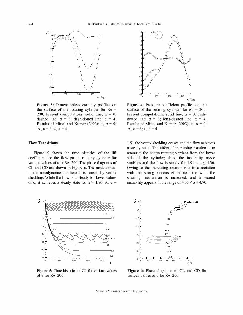
Flow Transitions
Figure 5 shows the time histories of the lift coefficient for the flow past a rotating cylinder for various values of α at Re=200. The phase diagrams of CL and CD are shown in Figure 6. The unsteadiness in the aerodynamic coefficients is caused by vortex shedding. While the flow is unsteady for lower values of α, it achieves a steady state for α > 1.90. At α =
1.91 the vortex shedding ceases and the flow achieves a steady state. The effect of increasing rotation is to attenuate the contra-rotating vortices from the lower side of the cylinder; thus, the instability mode vanishes and the flow is steady for 1.91 < α ≤ 4.30. Owing to the increasing rotation rate in association with the strong viscous effect near the wall, the shearing mechanism is increased, and a second instability appears in the range of 4.35 ≤ α ≤ 4.70.
0 50 100 150 200t
-35
-30
-25
-20
-15
-10
-5
0CL
00.5
1.01.51.9
2.5
3.0
3.5
4.0
4.35
4.50 4.70
5.5
5.0
6.0
-2 -1.5 -1 -0.5 0 0.5 1 1.5
CD
-35
-30
-25
-20
-15
-10
-5
0CL
0.51.0
1.51.9
2.02.5
3.5
4.0
3.0
4.30
4.35
4.50
4.704.75
5.0
5.5
6.0
α=0
-2 -1.5 -1 -0.5 0 0.5 1 1.5CD
-35
-30
-25
-20
-15
-10
-5
0CL
0.51.0
1.51.9
2.02.5
3.5
4.0
3.0
4.30
4.35
4.50
4.704.75
5.0
5.5
6.0
α=0α=0
Figure 5: Time histories of CL for various values of α for Re=200.
Figure 6: Phase diagrams of CL and CD for various values of α for Re=200.
Effect of Rotation Rates on the Laminar Flow and Heat Transfer Past a Circular Cylinder 525
Brazilian Journal of Chemical Engineering Vol. 32, No. 02, pp. 519 - 529, April - June, 2015
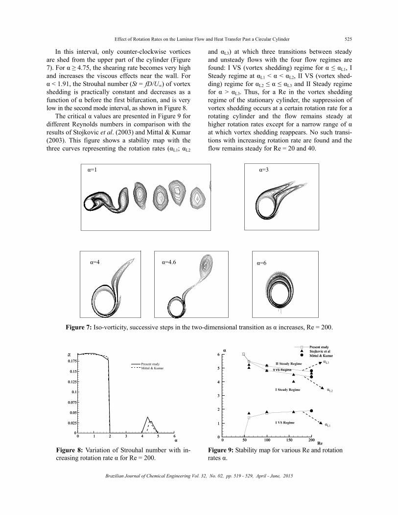
In this interval, only counter-clockwise vortices are shed from the upper part of the cylinder (Figure 7). For α ≥ 4.75, the shearing rate becomes very high and increases the viscous effects near the wall. For α < 1.91, the Strouhal number (St = fD/U∞) of vortex shedding is practically constant and decreases as a function of α before the first bifurcation, and is very low in the second mode interval, as shown in Figure 8.
The critical α values are presented in Figure 9 for different Reynolds numbers in comparison with the results of Stojkovic et al. (2003) and Mittal & Kumar (2003). This figure shows a stability map with the three curves representing the rotation rates (αL1; αL2
and αL3) at which three transitions between steady and unsteady flows with the four flow regimes are found: I VS (vortex shedding) regime for α ≤ αL1, I Steady regime at αL1 < α < αL2, II VS (vortex shed-ding) regime for αL2 ≤ α ≤ αL3 and II Steady regime for α > αL3. Thus, for a Re in the vortex shedding regime of the stationary cylinder, the suppression of vortex shedding occurs at a certain rotation rate for a rotating cylinder and the flow remains steady at higher rotation rates except for a narrow range of α at which vortex shedding reappears. No such transi-tions with increasing rotation rate are found and the flow remains steady for Re = 20 and 40.
α=3α=1
α=6α=4.6α=4
α=3α=1
α=6α=4.6α=4
α=3α=1
α=6α=4.6α=4
Figure 7: Iso-vorticity, successive steps in the two-dimensional transition as α increases, Re = 200.
0 1 2 3 4 5 60
0.025
0.05
0.075
0.1
0.125
0.15
0.175
St
Present studyMittal & Kumar
0.025
0000
0.075
00.05
0.125
000.1
0.175
00.15
1 2 3 4 5 60
St
α
Present studyMittal & Kumar
0 1 2 3 4 5 60
0.025
0.05
0.075
0.1
0.125
0.15
0.175
St
Present studyMittal & Kumar
0.025
0000
0.075
00.05
0.125
000.1
0.175
00.15
0.025
0000
0.075
00.05
0.125
000.1
0.175
00.15
1 2 3 4 5 60 1 2 3 4 5 60
St
α
Present studyMittal & Kumar
0 50 100 150 2000
1
2
3
4
5
6
Present stdyStojkovic et allMittal et Kumar
I VS Regime
I Steady Regime
II Steady RegimeII VS Regime
α
Re
αL2
αL3
αL1
4
3
6
5
0
2
1
0 50 100 150 200
Present study
Mittal & KumarStojkovic et al
II Steady Regime
I Steady Regime
I VS Regime
0 50 100 150 2000
1
2
3
4
5
6
Present stdyStojkovic et allMittal et Kumar
I VS Regime
I Steady Regime
II Steady RegimeII VS Regime
α
Re
αL2
αL3
αL1
4
3
6
5
0
2
1
4
3
6
5
0
2
1
4
3
6
5
0
2
1
0 50 100 150 2000 50 100 150 200
Present study
Mittal & KumarStojkovic et alPresent study
Mittal & KumarStojkovic et al
II Steady Regime
I Steady Regime
I VS Regime
Figure 8: Variation of Strouhal number with in-creasing rotation rate α for Re = 200.
Figure 9: Stability map for various Re and rotation rates α.
526 R. Bouakkaz, K. Talbi, M. Ouazzazi, Y. Khelili and F. Salhi
Brazilian Journal of Chemical Engineering
Isotherm Patterns
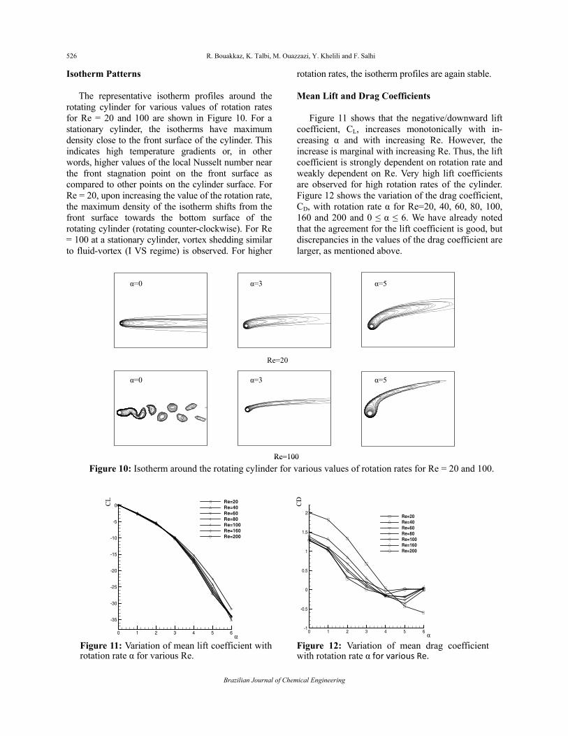
The representative isotherm profiles around the rotating cylinder for various values of rotation rates for Re = 20 and 100 are shown in Figure 10. For a stationary cylinder, the isotherms have maximum density close to the front surface of the cylinder. This indicates high temperature gradients or, in other words, higher values of the local Nusselt number near the front stagnation point on the front surface as compared to other points on the cylinder surface. For Re = 20, upon increasing the value of the rotation rate, the maximum density of the isotherm shifts from the front surface towards the bottom surface of the rotating cylinder (rotating counter-clockwise). For Re = 100 at a stationary cylinder, vortex shedding similar to fluid-vortex (I VS regime) is observed. For higher
rotation rates, the isotherm profiles are again stable. Mean Lift and Drag Coefficients
Figure 11 shows that the negative/downward lift coefficient, CL, increases monotonically with in-creasing α and with increasing Re. However, the increase is marginal with increasing Re. Thus, the lift coefficient is strongly dependent on rotation rate and weakly dependent on Re. Very high lift coefficients are observed for high rotation rates of the cylinder. Figure 12 shows the variation of the drag coefficient, CD, with rotation rate α for Re=20, 40, 60, 80, 100, 160 and 200 and 0 ≤ α ≤ 6. We have already noted that the agreement for the lift coefficient is good, but discrepancies in the values of the drag coefficient are larger, as mentioned above.
Re=20
Re=100
α=0 α=3 α=5
α=0 α=3 α=5
Re=20
Re=100
α=0 α=3 α=5
α=0 α=3 α=5
Figure 10: Isotherm around the rotating cylinder for various values of rotation rates for Re = 20 and 100.
0 1 2 3 4 5 6
-35
-30
-25
-20
-15
-10
-5
0Re=20Re=40Re=60Re=80Re=100Re=160Re=200
α
CL
0 1 2 3 4 5 6
-35
-30
-25
-20
-15
-10
-5
0Re=20Re=40Re=60Re=80Re=100Re=160Re=200
α
CL
0 1 2 3 4 5 6
V1
-1
-0.5
0
0.5
1
1.5
2
V2
Re=20Re=40Re=60Re=80Re=100Re=160Re=200
α
CD
α=0
0 1 2 3 4 5 6V1
-1
-0.5
0
0.5
1
1.5
2
V2
Re=20Re=40Re=60Re=80Re=100Re=160Re=200
α
CD
α=0
0 1 2 3 4 5 6V1
-1
-0.5
0
0.5
1
1.5
2
V2
Re=20Re=40Re=60Re=80Re=100Re=160Re=200
α
CD
α=0
Figure 11: Variation of mean lift coefficient with rotation rate α for various Re.
Figure 12: Variation of mean drag coefficient with rotation rate α for various Re.
Effect of Rotation Rates on the Laminar Flow and Heat Transfer Past a Circular Cylinder 527
Brazilian Journal of Chemical Engineering Vol. 32, No. 02, pp. 519 - 529, April - June, 2015
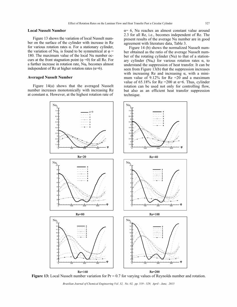
Local Nusselt Number
Figure 13 shows the variation of local Nusselt num-ber on the surface of the cylinder with increase in Re for various rotation rates α. For a stationary cylinder, the variation of NuL is found to be symmetrical at φ = 180. The maximum value of the local Nu number oc-curs at the front stagnation point (φ =0) for all Re. For a further increase in rotation rate, NuL becomes almost independent of Re at higher rotation rates (α=6). Averaged Nusselt Number
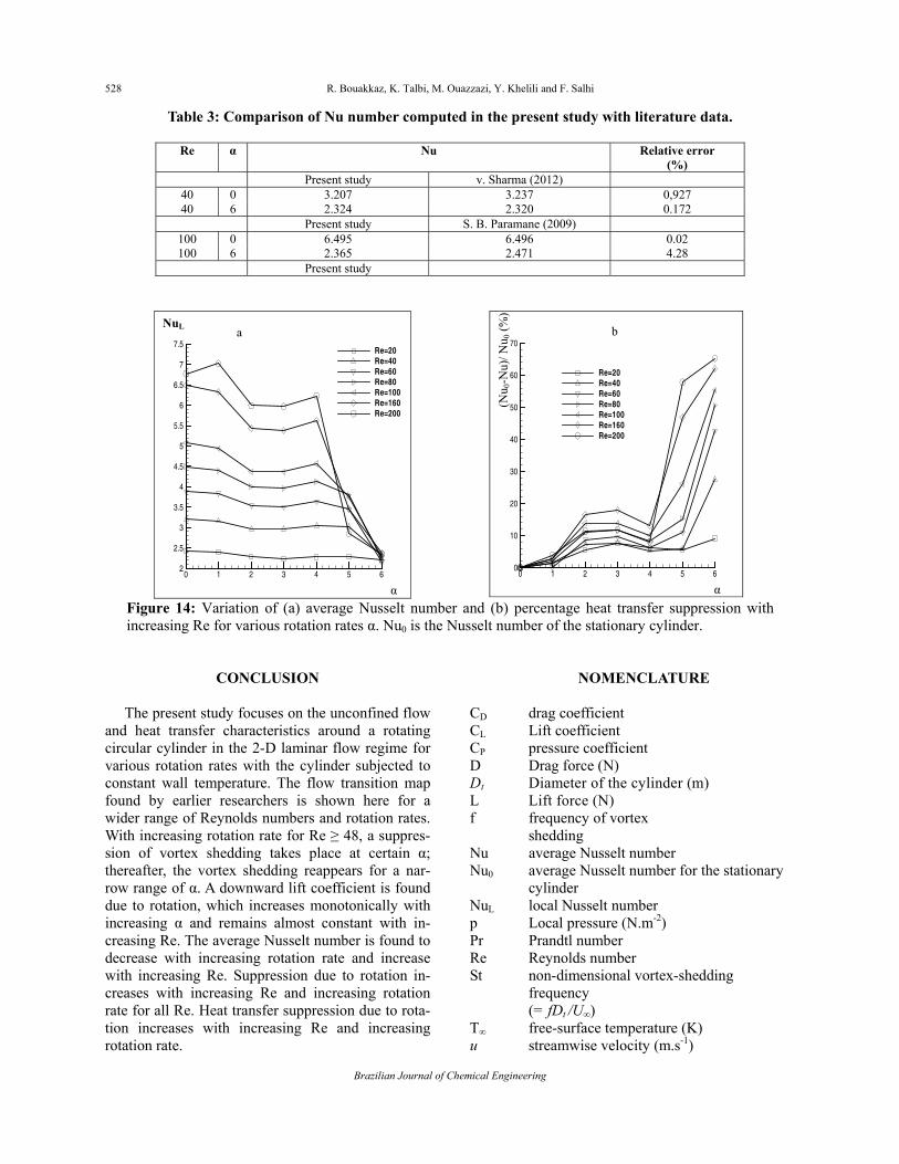
Figure 14(a) shows that the averaged Nusselt number increases monotonically with increasing Re at constant α. However, at the highest rotation rate of
α= 6, Nu reaches an almost constant value around 2.3 for all Re, i.e., becomes independent of Re. The present results of the average Nu number are in good agreement with literature data, Table 3.
Figure 14 (b) shows the normalized Nusselt num-ber obtained as the ratio of the average Nusselt num-ber of the rotating cylinder (Nu) to that of a station-ary cylinder (Nu0) for various rotation rates α, to understand the suppression of heat transfer. It can be seen from Figure 13(b) that the suppression increases with increasing Re and increasing α, with a mini-mum value of 9.12% for Re =20 and a maximum value of 65.18% for Re =200 at α=6. Thus, cylinder rotation can be used not only for controlling flow, but also as an efficient heat transfer suppression technique.
Re=160 Re=200
θ
Re=20
Re=20
0 100 200 3001
1.5
2
2.5
3
3.5
4
4.5
5
5.5
6
6.5
7
7.5
8
1
2
3
4
5
6
α=0
NuL
0 100 200 3001
2
3
4
5
6
7
8
9
10
11
12
13
0123456
NuL
0 100 200 3001
2
3
4
5
6
7
8
9
10
11
12
13
0123456
NuL
0 100 200 3001
2
3
4
5
6
7
8
9
10
0123456
NuL
Re=40
Re=80 Re=100
0 100 200 3001
2
3
4
5
6
7
8
9
100
1
2
3
4
5
6
0 100 200 3001
1.5
2
2.5
3
3.5
4
4.5
5
5.5
6
6.5
7
7.5
8
0
1
2
3
4
5
6
NuL
NuL
φ
φ
φ
φ
φ
φ
φ
φ
φ
φ
φ
φ
Figure 13: Local Nusselt number variation for Pr = 0.7 for varying values of Reynolds number and rotation.
528 R. Bouakkaz, K. Talbi, M. Ouazzazi, Y. Khelili and F. Salhi
Brazilian Journal of Chemical Engineering
Table 3: Comparison of Nu number computed in the present study with literature data.
Re α Nu Relative error (%)
Present study v. Sharma (2012) 40 0 3.207 3.237 0,927 40 6 2.324 2.320 0.172
Present study S. B. Paramane (2009) 100 0 6.495 6.496 0.02 100 6 2.365 2.471 4.28
Present study
0 1 2 3 4 5 62
2.5
3
3.5
4
4.5
5
5.5
6
6.5
7
7.5Re=20Re=40Re=60Re=80Re=100Re=160Re=200
a
α
NuL
0 1 2 3 4 5 6
0
10
20
30
40
50
60
70
Re=20Re=40Re=60Re=80Re=100Re=160Re=200
α
b
(Nu 0
-Nu)
/ Nu 0
(%)
Figure 14: Variation of (a) average Nusselt number and (b) percentage heat transfer suppression with increasing Re for various rotation rates α. Nu0 is the Nusselt number of the stationary cylinder.
CONCLUSION
The present study focuses on the unconfined flow and heat transfer characteristics around a rotating circular cylinder in the 2-D laminar flow regime for various rotation rates with the cylinder subjected to constant wall temperature. The flow transition map found by earlier researchers is shown here for a wider range of Reynolds numbers and rotation rates. With increasing rotation rate for Re ≥ 48, a suppres-sion of vortex shedding takes place at certain α; thereafter, the vortex shedding reappears for a nar-row range of α. A downward lift coefficient is found due to rotation, which increases monotonically with increasing α and remains almost constant with in-creasing Re. The average Nusselt number is found to decrease with increasing rotation rate and increase with increasing Re. Suppression due to rotation in-creases with increasing Re and increasing rotation rate for all Re. Heat transfer suppression due to rota-tion increases with increasing Re and increasing rotation rate.
NOMENCLATURE CD drag coefficient CL Lift coefficient CP pressure coefficient D Drag force (N) Dt Diameter of the cylinder (m) L Lift force (N) f frequency of vortex
shedding Nu average Nusselt number Nu0 average Nusselt number for the stationary
cylinder NuL local Nusselt number p Local pressure (N.m-2) Pr Prandtl number Re Reynolds number St non-dimensional vortex-shedding
frequency (= fDt /U∞)
T∞ free-surface temperature (K) u streamwise velocity (m.s-1)
Effect of Rotation Rates on the Laminar Flow and Heat Transfer Past a Circular Cylinder 529
Brazilian Journal of Chemical Engineering Vol. 32, No. 02, pp. 519 - 529, April - June, 2015
U∞ free-stream velocity (m.s-1) U non-dimensional streamwise velocity
(= u/U∞) v cross-stream velocity (m.s-1) V non-dimensional cross-stream velocity
(= v/ U∞)) x streamwise dimension of coordinates, m X non-dimensional streamwise dimension of
coordinates (=x/D) y cross-stream dimension of coordinates, m Y non-dimensional cross-stream dimension
of coordinates (=y/Dt) Greek Symbols α non-dimensional rotation rate
(=ΩD/2U∞) φ angular displacement from the front
stagnation point (degree) τ non-dimensional time θ non-dimensional temperature ω vorticity on the surface of the cylinder (s-1)ϖ Dimensionless vorticity on the surface of
the cylinder (=2ωDt/U∞) Ω constant angular velocity of the cylinder
rotation (rads-1)
REFERENCES Badr, H. M., Dennis, S. C. R., Young, P. J. S., Steady
and unsteady flow past a rotating circular cy-linder at low Reynolds numbers. Comput. Fluids, 17(4), pp. 579-609 (1989).
Dol, S. S., Kopp, G. A. and Martinuzzi, R. J., The suppression of periodic vortex shedding from a rotating cylinder. Journal of Wind Engineering and Industrial Aerodynamics, 96, pp. 1164-1184 (2008)
El Akoury, R., Braza, M., Perrin, R., Harran, G. and Horau, Y., The three-dimensional transition in the flow around a rotating cylinder. J. Fluid Mech., 607, pp. 1-11 (2008).
Hasan, N., Mousa, F., Kurosh, S. and Ehsan, F.,
Multi-relaxation-time lattice Boltzman model for uniform-shear flow over a rotating circular cylin-der. Thermal Science, 15(3), pp. 859-878 (2010).
Hu, G., Sun, D., Yin, X. and Tong, B., Hopf bifurca-tion in wakes behind a rotating and translating circular cylinder. Phys. Fluids, 8 (1996).
Ingham, D. B. and Tang, T., A numerical investiga-tion into the steady flow past a rotating circular cylinder at low and intermediate Reynolds num-bers. J. Comput. Phys., 87, pp. 91-107 (1990).
Kang, S., Choi, H. and Lee, S., Laminar flow past a rotating circular cylinder. Phys. Fluids, 11, pp. 3312-3321 (1999).
Lam, K. M., Vortex shedding flow behind a slowly rotating circular cylinder. J. Fluids. Struct., 25(2), pp. 245-262 (2009).
Mittal, S. and Kumar, B., Flow past a rotating cylin-der. J. Fluid Mech., 476, pp. 303-334 (2003).
Morgan, V. T., The overall convective heat transfer from smooth circular cylinders. Adv. Heat Transfer, 11, pp. 199-264 (1975).
Nobari, M. R. H., Ghazanfarian, J., Convective heat transfer from a rotating cylinder with inline oscil-lation. Int. J. Thermal Sciences, 49(10), pp. 2026-2036 (2010).
Paramane, S. B., Sharma, A., Heat and Fluid flow across a rotating cylinder dissipating uniform heat flux in 2D laminar flow regime. Int. J. Heat Mass Transf., 53, pp. 4672-4683 (2010)
Paramane, S. B., Sharma, A., Numerical investiga-tion of heat and fluid flow across a rotating circu-lar cylinder maintained at constant temperature in 2-D laminar flow regime. Int. J. Heat and Mass Transf., 52, pp. 3205-3216 (2009).
Sharma, V. and Dhiman, A. K., Heat transfer from a rotating circular cylinder in the steady regime. Thermal Sciences, 16(1), pp. 79-91 (2012).
Stojkovic, D., Schon, P., Breuer, M. and Durst, F., On the new vortex shedding mode past a rotating circular. Phys. Fluids, 15(5), pp. 1257-1260 (2003).
Yan, Y. Y., Zu, Y. Q., Numerical simulation of heat transfer and fluid flow past a rotating isothermal cylinder – a LBM approach. Int. J. Heat Mass Transf., 51, pp. 2519-2536 (2008).