Environmental Impact Assessment for TASNEE Petrochemicals Ethylene and Polyethylene Projects TASNEE Petrochemicals Al-Jubail Saudi Arabia This document contains proprietary information belonging to Fluor B.V., its parent and/or affiliated companies and shall be used only for the purpose for which it was supplied. It shall not be copied, reproduced or otherwise used, nor shall such information be furnished in whole or in part to others, except in accordance with the terms of any agreement under which it was supplied or with the prior written consent of Fluor B.V. and shall be returned upon request. Client 0 23-Dec-05 First issue MJ GZ MU ISSUE DATE DESCRIPTION BY CHK'D APP'D SHEET DOC. NO. 1 of 62 185923-E-EIA-001 ®
Transcript
Environmental Impact Assessment for
TASNEE Petrochemicals Ethylene and Polyethylene Projects
TASNEE Petrochemicals Al-Jubail
Saudi Arabia
This document contains proprietary information belonging to Fluor B.V., its parent and/or affiliated companies and shall be used only for the purpose for which it was supplied. It shall not be copied, reproduced or otherwise used, nor shall such information be furnished in whole or in part to others, except in accordance with the terms of any agreement under which it was supplied or with the prior written consent of Fluor B.V. and shall be returned upon request.
Client
0 23-Dec-05 First issue MJ GZ MU
ISSUE DATE DESCRIPTION BY CHK'D APP'D
SHEET
DOC. NO.
1 of 62 185923-E-EIA-001
®
TASNEE Petrochemicals Environmental Impact Assessment Ethylene and Polyethylene Projects Doc. No. 185923-E-EIA-001 Al-Jubail, Saudi Arabia December 2005
Page 2 of 62 ®
TABLE OF CONTENTS
0 EXECUTIVE SUMMARY.........................................................................................5 0.1 Introduction ............................................................................................................................. 5 0.2 Project overview ..................................................................................................................... 6 0.3 Regulatory framework ............................................................................................................ 6 0.4 Environmental and social impacts.......................................................................................... 7 0.5 Analysis of alternatives........................................................................................................... 9 0.6 Environmental management plan......................................................................................... 10 0.7 General assessment of the project....................................................................................... 10
1 INTRODUCTION AND PROJECT OVERVIEW ....................................................12 1.1 The need for project implementation.................................................................................... 12 1.2 General project outline ......................................................................................................... 13 1.3 Scope of the Environmental Impact Assessment................................................................. 13 1.4 Brief project description ........................................................................................................ 15 1.4.1 Ethylene plant ....................................................................................................................... 15 1.4.2 Polyethylene plant ................................................................................................................ 15 1.5 Abbreviations / Acronyms used ............................................................................................ 16
2 REGULATORY FRAMEWORK ............................................................................18 2.1 World Bank Standards.......................................................................................................... 18 2.2 Kingdom of Saudi Arabia Standards .................................................................................... 18 2.3 Comparison of World Bank vs. KSA standards.................................................................... 19
TASNEE Petrochemicals Environmental Impact Assessment Ethylene and Polyethylene Projects Doc. No. 185923-E-EIA-001 Al-Jubail, Saudi Arabia December 2005
Page 3 of 62 ®
3.3.4 Hot water system .................................................................................................................. 28 3.3.5 Regenerative thermal oxidizer .............................................................................................. 28 3.4 Feedstock and product profile .............................................................................................. 28 3.5 Energy requirements ............................................................................................................ 29
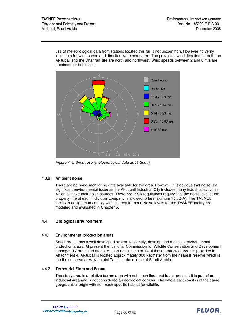
4 BASELINE ENVIRONMENTAL AND SOCIAL CONDITIONS .............................30 4.1 Environmental Baseline Study.............................................................................................. 30 4.2 Socio-economic environment ............................................................................................... 30 4.2.1 Demography ......................................................................................................................... 30 4.2.2 Economic activity .................................................................................................................. 31 4.2.3 Employment characteristics.................................................................................................. 31 4.2.4 Sensitive structures .............................................................................................................. 31 4.2.5 Infrastructure......................................................................................................................... 32 4.3 Physical environment ........................................................................................................... 33 4.3.1 Terrain and topography ........................................................................................................ 33 4.3.2 Land use and land cover ...................................................................................................... 33 4.3.3 Climate and meteorology...................................................................................................... 34 4.3.4 Water quality and use ........................................................................................................... 34 4.3.5 Geology................................................................................................................................. 35 4.3.6 Hydrology and drainage pattern ........................................................................................... 36 4.3.7 Air Quality ............................................................................................................................. 37 4.3.8 Ambient noise ....................................................................................................................... 38 4.4 Biological environment ......................................................................................................... 38 4.4.1 Environmental protection areas............................................................................................ 38 4.4.2 Terrestrial Flora and Fauna .................................................................................................. 38 4.4.3 Marine ecosystems............................................................................................................... 39 4.4.4 Endangered and threatened species.................................................................................... 39 4.5 Overall environmental and social baseline assessment ...................................................... 39
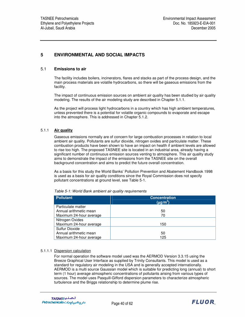
5 ENVIRONMENTAL AND SOCIAL IMPACTS.......................................................40 5.1 Emissions to air .................................................................................................................... 40 5.1.1 Air quality .............................................................................................................................. 40 5.1.2 Volatile organic compounds.................................................................................................. 49 5.2 Emissions to water ............................................................................................................... 49 5.3 Solid and hazardous wastes................................................................................................. 49 5.4 Ambient noise ....................................................................................................................... 50 5.4.1 Introduction ........................................................................................................................... 50 5.4.2 Technical Evaluation............................................................................................................. 50 5.4.3 Results .................................................................................................................................. 52 5.4.4 Conclusions .......................................................................................................................... 53 5.5 External safety...................................................................................................................... 54 5.6 Visual impact ........................................................................................................................ 54 5.7 Social impacts....................................................................................................................... 54
6 ANALYSIS OF ALTERNATIVES..........................................................................55
7 ENVIRONMENTAL MANAGEMENT PLAN .........................................................57 7.1 Construction & Commissioning ............................................................................................ 57 7.1.1 Air quality monitoring ............................................................................................................ 57 7.1.2 Noise Monitoring................................................................................................................... 57 7.1.3 Monitoring of Water discharged to Royal Commission waste water treatment facilities...... 57 7.1.4 Waste.................................................................................................................................... 57
TASNEE Petrochemicals Environmental Impact Assessment Ethylene and Polyethylene Projects Doc. No. 185923-E-EIA-001 Al-Jubail, Saudi Arabia December 2005
Page 4 of 62 ®
7.2 Operational Phase................................................................................................................ 58 7.2.1 Air and Emissions Monitoring ............................................................................................... 58 7.2.2 VOCs .................................................................................................................................... 58 7.2.3 Noise Monitoring................................................................................................................... 58 7.2.4 Land Quality Monitoring........................................................................................................ 58 7.2.5 Water and Wastewater Monitoring ....................................................................................... 58
8 GENERAL ASSESSMENT OF THE PROJECT ...................................................59
TASNEE Petrochemicals Environmental Impact Assessment Ethylene and Polyethylene Projects Doc. No. 185923-E-EIA-001 Al-Jubail, Saudi Arabia December 2005
Page 5 of 62 ®
0 EXECUTIVE SUMMARY
0.1 Introduction
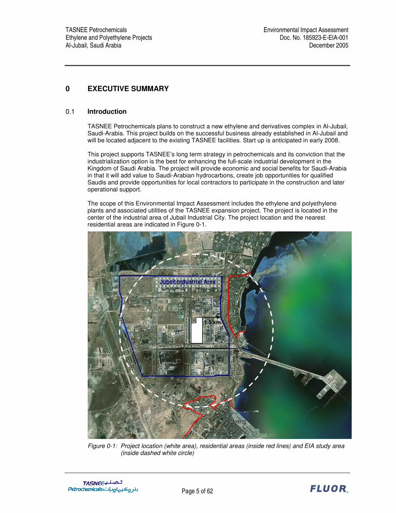
TASNEE Petrochemicals plans to construct a new ethylene and derivatives complex in Al-Jubail, Saudi-Arabia. This project builds on the successful business already established in Al-Jubail and will be located adjacent to the existing TASNEE facilities. Start up is anticipated in early 2008. This project supports TASNEE’s long term strategy in petrochemicals and its conviction that the industrialization option is the best for enhancing the full-scale industrial development in the Kingdom of Saudi Arabia. The project will provide economic and social benefits for Saudi-Arabia in that it will add value to Saudi-Arabian hydrocarbons, create job opportunities for qualified Saudis and provide opportunities for local contractors to participate in the construction and later operational support. The scope of this Environmental Impact Assessment includes the ethylene and polyethylene plants and associated utilities of the TASNEE expansion project. The project is located in the center of the industrial area of Jubail Industrial City. The project location and the nearest residential areas are indicated in Figure 0-1.
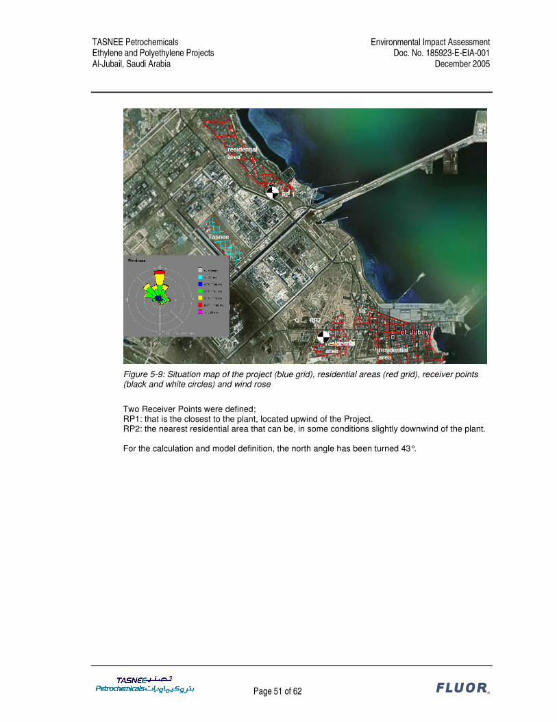
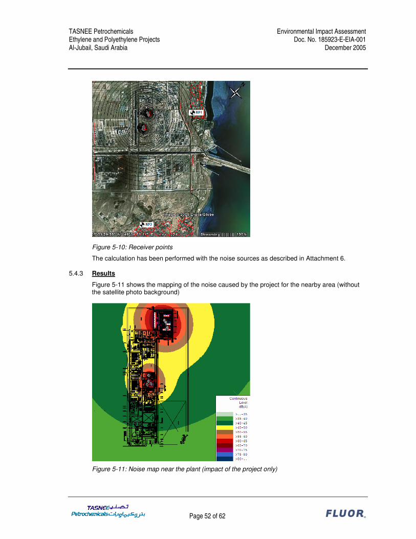
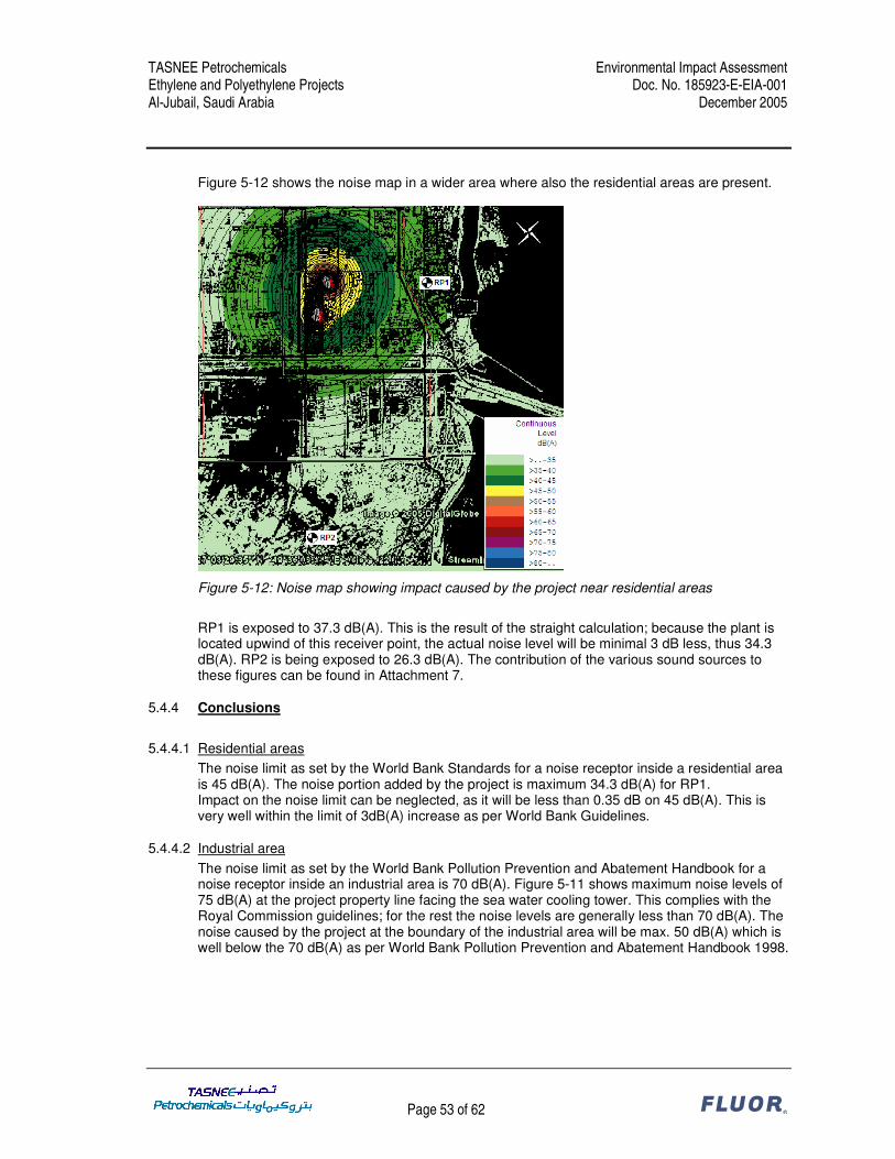
Figure 0-1: Project location (white area), residential areas (inside red lines) and EIA study area (inside dashed white circle)
1.5 km
Jubail Industrial Area
TASNEE Petrochemicals Environmental Impact Assessment Ethylene and Polyethylene Projects Doc. No. 185923-E-EIA-001 Al-Jubail, Saudi Arabia December 2005
Page 6 of 62 ®
0.2 Project overview
The project consists of an ethylene plant, a HDPE plant and a LDPE plant. The ethylene plant produces 1,000,000 t/a of polymer grade ethylene and about 280,000 t/a of polymer grade propylene from the ethane and propane feedstock. The HDPE plant produces 400,000 t/a of HDPE pellets and the LDPE plant produces 400,000 t/a of LDPE pellets. The ethylene plant is based on thermal cracking of petroleum hydrocarbons with steam, so called pyrolysis or steam cracking. The plant uses a feedstock from Aramco consisting of 55 MM SCFD of ethane and 40,000 BBL/day of propane. The mixed C4 byproduct produced shall be hydrogenated and cracked to extinction. Pyrolysis gasoline which is one of the byproducts produced will be transported for sale by pipeline to a third party. A PSA type hydrogen purification system for the production of high purity hydrogen is included for acetylene conversion as well as export to the Polyethylene unit. The ethylene unit also includes a spent caustic treatment facility and a waste oil incinerator. The HDPE unit utilizes Basell’s Hostalen ACP (Advanced Cascade Process) technology. For the ACP process catalyst is supplied by an external party and unloaded into catalyst storage vessels which feed the polymerization reactor through a catalyst dosing device after further dilution with hexane. Reactor feed comprising of ethylene, co-monomer & hydrogen is continuously fed to 3 reactors operated in series for multimodal production. Hexane solvent is pumped to the reactor. Hexane is recovered downstream from the powder product and recycled back to the reactors. Co-catalyst is added to the recycle hexane stream. Polymerization occurs at a pressure of 5 to 10 bar and at a temperature of 75 - 90°C. The heat of reaction is removed with cooling water. The polymer slurry flows out of the reactor and the powder and the mother liquor are separated initially in a centrifuge and later on by using fluidized bed dryers. The powder is then sent to the extruder for pelletizing. In order to manufacture colored grades a dedicated extruder sized for plant design capacity with necessary downstream equipment is also presently envisaged. The LDPE Unit utilizes Basell’s Lupotec technology. Basell’s Lupotec technology utilizes a tubular reactor for the production of LDPE. The process essentially involves pressurizing ethylene to 2600-3100 bar and feeding a tubular reactor which typically has an internal diameter of 1.2-3.2 inches and is 1500-2000 meters in length depending on the plant capacity. Peroxide as initiator is directly fed to the reactor. The feed temperature is raised to 130-180 °C to start the strongly exothermic reaction and cooling is used to prevent the reactants from exceeding 330 °C. Hot water is used in tube jackets generating medium pressure & low pressure steam. Per pass conversion of 25 to 35% is achieved based on grade. To improve heat transfer high gas velocities are used and depending upon the grade the reactor pressure control valve at the end of the reactor is operated in either “kicking” or “non-kicking” mode. The reactor pressure control valve discharges the LDPE/ethylene mixture into a high pressure separator. In the separator most of the ethylene is removed and recycled. The polymer melt is further depressurized to 1 bar in the low pressure product separator. The melt is then sent to the extruder for pelletizing and further degassing.
0.3 Regulatory framework
The World Bank Group’s “Pollution Prevention and Abatement Handbook” (Handbook, ref. 1) effective July 1998 contains the relevant WB standards. The Handbook consists of three major sections. The first deals with an overview of key policy lessons in pollution management. The second contains guidelines mainly meant for local government policy makers on establishing a sound environmental policy. The third part contains the Project Guidelines. In assessing the environmental impacts of the project, the environmental standards from the Project Guidelines on Petrochemical Manufacturing have been followed.
TASNEE Petrochemicals Environmental Impact Assessment Ethylene and Polyethylene Projects Doc. No. 185923-E-EIA-001 Al-Jubail, Saudi Arabia December 2005
Page 7 of 62 ®
The relevant standards from the local authorities are contained in the “Royal Commission Environmental Regulations 2004” (RCER, ref. 2). The RCER have been compiled by the Environmental Control Department of the Royal Commission for Jubail and Yanbu Industrial Cities. The RCER consists of two volumes. Volume 1 provides an overview of the environmental regulatory system and lists the standards and regulations. Volume 2 outlines the requirements for the environmental permit package and contains the forms to be used for the permit application. All new industrial facilities are required to join the RC’s Consolidated Permit Program. This program governs all procedures associated with obtaining the necessary Environmental Consent to Construct (ECC) and Environmental Permit to Operate (EPO). The operator shall obtain an ECC from the RC before starting construction of a new facility. The operator of a new facility shall not operate it or carry out process commissioning without a valid EPO issued by the RC. The RCER contain environmental standards on emissions to air, emissions to water, hazardous materials management, waste management, dredging, noise, and reporting and record keeping. For the TASNEE Petrochemicals Ethylene and Polyethylene Projects an Environmental Information Report (ref. 3-5) has been prepared to demonstrate compliance of the design with the KSA standards and to apply for an Environmental Consent to Construct and an Environmental Permit to Operate. The relevant standards of the WB and the KSA have been reviewed and these have been compared to the design of the TASNEE Petrochemicals Ethylene and Polyethylene projects. The results of the review of the environmental standards and how these standards are incorporated into the design of the project are documented in three Environmental Compliance Reports, which are included as Attachment 1, 2 and 3.
0.4 Environmental and social impacts
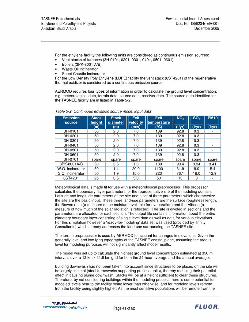
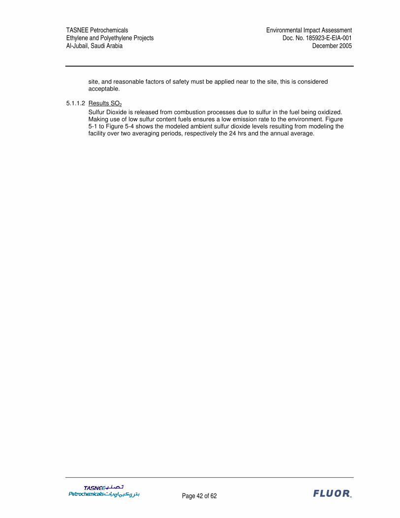
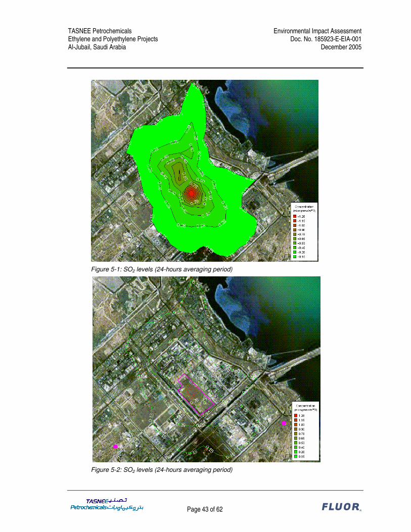
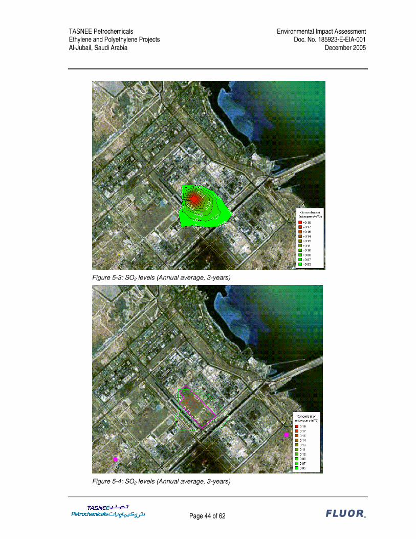
The Environmental Impact Assessment has addressed the significant issues relating to the potential environmental and social impacts of the TASNEE project. Air quality Gaseous emissions normally are of concern for large combustion processes in relation to local ambient air quality. Pollutants are sulfur dioxide, nitrogen oxides and particulate matter. These combustion products have been shown to have an impact on health if ambient levels are allowed to rise too high. For normal operation the software model used was the AERMOD Version 3.3.15 using the Breeze Graphical User Interface as supplied by Trinity Consultants. This model is used as a standard for regulatory air modeling in the USA and is generally accepted internationally. For the ethylene facility the following units are considered as continuous emission sources: • Vent stacks of furnaces (3H-0101, 0201, 0301, 0401, 0501, 0601) • Boilers (3PK-8001 A/B) • Waste Oil Incinerator • Spent Caustic Incinerator For the Low Density Poly Ethylene (LDPE) facility the vent stack (6ST4201) of the regenerative thermal oxidizer is considered as a continuous emission source.
TASNEE Petrochemicals Environmental Impact Assessment Ethylene and Polyethylene Projects Doc. No. 185923-E-EIA-001 Al-Jubail, Saudi Arabia December 2005
Page 8 of 62 ®
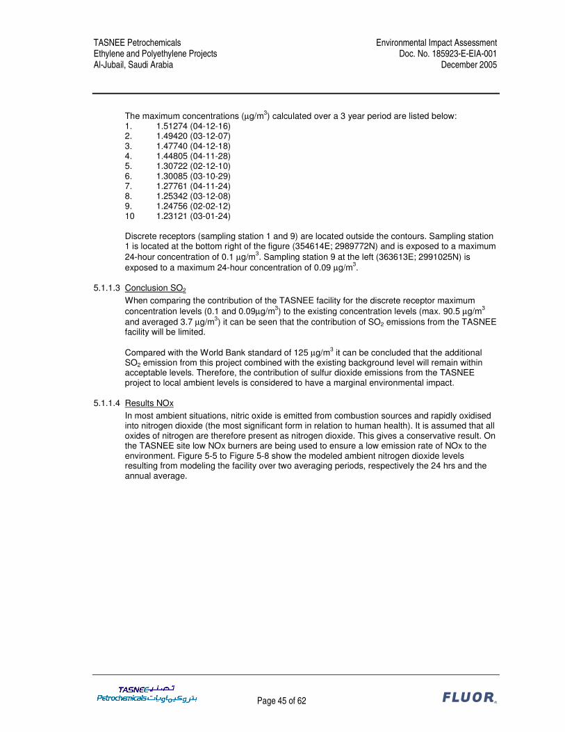
For SOx the maximum 24-hour averaged contribution of the TASNEE facility at the receptor location amounts to 0.1 µg/m3. Compared to the average existing background concentration level of 3.7 µg/m3 and the World Bank standard of 125 µg/m3 it is concluded that the TASNEE facility has a marginal impact on the ambient SOx levels and that the total level will remain within acceptable levels. For NOx the maximum 24-hour averaged contribution of the TASNEE facility at the receptor location amounts to 3.0 µg/m3. Compared to the average existing background concentration level of 28.2 µg/m3 and the World Bank standard of 150 µg/m3 it is concluded that the TASNEE facility has a marginal impact on the ambient NOx levels and that the total level will remain within acceptable levels. For PM10 the maximum 24-hour averaged contribution of the TASNEE facility at the receptor location amounts to 0.1 µg/m3. Insufficient background data is available to evaluate the impact on the total ambient concentration level. Compared to the World Bank standard of 70 µg/m3 the impact of the additional PM10 emission from this project will be limited. The PM10 emissions of the waste oil incinerator and the spent caustic incinerator are designed to comply with the Royal Commission environmental standards. However, the World Bank emission limit for incinerator stacks is more stringent than the RCER. Since it was concluded that the impact of the additional PM10 emission from this project will be limited, it follows that both incinerators have an acceptable emission level and a marginal environmental impact. Volatile organic compounds Within the Ethylene and Polyethylene projects continuous emissions of volatile organic compounds (VOC) do not occur. The only emissions of VOC’s are fugitive emissions arising from leakage of valves, flanges or other equipment. In the design fugitive emissions are prevented, e.g. by using double mechanical seals for pumps in VOC and HAP service. According to the RCER all equipment in VOC or organic HAP service has to be included in a Leak Detection And Repair (LDAR) programme. Emissions to water Direct discharges to surface water do not occur for this facility. Wastewater is either sent to the Royal Commission Industrial Wastewater Treatment Plant or to the Royal Commission Sanitary Wastewater Treatment Plant. Storm water will be sent to the Royal Commission storm water drainage system. The wastewater effluent of the facility will be pre-treated to ensure compliance to the Royal Commission criteria for discharge to their water treatment facilities. Solid and hazardous wastes Solid wastes produced in the facility are mainly spent catalyst and waste from packaging materials or maintenance activities. The spent catalyst will be returned to the vendor for recycling when practicable or will be sent to a licensed disposal facility otherwise. A waste oil incinerator is part of this project to combust hazardous organic wastes. This is considered an effective treatment technology for petrochemical organic wastes. Ambient noise The noise level of the TASNEE project at the nearest residential receptor is calculated to be 34.3 dB(A). Compared to the World Bank standard for residential areas of 45 dB(A) during the nighttime the impact of the noise level of the TASNEE facility can be neglected as it will be 0.35 dB(A) on 45 dB(A). Compared to the World Bank limit of maximum 3 dB(A) increase for any project, it can be concluded that the noise level of the TASNEE facility has a marginal impact.
TASNEE Petrochemicals Environmental Impact Assessment Ethylene and Polyethylene Projects Doc. No. 185923-E-EIA-001 Al-Jubail, Saudi Arabia December 2005
Page 9 of 62 ®
The noise level of the TASNEE project at the boundary of the industrial area is calculated to be 50 dB(A). This is well below the World Bank guideline of 70 dB(A) for industrial areas which confirms the conclusion that the noise level of the TASNEE facility has a marginal impact. External safety The risk due to loss of containment in the Ethylene and Polyethylene plants will generally be contained within the fence. Only in case of large leaks of ethane/propane or ethylene, mainly in the ethylene plant, jet fires or explosions could cause damage to neighboring facilities. In view of the fact that the nearest residential area is located more than 2 kilometer away, hazardous effects for residential areas will be negligible. Within the design phase of this project various safety studies have been conducted to identify potential hazards and implement effective preventive and mitigation measures, such as Emergency Shutdown and Depressurization (ESD) systems, fire fighting systems and fire & gas detection systems. Visual impact The project is developed within an industrial zone. Within the project a flare stack of 150 meters height is foreseen. This will be visible in the skyline of the industrial zone. The nearest residential areas are more than 2 kilometer away from the proposed flare stack. Its impact is assessed to be of minor importance. Social impacts The social impact of the TASNEE project during construction of the facility is related to a temporary demand for housing facilities, local trades and local workforce and will create additional utilization of local infrastructure. As the city was developed as a center for industrial activity it has a well developed infrastructure and well developed local workforce. Therefore, the impact of constructing the facility will be limited. Once the facility has been built it will create an opportunity for extra employment. This will have a minor positive impact on the local economy.
0.5 Analysis of alternatives
There are a number of different technologies available for all three types of plants i.e. Ethylene plant, LDPE plant and HDPE plant. Although there are differences in each technology, e.g. type of reactor or number of reactors, they all employ the same type of operations within enclosed systems. From an environmental perspective all available technologies have similar environmental issues. For Steam Crackers for ethylene production the main environmental issues are: � Flue gases from furnaces and boilers � Spent Caustic For LDPE and HDPE plants the main environmental issues are: � Degassing of polyethylene pellets � Decomposition reactions in LDPE tubular reactor For these environmental aspects specific measures are implemented in the design, e.g. low NOx burners and low sulfur fuels, a spent caustic incinerator with Air Pollution Control system, a regenerative thermal oxidizer to treat the pellets purge gas and sophisticated reactor temperature control.
TASNEE Petrochemicals Environmental Impact Assessment Ethylene and Polyethylene Projects Doc. No. 185923-E-EIA-001 Al-Jubail, Saudi Arabia December 2005
Page 10 of 62 ®
0.6 Environmental management plan
Based on the Environmental Impact Assessment the following monitoring is envisaged to be executed to demonstrate that the TASNEE project is operated in compliance with KSA regulations and World Bank standards. During construction and commissioning: • Air quality monitoring; • Noise monitoring; • Monitoring of waste water that will be discharged to the Royal Commission WWTP; • Wastes leaving the site. Monitoring during the operational phase will be in accordance with KSA regulations and will include: • Air emissions monitoring for continuous sources; • VOCs monitoring; • Noise monitoring; • Waste water monitoring.
0.7 General assessment of the project
TASNEE Petrochemicals intends to expand their existing propylene and polypropylene petrochemical complex with an ethylene and polyethylene plant. The production of ethylene and polyethylene from finite, non-renewable resources implies that this expansion project will never be sustainable in absolute terms. However, numerous actions have been taken during project development to prevent negative impacts on the environment or the local community and any remaining negative impacts are minimized wherever practicable. This Environmental Impact Assessment has addressed the significant issues relating to the potential environmental and social impacts of the TASNEE project. The main findings on the potential project impacts are: • The project is located in the center of the industrial area of Jubail Industrial City. The area
has been developed as an industrial city in the 1980s and before that time the land was an uninhabited desert coastline. Significant cultural heritage or biological ecosystems are therefore not present at the project location nor can they be impacted by the TASNEE project. Therefore it is concluded that the main environmental issues relate to the impact of gaseous emissions from the TASNEE facilities on ambient air quality and to the impact of the noise levels generated by the process equipment;
• Gaseous emissions from large combustion processes contain the pollutants SOx, NOx and PM10. The impact of these emissions on the ambient air quality at the nearest residential areas has been studied and evaluated based on air quality modeling. Gaseous emissions are carefully controlled and the TASNEE facility will have a marginal impact on the ambient air quality;
• The assessment of the noise levels of the TASNEE project at the nearest residential receptor and at the boundary of the industrial area has shown that the noise level of the TASNEE facility has a marginal impact;
• The social impact of the TASNEE project during construction of the facility is related to a temporary demand for housing facilities, local trades and local workforce and will create additional utilization of local infrastructure. As the city was developed as a center for industrial activity it has a well developed infrastructure and well developed local workforce.
TASNEE Petrochemicals Environmental Impact Assessment Ethylene and Polyethylene Projects Doc. No. 185923-E-EIA-001 Al-Jubail, Saudi Arabia December 2005
Page 11 of 62 ®
Therefore, the impact of the construction of the facility will be limited. Once the facility has been built it will create an opportunity for extra employment. This will have a minor positive impact on the local economy.
This Environmental Impact Assessment shows that the potential environmental and social impacts of the TASNEE project have been taken into consideration during the development of this project. The project has been designed to prevent or reduce potential impacts and is subsequently designed to maximize the overall project sustainability.
TASNEE Petrochemicals Environmental Impact Assessment Ethylene and Polyethylene Projects Doc. No. 185923-E-EIA-001 Al-Jubail, Saudi Arabia December 2005
Page 12 of 62 ®
1 INTRODUCTION AND PROJECT OVERVIEW
1.1 The need for project implementation
TASNEE Petrochemicals also known as National Industrialization Company is a Saudi-Arabian holding company wholly owned by the private sector. From the very beginning TASNEE was guided by its absolute conviction that the industrialization option is the best for realizing diversification of the economic foundation and enhancing the full-scale industrial development in the Kingdom of Saudi Arabia. TASNEE’s vision is formulated as follows: A LEADING NATIONAL & REGIONAL INDUSTRIAL COMPANY IN ITS SPECIALIZED FIELDS, CARING FOR THE ENVIRONMENT AND QUALITY IN ITS PRODUCTS AND OPERATIONS, AND KEEN ON ITS RESPONSIBILITES TOWARD THE SHAREHOLDERS, CUSTOMERS, EMPLOYEES AND SOCIETY AT LARGE. In line with its vision TASNEE plans to construct a new ethylene and derivatives complex in Al-Jubail, Saudi-Arabia. This project builds on the successful business already established in Al-Jubail and will be located adjacent to the existing TASNEE facilities. Design work is underway and the start up is anticipated in early 2008. In doing so, it supports TASNEE’s long term strategy in petrochemicals. The project will provide economic and social benefits for Saudi-Arabia in that it will add value to Saudi-Arabian hydrocarbons, create job opportunities for qualified Saudis and provide opportunities for local contractors to participate in the construction and later operational support. The project location is ideally suited to maximize benefits of existing infrastructure within the Al-Jubail Industrial Complex and Port facilities. Furthermore, the location and the product plan of the project provides an excellent ability to integrate utilities, feedstock, fuel gas needs, and by-product synergies that allow optimization of natural resources and minimization of waste generation. The products will be supplied to markets in Asia, the Middle East, Africa and Europe to serve the rapidly expanding global demand for value-added plastics and chemicals of the highest quality.
TASNEE Petrochemicals Environmental Impact Assessment Ethylene and Polyethylene Projects Doc. No. 185923-E-EIA-001 Al-Jubail, Saudi Arabia December 2005
Page 13 of 62 ®
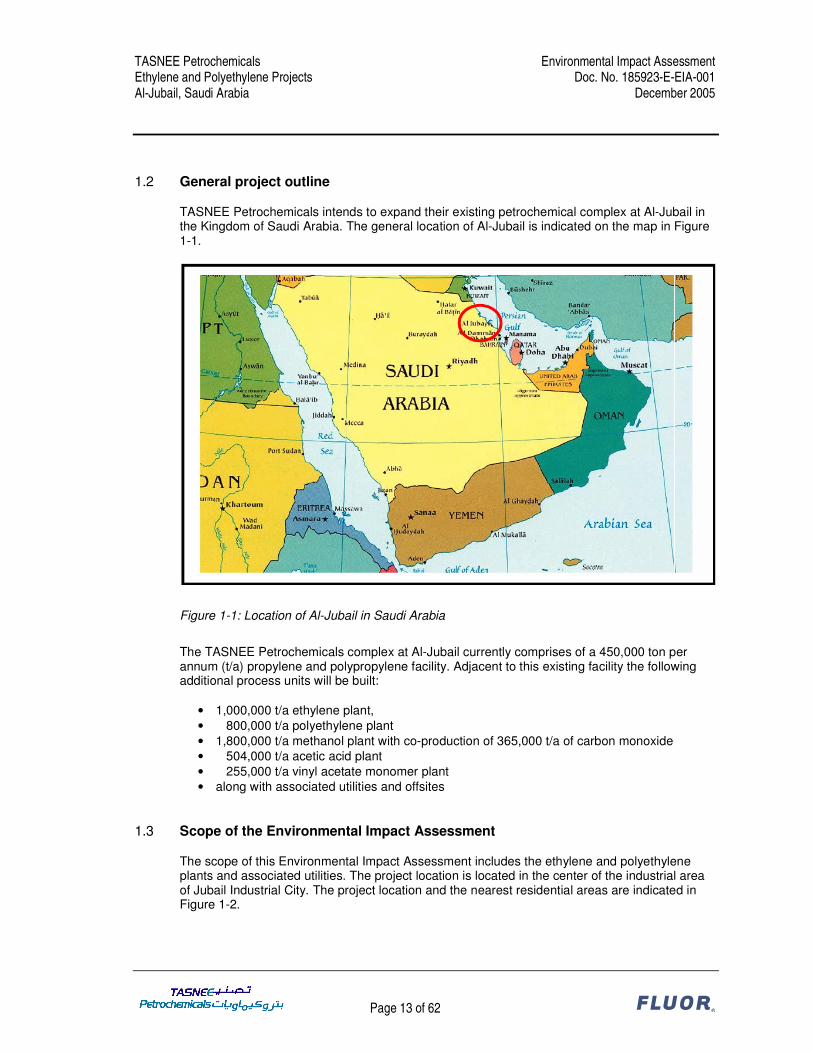
1.2 General project outline
TASNEE Petrochemicals intends to expand their existing petrochemical complex at Al-Jubail in the Kingdom of Saudi Arabia. The general location of Al-Jubail is indicated on the map in Figure 1-1.
Figure 1-1: Location of Al-Jubail in Saudi Arabia
The TASNEE Petrochemicals complex at Al-Jubail currently comprises of a 450,000 ton per annum (t/a) propylene and polypropylene facility. Adjacent to this existing facility the following additional process units will be built:
• 1,000,000 t/a ethylene plant, • 800,000 t/a polyethylene plant • 1,800,000 t/a methanol plant with co-production of 365,000 t/a of carbon monoxide • 504,000 t/a acetic acid plant • 255,000 t/a vinyl acetate monomer plant • along with associated utilities and offsites
1.3 Scope of the Environmental Impact Assessment
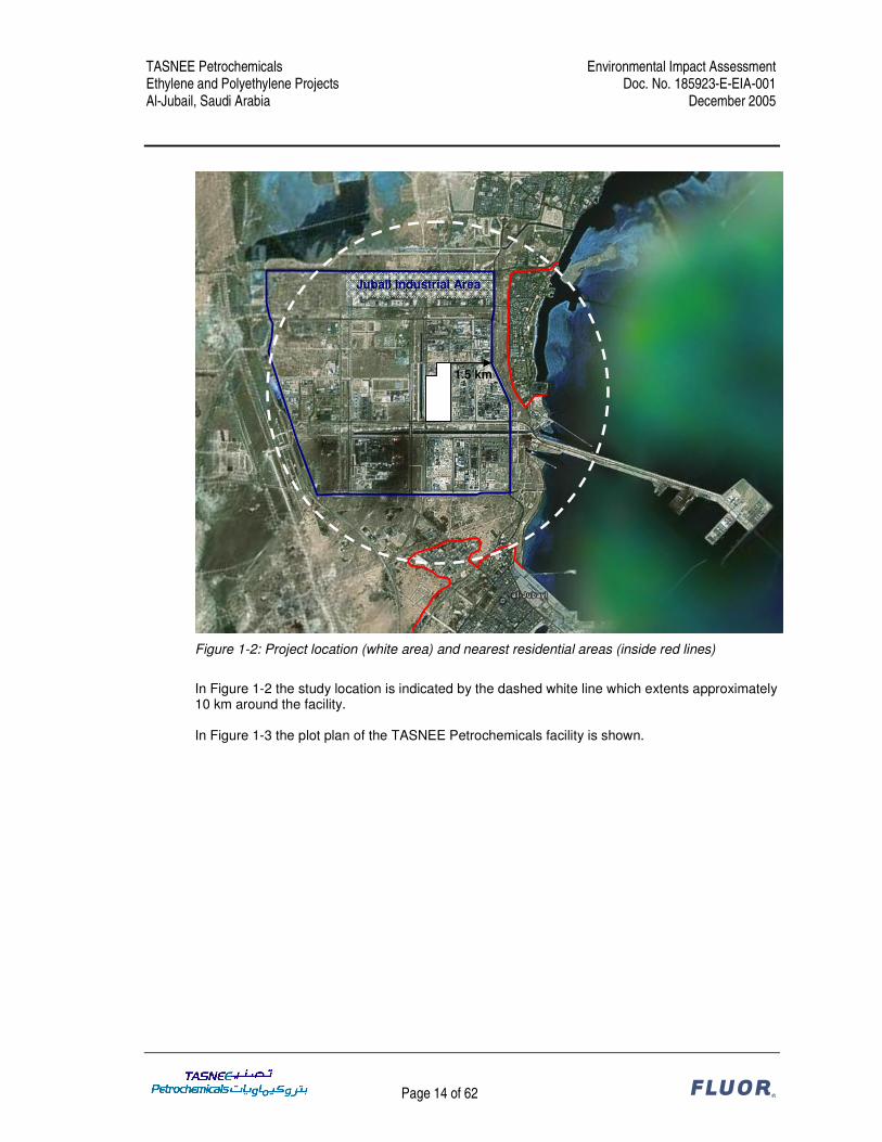
The scope of this Environmental Impact Assessment includes the ethylene and polyethylene plants and associated utilities. The project location is located in the center of the industrial area of Jubail Industrial City. The project location and the nearest residential areas are indicated in Figure 1-2.
TASNEE Petrochemicals Environmental Impact Assessment Ethylene and Polyethylene Projects Doc. No. 185923-E-EIA-001 Al-Jubail, Saudi Arabia December 2005
Page 14 of 62 ®
Figure 1-2: Project location (white area) and nearest residential areas (inside red lines)
In Figure 1-2 the study location is indicated by the dashed white line which extents approximately 10 km around the facility. In Figure 1-3 the plot plan of the TASNEE Petrochemicals facility is shown.
1.5 km
Jubail Industrial Area
TASNEE Petrochemicals Environmental Impact Assessment Ethylene and Polyethylene Projects Doc. No. 185923-E-EIA-001 Al-Jubail, Saudi Arabia December 2005
Page 15 of 62 ®
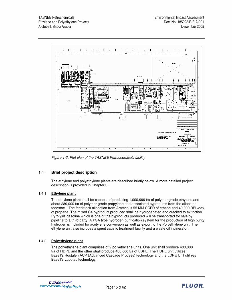
Figure 1-3: Plot plan of the TASNEE Petrochemicals facility
1.4 Brief project description
The ethylene and polyethylene plants are described briefly below. A more detailed project description is provided in Chapter 3.
1.4.1 Ethylene plant
The ethylene plant shall be capable of producing 1,000,000 t/a of polymer grade ethylene and about 280,000 t/a of polymer grade propylene and associated byproducts from the allocated feedstock. The feedstock allocation from Aramco is 55 MM SCFD of ethane and 40,000 BBL/day of propane. The mixed C4 byproduct produced shall be hydrogenated and cracked to extinction. Pyrolysis gasoline which is one of the byproducts produced will be transported for sale by pipeline to a third party. A PSA type hydrogen purification system for the production of high purity hydrogen is included for acetylene conversion as well as export to the Polyethylene unit. The ethylene unit also includes a spent caustic treatment facility and a waste oil incinerator.
1.4.2 Polyethylene plant
The polyethylene plant comprises of 2 polyethylene units. One unit shall produce 400,000 t/a of HDPE and the other shall produce 400,000 t/a of LDPE. The HDPE unit utilizes Basell’s Hostalen ACP (Advanced Cascade Process) technology and the LDPE Unit utilizes Basell’s Lupotec technology.
TASNEE Petrochemicals Environmental Impact Assessment Ethylene and Polyethylene Projects Doc. No. 185923-E-EIA-001 Al-Jubail, Saudi Arabia December 2005
Page 16 of 62 ®
1.4.2.1 HDPE unit For the ACP process catalyst is supplied by an external party and unloaded into catalyst storage vessels which feed the polymerization reactor through a catalyst dosing device after further dilution with hexane. Reactor feed comprising of ethylene, co-monomer & hydrogen is continuously fed to 3 reactors operated in series for multimodal production. Hexane solvent is pumped to the reactor. Hexane is recovered downstream from the powder product and recycled back to the reactors. Co-catalyst is added to the recycle hexane stream. Polymerization occurs at a pressure of 5 to 10 bar and at a temperature of 75 - 90°C. The heat of reaction is removed with cooling water. The polymer slurry flows out of the reactor and the powder and the mother liquor are separated initially in a centrifuge and later on by using fluidized bed dryers. The powder is then sent to the extruder for pelletizing. In order to manufacture colored grades a dedicated extruder sized for plant design capacity with necessary downstream equipment is also presently envisaged.
1.4.2.2 LDPE unit Basell’s Lupotec technology utilizes a tubular reactor for the production of LDPE. The process essentially involves pressurizing ethylene to 2600-3100 bar and feeding a tubular reactor which typically has an internal diameter of 1.2-3.2 inches and is 1500-2000 meters in length depending on the plant capacity. Peroxide as initiator is directly fed to the reactor. The feed temperature is raised to 130-180 °C to start the strongly exothermic reaction and cooling is used to prevent the reactants from exceeding 330 °C. Hot water is used in tube jackets generating medium pressure & low pressure steam. Per pass conversion of 25 to 35% is achieved based on grade. To improve heat transfer high gas velocities are used and depending upon the grade the reactor pressure control valve at the end of the reactor is operated in either “kicking” or “non-kicking” mode. The reactor pressure control valve discharges the LDPE/ethylene mixture into a high pressure separator. In the separator most of the ethylene is removed and recycled. The polymer melt is further depressurized to 1 bar in the low pressure product separator. The melt is then sent to the extruder for pelletizing and further degassing.
1.5 Abbreviations / Acronyms used
AA Acetic Acid ACP Advanced Cascade Process APC Air Pollution Control BAT Best Available Technology BBL Barrel BFW Boiler Feed Water BOD Biological Oxygen Demand CPI Corrugated Plate Interceptor COD Chemical Oxygen Demand EA / EIA Environmental (Impact) Assessment
TASNEE Petrochemicals Environmental Impact Assessment Ethylene and Polyethylene Projects Doc. No. 185923-E-EIA-001 Al-Jubail, Saudi Arabia December 2005
Page 17 of 62 ®
ECC Environmental Consent to Construct EIR Environmental Information Report EPC Engineering, Procurement and Construction EPO Environmental Permit to Operate ESD Emergency Shutdown and Depressurization HAP Hazardous Air Pollutant HDPE High Density PolyEthylene ISO International Organization for Standardization KSA Kingdom of Saudi Arabia LDAR Leak Detection And Repair LDPE Low Density PolyEthylene MP Medium Pressure PM10 Particulate Matter smaller than 10 micrometer PP PolyPropylene PSA Pressure Swing Adsorption RC Royal Commission for Al-Jubail and Yanbu RCER Royal Commission Environmental Regulations RP Receiver Point SCFD Standard Cubic Feet per Day TOC Total Organic Carbon VAM Vinyl Acetate Monomer VHP Very High Pressure VOC Volatile Organic Compound WB The World Bank Group WWTP Waste Water Treatment Plant
TASNEE Petrochemicals Environmental Impact Assessment Ethylene and Polyethylene Projects Doc. No. 185923-E-EIA-001 Al-Jubail, Saudi Arabia December 2005
Page 18 of 62 ®
2 REGULATORY FRAMEWORK
2.1 World Bank Standards
The World Bank Group’s “Pollution Prevention and Abatement Handbook” (Handbook, ref. 1) effective July 1998 contains the relevant WB standards. The Handbook consists of three major sections. The first deals with an overview of key policy lessons in pollution management. The second contains guidelines mainly meant for local government policy makers on establishing a sound environmental policy. The third part contains the Project Guidelines. Part II of the Handbook contains a section on The Environmental Assessment Process. The environmental assessment (EA) process is one of the tools of the World Bank to enhance projects by helping prevent, minimize, mitigate or compensate any adverse environmental or social impacts. Within the EA process the project’s potential environmental and social impacts are screened and the project is assigned to one of three categories: • Category A: full EIA is required • Category B: no full EIA is required, but some environmental analysis is necessary • Category C: no EIA or environmental analysis is required Since typical category B projects entail rehabilitation, maintenance or upgrading rather than new construction, it can be concluded that the TASNEE Petrochemicals Ethylene and Polyethylene Projects have to be classified as a category A project. When a project is classified as category A, an EIA report has to be prepared. In writing this report, the guidelines on report preparation as mentioned in the Handbook have been taken into account. In assessing the environmental impacts of the project, the environmental standards from the Project Guidelines on Petrochemical Manufacturing have been followed.
2.2 Kingdom of Saudi Arabia Standards
The relevant standards from the local authorities are contained in the “Royal Commission Environmental Regulations 2004” (RCER, ref. 2). The RCER have been compiled by the Environmental Control Department of the Royal Commission for Jubail and Yanbu Industrial Cities. The RCER consists of two volumes. Volume 1 provides an overview of the environmental regulatory system and lists the standards and regulations. Volume 2 outlines the requirements for the environmental permit package and contains the forms to be used for the permit application. All new industrial facilities are required to join the RC’s Consolidated Permit Program. This program governs all procedures associated with obtaining the necessary Environmental Consent to Construct (ECC) and Environmental Permit to Operate (EPO). The operator shall obtain an ECC from the RC before starting construction of a new facility. The operator of a new facility shall not operate it or carry out process commissioning without a valid EPO issued by the RC. The RCER contain environmental standards on emissions to air, emissions to water, hazardous materials management, waste management, dredging, noise, and reporting and record keeping.
TASNEE Petrochemicals Environmental Impact Assessment Ethylene and Polyethylene Projects Doc. No. 185923-E-EIA-001 Al-Jubail, Saudi Arabia December 2005
Page 19 of 62 ®
For the TASNEE Petrochemicals Ethylene and Polyethylene Projects an Environmental Information Report (ref. 3-5) has been prepared to demonstrate compliance of the design with the KSA standards and to apply for an Environmental Consent to Construct and an Environmental Permit to Operate.
2.3 Comparison of World Bank vs. KSA standards
The relevant standards of the WB and the KSA have been reviewed and these have been compared to the design of the TASNEE Petrochemicals Ethylene and Polyethylene projects. The results of the review of the environmental standards and how these standards are incorporated into the design of the project are documented in three Environmental Compliance Reports, which are included as Attachment 1, 2 and 3. In these reports, the applicable WB standards have been tabled together with the KSA standards. In those cases where WB standards have been defined and either less stringent or no KSA standards are defined, the design approach has been reported. The comparison between the relevant standards of the WB, KSA and the plant design approach shows that in general either the KSA standards meet the WB standards or that the design approach meets the WB standards. Regarding the emission of particulate matter, the waste oil incinerator and the spent caustic incinerator are compliant with the KSA standards but the WB standard is more stringent. For the waste oil incinerator the particulate matter emission will be further investigated during vendor selection. For the spent caustic incinerator a BAT analysis is included as an attachment to the Environmental Compliance Report for the Ethylene project showing an emission reduction efficiency of 99.6%.
TASNEE Petrochemicals Environmental Impact Assessment Ethylene and Polyethylene Projects Doc. No. 185923-E-EIA-001 Al-Jubail, Saudi Arabia December 2005
Page 20 of 62 ®
3 PROJECT DESCRIPTION
3.1 Ethylene plant
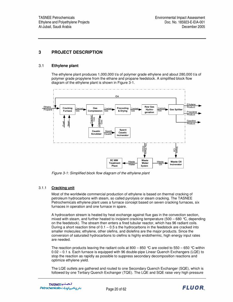
The ethylene plant produces 1,000,000 t/a of polymer grade ethylene and about 280,000 t/a of polymer grade propylene from the ethane and propane feedstock. A simplified block flow diagram of the ethylene plant is shown in Figure 3-1.
Figure 3-1: Simplified block flow diagram of the ethylene plant
3.1.1 Cracking unit
Most of the worldwide commercial production of ethylene is based on thermal cracking of petroleum hydrocarbons with steam, so called pyrolysis or steam cracking. The TASNEE Petrochemicals ethylene plant uses a furnace concept based on seven cracking furnaces, six furnaces in operation and one furnace in spare. A hydrocarbon stream is heated by heat exchange against flue gas in the convection section, mixed with steam, and further heated to incipient cracking temperature (500 – 680 °C, depending on the feedstock). The stream then enters a fired tubular reactor, which has 96 radiant coils. During a short reaction time of 0.1 – 0.5 s the hydrocarbons in the feedstock are cracked into smaller molecules; ethylene, other olefins, and diolefins are the major products. Since the conversion of saturated hydrocarbons to olefins is highly endothermic, high energy input rates are needed. The reaction products leaving the radiant coils at 800 – 850 °C are cooled to 550 – 650 °C within 0.02 – 0.1 s. Each furnace is equipped with 96 double-pipe Linear Quench Exchangers (LQE) to stop the reaction as rapidly as possible to suppress secondary decomposition reactions and optimize ethylene yield. The LQE outlets are gathered and routed to one Secondary Quench Exchanger (SQE), which is followed by one Tertiary Quench Exchanger (TQE). The LQE and SQE raise very high pressure
TASNEE Petrochemicals Environmental Impact Assessment Ethylene and Polyethylene Projects Doc. No. 185923-E-EIA-001 Al-Jubail, Saudi Arabia December 2005
Page 21 of 62 ®
(VHP) steam which is supplied to a steam drum. The TQE preheats boiler feed water (BFW) which is routed to an economizer coil system in the convection section of the furnace. Optimum waste heat recovery is achieved by routing the hot flue gases leaving the radiant section to the convection section where the heat contained in the flue gas is transferred to the feed/steam streams as well as to VHP steam and BFW. The radiant boxes of the furnaces are equipped with low-NOx floor and side wall burners. The burners are normally fired with H2 rich fuel gas from the ethylene unit and, if required, mixed with import fuel gas (C1 – C3) to achieve the necessary fuel quantities. Decoking of the furnace is required periodically to remove carbonaceous deposits from the cracking coils and quench exchangers. The decoking is carried out by using an air/steam mixture to completely burn off the coke. The decoke operation will typically require 36 hours and eliminates the need for mechanical cleaning. Decoke gases containing particulate coke are routed to a cyclone to separate the coke from the effluent gases.
3.1.2 Product separation
The cracked gas from the furnace is compressed from a pressure of 1.25 bara to 36 bara in five stages with intercooling. The discharge temperatures of the compressor stages are kept below 90 °C to prevent polymerization reactions. Between the 4th and the 5th stage sour gases are removed in the caustic scrubber. The cracked gas is cooled and dried before it is routed to the raw gas hydrogenation section, where all acetylene contained in the cracked gas is converted to ethylene and ethane and most of the heavier acetylenes and dienes are converted to the corresponding monoolefins or paraffins. In subsequent separation steps, first the C2
- fraction is separated from the C3+ fraction. The C2
- fraction is cooled down until most of the C2 components can be separated from hydrogen and methane in the demethanizer. The bottom product of the demethanizer is fed to the C2 Splitter from where ethane is recovered and recycled to the cracking furnaces and ethylene is sent to the ethylene refrigeration system. Here the ethylene product is compressed to the required battery limit pressure or alternatively liquefied for storage (30,000 ton cryogenic low-pressure tank). The C3
+ fraction is sent to the depropanizer. The overhead product from the depropanizer is fed to the C3 Splitter from where propane is recovered and recycled to the cracking furnaces and the propylene product is normally pumped directly to battery limit or alternatively is sent to the propylene storage tank (20,000 ton cryogenic low-pressure tank). The bottom of the depropanizer is fed to the debutanizer. It is separated into a C4 fraction and a gasoline fraction. The C4 fraction is hydrogenated and subsequently recycled to the cracking furnaces. The gasoline is cooled and routed to gasoline product storage.
3.1.3 PSA unit
The hydrogen purification unit or pressure swing adsorber (PSA) provides the hydrogen required for the C4 hydrogenation. The PSA unit purifies the hydrogen from the demethanizer to produce high purity hydrogen. The purification is performed by adsorption of accompanying components such as methane, CO and N2. The process is based on the physical adsorption phenomena, whereby highly volatile compounds with low polarity as hydrogen are practically non-adsorbable compared to molecules CO, CO2, N2 and hydrocarbons. Hence, most impurities in a hydrogen-
TASNEE Petrochemicals Environmental Impact Assessment Ethylene and Polyethylene Projects Doc. No. 185923-E-EIA-001 Al-Jubail, Saudi Arabia December 2005
Page 22 of 62 ®
containing stream can be selectively adsorbed and high-purity hydrogen product is obtainable. The off-gas from the PSA unit is returned to the cracked gas compression.
3.1.4 Cooling tower
The cooling water system is a closed loop cooling water system exchanged against seawater. The cooling water system is one common system to supply cooling water to the Ethylene and PE plants and also to other plants (Methanol, VAM, AA and existing PP). The seawater cooling tower is used to cool the closed loop cooling water. Seawater is supplied to the cooling tower from the existing seawater pump basin. The seawater blow down from the cooling tower is routed to the seawater return basin through the existing seawater return header. Chlorination of the seawater is provided by the hypochlorite generator package. Corrosion inhibitor, scale inhibitor and biocide are fed into the system intermittently to ensure the quality of the cooling water.
3.1.5 Waste water system
Waste water from the ethylene plant is sent to the oily waste water basin. The collected waste water is sent to the benzene stripper where dissolved benzene is removed by steam stripping and sent to the flare stack. Treated waste water from the benzene stripper is sent to a CPI separator to separate oil and water. The skimmed oil of the CPI separator is pumped to the waste oil tank and incinerated in the waste oil incinerator together with other waste oils. The separated water from the CPI separator is sent to the waste water holding basin and pumped to the Royal Commission Waste Water Treatment Plant. Caustic wastewater drains are collected in the waste caustic surge basin and pumped to the spent caustic tank. The spent caustic is incinerated by the spent caustic incinerator.
3.1.6 Slop system
The slop system is designed to empty the plant of all liquid hydrocarbons. It consists of two underground collection drums and a pump for each drum. Inventories will be discharged by the pumps to the waste oil incinerator storage.
3.1.7 Flare stack
The flare system is designed to collect all combustible gases and liquids which are discharged in case of emergencies, equipment malfunctions, start-up and shut-down, to feed them to a controlled safe combustion point. The flare system applies the elevated flare concept. The sour gas flare was not considered because the spent caustic is sent to the spent caustic incinerator. MP steam is used as a smokeless medium for proper combustion of main flare and to reduce the formation of soot.
3.1.8 Waste oil incinerator
The waste oil incinerator comprises of a vertically aligned thermal oxidizer chamber and an exhaust stack on top of it. The waste oils of the ethylene plant and the polyethylene plant are collected in a common storage tank and sent to the incinerator via a pump as one combined stream.
TASNEE Petrochemicals Environmental Impact Assessment Ethylene and Polyethylene Projects Doc. No. 185923-E-EIA-001 Al-Jubail, Saudi Arabia December 2005
Page 23 of 62 ®
The thermal oxidizer employs a single stage combustion process for the conversion of the waste oil stream to gaseous products of combustion, e.g. CO2, SO2 and water vapor. It ensures almost complete destruction of the waste streams by high temperature and high intensity combustion. The burner is highly versatile and capable of burning a wide range of liquid wastes with a corresponding large variation of excess air. The hot combustion products from the thermal oxidizer are discharged directly into the exhaust stack located on top of the combustion chamber. The flue gas is analyzed for oxygen content to ensure correct excess oxygen levels in the thermal oxidizer. A temperature sensor controls the excess air to prevent excessive thermal NOx generation. The destruction removal efficiency for organic compounds is more than 99.99%.
3.1.9 Spent caustic incinerator
The spent caustic incinerator comprises of a thermal oxidizer, quench unit, air pollution control (APC) system, plume suppression unit and exhaust stack. The thermal oxidizer employs a single stage combustion process and ensures a high destruction efficiency of the waste components. The combustion gases are rapidly cooled using an indirect quench recycle cooler. The rapid cooling freezes the chemical reactions taking place in the combustion process and, as a result, eliminates the conditions that would otherwise be favorable for the formation of dioxins and furans. The quenched and water-saturated flue gas stream is discharged into a separation vessel for water droplet disengagement. Subsequently, the gases enter the APC system to remove sub-micron salt particles and SO2 from the flue gas. The plume suppression unit, a direct gas fired air heater, is designed to comply with the RCER that no visible plume may exist at the stack exit. The scrubbed and treated flue gas from the APC system is mixed with the flue gas from the plume suppression unit within the exhaust stack and discharged to atmosphere. The destruction removal efficiency for organic compounds is more than 99.99%. The removal efficiency for particulate matter is 99.6% and for SO2 is 97%.
TASNEE Petrochemicals Environmental Impact Assessment Ethylene and Polyethylene Projects Doc. No. 185923-E-EIA-001 Al-Jubail, Saudi Arabia December 2005
Page 24 of 62 ®
3.2 HDPE plant
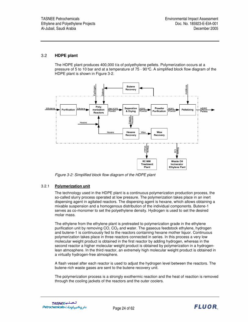
The HDPE plant produces 400,000 t/a of polyethylene pellets. Polymerization occurs at a pressure of 5 to 10 bar and at a temperature of 75 - 90°C. A simplified block flow diagram of the HDPE plant is shown in Figure 3-2.
Figure 3-2: Simplified block flow diagram of the HDPE plant
3.2.1 Polymerization unit
The technology used in the HDPE plant is a continuous polymerization production process, the so-called slurry process operated at low pressure. The polymerization takes place in an inert dispersing agent in agitated reactors. The dispersing agent is hexane, which allows obtaining a mixable suspension and a homogenous distribution of the individual components. Butene-1 serves as co-monomer to set the polyethylene density. Hydrogen is used to set the desired molar mass. The ethylene from the ethylene plant is pretreated to polymerization grade in the ethylene purification unit by removing CO, CO2 and water. The gaseous feedstock ethylene, hydrogen and butene-1 is continuously fed to the reactors containing hexane mother liquor. Continuous polymerization takes place in three reactors connected in series. In this process a very low molecular weight product is obtained in the first reactor by adding hydrogen, whereas in the second reactor a higher molecular weight product is obtained by polymerization in a hydrogen-lean atmosphere. In the third reactor, an extremely high molecular weight product is obtained in a virtually hydrogen-free atmosphere. A flash vessel after each reactor is used to adjust the hydrogen level between the reactors. The butene-rich waste gases are sent to the butene recovery unit. The polymerization process is a strongly exothermic reaction and the heat of reaction is removed through the cooling jackets of the reactors and the outer coolers.
TASNEE Petrochemicals Environmental Impact Assessment Ethylene and Polyethylene Projects Doc. No. 185923-E-EIA-001 Al-Jubail, Saudi Arabia December 2005
Page 25 of 62 ®
At certain intervals, the reactors and the outer coolers have to be cleaned from polyethylene film layers. Polyethylene adhering to the inner walls is dissolved in hexane. The hexane is recovered in the waste water distillation vessel.
3.2.2 Powder separation and drying
After mechanical separation of the hexane and HDPE powder in decanter centrifuges, screw conveyors supply the hexane-moist HDPE powder to the two-stage fluid bed dryer. In the dryer the residual hexane contained in the HDPE powder is evaporated by means of hot nitrogen to a residual content < 1wt%. The nitrogen used for powder drying is in a closed circuit. The nitrogen leaving the dryer and containing hexane is passed through the nitrogen scrubbing tower to remove the hexane before being used again in the dryer. The dried HDPE powder is passed through a vibrating screen to separate oversized particles. Through a rotary feeder the HDPE powder is pneumatically conveyed to the powder purification unit. Nitrogen circulated in a closed circuit is used as carrier gas. In the purification unit the powder flows through a silo in plug flow with a counter-current flow of nitrogen and steam to reduce the hexane level below 100 ppm-wt and to destroy catalyst residues. The purified HDPE powder is discharged to the pelletizing powder bin.
3.2.3 Pelletizing and pellet conveying
In the pelletizing unit the essential quality characteristics and properties of the HDPE are set by homogenization and by mixing with additives. All additives are added to the HDPE powder and are thoroughly mixed. The powder mixture is melted, thoroughly kneaded and homogenized. In the pelletizer the polymer melt is pressed through a die plate, cut off by a rotating blade and then cooled in a water bath. The pellets are separated from the water, dried, cooled, transferred to homogenizers and mixed. The on-spec products are pneumatically conveyed to the pellet silos of the logistic centre.
3.2.4 Hexane recovery
The hexane recovery unit comprises of evaporation, distillation, adsorptive and absorptive purification of the hexane mother liquor used as dispersing agent. In the evaporation stage, wax and other impurities are removed from the hexane mother liquor and sent to the wax recovery unit. The hexane vapors are condensed and the components that can not be condensed are supplied to the butene recovery unit for further treatment. The mother liquor stream is fed to the hexane distillation column and the purified hexane is pumped to the adsorption towers. Adsorptive purification of hexane is achieved by means of a specific silica gel, which removes dissolved impurities formed during polymerization as well as water and oxygen. The purified hexane leaving the adsorption column overhead is transferred to the distilled hexane tank.
TASNEE Petrochemicals Environmental Impact Assessment Ethylene and Polyethylene Projects Doc. No. 185923-E-EIA-001 Al-Jubail, Saudi Arabia December 2005
Page 26 of 62 ®
3.2.5 Wax recovery
One of the by-products obtained during polymerization is an amorphous polyethylene wax, which is dissolved in the dispersing agent hexane. Hexane-containing wax solution is obtained from the hexane separator/evaporator. In a jacketed pipe hexane is evaporated and subsequently separated in a flash vessel. Steam is injected at the bottom of the flash vessel to improve the hexane removal from the wax. The wax is discharged from the flash vessel to movable bin or can be solidified on a cooled belt conveyor and broken in pieces and filled into big bags in the wax flaked production unit. To ensure undisturbed operation, all discharge lines, the wax storage vessel and the pumps are heated with low-pressure steam to prevent clogging of equipment in this part of the plant.
3.2.6 Butene recovery
In a scrubbing tower butene-rich waste gases from different sources as well as very pure hexane vapors are treated to recover butene/hexane and feed it back to the process. Feed gas is treated in counter-current flow with hexane fed from the top of the scrubbing tower. The butene-enriched hexane is collected in the column bottom. The off-gas leaving the scrubber on top is nearly free of butene and contains mainly hydrogen and only little quantity of hexane. This gas stream is normally recycled back to the first reactor.
3.2.7 Catalyst handling
The catalyst used in the polymerization is the so-called THS-G catalyst, which is prepared by Basell and furnished as a powder delivered in drums. The catalyst powder drums are emptied into nitrogen-blanketed filling devices. After emptying several drums into the filling vessel, the vessel is isolated and discharged into the catalyst suspension vessel. Normally no hexane is used, only in the case the catalyst is not flowing freely the content is flushed out with hexane. By adding hexane to the catalyst suspension vessel, the catalyst is diluted according to recipe. To destroy catalyst poisons a certain amount of triethylaluminium is added. From the catalyst suspension vessel the catalyst is discharged to the catalyst intermediate vessel. From this vessel the catalyst is continuously supplied to the reactors via dosing pumps.
3.2.8 Waste water system
The waste water obtained in the process units of the HDPE plant is subjected to pre-treatment before being transferred to the Royal Commission Waste Water Treatment Plant. Surface water and drainage water from the paved areas is collected in the wastewater pit. This pit is emptied into the waste water tank, which also collects the waste water from various operational units. The waste water tank is blanketed with nitrogen. In the waste water tank hexane and HDPE powder float on top of the water phase and are separated by a skimmer. The waste water is pumped to the Royal Commission Waste Water Treatment Plant.
TASNEE Petrochemicals Environmental Impact Assessment Ethylene and Polyethylene Projects Doc. No. 185923-E-EIA-001 Al-Jubail, Saudi Arabia December 2005
Page 27 of 62 ®
3.3 LDPE plant
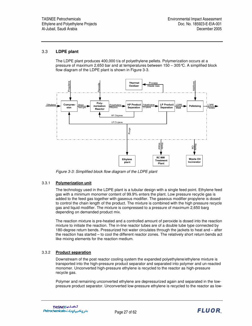
The LDPE plant produces 400,000 t/a of polyethylene pellets. Polymerization occurs at a pressure of maximum 2,650 bar and at temperatures between 150 – 305°C. A simplified block flow diagram of the LDPE plant is shown in Figure 3-3.
Figure 3-3: Simplified block flow diagram of the LDPE plant
3.3.1 Polymerization unit
The technology used in the LDPE plant is a tubular design with a single feed point. Ethylene feed gas with a minimum monomer content of 99.9% enters the plant. Low pressure recycle gas is added to the feed gas together with gaseous modifier. The gaseous modifier propylene is dosed to control the chain length of the product. The mixture is combined with the high pressure recycle gas and liquid modifier. The mixture is compressed to a pressure of maximum 2,650 barg depending on demanded product mix. The reaction mixture is pre-heated and a controlled amount of peroxide is dosed into the reaction mixture to initiate the reaction. The in-line reactor tubes are of a double tube type connected by 180-degree return bends. Pressurized hot water circulates through the jackets to heat and – after the reaction has started – to cool the different reactor zones. The relatively short return bends act like mixing elements for the reaction medium.
3.3.2 Product separation
Downstream of the post reactor cooling system the expanded polyethylene/ethylene mixture is transported into the high-pressure product separator and separated into polymer and un-reacted monomer. Unconverted high-pressure ethylene is recycled to the reactor as high-pressure recycle gas. Polymer and remaining unconverted ethylene are depressurized again and separated in the low-pressure product separator. Unconverted low-pressure ethylene is recycled to the reactor as low-
TASNEE Petrochemicals Environmental Impact Assessment Ethylene and Polyethylene Projects Doc. No. 185923-E-EIA-001 Al-Jubail, Saudi Arabia December 2005
Page 28 of 62 ®
pressure recycle gas and a small part of the recycle gas is purged from the system to remove inerts and secondary modifiers. The purge gas is sent to the ethylene plant for processing.
3.3.3 Pelletizing and pellet conveying
The polyethylene melt is sent from the low-pressure product separator via the extruder to the underwater face cutter system. The pellets are cooled and transported with water to the pellet spin dryer. Additives like anti-block and slip agent can be fed to the main extruder. After drying the pellets are pneumatically conveyed to the pellet silos.
3.3.4 Hot water system
One of the special features of the Basell Lupotech TS ® process is the design of the hot water system which optimally reduces the consumption of cooling water and maximizes the possible recovery of the exothermic reaction heat of polymerization. The LP and MP hot water are used to feed the water circuits for the reactor cooling jackets, pre-heater and for the first stage cooling of the high pressure recycle. The heat gained by the water is converted to steam by adiabatic flashing. The steam generated is used in steam condensers.
3.3.5 Regenerative thermal oxidizer
The process waste gas is fed to a self cleaning dust filter and subsequently sent to the regenerative thermal oxidizer. The emission control efficiency is 99%. The off-gases of the regenerative thermal oxidizer are discharged to atmosphere by a stack.
3.4 Feedstock and product profile
The TASNEE Petrochemicals expansion is an integrated ethylene and polyethylene project. The ethylene that is produced in the cracker will be used in the HDPE and LDPE plants. The feedstock and product profile is summarized in Table 3-1.
TASNEE Petrochemicals Environmental Impact Assessment Ethylene and Polyethylene Projects Doc. No. 185923-E-EIA-001 Al-Jubail, Saudi Arabia December 2005
Page 29 of 62 ®
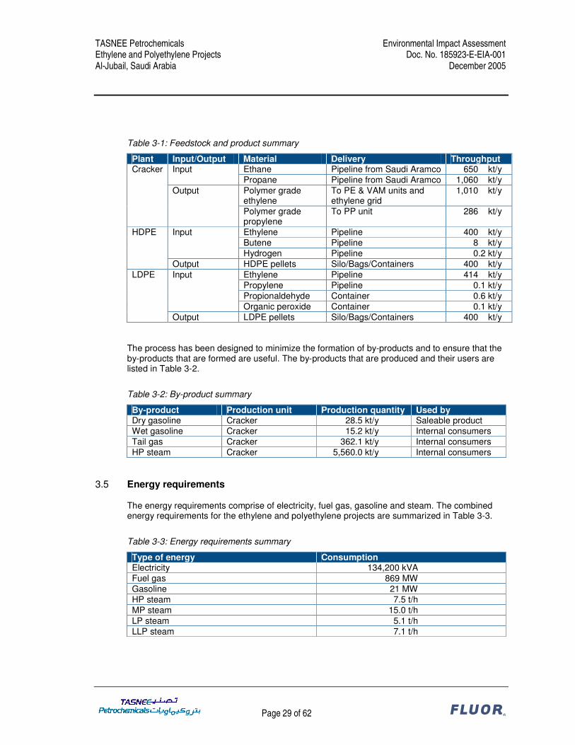
Table 3-1: Feedstock and product summary
Plant Input/Output Material Delivery Throughput Ethane Pipeline from Saudi Aramco 650.0 kt/y Input Propane Pipeline from Saudi Aramco 1,060.0 kt/y Polymer grade ethylene
Output LDPE pellets Silo/Bags/Containers 400.0 kt/y The process has been designed to minimize the formation of by-products and to ensure that the by-products that are formed are useful. The by-products that are produced and their users are listed in Table 3-2.
Table 3-2: By-product summary
By-product Production unit Production quantity Used by Dry gasoline Cracker 28.5 kt/y Saleable product Wet gasoline Cracker 15.2 kt/y Internal consumers Tail gas Cracker 362.1 kt/y Internal consumers HP steam Cracker 5,560.0 kt/y Internal consumers
3.5 Energy requirements
The energy requirements comprise of electricity, fuel gas, gasoline and steam. The combined energy requirements for the ethylene and polyethylene projects are summarized in Table 3-3.
Table 3-3: Energy requirements summary
Type of energy Consumption Electricity 134,200 kVA Fuel gas 869 MW Gasoline 21 MW HP steam 7.5 t/h MP steam 15.0 t/h LP steam 5.1 t/h LLP steam 7.1 t/h
TASNEE Petrochemicals Environmental Impact Assessment Ethylene and Polyethylene Projects Doc. No. 185923-E-EIA-001 Al-Jubail, Saudi Arabia December 2005
Page 30 of 62 ®
4 BASELINE ENVIRONMENTAL AND SOCIAL CONDITIONS
4.1 Environmental Baseline Study
An extensive desktop review exercise has been undertaken to establish the current environmental quality of the proposed site. There is not much specific data available for the Al-Jubail area. In Attachment 4 an overview of the desktop research results is presented on the environmental and social conditions for Saudi Arabia as a whole with some specific issues for the Al-Jubail area. This chapter elaborates on the limited knowledge that is available specific for the Al-Jubail area.
4.2 Socio-economic environment
4.2.1 Demography
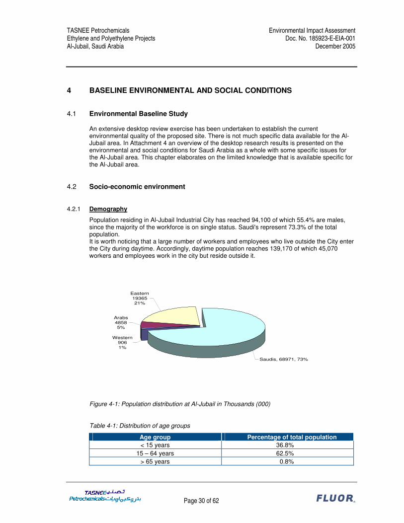
Population residing in Al-Jubail Industrial City has reached 94,100 of which 55.4% are males, since the majority of the workforce is on single status. Saudi's represent 73.3% of the total population. It is worth noticing that a large number of workers and employees who live outside the City enter the City during daytime. Accordingly, daytime population reaches 139,170 of which 45,070 workers and employees work in the city but reside outside it.
Eastern1936521%
Arabs48585%
Western9061%
Saudis, 68971, 73%
Figure 4-1: Population distribution at Al-Jubail in Thousands (000)
Table 4-1: Distribution of age groups
Age group Percentage of total population < 15 years 36.8%
15 – 64 years 62.5% > 65 years 0.8%
TASNEE Petrochemicals Environmental Impact Assessment Ethylene and Polyethylene Projects Doc. No. 185923-E-EIA-001 Al-Jubail, Saudi Arabia December 2005
Page 31 of 62 ®
4.2.2 Economic activity
The share of the two major industrial cities Al-Jubail and Yanbu of the GDP is 8% and by excluding the Oil Industry the share is 12%. The share of the Kingdom’s Industrial output is 60% and by excluding the Oil Industry is 80%. The percentage of Al-Jubail and Yanbu Industrial workforce is 19% of the total Industrial workforce of the Kingdom.
4.2.3 Employment characteristics
The Labor Law is protective of employees in general and overrides conflicting contractual provisions agreed under another jurisdiction, unless they are beneficial to the employee. The Ministry of Labor issues a model form of labor contract in Arabic which is widely used, but other forms of contract are enforceable, provided they comply with the Labor Law. End-of-contract gratuities are equivalent to 15 Days the salary for every year of the first five years of service and 30 days for every year thereafter.
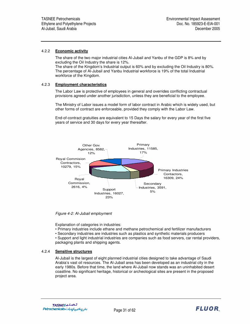
Primary Industries Contactors, 16309, 24%
Secondary Industries, 3591,
5%
Royal Commision Contractors, 10279, 15%
Other Gov. Agencies, 8582,
12%
Primary Industries, 11585,
17%
Royal Commission,
2616, 4%Support
Industries, 16027, 23%
Figure 4-2: Al-Jubail employment
Explanation of categories in industries: • Primary industries include ethane and methane petrochemical and fertilizer manufacturers • Secondary industries are industries such as plastics and synthetic materials producers • Support and light industrial industries are companies such as food servers, car rental providers, packaging plants and shipping agents.
4.2.4 Sensitive structures
Al-Jubail is the largest of eight planned industrial cities designed to take advantage of Saudi Arabia’s vast oil resources. The Al-Jubail area has been developed as an industrial city in the early 1980s. Before that time, the land where Al-Jubail now stands was an uninhabited desert coastline. No significant heritage, historical or archeological sites are present in the proposed project area.
TASNEE Petrochemicals Environmental Impact Assessment Ethylene and Polyethylene Projects Doc. No. 185923-E-EIA-001 Al-Jubail, Saudi Arabia December 2005
Page 32 of 62 ®
4.2.5 Infrastructure
4.2.5.1 General The Royal Commission for Al-Jubail and Yanbu (RCJY) is responsible for providing, or helping to provide, the necessary infrastructure for Al-Jubail and Yanbu Industrial Cities, on a highly reliable standard. Basically, utilities such as Electric Power, Potable Water, Seawater for Cooling, Sanitary and Industrial Wastes in the two industrial cities fall under the responsibility of Marafiq Co. Some of the infrastructures are provided by other entities. For example; Electricity at Al-Jubail is provided by the Saudi Electric Company (SEC), Desalinated Water is partially provided by the Sea Water Conversion Corporation (SWCC), Natural Gas is provided by Saudi Aramco while Telecommunication services are provided by the Saudi Telecommunications Co. (STC)��The Royal Commission has a long term investment strategy in infra-structural projects to be able to support new activities in the city of Al-Jubail 2.
4.2.5.2 Transportation and roads Al-Jubail has a very modern road network built on international standards and integrates with national road Networks.
4.2.5.3 Potable water Saline Water Conversion Corporation pumps 136,000 cubic meters of desalinated water per day to cover most of the City's consumption. The RC desalination plants provide supplementary quantities to meet the daily requirement levels. The actual consumption level at the time of writing this report was 899,161 cubic meters per day pumped through a 782-km network feeding both the residential and the industrial areas.
4.2.5.4 Sewers / Waste water treatment Domestic and industrial wastes are collected and treated at RC owned and operated centralized facilities. The total capacity of the wastewater treatment facilities is 72,000 cubic meters per day. 44,896 cubic meters of wastewater is processed daily; 44,432 cubic meters of treated water is reclaimed daily. Treated water is used for irrigation; excess treated water being stored for future needs. Sewage treatment plants contribute greatly to reservation of potable water, ecological programs, improvement of public health and the widespread of greenery.
4.2.5.5 Electricity Saudi Electric Company (SEC) supplies the Al-Jubail Industrial City with electricity for all its needs through a 1716-km network. The consumption is in the range of 831 and 1613 megawatts supplied to 16,500 consumers representing industries, households, commercial installations and public facilities. Capacity has been contracted for the project.
4.2.5.6 Waste disposal sites The Royal Commission has implemented strict policies for the management of industrial waste (hazardous or non-hazardous wastes) generated by industrial facilities, plants and companies in Al-Jubail Industrial City. These policies aim at minimizing impacts on the environment and provide safe and permanent disposal solution. Waste is being observed carefully from generation to safe disposal. Regular inspection by Royal Commission on industrial facilities and monitoring of waste storage handling, transportation and disposal methods is carried out to ensure that generators are following proper management policies. A private specialized company operates a waste treatment and disposal facility with operations comprising of incineration, pretreatment, stabilization, evaporation and land filling.
TASNEE Petrochemicals Environmental Impact Assessment Ethylene and Polyethylene Projects Doc. No. 185923-E-EIA-001 Al-Jubail, Saudi Arabia December 2005
Page 33 of 62 ®
4.3 Physical environment
4.3.1 Terrain and topography
Saudi Arabia is approximately 1,969,000 square kilometers occupying 2/3 of the Arabian Peninsula and is bounded by the Red Sea in the west and the Arabian Gulf in the east. Al-Jubail is situated at the east coast of Saudi Arabia. It is located on the So-called Arabian platform. The terrain is flat with no natural water ways. It is a barren area with a harsh climate.
4.3.2 Land use and land cover
4.3.2.1 Industrial land use The Royal Commission has successfully developed Al-Jubail into a world class industrial city with an area of 1,016 sq km, of which 5,500 Hectares is in industrial use. The success of Al-Jubail 1 has led to the need for expansion in Al-Jubail in order to satisfy the future investment demand. This new development is called Al-Jubail 2 and will double the industrial area of Al-Jubail Industrial City. The Royal Commission has implemented this development to support the Kingdoms national development strategy. This will be accomplished through a phased development which will add an additional site area of 5,508 Hectares.
4.3.2.2 Commercial, institutional and residential land uses The residential community is located in the north of the industrial zone. It is comprised of 8 districts of which Al-Fanateer and Al-Deffi have been developed primarily by the Royal Commission and partly by the private developers. The primary (retail / commercial) center is located in Al-Fanateer with expansion work under progress to suit the growing Al-Jubail community.
4.3.2.3 Military land use The city of Al-Jubail played a crucial role during Operations Desert Shield and Desert Storm. Almost all Marine Corps personnel and many Army units deployed through this port city. The Navy positioned several fleet hospitals in the area, and the Air Force had units on the ground to support airlift missions and medical evacuation missions. In general it can be stated that there are various American and British army bases in use in Saudi Arabia and more specific in the Al-Jubail area.
4.3.2.4 Nature reserves and aesthetic environments The city of Al-Jubail is not located in the vicinity of reserves or aesthetic environments.
TASNEE Petrochemicals Environmental Impact Assessment Ethylene and Polyethylene Projects Doc. No. 185923-E-EIA-001 Al-Jubail, Saudi Arabia December 2005
Page 34 of 62 ®
4.3.3 Climate and meteorology
Average temperatures and precipitation for the study area are indicated in Table 4-2.
4.3.4.1 General Discharge of cooling seawater, ballast water and certain types of industrial waste water are regulated to preserve the marine environment. Presently, the Royal Commission routinely monitors water quality in the Gulf adjacent to the city, seawater cooling system, groundwater and wastewater from industrial facilities.
4.3.4.2 Gulf water Thirteen water quality monitoring stations have been established by the Royal Commission to give comprehensive picture of water quality. These stations allow the measurement of water quality changes near the coast and offshore. Routine monitoring gives an early indication of long-term trends, allowing action to be taken to prevent damages if there is a need. At each of the water quality monitoring stations, an electronic probe is used to determine several water quality parameters, including temperature, salinity, dissolved oxygen, and pH. Samples from several depths are also collected for more comprehensive analysis. At the Royal Commission Environmental Laboratory, samples are analyzed for physical and chemical parameters including heavy metals and organic compounds. Results are then entered into a computerized database and periodic reports are generated.
4.3.4.3 Seawater Cooling System The Royal Commission performs routine monitoring of the once-through, non-contact seawater cooling system to enable continued compilation of baseline data for possible future determination of short term impacts on water quality.
4.3.4.4 Groundwater The Royal Commission conducts a comprehensive groundwater monitoring program to prevent degradation of natural groundwater quality, as the city grows.
TASNEE Petrochemicals Environmental Impact Assessment Ethylene and Polyethylene Projects Doc. No. 185923-E-EIA-001 Al-Jubail, Saudi Arabia December 2005
Page 35 of 62 ®
Groundwater in the vicinity of industrial processes, waste management facilities, and storage tanks is closely monitored for early detection of contaminants.
4.3.4.5 Industrial Wastewater Industrial wastewater is discharged to the central wastewater treatment facilities where is treated using the latest technology and used for irrigation. Wastewater quality is monitored for compliance with discharge standards. The influent and effluent of the central wastewater treatment facilities are also monitored to ensure that only waste which can effectively be treated are received and treated. In addition, the treated wastewater used for irrigation is monitored to ensure it complies with the irrigation water quality standards.
4.3.4.6 Oil Spill Protection In order to facilitate early detection of oil and chemical spills, and to protect recreational beaches and vital operations such as the cooling water canal and the intake to the desalination plant, the Royal Commission has established an oil spill monitoring program. The Royal Commission has also developed an emergency response plan for oil and chemical spills.
4.3.5 Geology
4.3.5.1 Overview of geology
The area around Al-Jubail has been developed during the Paleozoic (540-250 Ma), Mesozoic (250-65 Ma), and Cenozoic (65 Ma to Recent) (collectively referred to as Phanerozoic cover), and crop out as relatively flat lying beds of sedimentary rocks such as sandstone, siltstone, limestone, and evaporites (salt deposits), and volcanic rocks.
4.3.5.2 Geohazards � Saudi Arabia is known to be in a seismic active area. As figure below indicates this is not a
threat for the study area. It is located far away from both the Eurasian plate as well as the African plate.
TASNEE Petrochemicals Environmental Impact Assessment Ethylene and Polyethylene Projects Doc. No. 185923-E-EIA-001 Al-Jubail, Saudi Arabia December 2005
Page 36 of 62 ®
� The study area is not considered to be endangered by volcanic eruptions. � Flooding in the study area is limited due to the generally low relief, gentle gradient and high
infiltration rates in the east coastal area.
4.3.6 Hydrology and drainage pattern
There are no fresh water bodies in the study area present. Rainfall is known to be easily absorbed in the soil. No flooding during heavy rainfall periods is observed. Information on ground water levels in not available. It is assumed not to be critical since this is under the responsibility of the Royal Commission. The RC has an extensive project investment plan on all infrastructural issues in the Al-Jubail area.
TASNEE Petrochemicals Environmental Impact Assessment Ethylene and Polyethylene Projects Doc. No. 185923-E-EIA-001 Al-Jubail, Saudi Arabia December 2005
Page 37 of 62 ®
4.3.7 Air Quality
Background data of the ambient air quality was obtained from sampling stations located in the Al-Jubail industrial area. Sampling station 1 (27.01.21 N, 49.32.44E) and sampling station 9 (27.02.05N, 49.37.30E) provide the background data for SO2, NOx and PM10. For statistics of background data see Attachment 5.
Table-4-3: Background ground level pollutant data (per year), station 1
Figure 4-3: Location of site and sampling stations
Meteorological data for 2002, 2003 and 2004, was obtained from a meteorological station based in Dhahran. The distance between Dhahran and the site in Al-Jubail is approximately 85 km. The
TASNEE Petrochemicals Environmental Impact Assessment Ethylene and Polyethylene Projects Doc. No. 185923-E-EIA-001 Al-Jubail, Saudi Arabia December 2005
Page 38 of 62 ®
use of meteorological data from stations located this far is not uncommon. However, to verify local data for wind speed and direction were compared. The prevailing wind direction for both the Al-Jubail and the Dhahran site are north and northwest. Wind speeds between 2 and 8 m/s are dominant for both sites.
Figure 4-4: Wind rose (meteorological data 2001-2004)
4.3.8 Ambient noise
There are no noise monitoring data available for the area. However, it is obvious that noise is a significant environmental issue as the Al-Jubail Industrial City includes many industrial activities, which all have their noise sources. Therefore, KSA regulations require that the noise level at the property line of each individual company is allowed to be maximum 75 dB(A). The TASNEE facility is designed to comply with this requirement. Noise levels for the TASNEE facility are modeled and evaluated in Chapter 5.
4.4 Biological environment
4.4.1 Environmental protection areas
Saudi Arabia has a well developed system to identify, develop and maintain environmental protection areas. At present the National Commission for Wildlife Conservation and Development manages 17 protected areas. A short description of 14 of these protected areas is provided in Attachment 4. Al-Jubail is located approximately 300 kilometer from the nearest reserve which is the Ibex reserve at Hawtah bini Tamin in the middle of Saudi Arabia.
4.4.2 Terrestrial Flora and Fauna
The study area is a relative barren area with not much flora and fauna present. It is part of an industrial area and is not considered an ecological corridor. The whole east coast is of the same geographical origin with not much specific habitat for wildlife.
TASNEE Petrochemicals Environmental Impact Assessment Ethylene and Polyethylene Projects Doc. No. 185923-E-EIA-001 Al-Jubail, Saudi Arabia December 2005
Page 39 of 62 ®
4.4.3 Marine ecosystems
The study area is located next to the Gulf Sea which is a source of abundant wildlife. This ecosystem is carefully protected by monitoring of the waste water streams to the Gulf. All waste water is treated by the Royal Commission in a dedicated waste water treatment plant.
4.4.4 Endangered and threatened species
Saudi Arabia has several endangered species in their Kingdom. According the 2004 IUCN red list of threatened species 4 species are recorded as critically endangered, 10 species are considered endangered and 30 species are classified as vulnerable. Details of the species can be found in Attachment 4. The habitat of these species is not in the vicinity of the industrial zone of Al-Jubail.
4.5 Overall environmental and social baseline assessment
The study area is part of an industrial zone which has been developed in the eighties. It is developed under strict governmental supervision by the Royal Commission. World standards have been adopted to develop Al-Jubail. The city already has a well developed workforce that works in the industrial facilities. The project baseline is that of a modern industrial zone. No major impact is envisaged for the social and environmental issues. However special attention has to be given to air quality and noise since these are project specific issues which can have an impact even in a developed industrial area. These issues are addressed in detail in Chapter 5.
TASNEE Petrochemicals Environmental Impact Assessment Ethylene and Polyethylene Projects Doc. No. 185923-E-EIA-001 Al-Jubail, Saudi Arabia December 2005
Page 40 of 62 ®
5 ENVIRONMENTAL AND SOCIAL IMPACTS
5.1 Emissions to air
The facility includes boilers, incinerators, flares and stacks as part of the process design, and the main process materials are volatile hydrocarbons, so there will be gaseous emissions from the facility. The impact of continuous emission sources on ambient air quality has been studied by air quality modeling. The results of the air modeling study are described in Chapter 5.1.1. As the project will process light hydrocarbons in a country which has high ambient temperatures, unless prevented there is a potential for volatile organic compounds to evaporate and escape into the atmosphere. This is addressed in Chapter 5.1.2.
5.1.1 Air quality
Gaseous emissions normally are of concern for large combustion processes in relation to local ambient air quality. Pollutants are sulfur dioxide, nitrogen oxides and particulate matter. These combustion products have been shown to have an impact on health if ambient levels are allowed to rise too high. The proposed TASNEE site is located in an industrial area, already having a significant number of continuous emission sources venting to atmosphere. This air quality study aims to demonstrate the impact of the emissions from the TASNEE site on the overall background concentration and aims to predict the future overall concentration. As a basis for this study the World Banks’ Pollution Prevention and Abatement Handbook 1998 is used as a basis for air quality conditions since the Royal Commission does not specify pollutant concentrations at ground level, see Table 5-1.
Table 5-1: World Bank ambient air quality requirements
Pollutant Concentration (µµµµg/m3)
Particulate matter Annual arithmetic mean Maximum 24-hour average
50 70
Nitrogen Oxides Maximum 24-hour average
150
Sulfur Dioxide Annual arithmetic mean Maximum 24-hour average
50
125
5.1.1.1 Dispersion calculation For normal operation the software model used was the AERMOD Version 3.3.15 using the Breeze Graphical User Interface as supplied by Trinity Consultants. This model is used as a standard for regulatory air modeling in the USA and is generally accepted internationally. AERMOD is a multi source Gaussian model which is suitable for predicting long (annual) to short term (1 hour) average atmospheric concentrations of pollutants arising from various types of sources. The model uses Pasquill-Gifford dispersion parameters to characterize atmospheric turbulence and the Briggs relationship to determine plume rise.
TASNEE Petrochemicals Environmental Impact Assessment Ethylene and Polyethylene Projects Doc. No. 185923-E-EIA-001 Al-Jubail, Saudi Arabia December 2005
Page 41 of 62 ®
For the ethylene facility the following units are considered as continuous emission sources: • Vent stacks of furnaces (3H-0101, 0201, 0301, 0401, 0501, 0601) • Boilers (3PK-8001 A/B) • Waste Oil Incinerator • Spent Caustic Incinerator For the Low Density Poly Ethylene (LDPE) facility the vent stack (6ST4201) of the regenerative thermal oxidizer is considered as a continuous emission source. AERMOD requires four types of information in order to calculate the ground level concentration, e.g. meteorological data, terrain data, source data, receiver data. The source data identified for the TASNEE facility are in listed in Table 5-2.
Table 5-2: Continuous emission source model input data
6ST4201 25 0.5 5.0 50 13 0 - Meteorological data is made fit for use with a meteorological preprocessor. This processor calculates the boundary layer parameters for the representative site of the modeling domain. Latitude and longitude parameters of the site and a set of three parameters which characterize the site are the basic input. These three land-use parameters are the surface roughness length, the Bowen ratio (a measure of the moisture available for evaporation) and the Albedo (a measure of how much of the solar radiation is reflected). The site is divided in sections and the parameters are allocated for each section. The output file contains information about the entire planetary boundary layer consisting of single level data as well as data for various elevations. For this simulation however a ‘ready-for-modeling’ data set was used (provided by Trinity Consultants) which already addresses the land-use surrounding the TASNEE site. The terrain preprocessor is used by AERMOD to account for changes in elevations. Given the generally level and low lying topography of the TASNEE coastal plane, assuming the area is level for modeling purposes will not significantly affect model results. The model was set up to calculate the highest ground level concentration estimated at 350 m intervals over a 12 km x 11.5 km grid for both the 24-hour average and the annual average. Building downwash has not been taken into account since structures to be placed on the site will be largely skeletal (steel frameworks supporting process units), thereby reducing their potential effect in causing plume downwash. Stacks will be at a height sufficient to clear these structures. Therefore, by not considering buildings within the modeling process there is some potential for modeled levels near to the facility being lower than otherwise, and for modeled levels remote from the facility being slightly higher. As the most sensitive populations will be remote from the
TASNEE Petrochemicals Environmental Impact Assessment Ethylene and Polyethylene Projects Doc. No. 185923-E-EIA-001 Al-Jubail, Saudi Arabia December 2005
Page 42 of 62 ®
site, and reasonable factors of safety must be applied near to the site, this is considered acceptable.
5.1.1.2 Results SO2 Sulfur Dioxide is released from combustion processes due to sulfur in the fuel being oxidized. Making use of low sulfur content fuels ensures a low emission rate to the environment. Figure 5-1 to Figure 5-4 shows the modeled ambient sulfur dioxide levels resulting from modeling the facility over two averaging periods, respectively the 24 hrs and the annual average.
TASNEE Petrochemicals Environmental Impact Assessment Ethylene and Polyethylene Projects Doc. No. 185923-E-EIA-001 Al-Jubail, Saudi Arabia December 2005
TASNEE Petrochemicals Environmental Impact Assessment Ethylene and Polyethylene Projects Doc. No. 185923-E-EIA-001 Al-Jubail, Saudi Arabia December 2005
Page 44 of 62 ®
Figure 5-3: SO2 levels (Annual average, 3-years)
Figure 5-4: SO2 levels (Annual average, 3-years)
TASNEE Petrochemicals Environmental Impact Assessment Ethylene and Polyethylene Projects Doc. No. 185923-E-EIA-001 Al-Jubail, Saudi Arabia December 2005
Page 45 of 62 ®
The maximum concentrations (µg/m3) calculated over a 3 year period are listed below: 1. 1.51274 (04-12-16) 2. 1.49420 (03-12-07) 3. 1.47740 (04-12-18) 4. 1.44805 (04-11-28) 5. 1.30722 (02-12-10) 6. 1.30085 (03-10-29) 7. 1.27761 (04-11-24) 8. 1.25342 (03-12-08) 9. 1.24756 (02-02-12) 10 1.23121 (03-01-24) Discrete receptors (sampling station 1 and 9) are located outside the contours. Sampling station 1 is located at the bottom right of the figure (354614E; 2989772N) and is exposed to a maximum 24-hour concentration of 0.1 µg/m3. Sampling station 9 at the left (363613E; 2991025N) is exposed to a maximum 24-hour concentration of 0.09 µg/m3.
5.1.1.3 Conclusion SO2 When comparing the contribution of the TASNEE facility for the discrete receptor maximum concentration levels (0.1 and 0.09µg/m3) to the existing concentration levels (max. 90.5 µg/m3 and averaged 3.7 µg/m3) it can be seen that the contribution of SO2 emissions from the TASNEE facility will be limited. Compared with the World Bank standard of 125 µg/m3 it can be concluded that the additional SO2 emission from this project combined with the existing background level will remain within acceptable levels. Therefore, the contribution of sulfur dioxide emissions from the TASNEE project to local ambient levels is considered to have a marginal environmental impact.
5.1.1.4 Results NOx In most ambient situations, nitric oxide is emitted from combustion sources and rapidly oxidised into nitrogen dioxide (the most significant form in relation to human health). It is assumed that all oxides of nitrogen are therefore present as nitrogen dioxide. This gives a conservative result. On the TASNEE site low NOx burners are being used to ensure a low emission rate of NOx to the environment. Figure 5-5 to Figure 5-8 show the modeled ambient nitrogen dioxide levels resulting from modeling the facility over two averaging periods, respectively the 24 hrs and the annual average.
TASNEE Petrochemicals Environmental Impact Assessment Ethylene and Polyethylene Projects Doc. No. 185923-E-EIA-001 Al-Jubail, Saudi Arabia December 2005
TASNEE Petrochemicals Environmental Impact Assessment Ethylene and Polyethylene Projects Doc. No. 185923-E-EIA-001 Al-Jubail, Saudi Arabia December 2005
Page 47 of 62 ®
Figure 5-7: NO2 levels (Annual average, 3-years)
Figure 5-8: NO2 levels (Annual average, 3-years)
TASNEE Petrochemicals Environmental Impact Assessment Ethylene and Polyethylene Projects Doc. No. 185923-E-EIA-001 Al-Jubail, Saudi Arabia December 2005
Page 48 of 62 ®
The maximum concentrations (µg/m3) calculated over a 3 year period are listed below: 1. 46.41880 (04122824) 2. 44.89687 (03102924) 3. 41.88943 (02021224) 4. 41.61853 (03050124) 5. 41.57676 (04052024) 6. 39.72370 (02011224) 7. 39.17365 (03121324) 8. 38.85189 (02110724) 9. 38.72104 (02021324) 10. 38.71534 (04120224) Discrete receptors (sampling station 1 and 9) are located outside the contours. Sampling station 1 is located at the bottom right of the figure (354614E; 2989772N) and is exposed to a maximum 24-hour concentration of 2.9 µg/m3. Sampling station 9 at the left (363613E; 2991025N) is exposed to a maximum 24-hour concentration of 3.0 µg/m3.
5.1.1.5 Conclusion NOx When comparing the contribution of the TASNEE facility for the discrete receptor maximum concentration levels (2.9 and 3.0µg/m3) to the existing concentration levels (max. 307 µg/m3 and averaged 28.2 µg/m3) it can be seen that the contribution of NOx emissions from the TASNEE facility will be limited. Compared with the World Bank standard of 150 µg/m3 it can be concluded that the additional NOx emission from this project combined with the existing background level will remain within acceptable levels. Therefore, the contribution of nitrogen dioxide emissions from the TASNEE project to local ambient levels is considered to have a marginal environmental impact.
5.1.1.6 Results and conclusion PM10 The maximum 24-hour concentration levels of the TASNEE facility for PM10 are calculated to be 1 µg/m3 within the fence line and 0.1 µg/m3 at the nearest receptor location within the residential areas. The available background concentration data is very limited and only includes the year 2002 for one meteo station, see Table-4-3. Therefore, no comparison is made to the background levels. Compared with the World Bank standard of 70 µg/m3 it can be concluded that the impact of the additional PM10 emission from this project will be limited. Therefore, the contribution of the emission of particulate matter from the TASNEE project to local ambient levels is considered to have a marginal environmental impact. In Chapter 2.3 it was stated that the emissions of particulate matter from the waste oil incinerator and the spent caustic incinerator are designed to comply with the RC environmental standards. However, the WB emission limit for incinerator stacks is more stringent than the RCER. Based on the ambient air quality it can be concluded that both incinerators have an acceptable emission level and a marginal environmental impact.
TASNEE Petrochemicals Environmental Impact Assessment Ethylene and Polyethylene Projects Doc. No. 185923-E-EIA-001 Al-Jubail, Saudi Arabia December 2005
Page 49 of 62 ®
5.1.2 Volatile organic compounds
Within the Ethylene and Polyethylene projects continuous emissions of volatile organic compounds (VOCs) do not occur. The only emissions of VOCs are fugitive emissions arising from leakage of valves, flanges or other equipment. In the design fugitive emissions are prevented, e.g. by using double mechanical seals for pumps in VOC and HAP service. All equipment in VOC or organic HAP service shall be monitored on a minimum of semi-annual basis conform Royal Commission requirements. According the RCER, the operator may revert to annual leak detection monitoring only after two consecutive semi-annual leak detection periods during which the number of leaking components is found to be less than 2% of the total. If the number of leaking components ever exceeds 2%, the operator shall revert to semi-annual monitoring. All equipment in VOC or organic HAP service that register more than 10,000 ppm VOC and valves, flanges or connectors in organic HAP service that register more than 500 ppm VOC are defined by the RCER as leaking components. All leaks from pressure relief valves shall be stopped within 24 hours of detection. All other leaking components shall be tagged immediately and replaced or repaired within 15 calendar days or, if unit or plant shutdown is required, at the next scheduled shutdown.
5.2 Emissions to water
Direct discharges to surface water do not occur for this facility. Wastewater is either sent to the Royal Commission Industrial Wastewater Treatment Plant or to the Royal Commission Sanitary Wastewater Treatment Plant. Storm water will be sent to the Royal Commission storm water drainage system. The facility has the capacity to retain 3 days of industrial wastewater production. Independent of the industrial wastewater system, the facility has the system to collect the first flush of storm water, considered to be the first 30 mm of rainfall from any storm event, from industrial process areas and hazardous material storage and handling areas. The wastewater effluent of the facility will be pre-treated to ensure compliance to the Royal Commission criteria for discharge to their water treatment facilities.
5.3 Solid and hazardous wastes
Solid wastes produced in the facility are mainly spent catalyst and waste from packaging materials or maintenance activities. The spent catalyst will be returned to the vendor for recycling when practicable or will be sent to a licensed disposal facility otherwise. A waste oil incinerator is part of this project to combust hazardous organic wastes. This is considered an effective treatment technology for petrochemical organic wastes.
TASNEE Petrochemicals Environmental Impact Assessment Ethylene and Polyethylene Projects Doc. No. 185923-E-EIA-001 Al-Jubail, Saudi Arabia December 2005
Page 50 of 62 ®
5.4 Ambient noise
5.4.1 Introduction
The objective of this assessment is to demonstrate that the noise impact of the Project is in compliance with the “Pollution prevention and abatement handbook 1998” of the World Bank. The Handbook states the following:
The Royal Committee environmental regulations, which serve as the legal reference, define the following noise limits: 75 dB(A) measured at the property line and 50 dB(A) for Residential Areas.
5.4.2 Technical Evaluation
The overall technical evaluation has been performed with the IMMI program of Wölfel. The ISO 9613 calculation model has been used. Noise sources used in the calculations are described in the Attachment 6. Main noise sources identified are the Sea Water Cooling Tower, some large Air cooled Heat Exchangers and the large Compressors inside the Ethylene Plant. Because these noise sources are large compared to the other main sources, these sources have been modeled separately. Other identified noise sources have been joined together in groups of noise sources. The sound power of each group of noise sources is in the same order of magnitude as the sources modeled. The project is located inside a large industrial area has been taken into account by setting a damping factor according to ISO 9613 for industrial sites. Most calculation models (also ISO 9613) calculate the downwind noise propagation. The wind rose together with the orientation of the plant, see Figure 5-9 shows that the nearest residential area is not located downwind of the plant.
TASNEE Petrochemicals Environmental Impact Assessment Ethylene and Polyethylene Projects Doc. No. 185923-E-EIA-001 Al-Jubail, Saudi Arabia December 2005
Page 51 of 62 ®
Figure 5-9: Situation map of the project (blue grid), residential areas (red grid), receiver points (black and white circles) and wind rose
Two Receiver Points were defined; RP1: that is the closest to the plant, located upwind of the Project. RP2: the nearest residential area that can be, in some conditions slightly downwind of the plant. For the calculation and model definition, the north angle has been turned 43°.
TASNEE Petrochemicals Environmental Impact Assessment Ethylene and Polyethylene Projects Doc. No. 185923-E-EIA-001 Al-Jubail, Saudi Arabia December 2005
Page 52 of 62 ®
Figure 5-10: Receiver points
The calculation has been performed with the noise sources as described in Attachment 6.
5.4.3 Results
Figure 5-11 shows the mapping of the noise caused by the project for the nearby area (without the satellite photo background)
Figure 5-11: Noise map near the plant (impact of the project only)
TASNEE Petrochemicals Environmental Impact Assessment Ethylene and Polyethylene Projects Doc. No. 185923-E-EIA-001 Al-Jubail, Saudi Arabia December 2005
Page 53 of 62 ®
Figure 5-12 shows the noise map in a wider area where also the residential areas are present.
Figure 5-12: Noise map showing impact caused by the project near residential areas
RP1 is exposed to 37.3 dB(A). This is the result of the straight calculation; because the plant is located upwind of this receiver point, the actual noise level will be minimal 3 dB less, thus 34.3 dB(A). RP2 is being exposed to 26.3 dB(A). The contribution of the various sound sources to these figures can be found in Attachment 7.
5.4.4 Conclusions
5.4.4.1 Residential areas The noise limit as set by the World Bank Standards for a noise receptor inside a residential area is 45 dB(A). The noise portion added by the project is maximum 34.3 dB(A) for RP1. Impact on the noise limit can be neglected, as it will be less than 0.35 dB on 45 dB(A). This is very well within the limit of 3dB(A) increase as per World Bank Guidelines.
5.4.4.2 Industrial area The noise limit as set by the World Bank Pollution Prevention and Abatement Handbook for a noise receptor inside an industrial area is 70 dB(A). Figure 5-11 shows maximum noise levels of 75 dB(A) at the project property line facing the sea water cooling tower. This complies with the Royal Commission guidelines; for the rest the noise levels are generally less than 70 dB(A). The noise caused by the project at the boundary of the industrial area will be max. 50 dB(A) which is well below the 70 dB(A) as per World Bank Pollution Prevention and Abatement Handbook 1998.
TASNEE Petrochemicals Environmental Impact Assessment Ethylene and Polyethylene Projects Doc. No. 185923-E-EIA-001 Al-Jubail, Saudi Arabia December 2005
Page 54 of 62 ®
5.5 External safety
The risk due to loss of containment in the Ethylene and Polyethylene plants will generally be contained within the fence. Only in case of large leaks of ethane/propane or ethylene, mainly in the ethylene plant, jet fires or explosions could cause damage to neighboring facilities. In view of the fact that the nearest residential area is located more than 2 kilometer away, hazardous effects for residential areas will be negligible. Within the design phase of this project various safety studies have been conducted to identify potential hazards and implement effective preventive and mitigation measures, such as Emergency Shutdown and Depressurization (ESD) systems, fire fighting systems and fire & gas detection systems.
5.6 Visual impact
The project is developed within an industrial zone. Within the project a flare stack of 150 meters height is foreseen. This will be visible in the skyline of the industrial zone. The nearest residential areas are more than 2 kilometer away from the proposed flare stack. Its impact is assessed to be of minor importance.
5.7 Social impacts
There are a number of residential communities and their associated facilities within the study area. Key impacts are associated with the construction phase of the project. Potential impact during the construction phase include a temporary increase in the use of institutional facilities in the local communities, a temporary increase in employment opportunities for the local workforce and a temporary increase in demand for local commercial facilities and local trades. Since Al-Jubail already has a well developed workforce and the construction phase will be temporary, the impact will be limited. Once the facility has been built it will create an opportunity for extra employment. This will have a minor positive impact on the local economy.
TASNEE Petrochemicals Environmental Impact Assessment Ethylene and Polyethylene Projects Doc. No. 185923-E-EIA-001 Al-Jubail, Saudi Arabia December 2005
Page 55 of 62 ®
6 ANALYSIS OF ALTERNATIVES
There are a number of different technologies available for all three types of plants i.e. Ethylene plant, LDPE plant and HDPE plant. Although there are differences in each technology, e.g. type of reactor or number of reactors, they all employ the same type of operations within enclosed systems. From an environmental perspective all available technologies have similar environmental issues. For Steam Crackers for ethylene production the main environmental issues are: � Flue gases from furnaces and boilers � Spent Caustic For LDPE and HDPE plants the main environmental issues are: � Degassing of polyethylene pellets � Decomposition reactions in LDPE tubular reactor For these environmental aspects the following measures are implemented in the design: Flue gases from furnaces and boilers Furnaces and boilers will be provided with low NOx burners, which ensure that the NOx emissions from the furnaces and boilers are state of the art and well below both Royal Commission requirements and Worldbank standards. Further, low sulfur fuels will be used for the furnaces and boilers, which results in very low SO2 emissions. Spent Caustic When hydrogen sulfide (H2S) is scrubbed from hydrocarbon streams, the resulting sulfidic caustic, so-called spent caustic, has high biological and chemical demands (BOD and COD) and a strong objectionable odor, making it environmentally unacceptable. For this stream an incinerator with Air Pollution Control (APC) System will be implemented. The incinerator will effectively oxidize both sulfur and organic substances. Acid gases; i.e. SO2 and inorganic salts from the incineration of the spent caustic are removed from the flue gas by an Air Pollution Control (APC) System. Quench water from the incinerator will be free of sulfides and organics and can be sent to the WWTP or the sea. Degassing of polyethylene pellets The polyethylene pellets are the final product after extrusion and are generally stored in product silos. The product silos are purged with air to evacuate any ethylene contained inside the pellets. The purge air from LDPE pellet silos contain appreciable amounts of ethylene, which cannot be vented to air directly. Therefore, a regenerative thermal oxidizer will be provided, which will destruct any hydrocarbons in the purge air. The purge air from HDPE pellet silos contains hardly any amounts of ethylene as the HDPE is degassed much more rigorously prior to extrusion to recover hexane. Therefore, purge air from HDPE silos is directly vented to atmosphere.
TASNEE Petrochemicals Environmental Impact Assessment Ethylene and Polyethylene Projects Doc. No. 185923-E-EIA-001 Al-Jubail, Saudi Arabia December 2005
Page 56 of 62 ®
Decomposition reactions in LDPE tubular reactor For LDPE there is one specific issue with potential environmental impact. This concerns the occurrence of a decomposition reaction in the reactor. In such an event the content of the entire (tubular) reactor needs to be discharged in order to avoid major reactor damage. Improved temperature control in the reactor is applied in Basell’s Lupotec technology to prevent decomposition reactions. Should a decomposition reaction occur the reactor will be depressurized through a quench which separates polyethylene powder from the ethylene gas. The ethylene gas will be discharged to atmosphere through a vent stack. From the above it can be concluded that potential environmental impact has been addressed in the design and that adequate measures have been taken to minimize the environmental impact.
TASNEE Petrochemicals Environmental Impact Assessment Ethylene and Polyethylene Projects Doc. No. 185923-E-EIA-001 Al-Jubail, Saudi Arabia December 2005
Page 57 of 62 ®
7 ENVIRONMENTAL MANAGEMENT PLAN
The Environmental Management Plan will include the policies, plans, procedures, required resources and monitoring to ascertain the quantity and quality of the principal emissions from the TASNEE project. Based on the Environmental Impact Assessment the following monitoring is envisaged to be executed to demonstrate that the TASNEE project is operated in compliance with KSA regulations and World Bank standards.
7.1 Construction & Commissioning
The following monitoring will be carried out during the construction and commissioning phase: • Air quality monitoring; • Noise Monitoring; • Monitoring of waste water that will be discharged to the Royal Commission WWTP; • Wastes leaving the site.
7.1.1 Air quality monitoring
The EPC Contractors will carry out qualitative inspections of dust throughout the construction and commissioning phases.
7.1.2 Noise Monitoring
Noise monitoring will be carried out at the construction work sites at the outset of construction activities to ensure that KSA Community Noise Limits are met and to identify any hearing protection requirements for the construction workforce.
7.1.3 Monitoring of Water discharged to Royal Commission waste water treatment facilities
Water from the packaged sewage treatment plants used in the accommodation camps will be monitored to ensure compliance with KSA regulations. Sampling as per KSA regulations (e.g. BOD, COD, Total Suspended Solids, oil and grease, total and faecal coliforms and discharge flow rate) will be performed.
7.1.4 Waste
Waste management during construction activities will be carried out according to a Waste Management Plan. Quantities of waste generated during construction as well as its disposal destination will be monitored leaving the site.
TASNEE Petrochemicals Environmental Impact Assessment Ethylene and Polyethylene Projects Doc. No. 185923-E-EIA-001 Al-Jubail, Saudi Arabia December 2005
Page 58 of 62 ®
7.2 Operational Phase
Monitoring during the operational phase will be in accordance with KSA regulations.
7.2.1 Air and Emissions Monitoring
Emissions from continuous sources such as the stacks of the furnaces, boilers and incinerators will be measured as per KSA regulations. As air quality monitoring is already performed by the Royal Commission in the Jubail Industrial City, it is envisaged that TASNEE will not establish an air quality measurement program.
7.2.2 VOCs
An ongoing fugitive leak detection and repair programme (LDAR) will be employed to minimise the atmospheric release of VOCs into the atmosphere as part of TASNEE’s ongoing commitment to environmental protection.
7.2.3 Noise Monitoring
Periodic boundary monitoring should be carried out to ascertain generated noise by the complex to demonstrate compliance to KSA regulations.
7.2.4 Land Quality Monitoring
It is not expected that a monitoring schedule is required to assess land quality impacts as the development provides mitigations for reducing this impact. The response to spills on the site is dealt with in the waste treatment strategy. If erosion of concrete pads that support structures of the complex is observed, this should be investigated. Infilling the eroded area with gravel may be sufficient to rectify the problem. If a structural assessment of the support is required this is expected to include assessment of the surrounding land quality.
7.2.5 Water and Wastewater Monitoring
All waste waters will be sampled prior to discharge to the Royal Commission waste water facilities for final treatment.
TASNEE Petrochemicals Environmental Impact Assessment Ethylene and Polyethylene Projects Doc. No. 185923-E-EIA-001 Al-Jubail, Saudi Arabia December 2005
Page 59 of 62 ®
8 GENERAL ASSESSMENT OF THE PROJECT
TASNEE Petrochemicals intends to expand their existing propylene and polypropylene petrochemical complex with an ethylene and polyethylene plant. The production of ethylene and polyethylene from finite, non-renewable resources implies that this expansion project will never be sustainable in absolute terms. However, numerous actions have been taken during project development to prevent negative impacts on the environment or the local community and any remaining negative impacts are minimized wherever practicable. This Environmental Impact Assessment has addressed the significant issues relating to the potential environmental and social impacts of the TASNEE project. The main findings on the potential project impacts are: • The project is located in the center of the industrial area of Jubail Industrial City. The area
has been developed as an industrial city in the 1980s and before that time the land was an uninhabited desert coastline. Significant cultural heritage or biological ecosystems are therefore not present at the project location nor can they be impacted by the TASNEE project;
• The main environmental issues relate to the impact of gaseous emissions from the TASNEE facilities on ambient air quality and to the impact of the noise levels generated by the process equipment;
• Gaseous emissions from large combustion processes contain the pollutants SOx, NOx and PM10. The impact of these emissions on the ambient air quality at the nearest residential areas has been studied and evaluated based on air quality modeling;
• For SOx the maximum 24-hour averaged contribution of the TASNEE facility at the receptor location amounts to 0.1 µg/m3. Compared to the average existing background concentration level of 3.7 µg/m3 and the World Bank standard of 125 µg/m3 it is concluded that the TASNEE facility has a marginal impact on the ambient SOx levels and that the total level will remain within acceptable levels;
• For NOx the maximum 24-hour averaged contribution of the TASNEE facility at the receptor location amounts to 3.0 µg/m3. Compared to the average existing background concentration level of 28.2 µg/m3 and the World Bank standard of 150 µg/m3 it is concluded that the TASNEE facility has a marginal impact on the ambient NOx levels and that the total level will remain within acceptable levels;
• For PM10 the maximum 24-hour averaged contribution of the TASNEE facility at the receptor location amounts to 0.1 µg/m3. Insufficient background data is available to evaluate the impact on the total ambient concentration level. Compared to the World Bank standard of 70 µg/m3 the impact of the additional PM10 emission from this project will be limited;
• The PM10 emissions of the waste oil incinerator and the spent caustic incinerator are designed to comply with the Royal Commission environmental standards. However, the World Bank emission limit for incinerator stacks is more stringent than the RCER. Since it was concluded that the impact of the additional PM10 emission from this project will be limited, it follows that both incinerators have an acceptable emission level and a marginal environmental impact;
• The noise level of the TASNEE project at the nearest residential receptor is calculated to be 34.3 dB(A). Compared to the World Bank standard for residential areas of 45 dB(A) during the nighttime the impact of the noise level of the TASNEE facility is not significant as it will be 0.35 dB(A) on 45 dB(A). Compared to the World Bank limit of maximum 3 dB(A) increase for
TASNEE Petrochemicals Environmental Impact Assessment Ethylene and Polyethylene Projects Doc. No. 185923-E-EIA-001 Al-Jubail, Saudi Arabia December 2005
Page 60 of 62 ®
any project, it can be concluded that the noise level of the TASNEE facility has a marginal impact;
• The noise level of the TASNEE project at the boundary of the industrial area is calculated to be 50 dB(A). This is well below the World Bank guideline of 70 dB(A) for industrial areas which confirms the conclusion that the noise level of the TASNEE facility has a marginal impact;
• The social impact of the TASNEE project during construction of the facility is related to a temporary demand for housing facilities, local trades and local workforce and will create additional utilization of local infrastructure. As the city was developed as a center for industrial activity it has a well developed infrastructure and well developed local workforce. Therefore, the impact of the construction of the facility will be limited;
• Once the facility has been built it will create an opportunity for extra employment. This will have a minor positive impact on the local economy.
This Environmental Impact Assessment shows that the potential environmental and social impacts of the TASNEE project have been taken into consideration during the development of this project. The project has been designed to prevent or reduce potential impacts and is subsequently designed to maximize the overall project sustainability.
TASNEE Petrochemicals Environmental Impact Assessment Ethylene and Polyethylene Projects Doc. No. 185923-E-EIA-001 Al-Jubail, Saudi Arabia December 2005
Page 61 of 62 ®
9 REFERENCES
1. IBRD/WB, “Pollution Prevention and Abatement Handbook 1998, Toward Cleaner Production”, The International Bank for Reconstruction and Development / The World Bank, Washington, U.S.A., April 1999.
2. KSA/RC, “Royal Commission Environmental Regulations 2004, Volume I and II”, The Royal Commission for Jubail and Yanbu, Kingdom of Saudi Arabia, 2004.
3. TASNEE, “Environmental Information Report, TASNEE Petrochemicals Ethylene Project”, TASNEE Petrochemicals, October 2005.
4. TASNEE, “Permit Application for HDPE Plant”, TASNEE Petrochemicals, June 2005.
5. TASNEE, “Permit Application for LDPE Plant”, TASNEE Petrochemicals, June 2005.
TASNEE Petrochemicals Environmental Impact Assessment Ethylene and Polyethylene Projects Doc. No. 185923-E-EIA-001 Al-Jubail, Saudi Arabia December 2005