30
Industry Guidelines ELECTROFUSION JOINTING OF PE PIPES AND FITTINGS FOR PRESSURE APPLICATIONS ISSUE 7.5 Ref: POP001 June 2018

Industry
Guidelines
ELECTROFUSION JOINTING OF PE
PIPES AND FITTINGS FOR
PRESSURE APPLICATIONS
ISSUE 7.5
Ref: POP001
June 2018
POP001 ISSUE 7.5 Page 1
Disclaimer
In formulating this guideline PIPA has relied upon the advice of its members and,
where appropriate, independent testing.
Notwithstanding, users of the guidelines are advised to seek their own independent
advice and, where appropriate, to conduct their own testing and assessment of
matters contained in the guidelines, and to not rely solely on the guidelines in relation
to any matter that may risk loss or damage.
PIPA gives no warranty concerning the correctness of accuracy of the information,
opinions and recommendations contained in the guidelines. Users of the guidelines
are advised that their reliance on any matter contained in the guidelines is at their own
risk.

POP001 ISSUE 7.5 Page 2
ELECTROFUSION JOINTING OF PE PIPES AND FITTINGS FOR
PRESSURE APPLICATIONS
These guidelines set out the principal requirements for equipment, jointing procedures,
maintenance, servicing and calibration of equipment, records and training for jointing
by socket electrofusion and saddle electrofusion.
These guidelines are applicable to pipes and fittings complying with Australian/New
Zealand Standards AS/NZS 4130 and AS/NZS 4129†.
1 GENERAL
Electrofusion fittings are currently available in the size range DN16 to DN1200. Larger
sizes are under development.
The key to consistently making satisfactory joints is to follow the jointing procedure with
particular emphasis on pipe surface preparation, avoidance of contamination, machine
calibration, as well as temperature monitoring and control.
Pipes and fittings of different SDR can be joined together by the electrofusion process,
eg DN250 SDR11 and SDR17 pipe can be successfully electrofused using a DN250
SDR17 fitting.
Some manufacturers supply electrofusion fittings for thinner pipes, down to SDR33
whereas others limit the use of some saddle type fittings to SDR11 or thicker. These
limitations are usually detailed on the fitting body or on the packaging. If in doubt, check
with the supplier or manufacturer, as unsatisfactory joints are likely to occur if the
fitting/pipe combination is incorrect.
Pipes manufactured from different grades of PE materials- (for example PE80 and
PE100) can be jointed successfully using electrofusion. Before welding it is important
to confirm that all components have adequate nominal pressure rating for the operating
conditions and the PE materials comply with AS/NZS 4131.
IMPORTANT: IN ALL CASES THE PN RATING OF THE FINAL ASSEMBLY IS THAT
OF THE LOWEST RATED PIPE OR FITTING COMPONENT.
CAUTION: FIRE RISK - USING INCOMPATIBLE SDR PIPE WITH FITTINGS WILL
RESULT IN A POOR WELD AND MAY CAUSE IGNITION OF THE ASSEMBLY
It is recommended to refer to the supplier or manufacturer of the electrofusion
fittings for the installation instructions, as the method may be specific to the
fitting.
† EF fittings can be used with non-pressure drainage pipes made to AS/NZS 4401 and AS/NZS 5065

POP001 ISSUE 7.5 Page 3
Accurate record keeping and manual or automatic electrofusion equipment that
provides good control of jointing conditions are essential.
1.1 SDR Pipe to Fitting Fusion Compatibility
It is advised to consult the fitting supplier or manufacturer for confirmation of
fusion compatibility when using fittings suitable for different SDRs.
1.2 Operator Training
All welding operators shall be qualified to PMBWELD302B - Electrofusion weld
Polyethylene Pipelines with a current license. Operators should be experienced with
the equipment and pipe sizes relevant to the work being undertaken.
Training should be provided by Registered Training Organisations (RTO's) that are
accredited by State/Territory Training Authorities under the Australian National Training
Authority (ANTA) guidelines and complying with PMB 07 Competency Standards
prepared by Manufacturing Learning Australia, Qualification Framework for the
plastics, rubber and cable making industry.
The RTO's providing training in all forms of welding plastics pipeline systems must have
staff qualified in presenting courses that meet competency standards covered by
sections PMBWELD301A through PMBWELD311A in PMB 01.
The RTO's normally issue an accreditation certificate to successful candidates
completing the training course and maintain a register of accredited welders.
1.3 Required Equipment
The following is a list of the minimum equipment that should be available at each
electrofusion welding site.
• Diameter tape (i.e. Pi tape) – to measure average diameter in the weld zone
• Metal Ruler – to measure insertion depth
• Calliper or metal rule to measure Pipe ovality
• Pipe preparation and alignment equipment
• Pipe cutting – appropriate pipe cutting device to ensure pipe squareness
• Rotational Peeling tool – Capable of removing a continuous minimum of 0.2mm of material per pass
• Deburring tool – tool to remove sharp edge of pipe
• Rerounding clamps – clamps must ensure area in weld zone remains within roundness specification during the weld
• Alcohol cleaning wipes – EF fitting manufacturer approved cleaning wipes for final surface cleaning
• White ink permanent marker
• Alignment clamps – clamps must be able to align the pipe and fitting to ensure there are no bending stresses on the assembly during the welding process.
• Environment protection enclosures (e.g. tent or shade apparatus for protection against direct sunlight exposure and adverse weather conditions )
• Power supply (generator calibrated and rated as per fitting supplier

POP001 ISSUE 7.5 Page 4
specification)
• Electrofusion control unit in accordance with ISO 12176-2
• Saddle fitting mounting tool (if using “top loading” saddles).
1.4 Equipment Details
1.4.1 Electrofusion Control Unit
The control unit input supply should be from a nominal 240V generator suitable to drive
inductive loads and phase cut systems, commonly of about 5kVA capacity. Some fitting
suppliers may consider smaller capacity generators acceptable for small diameter
fittings. The nominal output of the generator should be compatible with the
requirements of the control unit.
It should be noted that electrofusion control units may generate considerable heat.
Refer to the supplier of the controller to ensure the unit has an integrated cooling
system.
Control units should operate with barcode marked fittings according to ISO 13950, with
a maximum output of 48 Volts.
Control units should include safety devices to prevent voltages greater than
recommended by the manufacturer. The safety device should operate in less than 0.5
sec. Check the suitability of the control unit for use with the fitting supplier.
1.4.2 Peeling Tools
Mechanical or rotational peeling tools must be capable of removing a continuous and
uniform peel thickness from the outer oxidised surface, in the case of socket type
fittings over the required insertion depth, and in the case of saddle fittings over the full
area of the saddle base when preparing the fusion zone. Peeling tools are available in
a variety of types powered by hand, electric or pneumatic mechanisms.
Mechanical peeling tool cutting blades must be serviced and maintained regularly, or
replaced as required, to ensure uniform and continuous removal of a minimum 0.20
mm PE strip thickness per pass. Blunt cutting blades reduce the efficacy of the peeling
tool and furthermore can fail to remove the minimum required oxidised PE strip
thickness from the pipe surface.

POP001 ISSUE 7.5 Page 5
Versions for pipe ends and mid pipe (for use with saddles) are readily available for all
pipe sizes.
The use of hand scrapers is not recommended due to inconsistent strip
thickness removal.
Rotary Peeling Tools
1.4.3 Re-rounding and Alignment Clamps
Alignment clamps are required for restraining, aligning or reducing the annular gap
between the pipe and fitting during the fusion cycle.
Alignment clamps must be assembled correctly. Incorrect assembly, can result in
misalignment

POP001 ISSUE 7.5 Page 6
Re-rounding clamps should be readily available for every electrofusion weld and
must be used when the dimensions of the pipe fall outside of the dimensions
specified within POP014.
Benefits of Clamps
• Allows for re-rounding of pipes;
• Provides correct assembly and alignment of the pipe with the fitting;
• Ensures joint is stabilised during the welding heating and cooling cycle;
• Helps achieve a stress free joint;
• Promotes uniform melt pressure within the joint.

POP001 ISSUE 7.5 Page 7
1.4.4 Pipe Cutters
Pipe cutters should include saw and saw guide.
Pipe Cutter Motorised Hand Circular Saw
Guided Circular Saw
2 JOINTING
Electrofusion (EF) jointing incorporates an electrical resistance element in the fitting
which, when connected to an appropriate power supply, melts and fuses the materials of
the pipe and fitting together.
There are two basic types of EF fittings:
1) socket type fittings (or couplers) used for joining pipes and fittings together or 2) saddle type fittings for making branch connections - there are two common
variations of saddle fittings: a) “clamp type” fittings that fully encircle the pipe, where the clamp section remains
on the pipe (commonly found with tapping saddles) b) “top loading type” where the EF saddle utilises a mounting tool to position the fitting
during the welding process and is then removed once the welding process is complete (often used for larger off takes).

POP001 ISSUE 7.5 Page 8
The effectiveness of EF jointing depends on attention to preparation of the jointing
surfaces and the geometry of the assembly, in particular the removal of the oxidised
surface of the pipe over the socket depth or saddle mounting area, ensuring the jointing
surfaces are clean and free from contamination, and the assembly and clamping
instructions are correctly followed.
2.1 Key Aspects of EF Jointing
2.1.1 Surface Preparation - Peeling
In order to achieve a good weld the oxidised surface of the pipe must first be removed.
The removal of this oxidised surface layer is achieved using a mechanical peeling tool.
Consistent peeling to the correct depth is critical to the success of the welding process
and the only effective means of achieving this is to use a mechanical or rotational peeling
tool. Therefore only mechanical or rotational peeling tools should be used. Hand scrapers
are not mechanical peeling tools and should not be used.
After completing the first pass with the mechanical peeler, measure the peel strip
thickness of a few specimens spread evenly across the full peel width, using calipers or
a micrometer gauge, ensuring the caliper jaws are closed with light gripping pressure for
accurate measurement. The thickness should be measured to an accuracy of 0.01 mm.
Two or more passes with the mechanical peeler may be required to ensure sufficient
oxidised PE material is removed from the pipe surface, as specified in Table 2. However,
the need to perform multiple passes may indicate the cutting blade requires servicing or
replacement.
Peeling of PE Spigot fitting ends is not required, if the fitting is stored in its original
packaging and removed immediately prior to use.
The following table regarding peel depths apply generally to socket electrofusion method.
Mechanical rotary peeled pipe displaying
a wedge shaped peeling pattern along
the yellow stripe, indicating the cutting
blade has a blunt leading edge.

POP001 ISSUE 7.5 Page 9
Table 2: Pipe Peel Depth Requirements
Pipe DN Peel Depth (mm) see
note
≤ DN25 0.2 Maximum
DN32 - DN63 0.2 - 0.3
DN75 - DN225 0.2 – 0.4
>DN225 0.3 – 0.5

POP001 ISSUE 7.5 Page 10
Table 3: Minimum allowable pipe diameter after peeling
(measured at the halfway point along the fusion zone
using clean equipment to avoid contamination).
Pipe DN Minimum mean outside diameter (OD)
of prepared pipe (mm)
16 15.6
20 19.6
25 24.6
32 31.4
40 39.4
50 49.4
63 62.4
75 74.2
90 89.2
110 109.2
125 124.2
140 139.2
160 159.2
180 179.2
200 199.2
225 224.2
250 249.2
280 279.0
315 314.0
355 354.0
400 399.0
450 449.0
500 499.0
560 559.0
630 629.0
710 709.0
800 799.0
900 899.0
1000 999.0
1200 1199.0
NOTE: If entry of the pipe or fitting spigot into an electrofusion coupling is still
restricted after the oxidised layer has been removed, the pipe can be peeled down
to the permissible minimum outside pipe diameter as in the above table. In this
case, the thickness removed may be greater than the thickness stated above.
2.1.2 Surface Preparation - Cleaning
The surfaces to be EF welded must be completely clean and free of contaminants. It is
essential to clean the peeled surface with unused approved alcohol wipes to remove
traces of dirt, mud and other contamination.
Do not under any circumstances use methylated spirits, acetone, methyl ethyl ketone
(MEK) or other solvents to clean the fusion area. Rags of any kind with or without any

POP001 ISSUE 7.5 Page 11
alcohol solvent are not to be used to clean the fusion area given the possibility of
introducing dye, dirt, detergent, fabric conditioner or other contaminants into the fusion
zone.
Other important factors relating to the use of alcohol wipes:
• Ensure wipes are saturated with alcohol i.e. have not dried out.
• When using the wipe work from the prepared (peeled) surface towards the unprepared area and discard the wipe after it has come in contact with any unprepared areas. Wiping from unprepared areas towards the prepared surface can contaminate the fusion surface and similarly using a wipe which has been used on an unprepared surface can also introduce contaminants.
• Only use the wipe once.
• Do not wipe over the witness mark.
• Do not touch the prepared pipe surface with bare or contaminated hands – sweat, sunscreen, barrier cream, soap, detergent, dirt and skin oils are all potential sources of contamination. Disposable latex or nitrile powder free gloves are recommended when handling the wipes for preparation of the surface.
• Ensure alcohol left by the wipe on the cleaned surface has evaporated and the prepared surfaces are completely dry before assembling the joint.
• Ensure that any part of the wipe that is in contact with your hand does not make contact with the joint surface
• Refer to the electrofusion fitting supplier for the correct selection of alcohol wipes.
2.1.3 Marking
Marking of the pipe is necessary to define the areas to be peeled and also to mark the
extent of insertion of socket type fittings.
Prior to peeling the pipe should be marked to identify the extent of the area to be peeled.
This mark should extend beyond the socket entry depth for couplers or beyond the extent
of the saddle weld area by approximately 40mm.
In the case of socket type fittings – For fittings designed with or without centre stops,
insertion depth should be clearly marked on the pipe ends, after the pipe surface has
been prepared and cleaned for jointing.
The insertion depth should be marked at intervals around the circumference of the pipe
using white permanent marker and be square with the pipe axis to assist the operator in
determining if the assembly is correctly aligned prior to commencing welding, thereby
ensuring the correct insertion depth and the pipe has not moved at any point during the
welding process.
POP001 ISSUE 7.5 Page 12
2.1.4 Surface Contamination
The surfaces to be welded for all EF fittings must be clean and free of contaminants. Common sources of contamination include hand cream, sun screen, detergent and surfactant used in horizontal directional drilling. Welders must ensure hands are free of potential contaminants and also check equipment is clean.
In addition to avoiding contaminating the area, clean the pipe surface with unused approved alcohol wipes to remove traces of dirt, mud and other contamination.
When using slip couplings clean the entire area where the fitting will pass over the pipe.
The area of the pipe to be fusion jointed may be washed with clean water if necessary and dried with lint free material prior to peeling. Ensure the fusion area is completely dry before proceeding. Do not use detergent or surfactants to clean pipe surfaces.
NOTE: Refer to fitting supplier for recommended alcohol wipes. Kitchen/bathroom
and/or personal cleaning wipes may contain lanolin and/or detergent which will
contaminate the pipe surface and therefore cannot be used in electrofusion jointing
procedures.
2.1.5 Site and Weather Considerations
Suitable shelter should be used to provide shade and protection for the pipe, fittings and equipment against adverse weather conditions (such as extremes of temperature, high winds, rain etc) and contamination of the jointing surfaces by dust and/or moisture, which can result in unsatisfactory joints.
Pipe and fittings, if left in direct sunlight, absorb heat and can become very hot which may affect the fusion welding. When jointing in high ambient temperature and in combination with direct sunlight, it is important that the pipe jointing area is shaded by an appropriate shelter. Shading could take the form of a thermal blanket, light coloured plastic sheet (do not use a dark coloured sheet) or a shade structure of some sort. The aim of shading is to bring the pipe and fittings to an even temperature at or close to the ambient temperature. Some fittings do not require adjustment to the heat cycle time for ambient temperatures in the range - 10°C to +45°C, whereas others require heat cycle time variation. Some manufacturers electrofusion control units are designed with temperature compensation sensors that adjust the heat weld cycle time, based on the ambient temperature, within operating range -10°C to +45°C -
Ensure there is sufficient space to permit access to the jointing area. In a trench, a minimum clearance of 150 mm is required all round the pipe. Larger clearances may be needed for large nominal pipe sizes, depending on the tool used.
Fittings should only be removed from their original packaging immediately before using for jointing.

POP001 ISSUE 7.5 Page 13
2.1.6 Dimensional and Geometry Considerations
All pipes need to be checked for dimensional conformance and geometry considerations
such as reversion, end squareness and ovality.
2.1.6.1 Circumferential Reversion
PE pipes often exhibit circumferential “reversion” (i.e. toe-in) at the ends of the pipe (as shown in the diagram below). This becomes more obvious as the pipe diameter increases. This aspect is relevant to socket electrofusion type joints where pipe ends are being joined together. Excessive reversion can result in a poor weld as it creates a gap between the pipe and coupler. The design of electrofusion couplers makes some allowance for this phenomenon. Reversion may be removed by trimming the pipe end back however the pipe dimensions must comply with the requirements of AS/NZS 4130. Pipes exhibiting reversion will, in time, continue to toe-in after trimming so require to be welded prior to them becoming again dimensionally non-compliant.
2.1.6.2 Ovality
Pipe should be checked for out-of-roundness (ovality). Some pipes may be too oval to fit into electrofusion sockets or exceed the ovality tolerance for saddle type fittings and must be re-rounded with rounding tools or clamps. Re-rounding clamps must ensure that the pipe diameter in the fusion zone is rerounded, and the clamp assembly maintained in place during the welding and cooling phase. Where pipe cannot be rerounded within the acceptance criteria other methods may be applied such as butt welding short pipe lengths to the end of the out of round pipe to allow compliance with the acceptance criteria.
Check ovality as described in Table 4 and use re-rounding tools as appropriate.

POP001 ISSUE 7.5 Page 14
Table 4 Ovality and Flat Spots
Weld Feature Comments Acceptance Criteria
Ovality and "Flat spots" at pipes
d1 = maximum OD of pipe
d2 = minimum OD of pipe
This deformation may
cause an excessive gap
between the pipe and
the EF fitting. This gap
can be tolerated up to a
certain limit.
Pipe ovality at fusion
Zone area prior to
welding
Pipe DN < 315
d1 – d2 < 1.5% DN or 3
mm, whichever is the
smallest value.
Pipe DN ≥ 315
d1 – d2 < 1% DN or 5
mm, whichever is the
smallest value.
Guidance on minimum
average pipe diameter
after peeling is provided
in POP001
3 POST WELD VISUAL INDICATORS
Some fittings are equipped with fusion indicators. Fusion indicators may be in the form of pins which rise, or a coloured disc which changes colour upon completion of
the fusion cycle.
In the case of pin type indicators they indicate that the fusion melt pressure has been achieved. The height of the extended pin is dependent upon the fitting in use, component tolerances and pipe material.
d2
d1
d2
d1

POP001 ISSUE 7.5 Page 15
In the case of the coloured disc they indicate the melt temperature has been achieved.
Indicators do not guarantee the quality of the joint.
The indicators are used to highlight if a more detailed inspection of the joint is required.
In the event that the pin does not rise or the colour has not changed on the disc, the
supervisor or operator must investigate the following to determine if the joint is
satisfactory by confirming all the following features are within specification:
• Dimensional check and compliance of the pipe spigot OD and ovality
• The pipe dimension within the fusion zone should be compliant with
• Table 3 (min allowable pipe diameter after peeling)
• That the input power supply to the electrofusion control unit is stable without disruption, and no error messages are reported on the display panel
• That the heat fusion parameters are correct.
• The pipe to fitting alignment is correct with no visible plastic extruded out
from the fitting.
4 MAINTENANCE, SERVICING AND CALIBRATION
All equipment should be well maintained and kept in a clean condition at all times.
The equipment should be serviced and calibrated regularly. The frequency at which this
is carried out will be different for individual items of equipment and will also depend on
usage, but should be at least once every 12 months. Guidance should be sought from
the equipment manufacturer and a scheme of calibration and servicing implemented.
Particular attention should be given to the control unit, the generator and the peeling
tools. The sharpness of the cutter head of the tools should be checked at least on a
weekly basis and the peel depth should be measured regularly with a calliper to check it
is at least 0.2mm.
5 RECORDS
5.1 Job supervision
Electronic or written records of the fusion procedure for each joint should be kept as
required.
5.2 Equipment servicing and calibration
Electronic or written records of appropriate servicing and calibration should be kept. The
minimum information to be recorded is given in Appendix A.

POP001 ISSUE 7.5 Page 16
6 JOINTING PROCEDURE – SOCKET TYPE FITTINGS
(i) Ensure hands and tools are free from potential contaminants (refer to 2.1.4 above). Check equipment is complete, clean, calibrated, undamaged, in working order and protected by shelter.
(ii) Assess the dimensional aspects of the pipe – ovality, reversion, diameter, end squareness etc. Use re-rounding clamps if necessary. Check that the pipe ends to be jointed are cut square to the axis and any burrs and swarf are removed and chamfer the leading edge to remove sharp edges
(iii) Assess the site and weather conditions. Ensure shading and protection from dust, wind, rain etc. For installations in a trench or restricted space ensure sufficient room is available.
(iv) Assess pipe cleanliness - If necessary remove any dirt or other contaminants from the pipe surface using only clean water prior to peeling. Wipe the area to be peeled using approved alcohol wipes. Ensure pipe is completely dry before commencing peeling operation.
(v) With the fittings still in the bag, place alongside the pipe end and put a witness mark on the pipe at half the fitting length plus about 40 mm to enable visual checking of the peeled area after jointing.
NOTE: Do not remove the fitting from its packaging at this stage.
(vi) Using an appropriate peeling tool, remove the entire surface of the pipe to the depth of the witness mark. Metal files, rasps, emery paper etc are not suitable preparation tools and should not be used. Measure the peel strip with a calliper to ensure removal of the correct peel depth. Refer to Table 2 and 3 above.
NOTE: More than one pass may be required to achieve the correct peel depth.
(vii) Wipe the prepared pipe surface only with a recommended alcohol wipe to remove any dust residue and other contaminants. For larger diameter pipes use multiple alcohol wipes.
NOTE: Cleaning of the prepared surface is a critical step and one that has the potential to introduce contaminates if not done correctly – remember this is the surface that is about to be welded and the presence of contaminants will result in a poorly welded joint. To avoid contamination, ONLY wipe the peeled fusion zone area.
Do not under any circumstances use methylated spirits, acetone, methyl ethyl ketone
(MEK) or other solvents to clean the fusion area. Rags of any kind with or without any
alcohol solvent are not to be used to clean the fusion area given the possibility of
introducing dye, dirt, detergent, fabric conditioner or other contaminants into the fusion
zone.
Other important factors relating to this procedure:
• Ensure wipes are saturated with alcohol i.e. have not dried out.
• When using the wipe work from the prepared (peeled) surface towards the unprepared area and discard the wipe after it has come in contact with any unprepared areas. Wiping from unprepared areas towards the prepared surface can contaminate the fusion surface and similarly using a wipe which has been used

POP001 ISSUE 7.5 Page 17
on an unprepared can also introduce contaminants.
• Only use the wipe once.
• Do not wipe over the witness mark.
• Do not touch the prepared pipe surface with bare hands – sweat, sunscreen, barrier cream, soap, detergent, dirt and skin oils are all potential sources of contamination. Disposable latex or nitrile powder free gloves are recommended when handling the wipes for preparation of the surface.
• Ensure alcohol left by the wipe on the cleaned surface has evaporated and the prepared surfaces are completely dry before assembling the joint.
• Ensure that any part of the wipe that is in contact with your hand does not make contact with the joint surface
Refer to the electrofusion fitting supplier for the correct selection of alcohol
wipes.
ENSURE THE PREPARED SURFACES ARE COMPLETELY DRY BEFORE
PROCEEDING
Clean
Peel
Wipe
DO NOT HANDLE THE PREPARED PIPE SURFACE
(ix) Remove the fitting from its packaging and check that the bore of the fitting is clean. The bore of the fitting may be wiped with an approved alcohol wipe if necessary. NOTE: Ensure the cleaned bore is completely dry before proceeding.
(x) Inscribe an accurate witness mark at intervals around the circumference of the pipe or insertion depth onto the pipe and then insert the pipe ends into the fitting so that they are in contact with the centre stop and witness mark. It is critical that the pipe be fully inserted, particularly for larger pipes or when there is no centre stop. Ensure an aligned pipe arrangement in order to avoid any stress during the jointing process, especially when using coiled pipes.
The pipe end(s) and the fitting must be correctly aligned and free of any bending stress. Use pipe clamps, or other suitable means, to secure the pipe(s) so they cannot move and ensure that the fitting is satisfactorily supported to prevent it sagging during the fusion procedure. Large bore fittings ≥ DN280 should be secured with slings or other suitable means eg clamps, prior to electrofusion welding. Check that the pipe clamps are of the correct size for the pipes to be jointed. Only use the correct size pipe clamps. Check that the alignment clamps

POP001 ISSUE 7.5 Page 18
have been assembled in accordance with the manufacturer’s instructions and that, after tightening, the pipes are correctly aligned. Note that pipe misalignment can be created if clamps are not assembled symmetrically. Refer for POP014 for alignment guidelines.
(xi) Check that there is sufficient fuel for the generator to complete the joint. Start the generator and check that it is functioning correctly. NOTE: Ensure the generator is switched on and running satisfactorily before connecting the electrofusion control unit to the power source.
(xii) Switch on the control unit. Check that the reset button, if fitted, is in the correct mode.
(xiii) Connect the control unit output leads to the fitting terminals and check that they have been fully inserted.
(xiv) The jointing time is generally indicated either on the fitting or on a data carrier supplied with the fitting. Check that the correct time is shown on the control unit display. If required for the control unit, enter the fusion jointing time and voltage into the control unit timer.
NOTE:Automatic control units are available which obviate the need toenter the fusion time.
NOTE: Some fitting manufacturers only allow weld parameters to be entered
via scanning the fitting barcode – check with your fitting supplier
(xv) If the control unit is equipped with a barcode reader or barcode scanner, scan the fusion data barcode into the machine to ensure a fully automated and controlled data entry. Barcode reading control units automatically adjust for variable temperature conditions. For manual input of the heat fusion time into the control unit, refer to the manufacturer’s parameters, supplied with the fitting.

POP001 ISSUE 7.5 Page 19
(xvi) Press the start button on the control unit and check that the heating cycle is proceeding as indicated by the display.
(xvii) On completion of the heating cycle, both melt indicators within the processed part of the fitting should have risen. If there is no apparent movement of either indicator the joint could be unsatisfactory – refer to discussion on electrofusion indicator pins in Section 3.
(xviii) If the fusion cycle terminates before completion of the countdown, check for faults as indicated by the control unit warning lights or display. Check for a possible cause of the break, e.g. inadequate fuel in the generator, or power supply failure, etc.
NOTE: Do not attempt a second fusion cycle until the entire fitting has
cooled to less than 45° C. Some manufacturers recommend replacement
of the fitting rather than a second fusion cycle. Refer to the fitting
manufacturer for details.
The completed joint should be left in the clamps for cooling. The time
needed will be specified on the fitting, or by its data carrier, or in the display
of the automatic control unit.
(xix) When the joint has cooled, remove it from the clamps and inspect. The fitting may require a longer cooling time prior to pressure being applied to the joint – refer to the manufacturer for details.
6.1 Electrofusion Slip Coupling Assembly
When using slip couplings in addition to the steps above the following important
steps must also be taken into consideration:
(i) The pipe end where the coupler is inserted must be peeled the full coupling length, plus a minimum of 40 mm.
(ii) Ensure witness marking is beyond the slip pipe surface, where the coupler is inserted, to prevent contamination of the fusion zone.
(iii) If necessary remove rerounding clamps progressively along pipe to retain correct ovality and to facilitate coupler insertion. Progressively clean pipe surface as rerounding clamps are moved to ensure a clean surface for

POP001 ISSUE 7.5 Page 20
coupler to be inserted.
(iv) Insert the full coupler over the slip pipe end and apply a witness mark (A) at the end of the fitting.
(v) Apply a witness mark (C) on the pipe to be installed, measuring exactly 50% of the full coupler length.
(vi) Bring both squarely cut pipe ends together
(vii) Push the coupler fitting onto the butted pipe until the coupler end meets the witness mark (C) on the new installed pipe.
(viii) Measure the distance (X) between (A) and the fitting end on the slip pipe (B). Distance X should = L/2 (Where L = the coupler total length) If X is > L/2 then the pipe ends are not fully abutted. Rectify abutment by bringing pipes ends together.
This procedure ensures witness marking and other contamination is not introduced into
the fusion area, along the coupler slip path.
Refer to Diagram 1 for marking configuration and further details

POP001 ISSUE 7.5 Page 21
Diagram 1
ELECTROFUSION SLIP COUPLER INSTALLATION
PIPE 1 (To be Installed) PIPE 2 (Installed)
PIPE 1 PIPE 2
Peeled Area
L= Total Coupler Length A= Witness Mark B= Witness Mark (measured after slip procedure) C= Witness Mark X= L/2 Measure the distance between A and B = X If X > L/2 the pipes ends have NOT made contact with each other or abutted together, therefore forming a gap in the centre of the electrofusion coupler. Rectify abutment by bringing pipes together.
L/2
L
EF Slip Coupler
Witness Mark A
Witness Mark C
Slip Pipe
Witness
Mark A
A
X
L
Slip Path B

POP001 ISSUE 7.5 Page 22
7 JOINTING PROCEDURE – CLAMP TYPE ELECTROFUSION SADDLE
Clamp type electrofusion saddles are available to fit all commonly used main sizes
from DN40 to DN2000 with a large range of outlet sizes.
NOTE: Some saddle type fittings are limited to SDR11. Refer to the fitting manufacturer for further details.
Saddles are usually supplied complete with the manufacturer’s recommended
installation procedure.
(i) The nominal pipe diameter should be within the tolerances specified in AS/NZS 4130. Re-rounding clamps may be required if ovality exceeds AS/NZS 4130 – refer to fittings supplier for allowable ovality tolerance.
(ii) A pipe clamp of suitable dimensions for making the service or branch connection is needed.
(iii) Suitable shelter should be used to provide shade and protection for the pipe, fittings and equipment against adverse weather conditions (such as extremes of temperature, high winds, rain etc) and contamination of the jointing surfaces by dust and/or moisture, which can result in unsatisfactory joints. Fittings should only be removed from their original packaging immediately before using for jointing.
7.1 Electrofusion saddle jointing method
7.1.1 Preparation
(i) Ensure hands and tools are free from surface contaminants, such as barrier hand cream, sun screen, detergent and surfactant used in horizontal directional drilling.
(ii) Expose the pipe onto which the saddle is to be assembled, ensuring there is clear space around the pipe. In a trench a minimum clearance of 150 mm is required all round. Larger clearances may be needed for larger nominal sizes, depending on the tool used.
(iii) Wipe the joint area, where the saddle is to be fitted, with alcohol wipes to remove traces of dirt, mud and other contamination. The joint area may be washed with clean water if necessary and dried with lint free material prior to scraping. Ensure the joint surface is completely dry before proceeding. Do not use detergent or surfactants to clean pipe surfaces.
NOTE: Refer to fitting supplier for recommended alcohol wipes.
Personal cleaning wipes may contain lanolin and/or detergent and are not
suitable for use in electrofusion.
(iv) Without removing the fitting from its packaging, place it over the required position on the pipe. Mark the pipe surface outlining the saddle base area plus about 20 mm with a suitable marker pen to allow for visual checking of the peeled area after jointing is complete.

POP001 ISSUE 7.5 Page 23
(v) Check ovality as described above and use re-rounding tools as appropriate.
(vi) Using an appropriate preparation tool to remove the entire surface of the pipe over the full area marked. Mechanical peeling tools are strongly preferred, as they achieve a consistent pipe surface preparation. Hand scraping, is not recommended due to inconsistent peel strip removal.
(vii) Metal files, rasps, emery paper, etc are not suitable peeling tools and should not be used.
(viii) When jointing in high ambient temperature and in combination with direct sunlight, it is important that the pipe jointing area is shaded by an appropriate shelter. Some manufacturers fittings do not require adjustment to the heat cycle time for ambient temperatures in the range -10°C to +45°C, whereas others require heat cycle time variation to compensate for ambient temperature within this range
7.1.2 Jointing procedure
(i) Wipe the prepared surface only with the manufacturer’s approved alcohol wipe to remove any dust residue and other contaminants. For larger diameter pipes use multiple alcohol wipes.
NOTE: Cleaning of the prepared surface is a critical step and one that has the potential to introduce contaminates if not done correctly – remember this is the surface that is about to be welded and the presence of contaminates can readily result in a poorly welded joint.
ENSURE THE PREPARED SURFACES ARE COMPLETELY DRY BEFORE
PROCEEDING
DO NOT HANDLE THE PREPARED PIPE SURFACE

POP001 ISSUE 7.5 Page 24
(ii) Remove the fitting from its packaging and check that the jointing surface of the saddle fitting is clean. The bore of the fitting may be wiped with a recommended alcohol wipe if necessary.
NOTE: Ensure that the bore is completely dry before proceeding.
(iii) Position the fitting base onto the prepared pipe surface. Bring the lower saddle into position. Then gradually and equally tighten the bolts and nuts until the upper saddle makes firm contact with the prepared surface of the pipe. Carefully inspect the fitting to ensure a firm contact with the pipe is achieved over the entire upper saddle contact area. Install re-rounding tools if pipe out of roundness exceeds 1.5% or if a firm contact is not achieved over the entire upper saddle contact area.
(iv) Saddles for larger main sizes may use different clamping systems, always refer to the manufactures instructions for guidance on the correct use of these clamps
(v) Check that there is sufficient fuel for the generator to complete the joint. Start the generator and check that it is functioning correctly.
NOTE: Ensure the generator is switched on and running satisfactorily before connecting the electrofusion control unit to the power source.
(vi) Switch on the control unit. Check that the reset button, if fitted, is in the correct mode.
(vii) Connect the control unit output leads to the fitting terminals and check that they have been fully inserted.
POP001 ISSUE 7.5 Page 25
(viii) The jointing time is indicated either on the fitting label or on a data carrier supplied with the fitting. Check that the correct time is shown on the control unit display. If required for the control unit, enter the fusion jointing time into the control unit timer.
NOTE: Automatic control units are available which obviate the need to enter fusion time.
(ix) If the control unit is equipped with a barcode reader or barcode scanner, scan the fusion data barcode into the machine to ensure a fully automated and controlled data entry. Barcode reading control units automatically adjust for variable temperature conditions. For manual input of the heat fusion time into the control unit, refer to the manufacturer’s or supplier’s parameters, which should be supplied with the fitting.
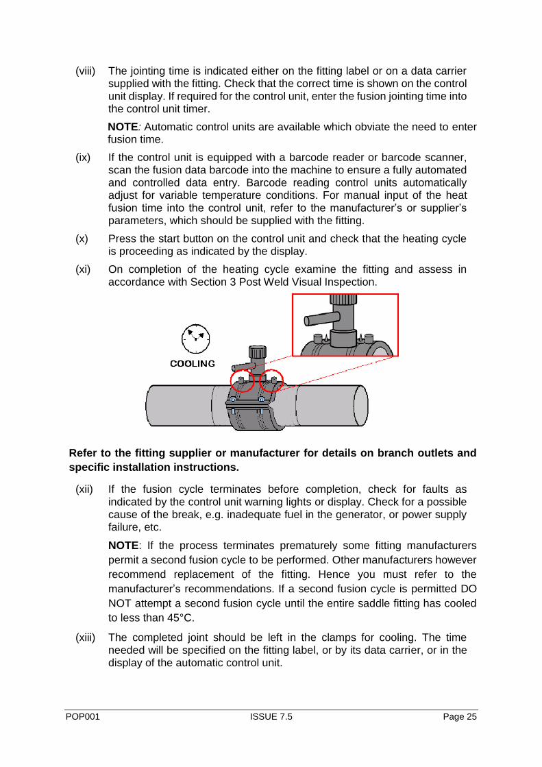
(x) Press the start button on the control unit and check that the heating cycle is proceeding as indicated by the display.
(xi) On completion of the heating cycle examine the fitting and assess in accordance with Section 3 Post Weld Visual Inspection.
Refer to the fitting supplier or manufacturer for details on branch outlets and
specific installation instructions.
(xii) If the fusion cycle terminates before completion, check for faults as indicated by the control unit warning lights or display. Check for a possible cause of the break, e.g. inadequate fuel in the generator, or power supply failure, etc.
NOTE: If the process terminates prematurely some fitting manufacturers
permit a second fusion cycle to be performed. Other manufacturers however
recommend replacement of the fitting. Hence you must refer to the
manufacturer’s recommendations. If a second fusion cycle is permitted DO
NOT attempt a second fusion cycle until the entire saddle fitting has cooled
to less than 45°C.
(xiii) The completed joint should be left in the clamps for cooling. The time needed will be specified on the fitting label, or by its data carrier, or in the display of the automatic control unit.

POP001 ISSUE 7.5 Page 26
(xiv) The connection of the service pipe to the spigot outlet should be carried out in accordance with the procedure of the appropriate section of these guidelines.
(xv) DO NOT attempt to tap the main before the completion of the required cooling cycle as specified by the supplier. Additional cooling time is recommended before tapping if the pipeline is to be field pressure tested as soon as practical – refer to manufacturers instruction.
8 JOINTING PROCEDURE - TOP LOAD ELECTROFUSION BRANCH SADDLE Top load electrofusion branch saddles are typically used for large diameter branch connections ≥ 90 mm. Applications include new installations, renovation, repair and under pressure live branch connections on existing PE mains for sizes to DN630 mm.
Typical installation instructions are detailed below:
(i) Ensure hands and tools are free from surface contaminants, such as hand cream, sun screen, detergent and surfactant used in horizontal directional drilling.
(ii) Clean pipe in the fusion area with an approved alcohol wipe as detailed above then remove the oxidised layer with a rotary or mechanical peeler.

POP001 ISSUE 7.5 Page 27
(iii) Clean pipe in the fusion zone with an approved alcohol wipe.
(iv) Mount the fitting to the pipe in accordance to the manufacturer’s instructions using the manufacturer’s topload tool. The manufacturers tools vary in the method they apply pressure to the saddle fitting – the common devices will be either mechanical, pneumatic or operate using vacuum. Regardless of the means by which pressure is applied ensure a positive contact is made between the pipe and saddle. The joint gap should not exceed 0.5 mm.
(v) Connect the terminals and apply the fusion voltage
(vi) The assembled joint must be left in the clamps during the electrofusion and manufacturer’s specified cooling period. The cooling time is typically specified on the fitting label, or by its data carrier, or in the display of the automatic control unit. Any reduction in clamping pressure, during this period, can cause joint failure.
(vii) The core should not be drilled until the time specified by the
manufacturer. Typically this can be as long as 4x the cooling time
measured from the end of the weld cycle

POP001 ISSUE 7.5 Page 28
APPENDIX A
RECORD SHEETS
Record sheets should be maintained for all equipment required for all fusion jointing
operations. The sheet should be headed:
‘SERVICING AND CALIBRATION RECORD SHEET’
Followed by:
‘ELECTROFUSION SOCKET EQUIPMENT /
ELECTROFUSION SADDLE EQUIPMENT’
(delete as appropriate)
and then the appropriate sub-title from the following list (additional record sheets may
be kept if required):
Electrofusion socket jointing:
Generators
Electrofusion control unit
Electrical safety test
Electrofusion saddle jointing:
Generators
Electrofusion control unit
Electrical safety test

POP001 ISSUE 7.5 Page 29
The information recorded on the sheet should include but not be restricted to:
• The date of servicing or maintenance.
• The name, address and telephone number of the undertaking or contractor operating the equipment.
• The name, address and telephone number of the company conducting the service or maintenance.
• The member (or members) of staff responsible for servicing or maintenance.
• The serial number of the equipment.
• The details of service and/or maintenance carried out. This should include relevant details of test equipment, procedures and/or manuals used, and relevant ambient conditions.
• The signature(s) of the member (or members) of staff responsible for the servicing or maintenance operations conducted.


