IOSR Journal of Electrical and Electronics Engineering (IOSR-JEEE) e-ISSN: 2278-1676,p-ISSN: 2320-3331, Volume 11, Issue 2 Ver. II (Mar. – Apr. 2016), PP 01-13 www.iosrjournals.org DOI: 10.9790/1676-1102020113 www.iosrjournals.org 1 | Page Electromagnetic And Thermal (Lumped Circuit) Analysis Of Internal Permanent Magnet Synchronous Machine Monika Verma 1 , Arun Kumar G 2 , Ganesh Nagarajan 3 1 M Tech, Power Electronics & Drives SELECT, VIT University, Vellore, Tamil Nadu, India 2 Asst. Professor (Sr.), SELECT, VIT University, Vellore,Tamil Nadu, India 3 Deputy Manager, CAE-Electric Machines Powertrain Engineering-CAE & TESTING, RNTBCI Pvt Ltd, India Abstract: The unique merits of internal permanent magnet synchronous machine (IPMSM) make it a good candidate for automotive industrial applications. This paper presents the design of an internal permanent magnet synchronous machine having fractional slot configuration with single layer concentrated winding arrangement. The electromagnetic analysis has been performed using finite element analysis via ANSYS Maxwell v.2014. Thereafter a lumped parameter thermal network model has been developed for thermal analysis of designed model. The validation of the IPMSM model has been carried out through a few case studies by comparing the respective results. Keywords: IPMSM, finite element analysis, ANSYS Maxwell, lumped circuit thermal network. I. Introduction There are different electrical machines that have been used in automotive application so far, like induction machines, DC machines, permanent magnet machines and switched reluctance machines. Among these, DC machines have been ruled out because of the high maintenance problems associated with its operation. The operation of switched reluctance machines are difficult to control due to which not taken under consideration for such applications. The induction machines are the most interesting machines for automobile applications up to now. However, the PMSMs are the most capable competitor with induction machines for automotive applications due to their many advantages including high efficiency, compactness, high power density, fast dynamics and high torque to inertia ratio. The Internal PMSM having additional features of mechanical robustness, flux weakening capability and high speed operation are particularly suitable for automotive applications. Different topologies of permanent magnet machines are available e.g. radial flux and axial flux PMSMs. Radial flux PMSMs are the most common due to its simplicity and its similarity with the synchronous AC motors. In this configuration, Internal PMSM exhibit better performance by providing high air gap flux density and also the PMs are protected against demagnetization and mechanical stress. Proper performance of IPMSMs depends on their optimal design and control. In this paper, an optimized design of internal permanent magnet synchronous machine has been proposed. For this, the design parameters are computed analytically and then optimized on the basis of finite element analysis using ANSYS Maxwell results. After this, thermal nodal network is obtained for thermal analysis. Finally, the model configuration is validated through a few case studies. II. Machine Model Design The internal permanent magnet synchronous machines are available in various configurations; among them the one with tangential magnet poles having single barrier structure enjoys many features including structural simplicity, mechanical robustness, good flux weakening capability and high speed range. For winding layout design, the single layer concentrated winding arrangement has been used due to following advantages: Electrical separation among the phases (which implies separate source for each phase) Physical separation among the phases (which implies a single layer winding with non-overlapped coils) Magnetic separation among the phases (which implies a null mutual inductance) A. Dimensions of rotor, stator, PM, flux barriers The desired rating parameters of the machine to be designed in this work are: Output power, P = 4 kW Base speed, = 3000 rpm Therefore, the nominal torque to be achieved should be:
Transcript
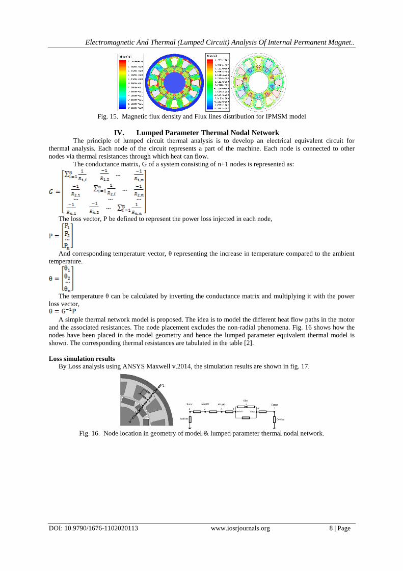
IOSR Journal of Electrical and Electronics Engineering (IOSR-JEEE)
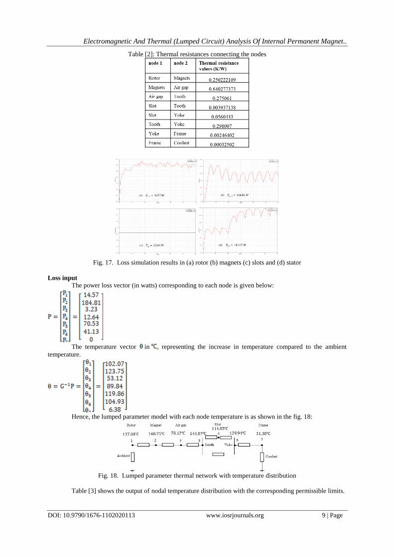
It can be seen that the temperatures of the different parts of the machine are under safe thermal limits.
V. Case Studies For Validation Of Model Configuration Here, the feasibility of proposed topology for IPMSM is discussed and different case studies are carried
out to check the performance of the machine with the selected configuration. Thus the designed machine model
is validated with the help of the respective results.
F. Case study (I): Efficiency test
In order to check efficiency, the stator configuration of IPMSM is examined. Here, testing of the
designed model is done with both types of concentrated and distributed winding configuration. The losses and
efficiencies in both models are compared. Table [4] gives the comparison of the results for the designed model
and the test model. It is to be noted that the test model is having same optimized dimensions of that of the
designed model except the winding arrangement, which is distributed in this case.
Hence it is proved using this test that using concentrated winding increases the efficiency in low speed
region, where copper loss is more prominent than core loss.
Table [4] Test results for comparison of losses and efficiency
G. Case study (II): Test for noise and vibration
The problems of vibration and noise production in the machine mainly arise due to the torque ripple
and cogging torque. Fractional pitch winding configuration is recommended so as to obtain minimum cogging
torque. With this, the torque ripples are also reduced, thereby decreasing the problems of vibrations in the
machine. So, for proving this fact the test model is designed with full pitch winding configuration with 24 slots,
8 pole combination. The simulations are done to compare the results of torque ripple and cogging torque value
of both the models.
Electromagnetic And Thermal (Lumped Circuit) Analysis Of Internal Permanent Magnet..
The core losses occur in the machine mainly due to the improper selection of the core material.
Therefore, an appropriate choice of material which has a narrower hysteresis loop and the ability to be made into
very thin laminations is desired. Non-oriented (N.O.) silicon sheet steel is the most common choice which is
made for the machine model used in this work. A simple test is carried out by taking a test core material which
exhibit wider hysteresis loop. Thus, the core losses are compared for two models to check the performance of
the machine with two different materials.
The machine using core material with narrower hysteresis loop possess lesser core loss and more
torque output whereas the performance with wider hysteresis core material lesser torque is obtained with more
losses in the core. Therefore, this test gives favorable results for the machine performance.
J. Case study (V): Performance of motor with different permanent magnets
The purpose of permanent magnets in the IPMSM machines is to provide the necessary rotor flux
which has to be stationary with respect to stator mmf to produce the steady state torque. As the necessary torque
produced by the motor has been the main designing criteria in this work, hence the torque produced by the
machine with different permanent magnets are compared by this test. Also the flux linkages are compared with
different magnets. Table [8] shows the flux lines plots and torque simulation results produced by the model with
different magnets in the rotor.
Table [8] Test results for the model with different magnets
As can be observed from the test results, the best performance is given by the NdFeB magnets which is
used in this thesis work. The worst performance is given by the ferrite magnets if would have been used in the
designed model. However, SmCo and Alnico magnets are producing almost the same torque and flux linkages.
The Samarium Cobalt magnets are costlier than NdFeB magnets. And Alnico magnets despite being oldest
commercially available magnets have relatively low magnetic values because their ease of demagnetization.
Hence, NdFeB magnets are the recommended magnets for the proposed topology of the IPMSM model.
VI. Conclusion
IPM technology is taking several industries by storm. It is compact, light, efficient, reliable and can be
used in divert craft system. In this paper, an optimal and accurate design of internal permanent magnet
synchronous machine with single layer, fractional slot concentrated winding and single flux barrier rotor
structure has been proposed.
The number of turns in the stator winding, angle of excitation, slot structure, stack length, positioning
& dimensioning of permanent magnet and flux barrier structures in the motor using Finite Element Analysis has
been chosen as the optimization criteria. For this purpose, the analytical model is designed and hence analyzed
to get the best performance out of the optimized design. Thereafter, a lumped parameter thermal nodal network
is designed to perform thermal analysis of the model. A few case studies were performed over the machine
configuration to check and validate the model configuration. Comparison of results show the validity of
analytical design.
References [1]. “Electric Motor Drive Selection Issues for HEV Propulsion Systems: A Comparative Study” M. Zeraoulia1, Student Member,
IEEE, M.E.H. Benbouzid1, Senior Member, IEEE, and D. Diallo2, Member, IEEE 1Laboratoire d‟Ingénierie Mécanique et
Electrique (LIME), IUT of Brest, University of Western Brittany Rue de Kergoat – BP 93169, 29231 Brest Cedex 3, France
[2]. “Sizing of Electrical Machines”, PEBN #9 (26 Sep 2008), W.L. Soong, School of Electrical and Electronic Engineering, University of Adelaide, Australia, [email protected]
[3]. “Use of the star of slots in designing fractional-slot single-layer synchronous motors”, N. Bianchi and M. Dai Pr!e
[4]. ANSYS Maxwell 2D Field Simulator v14 User‟s Guide, ANSYS Maxwell V16 Training Manual. [5]. “Design of a permanent magnet synchronous machine for the hybrid electric vehicle”, World academy of Science, engineering and
[6]. Design and Analysis of a Fractional-Slot Concentrated-Wound PM-Assisted Reluctance Motor, LUIGI MARINO, , KTH royal
institute of technology, electrical engineering. [7]. “Lumped Parameter Thermal Modelling of Electric Machines”, Analysis of an Interior Permanent Magnet Synchronous Machine
for Vehicle Applications, Bjorn Andersson, division of electric power engineering, Chalmers university of technology, Goteborg,
Sweden. [8]. Thermal Network Modeling Handbook, K&K Associates, Version 97.003, Nation Aeronautics and Space Administration. 1976.
[9]. “Challenges and solutions for IPMSM to be used as a next generation electrical machine”, Shah Asifur Rahman, Proceedings of the
2011 international conference on industrial engineering and operations management, kuala lumpur, Malaysia, January 22-24, 2011. [10]. IPM technology, by Atlas Copco, https://www.youtube.com/watch?v=1bV8W5DZCIQ&spfreload=10