20
Western Washington University ‐ Electronics Engineering Technology ETec471 Project Description Outline Stephen van Someren Gréve 11/12/2010
Western Washington University ‐ Electronics Engineering Technology
ETec471 Project Description Outline Stephen van Someren Gréve
11/12/2010

1
Table of contents
Introduction
Hardware Description‐
Figure 1: Product Dimensions The Central Processor
The Audio Processor Table 1: VLSI Speeds
The Wireless Module
Table 2: Supported Com Speeds The LCD The Keypad and Dial The Power Supply Figure 2: System Diagram
Table 3: PSoC Pins required for Wifly GSX Table 4: PSoC Pins required for VLSI VS1053b
Table 5: PSoC Pins required for HD44780
Table 6: PSoC Pins required for User Input
Software Description‐
Init_Wifly Generate_Webpage Playback

2
Update LCD Look_For_Input
User Interface‐
Figure 3: Idle State Webpage
Figure 4: Analog State Webpage
Figure 5: Wireless State Webpage (music playing)
Figure 6: Wireless State Webpage (music paused, MP3 tags scrolling)
Figure 7: Configuration State Webpage
Figure 8: Idle State Screen
Figure 9: Analog State Screen
Figure 10: Wireless State Screen (music playing)
Figure 11: Wireless State Screen (music paused, MP3 tags scrolling)
Figure 12: Configuration State Screen
Figure 13: Configuration State Screen (cont)
Figure 14: UI State Diagram
Figure 15: UI State Diagram(Cont)
Communications
Development Plan
Table 7: Development Schedule Required Development Hardware and Software Demonstration Prototype and Materials: Sustainability Design Issues
Electrical Specifications Project specifications:

3
Power requirements Table 8: Preliminary 3.3 V Spec Sheet Table 9: Preliminary 5 V Spec Sheet Table 10: Size Restrictions

4
Introduction – I propose to build a wireless, web enabled mp3 audio playback device, the Wifi Hifi, which will stream music from other network connected devices such as PCs as well as being able to serve an interactive web control page using IEEE 802.11b transceiver. The system will incorporate an LCD screen to indicate what is playing or what source is connected. The device will be the central receiver for a high fidelity home audio amplifier.
Hardware Description– The Wifi Hifi final product will be integrated into a home audio receiver/amplifier. The device will have a 6‐pole power connector which connects to the Hammond 546‐272JX transformer, an SMA connector to allow for an external antenna, a 3‐pole terminal for the line level audio out, a 3‐pole terminal for the line level audio in that connects to the stereo jack on the amplifier, as well as a port for connecting the four button keypad and a port for connecting the LCD screen from the amplifier. The maximum dimension for this device will be 12x8.75x2.5 inches refer to table 9.
Figure 1: Product Dimensions The Central Processor The heart of this project will be a Cypress PSoC 5 CY8C53 32‐bit microcontroller (refer to figure 2). The PSoC 5, which has a 256 KB of flash program memory and 64 KB SRAM memory and 2k

5
EEPROM it will operate at 80MHz. The PSoC 5 has resources for SPI, SCI, SDI, and UART communication protocols to communicate with the VSLI MP3 audio decoder and the Wifly GSX wireless module as well as a plethora of IO to interface with the LCD, button matrix, and rotary position encoder used for volume control. It can be run at a variety of voltages from .5 to 5.5 V using an on chip switch mode DC‐DC converter, I will use it at 3.3 V under typical conditions it consumes 2mA. The PSoC 5 has up to 62 GPIOs, which can be routed as either digital or analog, 8 SIOs, and 2 USBIOs. I will be using 27 GPIO, 3 SIO, and 1 clock output. The correlation between PSoC pins and other device pins is shown in figure 2.

6
Figure 2: System Diagram
Key: Red indicates that the signal is transmitted by a non PSoC device, green represent bi‐directional or AC inputs, and blue represents signals received by devices other than the PSoC.

7
The Audio Processor The audio processor, which processes raw MP3 data received through the wireless module and converts it to line level audio, is the VLSI VS1053b. It features 16 KB of instruction RAM and 0.5+ KB of data RAM for user programs. It operates at 13MHz and requires an external 13MHz crystal to set speed. It consumes a maximum current of 60 mA. The pins required to communicate effectively with the device are shown in table 3. PSoC Pin Number
PSoC Pin Type
Pin Number
Pins connected to PSoC from the Audio Processor Module using SDI:
5[0] GPIO 3 xRESET (active low reset) 5[1] GPIO 8 DREQ (data request) 5[3] GPIO 13 XDCS/BSYNC 15[0] MHzXout 28 SCLK (SPI Clock) 12[4] SIO 29 SI Table 3: PSoC Pins required for VLSI VS1053b For detailed information: http://www.vlsi.fi/fileadmin/datasheets/vlsi/vs1053.pdf The Wireless Module The wireless module which receives data over the home infrastructure mode wireless network and sends data to and from the user is the Wifly GSX. It has 8 Mbit flash memory, 128 KB RAM available, and 2KB battery backed memory. It operates at a frequency of 1Mbps if connected through SDI. It consumes a maximum current of 210mA at a voltage of 3.3 V but only 100mA under normal usage conditions and as little as 4 uA when in sleep mode. For pins connected to the Wifly GSX refer to table 4. The Wifly GSX has a range up 330 feet or 100 meters and has a typical receive sensitivity of ‐85dBm, and a class 1 output level, +18dBm. It is capable of transmitting on one of 14 channels in 2402~2480MHz RF range with 5MHz intervals between channels. Capable of speeds between 1‐11 Mbps for 802.11b and 6‐54 Mbps for 802.11g by using OFDM as well as DSSS(CCK‐11, CCK‐5.5, DQPSK‐2, DBPSK‐1) modulation schemes. It is FCC, IC, and CE certified.
PSoC 5 Pin
PSoC Pin Type
Pin Number
Pins connected to PSoC from the Wireless Module to use SDI :
6[0] GPIO 5 RESET pull‐up 6[1] GPIO 9 FORCE_AWAKE (31us min pulse) 6[2] GPIO 10 UART RTS/ GPIO 13 6[3] GPIO 11 UART CTS/ GPIO 12 12[5] SIO 12 UART RX 12[6] SIO 13 UART TX

8
6[4] GPIO 24 GPIO 9/ AD HOC/ Factory Reset 6[5] GPIO 27 GPIO 6/ Association Status 6[6] GPIO 28 GPIO 5/ Data Xfer Status 6[7] GPIO 29 GPIO 4/ Connection Status Table 4: PSoC Pins required for Wifly GSX For detailed information: http://www.rovingnetworks.com/documents/rn‐131‐ds.pdf
http://www.rovingnetworks.com/documents/WiFlyGSX‐um.pdf The LCD The Wifi Hifi has a 20x4 backlit character LCD. The LCD has a supply current of 1.5mA max and a backlight current of 180mA max. The LCD requires 10 of the PSoC’s IO pins and utilizes the common ST7066/HD44780 parallel interface (refer to Table 5). It’s dimensions are 98.0×60.0×14.0mm or approximately 3.858” x2.362” x0.551”. It is a 5 volt system fortunately the PSoC 5 is 5 volt tolerant. Table 5 shows which relevant pins will be used. PSoC Pin Number PSoC Pin Type Pin Number Pins connected to PSoC from the LCD: 15[4], 15[5], 2[0‐7] GPIO 4‐14 HD44780 parallel interface
Table 5: PSoC Pins required for HD44780
For detailed information: http://www.satistronics.com/myfiles/file/LCD/RT204‐1.pdf The Keypad and Dial I will use a four button capsense touchpad in conjunction with a volume knob connected to a rotary position encoder which I will use as input when a web enabled device is not available, the four capsense buttons will connect to four pins of the PSoC 5 and the CUI AMT‐103 universal optical rotary encoder connects with 3 pins to PSoC 5. I will the Cypress capsense library to ensure proper debouncing and button reading. The CUI AMT‐103 universal optical rotary encoder is a 5 volts system fortunately the PSoC 5 can handle these levels. PSoC Pin Number PSoC Pin Type Pin Number Pins connected to PSoC from the LCD: 4[0‐4] GPIO 1‐4 Four button capsense keypad Table 6: PSoC pin required for four button capsense touchpad PSoC Pin Number PSoC Pin Type Pin Number Pins connected to PSoC from the CUI AMT‐1034[4] GPIO 1 B Channel 4[5] GPIO 3 A Channel 4[6] GPIO 4 Index Output Table 7: PSoC pins required for rotary encoder. For more information: http://datasheet.octopart.com/AMT103‐V‐CUI‐datasheet‐143802.pdf
9
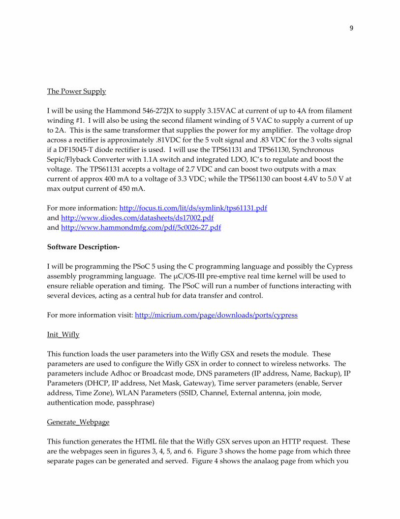
The Power Supply I will be using the Hammond 546‐272JX to supply 3.15VAC at current of up to 4A from filament winding #1. I will also be using the second filament winding of 5 VAC to supply a current of up to 2A. This is the same transformer that supplies the power for my amplifier. The voltage drop across a rectifier is approximately .81VDC for the 5 volt signal and .83 VDC for the 3 volts signal if a DF15045‐T diode rectifier is used. I will use the TPS61131 and TPS61130, Synchronous Sepic/Flyback Converter with 1.1A switch and integrated LDO, IC’s to regulate and boost the voltage. The TPS61131 accepts a voltage of 2.7 VDC and can boost two outputs with a max current of approx 400 mA to a voltage of 3.3 VDC; while the TPS61130 can boost 4.4V to 5.0 V at max output current of 450 mA. For more information: http://focus.ti.com/lit/ds/symlink/tps61131.pdf and http://www.diodes.com/datasheets/ds17002.pdf and http://www.hammondmfg.com/pdf/5c0026‐27.pdf Software Description‐ I will be programming the PSoC 5 using the C programming language and possibly the Cypress assembly programming language. The μC/OS‐III pre‐emptive real time kernel will be used to ensure reliable operation and timing. The PSoC will run a number of functions interacting with several devices, acting as a central hub for data transfer and control. For more information visit: http://micrium.com/page/downloads/ports/cypress Init_Wifly This function loads the user parameters into the Wifly GSX and resets the module. These parameters are used to configure the Wifly GSX in order to connect to wireless networks. The parameters include Adhoc or Broadcast mode, DNS parameters (IP address, Name, Backup), IP Parameters (DHCP, IP address, Net Mask, Gateway), Time server parameters (enable, Server address, Time Zone), WLAN Parameters (SSID, Channel, External antenna, join mode, authentication mode, passphrase) Generate_Webpage This function generates the HTML file that the Wifly GSX serves upon an HTTP request. These are the webpages seen in figures 3, 4, 5, and 6. Figure 3 shows the home page from which three separate pages can be generated and served. Figure 4 shows the analaog page from which you
10
can control the volume of the amplifier and return to the home page from. Figure 5 and 6 shows the Wireless State webpage from which volume as well as playback controls and file selection may be accessed. The information about which song is playing is identical to what is being display on the LCD screen at that moment. Figure 7 shows the configuration page from which the user can configure the amplifier wireless settings.
Please Make a Choice:
Analog Connected
Volume:
Figure 3: Idle State Webpage Figure 4: Analog State Webpage
Wireless Connected
Volume:
Currently Paused:
WIRELESS 03:56 01:23
HE DISTANCE/CAKE/2/F
Wireless Connected
Volume:
Currently Playing:
WIRELESS 03:56 01:23
THE DISTANCE/CAKE/2/
Figure 5: Wireless State Webpage (music playing) Figure 6: Wireless State Webpage (music paused, MP3 tags scrolling)

11
Playback Configuration Mode:
Wireless mode: Adhoc
Broadcast
IP Parameters:
DHCP On
OFF
IP Address:
Netmask:
Default Gateway:
Autojoin On
OFF
Authentication Mode:
Passphrase:
DNS and Other Setting:
IP Address:
Name:
Backup:
This function loads data from the Wifly GSX into a buffer and transfers the front of the buffer into the VLSI audio decoder. The turn dial controls the VSLI’s internal volume. Button 2 pauses playback while button 3 and button 4 skip to the next and previous song respectively. Look_For_Input This is function checks the four button keypad and the rotary position encoder for changes. This module also implements debouncing to accurately read button presses. This function is called to receive user input.
Figure 7: Config Webpage

12
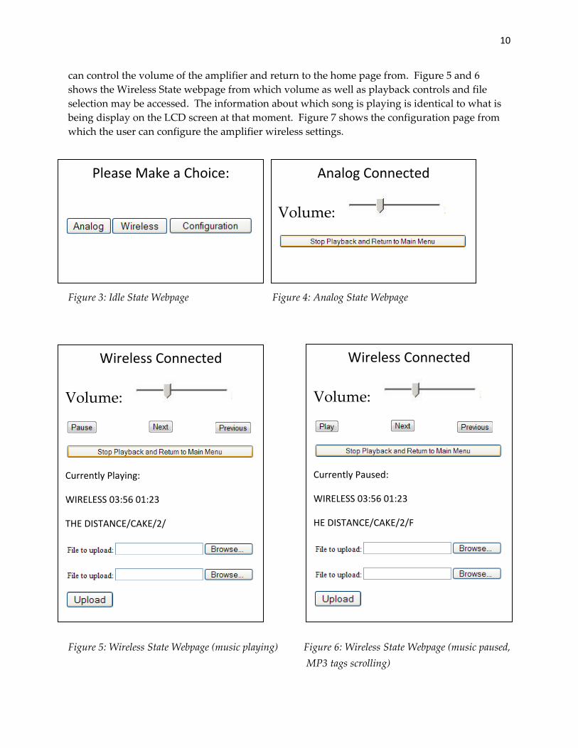
Update_LCD This function is used pass information to the LCD. It has preset layouts into which data can be passed. Figure 8 represents the home screen this is the first screen that the user sees. Figure 9 is the analog screen; it has the option to go back to the home menu. Figure 10 is what the user sees after choosing wireless and starting a song, note that figure 11 shows the scrolling used to display full song data. Figure 12 is a display of the configuration menu since the configuration menu has settings that need more than four button to individually control each parameter efficiently the button become more generic functioning to move the user through the menu as seen on screen 13 with the volume knob functioning to set alpha‐numerical values.
P L E A S E M A K E A C H O I C E 1 - A N A L O G 2 - W I R E L E S S 3 - C O N F I G U R A T I O N Figure 8: Idle State Screen
A N A L O G 1 - M E N U Figure 9: Analog State Screen
W I R E L E S S 0 3 : 5 6 0 1 : 2 3T H E D I S T A N C E / C A K E / 2 /1 - P A U S E 2 - N E X T 3 - P R E V I O U S Figure 10: Wireless State Screen (music playing)
W I R E L E S S 0 3 : 5 6 0 1 : 2 3H E D I S T A N C E / C A K E / 2 / F
13
1 - P L A Y 2 - N E X T 3 - P R E V I O U S Figure 11: Wireless State Screen (music paused, MP3 tags scrolling)
C O N F I G U R A T I O N N E T W O R K M O D E I P P A R A M E T E R S 1 - 2 - 3 - 4 - Figure 12: Configuration State Screen
C O N F I G U R A T I O N I P P A R A M E T E R W L A N 1 - 2 - 3 - 4 - Figure 13: Configuration State Screen (cont)
User Interface‐
The Wifi Hifi utilizes two forms of user interaction, one through front controls including four buttons and a dial and another which is accessible through a web browser. The web interface allows for the sharing of files with the Wifi Hifi. The flow diagram for the typical user interface is given in figure 14, with figure 15 representing the configuration menu.

14
Figure 14: UI State Diagram
BUTTON 1: SOURCES
BUTTON 1: ANALOG
RESET
BUTTON 4: PREV SONG
Initialize and Authenticate
On (Idle)
Generate Webpage for Analog Generate Webpage
for Digital
BUTTON 2: WIRELESS
Update LCD Display Enable Analog Audio Out
Update LCD Display Enable MP3 Audio
OutBUTTON 2: PAUSE/PLAY
BUTTON 3: NEXT SONG
Play Next Song
Pause Playback
Play Previous Song
Generate Webpage for Idle
BUTTON 3: CONFIG
Continued on Next Page

15
Figure 15: UI State Diagram(Cont)
IP Parameters
WLAN
DHCP
Network Mode
Ad Hoc Mode (Configuration Only)
Broadcast Mode
IP address
Net Mask 0‐255 0‐255 0‐255 0‐255
0‐255 0‐255 0‐255 0‐255
On
SSID Scan ASCII 0‐128
Channel Scan 1‐14
Auto Join On Off
OnAuthentication mode
0‐255 0‐255 0‐255 0‐255Default Gateway
Off
DNS and Other Settings
IP address 0‐255 0‐255 0‐255
Name ASCII 0‐128
ASCII 0‐128Backup
0‐255
Passphrase

16
Communications The Wifi Hifi will receive music at line level of 1.5 volts through a three pole terminal, a three pole terminals that connects to the input of the amplifier, as well as receiving and sending information for configuration and control over IEEE 802.11b‐1999 standard 2.4GHz through an antenna connected to U.FL connector.
Development Plan
Tasks Quarter Week
Begin interfacing with VSLI VS1053b Winter 2011 1,2 Initialization and configuration of Wifly GSX 3,4 LCD, dial, button matrix configuration 5,6 HTML module 7,8 User Interface module 9 Get ready for the final 10 Combination of software modules Spring 2011 1,2 Hardware review 3 Testing everything works together 4,5 Software system presentation 6 Final adjustment 7 Final testing 8 Code review 9 Final Presentation 10
Table 8: Development Schedule Required Development Hardware and Software I will develop this project in the Ross Engineering Technology lab ET340 on Western Washington University’s campus as well as from my home. The laboratory is fully equipped with the necessary test equipment, including an oscilloscope, a logic analyzer, and I also have a home computer from which I can program. I would like to use the PSoC CY8CKIT‐001 as a development board for the Wifi Hifi, I need access to PSoC Creator 1.0 Beta 5 at the lab in order to debug my code, and it is available for free from cypress.com. I may also need an HTML editor to check my HTML code. Table 8 shows a timeline of how I plan to develop the project over the next year.

17
Demonstration Prototype and Materials: I will demonstrate my standalone prototype incased inside the amplifier receiver, I will use soldering and possibly a reflow oven to construct a PCB populated with my components. I will connect the PCB to the amplifier receiver through screw terminals. In order to demonstrate my project I will need a PC a wireless network and appropriate power terminal. Sustainability Design Issues The Wifi Hifi will be fully RoHS compliant however the amplifier it is connected to may not be. The power required to operate the Wifi Hifi is minimized by using low voltage components and putting them to sleep when not in use. Electrical Specifications Project specifications: Wifly GSX: FCC ID U3O‐G2M5477 Part 15.247 IC(Canada) RSS‐210 CE EU ID # 0681 REG U9M20901‐1000‐C RADIO EN 300328 V1.7.1 (10/2006) EMC EN 301489‐1 V1.8.1 (04/2008), EN 301489‐17 V1.3.2 (04/2008) SAFETY EN 60950‐1:2001+A11:2004 RoHs Compliant 2402 ~2480MHz 802.11b compatibility : DSSS(CCK‐11, CCK‐5.5, DQPSK‐2, DBPSK‐1) 802.11g : OFDM (default) Channel intervals 5MHz Channels 1‐14 Transmission rate(over the air) 1‐11Mbps for 802.11b/6‐54Mbps for 802.11g Receive sensitivity ‐85dBm typ. Output level (Class 1) +18dBm Maximum RF input to U.FL connector 10 dBm Audio Input/Output Levels DAC Resolution 18 bits Total Harmonic Distortion THD 0.07 % Third Harmonic Distortion 0.02 % Dynamic Range (DAC unmuted, A‐weighted) IDR 100 dB S/N Ratio (full scale signal) SNR 94 dB Interchannel Isolation (Cross Talk), 600Ω + GBUF 80 dB Interchannel Isolation (Cross Talk), 30Ω + GBUF 53 dB Interchannel Gain Mismatch Min: ‐0.5 dB Max: 0.5 dB
18
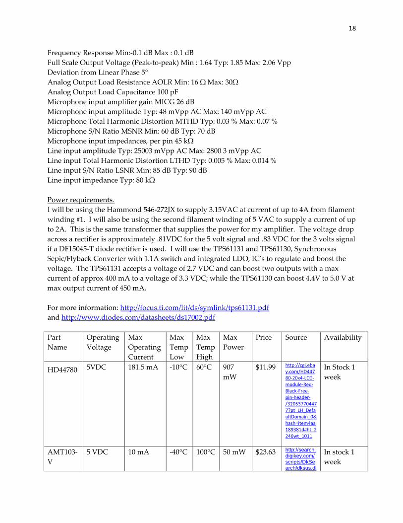
Frequency Response Min:‐0.1 dB Max : 0.1 dB Full Scale Output Voltage (Peak‐to‐peak) Min : 1.64 Typ: 1.85 Max: 2.06 Vpp Deviation from Linear Phase 5° Analog Output Load Resistance AOLR Min: 16 Ω Max: 30Ω Analog Output Load Capacitance 100 pF Microphone input amplifier gain MICG 26 dB Microphone input amplitude Typ: 48 mVpp AC Max: 140 mVpp AC Microphone Total Harmonic Distortion MTHD Typ: 0.03 % Max: 0.07 % Microphone S/N Ratio MSNR Min: 60 dB Typ: 70 dB Microphone input impedances, per pin 45 kΩ Line input amplitude Typ: 25003 mVpp AC Max: 2800 3 mVpp AC Line input Total Harmonic Distortion LTHD Typ: 0.005 % Max: 0.014 % Line input S/N Ratio LSNR Min: 85 dB Typ: 90 dB Line input impedance Typ: 80 kΩ Power requirements. I will be using the Hammond 546‐272JX to supply 3.15VAC at current of up to 4A from filament winding #1. I will also be using the second filament winding of 5 VAC to supply a current of up to 2A. This is the same transformer that supplies the power for my amplifier. The voltage drop across a rectifier is approximately .81VDC for the 5 volt signal and .83 VDC for the 3 volts signal if a DF15045‐T diode rectifier is used. I will use the TPS61131 and TPS61130, Synchronous Sepic/Flyback Converter with 1.1A switch and integrated LDO, IC’s to regulate and boost the voltage. The TPS61131 accepts a voltage of 2.7 VDC and can boost two outputs with a max current of approx 400 mA to a voltage of 3.3 VDC; while the TPS61130 can boost 4.4V to 5.0 V at max output current of 450 mA. For more information: http://focus.ti.com/lit/ds/symlink/tps61131.pdf and http://www.diodes.com/datasheets/ds17002.pdf Part Name
Operating Voltage
Max Operating Current
Max Temp Low
Max Temp High
Max Power
Price Source Availability
HD44780
5VDC 181.5 mA ‐10°C 60°C 907 mW
$11.99 http://cgi.ebay.com/HD44780‐20x4‐LCD‐module‐Red‐Black‐Free‐pin‐header‐/320537704477?pt=LH_DefaultDomain_0&hash=item4aa189381d#ht_2246wt_1011
In Stock 1 week
AMT103‐V
5 VDC 10 mA ‐40°C 100°C 50 mW $23.63 http://search.digikey.com/scripts/DkSearch/dksus.dl
In stock 1 week

19
l?Cat=1966131&k=AMT103
Total Power
957 mW
Table 9: Preliminary 5 V Spec Sheet Part Name
Operating Voltage
Max Operating Current
Max Temp Low
Max Temp High
Max Power
Price Source Availability
Wifly GSX
3.3VDC 210mA 0°C 70°C 693 mW
$49.95 http://www.sparkfun.com/products/10004
In Stock 1 week
VSLI VS1053b
3.3VDC 60mA ‐30°C 85°C 198 mW
$19.95 http://www.sparkfun.com/products/8892
In Stock 1 week
PSOC CY8C55
3.3VDC 2mA ‐55°C 100°C 6.6mW
$5.00 http://www.cypress.com/?id=2218&source=header
Already Purchased
Discreet Components
3.3VDC‐5VDC
n/a n/a
n/a
n/a
~$10 In stock at lab
Already Purchased
Total Power
897.6 MW
Total cost
$120.52
Table 10: Preliminary 3.3 V Spec Sheet PCB Max Size Limits Distance (inches)Length 12” Width 8.75” Height 2.5” Table 11: Size Restrictions


