A FINITE ELEMENT TEST BED FOR DEVELOPMENT OF FEEDBACK CONTROL LAWS FOR ELECTROSTATIC MEMS by BALASAHEB DNYANDEO KAWADE, B.E. A THESIS IN MECHANICAL ENGINEERING Submitted to the Graduate Faculty of Texas Tech University in Partial Fulfillment of the Requirements for the Degree of MASTER OF SCIENCE IN MECHANICAL ENGINEERING Approved Jordan Berg Chairperson of the Committee Tim Dallas Alexander Idesman Accepted John Borrelli Dean of the Graduate School December, 2005
Transcript
A FINITE ELEMENT TEST BED FOR DEVELOPMENT OF
FEEDBACK CONTROL LAWS FOR
ELECTROSTATIC MEMS
by
BALASAHEB DNYANDEO KAWADE, B.E.
A THESIS
IN
MECHANICAL ENGINEERING
Submitted to the Graduate Faculty of Texas Tech University in
Partial Fulfillment of the Requirements for
the Degree of
MASTER OF SCIENCE
IN
MECHANICAL ENGINEERING
Approved
Jordan Berg Chairperson of the Committee
Tim Dallas
Alexander Idesman
Accepted
John Borrelli Dean of the Graduate School
December, 2005
ACKNOWLEDGEMENTS
During the course of this project and the research, I have acquired an
impressive indebtedness. It is impossible to acknowledge everyone who has
contributed to this research, but I wish to express my sincere gratitude to several
people in particular. I am thankful to my thesis committee members Dr. Jordan
Berg, Dr. Tim Dallas and Dr. Alexander Idesman for their constant support and
advice throughout this project. My sincere thanks are to Dr. Sanjeeva
Maithriapala whose cooperation in this work cannot be expressed in words.
I thank Dr. Berg for his guidance and willingness to help me in this work.
His motivation in this project not only made it successful but will also be helpful
to my career. The guidance of Dr. Dallas was extremely valuable throughout my
studies in MEMS and research at Texas Tech University. Graduate coursework in
MEMS under guidance of Dr. Dallas was really helpful to start my career in finite
element analysis and the use of ANSYS. Graduate coursework with Dr.
Alexander Idesman was a wonderful opportunity to learn finite element
fundamentals. I am thankful to him for his support to advance my career in FEA.
Financial support provided by Dr. Berg is gratefully acknowledged. I am
extremely grateful to my parents, brother, sister and Mr. Sanjay Zaware, who
gave me an inspiration and strength for my higher studies. I am thankful to Mr.
Ramchandra Deshmukh and Mr. Chirag Bhojani who motivated me for my
higher studies. I am highly indebted to Vijay, Teju, Manish, Amol and other
friends in India who always supported my decesions. Last but not the least, I am
highly indebted to my friends in the Lubbock whom with I shared enjoyable
moments of my life.
ii
To Aai – Dada
iii
CONTENTS
ACKNOWLEDGEMENTS............................................................................................. iii
A PREREQUISITES AND SETUP REQUIREMENTS FOR MACROS.................................................................................................................. 67
B APDL MACRO FOR STATIC FEEDBACK CONTROL FOR PISTON MICROACTUATOR...................................................................... 70
C APDL MACRO FOR DYNAMIC FEEDBACK CONTROL FOR PISTON MICROACTUATOR................................................. 85
D APDL MACRO FOR STATIC FEEDBACK CONTROL FOR PISTON MICROACTUATOR WITH PARASITIC EFFECTS................................................................................................................... 93
E APDL MACRO FOR DYNAMIC FEEDBACK CONTROL FOR PISTON MICROACTUATOR WITH PARASITIC EFFECTS .......................................................................................... 106
v
F APDL MACRO FOR STATIC FEEDBACK CONTROL FOR BREATHING MODE MICROACTUATOR............................................. 119
G APDL MACRO FOR DYNAMIC FEEDBACK CONTROL FOR BREATHING MODE MICROACTUATOR............................................................................................. 140
H APDL MACRO FOR STATIC FEEDBACK CONTROL FOR INTEGARTED CHARGE AND POSITION SENSOR.................................................................................................................. 161
I APDL MACRO FOR STATIC FEEDBACK CONTROL FOR RF MEMS SWITCH (BOTH ENDS FIXED BEAM)................................. 174
J JOURNAL AND CONFERENCE PUBLICATIONS WHERE THIS WORK IS UITLIZED .................................................................. 188
vi
ABSTRACT
This project presents the ANSYS simulation techniques for an
electrostatically‐actuated MEMS device incorporating feedback control laws. The
electrostatic MEMS device consists of a movable electrode, suspended on
flexible, elastic structures, and one or more fixed drive electrodes. Nonlinear
feedback control laws are simulated in ANSYS multi‐physics solver and a
transducer element. ANSYS multi‐physics solver is limited for these types of
simulations. ANSYS doesn’t support multiframe restart and the combined circuit
and electrostatic analysis are incompatible. This work presents simulation
techniques based on numerical methods to circumvent these limitations. The
proposed technique eliminates the circuit elements from the model, and instead
propagates the associated states in an APDL macro. ANSYS auto time stepping
method is not applicable for closed‐loop feedback control systems because loads
are calculated at each step based on simulation output at the previous step. An
adaptive step size Runge‐Kutta integration routine is incorporated within APDL
macro to develop an efficient simulation technique. The simulation efficiency of
the static closed loop feedback control systems is increased by a factor more than
100. However, a dynamic closed loop feedback control systems exhibits only a
brief initial transient, and then does not permit further step size increases. To
increase the simulation efficiency of such systems, the adaptation logic is turned
off once the step size stabilizes. Simulation results for representative MEMS
devices including a one‐DOF piston microactuator and a two‐DOF
rotating/translating microactuator demonstrate the efficiency of these simulation
techniques.
vii
LIST OF FIGURES
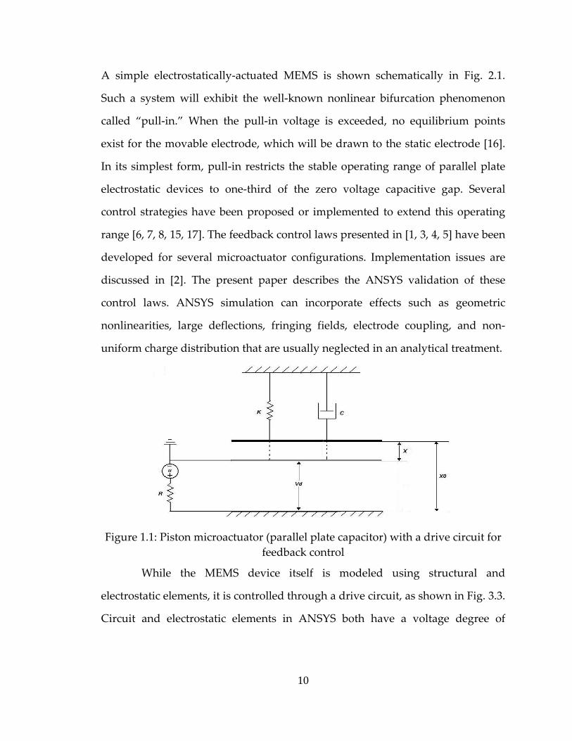
2.1 Piston microactuator (parallel plate capacitor) with a drive circuit for feedback control ........................................................................................... 10
2.3 Micromirror model and driving circuit schematic........................................ 15
2.4 Flow chart of implementation of Runge‐Kutta adaptive step size integration for feedback control transient simulation in ANSYS ............... 17
2.5 Static feedback control for a piston microactuator (Multi‐physics analysis): Step Size ............................................................................................. 18
2.6 Static feedback control for a piston microactuator (Multi‐physics analysis): Gap ..................................................................................................... 19
2.7 Static feedback control for a piston microactuator (Multi‐physics analysis): Gap ..................................................................................................... 19
2.8 Dynamic feedback control for a piston microactuator (Multi‐physics analysis): Time step size ..................................................................... 20
2.9 Dynamic feedback control for a piston microactuator (Multi‐physics analysis): Gap ....................................................................................... 20
2.10 Dynamic feedback control for a piston microactuator (Multi‐physics analysis): Charge.................................................................................. 21
2.11 Dynamic feedback control for a piston microactuator (TRANS126): Gap and Step size............................................................................................... 22
2.12 Static and Dynamic feedback control for breathing mode microactuator (Multi‐physics analysis): Time step size ............................... 22
2.13 Static and Dynamic feedback control for breathing mode microactuator (Multi‐physics analysis): C. M. Gap ...................................... 23
2.14 Static and Dynamic feedback control for breathing mode microactuator (Multi‐physics analysis): Angle of tilt (Radians) ................. 23
3.1 Parallel plate capacitor with a control circuit ................................................ 28
viii
3.2 Static feedback control law simulation for the parallel plate capacitor. (a) Time Step Size vs Time (b) Gap vs Time ................................ 30
3.3 Static feedback control law simulation for the parallel plate capacitor. (a) Control Voltage vs Time (b) Charge vs Time......................... 31
3.4 Dynamic feedback control law simulation for the parallel plate capacitor, Gap vs Time...................................................................................... 32
3.5 Dynamic feedback control law simulation for the parallel plate capacitor (a) Control Voltage vs Time (b) Charge vs Time.......................... 33
3.6 Parallel plate capacitor with a parasitic conductor and a control circuit ................................................................................................................... 34
3.7 Static feedback control law simulation for a parallel plate capacitor with a parasitic conductor. (a) Time step size vs Time (b) Gap vs Time ..................................................................................................................... 35
3.8 Static feedback control law simulation for a parallel plate capacitor with a parasitic conductor. (a) Voltages vs Time (b) Charges vs Time ..................................................................................................................... 36
3.9 Dynamic feedback control law simulation for a parallel plate capacitor with a parasitic conductor, Time step Size vs Time..................... 37
3.10 Dynamic feedback control law simulation for the parallel plate capacitor with a parasitic conductor. (a) Gap vs Time (b) Voltages vs Time ................................................................................................................ 38
3.11 Dynamic feedback control law simulation for the parallel plate capacitor with a parasitic conductor, Charges vs Time................................ 39
3.12 Breathing mode microactuator. (a) Schematic digram of a microactuator with control circuits (b) ANSYS model................................. 40
3.13 Static feedback control law simulation for the breathing mode microactuator – Deformed configuration....................................................... 41
3.14 Static feedback control law simulation for the breathing mode microactuator. (a) Time Step Size vs Time (b) C. G. Gap vs Time.............. 42
3.15 Static feedback control law simulation for the breathing mode microactuator. (a) Angle of tilt vs Time (b) Control Voltage (U1) vs Time ..................................................................................................................... 43
ix
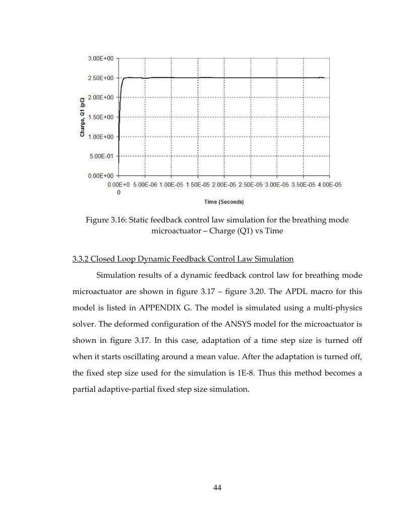
3.16 Static feedback control law simulation for the breathing mode microactuator – Charge (Q1) vs Time............................................................. 44
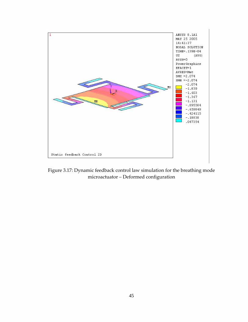
3.17 Dynamic feedback control law simulation for the breathing mode microactuator – Deformed configuration....................................................... 45
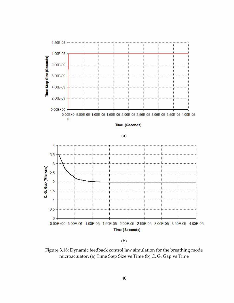
3.18 Dynamic feedback control law simulation for the breathing mode microactuator. (a) Time Step Size vs Time (b) C. G. Gap vs Time.............. 46
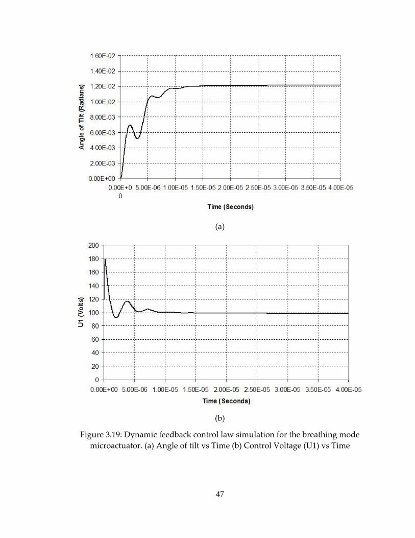
3.19 Dynamic feedback control law simulation for the breathing mode microactuator. (a) Angle of tilt vs Time (b) Control Voltage (U1) vs Time ..................................................................................................................... 47
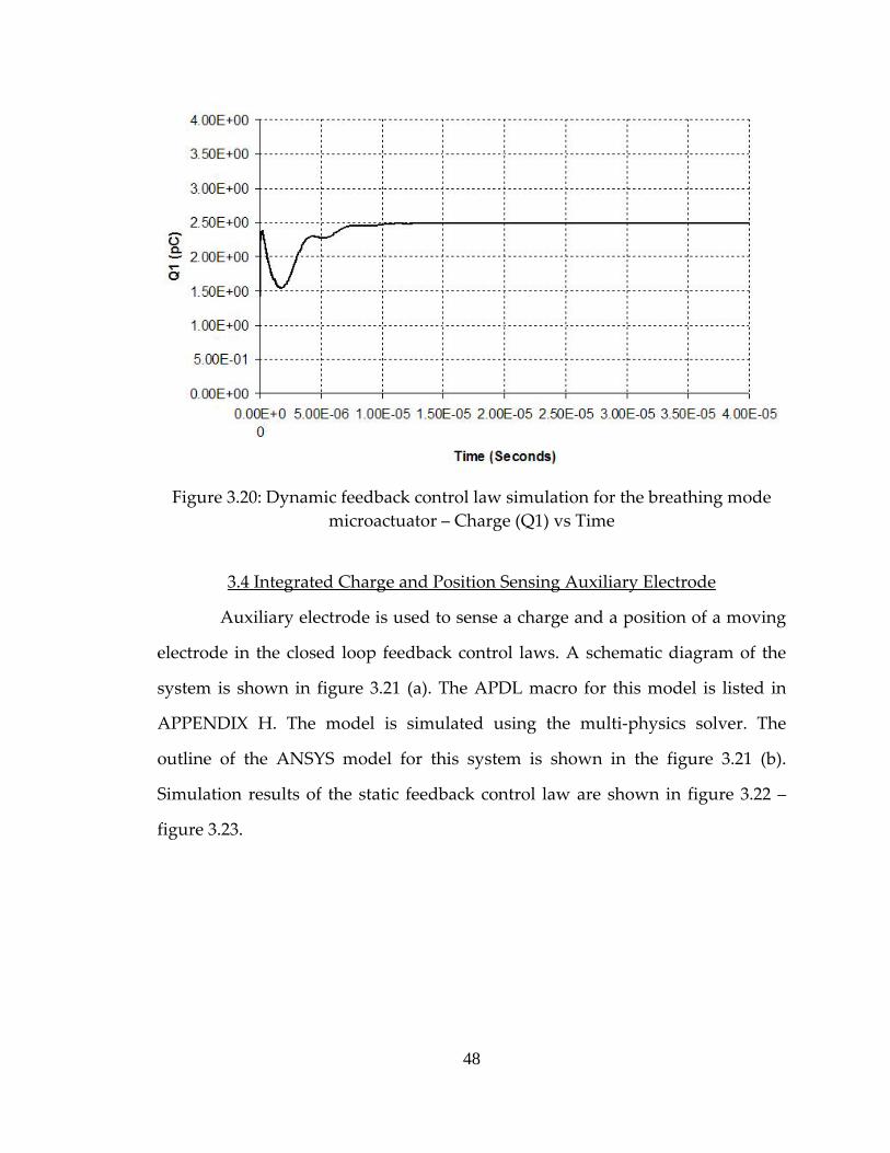
3.20 Dynamic feedback control law simulation for the breathing mode microactuator – Charge (Q1) vs Time............................................................. 48
3.21 Integrated charge and position sensor. (a) Schematic diagram of the sensor with a control circuit (b) Outline of the ANSYS model ................... 49
3.22 Static feedback control law simulation for the integrated charge and position sensor. (a) Gap vs Time (b) Control Voltage vs Time ................... 50
3.23 Static feedback control law simulation for the integrated charge and position sensor – Charge vs Time.................................................................... 51
3.24 Both ends fixed RF MEMS Switch (a) ANSYS model (b) Deformed configuration....................................................................................................... 52
3.25 Static feedback control law simulation for the both ends fixed RF MEMS Switch. (a) Time Step Size vs Time (b) Gap vs Time ....................... 53
3.26 Static feedback control law simulation for the both ends fixed RF MEMS Switch. (a) Control Voltage vs Time (b) Charge vs Time................ 54
3.27 The micromirror fabricated at the Maddox laboratory at TTU (a) SEM image ‐ undeformed state (b) NT1100 LCD image ‐ deformed state ...................................................................................................................... 56
3.28 Finite element analysis of the micromirror ‐ deformed configuration (a) at 25 volts (b) at 26 volts ..................................................... 57
3.29 Interferometric profile for the deformed micromirror (a) at 0 volts (b) at 17 volts....................................................................................................... 58
x
CHAPTER I
1. INTRODUCTION
Micro Electro Mechanical Systems (MEMS), Micro Opto Electro
Mechanical Systems (MOEMS) and Nano Electro Mechanical Systems (NEMS)
are evolving fields. These devices are comprised of miniature parts and operate
at micro and nano levels. The actuation technique for them may include
piezoelectric, electrostatic, thermal, shape memory alloys or magnetic actuation.
Among these devices, electrostatic devices are most widely used. What makes
them so popular? The answer is their simplicity, flexibility of operation and that
they can be fabricated using standard microelectronics fabrication processes and
materials. They are superior to traditional devices because of low power
requirements, low losses and low costs. Their actuation may be analog or digital.
Digital devices have only two possible configurations whereas analog devices
can operate in many configurations. Electrostatic actuators are widely used in the
following: micromirrors in optical switching, RF MEMS switches used in
Static and dynamic closed loop feedback control laws for the breathing
mode microactuator are given by following equations. Here equations (2.3) and
(2.4) are the static output feedback control laws for each of the two control
electrodes, where the quantities are the same as for the 1‐DOF device, for the
appropriate electrode as indicated by the subscripts. Equations (2.5) and (2.6) are
the dynamic output feedback control laws, analogous to (2.2). Here v is the
velocity of the movable electrode center of mass, and υ is the angular velocity
about the c.m.
( )1 1 1 1du V K Q Q= − − (2.3)
( )2 2 2 2du V K Q Q= − − (2.4)
13
( ) ( )1 11 1 1 1 1
1
24d x
Q Qu V R l v K Q QAε
⎛ ⎞+= − Ω − − −⎜ ⎟
⎝ ⎠ (2.5)
( ) ( )2 22 2 2 2 2
2
24d x
Q Qu V R l v K Q QAε
⎛ ⎞+= − Ω − − −⎜ ⎟
⎝ ⎠ (2.6)
2.4 Procedure
2.4.1 Integration of Circuit and Electrostatic Analyses
This section details the solution procedure at each time step, including
evaluation of the control law. Multiple drive electrodes are assumed, each
associated with a circuit that, for the present study, is assumed to consist of a
voltage source ui and a series resistance, ri. The current in the ith drive circuit is Ii.
Given a source voltage ui, the drive electrode voltage Vdi depends on Ii. Because
of element type incompatibilities, the Vdi and Ii cannot be found within the
ANSYS solver, and are instead computed between time steps in an APDL macro.
This is done by solving state equations for the Vdi. The following general
procedure is implemented at each time step.
At the start of the nth time step, the movable electrode configuration q(n)
and velocity v(n) are known from the previous time step, as are the charges Qi(n)
and voltages Vdi(n) on the drive electrodes (all these quantities must be initialized
for the first time step) and the lumped capacitances, Cij(n) = Cij(q(n)). Based on these
values the control voltages ui(n), which may depend on any or all of these, are
computed. The state equations for the Vdi include the lumped capacitances Cij, the
Vdi, and the ui. These equations are used to obtain Vdi(n+1). The Vdi(n+1) are applied as
boundary conditions in an ANSYS analysis, which returns as output q(n+1), v(n+1),
14
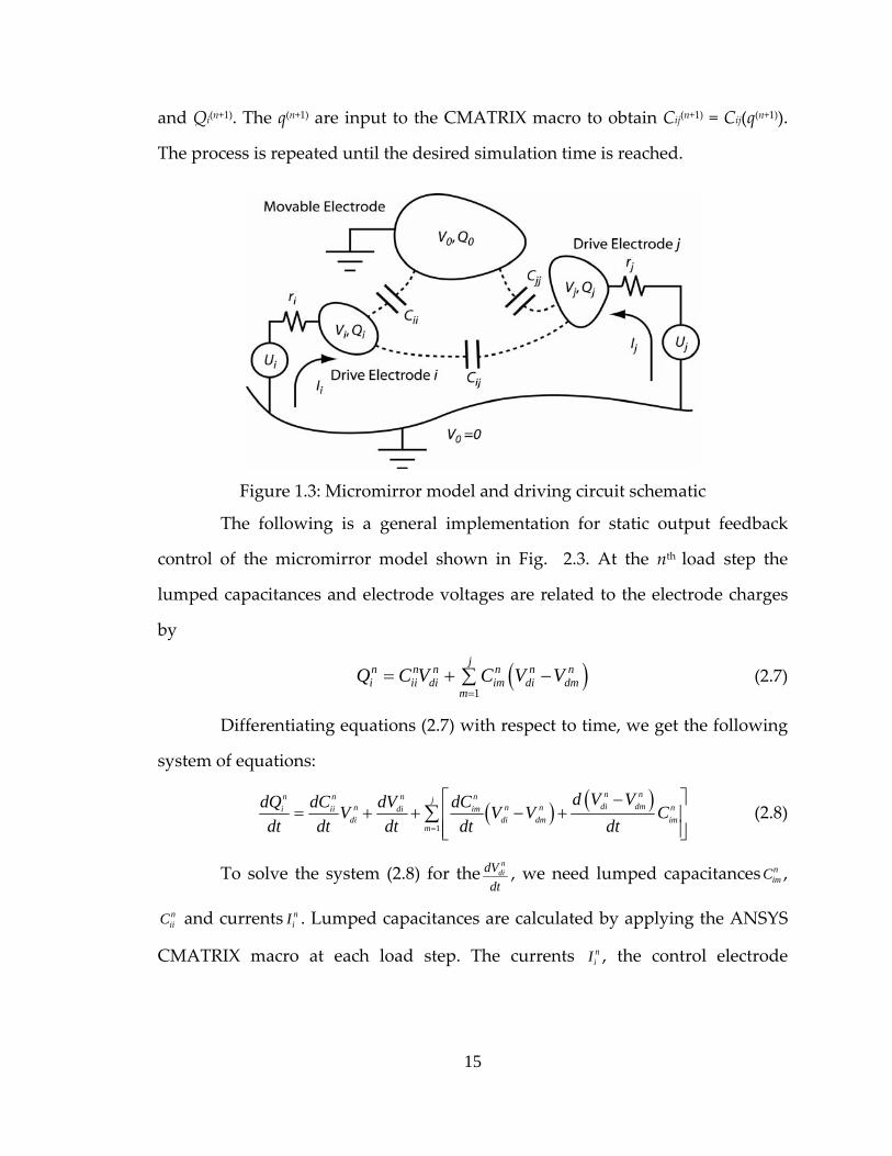
and Qi(n+1). The q(n+1) are input to the CMATRIX macro to obtain Cij(n+1) = Cij(q(n+1)).
The process is repeated until the desired simulation time is reached.
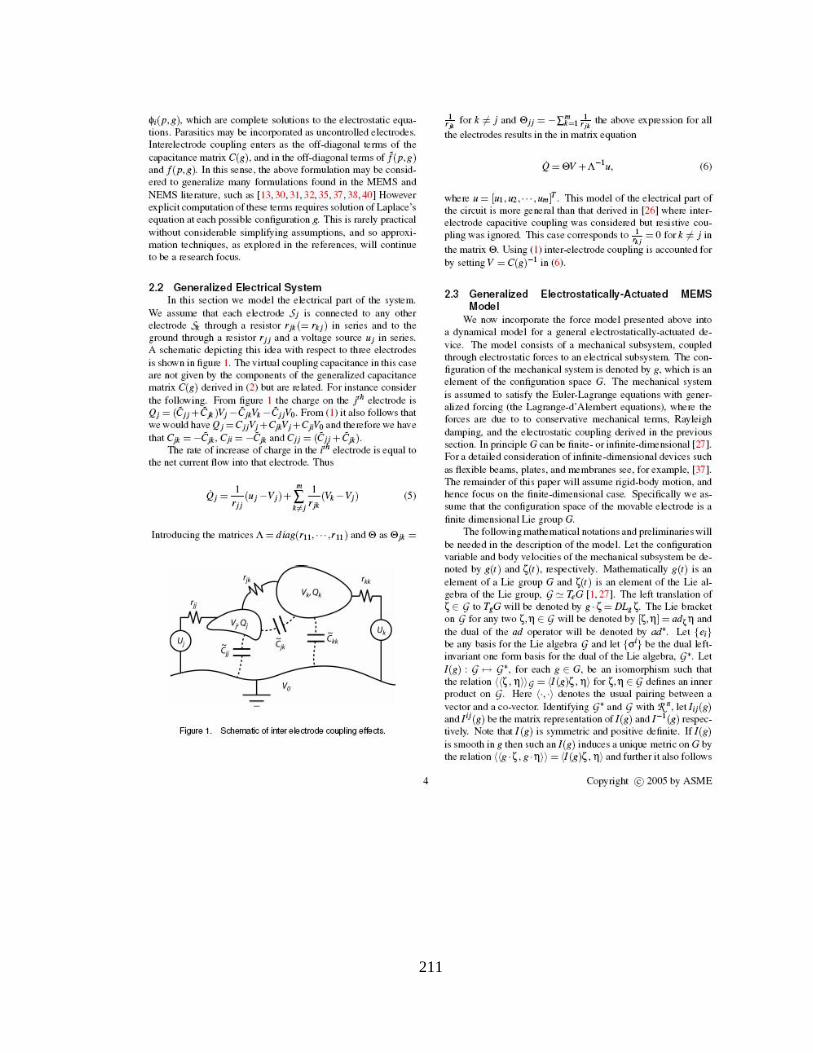
Figure 1.3: Micromirror model and driving circuit schematic
The following is a general implementation for static output feedback
control of the micromirror model shown in Fig. 2.3. At the nth load step the
lumped capacitances and electrode voltages are related to the electrode charges
by
(2.7) ( )1
jn n n n n ni ii di im di dm
mQ C V C V V
== + −∑
Differentiating equations (2.7) with respect to time, we get the following
system of equations:
( ) ( )1
n nn n n njdi dmn n ni ii di im
di di dm imm
d V VdQ dC dV dCV V Vdt dt dt dt dt=
nC⎡ ⎤−
= + + − +⎢ ⎥⎢ ⎥⎣ ⎦
∑ (2.8)
To solve the system (2.8) for then
didVdt
, we need lumped capacitances ,
and currents . Lumped capacitances are calculated by applying the ANSYS
CMATRIX macro at each load step. The currents , the control electrode
nimC
niiC n
iI
niI
15
voltages Vdj(n+1) and the drive voltages uj(n+1) for the (n+1)th load step are calculated
by (2.9), (2.10), and (2.11):
n n
n i i di
i
dQ u VIdt R
−= =
ni (2.9)
1n
n n didi di n
dVV Vdt
+ t= + Δ (2.10)
( )1n n ni di iu V K Q Q+ = − − i (2.11)
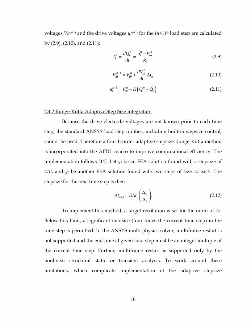
2.4.2 Runge‐Kutta Adaptive Step Size Integration
Because the drive electrode voltages are not known prior to each time
step, the standard ANSYS load step utilities, including built‐in stepsize control,
cannot be used. Therefore a fourth‐order adaptive stepsize Runge‐Kutta method
is incorporated into the APDL macro to improve computational efficiency. The
implementation follows [14]. Let y1 be an FEA solution found with a stepsize of
2∆t, and y2 be another FEA solution found with two steps of size ∆t each. The
stepsize for the next time step is then
01
1n nt S t+
⎛ ⎞ΔΔ = Δ ⎜ ⎟Δ⎝ ⎠
. (2.12)
To implement this method, a target resolution is set for the norm of ∆1.
Below this limit, a significant increase (four times the current time step) in the
time step is permitted. In the ANSYS multi‐physics solver, multiframe restart is
not supported and the end time at given load step must be an integer multiple of
the current time step. Further, multiframe restart is supported only by the
nonlinear structural static or transient analysis. To work around these
limitations, which complicate implementation of the adaptive stepsize
16
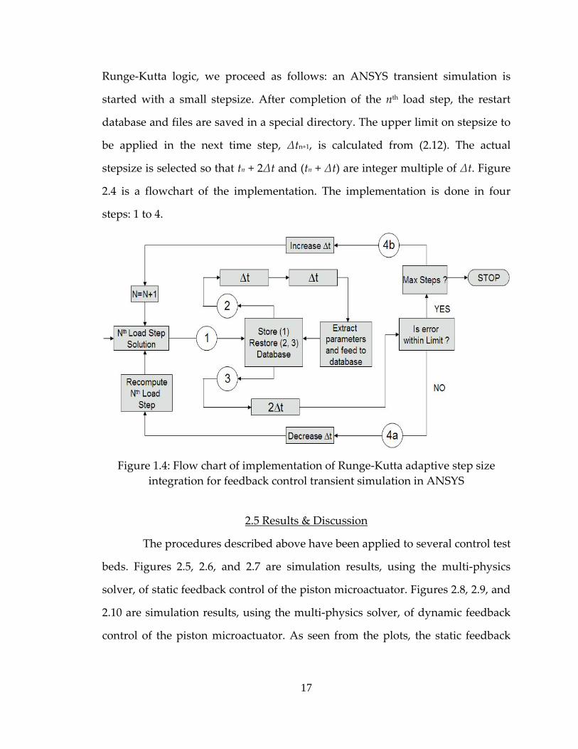
Runge‐Kutta logic, we proceed as follows: an ANSYS transient simulation is
started with a small stepsize. After completion of the nth load step, the restart
database and files are saved in a special directory. The upper limit on stepsize to
be applied in the next time step, ∆tn+1, is calculated from (2.12). The actual
stepsize is selected so that tn + 2∆t and (tn + ∆t) are integer multiple of ∆t. Figure
2.4 is a flowchart of the implementation. The implementation is done in four
steps: 1 to 4.
Figure 1.4: Flow chart of implementation of Runge‐Kutta adaptive step size
integration for feedback control transient simulation in ANSYS
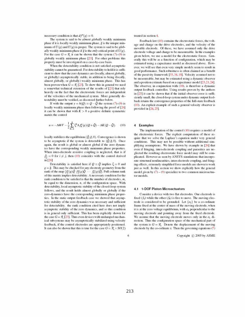
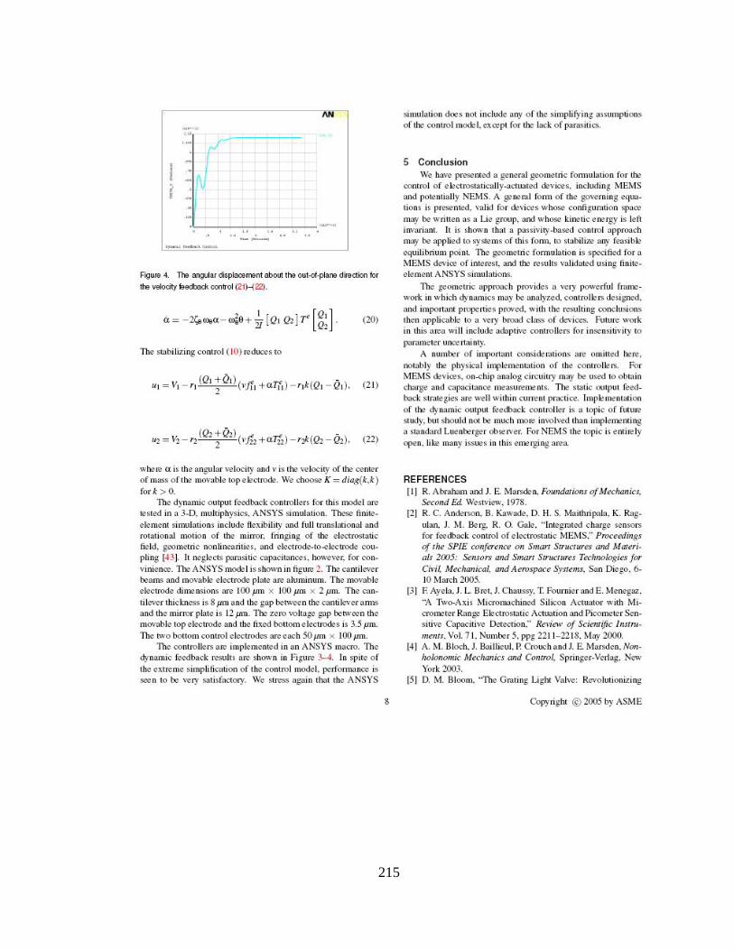
2.5 Results & Discussion
The procedures described above have been applied to several control test
beds. Figures 2.5, 2.6, and 2.7 are simulation results, using the multi‐physics
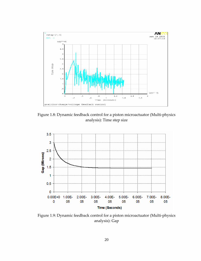
solver, of static feedback control of the piston microactuator. Figures 2.8, 2.9, and
2.10 are simulation results, using the multi‐physics solver, of dynamic feedback
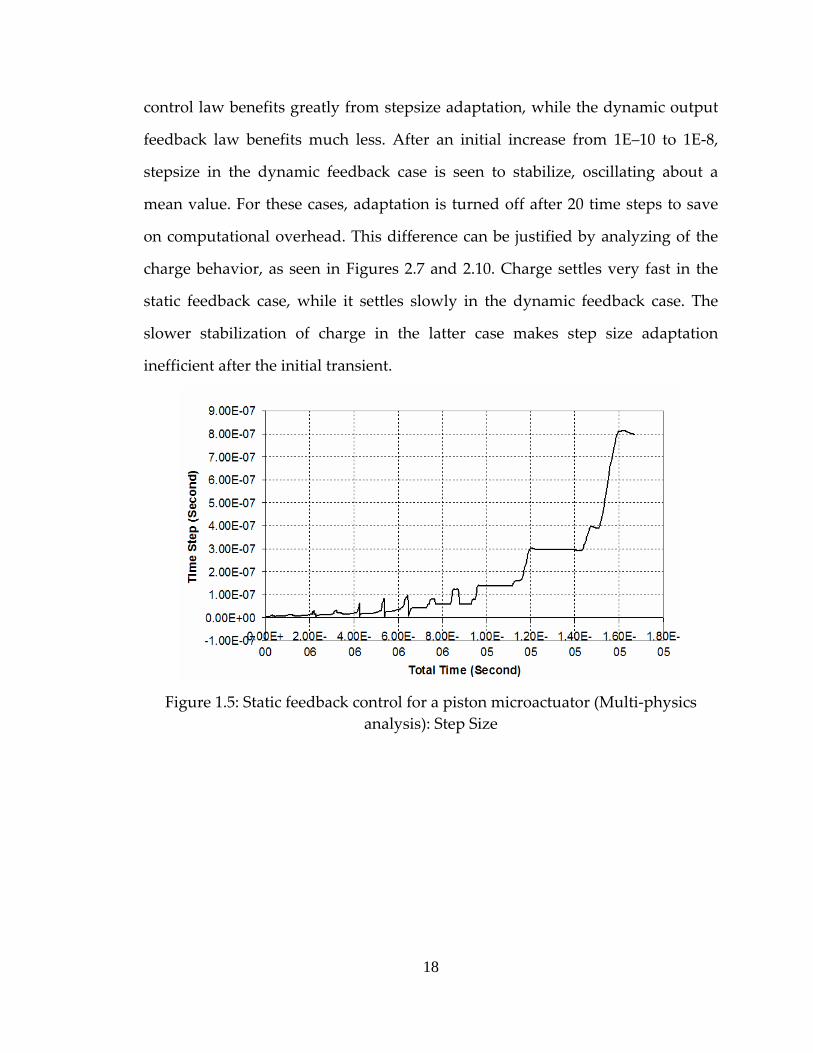
control of the piston microactuator. As seen from the plots, the static feedback
17
control law benefits greatly from stepsize adaptation, while the dynamic output
feedback law benefits much less. After an initial increase from 1E–10 to 1E‐8,
stepsize in the dynamic feedback case is seen to stabilize, oscillating about a
mean value. For these cases, adaptation is turned off after 20 time steps to save
on computational overhead. This difference can be justified by analyzing of the
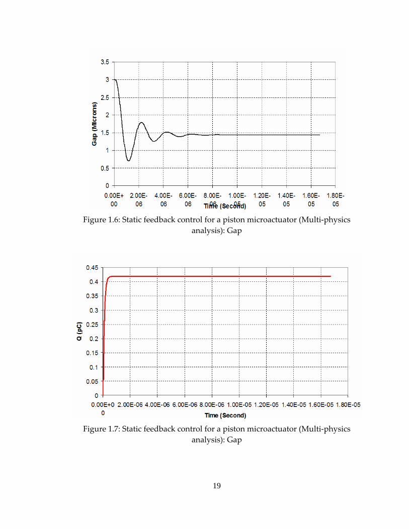
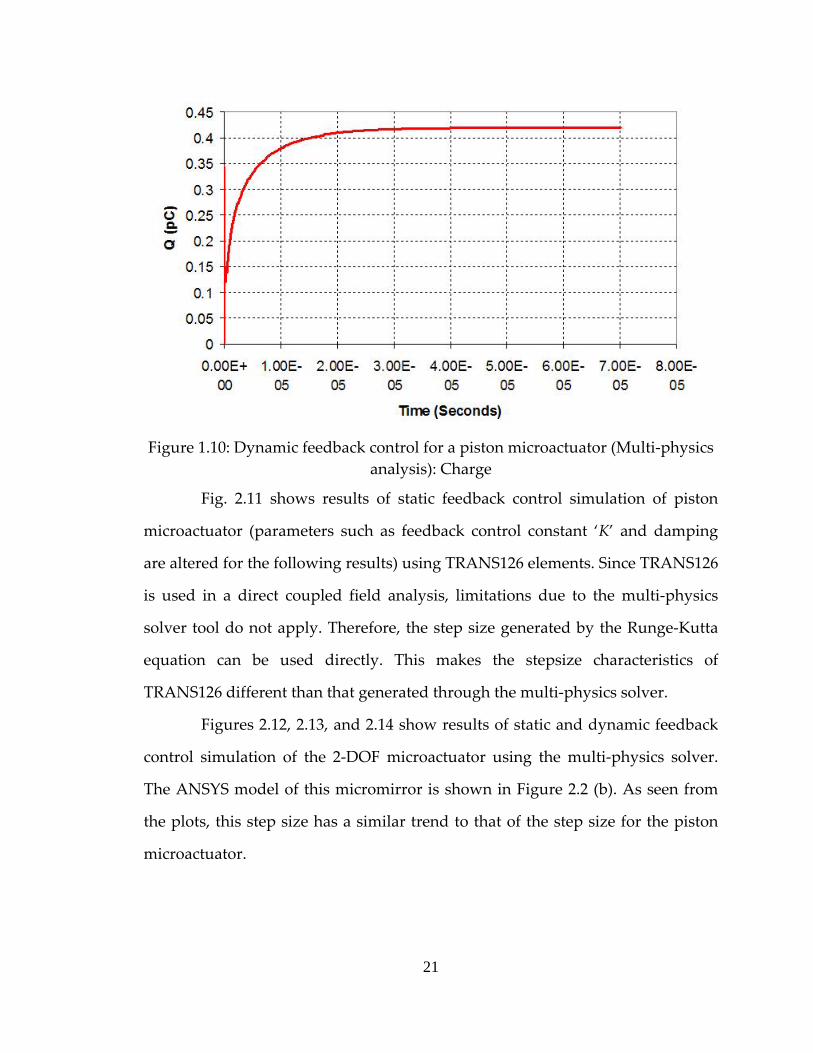
charge behavior, as seen in Figures 2.7 and 2.10. Charge settles very fast in the
static feedback case, while it settles slowly in the dynamic feedback case. The
slower stabilization of charge in the latter case makes step size adaptation
inefficient after the initial transient.
Figure 1.5: Static feedback control for a piston microactuator (Multi‐physics
analysis): Step Size
18
Figure 1.6: Static feedback control for a piston microactuator (Multi‐physics
analysis): Gap
Figure 1.7: Static feedback control for a piston microactuator (Multi‐physics
analysis): Gap
19
Figure 1.8: Dynamic feedback control for a piston microactuator (Multi‐physics
analysis): Time step size
Figure 1.9: Dynamic feedback control for a piston microactuator (Multi‐physics
analysis): Gap
20
Figure 1.10: Dynamic feedback control for a piston microactuator (Multi‐physics
analysis): Charge
Fig. 2.11 shows results of static feedback control simulation of piston
microactuator (parameters such as feedback control constant ‘K’ and damping
are altered for the following results) using TRANS126 elements. Since TRANS126
is used in a direct coupled field analysis, limitations due to the multi‐physics
solver tool do not apply. Therefore, the step size generated by the Runge‐Kutta
equation can be used directly. This makes the stepsize characteristics of
TRANS126 different than that generated through the multi‐physics solver.
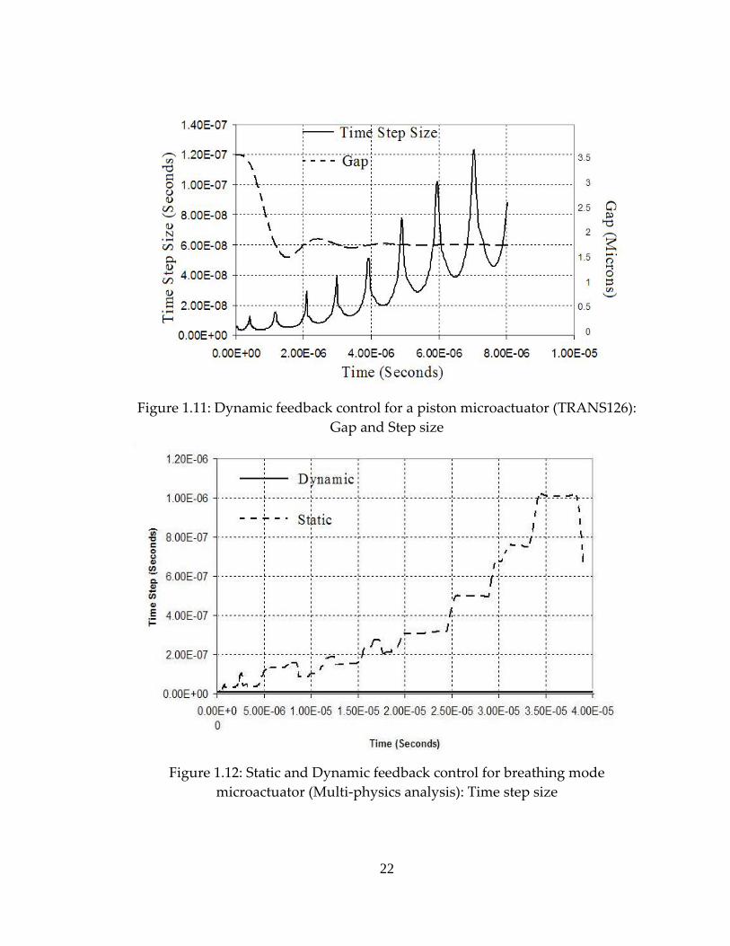
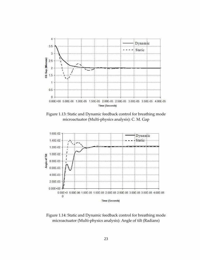
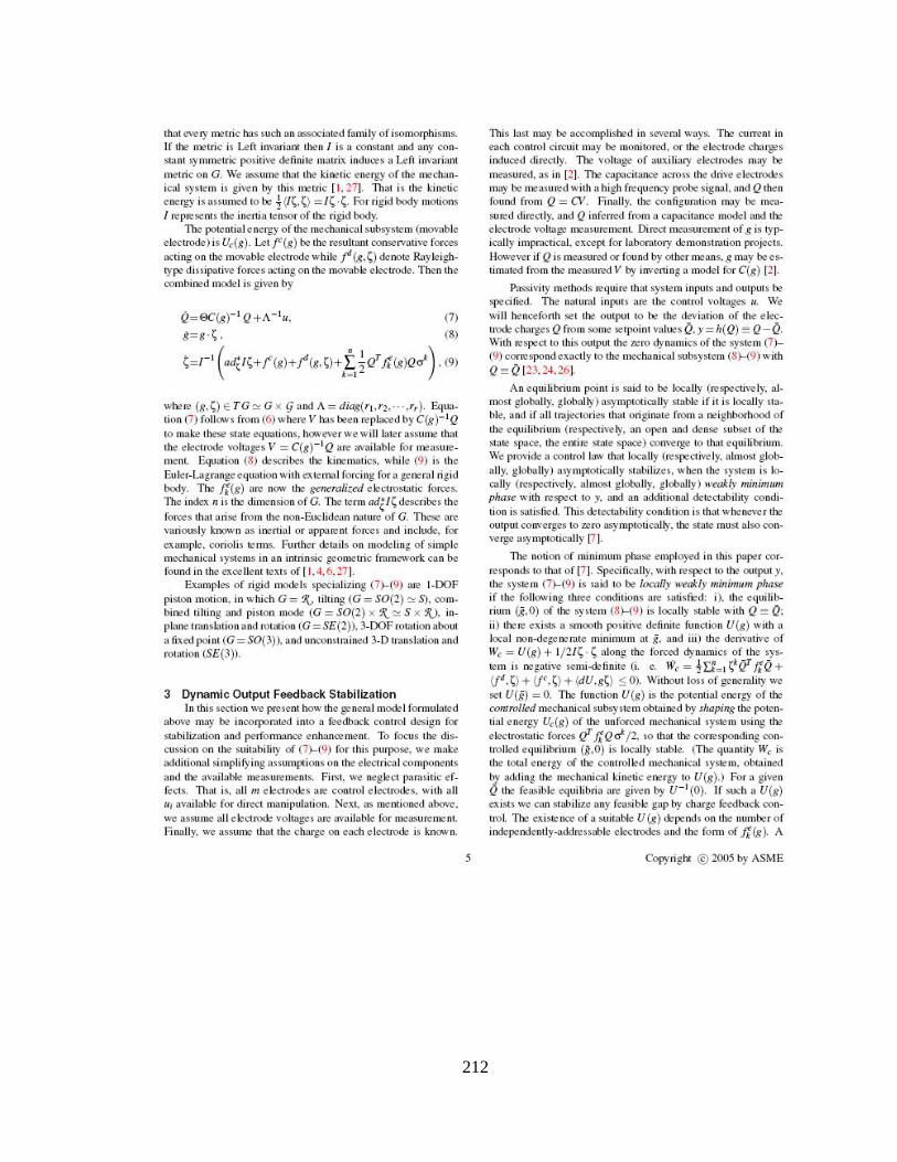
Figures 2.12, 2.13, and 2.14 show results of static and dynamic feedback
control simulation of the 2‐DOF microactuator using the multi‐physics solver.
The ANSYS model of this micromirror is shown in Figure 2.2 (b). As seen from
the plots, this step size has a similar trend to that of the step size for the piston
microactuator.
21
Figure 1.11: Dynamic feedback control for a piston microactuator (TRANS126):
Gap and Step size
Figure 1.12: Static and Dynamic feedback control for breathing mode
microactuator (Multi‐physics analysis): Time step size
22
Figure 1.13: Static and Dynamic feedback control for breathing mode
microactuator (Multi‐physics analysis): C. M. Gap
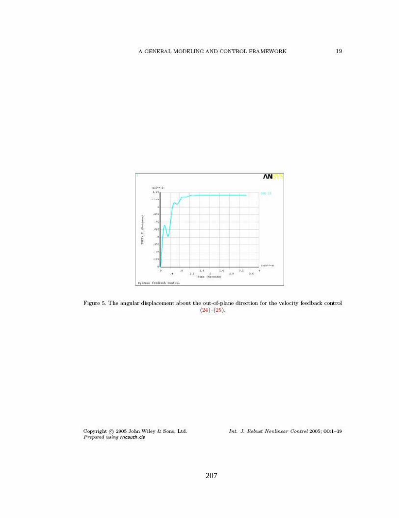
Figure 1.14: Static and Dynamic feedback control for breathing mode microactuator (Multi‐physics analysis): Angle of tilt (Radians)
23
2.6 Conclusion
ANSYS simulation of electrostatic MEMS for validation of control laws
presents challenges due to element type incompatibilities and stepsize
management. We have embedded the FEA simulation within an APDL macro
that updates the drive circuit states and implements adaptive stepsize control.
This simulation facility has been successfully applied to a number of device
simulations. Further, Runge‐Kutta adaptive step size integration method is
observed to be very efficient for transient simulation of static feedback control
systems. This methodology has improved computational efficiency of systems
involving feedback dependent boundary conditions.
24
2.7 References
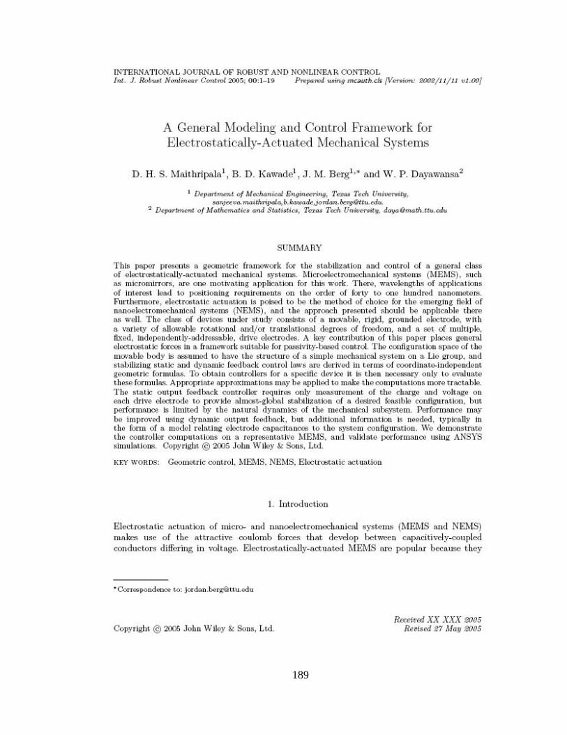
[1] D. H. S. Maithripala, B. D. Kawade, J. M. Berg, W. P. Dayawansa, “A
General Modelling and Control Framework for electrostatically actuated mechanical Systems”, International Journal of Robust and Nonlinear Control, To Appear.
[2] Robert C. Anderson, Balasaheb Kawade, Kandiah Ragulan, D. H. S.
Maithripala, Jordan M. Berg, Richard O. Gale, W. P. Dayawansa, “Integrated Charge and Position Sensing for Feedback Control of Electrostatic MEMS”, SPIE Conference on Smart Structures and Materials 2005: Sensors and Smart Structures Technologies for Civil, Mechanical, and Aerospace Systems, San Diego, CA, March, 2005.
[3] D. H. S. Maithripala, Jordan M Berg, W. P. Dayawansa, “Control of an
Electrostatic MEMS using Static and Dynamic Output Feedback”, ASME Journal of Dynamical Systems Measurement and Control, to appear, September 2005.
[4] D. H. S. Maithripala, Jordan M. Berg, W. P. Dayawansa, “Capacitive
Stabilization of an Electrostatic Actuator: An Output Feedback Viewpoint”, Proceedings of the 2003 American Control Conference, Denver, CO, June 4–6, 2003, pp. 4053–4058.
[5] Sanjeeva Maithripala, Jordan M Berg, and W. P. Dayawansa, “Nonlinear
Dynamic Output Feedback Stabilization of Electrostatically Actuated MEMS”, Proceedings of the CDC, Maui, HW, 2003.
[6] Joseph I. Seegar, and Bernhard E. Boser, “Dynamics and Control of
Parallel Plate Actuators Beyond the Electrostatic Instability”, Proceedings of the Tenth International Conference on Solid‐State Sensors and Actuators (Transducers ’99), Sendai, Japan, 7–9 June 1999; 474–477.
25
[7] Joseph I. Seegar, and Bernhard E. Boser, “Charge Control of Parallel‐Plate, Electrostatic Actuators and the Tip‐In Instability”, Journal of Microelectromechanical Systems 2003; 12(5):656–671.
[8] Jinghong Chen, Wendellin Weingartner, Alexi‐Azarov, and Randy C.
Giles, “Tilt Angle Stabilization of Electrostatically Actuated Micromechanical Mirrors Beyond the Pull‐In point”, Journal of Microelectromechanical Systems 2003; 13(6) :988‐997.
[9] Elmer S. Hung, and Stephan D. Senturia, “Generating Efficient Dynamic
Models for Microelectromechanical Systems from a Few Finite‐Element Simulation Runs”, IEEE Journal of Microelectromechanical Systems 1999; 8(3):280‐289.
[10] Mohammad I. Younis, Eihab M. Abdel‐Rahman, and Ali Nayfeh, “A
Reduced‐Order Model for Electrically Actuated Microbeam‐Based MEMS”, Journal of Microelectromechanical Systems 2003; 12(5) :672‐680.
[11] Gang Li, and N. R. Aluru, “Efficient Mixed‐Domain Analysis of
Electrostatic MEMS”, IEEE Transactions on Computer‐Aided design of integrated circuits and systems, 22(9):1228‐1242.
[12] Ofir Bochobza‐degani, David Elata, and Yael Nemirovsky, “An Efficient
DIPIE Algorithm for CAD of Electrostatically Actuated MEMS Devices”, Journal of Microelectromechanical Systems 2003; 12(5):612‐620.
[13] ANSYS Release 10.0 Documentation, ANSYS Inc, Canonsburg, PA, 2005. [14] William H. Press, Bian P. Flannery, Saul A. Teukolsky, and William T.
Vetterling, “Numerical Recipies”, 1986. [15] Yu Sun, D. Piyabongkarn, A. Sezen, B. J. Nelson, R. Rajamani, “ A high‐
aspect‐ratio tow‐axis electrostatic miroactuator with extended travel range”, Sensors and Actuators A, 2002, 102(1, 2):49‐60.
26
[16] Yael Nemirovsky, Ofir Bochobza‐Degani, “A Methodology and Model for the Pull‐In Parameters of Electrostatic Actuators”, Journal of Microelectromechanical Systems 2001; 10(4):601‐615.
[17] Edward L. Chan, Robert W. Dutton, “Electrostatic Micromechanical
Actuators with Extended Range of Travel”, Journal of Microelectromechanical Systems 2000; 9(3):321‐328.
27
CHAPTER III
3. RESULTS AND DISCUSSION
As discussed in chapter I, electrostatic microactuators have several
applications in various fields. RF MEMS Switch, piston micromirror, torsion
micromirror, and breathing mode microactuators are widely used
electromechanical actuators. In this chapter, simulation results of closed loop
static and dynamic feedback control laws for various microactuators are
presented.
3.1 Parallel Plate Capacitor
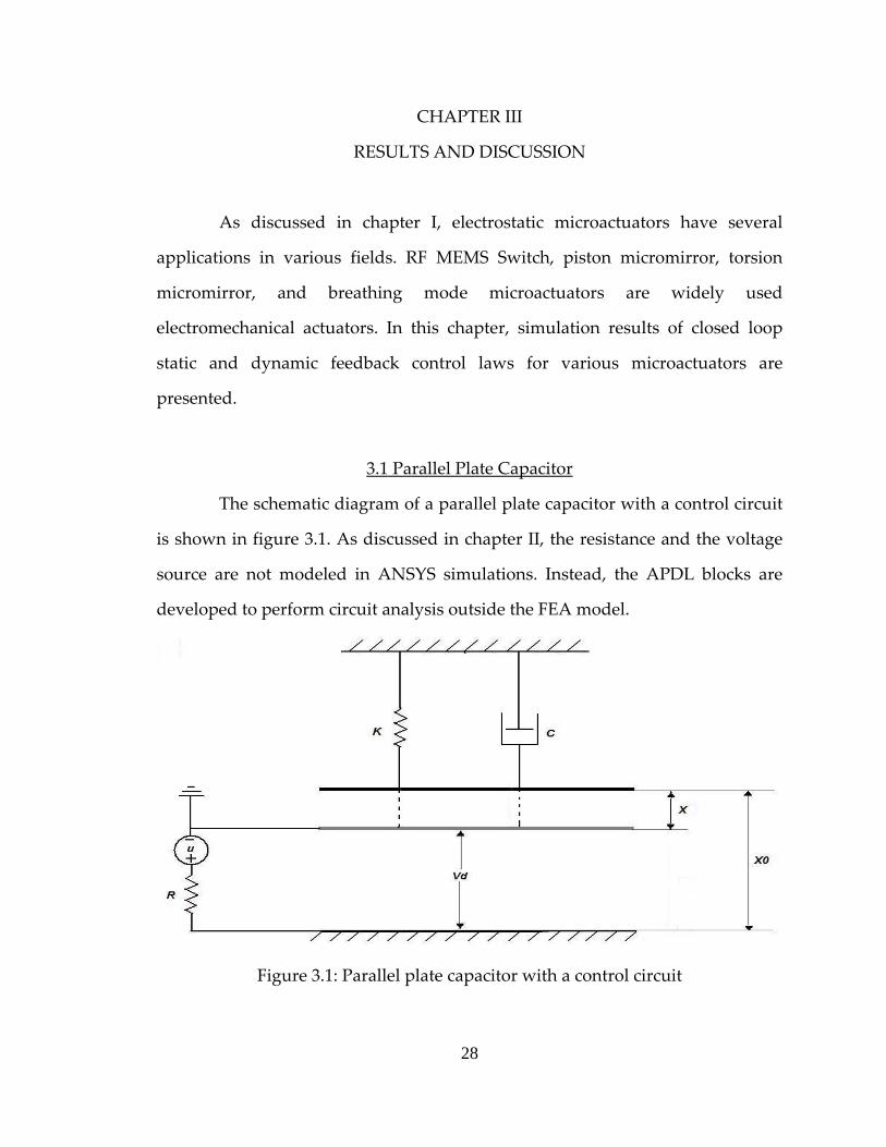
The schematic diagram of a parallel plate capacitor with a control circuit
is shown in figure 3.1. As discussed in chapter II, the resistance and the voltage
source are not modeled in ANSYS simulations. Instead, the APDL blocks are
developed to perform circuit analysis outside the FEA model.
Figure 3.1: Parallel plate capacitor with a control circuit
28
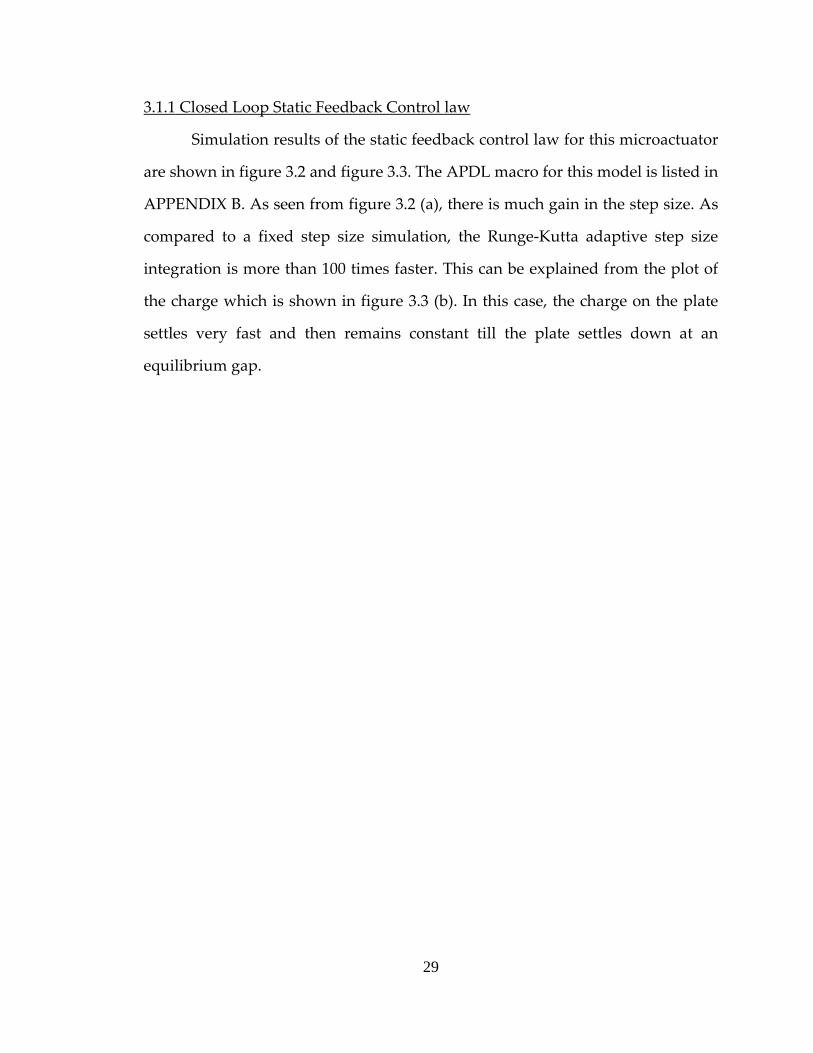
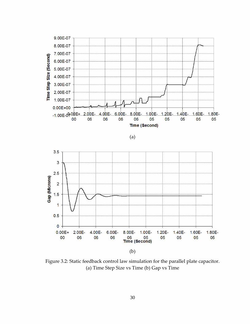
3.1.1 Closed Loop Static Feedback Control law
Simulation results of the static feedback control law for this microactuator
are shown in figure 3.2 and figure 3.3. The APDL macro for this model is listed in
APPENDIX B. As seen from figure 3.2 (a), there is much gain in the step size. As
compared to a fixed step size simulation, the Runge‐Kutta adaptive step size
integration is more than 100 times faster. This can be explained from the plot of
the charge which is shown in figure 3.3 (b). In this case, the charge on the plate
settles very fast and then remains constant till the plate settles down at an
equilibrium gap.
29
(a)
(b)
Figure 3.2: Static feedback control law simulation for the parallel plate capacitor. (a) Time Step Size vs Time (b) Gap vs Time
30
(a)
(b)
Figure 3.3: Static feedback control law simulation for the parallel plate capacitor. (a) Control Voltage vs Time (b) Charge vs Time
31
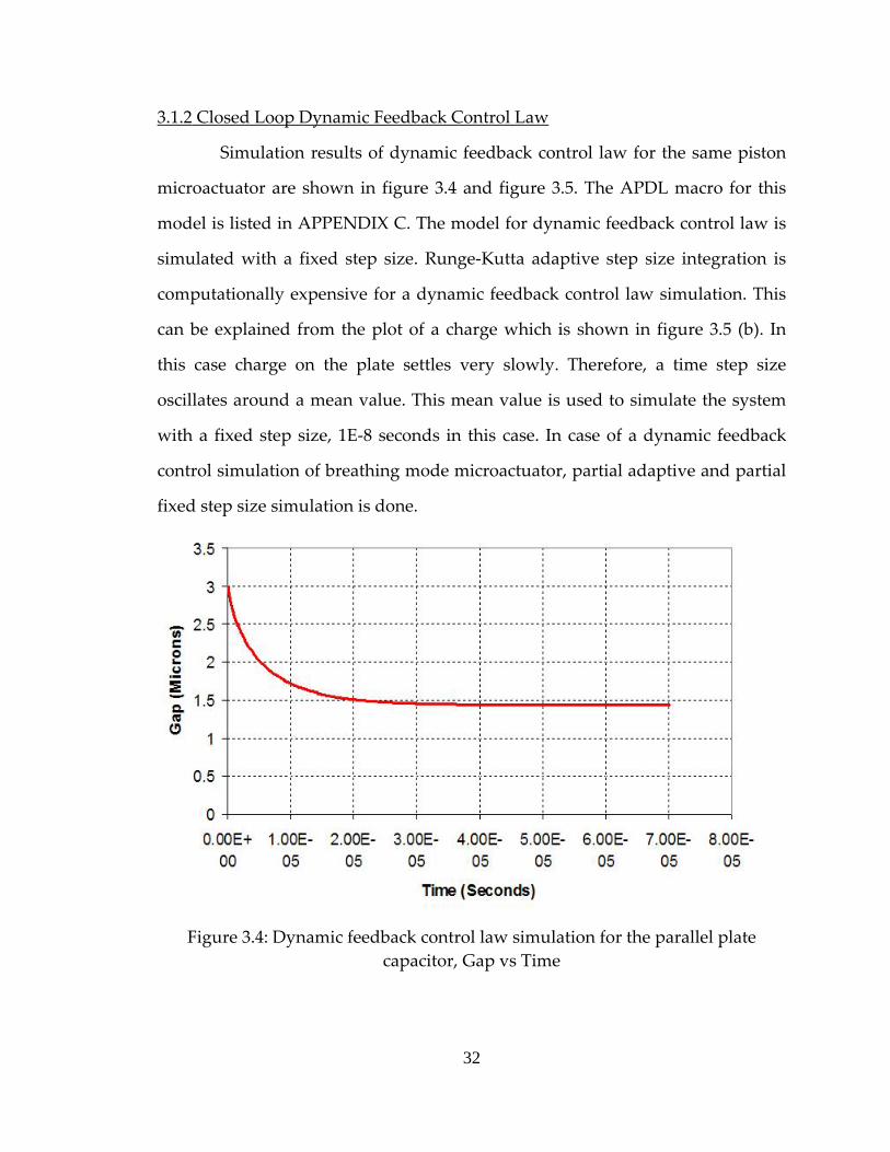
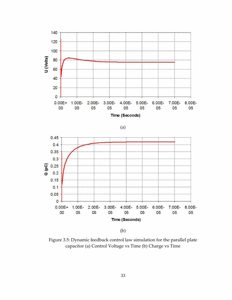
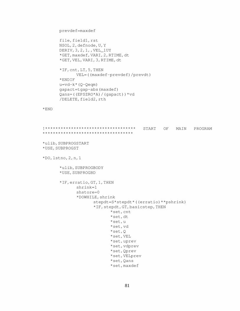
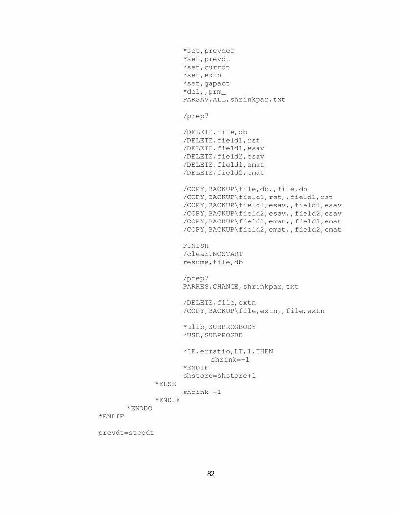
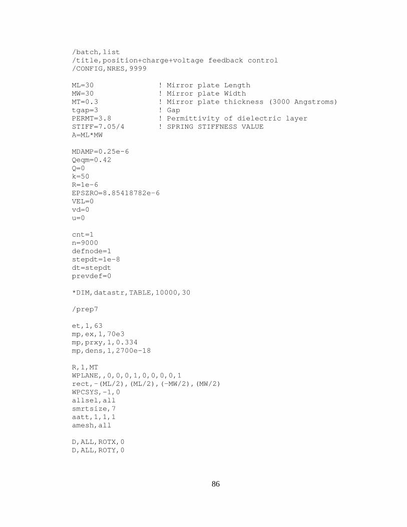
3.1.2 Closed Loop Dynamic Feedback Control Law
Simulation results of dynamic feedback control law for the same piston
microactuator are shown in figure 3.4 and figure 3.5. The APDL macro for this
model is listed in APPENDIX C. The model for dynamic feedback control law is
simulated with a fixed step size. Runge‐Kutta adaptive step size integration is
computationally expensive for a dynamic feedback control law simulation. This
can be explained from the plot of a charge which is shown in figure 3.5 (b). In
this case charge on the plate settles very slowly. Therefore, a time step size
oscillates around a mean value. This mean value is used to simulate the system
with a fixed step size, 1E‐8 seconds in this case. In case of a dynamic feedback
control simulation of breathing mode microactuator, partial adaptive and partial
fixed step size simulation is done.
Figure 3.4: Dynamic feedback control law simulation for the parallel plate capacitor, Gap vs Time
32
(a)
(b)
Figure 3.5: Dynamic feedback control law simulation for the parallel plate capacitor (a) Control Voltage vs Time (b) Charge vs Time
33
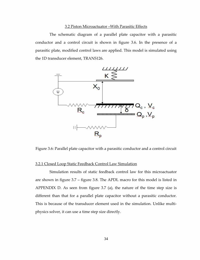
3.2 Piston Microactuator –With Parasitic Effects
The schematic diagram of a parallel plate capacitor with a parasitic
conductor and a control circuit is shown in figure 3.6. In the presence of a
parasitic plate, modified control laws are applied. This model is simulated using
the 1D transducer element, TRANS126.
Figure 3.6: Parallel plate capacitor with a parasitic conductor and a control circuit
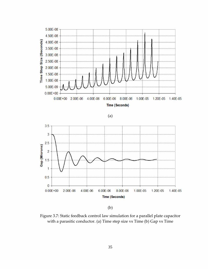
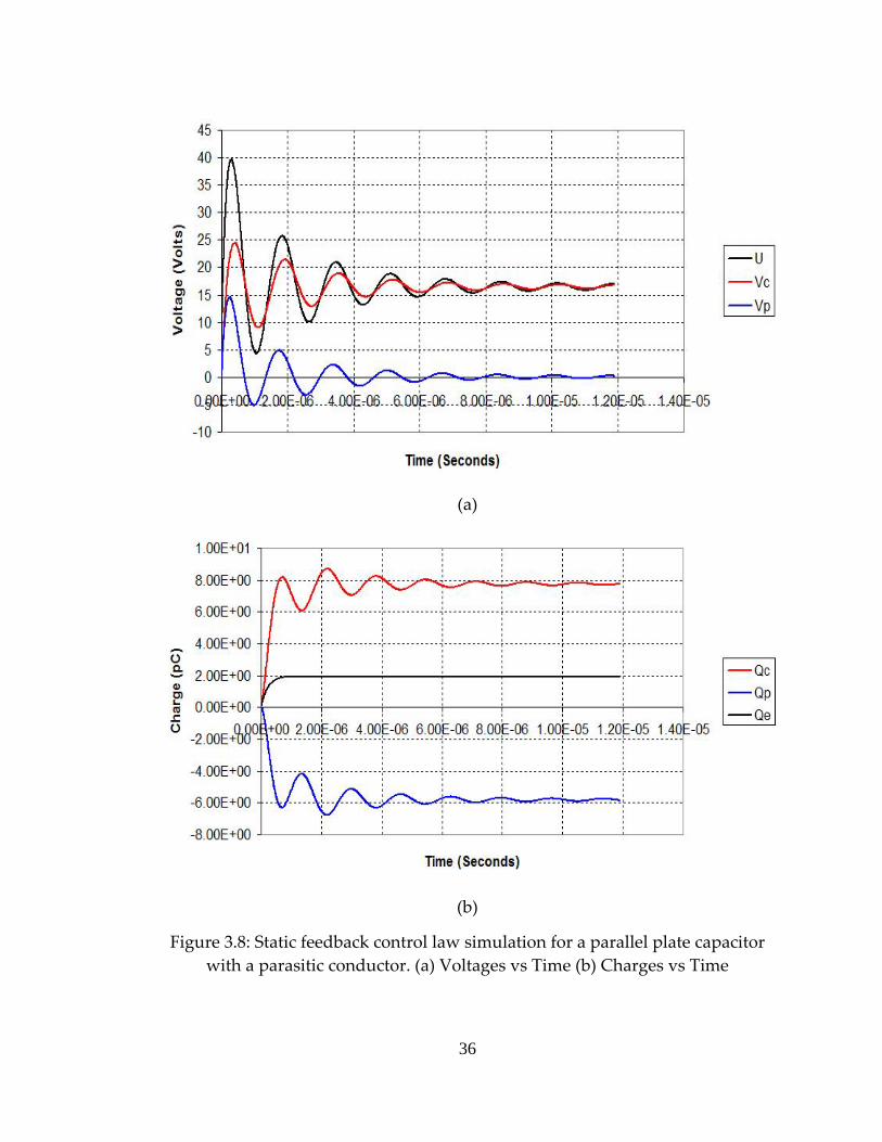
3.2.1 Closed Loop Static Feedback Control Law Simulation
Simulation results of static feedback control law for this microactuator
are shown in figure 3.7 – figure 3.8. The APDL macro for this model is listed in
APPENDIX D. As seen from figure 3.7 (a), the nature of the time step size is
different than that for a parallel plate capacitor without a parasitic conductor.
This is because of the transducer element used in the simulation. Unlike multi‐
physics solver, it can use a time step size directly.
34
(a)
(b)
Figure 3.7: Static feedback control law simulation for a parallel plate capacitor with a parasitic conductor. (a) Time step size vs Time (b) Gap vs Time
35
(a)
(b)
Figure 3.8: Static feedback control law simulation for a parallel plate capacitor with a parasitic conductor. (a) Voltages vs Time (b) Charges vs Time
36
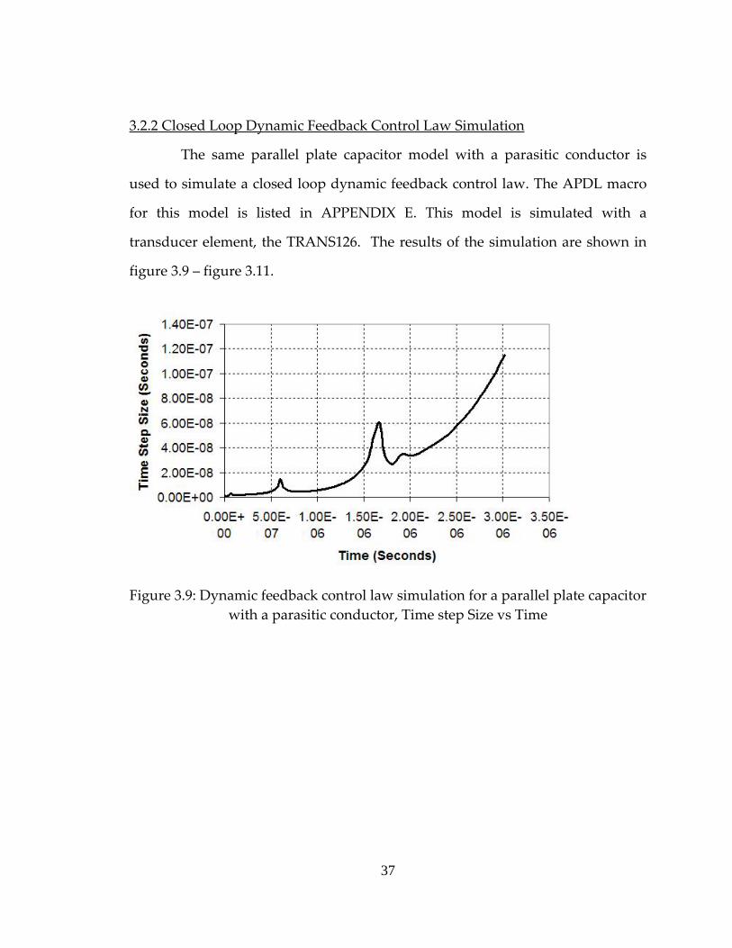
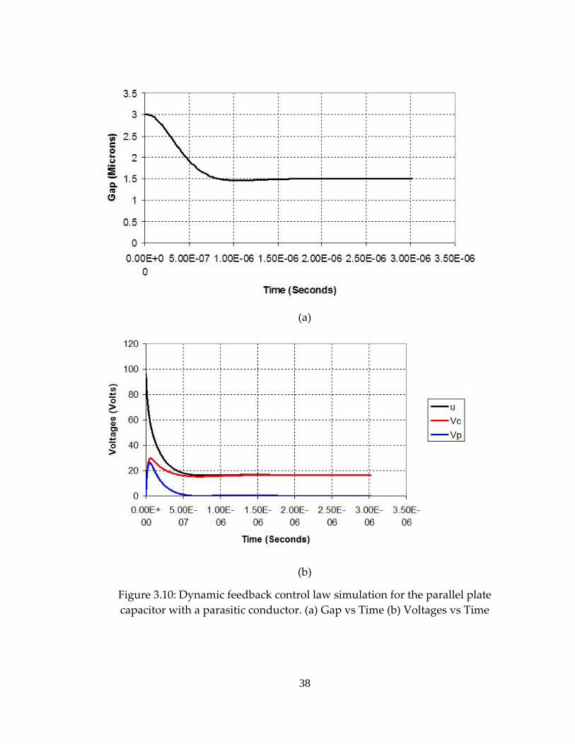
3.2.2 Closed Loop Dynamic Feedback Control Law Simulation
The same parallel plate capacitor model with a parasitic conductor is
used to simulate a closed loop dynamic feedback control law. The APDL macro
for this model is listed in APPENDIX E. This model is simulated with a
transducer element, the TRANS126. The results of the simulation are shown in
figure 3.9 – figure 3.11.
Figure 3.9: Dynamic feedback control law simulation for a parallel plate capacitor with a parasitic conductor, Time step Size vs Time
37
(a)
(b)
Figure 3.10: Dynamic feedback control law simulation for the parallel plate capacitor with a parasitic conductor. (a) Gap vs Time (b) Voltages vs Time
38
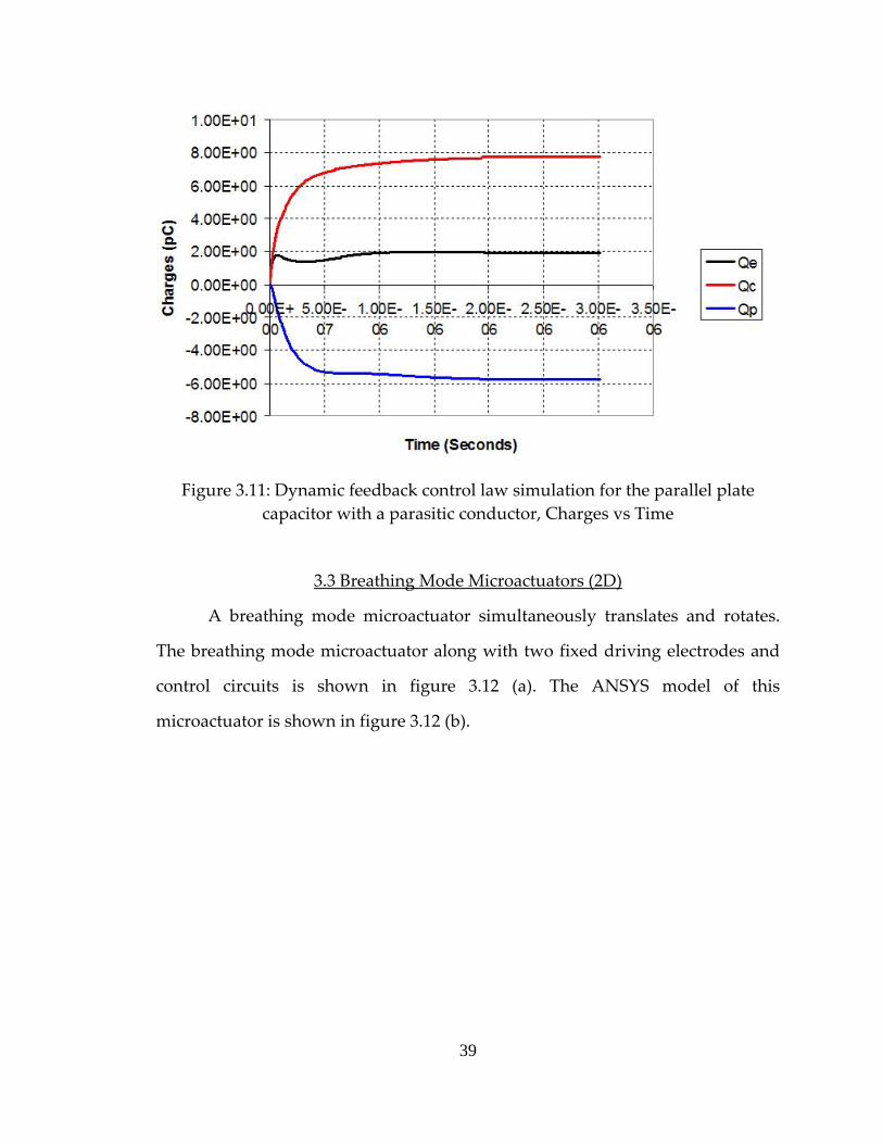
Figure 3.11: Dynamic feedback control law simulation for the parallel plate capacitor with a parasitic conductor, Charges vs Time
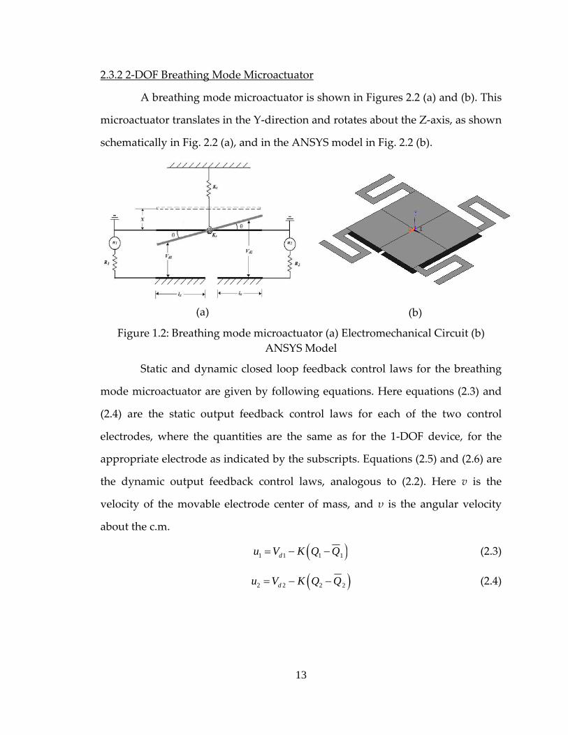
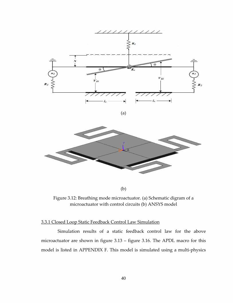
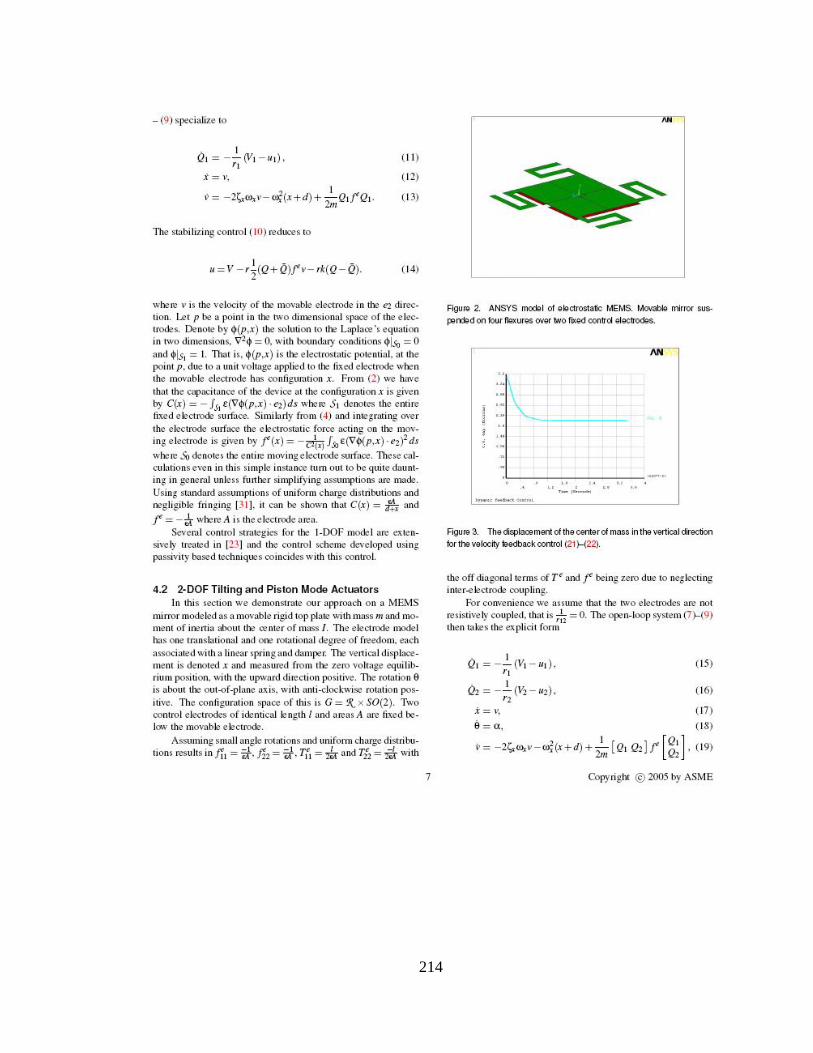
3.3 Breathing Mode Microactuators (2D)
A breathing mode microactuator simultaneously translates and rotates.
The breathing mode microactuator along with two fixed driving electrodes and
control circuits is shown in figure 3.12 (a). The ANSYS model of this
microactuator is shown in figure 3.12 (b).
39
(a)
(b)
Figure 3.12: Breathing mode microactuator. (a) Schematic digram of a microactuator with control circuits (b) ANSYS model
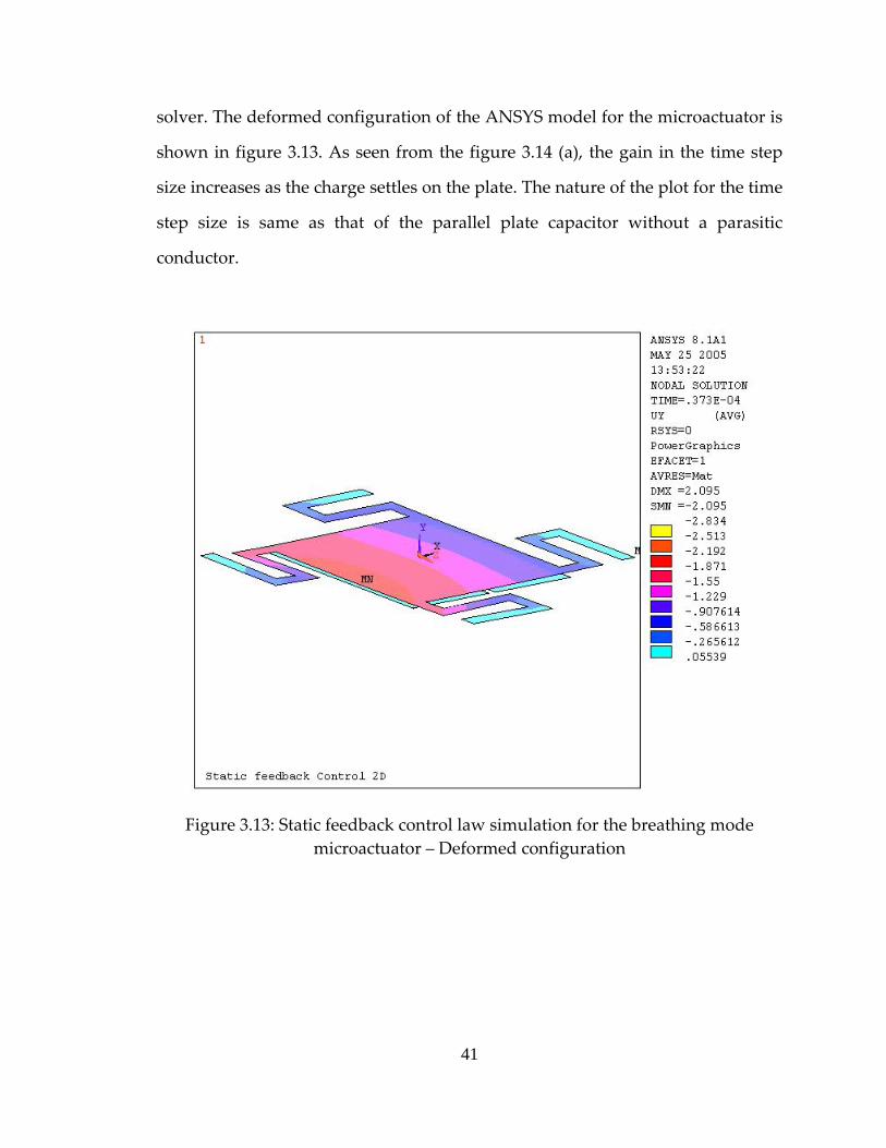
3.3.1 Closed Loop Static Feedback Control Law Simulation
Simulation results of a static feedback control law for the above
microactuator are shown in figure 3.13 – figure 3.16. The APDL macro for this
model is listed in APPENDIX F. This model is simulated using a multi‐physics
40
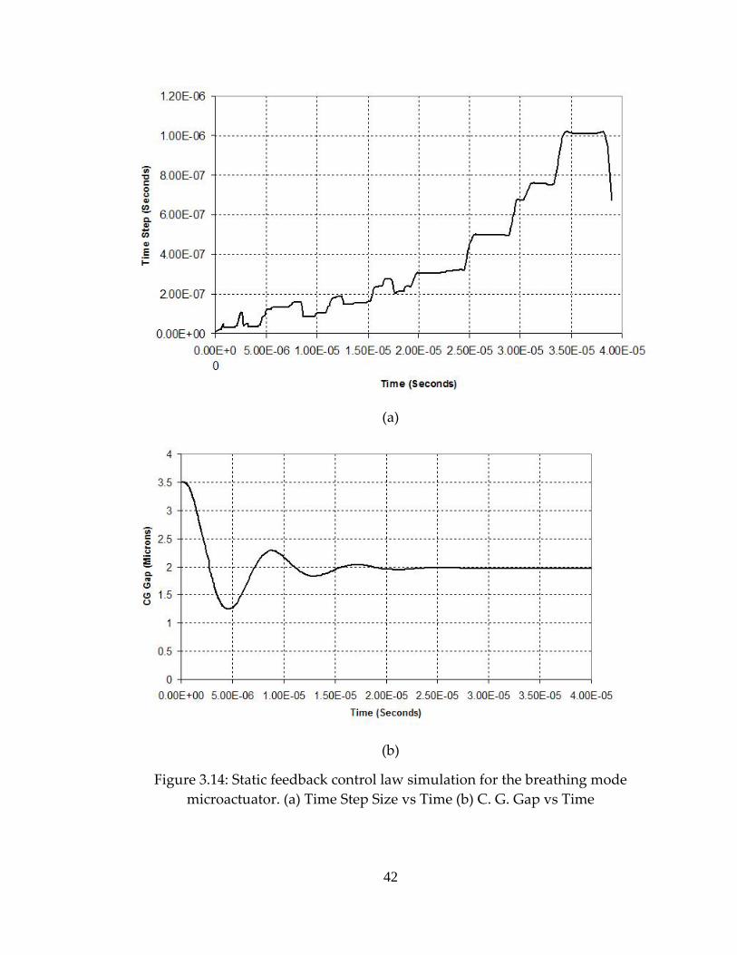
solver. The deformed configuration of the ANSYS model for the microactuator is
shown in figure 3.13. As seen from the figure 3.14 (a), the gain in the time step
size increases as the charge settles on the plate. The nature of the plot for the time
step size is same as that of the parallel plate capacitor without a parasitic
conductor.
Figure 3.13: Static feedback control law simulation for the breathing mode microactuator – Deformed configuration
41
(a)
(b)
Figure 3.14: Static feedback control law simulation for the breathing mode microactuator. (a) Time Step Size vs Time (b) C. G. Gap vs Time
42
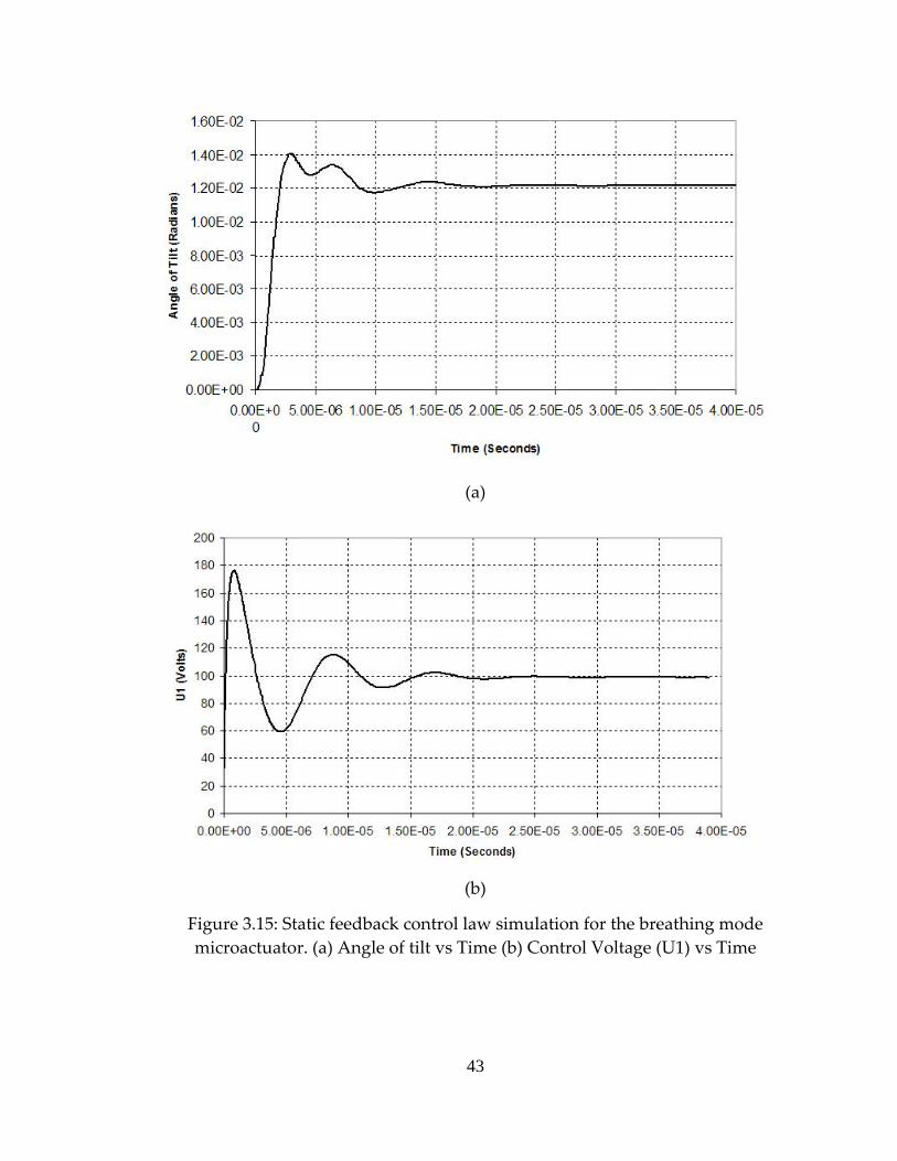
(a)
(b)
Figure 3.15: Static feedback control law simulation for the breathing mode microactuator. (a) Angle of tilt vs Time (b) Control Voltage (U1) vs Time
43
Figure 3.16: Static feedback control law simulation for the breathing mode microactuator – Charge (Q1) vs Time
3.3.2 Closed Loop Dynamic Feedback Control Law Simulation
Simulation results of a dynamic feedback control law for breathing mode
microactuator are shown in figure 3.17 – figure 3.20. The APDL macro for this
model is listed in APPENDIX G. The model is simulated using a multi‐physics
solver. The deformed configuration of the ANSYS model for the microactuator is
shown in figure 3.17. In this case, adaptation of a time step size is turned off
when it starts oscillating around a mean value. After the adaptation is turned off,
the fixed step size used for the simulation is 1E‐8. Thus this method becomes a
Figure 3.17: Dynamic feedback control law simulation for the breathing mode microactuator – Deformed configuration
45
(a)
(b)
Figure 3.18: Dynamic feedback control law simulation for the breathing mode microactuator. (a) Time Step Size vs Time (b) C. G. Gap vs Time
46
(a)
(b)
Figure 3.19: Dynamic feedback control law simulation for the breathing mode microactuator. (a) Angle of tilt vs Time (b) Control Voltage (U1) vs Time
47
Figure 3.20: Dynamic feedback control law simulation for the breathing mode microactuator – Charge (Q1) vs Time
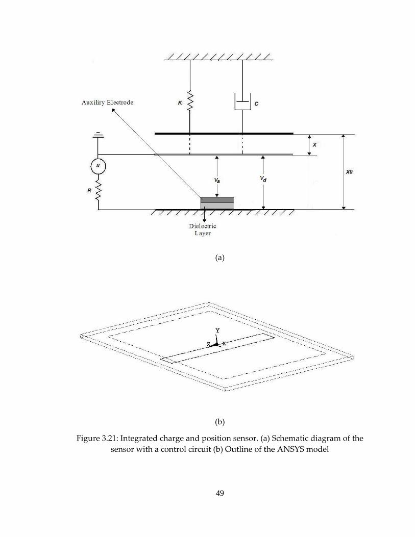
3.4 Integrated Charge and Position Sensing Auxiliary Electrode
Auxiliary electrode is used to sense a charge and a position of a moving
electrode in the closed loop feedback control laws. A schematic diagram of the
system is shown in figure 3.21 (a). The APDL macro for this model is listed in
APPENDIX H. The model is simulated using the multi‐physics solver. The
outline of the ANSYS model for this system is shown in the figure 3.21 (b).
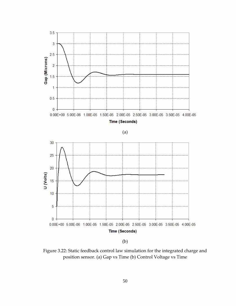
Simulation results of the static feedback control law are shown in figure 3.22 –
figure 3.23.
48
(a)
(b)
Figure 3.21: Integrated charge and position sensor. (a) Schematic diagram of the sensor with a control circuit (b) Outline of the ANSYS model
49
(a)
(b)
Figure 3.22: Static feedback control law simulation for the integrated charge and position sensor. (a) Gap vs Time (b) Control Voltage vs Time
50
(a)
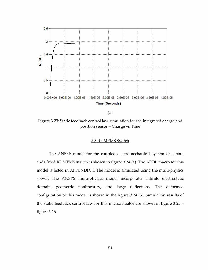
Figure 3.23: Static feedback control law simulation for the integrated charge and position sensor – Charge vs Time
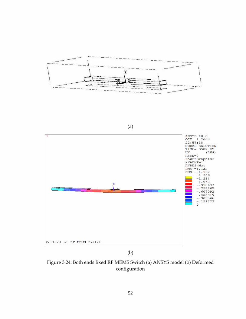
3.5 RF MEMS Switch
The ANSYS model for the coupled electromechanical system of a both
ends fixed RF MEMS switch is shown in figure 3.24 (a). The APDL macro for this
model is listed in APPENDIX I. The model is simulated using the multi‐physics
solver. The ANSYS multi‐physics model incorporates infinite electrostatic
domain, geometric nonlinearity, and large deflections. The deformed
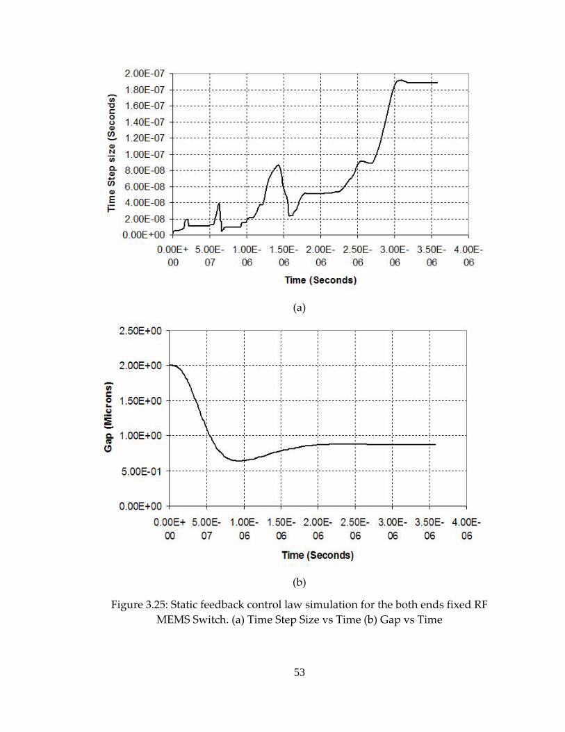
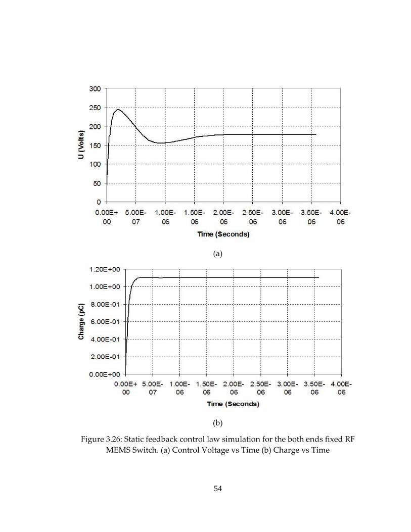
configuration of this model is shown in the figure 3.24 (b). Simulation results of
the static feedback control law for this microactuator are shown in figure 3.25 –
figure 3.26.
51
(a)
(b)
Figure 3.24: Both ends fixed RF MEMS Switch (a) ANSYS model (b) Deformed configuration
52
(a)
(b)
Figure 3.25: Static feedback control law simulation for the both ends fixed RF MEMS Switch. (a) Time Step Size vs Time (b) Gap vs Time
53
(a)
(b)
Figure 3.26: Static feedback control law simulation for the both ends fixed RF MEMS Switch. (a) Control Voltage vs Time (b) Charge vs Time
54
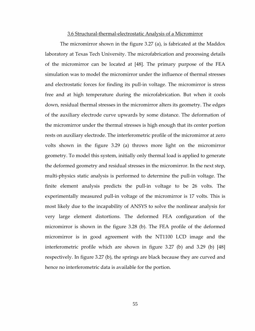
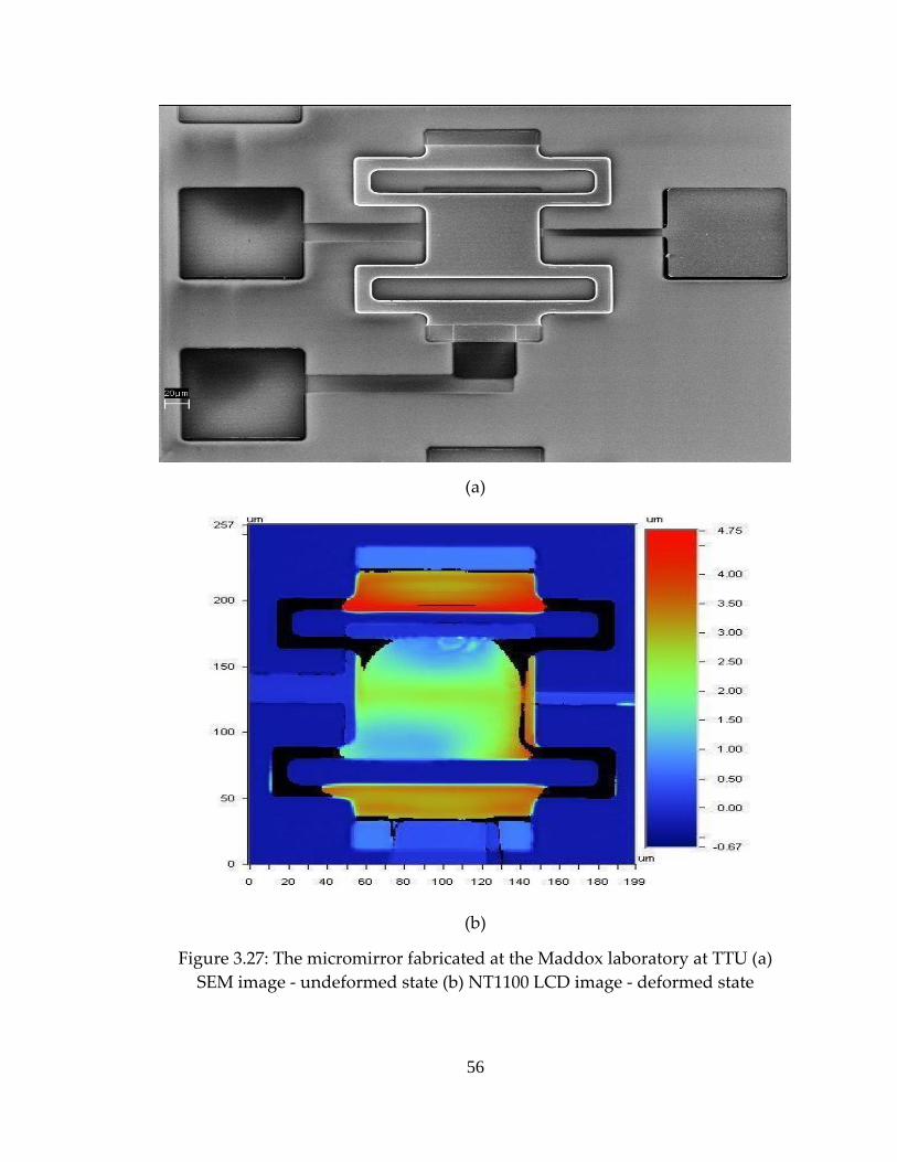
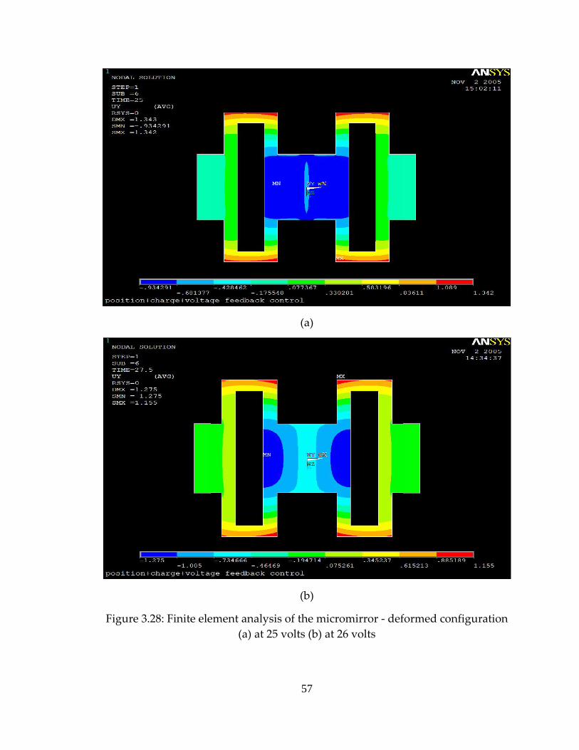
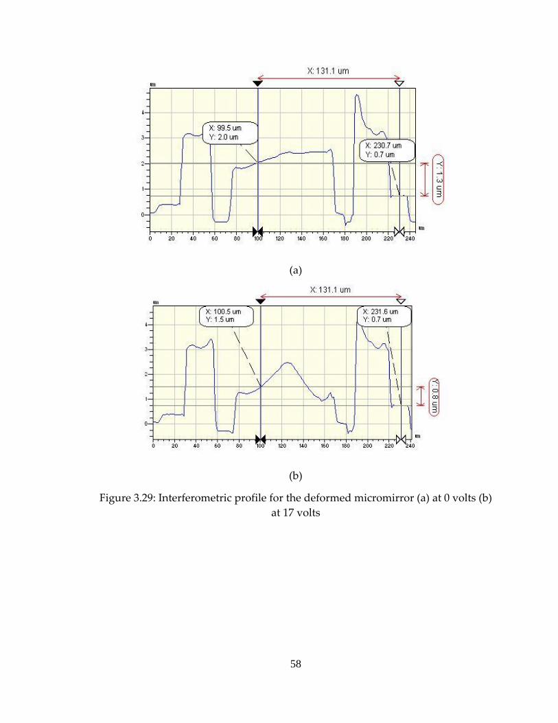
3.6 Structural‐thermal‐electrostatic Analysis of a Micromirror
The micromirror shown in the figure 3.27 (a), is fabricated at the Maddox
laboratory at Texas Tech University. The microfabrication and processing details
of the micromirror can be located at [48]. The primary purpose of the FEA
simulation was to model the micromirror under the influence of thermal stresses
and electrostatic forces for finding its pull‐in voltage. The micromirror is stress
free and at high temperature during the microfabrication. But when it cools
down, residual thermal stresses in the micromirror alters its geometry. The edges
of the auxiliary electrode curve upwards by some distance. The deformation of
the micromirror under the thermal stresses is high enough that its center portion
rests on auxiliary electrode. The interferometric profile of the micromirror at zero
volts shown in the figure 3.29 (a) throws more light on the micromirror
geometry. To model this system, initially only thermal load is applied to generate
the deformed geometry and residual stresses in the micromirror. In the next step,
multi‐physics static analysis is performed to determine the pull‐in voltage. The
finite element analysis predicts the pull‐in voltage to be 26 volts. The
experimentally measured pull‐in voltage of the micromirror is 17 volts. This is
most likely due to the incapability of ANSYS to solve the nonlinear analysis for
very large element distortions. The deformed FEA configuration of the
micromirror is shown in the figure 3.28 (b). The FEA profile of the deformed
micromirror is in good agreement with the NT1100 LCD image and the
interferometric profile which are shown in figure 3.27 (b) and 3.29 (b) [48]
respectively. In figure 3.27 (b), the springs are black because they are curved and
hence no interferometric data is available for the portion.
55
(a)
(b)
Figure 3.27: The micromirror fabricated at the Maddox laboratory at TTU (a) SEM image ‐ undeformed state (b) NT1100 LCD image ‐ deformed state
56
(a)
(b)
Figure 3.28: Finite element analysis of the micromirror ‐ deformed configuration (a) at 25 volts (b) at 26 volts
57
(a)
(b)
Figure 3.29: Interferometric profile for the deformed micromirror (a) at 0 volts (b) at 17 volts
58
CHAPTER IV
4.CONCLUSIONS
Computational efficiency is an important factor in finite element
simulation. Nonlinear transient analysis of a coupled electromechanical system
can be computationally inefficient due to very strict convergence criteria and
iterative procedure of the solution. These limitations along with ANSYS
limitations worsen the simulation efficiency of feedback dependent control
systems. A generalized finite element test bed proposed in this project overcomes
two ANSYS limitations: An electrostatic and circuit analysis incompatibility and
a lack of multiframe restart capability for the multi‐physics solver.
The generalized FEA test bed can be implemented for all types of
coupled electromechanical systems with various structural DOF, a new model or
the same model with different parameters. The electrostatic and circuit analyses
are successfully combined in a single analysis without using circuit elements. As
discussed in the chapter II and III, the Runge‐Kutta adaptive step size integration
is very efficient in the case of static feedback control simulations. However, it is
still demanding for dynamic feedback control simulations. The efficiency of the
dynamic feedback control simulations can be increased by incorporating partial
adaptive and partial fixed step size simulation technique. In this technique, the
adaptation of a step size is turned off when the step size exhibits oscillatory
nature. Various representative coupled electromechanical devices are tested
using this generalized test bed. These simulations justify the efficiency of the
advanced simulation technique extending the basic functionality of the ANSYS
multi‐physics package.
59
CHAPTER V
5.FUTURE WORK
The objective of this project was to develop efficient simulation
techniques for the coupled electromechanical systems. Accuracy of the finite
element analysis is dependent on the mesh density and element shape distortion
at low gaps. In coupled electromechanical systems, as the microactuator moves
towards the driving electrode, the gap between them decreases. Electrostatic
elements in the gap undergo large deformation which is a basic cause of their
distortion. In a large deflection ANSYS analysis, element distortion may become
a serious limitation. The situation can be handled by remeshing the deformed
electrostatic domain at each load step. But the multi‐physics solver doesn’t
support remeshing. Therefore this generalized test bed lacks the remeshing
feature. A solution to this problem is to develop the FEA test bed using a ‘Soft
Air’ approach. In the soft air approach, the user can locally stiffen the mesh by
assigning a low Young’s modulus to the air in the gap. It provides the user
control over the mesh deformation. However this approach is difficult to
implement because it requires advanced knowledge in ANSYS.
In all simulations, the effect of a squeeze film damping is not modeled. In
case of MEMS microactuators, gaps are so small that squeeze film damping effect
becomes significant. In this test bed, the damping is modeled via either material
property or damper element. As discussed earlier, multi‐physics solver can
accommodate any number of fields. Therefore a third field, a fluidic field can be
added in this generalized test bed to account for the squeeze film damping effect.
60
6.REFERENCES
[1] D. H. S. Maithripala, Jordan M. Berg, and W. P. Dayawansa, “An intrinsic Observer for a Class of Simple Mechanical Systems on a Lie Group”, Proceedings of the American Control Conference, 2004
[2] D. H. S. Maithripala, Jordan M. Berg, and W. P. Dayawansa, “A Port‐
controlled Hamiltonian Approach To control of an Electrostatic MEMS Actuator”, Proceedings of 2003 IMECE, Washington D.C., USA
[3] D. H. S. Maithripala, Jordan M. Berg, and W. P. Dayawansa, “Capacitive
Stabilization of an Electrostatic Actuator: An Output Feedback Viewpoint”, Proceedings of the American Control Conference 2003, pp. 4053‐4058
[4] D. H. S. Maithripala, R. O. Gale, M. W. Holtz, J. M. Berg, and W. P.
Dayawansa, “Nano‐precision control of micromirrors using output feedback”, Proceedings of the IEEE Conference on Decesion and Control 2003, pp. 2652‐2657
[5] D. H. S. Maithripala, Jordan M. Berg, and W. P. Dayawansa, “Control of
an Electrostatic MEMS using Static and Dynamic Output Feedback”, ASME Journal of Dynamic Systems, and Control
[6] Yu Sun, D. Piyabongkarn, A. Sezen, B. J. Nelson, R. Rajamani, “ A high‐
aspect‐ratio tow‐axis electrostatic miroactuator with extended travel range”, Sensors and Actuators A102: pp 49‐60
[7] Yael Nemirovsky, and Ofir Bochobza‐Degani, “A Methodology and
Model for the Pull‐In Parameters of Electrostatic Actuators”, Journal of microelectromechanical systems, 10(4): 601‐615
[8] J‐B. Lee and Charles L. Goldsmith, “Numerical Simulation of Novel
Constant‐Charge Biasing Method for Capacitive RF MEMS Switch”, Technical Proceedings of the 2003 Nanotechnology Conference and Trade Show 2003, 2(8): 396‐399
61
[9] J. Xu, R. B. Darling and P. O. Lauritzen, “Compact Modelling of Bistable
Electrostatic Actuators”, International Conference on Modeling and Simulation of Microsystems 1999, MSM(7): 289‐292
[10] H. Camon, F. Larnaudie, F. Rivoirard and B. Jammes, “Analytical
Simulation of a 1D Single Crystal Silicon Electrostatic Micromirror”, International Conference on Modeling and Simulation of Microsystems 1999, MSM(17): 628‐631
[11] J. A. Pelesko and A. A. Triolo, “Nonlocal Problems in MEMS Device
Control”, International Conference on Modeling and Simulation of Microsystems 2000, MSM(11): 509‐512
[12] J. R. Gilbert, G. K. Ananthasuresh, and S. D. Senturia, “3D Modeling of
Contact Problems and Hysteresis in Coupled Electro‐Mechanics”, IEEE MEMS Workshop 1996, pp. 127‐132
[13] Joachim Haase and Gerd Pönisch, “Determination of Turning Points in
Electromechanical Systems”, Proceedings 4th MATHMOD 2003, pp. 418‐424
[14] Jinghong Chen, Wendellin Weingartner, Alexi‐Azarov, And Randy C.
Giles, “Tilt Angle Stabilization of Electrostatically Actuated Micromechanical Mirrors Beyond the Pull‐In point”, Journal of microelectromechanical systems, 13(6): 988‐997
[15] Edward L. Chan, and Robert W. Dutton, “Electrostatic Micromechanical
Actuators with Extended Range of Travel”, Journal of microelectromechanical systems 2000, pp. 321‐328
[16] John A. Pelesko, “Mathematical Modeling of Electrostatic MEMS with
Tailored Dielectric Properties”, Society for Industrial and Applied Mathematics, 62(3): 888‐908
[17] J. A. Pelesko, and X. Y. Chen, “Electrostatic Deflections of Circular Elastic
Membranes”, Journal of Microelectronics 2003, 57(1): 1‐12
62
[18] Rafael Nadal‐Guardia, Anna Maria Brosa, and Alfons Dehé, “Constant
Charge Operation of Capacitive Sensors Based on Switched‐Current Circuits”, IEEE Sensors Journal 2003, 3(6): 835‐842
[19] Joseph I. Seegar, and Bernhard E. Boser, “Charge Control of Parallel‐Plate,
Electrostatic Actuators and the Tip‐In Instability”, Journal of microelectromechanical systems 2003, 12(5): 656‐671
[20] Luis Alexandre Rocha, Edmond Cretu, and Reinoud F. Wolffenbuttel,
“Analysis and Analytical Modeling of Static Pull‐In With Application to MEMS‐Based Voltage Reference and Process Monitoring”, Journal of microelectromechanical systems 2004, 13(2): 342‐354
[21] Arjun Selvakumar, and Khalil Najafi, “A High‐Sensitivity Z‐Axis
Capacitive Silicon Microaccelerometer with a Torsional Suspension”, Journal of microelectromechanical systems 1998, 7(2): 192‐200
[22] Edward K. Chan, Krishna Garikipati, and Robert W. Dutton,
“Characterization of Contact Electromechanics Through Capacitance Voltage Measurements and Simulations”, Journal of microelectromechanical systems 1999, 8(2): 208‐217
[23] Elmer S. Hung, and Stephan D. Senturia, “Generating Efficient Dynamic
Models for Microelectromechanical Systems from a Few Finite‐Element Simulation Runs”, Journal of microelectromechanical systems 1999, 8(3): 280‐289
[24] Luis M. Castaῆer, and Stephan D. Senturia, “Speed‐Energy Optimization
of Electrostatic Actuators Based on Pull‐In”, Journal of microelectromechanical systems 1999, 8(3): 290‐298
[25] Elmer S. Hung, and Stephan D. Senturia, “Extending the Travel Range of
Analog‐Tuned Electrostatic Actuators”, Journal of microelectromechanical systems 1999, 8(4): 497‐505
63
[26] Hiroshi Toshiyoshi, Wibool Piyawattanametha, Cheng‐Ta Chan, and Ming C. Wu, “Linearization of Electrostatically Actuated Surface Micromachined 2‐D Optical Scanner”, Journal of microelectromechanical systems 2001, 10(2): 205‐214
[27] Zhixiong Xiao, XingTao Wu, Wuyong Peng, and K. R. Farmer, “An Angle‐
Based Design Approach for Rectanular Electrostatic Torsion Actuators”, Journal of microelectromechanical systems 2001, 10(4): 561‐568
[28] Joan Pons‐Nin, Angel Rodriguez, and Luis M. Castaῆer, IEEE, “Voltage
and Pull‐In Time in Current Drive of Electrostatic Actuators”, Journal of microelectromechanical systems 2002, 11(3): 196‐205
[29] Gang Li, and N. R. Aluru, “A Lagrangian Approach for Electrostatic
Analysis of Deformable Conductors”, Journal of microelectromechanical systems 2002, 11(3): 245‐254
[30] R. Nadal‐Guardia, A. Dehé, R. Aigner, and L. M. Castaῆer, “Current Drive
Methods to Extend the Range of Travel of Electrostatic Microactuators Beyond the Voltage Pull‐In Point”, Journal of microelectromechanical systems 2002, 11(3): 255‐263
[31] Brian McCarthy, George G. Adams, Nicol E. McGruer, and David Potter,
“A Dynamic Model, Including Contact Bounce, of an Electrostatically Actuated Microswitch”, Journal of microelectromechanical systems 2002, 11(3): 276‐283
[32] John D. Grade, Hal Jerman, and Thomas W. Kenny, “Design of Large
Deflection Electrostatic Actuators”, Journal of microelectromechanical systems 2003, 12(3): 335‐343
[33] Patrick S. Riehl, Karen L. Scott, Richard S. Muller, Roger T. Howe, and
John A. Yasaitis, “Electrostatic Charge and Field Sensors Based on Micromechanical Resonators”, Journal of microelectromechanical systems 2003, 12(5): 577‐589
64
[34] Mohammad I. Younis, ASME, Eihab M. Abdel‐Rahman, and Ali Nayfeh, “A Reduced‐Order Model for Electrically Actuated Microbeam‐Based MEMS”, Journal of microelectromechanical systems 2003, 12(5): 672‐680
[35] David Elata, Ofir Bochobza‐Degani, and Yael Nemirovsky, “Analytical
Approach and Numerical α‐Lines Methods for Pull‐In Hyper‐Surface Extraction of Electrostatic Actuators With Multiple Uncoupled Voltage Sources”, Journal of microelectromechanical systems 2003, 12(5): 681‐691
[36] Sooncheol Kweon, H. Lee, and H. Shin, “Modeling and Dynamic
Simulation for Electrostatically Driven Micromirror”, International Conference on Modeling and Simulation of Microsystems 2001, 1(7): 334‐337
[37] Sanjeeva Maithripala, Jordan M Berg, and W. P. Dayawansa, “Nonlinear
Dynamic Output Feedback Stabilization of Electrostatically Actuated MEMS”, Proceedings of the 2003 IEEE Conference on Desesion and Control, Maui, December 2003, pp. 61‐66
[38] Joseph I. Seegar, and Bernhard E. Boser, “Dynamics and Control of
Parallel‐Plate Actuators Beyond the Electrostatic Instability”, International conference on Solid‐State Sensors and Actuators 1999, pp‐474‐477
[39] D. Bernstein, P. Guidotti, and J. A. Pelesko, “Mathematical Analysis of an
Electrostatically Actuated MEMS Devices”, International Conference on Modeling and Simulation of Microsystems 2000, MSM(11): 489‐492
[40] Jin‐Chern Chiou, and Yu‐Chen Lin, “A Multiple Electrostatic Electrodes
Torsion Micromirror Device With Linear Stepping Angle Effect”, Journal of microelectromechanical systems 2003, 12(6): 913‐920
[41] Zhixiong Xiao, Wuyong Peng, and K. R. Farmer, “Analytical Behavior of
Rectangular Electrostatic Torsion Actuators With Nonlinear Spring Bending”, Journal of microelectromechanical systems 2003, 12(6): 929‐936
65
[42] Gary D. Gray, Matthew J. Morgan, and Paul A. Kohl, “Electrostatic Actuators With Expanded Tuning Range Due to Biaxial Intrinsic Stress Gradients,” Journal of microelectromechanical systems 2004, 13(1): 51‐62
[43] Ofir Bochobza‐degani, David Elata, and Yael Nemirovsky, “An Efficient
DIPIE Algorithm for CAD of Electrostatically Actuated MEMS Devices” Journal of microelectromechanical systems 2002, 11(5): 612‐620
[44] Ofir Degani, Eran Socher, Tomer Leitner, Dan J. Setter, Shmuel Kaldor,
and Yael Nemirovsky, “Pull‐In Study of an Electrostatic Torsion Microactuator”, Journal of microelectromechanical systems 1998, 7(4): 373‐379
[45] Bartlomiej F. Romanowicz, “Methodology For The Modeling and
Simulation of Microsystems”, Kluwer Academic Publishers, 1998 [46] Sanjeeva Maithripala, “Nonlinear Control of an Electrostatically Actuated
MEMS”, PhD Dissertation, Texas Tech University, 2003 [47] Vijay K. Varadan, K. J. Vinoy, K. A. Jose, “RF MEMS and Their
Applications”, John Wiley & Sons Ltd, 2003 [48] Meetul Goyal, “Fabrication and Optoelectromechanical Characterization
of an Electrostatically Actuated MEMS Micromirror”, Master’s Thesis, Department of Electrical and Computer Engineering, Texas Tech University, 2005
66
APPENDIX A
7.PREREQUISITES AND SETUP REQUIREMENTS
FOR MACROS
67
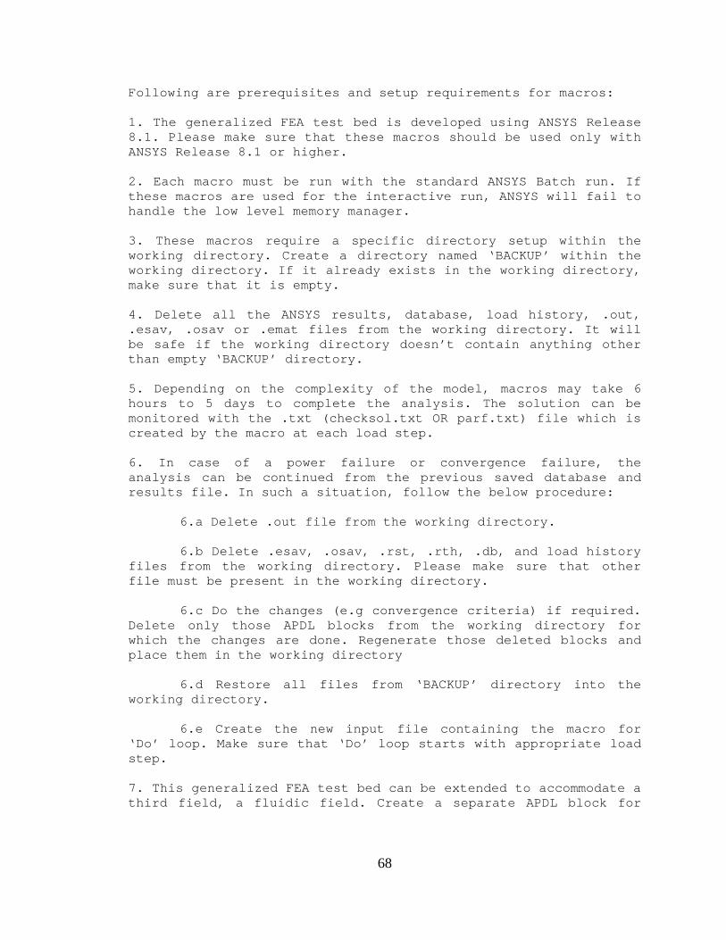
Following are prerequisites and setup requirements for macros: 1. The generalized FEA test bed is developed using ANSYS Release 8.1. Please make sure that these macros should be used only with ANSYS Release 8.1 or higher. 2. Each macro must be run with the standard ANSYS Batch run. If these macros are used for the interactive run, ANSYS will fail to handle the low level memory manager. 3. These macros require a specific directory setup within the working directory. Create a directory named ‘BACKUP’ within the working directory. If it already exists in the working directory, make sure that it is empty. 4. Delete all the ANSYS results, database, load history, .out, .esav, .osav or .emat files from the working directory. It will be safe if the working directory doesn’t contain anything other than empty ‘BACKUP’ directory. 5. Depending on the complexity of the model, macros may take 6 hours to 5 days to complete the analysis. The solution can be monitored with the .txt (checksol.txt OR parf.txt) file which is created by the macro at each load step. 6. In case of a power failure or convergence failure, the analysis can be continued from the previous saved database and results file. In such a situation, follow the below procedure: 6.a Delete .out file from the working directory. 6.b Delete .esav, .osav, .rst, .rth, .db, and load history files from the working directory. Please make sure that other file must be present in the working directory. 6.c Do the changes (e.g convergence criteria) if required. Delete only those APDL blocks from the working directory for which the changes are done. Regenerate those deleted blocks and place them in the working directory 6.d Restore all files from ‘BACKUP’ directory into the working directory. 6.e Create the new input file containing the macro for ‘Do’ loop. Make sure that ‘Do’ loop starts with appropriate load step. 7. This generalized FEA test bed can be extended to accommodate a third field, a fluidic field. Create a separate APDL block for
68
the fluidic field. (For e.g. STRUCTMODEL is for structural field, ELSTATMODEL for the electrostatic field) 8. To implement this FEA test bed for any other coupled electrostatic model, make appropriate changes in few blocks. In this case, other blocks can be used as they are.
SAVE,BACKUP\file,db /COPY,file,rst,,BACKUP\file,rst /COPY,file,esav,,BACKUP\file,esav /COPY,file,emat,,BACKUP\file,emat PARSAV,ALL,checksol,txt *ENDDO !*********************************** END OF MAIN PROGRAM *********************************** SAVE *DIM,datapl,TABLE,lstno-1,35,1, , , *MFUN,datapl(1,1),COPY,datastr_(2,1) /GROPT,VIEW,1 *VPLOT,datapl(1,3),datapl(1,14) /AXLAB,X,TIME /AXLAB,Y,GAP
*ENDIF PARSAV,ALL,checksol,txt *ENDDO !*********************************** END OF MAIN PROGRAM *********************************** /GROPT,view,1 *DIM,datapl,TABLE,lstno-1,35,1, , , *MFUN,datapl(1,1),COPY,datastr_(1,1) *VPLOT,datapl(1,3),datapl(1,9) /AXLAB,X,TIME /AXLAB,Y,C. G. GAP
*set,extnprev,'s0%cnt-1%' *IF,cnt,GT,10,THEN *set,extnprev,'s%cnt-1%' *ENDIF /DELETE,BACKUP\file,db /DELETE,BACKUP\field1,rst /DELETE,BACKUP\field1,esav /DELETE,BACKUP\field2,esav /DELETE,BACKUP\field1,emat /DELETE,BACKUP\field2,emat /DELETE,BACKUP\file,extnprev /DELETE,file,extnprev SAVE,BACKUP\file,db /COPY,field1,rst,,BACKUP\field1,rst /COPY,field1,esav,,BACKUP\field1,esav /COPY,field2,esav,,BACKUP\field2,esav /COPY,field1,emat,,BACKUP\field1,emat /COPY,field2,emat,,BACKUP\field2,emat /COPY,file,extn,,BACKUP\file,extn PARSAV,ALL,checksol,txt *ENDDO !*********************************** END OF MAIN PROGRAM *********************************** SAVE *DIM,datapl,TABLE,lstno-1,35,1, , , *MFUN,datapl(1,1),COPY,datastr_(1,1) /GROPT,VIEW,1 *VPLOT,datapl(1,3),datapl(1,8) /AXLAB,X,TIME /AXLAB,Y, CENTER GAP
187
APPENDIX J
JOURNAL AND CONFERENCE PUBLICATIONS
WHERE THIS WORK IS UITLIZED
188
189
190
191
192
193
194
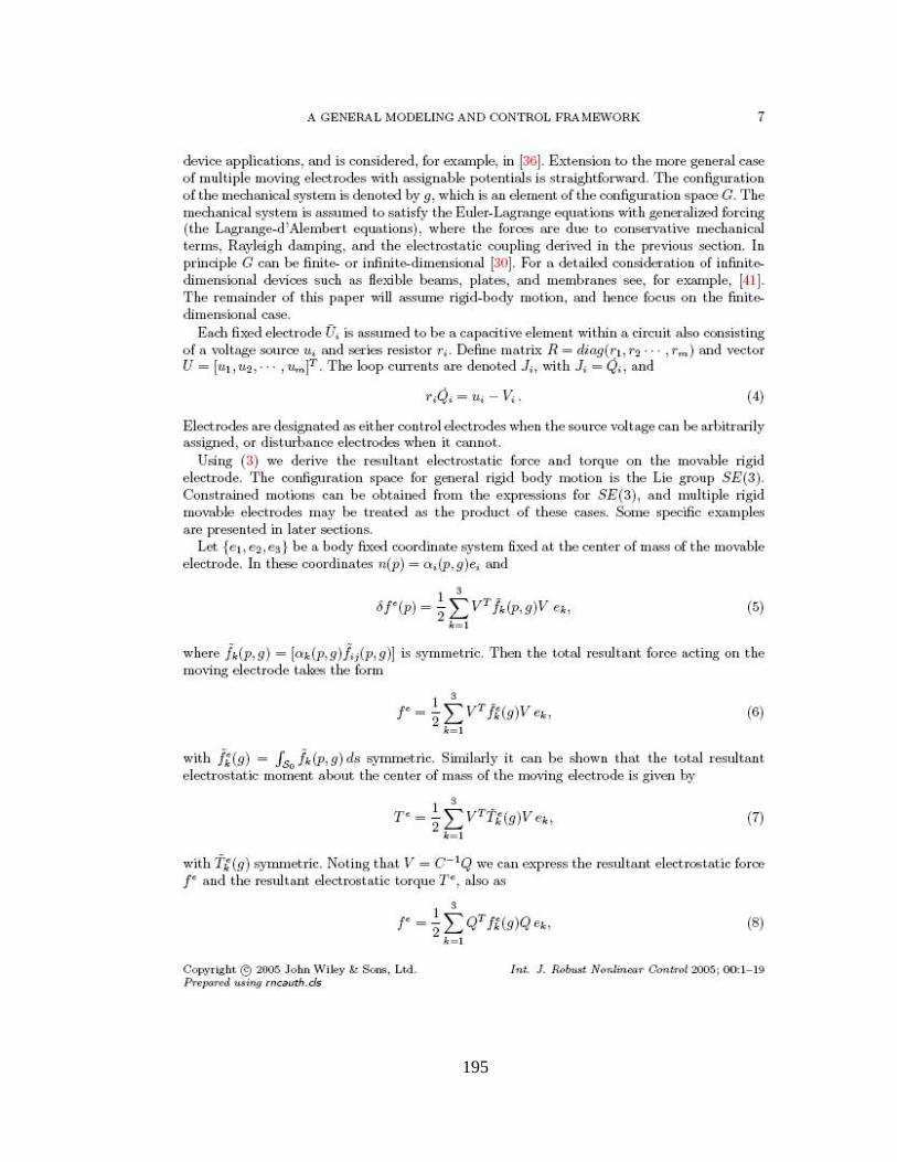
195
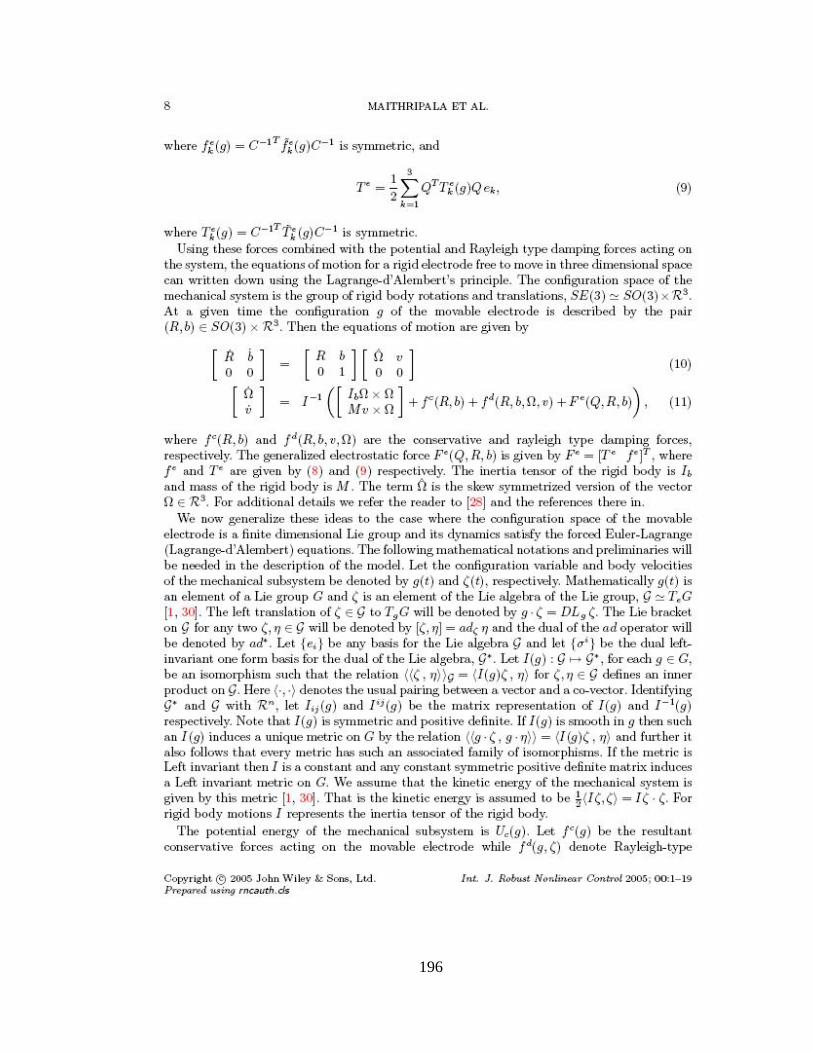
196
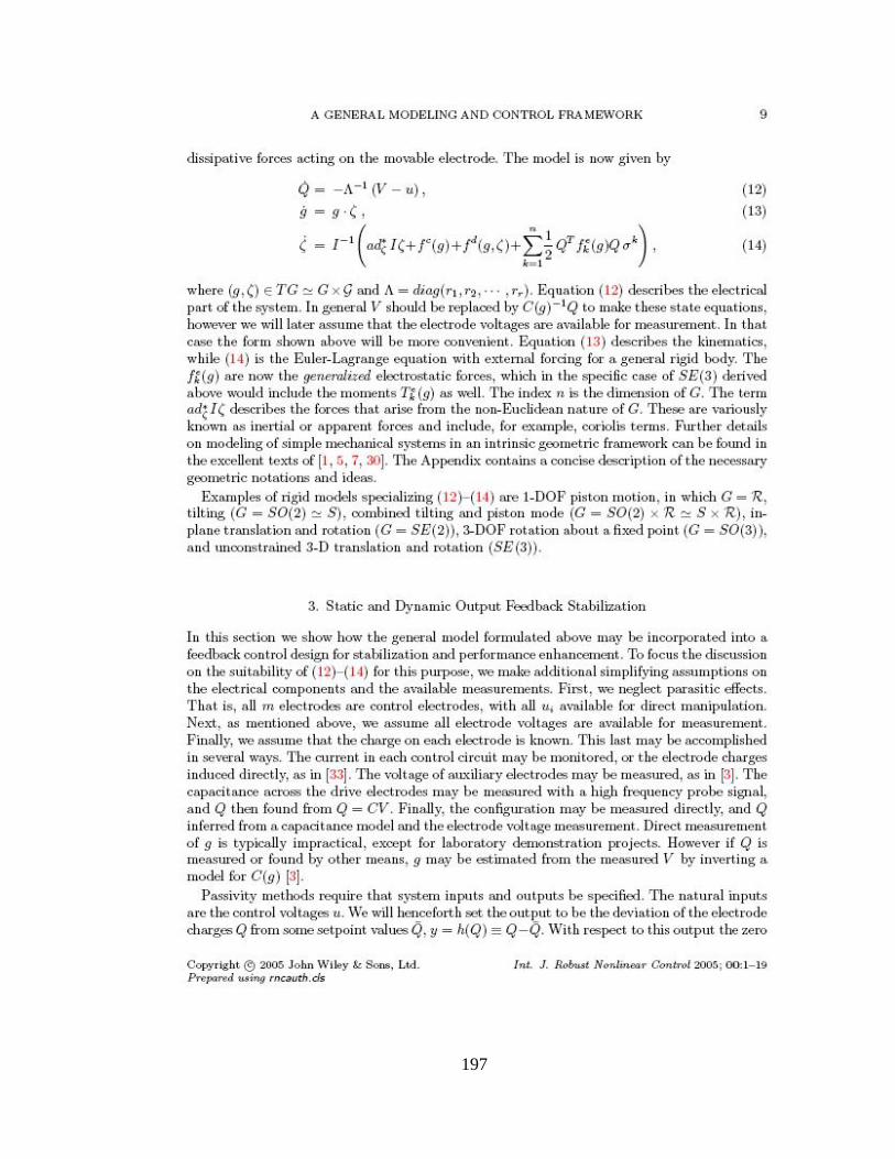
197
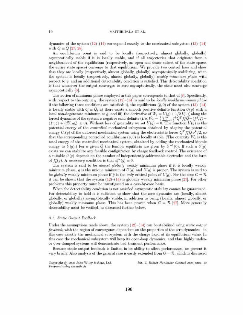
198
199
200
201
202
203
204
205
206
207
208
209
210
211
212
213
214
215
216
217
PERMISSION TO COPY
In presenting this thesis in partial fulfillment of the requirements for a master’s
degree at Texas Tech University or Texas Tech University Health Sciences Center, I
agree that the Library and my major department shall make it freely available for research
purposes. Permission to copy this thesis for scholarly purposes may be granted by the
Director of the Library or my major professor. It is understood that any copying or
publication of this thesis for financial gain shall not be allowed without my further
written permission and that any user may be liable for copyright infringement.
Agree (Permission is granted.)
_____Balasaheb D. Kawade________________________ __11/23/2005______ Student Signature Date Disagree (Permission is not granted.) _______________________________________________ _________________ Student Signature Date