ETSI EN 301 908-5 V5.2.1 (2011-09) IMT cellular networks; Harmonized EN covering the essential requirements of article 3.2 of the R&TTE Directive; Part 5: CDMA Multi-Carrier (cdma2000) Base Stations (BS) Harmonized European Standard
Transcript
ETSI EN 301 908-5 V5.2.1 (2011-09)
IMT cellular networks; Harmonized EN covering the essential requirements
of article 3.2 of the R&TTE Directive; Part 5: CDMA Multi-Carrier (cdma2000) Base Stations (BS)
Harmonized European Standard
ETSI
ETSI EN 301 908-5 V5.2.1 (2011-09) 2
Reference REN/MSG-TFES-007-5
Keywords 3G, 3GPP2, cdma2000, cellular, digital,
IMT-2000, mobile, radio, regulation, UMTS
ETSI
650 Route des Lucioles F-06921 Sophia Antipolis Cedex - FRANCE
Tel.: +33 4 92 94 42 00 Fax: +33 4 93 65 47 16
Siret N° 348 623 562 00017 - NAF 742 C
Association à but non lucratif enregistrée à la Sous-Préfecture de Grasse (06) N° 7803/88
Important notice
Individual copies of the present document can be downloaded from: http://www.etsi.org
The present document may be made available in more than one electronic version or in print. In any case of existing or perceived difference in contents between such versions, the reference version is the Portable Document Format (PDF).
In case of dispute, the reference shall be the printing on ETSI printers of the PDF version kept on a specific network drive within ETSI Secretariat.
Users of the present document should be aware that the document may be subject to revision or change of status. Information on the current status of this and other ETSI documents is available at
http://portal.etsi.org/tb/status/status.asp
If you find errors in the present document, please send your comment to one of the following services: http://portal.etsi.org/chaircor/ETSI_support.asp
Copyright Notification
No part may be reproduced except as authorized by written permission. The copyright and the foregoing restriction extend to reproduction in all media.
DECTTM, PLUGTESTSTM, UMTSTM and the ETSI logo are Trade Marks of ETSI registered for the benefit of its Members. 3GPPTM and LTE™ are Trade Marks of ETSI registered for the benefit of its Members and
of the 3GPP Organizational Partners. GSM® and the GSM logo are Trade Marks registered and owned by the GSM Association.
Intellectual Property Rights ................................................................................................................................ 6
4.2.2.2.1 Macro cell base station .................................................................................................................... 24
4.2.2.2.2 Pico cell base station and femto cell ................................................................................................ 26
4.2.3 Maximum output power .............................................................................................................................. 28
5.1.2 Standard equipment under test .................................................................................................................... 32
5.2 Interpretation of the measurement results ........................................................................................................ 32
5.3 Essential radio test suites .................................................................................................................................. 32
5.3.1.1 Test procedure for Base Stations supporting operation in Type 1 cdma2000 systems ......................... 33
5.3.1.1.1 Macro cell base station .................................................................................................................... 33
5.3.1.1.2 Pico cell base station and femto cell ................................................................................................ 33
5.3.1.2 Test procedure for Base Stations supporting operation in Type 2 cdma2000 systems ......................... 35
5.3.1.2.1 Macro cell base station .................................................................................................................... 35
5.3.1.2.2 Pico cell base station and femto cell ................................................................................................ 36
5.3.2 Maximum output power .............................................................................................................................. 38
5.3.2.1 Test procedure for Base Stations supporting operation in Type 1 cdma2000 systems ......................... 38
5.3.2.2 Test procedure for Base Stations supporting operation in Type 2 cdma2000 systems ......................... 39
5.3.3 Inter-Base Station transmitter intermodulation ........................................................................................... 39
5.3.3.1 Test procedure for Base Stations supporting operation in Type 1 cdma2000 systems ......................... 39
5.3.3.2 Test procedure for Base Stations supporting operation in Type 2 cdma2000 systems 2 ...................... 39
5.3.7.1 Test procedure for Base Stations supporting operation in Type 1 cdma2000 systems ......................... 44
5.3.7.2 Test procedure for Base Stations supporting operation in Type 2 cdma2000 systems ......................... 45
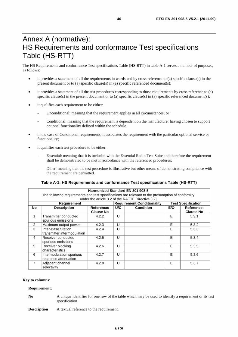
Annex A (normative): HS Requirements and conformance Test specifications Table (HS-RTT) ........................................................................................................ 46
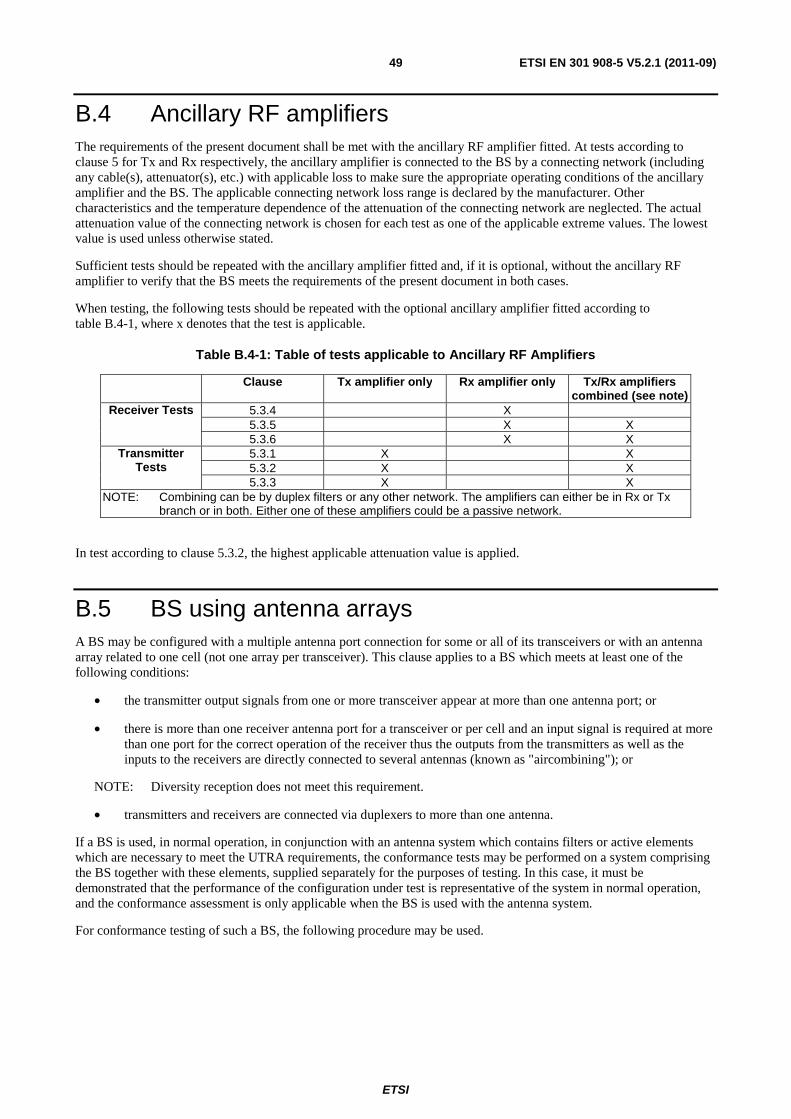
Annex B (normative): Base station Configurations .......................................................................... 48
C.2.1 Temperature and power supply voltage ............................................................................................................ 51
C.2.1.2 Method of measurement ............................................................................................................................. 51
C.2.1.3 Minimum standard ...................................................................................................................................... 52
C.2.2 High humidity .................................................................................................................................................. 52
C.2.2.2 Method of measurement ............................................................................................................................. 52
C.2.2.3 Minimum standard ...................................................................................................................................... 52
C.3 Standard test conditions.......................................................................................................................... 52
ETSI
ETSI EN 301 908-5 V5.2.1 (2011-09) 5
C.3.1 Standard environmental test conditions ............................................................................................................ 52
C.3.2 Standard conditions for the primary power supply ........................................................................................... 53
C.3.2.1 General ........................................................................................................................................................ 53
C.3.2.2 Standard DC test voltage from accumulator batteries ................................................................................. 53
C.3.2.3 Standard AC voltage and frequency ........................................................................................................... 53
Annex D (informative): The EN title in the official languages ........................................................... 54
Annex E (informative): Bibliography ................................................................................................... 55
History .............................................................................................................................................................. 56
ETSI
ETSI EN 301 908-5 V5.2.1 (2011-09) 6
Intellectual Property Rights IPRs essential or potentially essential to the present document may have been declared to ETSI. The information pertaining to these essential IPRs, if any, is publicly available for ETSI members and non-members, and can be found in ETSI SR 000 314: "Intellectual Property Rights (IPRs); Essential, or potentially Essential, IPRs notified to ETSI in respect of ETSI standards", which is available from the ETSI Secretariat. Latest updates are available on the ETSI Web server (http://ipr.etsi.org).
Pursuant to the ETSI IPR Policy, no investigation, including IPR searches, has been carried out by ETSI. No guarantee can be given as to the existence of other IPRs not referenced in ETSI SR 000 314 (or the updates on the ETSI Web server) which are, or may be, or may become, essential to the present document.
Foreword This Harmonized European Standard (EN) has been produced by ETSI Technical Committee Mobile Standards Group (MSG).
The present document has been produced by ETSI in response to mandate M/284 from the European Commission issued under Council Directive 98/34/EC [i.1] (as amended) laying down a procedure for the provision of information in the field of technical standards and regulations.
The title and reference to the present document are intended to be included in the publication in the Official Journal of the European Union of titles and references of Harmonized Standard under the Directive 1999/5/EC [i.2].
See article 5.1 of Directive 1999/5/EC [i.2] for information on presumption of conformity and Harmonised Standards or parts thereof the references of which have been published in the Official Journal of the European Union.
The requirements relevant to Directive 1999/5/EC [i.2] are summarised in annex A.
The present document is part 5 of a multi-part deliverable covering the essential requirements under article 3.2 of Directive 1999/5/EC [i.2] (R&TTE Directive) for Base Stations (BS), Repeaters and User Equipment (UE) for IMT cellular networks, as identified below:
Part 1: "Introduction and common requirements";
Part 2: "CDMA Direct Spread (UTRA FDD) User Equipment (UE)";
Part 3: "CDMA Direct Spread (UTRA FDD) Base Stations (BS)";
Part 4: "CDMA Multi-Carrier (cdma2000) User Equipment (UE)";
Part 5: "CDMA Multi-Carrier (cdma2000) Base Stations (BS)";
Part 6: "CDMA TDD (UTRA TDD) User Equipment (UE)";
Part 7: "CDMA TDD (UTRA TDD) Base Stations (BS)";
Part 8: "Harmonized EN for IMT-2000, TDMA Single-Carrier (UWC 136) (UE) covering essential requirements of article 3.2 of the R&TTE Directive";
Part 9: "Harmonized EN for IMT-2000, TDMA Single-Carrier (UWC 136) (BS) covering essential requirements of article 3.2 of the R&TTE Directive";
Part 10: "Harmonized EN for IMT-2000, FDMA/TDMA (DECT) covering essential requirements of article 3.2 of the R&TTE Directive";
Part 11: "CDMA Direct Spread (UTRA FDD) (Repeaters)";
Part 12: "Harmonized EN for IMT-2000, CDMA Multi-Carrier (cdma2000) (Repeaters) covering the essential requirements of article 3.2 of the R&TTE Directive";
Part 13: "Evolved Universal Terrestrial Radio Access (E-UTRA) User Equipment (UE)";
Part 14: "Evolved Universal Terrestrial Radio Access (E-UTRA) Base Stations (BS)";
Part 15: "Evolved Universal Terrestrial Radio Access (E-UTRA) (FDD Repeaters)";
Part 16: "Harmonized EN for IMT-2000, Evolved CDMA Multi-Carrier Ultra Mobile Broadband (UMB) (UE) covering the essential requirements of article 3.2 of the R&TTE Directive";
Part 17: "Harmonized EN for IMT-2000, Evolved CDMA Multi-Carrier Ultra Mobile Broadband (UMB) (BS) covering the essential requirements of article 3.2 of the R&TTE Directive";
Part 18: "E-UTRA, UTRA and GSM/EDGE Multi-Standard Radio (MSR) Base Stations (BS)";
Part 19: "OFDMA TDD WMAN (Mobile WiMAX) TDD User Equipment (UE)";
Part 20: "OFDMA TDD WMAN (Mobile WiMAX) TDD Base Station (BS)";
Part 21: "OFDMA TDD WMAN (Mobile WiMAX) FDD User Equipment (UE)";
Part 22: "OFDMA TDD WMAN (Mobile WiMAX) FDD Base Stations (BS)".
National transposition dates
Date of adoption of this EN: 12 September 2011
Date of latest announcement of this EN (doa): 31 December 2011
Date of latest publication of new National Standard or endorsement of this EN (dop/e):
30 June 2012
Date of withdrawal of any conflicting National Standard (dow): 30 June 2013
Introduction The present document is part of a set of standards developed by ETSI and is designed to fit in a modular structure to cover all radio and telecommunications terminal equipment within the scope of the R&TTE Directive [i.2]. The modular structure is shown in EG 201 399 [i.3].
ETSI
ETSI EN 301 908-5 V5.2.1 (2011-09) 8
1 Scope The present document applies to the following radio equipment types:
• Base stations for IMT-2000 CDMA multi-carrier (cdma2000) and Evolved CDMA Multi-Carrier Ultra Mobile Broadband (UMB).
These radio equipment types are capable of operating in all or any part of the frequency bands given in table 1-1.
Table 1-1: CDMA multi-carrier Base Station operating bands
Band Class (BC) Direction of transmission CDMA multi-carrier Base Station operating bands
6 Transmit 2 110 MHz to 2 170 MHz Receive 1 920 MHz to 1 980 MHz
8 Transmit 1 805 MHz to 1 880 MHz Receive 1 710 MHz to 1 785 MHz
9 Transmit 925 MHz to 960 MHz Receive 880 MHz to 915 MHz
13 Transmit 2 620 MHz to 2 690 MHz Receive 2 500 MHz to 2 570 MHz
The present document covers requirements for IMT-2000 CDMA multi-carrier (cdma2000) User Equipments and Evolved CDMA Multi-Carrier (UMB) User Equipment.
Base stations for IMT-2000 CDMA multi-carrier (cdma2000) may support:
1) operation in cdma2000 spread spectrum systems as defined in 3GPP2 C.S0002-E [2], referred to herein as operation in Type 1 cdma2000 systems; or
2) operation in cdma2000 High Rate Packet Data Systems as defined in 3GPP2 C.S0024-C [7] subtypes 0, 1, 2 and 3, referred to herein in Type 2 cdma2000 systems.
The present document is intended to cover the provisions of Directive 1999/5/EC [i.2] (R&TTE Directive) article 3.2, which states that "[…] radio equipment shall be so constructed that it effectively uses the spectrum allocated to terrestrial/space radio communications and orbital resources so as to avoid harmful interference".
In addition to the present document, other ENs that specify technical requirements in respect of essential requirements under other parts of article 3 of the R&TTE Directive [i.2] may apply to equipment within the scope of the present document.
NOTE: A list of such ENs is included on the web site http://www.newapproach.org/.
2 References References are either specific (identified by date of publication and/or edition number or version number) or non-specific. For specific references, only the cited version applies. For non-specific references, the latest version of the reference document (including any amendments) applies.
Referenced documents which are not found to be publicly available in the expected location might be found at http://docbox.etsi.org/Reference.
NOTE: While any hyperlinks included in this clause were valid at the time of publication ETSI cannot guarantee their long term validity.
2.1 Normative references The following referenced documents are necessary for the application of the present document.
[1] 3GPP2 C.S0010-D V1.0 (September 2010): "Recommended Minimum Performance Standards for cdma2000 Spread Spectrum Base Stations".
NOTE: Available at: http://www.3gpp2.org/Public_html/specs/C.S0010-D_v1.0_MPS_for_cdma2000_1x_BS.pdf.
[2] 3GPP2 C.S0002-E V2.0 (June 2010): "Physical Layer Standard for cdma2000 Spread Spectrum Systems Revision E".
NOTE: Available at: http://www.3gpp2.org/Public_html/specs/C.S0002-E_v2.0_cdma2000_1x_PHY.pdf.
[3] ANSI/TIA-98-F-1 (June 2006): "Recommended Minimum Performance Standards for cdma2000 Spread Spectrum Mobile Stations - Addendum".
[4] TIA/EIA-126-D (June 2001): "Loopback Service Options Standard (LSO) for cdma Spread Spectrum Systems".
[5] TIA-870-A (March 2005): "Test Data Service Option (TDSO) for cdma2000 Spread Spectrum Systems - Revision A".
[6] TIA-871-1 (October 2009): "Markov Service Option for cdma2000 Spread Spectrum Systems".
[7] 3GPP2 C.S0024-200-C V1.0 (April 2010): "Physical Layer for cdma2000 High Rate Packet Data Air Interface Specification".
NOTE: Available at: http://www.3gpp2.org/Public_html/specs/C.S0024-200-C_v1.0_HRPD_PHY.pdf.
[8] 3GPP2 C.S0032-C V1.0 (September 2010): "Recommended Minimum Performance Standards for cdma2000 High Rate Packet Data Access Network".
NOTE: Available at: http://www.3gpp2.org/Public_html/specs/C.S0032-C_v1.0_MPS_for_HRPD_AN.pdf.
[9] 3GPP2 C.S0029-B V1.0 (March 2008): "Test Application Specification (TAS) for High Rate Packet Data Air Interface".
NOTE: Available at: http://www.3gpp2.org/Public_html/specs/C.S0029-B_v1.0_080409.pdf.
[10] ETSI EN 301 908-1 (V5.2.1): "IMT cellular networks; Harmonized EN covering the essential requirements of article 3.2 of the R&TTE Directive; Part 1: Introduction and common requirements".
[11] ETSI EN 301 908-17 (V4.2.1): "Electromagnetic compatibility and Radio spectrum Matters (ERM); Base Stations (BS), Repeaters and User Equipment (UE) for IMT-2000 Third-Generation cellular networks; Part 17: Harmonized EN for IMT-2000, Evolved CDMA Multi-Carrier Ultra Mobile Broadband (UMB) (BS) covering the essential requirements of article 3.2 of the R&TTE Directive".
NOTE: Available at: http://www.3gpp2.org/Public_html/specs/X.S0059-100-0_v1.0_100216.pdf.
2.2 Informative references The following referenced documents are not necessary for the application of the present document but they assist the user with regard to a particular subject area.
[i.1] Directive 98/34/EC of the European Parliament and of the Council of 22 June 1998 laying down a procedure for the provision of information in the field of technical standards and regulations.
[i.2] Directive 1999/5/EC of the European Parliament and of the Council of 9 March 1999 on radio equipment and telecommunications terminal equipment and the mutual recognition of their conformity (R&TTE Directive).
[i.3] ETSI EG 201 399 (V2.1.1): "Electromagnetic compatibility and Radio spectrum Matters (ERM); A guide to the production of candidate Harmonized Standards for application under the R&TTE Directive".
3 Definitions, symbols and abbreviations
3.1 Definitions For the purposes of the present document, the following terms and definitions apply:
1X: mode of operation of a Base Station or access network using spreading rate 1
1XDO: mode of operation of a Base Station or access network using spreading rate 1 in data optimized systems
3X: mode of operation of a Base Station using spreading rate 3
access attempt: sequence of one or more access probe sequences on the access channel or enhanced access channel containing the same message
NOTE: See also access probe, access probe sequence, and enhanced access probe.
access channel: reverse CDMA channel used by mobile stations for communicating to the Base Station
NOTE: The access channel is used for short signalling message exchanges, such as call originations, responses to pages, and registrations. The access channel is a slotted random access channel.
access channel preamble: preamble of an access probe consisting of a sequence of all-zero frames that is sent at the 4 800 bit/s rate
access network: network equipment providing data connectivity between a packet switched data network (typically the Internet) and the access terminals in Type 2 cdma2000 systems
NOTE: Connectivity is typically provided at the link layer (PPP). As used in the present document it is synonymous with Base Station except that HRPD access network always use spreading rate 1.
access probe: one access channel transmission consisting of a preamble and a message
NOTE: The transmission is an integer number of frames in length, and transmits one access channel message. See also access probe sequence and access attempt.
access probe sequence: sequence of one or more access probes on the access channel or enhanced access channel
NOTE: The same access channel or enhanced access channel message is transmitted in every access probe of an access attempt. See also access probe, enhanced access probe, and access attempt.
access terminal: device providing data connectivity to a user in Type 2 cdma2000 systems
NOTE: An access terminal may be connected to a computing device such as a laptop personal computer or may be self-contained data device such as a personal digital assistant or may be a mobile station. Also referred to as HRPD access terminal using spreading rate 1 or UE operating in a Type 2 cdma2000 system.
active frame: frame that contains data and, therefore, is enabled in terms of traffic power
additional preamble: preamble sent after the last fractional preamble on the reverse pilot channel, prior to transmitting on the enhanced access channel or on the reverse common control channel
adjacent channel leakage ratio: ratio of the on-channel transmit power to the power measured in one of the adjacent channels
ETSI
ETSI EN 301 908-5 V5.2.1 (2011-09) 11
bad frame: frame classified with insufficient frame quality or for radio configuration 19 600 bit/s primary traffic only, with bit errors
NOTE: See also good frame.
band class: set of frequency channels and a numbering scheme for these channels
NOTE: Band classes are defined in 3GPP2 C.S0010-D [1], clause 3.1, and ANSI/TIA-98 [3], clause 3.1.
Base Station (BS): fixed station used for communicating with mobile stations
NOTE 1: Base stations for IMT-2000 CDMA multi-carrier (cdma2000) may support, operation in cdma2000 spread spectrum systems as defined in 3GPP2 C.S0002-E [2], referred to herein as operation in Type 1 cdma2000 system, or operation in cdma2000 High Rate Packet Data Systems as defined in 3GPP2 C.S0024-200-C [7], referred to herein as operation in Type 2 cdma2000 systems.
NOTE 2: Depending upon the context, the term Base Station may refer to a cell, a sector within a cell, an MSC, and access network or other part of the wireless system. See also MSC.
basic access mode: mode used on the enhanced access channel where a mobile station transmits an enhanced access channel preamble and enhanced access data in a method similar to that used on the access channel
broadcast control channel: code channel in a forward CDMA channel used for transmission of control information from a Base Station to a mobile station
candidate frequency: frequency for which the Base Station specifies a search set, when searching on other frequencies while performing mobile-assisted handoffs
CDMA channel: set of channels transmitted from the Base Station and the mobile stations on a given frequency
CDMA channel number: 11-bit number corresponding to the centre of the CDMA frequency assignment
CDMA frequency assignment: 1,23 MHz segment of spectrum
NOTE: For band classes 6, 8, 9 and 13, the channel is centred on one of the 50 kHz channels.
CDMA preferred set: set of CDMA channel numbers in a CDMA system corresponding to frequency assignments that a mobile station will normally search to acquire a CDMA pilot channel
chip rate: rate of "chips" (modulated symbols after spreading) per second
code channel: subchannel of a forward CDMA channel or reverse CDMA channel. Each subchannel uses an orthogonal Walsh function or quasi-orthogonal function
Code Division Multiple Access (CDMA): technique for spread-spectrum multiple-access digital communications that creates channels through the use of unique code sequences
code symbol: output of an error-correcting encoder
NOTE 1: Information bits are input to the encoder and code symbols are output from the encoder.
NOTE 2: See convolutional code and turbo code.
common assignment channel: forward common channel used by the Base Station to acknowledge a mobile station accessing the enhanced access channel, and in the case of reservation access mode, to transmit the address of a reverse common control channel and associated common power control subchannel
common power control channel: forward common channel which transmits power control bits (i.e. common power control subchannels) to multiple mobile stations
NOTE: The common power control channel is used by mobile stations operating in the power controlled access mode, reservation access mode, or designated access mode.
common power control subchannel: subchannel on the common power control channel used by the Base Station to control the power of a mobile station when operating in the power controlled access mode on the enhanced access channel or when operating in the reservation access mode or the designated access mode on the reverse common control channel
ETSI
ETSI EN 301 908-5 V5.2.1 (2011-09) 12
continuous transmission: mode of operation in which discontinuous transmission is not permitted
convolutional code: type of error-correcting code
NOTE: A code symbol can be considered as the convolution of the input data sequence with the impulse response of a generator function.
cyclic redundancy code: class of linear error detecting codes which generate parity check bits by finding the remainder of a polynomial division
NOTE: See also frame quality indicator.
discontinuous transmission: mode of operation in which a Base Station or a mobile station switches its transmitter or a particular code channel on and off autonomously
NOTE: For the case of DTx operation on the forward dedicated control channel, the forward power control subchannel is still transmitted.
down-link: signal path where Base Station transmits and the mobile receives
NOTE: Also referred to as the forward link.
effective radiated power: product of the power supplied to the antenna and the antenna gain in a direction relative to a half-wave dipole
enhanced access channel: reverse channel used by the mobile for communicating to the Base Station
NOTE: The enhanced access channel operates in the basic access mode, power controlled access mode, and reservation access mode. It is used for transmission of short messages, such as signalling, MAC messages, response to pages, and call originations. It can also be used to transmit moderate-sized data packets.
enhanced access channel preamble: non-data-bearing portion of the enhanced access probe sent by the mobile station to assist the Base Station in initial acquisition and channel estimation
enhanced access data: data transmitted while in the basic access mode or power controlled access mode on the enhanced access channel or while in the reservation mode on a reverse common control channel
enhanced access header: frame containing access origination information transmitted immediately after the enhanced access channel preamble while in the power controlled access mode or reservation access mode
enhanced access probe: one enhanced access channel transmission consisting of an enhanced access channel preamble, optionally an enhanced access header, and optionally enhanced access data
enhanced access probe sequence: sequence of one or more enhanced access probes on the enhanced access channel
NOTE: See also enhanced access probe.
environmental profile: range of environmental conditions under which equipment within the scope of the present document is required to comply with the provisions of the present document
femto cell: base station that operates at a power level of less than or equal to +20 dBm, whose operation is authorized as a function of location by a femto management server as defined in 3GPP2 X.S0059-100-0 [12]
forward CDMA channel: CDMA channel from a Base Station to mobile stations
NOTE: The forward CDMA channel contains one or more code channels that are transmitted on a CDMA frequency assignment using a particular pilot PN offset.
forward common control channel: control channel used for the transmission of digital control information from a Base Station to one or more mobile stations
forward dedicated control channel: portion of a radio configuration 3 through 12 forward traffic channel used for the transmission of higher-level data, control information, and power control information from a Base Station to a mobile station
ETSI
ETSI EN 301 908-5 V5.2.1 (2011-09) 13
forward fundamental channel: portion of a forward traffic channel which carries a combination of higher-level data and power control information
forward MAC channel: forward channel used for medium access control in Type 2 cdma2000 systems
NOTE: Forward MAC channel consists of the reverse power control channels, the DRCLock channel and the reverse activity channel.
forward pilot channel: unmodulated, direct-sequence spread spectrum signal transmitted continuously by each CDMA Base Station
NOTE: The pilot channel allows a mobile station to acquire the timing of the forward CDMA channel, provides a phase reference for coherent demodulation, and provides means for signal strength comparisons between Base Stations for determining when to handoff.
forward power control subchannel: subchannel on the forward fundamental channel or forward dedicated control channel used by the Base Station to control the power of a mobile station when operating on the reverse traffic channel
forward supplemental channel: portion of a radio configuration 3 through 12 forward traffic channel which operates in conjunction with a forward fundamental channel or a forward dedicated control channel in that forward traffic channel to provide higher data rate services, and on which higher-level data is transmitted
forward supplemental code channel: portion of a radio configuration 1 and 2 forward traffic channel which operates in conjunction with a forward fundamental channel in that forward traffic channel to provide higher data rate services, and on which higher-level data is transmitted
forward test application protocol: test application protocol allowing forward link performance characterizations of Type 2 cdma2000 systems
NOTE: See 3GPP2 C.S0029-B [9].
forward traffic channel: one or more code channels used to transport user and signalling traffic from the Base Station to the mobile station
NOTE: See forward fundamental channel, forward dedicated control channel, forward supplemental channel, and forward supplemental code channel.
frame: basic timing interval in the system
NOTE: For the sync channel, a frame is 26,667 ms long. For the access channel, the paging channel, the broadcast channel, the forward supplemental code channel, and the reverse supplemental code channel, a frame is 20 ms long. For the forward supplemental channel and the reverse supplemental channel, a frame is 20 ms, 40 ms or 80 ms long. For the enhanced access channel, the forward common control channel, and the reverse common control channel, a frame is 5 ms, 10 ms or 20 ms long. For the forward fundamental channel, forward dedicated control channel, reverse fundamental channel, and reverse dedicated control channel, a frame is 5 ms or 20 ms long. For the common assignment channel, a frame is 5 ms long.
frame activity: ratio of the number of active frames to the total number of frames during channel operation
Frame Error Rate (FER): number of frames in error on the forward traffic channel divided by the total number of frames
NOTE: The value of Frame Error Rate may be estimated by using Service Option 2, 9, 32, 54 or 55 (see 3GPP2 C.S0010-D [1], clause 1.3).
frame quality indicator: CRC check applied to 9,6 kbit/s and 4,8 kbit/s traffic channel frames of radio configuration 1, to all forward traffic channel frames for radio configurations 2 through 9, to all reverse traffic channel frames for radio configurations 2 through 6, the broadcast channel, common assignment channel, enhanced access channel, and to the reverse common control channel
good frame: frame not classified as a bad frame
NOTE: See also bad frame.
good message: received message is declared a good message if it is received with a correct CRC
ETSI
ETSI EN 301 908-5 V5.2.1 (2011-09) 14
handoff: act of transferring communication with a mobile station from one Base Station to another
hard handoff: handoff characterized by a temporary disconnection of the traffic channel
NOTE: Hard handoffs occur when the mobile station is transferred between disjoint active sets, the CDMA frequency assignment changes, the frame offset changes, or the mobile station is directed from a CDMA traffic channel to an analog voice channel. See also soft handoff.
High Rate Packet Data: CDMA technique optimized for data communications in Type 2 cdma2000 systems
MAC channel: See forward MAC channel.
macro cell access network: access network that is not otherwise classified as a pico cell or femto cell. A macro cell can operate at any output power, including power levels below and equal to +24 dBm
macro cell base station: base station that is not otherwise classified as a pico cell base station or femto cell. A macro cell base station can operate at any output power, including power levels below and equal to +24 dBm
mean input power: total received calorimetric power measured in a specified bandwidth at the antenna connector, including all internal and external signal and noise sources
mean output power: total transmitted calorimetric power measured in a specified bandwidth at the antenna connector when the transmitter is active
mobile station: station intended to be used while in motion or during halts at unspecified points
NOTE: Mobile stations include portable units (e.g. hand-held personal units) and units installed in vehicles and HRPD access terminals.
mobile station class: mobile station classes define mobile station characteristics, such as slotted operation and transmission power
mobile switching centre: configuration of fixed equipment that provides cellular or PCS service
non-slotted mode: operation mode of the mobile station in which the mobile station continuously monitors the paging channel
orthogonal channel noise simulator: hardware mechanism used to simulate the users on the other orthogonal channels of a forward CDMA channel
orthogonal transmit diversity: forward link transmission method which distributes forward link channel symbols among multiple antennas and spreads the symbols with a unique Walsh or quasi-orthogonal function associated with each antenna
paging channel: code channel in a forward CDMA channel used for transmission of control information and pages from a Base Station to a mobile station
packet: physical layer protocol data unit
packet activity: ratio of the number of active frames to the total number of frames during channel operation in Type 2 cdma2000 systems
packet error: packet error event occurs when a decoded packet's FCS does not check
physical layer: part of the communication protocol between the mobile station and the Base Station that is responsible for the transmission and reception of data
NOTE: The physical layer in the transmitting station is presented a frame and transforms it into an over-the-air waveform. The physical layer in the receiving station transforms the waveform back into a frame.
pico cell access network: optional access network designation by the manufacturer that is permissible only when the maximum conducted output power is less than or equal to +24 dBm
pico cell base station: optional base station designation by the manufacturer that is permissible only when the maximum conducted output power is less than or equal to +24 dBm
ETSI
ETSI EN 301 908-5 V5.2.1 (2011-09) 15
piece-wise linear FER curve: FER - versus - Eb/Nt curve in which the FER vertical axis is in log scale and the Eb/Nt
horizontal axis is in linear scale expressed in dB, obtained by interpolating adjacent test data samples with straight lines
piece-wise linear MER curve: MER - versus - Eb/Nt curve in which the MER vertical axis is in log scale and the Eb/Nt
horizontal axis is in linear scale expressed in dB, obtained by interpolating adjacent test data samples with straight lines
pilot channel: unmodulated, direct-sequence spread spectrum signal transmitted by a CDMA Base Station or mobile station
NOTE: A pilot channel provides a phase reference for coherent demodulation and may provide a means for signal strength comparisons between Base Stations for determining when to handoff.
pilot PN sequence: pair of modified maximal length PN sequences used to spread the forward CDMA channel and the reverse CDMA channel
NOTE: Different Base Stations are identified by different pilot PN sequence offsets.
power control bit: bit sent in every 1,25 ms interval on the forward traffic channel, to signal the mobile station to increase or decrease its transmit power
power control group: 1,25 ms interval on the forward traffic channel and the reverse traffic channel
NOTE: See also power control bit.
power controlled access mode: mode used on the enhanced access channel where a mobile station transmits an enhanced Access preamble, an enhanced access header, and enhanced access data in the enhanced access probe using closed loop power control
power up function: method by which the mobile station increases its output power to support location services
preamble: See access channel preamble, enhanced access channel preamble, reverse common control channel preamble and reverse traffic channel preamble.
primary paging channel: default code channel (code channel 1) assigned for paging on a CDMA channel
PUF probe: one or more consecutive frames on the reverse traffic channel within which the mobile station transmits the PUF pulse
PUF pulse: portion of PUF probe which may be transmitted at elevated output power
PUF target frequency: CDMA frequency to which the Base Station directs a mobile station for transmitting the PUF probe
quick paging channel: uncoded, spread, and On-Off-Keying (OOK) modulated spread spectrum signal sent by a Base Station to inform mobile stations operating in the slotted mode during the idle state whether to receive the forward common control channel or the paging channel starting in the next forward common control channel or paging channel frame
radio configuration: set of forward traffic channel and reverse traffic channel transmission formats that are characterized by physical layer parameters such as transmission rates, modulation characteristics, and spreading rate
NOTE: Radio configurations are defined in 3GPP2 C.S0002-E [2], clauses 2.1.3 and 3.1.3.
received signal quality indicator: reverse traffic channel measure of signal quality related to the received Eb/N0
(see also Eb)
reservation access mode: mode used on the enhanced access channel and reverse common control channel where a mobile station transmits an enhanced access preamble and an enhanced access header in the enhanced access probe
NOTE: The enhanced access data is transmitted on a reverse common control channel using closed loop power control.
ETSI
ETSI EN 301 908-5 V5.2.1 (2011-09) 16
reverse CDMA channel: CDMA channel from the mobile station to the Base Station
NOTE: From the Base Station's perspective, the reverse CDMA channel is the sum of all mobile station transmissions on a CDMA frequency assignment.
reverse common control channel: portion of a reverse CDMA channel used for the transmission of digital control information from one or more mobile stations to a Base Station
NOTE: The reverse common control channel can operate in a reservation access mode or designated access mode. It can be power controlled in the reservation access mode or designated access mode, and may support soft handoff in the reservation access mode.
reverse common control channel preamble: non-data bearing portion of the reverse common control channel sent by the mobile station to assist the Base Station in initial acquisition and channel estimation
reverse dedicated control channel: portion of a radio configuration 3 through 8 reverse traffic channel used for the transmission of higher-level data and control information from a mobile station to a Base Station
reverse fundamental channel: portion of a reverse traffic channel which carries higher-level data and control information from a mobile station to a Base Station
reverse pilot channel: unmodulated, direct-sequence spread spectrum signal transmitted continuously by a CDMA mobile station
NOTE: A reverse pilot channel provides a phase reference for coherent demodulation and may provide a means for signal strength measurement.
reverse power control subchannel: subchannel on the reverse pilot channel used by the mobile station to control the power of a Base Station when operating on the forward traffic channel with radio configurations 3 through 9
reverse supplemental channel: portion of a radio configuration 3 through 8 reverse traffic channel which operates in conjunction with the reverse fundamental channel or the reverse dedicated control channel in that reverse traffic channel to provide higher data rate services, and on which higher-level data is transmitted
reverse supplemental code channel: portion of a radio configuration 1 and 2 reverse traffic channel which operates in conjunction with the reverse fundamental channel in that reverse traffic channel, and (optionally) with other reverse supplemental code channels to provide higher data rate services, and on which higher-level data is transmitted
reverse test application protocol: test application protocol allowing reverse link performance characterizations in Type 2 cdma2000 systems
reverse traffic channel: traffic channel on which data and signalling are transmitted from a mobile station to a Base Station
NOTE: The reverse traffic channel is composed of up to one reverse dedicated control channel, up to one reverse fundamental channel, zero to two reverse supplemental channels, and zero to seven reverse supplemental code channels.
reverse traffic channel preamble: non-data bearing portion of the reverse pilot channel sent by the mobile station to aid the Base Station in initial acquisition and channel estimation for the reverse dedicated control channel and reverse fundamental channel
NOTE: See 3GPP2 C.S0029-B [9].
RF carrier: direct-sequence spread RF channel
NOTE: For the forward CDMA channel, the number of RF carriers is equal to the spreading rate; for the reverse CDMA channel, there is one RF carrier.
service option 2: loopback service option for radio configuration 1
NOTE: See TIA/EIA-126-D [4].
service option 9: loopback service option for radio configuration 2
NOTE: See TIA/EIA-126-D [4].
ETSI
ETSI EN 301 908-5 V5.2.1 (2011-09) 17
service option 30: mobile station data loopback test mode for Multiplex Option 1 supplemental channel
NOTE: See TIA/EIA-126-D [4].
service option 31: mobile station data loopback test mode for Multiplex Option 2 supplemental channel
NOTE: See TIA/EIA-126-D [4].
service option 32: test data service option for radio configurations 3 through 6 on the reverse traffic channel and radio configurations 3 through 9 on the forward traffic channel
NOTE: See TIA-870 [5].
service option 54: Markov service option for radio configurations 1 through 6 on the reverse traffic channel and radio configurations 1 through 9 on the forward traffic channel
NOTE: See TIA/EIA/IS-871-1 [6].
service option 55: loopback service option for radio configurations 1 through 6 on the reverse traffic channel and radio configurations 1 through 9 on the forward traffic channel
NOTE: See TIA/EIA-126-D [4].
serving frequency: CDMA frequency on which a mobile station is currently communicating with one or more Base Stations
slot: duration of time specified by 1,6 ms
slotted mode: operation mode of the mobile station in which the mobile station monitors only selected slots on the paging channel
soft handoff: handoff occurring while the mobile station is in the mobile station control on the traffic channel state
NOTE: This handoff is characterized by commencing communications with a new Base Station on the same CDMA frequency assignment before terminating communications with the old Base Station. See hard handoff.
space time spreading: forward link transmission method which transmits all forward link channel symbols on multiple antennas and spreads the symbols with complementary Walsh or quasi-orthogonal functions
spreading rate: PN chip rate of the forward CDMA channel or the reverse CDMA channel, defined as a multiple of 1,2288 Mcps
spreading rate 1: often referred to as "1X"
NOTE 1: A spreading rate 1 forward CDMA channel uses a single direct-sequence spread carrier with a chip rate of 1,2288 Mcps.
NOTE 2: A spreading rate 1 reverse CDMA channel uses a single direct-sequence spread carrier with a chip rate of 1,2288 Mcps.
spreading rate 3: often referred to as "3X"
NOTE 1: A spreading rate 3 forward CDMA channel uses three direct-sequence spread carriers (see multiple-carrier forward channel) each with a chip rate of 1,2288 Mcps.
NOTE 2: A spreading rate 3 reverse CDMA channel uses a single direct-sequence spread carrier with a chip rate of 3,6864 Mcps.
symbol: See code symbol and modulation symbol.
sync channel: code channel 32 in the forward CDMA channel, which transports the synchronization message to the mobile station
ETSI
ETSI EN 301 908-5 V5.2.1 (2011-09) 18
system time: time reference used by the system
NOTE: System time is synchronous to UTC time (except for leap seconds) and uses the same time origin as Global Positioning System (GPS) time. All Base Stations use the same system time (within a small error). Mobile stations use the same system time, offset by the propagation delay from the Base Station to the mobile station. See also Universal Co-ordinated Time.
time reference: reference established by the mobile station that is synchronous with the earliest arriving multipath component used for demodulation
traffic channel: communication path between a mobile station and a Base Station used for user and signalling traffic
NOTE: The term traffic channel implies a forward traffic channel and reverse traffic channel pair. See also forward traffic channel and reverse traffic channel.
transmit diversity pilot channel: unmodulated, direct-sequence spread spectrum signal transmitted continuously by a CDMA Base Station to support forward link transmit diversity
NOTE: The pilot channel and the transmit diversity pilot channel provide phase references for coherent demodulation of forward link CDMA channels which employ transmit diversity.
turbo code: type of error-correcting code
NOTE: A code symbol is based on the outputs of the two recursive convolutional codes (constituent codes) of the turbo code.
Type 1 cdma2000 systems: cdma2000 spread spectrum systems
NOTE: See 3GPP2 C.S0002-E [2].
Type 2 cdma2000 systems: cdma2000 High Rate Packet Data systems
NOTE: See 3GPP2 C.S0024-200-C [7].
universal coordinated time: internationally agreed-upon time scale maintained by the Bureau International de l'Heure (BIH) used as the time reference by nearly all commonly available time and frequency distribution systems, e.g. WWV, WWVH, LORAN-C, Transit, Omega and GPS
up-link: signal path where the mobile transmits and the Base Station receives
NOTE: Also referred to as the reverse link.
user equipment: mobile station supporting operation in cdma2000 spread spectrum systems
NOTE: See 3GPP2 C.S0002-E [2], referred to herein as operation in Type 1 cdma2000 system; access terminal supporting operation in cdma2000 High Rate Packet Data Systems as defined in 3GPP2 C.S0024-200-C [7], referred to herein as operation in Type 2 cdma2000 system; and mobile station supporting operation in Type 1 and Type 2 cdma2000 systems.
valid power control bit: valid power control bit is sent on the forward traffic channel in the second power control group following the corresponding reverse traffic channel power control group which was not gated off and in which the signal was estimated
NOTE: See 3GPP2 C.S0002-E [2], clause 3.1.3.1.10.
walsh function: one of 2N time orthogonal binary functions
NOTE: The functions are orthogonal after mapping "0" to 1 and "1" to -1.
ETSI
ETSI EN 301 908-5 V5.2.1 (2011-09) 19
3.2 Symbols For the purposes of the present document, the following symbols apply:
Ω Ohm Δf Separation between the carrier centre frequency and the nominal -3 dB point of the measuring
filter closest to the carrier frequency bit/s bits per second
orI
cE BCCH ratio of the average transmit energy-per-PN energy-per-PNchip for the broadcast control channel
to the total transmit power spectral density dBc ratio (in dB) of the sideband power of a signal, measured in a given bandwidth at a given
frequency offset from the centre frequency of the same signal, to the total inband power of the signal. For CDMA, the total inband power of the signal is measured in a 1,23 MHz bandwidth around the centre frequency of the CDMA signal for a spreading rate 1 CDMA signal and in 3,69 MHz bandwidth around the centre frequency of the CDMA signal for a spreading rate 3 CDMA signal
dBm measure of power expressed in terms of its ratio (in dB) to 1 mW
dBm/Hz measure of power spectral density. The ratio, dBm/Hz, is the power in 1 Hz of bandwidth, where power is expressed in units of dBm
Eb combined energy per bit at the Base Station RF input port or the mobile station antenna connector
NOTE: For radio configurations 1 and 2, this is the received energy of the access channel or traffic channel. For the enhanced access channel with radio configurations 3 through 8, this is the combined energy of the enhanced access channel and the reverse pilot channel. For the reverse common control channel with radio configurations 3 through 8, this is the combined energy of the reverse common control channel and the reverse pilot channel. For the reverse traffic channel with radio configurations 3 through 8, this is the combined energy of the reverse traffic channel, the reverse pilot channel, and the reverse power control subchannel. See also Eb/N0.
Eb/N0 ratio in dB of the combined received energy per bit to the total received noise-plus-interference
power in the received CDMA bandwidth divided by 1,23 MHz for spreading rate 1 and 3,69 MHz for spreading rate 3 (see also Eb)
Eb/Nt ratio in dB of the combined received energy per bit to the effective noise power spectral density
Ec average energy accumulated over one PN chip period
Ec/Ior ratio in dB between the energy accumulated over one PN chip period (Ec) to the total transmit power spectral density
Ec/Io ratio in dB between the pilot energy accumulated over one PN chip period (Ec) to the total power
spectral density (Io) in the received bandwidth
orI
cE FCACH
ratio of the average transmit energy-per-PN chip for the forward common assignment channel to
the total transmit power spectral density
orI
cE FCCCH
ratio of the average transmit energy-per-PN chip for the forward common control channel to the
total transmit power spectral density
orI
cE FCPCCH ratio of the average transmit energy-per-PN chip for the forward common power control channel
to the total transmit power spectral density
ETSI
ETSI EN 301 908-5 V5.2.1 (2011-09) 20
GHz GigaHertz (109 Hertz)
Io total received power spectral density, including signal and interference, as measured at the mobile or Base Station antenna connector
Ioc power spectral density of a band-limited white noise source (simulating interference from other cells) as measured at the mobile station antenna connector. For test cases where multiple channels or cells are specified, this power spectral density does not include power from these multiple channels or cells
Ior total transmit power spectral density of the forward CDMA channel at the Base Station antenna
connector. For transmit diversity test cases, it shall be the total combined transmit power spectral density of the forward CDMA channel from both the main and transmit diversity Base Station antenna connectors
Îor received power spectral density of the forward CDMA channel as measured at the mobile station antenna connector
kHz kiloHertz (103 Hertz)
mbar millibar (10-3 Bar)
MHz MegaHertz (106 Hertz)
Mcps Megachips per second (106 chips per second)
µs microsecond (10-6 second)
ms millisecond (10-3 second)
ns nanosecond (10-9 second)
N0 effective inband noise or interference power spectral density
OCNS Ec average energy-per-PN chip for the OCNS
orI
cE OCNS ratio of the average transmit energy-per-PN chip for the OCNS to the total transmit power spectral
density
Pa Pascal
Paging Ec average energy-per-PN chip for the paging channel
orI
cE Paging ratio of the average transmit energy-per-PN chip for the paging channel to the total transmit power
spectral density
Pilot Ec average energy-per-PN chip for the pilot channel
Pilot oI
cE ratio of the combined pilot energy per chip, Ec, to the total received power spectral density (noise
and signals), Io, of at most K usable multipath components at the mobile station antenna connector.
K is the number of demodulating elements supported by the mobile station
orI
cEPilot ratio of the average transmit energy-per-PN chip for the pilot channel to the total transmit power
spectral density
ETSI
ETSI EN 301 908-5 V5.2.1 (2011-09) 21
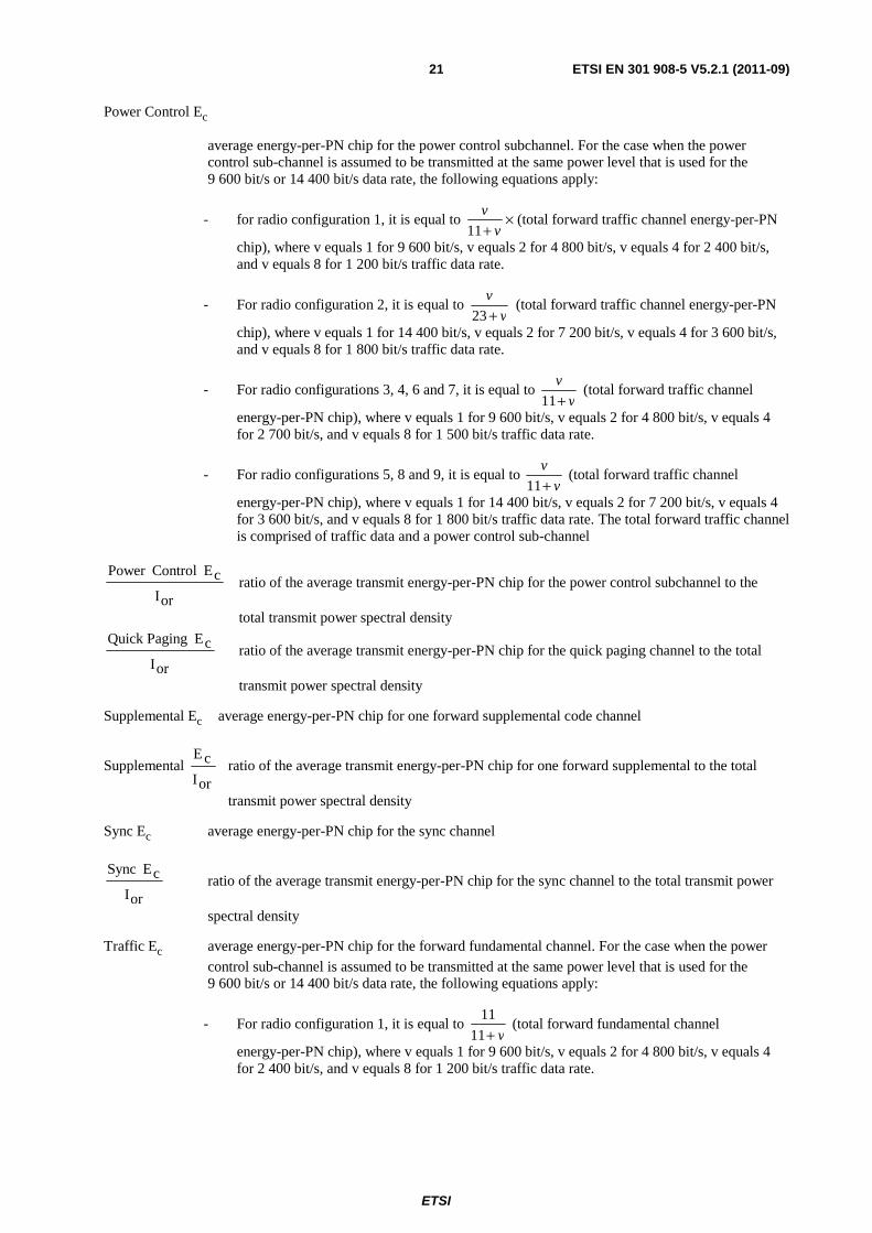
Power Control Ec
average energy-per-PN chip for the power control subchannel. For the case when the power control sub-channel is assumed to be transmitted at the same power level that is used for the 9 600 bit/s or 14 400 bit/s data rate, the following equations apply:
- for radio configuration 1, it is equal to v
v
+11× (total forward traffic channel energy-per-PN
chip), where v equals 1 for 9 600 bit/s, v equals 2 for 4 800 bit/s, v equals 4 for 2 400 bit/s, and v equals 8 for 1 200 bit/s traffic data rate.
- For radio configuration 2, it is equal to v
v
+23 (total forward traffic channel energy-per-PN
chip), where v equals 1 for 14 400 bit/s, v equals 2 for 7 200 bit/s, v equals 4 for 3 600 bit/s, and v equals 8 for 1 800 bit/s traffic data rate.
- For radio configurations 3, 4, 6 and 7, it is equal to v
v
+11 (total forward traffic channel
energy-per-PN chip), where v equals 1 for 9 600 bit/s, v equals 2 for 4 800 bit/s, v equals 4 for 2 700 bit/s, and v equals 8 for 1 500 bit/s traffic data rate.
- For radio configurations 5, 8 and 9, it is equal to v
v
+11 (total forward traffic channel
energy-per-PN chip), where v equals 1 for 14 400 bit/s, v equals 2 for 7 200 bit/s, v equals 4 for 3 600 bit/s, and v equals 8 for 1 800 bit/s traffic data rate. The total forward traffic channel is comprised of traffic data and a power control sub-channel
orI
cE ControlPower ratio of the average transmit energy-per-PN chip for the power control subchannel to the
total transmit power spectral density
orI
cE PagingQuick ratio of the average transmit energy-per-PN chip for the quick paging channel to the total
transmit power spectral density
Supplemental Ec average energy-per-PN chip for one forward supplemental code channel
Supplemental orI
cE ratio of the average transmit energy-per-PN chip for one forward supplemental to the total
transmit power spectral density
Sync Ec average energy-per-PN chip for the sync channel
orI
cE Sync ratio of the average transmit energy-per-PN chip for the sync channel to the total transmit power
spectral density
Traffic Ec average energy-per-PN chip for the forward fundamental channel. For the case when the power
control sub-channel is assumed to be transmitted at the same power level that is used for the 9 600 bit/s or 14 400 bit/s data rate, the following equations apply:
- For radio configuration 1, it is equal to v+11
11 (total forward fundamental channel
energy-per-PN chip), where v equals 1 for 9 600 bit/s, v equals 2 for 4 800 bit/s, v equals 4 for 2 400 bit/s, and v equals 8 for 1 200 bit/s traffic data rate.
ETSI
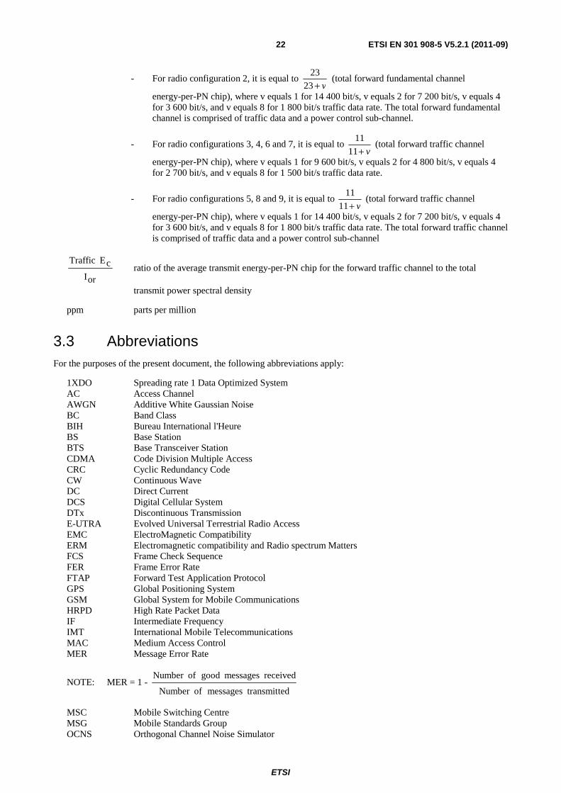
ETSI EN 301 908-5 V5.2.1 (2011-09) 22
- For radio configuration 2, it is equal to v+23
23 (total forward fundamental channel
energy-per-PN chip), where v equals 1 for 14 400 bit/s, v equals 2 for 7 200 bit/s, v equals 4 for 3 600 bit/s, and v equals 8 for 1 800 bit/s traffic data rate. The total forward fundamental channel is comprised of traffic data and a power control sub-channel.
- For radio configurations 3, 4, 6 and 7, it is equal to v+11
11 (total forward traffic channel
energy-per-PN chip), where v equals 1 for 9 600 bit/s, v equals 2 for 4 800 bit/s, v equals 4 for 2 700 bit/s, and v equals 8 for 1 500 bit/s traffic data rate.
- For radio configurations 5, 8 and 9, it is equal to v+11
11 (total forward traffic channel
energy-per-PN chip), where v equals 1 for 14 400 bit/s, v equals 2 for 7 200 bit/s, v equals 4 for 3 600 bit/s, and v equals 8 for 1 800 bit/s traffic data rate. The total forward traffic channel is comprised of traffic data and a power control sub-channel
orI
cE Traffic ratio of the average transmit energy-per-PN chip for the forward traffic channel to the total
transmit power spectral density
ppm parts per million
3.3 Abbreviations For the purposes of the present document, the following abbreviations apply:
1XDO Spreading rate 1 Data Optimized System AC Access Channel AWGN Additive White Gaussian Noise BC Band Class BIH Bureau International l'Heure BS Base Station BTS Base Transceiver Station CDMA Code Division Multiple Access CRC Cyclic Redundancy Code CW Continuous Wave DC Direct Current DCS Digital Cellular System DTx Discontinuous Transmission E-UTRA Evolved Universal Terrestrial Radio Access EMC ElectroMagnetic Compatibility ERM Electromagnetic compatibility and Radio spectrum Matters FCS Frame Check Sequence FER Frame Error Rate FTAP Forward Test Application Protocol GPS Global Positioning System GSM Global System for Mobile Communications HRPD High Rate Packet Data IF Intermediate Frequency IMT International Mobile Telecommunications MAC Medium Access Control MER Message Error Rate
NOTE: MER = 1 - ted transmitmessages ofNumber
received messages good ofNumber
MSC Mobile Switching Centre MSG Mobile Standards Group OCNS Orthogonal Channel Noise Simulator
ETSI
ETSI EN 301 908-5 V5.2.1 (2011-09) 23
OOK On-Off-Keying PCS Personal Communication System PER Packet Error Rate
NOTE: PER = 1 - ted transmitpackets ofNumber
received packets good ofNumber
PPP Point-to-Point Protocol PN PseudoNoise PUF Power Up Function R&TTE Radio and Telecommunications Terminal Equipment RA Reverse Activity RC Radio Configuration RF Radio Frequency RMS Root Mean Square RPC Reverse Power Control RTAP Reverse Test Application Protocol Rx Receiver TDD Time Division Duplex TFES Task Force for European Standards for IMT Tx Transmitter UE User Equipment UMB Ultra Mobile Broadband UTC Universal Time Coordinated UTRA Universal Terrestrial Radio Access
4 Technical requirements specifications
4.1 Environmental profile The technical requirements of the present document apply under the environmental profile for operation of the equipment, which shall be declared by the supplier. The equipment shall comply with all the technical requirements of the present document at all times when operating within the boundary limits of the declared operational environmental profile.
For guidance on how a supplier can declare the environmental profile see annex C.
4.2 Conformance requirements
4.2.1 Introduction
To meet the essential requirement under article 3.2 of Directive 1999/5/EC [i.2] (R&TTE Directive) for IMT-2000 Base Stations (BS) seven essential parameters in addition to those in EN 301 908-1 [10] have been identified. Table 4.2.1-1 provides a cross reference between these seven essential parameters and the seven corresponding technical requirements for equipment within the scope of the present document.
ETSI
ETSI EN 301 908-5 V5.2.1 (2011-09) 24
Table 4.2.1-1: Cross references
Essential parameter Corresponding technical requirements (see note) Spectrum emissions mask 4.2.2 Transmitter conducted spurious emissions Conducted spurious emissions from the transmitter antenna connector
4.2.2 Transmitter conducted spurious emissions
Accuracy of maximum output power 4.2.3 Maximum output power Intermodulation attenuation of the transmitter
4.2.4 Inter-Base Station transmitter intermodulation
Conducted spurious emissions from the receiver antenna connector
4.2.5 Receiver conducted spurious emissions
Impact of interference on receiver performance
4.2.6 Receiver blocking characteristics
4.2.7 Intermodulation spurious response attenuation Receiver adjacent channel selectivity 4.2.8 Adjacent channel selectivity NOTE: These technical requirements are all applicable for Base Station operation in
Type 1 cdma2000 spread spectrum systems as defined in 3GPP2 C.S0002-E [2], and for Base Station (access network) operation in Type 2 cdma2000 High Rate Packet Data Systems as defined in 3GPP2 C.S0024-200-C [7].
NOTE: Base stations operating in Type 2 cdma2000 High Rate Packet Data Systems as defined in 3GPP2 C.S0024-200-C [7], are also termed access networks in the present document. Access networks defined herein always use spreading rate 1 and are data optimized (1XDO).
The technical requirements in the present document apply for Base stations supporting Type 1 and Type 2 cdma2000 systems in the declared operating bands. Base stations supporting UMB shall fulfil the requirements in EN 301 908-17 [11].
4.2.2 Transmitter conducted spurious emissions
4.2.2.1 Definition
Conducted spurious emissions are emissions at frequencies that are outside the assigned CDMA Channel or HRPD channel, measured at the Base Station RF output port.
When operating in Type 2 cdma2000 systems, Base Station HRPD Channel conducted spurious emissions shall be measured for two test conditions:
• Case 1: continuous data mode (no idle slots).
• Case 2: idle mode (all idle slots, except the control channel).
NOTE: Inhibiting control channel transmissions is optional for case 2.
4.2.2.2 Limits
4.2.2.2.1 Macro cell base station
The spurious emissions shall be less than the limits specified in tables 4.2.2.2.1-1 to 4.2.2.2.1-4. The spurious emissions limits in tables 4.2.2.2.1-1 to 4.2.2.2.1-4 shall be met when transmitting on a single or all RF carriers supported by the Base Station and configured in accordance with the manufacturer's specification as indicated by the entries in the column "Active carriers".
ETSI
ETSI EN 301 908-5 V5.2.1 (2011-09) 25
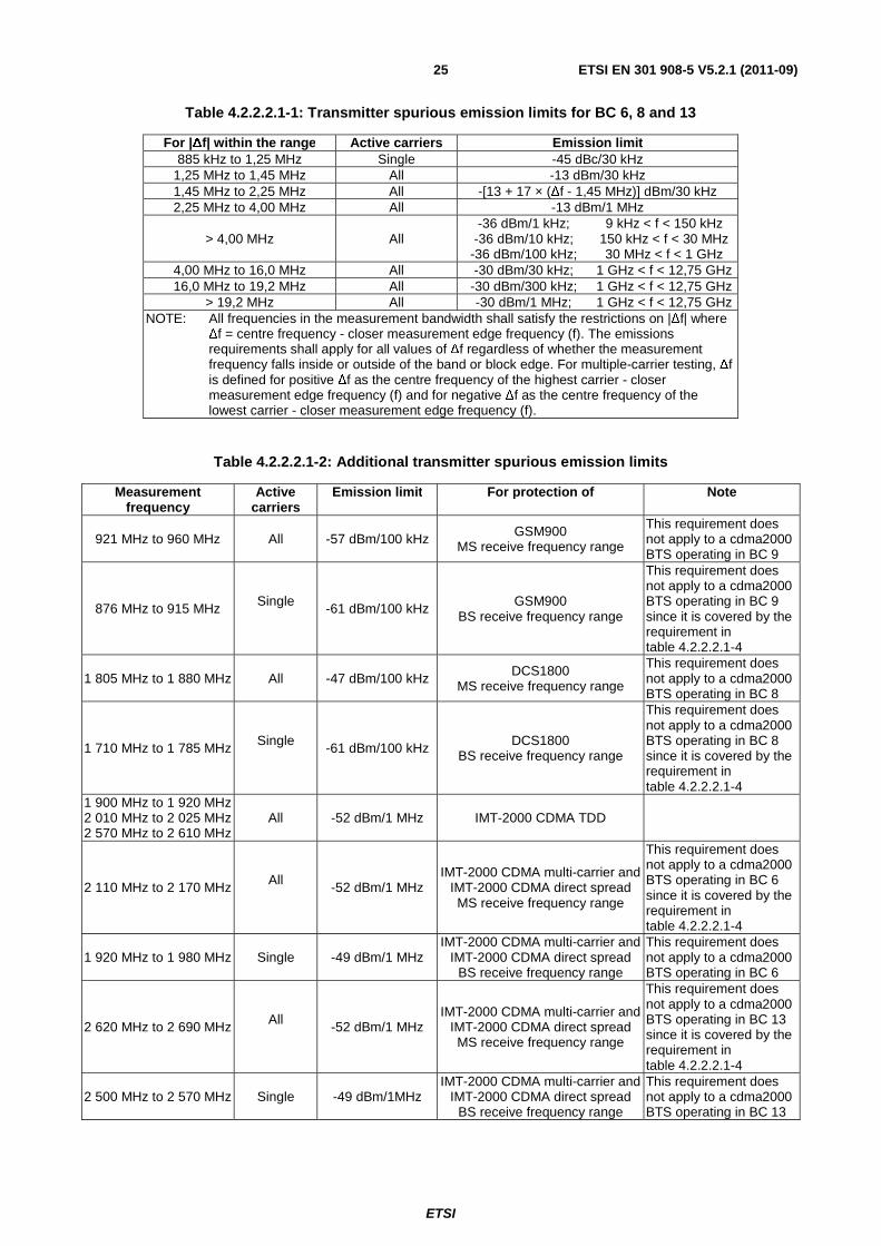
Table 4.2.2.2.1-1: Transmitter spurious emission limits for BC 6, 8 and 13
For |Δf| within the range Active carriers Emission limit 885 kHz to 1,25 MHz Single -45 dBc/30 kHz
1,25 MHz to 1,45 MHz All -13 dBm/30 kHz 1,45 MHz to 2,25 MHz All -[13 + 17 × (Δf - 1,45 MHz)] dBm/30 kHz 2,25 MHz to 4,00 MHz All -13 dBm/1 MHz
> 4,00 MHz All -36 dBm/1 kHz;
-36 dBm/10 kHz; -36 dBm/100 kHz;
9 kHz < f < 150 kHz 150 kHz < f < 30 MHz 30 MHz < f < 1 GHz
4,00 MHz to 16,0 MHz All -30 dBm/30 kHz; 1 GHz < f < 12,75 GHz 16,0 MHz to 19,2 MHz All -30 dBm/300 kHz; 1 GHz < f < 12,75 GHz
> 19,2 MHz All -30 dBm/1 MHz; 1 GHz < f < 12,75 GHz NOTE: All frequencies in the measurement bandwidth shall satisfy the restrictions on |Δf| where
Δf = centre frequency - closer measurement edge frequency (f). The emissions requirements shall apply for all values of Δf regardless of whether the measurement frequency falls inside or outside of the band or block edge. For multiple-carrier testing, Δf is defined for positive Δf as the centre frequency of the highest carrier - closer measurement edge frequency (f) and for negative Δf as the centre frequency of the lowest carrier - closer measurement edge frequency (f).
9 kHz < f < 150 kHz 150 kHz < f < 30 MHz 30 MHz < f < 1 GHz
1 GHz < f < 12,75 GHz 4,00 to 6,40 MHz Yes -36 dBm/1 kHz 30 MHz < f < 1 GHz 6,40 to 16 MHz Yes -36 dBm/10 kHz 30 MHz < f < 1 GHz
> 16 MHz Yes -36 dBm/100 kHz 30 MHz < f < 1 GHz NOTE: All frequencies in the measurement bandwidth shall satisfy the restrictions on |∆f| where ∆f = center
frequency, closer measurement edge frequency (f). The emissions requirements shall apply for all values of ∆f regardless of whether the measurement frequency falls inside or outside of the band or block edge. Compliance with the -46 dBm/6,25 kHz limit is based on the use of measurement instrumentation such that the reading taken with any resolution bandwidth setting should be adjusted to indicate spectral power in a 6,25 kHz segment. For multiple-carrier testing, ∆f is defined for positive ∆f as the center frequency of the highest carrier, closer measurement edge frequency (f) and for negative ∆f as the center frequency of the lowest carrier, closer measurement edge frequency (f).
Table 4.2.2.2.1-4: Spurious emissions limits for protection of a BS receiver
Operating band Band Emission Limit BC 6 1 920 MHz to 1 980 MHz -86 dBm/1 MHz BC 8 1 710 MHz to 1 785 MHz -86 dBm/1 MHz BC 9 880 MHz to 915 MHz -86 dBm/1 MHz
BC 13 2 500 MHz to 2 570 MHz -86 dBm/1 MHz
4.2.2.2.2 Pico cell base station and femto cell
The spurious emissions shall be less than the limits specified in tables 4.2.2.2.2-1 to 4.2.2.2.2-3. The spurious emissions limits in tables 4.2.2.2.2-1 to 4.2.2.2.2-3 shall be met when transmitting on a single or all RF carriers supported by the Base Station and configured in accordance with the manufacturer's specification as indicated by the entries in the column "Active carriers".
ETSI
ETSI EN 301 908-5 V5.2.1 (2011-09) 27
Table 4.2.2.2.2-1: BC 9 Transmitter Spurious Emission Limits
For |∆f| Within the Range
Applies to Multiple Carriers
Emission Limit
750 kHz to 1,98 MHz No -45 dBc / 30 kHz 1,98 MHz to 4,00 MHz No -55 dBc / 30 kHz 1,98 MHz to 2,25 MHz
(MC test only) Yes -25 dBm / 30 kHz
2,25 MHz to 4,00 MHz (MC test only)
Yes -26 dBm / 1 MHz
3,25 MHz to 4,00 MHz (Band Class 7 only) Yes -46 dBm / 6,25 kHz
> 4,00 MHz
Yes
-36 dBm / 1 kHz; -36 dBm / 10 kHz;
-46 dBm / 100 kHz; -36 dBm / 1 MHz;
9 kHz < f < 150 kHz 150 kHz < f < 30 MHz 30 MHz < f < 1 GHz
1 GHz < f < 12,5 GHz NOTE: All frequencies in the measurement bandwidth shall satisfy the restrictions on |∆f| .The
emissions requirements shall apply for all values of ∆f regardless of whether the measurement frequency falls inside or outside of the band or block edge. For single-carrier testing, ∆f = center frequency - closer measurement edge frequency (f). For multiple-carrier testing, ∆f is defined for positive ∆f as the closer measurement edge frequency (f) - center frequency of the highest carrier (F_high_test) and for negative ∆f as the closer measurement edge frequency (f) - center frequency of the lowest carrier (F_low_test).
Compliance with the -46 dBm / 6,25 kHz limit is based on the use of measurement instrumentation such that the reading taken with any resolution bandwidth setting should be adjusted to indicate spectral power in a 6,25 kHz segment.
Table 4.2.2.2.2-2: BC 6, 8 and 13 Transmitter Spurious Emission Limits
For |∆f| Within the Range Applies to Multiple Carriers
Emission Limit
885 kHz to 1,98 MHz No -45 dBc / 30 kHz 1,25 MHz to 2,25 MHz (MC
tests only) Yes -25 dBm / 30 kHz
1,98 MHz to 2,25 MHz No -55 dBc / 30 kHz 2,25 MHz to 4,00 MHz Yes -26 dBm / 1 MHz
9 kHz < f < 150 kHz 150 kHz < f < 30 MHz 30 MHz < f < 1 GHz
1 GHz < f < 12,5 GHz NOTE: All frequencies in the measurement bandwidth shall satisfy the restrictions on |∆f | where ∆f =
center frequency - closer measurement edge frequency (f). The emissions requirements shall apply for all values of ∆f regardless of whether the measurement frequency falls inside or outside of the band or block edge. The -9 dBm requirement is based on CFR 47 Part 24 -13 dBm/12,5 kHz specification. For multiple-carrier testing, ∆f is defined for positive ∆f as the closer measurement edge frequency (f) - center frequency of the highest carrier (F_high_test) and for negative ∆f as the closer measurement edge frequency (f) - center frequency of the lowest carrier (F_low_test).
ETSI
ETSI EN 301 908-5 V5.2.1 (2011-09) 28
Table 4.2.2.2.2-3: Additional BC 6 Transmitter Spurious Emission Limits
Measurement Frequency
Applies to Multiple Carriers
Emission Limit When Coverage Overlaps With
1 884,5 to 1 919,6 MHz No -41 dBm / 300 kHz PHS
824 to 849 MHz No -61 dBm / 100 kHz (non-colocated) GSM 850 CDMA 850
876 to 915 MHz No -61 dBm / 100 kHz (non-colocated) GSM 900 921 to 960 MHz Yes -57 dBm / 100 kHz GSM 900
1 710 to 1 785 MHz No -61 dBm / 100 kHz (non-colocated) DCS 1800 1 805 to 1 880 MHz Yes -47 dBm / 100 kHz DCS 1800
1 900 to 1 920 MHz and 2 010 to 2 025 MHz Yes -52 dBm / 1 MHz UTRA-TDD
1 920 to 1 980 MHz No - 86 dBm / 1 MHz Always
4.2.2.3 Conformance
Conformance tests described in clause 5.3.1 shall be carried out.
4.2.3 Maximum output power
4.2.3.1 Definition
Maximum output power is the mean power delivered to a load with resistance equal to the nominal load impedance of the transmitter.
Within each slot for Base Stations operating in Type 2 cdma2000 systems, the Pilot, MAC and Traffic or Traffic control channels shall be time-division multiplexed. All time-division multiplexed channels shall be transmitted at equal power. For Base Stations operating in Type 2 cdma2000 systems, this test measures the time response of the mean output power for non-idle slots and the mean power at the RF output port.
4.2.3.2 Limits
4.2.3.2.1 Base stations operating in Type 1 cdma2000 systems
The maximum output power shall remain within +2 dB and -4 dB of the manufacturer's rated power for the equipment.
The output power of Pico BS shall be less than or equal to +24 dBm.
The output power of Femto Cell not exceed +20 dBm average conducted power as measured at the RF output connector.
4.2.3.2.2 Base stations operating in Type 2 cdma2000 systems
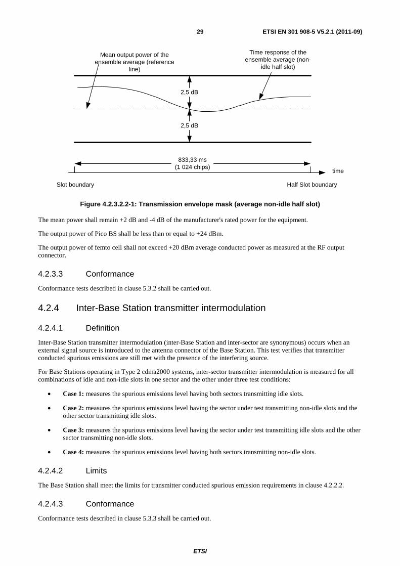
Given an ensemble of non-idle half slots, the time response of the ensemble average shall be within the limits shown in figure 4.2.3.2.2-1.
ETSI
ETSI EN 301 908-5 V5.2.1 (2011-09) 29
Slot boundary
2,5 dB
Time response of theensemble average (non-
idle half slot)
time
Half Slot boundary
2,5 dB
Mean output power of theensemble average (reference
The mean power shall remain +2 dB and -4 dB of the manufacturer's rated power for the equipment.
The output power of Pico BS shall be less than or equal to +24 dBm.
The output power of femto cell shall not exceed +20 dBm average conducted power as measured at the RF output connector.
4.2.3.3 Conformance
Conformance tests described in clause 5.3.2 shall be carried out.
4.2.4 Inter-Base Station transmitter intermodulation
4.2.4.1 Definition
Inter-Base Station transmitter intermodulation (inter-Base Station and inter-sector are synonymous) occurs when an external signal source is introduced to the antenna connector of the Base Station. This test verifies that transmitter conducted spurious emissions are still met with the presence of the interfering source.
For Base Stations operating in Type 2 cdma2000 systems, inter-sector transmitter intermodulation is measured for all combinations of idle and non-idle slots in one sector and the other under three test conditions:
• Case 1: measures the spurious emissions level having both sectors transmitting idle slots.
• Case 2: measures the spurious emissions level having the sector under test transmitting non-idle slots and the other sector transmitting idle slots.
• Case 3: measures the spurious emissions level having the sector under test transmitting idle slots and the other sector transmitting non-idle slots.
• Case 4: measures the spurious emissions level having both sectors transmitting non-idle slots.
4.2.4.2 Limits
The Base Station shall meet the limits for transmitter conducted spurious emission requirements in clause 4.2.2.2.
4.2.4.3 Conformance
Conformance tests described in clause 5.3.3 shall be carried out.
ETSI
ETSI EN 301 908-5 V5.2.1 (2011-09) 30
4.2.5 Receiver conducted spurious emissions
4.2.5.1 Definition
Conducted spurious emissions are spurious emissions generated or amplified in the Base Station equipment and appearing at the receiver RF input ports.
This requirement only applies if the Base Station is equipped with a separate RF input port.
4.2.5.2 Limits
The conducted spurious emissions shall be:
1) Less than -80 dBm, measured in a 30 kHz resolution bandwidth at the Base Station RF input ports, for frequencies within the Base Station receiver band (see table 1-1).
2) Less than -60 dBm, measured in a 30 kHz resolution bandwidth at the Base Station RF input ports, for frequencies within the Base Station transmit band (see table 1-1).
3) Less than -57 dBm, measured in a 100 kHz resolution bandwidth at the Base Station RF input ports, for frequencies from 30 MHz to 1 GHz with the exception of frequencies used by the BS between 4 MHz below the first carrier frequency and 4 MHz above the last carrier frequency when the BS is operating in spreading rate 1 mode, and 12,5 MHz below the first carrier frequency and 12,5 MHz above the last carrier frequency when the BS is operating in spreading rate 3 mode.
4) Less than -47 dBm, measured in a 1 MHz resolution bandwidth at the Base Station RF input ports, for all other frequencies in the range from 1 GHz to 12,75 GHz with the exception of frequencies used by the BS between 4 MHz below the first carrier frequency and 4 MHz above the last carrier frequency when the BS is operating in spreading rate 1 mode, and 12,5 MHz below the first carrier frequency and 12,5 MHz above the last carrier frequency when the BS is operating in spreading rate 3 mode.
NOTE: HRPD access networks, BS operating in Type 2 cdma2000 systems, always use spreading rate 1.
4.2.5.3 Conformance
Conformance tests described in clause 5.3.4 shall be carried out.
4.2.6 Receiver blocking characteristics
4.2.6.1 Definition
Receiver blocking is a measure of the ability to receive a CDMA signal or an HRPD signal on the assigned channel frequency in the presence of a single tone that is offset from the centre frequency of the assigned channel on frequencies other than those of the adjacent channels.
4.2.6.2 Limits
4.2.6.2.1 Base stations operating in Type 1 cdma2000 systems
The output power of the mobile station simulator shall increase by no more than 3 dB from the measurement in step 8) of clause 5.3.5.1.
4.2.6.2.2 Base stations operating in Type 2 cdma2000 systems
As steps 7) and 9) are performed in clause 5.3.5.2, the increase in access terminal output power (relative to step 5)) shall be less than 3 dB.
4.2.6.3 Conformance
Conformance tests described in clause 5.3.5 shall be carried out.
The intermodulation spurious response attenuation is a measure of a receiver's ability to receive a CDMA signal or an HRPD signal on its assigned channel frequency in the presence of two interfering CW tones. These tones are separated from the assigned channel frequency and are separated from each other such that the third order mixing of the two interfering CW tones can occur in the non-linear elements of the receiver, producing an interfering signal in the band of the desired CDMA signal.
For the case of multiple adjacent carrier receivers, the test places the CW tones outside the bandwidth of the receiver, which is approximately n × 1,25 MHz, where n is the number of adjacent carriers.
4.2.7.2 Limits
4.2.7.2.1 Base stations operating in Type 1 cdma2000 systems
The output power of the mobile station simulator shall increase by no more than 3 dB and the FER shall be less than 1,5 % with 95 % confidence (see 3GPP2 C.S0010-D [1], clause 6.8).
4.2.7.2.2 Base stations operating in Type 2 cdma2000 systems
The output power of the access terminal simulator shall increase by no more than 3 dB and the PER measured in steps 5) and 8) shall be less than 1,5 % with 95 % confidence (see 3GPP2 C.S0032-C [8], clause 6.8).
4.2.7.3 Conformance
Conformance tests described in clause 5.3.6 shall be carried out.
4.2.8 Adjacent channel selectivity
4.2.8.1 Definition
Adjacent channel selectivity is a measure of the ability to receive a CDMA signal or an HRPD signal on the assigned channel frequency in the presence of another interfering CDMA signal that is offset from the centre frequency of the assigned channel by ±2,5 MHz for spreading rate 1 or ±5 MHz for spreading rate 3.
4.2.8.2 Limits
4.2.8.2.1 Base stations operating in Type 1 cdma2000 systems
The output power of the mobile station simulator shall increase by no more than 3 dB and the FER shall be less than 1,5 % with 95 % confidence (see 3GPP2 C.S0010-D [1], clause 6.8).
4.2.8.2.2 Base stations operating in Type 2 cdma2000 systems
The output power of the access terminal simulator shall increase by no more than 3 dB and the PER measured in steps 5) and 7) shall be less than 1,5 % with 95 % confidence (see 3GPP2 C.S0032-C [8], clause 6.8).
4.2.8.3 Conformance
Conformance tests described in clause 5.3.7 shall be carried out.
ETSI
ETSI EN 301 908-5 V5.2.1 (2011-09) 32
5 Testing for compliance with technical requirements
5.1 Conditions for testing
5.1.1 Introduction
Tests defined in the present document shall be carried out at representative points within the boundary limits of the declared operational environmental profile.
Where technical performance varies subject to environmental conditions, tests shall be carried out under a sufficient variety of environmental conditions (within the boundary limits of the declared operational environmental profile) to give confidence of compliance for the affected technical requirements.
Normally it should be sufficient for all tests to be conducted using standard test conditions except where otherwise stated (see 3GPP2 C.S0010-D [1] or 3GPP2 C.S0032-C [8]). For a definition of standard test conditions and for guidance on the use of other test conditions to be used in order to show compliance reference can be made to annex C.
5.1.2 Standard equipment under test
5.1.2.1 Basic equipment
The equipment under test shall be assembled and any necessary adjustments shall be made in accordance with the manufacturer's instructions for the mode of operation required. When alternative modes are available, the equipment shall be assembled and adjusted in accordance with the relevant instructions. A complete series of measurements shall be made for each mode of operation.
5.1.2.2 Ancillary equipment
The Base Station equipment may include ancillary equipment during tests if the ancillary equipment is normally used in the operation of the equipment under test. This would include power supplies, cabinets, antenna couplers, and receiver multi-couplers.
5.2 Interpretation of the measurement results The interpretation of the results recorded in a test report for the measurements described in the present document shall be as follows:
• the measured value related to the corresponding limit shall be used to decide whether an equipment meets the requirements of the present document;
• the value of the measurement uncertainty or the accuracy of each piece of test equipment used for the measurement of each parameter shall be included in the test report; only test equipment meeting the performance requirements for standard test equipment as defined in 3GPP2 C.S0010-D [1], clause 6.4 or 3GPP2 C.S0032-C [8], clause 6.4, shall be used;
• the test set-up of each test shall be equivalent to the test set-up descriptions in 3GPP2 C.S0010-D [1], clause 6.5 or 3GPP2 C.S0032-C [8], clause 6.5;
• the recorded value of the measurement uncertainty or the recorded value of the accuracy of each piece of test equipment shall be equal to or better than the figures in 3GPP2 C.S0010-D [1], clause 6.4 or 3GPP2 C.S0032-C [8], clause 6.4.
5.3 Essential radio test suites This clause describes the test suites for type 1 and type 2 cdma2000 systems. UMB Base Station test suites are in EN 301 908-17 [11].
ETSI
ETSI EN 301 908-5 V5.2.1 (2011-09) 33
5.3.1 Transmitter conducted spurious emissions
5.3.1.1 Test procedure for Base Stations supporting operation in Type 1 cdma2000 systems
5.3.1.1.1 Macro cell base station
1) Connect a spectrum analyser (or other suitable test equipment) to each Base Station RF output port, using an attenuator or directional coupler if necessary.
2) For each band class that the Base Station supports, configure the Base Station to operate in that band class and perform steps 3) through 11).
3) Configure the Base Station to transmit a single carrier and perform steps 4) through 6).
4) Set the Base Station to transmit a signal modulated with a combination of Pilot, Sync, Paging, and traffic channels as stated in 3GPP2 C.S0010-D [1], clause 6.5.2. Total power at the RF output port shall be the maximum power as specified by the manufacturer.
5) Measure the power level at the carrier frequency.
6) Measure the spurious emission levels.
7) If the Base Station supports two carriers through a single RF output port with a carrier-to-carrier spacing of 1,25 MHz, configure the Base Station to transmit two adjacent carriers and perform steps 10) and 11).
8) If the Base Station supports two carriers through a single RF output port with a carrier-to-carrier spacing of greater than 1,25 MHz, configure the Base Station to transmit two non-adjacent carriers and perform steps 10) and 11).
9) If the Base Station supports three or more carriers through a single RF output port, configure the Base Station to transmit all carriers with the smallest carrier-to-carrier spacing specified by the manufacturer and perform steps 10) and 11).
10) Set the Base Station to transmit multiple signals modulated with a combination of Pilot, Sync, Paging, and traffic channels as stated in 3GPP2 C.S0010-D [1], clause 6.5.2. Total power at the RF output port shall be the maximum power as specified by the manufacturer for the multiple-carrier configuration under test.
11) Measure the spurious emission levels.
The results obtained shall be compared to the limits in clause 4.2.2.2 in order to prove compliance.
5.3.1.1.2 Pico cell base station and femto cell
1) Connect a spectrum analyser (or other suitable test equipment) to each Base Station RF output port, using an attenuator or directional coupler if necessary.
2) For each band class that the Base Station supports, configure the Base Station to operate in that band class and perform steps 3) through 11).
3) Configure the Base Station to transmit a single carrier and perform steps 4) through 6).
4) Set the Base Station to transmit a signal modulated with a combination of Pilot, Sync, Paging, and traffic channels as stated in 3GPP2 C.S0010-D [1], clause 6.5.2. Total power at the RF output port shall be the maximum power as specified by the manufacturer.
5) Measure the power level at the carrier frequency.
6) Measure the spurious emission levels.
ETSI
ETSI EN 301 908-5 V5.2.1 (2011-09) 34
7) If the base station supports two carriers (two cdma2000 1x carriers or one cdma2000 1x and one cdma2000 high data rate packet carrier) through a single RF output port with a carrier-to-carrier spacing of 1,25 MHz, configure the base station to transmit two adjacent carriers and repeat step 11 for the following three sub-configurations:
Let BW be the bandwidth of operation as specified by the manufacturer. This bandwidth can be smaller or equal to the bandwidth of the band class under test.
Let F_high_test = Center frequency of the highest carrier under test.
Let F_low_test = Center frequency of the lower carrier under test.
Let F_high = Center frequency of the highest carrier within the bandwidth of operation.
Let F_low = Center frequency of the lowest carrier within the bandwidth of operation.
The test shall be performed with each of the three sub-configurations:
(i) F_low_test = F_low,
(ii) F_high_test = F_high,
(iii) |(F_high_test + F_low_test)/2 - (F_high + F_low)/2 | is as small as possible after taking into consideration the granularity of the channel spacing applicable in the bandwidth under consideration.
8) If the Base Station supports two carriers through a single RF output port with a carrier-to-carrier spacing of greater than 1,25 MHz, configure the Base Station to transmit two non-adjacent carriers with carrier-to-carrier spacing as per the manufacturer specifications and perform steps 10) and 11) for each of the three sub-configurations described in step 7).
9) If the base station supports three contiguous carriers (a combination of cdma2000 1x carriers and cdma2000 high rate packed data carriers) through a single RF output port, configure the base station to transmit contiguous with one another and repeat step 11) for each of the three sub-configurations described in step 7).
10) If the base station supports three non-contiguous carriers through a single RF output port, configure the base station to transmit these three non-contiguous carriers, where the spacing between the carriers is chosen as per the manufacture specification, and repeat step 12) for each of the three sub-configurations described in step 7).
11) For multiple-carrier tests with adjacent carriers, set up the base station as follows and perform step 13).
Set the base station to transmit multiple signals modulated with a combination of Pilot, Sync, Paging, and Traffic Channels as stated in 6.5.2. If a cdma2000 high rate data packet carrier (s) is tested simultaneously along with cdma2000 1x carrier (s), this carrier shall be operated in the continuous data mode specified in 3GPP2 C.S0032-C [8], clause 4.4.1.
Each test shall be performed using maximum power settings specified by the manufacturer. If a manufacturer specifies several operation modes with different maximum power settings for the adjacent carriers, then the test shall be executed using the following two operation modes:
(1) A mode whose power settings result in maximum mean output power at the RF output port across all operation modes
(2) If the base station supports two carriers, a mode satisfying 2(a) is executed. If the base station supports three carriers, a mode satisfying 2(b) is executed:
a) Let the double P = [p1,p2] denote the set of powers for the 2 carriers in order of increasing frequency, in a mode i. Let Min(P) = min(p1,p2) and Max(P) = max(p1,p2). When comparing 2 doubles P and P', let P>P' if
Min(P) > Min(P'), or
Min(P) = Min(P') and Max(P) > Max(P').
Select the mode with the highest ranking based on the above methodology. If multiple modes have the same ranking, choose a mode C = [c1,c2] among them such that c1 < c2.
ETSI
ETSI EN 301 908-5 V5.2.1 (2011-09) 35
b) Let the triple P=[p1,p2,p3] denote the set of powers for the 3 carriers in order of increasing frequency, in a mode i. Let Min(P) = min(p1,p2,p3), Max(P) = max(p1,p2,p3). Let Med(P) be the remaining element in the triple, other than Min and Max.
Now when comparing 2 triples P and P', let P > P' if
Min(P) > Min(P'), or
Min(P)=Min(P') and Med(P) > Med(P') or
Min(P)=Min(P'), Med(P)=Med(P') and Max(P) > Max(P')
Select the mode with the highest ranking based on the above methodology.
If multiple modes have the same ranking, choose a mode C = [c1,c2,c3] among them such that c2 ≥ c3 ≥ c1].
12) For multiple-carrier tests with non-adjacent (non-contiguous) carriers, set up the base station as follows and perform step 13).
Set the base station to transmit multiple signals modulated with a combination of Pilot, Sync, Paging, and Traffic Channels as stated in 6.5.2. If a cdma2000 high rate data packet carrier (s) is tested simultaneously along with cdma2000 1x carrier (s), this carrier shall be operated in the continuous data mode specified in 3GPP2 C.S0032-C [8], clause 4.4.1.
Each test shall be performed using maximum power settings specified by the manufacturer. If a manufacturer specifies several operation modes with different maximum power settings for the non-adjacent carriers, then the tests shall be performed for any one operation mode.
13) For each radio configurations that the base station supports, measure the mean spurious emission levels with ten or more averages.
The results obtained shall be compared to the limits in clause 4.2.2.2 in order to prove compliance.
5.3.1.2 Test procedure for Base Stations supporting operation in Type 2 cdma2000 systems
5.3.1.2.1 Macro cell base station
Refer to 3GPP2 C.S0032-C [8], figure 6.5.1-1 for a functional block diagram of the test setup.
1) Connect the sector under test and an access terminal simulator as shown in 3GPP2 C.S0032-C [8], figure 6.5.1-1. The AWGN generators are not applicable in this test.
2) Connect a spectrum analyser (or other suitable test equipment) to the sector RF output port, using an attenuator or directional coupler if necessary.
3) For each band class that the sector supports, configure the sector to operate in that band class and perform steps 4) through 13).
Case 1 (Continuous Data Mode):
4) Configure the sector to transmit continuous non-idle slots: Set up a test application session. Open a connection and configure the test application FTAP so that the forward traffic channel data rate 2 457,6 kbit/s. Configure the MAC Channel with 14 active MAC indices, i.e. the RA Channel and 13 RPC Channels.
5) The carrier power shall be adjusted to the maximum level as specified by the manufacturer.
6) Measure the average carrier power. Record the value for use in case 2.
7) Measure the spurious emission levels using appropriate resolution bandwidths consistent with the limits given in the tables in clause 4.2.2.2. Averaging of up to 25 sweeps may be used.
ETSI
ETSI EN 301 908-5 V5.2.1 (2011-09) 36
Case 2 (Idle Mode):
8) Configure the sector to transmit a continuous stream of idle slots, except for the control channel, which may either be transmitted or inhibited. Configure 14 active MAC indices on the MAC Channel, i.e. the RA Channel and 13 RPC Channels. Set idle-mode gain to the minimum value specified by the manufacturer.
9) Set up the measurement equipment so that the following time windows are measured: The active measurement shall be during a window that starts and stops between 5μs and 15μs before and after the MAC and pilot
channel transmissions.
10) Measure the average carrier power of gated transmission during these MAC-Pilot-MAC windows.
11) Measure the average spurious emissions levels during these MAC-Pilot-MAC windows using appropriate resolution bandwidth at the offset frequencies specified in the tables in clause 4.2.2.2.
12) For limits specified in dBc: compare the measurements in step 11) with the carrier power measurements in step 10).
13) For limits specified in dBm: If the gated power measured in step 10) is lower than the carrier power measured in step 6) by more than 1 dB, add a correction factor equal to the difference of the carrier power levels, to the gated power measurements in steps 10) and 11).
NOTE: Case 2 measurements may be made using a spectrum analyser with time gated and RMS detection capabilities, by RF/IF triggering on alternate half-slots with delay to the next half-slot.
The results obtained shall be compared to the limits in clause 4.2.2.2 in order to prove compliance.
5.3.1.2.2 Pico cell base station and femto cell
Refer to 3GPP2 C.S0032-C [8], figure 6.5.1-1 for a functional block diagram of the test setup.
1) Connect the sector under test and an access terminal simulator as shown in 3GPP2 C.S0032-C [8], figure 6.5.1-1. The AWGN generators are not applicable in this test.
2) Connect a spectrum analyser (or other suitable test equipment) to the sector RF output port, using an attenuator or directional coupler if necessary.
3) For each band class that the sector supports, configure the sector to operate in that band class and perform steps 4) through 13).
4) If the base station supports transmission of a single carrier, configure the base station to transmit this carrier, adjust the carrier power to the maximum level as specified by the manufacturer, and perform steps 11 to 19.
5) If the base station supports two carriers (for example one cdma2000 1x and one cdma2000 high data rate packet carrier) through a single RF output port with a carrier-to-carrier spacing of 1,23 MHz (Band Class 0) or 1,25 MHz (all other band classes), configure the base station to transmit two adjacent carriers and repeat step 9 for the following three sub-configurations:
Let BW be the bandwidth of operation as specified by the manufacturer. This bandwidth can be smaller or equal to the bandwidth of the band class under test.
Let F_high_test = Center frequency of the highest carrier under test.
Let F_low_test = Center frequency of the lower carrier under test.
Let F_high = Center frequency of the highest carrier within the bandwidth of operation.
Let F_low = Center frequency of the lowest carrier within the bandwidth of operation.
ETSI
ETSI EN 301 908-5 V5.2.1 (2011-09) 37
The test shall be performed with each of the three sub-configurations:
(i) F_low_test = F_low,
(ii) F_high_test = F_high,
(iii) |(F_high_test + F_low_test)/2 - (F_high + F_low)/2 | is as small as possible after taking into consideration the granularity of the channel spacing applicable in the bandwidth under consideration.
6) If the base station supports two carriers through a single RF output port with a carrier-to-carrier spacing of greater than 1.23 MHz (Band Class 0) or 1,25 MHz (all other band classes), configure the base station to transmit two non-adjacent carriers with carrier-to-carrier spacing as per the manufacturer specifications and repeat step 10 for each of the three sub-configurations described in step 5.
7) If the base station supports three contiguous carriers (a combination of cdma2000 1x carriers and cdma2000 high rate packed data carriers) through a single RF output port, configure the base station to transmit all carriers contiguous with one another and repeat step 9 three sub-configurations described in step 5).
8) If the base station supports three non-contiguous carriers through a single RF output port, configure the base station to transmit these three non-contiguous carriers, where the spacing between the carriers is chosen as per the manufacture specification, and repeat step 10 for each of the three sub-configurations described in step 5).
9) For multiple-carrier tests with adjacent carriers, setup the power for the carriers as follows and then perform steps 11) through 19).
Each test shall be performed using maximum power settings specified by the manufacturer. If a manufacturer specifies several operation modes with different maximum power settings for the adjacent carriers, then the test shall be executed using the following two operation modes:
1) A mode whose power settings result in maximum mean output power at the RF output port across all operation modes.
2) If the base station supports two carriers, a mode satisfying 2(a) is executed. If the base station supports three carriers, a mode satisfying 2(b) is executed:
a) Let the double P = [p1,p2] denote the set of powers for the 2 carriers in order of increasing frequency, in a mode i. Let Min(P) = min(p1,p2) and Max(P) = max(p1,p2). When comparing 2 doubles P and P', let P>P' if Min(P) > Min(P'), or Min(P) = Min(P') and Max(P) > Max(P'). Select the mode with the highest ranking based on the above methodology. If multiple modes have the same ranking, choose a mode C = [c1,c2] among them such that c1 < c2.
b) Let the triple P=[p1,p2,p3] denote the set of powers for the 3 carriers in order of increasing frequency, in a mode i. Let Min(P) = min(p1,p2,p3), Max(P) = max(p1,p2,p3). Let Med(P) be the remaining element in the triple, other than Min and Max. Now when comparing 2 triples P and P', let P > P' if Min(P) > Min(P'), or Min(P)=Min(P') and Med(P) > Med(P') or Min(P)=Min(P'), Med(P)=Med(P') and Max(P) > Max(P') Select the mode with the highest ranking based on the above methodology. If multiple modes have the same ranking, choose a mode C = [c1,c2,c3] among them such that c2 ≥ c3 ≥ c1].
10) For multiple-carrier tests with non-adjacent (non-contiguous) carriers, set up the base station powers as follows and perform steps 11) through 19).
Each test shall be performed using maximum power settings specified by the manufacturer. If a manufacturer specifies several operation modes with different maximum power settings for the non-adjacent carriers, then the tests shall be performed for any one operation mode.
ETSI
ETSI EN 301 908-5 V5.2.1 (2011-09) 38
Case 1 (Continuous Data Mode):
11) Configure the sector to transmit continuous non-idle slots: Set up a test application session. Open a connection and configure the test application FTAP so that the forward traffic channel data rate 2 457,6 kbit/s. Configure the MAC Channel with 14 active MAC indices, i.e. the RA Channel and 13 RPC Channels.
For multiple-carrier testing wherein one or more of the carriers is a cdma2000 1X carrier, these carriers shall be operated as specified in section 4.4.1 Limitations on Spurious Emissions in C.S0010-D v1.0.
12) Measure the average carrier power. Record the value for use in case 2.
13) Measure the spurious emission levels using appropriate resolution bandwidths consistent with the limits given in the tables in clause 4.2.2.2. Averaging of up to 25 sweeps may be used.
Case 2 (Idle Mode):
14) Configure the sector to transmit a continuous stream of idle slots, except for the control channel, which may either be transmitted or inhibited. Configure 14 active MAC indices on the MAC Channel, i.e. the RA Channel and 13 RPC Channels. For multiple-carrier testing wherein one or more of the carriers is a cdma2000 1X carrier, these carriers shall be operated as specified in section 4.4.1 Limitations on Spurious Emissions in 3GPP2 C.S0010-D [1].
15) The single and multi-carrier tests performed in step 8 are repeated for idle mode testing. For multi-carrier tests, only one sub-configuration (adjacent or non-adjacent carriers) is tested specified by the manufacturer. The idle-mode gain of the HRPD carrier is set to the minimum value specified by the manufacturer. Set up the measurement equipment so that the following time windows are measured: The active measurement shall be during a window that starts and stops between 5 μs and 15μs before and after the MAC and pilot channel
transmissions.
16) Measure the average carrier power of gated transmission during these MAC-Pilot-MAC windows.
17) Measure the average spurious emissions levels during these MAC-Pilot-MAC windows using appropriate resolution bandwidth at the offset frequencies specified in the tables in clause 4.2.2.2.
18) For limits specified in dBc: compare the measurements in step 11) with the carrier power measurements in step 10).
19) For limits specified in dBm: If the gated power measured in step 10) is lower than the carrier power measured in step 6) by more than 1 dB, add a correction factor equal to the difference of the carrier power levels, to the gated power measurements in steps 10) and 11).
NOTE: Case 2 measurements may be made using a spectrum analyser with time gated and RMS detection capabilities, by RF/IF triggering on alternate half-slots with delay to the next half-slot.
The results obtained shall be compared to the limits in clause 4.2.2.2 in order to prove compliance.
5.3.2 Maximum output power
5.3.2.1 Test procedure for Base Stations supporting operation in Type 1 cdma2000 systems
Test environment: normal and extreme (for guidance see annex C).
1) Connect the power measuring equipment to the Base Station RF output port.
2) For each band class that the Base Station supports, configure the Base Station to operate in that band class and perform steps 3) and 4).
3) Set the Base Station to transmit a signal modulated with a combination of Pilot, Sync, Paging, and traffic channels as stated in 3GPP2 C.S0010-D [1], clause 6.5.2.
4) Measure the mean power at the RF output port.
The results obtained shall be compared to the limits in clause 4.2.3.2.1 in order to prove compliance.
ETSI
ETSI EN 301 908-5 V5.2.1 (2011-09) 39
5.3.2.2 Test procedure for Base Stations supporting operation in Type 2 cdma2000 systems
Refer to 3GPP2 C.S0032-C [8], figure 6.5.1-1 for a functional block diagram of the test setup.
1) Configure both the sector under test and an access terminal simulator as shown in 3GPP2 C.S0032-C [8], figure 6.5.1-1.
2) Connect the power measuring equipment to the sector RF output port.
3) For each band class that the sector supports, configure the sector to operate in that band class and perform steps 4) and 5).
4) Set up a test application session. Open a connection and configure the test application FTAP so that the forward traffic channel data rate corresponds to 2 457,6 kbit/s. Configure the MAC channel with 14 MAC indices, i.e. the RA channel and 13 RPC channels.
5) Measure the time response and the mean power of the sector output power averaged over at least 100 non-idle half slots. The power is measured at the sector's RF output port.
The results obtained shall be compared to the limits in clause 4.2.3.2.2 in order to prove compliance.
5.3.3 Inter-Base Station transmitter intermodulation
5.3.3.1 Test procedure for Base Stations supporting operation in Type 1 cdma2000 systems
1) Connect a spectrum analyser (or other suitable test equipment) and the external Base Station to the Base Station RF output port, using attenuators or directional couplers if necessary as shown in 3GPP2 C.S0010-D [1], figure 6.5.1-9.
2) For each band class that the Base Station supports, configure the Base Station to operate in that band class and perform steps 3) through 6).
3) Set the Base Station under test to transmit a signal modulated with a combination of Pilot, Sync, Paging, and traffic channels as stated in 3GPP2 C.S0010-D [1], clause 6.5.2. Total power at the RF output port shall be the maximum power as specified by the manufacturer.
4) Set the second Base Station to transmit a signal modulated with a combination of Pilot, Sync, Paging, and traffic channels as stated in 3GPP2 C.S0010-D [1], clause 6.5.2 with a total power that is 30 dB less than the power of the other Base Station with an offset of 1,25 MHz between the centre of the CDMA centre frequencies for spreading rate 1 or 3,75 MHz between the centre of the CDMA centre frequencies for spreading rate 3.
5) Measure the power level at the carrier frequency.
6) Measure the spurious emission level at the image of the Base Station transmitter and the interference source. The image is centred at a frequency of 2 times the centre frequency of the Base Station under test minus the centre frequency of the second Base Station. The bandwidth of the image is the same as the bandwidth of the radio configuration in effect.
The results obtained shall be compared to the limits in clause 4.2.4.2 in order to prove compliance.
5.3.3.2 Test procedure for Base Stations supporting operation in Type 2 cdma2000 systems 2
Refer to 3GPP2 C.S0032-C [8], figure 6.5.1-8 for a functional block diagram of the test setup.
1) Connect the two sectors under test and two access terminal simulators as shown in 3GPP2 C.S0032-C [8], figure 6.5.1-8. Configure the setup so that sector 2 total power is 30 dB less than the power of sector 1 with offsets of +1,25 MHz and -1,25 MHz between the centre of the CDMA centre frequencies.
ETSI
ETSI EN 301 908-5 V5.2.1 (2011-09) 40
2) Connect a spectrum analyser (or other suitable test equipment) to the sector 1 RF output port, using an attenuator or directional coupler if necessary.
3) For each band class that the sector supports, configure the sector to operate in that band class and perform steps 4) through 19).
Case 1:
4) Set sector 1 to transmit Pilot, MAC and control channels (no connection is needed to allow having more idle slots).
5) Set sector 2 to transmit Pilot, MAC and control channels (no connection is needed to allow having more idle slots).
6) Measure the mean power level at the carrier frequency.
7) Measure the spurious emission levels in the range specified in clause 4.2.2.2.
Case 2:
8) Open a connection between sector 1 and access terminal simulator 1. Set access terminal simulator 1 to request non-null data rates for the duration of the test.
9) Set sector 2 to transmit Pilot, MAC and control channels (no connection is needed to allow having more idle slots).
10) Measure the mean power level at the carrier frequency.
11) Measure the spurious emission levels in the range specified in clause 4.2.2.2.
Case 3:
12) Set sector 1 to transmit Pilot, MAC and control channels (no connection is needed to allow having more idle slots).
13) Open a connection between sector 2 and access terminal simulator 2. Set access terminal simulator 2 to request non-null data rates for the duration of the test.
14) Measure the mean power level at the carrier frequency.
15) Measure the spurious emission levels in the range specified in clause 4.2.2.2.
Case 4:
16) Open a connection between sector 1 and access terminal simulator 1. Set access terminal simulator 1 to request non-null data rates for the duration of the test.
17) Open a connection between sector 2 and access terminal simulator 2. Set access terminal simulator 2 to request non-null data rates for the duration of the test.
18) Measure the mean power level at the carrier frequency.
19) Measure the spurious emission levels in the range specified in clause 4.2.2.2. The results obtained shall be compared to the limits in clause 4.2.4.2 in order to prove compliance.
5.3.4 Receiver conducted spurious emissions
5.3.4.1 Test procedure for Base Stations supporting operation in Type 1 or Type 2 cdma2000 systems
1) Connect a spectrum analyser (or other suitable test equipment) to a receiver RF input port.
2) For each band class that the Base Station supports, configure the Base Station to operate in that band class and perform steps 3) through 5).
ETSI
ETSI EN 301 908-5 V5.2.1 (2011-09) 41
3) Disable all transmitter RF outputs.
4) Perform step 5) for all receiver input ports.
5) Sweep the spectrum analyser over a frequency range from 30 MHz to 12,75 GHz and measure the spurious emission level.
The results obtained shall be compared to the limits in clause 4.2.5.2 in order to prove compliance.
5.3.5 Receiver blocking characteristics
5.3.5.1 Test procedure for Base Stations supporting operation in Type 1 cdma2000 systems
1) Configure the Base Station under test and a mobile station simulator as shown in 3GPP2 C.S0010-D [1], figure 6.5.1-3.
2) For each band class that the Base Station supports, configure the Base Station to operate in that band class and perform steps 3) through 13). In steps 10), 11) and 13), the frequency boundaries f1 to f4 should be selected
from table 5.3.5.1-1 for the band class of operation.
3) Adjust the equipment to ensure path losses of at least 100 dB. All power control mechanisms shall be enabled and set at nominal values.
4) If the Base Station supports demodulation of radio configuration 1 or 2, set up a call using fundamental channel test mode 1 (see 3GPP2 C.S0010-D [1], clause 1.3) and perform steps 7) through 13).
5) If the Base Station supports demodulation of radio configuration 3 or 4, set up a call using fundamental channel test mode 3 or dedicated control channel test mode 3 (see 3GPP2 C.S0010-D [1], clause 1.3) and perform steps 7) through 13).
6) If the Base Station supports demodulation of radio configuration 5 or 6, set up a call using fundamental channel test mode 7 or dedicated control channel test mode 7 (see 3GPP2 C.S0010-D [1], clause 1.3) and perform steps 7) through 13).
7) Transmit random data to the mobile station simulator at full data rate.
8) Measure the mobile station simulator output power.
9) Adjust the CW generator power to be 75 dB above the mobile station simulator output power at the RF input ports as measured in step 8).
10) If the Base Station is operating with spreading rate 1 step the CW Tone frequency from f1 to f2 at 1 MHz
intervals but skip frequencies closer than 2,5 MHz to the carrier frequency and measure the mobile station simulator output power at the Base Station receiver.
11) If the Base Station is operating with spreading rate 3 step the CW Tone frequency from f1 to f2 at 1 MHz
intervals but skip frequencies closer than 10 MHz to the carrier frequency and measure the mobile station simulator output power at the Base Station receiver.
12) Adjust the CW generator power to be 100 dB for macro cell base station or 91 dB for femto cell and pico cell base station above the mobile station simulator output power at the RF input ports as measured in step 8).
13) Step the CW Tone frequency from 1 MHz to f3 and f4 to 12 750 MHz in 1 MHz steps and measure the mobile
station simulator output power at the Base Station receiver.
The results obtained shall be compared to the limits in clause 4.2.6.2.1 in order to prove compliance.
ETSI
ETSI EN 301 908-5 V5.2.1 (2011-09) 42
Table 5.3.5.1-1: Operating-band dependent frequency ranges for receiver blocking test
Operating Band f1 (MHz) f2 (MHz) f3 (MHz) f4 (MHz)
BC 6 1 900 2 000 1 899 2 001 BC 8 1 690 1 805 1 689 1 806 BC 9 860 925 859 926
BC 13 2 480 2 590 2 479 2 591
5.3.5.2 Test procedure for Base Stations supporting operation in Type 2 cdma2000 systems
Refer to 3GPP2 C.S0032-C [8], figure 6.5.1-3 for a functional block diagram of the test setup.
1) Configure the sector under test and an access terminal simulator as shown in 3GPP2 C.S0032-C [8], figure 6.5.1-3.
2) For each band class that the Base Station supports, configure the Base Station to operate in that band class and perform steps 3) through 10). In steps 7) and 9), the frequency boundaries f1 to f4 should be selected from
table 5.3.5.1-1 for the band class of operation.
3) Adjust the equipment to ensure path losses of at least 100 dB. All power control mechanisms shall be enabled and set at nominal values.
4) Set up a test application session. Open a connection and configure the test application RTAP so that the reverse data channel data rate corresponds to 9,6 kbit/s.
5) Measure the access terminal simulator output power at the RF input ports of the sector.
6) Adjust the CW generator power to be 75 dB above the access terminal simulator output power at the RF input ports as measured in step 5).
7) Step the CW tone frequency from f1 to f2 at 1 MHz intervals but skip frequencies closer than 5 MHz to the
carrier frequency and perform step 10).
8) Adjust the CW generator power to be 100 dB for macro cell access network and 91 dB for femto cell and pico cell access network above the access terminal simulator output power at the RF input ports as measured in step 5).
9) Step the CW tone frequency from 1 MHz to f3 and from f4 to 12 750 MHz in 1 MHz steps and perform
step 10).
10) Measure the access terminal simulator output power at each frequency step of the CW tone.
The results obtained shall be compared to the limits in clause 4.2.6.2.2.
5.3.6.1 Test procedure for Base Stations supporting operation in Type 1 cdma2000 systems
Refer to 3GPP2 C.S0010-D [1], figure 6.5.1-4 for a functional block diagram of the test setup.
1) Configure the Base Station under test and a mobile station simulator as shown in 3GPP2 C.S0010-D [1], figure 6.5.1-4.
2) For each band class that the Base Station supports, configure the Base Station to operate in that band class and perform steps 3) through 25).
3) Adjust the equipment to ensure path losses of at least 100 dB. All power control mechanisms shall be enabled and set at nominal values.
ETSI
ETSI EN 301 908-5 V5.2.1 (2011-09) 43
4) If the Base Station supports demodulation of radio configuration 1, 2, 3, or 4, set up a call using fundamental channel test mode 1 or 3 or dedicated control channel test mode 3 (see 3GPP2 C.S0010-D [1], clause 1.3) and perform steps 6) through 25).
5) If the Base Station supports demodulation of radio configuration 5 or 6, set up a call using fundamental channel test mode 7 or dedicated control channel test mode 7 (see 3GPP2 C.S0010-D [1], clause 1.3) and perform steps 6) through 25).
6) Transmit random data to the mobile station simulator at full data rate.
7) Measure the mobile station simulator output power.
8) For each block of n adjacent (1,25 MHz spacing) carriers (including n = 1), define the lowest frequency, f1, as
the lowest CDMA frequency assignment and the highest frequency, f2, as the highest CDMA frequency assignment and perform steps 9) through 25).
9) For band classes 6, 8, and 13, perform steps 10) through 12).
10) Perform steps 11) and 12) with the CW generators adjusted to (f2 + 1,25 MHz) and
(f2 + 2,05 MHz + i × 1,25 MHz), and (f1 - 1,25 MHz) and (f1 - 2,05 MHz - i × 1,25 MHz) from the CDMA
frequency assignment, where i = 0, 1, …, n-1.
11) Adjust the CW generator powers to be 70 dB for macro cell base station and 63 dB for pico cell base station or femto cell above the mobile station simulator output power at the RF input ports as measured in step 7).
12) Measure the mobile station simulator output power and the FER of the Base Station receiver.
13) For band class 9, perform steps 14) through 16).
14) Perform steps 15) and 16) with the CW generators adjusted to (f2 + 900 kHz) and
(f2 + 1,7 MHz + i × 1,25 MHz), and (f1 - 900 kHz) and (f1 - 1,7 MHz - i × 1,25 MHz) from the CDMA frequency assignment, where i = 0, 1, …, n-1.
15) Adjust the CW generator powers to be 72 dB for macro cell base station and 63 dB for pico cell base station or femto cell above the mobile station simulator output power at the RF input ports as measured in step 7).
16) Measure the mobile station simulator output power and the FER of the Base Station receiver.
17) For femto cell only, perform steps 18) through 25).
18) For band classes 6, 8, and 13, perform steps 19) through 21).
19) Perform steps 20) and 21) with the CW generators adjusted to (f2 + 1,25 MHz) and
(f2 + 1,5 MHz + i × 1,25 MHz), and (f1 - 1,25 MHz) and (f1 - 1,5 MHz - i × 1,25 MHz) from the CDMA
frequency assignment, where i = 0, 1, …, n-1.
20) Adjust the CW generator powers to be 63 dB above the mobile station simulator output power at the RF input ports as measured in step 7).
21) Measure the mobile station simulator output power and the FER of the Base Station receiver.
22) For band class 9, perform steps 23) through 25).
23) Perform steps 24) and 25) with the CW generators adjusted to (f2 + 900 kHz) and
(f2 + 1,4 MHz + i × 1,25 MHz), and (f1 - 900 kHz) and (f1 - 1,4 MHz - i × 1,25 MHz) from the CDMA frequency assignment, where i = 0, 1, …, n-1.
24) Adjust the CW generator powers to 63 dB above the mobile station simulator output power at the RF input ports as measured in step 7).
25) Measure the mobile station simulator output power and the FER of the Base Station receiver.
The results obtained shall be compared to the limits in clause 4.2.7.2.1 in order to prove compliance.
ETSI
ETSI EN 301 908-5 V5.2.1 (2011-09) 44
5.3.6.2 Test procedure for Base Stations supporting operation in Type 2 cdma2000 systems
Refer to 3GPP2 C.S0032-C [8], figure 6.5.1-4 for a functional block diagram of the test setup.
1) Configure the sector under test and an access terminal simulator as shown in 3GPP2 C.S0032-C [8], figure 6.5.1-4.
2) For each band class that the sector supports, configure the sector to operate in that band class and perform steps 3) through 10).
3) Adjust the equipment to ensure path losses of at least 100 dB. All power control mechanisms shall be enabled and set at nominal values.
4) Set up a test application session. Open a connection and configure the test application RTAP so that the reverse data channel data rate corresponds to 9,6 kbit/s.
5) Measure the access terminal simulator output power at the RF input ports of the sector, and the packet error rate at the access network.
6) With the sector operating in band class 6, 8 and 13 perform steps 7) and 8) with the CW generators adjusted to offsets of +1,25 MHz and +2,05 MHz, and -1,25 MHz and -2,05 MHz from the CDMA frequency assignment. With the sector operating in band class 9 perform steps 7) and 8) with the CW generators adjusted to offsets of +900 kHz and +1,7 MHz, and -900 kHz and -1,7 MHz from the CDMA frequency assignment.
7) For sector operating in band class 6, 8 and 13, adjust the CW generator powers to be 70 dB (for macro cell base station) or 63 dB (for pico cell base station and femto cell) above the access terminal simulator output power at the RF input ports as measured in step 5). For sector operating in band class 9, adjust the CW generator powers to be 72 dB (for macro cell base station) or 63 dB (for pico cell base station and femto cell)above the access terminal simulator output power at the RF input ports as measured in step 5).
8) Measure the access terminal simulator output power and the packet error rate at the access network. The results obtained shall be compared to the limits in clause 4.2.7.2.2 in order to prove compliance.
9) For femto cell, perform the steps 10) through 12).
10) With the femto cell operating in band class 6, 8 and 13 perform steps 11) and 12) with the CW generators adjusted to offsets of +1,25 MHz and +1,5 MHz, and -1,25 MHz and -1,5 MHz from the CDMA frequency assignment. With the sector operating in band class 9 perform steps 11) and 12) with the CW generators adjusted to offsets of +900 kHz and +1,4 MHz, and -900 kHz and -1,4 MHz from the CDMA frequency assignment.
11) Adjust the CW generator powers to 63 dB above the access terminal simulator output power at the RF input ports as measured in step 5).
12) Measure the access terminal simulator output power and the packet error rate at the access network. The results obtained shall be compared to the limits in clause 4.2.7.2.2 in order to prove compliance.
5.3.7 Adjacent channel selectivity
5.3.7.1 Test procedure for Base Stations supporting operation in Type 1 cdma2000 systems
Refer to 3GPP2 C.S0010-D [1], figure 6.5.1-8 for a functional block diagram of the test setup.
1) Configure the Base Station under test and a mobile station simulator as shown in 3GPP2 C.S0010-D [1], figure 6.5.1-8.
2) For each band class that the Base Station supports, configure the Base Station to operate in that band class and perform steps 3) through 11).
3) Adjust the equipment to ensure path losses of at least 100 dB. All power control mechanisms shall be enabled and set at nominal values.
ETSI
ETSI EN 301 908-5 V5.2.1 (2011-09) 45
4) If the Base Station supports demodulation of radio configuration 1 or 2, set up a call using fundamental channel test mode 1 (see 3GPP2 C.S0010-D [1], clause 1.3) and perform steps 7) through 11).
5) If the Base Station supports demodulation of radio configuration 3 or 4, set up a call using fundamental channel test mode 3 or dedicated control channel test mode 3 (see 3GPP2 C.S0010-D [1], clause 1.3) and perform steps 7) through 11).
6) If the Base Station supports demodulation of radio configuration 5 or 6, set up a call using fundamental channel test mode 7 or dedicated control channel test mode 7 (see 3GPP2 C.S0010-D [1], clause 1.3) and perform steps 7) through 11).
7) Transmit random data to the assigned mobile station simulator at full data rate.
8) Measure the assigned mobile station simulator output power.
9) If the Base Station is operating with spreading rate 1, perform step 11) with the interfering mobile station simulator adjusted to offsets of +2,5 MHz and -2,5 MHz from the CDMA frequency assignment with an output power at the RF input ports of -53 dBm. The interfering mobile station simulator shall be one mobile station transmitting a full rate RC 3 signal.
10) If the Base Station is operating with spreading rate 3, perform step 11) with the interfering mobile station simulator adjusted to offsets of +5 MHz and -5 MHz from the CDMA frequency assignment with an output power at the RF input ports of -49 dBm. The interfering mobile station simulator shall be one mobile station transmitting a full rate RC 5 signal.
11) Measure the assigned mobile station simulator output power and FER of the Base Station receiver.
The results obtained shall be compared to the limits in clause 4.2.8.2.1 in order to prove compliance.
5.3.7.2 Test procedure for Base Stations supporting operation in Type 2 cdma2000 systems
Refer to 3GPP2 C.S0032-C [8], figure 6.5.1-9 for a functional block diagram of the test setup.
1) Configure the sector under test and the two access terminal simulators as shown in 3GPP2 C.S0032-C [8], figure 6.5.1-9.
2) For each band class that the sector supports, configure the sector to operate in that band class and perform steps 3) through 7).
3) Adjust the equipment to ensure path losses of at least 100 dB. All power control mechanisms shall be enabled and set at nominal values.
4) Set up a test application session. Open a connection between the sector under test and access terminal simulator 1, and configure the test application RTAP so that the reverse data channel data rate corresponds to 153,6 kbit/s.
5) Measure the access terminal simulator 1 output power referenced to the sector RF input ports, and the packet error rate at the access network.
6) Adjust access terminal simulator 2 to offsets of +2,5 MHz and -2,5 MHz from the CDMA frequency assignment of access terminal simulator 1 and with an output power of -53 dBm referenced to the sector RF input ports.
7) Measure the access terminal simulator output power referenced to the sector RF input ports, and the packet error rate at the access network.
The results obtained shall be compared to the limits in clause 4.2.8.2.2 in order to prove compliance.
ETSI
ETSI EN 301 908-5 V5.2.1 (2011-09) 46
Annex A (normative): HS Requirements and conformance Test specifications Table (HS-RTT) The HS Requirements and conformance Test specifications Table (HS-RTT) in table A-1 serves a number of purposes, as follows:
• it provides a statement of all the requirements in words and by cross reference to (a) specific clause(s) in the present document or to (a) specific clause(s) in (a) specific referenced document(s);
• it provides a statement of all the test procedures corresponding to those requirements by cross reference to (a) specific clause(s) in the present document or to (a) specific clause(s) in (a) specific referenced document(s);
• it qualifies each requirement to be either:
- Unconditional: meaning that the requirement applies in all circumstances; or
- Conditional: meaning that the requirement is dependent on the manufacturer having chosen to support optional functionality defined within the schedule.
• in the case of Conditional requirements, it associates the requirement with the particular optional service or functionality;
• it qualifies each test procedure to be either:
- Essential: meaning that it is included with the Essential Radio Test Suite and therefore the requirement shall be demonstrated to be met in accordance with the referenced procedures;
- Other: meaning that the test procedure is illustrative but other means of demonstrating compliance with the requirement are permitted.
Table A-1: HS Requirements and conformance Test specifications Table (HS-RTT)
Harmonized Standard EN 301 908-5 The following requirements and test specifications are relevant to the presumption of conformity
under the article 3.2 of the R&TTE Directive [i.2] Requirement Requirement Conditionality Test Specification
No Description Reference: Clause No
U/C Condition E/O Reference: Clause No
1 Transmitter conducted spurious emissions
4.2.2 U E 5.3.1
2 Maximum output power 4.2.3 U E 5.3.2 3 Inter-Base Station
transmitter intermodulation 4.2.4 U E 5.3.3
4 Receiver conducted spurious emissions
4.2.5 U E 5.3.4
5 Receiver blocking characteristics
4.2.6 U E 5.3.5
6 Intermodulation spurious response attenuation
4.2.7 U E 5.3.6
7 Adjacent channel selectivity
4.2.8 U E 5.3.7
Key to columns:
Requirement:
No A unique identifier for one row of the table which may be used to identify a requirement or its test specification.
Description A textual reference to the requirement.
ETSI
ETSI EN 301 908-5 V5.2.1 (2011-09) 47
Clause Number Identification of clause(s) defining the requirement in the present document unless another document is referenced explicitly.
Requirement Conditionality:
U/C Indicates whether the requirement is to be unconditionally applicable (U) or is conditional upon the manufacturers claimed functionality of the equipment (C).
Condition Explains the conditions when the requirement shall or shall not be applicable for a technical requirement which is classified "conditional".
Test Specification:
E/O Indicates whether the test specification forms part of the Essential Radio Test Suite (E) or whether it is one of the Other Test Suite (O).
NOTE: All tests whether "E" or "O" are relevant to the requirements. Rows designated "E" collectively make up the Essential Radio Test Suite; those designated "O" make up the Other Test Suite; for those designated "X" there is no test specified corresponding to the requirement. The completion of all tests classified "E" as specified with satisfactory outcomes is a necessary condition for a presumption of conformity. Compliance with requirements associated with tests classified "O" or "X" is a necessary condition for presumption of conformity, although conformance with the requirement may be claimed by an equivalent test or by manufacturer's assertion supported by appropriate entries in the technical construction file.
Clause Number Identification of clause(s) defining the test specification in the present document unless another document is referenced explicitly. Where no test is specified (that is, where the previous field is "X") this field remains blank.
ETSI
ETSI EN 301 908-5 V5.2.1 (2011-09) 48
Annex B (normative): Base station Configurations
B.1 Receiver diversity For the tests in clause 5, the requirement applies at each receiver antenna connector. If the manufacturer has declared the receiver paths to be equivalent, it is sufficient to apply the specified test signal at any one of the receiver antenna connectors, with the remaining receiver(s) disabled or their antenna connectors being terminated.
B.2 Duplexers The requirements of the present document shall be met with a duplexer fitted, if a duplexer is supplied as part of the BS. If the duplexer is supplied as an option by the manufacturer, sufficient tests should be repeated with and without the duplexer fitted to verify that the BS meets the requirements of the present document in both cases.
The following tests should be performed with the duplexer fitted, and without it fitted if this is an option:
1) clause 5.3.2 maximum output power, for the highest static power step only, if this is measured at the antenna connector;
3) clause 5.3.3, inter-Base Station transmitter intermodulation; for the testing of conformance, the carrier frequencies should be selected to minimize intermodulation products from the transmitters falling in receive channels. The remaining tests may be performed with or without the duplexer fitted.
NOTE 1: When performing receiver tests with a duplexer fitted, it is important to ensure that the output from the transmitters does not affect the test apparatus. This can be achieved using a combination of attenuators, isolators and filters.
NOTE 2: When duplexers are used, intermodulation products will be generated, not only in the duplexer but also in the antenna system. The intermodulation products generated in the antenna system are not controlled by the specifications, and may degrade during operation (e.g. due to moisture ingress). Therefore, to ensure continued satisfactory operation of a BS, an operator will normally select CDMA channel numbers to minimize intermodulation products falling on receive channels. For testing of complete conformance, an operator may specify the CDMA channel numbers to be used.
B.3 Power supply options If the BS is supplied with a number of different power supply configurations, it may not be necessary to test RF parameters for each of the power supply options, provided that it can be demonstrated that the range of conditions over which the equipment is tested is at least as great as the range of conditions due to any of the power supply configurations.
This applies particularly if a BS contains a DC rail which can be supplied either externally or from an internal mains power supply. In this case, the conditions of extreme power supply for the mains power supply options can be tested by testing only the external DC supply option. The range of DC input voltages for the test should be sufficient to verify the performance with any of the power supplies, over its range of operating conditions within the BS, including variation of mains input voltage, temperature and output current.
ETSI
ETSI EN 301 908-5 V5.2.1 (2011-09) 49
B.4 Ancillary RF amplifiers The requirements of the present document shall be met with the ancillary RF amplifier fitted. At tests according to clause 5 for Tx and Rx respectively, the ancillary amplifier is connected to the BS by a connecting network (including any cable(s), attenuator(s), etc.) with applicable loss to make sure the appropriate operating conditions of the ancillary amplifier and the BS. The applicable connecting network loss range is declared by the manufacturer. Other characteristics and the temperature dependence of the attenuation of the connecting network are neglected. The actual attenuation value of the connecting network is chosen for each test as one of the applicable extreme values. The lowest value is used unless otherwise stated.
Sufficient tests should be repeated with the ancillary amplifier fitted and, if it is optional, without the ancillary RF amplifier to verify that the BS meets the requirements of the present document in both cases.
When testing, the following tests should be repeated with the optional ancillary amplifier fitted according to table B.4-1, where x denotes that the test is applicable.
Table B.4-1: Table of tests applicable to Ancillary RF Amplifiers
Clause Tx amplifier only Rx amplifier only Tx/Rx amplifiers combined (see note)
Receiver Tests 5.3.4 X 5.3.5 X X 5.3.6 X X
Transmitter Tests
5.3.1 X X 5.3.2 X X 5.3.3 X X
NOTE: Combining can be by duplex filters or any other network. The amplifiers can either be in Rx or Tx branch or in both. Either one of these amplifiers could be a passive network.
In test according to clause 5.3.2, the highest applicable attenuation value is applied.
B.5 BS using antenna arrays A BS may be configured with a multiple antenna port connection for some or all of its transceivers or with an antenna array related to one cell (not one array per transceiver). This clause applies to a BS which meets at least one of the following conditions:
• the transmitter output signals from one or more transceiver appear at more than one antenna port; or
• there is more than one receiver antenna port for a transceiver or per cell and an input signal is required at more than one port for the correct operation of the receiver thus the outputs from the transmitters as well as the inputs to the receivers are directly connected to several antennas (known as "aircombining"); or
NOTE: Diversity reception does not meet this requirement.
• transmitters and receivers are connected via duplexers to more than one antenna.
If a BS is used, in normal operation, in conjunction with an antenna system which contains filters or active elements which are necessary to meet the UTRA requirements, the conformance tests may be performed on a system comprising the BS together with these elements, supplied separately for the purposes of testing. In this case, it must be demonstrated that the performance of the configuration under test is representative of the system in normal operation, and the conformance assessment is only applicable when the BS is used with the antenna system.
For conformance testing of such a BS, the following procedure may be used.
ETSI
ETSI EN 301 908-5 V5.2.1 (2011-09) 50
B.5.1 Receiver tests For each test, the test signals applied to the receiver antenna connectors shall be such that the sum of the powers of the signals applied equals the power of the test signal(s) specified in the test.
An example of a suitable test configuration is shown in figure B.5.1-1.
RX antennainterface
Splitting
network
Testinput port
BSS
Pi
Ps= Sum(Pi) where
PsPs= required input power specified
Figure B.5.1-1: Receiver test set-up
For spurious emissions from the receiver antenna connector, the test may be performed separately for each receiver antenna connector.
B.5.2 Transmitter tests For each test, the test signals applied to the transmitter antenna connectors (Pi) shall be such that the sum of the powers
of the signals applied equals the power of the test signal(s) (Ps) specified in the test. This may be assessed by separately measuring the signals emitted by each antenna connector and summing the results, or by combining the signals and performing a single measurement. The characteristics (e.g. amplitude and phase) of the combining network should be such that the power of the combined signal is maximized.
An example of a suitable test configuration is shown in figure B.5.2-1.
TX antennainterface
Combining
network
Testoutput portBSS
Figure B.5.2-1: Transmitter test set-up
For inter-Base Station transmitter intermodulation, the test may be performed separately for each transmitter antenna connector.
ETSI
ETSI EN 301 908-5 V5.2.1 (2011-09) 51
Annex C (informative): Environmental profile and standard test conditions
C.1 Introduction The following clause contains a copy of the description of environmental requirements as specified in 3GPP2 C.S0010-D [1], clause 5, and 3GPP2 C.S0032-C [8], clause 5 and a definition of standard test conditions 3GPP2 C.S0010-D [1], clause 6, and 3GPP2 C.S0032-C [8], clause 6. This should provide some guidance on how the environmental profile can be declared for the purpose of the present document.
C.2 CDMA environmental requirements
C.2.1 Temperature and power supply voltage
C.2.1.1 Definition
The temperature and voltage ranges denote the ranges of ambient temperature and power supply input voltages over which the Base Station will operate and meet the requirements of the present document. The ambient temperature is the average temperature of the air surrounding the Base Station equipment. The power supply voltage is the voltage applied at the input terminals of the Base Station equipment. The manufacturer is to specify the temperature range and the power supply voltage over which the equipment is to operate.
C.2.1.2 Method of measurement
The Base Station equipment should be installed in its normal configuration (i.e. in its normal cabinet or rack mounting arrangement with all normally supplied covers installed) and placed in a temperature chamber. Optionally, the equipment containing the frequency determining element(s) may be placed in the temperature chamber if the frequency stability is to be maintained over a different temperature from that specified for the rest of the base-station equipment.
The temperature chamber should be stabilized at the manufacturer's highest specified operating temperature and then should be operated in accordance with the standard duty cycle test conditions specified in 3GPP2 C.S0010-D [1], clause 6, and over the power supply input voltage range specified by the manufacturer. With the Base Station equipment operating, the temperature is to be maintained at the specified test temperature without forced circulation of air from the temperature chamber being directly applied to the Base Station equipment.
During the entire duty cycle, the transmitter frequency accuracy, timing reference, output power, and waveform quality should be measured as specified in 3GPP2 C.S0010-D [1], clause 4.
Turn the Base Station equipment off, stabilize the equipment in the chamber at room temperature, and repeat the above measurements after a 15 min standby warm up period.
Turn the Base Station equipment off, stabilize the equipment in the chamber at the coldest operating temperature specified by the manufacturer, and repeat the above measurements above after a 15 min standby warm up period.
For transmitter frequency stability measurements, the above procedure should be repeated every 10 °C over the operating temperature range specified by the manufacturer. The equipment should be allowed to stabilize at each step before a frequency measurement is made.
ETSI
ETSI EN 301 908-5 V5.2.1 (2011-09) 52
C.2.1.3 Minimum standard
Over the ambient temperature and power supply ranges specified by the manufacturer, the operation of the Base Station equipment should conform to the limits shown in table C.2.1.3-1.
Table C.2.1.3-1: Environmental test limits
Parameter Limit (see note 1)
Reference in 3GPP2 C.S0010-D [1]
Limit (see note 2)
Reference in 3GPP2 C.S0032-C [8]
Frequency Tolerance ±0,05 ppm for macro cell base
station ±0,10 ppm for pico cell base
station and femto cell
4.1.2 ±0,05 ppm for macro cell
base station ±0,10 ppm for pico cell base
station and femto cell
4.1.2
Time Reference ±10 μs 4.2.1.1 ±10 μs 4.2.1.1 Pilot Waveform Quality ρ > 0,912 4.2.2 ρ > 0,97 4.2.2 RF Power Output Variation +2 dB, -4 dB 4.3.1 ±1,5 dB 4.3.1 NOTE 1: These limits are all applicable for Base Station operation in Type 1 cdma2000 spread spectrum systems
as defined in 3GPP2 C.S0002-E [2]. NOTE 2: These limits are applicable to Base Station (access network) operation in Type 2 cdma2000 High Rate
Packet Data Systems as defined in 3GPP2 C.S0024-200-C [7].
C.2.2 High humidity
C.2.2.1 Definition
The term "high humidity" denotes the relative humidity at which the Base Station will operate with no more than a specified amount of degradation in performance.
C.2.2.2 Method of measurement
The Base Station equipment, after having been adjusted for normal operation under standard test conditions, should be placed, inoperative (i.e. switched off), in a humidity chamber with the humidity maintained at 0,024 gm H20/g Dry Air at 50 °C (40 % relative humidity) for a period of not less than eight hours. While in the chamber and at the end of this period, the Base Station should be switched on and its transmitting equipment should be tested for frequency accuracy, timing reference, output power, and waveform quality. No readjustment of the Base Station equipment should be allowed during this test.
C.2.2.3 Minimum standard
Under the above humidity conditions, the operation of the Base Station equipment should conform to the limits specified in table C.2.1.3-1.
C.3 Standard test conditions
C.3.1 Standard environmental test conditions Measurements under standard atmospheric conditions should be carried out under any combination of the following conditions:
• Temperature: +15 °C to +35 °C;
• Relative humidity: 45 % to 75 %;
• Air pressure: 86 000 Pa to 106 000 Pa (860 mbar to 1 060 mbar).
ETSI
ETSI EN 301 908-5 V5.2.1 (2011-09) 53
If desired, the results of the measurements can be corrected by calculation to the standard reference temperature of 25 °C and the standard reference air pressure of 101 300 Pa (1 013 mbar).
C.3.2 Standard conditions for the primary power supply
C.3.2.1 General
The standard test voltages should be those specified by the manufacturer as minimum, normal, and maximum operating values. The voltage should not deviate from the stated values by more than ±2 % during a series of measurements carried out as part of one test on the same equipment.
C.3.2.2 Standard DC test voltage from accumulator batteries
The standard (or nominal) DC test voltage battery specified by the manufacturer should be equal to the standard test voltage of the type of accumulator to be used multiplied by the number of cells minus an average DC power cable loss value that the manufacturer determines as being typical (or applicable) for a given installation. Since accumulator batteries may or may not be under charge and, in fact, may be in a state of discharge when the equipment is being operated, the manufacturer should also test the equipment at anticipated voltage extremes above and below the standard voltage. The test voltages should not deviate from the stated values by more than ±2 % (nominal float voltage) during a series of measurements carried out as part of one test on the same equipment.
C.3.2.3 Standard AC voltage and frequency
For equipment that operates from the AC mains, the standard AC test voltage should be equal to the nominal voltage specified by the manufacturer. If the equipment is provided with different input taps, the one designated "nominal" should be used. The standard test frequency and the test voltage should not deviate from their nominal values by more than ±2 %.
The equipment should operate without degradation with input voltage variations of up to ±10 % and should maintain its specified transmitter frequency stability for input voltage variations of up to ±15 %. The frequency range over which the equipment is to operate should be specified by the manufacturer.
ETSI
ETSI EN 301 908-5 V5.2.1 (2011-09) 54
Annex D (informative): The EN title in the official languages The enlargement of the European Union (EU) resulted in a requirement from the EU for a larger number of languages for the translation of the titles of Harmonized Standards and mandated ENs that are to be listed in the Official Journal to support the implementation of this legislation.
For this reason the title translation concerning the present document can be consulted via the e-approval application.
Annex E (informative): Bibliography ETSI TR 100 028 (V1.4.1): "Electromagnetic Compatibility and Radio Spectrum Matters (ERM); Uncertainties in the measurement of mobile radio equipment characteristics".
Directive 2004/108/EC of the European Parliament and of the Council of 15 December 2004 on the approximation of the laws of the Member States relating to electromagnetic compatibility and repealing Directive 89/336/EEC (EMC Directive).
Directive 2006/95/EC of the European Parliament and of the Council of 12 December 2006 on the harmonisation of the laws of Member States relating to electrical equipment designed for use within certain voltage limits (LV Directive).
CEPT/ERC/REC 74-01E (Siófok 1998, Nice 1999, Sesimbra 2002, Hradec Kralove 2005): "Unwanted Emissions in the Spurious Domain".
ETSI
ETSI EN 301 908-5 V5.2.1 (2011-09) 56
History
Document history
V1.1.1 January 2002 Publication
V2.2.1 October 2003 Publication
V3.2.1 September 2007 Publication
V4.2.1 March 2010 Publication
V5.1.1 February 2011 Public Enquiry PE 20110607: 2011-02-07 to 2011-06-07
V5.2.1 July 2011 Vote V 20110911: 2011-07-13 to 2011-09-12