"5SSBS- OAK RIDGE NATIONAL LABORATORY operated by UNION CARBIDE CORPORATION for the ATOMIC ENERGY COMMISSION ==**"* ^ ORNL-TM-46 COPY NO. - I date - November 14, 1961 FEASIBILITY STUDIES FOR THE NONDESTRUCTIVE TESTING OF THE EGCR THROUGH-TUBE WEIJMENT E. W. McClung and K. V. Cook ABSTRACT Several inspection techniques are presented as being feasible for the nondestructive evaluation of the EGCR through-tube veldments. Ultrasonic, penetrant, visual, and radiographic techniques are recom mended for the evaluation of V-groove veld configurations. For the fillet weldment which has been chosen, radiographic, visual, and pene trant inspections are suggested as optimum. Brief discussion is made of the demonstrated practicality of the radiographic procedure in the background irradiation of the reactor. CENTRAL RESLARCH LIBRARY DOCUMENT COLLECTION LIBRARY LOAN COPY DO NOT TRANSFER TO ANOTHER PERSON If you wish someone else to see this document, send in name with document and the library will arrange a loan. NOTICE IrliS„r?rCTe"\COnt:,,'nS informoti°n °f ° preliminary nature and was prepared pnmanly for internal use at the Oak Ridge National Laboratory. It is subject inflZ'V0" V COrreC,ioLn a"d *.r.for. does not represent of I report The .nfomat.on ,s not to be abstracted, reprinted or otherwise given public d,«! z^r0iAu:±a°nrovai of ,he ornl po,ent ««"«*. L.9.,p.„demt.
Transcript
"5SSBS-OAK RIDGE NATIONAL LABORATORY
operated by
UNION CARBIDE CORPORATIONfor the
ATOMIC ENERGY COMMISSION
==**"* ^ ORNL-TM-46COPY NO. - I
date - November 14, 1961
FEASIBILITY STUDIES FOR THE NONDESTRUCTIVE TESTINGOF THE EGCR THROUGH-TUBE WEIJMENT
E. W. McClung and K. V. Cook
ABSTRACT
Several inspection techniques are presented as being feasible forthe nondestructive evaluation of the EGCR through-tube veldments.Ultrasonic, penetrant, visual, and radiographic techniques are recommended for the evaluation of V-groove veld configurations. For thefillet weldment which has been chosen, radiographic, visual, and penetrant inspections are suggested as optimum. Brief discussion is madeof the demonstrated practicality of the radiographic procedure in thebackground irradiation of the reactor.
CENTRAL RESLARCH LIBRARY
DOCUMENT COLLECTION
LIBRARY LOAN COPY
DO NOT TRANSFER TO ANOTHER PERSON
If you wish someone else to see thisdocument, send in name with document
and the library will arrange a loan.
NOTICE
IrliS„r?rCTe"\COnt:,,'nS informoti°n °f ° preliminary nature and was preparedpnmanly for internal use at the Oak Ridge National Laboratory. It is subjectinflZ'V0" V COrreC,ioLn a"d *.r.for. does not represent of I report The.nfomat.on ,s not to be abstracted, reprinted or otherwise given public d,«!z^r0iAu:±a°nrovai of ,he ornl po,ent ««"«*. L.9.,p.„demt.
LEGAL NOTICE
This report was prepared as an account of Government sponsored work. Neither the United States,
nor the Commission, nor any person acting on behalf of the Commission;
A. Makes any warranty or representation, expressed or implied, with respect to the accuracy,
completeness, or usefulness of the information contained in this report, or that the use of
any information, apparatus, method, or process disclosed in this report may not infringe
privately owned rights; or
B. Assumes any liabilities with respect to the use of, or for damages resulting from the use ofany information, apparatus, method, or process disclosed in this report.
As used in the above, "person acting on behalf of the Commission" includes any employee or
contractor of the Commission, or employee of such contractor, to the extent that such employee
or contractor of the Commission, or employee of such contractor prepares, disseminates, or
provides access to, any information pursuant to his employment or contract with the Commission,
or his employment with such contractor.
FEASIBILITY STUDIES FOR THE NONDESTRUCTIVE TESTING
OF THE EGCR THROUGH-TUBE WELDMENT
INTRODUCTION
The EGCR experimental loop facility1'2 consists of four loops, each
of which has one or more large diameter (5-l/2- and 9-l/2-in. OD) type
347 stainless steel or Inconel tubes which pass through the reactor core.
The through-tubes are subjected to high temperature, high pressure, and
radiation damage requiring that the tubes be designed as replaceable
items. The installation of a through-tube is completed by remotely
welding it to the top and bottom reactor vessel nozzles. It must then
be inspected by remote means to determine the weld integrity. The
remote operation is complicated by the restricted access through the
nozzle which has approximately the same diameter as the through-tube
and may be from 4-1/2 to 7 ft long.
A series of feasibility studies have been conducted to determine
the applicability of various inspection techniques for the evaluation
of the EGCR through-tube weldments. Early efforts were on the V-groove
weld configuration, but the more recent work has been on the fillet weld
which was selected for reactor use. Consideration has been given through
out the program to the necessity of performing the ultimate inspections
remotely in the background irradiation of the reactor.
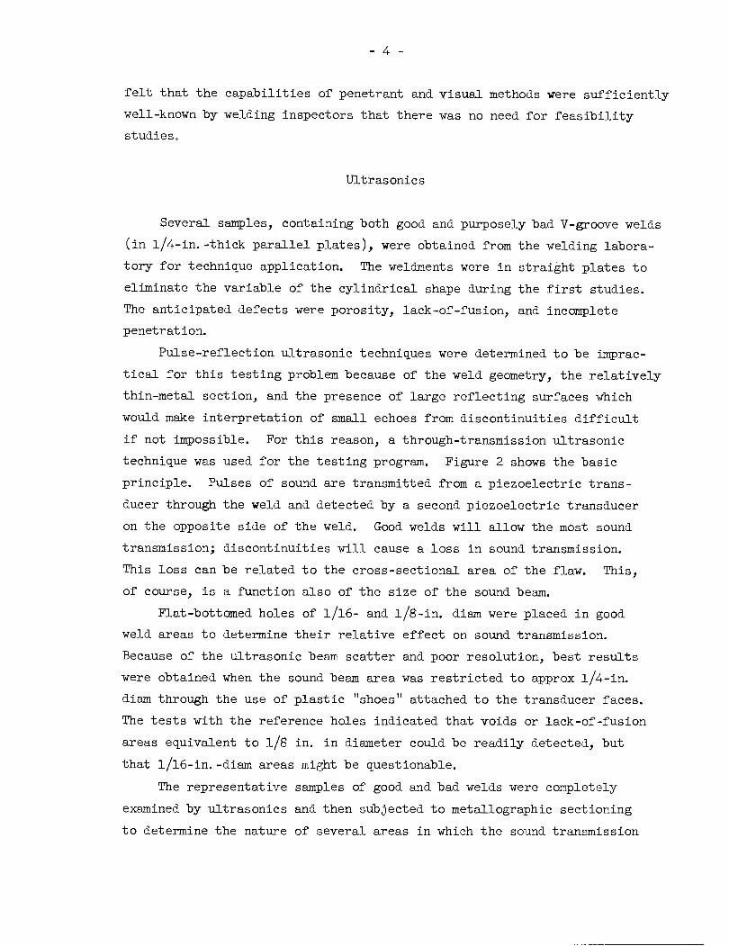
V-GROOVE WELDMENT
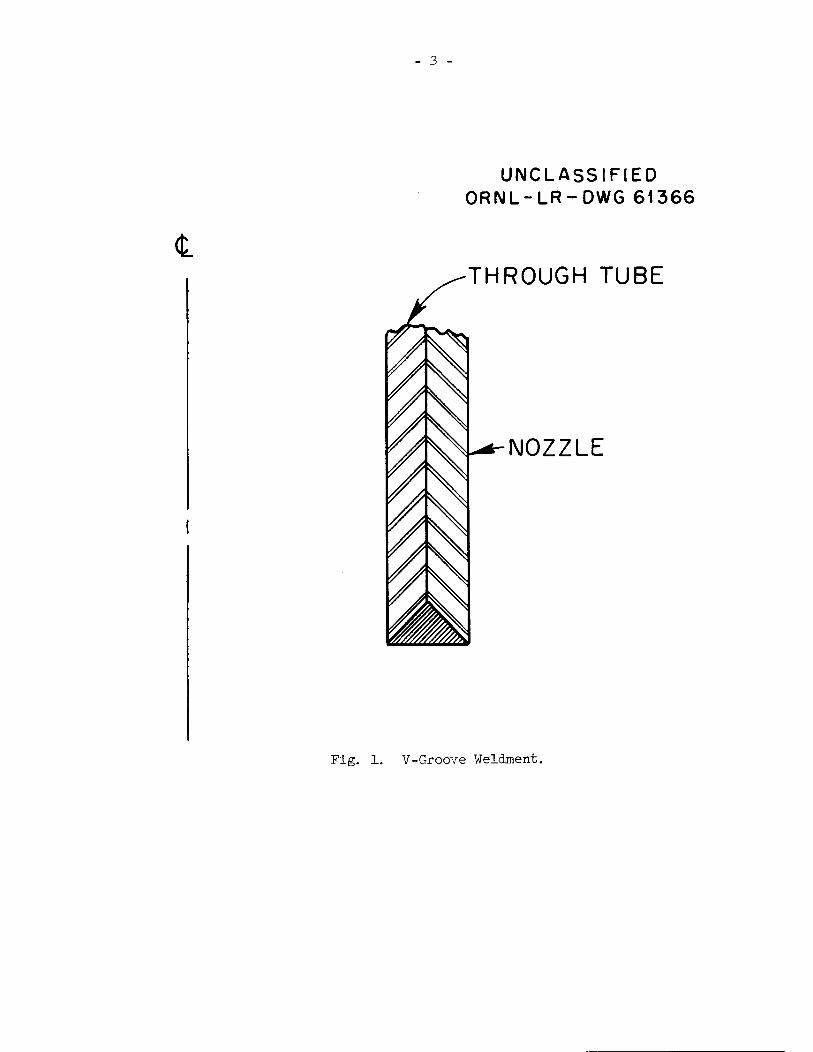
One of the proposed weld configurations for the through-tube weldment
was a V-groove similar to that shown in Fig. 1. The prime testing methods
which were considered for study were ultrasonics and radiography. It was
"""E. Storto, "Design of Experimental Gas-Cooled In-Pile Loops, "Symposium on Gas-Cooled Reactors, Franklin Institute Monograph No. 7,May 1960.
2F. H. Neill, GCR Quar. Prog. Rep. March 31, 1961, 0RNL-3102,pp 242-^7.
OAKRIDGE NATIONAL LABORATORY LIBRARIES
3 445b 0546755 1
<L
3 -
UNCLASSIFIED
ORNL-LR-DWG 61366
THROUGH TUBE
NOZZLE
Fig. 1. V-Groove Weldment.
- 4 -
felt that the capabilities of penetrant and visual methods were sufficiently
well-known by welding inspectors that there was no need for feasibility
studies.
Ultrasonics
Several samples, containing both good and purposely bad V-groove welds
(in l/4-in.-thick parallel plates), were obtained from the welding labora
tory for technique application. The weldments were in straight plates to
eliminate the variable of the cylindrical shape during the first studies.
The anticipated defects were porosity, lack-of-fusion, and incomplete
penetration.
Pulse-reflection ultrasonic techniques were determined to be imprac
tical for this testing problem because of the weld geometry, the relatively
thin-metal section, and the presence of large reflecting surfaces which
would make interpretation of small echoes from discontinuities difficult
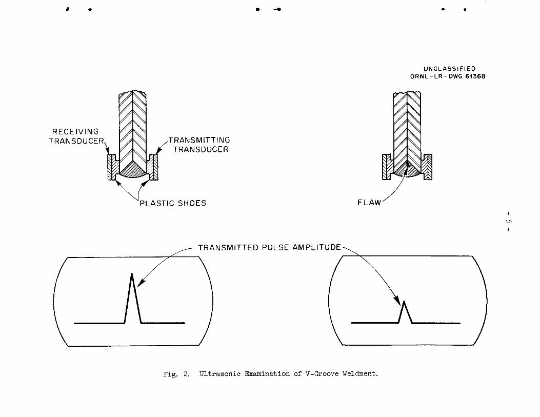
if not impossible. For this reason, a through-transmission ultrasonic
technique was used for the testing program. Figure 2 shows the basic
principle. Pulses of sound are transmitted from a piezoelectric trans
ducer through the weld and detected by a second piezoelectric transducer
on the opposite side of the weld. Good welds will allow the most sound
transmission; discontinuities will cause a loss in sound transmission.
This loss can be related to the cross-sectional area of the flaw. This,
of course, is a function also of the size of the sound beam.
Flat-bottomed holes of l/l6- and l/8-in. diam were placed in good
weld areas to determine their relative effect on sound transmission.
Because of the ultrasonic beam scatter and poor resolution, best results
were obtained when the sound beam area was restricted to approx l/4-in.
diam through the use of plastic "shoes" attached to the transducer faces.
The tests with the reference holes indicated that voids or lack-of-fusion
areas equivalent to l/8 in. in diameter could be readily detected, but
that l/l6-in. -diam areas might be questionable.
The representative samples of good and bad welds were completely
examined by ultrasonics and then subjected to metallographic sectioning
to determine the nature of several areas in which the sound transmission
RECEIVING
TRANSDUCER TRANSMITTING
TRANSDUCER
PLASTIC SHOES
TRANSMITTED PULSE AMPLITUDE
FLAW
Fig. 2. Ultrasonic Examination of V-Groove Weldment.
UNCLASSIFIED
ORNL-LR-DWG 61368
i
- 6
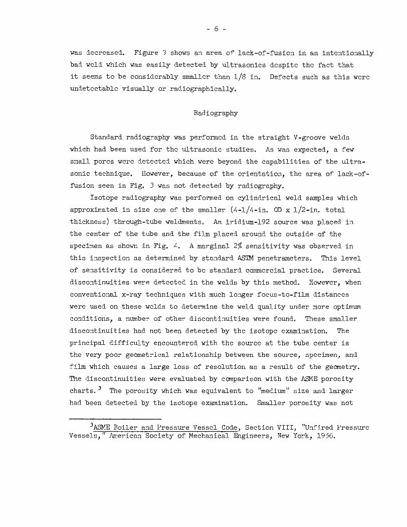
was decreased. Figure 3 shows an area of lack-of-fusion in an intentionally
bad weld which was easily detected by ultrasonics despite the fact that
it seems to be considerably smaller than l/8 in. Defects such as this were
undetectable visually or radiographically.
Radiography
Standard radiography was performed in the straight V-groove welds
which had been used for the ultrasonic studies. As was expected, a few
small pores were detected which were beyond the capabilities of the ultra
sonic technique. However, because of the orientation, the area of lack-of-
fusion seen in Fig. 3 was not detected by radiography.
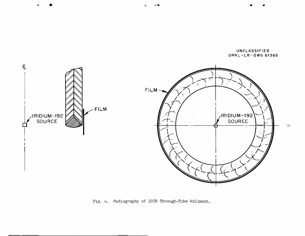
Isotope radiography was performed on cylindrical weld samples which
approximated in size one of the smaller (4-l/4-in. OD x l/2-in. total
thickness) through-tube weldments. An iridium-192 source was placed in
the center of the tube and the film placed around the outside of the
specimen as shown in Fig. 4. A marginal 2% sensitivity was observed in
this inspection as determined by standard ASTM penetrameters. This level
of sensitivity is considered to be standard commercial practice. Several
discontinuities were detected in the welds by this method. However, when
conventional x-ray techniques with much longer focus-to-film distances
were used on these welds to determine the weld quality under more optimum
conditions, a number of other discontinuities were found. These smaller
discontinuities had not been detected by the isotope examination. The
principal difficulty encountered with the source at the tube center is
the very poor geometrical relationship between the source, specimen, and
film which causes a large loss of resolution as a result of the geometry.
The discontinuities were evaluated by comparison with the ASME porosity
charts.3 The porosity which was equivalent to "medium" size and larger
had been detected by the isotope examination. Smaller porosity was not
ASME Boiler and Pressure Vessel Code, Section VIII, "Unfired PressureVessels," American Society of Mechanical Engineers, New York, 1956.
•
•
• .-
Unclassified
Y-42758
t
Fig. 3- Lack-of-Fusion in V-Groove Weldment.Etchant: Glyceria regia. 50X.
kRIDIUM-192
SOURCE
ZS
FILM
FILM
Fig. 4. Radiography of EGCR Through-Tube Weldment.
UNCLASSIFIED
ORNL-LR-DWG 61365
oa
detectable by the isotope technique but was discovered by x-ray examination.
The detection of small porosity should be slightly improved for the largerdiameter weldments.
Conclusions
Inspection of a V-groove weldment should include both through-
transmission ultrasonics and radiography. The isotope radiographic
technique can detect much smaller discrete gas and slag inclusions than
ultrasonics but would be relatively insensitive to lack-of-fusion. An
ultrasonic technique, on the other hand, would be a useful tool for the
detection of lack-of-fusion.
Liquid penetrant and visual examinations in accordance with standard
procedures would prove very valuable for the detection of surface-
connected porosity, cracks, and lack-of-fusion, any of which could be
undetected by the other methods. However, if the weld temperature is
above 125°F during inspection, further work may be necessary to demon
strate or develop penetrant techniques for use at higher temperatures.
FILLET WELDMENTS
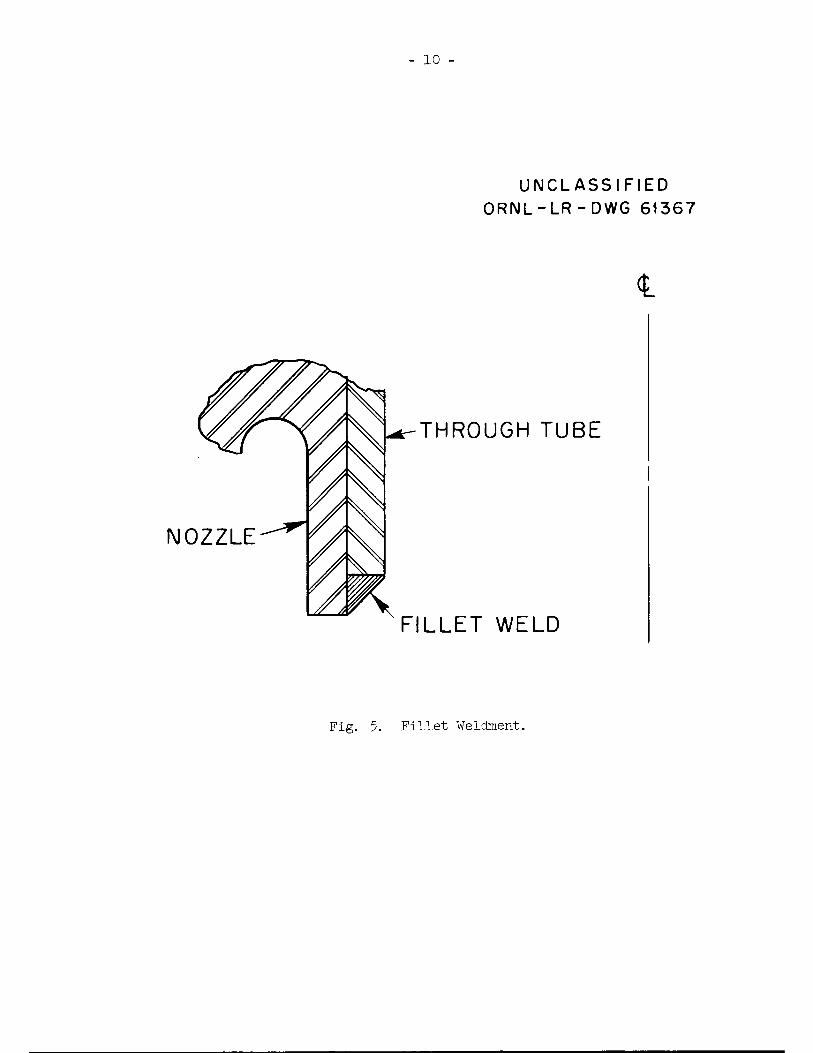
Because of a decision to use the fillet-weld configuration, such as
shown in Fig. 5, for the EGCR through-tube weldments, later stages of the
program were devoted exclusively to this weld shape.
Ultrasonics
The pulse-reflection ultrasonic technique was considered impractical,
at this time, for the evaluation of the fillet weldment for the same reasons
as were enumerated for the V-groove weldment. These included the relatively
thin sections and the presence of large reflecting surfaces which would
make interpretation of small echoes difficult. The lack of parallel sur
faces around the weld area precluded reasonable techniques for through-
transmission ultrasonics. Therefore, since the ultrasonic method did not
seem to be feasible, the major emphasis was placed on the radiographic
procedure.
NOZZLE
10
UNCLASSIFIED
ORNL-LR-DWG 61367
<L
THROUGH TUBE
FILLET WELD
Fig. 5. Fillet Weldment.
11
Radiography
Isotope radiography with the iridium-192 source on the tubular axis
was performed on sample fillet weldments. The geometrical considerations
were essentially the same as had been noted in Fig. 4 and in the dis
cussion on radiography of the V-groove weldment. A marginal 2% sensitivity
was attainable with fine porosity being undetectable.
Because of the configuration of this weld, the thickness penetrated
by the radiation will vary across the width of the weld from a single lip
thickness to the combined double thickness of both the through-tube and
the vessel nozzle. For the best sensitivity for the thickness range of
the weld, two-film techniques should be used to provide optimum film
density for each of the thickness limits. This can be accomplished by
the use of an appropriate filter in the film holder to control the relative
exposure on each of the films or by varying the developing time during the
film processing.
Conclusions
Inspection of a fillet weldment by the ultrasonic method does not
seem to be practical at the present time. Attainment of a useful ultra
sonic technique will require considerable development effort with no
assurance of success or that the evolved technique will be amenable to
the restriction on accessibility or the requirement for remote operation.
The radiographic technique can be used to detect lack-of-penetration and
"medium" porosity (as defined by the porosity charts of the ASME Boiler
and Pressure Vessel Code). Lack-of-fusion would not be detected except
in those instances in which it connected to the outer surface for obser
vation by penetrant or visual techniques. The capabilities for visual
and penetrant inspections would be similar to those for the V-groove
weldments.
- 12 -
IRRADIATION BACKGROUND
Simulation
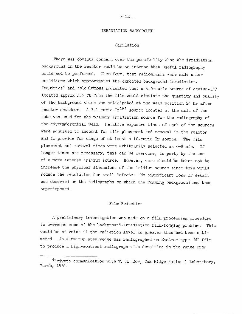
There was obvious concern over the possibility that the irradiation
background in the reactor would be so intense that useful radiography
could not be performed. Therefore, test radiographs were made under
conditions which approximated the expected background irradiation.
Inquiries4 and calculations indicated that a 4. 5-curie source of cesium-137
located approx 3.5 ft from the film would simulate the quantity and quality
of the background which was anticipated at the weld position 24 hr after
reactor shutdown. A 3.1-curie Ir192 source located at the axis of the
tube was used for the primary irradiation source for the radiography of
the circumferential weld. Relative exposure times of each of the sources
were adjusted to account for film placement and removal in the reactor
and to provide for usage of at least a 10-curie Ir source. The film
placement and removal times were arbitrarily selected as 6-8 min. If
longer times are necessary, this can be overcome, in part, by the use
of a more intense iridium source. However, care should be taken not to
increase the physical dimensions of the iridium source since this would
reduce the resolution for small defects. No significant loss of detail
was observed on the radiographs on which the fogging background had been
superimposed.
Film Reduction
A preliminary investigation was made on a film processing procedure
to overcome some of the background-irradiation film-fogging problem. This
would be of value if the radiation level is greater than had been esti
mated. An aluminum step wedge was radiographed on Eastman type "M" film
to produce a high-contrast radiograph with densities in the range from
^Private communication with T. H. Row, Oak Ridge National Laboratory,March, 1961.
13
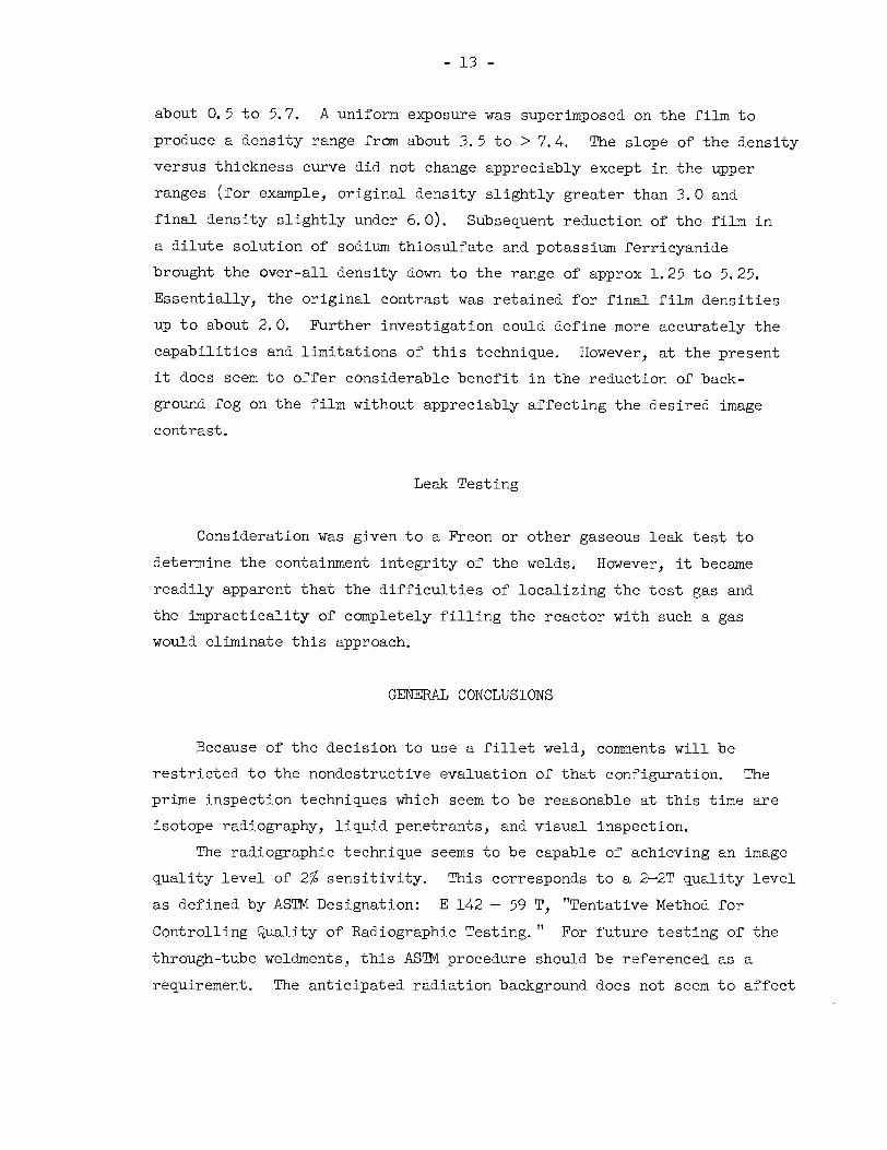
about 0. 5 to 5. 7. A uniform exposure was superimposed on the film to
produce a density range from about 3. 5 to > 7.4. The slope of the density
versus thickness curve did not change appreciably except in the upper
ranges (for example, original density slightly greater than 3. 0 and
final density slightly under 6.0). Subsequent reduction of the film in
a dilute solution of sodium thiosulfate and potassium ferricyanide
brought the over-all density down to the range of approx 1. 25 to 5. 25.
Essentially, the original contrast was retained for final film densities
up to about 2. 0. Further investigation could define more accurately the
capabilities and limitations of this technique. However, at the present
it does seem to offer considerable benefit in the reduction of back
ground fog on the film without appreciably affecting the desired image
contrast.
Leak Testing
Consideration was given to a Freon or other gaseous leak test to
determine the containment integrity of the welds. However, it became
readily apparent that the difficulties of localizing the test gas and
the impracticality of completely filling the reactor with such a gas
would eliminate this approach.
GENERAL CONCLUSIONS
Because of the decision to use a fillet weld, comments will be
restricted to the nondestructive evaluation of that configuration. The
prime inspection techniques which seem to be reasonable at this time are
isotope radiography, liquid penetrants, and visual inspection.
The radiographic technique seems to be capable of achieving an image
quality level of 2% sensitivity. This corresponds to a 2—2T quality level
as defined by ASTM Designation: E 142 - 59 T, "Tentative Method for
Controlling Quality of Radiographic Testing." For future testing of the
through-tube weldments, this ASTM procedure should be referenced as a
requirement. The anticipated radiation background does not seem to affect
14
adversely the radiographic quality. However, if necessary, the effect ofthe background can be minimized by the use of a stronger iridium-192
source, auxiliary shielding around the film, more rapid placement and
removal of the film, and the use of film-reducing techniques on the final
processed film. Of course, a major problem for the inspection will be
the remote placement of both radiation source and film into the proper
position. There are a number of manufacturers of radiographic equipment
who market devices for the remote placement of radioisotopes. Perhapssuch an item could be modified to accomplish the desired function. The
principal benefit from the radiographic procedure will be the detection
of porosity, slag inclusions, and lack of penetration.
Liquid penetrant examinations can be performed on welds of this
type in accordance with ASTM or ORNL specifications. The major problem
for this case will be the necessity for remote mechanical features to
perform the various steps of penetrant application, penetrant removal,developer application, and visual examination of the final results. It
will probably be necessary to provide capabilities for light grinding
or polishing on the weld for evaluation of penetrant indications. Of
course, the provision for viewing penetrant results which will include
both illumination and optical features will be useful for visual inspec
tion, which in itself is a very valuable tool. The penetrant and visual
examination will be of prime benefit for the detection of cracks and
lack-of-fusion which extend to the inspection surface.
It is felt that proper utilization of these test methods will result
in a reasonable inspection for the detection of gas porosity, slag in
clusions, lack of penetration, and surface cracking. Lack-of-fusion which
does not connect to the outer surface will be undetectable with current
techniques.
A serious problem for the accomplishment of each of these inspections
is that of development of the mechanical fixtures to perform the necessary
remote operations. It is felt that each can be accomplished. Consideration
should be given to the expense of achieving such an inspection as comparedto the benefits to be obtained.
- 15 -
DISTRIBUTION
1-2. Central Research Library3. Document Reference Section
4-8. Laboratory Records9. Laboratory Records, RC
10-24. Division of Technical Information Extension
25. Research and Development Division, ORO26. G. M. Adamson, Jr.27. M. Bender
28. W. B. Cottrell
29. J. H. Coobs
30. K. V. Cook
31. J. E. Cunningham32. D. A. Douglas, Jr.
33-62. W. F. Ferguson63. J. H Frye, Jr.64. R. M. Fuller