34
FES FLIGHT MANUAL Version 1.16 LZ Design d.o.o., ▪ Brod 3D, 1370 Logatec, Slovenia ▪ tel +386 59 948 898 [email protected] ▪ www.front-electric-sustainer.com

FES FLIGHT MANUAL Version 1.16
LZ Design d.o.o., ▪ Brod 3D, 1370 Logatec, Slovenia ▪ tel +386 59 948 898 [email protected] ▪ www.front-electric-sustainer.com

FES Flight Manual Version 1.16 October 2017
Page 2 of 33
Table of Content
1. General .................................................................................................................... 5 1.1 Introduction ...................................................................................................... 5 1.2 Certification basis .............................................................................................. 5 1.3 Warnings, cautions and notes ............................................................................ 5 1.4 Descriptive data ................................................................................................ 5 1.5 Three-view drawing ........................................................................................... 6 1.6 Abbreviations .................................................................................................... 7 1.7 Unit conversions................................................................................................ 7
2. Limitations ............................................................................................................... 8 2.1 Introduction ...................................................................................................... 8 2.2 Airspeed ........................................................................................................... 8 2.3 Airspeed indicator markings ............................................................................... 8 2.4 Power-plant ...................................................................................................... 8
2.4.1 Motor .......................................................................................................... 9 2.4.2 Propeller ..................................................................................................... 9 2.4.3 Battery packs .............................................................................................. 9
2.5 Power-plant instrument markings ....................................................................... 9 2.6 Weight ........................................................................................................... 10 2.7 Centre of gravity ............................................................................................. 10 2.8 Approved manoeuvres ..................................................................................... 10 2.9 Manoeuvring load factors................................................................................. 10 2.10 Flight crew ................................................................................................... 10 2.11 Kinds of operation ........................................................................................ 10 2.12 Minimum equipment ..................................................................................... 10 2.13 Aerotow and winch- and autotow-launching .................................................. 11 2.14 Other limitations ........................................................................................... 11 2.15 Limitations placards ...................................................................................... 11
3. Emergency procedures ........................................................................................... 12 3.1 Introduction .................................................................................................... 12 3.2 Canopy jettison ............................................................................................... 12 3.3 Bailing out ...................................................................................................... 12
3.3.1 Ballistic parachute ...................................................................................... 12 3.4 Stall recovery .................................................................................................. 12 3.5 Spin recovery .................................................................................................. 12 3.6 Spiral dive recovery ......................................................................................... 12 3.7 Motor failure ................................................................................................... 12
3.7.1 Motor fail to start....................................................................................... 12 3.7.2 Power loss during flight .............................................................................. 13
3.8 Fire ................................................................................................................ 14 3.8.1 Fire on the ground ..................................................................................... 14 3.8.2 Fire during flight ........................................................................................ 14
3.9 Other emergencies .......................................................................................... 14 3.9.1 Loss of 12V electrical power in flight ........................................................... 14
4. Normal procedures ................................................................................................. 15 4.1 Introduction .................................................................................................... 15 4.2 Rigging and de-rigging, charging, battery pack installation ................................ 15
4.2.1 Rigging and de-rigging ............................................................................... 15 4.2.3 Installing the batteries ............................................................................... 16
4.3 Daily inspection ............................................................................................... 16

FES Flight Manual Version 1.16 October 2017
Page 3 of 33
4.4 Pre-flight inspection ........................................................................................ 16
4.4.1 Preflight test run .......................................................................................... 17 4.5 Normal procedures and recommended speeds .................................................. 18
4.5.1 Aero tow launch ........................................................................................ 18 4.5.1 Aero tow launch ........................................................................................ 18 4.5.2 Winch launch ........................................................................................... 18 4.5.3 Auto tow launch ........................................................................................ 18 4.5.4 Taxiing procedures .................................................................................... 18 4.5.5 Self-launch and climb ................................................................................. 19 4.5.6 Free flight ................................................................................................. 19 4.5.7 Low speed flight and stalling behavior ........................................................ 19 4.5.8 Cruise and climbing with running motor ...................................................... 20
4.5.8.1 Propeller stop with electronic braking ....................................................... 20 4.5.8.2 Propeller positioning ............................................................................... 21
4.5.9 Approach .................................................................................................. 21 4.5.10 Landing..................................................................................................... 22
4.5.10.1 After Landing ........................................................................................ 22 4.5.10.2 Removing the batteries ......................................................................... 22
4.5.11 Flight with water ballast ............................................................................. 23 4.5.12 High altitude flight ..................................................................................... 23 4.5.13 Flight in rain .............................................................................................. 23 4.5.14 Aerobatics ................................................................................................. 23
5. Performance .......................................................................................................... 24 5.1 Introduction .................................................................................................... 24 5.2 Approved data ................................................................................................ 24
5.2.1 Airspeed indicator system calibration .......................................................... 24 5.2.2 Stall speeds ............................................................................................... 24 5.2.3 Take-off performance ................................................................................ 24 5.2.4 Additional information ................................................................................ 25
5.3 Non-approved further information .................................................................... 25 5.3.1 Demonstrated crosswind performance ........................................................ 25 5.3.2 Glide performance ..................................................................................... 25 5.3.3 Flight polar ................................................................................................ 26 5.3.4 Powered flight performance ....................................................................... 26
5.3.4.1 Rate of climb .......................................................................................... 26 5.3.4.2 Cruising flight ......................................................................................... 27 5.3.4.3 Maximum operational altitude .................................................................. 27
5.3.5 Noise data ................................................................................................. 27 5.3.6 Electromagnetic interferences ..................................................................... 27
6. Weight and balance ................................................................................................ 28 6.1 Introduction .................................................................................................... 28 6.2 Weight and Balance Record and permitted payload-range ................................. 28 6.3 Weight of all non-lifting parts ........................................................................... 28 6.4 Maximum weight ............................................................................................. 28
7. General sailplane and systems description ................................................................ 29 7.1 Introduction .................................................................................................... 29 7.2 Cockpit controls .............................................................................................. 29 7.3 Instrument panel ............................................................................................ 29 7.4 Landing gear system ....................................................................................... 29 7.5 Seats and safety harness ................................................................................. 29 7.6 Pitot and static system .................................................................................... 29
FES Flight Manual Version 1.16 October 2017
Page 4 of 33
7.7 Air brakes system ............................................................................................ 29 7.8 Baggage Compartment .................................................................................... 30 7.9 Water ballast system ....................................................................................... 30 7.10 Powerplant................................................................................................... 30 7.11 Battery packs ............................................................................................... 30 7.12 Electrical system ........................................................................................... 30 7.13 Miscellaneous equipment .............................................................................. 30
8. Sailplane handling, care and maintenance ................................................................ 31 8.1 Introduction .................................................................................................... 31 8.2 FES inspection periods ..................................................................................... 31 8.3 Sailplane alterations or repairs ......................................................................... 31 8.4 Ground handling / road transport ..................................................................... 31 8.5 Sailplane trailer ............................................................................................... 33 8.6 Cleaning and care ........................................................................................... 33
9. Supplements .......................................................................................................... 33 10. Revision history .................................................................................................... 33
FES Flight Manual Version 1.16 October 2017
Page 5 of 33
1. General
1.1 Introduction.
The FES flight manual has been prepared to provide: 1. Pilots with information for the safe and efficient operation of the sailplanes
equipped with Front Electric Sustainer/Self-launcher system. 2. Sailplane manufacturer of specific type of sailplane equipped with FES, with all the
information necessary to prepare flight manual of the sailplane after FES installation. Chapters of this manual are written as it is requested by CS-22 requirements.
1.2 Certification basis
This type of powered sailplane has been designed in accordance with CS 22 Certification Specifications for Sailplanes and Powered Sailplanes, and in accordance with Special Conditions for electric powered sailplanes. 1.3 Warnings, cautions and notes
The following definitions apply to warnings, cautions and notes used in the flight
manual.
Warning: Means that the non-observation of the corresponding procedure leads to an immediate or important degradation of the flight safety.
Caution: Means that the non-observation of the corresponding procedure leads to a minor or to a more or less long-term degradation of the flight safety.
Note: Draws the attention on any special item not directly related to safety by which is important or unusual.
1.4 Descriptive data
Sailplane is equipped with a high-tech powerful FES front electric propulsion system
developed for high performance powered sailplanes. Main parts of the FES system are:
• Brushless electric motor • Controller for motor • Foldable propeller • FES GEN 2 Battery packs, with internal BMS (Battery Management System) • Charger (600W, 1200W or 2000W) • FCU (FES control unit) instrument • LXUI box with Shunt (for current and voltage measurements) • FCC box (FES connecting circuit) • Power switch • DC/DC converter (converts high voltage to 12V)
FES Flight Manual Version 1.16 October 2017
Page 6 of 33
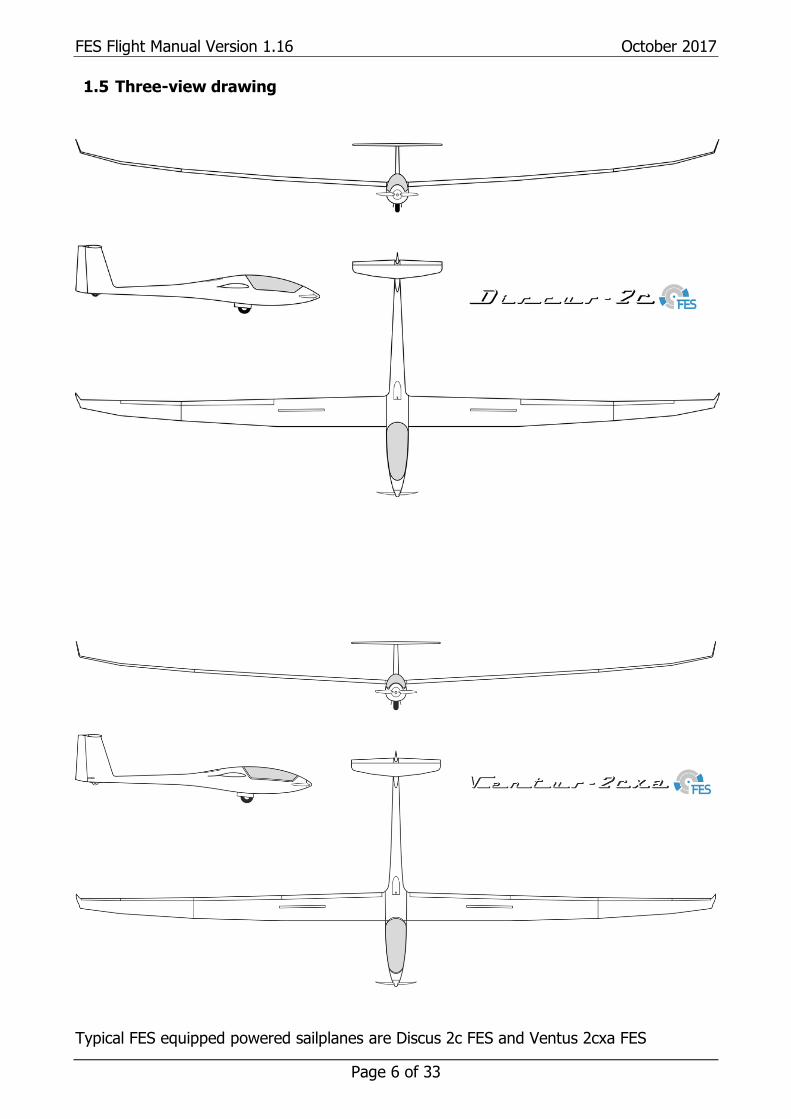
1.5 Three-view drawing
Typical FES equipped powered sailplanes are Discus 2c FES and Ventus 2cxa FES
FES Flight Manual Version 1.16 October 2017
Page 7 of 33
1.6 Abbreviations CAS - calibrated airspeed means indicated airspeed of a sailplane, corrected for
position (due to position of pressure ports on sailplane) and instrument error. Calibrated airspeed is equal to true airspeed in standard atmosphere at sea level
C.G. - centre of gravity daN FES FCU
- decanewton - Front Electric Sustainer/Self-launcher - FES Control Unit
H - hour IAS - indicated airspeed means the speed of a sailplane as shown on its pitot – static
aircraft indicator and is uncorrected for the system error M - meter Kg - kilogram Km - kilometre S - second Ltr - liter
1.7 Unit conversions
1 bar = 14,5 pounds per square inch (psi); 1 decanewton (daN) = 2,25 pounds force; 1 kilogram (kg) = 2,2 pounds (lbs); 1 meter (m) = 39,4 inches (in.) = 3,28 feet (ft.); 1 millimeter (mm) = 0,0394 inches (in.); 1 liter = 0,2642 U.S. gal; 1 square meter (m2) = 10,764 sq.ft; 1 kg/m2 = 0,204 lbs/sq.ft; 1 m/s = 1,944 knots (kts); 1 km/h = 0,5396 kts; 1 kW = 1,34 HP.
FES Flight Manual Version 1.16 October 2017
Page 8 of 33
2. Limitations
2.1 Introduction
This chapter includes operation limitations, instrument markings and placards, necessary or safe operation of the sailplane equipped with Front Electric Sustainer system.
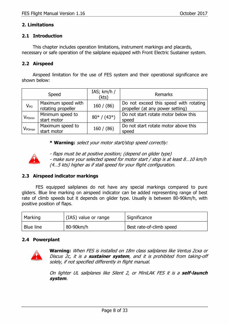
2.2 Airspeed
Airspeed limitation for the use of FES system and their operational significance are shown below:
Speed IAS; km/h /
(kts) Remarks
VPO Maximum speed with rotating propeller
160 / (86) Do not exceed this speed with rotating propeller (at any power setting)
VPOmin Minimum speed to start motor
80* / (43*) Do not start rotate motor below this speed
VPOmax Maximum speed to start motor
160 / (86) Do not start rotate motor above this speed
* Warning: select your motor start/stop speed correctly:
- flaps must be at positive position; (depend on glider type) - make sure your selected speed for motor start / stop is at least 8…10 km/h (4…5 kts) higher as if stall speed for your flight configuration.
2.3 Airspeed indicator markings FES equipped sailplanes do not have any special markings compared to pure gliders. Blue line marking on airspeed indicator can be added representing range of best rate of climb speeds but it depends on glider type. Usually is between 80-90km/h, with positive position of flaps. Marking
(IAS) value or range
Significance
Blue line
80-90km/h
Best rate-of-climb speed
2.4 Powerplant
Warning: When FES is installed on 18m class sailplanes like Ventus 2cxa or Discus 2c, it is a sustainer system, and it is prohibited from taking-off solely, if not specified differently in flight manual.
On lighter UL sailplanes like Silent 2, or MiniLAK FES it is a self-launch system.

FES Flight Manual Version 1.16 October 2017
Page 9 of 33
2.4.1 Motor Motor manufacturer: LZ design d.o.o.; Motor model: FES-xxx-Myyy; xxx - represent version of motor for specific glider type yyy - represent motor length More detailed data about motor which is used on specific type of FES powered sailplane are described in separate FES motor manual! 2.4.2 Propeller Manufacturer: LZ design d.o.o. Model: FES-xxx-Pv-yyy; xxx - represents type of sailplane for which the propeller is designed v - represents version of propeller for specific glider type yyy - represents propeller diameter in mm 2.4.3 Battery packs
FES needs two Battery packs wired in serial. Each Battery pack has 14 cells, so altogether there is 28 cells.
Maximum allowed total voltage of both Battery packs 118 V
Minimum allowed total allowed voltage of both Battery packs 90 V
Nominal capacity of each cell 40 Ah
Energy storage capacity 4,2 kWh
Maximum voltage per cell 4,16 V
Middle voltage 3,7 V
Minimum voltage of each cell 3,2 V
More detailed data about battery packs which is used on specific type of FES
powered sailplane are described in separate FES Battery pack manual! 2.5 Power-plant instrument markings FES power plant has a FCU instrument with high resolution sunlight visible colour display. More detailed data about FCU and its operation can be found in separate FES FCU INSTRUMENT manual!
FES Flight Manual Version 1.16 October 2017
Page 10 of 33
2.6 Weight FES system can be installed only on such type of sailplanes which have enough margin in maximum weight of non-lifting parts. Total weight of all FES components including reinforcement ribs for battery compartment box is about 50kg. However, 12V batteries are not required anymore (except one which is required as buffer battery-usually tail battery remains), so they can be removed from a glider to save some weight (2 pcs of standard 12V-7Ah Pb battery have total weight about 5kg). Exact FES weight depends on type of sailplane, and installed FES components. 2.7 Centre of gravity Components of FES system are positioned so that after FES installation C.G. position remains as much as possible on the same position as with pure sailplane. After installation sailplane C.G. must be checked and corrected if necessary.
Warning: Flying with removed motor is not allowed, if not specified differently for certain type. Warning: Flying without battery packs is not allowed, if not specified differently for certain type.
2.8 Approved maneuvers Aerobatic maneuvers with FES equipped sailplanes are not permitted, unless it is specified differently for a certain glider type. 2.9 Maneuvering load factors Depends on type of sailplane. 2.10 Flight crew Depends on type of sailplane. 2.11 Kinds of operation Flights must be conducted under Day / VFR conditions.
Warning: Flying under power in heavy rain is not allowed! Make sure that cover of battery compartment is sealed with plastic tape. Warning: For sailplanes equipped with sustainer system it is prohibited from taking off solely by the means of its own power.
2.12 Minimum equipment As specified in flight manual of pure sailplane.
FES Flight Manual Version 1.16 October 2017
Page 11 of 33
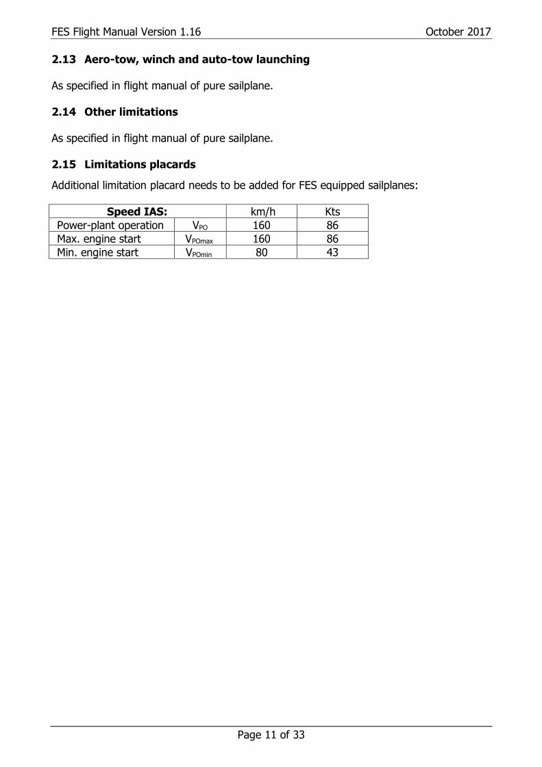
2.13 Aero-tow, winch and auto-tow launching As specified in flight manual of pure sailplane. 2.14 Other limitations As specified in flight manual of pure sailplane. 2.15 Limitations placards Additional limitation placard needs to be added for FES equipped sailplanes:
Speed IAS: km/h Kts
Power-plant operation VPO 160 86
Max. engine start VPOmax 160 86
Min. engine start VPOmin 80 43
FES Flight Manual Version 1.16 October 2017
Page 12 of 33
3. Emergency procedures 3.1 Introduction
According flight manual of pure sailplane. 3.2 Canopy jettison
Warning: Before canopy jettison, stop motor and switch OFF power switch, if there is still enough time to do that.
3.3 Bailing out
Warning: Before you bail out, stop motor and switch OFF power switch, if there is still enough time to do that.
3.3.1 Ballistic parachute
If sailplane is equipped with a ballistic parachute, a special switch is installed which stops motor automatically in case of activation!
3.4 Stall recovery As specified in flight manual of pure sailplane. 3.5 Spin recovery
As specified in flight manual of pure sailplane. 3.6 Spiral dive recovery
As specified in flight manual of pure sailplane. 3.7 Motor failure 3.7.1 Motor fail to start
If the motor fail to start, continue flying as a pure glider.
Note: Check if you maybe forgot to switch ON the Power switch. Reminding message (on the FCU)“Check power switch” should appear if there was high enough throttle set.
FES Flight Manual Version 1.16 October 2017
Page 13 of 33
3.7.2 Power loss during flight
If power is lost during flight, propeller will still rotate as windmill. Push the control
stick forward gently, to sustain desired airspeed! Than you can do next actions:
1. Check first if you maybe unintentionally switched OFF power switch! Warning: This can happen during retraction of landing gear on some glider types (LAK17A&B FES) where “Power switch” (toggle switch with red protection cover) is located on the same side of cockpit like landing gear retraction handle.
If this happened, just switch Power switch ON again and adjust throttle knob. Note: On earlier software versions (below v2.13), it was necessary to manually reduce throttle bar to zero, otherwise motor did not start due to safety. When throttle was reduced to zero than motor started normally. On new versions (from FCU v2.13) throttle bar goes to zero automatically!
2. If Power switch was not unintentionally switched OFF, as described in 1st point, proceed with next actions:
• switch OFF “Power switch” and then also FCU. • turn ON FCU and check it for any strange behaviour. • If everything is Ok switch on Power switch, and try to start motor again.
If motor starts and there is any strange behaviour under power:
• stop the propeller from the wind milling phase with the electronic brake. • After propeller is stopped, switch OFF Power switch and FCU as usually.
In case that you are not able to stop propeller with electronic brake, you will need to land with the propeller in wind-milling phase. Note that with reducing airspeed down to minimal speed is not possible to stop propeller from wind-milling. In such situation try to land carefully on both landing wheels simultaneously, to avoid possible damage of the propeller.
Note: If there is a grass runway in good condition available it is probably better to use it than concrete runway. If there is a grass runway with some holes than it is probably better to use a concrete runway if is available.
Warning: Try to avoid landing into high grass or similar.
Note: L/D of sailplane with propeller in wind milling phase is only a little degraded, so you might have enough time to choose a suitable landing place if you have enough altitude.
Please study FES FCU Instrument manual for detailed behaviour and necessary actions after appearance of certain messages or LED lights.
FES Flight Manual Version 1.16 October 2017
Page 14 of 33
3.8 Fire
3.8.1 Fire on the ground
• switch OFF the “Power switch” • switch OFF all instruments, and master switch of instruments • get out of cockpit • extinguish fire
3.8.2 Fire during flight
In all FES equipped gliders must be installed independent fire warning system which warns a pilot via very bright red blinking LED light, installed on top middle area of instrument panel, in case when temperature in battery compartment reach more than 88°C.
In certain cases, pilot could recognize fire also by smell. Next actions are proposed:
• stop motor immediately • switch OFF the “Power switch” • open front ventilation if not already opened • open canopy side window • land as soon as possible (or bail out if appropriate) • extinguish fire after landing
3.9 Other emergencies 3.9.1 Loss of 12V electrical power in flight During soaring flight:
If electronic instruments (radio, flight computer, FCU etc) stop working, during soaring flight, then continue to fly as a pure sailplane. In such case you will not be able to start FES. However, in case that FCU still works, you can try to start motor if necessary. During powered flight:
If FCU stop working during powered flight, then also motor stops working. However, propeller would still rotate as windmill and it would not be possible to stop it. You will need to land with rotating propeller. In such case try to land on both landing gears simultaneously, to avoid damage of propeller.
If case that only some of the instruments would stop working during powered flight, but motor and FCU would still work fine, then you can continue to use motor.

FES Flight Manual Version 1.16 October 2017
Page 15 of 33
4. Normal procedures 4.1 Introduction
This chapter provides checklists and explanations of procedures for conducting normal operating procedures. Normal procedures associated with optional equipment can be found in Chapter 9. 4.2 Rigging and de-rigging, charging, battery pack installation
4.2.1 Rigging and de-rigging of sailplane
Same as described in manual of pure sailplane.
Warning: Make sure that connecting cable is not installed, between Battery packs (if they are fixed inside the fuselage)
4.2.2 Charging the batteries Valid for FES Self-launchers: For self-launching FES battery packs must be always recharged, so that maximum power for good climb rate is available. This is especially important for: -cold batteries, when voltage drop under high power load is bigger -short runways -high altitude runways -hot summer conditions Valid for FES Self-sustainers: Before each flying day, battery packs should be recharged, especially if motor was significantly used during previous flights, and long cross-country flight is planned; so that maximum energy will be available when needed.
Note: It is recommended to recharge Battery packs just a day or two before flight is planned. However, plan charging so that there will be enough time for properly completed charging process!
Detailed instructions about charging of Battery packs are described in separate FES Battery pack manual.
FES Flight Manual Version 1.16 October 2017
Page 16 of 33
4.2.3 Installing the batteries
Warning: Make sure that both battery packs are fully charged before installation into sailplane. Both battery packs must have approximately the same voltage level of each cell (close to 4.16 V per cell). There should be less than 1V difference, between total voltage levels of each battery pack!
1. Check batteries for any visual damage
Warning: Even small visually detectable damages imply that the affected battery is not airworthy.
2. Open battery compartment cover 3. Check: Power switch (Key) OFF 4. Check: Sailplane main switch (fuse) OFF
5. Insert first pack (terminals facing forward) and slide it back to rear position 6. Insert second pack (terminals are facing rearward) 7. Place pair of fixation plates in the middle of rear pack, above carrying strap and
tighten fixation knob 8. Secure forward battery in the same way
9. Lift power cables from side support 10. Plug in shorter cable, with 8mm pin in BLUE (or BLACK) housing, to minus marked
8mm socket of front battery pack 11. Plug in longer cable with 10mm pin in RED housing, to plus marked 10mm socket of
rear battery pack
12. Insert DATA cable connectors, to each battery pack DATA connector
Caution: Prior to insert DATA cable connector make sure that the orientation
is correct. Connector should be plugged in straight direction, otherwise pins
could be damaged.
13. Close battery compartment cover.
4.3 Daily inspection
Please keep in mind the importance of the inspection after rigging the glider and respectively each day prior to the first take off. As a minimum check the following items. If any problems are found they must be corrected before flight.
• Check the sailplane as required for each type according its Flight Manual. • Check the FES system visually especially propeller blades condition • Check function of fire warning flashlight by test button (must light up brightly,
about one time per second, if necessary exchange 9V battery)
4.4 Pre-flight inspection
• Check the sailplane itself as requested before a flight • Perform short preflight test run as described below
FES Flight Manual Version 1.16 October 2017
Page 17 of 33
4.4.1 Preflight test run
After battery packs were recharged, it is always required to perform short motor run, so that FCU instrument can recognize recharge and new charge level is stored to the FCU memory. Short motor run is also recommended before first flight in flying day.
1. Remove propeller covers and a tail dolly 2. Open battery compartment cover 3. Check: Power switch OFF 4. Switch ON, BMS on each battery pack, and wait until initial check is completed 5. Insert Connecting cable between the battery packs 6. Close battery compartment cover, and seal it with tape 7. Seat into the glider, and close canopy 8. Check that no one is around propeller zone, in front of glider or in line of propeller 9. Switch ON, FCU instrument 10. Switch ON, Power switch 11. Wait about 5 second, for FCU to show all battery bottles 12. Start motor but use only low power to check proper operation
Caution: In case that you would like to test, system at maximum power, somebody must hold a fuselage tube down, so that glider cannot lift tail, which could result in damaged propeller blades. Warning: Do not run the motor for longer time, on the ground, especially not at high power! When motor is stopped, also cooling is stopped, and so motor temperature can rise very quickly, which can lead to damaged motor!
13. Stop motor and check if automatic positioning is working fine 14. Switch OFF Power switch
FES Flight Manual Version 1.16 October 2017
Page 18 of 33
4.5 Normal procedures and recommended speeds
As described for a pure sailplane, but have in mind that with installed FES your glider has higher wing loading, so you have to adjust speeds accordingly.
4.5.1 Aero tow launch
Before take-off, always switch ON the FCU instrument. Double check that “Power switch” is OFF before somebody approach front area of the glider in order to attach tow rope to the hook. All the time during tow, “Power switch” should be OFF!
Warning: It is not allowed to start FES motor during aero tow!
4.5.2 Winch launch
Before take-off, always switch ON the FCU instrument. Double check that “Power switch” is OFF before somebody approach front area of the glider in order to attach towing cable to the hook. All the time during winch launch, “Power switch” should be OFF!
Warning: It is not allowed to start FES motor during winch launch! Towing rope must be always released before running FES motor.
4.5.3 Auto tow launch
Before take-off, always switch ON the FCU instrument. Double check that “Power switch” is OFF before somebody approach front area of the glider in order to attach towing rope to the hook. During tow, “Power switch” should be OFF!
Warning: It is not allowed to start FES motor during auto tow launch! Towing rope must be always released before running FES motor.
4.5.4 Taxiing procedures
Warning: Taxiing is not allowed when FES is installed as sustainer system!
Your sailplane needs to be factory equipped with steerable tail wheel, and small
wing tip wheels to be suitable for taxiing. Do not try to use tail dolly for taxiing! For taxiing, use only concrete or good grass runways with short grass. Do not try to
taxi if runway is with a holes, otherwise propeller blades can be damaged! To start moving, use a little bit more power, but then decrease it quickly, so that
you will not be taxiing too fast. Try not to use a wheel brake, or use it very carefully, to avoid damaging propeller!
FES Flight Manual Version 1.16 October 2017
Page 19 of 33
4.5.5 Self-launch and climb
Warning: Self-launch is not allowed when FES is installed as sustainer system!
Before a self-launch be always prepared, what actions you will do in case of motor
failure, during different stages of take-off. Take into account wind conditions, airfield altitude, length of runway, obstacles at the end of runway, outside temperature etc.
If runway is very short, with a lot of obstacles and without alternatives in case of motor failure, then simply do not fly there!
Caution: Always avoid performing take-off with tail wind!
Self-launch procedure:
1. Check that tail dolly and propeller covers are removed 2. Seat into the glider, fasten your seat belts and close the canopy 3. Check that airbrakes are closed, and trimmer set to proper position 4. Position flaps to proper position for take-off (depending on type of sailplane) 5. Check that motor ventilation is opened 6. Check that no one is around propeller zone, in front of sailplane or in line of
propeller (call “clear prop”) 7. Switch ON FCU instrument 8. Switch ON Power switch, and wait until all parameters become visible 9. Ask for take-off permission by radio, and wait for approval 10. Start motor with rotating throttle knob in clockwise direction to low RPM 11. Gently rotate throttle knob clockwise to maximum power 12. Accelerate, adjust flaps position and gently lift off at suitable speed 13. When safe altitude is reached, reduce power and continue with climbing 14. Retract landing gear
Caution: During Self-Launching, pay attention to any other traffic in the circuit – which may not be familiar with electric self-launching sailplanes (and may not expect your aircraft to launch unassisted)
4.5.6 Free flight
As described for a pure sailplane, but have in mind that with installed FES your glider has higher wing loading, so adjust speeds accordingly. FCU instrument should be always ON during soaring flight. 4.5.7 Low speed flight and stalling behaviour
As described for a pure sailplane, but have in mind that with FES, your glider has about 5kg/m2 higher wing loading, and as result of that minimum speed is higher.

FES Flight Manual Version 1.16 October 2017
Page 20 of 33
4.5.8 Cruise and climbing with running motor
FES can be used for long continuous cruise at low power settings, or climbing at higher power settings!
Caution: During motor operation, ventilation must be fully opened (depends on type of sailplane; usually ventilation lever must be pushed fully forward). Warning: I case that you forget to open ventilation; warning message “Check ventilation” will appear on the FCU screen. FCU monitors temperature rise gradient, and when gradient is more than usual with opened ventilation such message will appear!
Motor starting procedure during flight: 1. Check that all values on the FCU instrument are in normal range (FCU must be always switched ON during flight) 2. Turn ON Power Switch 3. Check if there is green LED ON (left lower LED), check Voltage level (If there is no green LED or red LED is blinking motor will not run). Read FES FCU instrument manual for detailed FCU description 4. Start motor with Throttle knob rotating in clockwise direction gently.
Use about 4kW of power for horizontal flight, and more for climbing. Maximum climb rate depends on glider type and it is affected by its weight, speed, flaps position etc.
Available maximum power is reducing slowly due to voltage drop, during discharging of battery packs. Maximum power can be used only until any of temperature values reach yellow warning. (motor and controller at 70 deg, battery packs at 45 deg)!
Note: You can reduce power in thermals, and use more power in sinking air
Do not use high current at lower voltages; this mean below 95V. Always try to fly as
much as possible on lower power settings where efficiency of complete system is the highest!
During soaring flight always keep the FCU turned ON. Switch OFF Power switch if motor is not running.
4.5.8.1 Propeller stop with electronic braking
To stop propeller with electronic braking, you need to rotate Throttle knob in counter-clockwise direction for 1 step, from zero throttle, so that throttle line on display starts blinking red!
Note: For successful stop the motor should reach about 1500 RPM, otherwise braking will not work, due to insufficient induced voltage (regeneration function of controller is used for propeller braking).
FES Flight Manual Version 1.16 October 2017
Page 21 of 33
In the air there is nearly always enough RPM. But if you want to test
electronic braking on the ground, make sure you set at least 1500 RPM, and then rotate throttle knob quickly in counter clockwise direction! 4.5.8.2 Propeller positioning 1. FES installations without automatic positioning: If propeller stops in such position that pilot can see one of the blades trough the canopy, just start motor again to about 1500 RPM and then stop it again. Repeat this procedure until blades are randomly positioned in suitable position! 2. FES installations with automatic positioning: If your FES system is equipped with automatic positioning of blades, the electronics will rotate them in horizontal position. After electronic braking stops motor, wait for 2-3 second, until RPM data shows zero RPM. After that automatic positioning will start! You can always stop automatic positioning by pressing throttle knob.
Note: Positioning will not work if Canopy message is active, or if throttle is set to zero power instead of braking!
In settings it is possible to adjust: -time between steps from 50ms to 1 sec
-power used for positioning at 115V and at 90V -number of steps after hall sensor for position is detected 4.5.9 Approach
As pure glider, but have in mind that with installed FES your glider has higher wing loading, so increase landing speed for 5 to 10km/h. Check that propeller blades are parked in horizontal position and “Power switch” is switched OFF.
FES Flight Manual Version 1.16 October 2017
Page 22 of 33
4.5.10 Landing
As pure glider, but have in mind that with installed FES your glider has higher wing loading, so increase landing speed for 5 to 10km/h. Land always with propeller blades in horizontal position, or propeller blades might be damaged during landing, or during opening of the canopy. 4.5.10.1 After Landing
Warning: After landing (or if you decided not to fly) it is mandatory to unplug “Connecting cable”, from the battery packs! At the same time, also both BMS switch on top of the battery packs, must be switched OFF. Caution: Make sure that “Power switch” is OFF before removing connecting cable;
Note: Only when connecting cable is unplugged, FES system is completely shut down. Otherwise there is still some current consumption, which could result in discharge of battery packs, below critical level of 90V, if connecting cable is left connected for a week or two. After such scenario, a new battery packs would be required.
If motor was used during flight, take out both batteries and recharge them
according charging instructions in FES Battery pack manual. 4.5.10.2 Removing the batteries 1. Check: Power switch OFF. 2. Check: Sailplane main switch (fuse) OFF
3. Open battery compartment cover. 4. Remove Connecting cable from terminals of battery packs. 5. Remove red and black power plugs from battery packs
6. Fix both power cables on right side of battery compartment wall
7. Remove DATA connectors from each battery packs
8. Fix DATA cable to side of battery compartment
9. Unscrew both battery pack fixation knobs
10. Take all fixation plates out. 11. Firmly grip the front battery by a carrier strap. 12. Lift the front battery out of the fuselage and put it on a safe place
13. Firmly grip the rear battery by the carrier strap and slide it forward along the bottom of the compartment
14. Lift the rear battery out of the fuselage and put it on a safe place
15. Close battery compartment cover
Caution: For transport and storage of the batteries always a transport box or something similar must be used which protects the batteries from mechanical damage. Make sure you put batteries on a dry and safe place. Please read FES Battery pack manual for more detailed instructions.
FES Flight Manual Version 1.16 October 2017
Page 23 of 33
4.5.11 Flight with water ballast
As described for a pure sailplane.
If you want to achieve maximum climb rate performance or range under power, then drop water ballast. 4.5.12 High altitude flight As described for a pure sailplane. Check also chapter 5.3.4.3 Maximum operational altitude. 4.5.13 Flight in rain
Always avoid flying through heavy rain and thunderstorms. It is recommended to close ventilation, to prevent entering water into the spinner. Before flight seal battery compartment with a glider tape, to prevent water entering.
Warning: Avoid flying close to lightning activity!
It is allowed to fly through light rain, with running motor if necessary. However, use only lower RPM settings, suitable for horizontal flight, to avoid damaging propeller blades. Stop motor if rain becomes stronger.
4.5.14 Aerobatics
Aerobatic maneuvers are in general not allowed with a FES equipped sailplanes, if is not specifically allowed for a certain FES equipped type!
FES Flight Manual Version 1.16 October 2017
Page 24 of 33
5. Performance
5.1 Introduction
This Chapter provides data for airspeed calibration, stall speeds and take-off performance and some further information. The data in the charts have been computed from actual flight tests with the sailplane in good condition and using average piloting techniques.
5.2 Approved data 5.2.1 Airspeed indicator system calibration
The airspeed indicator is to be connected to the pitot source from the fuselage vertical stabilizer and static source (detailed location of ports depends on specific glider type). 5.2.2 Stall speeds
As pure glider, but have in mind that with FES installed your glider has higher wing loading, so stall speeds are higher. 5.2.3 Take-off performance (only for self-launch approved types of sailplanes)
During aero tow, winch launch, or auto-tow take-offs is like at pure glider, but due to additional weight of FES, sailplane has slightly higher wing loading, so lift off must be performed at higher speed.
During self-launch, take off run distance and climb performance are greatly
dependable on sailplane take-off weight, its glide performance, quality of runway, air density (airfield elevation, and outside temperature).
Important factor is also the temperature of Battery packs. If they are very cold they
will not provide the same power as at normal temperatures.
Warning: Do not try to self-launch if temperature of the Battery packs is below 5 degrees Celsius! Note: To avoid such situation, store the Battery packs at normal room temperature during the night (not in a glider outside or in a trailer) and then install them to the glider just before self-launch.
Caution: Always take care, that propeller blades are cleaned, before self-launch, as bugs reduce propeller efficiency, and thrust, so take-off run is longer, and climb rate reduced!
FES Flight Manual Version 1.16 October 2017
Page 25 of 33
5.2.4 Additional information 5.3 Non-approved further information 5.3.1 Demonstrated crosswind performance
FES equipped sailplane has the same crosswind performance as a pure sailplane. 5.3.2 Glide performance
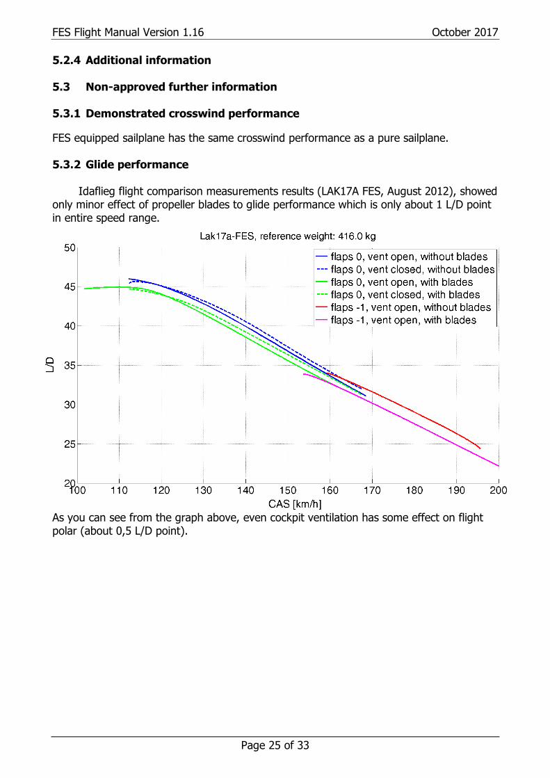
Idaflieg flight comparison measurements results (LAK17A FES, August 2012), showed only minor effect of propeller blades to glide performance which is only about 1 L/D point in entire speed range.
As you can see from the graph above, even cockpit ventilation has some effect on flight polar (about 0,5 L/D point).
FES Flight Manual Version 1.16 October 2017
Page 26 of 33
5.3.3 Flight polar
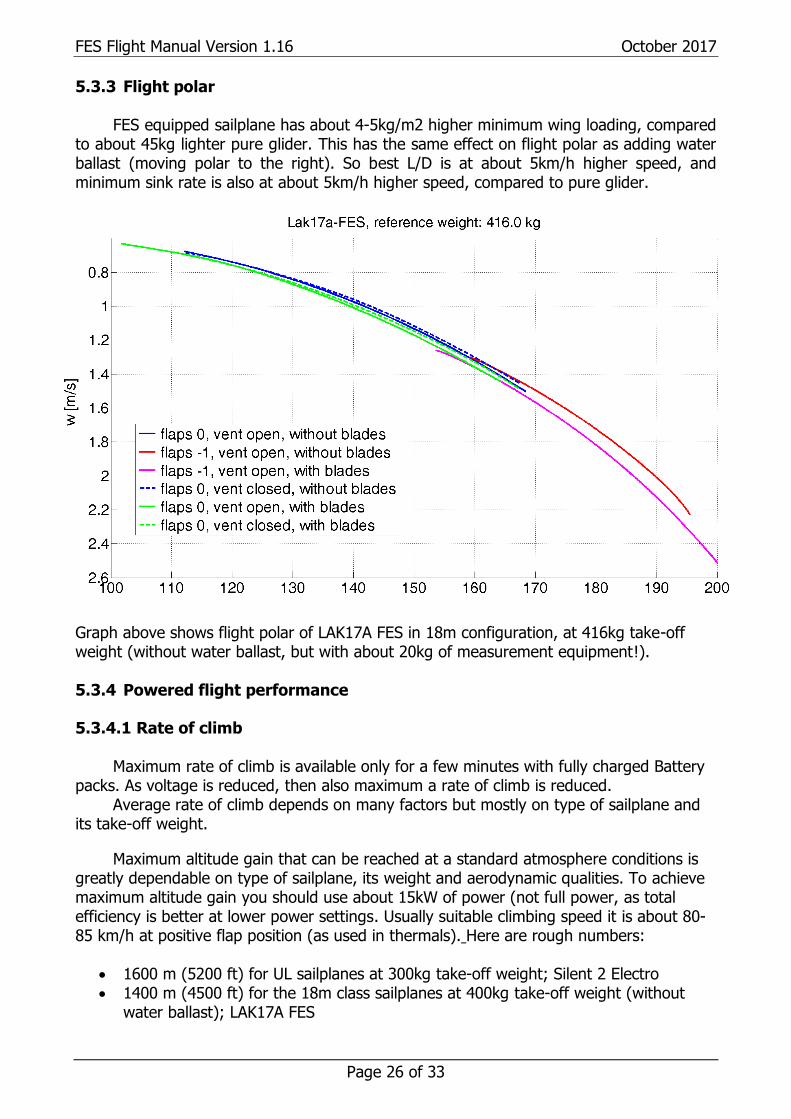
FES equipped sailplane has about 4-5kg/m2 higher minimum wing loading, compared to about 45kg lighter pure glider. This has the same effect on flight polar as adding water ballast (moving polar to the right). So best L/D is at about 5km/h higher speed, and minimum sink rate is also at about 5km/h higher speed, compared to pure glider.
Graph above shows flight polar of LAK17A FES in 18m configuration, at 416kg take-off weight (without water ballast, but with about 20kg of measurement equipment!). 5.3.4 Powered flight performance
5.3.4.1 Rate of climb
Maximum rate of climb is available only for a few minutes with fully charged Battery packs. As voltage is reduced, then also maximum a rate of climb is reduced.
Average rate of climb depends on many factors but mostly on type of sailplane and its take-off weight.
Maximum altitude gain that can be reached at a standard atmosphere conditions is greatly dependable on type of sailplane, its weight and aerodynamic qualities. To achieve maximum altitude gain you should use about 15kW of power (not full power, as total efficiency is better at lower power settings. Usually suitable climbing speed it is about 80-85 km/h at positive flap position (as used in thermals). Here are rough numbers:
• 1600 m (5200 ft) for UL sailplanes at 300kg take-off weight; Silent 2 Electro • 1400 m (4500 ft) for the 18m class sailplanes at 400kg take-off weight (without
water ballast); LAK17A FES
FES Flight Manual Version 1.16 October 2017
Page 27 of 33
• 1200 m (3900 ft) for the 18m class sailplanes at 450kg take-off weight (without
water ballast); LAK17B FES, Ventus 2cxa FES, Discus 2c FES, HPH 304ES
Caution: Always take care that propeller blades are cleaned. Unclean leading edge reduces propeller efficiency, and climb rate.
5.3.4.2 Cruising flight
The maximum range of powered cruising flight, without water ballast is about 100km (62 miles), depending on lift-sink conditions.
The optimum cruising speed and flap position depends on type of sailplane. Usually it
is about 90 km/h (48 kts) at around 3000-3300 RPM and 4kW of power, at positive (as used in thermals) position of flaps.
5.3.4.3 Maximum operational altitude
There should be no problem to fly with FES equipped sailplane on high altitudes, due to low pressure. According UN transport regulations such cells which are used in FES battery packs had to pass 8 different tests. First test is altitude simulation where cells were tested at reduced pressure of 11.6kPa which is equivalent of about 15.000m.
Cold outside temperatures down to -20 °C do not represent a safety issue for Battery
packs (as they usually stay much warmer), or for other components of FES system.
However, if Battery packs have very low temperature their performance is reduced, but it
is unlikely that you will need to use FES at high altitude.
5.3.5 Noise data
Measurements of noise level of motor are lower than levels of noise compared to sailplanes equipped with combustion engines.
Measurement was performed for certification purposes of Silent 2 Electro, where noise level was measured to be 57 db, according requirements.
For sustainers there are no requirements regarding maximal noise level.
Regarding ENL (Engine Noise Level) signal for Flight recorder:
It should be emphasized that for the ENL signal to be significant when the FES is running, the Flight Recorder must be mounted in the instrument panel or equally close to the FES unit. Mounting of the FR elsewhere in the cockpit will require a separate MOP sensor in the same way as for other quiet electric engines.
Annex B to the IGC Sporting Code refers. 5.3.6 Electromagnetic interferences
Good construction of motor does not leak magnetic field outside of its housing. With high power cables going below instrument panel, we did not find any strange behaviour of any instruments (including magnetic compass) during motor run or stop.
FES Flight Manual Version 1.16 October 2017
Page 28 of 33
6. Weight and balance 6.1 Introduction At each FES equipped sailplane, positioning of FES elements should be arranged in such a way, that C.G. position remains in nearly the same range as at pure sailplane. 6.2 Weight and Balance Record and permitted payload-range As it is valid for a pure version or powered version of specific sailplane type. 6.3 Weight of all non-lifting parts Weight of non-lifting parts of the sailplane includes weight of pilot, fuselage with rudder, horizontal stabilizer with elevator, instruments and equipment and weight of FES installation (everything except wings). Maximum weight of non-lifting parts for specific type of sailplane is set by manufacturer. 6.4 Maximum weight
The maximum approved take-off and landing weight is set by sailplane manufacturer.
Warning: Do not use full amount of water ballast as there is already about 50kg of additional weight due to FES system installation. Adjust maximum amount of water ballast, so that you will not fly above allowed maximum take-off weight, otherwise you can overload your sailplane, resulting in structural damage of airframe.
FES Flight Manual Version 1.16 October 2017
Page 29 of 33
7. General sailplane and systems description 7.1 Introduction
This Chapter provides a description of the sailplane, its systems and provided standard equipment with instructions for use. 7.2 Cockpit controls
Apart from standard controls of pure sailplane, FES equipped sailplane, has only additional Power switch, located on right side of cockpit (toggle switch with cover), or on instrument panel console (key switch), depending on type of sailplane. 7.3 Instrument panel
Apart from other instruments located on instrument panel, FES equipped sailplane, has only additional FCU instrument, which should be located on easily accessible location on left side of panel. Most suitable location is dependable on specific glider type and other installed instruments.
Detailed description of FCU can be found in separate FCU instrument manual. 7.4 Landing gear system As written in flight manual of pure sailplane! 7.5 Seats and safety harness As written in flight manual of pure sailplane! 7.6 Pitot and static system
The airspeed indicator is to be connected to the pitot source from the fuselage vertical stabilizer and static source from the aft fuselage part (detailed location of ports depends on specific glider type).
At FES equipped sailplane, pitot source cannot be located on the fuselage nose! Note: Consult with sailplane manufacturer, regarding optimal configuration of pneumatic sources for specific FES equipped type of sailplane. For more info about measuring probes visit www.esa-systems.com.
Total energy compensation source is normally from the fuselage vertical stabilizer,
below pitot source. When FES is installed into used sailplane and there is only one tube available (for
total energy compensation but not for pitot), then this tube is taken for pitot source. In such case, electronic compensation can be used. 7.7 Air brakes system As written in flight manual of pure sailplane!

FES Flight Manual Version 1.16 October 2017
Page 30 of 33
7.8 Baggage Compartment As written in flight manual of pure sailplane.
Warning: If you are heavier pilot, than weigh of non-lifting parts on a FES equipped sailplane are already close to the approved limit of manufacturer, especially if you are using also tail water ballast. So heavy pilots should avoid using any additional weight in baggage compartment!
7.9 Water ballast system As written in flight manual of pure sailplane.
Caution: When filling water ballast into wings, make sure, the cover for battery compartment is closed!
7.10 Power plant
Detailed description of FES power plant can be found in FES maintenance manual, where are also listed other manuals for specific type of FES equipped sailplane. 7.11 Battery packs
Detailed description of FES Battery packs can be found in FES Battery packs manual. 7.12 Electrical system
Detailed description of FES electrical system can be found in FES maintenance manual 7.13 Miscellaneous equipment
Detailed description of FES BMS (Battery management system), FES Battery pack charger and BMS Control software can be found in FES Battery packs manual.
FES Flight Manual Version 1.16 October 2017
Page 31 of 33
8. Sailplane handling, care and maintenance 8.1 Introduction
This chapter contains the manufacturer's recommended procedures for proper handling and servicing of the sailplane with FES. It also identifies certain inspection and maintenance activities, which are needed to retain performance and dependability. 8.2 FES inspection periods
The Instructions for Continued Airworthiness as provided in the FES Maintenance manual must be followed. 8.3 Sailplane alterations or repairs As described in manual for pure sailplane version. 8.4 Ground handling / road transport a) Towing / Pushing
General information as described in manual for pure sailplane version. On the ground propeller blades should be protected with a special blade protection covers, which prevents propeller blades from opening. Do not forget to remove propeller covers before flight! On some newer FES gliders, propeller tips have integrated metal plates and small permanent magnet is integrated in the fuselage to hold propeller blades folded. In this case protection covers can be used too, but they are not necessary!
Caution: Make sure that propeller is in horizontal position when lifting rear part of fuselage to attach tail dolly. Warning: Newer use a propeller or spinner for pushing, pulling or tail lifting!
b) Hangaring General information as described in manual for pure sailplane version. For storage of the FES-Batteries specific instructions must be observed. See FES BATTERY PACK GEN2 manual, section 8. c) Tie down
In dry conditions when rain is not expected during night, canopy cover is sufficient to protect motor from moisture. The FES batteries must be protected against moisture. In dry conditions is sufficient to tape cover. When rain is expected do not leave FES equipped sailplane outside on the rain, unless is covered with high quality all weather covers. It is recommended to remove FES batteries out of the glider and store them in dry place!
FES Flight Manual Version 1.16 October 2017
Page 32 of 33
d) Preparation for road transport
Warning: If sailplane is parked, stored or transported, then the connecting cable of the FES-batteries must be removed!
e) Transport of not installed Batteries
If the batteries are carried by the carrier strap by hand, then care must be taken to prevent that the batteries suffer any mechanical damage, e.g. by falling down, hitting on edges or similar. Furthermore, the batteries must be protected against moisture.
If the not installed batteries are transported (e.g. by car, in the trailer or similar), then they must be protected against mechanical damage and moisture. For the protection against mechanical damage a solid box must be used. It is recommended to use original FES transport boxes.
For safety reasons, transport box should be placed into the luggage compartment, if possible pushed forward up to the front wall. Transportation box should be additionally secured, so that it cannot move backward during acceleration, or forward at braking.
Warning: For safety reasons it is not allowed to transport battery packs in the car cockpit, for instance behind drivers or co-driver’s seat, or in front of the co-driver seat, as in case of accident it could be very dangerous! Note: It is not recommended to transport battery packs in the front area of glider trailer. In heavy rain most front hatches leak water, which could spill over battery packs.
Caution: Do not leave battery packs in the parked car or trailer under sun in hot summer, as they might be exposed to high temperatures.
FES Flight Manual Version 1.16 October 2017
Page 33 of 33
8.5 Sailplane trailer
A sailplane with FES should be transported and stored in a high quality enclosed trailer constructed of metal or fibre glass reinforced plastics with a proper insulation, and ventilation characteristics.
• For lighter fuselages forward and jumping motion of the fuselage restriction
could be arranged with a nose cone support in shape of spinner with a big enough recess for propeller blades in horizontal position, covered with a soft thick material.
• For heavier fuselages is recommended that support which holds fuselage is
arranged behind a spinner, otherwise load on motor and propeller blades could be too high (for Cobra trailers such suitable nose cone is optional).
It is recommended to use soft cotton canopy cover which goes also around
spinner nose of sailplane, which than also prevent opening of propeller blades. If canopy cover is not used than propeller blades should have fitted a cover with
elastic, which also prevent opening propeller blades! Newer FES gliders have metal plates in tips of the propeller blades. On fuselage is
installed magnet on suitable position, which holds propeller blades in aligned with the fuselage contour.
The fuselage should be supported in a fuselage dolly positioned just forward of the main landing wheel opening. Forward stop must be provided for the fuselage dolly Otherwise it will roll forward and leave the fuselage with no support. 8.6 Cleaning and care
Avoid cleaning with water around area of FES motor, and battery compartment. Spinner and propeller blades should be cleaned with a wet sponge or soft cotton towel. Tape adhesives are best removed using pure petroleum spirits or nitro thinner.
9. Supplements
There are no supplements
10. Revision history
April 2013 Initial release of manual v1.0
October 2013 Minor updates, v1.1
February 2014 Minor updates, v1.11
June 2015 Minor updates, v1.12
February 2016 Minor updates, v1.13
September 2016 Minor updates, v1.14
November 2016 New three view drawings, v1.15
October 2017 New info about fire detection system, v1.16


