Page 1
Ingenieurbüro für konstruktiven Ingenieurbau Dr.-Ing. Ingo Lukas
Am Krummen Morgen 1 67727 Lohnsfeld Tel. 06302 - 982844 Fax 06302 - 982846
Structural Analysis Power Plant Köln Niehl
Pipeline N3PAB50
Pipeline N3PAB09
Kom 1100/1150
Client: FKT Fassbender GmbH
Bonvitaweg 1-5
53424 Remagen-Kripp
Prepared : Lohnsfeld, 21. November 2013
Ingenieurbüro für konstruktiven Ingenieurbau
Dr.-Ing. Ingo Lukas
(Dr.-Ing. Ingo Lukas)
Page 2
Project: Power Plant Köln Niehl Page 2 Pipeline N3PAB50 u. N3PAB09
Client: FKT Fassbender GmbH
Contents
1. GENERAL .................................................................................................................................................. 3
2. REDUCTION FACTORS AND REQUIRED SECURITIES ........................................................................ 3
3. PERMISSIBLE EXPANSIONS ................................................................................................................... 4
4. LOADING ................................................................................................................................................... 4
4.1 DEADWEIGHT ......................................................................................................................................... 4 4.2 PRESSURE ............................................................................................................................................. 4 4.3 FILLING .................................................................................................................................................. 5 4.4 TEMPERATURE ....................................................................................................................................... 5 4.5 HYDROSTATIC UPLIFT ............................................................................................................................. 5 4.6 LOADING DUE TO SOIL ............................................................................................................................. 6 4.7 TRAFFIC LOAD ........................................................................................................................................ 6 4.8 GROUNDWATER ..................................................................................................................................... 6 4.9 SETTLEMENT .......................................................................................................................................... 6 4.10 EARTHQUAKE ......................................................................................................................................... 7
5. PIPE DESIGN ............................................................................................................................................ 8
5.1 PROOF OF THE TENSIONS IN LENGTHWISE DIRECTION UNDERGROUND PIPELINES ..................................... 8 5.2 PROOF OF THE TENSIONS IN CIRCUMFERENTIAL DIRECTION UNDERGROUND PIPELINES ............................. 8 5.3 STABILITY ANALYSIS UNDERGROUND PIPELINES .................................................................................... 26
6. DETAIL PROOFS .................................................................................................................................... 31
6.1 JOINT LAMINATES ................................................................................................................................. 31 6.2 OPENINGS............................................................................................................................................ 32 6.3 FLANGE DESIGN ................................................................................................................................... 38 6.4 SUPPORT REACTIONS DUE TO LENGTHWISE LOADINGS .......................................................................... 45 6.5 WALL RING AT FIX POINTS .................................................................................................................... 47 6.6 HEAD DN 2000 .................................................................................................................................... 48
7. MATERIAL DATA ..................................................................................................................................... 50
Page 3
Project: Power Plant Köln Niehl Page 3 Pipeline N3PAB50 u. N3PAB09
Client: FKT Fassbender GmbH
1. General
Object of this analysis is the design for the underground cooling water lines N3PAB50 and N3PAB09 of the
Power Plant Köln-Niehl.
The substantial parts of the pipings are made in the winding mode method of a Winding-Laminat. With a
winding angle of 54°.The joint laminates are produced of mixed laminat. The connection of the single sec-
tions of the pipeline results from inner and outer joint laminates.
All parts receive a fleece layer on the inner side which serves as a protective layer.
The following materials are being used as amplifictaion material: Protection layer - C - or E - CR - glas - fleece Traglaminat - E - and E – CR respectively - glas The following matrix materials are used: Derakane 411 basis of calculation:
Spool Drawings FKT GmbH material: look at the paragraph material data
literature: [1] Berechnungsempfehlungen für stehende Behälter aus glasfaserverstärkten Kunstoffen,
- IfBt - Berlin, Oktober 1998
[2] AD-Merkblatt 2000
[3] DIN 18800 Teil 4
[4] DIN 1055
[5] DIN 18820
[6] DIN V2505
[7] DIN 1055
[8] mb-Software AG: Handbuch zum Programmsystem MicroFE; Hameln 2001 [9] Worksheet A 127 der ATV AD-N1.
2. Reduction Factors and Required Securities
Because the time of charge, the temperature and the filling medium of the Storage Tank have a great effect
on GRP, the loadings have to be increased by A-values and a global security factor S
stress analysis:
8,2 321 mBmB AAAA
stability analysis:
1,89 321 SAAASA II
Page 4
Project: Power Plant Köln Niehl Page 4 Pipeline N3PAB50 u. N3PAB09
Client: FKT Fassbender GmbH
Material safety m
m = 1,40 If there are no temperature or media impacts, the respective coefficients are not required.
The following applies to all laminates used on the seperator:
A2 = 1,10 (influence of the medium) A3 = 1,26 (influence of the temperature)
If there are no temperature or media impacts, the respective coefficients are not required.
Necessary safeties on the load side The necessary safeties on the load side can be taken from the load compilation of the component.
3. Permissible expansions
Underground Pipelines
All Laminate Types: zul = 0.50% Pipelines during Test
Winding laminates in circumferential direction during operation zul = 0.35%
Winding laminates in longitudinal direction during operation zul = 0.30%
Mixed laminates during operation zul = 0.35%
4. Loading
4.1 Deadweight
GF =18,00 kN/m³
tm ≤ ttr + SS
gE ≤ 2 .
. r
. 18
. tm
The consideration of the own weight of the laminate occurs intern of program by input of the shell thickness and the density of the laminate.
4.2 Pressure
Internal Design pressure pü = 500 kN/m
2
Internal Test pressure püT = 750 kN/m
2
Short time external Design pressure pu = 80 kN/m
2
Page 5
Project: Power Plant Köln Niehl Page 5 Pipeline N3PAB50 u. N3PAB09
Client: FKT Fassbender GmbH
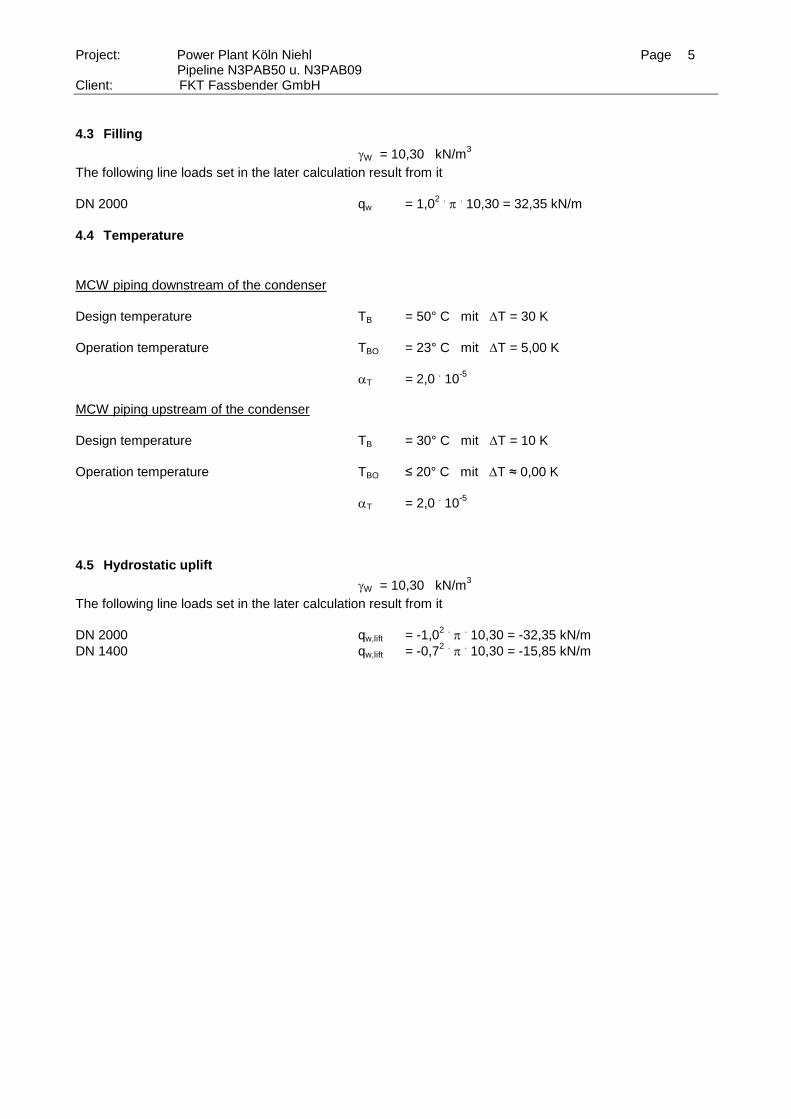
4.3 Filling
W = 10,30 kN/m3
The following line loads set in the later calculation result from it
DN 2000 qw = 1,02 .
. 10,30 = 32,35 kN/m
4.4 Temperature
MCW piping downstream of the condenser
Design temperature TB = 50° C mit T = 30 K
Operation temperature TBO = 23° C mit T = 5,00 K
T = 2,0 . 10
-5
MCW piping upstream of the condenser
Design temperature TB = 30° C mit T = 10 K
Operation temperature TBO ≤ 20° C mit T ≈ 0,00 K
T = 2,0 . 10
-5
4.5 Hydrostatic uplift
W = 10,30 kN/m3
The following line loads set in the later calculation result from it
DN 2000 qw,lift = -1,02 .
. 10,30 = -32,35 kN/m
DN 1400 qw,lift = -0,72 .
. 10,30 = -15,85 kN/m
Page 6
Project: Power Plant Köln Niehl Page 6 Pipeline N3PAB50 u. N3PAB09
Client: FKT Fassbender GmbH
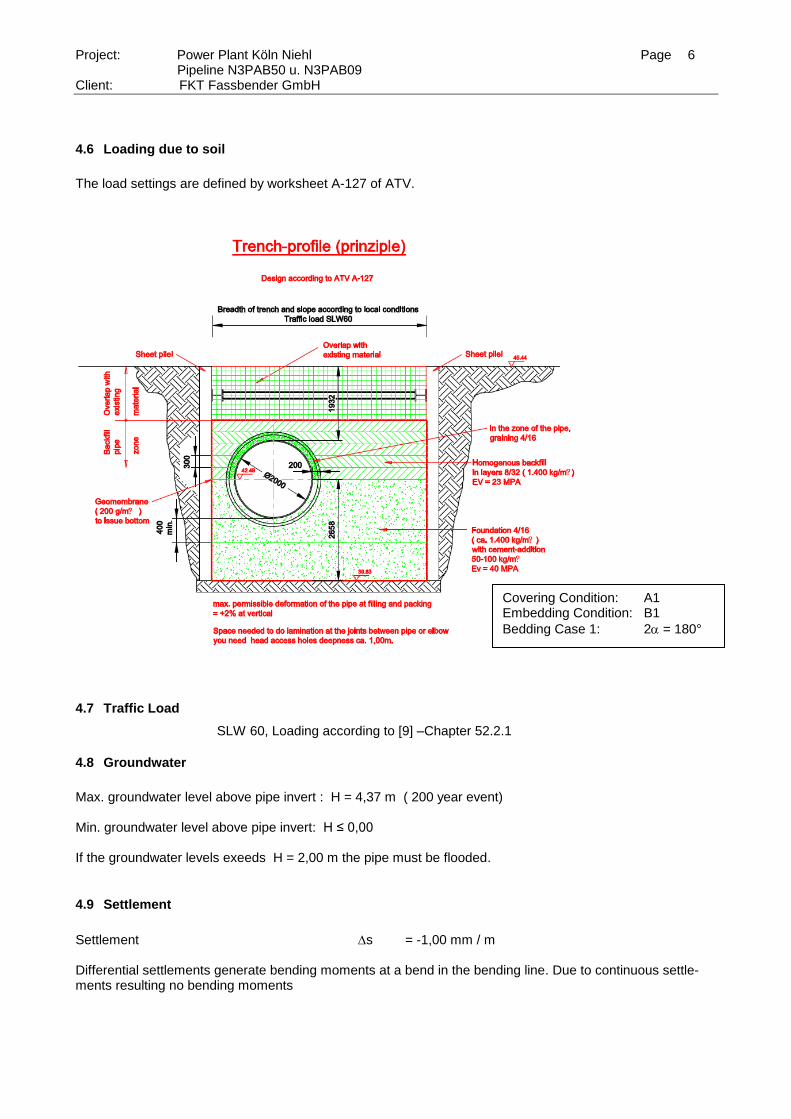
4.6 Loading due to soil
The load settings are defined by worksheet A-127 of ATV.
4.7 Traffic Load
SLW 60, Loading according to [9] –Chapter 52.2.1
4.8 Groundwater
Max. groundwater level above pipe invert : H = 4,37 m ( 200 year event) Min. groundwater level above pipe invert: H ≤ 0,00 If the groundwater levels exeeds H = 2,00 m the pipe must be flooded.
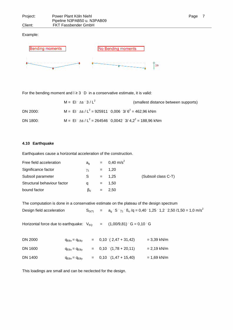
4.9 Settlement
Settlement s = -1,00 mm / m Differential settlements generate bending moments at a bend in the bending line. Due to continuous settle-ments resulting no bending moments
Covering Condition: A1 Embedding Condition: B1
Bedding Case 1: 2 = 180°
Page 7
Project: Power Plant Köln Niehl Page 7 Pipeline N3PAB50 u. N3PAB09
Client: FKT Fassbender GmbH
Example:
For the bending moment and l ≥ 3
. D in a conservative estimate, it is valid:
M = EI . s
. 3 / L
2 (smallest distance between supports)
DN 2000: M = EI . s / L
2 = 925911
. 0,006
. 3/ 6
2 = 462,96 kNm
DN 1800: M = EI . s / L
2 = 264546
. 0,0042
. 3/ 4,2
2 = 188,96 kNm
4.10 Earthquake
Earthquakes cause a horizontal acceleration of the construction. Free field acceleration ag = 0,40 m/s
2
Significance factor 1 = 1,20
Subsoil parameter S = 1,25 (Subsoil class C-T)
Structural behaviour factor q = 1,50
bound factor β0 = 2,50
The computation is done in a conservative estimate on the plateau of the design spectrum
Design field acceleration SD(T) = ag . S
. 1
. ßo /q = 0,40
. 1,25
. 1,2
. 2,50 /1,50 = 1,0 m/s
2
Horizontal force due to earthquake: VEQ = (1,00/9,81) . G = 0,10
. G
DN 2000 qEBx = qEBy = 0,10
. ( 2,47 + 31,42) = 3,39 kN/m
DN 1600 qEBx = qEBy = 0,10
. (1,78 + 20,11) = 2,19 kN/m
DN 1400 qEBx = qEBy = 0,10
. (1,47 + 15,40) = 1,69 kN/m
This loadings are small and can be neclected for the design.
Page 8
Project: Power Plant Köln Niehl Page 8 Pipeline N3PAB50 u. N3PAB09
Client: FKT Fassbender GmbH
5. Pipe Design
The design of the pipes results from the construction principle and the calculation references of the DIBt and
the worksheet A-127 of ATV.
5.1 Proof of the Tensions in lengthwise direction Underground Pipelines
Pipe DN 2000, t = 19,50 mm
Pressure: l,p = 0,50 . 500 /19,50 = 12,82 N/mm
2
Settlement: l,S = 492,96/ ( .19,50) = 8,04 N/mm
2
l = 1,5 . (1,5
. 12,82+ 8,04) = 40,91 N/mm
2 ≤ l,zul = 130/ ( 1,10
. 1,26
. 1,40) = 67,00 N/mm
2
l = 100
. (12,82+ 8,04)/(1,1
. 120000) = 0,19 % ≤ 0,25 %
Pipe DN 1400, t = 16,50 mm
Pressure: l,p = 0,35 . 500 /16,50 = 10,60 N/mm
2
Settlement: l,S = 188,96/ ( . 0,7
2 . 16,5) = 7,34 N/mm
2
l = 1,5 . (1,5
. 10,60 + 7,34 ) = 34,86 N/mm
2 ≤ l,zul = 130/ ( 1,10
. 1,26
. 1,40) = 67,00 N/mm
2
l = 100
. (10,60+ 7,34)/(1,1
. 120000) = 0,14 % ≤ 0,25 %
5.2 Proof of the Tensions in circumferential direction Underground Pipelines
The underground pipes are calculated with the worksheet A-127 of ATV. Condition for the approach is that
the pipes are grounded correspondent to the demands. It means that the support angle is ≥ 180°, the
grounding occurs in layers and a compaction of the ground ≥ 95 % Proctor is given.
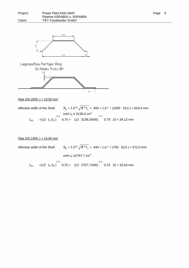
For the pipeline with stiffening rings two proofs are carried out, the area of the ribs and the intermediate re-
gion. The area between the rips gets only the loading due to soil. The ring section takes the load of the soil
and an additional traffic load due to SLW 60.
When the pipe parts that are charged by the specified traffic load, the following approach for the determina-
tion of internal loads is chosen for the calculation of ring:
LR = t3ers
.
lR /12
ters =(12 . IR /LR )
1/ 3 . 0,75
LR : Distance between Stiffners
IR: Moment of inertia of the ringstffner
ters: Substitute thickness pipe in the area of the ribs
The following picture shows the used ringstiffner.
Page 9
Project: Power Plant Köln Niehl Page 9 Pipeline N3PAB50 u. N3PAB09
Client: FKT Fassbender GmbH
Pipe DN 2000, t = 19,50 mm
effective width of the Shell zR tRb **6.1 = 400 + 1,6 * (1000 . 19,5 ) = 623,4 mm
vorh IR ≥ 3139,3 cm4
ters =(12 . IR /lR )
1/ 3 . 0,75 = (12
. 3139,3/400)
1/ 3 . 0,75
. 10 = 34,12 mm
Pipe DN 1400, t = 14,50 mm
effective width of the Shell zR tRb **6.1 = 440 + 1,6 * (700 . 16,5 ) = 572,0 mm
vorh IR ≥2757,7 cm
4
ters =(12 . IR /lR )
1/ 3 . 0,75 = (12
. 2757,7/400)
1/ 3 . 0,75
. 10 = 32,63 mm
Page 10
Project: Power Plant Köln Niehl Page 10 Pipeline N3PAB50 u. N3PAB09
Client: FKT Fassbender GmbH
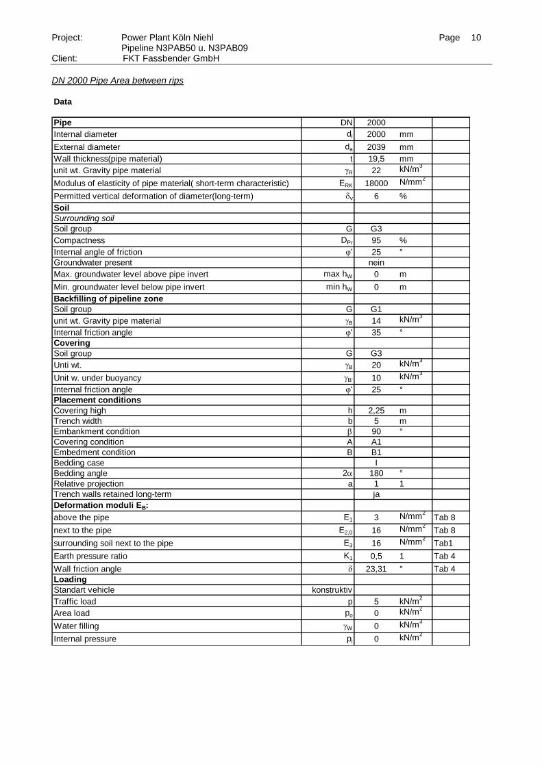
DN 2000 Pipe Area between rips Data
Pipe DN 2000
Internal diameter di 2000 mm
External diameter da 2039 mm
Wall thickness(pipe material) t 19,5 mm
unit wt. Gravity pipe material R 22 kN/m3
Modulus of elasticity of pipe material( short-term characteristic) ERK 18000 N/mm2
Permitted vertical deformation of diameter(long-term) dv 6 %
Soil
Surrounding soil
Soil group G G3
Compactness DPr 95 %
Internal angle of friction j' 25 °
Groundwater present nein
Max. groundwater level above pipe invert max hW 0 m
Min. groundwater level below pipe invert min hW 0 m
Backfilling of pipeline zone
Soil group G G1
unit wt. Gravity pipe material B 14 kN/m3
Internal friction angle j' 35 °
Covering
Soil group G G3
Unti wt. B 20 kN/m3
Unit w. under buoyancy B' 10 kN/m3
Internal friction angle j' 25 °
Placement conditions
Covering high h 2,25 m
Trench width b 5 m
Embankment condition b 90 °
Covering condition A A1
Embedment condition B B1
Bedding case I
Bedding angle 2 180 °
Relative projection a 1 1
Trench walls retained long-term ja
Deformation moduli EB:
above the pipe E1 3 N/mm2
Tab 8
next to the pipe E2,0 16 N/mm2
Tab 8
surrounding soil next to the pipe E3 16 N/mm2
Tab1
Earth pressure ratio K1 0,5 1 Tab 4
Wall friction angle d 23,31 ° Tab 4
Loading
Standart vehicle konstruktiv
Traffic load p 5 kN/m2
Area load po 0 kN/m2
Water filling W 0 kN/m3
Internal pressure pi 0 kN/m2
Page 11
Project: Power Plant Köln Niehl Page 11 Pipeline N3PAB50 u. N3PAB09
Client: FKT Fassbender GmbH
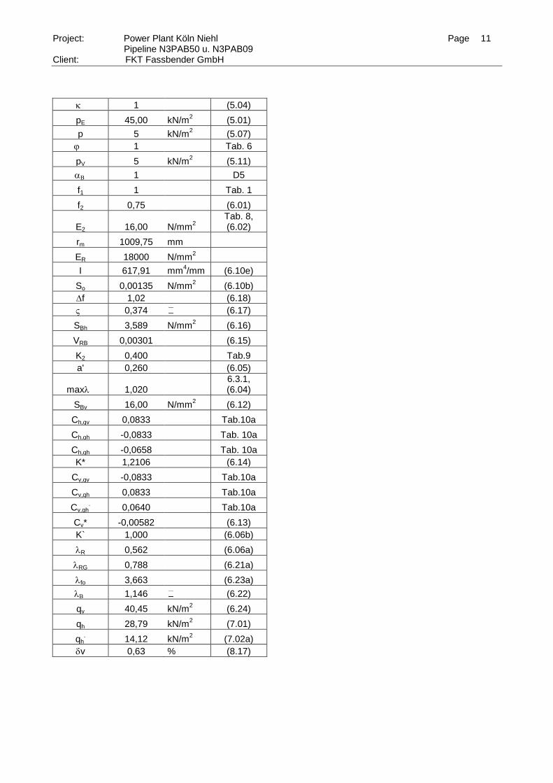
1 (5.04)
pE 45,00 kN/m2 (5.01)
p 5 kN/m2 (5.07)
j 1 Tab. 6
pV 5 kN/m2 (5.11)
1 D5
f1 1 Tab. 1
f2 0,75 (6.01)
E2 16,00 N/mm2
Tab. 8, (6.02)
rm 1009,75 mm
ER 18000 N/mm2
I 617,91 mm4/mm (6.10e)
So 0,00135 N/mm2 (6.10b)
f 1,02 (6.18)
0,374 (6.17)
SBh 3,589 N/mm2 (6.16)
VRB 0,00301 (6.15)
K2 0,400 Tab.9
a' 0,260 (6.05)
max 1,020 6.3.1, (6.04)
SBv 16,00 N/mm2 (6.12)
Ch,qv 0,0833 Tab.10a
Ch,qh -0,0833 Tab. 10a
Ch,qh -0,0658 Tab. 10a
K* 1,2106 (6.14)
Cv,qv -0,0833 Tab.10a
Cv,qh 0,0833 Tab.10a
Cv,qh.
0,0640 Tab.10a
Cv* -0,00582 (6.13)
K` 1,000 (6.06b)
R 0,562 (6.06a)
RG 0,788 (6.21a)
fo 3,663 (6.23a)
1,146 (6.22)
qv 40,45 kN/m
2 (6.24)
qh 28,79 kN/m2 (7.01)
qh. 14,12 kN/m
2 (7.02a)
dv 0,63 % (8.17)
Page 12
Project: Power Plant Köln Niehl Page 12 Pipeline N3PAB50 u. N3PAB09
Client: FKT Fassbender GmbH
Internal Forces and Tensions Support angle 2 = 180° Internal Forces in kN Bending Moments in kNm Tensions in N/mm
2
Coefficients
mqv mqh mqh* mg mw
Crown 0,250 -0,250 -0,181 0,345 0,172 Haunch -0,250 0,250 0,208 -0,393 -0,196 Invert 0,250 -0,250 -0,181 0,441 0,220
nqv nqh nqh* ng mw
Crown 0,000 -1,000 -0,577 0,167 0,583 Haunch -1,000 0,000 0,000 -1,571 0,215 Invert 0,000 -1,000 -0,577 -0,167 1,417
Bending Moments and Normal forces
Mqv Mqh Mqh* Mg Mw Summe
Crown 10,311 -7,338 -2,606 0,123 1,771 2,262
Haunch -10,311 7,338 2,995 0,000 -2,018 -1,996
Invert 10,311 -7,338 -2,606 0,008 2,265 2,640
Nqv Nqh Nqh* Ng Nw Summe
Crown 0,000 -29,067 -8,228 0,030 5,944 -31,320
Haunch -40,846 0,000 0,000 0,000 2,192 -38,654
Invert 0,000 -29,067 -8,228 0,000 14,448 -22,847
mit
rm 1009,75 mm s 19,5 mm
Page 13
Project: Power Plant Köln Niehl Page 13 Pipeline N3PAB50 u. N3PAB09
Client: FKT Fassbender GmbH
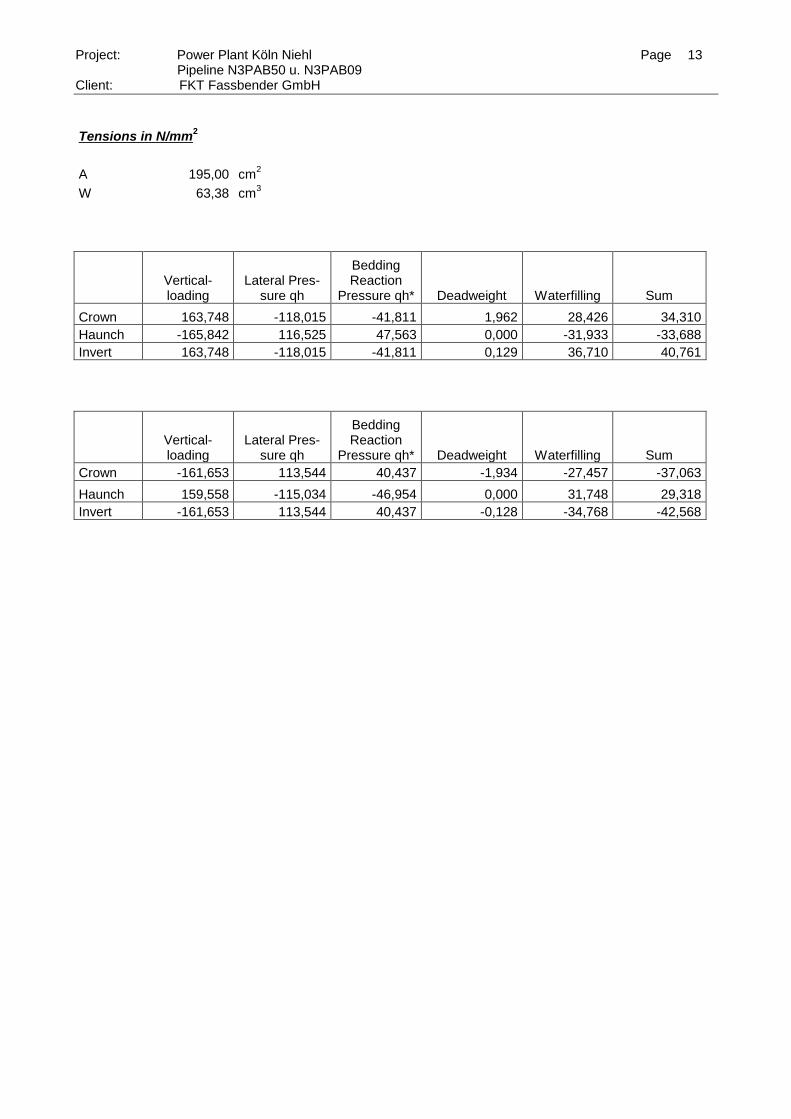
Tensions in N/mm2
A 195,00 cm2
W 63,38 cm3
Vertical- loading
Lateral Pres-sure qh
Bedding Reaction
Pressure qh* Deadweight Waterfilling Sum
Crown 163,748 -118,015 -41,811 1,962 28,426 34,310
Haunch -165,842 116,525 47,563 0,000 -31,933 -33,688
Invert 163,748 -118,015 -41,811 0,129 36,710 40,761
Vertical- loading
Lateral Pres-sure qh
Bedding Reaction
Pressure qh* Deadweight Waterfilling Sum
Crown -161,653 113,544 40,437 -1,934 -27,457 -37,063
Haunch 159,558 -115,034 -46,954 0,000 31,748 29,318
Invert -161,653 113,544 40,437 -0,128 -34,768 -42,568
Page 14
Project: Power Plant Köln Niehl Page 14 Pipeline N3PAB50 u. N3PAB09
Client: FKT Fassbender GmbH
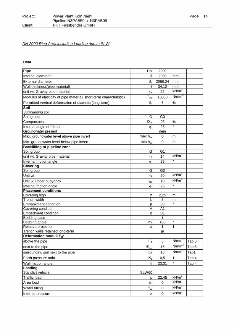
DN 2000 Ring Area including Loading due to SLW Data
Pipe DN 2000
Internal diameter di 2000 mm
External diameter da 2068,24 mm
Wall thickness(pipe material) t 34,12 mm
unit wt. Gravity pipe material R 22 kN/m3
Modulus of elasticity of pipe material( short-term characteristic) ERK 18000 N/mm2
Permitted vertical deformation of diameter(long-term) dv 6 %
Soil
Surrounding soil
Soil group G G3
Compactness DPr 95 %
Internal angle of friction j' 25 °
Groundwater present nein
Max. groundwater level above pipe invert max hW 0 m
Min. groundwater level below pipe invert min hW 0 m
Backfilling of pipeline zone
Soil group G G1
unit wt. Gravity pipe material B 14 kN/m3
Internal friction angle j' 35 °
Covering
Soil group G G3
Unti wt. B 20 kN/m3
Unit w. under buoyancy B' 10 kN/m3
Internal friction angle j' 25 °
Placement conditions
Covering high h 2,25 m
Trench width b 5 m
Embankment condition b 90 °
Covering condition A A1
Embedment condition B B1
Bedding case I
Bedding angle 2 180 °
Relative projection a 1 1
Trench walls retained long-term ja
Deformation moduli EB:
above the pipe E1 3 N/mm2
Tab 8
next to the pipe E2,0 16 N/mm2
Tab 8
surrounding soil next to the pipe E3 16 N/mm2
Tab1
Earth pressure ratio K1 0,5 1 Tab 4
Wall friction angle d 23,31 ° Tab 4
Loading
Standart vehicle SLW60
Traffic load p 22,45 kN/m2
Area load po 0 kN/m2
Water filling W 0 kN/m3
Internal pressure pi 0 kN/m2
Page 15
Project: Power Plant Köln Niehl Page 15 Pipeline N3PAB50 u. N3PAB09
Client: FKT Fassbender GmbH
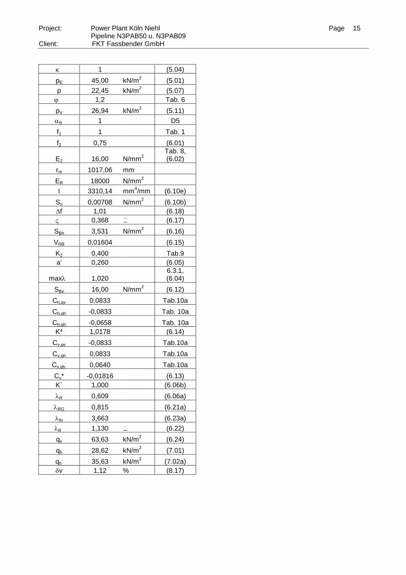
1 (5.04)
pE 45,00 kN/m2 (5.01)
p 22,45 kN/m2 (5.07)
j 1,2 Tab. 6
pV 26,94 kN/m2 (5.11)
1 D5
f1 1 Tab. 1
f2 0,75 (6.01)
E2 16,00 N/mm2
Tab. 8, (6.02)
rm 1017,06 mm
ER 18000 N/mm2
I 3310,14 mm4/mm (6.10e)
So 0,00708 N/mm2 (6.10b)
f 1,01 (6.18)
0,368 (6.17)
SBh 3,531 N/mm2 (6.16)
VRB 0,01604 (6.15)
K2 0,400 Tab.9
a' 0,260 (6.05)
max 1,020 6.3.1, (6.04)
SBv 16,00 N/mm2 (6.12)
Ch,qv 0,0833 Tab.10a
Ch,qh -0,0833 Tab. 10a
Ch,qh -0,0658 Tab. 10a
K* 1,0178 (6.14)
Cv,qv -0,0833 Tab.10a
Cv,qh 0,0833 Tab.10a
Cv,qh.
0,0640 Tab.10a
Cv* -0,01816 (6.13)
K` 1,000 (6.06b)
R 0,609 (6.06a)
RG 0,815 (6.21a)
fo 3,663 (6.23a)
1,130 (6.22)
qv 63,63 kN/m
2 (6.24)
qh 28,62 kN/m2 (7.01)
qh. 35,63 kN/m
2 (7.02a)
dv 1,12 % (8.17)
Page 16
Project: Power Plant Köln Niehl Page 16 Pipeline N3PAB50 u. N3PAB09
Client: FKT Fassbender GmbH
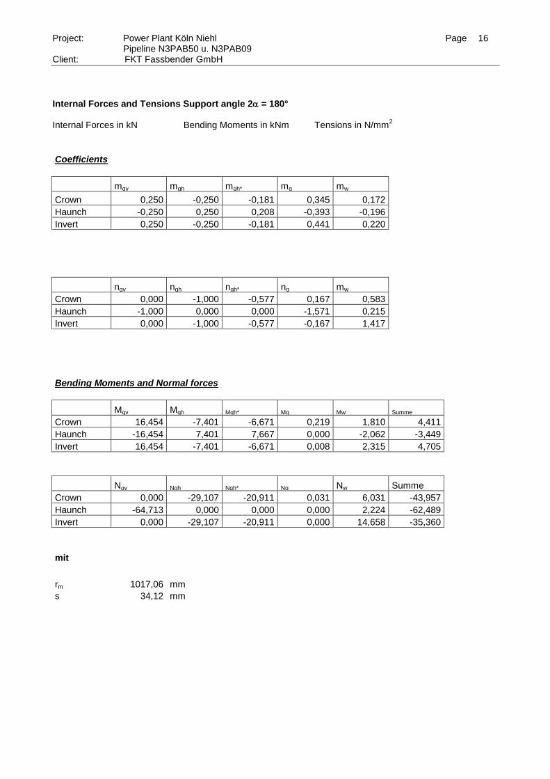
Internal Forces and Tensions Support angle 2 = 180° Internal Forces in kN Bending Moments in kNm Tensions in N/mm
2
Coefficients
mqv mqh mqh* mg mw
Crown 0,250 -0,250 -0,181 0,345 0,172 Haunch -0,250 0,250 0,208 -0,393 -0,196 Invert 0,250 -0,250 -0,181 0,441 0,220
nqv nqh nqh* ng mw
Crown 0,000 -1,000 -0,577 0,167 0,583 Haunch -1,000 0,000 0,000 -1,571 0,215 Invert 0,000 -1,000 -0,577 -0,167 1,417
Bending Moments and Normal forces
Mqv Mqh Mqh* Mg Mw Summe
Crown 16,454 -7,401 -6,671 0,219 1,810 4,411
Haunch -16,454 7,401 7,667 0,000 -2,062 -3,449
Invert 16,454 -7,401 -6,671 0,008 2,315 4,705
Nqv Nqh Nqh* Ng Nw Summe
Crown 0,000 -29,107 -20,911 0,031 6,031 -43,957
Haunch -64,713 0,000 0,000 0,000 2,224 -62,489
Invert 0,000 -29,107 -20,911 0,000 14,658 -35,360
mit
rm 1017,06 mm s 34,12 mm
Page 17
Project: Power Plant Köln Niehl Page 17 Pipeline N3PAB50 u. N3PAB09
Client: FKT Fassbender GmbH
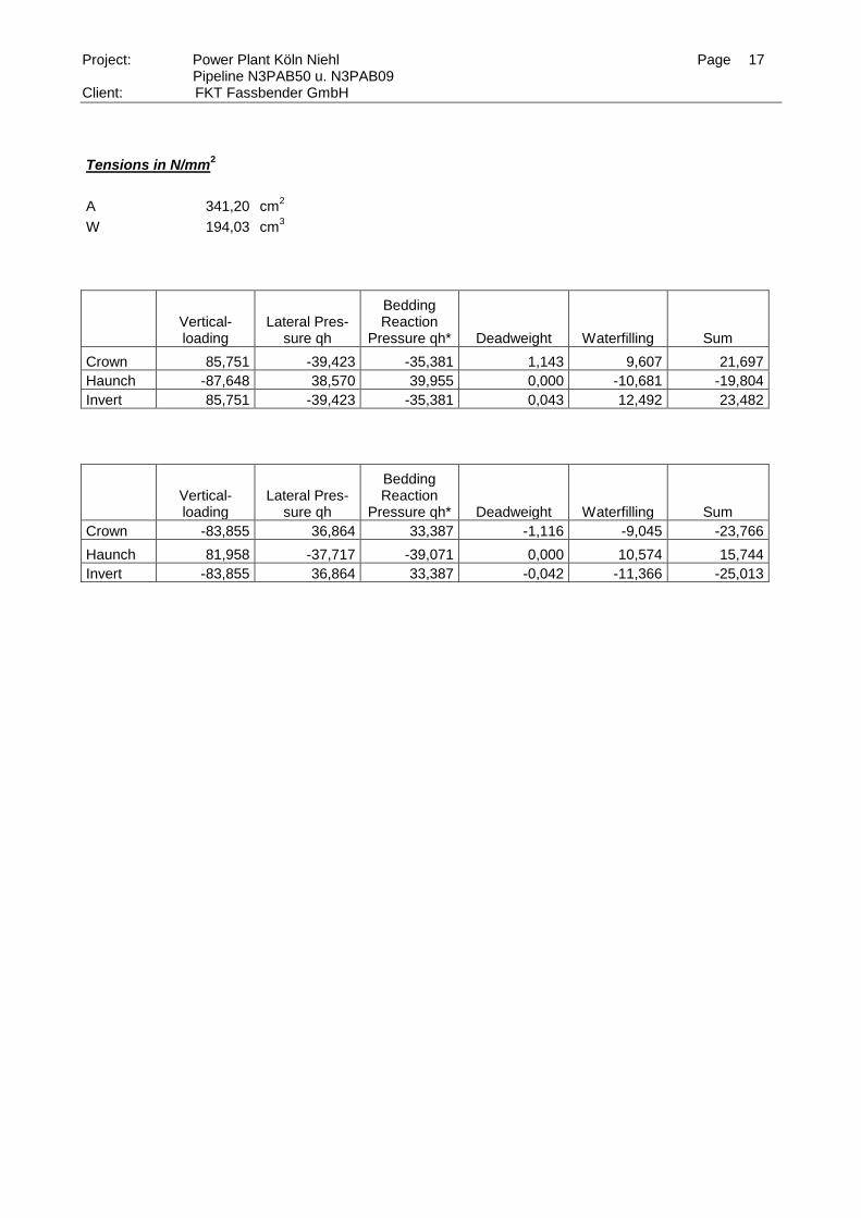
Tensions in N/mm2
A 341,20 cm2
W 194,03 cm3
Vertical- loading
Lateral Pres-sure qh
Bedding Reaction
Pressure qh* Deadweight Waterfilling Sum
Crown 85,751 -39,423 -35,381 1,143 9,607 21,697
Haunch -87,648 38,570 39,955 0,000 -10,681 -19,804
Invert 85,751 -39,423 -35,381 0,043 12,492 23,482
Vertical- loading
Lateral Pres-sure qh
Bedding Reaction
Pressure qh* Deadweight Waterfilling Sum
Crown -83,855 36,864 33,387 -1,116 -9,045 -23,766
Haunch 81,958 -37,717 -39,071 0,000 10,574 15,744
Invert -83,855 36,864 33,387 -0,042 -11,366 -25,013
Page 18
Project: Power Plant Köln Niehl Page 18 Pipeline N3PAB50 u. N3PAB09
Client: FKT Fassbender GmbH
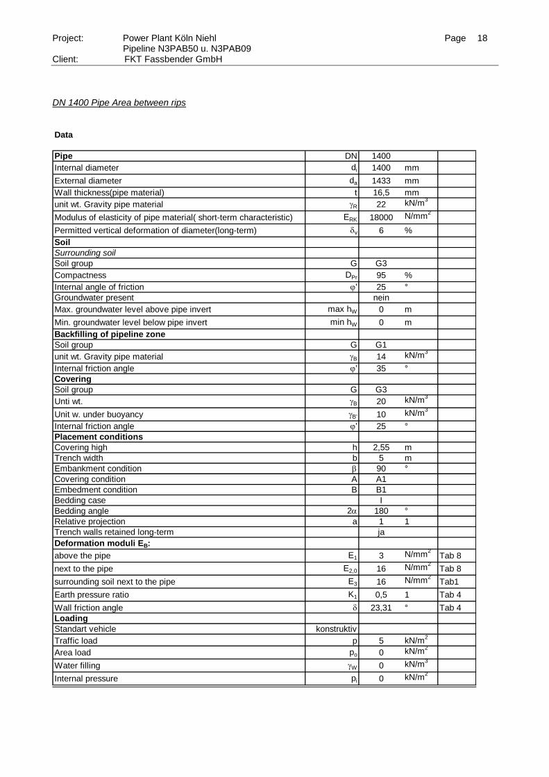
DN 1400 Pipe Area between rips Data
Pipe DN 1400
Internal diameter di 1400 mm
External diameter da 1433 mm
Wall thickness(pipe material) t 16,5 mm
unit wt. Gravity pipe material R 22 kN/m3
Modulus of elasticity of pipe material( short-term characteristic) ERK 18000 N/mm2
Permitted vertical deformation of diameter(long-term) dv 6 %
Soil
Surrounding soil
Soil group G G3
Compactness DPr 95 %
Internal angle of friction j' 25 °
Groundwater present nein
Max. groundwater level above pipe invert max hW 0 m
Min. groundwater level below pipe invert min hW 0 m
Backfilling of pipeline zone
Soil group G G1
unit wt. Gravity pipe material B 14 kN/m3
Internal friction angle j' 35 °
Covering
Soil group G G3
Unti wt. B 20 kN/m3
Unit w. under buoyancy B' 10 kN/m3
Internal friction angle j' 25 °
Placement conditions
Covering high h 2,55 m
Trench width b 5 m
Embankment condition b 90 °
Covering condition A A1
Embedment condition B B1
Bedding case I
Bedding angle 2 180 °
Relative projection a 1 1
Trench walls retained long-term ja
Deformation moduli EB:
above the pipe E1 3 N/mm2
Tab 8
next to the pipe E2,0 16 N/mm2
Tab 8
surrounding soil next to the pipe E3 16 N/mm2
Tab1
Earth pressure ratio K1 0,5 1 Tab 4
Wall friction angle d 23,31 ° Tab 4
Loading
Standart vehicle konstruktiv
Traffic load p 5 kN/m2
Area load po 0 kN/m2
Water filling W 0 kN/m3
Internal pressure pi 0 kN/m2
Page 19
Project: Power Plant Köln Niehl Page 19 Pipeline N3PAB50 u. N3PAB09
Client: FKT Fassbender GmbH
1 (5.04)
pE 51,00 kN/m2 (5.01)
p 5 kN/m2 (5.07)
j 1 Tab. 6
pV 5 kN/m2 (5.11)
1 D5
f1 1 Tab. 1
f2 0,75 (6.01)
E2 16,00 N/mm2
Tab. 8, (6.02)
rm 708,25 mm
ER 18000 N/mm2
I 374,34 mm4/mm (6.10e)
So 0,00237 N/mm2 (6.10b)
f 1,44 (6.18)
0,624 (6.17)
SBh 5,992 N/mm2 (6.16)
VRB 0,00317 (6.15)
K2 0,400 Tab.9
a' 0,260 (6.05)
max 1,026 6.3.1, (6.04)
SBv 16,00 N/mm2 (6.12)
Ch,qv 0,0833 Tab.10a
Ch,qh -0,0833 Tab. 10a
Ch,qh -0,0658 Tab. 10a
K* 1,2079 (6.14)
Cv,qv -0,0833 Tab.10a
Cv,qh 0,0833 Tab.10a
Cv,qh.
0,0640 Tab.10a
Cv* -0,00600 (6.13)
K` 1,000 (6.06b)
R 0,584 (6.06a)
RG 0,655 (6.21a)
fo 3,618 (6.23a)
1,139 (6.22)
qv 38,40 kN/m
2 (6.24)
qh 28,96 kN/m2 (7.01)
qh. 11,41 kN/m
2 (7.02a)
dv 0,30 % (8.17)
Page 20
Project: Power Plant Köln Niehl Page 20 Pipeline N3PAB50 u. N3PAB09
Client: FKT Fassbender GmbH
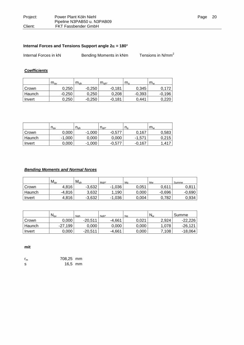
Internal Forces and Tensions Support angle 2 = 180° Internal Forces in kN Bending Moments in kNm Tensions in N/mm
2
Coefficients
mqv mqh mqh* mg mw
Crown 0,250 -0,250 -0,181 0,345 0,172 Haunch -0,250 0,250 0,208 -0,393 -0,196 Invert 0,250 -0,250 -0,181 0,441 0,220
nqv nqh nqh* ng mw
Crown 0,000 -1,000 -0,577 0,167 0,583 Haunch -1,000 0,000 0,000 -1,571 0,215 Invert 0,000 -1,000 -0,577 -0,167 1,417
Bending Moments and Normal forces
Mqv Mqh Mqh* Mg Mw Summe
Crown 4,816 -3,632 -1,036 0,051 0,611 0,811
Haunch -4,816 3,632 1,190 0,000 -0,696 -0,690
Invert 4,816 -3,632 -1,036 0,004 0,782 0,934
Nqv Nqh Nqh* Ng Nw Summe
Crown 0,000 -20,511 -4,661 0,021 2,924 -22,226
Haunch -27,199 0,000 0,000 0,000 1,078 -26,121
Invert 0,000 -20,511 -4,661 0,000 7,108 -18,064
mit
rm 708,25 mm s 16,5 mm
Page 21
Project: Power Plant Köln Niehl Page 21 Pipeline N3PAB50 u. N3PAB09
Client: FKT Fassbender GmbH
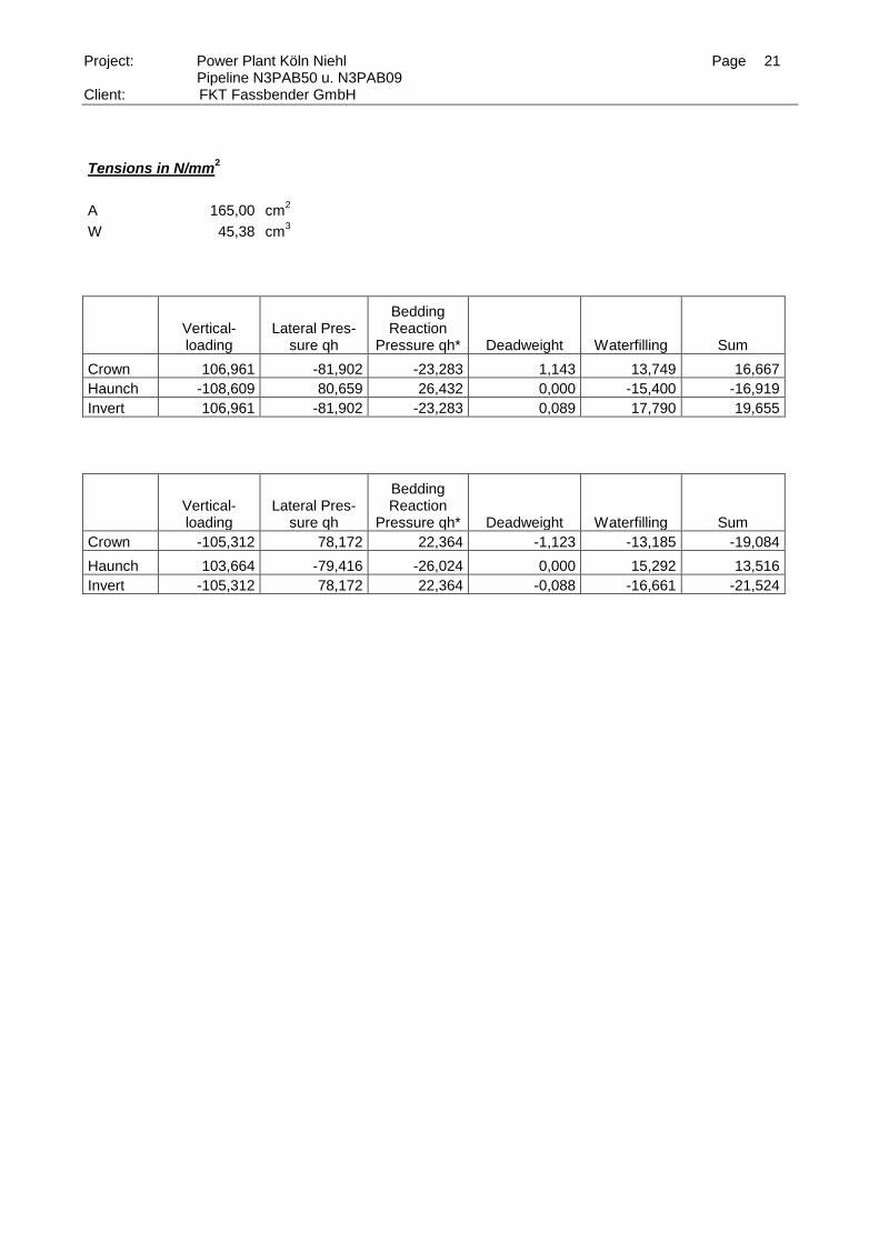
Tensions in N/mm2
A 165,00 cm2
W 45,38 cm3
Vertical- loading
Lateral Pres-sure qh
Bedding Reaction
Pressure qh* Deadweight Waterfilling Sum
Crown 106,961 -81,902 -23,283 1,143 13,749 16,667
Haunch -108,609 80,659 26,432 0,000 -15,400 -16,919
Invert 106,961 -81,902 -23,283 0,089 17,790 19,655
Vertical- loading
Lateral Pres-sure qh
Bedding Reaction
Pressure qh* Deadweight Waterfilling Sum
Crown -105,312 78,172 22,364 -1,123 -13,185 -19,084
Haunch 103,664 -79,416 -26,024 0,000 15,292 13,516
Invert -105,312 78,172 22,364 -0,088 -16,661 -21,524
Page 22
Project: Power Plant Köln Niehl Page 22 Pipeline N3PAB50 u. N3PAB09
Client: FKT Fassbender GmbH
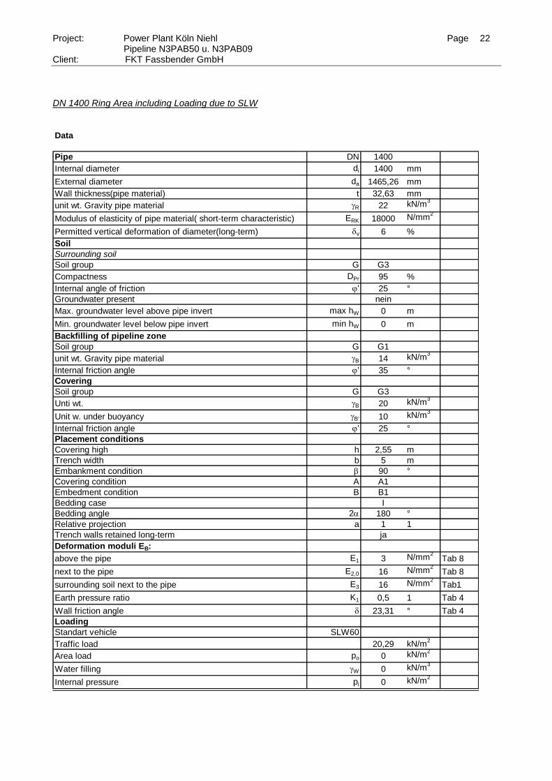
DN 1400 Ring Area including Loading due to SLW Data
Pipe DN 1400
Internal diameter di 1400 mm
External diameter da 1465,26 mm
Wall thickness(pipe material) t 32,63 mm
unit wt. Gravity pipe material R 22 kN/m3
Modulus of elasticity of pipe material( short-term characteristic) ERK 18000 N/mm2
Permitted vertical deformation of diameter(long-term) dv 6 %
Soil
Surrounding soil
Soil group G G3
Compactness DPr 95 %
Internal angle of friction j' 25 °
Groundwater present nein
Max. groundwater level above pipe invert max hW 0 m
Min. groundwater level below pipe invert min hW 0 m
Backfilling of pipeline zone
Soil group G G1
unit wt. Gravity pipe material B 14 kN/m3
Internal friction angle j' 35 °
Covering
Soil group G G3
Unti wt. B 20 kN/m3
Unit w. under buoyancy B' 10 kN/m3
Internal friction angle j' 25 °
Placement conditions
Covering high h 2,55 m
Trench width b 5 m
Embankment condition b 90 °
Covering condition A A1
Embedment condition B B1
Bedding case I
Bedding angle 2 180 °
Relative projection a 1 1
Trench walls retained long-term ja
Deformation moduli EB:
above the pipe E1 3 N/mm2
Tab 8
next to the pipe E2,0 16 N/mm2
Tab 8
surrounding soil next to the pipe E3 16 N/mm2
Tab1
Earth pressure ratio K1 0,5 1 Tab 4
Wall friction angle d 23,31 ° Tab 4
Loading
Standart vehicle SLW60
Traffic load 20,29 kN/m2
Area load po 0 kN/m2
Water filling W 0 kN/m3
Internal pressure pi 0 kN/m2
Page 23
Project: Power Plant Köln Niehl Page 23 Pipeline N3PAB50 u. N3PAB09
Client: FKT Fassbender GmbH
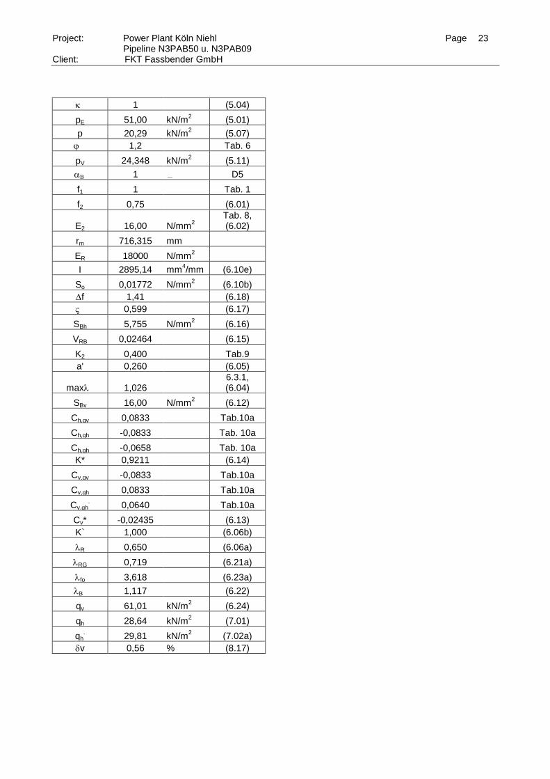
1 (5.04)
pE 51,00 kN/m2 (5.01)
p 20,29 kN/m2 (5.07)
j 1,2 Tab. 6
pV 24,348 kN/m2 (5.11)
1 D5
f1 1 Tab. 1
f2 0,75 (6.01)
E2 16,00 N/mm2
Tab. 8, (6.02)
rm 716,315 mm
ER 18000 N/mm2
I 2895,14 mm4/mm (6.10e)
So 0,01772 N/mm2 (6.10b)
f 1,41 (6.18)
0,599 (6.17)
SBh 5,755 N/mm2 (6.16)
VRB 0,02464 (6.15)
K2 0,400 Tab.9
a' 0,260 (6.05)
max 1,026 6.3.1, (6.04)
SBv 16,00 N/mm2 (6.12)
Ch,qv 0,0833 Tab.10a
Ch,qh -0,0833 Tab. 10a
Ch,qh -0,0658 Tab. 10a
K* 0,9211 (6.14)
Cv,qv -0,0833 Tab.10a
Cv,qh 0,0833 Tab.10a
Cv,qh.
0,0640 Tab.10a
Cv* -0,02435 (6.13)
K` 1,000 (6.06b)
R 0,650 (6.06a)
RG 0,719 (6.21a)
fo 3,618 (6.23a)
1,117 (6.22)
qv 61,01 kN/m
2 (6.24)
qh 28,64 kN/m2 (7.01)
qh. 29,81 kN/m
2 (7.02a)
dv 0,56 % (8.17)
Page 24
Project: Power Plant Köln Niehl Page 24 Pipeline N3PAB50 u. N3PAB09
Client: FKT Fassbender GmbH
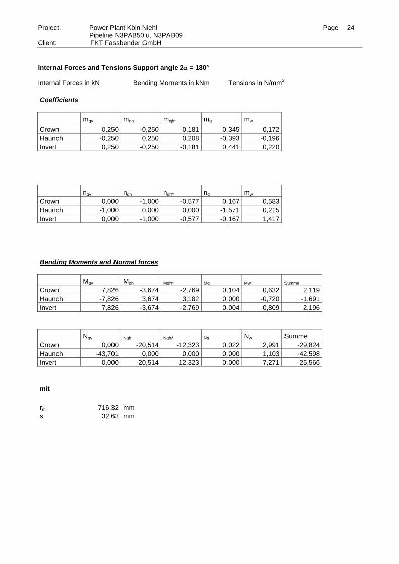
Internal Forces and Tensions Support angle 2 = 180° Internal Forces in kN Bending Moments in kNm Tensions in N/mm
2
Coefficients
mqv mqh mqh* mg mw
Crown 0,250 -0,250 -0,181 0,345 0,172 Haunch -0,250 0,250 0,208 -0,393 -0,196 Invert 0,250 -0,250 -0,181 0,441 0,220
nqv nqh nqh* ng mw
Crown 0,000 -1,000 -0,577 0,167 0,583 Haunch -1,000 0,000 0,000 -1,571 0,215 Invert 0,000 -1,000 -0,577 -0,167 1,417
Bending Moments and Normal forces
Mqv Mqh Mqh* Mg Mw Summe
Crown 7,826 -3,674 -2,769 0,104 0,632 2,119
Haunch -7,826 3,674 3,182 0,000 -0,720 -1,691
Invert 7,826 -3,674 -2,769 0,004 0,809 2,196
Nqv Nqh Nqh* Ng Nw Summe
Crown 0,000 -20,514 -12,323 0,022 2,991 -29,824
Haunch -43,701 0,000 0,000 0,000 1,103 -42,598
Invert 0,000 -20,514 -12,323 0,000 7,271 -25,566
mit
rm 716,32 mm s 32,63 mm
Page 25
Project: Power Plant Köln Niehl Page 25 Pipeline N3PAB50 u. N3PAB09
Client: FKT Fassbender GmbH
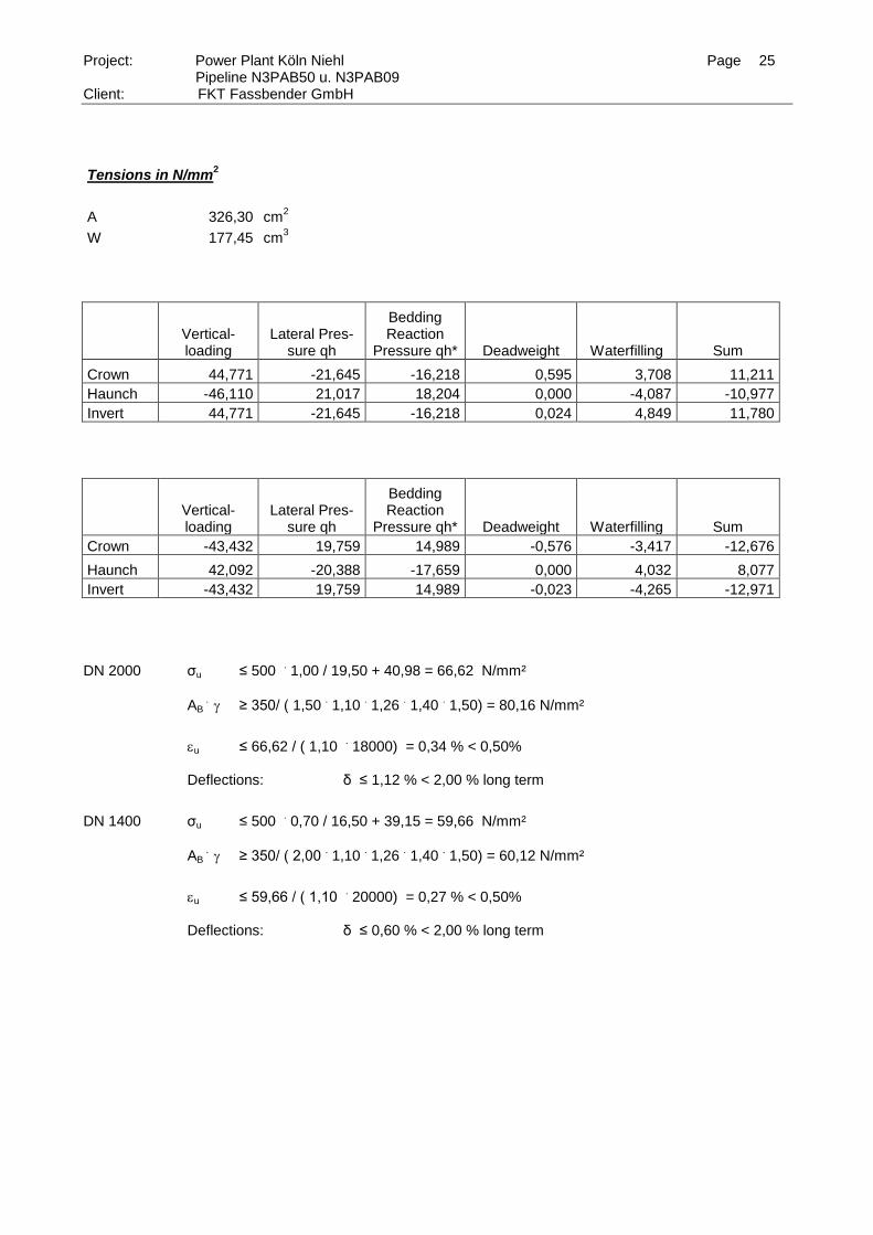
Tensions in N/mm2
A 326,30 cm2
W 177,45 cm3
Vertical- loading
Lateral Pres-sure qh
Bedding Reaction
Pressure qh* Deadweight Waterfilling Sum
Crown 44,771 -21,645 -16,218 0,595 3,708 11,211
Haunch -46,110 21,017 18,204 0,000 -4,087 -10,977
Invert 44,771 -21,645 -16,218 0,024 4,849 11,780
Vertical- loading
Lateral Pres-sure qh
Bedding Reaction
Pressure qh* Deadweight Waterfilling Sum
Crown -43,432 19,759 14,989 -0,576 -3,417 -12,676
Haunch 42,092 -20,388 -17,659 0,000 4,032 8,077
Invert -43,432 19,759 14,989 -0,023 -4,265 -12,971
DN 2000 σu ≤ 500 . 1,00 / 19,50 + 40,98 = 66,62 N/mm²
AB . ≥ 350/ ( 1,50
. 1,10
. 1,26
. 1,40
. 1,50) = 80,16 N/mm²
u ≤ 66,62 / ( 1,10 . 18000) = 0,34 % < 0,50%
Deflections: δ ≤ 1,12 % < 2,00 % long term
DN 1400 σu ≤ 500 . 0,70 / 16,50 + 39,15 = 59,66 N/mm²
AB . ≥ 350/ ( 2,00
. 1,10
. 1,26
. 1,40
. 1,50) = 60,12 N/mm²
u ≤ 59,66 / ( 1,10 . 20000) = 0,27 % < 0,50%
Deflections: δ ≤ 0,60 % < 2,00 % long term
Page 26
Project: Power Plant Köln Niehl Page 26 Pipeline N3PAB50 u. N3PAB09
Client: FKT Fassbender GmbH
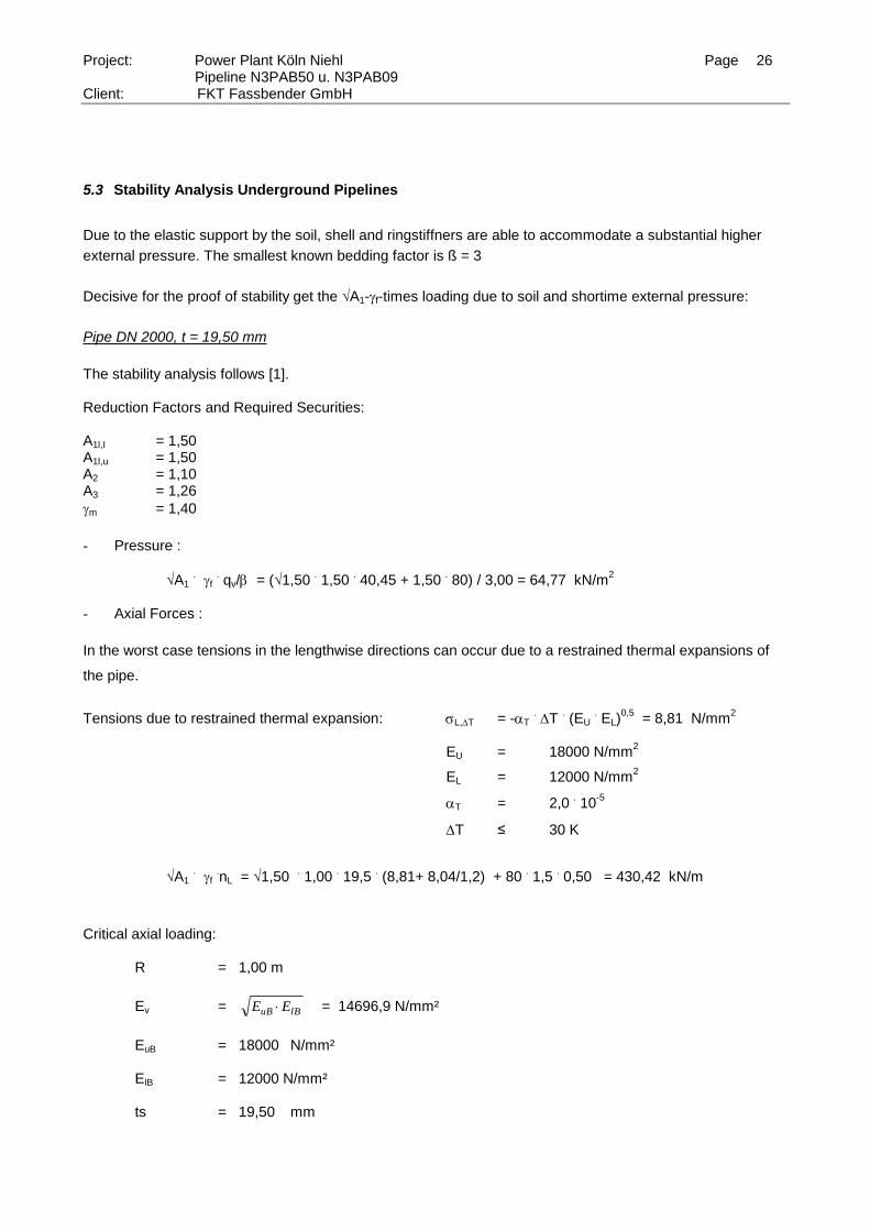
5.3 Stability Analysis Underground Pipelines
Due to the elastic support by the soil, shell and ringstiffners are able to accommodate a substantial higher
external pressure. The smallest known bedding factor is ß = 3
Decisive for the proof of stability get the √A1-f-times loading due to soil and shortime external pressure:
Pipe DN 2000, t = 19,50 mm
The stability analysis follows [1]. Reduction Factors and Required Securities: A1l,I = 1,50 A1l,u = 1,50 A2 = 1,10 A3 = 1,26
m = 1,40
- Pressure :
√A1 . f
. qv/b = (√1,50
. 1,50
. 40,45 + 1,50
. 80) / 3,00 = 64,77 kN/m
2
- Axial Forces :
In the worst case tensions in the lengthwise directions can occur due to a restrained thermal expansions of
the pipe.
Tensions due to restrained thermal expansion: L,T = -T . T
. (EU
. EL)
0,5 = 8,81 N/mm
2
EU = 18000 N/mm2
EL = 12000 N/mm2
T = 2,0 . 10
-5
T ≤ 30 K
√A1
. f
.nL = √1,50
. 1,00
. 19,5
. (8,81+ 8,04/1,2) + 80
. 1,5
. 0,50 = 430,42 kN/m
Critical axial loading: R = 1,00 m
Ev = lBuB EE
= 14696,9 N/mm²
EuB = 18000 N/mm² ElB = 12000 N/mm² ts = 19,50 mm
Page 27
Project: Power Plant Köln Niehl Page 27 Pipeline N3PAB50 u. N3PAB09
Client: FKT Fassbender GmbH
n k E Et
Rk E
t
Rkrit i uB lB
si V
s 2 2
kk
R
t
ir
Z i
1100 ,
ki = 0,34 nkrit = 1903,78 kN/m Critical circumferentiel loading:
5.2
4 385.0
R
t
l
REEp s
o
lBuBkrit
lo = 4000 mm pkrit = 183,52 kN/m² Stability analysis :
n
n
vorh
krit
= 430,42 . 1,1
. 1,26
. 1,40/1903,78 = 0,439 < 1
p
p
vorh
krit
= 64,77 . 1,1
. 1,26
. 1,40/183,52 = 0,68 < 1
( ) ( ). .n
n
p
p
vorh
krit
vorh
krit
125 125 = 0,439
1.25 + 0,68
1.25 = 0,975,00 1
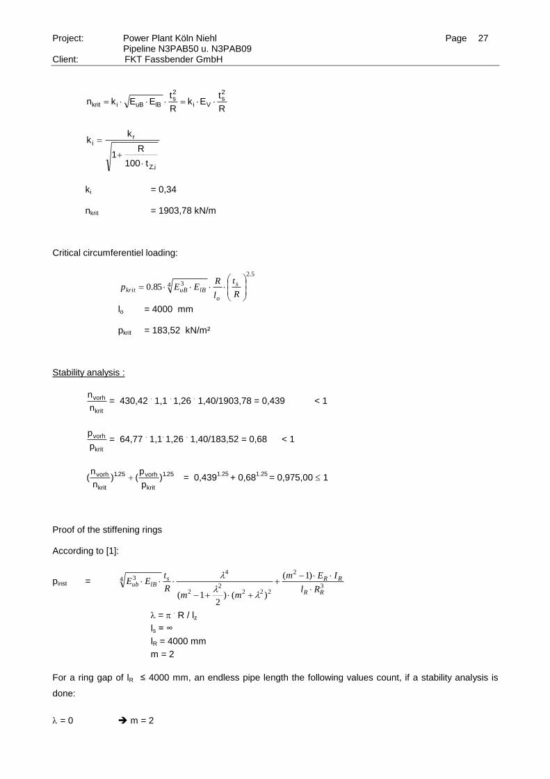
Proof of the stiffening rings According to [1]:
pinst = 3
2
2222
2
44 3 )1(
)()2
1( RR
RRslBub
Rl
IEm
mmR
tEE
= . R / lz
ls = ∞
lR = 4000 mm
m = 2
For a ring gap of lR ≤ 4000 mm, an endless pipe length the following values count, if a stability analysis is
done:
= 0 m = 2
Page 28
Project: Power Plant Köln Niehl Page 28 Pipeline N3PAB50 u. N3PAB09
Client: FKT Fassbender GmbH
Erf ER
. IR ≥ 183,71 kNm²
erf IR ≥ 1837,1 cm4
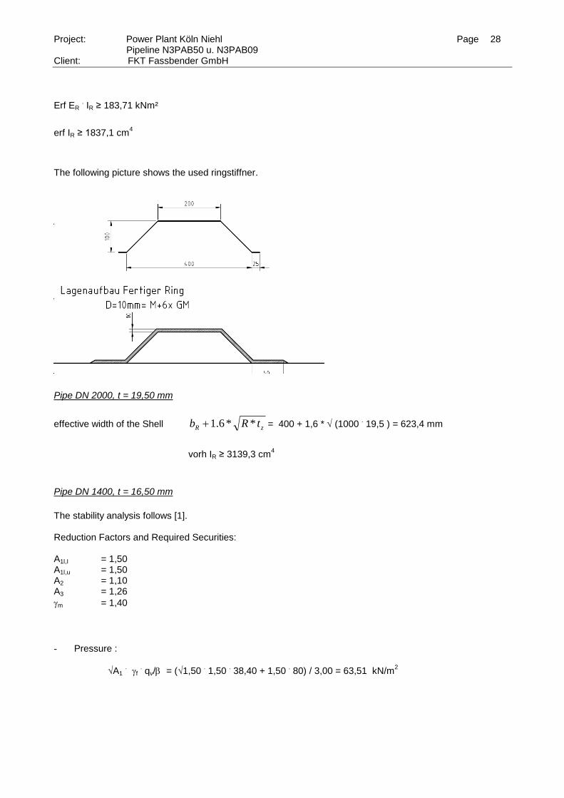
The following picture shows the used ringstiffner.
Pipe DN 2000, t = 19,50 mm
effective width of the Shell zR tRb **6.1 = 400 + 1,6 * (1000 . 19,5 ) = 623,4 mm
vorh IR ≥ 3139,3 cm4
Pipe DN 1400, t = 16,50 mm
The stability analysis follows [1]. Reduction Factors and Required Securities: A1l,I = 1,50 A1l,u = 1,50 A2 = 1,10 A3 = 1,26
m = 1,40
- Pressure :
√A1 . f
. qv/b = (√1,50
. 1,50
. 38,40 + 1,50
. 80) / 3,00 = 63,51 kN/m
2
Page 29
Project: Power Plant Köln Niehl Page 29 Pipeline N3PAB50 u. N3PAB09
Client: FKT Fassbender GmbH
- Axial Forces :
In the worst case tensions in the lengthwise directions can occur due to a restrained thermal expansions of
the pipe.
Tensions due to restrained thermal expansion: L,T = -T . T
. (EU
. EL)
0,5 = 8,81 N/mm
2
EU = 18000 N/mm2
EL = 12000 N/mm2
T = 2,0 . 10
-5
T ≤ 30 K
√A1
. f
.nL = √1,50
. 1,00
. 16,5
. (8,81+ 7,34/1,2) + 80
. 1,5
. 0,35 = 343,64 kN/m
Critical axial loading: R = 0,70 m
Ev = lBuB EE
= 14696,9 N/mm²
EuB = 18000 N/mm² ElB = 12000 N/mm² ts = 16,50 mm
n k E Et
Rk E
t
Rkrit i uB lB
si V
s 2 2
kk
R
t
ir
Z i
1100 ,
ki = 0,35 nkrit = 2006,87 kN/m Critical circumferentiel loading:
5.2
4 385.0
R
t
l
REEp s
o
lBuBkrit
lo = 4000 mm pkrit = 275,18 kN/m²
Page 30
Project: Power Plant Köln Niehl Page 30 Pipeline N3PAB50 u. N3PAB09
Client: FKT Fassbender GmbH
Stability analysis :
n
n
vorh
krit
= 343,64 . 1,1
. 1,26
. 1,40/2006,87 = 0,33 < 1
p
p
vorh
krit
= 63,51 . 1,1
. 1,26
. 1,40/183,52 = 0,60 < 1
( ) ( ). .n
n
p
p
vorh
krit
vorh
krit
125 125 = 0,33
1.25 + 0,60
1.25 = 0,78 1
Proof of the stiffening rings According to [1]:
pinst = 3
2
2222
2
44 3 )1(
)()2
1( RR
RRslBub
Rl
IEm
mmR
tEE
= . R / lz
ls = ∞
lR = 4000 mm
m = 2
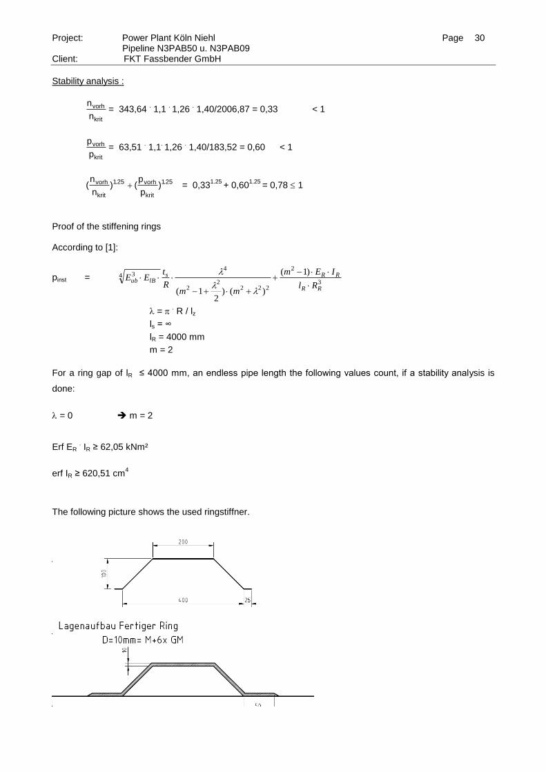
For a ring gap of lR ≤ 4000 mm, an endless pipe length the following values count, if a stability analysis is
done:
= 0 m = 2 Erf ER
. IR ≥ 62,05 kNm²
erf IR ≥ 620,51 cm4
The following picture shows the used ringstiffner.
Page 31
Project: Power Plant Köln Niehl Page 31 Pipeline N3PAB50 u. N3PAB09
Client: FKT Fassbender GmbH
effective width of the Shell zR tRb **6.1 = 440 + 1,6 * (700 . 16,5 ) = 572,0 mm
vorh IR ≥2757,7 cm
4
ters =(12 . IR /lR )
1/ 3 . 0,75 = (12
. 2757,7/400)
1/ 3 . 0,75
. 10 = 32,63 mm
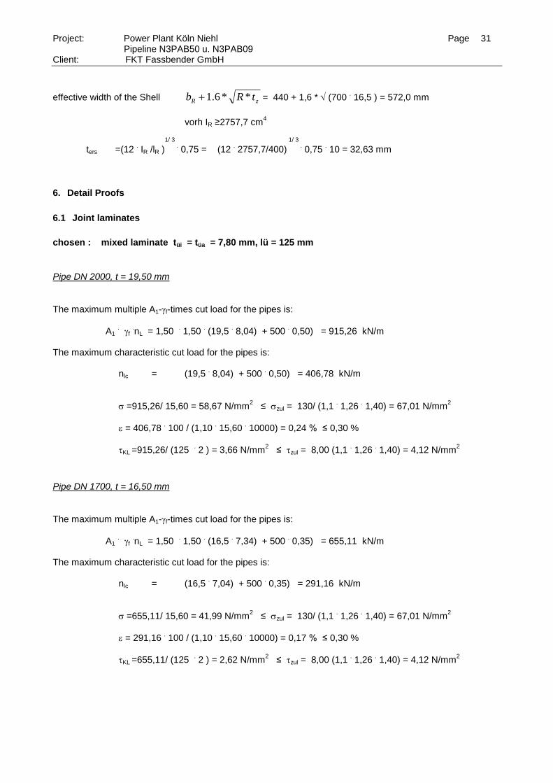
6. Detail Proofs
6.1 Joint laminates
chosen : mixed laminate tüi = tüa = 7,80 mm, lü = 125 mm
Pipe DN 2000, t = 19,50 mm
The maximum multiple A1-f-times cut load for the pipes is:
A1 . f
.nL = 1,50
. 1,50
. (19,5
. 8,04) + 500
. 0,50) = 915,26 kN/m
The maximum characteristic cut load for the pipes is: nlc = (19,5
. 8,04) + 500
. 0,50) = 406,78 kN/m
=915,26/ 15,60 = 58,67 N/mm2 ≤ zul = 130/ (1,1
. 1,26
. 1,40) = 67,01 N/mm
2
= 406,78 . 100 / (1,10
. 15,60
. 10000) = 0,24 % ≤ 0,30 %
KL =915,26/ (125 . 2 ) = 3,66 N/mm
2 ≤ zul = 8,00 (1,1
. 1,26
. 1,40) = 4,12 N/mm
2
Pipe DN 1700, t = 16,50 mm
The maximum multiple A1-f-times cut load for the pipes is:
A1 . f
.nL = 1,50
. 1,50
. (16,5
. 7,34) + 500
. 0,35) = 655,11 kN/m
The maximum characteristic cut load for the pipes is: nlc = (16,5
. 7,04) + 500
. 0,35) = 291,16 kN/m
=655,11/ 15,60 = 41,99 N/mm2 ≤ zul = 130/ (1,1
. 1,26
. 1,40) = 67,01 N/mm
2
= 291,16 . 100 / (1,10
. 15,60
. 10000) = 0,17 % ≤ 0,30 %
KL =655,11/ (125 . 2 ) = 2,62 N/mm
2 ≤ zul = 8,00 (1,1
. 1,26
. 1,40) = 4,12 N/mm
2
Page 32
Project: Power Plant Köln Niehl Page 32 Pipeline N3PAB50 u. N3PAB09
Client: FKT Fassbender GmbH
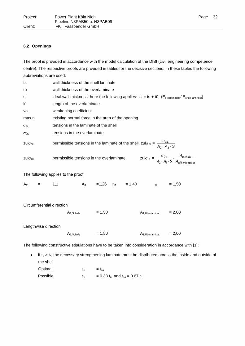
6.2 Openings
The proof is provided in accordance with the model calculation of the DIBt (civil engineering competence
centre). The respective proofs are provided in tables for the decisive sections. In these tables the following
abbreviations are used:
ts wall thickness of the shell laminate
tü wall thickness of the overlaminate
si ideal wall thickness; here the following applies: si = ts + tü . (Eoverlaminate/ Eshell laminate)
lü length of the overlaminate
va weakening coefficient
max n existing normal force in the area of the opening
SL tensions in the laminate of the shell
ÜL tensions in the overlaminate
zulSL permissible tensions in the laminate of the shell, zulSL = SAA
SL
32
zulÜL permissible tensions in the overlaminate, zulÜL = atÜberla
SchaleÜL
A
A
SAA min1
1
32
The following applies to the proof:
A2 = 1,1 A3 =1,26 M = 1,40 f = 1,50
Circumferential direction
A1,Schale = 1,50 A1,Überlaminat = 2,00
Lengthwise direction
A1,Schale = 1,50 A1,Überlaminat = 2,00
The following constructive stipulations have to be taken into consideration in accordance with [1]:
If tü > ts, the necessary strengthening laminate must be distributed across the inside and outside of
the shell.
Optimal: tüi = tüa
Possible: tüi = 0.33 tü and tüa = 0.67 tü
Page 33
Project: Power Plant Köln Niehl Page 33 Pipeline N3PAB50 u. N3PAB09
Client: FKT Fassbender GmbH
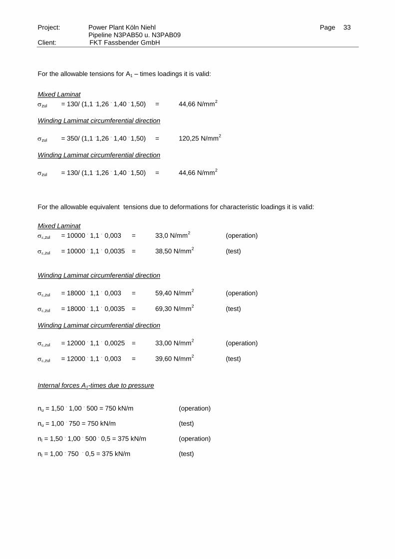
For the allowable tensions for A1 – times loadings it is valid:
Mixed Laminat
zul = 130/ (1,1 .1,26
. 1,40
. 1,50) = 44,66 N/mm
2
Winding Lamimat circumferential direction
zul = 350/ (1,1 .1,26
. 1,40
. 1,50) = 120,25 N/mm
2
Winding Lamimat circumferential direction
zul = 130/ (1,1 .1,26
. 1,40
. 1,50) = 44,66 N/mm
2
For the allowable equivalent tensions due to deformations for characteristic loadings it is valid:
Mixed Laminat
,zul = 10000 . 1,1
. 0,003 = 33,0 N/mm
2 (operation)
,zul = 10000 . 1,1
. 0,0035 = 38,50 N/mm
2 (test)
Winding Lamimat circumferential direction
,zul = 18000 . 1,1
. 0,003 = 59,40 N/mm
2 (operation)
,zul = 18000 . 1,1
. 0,0035 = 69,30 N/mm
2 (test)
Winding Lamimat circumferential direction
,zul = 12000 . 1,1
. 0,0025 = 33,00 N/mm
2 (operation)
,zul = 12000 . 1,1
. 0,003 = 39,60 N/mm
2 (test)
Internal forces A1-times due to pressure
nu = 1,50 . 1,00
. 500 = 750 kN/m (operation)
nu = 1,00
. 750 = 750 kN/m (test)
nl = 1,50 . 1,00
. 500
. 0,5 = 375 kN/m (operation)
nl = 1,00
. 750
. 0,5 = 375 kN/m (test)
Page 34
Project: Power Plant Köln Niehl Page 34 Pipeline N3PAB50 u. N3PAB09
Client: FKT Fassbender GmbH
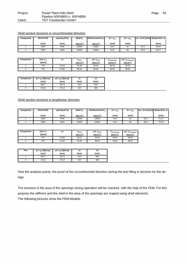
Shell section tensions in circumferential direction
Component Shell Ø DN opening Ø da Shell Eu Reinforcement Eu ts = szyl tü = sUE sa = ts+tü [mm] idealy thick. si
[mm] [mm] [N/mm
2] [N/mm
2] [mm] [mm] [mm]
1 2000 1400 18000 10000 19,5 62 81,5 53,94
2 2000 1620 18000 10000 19,5 66 85,5 56,17
Component max nud va Shell zul.Shell Jointlaminat zul.Jointaminat
[kN/m] [N/mm2] [N/mm
2] [N/mm
2] [N/mm
2]
1 750 0,213 65,30 69,30 36,28 38,50
2 750 0,195 68,44 69,30 38,02 38,50
Component erf. x1(Da*sa) erf. x2(da*sa) x1 x2
[mm] [mm] [mm] [mm]
1 403,7 337,8 410 350
2 413,5 372,2 420 380
Shell section tensions in lengthwise direction
Component Shell Ø DN opening Ø da Shell Eu Reinforcement Eu ts = szyl tü = sUE sa = ts+tü [mm] idealy thick. si
[mm] [mm] [N/mm
2] [N/mm
2] [mm] [mm] [mm]
1 2000 1400 12000 10000 19,5 62 81,5 71,17
2 2000 1620 12000 10000 19,5 66 85,5 74,50
Component max nld va Shell zul.Shell Jointlaminat zul.Jointaminat
[kN/m] [N/mm2] [N/mm
2] [N/mm
2] [N/mm
2]
1 375 0,233 22,57 39,60 18,81 38,50
2 375 0,215 23,39 39,60 19,50 38,50
Pos erf. x1(Da*sa) erf. x2(da*sa) x1 x2
[mm] [mm] [mm] [mm]
1 403,7 337,8 410 350
2 413,5 372,2 420 380
How the analysis points, the proof of the circumferential direction during the test filling is decisive for the de-
sign.
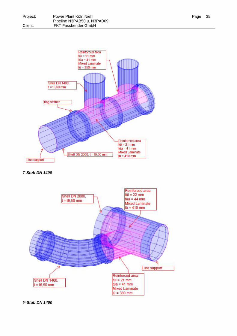
The tensions in the area of the openings during operation will be checked with the help of the FEM. For this
purpose the stiffners and the shell in the area of the openings are maped using shell elements.
The following pictures show the FEM-Models.
Page 35
Project: Power Plant Köln Niehl Page 35 Pipeline N3PAB50 u. N3PAB09
Client: FKT Fassbender GmbH
T-Stub DN 1400
Y-Stub DN 1400
Page 36
Project: Power Plant Köln Niehl Page 36 Pipeline N3PAB50 u. N3PAB09
Client: FKT Fassbender GmbH
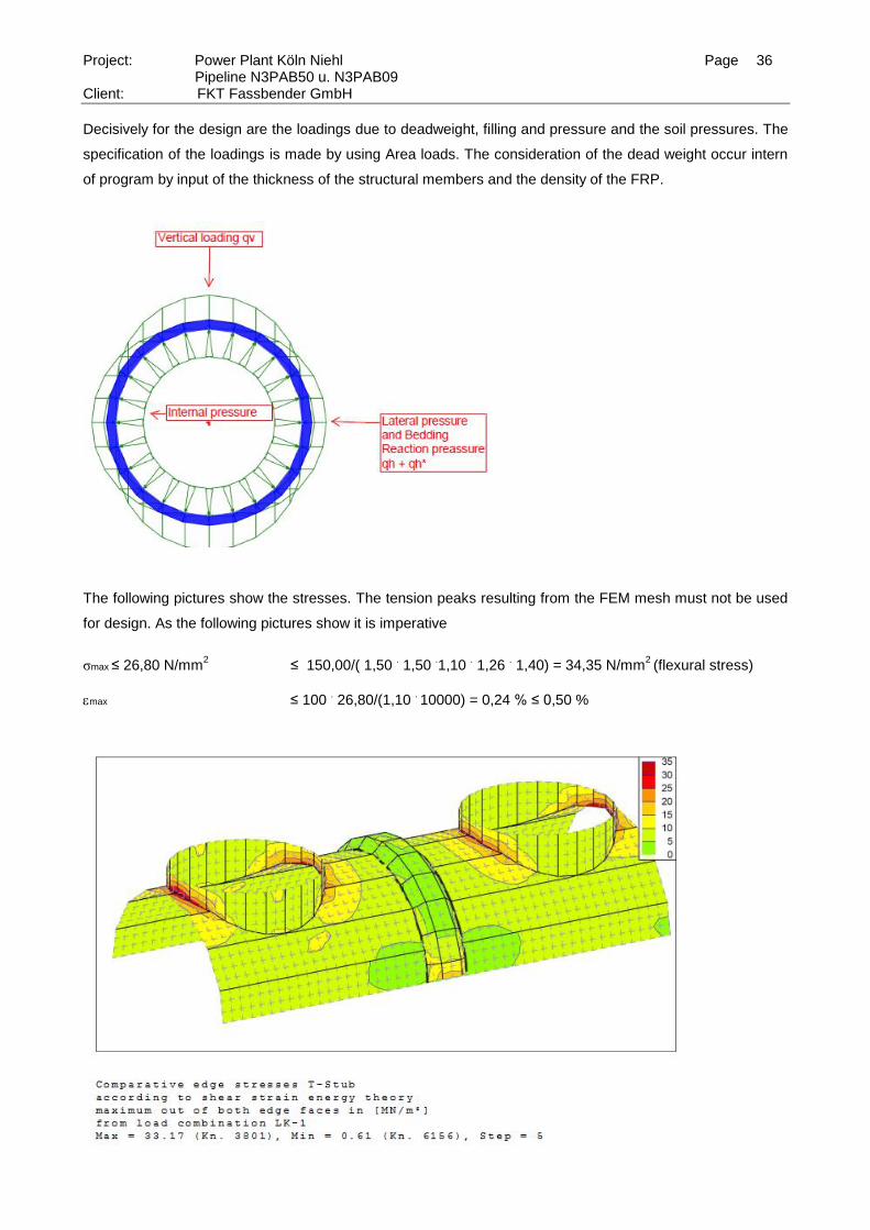
Decisively for the design are the loadings due to deadweight, filling and pressure and the soil pressures. The
specification of the loadings is made by using Area loads. The consideration of the dead weight occur intern
of program by input of the thickness of the structural members and the density of the FRP.
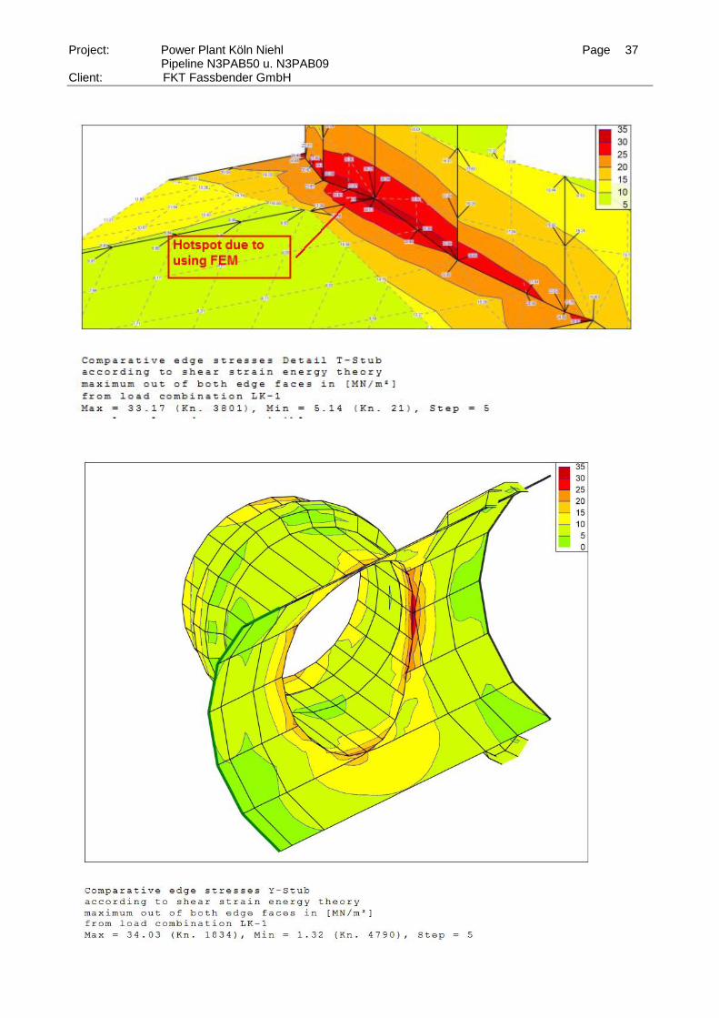
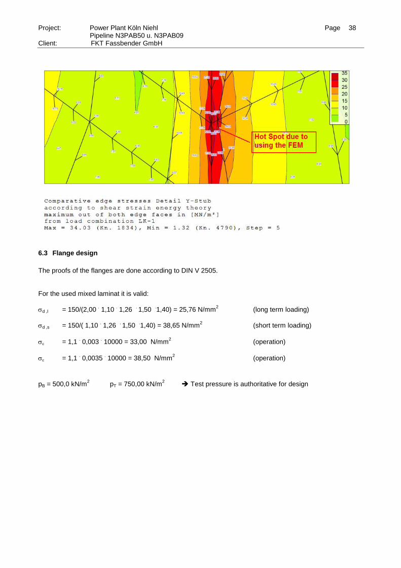
The following pictures show the stresses. The tension peaks resulting from the FEM mesh must not be used
for design. As the following pictures show it is imperative
σmax ≤ 26,80 N/mm
2 ≤ 150,00/( 1,50
. 1,50
.1,10
. 1,26
. 1,40) = 34,35 N/mm
2 (flexural stress)
max ≤ 100 . 26,80/(1,10
. 10000) = 0,24 % ≤ 0,50 %
Page 37
Project: Power Plant Köln Niehl Page 37 Pipeline N3PAB50 u. N3PAB09
Client: FKT Fassbender GmbH
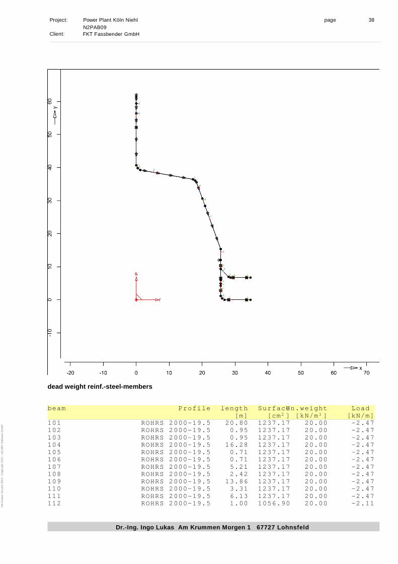
Page 38
Project: Power Plant Köln Niehl Page 38 Pipeline N3PAB50 u. N3PAB09
Client: FKT Fassbender GmbH
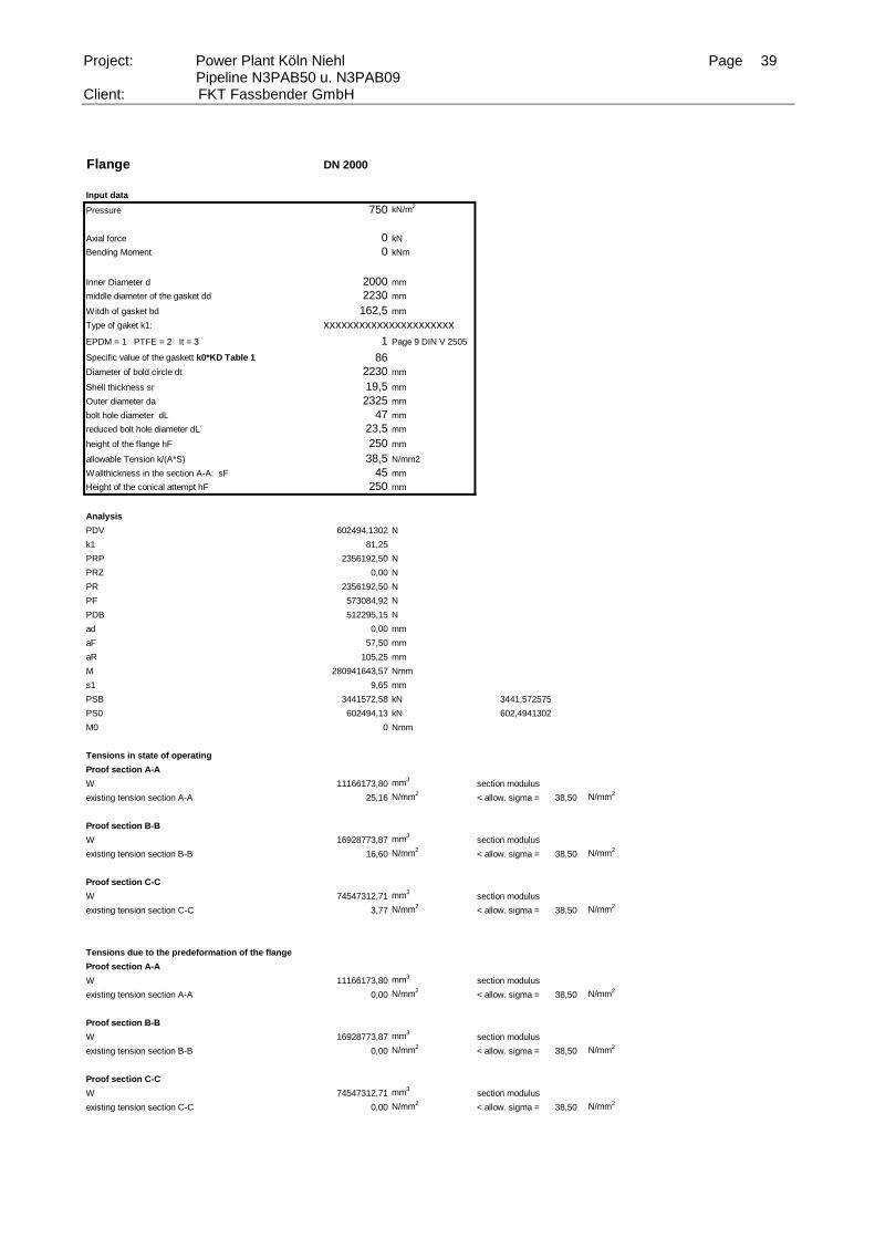
6.3 Flange design
The proofs of the flanges are done according to DIN V 2505. For the used mixed laminat it is valid:
d ,l = 150/(2,00 . 1,10
. 1,26
. 1,50
.1,40) = 25,76 N/mm
2 (long term loading)
d ,s = 150/( 1,10 . 1,26
. 1,50
.1,40) = 38,65 N/mm
2 (short term loading)
= 1,1 . 0,003
. 10000 = 33,00 N/mm
2 (operation)
= 1,1 . 0,0035
. 10000 = 38,50 N/mm
2 (operation)
pB = 500,0 kN/m2
pT = 750,00 kN/m2 Test pressure is authoritative for design
Page 39
Project: Power Plant Köln Niehl Page 39 Pipeline N3PAB50 u. N3PAB09
Client: FKT Fassbender GmbH
Flange DN 2000
Input data
Pressure 750 kN/m2
Axial force 0 kN
Bending Moment 0 kNm
Inner Diameter d 2000 mm
middle diameter of the gasket dd 2230 mm 2182
Witdh of gasket bd 162,5 mm
Type of gaket k1: xxxxxxxxxxxxxxxxxxxxxx
EPDM = 1 PTFE = 2 It = 3 1 Page 9 DIN V 2505
Specific value of the gaskett k0*KD Table 1 86
Diameter of bold circle dt 2230 mm
Shell thickness sr 19,5 mm
Outer diameter da 2325 mm
bolt hole diameter dL 47 mm
reduced bolt hole diameter dL´ 23,5 mm
height of the flange hF 250 mm
allowable Tension k/(A*S) 38,5 N/mm2
Wallthickness in the section A-A: sF 45 mm
Height of the conical attempt hF 250 mm
Analysis
PDV 602494,1302 N
k1 81,25
PRP 2356192,50 N
PRZ 0,00 N
PR 2356192,50 N
PF 573084,92 N
PDB 512295,15 N
ad 0,00 mm
aF 57,50 mm
aR 105,25 mm
M 280941643,57 Nmm
s1 9,65 mm
PSB 3441572,58 kN 3441,572575 0,18
PS0 602494,13 kN 602,4941302
M0 0 Nmm
Tensions in state of operating
Proof section A-A
W 11166173,80 mm3
section modulus
existing tension section A-A 25,16 N/mm2
< allow. sigma = 38,50 N/mm2
Proof section B-B
W 16928773,87 mm3
section modulus
existing tension section B-B 16,60 N/mm2
< allow. sigma = 38,50 N/mm2
Proof section C-C
W 74547312,71 mm3
section modulus
existing tension section C-C 3,77 N/mm2
< allow. sigma = 38,50 N/mm2
Tensions due to the predeformation of the flange
Proof section A-A
W 11166173,80 mm3
section modulus
existing tension section A-A 0,00 N/mm2
< allow. sigma = 38,50 N/mm2
Proof section B-B
W 16928773,87 mm3
section modulus
existing tension section B-B 0,00 N/mm2
< allow. sigma = 38,50 N/mm2
Proof section C-C
W 74547312,71 mm3
section modulus
existing tension section C-C 0,00 N/mm2
< allow. sigma = 38,50 N/mm2
Page 40
Project: Power Plant Köln Niehl Page 40 Pipeline N3PAB50 u. N3PAB09
Client: FKT Fassbender GmbH
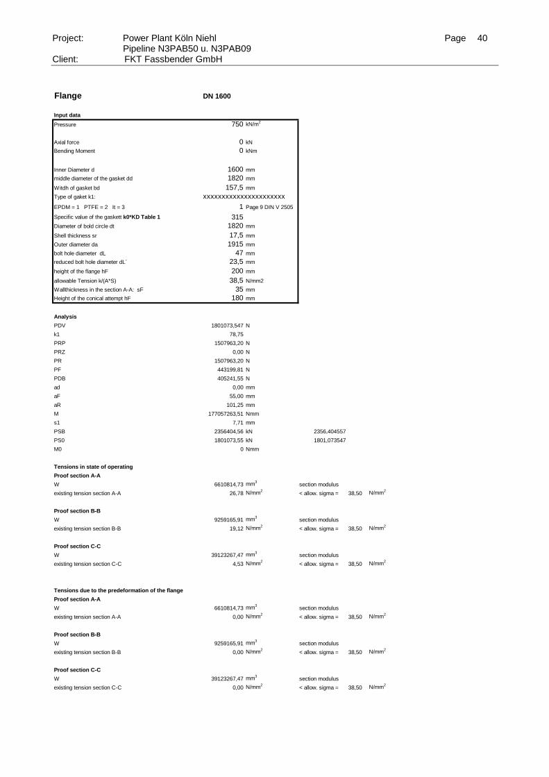
Flange DN 1600
Input data
Pressure 750 kN/m2
Axial force 0 kN
Bending Moment 0 kNm
Inner Diameter d 1600 mm
middle diameter of the gasket dd 1820 mm 1775
Witdh of gasket bd 157,5 mm
Type of gaket k1: xxxxxxxxxxxxxxxxxxxxxx
EPDM = 1 PTFE = 2 It = 3 1 Page 9 DIN V 2505
Specific value of the gaskett k0*KD Table 1 315
Diameter of bold circle dt 1820 mm
Shell thickness sr 17,5 mm
Outer diameter da 1915 mm
bolt hole diameter dL 47 mm
reduced bolt hole diameter dL´ 23,5 mm
height of the flange hF 200 mm
allowable Tension k/(A*S) 38,5 N/mm2
Wallthickness in the section A-A: sF 35 mm
Height of the conical attempt hF 180 mm
Analysis
PDV 1801073,547 N
k1 78,75
PRP 1507963,20 N
PRZ 0,00 N
PR 1507963,20 N
PF 443199,81 N
PDB 405241,55 N
ad 0,00 mm
aF 55,00 mm
aR 101,25 mm
M 177057263,51 Nmm
s1 7,71 mm
PSB 2356404,56 kN 2356,404557 0,76
PS0 1801073,55 kN 1801,073547
M0 0 Nmm
Tensions in state of operating
Proof section A-A
W 6610814,73 mm3
section modulus
existing tension section A-A 26,78 N/mm2
< allow. sigma = 38,50 N/mm2
Proof section B-B
W 9259165,91 mm3
section modulus
existing tension section B-B 19,12 N/mm2
< allow. sigma = 38,50 N/mm2
Proof section C-C
W 39123267,47 mm3
section modulus
existing tension section C-C 4,53 N/mm2
< allow. sigma = 38,50 N/mm2
Tensions due to the predeformation of the flange
Proof section A-A
W 6610814,73 mm3
section modulus
existing tension section A-A 0,00 N/mm2
< allow. sigma = 38,50 N/mm2
Proof section B-B
W 9259165,91 mm3
section modulus
existing tension section B-B 0,00 N/mm2
< allow. sigma = 38,50 N/mm2
Proof section C-C
W 39123267,47 mm3
section modulus
existing tension section C-C 0,00 N/mm2
< allow. sigma = 38,50 N/mm2
Page 41
Project: Power Plant Köln Niehl Page 41 Pipeline N3PAB50 u. N3PAB09
Client: FKT Fassbender GmbH
Flange DN 1400
Input data
Pressure 750 kN/m2
Axial force 0 kN
Bending Moment 0 kNm
Inner Diameter d 1400 mm
middle diameter of the gasket dd 1590 mm 1554
Witdh of gasket bd 137,5 mm
Type of gaket k1: xxxxxxxxxxxxxxxxxxxxxx
EPDM = 1 PTFE = 2 It = 3 1 Page 9 DIN V 2505
Specific value of the gaskett k0*KD Table 1 95
Diameter of bold circle dt 1590 mm
Shell thickness sr 16,5 mm
Outer diameter da 1675 mm
bolt hole diameter dL 37 mm
reduced bolt hole diameter dL´ 18,5 mm
height of the flange hF 180 mm
allowable Tension k/(A*S) 38,5 N/mm2
Wallthickness in the section A-A: sF 30 mm
Height of the conical attempt hF 150 mm
Analysis
PDV 474537,1695 N
k1 68,75
PRP 1154534,33 N
PRZ 0,00 N
PR 1154534,33 N
PF 334638,24 N
PDB 309073,55 N
ad 0,00 mm
aF 47,50 mm
aR 86,75 mm
M 116051169,08 Nmm
s1 6,74 mm
PSB 1798246,12 kN 1798,246116 0,26
PS0 474537,17 kN 474,5371695
M0 0 Nmm
Tensions in state of operating
Proof section A-A
W 4677441,31 mm3
section modulus
existing tension section A-A 24,81 N/mm2
< allow. sigma = 38,50 N/mm2
Proof section B-B
W 6430680,69 mm3
section modulus
existing tension section B-B 18,05 N/mm2
< allow. sigma = 38,50 N/mm2
Proof section C-C
W 27787991,87 mm3
section modulus
existing tension section C-C 4,18 N/mm2
< allow. sigma = 38,50 N/mm2
Tensions due to the predeformation of the flange
Proof section A-A
W 4677441,31 mm3
section modulus
existing tension section A-A 0,00 N/mm2
< allow. sigma = 38,50 N/mm2
Proof section B-B
W 6430680,69 mm3
section modulus
existing tension section B-B 0,00 N/mm2
< allow. sigma = 38,50 N/mm2
Proof section C-C
W 27787991,87 mm3
section modulus
existing tension section C-C 0,00 N/mm2
< allow. sigma = 38,50 N/mm2
Page 42
Project: Power Plant Köln Niehl Page 42 Pipeline N3PAB50 u. N3PAB09
Client: FKT Fassbender GmbH
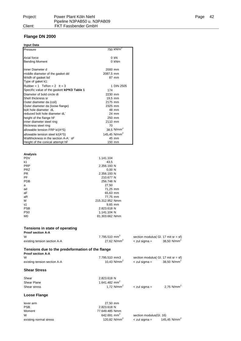
Flange DN 2000
Input Data
Pressure 750 kN/m2
Axial force 0 kN
Bending Moment 0 kNm
Inner Diameter d 2000 mm
middle diameter of the gasket dd 2087,5 mm 2107
Witdh of gasket bd 87 mm
Type of gaket k1:
Rubber = 1 Teflon = 2 It = 3 1 DIN 2505
Specific value of the gaskett k0*KD Table 1 174
Diameter of bold circle dt 2230 mm
Shell thickness sr 19,5 mm
Outer diameter da (coil) 2175 mm
Outer diameter da (loose flange) 2325 mm
bolt hole diameter dL 48 mm
reduced bolt hole diameter dL´ 24 mm
height of the flange hF 250 mm
inner diameter steel ring 2110 mm
thickness steel ring 70
allowable tension FRP k/(A*S) 38,5 N/mm2
allowable tension steel k/(A*S) 145,45 N/mm2
Wallthickness in the section A-A: sF 45 mm
Height of the conical attempt hF 150 mm
Analysis
PDV 1.141.104
k1 43,5
PRP 2.356.193 N
PRZ 0,00 N
PR 2.356.193 N
PF 210.677 N
PDB 256.748 N
a 27,50
ad 71,25 mm
aF 65,63 mm
aR 77,75 mm
M 215.312.952 Nmm
s1 9,65 mm
PSB 2.823.618 N
PS0 1.141.104 N
M0 81.303.662 Nmm
Tensions in state of operating Proof section A-A
W 7.795.510 mm3
section modulus( Gl. 17 mit sr = sf)
existing tension section A-A 27,62 N/mm2
< zul sigma = 38,50 N/mm2
Tensions due to the predeformation of the flangeProof section A-A
W 7.795.510 mm3 section modulus( Gl. 17 mit sr = sf)
existing tension section A-A 10,43 N/mm2
< zul sigma = 38,50 N/mm2
Shear Stress
Shear 2.823.618 N
Shear Plane 1.641.482 mm2
Shear stress 1,72 N/mm2
< zul sigma = 2,75 N/mm2
Loose Flange
lever arm 27,50 mm
PSB 2.823.618 N
Moment 77.649.485 Nmm
W 642.691 mm3
section modulus(Gl. 16)
existing normal stress 120,82 N/mm2
< zul sigma = 145,45 N/mm2
Page 43
Project: Power Plant Köln Niehl Page 43 Pipeline N3PAB50 u. N3PAB09
Client: FKT Fassbender GmbH
Flange DN 1600
Input Data
Pressure 750 kN/m2
Axial force 0 kN
Bending Moment 0 kNm
Inner Diameter d 1600 mm
middle diameter of the gasket dd 1680 mm 1696,5
Witdh of gasket bd 80 mm
Type of gaket k1:
Rubber = 1 Teflon = 2 It = 3 1 DIN 2505
Specific value of the gaskett k0*KD Table 1 160
Diameter of bold circle dt 1820 mm
Shell thickness sr 16,5 mm
Outer diameter da (coil) 1760 mm
Outer diameter da (loose flange) 1915 mm
bolt hole diameter dL 48 mm
reduced bolt hole diameter dL´ 24 mm
height of the flange hF 200 mm
inner diameter steel ring 1671 mm
thickness steel ring 60
allowable tension FRP k/(A*S) 38,5 N/mm2
allowable tension steel k/(A*S) 145,45 N/mm2
Wallthickness in the section A-A: sF 30 mm
Height of the conical attempt hF 150 mm
Analysis
PDV 844.459
k1 40
PRP 1.507.963 N
PRZ 0,00 N
PR 1.507.963 N
PF 154.566 N
PDB 190.003 N
a 30,00
ad 70,00 mm
aF 60,00 mm
aR 71,75 mm
M 130.770.569 Nmm
s1 7,71 mm
PSB 1.852.533 N
PS0 844.459 N
M0 59.112.157 Nmm
Tensions in state of operating Proof section A-A
W 4.068.379 mm3
section modulus( Gl. 17 mit sr = sf)
existing tension section A-A 32,14 N/mm2
< zul sigma = 38,50 N/mm2
Tensions due to the predeformation of the flangeProof section A-A
W 4.068.379 mm3 section modulus( Gl. 17 mit sr = sf)
existing tension section A-A 14,53 N/mm2
< zul sigma = 38,50 N/mm2
Shear Stress
Shear 1.852.533 N
Shear Plane 1.043.009 mm2
Shear stress 1,78 N/mm2
< zul sigma = 2,75 N/mm2
Loose Flange
lever arm 30,00 mm
PSB 1.852.533 N
Moment 55.575.984 Nmm
W 554.177 mm3
section modulus(Gl. 16)
existing normal stress 100,29 N/mm2
< zul sigma = 145,45 N/mm2
Page 44
Project: Power Plant Köln Niehl Page 44 Pipeline N3PAB50 u. N3PAB09
Client: FKT Fassbender GmbH
Flange DN 1400
Input Data
Pressure 750 kN/m2
Axial force 0 kN
Bending Moment 20 kNm
Inner Diameter d 1400 mm
middle diameter of the gasket dd 1467,5 mm 1484
Witdh of gasket bd 67,5 mm
Type of gaket k1:
Rubber = 1 Teflon = 2 It = 3 1 DIN 2505
Specific value of the gaskett k0*KD Table 1 75
Diameter of bold circle dt 1590 mm
Shell thickness sr 16,5 mm
Outer diameter da (coil) 1535 mm
Outer diameter da (loose flange) 1675 mm
bolt hole diameter dL 42 mm
reduced bolt hole diameter dL´ 21 mm
height of the flange hF 180 mm
inner diameter steel ring 1460 mm
thickness steel ring 55
allowable tension FRP k/(A*S) 38,5 N/mm2
allowable tension steel k/(A*S) 145,45 N/mm2
Wallthickness in the section A-A: sF 28,5 mm
Height of the conical attempt hF 150 mm
Analysis
PDV 345.771
k1 33,75
PRP 1.154.534 N
PRZ 57142,86 N
PR 1.211.677 N
PF 114.014 N
PDB 140.037 N
a 27,50
ad 61,25 mm
aF 50,63 mm
aR 59,25 mm
M 86.141.117 Nmm
s1 7,07 mm
PSB 1.465.728 N
PS0 402.914 N
M0 24.678.489 Nmm
Tensions in state of operating Proof section A-A
W 2.860.339 mm3
section modulus( Gl. 17 mit sr = sf)
existing tension section A-A 30,12 N/mm2
< zul sigma = 38,50 N/mm2
Tensions due to the predeformation of the flangeProof section A-A
W 2.860.339 mm3 section modulus( Gl. 17 mit sr = sf)
existing tension section A-A 8,63 N/mm2
< zul sigma = 38,50 N/mm2
Shear Stress
Shear 1.465.728 N
Shear Plane 823.914 mm2
Shear stress 1,78 N/mm2
< zul sigma = 2,75 N/mm2
Loose Flange
lever arm 27,50 mm
PSB 1.465.728 N
Moment 40.307.533 Nmm
W 411.018 mm3
section modulus(Gl. 16)
existing normal stress 98,07 N/mm2
< zul sigma = 145,45 N/mm2
Page 45
Project: Power Plant Köln Niehl Page 45 Pipeline N3PAB50 u. N3PAB09
Client: FKT Fassbender GmbH
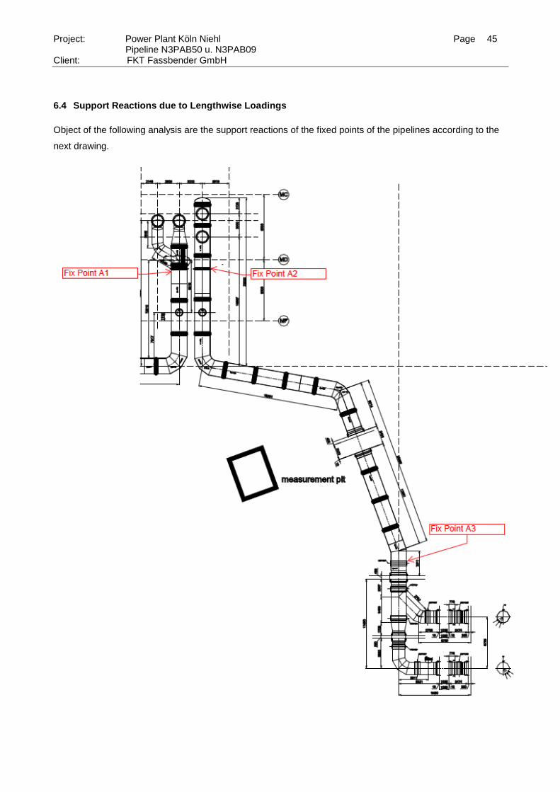
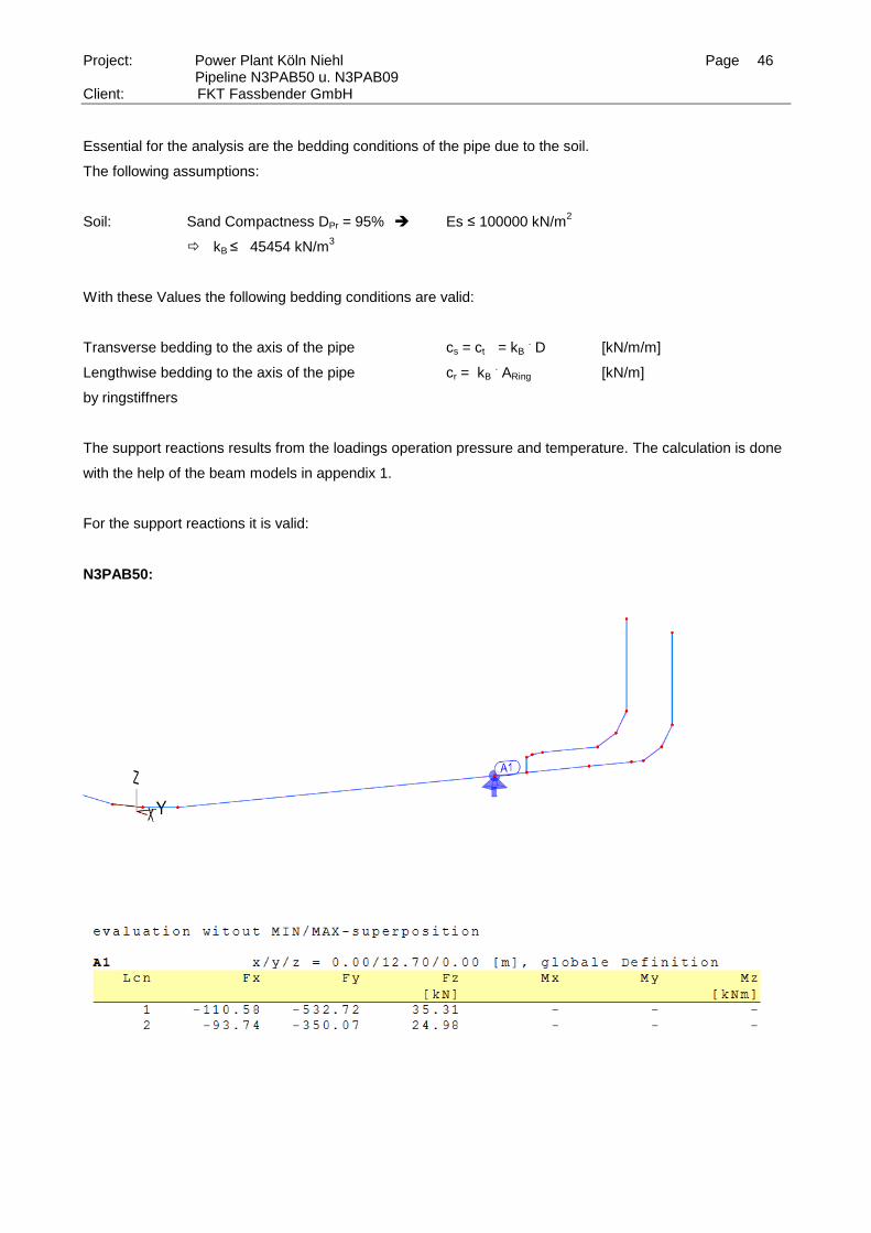
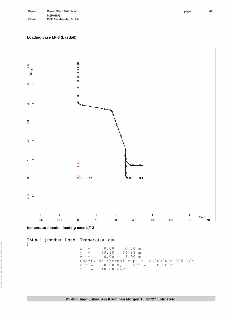
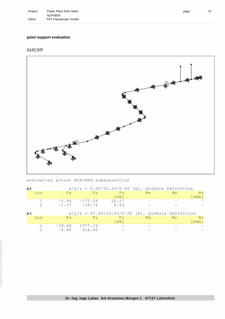
6.4 Support Reactions due to Lengthwise Loadings
Object of the following analysis are the support reactions of the fixed points of the pipelines according to the
next drawing.
Page 46
Project: Power Plant Köln Niehl Page 46 Pipeline N3PAB50 u. N3PAB09
Client: FKT Fassbender GmbH
Essential for the analysis are the bedding conditions of the pipe due to the soil.
The following assumptions:
Soil: Sand Compactness DPr = 95% Es ≤ 100000 kN/m2
kB ≤ 45454 kN/m3
With these Values the following bedding conditions are valid:
Transverse bedding to the axis of the pipe cs = ct = kB . D [kN/m/m]
Lengthwise bedding to the axis of the pipe cr = kB . ARing [kN/m]
by ringstiffners
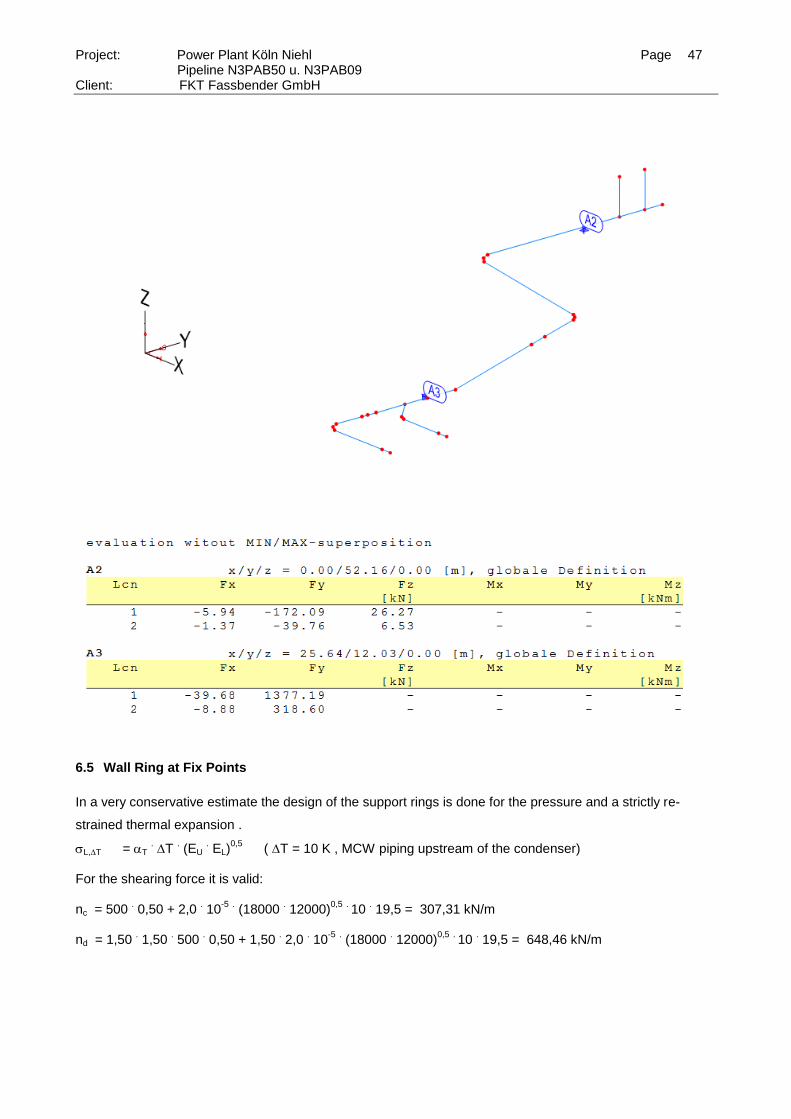
The support reactions results from the loadings operation pressure and temperature. The calculation is done
with the help of the beam models in appendix 1.
For the support reactions it is valid:
N3PAB50:
Page 47
Project: Power Plant Köln Niehl Page 47 Pipeline N3PAB50 u. N3PAB09
Client: FKT Fassbender GmbH
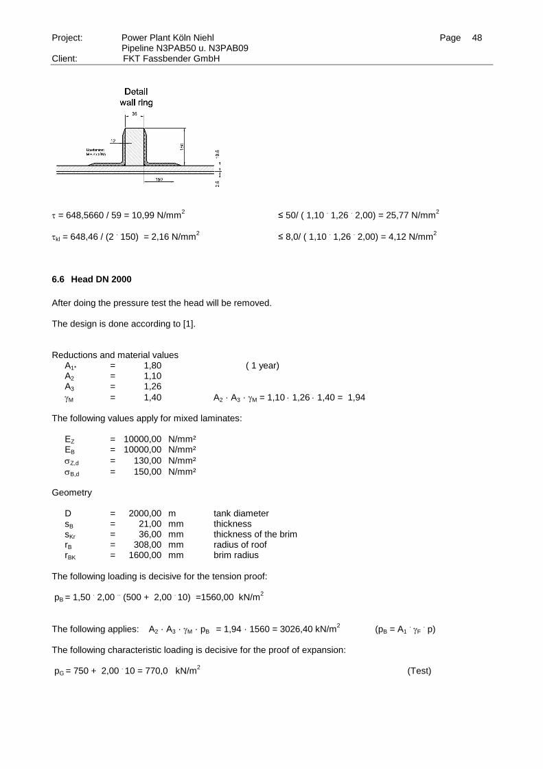
6.5 Wall Ring at Fix Points
In a very conservative estimate the design of the support rings is done for the pressure and a strictly re-
strained thermal expansion .
L,T = T . T
. (EU
. EL)
0,5
( T = 10 K , MCW piping upstream of the condenser)
For the shearing force it is valid: nc = 500
. 0,50 + 2,0
. 10
-5 . (18000
. 12000)
0,5 . 10
. 19,5 = 307,31 kN/m
nd = 1,50
. 1,50
. 500
. 0,50 + 1,50
. 2,0
. 10
-5 . (18000
. 12000)
0,5 . 10
. 19,5 = 648,46 kN/m
Page 48
Project: Power Plant Köln Niehl Page 48 Pipeline N3PAB50 u. N3PAB09
Client: FKT Fassbender GmbH
= 648,5660 / 59 = 10,99 N/mm2
≤ 50/ ( 1,10 . 1,26
. 2,00) = 25,77 N/mm
2
kl = 648,46 / (2 . 150) = 2,16 N/mm
2 ≤ 8,0/ ( 1,10
. 1,26
. 2,00) = 4,12 N/mm
2
6.6 Head DN 2000
After doing the pressure test the head will be removed. The design is done according to [1]. Reductions and material values
A1* = 1,80 ( 1 year) A2 = 1,10 A3 = 1,26
M = 1,40 A2 · A3 · M = 1,10 1,26 1,40 = 1,94
The following values apply for mixed laminates: EZ = 10000,00 N/mm² EB = 10000,00 N/mm²
Z,d = 130,00 N/mm²
B,d = 150,00 N/mm²
Geometry
D = 2000,00 m tank diameter sB = 21,00 mm thickness sKr = 36,00 mm thickness of the brim rB = 308,00 mm radius of roof rBK = 1600,00 mm brim radius
The following loading is decisive for the tension proof: pB = 1,50
. 2,00
.. (500 + 2,00
. 10) =1560,00 kN/m
2
The following applies: A2 · A3 · M · pB = 1,94 · 1560 = 3026,40 kN/m2
(pB = A1 . F
. p)
The following characteristic loading is decisive for the proof of expansion: pG = 750 + 2,00
. 10 = 770,0 kN/m
2 (Test)
Page 49
Project: Power Plant Köln Niehl Page 49 Pipeline N3PAB50 u. N3PAB09
Client: FKT Fassbender GmbH
Proof of strength
pB · A2 · A3 · M =3026,40 kN/m²
pG =770,0 kN/m² C2k = 1,80
nk,B = pB
. R
. C2k / 2 = 3026,40
. 1,00
. 1,80 / 2 = 2723,76 kN/m
nk,G = pG
. R
. C2k / 2 = 770,00
. 1,00
. 1,80 / 2 = 693,00 kN/m
Proof of tension
= n
s
k B
B
, 2723,76/ 21,00 = 129,70 zul Z = 130,00 N/mm²
Proof of expansion
= n
s E
k G
B B
, *
* , *
100
11 693,00/ (21,00
. 1,1
. 10000) = 0,30 % grenz = 0,35 % (Test)
The following applies to the brim: C2kr = 3,50 mkr,B = pB
. R
. sk
. C2kr / 12 = 2723,736
. 1,00
. 0,036
. 3,50 / 12 = 31,78 kNm
mkr,G = pG
. R
. sk
. C2kr / 12 = 770
. 1,00
. 0,036
. 3,50 / 12 = 8,09 kNm
Proof of tension
= m
s
kr B
k
, * 6000
2 31,78
. 6000 / 36,0
2 = 147,12 zul = 150,00
Proof of expansion
= m
s E
kr G
k B
, * *
* , *
6000 100
112
= 8,09 . 6000 / (36
2 . 1,1
. 10000 )
. 100 = 0,34 % grenz = 0,35 % (Test)
For the stability of the head it is valid:
pkrit = 0,242 . EB
. (SB / rB)²
= 0,242 . 10000
. (21,00 / 1600,00)² * 1000 = 416,88 kN/m²
pvorh = pdI . A2
. A3
. S = (1,50
. 80 + √2,00
. 1,00
. 40,45)
. 1,10
. 1,26
. 1,40 = 343,98 kN/m²
pvorh / pkrit = 343,98 / 416,88 = 0,83 1.0
Page 50
Project: Power Plant Köln Niehl Page 50 Pipeline N3PAB50 u. N3PAB09
Client: FKT Fassbender GmbH
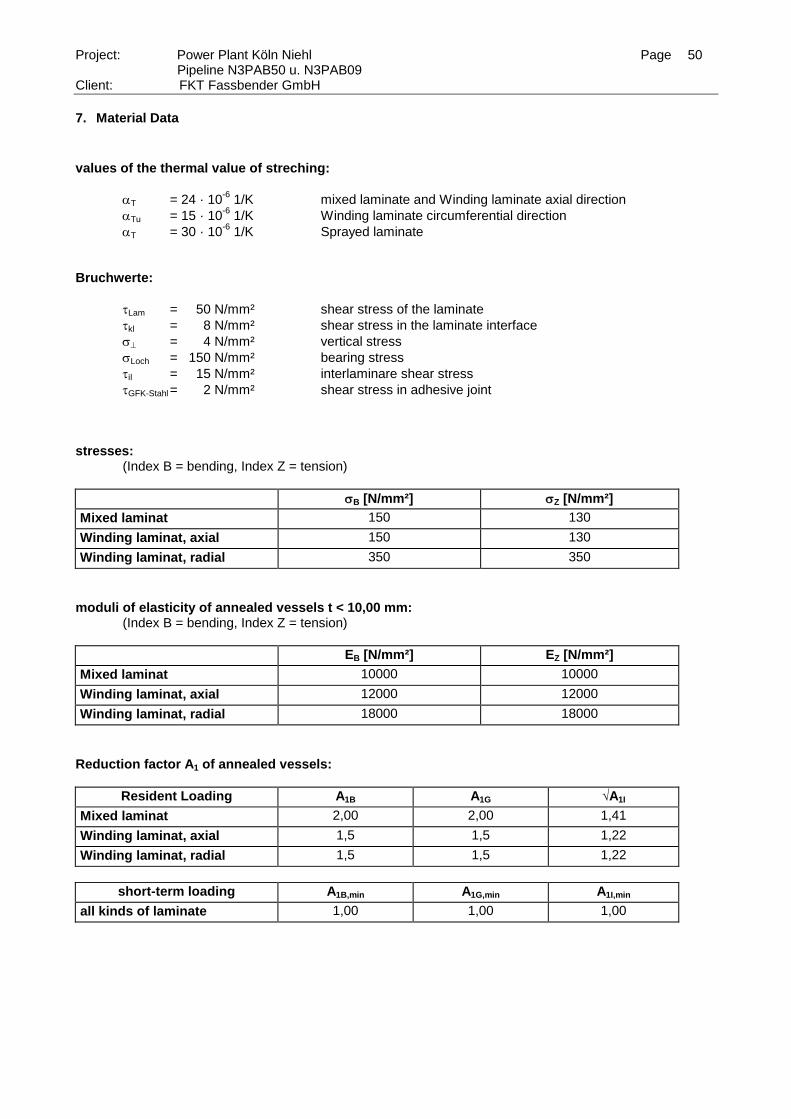
7. Material Data
values of the thermal value of streching:
T = 24 · 10-6
1/K mixed laminate and Winding laminate axial direction
Tu = 15 · 10-6
1/K Winding laminate circumferential direction
T = 30 · 10-6
1/K Sprayed laminate
Bruchwerte:
Lam = 50 N/mm² shear stress of the laminate
kl = 8 N/mm² shear stress in the laminate interface
= 4 N/mm² vertical stress
Loch = 150 N/mm² bearing stress
il = 15 N/mm² interlaminare shear stress
GFK-Stahl = 2 N/mm² shear stress in adhesive joint
stresses: (Index B = bending, Index Z = tension)
B [N/mm²] Z [N/mm²]
Mixed laminat 150 130
Winding laminat, axial 150 130
Winding laminat, radial 350 350
moduli of elasticity of annealed vessels t < 10,00 mm: (Index B = bending, Index Z = tension)
EB [N/mm²] EZ [N/mm²]
Mixed laminat 10000 10000
Winding laminat, axial 12000 12000
Winding laminat, radial 18000 18000
Reduction factor A1 of annealed vessels:
Resident Loading A1B A1G √A1I
Mixed laminat 2,00 2,00 1,41
Winding laminat, axial 1,5 1,5 1,22
Winding laminat, radial 1,5 1,5 1,22
short-term loading A1B,min A1G,min A1I,min
all kinds of laminate 1,00 1,00 1,00
Page 51
Ingenieurbüro für konstruktiven Ingenieurbau Dr.-Ing. Ingo Lukas
Am Krummen Morgen 1 67727 Lohnsfeld Tel. 06302 - 982844 Fax 06302 - 982846
Appendix 1 FE-Analysis Pipes
Page 52
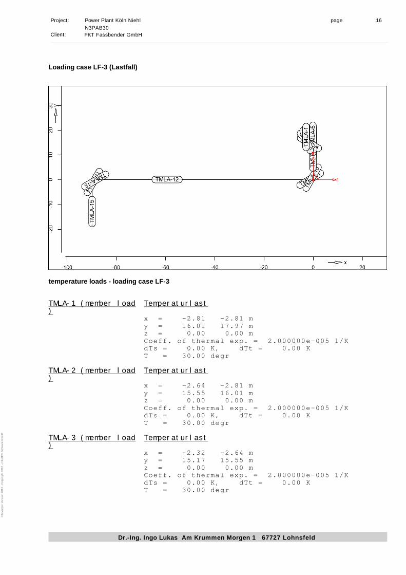
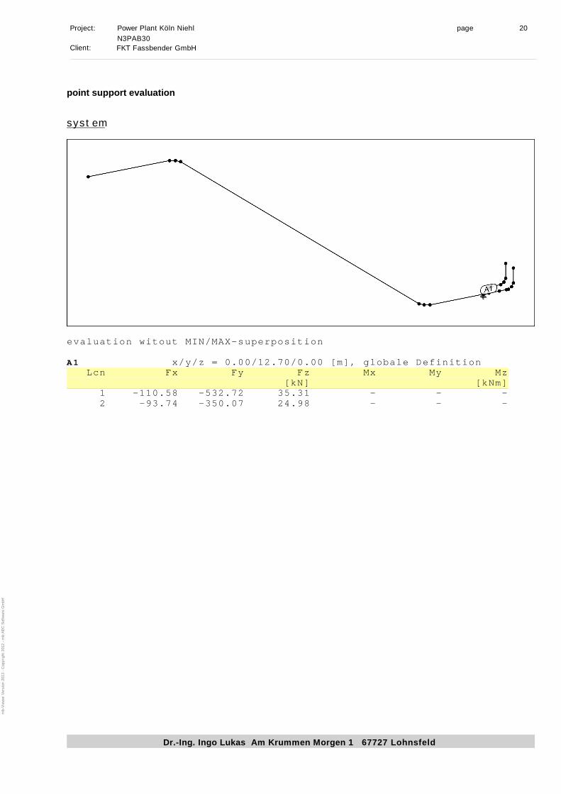
Project: Power Plant Köln Niehl page 1
Dr.-Ing. Ingo Lukas Am Krummen Morgen 1 67727 Lohnsfeld
N3PAB30
Client:FKT Fassbender GmbH
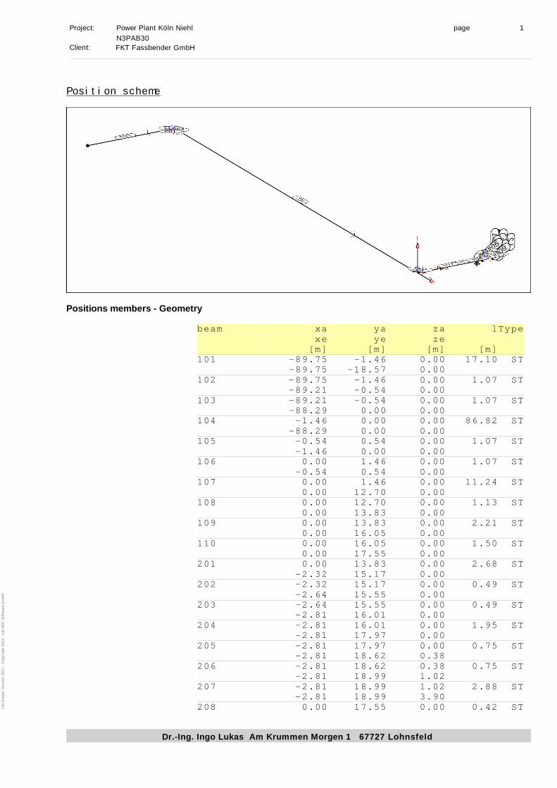
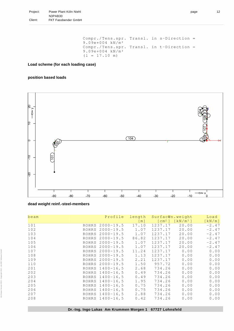
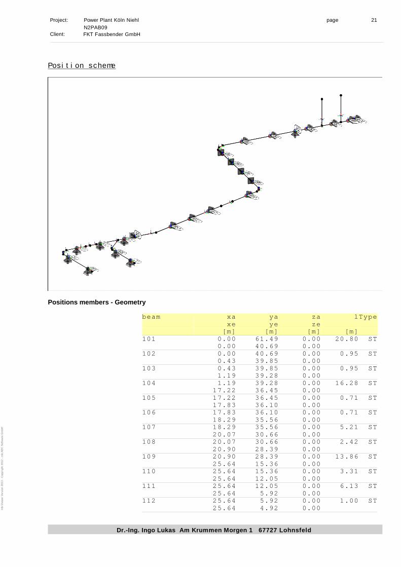
Position scheme
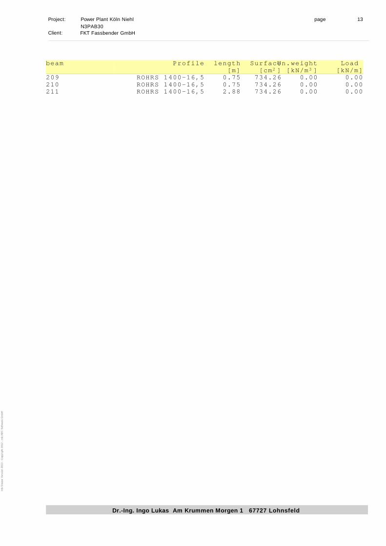
Positions members - Geometry
beam xa ya za lType
xe ye ze
[m] [m] [m] [m]
101 -89.75 -1.46 0.00 17.10 ST
-89.75 -18.57 0.00
102 -89.75 -1.46 0.00 1.07 ST
-89.21 -0.54 0.00
103 -89.21 -0.54 0.00 1.07 ST
-88.29 0.00 0.00
104 -1.46 0.00 0.00 86.82 ST
-88.29 0.00 0.00
105 -0.54 0.54 0.00 1.07 ST
-1.46 0.00 0.00
106 0.00 1.46 0.00 1.07 ST
-0.54 0.54 0.00
107 0.00 1.46 0.00 11.24 ST
0.00 12.70 0.00
108 0.00 12.70 0.00 1.13 ST
0.00 13.83 0.00
109 0.00 13.83 0.00 2.21 ST
0.00 16.05 0.00
110 0.00 16.05 0.00 1.50 ST
0.00 17.55 0.00
201 0.00 13.83 0.00 2.68 ST
-2.32 15.17 0.00
202 -2.32 15.17 0.00 0.49 ST
-2.64 15.55 0.00
203 -2.64 15.55 0.00 0.49 ST
-2.81 16.01 0.00
204 -2.81 16.01 0.00 1.95 ST
-2.81 17.97 0.00
205 -2.81 17.97 0.00 0.75 ST
-2.81 18.62 0.38
206 -2.81 18.62 0.38 0.75 ST
-2.81 18.99 1.02
207 -2.81 18.99 1.02 2.88 ST
-2.81 18.99 3.90
208 0.00 17.55 0.00 0.42 ST
mb-V
iew
er V
ersion 2013 - C
opyright 2012 - m
b A
EC
S
oftw
are G
mbH
Page 53
Project: Power Plant Köln Niehl page 2
Dr.-Ing. Ingo Lukas Am Krummen Morgen 1 67727 Lohnsfeld
N3PAB30
Client:FKT Fassbender GmbH
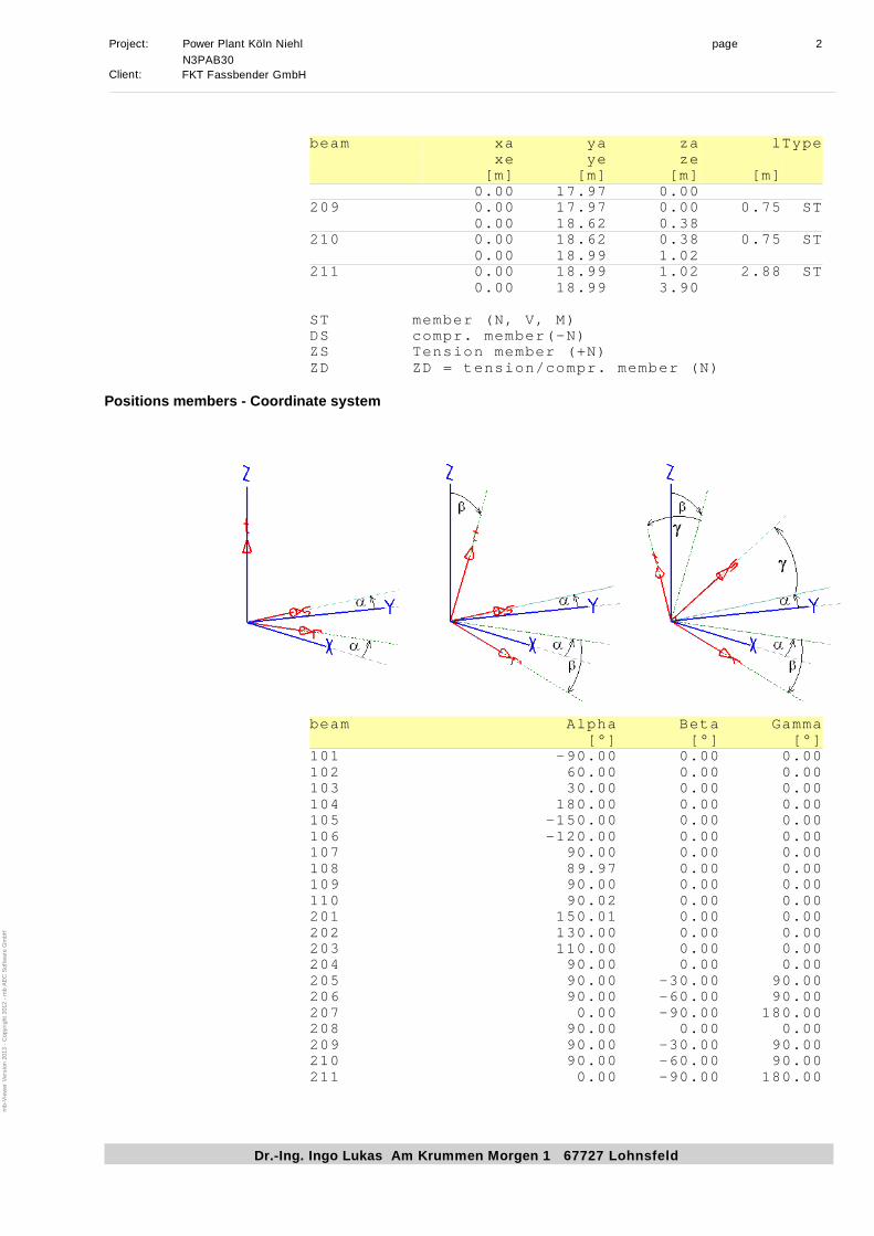
beam xa ya za lType
xe ye ze
[m] [m] [m] [m]
0.00 17.97 0.00
209 0.00 17.97 0.00 0.75 ST
0.00 18.62 0.38
210 0.00 18.62 0.38 0.75 ST
0.00 18.99 1.02
211 0.00 18.99 1.02 2.88 ST
0.00 18.99 3.90
ST member (N, V, M)
DS compr. member(-N)
ZS Tension member (+N)
ZD ZD = tension/compr. member (N)
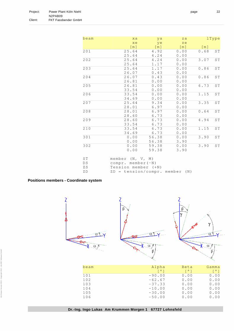
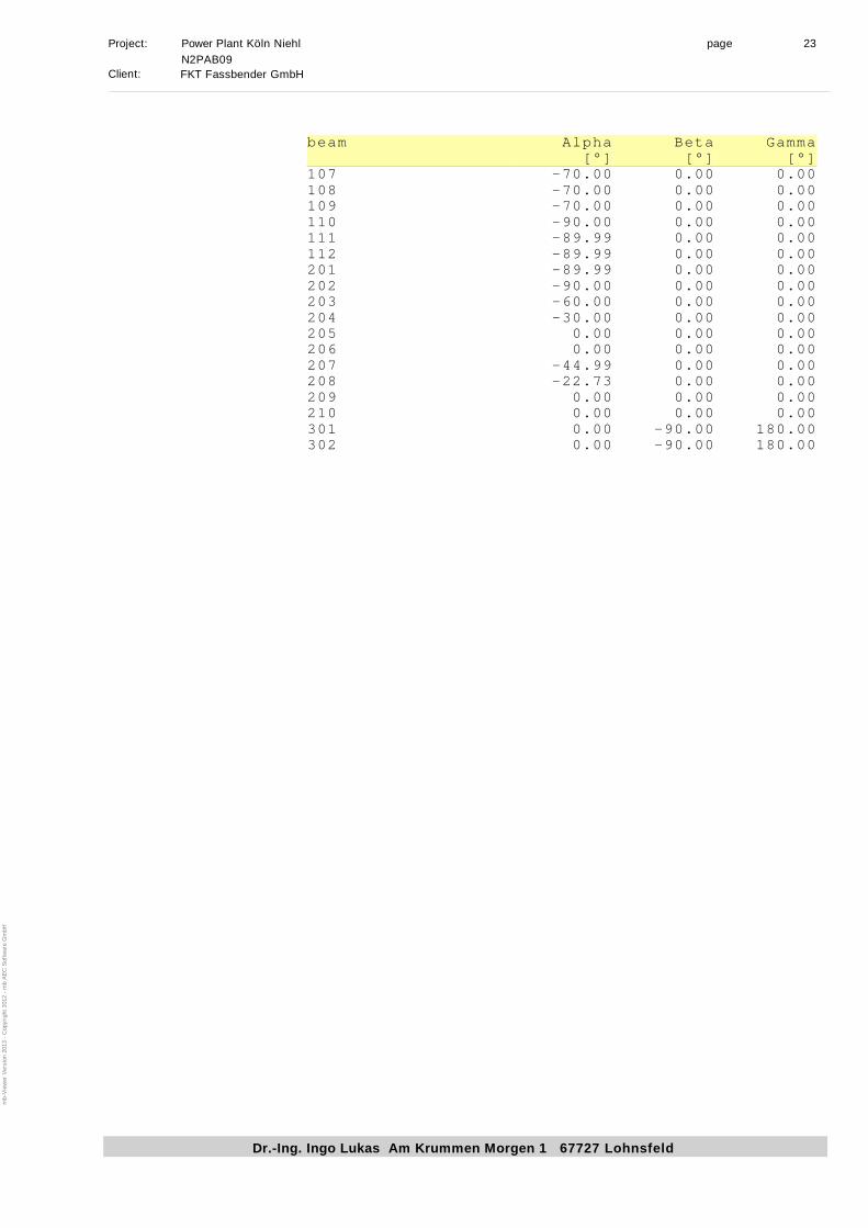
Positions members - Coordinate system
beam Alpha Beta Gamma
[°] [°] [°]
101 -90.00 0.00 0.00
102 60.00 0.00 0.00
103 30.00 0.00 0.00
104 180.00 0.00 0.00
105 -150.00 0.00 0.00
106 -120.00 0.00 0.00
107 90.00 0.00 0.00
108 89.97 0.00 0.00
109 90.00 0.00 0.00
110 90.02 0.00 0.00
201 150.01 0.00 0.00
202 130.00 0.00 0.00
203 110.00 0.00 0.00
204 90.00 0.00 0.00
205 90.00 -30.00 90.00
206 90.00 -60.00 90.00
207 0.00 -90.00 180.00
208 90.00 0.00 0.00
209 90.00 -30.00 90.00
210 90.00 -60.00 90.00
211 0.00 -90.00 180.00
mb-V
iew
er V
ersion 2013 - C
opyright 2012 - m
b A
EC
S
oftw
are G
mbH
Page 54
Project: Power Plant Köln Niehl page 3
Dr.-Ing. Ingo Lukas Am Krummen Morgen 1 67727 Lohnsfeld
N3PAB30
Client:FKT Fassbender GmbH
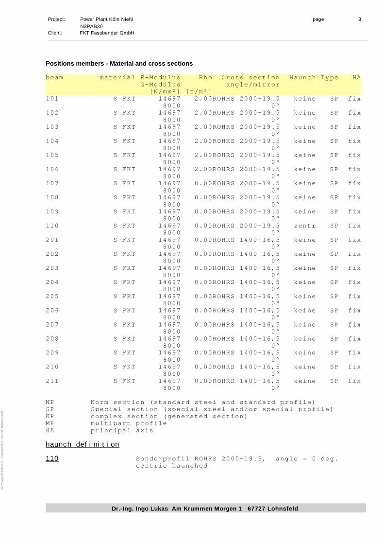
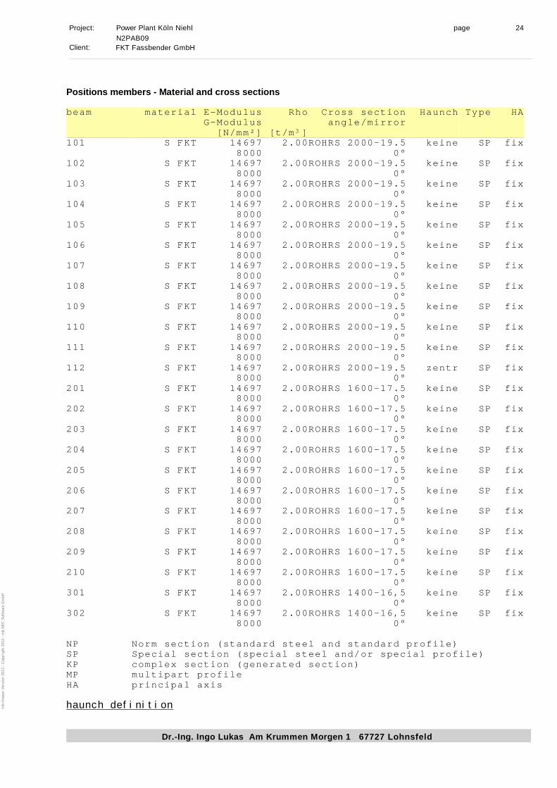
Positions members - Material and cross sections
beam material E-Modulus Rho Cross section Haunch Type HA
G-Modulus angle/mirror
[N/mm²] [t/m
3
]
101 S FKT 14697 2.00ROHRS 2000-19.5 keine SP fix
8000 0°
102 S FKT 14697 2.00ROHRS 2000-19.5 keine SP fix
8000 0°
103 S FKT 14697 2.00ROHRS 2000-19.5 keine SP fix
8000 0°
104 S FKT 14697 2.00ROHRS 2000-19.5 keine SP fix
8000 0°
105 S FKT 14697 2.00ROHRS 2000-19.5 keine SP fix
8000 0°
106 S FKT 14697 2.00ROHRS 2000-19.5 keine SP fix
8000 0°
107 S FKT 14697 0.00ROHRS 2000-19.5 keine SP fix
8000 0°
108 S FKT 14697 0.00ROHRS 2000-19.5 keine SP fix
8000 0°
109 S FKT 14697 0.00ROHRS 2000-19.5 keine SP fix
8000 0°
110 S FKT 14697 0.00ROHRS 2000-19.5 zentr SP fix
8000 0°
201 S FKT 14697 0.00ROHRS 1400-16,5 keine SP fix
8000 0°
202 S FKT 14697 0.00ROHRS 1400-16,5 keine SP fix
8000 0°
203 S FKT 14697 0.00ROHRS 1400-16,5 keine SP fix
8000 0°
204 S FKT 14697 0.00ROHRS 1400-16,5 keine SP fix
8000 0°
205 S FKT 14697 0.00ROHRS 1400-16,5 keine SP fix
8000 0°
206 S FKT 14697 0.00ROHRS 1400-16,5 keine SP fix
8000 0°
207 S FKT 14697 0.00ROHRS 1400-16,5 keine SP fix
8000 0°
208 S FKT 14697 0.00ROHRS 1400-16,5 keine SP fix
8000 0°
209 S FKT 14697 0.00ROHRS 1400-16,5 keine SP fix
8000 0°
210 S FKT 14697 0.00ROHRS 1400-16,5 keine SP fix
8000 0°
211 S FKT 14697 0.00ROHRS 1400-16,5 keine SP fix
8000 0°
NP Norm section (standard steel and standard profile)
SP Special section (special steel and/or special profile)
KP complex section (generated section)
MP multipart profile
HA principal axis
haunch definition
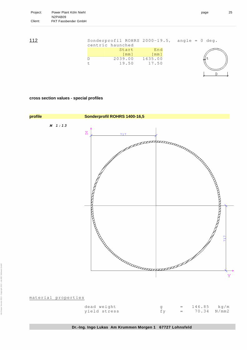
110Sonderprofil ROHRS 2000-19.5, angle = 0 deg.
centric haunched
mb-V
iew
er V
ersion 2013 - C
opyright 2012 - m
b A
EC
S
oftw
are G
mbH
Page 55
Project: Power Plant Köln Niehl page 4
Dr.-Ing. Ingo Lukas Am Krummen Morgen 1 67727 Lohnsfeld
N3PAB30
Client:FKT Fassbender GmbH
Start End
[mm] [mm]
D 2039.00 1530.00
t 19.50 15.00
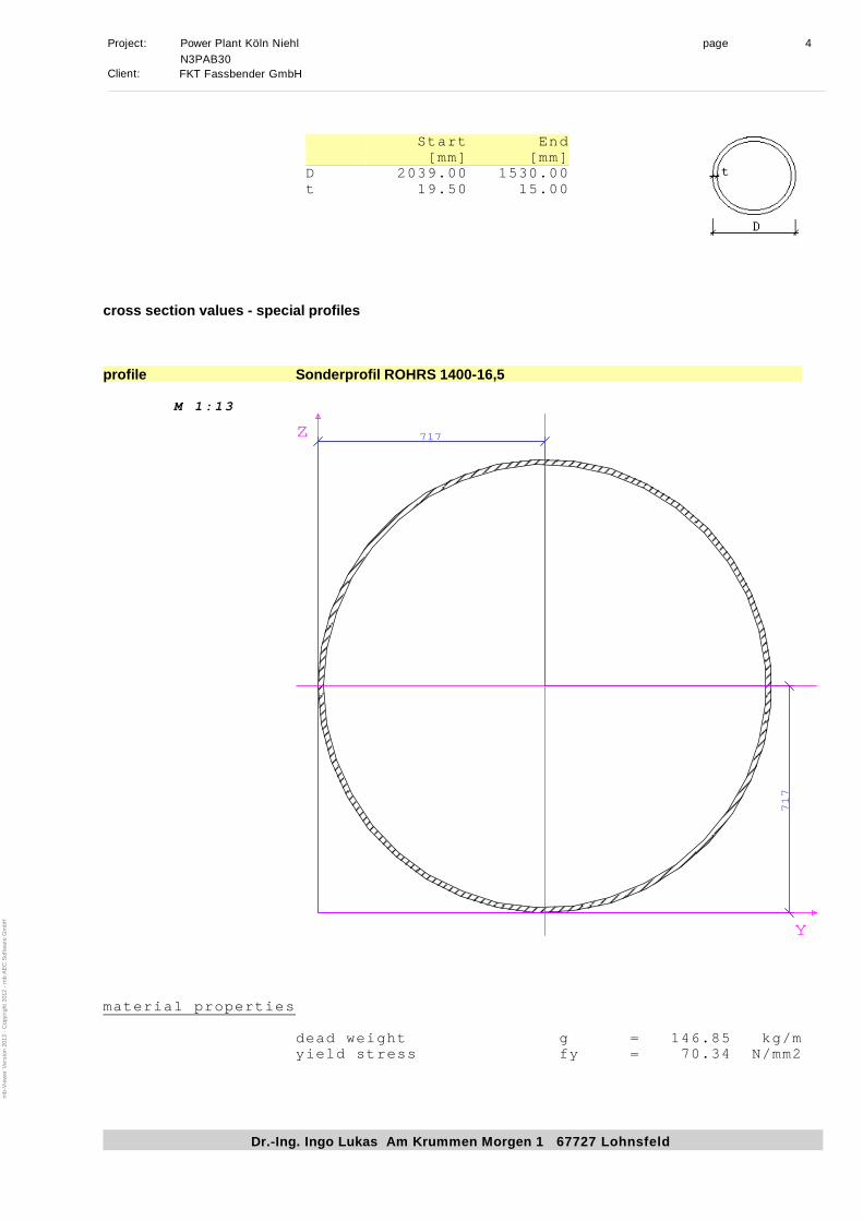
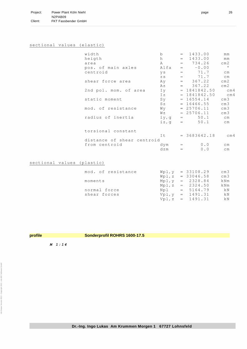
cross section values - special profiles
profile Sonderprofil ROHRS 1400-16,5
M 1:13
717
717
Y
Z
material properties
dead weight g = 146.85 kg/m
yield stress fy = 70.34 N/mm2
mb-V
iew
er V
ersion 2013 - C
opyright 2012 - m
b A
EC
S
oftw
are G
mbH
Page 56
Project: Power Plant Köln Niehl page 5
Dr.-Ing. Ingo Lukas Am Krummen Morgen 1 67727 Lohnsfeld
N3PAB30
Client:FKT Fassbender GmbH
sectional values (elastic)
width b = 1433.00 mm
heigth h = 1433.00 mm
area A = 734.26 cm2
pos. of main axles Alfa = -0.00 °
centroid ys = 71.7 cm
zs = 71.7 cm
shear force area Ay = 367.22 cm2
Az = 367.22 cm2
2nd pol. mom. of area Iy = 1841842.50 cm4
Iz = 1841842.50 cm4
static moment Sy = 16554.14 cm3
Sz = 16466.55 cm3
mod. of resistance Wy = 25706.11 cm3
Wz = 25706.11 cm3
radius of inertia iy,g = 50.1 cm
iz,g = 50.1 cm
torsional constant
It = 3683642.18 cm4
distance of shear centroid
from centroid dym = 0.0 cm
dzm = 0.0 cm
sectional values (plastic)
mod. of resistance Wpl,y = 33108.29 cm3
Wpl,z = 33046.58 cm3
moments Mpl,y = 2328.84 kNm
Mpl,z = 2324.50 kNm
normal force Npl = 5164.79 kN
shear forces Vpl,y = 1491.31 kN
Vpl,z = 1491.31 kN
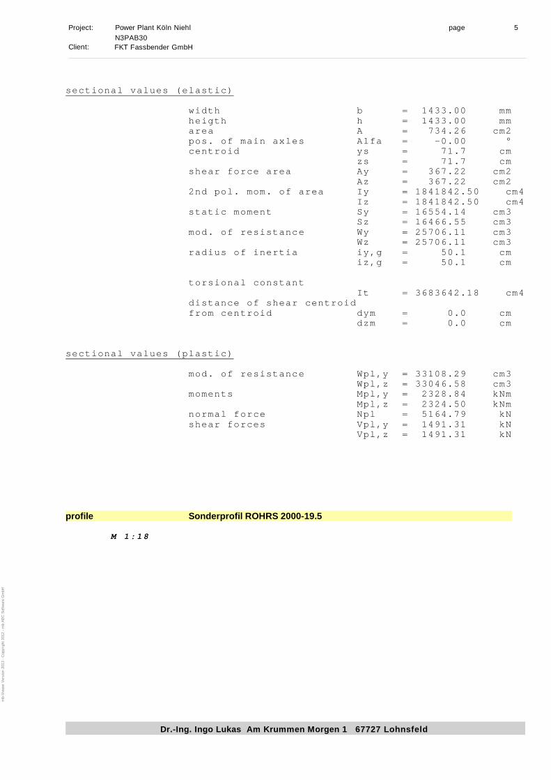
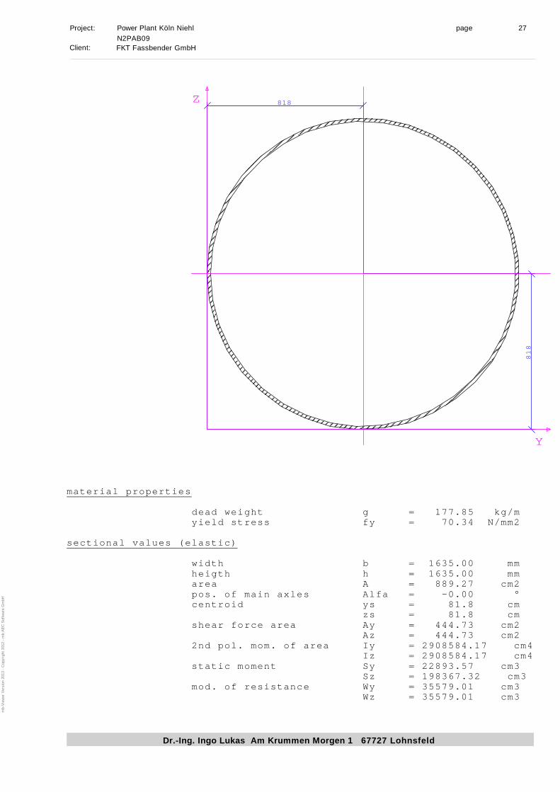
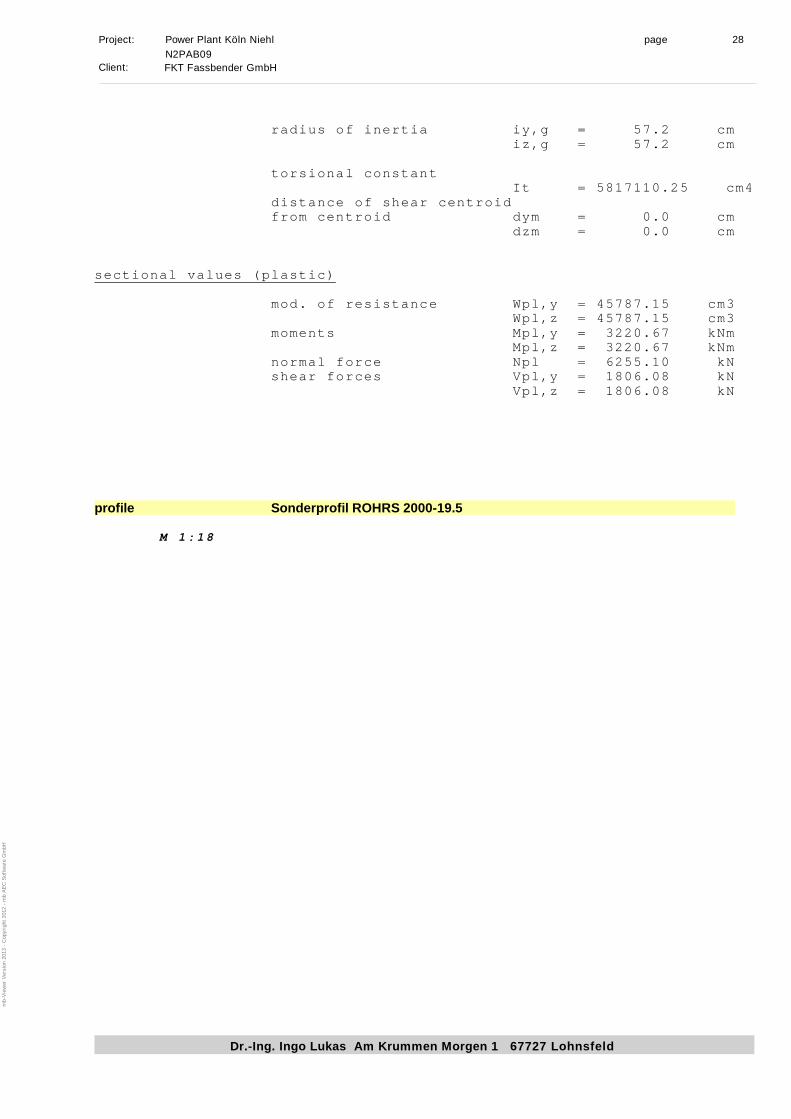
profile Sonderprofil ROHRS 2000-19.5
M 1:18
mb-V
iew
er V
ersion 2013 - C
opyright 2012 - m
b A
EC
S
oftw
are G
mbH
Page 57
Project: Power Plant Köln Niehl page 6
Dr.-Ing. Ingo Lukas Am Krummen Morgen 1 67727 Lohnsfeld
N3PAB30
Client:FKT Fassbender GmbH
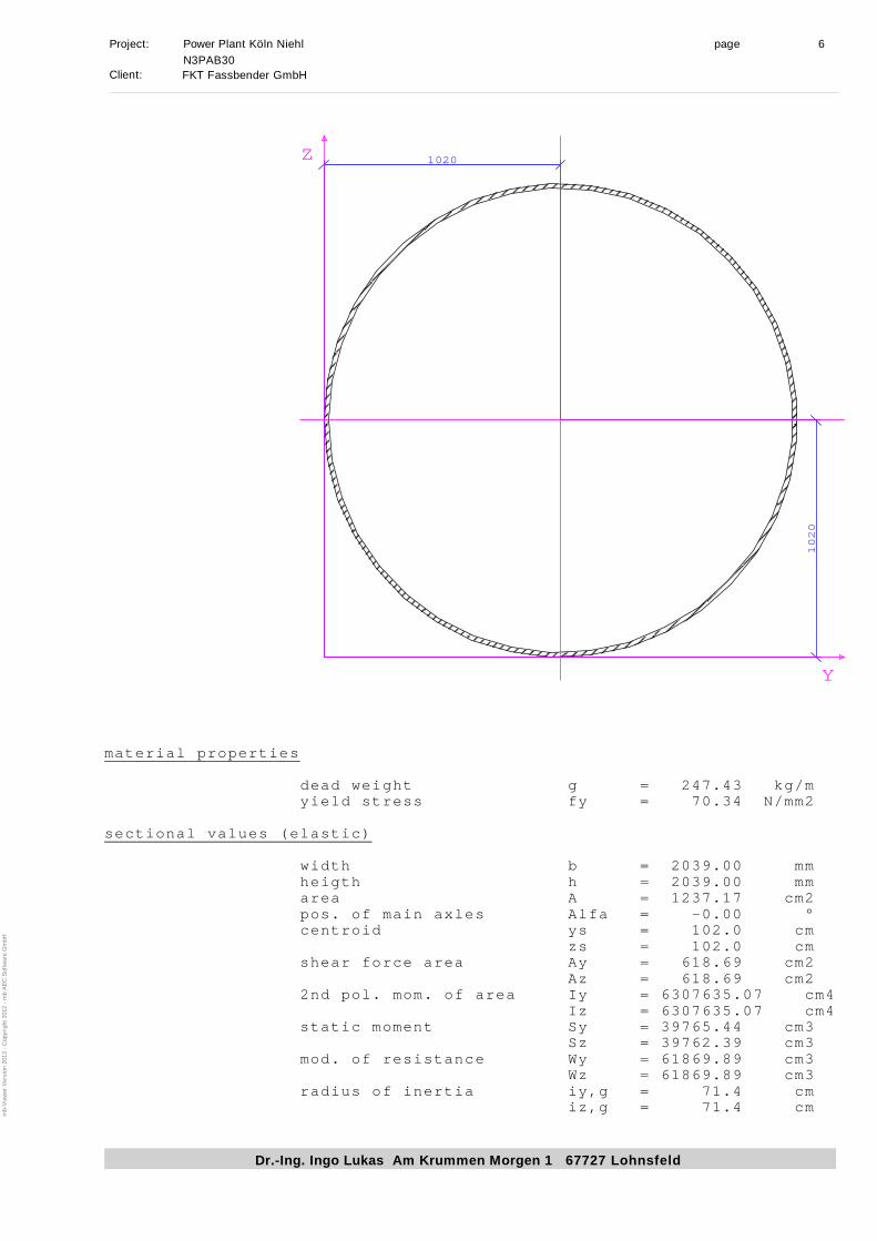
1020
1020
Y
Z
material properties
dead weight g = 247.43 kg/m
yield stress fy = 70.34 N/mm2
sectional values (elastic)
width b = 2039.00 mm
heigth h = 2039.00 mm
area A = 1237.17 cm2
pos. of main axles Alfa = -0.00 °
centroid ys = 102.0 cm
zs = 102.0 cm
shear force area Ay = 618.69 cm2
Az = 618.69 cm2
2nd pol. mom. of area Iy = 6307635.07 cm4
Iz = 6307635.07 cm4
static moment Sy = 39765.44 cm3
Sz = 39762.39 cm3
mod. of resistance Wy = 61869.89 cm3
Wz = 61869.89 cm3
radius of inertia iy,g = 71.4 cm
iz,g = 71.4 cm
mb-V
iew
er V
ersion 2013 - C
opyright 2012 - m
b A
EC
S
oftw
are G
mbH
Page 58
Project: Power Plant Köln Niehl page 7
Dr.-Ing. Ingo Lukas Am Krummen Morgen 1 67727 Lohnsfeld
N3PAB30
Client:FKT Fassbender GmbH
torsional constant
It = 12615170.08 cm4
distance of shear centroid
from centroid dym = 0.0 cm
dzm = 0.0 cm
sectional values (plastic)
mod. of resistance Wpl,y = 79431.73 cm3
Wpl,z = 79402.96 cm3
moments Mpl,y = 5587.23 kNm
Mpl,z = 5585.20 kNm
normal force Npl = 8702.23 kN
shear forces Vpl,y = 2512.54 kN
Vpl,z = 2512.54 kN
mb-V
iew
er V
ersion 2013 - C
opyright 2012 - m
b A
EC
S
oftw
are G
mbH
Page 59
Project: Power Plant Köln Niehl page 8
Dr.-Ing. Ingo Lukas Am Krummen Morgen 1 67727 Lohnsfeld
N3PAB30
Client:FKT Fassbender GmbH
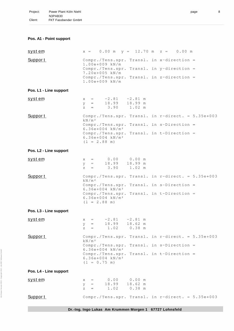
Pos. A1 - Point support
systemx = 0.00 m y = 12.70 m z = 0.00 m
SupportCompr./Tens.spr. Transl. in x-direction =
1.00e+009 kN/m
Compr./Tens.spr. Transl. in y-direction =
7.20e+005 kN/m
Compr./Tens.spr. Transl. in z-direction =
1.00e+009 kN/m
Pos. L1 - Line support
systemx = -2.81 -2.81 m
y = 18.99 18.99 m
z = 3.90 1.02 m
SupportCompr./Tens.spr. Transl. in r-direct. = 5.35e+003
kN/m²
Compr./Tens.spr. Transl. in s-Direction =
6.36e+004 kN/m²
Compr./Tens.spr. Transl. in t-Direction =
6.36e+004 kN/m²
(l = 2.88 m)
Pos. L2 - Line support
systemx = 0.00 0.00 m
y = 18.99 18.99 m
z = 3.90 1.02 m
SupportCompr./Tens.spr. Transl. in r-direct. = 5.35e+003
kN/m²
Compr./Tens.spr. Transl. in s-Direction =
6.36e+004 kN/m²
Compr./Tens.spr. Transl. in t-Direction =
6.36e+004 kN/m²
(l = 2.88 m)
Pos. L3 - Line support
systemx = -2.81 -2.81 m
y = 18.99 18.62 m
z = 1.02 0.38 m
SupportCompr./Tens.spr. Transl. in r-direct. = 5.35e+003
kN/m²
Compr./Tens.spr. Transl. in s-Direction =
6.36e+004 kN/m²
Compr./Tens.spr. Transl. in t-Direction =
6.36e+004 kN/m²
(l = 0.75 m)
Pos. L4 - Line support
systemx = 0.00 0.00 m
y = 18.99 18.62 m
z = 1.02 0.38 m
SupportCompr./Tens.spr. Transl. in r-direct. = 5.35e+003
mb-V
iew
er V
ersion 2013 - C
opyright 2012 - m
b A
EC
S
oftw
are G
mbH
Page 60
Project: Power Plant Köln Niehl page 9
Dr.-Ing. Ingo Lukas Am Krummen Morgen 1 67727 Lohnsfeld
N3PAB30
Client:FKT Fassbender GmbH
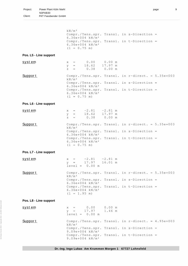
kN/m²
Compr./Tens.spr. Transl. in s-Direction =
6.36e+004 kN/m²
Compr./Tens.spr. Transl. in t-Direction =
6.36e+004 kN/m²
(l = 0.75 m)
Pos. L5 - Line support
systemx = 0.00 0.00 m
y = 18.62 17.97 m
z = 0.38 0.00 m
SupportCompr./Tens.spr. Transl. in r-direct. = 5.35e+003
kN/m²
Compr./Tens.spr. Transl. in s-Direction =
6.36e+004 kN/m²
Compr./Tens.spr. Transl. in t-Direction =
6.36e+004 kN/m²
(l = 0.75 m)
Pos. L6 - Line support
systemx = -2.81 -2.81 m
y = 18.62 17.97 m
z = 0.38 0.00 m
SupportCompr./Tens.spr. Transl. in r-direct. = 5.35e+003
kN/m²
Compr./Tens.spr. Transl. in s-Direction =
6.36e+004 kN/m²
Compr./Tens.spr. Transl. in t-Direction =
6.36e+004 kN/m²
(l = 0.75 m)
Pos. L7 - Line support
systemx = -2.81 -2.81 m
y = 17.97 16.01 m
level = 0.00 m
SupportCompr./Tens.spr. Transl. in r-direct. = 5.35e+003
kN/m²
Compr./Tens.spr. Transl. in s-Direction =
6.36e+004 kN/m²
Compr./Tens.spr. Transl. in t-Direction =
6.36e+004 kN/m²
(l = 1.95 m)
Pos. L8 - Line support
systemx = 0.00 0.00 m
y = 17.97 1.46 m
level = 0.00 m
SupportCompr./Tens.spr. Transl. in r-direct. = 4.95e+003
kN/m²
Compr./Tens.spr. Transl. in s-Direction =
9.09e+004 kN/m²
Compr./Tens.spr. Transl. in t-Direction =
9.09e+004 kN/m²
mb-V
iew
er V
ersion 2013 - C
opyright 2012 - m
b A
EC
S
oftw
are G
mbH
Page 61
Project: Power Plant Köln Niehl page 10
Dr.-Ing. Ingo Lukas Am Krummen Morgen 1 67727 Lohnsfeld
N3PAB30
Client:FKT Fassbender GmbH
(l = 16.50 m)
Pos. L9 - Line support
systemx = -2.81 -2.64 m
y = 16.01 15.55 m
level = 0.00 m
SupportCompr./Tens.spr. Transl. in r-direct. = 5.35e+003
kN/m²
Compr./Tens.spr. Transl. in s-Direction =
6.36e+004 kN/m²
Compr./Tens.spr. Transl. in t-Direction =
6.36e+004 kN/m²
(l = 0.49 m)
Pos. L10 - Line support
systemx = -2.64 -2.32 m
y = 15.55 15.17 m
level = 0.00 m
SupportCompr./Tens.spr. Transl. in r-direct. = 5.35e+003
kN/m²
Compr./Tens.spr. Transl. in s-Direction =
6.36e+004 kN/m²
Compr./Tens.spr. Transl. in t-Direction =
6.36e+004 kN/m²
(l = 0.49 m)
Pos. L11 - Line support
systemx = -2.32 0.00 m
y = 15.17 13.83 m
level = 0.00 m
SupportCompr./Tens.spr. Transl. in r-direct. = 5.35e+003
kN/m²
Compr./Tens.spr. Transl. in s-Direction =
6.36e+004 kN/m²
Compr./Tens.spr. Transl. in t-Direction =
6.36e+004 kN/m²
(l = 2.68 m)
Pos. L12 - Line support
systemx = 0.00 -0.54 m
y = 1.46 0.54 m
level = 0.00 m
SupportCompr./Tens.spr. Transl. in r-direct. = 4.95e+003
kN/m²
Compr./Tens.spr. Transl. in s-Direction =
9.09e+004 kN/m²
Compr./Tens.spr. Transl. in t-Direction =
9.09e+004 kN/m²
(l = 1.07 m)
Pos. L13 - Line support
systemx = -0.54 -1.46 m
mb-V
iew
er V
ersion 2013 - C
opyright 2012 - m
b A
EC
S
oftw
are G
mbH
Page 62
Project: Power Plant Köln Niehl page 11
Dr.-Ing. Ingo Lukas Am Krummen Morgen 1 67727 Lohnsfeld
N3PAB30
Client:FKT Fassbender GmbH
y = 0.54 0.00 m
level = 0.00 m
SupportCompr./Tens.spr. Transl. in r-direct. = 4.95e+003
kN/m²
Compr./Tens.spr. Transl. in s-Direction =
9.09e+004 kN/m²
Compr./Tens.spr. Transl. in t-Direction =
9.09e+004 kN/m²
(l = 1.07 m)
Pos. L14 - Line support
systemx = -1.46 -88.29 m
y = 0.00 0.00 m
level = 0.00 m
SupportCompr./Tens.spr. Transl. in r-direct. = 4.95e+003
kN/m²
Compr./Tens.spr. Transl. in s-Direction =
9.09e+004 kN/m²
Compr./Tens.spr. Transl. in t-Direction =
9.09e+004 kN/m²
(l = 86.82 m)
Pos. L15 - Line support
systemx = -88.29 -89.21 m
y = 0.00 -0.54 m
level = 0.00 m
SupportCompr./Tens.spr. Transl. in r-direct. = 4.95e+003
kN/m²
Compr./Tens.spr. Transl. in s-Direction =
9.09e+004 kN/m²
Compr./Tens.spr. Transl. in t-Direction =
9.09e+004 kN/m²
(l = 1.07 m)
Pos. L16 - Line support
systemx = -89.21 -89.75 m
y = -0.54 -1.46 m
level = 0.00 m
SupportCompr./Tens.spr. Transl. in r-direct. = 4.95e+003
kN/m²
Compr./Tens.spr. Transl. in s-Direction =
9.09e+004 kN/m²
Compr./Tens.spr. Transl. in t-Direction =
9.09e+004 kN/m²
(l = 1.07 m)
Pos. L17 - Line support
systemx = -89.75 -89.75 m
y = -1.46 -18.57 m
level = 0.00 m
SupportCompr./Tens.spr. Transl. in r-direct. = 4.95e+003
kN/m²
mb-V
iew
er V
ersion 2013 - C
opyright 2012 - m
b A
EC
S
oftw
are G
mbH
Page 63
Project: Power Plant Köln Niehl page 12
Dr.-Ing. Ingo Lukas Am Krummen Morgen 1 67727 Lohnsfeld
N3PAB30
Client:FKT Fassbender GmbH
Compr./Tens.spr. Transl. in s-Direction =
9.09e+004 kN/m²
Compr./Tens.spr. Transl. in t-Direction =
9.09e+004 kN/m²
(l = 17.10 m)
Load scheme (for each loading case)
position based loads
dead weight reinf.-steel-members
beam Profile length SurfaceUn.weight Load
[m] [cm
2
] [kN/m
3
] [kN/m]
101 ROHRS 2000-19.5 17.10 1237.17 20.00 -2.47
102 ROHRS 2000-19.5 1.07 1237.17 20.00 -2.47
103 ROHRS 2000-19.5 1.07 1237.17 20.00 -2.47
104 ROHRS 2000-19.5 86.82 1237.17 20.00 -2.47
105 ROHRS 2000-19.5 1.07 1237.17 20.00 -2.47
106 ROHRS 2000-19.5 1.07 1237.17 20.00 -2.47
107 ROHRS 2000-19.5 11.24 1237.17 0.00 0.00
108 ROHRS 2000-19.5 1.13 1237.17 0.00 0.00
109 ROHRS 2000-19.5 2.21 1237.17 0.00 0.00
110 ROHRS 2000-19.5 1.50 957.72 0.00 0.00
201 ROHRS 1400-16,5 2.68 734.26 0.00 0.00
202 ROHRS 1400-16,5 0.49 734.26 0.00 0.00
203 ROHRS 1400-16,5 0.49 734.26 0.00 0.00
204 ROHRS 1400-16,5 1.95 734.26 0.00 0.00
205 ROHRS 1400-16,5 0.75 734.26 0.00 0.00
206 ROHRS 1400-16,5 0.75 734.26 0.00 0.00
207 ROHRS 1400-16,5 2.88 734.26 0.00 0.00
208 ROHRS 1400-16,5 0.42 734.26 0.00 0.00
mb-V
iew
er V
ersion 2013 - C
opyright 2012 - m
b A
EC
S
oftw
are G
mbH
Page 64
Project: Power Plant Köln Niehl page 13
Dr.-Ing. Ingo Lukas Am Krummen Morgen 1 67727 Lohnsfeld
N3PAB30
Client:FKT Fassbender GmbH
beam Profile length SurfaceUn.weight Load
[m] [cm
2
] [kN/m
3
] [kN/m]
209 ROHRS 1400-16,5 0.75 734.26 0.00 0.00
210 ROHRS 1400-16,5 0.75 734.26 0.00 0.00
211 ROHRS 1400-16,5 2.88 734.26 0.00 0.00
mb-V
iew
er V
ersion 2013 - C
opyright 2012 - m
b A
EC
S
oftw
are G
mbH
Page 65
Project: Power Plant Köln Niehl page 14
Dr.-Ing. Ingo Lukas Am Krummen Morgen 1 67727 Lohnsfeld
N3PAB30
Client:FKT Fassbender GmbH
Loading case LF-2 (Lastfall)
single loads - loading case LF-2
position Type Load x y z Description
[kN]/[kNm] [m] [m] [m]
P1 Pr -1570.800 0.00 1.46 0.00 Punktlast
P2 Pr 1570.800 0.00 16.05 0.00 Punktlast
P3 Pr 769.700 0.00 17.55 0.00 Punktlast
P4 Pr 769.700 0.00 17.97 0.00 Punktlast
P5 Pr -1570.800 0.00 16.05 0.00 Punktlast
P6 Pr -769.700 0.00 17.55 0.00 Punktlast
P7 Pr -769.700 0.00 13.83 0.00 Punktlast
P8 Pr 769.700 -2.32 15.17 0.00 Punktlast
P9 Pr 769.700 -2.64 15.55 0.00 Punktlast
P10 Pr 769.700 -2.81 16.01 0.00 Punktlast
P11 Pr 769.700 -2.81 17.97 0.00 Punktlast
P12 Pr -769.700 -2.32 15.17 0.00 Punktlast
P13 Pr -769.700 -2.65 15.58 0.00 Punktlast
P14 Pr -769.700 -2.81 16.01 0.00 Punktlast
P15 Pr 1570.800 -0.54 0.54 0.00 Punktlast
P16 Pr -1570.800 0.00 1.46 0.00 Punktlast
P17 Pr -1570.800 -0.54 0.54 0.00 Punktlast
P18 Pr 1570.800 -1.46 0.00 0.00 Punktlast
P19 Pr -1570.800 -1.46 0.00 0.00 Punktlast
P20 Pr 1570.800 -88.29 0.00 0.00 Punktlast
P21 Pr 1570.800 -88.29 0.00 0.00 Punktlast
P22 Pr 1570.800 -89.21 -0.54 0.00 Punktlast
P23 Pr 1570.800 -89.75 -18.57 0.00 Punktlast
P24 Pr -1570.800 -89.75 -1.46 0.00 Punktlast
P25 Pr -1570.800 -89.75 -1.46 0.00 Punktlast
P26 Pr -1570.800 -89.21 -0.54 0.00 Punktlast
P27 Pr 769.700 -2.81 18.62 0.38 Punktlast
P28 Pr 769.700 -2.81 18.99 1.02 Punktlast
P29 Pr 769.700 -2.81 18.99 3.90 Punktlast
mb-V
iew
er V
ersion 2013 - C
opyright 2012 - m
b A
EC
S
oftw
are G
mbH
Page 66
Project: Power Plant Köln Niehl page 15
Dr.-Ing. Ingo Lukas Am Krummen Morgen 1 67727 Lohnsfeld
N3PAB30
Client:FKT Fassbender GmbH
position Type Load x y z Description
[kN]/[kNm] [m] [m] [m]
P30 Pr -769.700 -2.81 17.97 0.00 Punktlast
P31 Pr -769.700 -2.81 18.62 0.38 Punktlast
P32 Pr -769.700 -2.81 18.99 1.02 Punktlast
P33 Pr 769.700 0.00 18.62 0.38 Punktlast
P34 Pr 769.700 0.00 18.99 1.02 Punktlast
P35 Pr -769.700 0.00 18.62 0.38 Punktlast
P36 Pr -769.700 0.00 18.99 1.02 Punktlast
P37 Pr -769.700 0.00 17.97 0.00 Punktlast
P38 Pr 769.700 0.00 18.99 3.90 Punktlast
line loads - loading case LF-2
position Type Load x y z Description
[.../m] [m] [m] [m]
LILA-1 pr/l 534.07 0.00 16.05 0.00 Linienlast
534.07 0.00 17.55 0.00
Type l: Load direction local, r-axis is
load axis
g: Load direction global
p: Load direction global projected
Load [.../m]: line load (p) -> [kN/m] line
moments (m) -> [kNm/m]
mb-V
iew
er V
ersion 2013 - C
opyright 2012 - m
b A
EC
S
oftw
are G
mbH
Page 67
Project: Power Plant Köln Niehl page 16
Dr.-Ing. Ingo Lukas Am Krummen Morgen 1 67727 Lohnsfeld
N3PAB30
Client:FKT Fassbender GmbH
Loading case LF-3 (Lastfall)
temperature loads - loading case LF-3
TMLA-1 (member load Temperaturlast
)
x = -2.81 -2.81 m
y = 16.01 17.97 m
z = 0.00 0.00 m
Coeff. of thermal exp. = 2.000000e-005 1/K
dTs = 0.00 K, dTt = 0.00 K
T = 30.00 degr
TMLA-2 (member load Temperaturlast
)
x = -2.64 -2.81 m
y = 15.55 16.01 m
z = 0.00 0.00 m
Coeff. of thermal exp. = 2.000000e-005 1/K
dTs = 0.00 K, dTt = 0.00 K
T = 30.00 degr
TMLA-3 (member load Temperaturlast
)
x = -2.32 -2.64 m
y = 15.17 15.55 m
z = 0.00 0.00 m
Coeff. of thermal exp. = 2.000000e-005 1/K
dTs = 0.00 K, dTt = 0.00 K
T = 30.00 degr
mb-V
iew
er V
ersion 2013 - C
opyright 2012 - m
b A
EC
S
oftw
are G
mbH
Page 68
Project: Power Plant Köln Niehl page 17
Dr.-Ing. Ingo Lukas Am Krummen Morgen 1 67727 Lohnsfeld
N3PAB30
Client:FKT Fassbender GmbH
TMLA-4 (member load Temperaturlast
)
x = 0.00 -2.32 m
y = 13.83 15.17 m
z = 0.00 0.00 m
Coeff. of thermal exp. = 2.000000e-005 1/K
dTs = 0.00 K, dTt = 0.00 K
T = 30.00 degr
TMLA-5 (member load Temperaturlast
)
x = 0.00 0.00 m
y = 17.55 17.97 m
z = 0.00 0.00 m
Coeff. of thermal exp. = 2.000000e-005 1/K
dTs = 0.00 K, dTt = 0.00 K
T = 30.00 degr
TMLA-6 (member load Temperaturlast
)
x = 0.00 0.00 m
y = 16.05 17.55 m
z = 0.00 0.00 m
Coeff. of thermal exp. = 2.000000e-005 1/K
dTs = 0.00 K, dTt = 0.00 K
T = 30.00 degr
TMLA-7 (member load Temperaturlast
)
x = 0.00 0.00 m
y = 13.83 16.05 m
z = 0.00 0.00 m
Coeff. of thermal exp. = 2.000000e-005 1/K
dTs = 0.00 K, dTt = 0.00 K
T = 30.00 degr
TMLA-8 (member load Temperaturlast
)
x = 0.00 0.00 m
y = 12.70 13.83 m
z = 0.00 0.00 m
Coeff. of thermal exp. = 2.000000e-005 1/K
dTs = 0.00 K, dTt = 0.00 K
T = 30.00 degr
TMLA-9 (member load Temperaturlast
)
x = 0.00 0.00 m
y = 1.46 12.70 m
z = 0.00 0.00 m
Coeff. of thermal exp. = 2.000000e-005 1/K
dTs = 0.00 K, dTt = 0.00 K
T = 30.00 degr
TMLA-10 (member Temperaturlast
load)
x = 0.00 -0.54 m
y = 1.46 0.54 m
Coeff. of thermal exp. = 2.000000e-005 1/K
dTs = 0.00 K, dTt = 0.00 K
T = 30.00 degr
mb-V
iew
er V
ersion 2013 - C
opyright 2012 - m
b A
EC
S
oftw
are G
mbH
Page 69
Project: Power Plant Köln Niehl page 18
Dr.-Ing. Ingo Lukas Am Krummen Morgen 1 67727 Lohnsfeld
N3PAB30
Client:FKT Fassbender GmbH
TMLA-11 (member Temperaturlast
load)
x = -0.54 -1.46 m
y = 0.54 0.00 m
Coeff. of thermal exp. = 2.000000e-005 1/K
dTs = 0.00 K, dTt = 0.00 K
T = 30.00 degr
TMLA-12 (member Temperaturlast
load)
x = -1.46 -88.29 m
y = 0.00 0.00 m
Coeff. of thermal exp. = 2.000000e-005 1/K
dTs = 0.00 K, dTt = 0.00 K
T = 30.00 degr
TMLA-13 (member Temperaturlast
load)
x = -89.21 -88.29 m
y = -0.54 0.00 m
z = 0.00 0.00 m
Coeff. of thermal exp. = 2.000000e-005 1/K
dTs = 0.00 K, dTt = 0.00 K
T = 30.00 degr
TMLA-14 (member Temperaturlast
load)
x = -89.75 -89.21 m
y = -1.46 -0.54 m
z = 0.00 0.00 m
Coeff. of thermal exp. = 2.000000e-005 1/K
dTs = 0.00 K, dTt = 0.00 K
T = 30.00 degr
TMLA-15 (member Temperaturlast
load)
x = -89.75 -89.75 m
y = -1.46 -18.57 m
Coeff. of thermal exp. = 2.000000e-005 1/K
dTs = 0.00 K, dTt = 0.00 K
T = 30.00 degr
TMLA-16 (member Temperaturlast
load)
x = -2.81 -2.81 m
y = 17.97 18.62 m
z = 0.00 0.38 m
Coeff. of thermal exp. = 2.000000e-005 1/K
dTs = 0.00 K, dTt = 0.00 K
T = 30.00 degr
TMLA-17 (member Temperaturlast
load)
x = -2.81 -2.81 m
y = 18.62 18.99 m
z = 0.38 1.02 m
Coeff. of thermal exp. = 2.000000e-005 1/K
dTs = 0.00 K, dTt = 0.00 K
T = 30.00 degr
mb-V
iew
er V
ersion 2013 - C
opyright 2012 - m
b A
EC
S
oftw
are G
mbH
Page 70
Project: Power Plant Köln Niehl page 19
Dr.-Ing. Ingo Lukas Am Krummen Morgen 1 67727 Lohnsfeld
N3PAB30
Client:FKT Fassbender GmbH
TMLA-18 (member Temperaturlast
load)
x = -2.81 -2.81 m
y = 18.99 18.99 m
z = 1.02 3.90 m
Coeff. of thermal exp. = 2.000000e-005 1/K
dTs = 0.00 K, dTt = 0.00 K
T = 30.00 degr
TMLA-19 (member Temperaturlast
load)
x = 0.00 0.00 m
y = 17.97 18.62 m
z = 0.00 0.38 m
Coeff. of thermal exp. = 2.000000e-005 1/K
dTs = 0.00 K, dTt = 0.00 K
T = 30.00 degr
TMLA-20 (member Temperaturlast
load)
x = 0.00 0.00 m
y = 18.62 18.99 m
z = 0.38 1.02 m
Coeff. of thermal exp. = 2.000000e-005 1/K
dTs = 0.00 K, dTt = 0.00 K
T = 30.00 degr
TMLA-21 (member Temperaturlast
load)
x = 0.00 0.00 m
y = 18.99 18.99 m
z = 1.02 3.90 m
Coeff. of thermal exp. = 2.000000e-005 1/K
dTs = 0.00 K, dTt = 0.00 K
T = 30.00 degr
mb-V
iew
er V
ersion 2013 - C
opyright 2012 - m
b A
EC
S
oftw
are G
mbH
Page 71
Project: Power Plant Köln Niehl page 20
Dr.-Ing. Ingo Lukas Am Krummen Morgen 1 67727 Lohnsfeld
N3PAB30
Client:FKT Fassbender GmbH
point support evaluation
system
evaluation witout MIN/MAX-superposition
A1 x/y/z = 0.00/12.70/0.00 [m], globale Definition
Lcn Fx Fy Fz Mx My Mz
[kN] [kNm]
1 -110.58 -532.72 35.31 - - -
2 -93.74 -350.07 24.98 - - -
mb-V
iew
er V
ersion 2013 - C
opyright 2012 - m
b A
EC
S
oftw
are G
mbH
Page 72
Project: Power Plant Köln Niehl page 21
Dr.-Ing. Ingo Lukas Am Krummen Morgen 1 67727 Lohnsfeld
N2PAB09
Client:FKT Fassbender GmbH
Position scheme
Positions members - Geometry
beam xa ya za lType
xe ye ze
[m] [m] [m] [m]
101 0.00 61.49 0.00 20.80 ST
0.00 40.69 0.00
102 0.00 40.69 0.00 0.95 ST
0.43 39.85 0.00
103 0.43 39.85 0.00 0.95 ST
1.19 39.28 0.00
104 1.19 39.28 0.00 16.28 ST
17.22 36.45 0.00
105 17.22 36.45 0.00 0.71 ST
17.83 36.10 0.00
106 17.83 36.10 0.00 0.71 ST
18.29 35.56 0.00
107 18.29 35.56 0.00 5.21 ST
20.07 30.66 0.00
108 20.07 30.66 0.00 2.42 ST
20.90 28.39 0.00
109 20.90 28.39 0.00 13.86 ST
25.64 15.36 0.00
110 25.64 15.36 0.00 3.31 ST
25.64 12.05 0.00
111 25.64 12.05 0.00 6.13 ST
25.64 5.92 0.00
112 25.64 5.92 0.00 1.00 ST
25.64 4.92 0.00 mb-V
iew
er V
ersion 2013 - C
opyright 2012 - m
b A
EC
S
oftw
are G
mbH
Page 73
Project: Power Plant Köln Niehl page 22
Dr.-Ing. Ingo Lukas Am Krummen Morgen 1 67727 Lohnsfeld
N2PAB09
Client:FKT Fassbender GmbH
beam xa ya za lType
xe ye ze
[m] [m] [m] [m]
201 25.64 4.92 0.00 0.68 ST
25.64 4.24 0.00
202 25.64 4.24 0.00 3.07 ST
25.64 1.17 0.00
203 25.64 1.17 0.00 0.86 ST
26.07 0.43 0.00
204 26.07 0.43 0.00 0.86 ST
26.81 0.00 0.00
205 26.81 0.00 0.00 6.73 ST
33.54 0.00 0.00
206 33.54 0.00 0.00 1.15 ST
34.69 0.00 0.00
207 25.64 9.34 0.00 3.35 ST
28.01 6.97 0.00
208 28.01 6.97 0.00 0.64 ST
28.60 6.73 0.00
209 28.60 6.73 0.00 4.94 ST
33.54 6.73 0.00
210 33.54 6.73 0.00 1.15 ST
34.69 6.73 0.00
301 0.00 56.38 0.00 3.90 ST
0.00 56.38 3.90
302 0.00 59.38 0.00 3.90 ST
0.00 59.38 3.90
ST member (N, V, M)
DS compr. member(-N)
ZS Tension member (+N)
ZD ZD = tension/compr. member (N)
Positions members - Coordinate system
beam Alpha Beta Gamma
[°] [°] [°]
101 -90.00 0.00 0.00
102 -62.67 0.00 0.00
103 -37.33 0.00 0.00
104 -10.00 0.00 0.00
105 -30.00 0.00 0.00
106 -50.00 0.00 0.00
mb-V
iew
er V
ersion 2013 - C
opyright 2012 - m
b A
EC
S
oftw
are G
mbH
Page 74
Project: Power Plant Köln Niehl page 23
Dr.-Ing. Ingo Lukas Am Krummen Morgen 1 67727 Lohnsfeld
N2PAB09
Client:FKT Fassbender GmbH
beam Alpha Beta Gamma
[°] [°] [°]
107 -70.00 0.00 0.00
108 -70.00 0.00 0.00
109 -70.00 0.00 0.00
110 -90.00 0.00 0.00
111 -89.99 0.00 0.00
112 -89.99 0.00 0.00
201 -89.99 0.00 0.00
202 -90.00 0.00 0.00
203 -60.00 0.00 0.00
204 -30.00 0.00 0.00
205 0.00 0.00 0.00
206 0.00 0.00 0.00
207 -44.99 0.00 0.00
208 -22.73 0.00 0.00
209 0.00 0.00 0.00
210 0.00 0.00 0.00
301 0.00 -90.00 180.00
302 0.00 -90.00 180.00
mb-V
iew
er V
ersion 2013 - C
opyright 2012 - m
b A
EC
S
oftw
are G
mbH
Page 75
Project: Power Plant Köln Niehl page 24
Dr.-Ing. Ingo Lukas Am Krummen Morgen 1 67727 Lohnsfeld
N2PAB09
Client:FKT Fassbender GmbH
Positions members - Material and cross sections
beam material E-Modulus Rho Cross section Haunch Type HA
G-Modulus angle/mirror
[N/mm²] [t/m
3
]
101 S FKT 14697 2.00ROHRS 2000-19.5 keine SP fix
8000 0°
102 S FKT 14697 2.00ROHRS 2000-19.5 keine SP fix
8000 0°
103 S FKT 14697 2.00ROHRS 2000-19.5 keine SP fix
8000 0°
104 S FKT 14697 2.00ROHRS 2000-19.5 keine SP fix
8000 0°
105 S FKT 14697 2.00ROHRS 2000-19.5 keine SP fix
8000 0°
106 S FKT 14697 2.00ROHRS 2000-19.5 keine SP fix
8000 0°
107 S FKT 14697 2.00ROHRS 2000-19.5 keine SP fix
8000 0°
108 S FKT 14697 2.00ROHRS 2000-19.5 keine SP fix
8000 0°
109 S FKT 14697 2.00ROHRS 2000-19.5 keine SP fix
8000 0°
110 S FKT 14697 2.00ROHRS 2000-19.5 keine SP fix
8000 0°
111 S FKT 14697 2.00ROHRS 2000-19.5 keine SP fix
8000 0°
112 S FKT 14697 2.00ROHRS 2000-19.5 zentr SP fix
8000 0°
201 S FKT 14697 2.00ROHRS 1600-17.5 keine SP fix
8000 0°
202 S FKT 14697 2.00ROHRS 1600-17.5 keine SP fix
8000 0°
203 S FKT 14697 2.00ROHRS 1600-17.5 keine SP fix
8000 0°
204 S FKT 14697 2.00ROHRS 1600-17.5 keine SP fix
8000 0°
205 S FKT 14697 2.00ROHRS 1600-17.5 keine SP fix
8000 0°
206 S FKT 14697 2.00ROHRS 1600-17.5 keine SP fix
8000 0°
207 S FKT 14697 2.00ROHRS 1600-17.5 keine SP fix
8000 0°
208 S FKT 14697 2.00ROHRS 1600-17.5 keine SP fix
8000 0°
209 S FKT 14697 2.00ROHRS 1600-17.5 keine SP fix
8000 0°
210 S FKT 14697 2.00ROHRS 1600-17.5 keine SP fix
8000 0°
301 S FKT 14697 2.00ROHRS 1400-16,5 keine SP fix
8000 0°
302 S FKT 14697 2.00ROHRS 1400-16,5 keine SP fix
8000 0°
NP Norm section (standard steel and standard profile)
SP Special section (special steel and/or special profile)
KP complex section (generated section)
MP multipart profile
HA principal axis
haunch definition
mb-V
iew
er V
ersion 2013 - C
opyright 2012 - m
b A
EC
S
oftw
are G
mbH
Page 76
Project: Power Plant Köln Niehl page 25
Dr.-Ing. Ingo Lukas Am Krummen Morgen 1 67727 Lohnsfeld
N2PAB09
Client:FKT Fassbender GmbH
112Sonderprofil ROHRS 2000-19.5, angle = 0 deg.
centric haunched
Start End
[mm] [mm]
D 2039.00 1635.00
t 19.50 17.50
cross section values - special profiles
profile Sonderprofil ROHRS 1400-16,5
M 1:13
717
717
Y
Z
material properties
dead weight g = 146.85 kg/m
yield stress fy = 70.34 N/mm2
mb-V
iew
er V
ersion 2013 - C
opyright 2012 - m
b A
EC
S
oftw
are G
mbH
Page 77
Project: Power Plant Köln Niehl page 26
Dr.-Ing. Ingo Lukas Am Krummen Morgen 1 67727 Lohnsfeld
N2PAB09
Client:FKT Fassbender GmbH
sectional values (elastic)
width b = 1433.00 mm
heigth h = 1433.00 mm
area A = 734.26 cm2
pos. of main axles Alfa = -0.00 °
centroid ys = 71.7 cm
zs = 71.7 cm
shear force area Ay = 367.22 cm2
Az = 367.22 cm2
2nd pol. mom. of area Iy = 1841842.50 cm4
Iz = 1841842.50 cm4
static moment Sy = 16554.14 cm3
Sz = 16466.55 cm3
mod. of resistance Wy = 25706.11 cm3
Wz = 25706.11 cm3
radius of inertia iy,g = 50.1 cm
iz,g = 50.1 cm
torsional constant
It = 3683642.18 cm4
distance of shear centroid
from centroid dym = 0.0 cm
dzm = 0.0 cm
sectional values (plastic)
mod. of resistance Wpl,y = 33108.29 cm3
Wpl,z = 33046.58 cm3
moments Mpl,y = 2328.84 kNm
Mpl,z = 2324.50 kNm
normal force Npl = 5164.79 kN
shear forces Vpl,y = 1491.31 kN
Vpl,z = 1491.31 kN
profile Sonderprofil ROHRS 1600-17.5
M 1:14
mb-V
iew
er V
ersion 2013 - C
opyright 2012 - m
b A
EC
S
oftw
are G
mbH
Page 78
Project: Power Plant Köln Niehl page 27
Dr.-Ing. Ingo Lukas Am Krummen Morgen 1 67727 Lohnsfeld
N2PAB09
Client:FKT Fassbender GmbH
818
818
Y
Z
material properties
dead weight g = 177.85 kg/m
yield stress fy = 70.34 N/mm2
sectional values (elastic)
width b = 1635.00 mm
heigth h = 1635.00 mm
area A = 889.27 cm2
pos. of main axles Alfa = -0.00 °
centroid ys = 81.8 cm
zs = 81.8 cm
shear force area Ay = 444.73 cm2
Az = 444.73 cm2
2nd pol. mom. of area Iy = 2908584.17 cm4
Iz = 2908584.17 cm4
static moment Sy = 22893.57 cm3
Sz = 198367.32 cm3
mod. of resistance Wy = 35579.01 cm3
Wz = 35579.01 cm3
mb-V
iew
er V
ersion 2013 - C
opyright 2012 - m
b A
EC
S
oftw
are G
mbH
Page 79
Project: Power Plant Köln Niehl page 28
Dr.-Ing. Ingo Lukas Am Krummen Morgen 1 67727 Lohnsfeld
N2PAB09
Client:FKT Fassbender GmbH
radius of inertia iy,g = 57.2 cm
iz,g = 57.2 cm
torsional constant
It = 5817110.25 cm4
distance of shear centroid
from centroid dym = 0.0 cm
dzm = 0.0 cm
sectional values (plastic)
mod. of resistance Wpl,y = 45787.15 cm3
Wpl,z = 45787.15 cm3
moments Mpl,y = 3220.67 kNm
Mpl,z = 3220.67 kNm
normal force Npl = 6255.10 kN
shear forces Vpl,y = 1806.08 kN
Vpl,z = 1806.08 kN
profile Sonderprofil ROHRS 2000-19.5
M 1:18
mb-V
iew
er V
ersion 2013 - C
opyright 2012 - m
b A
EC
S
oftw
are G
mbH
Page 80
Project: Power Plant Köln Niehl page 29
Dr.-Ing. Ingo Lukas Am Krummen Morgen 1 67727 Lohnsfeld
N2PAB09
Client:FKT Fassbender GmbH
1020
1020
Y
Z
material properties
dead weight g = 247.43 kg/m
yield stress fy = 70.34 N/mm2
sectional values (elastic)
width b = 2039.00 mm
heigth h = 2039.00 mm
area A = 1237.17 cm2
pos. of main axles Alfa = -0.00 °
centroid ys = 102.0 cm
zs = 102.0 cm
shear force area Ay = 618.69 cm2
Az = 618.69 cm2
2nd pol. mom. of area Iy = 6307635.07 cm4
Iz = 6307635.07 cm4
static moment Sy = 39765.44 cm3
Sz = 39762.39 cm3
mod. of resistance Wy = 61869.89 cm3
Wz = 61869.89 cm3
radius of inertia iy,g = 71.4 cm
iz,g = 71.4 cm
mb-V
iew
er V
ersion 2013 - C
opyright 2012 - m
b A
EC
S
oftw
are G
mbH
Page 81
Project: Power Plant Köln Niehl page 30
Dr.-Ing. Ingo Lukas Am Krummen Morgen 1 67727 Lohnsfeld
N2PAB09
Client:FKT Fassbender GmbH
torsional constant
It = 12615170.08 cm4
distance of shear centroid
from centroid dym = 0.0 cm
dzm = 0.0 cm
sectional values (plastic)
mod. of resistance Wpl,y = 79431.73 cm3
Wpl,z = 79402.96 cm3
moments Mpl,y = 5587.23 kNm
Mpl,z = 5585.20 kNm
normal force Npl = 8702.23 kN
shear forces Vpl,y = 2512.54 kN
Vpl,z = 2512.54 kN
mb-V
iew
er V
ersion 2013 - C
opyright 2012 - m
b A
EC
S
oftw
are G
mbH
Page 82
Project: Power Plant Köln Niehl page 31
Dr.-Ing. Ingo Lukas Am Krummen Morgen 1 67727 Lohnsfeld
N2PAB09
Client:FKT Fassbender GmbH
Pos. A2 - Point support
systemx = 0.00 m y = 52.16 m z = 0.00 m
SupportCompr./Tens.spr. Transl. in x-direction =
1.00e+009 kN/m
Compr./Tens.spr. Transl. in y-direction =
1.00e+009 kN/m
Compr./Tens.spr. Transl. in z-direction =
1.00e+009 kN/m
Pos. A3 - Point support
systemx = 25.64 m y = 12.03 m z = 0.00 m
SupportCompr./Tens.spr. Transl. in x-direction =
1.00e+009 kN/m
Compr./Tens.spr. Transl. in y-direction =
1.00e+009 kN/m
Pos. B1 - Point support
systemx = 0.00 m y = 60.54 m z = 0.00 m
SupportCompr./Tens.spr. Transl. in r-direct. = 3.00e+004
kN/m
Additional angle transformations:
- Axis gyration about local t-axis: Alpha =
-90.00°
Pos. B2 - Point support
systemx = 0.00 m y = 57.86 m z = 0.00 m
SupportCompr./Tens.spr. Transl. in r-direct. = 3.00e+004
kN/m
Additional angle transformations:
- Axis gyration about local t-axis: Alpha =
-90.00°
Pos. B3 - Point support
systemx = 0.00 m y = 53.92 m z = 0.00 m
SupportCompr./Tens.spr. Transl. in r-direct. = 3.00e+004
kN/m
Additional angle transformations:
- Axis gyration about local t-axis: Alpha =
-90.00°
mb-V
iew
er V
ersion 2013 - C
opyright 2012 - m
b A
EC
S
oftw
are G
mbH
Page 83
Project: Power Plant Köln Niehl page 32
Dr.-Ing. Ingo Lukas Am Krummen Morgen 1 67727 Lohnsfeld
N2PAB09
Client:FKT Fassbender GmbH
Pos. B4 - Point support
systemx = 0.00 m y = 48.21 m z = 0.00 m
SupportCompr./Tens.spr. Transl. in r-direct. = 3.00e+004
kN/m
Additional angle transformations:
- Axis gyration about local t-axis: Alpha =
-90.00°
Pos. B5 - Point support
systemx = 0.00 m y = 43.71 m z = 0.00 m
SupportCompr./Tens.spr. Transl. in r-direct. = 3.00e+004
kN/m
Additional angle transformations:
- Axis gyration about local t-axis: Alpha =
-90.00°
Pos. B6 - Point support
systemx = 2.92 m y = 38.97 m z = 0.00 m
SupportCompr./Tens.spr. Transl. in r-direct. = 3.00e+004
kN/m
Additional angle transformations:
- Axis gyration about local t-axis: Alpha =
-10.00°
Pos. B7 - Point support
systemx = 6.86 m y = 38.28 m z = 0.00 m
SupportCompr./Tens.spr. Transl. in r-direct. = 3.00e+004
kN/m
Additional angle transformations:
- Axis gyration about local t-axis: Alpha =
-10.00°
Pos. B8 - Point support
systemx = 10.80 m y = 37.58 m z = 0.00 m
SupportCompr./Tens.spr. Transl. in r-direct. = 3.00e+004
kN/m
Additional angle transformations:
- Axis gyration about local t-axis: Alpha =
-10.00°
mb-V
iew
er V
ersion 2013 - C
opyright 2012 - m
b A
EC
S
oftw
are G
mbH
Page 84
Project: Power Plant Köln Niehl page 33
Dr.-Ing. Ingo Lukas Am Krummen Morgen 1 67727 Lohnsfeld
N2PAB09
Client:FKT Fassbender GmbH
Pos. B9 - Point support
systemx = 14.73 m y = 36.89 m z = 0.00 m
SupportCompr./Tens.spr. Transl. in r-direct. = 3.00e+004
kN/m
Additional angle transformations:
- Axis gyration about local t-axis: Alpha =
-10.00°
Pos. B10 - Point support
systemx = 19.05 m y = 33.46 m z = 0.00 m
SupportCompr./Tens.spr. Transl. in r-direct. = 3.00e+004
kN/m
Additional angle transformations:
- Axis gyration about local t-axis: Alpha =
-70.00°
Pos. B11 - Point support
systemx = 21.83 m y = 25.82 m z = 0.00 m
SupportCompr./Tens.spr. Transl. in r-direct. = 3.00e+004
kN/m
Additional angle transformations:
- Axis gyration about local t-axis: Alpha =
-70.00°
Pos. B12 - Point support
systemx = 23.20 m y = 22.06 m z = 0.00 m
SupportCompr./Tens.spr. Transl. in r-direct. = 3.00e+004
kN/m
Additional angle transformations:
- Axis gyration about local t-axis: Alpha =
-70.00°
Pos. B13 - Point support
systemx = 24.59 m y = 18.25 m z = 0.00 m
SupportCompr./Tens.spr. Transl. in r-direct. = 3.00e+004
kN/m
Additional angle transformations:
- Axis gyration about local t-axis: Alpha =
-70.00°
mb-V
iew
er V
ersion 2013 - C
opyright 2012 - m
b A
EC
S
oftw
are G
mbH
Page 85
Project: Power Plant Köln Niehl page 34
Dr.-Ing. Ingo Lukas Am Krummen Morgen 1 67727 Lohnsfeld
N2PAB09
Client:FKT Fassbender GmbH
Pos. B14 - Point support
systemx = 0.00 m y = 61.49 m z = 0.00 m
SupportTens.spring Transl. in y-direction = 1.43e+005
kN/m
Pos. C1 - Point support
systemx = 25.64 m y = 10.32 m z = 0.00 m
SupportCompr./Tens.spr. Transl. in z-direction = rigid
Pos. C2 - Point support
systemx = 25.64 m y = 6.52 m z = 0.00 m
SupportCompr./Tens.spr. Transl. in z-direction =
1.00e+009 kN/m
Pos. C3 - Point support
systemx = 25.64 m y = 2.81 m z = 0.00 m
SupportCompr./Tens.spr. Transl. in x-direction = rigid
Compr./Tens.spr. Transl. in z-direction =
1.00e+009 kN/m
Pos. C4 - Point support
systemx = 28.08 m y = 0.00 m z = 0.00 m
SupportCompr./Tens.spr. Transl. in z-direction =
1.00e+009 kN/m
Pos. C5 - Point support
systemx = 33.54 m y = 0.00 m z = 0.00 m
SupportCompr./Tens.spr. Transl. in y-direction = rigid
Compr./Tens.spr. Transl. in z-direction =
1.00e+009 kN/m
Pos. C6 - Point support
systemx = 29.44 m y = 6.72 m z = 0.00 m
SupportCompr./Tens.spr. Transl. in z-direction =
1.00e+009 kN/m
mb-V
iew
er V
ersion 2013 - C
opyright 2012 - m
b A
EC
S
oftw
are G
mbH
Page 86
Project: Power Plant Köln Niehl page 35
Dr.-Ing. Ingo Lukas Am Krummen Morgen 1 67727 Lohnsfeld
N2PAB09
Client:FKT Fassbender GmbH
Pos. C7 - Point support
systemx = 33.54 m y = 6.72 m z = 0.00 m
SupportCompr./Tens.spr. Transl. in y-direction = rigid
Compr./Tens.spr. Transl. in z-direction =
1.00e+009 kN/m
Pos. L1 - Line support
systemx = 0.00 0.00 m
y = 61.49 40.69 m
level = 0.00 m
SupportCompr./Tens.spr. Transl. in s-Direction =
9.09e+004 kN/m²
Compr./Tens.spr. Transl. in t-Direction =
9.09e+004 kN/m²
(l = 20.80 m)
Pos. L2 - Line support
systemx = 0.00 0.43 m
y = 40.69 39.85 m
level = 0.00 m
SupportCompr./Tens.spr. Transl. in s-Direction =
9.09e+004 kN/m²
Compr./Tens.spr. Transl. in t-Direction =
9.09e+004 kN/m²
(l = 0.95 m)
Pos. L3 - Line support
systemx = 0.43 1.19 m
y = 39.85 39.28 m
level = 0.00 m
SupportCompr./Tens.spr. Transl. in s-Direction =
9.09e+004 kN/m²
Compr./Tens.spr. Transl. in t-Direction =
9.09e+004 kN/m²
(l = 0.95 m)
Pos. L4 - Line support
systemx = 1.19 17.22 m
y = 39.28 36.45 m
level = 0.00 m
SupportCompr./Tens.spr. Transl. in s-Direction =
9.09e+004 kN/m²
Compr./Tens.spr. Transl. in t-Direction =
9.09e+004 kN/m²
(l = 16.28 m)
Pos. L5 - Line support
systemx = 17.22 17.83 m
y = 36.45 36.10 m
mb-V
iew
er V
ersion 2013 - C
opyright 2012 - m
b A
EC
S
oftw
are G
mbH
Page 87
Project: Power Plant Köln Niehl page 36
Dr.-Ing. Ingo Lukas Am Krummen Morgen 1 67727 Lohnsfeld
N2PAB09
Client:FKT Fassbender GmbH
level = 0.00 m
SupportCompr./Tens.spr. Transl. in s-Direction =
9.09e+004 kN/m²
Compr./Tens.spr. Transl. in t-Direction =
9.09e+004 kN/m²
(l = 0.71 m)
Pos. L6 - Line support
systemx = 17.83 18.29 m
y = 36.10 35.56 m
level = 0.00 m
SupportCompr./Tens.spr. Transl. in s-Direction =
9.09e+004 kN/m²
Compr./Tens.spr. Transl. in t-Direction =
9.09e+004 kN/m²
(l = 0.71 m)
Pos. L7 - Line support
systemx = 18.29 20.07 m
y = 35.56 30.66 m
level = 0.00 m
SupportCompr./Tens.spr. Transl. in s-Direction =
9.09e+004 kN/m²
Compr./Tens.spr. Transl. in t-Direction =
9.09e+004 kN/m²
(l = 5.21 m)
Pos. L8 - Line support
systemx = 20.90 25.64 m
y = 28.39 15.36 m
level = 0.00 m
SupportCompr./Tens.spr. Transl. in s-Direction =
9.09e+004 kN/m²
Compr./Tens.spr. Transl. in t-Direction =
9.09e+004 kN/m²
(l = 13.86 m)
Pos. L9 - Line support
systemx = 25.64 25.64 m
y = 15.36 12.05 m
level = 0.00 m
SupportCompr./Tens.spr. Transl. in s-Direction =
9.09e+004 kN/m²
Compr./Tens.spr. Transl. in t-Direction =
9.09e+004 kN/m²
(l = 3.31 m)
Pos. LIRB-9 - Line support
systemx = 0.00 0.00 m
y = 56.38 56.38 m
z = 0.00 3.90 m
mb-V
iew
er V
ersion 2013 - C
opyright 2012 - m
b A
EC
S
oftw
are G
mbH
Page 88
Project: Power Plant Köln Niehl page 37
Dr.-Ing. Ingo Lukas Am Krummen Morgen 1 67727 Lohnsfeld
N2PAB09
Client:FKT Fassbender GmbH
SupportCompr./Tens.spr. Transl. in r-direct. = 3.00e+004
kN/m²
Compr./Tens.spr. Transl. in s-Direction =
6.36e+004 kN/m²
Compr./Tens.spr. Transl. in t-Direction =
6.36e+004 kN/m²
(l = 3.90 m)
Pos. LIRB-10 - Line support
systemx = 0.00 0.00 m
y = 59.38 59.38 m
z = 0.00 3.90 m
SupportCompr./Tens.spr. Transl. in r-direct. = 3.00e+004
kN/m²
Compr./Tens.spr. Transl. in s-Direction =
6.36e+004 kN/m²
Compr./Tens.spr. Transl. in t-Direction =
6.36e+004 kN/m²
(l = 3.90 m)
Load scheme (for each loading case)
position based loads
mb-V
iew
er V
ersion 2013 - C
opyright 2012 - m
b A
EC
S
oftw
are G
mbH
Page 89
Project: Power Plant Köln Niehl page 38
Dr.-Ing. Ingo Lukas Am Krummen Morgen 1 67727 Lohnsfeld
N2PAB09
Client:FKT Fassbender GmbH
dead weight reinf.-steel-members
beam Profile length SurfaceUn.weight Load
[m] [cm
2
] [kN/m
3
] [kN/m]
101 ROHRS 2000-19.5 20.80 1237.17 20.00 -2.47
102 ROHRS 2000-19.5 0.95 1237.17 20.00 -2.47
103 ROHRS 2000-19.5 0.95 1237.17 20.00 -2.47
104 ROHRS 2000-19.5 16.28 1237.17 20.00 -2.47
105 ROHRS 2000-19.5 0.71 1237.17 20.00 -2.47
106 ROHRS 2000-19.5 0.71 1237.17 20.00 -2.47
107 ROHRS 2000-19.5 5.21 1237.17 20.00 -2.47
108 ROHRS 2000-19.5 2.42 1237.17 20.00 -2.47
109 ROHRS 2000-19.5 13.86 1237.17 20.00 -2.47
110 ROHRS 2000-19.5 3.31 1237.17 20.00 -2.47
111 ROHRS 2000-19.5 6.13 1237.17 20.00 -2.47
112 ROHRS 2000-19.5 1.00 1056.90 20.00 -2.11
mb-V
iew
er V
ersion 2013 - C
opyright 2012 - m
b A
EC
S
oftw
are G
mbH
Page 90
Project: Power Plant Köln Niehl page 39
Dr.-Ing. Ingo Lukas Am Krummen Morgen 1 67727 Lohnsfeld
N2PAB09
Client:FKT Fassbender GmbH
beam Profile length SurfaceUn.weight Load
[m] [cm
2
] [kN/m
3
] [kN/m]
201 ROHRS 1600-17.5 0.68 889.27 20.00 -1.78
202 ROHRS 1600-17.5 3.07 889.27 20.00 -1.78
203 ROHRS 1600-17.5 0.86 889.27 20.00 -1.78
204 ROHRS 1600-17.5 0.86 889.27 20.00 -1.78
205 ROHRS 1600-17.5 6.73 889.27 20.00 -1.78
206 ROHRS 1600-17.5 1.15 889.27 20.00 -1.78
207 ROHRS 1600-17.5 3.35 889.27 20.00 -1.78
208 ROHRS 1600-17.5 0.64 889.27 20.00 -1.78
209 ROHRS 1600-17.5 4.94 889.27 20.00 -1.78
210 ROHRS 1600-17.5 1.15 889.27 20.00 -1.78
301 ROHRS 1400-16,5 3.90 734.26 20.00 -1.47
302 ROHRS 1400-16,5 3.90 734.26 20.00 -1.47
mb-V
iew
er V
ersion 2013 - C
opyright 2012 - m
b A
EC
S
oftw
are G
mbH
Page 91
Project: Power Plant Köln Niehl page 40
Dr.-Ing. Ingo Lukas Am Krummen Morgen 1 67727 Lohnsfeld
N2PAB09
Client:FKT Fassbender GmbH
Loading case LF-2 (Lastfall)
single loads - loading case LF-2
position Type Load x y z Description
[kN]/[kNm] [m] [m] [m]
P1 Pr -1570.800 0.00 61.49 0.00 Punktlast
P2 Pr 1570.800 0.00 40.69 0.00 Punktlast
P3 Pr -1570.800 0.00 40.69 0.00 Punktlast
P4 Pr 1570.800 0.43 39.85 0.00 Punktlast
P5 Pr -1570.800 0.43 39.85 0.00 Punktlast
P6 Pr 1570.800 1.19 39.28 0.00 Punktlast
P7 Pr -1570.800 1.19 39.28 0.00 Punktlast
P8 Pr 1570.800 17.22 36.45 0.00 Punktlast
P9 Pr -1570.800 17.22 36.45 0.00 Punktlast
P10 Pr 1570.800 17.83 36.10 0.00 Punktlast
P11 Pr -1570.800 17.83 36.10 0.00 Punktlast
mb-V
iew
er V
ersion 2013 - C
opyright 2012 - m
b A
EC
S
oftw
are G
mbH
Page 92
Project: Power Plant Köln Niehl page 41
Dr.-Ing. Ingo Lukas Am Krummen Morgen 1 67727 Lohnsfeld
N2PAB09
Client:FKT Fassbender GmbH
position Type Load x y z Description
[kN]/[kNm] [m] [m] [m]
P12 Pr -1005.300 25.64 9.34 0.00 Punktlast
P13 Pr 1570.800 18.29 35.56 0.00 Punktlast
P14 Pr -1570.800 18.29 35.56 0.00 Punktlast
P15 Pr 1570.800 25.64 15.36 0.00 Punktlast
P16 Pr -1570.800 25.64 15.36 0.00 Punktlast
P17 Pr 1005.300 28.01 6.97 0.00 Punktlast
P18 Pr -1005.300 28.01 6.97 0.00 Punktlast
P19 Pr 1005.300 28.60 6.73 0.00 Punktlast
P20 Pr -1005.300 28.60 6.73 0.00 Punktlast
P21 Pr 1005.300 34.69 6.73 0.00 Punktlast
P22 Pr 1005.300 25.64 1.17 0.00 Punktlast
P23 Pr -1005.300 25.64 1.17 0.00 Punktlast
P24 Pr 1005.300 26.07 0.43 0.00 Punktlast
P25 Pr -1005.300 26.07 0.43 0.00 Punktlast
P26 Pr 1005.300 26.81 0.00 0.00 Punktlast
P27 Pr -1005.300 26.81 0.00 0.00 Punktlast
P28 Pr 1005.300 34.69 0.00 0.00 Punktlast
P29 Pr 769.700 0.00 56.38 3.90 Punktlast
P30 Pr 769.700 0.00 59.38 3.90 Punktlast
P31 Pr -769.700 0.00 59.38 0.00 Punktlast
P32 Pr -769.700 0.00 56.38 0.00 Punktlast
P33 Pr 1570.800 25.64 5.92 0.00 Punktlast
P34 Pr -1570.800 25.64 5.92 0.00 Punktlast
P35 Pr 1005.300 25.64 4.92 0.00 Punktlast
P36 Pr -1005.300 25.64 4.92 0.00 Punktlast
line loads - loading case LF-2
position Type Load x y z Description
[.../m] [m] [m] [m]
LILA-1 pr/l -565.50 25.64 4.92 0.00 Linienlast
-565.50 25.64 5.92 0.00
Type l: Load direction local, r-axis is
load axis
g: Load direction global
p: Load direction global projected
Load [.../m]: line load (p) -> [kN/m] line
moments (m) -> [kNm/m]
mb-V
iew
er V
ersion 2013 - C
opyright 2012 - m
b A
EC
S
oftw
are G
mbH
Page 93
Project: Power Plant Köln Niehl page 42
Dr.-Ing. Ingo Lukas Am Krummen Morgen 1 67727 Lohnsfeld
N2PAB09
Client:FKT Fassbender GmbH
Loading case LF-3 (Lastfall)
temperature loads - loading case LF-3
TMLA-1 (member load Temperaturlast
)
x = 0.00 0.00 m
y = 59.38 59.38 m
z = 0.00 3.90 m
Coeff. of thermal exp. = 2.000000e-005 1/K
dTs = 0.00 K, dTt = 0.00 K
T = 10.00 degr
mb-V
iew
er V
ersion 2013 - C
opyright 2012 - m
b A
EC
S
oftw
are G
mbH
Page 94
Project: Power Plant Köln Niehl page 43
Dr.-Ing. Ingo Lukas Am Krummen Morgen 1 67727 Lohnsfeld
N2PAB09
Client:FKT Fassbender GmbH
TMLA-2 (member load Temperaturlast
)
x = 0.00 0.00 m
y = 56.38 56.38 m
z = 0.00 3.90 m
Coeff. of thermal exp. = 2.000000e-005 1/K
dTs = 0.00 K, dTt = 0.00 K
T = 10.00 degr
TMLA-3 (member load Temperaturlast
)
x = 33.54 34.69 m
y = 6.72 6.72 m
Coeff. of thermal exp. = 2.000000e-005 1/K
dTs = 0.00 K, dTt = 0.00 K
T = 10.00 degr
TMLA-4 (member load Temperaturlast
)
x = 28.60 33.54 m
y = 6.72 6.72 m
Coeff. of thermal exp. = 2.000000e-005 1/K
dTs = 0.00 K, dTt = 0.00 K
T = 10.00 degr
TMLA-5 (member load Temperaturlast
)
x = 28.01 28.60 m
y = 6.97 6.72 m
Coeff. of thermal exp. = 2.000000e-005 1/K
dTs = 0.00 K, dTt = 0.00 K
T = 10.00 degr
TMLA-6 (member load Temperaturlast
)
x = 25.64 28.01 m
y = 9.34 6.97 m
Coeff. of thermal exp. = 2.000000e-005 1/K
dTs = 0.00 K, dTt = 0.00 K
T = 10.00 degr
TMLA-7 (member load Temperaturlast
)
x = 33.54 34.69 m
y = 0.00 0.00 m
Coeff. of thermal exp. = 2.000000e-005 1/K
dTs = 0.00 K, dTt = 0.00 K
T = 10.00 degr
TMLA-8 (member load Temperaturlast
)
x = 26.81 33.54 m
y = 0.00 0.00 m
Coeff. of thermal exp. = 2.000000e-005 1/K
dTs = 0.00 K, dTt = 0.00 K
T = 10.00 degr
mb-V
iew
er V
ersion 2013 - C
opyright 2012 - m
b A
EC
S
oftw
are G
mbH
Page 95
Project: Power Plant Köln Niehl page 44
Dr.-Ing. Ingo Lukas Am Krummen Morgen 1 67727 Lohnsfeld
N2PAB09
Client:FKT Fassbender GmbH
TMLA-9 (member load Temperaturlast
)
x = 26.07 26.81 m
y = 0.43 0.00 m
Coeff. of thermal exp. = 2.000000e-005 1/K
dTs = 0.00 K, dTt = 0.00 K
T = 10.00 degr
TMLA-10 (member Temperaturlast
load)
x = 25.64 26.07 m
y = 1.17 0.43 m
Coeff. of thermal exp. = 2.000000e-005 1/K
dTs = 0.00 K, dTt = 0.00 K
T = 10.00 degr
TMLA-11 (member Temperaturlast
load)
x = 25.64 25.64 m
y = 4.24 1.17 m
Coeff. of thermal exp. = 2.000000e-005 1/K
dTs = 0.00 K, dTt = 0.00 K
T = 10.00 degr
TMLA-12 (member Temperaturlast
load)
x = 25.64 25.64 m
y = 12.05 9.34 m
Coeff. of thermal exp. = 2.000000e-005 1/K
dTs = 0.00 K, dTt = 0.00 K
T = 10.00 degr
TMLA-13 (member Temperaturlast
load)
x = 25.64 25.64 m
y = 15.36 12.05 m
Coeff. of thermal exp. = 2.000000e-005 1/K
dTs = 0.00 K, dTt = 0.00 K
T = 10.00 degr
TMLA-14 (member Temperaturlast
load)
x = 20.90 25.64 m
y = 28.39 15.36 m
Coeff. of thermal exp. = 2.000000e-005 1/K
dTs = 0.00 K, dTt = 0.00 K
T = 10.00 degr
TMLA-15 (member Temperaturlast
load)
x = 20.07 20.90 m
y = 30.66 28.39 m
Coeff. of thermal exp. = 2.000000e-005 1/K
dTs = 0.00 K, dTt = 0.00 K
T = 10.00 degr
mb-V
iew
er V
ersion 2013 - C
opyright 2012 - m
b A
EC
S
oftw
are G
mbH
Page 96
Project: Power Plant Köln Niehl page 45
Dr.-Ing. Ingo Lukas Am Krummen Morgen 1 67727 Lohnsfeld
N2PAB09
Client:FKT Fassbender GmbH
TMLA-16 (member Temperaturlast
load)
x = 18.29 20.07 m
y = 35.56 30.66 m
Coeff. of thermal exp. = 2.000000e-005 1/K
dTs = 0.00 K, dTt = 0.00 K
T = 10.00 degr
TMLA-17 (member Temperaturlast
load)
x = 17.83 18.29 m
y = 36.10 35.56 m
Coeff. of thermal exp. = 2.000000e-005 1/K
dTs = 0.00 K, dTt = 0.00 K
T = 10.00 degr
TMLA-18 (member Temperaturlast
load)
x = 17.22 17.83 m
y = 36.45 36.10 m
Coeff. of thermal exp. = 2.000000e-005 1/K
dTs = 0.00 K, dTt = 0.00 K
T = 10.00 degr
TMLA-19 (member Temperaturlast
load)
x = 1.19 17.22 m
y = 39.28 36.45 m
Coeff. of thermal exp. = 2.000000e-005 1/K
dTs = 0.00 K, dTt = 0.00 K
T = 10.00 degr
TMLA-20 (member Temperaturlast
load)
x = 0.43 1.19 m
y = 39.85 39.28 m
Coeff. of thermal exp. = 2.000000e-005 1/K
dTs = 0.00 K, dTt = 0.00 K
T = 10.00 degr
TMLA-21 (member Temperaturlast
load)
x = -0.00 0.43 m
y = 40.69 39.85 m
Coeff. of thermal exp. = 2.000000e-005 1/K
dTs = 0.00 K, dTt = 0.00 K
T = 10.00 degr
TMLA-22 (member Temperaturlast
load)
x = 0.00 -0.00 m
y = 61.49 40.69 m
Coeff. of thermal exp. = 2.000000e-005 1/K
dTs = 0.00 K, dTt = 0.00 K
T = 10.00 degr
mb-V
iew
er V
ersion 2013 - C
opyright 2012 - m
b A
EC
S
oftw
are G
mbH
Page 97
Project: Power Plant Köln Niehl page 46
Dr.-Ing. Ingo Lukas Am Krummen Morgen 1 67727 Lohnsfeld
N2PAB09
Client:FKT Fassbender GmbH
TMLA-23 (member Temperaturlast
load)
x = 25.64 25.64 m
y = 9.34 4.24 m
Coeff. of thermal exp. = 2.000000e-005 1/K
dTs = 0.00 K, dTt = 0.00 K
T = 10.00 degr
mb-V
iew
er V
ersion 2013 - C
opyright 2012 - m
b A
EC
S
oftw
are G
mbH
Page 98
Project: Power Plant Köln Niehl page 47
Dr.-Ing. Ingo Lukas Am Krummen Morgen 1 67727 Lohnsfeld
N2PAB09
Client:FKT Fassbender GmbH
point support evaluation
system
evaluation witout MIN/MAX-superposition
A2 x/y/z = 0.00/52.16/0.00 [m], globale Definition
Lcn Fx Fy Fz Mx My Mz
[kN] [kNm]
1 -5.94 -172.09 26.27 - - -
2 -1.37 -39.76 6.53 - - -
A3 x/y/z = 25.64/12.03/0.00 [m], globale Definition
Lcn Fx Fy Fz Mx My Mz
[kN] [kNm]
1 -39.68 1377.19 - - - -
2 -8.88 318.60 - - - -
mb-V
iew
er V
ersion 2013 - C
opyright 2012 - m
b A
EC
S
oftw
are G
mbH