Page 1
7/21/2019 Fkt Products
http://slidepdf.com/reader/full/fkt-products 1/377
PLANUNG HERSTELLUNG VORFERTIGUNG MONTAGE SERVICE
Engineering Production Prefabrication Installation ServiceEtudes Fabrication Préfabrication Montage Service
Planificación Fabricación Prefabricación Montaje Servicio
GFK Rohrsysteme
GRP Pipe Systems
PRV Systèmes de Tube
PRFV Sistemas de Tubos
Page 2
7/21/2019 Fkt Products
http://slidepdf.com/reader/full/fkt-products 2/377
1VE PN 10 Klebesystem 25–500
VE PN 10 Bonded System 25–500
VE PN 10 Système de Collage 25–500
VE PN 10 Sistema de Pegado 25–500
8CSVE PN 16 Laminiersystem 25–1000
CSVE PN 16 Laminate System 25–1000
CSVE PN 16 Système de Frettage 25–1000
CSVE PN 16 Sistema de Laminación 25–1000
2VE PN 16 Klebesystem 25–500
VE PN 16 Bonded System 25–500
VE PN 16 Système de Collage 25–500
VE PN 16 Sistema de Pegado 25–500
9Rohrsystem > 1000
Pipe System > 1000
Système de Tube > 1000
Sistema de Tubos > 1000
3VE PN 10 Laminiersystem 25–1000
VE PN 10 Laminate System 25–1000
VE PN 10 Système de Frettage 25–1000
VE PN 10 Sistema de Laminación 25–1000
10Verarbeitungsanleitung: Kleben und Laminieren
Instructions: Bonding and Laminating
Instructions de Travail: Collage et Frettage
Instrucciones de Trabajo: Pegado y Laminación
4VE PN 16 Laminiersystem 25–1000
VE PN 16 Laminate System 25–1000
VE PN 16 Système de Frettage 25–1000
VE PN 16 Sistema de Laminación 25–1000
11Korrosionstabelle
Corrosion Resistance Chart
Table de Corrosion
Tabla de Corrosión
5CSVE PN 10 Klebesystem 25–500CSVE PN 10 Bonded System 25–500
CSVE PN 10 Système de Collage 25–500
CSVE PN 10 Sistema de Pegado 25–500
12PlanungsgrundlagenEngineering Criteria
Base de Planification
Bases de Planificación
6CSVE PN 16 Klebesystem 25–500
CSVE PN 16 Bonded System 25–500
CSVE PN 16 Système de Collage 25–500
CSVE PN 16 Sistema de Pegado 25–500
13Referenzen
References
Références
Referencias
7
CSVE PN 10 Laminiersystem 25–1000
CSVE PN 10 Laminate System 25–1000
CSVE PN 10 Système de Frettage 25–1000CSVE PN 10 Sistema de Laminación 25–1000
Date: 08.07.2009 Release: 03
Page 3
7/21/2019 Fkt Products
http://slidepdf.com/reader/full/fkt-products 3/377
1
VE PN 10 Klebesystem 25–500
VE PN 10 Bonded System 25–500
VE PN 10 Système de Collage 25–500
VE PN 10 Sistema de Pegado 25–500
1
Date: 08.07.2009 Release: 03
Page 4
7/21/2019 Fkt Products
http://slidepdf.com/reader/full/fkt-products 4/377
1.0
VE-PN10VE-Klebesystem PN 10
VE-Bonded System PN 10 Date:Release:
30.06.200905
Werkstoff: Glasfaserverstärktes Vinylesterharz (VE),Druckstufe: PN10
Material: Glass-fiber reinforced Vinylester Resin, PressureClassification: PN 10 (10 bar)
Artikelübersicht / Product Listing :
Artikel/ ArticleRegis-
ter
Nennweite/
Diameter
Verbindung/Type of
connectionAllgem. Beschreibung WickelrohrGeneral description filament-would Pipe
1.0 a
Rohr/ Pipe 1.1 a DN 25 – DN 300 zyl./ cylindrical1.1 b DN 350 – DN 500 kon./ conical
Bogen 45° / Elbow 45° 1.2 a DN 25 – DN 300 zyl./ cylindrical1.2 b DN 350 – DN 500 kon./ conical
Bogen 90° / Elbow 90° 1.3 a DN 25 – DN 300 zyl./ cylindrical1.3 b DN 350 – DN 500 kon./ conical
T-Stück / Tee 1.4 a DN 25 – DN 300 zyl./ cylindrical
1.4 b DN 350 – DN 500 kon./ conical Konz. Reduzierung / Conc. Reducer 1.6 a DN 25 – DN 300 zyl./ cylindrical1.6 b DN 350 – DN 500 kon./ conical
Exz. Reduzierung / Ecc. Reducer 1.7 a DN 25 – DN 300 zyl./ cylindrical1.7 b DN 350 – DN 500 kon./ conical
Bund* / Collar*, DIN 2501 (10 bar) & 1.8 a DN 25 – DN 300 zyl./ cylindrical ANSI B 16.5 (150 LBS) 1.8 b DN 350 – DN 500 kon./ conical
Losflansche / Loose Flange DIN 2501 1.9 a DN 25 – DN 50010 bar/ 10 bar ANSI B 16.5 1.9 b DN 25 – DN 500Blindflansche / Blind Flange DIN 2501 1.11 a DN 25 – DN 50010 bar / 10 bar ANSI B 16.5 1.11 b DN 25 – DN 500
Muffen / Coupling 1.14 a DN 25 – DN 300 zyl./ cylindrical1.14 b DN 350 – DN 500 kon./ conical
*-Bund ist passend für beide Normen ! / -Collar fits for both systems !
Page 5
7/21/2019 Fkt Products
http://slidepdf.com/reader/full/fkt-products 5/377
1.0a
allg. Beschreibunggeneral description
Wickelrohre undFormstücke
Filament-Wound Pipes andFittings
Date:Release:
16.09.200905
ALLGEMEINE BESCHREIBUNGFKT - WICKELROHRE UND
FITTINGS DN 25 – DN 1000
WICKELROHRE
FKT - Wickelrohre werden aus Vinylesterharz und
Glasfaserrovings im Wickelverfahren (Filament-Winding-Verfahren) hergestellt. Das automatisch
ablaufende maschinelle Fertigungsverfahren mitanschließender Härtung sichert hohe und gleichblei-
bende mechanische Festigkeiten. Für besondersaggressive Medien erhalten die Rohrsysteme eine
Chemieschutzschicht von 2,5 mm. FKT Wickelrohre
Typ VE und CSVE (Vinylesterharz) sind als
Standardprogramm in den Nennweiten von 25 mmbis 1000 mm für die Druckstufen PN 10 und 16,
sowie auf Anfrage in Nennweiten bis 2000 lieferbar.FKT-Wickelrohre werden standardmäßig mit werk-
seitig angewickelter Glockenmuffe und entspre-chend vorbereitetem Spitzende für eine Verbindung
durch kleben oder mit glatten Enden zum verbindendurch Laminatverbindung geliefert. Die Klebever-
bindung ermöglicht bei langem und überwiegendgeradem Leitungsverlauf oberirdisch und erdverlegt
eine schnelle Montage.
GENERAL DESCRIPTION OF THEFKT FILAMENT - WOUND PIPES
AND FITTINGS DN 25 – DN 1000
FILAMENT - WOUND PIPES
Filament-wound FKT pipes are manufactured from
vinyl ester resin and glass fiber roving in thefilament-winding process. The automated produc-
tion process followed by temperature controlledcuring, ensures consistent and high mechanical
strength. The piping system can be provided with a
protective chemical barrier of 2.5 mm which
provides protection and long service life againstespecially aggressive media.
FKT filament-wound pipes of type VE (Vinyl Ester)and CSVE (Corrosive Service Vinyl Ester) are
available in the standard product range with nominaldiameters of 25-1000 mm for pressures 10 and 16
bar (nominal pressure). Nominal diameters up to2000 mm are available on request.
FKT filament-wound pipes are supplied with integralbell and spigot ends for a bonded connection or with
plain ends for laminated bond. The bell spigot jointallows for fast installation in the case of long and
mainly straight runs both for buried and above
ground applications. The laminated joint allows for
complex piping configurations and close quarterinstallation in confined spaces as well as proven
long term reliability.
1Harzreiche Innenschicht besonders korrosionsfest 0,5 mm beider Ausführung VE oder 2,5 mm bei der Ausführung CSVE
Resin-rich interior coating, highly corrosion-proof 0.5 mm for thestandard VE or 2.5mm for aggressive environments for CSVE
2 Laminat Rovings eingebettet in Harz
Laminate roving matrix embedded inresin
3 Äußere Deckschicht 0,3 mm
Topcoat 0.3 mm
Page 6
7/21/2019 Fkt Products
http://slidepdf.com/reader/full/fkt-products 6/377
1.0a
allg. Beschreibunggeneral description
Wickelrohre undFormstücke
Filament-Wound Pipes andFittings
Date:Release:
16.09.200905
FITTINGS
FKT – Formstücke werden aus Vinylesterharz herge-
stellt.
Es kommen bei der Herstellung Glasmatten und
Gewebe zum Einsatz. Dabei werden die Formstücke
ebenfalls entsprechend dem Rohr mit einer Chemie-
schutzschicht von 0,5 mm (Typ VE) oder 2,5 mm
(Typ CSVE) geliefert.
Die folgenden Maßtabellen enthalten alle lieferbaren
Standardformstücke. Durch die Vielzahl der ver-
schiedenen Arten von Formstücken ist die Aus-
führung auch komplizierter Rohrsysteme möglich.
Die Formstücke werden im Wickelverfahren, oder im
Handauflegeverfahren hergestellt. Neben den in
diesen Tabellen aufgeführten Standardformstücken
werden für besondere Rohrverläufe auch Sonder-
formstücke erstellt.
WERKSTOFF
GFK ist ein Verbundwerkstoff, der sich aus zwei
unterschiedlichen Komponenten zusammensetzt.
Verstärkungsfasern aus Textilglas zeichnen sich
durch ihre hohe mechanische Belastbarkeit aus,
duroplastische Harzsysteme sind bekannt für ihre
ausgezeichnete Chemikalienbeständigkeit. Kombi-
niert man die beiden Komponenten, erhält man ein
Produkt, das die Vorteile beider vereinigt.
Die charakteristischen Eigenschaften dieses Ver-
bundwerkstoffes lassen sich durch den Volumen-
gehalt und Orientierung der Glasfasern ebenso wie
durch die Wahl des Harztypes individuell einstellen.
Als Matrixwerkstoff verwendet FKT Vinylester-
harzsysteme. Diese sind vor und während der
Verarbeitung flüssig. Die Glasfasern werden mit dem
Harz getränkt und bei Rohren im Kreuzwickel-
Verfahren in die gewünschte Form gebracht. Nach
der Formgebung härtet der Verbundwerkstoff unter
Zugabe von Wärme durch chemische Reaktion aus.
Wegen seiner duroplastischen Eigenschaften ist der
Verbundwerkstoff GFK auch bei hohen Temperaturen
nicht mehr verformbar und zeichnet sich durch hohe
mechanische Belastbarkeit aus.
Berücksichtigt man zudem die optimale Korrosions-
und Chemikalienbeständigkeit bei gleichzeitiggeringem Gewicht, eröffnen sich GFK-Rohrsystemen
vielseitige Einsatzgebiete bei langzeitiger Betriebs-
sicherheit. Die Korrosionsfestigkeit ist einer separa-
ten Korrosionstabelle zu entnehmen.
FITTINGS
The standard fittings from FKT are made of vinyl
ester resin. At the production there is glass woven
roving and veil applied. The fittings are
manufactured and supplied in accordance with the
Pipe Specification, with a protective chemical barrier
of 0.5 mm (type VE) or 2.5 mm (type CSVE).
The dimension table, includes all available standard
fittings. The wide range of standard and custom
fittings enables the realization of complex piping
systems. FKT fittings are manufactured utilizing the
filament-winding or hand lay-up processes. In
addition to the standard fittings contained in these
tables, special fittings are available for special
pipeline configurations.
MATERIAL
Glass Fiber Reinforced plastic is a composite
material, comprising two different components.
Reinforcing fibers made of textile glass that possess
excellent mechanical strength, while duroplastic
resins are known for their excellent resistance to
chemical attack. The combination of these two
components results in a single product that provides
the advantages of both.
The characteristic properties of this composite
material can be individually fine-tuned by
modification of the proportion by volume and
orientation of the glass fibers and selection of the
type of resin.
FKT uses both Epoxy and Vinyl Ester resins as the
resin matrix material. These remain liquid before and
during the production process. The glass fibers are
impregnated with resin and are applied under
tension into the desired shape in the filament-
winding process. After forming the desired shape,
the composite material is cured under controlled
temperature.
Because of its duroplastic properties, glass fiber
reinforced plastic retains its shape and high
mechanical strength even at elevated temperatures.
These properties, together with optimum resistanceto corrosion, chemical attack and light weight, allow
glass fiber reinforced plastic piping systems to be
used in many applications where long-term
operational safety is a must.(see corrosion brochure)
Page 7
7/21/2019 Fkt Products
http://slidepdf.com/reader/full/fkt-products 7/377
1.0a
allg. Beschreibunggeneral description
Wickelrohre undFormstücke
Filament-Wound Pipes andFittings
Date:Release:
16.09.200905
Die werkstoffgerechte Fertigung, unter Berück-
sichtigung der branchenspezifischen DIN und EN -
Normen, unterliegt einem strengen Qualitätssicher-
ungssystem. Aufgrund kontinuierlicher amtlicher
Qualitätsüberwachungen haben FKT-Rohrsysteme Zu-
lassungen für zahlreiche Anwendungsbereiche.
VERBINDUNGSTECHNIKEN
Ein wesentlicher Faktor bei der Bewertung von
Kunststoff-Rohrsystemen stellt die Verbindungs-
technik der Rohre und Formstücke miteinander dar.
FKT-Rohrsysteme bieten dafür einen weiten Bereich
an bewährten, werkstoffgerechten Möglichkeiten.
KLEBEVERBINDUNG
Die Klebetechnik ist die häufigste eingesetzte
Verbindungsmethode für GFK-Rohrleitungssysteme.Besonders bewährt hat sich die Klebetechnik für
Anwendungen in der chemischen Industrie. FKT
wendet standardmäßig die Klebetechnik bis zur
Nennweite DN 500 unter Verwendung spezieller, auf
das jeweilige Rohrsystem und den Anwendungsfall
abgestimmter Mehrkomponenten-Kleber an.
Vorbereitung und Handhabung erfolgen nach der
„Verarbeitungsanleitung für FKT-Rohrsysteme“.
LAMINIERVERBINDUNG
Bei Nennweiten > 500 und besonderen Anfor-
derungen können die Verbindungen durch Laminier-
verbindung erfolgen. Glatte Rohrenden und Formteile
werden durch die Laminierverbindung in der Vorkon-
fektion und auf der Baustelle langzeitig sicher
zusammengefügt.
FLANSCHVERBINDUNG
Bei komplizierten Isometrien mit häufigen Demon-
tageerfordernissen werden lösbare Flanschver-
bindungen mit Anschlußmaßen nach DIN oder ANSI
verwendet. Ein Sortiment von Fest- und Los-
flanschen aus GFK und Metall stehen hierbei zur
Verfügung.
Our material-oriented production is subject to strict
quality control systems, according to the relevant DIN
and EN standards in force. Continuous monitoring of
quality and compliance with official standards has
resulted in FKT piping systems being approved for
many areas of application.
CONNECTING TECHNIQUES
An essential benchmark in evaluating plastic piping
systems is the technology applied in connecting pipes
and fittings. Here, FKT provides a wide-range of tried-
and-tested material-based options
BONDED CONNECTION
Bonding is the most frequently used technique for
connecting glass fiber reinforced pipeline systems.Bonding has proved especially effective in chemical
industry applications. At FKT, the bonding technique
is standard for nominal diameters up to 500 mm. The
adhesive system used depends on the piping system
and application.
Preparation and handling are described in “Handling
Instructions for FKT Pipe Systems”.
LAMINATED CONNECTION
For diameters > 500 and in the case of special
requirements, connections can be made by laminated
process. Laminated joints provide safe and lasting
connections for plain end pipe and fittings for both
prefabricated subassemblies and assembly on site.
FLANGE CONNECTION
In the case of complicated isometrics which may
have to be frequently disassembled, connections are
carried out using flanges with bolt patterns in
accordance with DIN or ANSI standards.
Page 8
7/21/2019 Fkt Products
http://slidepdf.com/reader/full/fkt-products 8/377
1.0aallg. Beschreibunggeneral description
Wickelrohre undFormstücke
Filament-Wound Pipes andFittings
Date:Release:
16.09.200905
VERBINDUNG VON ROHREN UNDFORMSTÜCKEN
Rohrtyp VE / CSVEDN
16 BAR 10 BAR 6 BAR
25zyl. / glat.
Ende Ausführung
in PN 16---
40zyl. / glat.
Ende Ausführung
in PN 16---
50zyl. / glat.
Ende
Ausführung
in PN 16---
65 zyl. / glat.Ende Ausführungin PN 16 ---
80zyl. / glat.
Ende
Ausführung
in PN 16---
100zyl. / glat.
Ende Ausführung
in PN 16---
125zyl. / glat.
Ende Ausführung
in PN 16---
150zyl. / glat.
Endezyl. / glat.
Ende---
200kon. / glat.
Endezyl. / glat.
Ende---
250kon. / glat.
Ende
zyl. / glat.
Ende---
300 kon. / glat.Ende
zyl. / glat.Ende
---
350kon. / glat.
Endekon. / glat.
Ende---
400kon. / glat.
Endekon. / glat.
Ende---
450kon. / glat.
Endekon. / glat.
Ende---
500kon. / glat.
Endekon. / glat.
Ende---
600 glat. Ende glat. Ende ---
700 glat. Ende glat. Ende ---
800 glat. Ende glat. Ende ---
900 glat. Ende glat. Ende ---
1000 glat. Ende glat. Ende ---
1200 glat. Ende glat. Ende glat. Ende
1400 --- --- glat. Ende
1600 --- --- glat. Ende
1800 --- --- glat. Ende
2000 --- --- glat. Ende
VE = Vinylesterharz kon. = konischzyl. = zylindrisch glat. Ende = glattes Ende
CONNECTIONS BETWEEN PIPESAND FITTINGS
Pipe System VE/CSVEDN
16 BAR 10 BAR 6 BAR
25 Soc / PEConstructed
as PN 16---
40 Soc / PEConstructed
as PN 16 ---
50 Soc / PEConstructed
as PN 16 ---
65 Soc / PE Constructedas PN 16 ---
80 Soc / PE Constructed
as PN 16 ---
100 Soc / PE Constructedas PN 16
---
125 Soc / PE Constructed
as PN 16 ---
150 Soc / PE Soc / PE ---
200 Tap / PE Soc / PE ---
250 Tap / PE Soc / PE ---
300 Tap / PE Soc / PE ---
350 Tap / PE Tap / PE ---
400 Tap / PE Tap / PE ---
450 Tap / PE Tap / PE ---
500 Tap / PE Tap / PE ---
600 PE PE ---
700 PE PE ---
800 PE PE ---
900 PE PE ---
1000 PE PE ---
1200 PE PE PE
1400 --- --- PE
1600 --- --- PE
1800 --- --- PE
2000 --- --- PE
VE = Vinyl Ester Tap = match taper bell and spigotSoc = Socket PE = plain end
Page 9
7/21/2019 Fkt Products
http://slidepdf.com/reader/full/fkt-products 9/377
1.0aallg. Beschreibunggeneral description
Wickelrohre undFormstücke
Filament-Wound Pipes andFittings
Date:Release:
16.09.200905
QUALITÄTSSICHERUNGFKT ist der weltweit geschützte Handelsname
unserer bewährten Erzeugnisse aus glasfaser-
verstärktem Kunststoff. Er steht für Sicherheit und
Fortschritt.
Eine breite Produktpalette von Rohrsystemen aus
GFK in Verbindung mit einem soliden Engineering
und einer eigenen Montage unterstreicht unsere
Leistungen für die Bewältigung immer höherer
technischer Erfordernisse in Gegenwart und Zukunft.
Erzeugnisse der FKT bieten Vorteile durch jahrelangeErfahrungen mit GFK, durch werkstoffgerechte Ver-
arbeitungsmethoden und ein umfangreiches Qua-
litätssicherungssystem nach DIN EN ISO 9001.
Systematisch durchgeführte Prüfungen und Tests
sichern die gleichbleibende hohe Qualität aller FKT-
Erzeugnisse. Der Verwendung von Standard-Test-
methoden kommt eine große Bedeutung zu bei der
Konstruktion, Qualitätskontrolle und der Erstellung
von technischen Spezifikationsdaten für unsere FKT-
Rohrsysteme. Hierdurch werden wichtige Eigen-
schaften des Werkstoffes regelmäßig überprüft. Es
wird verhindert, daß Produkte zum Einsatz gelangen,
die nicht den in FKT-Katalogen aufgeführten An-
gaben entsprechen.
Die FKT-Qualitätskontrolle bringt Ihnen Sicherheit bei
der Verwendung von FKT-Materialien und Produkten.
Nach den FKT-Standard-Testmethoden werden die
zur Produktion erforderlichen Rohstoffe und die End-
produkte geprüft. Diese Testmethoden werden so-
wohl auf das Rohmaterial über den Herstellungs-
prozess als auch auf das fertige Produkt angewandt.
Die Standard-Testmethoden entsprechen den inter-
nationalen Anforderungen, d.h. den DIN-, EN- oder
ASTM-Prüfnormen. Die FKT verwendet weiterhin
Werknormen, die an diese Prüfnormen angelehnt
sind. Diese Prüfungen gewährleisten einen gleich-
bleibend hohen Qualitätsstandard der FKT-Produkte.
QUALITY CONTROLFKT is the world-copyright commercial name of the
quality glass fiber reinforced products which we have
produced and supplied. The FKT Company stands
for and promotes safety and the technical
advancement of engineering, composites and
manufacturing.
A wide range of piping system products made of
glass fiber reinforced plastic backed by solid
engineering know-how and in house assembly
ensures our ability to cope successfully with thetechnically and evermore challenging tasks of both
today and tomorrow. The advantages provided by
FKT products are attributable to years of experience
with glass fiber reinforced plastics, manufacturing
techniques adapted to raw materials, and a
comprehensive quality control system to DIN EN ISO
9001.
Systematically carried-out checks and tests ensure
the continually high quality standard of FKT products.
The application of standard test procedures is of
central importance in the design, quality control and
technical data gathering for our FKT pipe systems. In
this way, the key properties of the raw materials are
systematically controlled. This ensures that no
product can be supplied unless it meets the
specification details outlined in the FKT catalogue.
FKT’s quality control means that customers can have
full confidence when using our products. The raw
materials used in our production, as well as the final
products, undergo comprehensive testing to FKT’s
standard test procedures. These test procedures are
applied to raw materials in the manufacturing
process, and also to our finished products.
The standard test procedures are in compliance with
international testing requirements, i. e. German DIN,
EN or ASTM test standards. In addition, FKT applies
factory developed and client specified test
procedures. These tests ensure the consistently high
quality standard of FKT products.
Page 10
7/21/2019 Fkt Products
http://slidepdf.com/reader/full/fkt-products 10/377
1.1a
VE-PN10Rohr mit zyl. Formstückende für
Klebesystem
Pipe with cylindrical end for BondedSystem
Date:Release:
19.10.200904
DN ø d1 ø Ds ø B C V G LL Art.-Nr.
= ø d2[mm]
[mm] [mm] [mm] [mm] [dm³ /m] [kg/m] [mm] VE
25 29,8 29,4 30 25 0,5 0,4 3000 VE-16-RL-0025-K
40 44,8 44,4 45 25 1,3 0,6 3000 VE-16-RL-0040-K
50 54,8 54,4 55 25 2,0 0,7 3000 VE-16-RL-0050-K
65 69,8 69,4 70 25 3,3 0,9 3000 VE-16-RL-0065-K
80 84,8 84,4 85 35 5,0 1,1 6000 VE-16-RL-0080-K
100 104,8 104,4 105 40 7,9 1,4 8000 VE-16-RL-0100-K
125 130,6 129,4 130 50 12,3 2,0 10000 VE-16-RL-0125-K
150 154,8 154,4 155 40 17,7 2,1 10000 VE-10-RL-0150-K
200 205,6 204,4 205 50 31,4 3,2 10000 VE-10-RL-0200-K
250 257,2 255,0 256 65 49,1 5,2 10000 VE-10-RL-0250-K
300 308,0 308,0 309 75 70,7 6,9 10000 VE-10-RL-0300-K
ø d2 ø d1 ø Ds ø B C V G LL Art.-Nr.
Innendurch-messer
Außen-durchmes.
Außendurch-messer-Rohrende-
Innendurch-messer-Muffen-
seite-
Einsteck-tiefe
Rohrinhalt Gewichtca.
Lieferlänge Artikelnummer
Insidediameter
Outside-diameter
Outside-diameter-pipeend-
Insidediameter
-Manchon-side-
Depth ofinsert
Volume ofpipe
WeightDeliverylengths
Article-no.
Außendurchmessertoleranzen/ Outside diameter tolerance
bei Nennweite/according to
diameter nom.
DN 25 –DN 100
DN 125 –DN 300
DN 350 –DN 450
> DN 500
Toleranz [mm]/tolerance [mm]
+1,7-0,6
+2,4-1
+3,3-1,5
+4,2-2
Andere Rohrdimensionen und -lieferlängen sind auf Anfrage lieferbar.Pipes with other diameters and lengths upon request.
Page 11
7/21/2019 Fkt Products
http://slidepdf.com/reader/full/fkt-products 11/377
1.1b
VE-PN10Rohr mit konischem
Formstückende für Klebesystem
Pipe with conical endfor Bonded System
Date:Release:
30.06.200902
DN ø BS ø BM AS=AM FS EM G LL Art.-Nr.
= ød2
[mm]
=ød1
[mm][mm] [mm] [mm] [mm] [kg/m] [mm] VE
350 359,6 360,6 351,4 115 130 12,9 10000 VE-10-RL-0350-K
400 409,6 410,6 401,4 115 130 16,6 10000 VE-10-RL-0400-K
450 461,2 462,2 451,4 145 160 20,7 10000 VE-10-RL-0450-K
500 511,2 512,2 501,4 145 160 23,0 10000 VE-10-RL-0500-K
DN ø BS ø BM AS=AM FS EM G LL Art.-Nr.
Innendurch-messer
KonusmaßBS
KonusmaßBM
Konusmaß AS
KonusmaßFS
KonusmaßEM
Gewichtca. Liefer-
länge Artikelnummer
Insidediameter
Conicalmeasure BS
ConicalmeasureBM
Conicalmeasure AS
ConicalmeasureFS
ConicalmeasureEM
WeightDeliverylengths
Article-no.
Außendurchmessertoleranzen/ Outside diameter tolerances
beiNennweite/according to
diameternom.
DN 25 –DN 100
DN 125 –DN 300
DN 350 –DN 450
> DN 500
Toleranz[mm]/tolerance[mm]
+1,7-0,6
+2,4-1
+3,3-1,5
+4,2-2
Andere Rohrdimensionen und -lieferlängen sind auf Anfrage lieferbar.Pipes with other diameters and lengths upon request.
Page 12
7/21/2019 Fkt Products
http://slidepdf.com/reader/full/fkt-products 12/377
1.2a
VE-PN10Bogen 45° mit zyl. Muffe, Radius =
1,5 x DN, für Klebesystem
Elbow 45° with cylindrical end,radius=1,5 x DN for Bonded System
Date:Release:
30.06.200903
DN ø D ø B r C A G Art.-Nr.
[mm] [mm] [mm] [mm] [mm] [mm] [ca. kg] VE
25 42,0 30,0 37,5 25,0 43,2 0,1 VE-16-B45-0025-K
40 57,0 45,0 60,0 25,0 52,4 0,2 VE-16-B45-0040-K
50 67,0 55,0 75,0 25,0 58,6 0,3 VE-16-B45-0050-K
65 82,0 70,0 97,5 25,0 68,1 0,4 VE-16-B45-0065-K
80 97,0 85,0 120,0 35,0 87,2 0,7 VE-16-B45-0080-K
100 117,0 105,0 150,0 40,0 104,6 1,0 VE-16-B45-0100-K
125 142,0 130,0 187,5 50,0 130,4 1,8 VE-16-B45-0125-K
150 167,0 155,0 225,0 40,0 135,7 1,9 VE-10-B45-0150-K
200 217,0 205,0 300,0 50,0 176,8 2,3 VE-10-B45-0200-K
250 271,0 256,0 375,0 65,0 222,8 4,5 VE-10-B45-0250-K
300 324,0 309,0 450,0 75,0 263,9 7,4 VE-10-B45-0300-K
DN ø D ø B r C A G Art.-Nr.
Nenndurch-messer
Außen-durchm.
Durchmesseran der Ver-bindungsstelle
Radius Einstecktiefe Maß A Gewicht Artikelnummer
diameternom.
Outsidediameter
diameter at thebonding place
radiusDepth ofinsert
measure A Weight Article-no.
Andere Fittingdimensionen und -maße sind auf Anfrage lieferbar.
Fittings with other diameters and lengths upon request.
Page 13
7/21/2019 Fkt Products
http://slidepdf.com/reader/full/fkt-products 13/377
1.2b
VE-PN10Bogen 45° mit konischer Muffe,
Radius 1,5 x DN, für Klebesystem
Elbow 45° with conical end,radius 1,5 x DN for Bonded System
Date:Release:
30.06.200903
DN ø D ø B1 ø B2 r C A G Art.-Nr.
[mm] [mm] [mm] [mm] [mm] [mm] [mm] [ca. kg] VE
350 377 360,6 351,4 525 130 350,0 11,1 VE-10-B45-0350-K
400 427 410,6 401,4 600 130 381,0 13,8 VE-10-B45-0400-K
450 481 462,2 451,4 675 160 442,1 20,7 VE-10-B45-0450-K
500 528 511,2 501,4 750 160 473,2 22,4 VE-10-B45-0500-K
DN ø D ø B1 ø B2 r C A G Art.-Nr.
Nenndurch-messer
Außen-durchm.
Durchmesser 1an der Ver-bindungsstelle
Durchmesser 2an der Ver-bindungsstelle
RadiusEinstecktiefe
Maß A Gewicht Artikelnummer
diameternom.
Outsidediameter
diameter 1 atbonding place
diameter 2 atbonding place
radiusDepth ofinsert
measure A
Weight Article-no.
Andere Fittingdimensionen und -maße sind auf Anfrage lieferbar.
Fittings with other diameters and lengths upon request.
Page 14
7/21/2019 Fkt Products
http://slidepdf.com/reader/full/fkt-products 14/377
1.3a
VE-PN10Bogen 90° mit zylindr. Muffe,Radius 1,5 x DN für Klebesys.
Elbow 90° with cylindrical end,radius 1,5 x DN for Bonded System
Date:Release:
30.06.200902
DN ø D ø B r C A G Art.-Nr.
[mm] [mm] [mm] [mm] [mm] [mm] [ca. kg] VE
25 42,0 30,0 37,5 25 65,0 0,1 VE-16-B90-0025-K
40 57,0 45,0 60,0 25 87,5 0,2 VE-16-B90-0040-K
50 67,0 55,0 75,0 25 102,5 0,3 VE-16-B90-0050-K
65 82,0 70,0 97,5 25 125,0 0,4 VE-16-B90-0065-K
80 97,0 85,0 120,0 35 157,5 0,7 VE-16-B90-0080-K
100 117,0 105,0 150,0 40 192,5 1,0 VE-16-B90-0100-K
125 142,0 130,0 187,5 50 240,0 1,8 VE-16-B90-0125-K
150 167,0 155,0 225,0 40 267,5 2,3 VE-10-B90-0150-K
200 217,0 205,0 300,0 50 352,5 3,7 VE-10-B90-0200-K
250 271,0 256,0 375,0 65 442,5 7,3 VE-10-B90-0250-K
300 324,0 309,0 450,0 75 527,5 12,0 VE-10-B90-0300-K
DN ø D ø B r C A G Art.-Nr.
Nenndurch-messer
Außen-durchm.
Durchmesseran der Ver-bindungsstelle
Radius Einstecktiefe Maß A Gewicht Artikelnummer
diameternom.
Outsidediameter
diameter at thebonding place
radiusDepth ofinsert
measure A Weight Article-no.
Andere Fittingdimensionen und -maße sind auf Anfrage lieferbar.
Fittings with other diameters and lengths upon request.
Page 15
7/21/2019 Fkt Products
http://slidepdf.com/reader/full/fkt-products 15/377
1.3b
VE-PN10Bogen 90° mit konischer Muffe,
Radius 1,5 x DN für Klebesystem
Elbow 90° with conical end,radius 1,5 x DN for Bonded System
Date:Release:
30.06.200902
DN ø D ø B1 ø B2 r C A G Art.-Nr.
[mm] [mm] [mm] [mm] [mm] [mm] [mm] [ca. kg] VE
350 377 360,6 351,4 525 130 657,5 18,0 VE-10-B90-0350-K
400 427 410,6 401,4 600 130 732,5 22,6 VE-10-B90-0400-K
450 481 462,2 451,4 675 160 837,5 33,7 VE-10-B90-0450-K
500 528 511,2 501,4 750 160 912,5 37,0 VE-10-B90-0500-K
DN ø D ø B1 ø B2 r C A G Art.-Nr.
Nenndurch-messer
Außen-durchm.
Durchmesser 1an der Ver-bindungsstelle
Durchmesser 2an der Ver-bindungsstelle
RadiusEinstecktiefe
Maß A Gewicht Artikelnummer
diameternom.
Outsidediameter
diameter 1 atbonding place
diameter 2 atbonding place
radiusDepth ofinsert
measure A Weight Article-no.
Andere Fittingdimensionen und -maße sind auf Anfrage lieferbar.
Fittings with other diameters and lengths upon request.
Page 16
7/21/2019 Fkt Products
http://slidepdf.com/reader/full/fkt-products 16/377
1.4a
VE-PN10T-Stück mit zyl. Formstückende
für Klebesystem
Tee with cylindrical endfor Bonded System
Date:Release:
30.06.200902
DN ø D ø B C A E G Art.-Nr.
= ød1[mm]
[mm] [mm] [mm] [mm] [mm] [ca. kg] VE
25 42,0 30,0 25 65 130 0,2VE-16-T-0025-K
40 57,0 45,0 25 75 150 0,4 VE-16-T-0040-K
50 67,0 55,0 25 85 170 0,5 VE-16-T-0050-K
65 82,0 70,0 25 95 190 0,7 VE-16-T-0065-K
80 97,0 85,0 35 115 230 1,1 VE-16-T-0080-K
100 117,0 105,0 40 135 270 1,6 VE-16-T-0100-K
125 144,0 130,0 50 160 320 2,7 VE-16-T-0125-K
150 167,0 155,0 40 190 380 4,3 VE-10-T-0150-K
200 217,0 205,0 50 252 504 4,7 VE-10-T-0200-K
250 271,0 256,0 65 319 638 9,2 VE-10-T-0250-K
300 324,0 309,0 75 370 740 14,3 VE-10-T-0300-K
d1 ø D ø B C A E G Art.-Nr.
Innendurch-messer
Außendurch-messer
Innendurch-messer
Einsteck-tiefe
MaßMuffenanfang
bis Fitting-mitte
Maß E Gewicht Artikelnummer
Insidediameter
Outside-diameter
Insidediameter
Depth ofinsert
measuremanchon to
center of fittingmeasure E weight Article-no.
Andere Fittingdimensionen und -längen sind auf Anfrage lieferbar.Fittings with other diameters and lengths upon request.
Page 17
7/21/2019 Fkt Products
http://slidepdf.com/reader/full/fkt-products 17/377
1.4b
VE-PN10T-Stück mit konischem
Formstückende für Klebesystem
Tee with conical endfor Bonded System
Date:Release:
30.06.200902
DN ø D ø B1 ø B2 C A E G Art.-Nr.
= ød1[mm]
[mm] [mm] [mm] [mm] [mm] [mm] [ca. kg] VE
350 377 360,6 351,4 130 400 800 20,5 VE-10-T-0350-K
400 427 410,6 401,4 130 440 880 25,6 VE-10-T-0400-K
450 481 462,2 451,4 160 505 1010 38,0 VE-10-T-0450-K
500 528 511,2 501,4 160 540 1080 40,0 VE-10-T-0500-K
d1 ø D ø B1 ø B2 C A E G Art.-Nr.
Innendurch-messer
Außendurch-messer
Innendurch-messer 1
Innendurch-messer 12
Einsteck-tiefe
MaßMuffenanfang
bis Fitting-mitte
Maß E Gewicht Artikelnummer
Insidediameter
Outside-diameter
Insidediameter 1
Insidediameter 2
Depth ofinsert
measuremanchon to
center offitting
measure E weight Article-no.
Andere Fittingdimensionen und -längen sind auf Anfrage lieferbar.Fittings with other diameters and lengths upon request.
Page 18
7/21/2019 Fkt Products
http://slidepdf.com/reader/full/fkt-products 18/377
1.6a
VE-PN10Konz. Reduzierung mit zyl.
Formstückende für Klebesystem
Concentric reducer with cylindricalend for Bonded System
Date:Release:
30.06.200904
DN1/ DN2: Nenndurchmesser – Diameter nominal A: Gesamtlänge – overall length L: Reduzierungslänge – Reducer lengthC1/ C2: Einstecktiefe – Depth of insert B1/ B2: Innendurchmesser – Inside diameter D1/ D2: Außendurchmesser – Outside dia.
Andere Reduzierungen sind als Sonderfertigung lieferbar. Reducer can be supplied upon request.
DN1 DN2 A L C1 C2 B1 B2 D1 D2 G Art.-Nr.
mm mm mm mm mm mm mm mm mm mm Ca.kg VE
40 25 92,5 37,5 25 25 45 30 57 42 0,2 VE-16-RED-040-025-KONZ-K
50 25 117,5 62,5 25 25 55 30 67 42 0,2 VE-16-RED-050-025-KONZ-K
50 40 80 25 25 25 55 45 67 57 0,2 VE-16-RED-050-040-KONZ-K
65 25 155 100 25 25 70 30 82 42 0,4 VE-16-RED-065-025-KONZ-K
65 40 117,5 62,5 25 25 70 45 82 57 0,3 VE-16-RED-065-040-KONZ-K
65 50 92,5 37,5 25 25 70 55 82 67 0,3 VE-16-RED-065-050-KONZ-K
80 40 165 100 35 25 85 45 97 57 0,5 VE-16-RED-080-040-KONZ-K
80 50 140 75 35 25 85 55 97 67 0,4 VE-16-RED-080-050-KONZ-K
80 65 102,5 37,5 35 25 85 70 97 82 0,3 VE-16-RED-080-065-KONZ-K
100 50 195 125 40 25 105 55 117 67 0,7 VE-16-RED-100-050-KONZ-K
100 65 157,5 87,5 40 25 105 70 117 82 0,6 VE-16-RED-100-065-KONZ-K
100 80 130 50 40 35 105 85 117 97 0,5 VE-16-RED-100-080-KONZ-K
125 65 230 150 50 25 130 70 142 82 1,1 VE-16-RED-125-065-KONZ-K
125 80 202,5 112,5 50 35 130 85 142 97 1,0 VE-16-RED-125-080-KONZ-K
125 100 157,5 62,5 50 40 130 105 142 117 0,8 VE-16-RED-125-100-KONZ-K
150 80 255 175 40 35 155 85 167 97 1,8 VE-10-RED-150-080-KONZ-K
150 100 210 125 40 40 155 105 167 117 1,6 VE-10-RED-150-100-KONZ-K
150 125 157,5 62,5 40 50 155 130 167 142 1,3 VE-10-RED-150-125-KONZ-K
200 100 345 250 50 40 205 105 217 117 3,5 VE-10-RED-200-100-KONZ-K
200 125 292,5 187,5 50 50 205 130 217 142 3,2 VE-10-RED-200-125-KONZ-K
200 150 220 125 50 40 205 155 217 167 1,7 VE-10-RED-200-150-KONZ-K
250 125 432,5 312,5 65 50 256 130 268 142 5,1 VE-10-RED-250-125-KONZ-K
250 150 360 250 65 40 256 155 268 167 4,6 VE-10-RED-250-150-KONZ-K
250 200 245 125 65 50 256 205 268 217 3,6 VE-10-RED-250-200-KONZ-K
300 150 495 375 75 40 309 155 321 167 7,3 VE-10-RED-300-150-KONZ-K
300 200 380 250 75 50 309 205 321 217 6,2 VE-10-RED-300-200-KONZ-K
300 250 270 125 75 65 309 256 321 268 4,9 VE-10-RED-300-250-KONZ-K
Page 19
7/21/2019 Fkt Products
http://slidepdf.com/reader/full/fkt-products 19/377
1.6b
VE-PN10Konz. Reduzierung mit konischemFormstückende für Klebesystem
Concentric Reducer with conical endfor Bonded System
Date:Release:
30.06.200903
DN1 DN2 A L C1 C2 B11 B12 B21 B22 D1 D2 G Art.-Nr.
mm mm mm mm mm mm mm mm mm mm mm mm Ca.Kg VE
400 350 390 125 130 130 410,6 401,4 360,6 351,4 427 377 13,2VE-10-RED-400-
350-KONZ-K
400 300 460 250 130 75 410,6 401,4 309,5 308,5 427 324 11,5VE-10-RED-300-
025-KONZ-K
400 250 575 375 130 65 410,6 401,4 256,5 255,5 427 271 9,0VE-10-RED-400-
250-KONZ-K
500 350 670 375 160 130 511,2 501,4 360,6 351,4 528 377 21,8VE-10-RED-500-
350-KONZ-K
500 400 545 250 160 130 511,2 501,4 410,6 401,4 528 427 18,1VE-10-RED-500-
400-KONZ-K
500 450 450 125 160 160 511,2 501,4 462,2 451,4 528 481 14,4VE-10-RED-500-
450-KONZ-K
DN1/ DN2: Nenndurchmesser – Diameter nominal A: Gesamtlänge – overall length L: Reduzierungslänge – Reducer lengthC1/ C2: Einstecktiefe – Depth of insert B1/ B2: Innendurchmesser – Inside diameter D1/ D2: Außendurchmesser – Outside dia.
Andere Reduzierungen sind als Sonderfertigung lieferbar.Reducer can be supplied upon request.
Page 20
7/21/2019 Fkt Products
http://slidepdf.com/reader/full/fkt-products 20/377
1.7a
VE-PN10Exz. Reduzierung mit zyl.
Formstückende für Klebesystem
Eccentric Reducer with cylindricalend for Bonded System
Date:Release:
30.06.200903
DN1/ DN2: Nenndurchmesser – Diameter nominal A: Gesamtlänge – overall length L: Reduzierungslänge – Reducer lengthC1/ C2: Einstecktiefe – Depth of insert B1/ B2: Innendurchmesser – Inside diameter D1/ D2: Außendurchmesser – Outside dia.
Andere Reduzierungen sind als Sonderfertigung lieferbar. Reducer can be supplied upon request.
DN1 DN2 A L C1 C2 B1 B2 D1 D2 G Art.-Nr.
mm mm mm mm mm mm mm mm mm mm Ca.Kg VE
40 25 92,5 37,5 25 25 45 30 57 42 0,2 VE-16-RED-040-025-EXZ-K
50 25 117,5 62,5 25 25 55 30 67 42 0,2 VE-16-RED-050-025-EXZ-K
50 40 80 25 25 25 55 45 67 57 0,2 VE-16-RED-050-040-EXZ-K
65 25 155 100 25 25 70 30 82 42 0,4 VE-16-RED-065-025-EXZ-K
65 40 117,5 62,5 25 25 70 45 82 57 0,3 VE-16-RED-065-040-EXZ-K
65 50 92,5 37,5 25 25 70 55 82 67 0,3VE-16-RED-065-050-EXZ-K
80 40 165 100 35 25 85 45 97 57 0,5 VE-16-RED-080-040-EXZ-K
80 50 140 75 35 25 85 55 97 67 0,4 VE-16-RED-080-050-EXZ-K
80 65 102,5 37,5 35 25 85 70 97 82 0,3 VE-16-RED-080-065-EXZ-K
100 50 195 125 40 25 105 55 117 67 0,7 VE-16-RED-100-050-EXZ-K
100 65 157,5 87,5 40 25 105 70 117 82 0,6 VE-16-RED-100-065-EXZ-K
100 80 130 50 40 35 105 85 117 97 0,5 VE-16-RED-100-080-EXZ-K
125 65 230 150 50 25 130 70 142 82 1,1 VE-16-RED-125-065-EXZ-K
125 80 202,5 112,5 50 35 130 85 142 97 1,0 VE-16-RED-125-080-EXZ-K
125 100 157,5 62,5 50 40 130 105 142 117 0,8 VE-16-RED-125-100-EXZ-K
150 80 255 175 40 35 155 85 167 97 1,8 VE-10-RED-150-080-EXZ-K
150 100 210 125 40 40 155 105 167 117 1,6 VE-10-RED-150-100-EXZ-K
150 125 157,5 62,5 40 50 155 130 167 142 1,3 VE-10-RED-150-125-EXZ-K
200 100 345 250 50 40 205 105 217 117 3,5 VE-10-RED-200-100-EXZ-K
200 125 292,5 187,5 50 50 205 130 217 142 3,2 VE-10-RED-200-125-EXZ-K
200 150 220 125 50 40 205 155 217 167 1,7 VE-10-RED-200-150-EXZ-K
250 125 432,5 312,5 65 50 256 130 268 142 5,1 VE-10-RED-250-125-EXZ-K
250 150 360 250 65 40 256 155 268 167 4,6 VE-10-RED-250-150-EXZ-K
250 200 245 125 65 50 256 205 268 217 3,6 VE-10-RED-250-200-EXZ-K
300 150 495 375 75 40 309 155 321 167 7,3 VE-10-RED-300-150-EXZ-K
300 200 380 250 75 50 309 205 321 217 6,2 VE-10-RED-300-200-EXZ-K
300 250 270 125 75 65 309 256 321 268 4,9 VE-10-RED-300-250-EXZ-K
Page 21
7/21/2019 Fkt Products
http://slidepdf.com/reader/full/fkt-products 21/377
1.7b
VE-PN10Exz. Reduzierung mit konischemFormstückende für Klebesystem
Eccentric Reducer with conical endfor Bonded System
Date:Release:
30.06.200903
DN1 DN2 A L C1 C2 B11 B12 B21 B22 D1 D2 G Art.-Nr.
mm mm mm mm mm mm mm mm mm mm mm mm Ca.Kg VE
400 350 390 125 130 130 410,6 401,4 360,6 351,4 427 377 13,2VE-10-RED-400-
350-EXZ-K
400 300 460 250 130 75 410,6 401,4 309,5 308,5 427 324 11,5VE-10-RED-300-
025-EXZ-K
400 250 575 375 130 65 410,6 401,4 256,5 255,5 427 271 9,0VE-10-RED-400-
250-EXZ-K
500 350 670 375 160 130 511,2 501,4 360,6 351,4 528 377 21,8VE-10-RED-500-
350-EXZ-K
500 400 545 250 160 130 511,2 501,4 410,6 401,4 528 427 18,1VE-10-RED-500-
400-EXZ-K
500 450 450 125 160 160 511,2 501,4 462,2 451,4 528 481 14,4VE-10-RED-500-
450-EXZ-K
DN1/ DN2: Nenndurchmesser – Diameter nominal A: Gesamtlänge – overall length L: Reduzierungslänge – Reducer lengthC1/ C2: Einstecktiefe – Depth of insert B1/ B2: Innendurchmesser – Inside diameter D1/ D2: Außendurchmesser – Outside dia.
Andere Reduzierungen sind als Sonderfertigung lieferbar.Reducer can be supplied upon request.
Page 22
7/21/2019 Fkt Products
http://slidepdf.com/reader/full/fkt-products 22/377
1.8a
VE-PN10Bund mit zylindrischer Fügefläche
für Klebesystem
Collar with cylindrical endfor Bonded System
Date:Release:
30.06.200902
DN ø D ø B ø d1 C h G Art.-Nr.
[mm] [mm] [mm] [mm] [mm] [mm] [ca. kg] VE
25 62 30 25 20 25 0,1 VE-16-BD-0025-K
40 81 45 40 20 25 0,2 VE-16-BD-0040-K
50 99 55 50 25 30 0,3 VE-16-BD-0050-K
65 118 70 65 25 30 0,4 VE-16-BD-0065-K
80 131 85 80 30 35 0,6 VE-16-BD-0080-K
100 159 105 100 40 45 0,9 VE-16-BD-0100-K
125 189 130 125 40 45 1,2 VE-16-BD-0125-K
150 212 155 150 45 50 1,4 VE-10-BD-0150-K
200 268 205 200 55 60 2,4 VE-10-BD-0200-K
250 322 256 250 60 65 4,2 VE-10-BD-0250-K
300 372 309 300 70 75 4,9 VE-10-BD-0300-K
DN ø D ø B ø d1 C h G Art.-Nr.
Nenndurch-messer
Außendurch-messer
Durchmesseran der Ver-
bindungsstelle
Durchmesseram Bundan-
schlagEinstecktiefe Höhe Gewicht Artikelnummer
diameternom.
outside diameterdiameter at
bonding place
diameter at theend of bonding
placeDepth of insert height Weight Article-no.
Andere Fittingdimensionen und -maße sind auf Anfrage lieferbar. Die Klebebunde sind auf Losflansche nach DIN 2501 (PN 10)
und ANSI B 16.5 (150 LBS) abgestimmt.Fittings with other diameters and lengths upon request. The collars are build for the use with loose flanges according DIN 2501(PN 10) and ANSI B 16.5 (150 LBS).
Page 23
7/21/2019 Fkt Products
http://slidepdf.com/reader/full/fkt-products 23/377
1.8b
VE-PN10Bund mit konischer Fügefläche
für Klebesystem
Collar with conical endfor Bonded System
Date:Release:
30.06.200902
DN ø D ø B1 ø B2 C h G Art.-Nr.
[mm] [mm] [mm] [mm] [mm] [mm] [ca. kg] VE
350 432 359,6 353,8 85 85 7,4 VE-10-BD-0350-K
400 482 409,6 403,1 95 95 10,0 VE-10-BD-0400-K
450 530 461,2 454,4 100 100 11,7 VE-10-BD-0450-K
500 586 511,2 503,3 115 115 15,7 VE-10-BD-0500-K
DN ø D ø B1 ø B2 C h G Art.-Nr.
Nenndurch-messer
Außendurch-messer
Durchmesser 1an der Ver-
bindungsstelle
Durchmesser 2an der Ver-
bindungsstelleEinstecktiefe Höhe Gewicht Artikelnummer
diameternom.
outside diameterdiameter 1 atbonding place
diameter 2 atbonding place
Depth of insert height Weight Article-no.
Andere Fittingdimensionen und -maße sind auf Anfrage lieferbar. Die Klebebunde sind für Losflansche nach DIN 2501 (PN 10)
und ANSI B 16.5 (150 LBS) passend.Fittings with other diameters and lengths upon request. The collars are build for the use with loose flanges according DIN 2501(PN 10) and for ANSI B 16.5 (150 LBS).
Page 24
7/21/2019 Fkt Products
http://slidepdf.com/reader/full/fkt-products 24/377
1.9a
VE-PN10Stahllosflansch nach DIN 2501,
PN10, für Klebesystem
Steelflange according DIN 2501,PN10, for Bonded System
Date:Release:
30.06.200902
DN
[mm]
D
[mm]
d1
[mm]
b
[mm]
k
[mm]
Anz./
Numberof screws
d2
[mm]
G
[ca. kg]
Art.-Nr.
25 115 36 16 85 4 14 1,1 PN-16-SLFL-0025-K
40 150 54 16 110 4 18 1,8 PN-16-SLFL-0040-K
50 165 65 16 125 4 18 2,1 PN-16-SLFL-0050-K
65 185 81 16 145 4 18 2,6 PN-16-SLFL-0065-K
80 200 94 18 160 8 18 3,2 PN-16-SLFL-0080-K
100 220 119 18 180 8 18 3,5 PN-16-SLFL-0100-K
125 250 145 18 210 8 18 4,3 PN-16-SLFL-0125-K
150 285 173 18 240 8 22 5,2 PN-16-SLFL-0150-K
200 340 225 20 295 8 22 7,5 PN-10-SLFL-0200-K
250 395 279 22 350 12 22 9,8 PN-10-SLFL-0250-K
300 445 329 26 400 12 22 14,4 PN-10-SLFL-0300-K
350 505 374 28 460 16 22 18,5 PN-10-SLFL-0350-K
400 565 426 32 515 16 26 25,0 PN-10-SLFL-0400-K 450 615 477 35 565 20 26 30,9 PN-10-SLFL-0450-K
500 670 533 38 620 20 26 39,3 PN-10-SLFL-0500-K
DN: Nenndurchmesser – Diameter nominal D: Außendurchmesser – Outside diameter d1: Innendurchm. – Inside diameterb: Flanschdicke – Flange thickness K: Lochkreisdurchmesser – Bolt circle diameter d2: Bohrungsdurchm. – Drilling diameter
Alle Anschlussmaße nach DIN 2501 und für den Nenndruck 10 bar. Auf Anfrage lieferbar:- Flansche in versch. Werkstoffen (z.B. C 22.8) / die benötigten Dichtungen und Schraubenverbindungen- mit beschichteten Oberflächen
All measure according to DIN 2501 and constructed for working pressure of 10 bar . Upon request can be delivered: flanges in different kinds of materials (example: C 22.8)/ gaskets and bolting sets / different
coatings
Page 25
7/21/2019 Fkt Products
http://slidepdf.com/reader/full/fkt-products 25/377
Page 26
7/21/2019 Fkt Products
http://slidepdf.com/reader/full/fkt-products 26/377
1.11a
VE-PN10Blindflansch nach DIN 2501,
PN10, für Klebesystem
Blindflange according DIN 2501,PN10, for Bonded System
Date:Release:
30.06.200903
DN
[mm]
D
[mm]
b
[mm]
k
[mm]
Anz./
Number
ofscrews
Gew./
Thread
size
d2
[mm]
G
[ca. kg]
Art.-Nr.
VE
25 115 15 85 4 M12 14 0,3 VE-16-BLF-0025-K
40 150 15 110 4 M16 18 0,4 VE-16-BLF-0040-K
50 165 15 125 4 M16 18 0,5 VE-16-BLF-0050-K
65 185 20 145 4 M16 18 0,9 VE-16-BLF-0065-K
80 200 22 160 8 M16 18 1,2 VE-16-BLF-0080-K
100 220 24 180 8 M16 18 1,6 VE-16-BLF-0100-K
125 250 28 210 8 M16 18 2,4 VE-16-BLF-0125-K
150 285 31 240 8 M20 22 3,4 VE-16-BLF-0150-K
200 340 34 295 8 M20 22 5,4 VE-10-BLF-0200-K
250 395 36 350 12 M20 22 7,6 VE-10-BLF-0250-K
300 445 38 400 12 M20 22 10,3 VE-10-BLF-0300-K
350 505 44 460 16 M20 22 15,3 VE-10-BLF-0350-K
400 565 49 515 16 M24 26 21,4 VE-10-BLF-0400-K
450 615 55 565 20 M24 26 28,4 VE-10-BLF-0450-K
500 670 59 620 20 M24 26 36,3 VE-10-BLF-0500-K
DN: Nenndurchmesser – Diameter nominal D: Außendurchmesser – Outside diameter b: Flanschdicke – Flange thicknessK: Lochkreisdurchmesser – Bolt circle diameter d2: Bohrungsdurchm. – Drilling diameter
Alle Anschlussmaße nach DIN 2501 und für den Nenndruck 10 bar. Auf Anfrage lieferbar:- Flansche in versch. Werkstoffen (z.B. C 22.8) - die benötigten Dichtungen und Schraubenverbindungen- mit beschichteten Oberflächen
All measure according to DIN 2501 and constructed for working pressure of 10 bar . Upon request can be delivered:
- flanges in different kinds of materials (example: C 22.8)- gaskets and bolting sets / different coatings
Page 27
7/21/2019 Fkt Products
http://slidepdf.com/reader/full/fkt-products 27/377
Page 28
7/21/2019 Fkt Products
http://slidepdf.com/reader/full/fkt-products 28/377
1.14a
VE-PN10Rohrmuffe für Klebesystem
mit zylindrischen Formstückende
Coupling for Bonded Systemwith cylindrical end
Date:Release:
30.06.200903
DN ø D ø B C A G Art.-Nr.
[mm] [mm] [mm] [mm] [mm] [ca. kg] VE
25 42 30 25 55 0,1 VE-16-MU-0025-K
40 57 45 25 55 0,1 VE-16-MU-0040-K
50 67 55 25 55 0,1 VE-16-MU-0050-K
65 82 70 25 55 0,1 VE-16-MU-0065-K
80 97 85 35 75 0,2 VE-16-MU-0080-K
100 117 105 40 85 0,3 VE-16-MU-0100-K
125 142 130 50 105 0,5 VE-16-MU-0125-K
150 167 155 40 85 0,5 VE-10-MU-0150-K
200 217 205 50 105 1,4 VE-10-MU-0200-K
250 271 256 65 135 1,9 VE-10-MU-0250-K
300 324 309 75 155 2,9 VE-10-MU-0300-K
DN ø D ø B C A G Art.-Nr.
Nenndurch-messer
Außen-durchm.
Durchmesseran der Ver-bindungsstelle
Einstecktiefe Maß A Gewicht Artikelnummer
diameternom.
Outsidediameter
diameter at thebonding place
Depth ofinsert
measure A Weight Article-no.
Andere Fittingdimensionen und -maße sind auf Anfrage lieferbar.
Fittings with other diameters and lengths upon request.
Page 29
7/21/2019 Fkt Products
http://slidepdf.com/reader/full/fkt-products 29/377
1.14b
VE-PN10Rohrmuffe für Klebesystemmit konischer Fügefläche
Coupling for Bonded Systemwith conical end
Date:Release:
30.06.200902
DN ø D ø B1 ø B2 C A G Art.-Nr.
[mm] [mm] [mm] [mm] [mm] [mm] [ca. kg] VE
350 377 360,6 351,4 130 261 4,5 VE-10-MU-0350-K
400 427 410,6 401,4 130 261 5,1 VE-10-MU-0400-K
450 479 462,2 451,4 160 321 7,2 VE-10-MU-0450-K
500 531 511,2 501,4 160 321 9,4 VE-10-MU-0500-K
DN ø D ø B1 ø B2 C A G Art.-Nr.
Nenndurch-messer
Außendurch-messer
Durchmesser 1an der Ver-
bindungsstelle
Durchmesser 2an der Ver-
bindungsstelleEinstecktiefe Maß A Gewicht Artikelnummer
diameternom.
outside diameterdiameter 1 atbonding place
diameter 2 atbonding place
Depth of insert measure A Weight Article-no.
Andere Fittingdimensionen und -maße sind auf Anfrage lieferbar.
Fittings with other diameters and lengths upon request.
Page 30
7/21/2019 Fkt Products
http://slidepdf.com/reader/full/fkt-products 30/377
Date: 08.07.2009 Release: 03
2
VE PN 16 Klebesystem 25–500
VE PN 16 Bonded System 25–500
VE PN 16 Système de Collage 25–500
VE PN 16 Sistema de Pegado 25–500
2
Page 31
7/21/2019 Fkt Products
http://slidepdf.com/reader/full/fkt-products 31/377
2.0
VE-PN16VE-Klebesystem PN 16
VE-Bonded System PN 16 Date:Release:
30.06.200905
Werkstoff: Glasfaserverstärktes Vinylesterharz (VE), Druckstufe: PN16Material: Glass-fiber reinforced Vinylester Resin, Pressure
Classification: PN 16 (16 bar)
Artikelübersicht / Product Listing :
Artikel/ ArticleRegis-
ter
Nennweite/
Diameter
Verbindung/Type of
connectionAllgemeine Beschreibung Wickelrohr/ 2.0 aGeneral description f ilament -would PipeRohr / Pipe 2.1 a DN 25 – DN 150 zyl./ cylindrical
2.1 b DN 200 – DN 500 kon./ conical Bogen 45° / Elbow 45° 2.2 a DN 25 – DN 150 zyl./ cylindrical
2.2 b DN 200 – DN 500 kon./ conical
Bogen 90° / Elbow 90° 2.3 a DN 25 – DN 150 zyl./ cylindrical2.3 b DN 200 – DN 500 kon./ conical
T-Stück / Tee 2.4 a DN 25 – DN 150 zyl./ cylindrical2.4 b DN 200 – DN 500 kon./ conical
Konz. Reduzierung / Conc. Reducer 2.6 a DN 25 – DN 150 zyl./ cylindrical2.6 b DN 200 – DN 500 kon./ conical
Exz. Reduzierung / Ecc. Reducer 2.7 a DN 25 – DN 150 zyl./ cylindrical2.7 b DN 200 – DN 500 kon./ conical
Bund/ Collar, DIN 2501 2.8 a DN 25 – DN 150 zyl./ cylindrical2.8 b DN 200 – DN 500 kon./ conical
Bund/ Collar, ANSI B 16.5 2.8 c DN 25 – DN 150 zyl./ cylindrical2.8 d DN 200 – DN 500 kon./ conical
Losflansche / Loose Flange DIN 2501 2.9 a DN 25 – DN 500 ANSI B 16.5 2.9 b DN 25 – DN 500
Blindflansche / Blind Flange DIN 2501 2.11 a DN 25 – DN 500 ANSI B 16.5 2.11 b DN 25 – DN 500
Muffen / Coupling 2.14 a DN 25 – DN 150 zyl./ cylindrical2.14 b DN 200 – DN 500 kon./ conical
Page 32
7/21/2019 Fkt Products
http://slidepdf.com/reader/full/fkt-products 32/377
2.0a
allg. Beschreibunggeneral description
Wickelrohre undFormstücke
Filament-Wound Pipes andFittings
Date:Release:
16.09.200905
ALLGEMEINE BESCHREIBUNGFKT - WICKELROHRE UND
FITTINGS DN 25 – DN 1000
WICKELROHRE
FKT - Wickelrohre werden aus Vinylesterharz und
Glasfaserrovings im Wickelverfahren (Filament-Winding-Verfahren) hergestellt. Das automatisch
ablaufende maschinelle Fertigungsverfahren mitanschließender Härtung sichert hohe und gleichblei-
bende mechanische Festigkeiten. Für besondersaggressive Medien erhalten die Rohrsysteme eine
Chemieschutzschicht von 2,5 mm. FKT Wickelrohre
Typ VE und CSVE (Vinylesterharz) sind als
Standardprogramm in den Nennweiten von 25 mmbis 1000 mm für die Druckstufen PN 10 und 16,
sowie auf Anfrage in Nennweiten bis 2000 lieferbar.FKT-Wickelrohre werden standardmäßig mit werk-
seitig angewickelter Glockenmuffe und entspre-chend vorbereitetem Spitzende für eine Verbindung
durch kleben oder mit glatten Enden zum verbindendurch Laminatverbindung geliefert. Die Klebever-
bindung ermöglicht bei langem und überwiegendgeradem Leitungsverlauf oberirdisch und erdverlegt
eine schnelle Montage.
GENERAL DESCRIPTION OF THEFKT FILAMENT - WOUND PIPES
AND FITTINGS DN 25 – DN 1000
FILAMENT - WOUND PIPES
Filament-wound FKT pipes are manufactured from
vinyl ester resin and glass fiber roving in thefilament-winding process. The automated produc-
tion process followed by temperature controlledcuring, ensures consistent and high mechanical
strength. The piping system can be provided with a
protective chemical barrier of 2.5 mm which
provides protection and long service life againstespecially aggressive media.
FKT filament-wound pipes of type VE (Vinyl Ester)and CSVE (Corrosive Service Vinyl Ester) are
available in the standard product range with nominaldiameters of 25-1000 mm for pressures 10 and 16
bar (nominal pressure). Nominal diameters up to2000 mm are available on request.
FKT filament-wound pipes are supplied with integralbell and spigot ends for a bonded connection or with
plain ends for laminated bond. The bell spigot jointallows for fast installation in the case of long and
mainly straight runs both for buried and above
ground applications. The laminated joint allows for
complex piping configurations and close quarterinstallation in confined spaces as well as proven
long term reliability.
1Harzreiche Innenschicht besonders korrosionsfest 0,5 mm beider Ausführung VE oder 2,5 mm bei der Ausführung CSVE
Resin-rich interior coating, highly corrosion-proof 0.5 mm for thestandard VE or 2.5mm for aggressive environments for CSVE
2 Laminat Rovings eingebettet in Harz
Laminate roving matrix embedded inresin
3 Äußere Deckschicht 0,3 mm
Topcoat 0.3 mm
Page 33
7/21/2019 Fkt Products
http://slidepdf.com/reader/full/fkt-products 33/377
2.0a
allg. Beschreibunggeneral description
Wickelrohre undFormstücke
Filament-Wound Pipes andFittings
Date:Release:
16.09.200905
FITTINGS
FKT – Formstücke werden aus Vinylesterharz herge-
stellt.
Es kommen bei der Herstellung Glasmatten und
Gewebe zum Einsatz. Dabei werden die Formstücke
ebenfalls entsprechend dem Rohr mit einer Chemie-
schutzschicht von 0,5 mm (Typ VE) oder 2,5 mm
(Typ CSVE) geliefert.
Die folgenden Maßtabellen enthalten alle lieferbaren
Standardformstücke. Durch die Vielzahl der ver-
schiedenen Arten von Formstücken ist die Aus-
führung auch komplizierter Rohrsysteme möglich.
Die Formstücke werden im Wickelverfahren, oder im
Handauflegeverfahren hergestellt. Neben den in
diesen Tabellen aufgeführten Standardformstücken
werden für besondere Rohrverläufe auch Sonder-
formstücke erstellt.
WERKSTOFF
GFK ist ein Verbundwerkstoff, der sich aus zwei
unterschiedlichen Komponenten zusammensetzt.
Verstärkungsfasern aus Textilglas zeichnen sich
durch ihre hohe mechanische Belastbarkeit aus,
duroplastische Harzsysteme sind bekannt für ihre
ausgezeichnete Chemikalienbeständigkeit. Kombi-
niert man die beiden Komponenten, erhält man ein
Produkt, das die Vorteile beider vereinigt.
Die charakteristischen Eigenschaften dieses Ver-
bundwerkstoffes lassen sich durch den Volumen-
gehalt und Orientierung der Glasfasern ebenso wie
durch die Wahl des Harztypes individuell einstellen.
Als Matrixwerkstoff verwendet FKT Vinylester-
harzsysteme. Diese sind vor und während der
Verarbeitung flüssig. Die Glasfasern werden mit dem
Harz getränkt und bei Rohren im Kreuzwickel-
Verfahren in die gewünschte Form gebracht. Nach
der Formgebung härtet der Verbundwerkstoff unter
Zugabe von Wärme durch chemische Reaktion aus.
Wegen seiner duroplastischen Eigenschaften ist der
Verbundwerkstoff GFK auch bei hohen Temperaturen
nicht mehr verformbar und zeichnet sich durch hohe
mechanische Belastbarkeit aus.
Berücksichtigt man zudem die optimale Korrosions-
und Chemikalienbeständigkeit bei gleichzeitiggeringem Gewicht, eröffnen sich GFK-Rohrsystemen
vielseitige Einsatzgebiete bei langzeitiger Betriebs-
sicherheit. Die Korrosionsfestigkeit ist einer separa-
ten Korrosionstabelle zu entnehmen.
FITTINGS
The standard fittings from FKT are made of vinyl
ester resin. At the production there is glass woven
roving and veil applied. The fittings are
manufactured and supplied in accordance with the
Pipe Specification, with a protective chemical barrier
of 0.5 mm (type VE) or 2.5 mm (type CSVE).
The dimension table, includes all available standard
fittings. The wide range of standard and custom
fittings enables the realization of complex piping
systems. FKT fittings are manufactured utilizing the
filament-winding or hand lay-up processes. In
addition to the standard fittings contained in these
tables, special fittings are available for special
pipeline configurations.
MATERIAL
Glass Fiber Reinforced plastic is a composite
material, comprising two different components.
Reinforcing fibers made of textile glass that possess
excellent mechanical strength, while duroplastic
resins are known for their excellent resistance to
chemical attack. The combination of these two
components results in a single product that provides
the advantages of both.
The characteristic properties of this composite
material can be individually fine-tuned by
modification of the proportion by volume and
orientation of the glass fibers and selection of the
type of resin.
FKT uses both Epoxy and Vinyl Ester resins as the
resin matrix material. These remain liquid before and
during the production process. The glass fibers are
impregnated with resin and are applied under
tension into the desired shape in the filament-
winding process. After forming the desired shape,
the composite material is cured under controlled
temperature.
Because of its duroplastic properties, glass fiber
reinforced plastic retains its shape and high
mechanical strength even at elevated temperatures.
These properties, together with optimum resistanceto corrosion, chemical attack and light weight, allow
glass fiber reinforced plastic piping systems to be
used in many applications where long-term
operational safety is a must.(see corrosion brochure)
Page 34
7/21/2019 Fkt Products
http://slidepdf.com/reader/full/fkt-products 34/377
2.0a
allg. Beschreibunggeneral description
Wickelrohre undFormstücke
Filament-Wound Pipes andFittings
Date:Release:
16.09.200905
Die werkstoffgerechte Fertigung, unter Berück-
sichtigung der branchenspezifischen DIN und EN -
Normen, unterliegt einem strengen Qualitätssicher-
ungssystem. Aufgrund kontinuierlicher amtlicher
Qualitätsüberwachungen haben FKT-Rohrsysteme Zu-
lassungen für zahlreiche Anwendungsbereiche.
VERBINDUNGSTECHNIKEN
Ein wesentlicher Faktor bei der Bewertung von
Kunststoff-Rohrsystemen stellt die Verbindungs-
technik der Rohre und Formstücke miteinander dar.
FKT-Rohrsysteme bieten dafür einen weiten Bereich
an bewährten, werkstoffgerechten Möglichkeiten.
KLEBEVERBINDUNG
Die Klebetechnik ist die häufigste eingesetzte
Verbindungsmethode für GFK-Rohrleitungssysteme.Besonders bewährt hat sich die Klebetechnik für
Anwendungen in der chemischen Industrie. FKT
wendet standardmäßig die Klebetechnik bis zur
Nennweite DN 500 unter Verwendung spezieller, auf
das jeweilige Rohrsystem und den Anwendungsfall
abgestimmter Mehrkomponenten-Kleber an.
Vorbereitung und Handhabung erfolgen nach der
„Verarbeitungsanleitung für FKT-Rohrsysteme“.
LAMINIERVERBINDUNG
Bei Nennweiten > 500 und besonderen Anfor-
derungen können die Verbindungen durch Laminier-
verbindung erfolgen. Glatte Rohrenden und Formteile
werden durch die Laminierverbindung in der Vorkon-
fektion und auf der Baustelle langzeitig sicher
zusammengefügt.
FLANSCHVERBINDUNG
Bei komplizierten Isometrien mit häufigen Demon-
tageerfordernissen werden lösbare Flanschver-
bindungen mit Anschlußmaßen nach DIN oder ANSI
verwendet. Ein Sortiment von Fest- und Los-
flanschen aus GFK und Metall stehen hierbei zur
Verfügung.
Our material-oriented production is subject to strict
quality control systems, according to the relevant DIN
and EN standards in force. Continuous monitoring of
quality and compliance with official standards has
resulted in FKT piping systems being approved for
many areas of application.
CONNECTING TECHNIQUES
An essential benchmark in evaluating plastic piping
systems is the technology applied in connecting pipes
and fittings. Here, FKT provides a wide-range of tried-
and-tested material-based options
BONDED CONNECTION
Bonding is the most frequently used technique for
connecting glass fiber reinforced pipeline systems.Bonding has proved especially effective in chemical
industry applications. At FKT, the bonding technique
is standard for nominal diameters up to 500 mm. The
adhesive system used depends on the piping system
and application.
Preparation and handling are described in “Handling
Instructions for FKT Pipe Systems”.
LAMINATED CONNECTION
For diameters > 500 and in the case of special
requirements, connections can be made by laminated
process. Laminated joints provide safe and lasting
connections for plain end pipe and fittings for both
prefabricated subassemblies and assembly on site.
FLANGE CONNECTION
In the case of complicated isometrics which may
have to be frequently disassembled, connections are
carried out using flanges with bolt patterns in
accordance with DIN or ANSI standards.
Page 35
7/21/2019 Fkt Products
http://slidepdf.com/reader/full/fkt-products 35/377
2.0aallg. Beschreibunggeneral description
Wickelrohre undFormstücke
Filament-Wound Pipes andFittings
Date:Release:
16.09.200905
VERBINDUNG VON ROHREN UNDFORMSTÜCKEN
Rohrtyp VE / CSVEDN
16 BAR 10 BAR 6 BAR
25zyl. / glat.
Ende Ausführung
in PN 16---
40zyl. / glat.
Ende Ausführung
in PN 16---
50zyl. / glat.
Ende
Ausführung
in PN 16---
65 zyl. / glat.Ende Ausführungin PN 16 ---
80zyl. / glat.
Ende
Ausführung
in PN 16---
100zyl. / glat.
Ende Ausführung
in PN 16---
125zyl. / glat.
Ende Ausführung
in PN 16---
150zyl. / glat.
Endezyl. / glat.
Ende---
200kon. / glat.
Endezyl. / glat.
Ende---
250kon. / glat.
Ende
zyl. / glat.
Ende---
300 kon. / glat.Ende
zyl. / glat.Ende
---
350kon. / glat.
Endekon. / glat.
Ende---
400kon. / glat.
Endekon. / glat.
Ende---
450kon. / glat.
Endekon. / glat.
Ende---
500kon. / glat.
Endekon. / glat.
Ende---
600 glat. Ende glat. Ende ---
700 glat. Ende glat. Ende ---
800 glat. Ende glat. Ende ---
900 glat. Ende glat. Ende ---
1000 glat. Ende glat. Ende ---
1200 glat. Ende glat. Ende glat. Ende
1400 --- --- glat. Ende
1600 --- --- glat. Ende
1800 --- --- glat. Ende
2000 --- --- glat. Ende
VE = Vinylesterharz kon. = konischzyl. = zylindrisch glat. Ende = glattes Ende
CONNECTIONS BETWEEN PIPESAND FITTINGS
Pipe System VE/CSVEDN
16 BAR 10 BAR 6 BAR
25 Soc / PEConstructed
as PN 16---
40 Soc / PEConstructed
as PN 16 ---
50 Soc / PEConstructed
as PN 16 ---
65 Soc / PE Constructedas PN 16 ---
80 Soc / PE Constructed
as PN 16 ---
100 Soc / PE Constructedas PN 16
---
125 Soc / PE Constructed
as PN 16 ---
150 Soc / PE Soc / PE ---
200 Tap / PE Soc / PE ---
250 Tap / PE Soc / PE ---
300 Tap / PE Soc / PE ---
350 Tap / PE Tap / PE ---
400 Tap / PE Tap / PE ---
450 Tap / PE Tap / PE ---
500 Tap / PE Tap / PE ---
600 PE PE ---
700 PE PE ---
800 PE PE ---
900 PE PE ---
1000 PE PE ---
1200 PE PE PE
1400 --- --- PE
1600 --- --- PE
1800 --- --- PE
2000 --- --- PE
VE = Vinyl Ester Tap = match taper bell and spigotSoc = Socket PE = plain end
Page 36
7/21/2019 Fkt Products
http://slidepdf.com/reader/full/fkt-products 36/377
2.0aallg. Beschreibunggeneral description
Wickelrohre undFormstücke
Filament-Wound Pipes andFittings
Date:Release:
16.09.200905
QUALITÄTSSICHERUNGFKT ist der weltweit geschützte Handelsname
unserer bewährten Erzeugnisse aus glasfaser-
verstärktem Kunststoff. Er steht für Sicherheit und
Fortschritt.
Eine breite Produktpalette von Rohrsystemen aus
GFK in Verbindung mit einem soliden Engineering
und einer eigenen Montage unterstreicht unsere
Leistungen für die Bewältigung immer höherer
technischer Erfordernisse in Gegenwart und Zukunft.
Erzeugnisse der FKT bieten Vorteile durch jahrelangeErfahrungen mit GFK, durch werkstoffgerechte Ver-
arbeitungsmethoden und ein umfangreiches Qua-
litätssicherungssystem nach DIN EN ISO 9001.
Systematisch durchgeführte Prüfungen und Tests
sichern die gleichbleibende hohe Qualität aller FKT-
Erzeugnisse. Der Verwendung von Standard-Test-
methoden kommt eine große Bedeutung zu bei der
Konstruktion, Qualitätskontrolle und der Erstellung
von technischen Spezifikationsdaten für unsere FKT-
Rohrsysteme. Hierdurch werden wichtige Eigen-
schaften des Werkstoffes regelmäßig überprüft. Es
wird verhindert, daß Produkte zum Einsatz gelangen,
die nicht den in FKT-Katalogen aufgeführten An-
gaben entsprechen.
Die FKT-Qualitätskontrolle bringt Ihnen Sicherheit bei
der Verwendung von FKT-Materialien und Produkten.
Nach den FKT-Standard-Testmethoden werden die
zur Produktion erforderlichen Rohstoffe und die End-
produkte geprüft. Diese Testmethoden werden so-
wohl auf das Rohmaterial über den Herstellungs-
prozess als auch auf das fertige Produkt angewandt.
Die Standard-Testmethoden entsprechen den inter-
nationalen Anforderungen, d.h. den DIN-, EN- oder
ASTM-Prüfnormen. Die FKT verwendet weiterhin
Werknormen, die an diese Prüfnormen angelehnt
sind. Diese Prüfungen gewährleisten einen gleich-
bleibend hohen Qualitätsstandard der FKT-Produkte.
QUALITY CONTROLFKT is the world-copyright commercial name of the
quality glass fiber reinforced products which we have
produced and supplied. The FKT Company stands
for and promotes safety and the technical
advancement of engineering, composites and
manufacturing.
A wide range of piping system products made of
glass fiber reinforced plastic backed by solid
engineering know-how and in house assembly
ensures our ability to cope successfully with thetechnically and evermore challenging tasks of both
today and tomorrow. The advantages provided by
FKT products are attributable to years of experience
with glass fiber reinforced plastics, manufacturing
techniques adapted to raw materials, and a
comprehensive quality control system to DIN EN ISO
9001.
Systematically carried-out checks and tests ensure
the continually high quality standard of FKT products.
The application of standard test procedures is of
central importance in the design, quality control and
technical data gathering for our FKT pipe systems. In
this way, the key properties of the raw materials are
systematically controlled. This ensures that no
product can be supplied unless it meets the
specification details outlined in the FKT catalogue.
FKT’s quality control means that customers can have
full confidence when using our products. The raw
materials used in our production, as well as the final
products, undergo comprehensive testing to FKT’s
standard test procedures. These test procedures are
applied to raw materials in the manufacturing
process, and also to our finished products.
The standard test procedures are in compliance with
international testing requirements, i. e. German DIN,
EN or ASTM test standards. In addition, FKT applies
factory developed and client specified test
procedures. These tests ensure the consistently high
quality standard of FKT products.
Page 37
7/21/2019 Fkt Products
http://slidepdf.com/reader/full/fkt-products 37/377
2.1a
VE-PN16Rohr mit zyl. Formstückende für
Klebesystem
Pipe with cylindrical end for BondedSystem
Date:Release:
19.10.200903
DN ø d1 ø Ds ø B C V G LL Art.-Nr.
= ø d2[mm]
[mm] [mm] [mm] [mm] [dm³ /m] [kg/m] [mm] VE
25 29,8 29,4 30 25 0,5 0,4 3000 VE-16-RL-0025-K
40 44,8 44,4 45 25 1,3 0,6 3000 VE-16-RL-0040-K
50 54,8 54,4 55 25 2,0 0,7 3000 VE-16-RL-0050-K
65 69,8 69,4 70 25 3,3 0,9 3000 VE-16-RL-0065-K
80 84,8 84,4 85 35 5,0 1,1 6000 VE-16-RL-0080-K
100 104,8 104,4 105 40 7,9 1,4 8000 VE-16-RL-0100-K
125 130,6 129,4 130 50 12,3 2,0 10000 VE-16-RL-0125-K
150 156,4 154,4 156 60 17,7 2,8 10000 VE-16-RL-0150-K
d1 ø Ds ø Ds ø B C V G LL Art.-Nr.
Innendurch-messer
Außen-durchmes.
Außendurch-messer-Rohrende-
Innendurch-messer-Muffen-
seite-
Einsteck-tiefe
Rohrinhalt Gewichtca.
Lieferlänge Artikelnummer
Insidediameter
Outside-diameter
Outside-diameter-pipeend-
Insidediameter
-Manchon-side-
Depth ofinsert
Volume ofpipe
WeightDeliverylengths
Article-no.
Außendurchmessertoleranzen/ Outside diameter tolerances
bei Nennweite/according to
diameter nom.
DN 25 –DN 100
DN 125 –DN 300
DN 350 –DN 450
> DN 500
Toleranz [mm]/tolerance [mm]
+1,7
-0,6
+2,4
-1
+3,3
-1,5
+4,2
-2
Andere Rohrdimensionen und Lieferlängen sind auf Anfrage lieferbar.Pipes with other diameters and lengths upon request.
Page 38
7/21/2019 Fkt Products
http://slidepdf.com/reader/full/fkt-products 38/377
2.1b
VE-PN16Rohr mit konischem
Formstückende für Klebesystem
Pipe with conical endfor Bonded System
Date:Release:
30.06.200902
DN ø BS ø BM AS=AM FS EM G LL Art.-Nr.
= ød2[mm]
=ød1[mm]
[mm] [mm] [mm] [mm] [kg/m] [mm] VE
200 208,0 209,0 201,4 95 110 4,6 10000 VE-16-RL-0200-K
250 258,8 259,8 251,4 115 130 6,3 10000 VE-16-RL-0250-K
300 311,2 312,2 301,4 145 160 9,7 10000 VE-16-RL-0300-K
350 362,8 363,8 351,4 163 178 12,9 10000 VE-16-RL-0350-K
400 414,4 415,4 401,4 195 210 16,6 10000 VE-16-RL-0400-K
450 466,0 467,0 451,4 210 225 20,7 10000 VE-16-RL-0450-K
500 516,0 517,0 501,4 210 225 23,0 10000 VE-16-RL-0500-K
DN ø BS ø BM AS=AM FS EM G LL Art.-Nr.
Innendurch-messer
Außendurch-messer/
KonusmaßBS
KonusmaßBM
Konusmaß AS
KonusmaßFS
KonusmaßEM
Gewichtca. Liefer-
länge Artikelnummer
Insidediameter
Outsidediameter/Conical
measure BS
ConicalmeasureBM
Conicalmeasure AS
ConicalmeasureFS
ConicalmeasureEM
WeightDeliverylengths
Article-no.
Außendurchmessertoleranzen/ Outside diameter tolerances
beiNennweite/according to
diameternom.
DN 25 –DN 100
DN 125 –DN 300
DN 350 –DN 450
> DN 500
Toleranz[mm]/
tolerance
[mm]
+1,7-0,6
+2,4-1
+3,3-1,5
+4,2-2
Andere Rohrdimensionen und- lieferlängen sind auf Anfrage lieferbar.Pipes with other diameters and lengths upon request.
Page 39
7/21/2019 Fkt Products
http://slidepdf.com/reader/full/fkt-products 39/377
2.2a
VE-PN16Bogen 45° mit zyl. Muffe,
Radius 1,5 x DN, für Klebesystem
Elbow 45° with cylindrical end,radius 1,5 x DN for Bonded System
Date:Release:
30.06.200903
DN ø D ø B r C A G Art.-Nr.
[mm] [mm] [mm] [mm] [mm] [mm] [ca. kg] VE
25 42,0 30,0 37,5 25,0 43,0 0,1 VE-16-B45-0025-K
40 57,0 45,0 60,0 25,0 52,4 0,2 VE-16-B45-0040-K
50 67,0 55,0 75,0 25,0 58,6 0,3 VE-16-B45-0050-K
65 82,0 70,0 97,5 25,0 67,9 0,4 VE-16-B45-0065-K
80 97,0 85,0 120,0 35,0 87,2 0,7 VE-16-B45-0080-K
100 117,0 105,0 150,0 40,0 104,6 1,0 VE-16-B45-0100-K
125 142,0 130,0 187,5 50,0 130,2 1,8 VE-16-B45-0125-K
150 167,0 155,0 225,0 60,0 155,7 2,1 VE-16-B45-0150-K
DN ø D ø B r C A G Art.-Nr.
Nenndurch-messer
Außen-durchm.
Durchmesseran der Ver-bindungsstelle
Radius Einstecktiefe Maß A Gewicht Artikelnummer
diameternom.
Outsidediameter
diameter at thebonding place
radiusDepth ofinsert
measure A Weight Article-no.
Andere Fittingdimensionen und -maße sind auf Anfrage lieferbar.
Fittings with other diameters and lengths upon request.
Page 40
7/21/2019 Fkt Products
http://slidepdf.com/reader/full/fkt-products 40/377
2.2b
VE-PN16Bogen 45° mit konischer Muffe,
Radius 1,5 x DN, für Klebesystem
Elbow 45° with conical end,radius 1,5 x DN, for Bonded System
Date:Release:
30.06.200903
DN ø D ø B1 ø B2 r C A G Art.-Nr.
[mm] [mm] [mm] [mm] [mm] [mm] [mm] [ca. kg] VE
200 223 209,0 201,4 300 110 236,8 3,8 VE-16-B45-0200-K
250 275 259,8 251,4 375 130 287,8 5,9 VE-16-B45-0250-K
300 331 312,2 301,4 450 160 348,9 11,0 VE-16-B45-0300-K
350 385 363,8 351,4 525 178 400,5 16,8 VE-16-B45-0350-K
400 439 415,4 401,4 600 210 461,0 24,4 VE-16-B45-0400-K
450 493 467,0 451,4 675 225 509,6 33,9 VE-16-B45-0450-K
500 543 517,0 501,4 750 225 540,7 39,7 VE-16-B45-0500-K
DN ø D ø B1 ø B2 r C A G Art.-Nr.
Nenndurch-messer Außen-durchm.
Durchmesser 1
an der Ver-bindungsstelle
Durchmesser 2
an der Ver-bindungsstelle
Radius Einsteck-tiefe Maß A Gewicht Artikelnummer
diameternom.
Outsidediameter
diameter 1 atbonding place
diameter 2 atbonding place
radiusDepth ofinsert
measure A Weight Article-no.
Andere Fittingdimensionen und -maße sind auf Anfrage lieferbar.Fittings with other diameters and lengths upon request.
Page 41
7/21/2019 Fkt Products
http://slidepdf.com/reader/full/fkt-products 41/377
2.3a
VE-PN16Bogen 90° mit zyl. Muffe,
Radius 1,5 x DN für Klebesystem
Elbow 90° with cylindrical end,radius 1,5 x DN for Bonded System
Date:Release:
30.06.200902
DN ø D ø B r C A G Art.-Nr.
[mm] [mm] [mm] [mm] [mm] [mm] [ca. kg] VE
25 42,0 30,0 37,5 25 65,0 0,1 VE-16-B90-0025-K
40 57,0 45,0 60,0 25 87,5 0,2 VE-16-B90-0040-K
50 67,0 55,0 75,0 25 102,5 0,3 VE-16-B90-0050-K
65 82,0 70,0 97,5 25 125,0 0,4 VE-16-B90-0065-K
80 97,0 85,0 120,0 35 157,5 0,7 VE-16-B90-0080-K
100 117,0 105,0 150,0 40 192,5 1,0 VE-16-B90-0100-K
125 142,0 130,0 187,5 50 240,0 1,8 VE-16-B90-0125-K
150 167,0 156,0 225,0 60 287,5 2,3 VE-16-B90-0150-K
DN ø D ø B r C A G Art.-Nr.
Nenndurch-messer
Außen-durchm.
Durchmesseran der Ver-bindungsstelle
Radius Einstecktiefe Maß A Gewicht Artikelnummer
diameternom.
Outsidediameter
diameter at thebonding place
radiusDepth ofinsert
measure A Weight Article-no.
Andere Fittingdimensionen und -maße sind auf Anfrage lieferbar.
Fittings with other diameters and lengths upon request.
Page 42
7/21/2019 Fkt Products
http://slidepdf.com/reader/full/fkt-products 42/377
2.3b
VE-PN16Bogen 90° mit konischer Muffe,
Radius 1,5 x DN für Klebesystem
Elbow 90° with conical end,radius 1,5 x DN for Bonded System
Date:Release:
30.06.200902
DN ø D ø B1 ø B2 r C A G Art.-Nr.
[mm] [mm] [mm] [mm] [mm] [mm] [mm] [ca. kg] VE
200 223 209,0 201,4 300,0 110 412,5 5,7 VE-16-B90-0200-K
250 275 259,8 251,4 375,0 130 507,5 9,2 VE-16-B90-0250-K
300 331 312,2 301,4 450,0 160 612,5 16,9 VE-16-B90-0300-K
350 385 363,8 351,4 525,0 178 705,5 25,9 VE-16-B90-0350-K
400 439 415,4 401,4 600,0 210 812,5 37,5 VE-16-B90-0400-K
450 493 467 451,4 675,0 225 902,5 52,2 VE-16-B90-0450-K
500 543 517 501,4 750,0 225 977,5 62,2 VE-16-B90-0500-K
DN ø D ø B1 ø B2 r C A G Art.-Nr.
Nenndurch-messer Außen-durchm.
Durchmesser 1
an der Ver-bindungsstelle
Durchmesser 2
an der Ver-bindungsstelle
Radius Einstecktiefe Maß A Gewicht Artikelnummer
diameternom.
Outsidediameter
diameter 1 atbonding place
diameter 2 atbonding place
radiusDepth ofinsert
measure A Weight Article-no.
Andere Fittingdimensionen und -maße sind auf Anfrage lieferbar.Fittings with other diameters and lengths upon request.
Page 43
7/21/2019 Fkt Products
http://slidepdf.com/reader/full/fkt-products 43/377
2.4a
VE-PN16T-Stück mit zyl. Formstückende
für Klebesystem
Tee with cylindrical end for BondedSystem
Date:Release:
30.06.200902
DN ø D ø B C A E G Art.-Nr.
= ød1[mm]
[mm] [mm] [mm] [mm] [mm] [ca. kg] VE
25 42,0 30,0 25 65 130 0,2 VE-16-T-0025-K
40 57,0 45,0 25 75 150 0,4 VE-16-T-0040-K
50 67,0 55,0 25 85 170 0,5 VE-16-T-0050-K
65 82,0 70,0 25 95 190 0,7 VE-16-T-0065-K
80 97,0 85,0 35 115 230 1,1 VE-16-T-0080-K
100 117,0 105,0 40 135 270 1,6 VE-16-T-0100-K
125 142,0 130,0 50 160 320 2,7 VE-16-T-0125-K
150 167,0 155,0 60 190 380 4,3 VE-16-T-0150-K
d1 ø D ø B C A E G Art.-Nr.
Innendurch-messer
Außendurch-messer
Innendurch-messer
Einsteck-tiefe
MaßMuffenanfang
bis Fitting-mitte
Maß E Gewicht Artikelnummer
Insidediameter
Outside-diameter
Insidediameter
Depth ofinsert
measuremanchon to
center offitting
measure E weight Article-no.
Andere Fittingdimensionen und -längen sind auf Anfrage lieferbar.Fittings with other diameters and lengths upon request.
Page 44
7/21/2019 Fkt Products
http://slidepdf.com/reader/full/fkt-products 44/377
2.4b
VE-PN16T-Stück mit konischem Form-stückende für Klebesystem
Tee with conical end for BondedSystem
Date:Release:
30.06.200902
DN ø D ø B1 ø B2 C A E G Art.-Nr.
= ød1[mm]
[mm] [mm] [mm] [mm] [mm] [mm] [ca. kg] VE
200 223 209,0 201,4 110 287 574 7,4 VE-16-T-0200-K
250 275 259,8 251,4 130 349 698 11,7 VE-16-T-0250-K
300 331 312,2 301,4 160 420 840 21,3 VE-16-T-0300-K
350 385 363,8 351,4 178 448 896 30,2 VE-16-T-0350-K
400 439 415,4 401,4 210 520 1040 43,7 VE-16-T-0400-K
450 493 467 451,4 225 570 1140 60,3 VE-16-T-0450-K
500 543 517 501,4 225 605 1210 70,7 VE-16-T-0500-K
d1 ø D ø B1 ø B2 C A E G Art.-Nr.
Innendurch-messer
Außendurch-messer
Innendurch-messer 1
Innendurch-messer 12
Einsteck-tiefe
MaßMuffenanfang
bis Fitting-mitte
Maß E Gewicht Artikelnummer
Insidediameter
Outside-diameter
Insidediameter 1
Insidediameter 2
Depth ofinsert
measuremanchon to
center offitting
measure E weight Article-no.
Andere Fittingdimensionen und -längen sind auf Anfrage lieferbar.Fittings with other diameters and lengths upon request.
Page 45
7/21/2019 Fkt Products
http://slidepdf.com/reader/full/fkt-products 45/377
2.6a
VE-PN16Konz. Reduzierung mit zyl.
Formstückende für Klebesystem
Concentric Reducer with cylindricalend for Bonded System
Date:Release:
30.06.200903
DN1/ DN2: Nenndurchmesser – Diameter nominal A: Gesamtlänge – overall length L: Reduzierungslänge – Reducer lengthC1/ C2: Einstecktiefe – Depth of insert B1/ B2: Innendurchmesser – Inside diameter D1/ D2: Außendurchmesser – Outside dia.
Andere Reduzierungen sind als Sonderfertigung lieferbar.Reducer can be supplied upon request.
DN1 DN2 A L C1 C2 B1 B2 D1 D2 G Art.-Nr.
mm mm mm mm mm mm mm mm mm mmCa.kg
VE
40 25 92,5 37,5 25 25 45 30 57 42 0,2 VE-16-RED-040-025-KONZ-K
50 25 117,5 62,5 25 25 55 30 67 42 0,2 VE-16-RED-050-025-KONZ-K
50 40 80 25 25 25 55 45 67 57 0,2 VE-16-RED-050-040-KONZ-K
65 25 155 100 25 25 70 30 82 42 0,4 VE-16-RED-065-025-KONZ-K
65 40 117,5 62,5 25 25 70 45 82 57 0,3 VE-16-RED-065-040-KONZ-K
65 50 92,5 37,5 25 25 70 55 82 67 0,3 VE-16-RED-065-050-KONZ-K
80 40 165 100 35 25 85 45 97 57 0,5 VE-16-RED-080-040-KONZ-K
80 50 140 75 35 25 85 55 97 67 0,4 VE-16-RED-080-050-KONZ-K
80 65 102,5 37,5 35 25 85 70 97 82 0,3 VE-16-RED-080-065-KONZ-K
100 50 195 125 40 25 105 55 117 67 0,7 VE-16-RED-100-050-KONZ-K
100 65 157,5 87,5 40 25 105 70 117 82 0,6 VE-16-RED-100-065-KONZ-K
100 80 130 50 40 35 105 85 117 97 0,5 VE-16-RED-100-080-KONZ-K
125 65 230 150 50 25 130 70 142 82 1,1 VE-16-RED-125-065-KONZ-K
125 80 202,5 112,5 50 35 130 85 142 97 1,0 VE-16-RED-125-080-KONZ-K
125 100 157,5 62,5 50 40 130 105 142 117 0,8 VE-16-RED-125-100-KONZ-K
150 80 275 175 60 35 155 85 167 97 1,5 VE-16-RED-150-080-KONZ-K
150 100 230 125 60 40 155 105 167 117 1,3 VE-16-RED-150-100-KONZ-K
150 125 177,5 62,5 60 50 155 130 167 142 1,0 VE-16-RED-150-125-KONZ-K
Page 46
7/21/2019 Fkt Products
http://slidepdf.com/reader/full/fkt-products 46/377
2.6b
VE-PN16Konz. Reduzierung mit konischemFormstückende für Klebesystem
Concentric Reducer with conical endfor Bonded System
Date:Release:
30.06.200903
DN1 DN2 A L C1 C2 B11 B12 B21 B22 D1 D2 G Art.-Nr.
mm mm mm mm mm mm mm mm mm mm mm mmCa.kg
VE
200 100 405 250 110 40 209 201,4 106 105 223 117 3,4VE-16-RED-200-
100-KONZ-K
200 125 352,5 187,5 110 50 209 201,4 131 130 223 142 3,1VE-16-RED-200-
125-KONZ-K
200 150 300 125 110 60 209 201,4 157 156 223 167 2,7VE-16-RED-200-
150-KONZ-K
250 125 497,5 312,5 130 50 259,8 251,4 131 130 271 142 6,4VE-16-RED-250-
125-KONZ-K
250 150 445 250 130 60 259,8 251,4 157 156 271 167 6,0VE-16-RED-250-
150-KONZ-K
250 200 370 125 130 110 259,8 251,4 209 201,4 275 223 5,2VE-16-RED-250-
200-KONZ-K
300 150 600 375 160 60 312,2 301,4 157 156 331 167 11,1VE-16-RED-300-
150-KONZ-K
300 200 525 250 160 110 312,2 301,4 209 201,4 331 223 10,5VE-16-RED-300-
200-KONZ-K
300 250 420 125 160 130 312,2 301,4 259,8 251,4 331 275 8,4VE-16-RED-300-
250-KONZ-K400 350 518 125 210 178 415,4 401,4 363,8 351,4 427 385 13,7
VE-16-RED-400-350-KONZ-K
400 300 625 250 210 160 415,4 401,4 312,2 301,4 439 331 12,6VE-16-RED-400-
300-KONZ-K
400 250 720 375 210 130 415,4 401,4 259,8 251,4 439 275 11,3VE-16-RED-400-
250-KONZ-K
450 300 765 375 225 160 467 451,4 312,2 301,4 493 331VE-16-RED-450-
300-KONZ-K
500 350 783 375 225 178 517 501,4 363,8 351,4 543 385 27,2VE-16-RED-500-
350-KONZ-K
500 400 690 250 225 210 517 501,4 415,4 401,4 543 439 25,1VE-16-RED-500-
400-KONZ-K
500 450 580 125 225 225 517 501,4 467 451,4 543 493 23,0VE-16-RED-500-
450-KONZ-K
DN1/ DN2: Nenndurchmesser – Diameter nominal A: Gesamtlänge – overall length L: Reduzierungslänge – Reducer length
C1/ C2: Einstecktiefe – Depth of insert B1/ B2: Innendurchmesser – Inside diameter D1/ D2: Außendurchmesser – Outside dia.
Andere Reduzierungen sind als Sonderfertigung lieferbar.Reducer can be supplied upon request.
Page 47
7/21/2019 Fkt Products
http://slidepdf.com/reader/full/fkt-products 47/377
2.7a
VE-PN16Exz. Reduzierung mit zyl.
Formstückende für Klebesystem
Eccentric Reducer with cylindricalend for Bonded System
Date:Release:
30.06.200903
DN1/ DN2: Nenndurchmesser – Diameter nominal A: Gesamtlänge – overall length L: Reduzierungslänge – Reducer lengthC1/ C2: Einstecktiefe – Depth of insert B1/ B2: Innendurchmesser – Inside diameter D1/ D2: Außendurchmesser – Outside dia.
Andere Reduzierungen sind als Sonderfertigung lieferbar.Reducer can be supplied upon request.
DN1 DN2 A L C1 C2 B1 B2 D1 D2 G Art.-Nr.
mm mm mm mm mm mm mm mm mm mmCa.kg
VE
40 25 92,5 37,5 25 25 45 30 57 42 0,2VE-16-RED-040-025-
EXZ-K
50 25 117,5 62,5 25 25 55 30 67 42 0,2 VE-16-RED-050-025-EXZ-K
50 40 80 25 25 25 55 45 67 57 0,2VE-16-RED-050-040-
EXZ-K
65 25 155 100 25 25 70 30 82 42 0,4VE-16-RED-065-025-
EXZ-K
65 40 117,5 62,5 25 25 70 45 82 57 0,3VE-16-RED-065-040-
EXZ-K
65 50 92,5 37,5 25 25 70 55 82 67 0,3VE-16-RED-065-050-
EXZ-K
80 40 165 100 35 25 85 45 97 57 0,5VE-16-RED-080-040-
EXZ-K
80 50 140 75 35 25 85 55 97 67 0,4VE-16-RED-080-050-
EXZ-K
80 65 102,5 37,5 35 25 85 70 97 82 0,3VE-16-RED-080-065-
EXZ-K
100 50 195 125 40 25 105 55 117 67 0,7 VE-16-RED-100-050-EXZ-K
100 65 157,5 87,5 40 25 105 70 117 82 0,6VE-16-RED-100-065-
EXZ-K
100 80 130 50 40 35 105 85 117 97 0,5VE-16-RED-100-080-
EXZ-K
125 65 230 150 50 25 130 70 142 82 1,1VE-16-RED-125-065-
EXZ-K
125 80 202,5 112,5 50 35 130 85 142 97 1,0VE-16-RED-125-080-
EXZ-K
125 100 157,5 62,5 50 40 130 105 142 117 0,8VE-16-RED-125-100-
EXZ-K
150 80 275 175 60 35 155 85 167 97 1,5VE-16-RED-150-080-
EXZ-K
150 100 230 125 60 40 155 105 167 117 1,3VE-16-RED-150-100-
EXZ-K
150 125 177,5 62,5 60 50 155 130 167 142 1,0 VE-16-RED-150-125-EXZ-K
Page 48
7/21/2019 Fkt Products
http://slidepdf.com/reader/full/fkt-products 48/377
2.7b
VE-PN16Exz. Reduzierung mit konischemFormstückende für Klebesystem
Eccentric reducer with conical endfor Bonded System
Date:Release:
30.06.200903
DN1 DN2 A L C1 C2 B11 B12 B21 B22 D1 D2 G Art.-Nr.
mm mm mm mm mm mm mm mm mm mm mm mmCa.kg
VE
200 100 405 250 110 40 209 201,4 106 105 223 117 3,4VE-16-RED-200-
100-EXZ-K
200 125 352,5 187,5 110 50 209 201,4 131 130 223 142 3,1 VE-16-RED-200-125-EXZ-K
200 150 300 125 110 60 209 201,4 157 156 223 167 2,7VE-16-RED-200-
150-EXZ-K
250 125 497,5 312,5 130 50 259,8 251,4 131 130 271 142 6,4VE-16-RED-200-
125-EXZ_K
250 150 445 250 130 60 259,8 251,4 157 156 271 167 6,0VE-16-RED-250-
150-EXZ-K
250 200 370 125 130 110 259,8 251,4 209 201,4 275 223 5,2VE-16-RED-250-
200-EXZ-K
300 150 600 375 160 60 312,2 301,4 157 156 331 167 11,1VE-16-RED-300-
150-EXZ-K
300 200 525 250 160 110 312,2 301,4 209 201,4 331 223 10,5VE-16-RED-300-
200-EXZ-K
300 250 420 125 160 130 312,2 301,4 259,8 251,4 331 275 8,4VE-16-RED-300-
250-EXZ-K
400 350 518 125 210 178 415,4 401,4 363,8 351,4 427 385 13,7 VE-16-RED-400-350-EXZ-K
400 300 625 250 210 160 415,4 401,4 312,2 301,4 439 331 12,6VE-16-RED-400-
300-EXZ-K
400 250 720 375 210 130 415,4 401,4 259,8 251,4 439 275 11,3VE-16-RED-400-
250-EXZ-K
450 300 765 375 225 160 467 451,4 312,2 301,4 493 331 14VE-16-RED-450-
300-EXZ-K
500 350 783 375 225 178 517 501,4 363,8 351,4 543 385 27,2VE-16-RED-500-
350-EXZ-K
500 400 690 250 225 210 517 501,4 415,4 401,4 543 439 25,1VE-16-RED-500-
400-EXZ-K
500 450 580 125 225 225 517 501,4 467 451,4 543 493 23,0VE-16-RED-500-
450-EXZ-K
DN1/ DN2: Nenndurchmesser – Diameter nominal A: Gesamtlänge – overall length L: Reduzierungslänge – Reducer lengthC1/ C2: Einstecktiefe – Depth of insert B1/ B2: Innendurchmesser – Inside diameter D1/ D2: Außendurchmesser – Outside dia.
Andere Reduzierungen sind als Sonderfertigung lieferbar.Reducer can be supplied upon request.
Page 49
7/21/2019 Fkt Products
http://slidepdf.com/reader/full/fkt-products 49/377
2.8a
VE-PN16Bund nach DIN 2501, mit zylin.
Fügefläche für Klebesystem
Collar acc. DIN 2501, with cylindricalend for Bonded System
Date:Release:
30.06.200902
DN ø D ø B ø d1 C h G Art.-Nr.
[mm] [mm] [mm] [mm] [mm] [mm] [ca. kg] VE
25 62 30 25 20 25 0,1 VE-16-BD-0025-K
40 81 45 40 20 25 0,2 VE-16-BD-0040-K
50 99 55 50 25 30 0,3 VE-16-BD-0050-K
65 118 70 65 25 30 0,4 VE-16-BD-0065-K
80 131 85 80 30 35 0,6 VE-16-BD-0080-K
100 159 105 100 40 45 0,9 VE-16-BD-0100-K
125 189 130 125 40 45 1,2 VE-16-BD-0125-K
150 212 156 150 45 50 1,5 VE-16-BD-0150-K
DN ø D ø B ø d1 C A G Art.-Nr.
Nenndurch-messer
Außendurch-messer
Durchmesseran der Ver-
bindungsstelle
Durchmesseram Bundan-
schlagEinstecktiefe Höhe Gewicht Artikelnummer
diameternom.
outside diameterdiameter at
bonding place
diameter at theend of bonding
placeDepth of insert height Weight Article-no.
Andere Fittingdimensionen und -maße sind auf Anfrage lieferbar.
Fittings with other diameters and lengths upon request.
Page 50
7/21/2019 Fkt Products
http://slidepdf.com/reader/full/fkt-products 50/377
2.8b
VE-PN16Bund nach DIN 2501, mit koni.Fügefläche für Klebesystem
Collar acc. DIN 2501 with conicalend for Bonded System
Date:Release:
30.06.200902
DN ø D ø B1 ø B2 C h G Art.-Nr.
[mm] [mm] [mm] [mm] [mm] [mm] [ca. kg] VE
200 265 208,0 204,8 55 55 2,3 VE-16-BD-0200-K
250 320 259,6 255,7 75 75 4,0 VE-16-BD-0250-K
300 370 311,6 306,7 75 75 4,6 VE-16-BD-0300-K
350 430 363,8 358,0 85 85 7,4 VE-16-BD-0350-K
400 485 415,4 408,9 95 95 10,0 VE-16-BD-0400-K
450 535 467,0 460,2 100 100 11,7 VE-16-BD-0450-K
500 600 517,0 509,1 115 115 15,7 VE-16-BD-0500-K
DN ø D ø B1 ø B2 C h G Art.-Nr.
Nenndurch-messer
Außendurch-messer
Durchmesser 1an der Ver-
bindungsstelle
Durchmesser 2an der Ver-
bindungsstelleEinstecktiefe Höhe Gewicht Artikelnummer
diameternom.
outside diameterdiameter 1 atbonding place
diameter 2 atbonding place
Depth of insert height Weight Article-no.
Andere Fittingdimensionen und -maße sind auf Anfrage lieferbar.
Fittings with other diameters and lengths upon request.
Page 51
7/21/2019 Fkt Products
http://slidepdf.com/reader/full/fkt-products 51/377
2.8c
VE-PN16Bund n. ANSI B 16.5, mit zyl.Fügefläche für Klebesystem
Collar acc. ANSI B 16.5, withcylindrical end for Bonded System
Date:Release:
30.06.200902
DN ø D ø B ø d1 C h G Art.-Nr.
[mm] [mm] [mm] [mm] [mm] [mm] [ca. kg] VE
25 62 30 25 20 25 0,1 VE-16-BDA-0025-K
40 81 45 40 20 25 0,2 VE-16-BDA-0040-K
50 99 55 50 25 30 0,3 VE-16-BDA-0050-K
65 118 70 65 25 30 0,4 VE-16-BDA-0065-K
80 138 85 80 30 35 0,6 VE-16-BDA-0080-K
100 170 105 100 40 45 0,9 VE-16-BDA-0100-K
125 206 130 125 40 45 1,2 VE-16-BDA-0125-K
150 240 156 150 45 50 1,5 VE-16-BDA-0150-K
DN ø D ø B ø d1 C A G Art.-Nr.
Nenndurch-messer
Außendurch-messer
Durchmesseran der Ver-
bindungsstelle
Durchmesseram Bundan-
schlagEinstecktiefe Höhe Gewicht Artikelnummer
diameternom.
outside diameterdiameter at
bonding place
diameter at theend of bonding
placeDepth of insert height Weight Article-no.
Andere Fittingdimensionen und -maße sind auf Anfrage lieferbar.
Fittings with other diameters and lengths upon request.
Page 52
7/21/2019 Fkt Products
http://slidepdf.com/reader/full/fkt-products 52/377
2.8d
VE-PN16Bund nach ANSI B 16.5 mit koni.
Fügefläche für Klebesystem
Collar acc. ANSI B 16.5 with conicalend for Bonded System
Date:Release:
30.06.200902
DN ø D ø B1 ø B2 C h G Art.-Nr.
[mm] [mm] [mm] [mm] [mm] [mm] [ca. kg] VE
200 295 208,0 204,8 55 55 2,3 VE-16-BDA-0200-K
250 350 259,6 255,7 75 75 4,0 VE-16-BDA-0250-K
300 410 311,6 306,7 75 75 4,6 VE-16-BDA-0300-K
350 470 363,8 358,0 85 85 7,4 VE-16-BDA-0350-K
400 528 415,4 408,9 95 95 10,0 VE-16-BDA-0400-K
450 585 467,0 460,2 100 100 11,7 VE-16-BDA-0450-K
500 640 517,0 509,1 115 115 15,7 VE-16-BDA-0500-K
DN ø D ø B1 ø B2 C h G Art.-Nr.
Nenndurch-messer
Außendurch-messer
Durchmesser 1
an der Ver-bindungsstelle
Durchmesser 2
an der Ver-bindungsstelle
Einstecktiefe Höhe Gewicht Artikelnummer
diameternom.
outside diameterdiameter 1 atbonding place
diameter 2 atbonding place
Depth of insert height Weight Article-no.
Andere Fittingdimensionen und -maße sind auf Anfrage lieferbar.Fittings with other diameters and lengths upon request.
Page 53
7/21/2019 Fkt Products
http://slidepdf.com/reader/full/fkt-products 53/377
2.9a
VE-PN16Stahllosflansch nach DIN 2501,
PN16, für Klebesystem
Steelflange according DIN 2501,PN16, for Bonded system
Date:Release:
30.06.200902
DN
[mm]
D
[mm]
d1
[mm]
b
[mm]
k
[mm]
Anz./
Numberof screws
d2
[mm]
G
[ca. kg]
Art.-Nr.
25 115 36 16 85 4 14 1,1 PN-16-SLFL-0025-K
40 150 54 16 110 4 18 1,8 PN-16-SLFL-0040-K
50 165 65 16 125 4 18 2,1 PN-16-SLFL-0050-K
65 185 81 16 145 4 18 2,6 PN-16-SLFL-0065-K
80 200 108 18 160 8 18 3,2 PN-16-SLFL-0080-K
100 220 135 18 180 8 18 3,5 PN-16-SLFL-0100-K
125 250 158 18 210 8 18 4,3 PN-16-SLFL-0125-K
150 285 188 18 240 8 22 5,2 PN-16-SLFL-0150-K
200 340 238 20 295 12 22 7,4 PN-16-SLFL-0200-K
250 405 294 24 355 12 26 12,0 PN-16-SLFL-0250-K
300 460 345 28 410 12 26 17,0 PN-16-SLFL-0300-K
350 520 395 32 470 16 26 23,5 PN-16-SLFL-0350-K 400 580 448 36 525 16 30 31,1 PN-16-SLFL-0400-K
450 640 480 40 585 20 30 40,3 PN-16-SLFL-0450-K
500 715 550 44 650 20 33 50,7 PN-16-SLFL-0500-K
DN: Nenndurchmesser – Diameter nominal D: Außendurchmesser – Outside diameter d1: Innendurchm. – Inside diameterb: Flanschdicke – Flange thickness K: Lochkreisdurchmesser – Bolt circle diameter d2: Bohrungsdurchm. – Drilling diameter
Alle Anschlussmaße nach DIN 2501 und für den Nenndruck 16 bar. Auf Anfrage lieferbar:- Flansche in versch. Werkstoffen (z.B. C 22.8) / die benötigten Dichtungen und Schraubenverbindungen- mit beschichteten Oberflächen
All measure according to DIN 2501 and constructed for working pressure of 16 bar . Upon request can be
delivered: flanges in different kinds of materials (example: C 22.8)/ gaskets and bolting sets / differentcoatings
Page 54
7/21/2019 Fkt Products
http://slidepdf.com/reader/full/fkt-products 54/377
2.9b
VE-PN16Stahllosflansch nach ANSI B 16.5,
300 LBS, für Klebesystem
Steelflange according ANSI B 16.5,300 LBS, for Bonded System
Date:Release:
30.06.200903
DN
[mm]
D
[mm]
d1
[mm]
b
[mm]
k
[mm]
Anz./
Number ofscrews
d2
[mm]
G
[ca. kg]
Art.-Nr.
25 124 38,0 18 89 4 19 1,4 PN-16-SLFLA-0025-K
40 156 54,0 21 114 4 22 2,5 PN-16-SLFLA-0040-K
50 165 62,5 22 127 8 19 2,8 PN-16-SLFLA-0050-K
65 191 81,0 26 149 8 22 4,2 PN-16-SLFLA-0065-K
80 210 91,4 29 168 8 22 5,7 PN-16-SLFLA-0080-K
100 254 116,8 32 200 8 22 9,3 PN-16-SLFLA-0100-K
125 279 144,5 35 235 8 22 11,5 PN-16-SLFLA-0125-K
150 318 171,4 37 270 12 22 15,0 PN-16-SLFLA-0150-K
200 381 222,2 41 330 12 26 22,2 PN-16-SLFLA-0200-K
250 445 277,4 48 387 16 29 31,8 PN-16-SLFLA-0250-K
300 521 328,2 51 451 16 32 46,3 PN-16-SLFLA-0300-K
350 584 377,0 54 514 20 32 59,4 PN-16-SLFLA-0350-K 400 648 428,0 57 572 20 35 74,6 PN-16-SLFLA-0400-K
450 711 480,0 61 629 24 35 92,4 PN-16-SLFLA-0450-K
500 775 533,0 64 686 24 35 113,3 PN-16-SLFLA-0500-K
DN: Nenndurchmesser – Diameter nominal D: Außendurchmesser – Outside diameter d1: Innendurchm. – Inside diameterb: Flanschdicke – Flange thickness K: Lochkreisdurchmesser – Bolt circle diameter d2: Bohrungsdurchm. – Drilling diameter
Alle Anschlussmaße nach ANSI 16.5 und für den Nenndruck 300 LBS. Auf Anfrage lieferbar:- Flansche in versch. Werkstoffen (z.B. C 22.8) / benötigten Dichtungen und Schraubenverbindungen- mit beschichteten Oberflächen
All measure according to ANSI 16.5 and constructed for working pressure of 300 LBS. Upon request can
be delivered:- flanges in different kinds of materials (example: C 22.8)/ gaskets and bolting sets / different coatings
Page 55
7/21/2019 Fkt Products
http://slidepdf.com/reader/full/fkt-products 55/377
2.11a
VE-PN16Blindflansch nach DIN 2501,
PN16, für Klebesystem
Blindflange according DIN 2501,PN16, for Bonded System
Date:Release:
30.06.200903
DN
[mm]
D
[mm]
b
[mm]
k
[mm]
Anz./
Numberof
holes
Gew./
Threadsize
d2
[mm]
G
[Ca. kg]
Art.-Nr.
VE
25 115 15 85 4 M12 14 0,3 VE-16-BLF-0025-K
40 150 15 110 4 M16 18 0,4 VE-16-BLF-0040-K
50 165 15 125 4 M16 18 0,5 VE-16-BLF-0050-K
65 185 20 145 4 M16 18 0,9 VE-16-BLF-0065-K
80 200 22 160 8 M16 18 1,2 VE-16-BLF-0080-K
100 220 24 180 8 M16 18 1,6 VE-16-BLF-0100-K
125 250 28 210 8 M16 18 2,4 VE-16-BLF-0125-K
150 285 33 240 8 M20 22 3,6 VE-16-BLF-0150-K
200 340 38 295 12 M20 22 5,9 VE-16-BLF-0200-K
250 405 46 355 12 M24 26 10,1 VE-16-BLF-0250-K
300 460 52 410 12 M24 26 15,0 VE-16-BLF-0300-K
350 520 57 470 16 M24 26 20,9 VE-16-BLF-0350-K 400 580 60 525 16 M27 30 27,3 VE-16-BLF-0400-K
450 640 65 585 20 M27 30 36,0 VE-16-BLF-0450-K
500 715 70 650 20 M30 33 48,4 VE-16-BLF-0500-K
DN: Nenndurchmesser – Diameter nominal D: Außendurchmesser – Outside diameter d1: Innendurchm. – Inside diameterb: Flanschdicke – Flange thickness K: Lochkreisdurchmesser – Bolt circle diameter d2: Bohrungsdurchm. – Drilling diameter
Alle Anschlussmaße nach DIN 2501 und für den Nenndruck 16 bar. Auf Anfrage lieferbar:- Flansche in versch. Werkstoffen (z.B. C 22.8) / die benötigten Dichtungen und Schraubenverbindungen- mit beschichteten Oberflächen
All measure according to DIN 2501 and constructed for working pressure of 16 bar . Upon request can be delivered: flanges in different kinds of materials (example: C 22.8)/ gaskets and bolting sets / differentcoatings
Page 56
7/21/2019 Fkt Products
http://slidepdf.com/reader/full/fkt-products 56/377
2.11b
VE-PN16Blindflansch nach ANSI B 16.5,
300 LBS, für Klebesystem
Blindflange according ANSI B 16.5,300 LBS, for Bonded System
Date:Release:
30.06.200903
DN
[mm]
D
[mm]
b
[mm]
k
[mm]
Anz./
Numberof holes
d2
[mm]
G
[Ca. kg]
Art.-Nr.
VE
25 124 15 89 4 19 0,3 VE-16-BLFA-0025-K
40 156 15 114 4 22 0,4 VE-16-BLFA-0040-K
50 165 15 127 8 19 0,5 VE-16-BLFA-0050-K
65 191 20 149 8 22 0,9 VE-16-BLFA-0065-K
80 210 22 168 8 22 1,3 VE-16-BLFA-0080-K
100 254 24 200 8 22 2,1 VE-16-BLFA-0100-K
125 279 28 235 8 22 2,9 VE-16-BLFA-0125-K
150 318 33 270 12 22 4,4 VE-16-BLFA-0150-K
200 381 38 330 12 26 7,4 VE-16-BLFA-0200-K
250 445 46 387 16 28 12,1 VE-16-BLFA-0250-K
300 521 52 451 16 32 18,8 VE-16-BLFA-0300-K
350 584 57 514 20 32 25,8 VE-16-BLFA-0350-K
400 648 60 572 20 35 33,5 VE-16-BLFA-0400-K 450 711 65 629 24 35 43,7 VE-16-BLFA-0450-K
500 775 70 686 24 35 56,5 VE-16-BLFA-0500-K
DN: Nenndurchmesser – Diameter nominal D: Außendurchmesser – Outside diameter b: Flanschdicke – Flange thicknessK: Lochkreisdurchmesser – Bolt circle diameter d2: Bohrungsdurchm. – Drilling diameter
Alle Anschlussmaße nach ANSI 16.5 und für den Nenndruck 300 LBS. Auf Anfrage lieferbar:- Flansche in versch. Werkstoffen (z.B. C 22.8) / benötigten Dichtungen und Schraubenverbindungen- mit beschichteten Oberflächen
All measure according to ANSI 16.5 and constructed for working pressure of 300 LBS. Upon request canbe delivered:- flanges in different kinds of materials (example: C 22.8)/ gaskets and bolting sets / different coatings
Page 57
7/21/2019 Fkt Products
http://slidepdf.com/reader/full/fkt-products 57/377
2.14a
VE-PN16Rohrmuffe mit zylindrischerFügefläche für Klebesystem
Coupling with cylindrical endfor Bonded System
Date:Release:
30.06.200902
DN ø D ø B C A G Art.-Nr.
[mm] [mm] [mm] [mm] [mm] [ca. kg] VE
25 42 30 25 55 0,1 VE-16-MU-0025-K
40 57 45 25 55 0,1 VE-16-MU-0040-K
50 67 55 25 55 0,1 VE-16-MU-0050-K
65 82 70 25 55 0,1 VE-16-MU-0065-K
80 97 85 35 75 0,2 VE-16-MU-0080-K
100 117 105 40 85 0,3 VE-16-MU-0100-K
125 142 130 50 105 0,5 VE-16-MU-0125-K
150 167 155 60 125 0,5 VE-16-MU-0150-K
DN ø D ø B C A G Art.-Nr.
Nenndurch-messer
Außen-durchm.
Durchmesseran der Ver-bindungsstelle
Einstecktiefe Maß A Gewicht Artikelnummer
diameternom.
Outsidediameter
diameter at thebonding place
Depth ofinsert
measure A Weight Article-no.
Andere Fittingdimensionen und -maße sind auf Anfrage lieferbar.
Fittings with other diameters and lengths upon request.
Page 58
7/21/2019 Fkt Products
http://slidepdf.com/reader/full/fkt-products 58/377
2.14b
VE-PN16Rohrmuffe mit konischer
Fügefläche für Klebesystem
Coupling with conical endfor Bonded System
Date:Release:
30.06.200902
DN ø D ø B1 ø B2 C A G Art.-Nr.
[mm] [mm] [mm] [mm] [mm] [mm] [ca. kg] VE
200 223 209,0 201,4 110 221 1,9 VE-16-MU-0200-K
250 275 259,8 251,4 130 261 2,8 VE-16-MU-0250-K
300 331 312,2 301,4 160 321 5,3 VE-16-MU-0300-K
350 385 363,8 351,4 178 357 8,0 VE-16-MU-0350-K
400 439 415,4 401,4 210 421 11,5 VE-16-MU-0400-K
450 493 467,0 451,4 225 451 15,9 VE-16-MU-0450-K
500 543 517,0 501,4 225 451 17,6 VE-16-MU-0500-K
DN ø D ø B1 ø B2 C A G Art.-Nr.
Nenndurch-messer
Außendurch-messer
Durchmesser 1
an der Ver-bindungsstelle
Durchmesser 2
an der Ver-bindungsstelle
Einstecktiefe Maß A Gewicht Artikelnummer
diameternom.
outside diameterdiameter 1 atbonding place
diameter 2 atbonding place
Depth of insert measure A Weight Article-no.
Andere Fittingdimensionen und -maße sind auf Anfrage lieferbar.
Fittings with other diameters and lengths upon request.
Page 59
7/21/2019 Fkt Products
http://slidepdf.com/reader/full/fkt-products 59/377
Date: 08.07.2009 Release: 03
3
3
VE PN 10 Laminiersystem 25–1000
VE PN 10 Laminate System 25–1000
VE PN 10 Système de Frettage 25–1000
VE PN 10 Sistema de Laminación 25–1000
Page 60
7/21/2019 Fkt Products
http://slidepdf.com/reader/full/fkt-products 60/377
3.0
VE-PN10VE-Laminiersystem PN 10
VE-Laminate System PN 10 Date:Release:
30.06.200905
Werkstoff: Glasfaserverstärktes Vinylesterharz (VE), Druckstufe:PN10Material: Glass-fiber reinforced Vinylester Resin, Pressure
Classification: PN 10 (10 bar)
Artikelübersicht / Product Listing :
Artikel/ ArticleRegis-
terNennweite/Diameter
Verbindung/Type ofconnection
Allgemeine Beschreibung Wickelrohr/ 3.0 a
General description f ilament -would Pipe
Rohr / Pipe 3.1 DN 25 – DN 1000 Laminat/
Laminate
Bogen 45° / Elbow 45° 3.2 DN 25 – DN 1000 Laminat/Laminate
Bogen 90° / Elbow 90° 3.3 DN 25 – DN 1000 Laminat/
Laminate
T-Stück / Tee 3.4 DN 25 – DN 1000 Laminat/Laminate
Konz. Reduzierung / Conc. Reducer 3.6 DN 25 – DN 1000 Laminat/
LaminateExz. Reduzierung / Ecc. Reducer 3.7 DN 25 – DN 1000 Laminat/
Laminate
Bundstutzen DIN 2501 3.8 a DN 25 – DN 1000 Laminat/Stub end Collar ANSI B 16.5 3.8 b DN 25 – DN 600 Laminate
Losflansche / Loose Flange DIN 2501 3.9 a DN 25 – DN 1000 Laminat/10 bar/ 10 bar ANSI B 16.5 3.9 b DN 25 – DN 600 Laminate
Flanschstutzen DIN 2501 3.10 a DN 25 – DN 1000 Laminat/Stub end Flange ANSI B 16.5 3.10 b DN 25 – DN 600 Laminate
Blindflansche / Blind Flange DIN 2501 3.11 a DN 25 – DN 1000 Laminat/10 bar / 10 bar ANSI B 16.5 3.11 b DN 25 – DN 600 Laminate
Stoßlaminat / Plain End Laminate 3.13 a DN 25 – DN 1000Stutzenlaminat 3.13 b1 DN 25 – DN 1000
Branch Laminate 3.13 b2 DN 25 – DN 1000
Laminat/Laminate
Page 61
7/21/2019 Fkt Products
http://slidepdf.com/reader/full/fkt-products 61/377
3.0a
allg. Beschreibunggeneral description
Wickelrohre undFormstücke
Filament-Wound Pipes andFittings
Date:Release:
16.09.200905
ALLGEMEINE BESCHREIBUNGFKT - WICKELROHRE UND
FITTINGS DN 25 – DN 1000
WICKELROHRE
FKT - Wickelrohre werden aus Vinylesterharz und
Glasfaserrovings im Wickelverfahren (Filament-Winding-Verfahren) hergestellt. Das automatisch
ablaufende maschinelle Fertigungsverfahren mitanschließender Härtung sichert hohe und gleichblei-
bende mechanische Festigkeiten. Für besondersaggressive Medien erhalten die Rohrsysteme eine
Chemieschutzschicht von 2,5 mm. FKT Wickelrohre
Typ VE und CSVE (Vinylesterharz) sind als
Standardprogramm in den Nennweiten von 25 mmbis 1000 mm für die Druckstufen PN 10 und 16,
sowie auf Anfrage in Nennweiten bis 2000 lieferbar.FKT-Wickelrohre werden standardmäßig mit werk-
seitig angewickelter Glockenmuffe und entspre-chend vorbereitetem Spitzende für eine Verbindung
durch kleben oder mit glatten Enden zum verbindendurch Laminatverbindung geliefert. Die Klebever-
bindung ermöglicht bei langem und überwiegendgeradem Leitungsverlauf oberirdisch und erdverlegt
eine schnelle Montage.
GENERAL DESCRIPTION OF THEFKT FILAMENT - WOUND PIPES
AND FITTINGS DN 25 – DN 1000
FILAMENT - WOUND PIPES
Filament-wound FKT pipes are manufactured from
vinyl ester resin and glass fiber roving in thefilament-winding process. The automated produc-
tion process followed by temperature controlledcuring, ensures consistent and high mechanical
strength. The piping system can be provided with a
protective chemical barrier of 2.5 mm which
provides protection and long service life againstespecially aggressive media.
FKT filament-wound pipes of type VE (Vinyl Ester)and CSVE (Corrosive Service Vinyl Ester) are
available in the standard product range with nominaldiameters of 25-1000 mm for pressures 10 and 16
bar (nominal pressure). Nominal diameters up to2000 mm are available on request.
FKT filament-wound pipes are supplied with integralbell and spigot ends for a bonded connection or with
plain ends for laminated bond. The bell spigot jointallows for fast installation in the case of long and
mainly straight runs both for buried and above
ground applications. The laminated joint allows for
complex piping configurations and close quarterinstallation in confined spaces as well as proven
long term reliability.
1Harzreiche Innenschicht besonders korrosionsfest 0,5 mm beider Ausführung VE oder 2,5 mm bei der Ausführung CSVE
Resin-rich interior coating, highly corrosion-proof 0.5 mm for thestandard VE or 2.5mm for aggressive environments for CSVE
2 Laminat Rovings eingebettet in Harz
Laminate roving matrix embedded inresin
3 Äußere Deckschicht 0,3 mm
Topcoat 0.3 mm
Page 62
7/21/2019 Fkt Products
http://slidepdf.com/reader/full/fkt-products 62/377
3.0a
allg. Beschreibunggeneral description
Wickelrohre undFormstücke
Filament-Wound Pipes andFittings
Date:Release:
16.09.200905
FITTINGS
FKT – Formstücke werden aus Vinylesterharz herge-
stellt.
Es kommen bei der Herstellung Glasmatten und
Gewebe zum Einsatz. Dabei werden die Formstücke
ebenfalls entsprechend dem Rohr mit einer Chemie-
schutzschicht von 0,5 mm (Typ VE) oder 2,5 mm
(Typ CSVE) geliefert.
Die folgenden Maßtabellen enthalten alle lieferbaren
Standardformstücke. Durch die Vielzahl der ver-
schiedenen Arten von Formstücken ist die Aus-
führung auch komplizierter Rohrsysteme möglich.
Die Formstücke werden im Wickelverfahren, oder im
Handauflegeverfahren hergestellt. Neben den in
diesen Tabellen aufgeführten Standardformstücken
werden für besondere Rohrverläufe auch Sonder-
formstücke erstellt.
WERKSTOFF
GFK ist ein Verbundwerkstoff, der sich aus zwei
unterschiedlichen Komponenten zusammensetzt.
Verstärkungsfasern aus Textilglas zeichnen sich
durch ihre hohe mechanische Belastbarkeit aus,
duroplastische Harzsysteme sind bekannt für ihre
ausgezeichnete Chemikalienbeständigkeit. Kombi-
niert man die beiden Komponenten, erhält man ein
Produkt, das die Vorteile beider vereinigt.
Die charakteristischen Eigenschaften dieses Ver-
bundwerkstoffes lassen sich durch den Volumen-
gehalt und Orientierung der Glasfasern ebenso wie
durch die Wahl des Harztypes individuell einstellen.
Als Matrixwerkstoff verwendet FKT Vinylester-
harzsysteme. Diese sind vor und während der
Verarbeitung flüssig. Die Glasfasern werden mit dem
Harz getränkt und bei Rohren im Kreuzwickel-
Verfahren in die gewünschte Form gebracht. Nach
der Formgebung härtet der Verbundwerkstoff unter
Zugabe von Wärme durch chemische Reaktion aus.
Wegen seiner duroplastischen Eigenschaften ist der
Verbundwerkstoff GFK auch bei hohen Temperaturen
nicht mehr verformbar und zeichnet sich durch hohe
mechanische Belastbarkeit aus.
Berücksichtigt man zudem die optimale Korrosions-
und Chemikalienbeständigkeit bei gleichzeitiggeringem Gewicht, eröffnen sich GFK-Rohrsystemen
vielseitige Einsatzgebiete bei langzeitiger Betriebs-
sicherheit. Die Korrosionsfestigkeit ist einer separa-
ten Korrosionstabelle zu entnehmen.
FITTINGS
The standard fittings from FKT are made of vinyl
ester resin. At the production there is glass woven
roving and veil applied. The fittings are
manufactured and supplied in accordance with the
Pipe Specification, with a protective chemical barrier
of 0.5 mm (type VE) or 2.5 mm (type CSVE).
The dimension table, includes all available standard
fittings. The wide range of standard and custom
fittings enables the realization of complex piping
systems. FKT fittings are manufactured utilizing the
filament-winding or hand lay-up processes. In
addition to the standard fittings contained in these
tables, special fittings are available for special
pipeline configurations.
MATERIAL
Glass Fiber Reinforced plastic is a composite
material, comprising two different components.
Reinforcing fibers made of textile glass that possess
excellent mechanical strength, while duroplastic
resins are known for their excellent resistance to
chemical attack. The combination of these two
components results in a single product that provides
the advantages of both.
The characteristic properties of this composite
material can be individually fine-tuned by
modification of the proportion by volume and
orientation of the glass fibers and selection of the
type of resin.
FKT uses both Epoxy and Vinyl Ester resins as the
resin matrix material. These remain liquid before and
during the production process. The glass fibers are
impregnated with resin and are applied under
tension into the desired shape in the filament-
winding process. After forming the desired shape,
the composite material is cured under controlled
temperature.
Because of its duroplastic properties, glass fiber
reinforced plastic retains its shape and high
mechanical strength even at elevated temperatures.
These properties, together with optimum resistanceto corrosion, chemical attack and light weight, allow
glass fiber reinforced plastic piping systems to be
used in many applications where long-term
operational safety is a must.(see corrosion brochure)
Page 63
7/21/2019 Fkt Products
http://slidepdf.com/reader/full/fkt-products 63/377
3.0a
allg. Beschreibunggeneral description
Wickelrohre undFormstücke
Filament-Wound Pipes andFittings
Date:Release:
16.09.200905
Die werkstoffgerechte Fertigung, unter Berück-
sichtigung der branchenspezifischen DIN und EN -
Normen, unterliegt einem strengen Qualitätssicher-
ungssystem. Aufgrund kontinuierlicher amtlicher
Qualitätsüberwachungen haben FKT-Rohrsysteme Zu-
lassungen für zahlreiche Anwendungsbereiche.
VERBINDUNGSTECHNIKEN
Ein wesentlicher Faktor bei der Bewertung von
Kunststoff-Rohrsystemen stellt die Verbindungs-
technik der Rohre und Formstücke miteinander dar.
FKT-Rohrsysteme bieten dafür einen weiten Bereich
an bewährten, werkstoffgerechten Möglichkeiten.
KLEBEVERBINDUNG
Die Klebetechnik ist die häufigste eingesetzte
Verbindungsmethode für GFK-Rohrleitungssysteme.Besonders bewährt hat sich die Klebetechnik für
Anwendungen in der chemischen Industrie. FKT
wendet standardmäßig die Klebetechnik bis zur
Nennweite DN 500 unter Verwendung spezieller, auf
das jeweilige Rohrsystem und den Anwendungsfall
abgestimmter Mehrkomponenten-Kleber an.
Vorbereitung und Handhabung erfolgen nach der
„Verarbeitungsanleitung für FKT-Rohrsysteme“.
LAMINIERVERBINDUNG
Bei Nennweiten > 500 und besonderen Anfor-
derungen können die Verbindungen durch Laminier-
verbindung erfolgen. Glatte Rohrenden und Formteile
werden durch die Laminierverbindung in der Vorkon-
fektion und auf der Baustelle langzeitig sicher
zusammengefügt.
FLANSCHVERBINDUNG
Bei komplizierten Isometrien mit häufigen Demon-
tageerfordernissen werden lösbare Flanschver-
bindungen mit Anschlußmaßen nach DIN oder ANSI
verwendet. Ein Sortiment von Fest- und Los-
flanschen aus GFK und Metall stehen hierbei zur
Verfügung.
Our material-oriented production is subject to strict
quality control systems, according to the relevant DIN
and EN standards in force. Continuous monitoring of
quality and compliance with official standards has
resulted in FKT piping systems being approved for
many areas of application.
CONNECTING TECHNIQUES
An essential benchmark in evaluating plastic piping
systems is the technology applied in connecting pipes
and fittings. Here, FKT provides a wide-range of tried-
and-tested material-based options
BONDED CONNECTION
Bonding is the most frequently used technique for
connecting glass fiber reinforced pipeline systems.Bonding has proved especially effective in chemical
industry applications. At FKT, the bonding technique
is standard for nominal diameters up to 500 mm. The
adhesive system used depends on the piping system
and application.
Preparation and handling are described in “Handling
Instructions for FKT Pipe Systems”.
LAMINATED CONNECTION
For diameters > 500 and in the case of special
requirements, connections can be made by laminated
process. Laminated joints provide safe and lasting
connections for plain end pipe and fittings for both
prefabricated subassemblies and assembly on site.
FLANGE CONNECTION
In the case of complicated isometrics which may
have to be frequently disassembled, connections are
carried out using flanges with bolt patterns in
accordance with DIN or ANSI standards.
Page 64
7/21/2019 Fkt Products
http://slidepdf.com/reader/full/fkt-products 64/377
3.0aallg. Beschreibunggeneral description
Wickelrohre undFormstücke
Filament-Wound Pipes andFittings
Date:Release:
16.09.200905
VERBINDUNG VON ROHREN UNDFORMSTÜCKEN
Rohrtyp VE / CSVEDN
16 BAR 10 BAR 6 BAR
25zyl. / glat.
Ende Ausführung
in PN 16---
40zyl. / glat.
Ende Ausführung
in PN 16---
50zyl. / glat.
Ende
Ausführung
in PN 16---
65 zyl. / glat.Ende Ausführungin PN 16 ---
80zyl. / glat.
Ende
Ausführung
in PN 16---
100zyl. / glat.
Ende Ausführung
in PN 16---
125zyl. / glat.
Ende Ausführung
in PN 16---
150zyl. / glat.
Endezyl. / glat.
Ende---
200kon. / glat.
Endezyl. / glat.
Ende---
250kon. / glat.
Ende
zyl. / glat.
Ende---
300 kon. / glat.Ende
zyl. / glat.Ende
---
350kon. / glat.
Endekon. / glat.
Ende---
400kon. / glat.
Endekon. / glat.
Ende---
450kon. / glat.
Endekon. / glat.
Ende---
500kon. / glat.
Endekon. / glat.
Ende---
600 glat. Ende glat. Ende ---
700 glat. Ende glat. Ende ---
800 glat. Ende glat. Ende ---
900 glat. Ende glat. Ende ---
1000 glat. Ende glat. Ende ---
1200 glat. Ende glat. Ende glat. Ende
1400 --- --- glat. Ende
1600 --- --- glat. Ende
1800 --- --- glat. Ende
2000 --- --- glat. Ende
VE = Vinylesterharz kon. = konischzyl. = zylindrisch glat. Ende = glattes Ende
CONNECTIONS BETWEEN PIPESAND FITTINGS
Pipe System VE/CSVEDN
16 BAR 10 BAR 6 BAR
25 Soc / PEConstructed
as PN 16---
40 Soc / PEConstructed
as PN 16 ---
50 Soc / PEConstructed
as PN 16 ---
65 Soc / PE Constructedas PN 16 ---
80 Soc / PE Constructed
as PN 16 ---
100 Soc / PE Constructedas PN 16
---
125 Soc / PE Constructed
as PN 16 ---
150 Soc / PE Soc / PE ---
200 Tap / PE Soc / PE ---
250 Tap / PE Soc / PE ---
300 Tap / PE Soc / PE ---
350 Tap / PE Tap / PE ---
400 Tap / PE Tap / PE ---
450 Tap / PE Tap / PE ---
500 Tap / PE Tap / PE ---
600 PE PE ---
700 PE PE ---
800 PE PE ---
900 PE PE ---
1000 PE PE ---
1200 PE PE PE
1400 --- --- PE
1600 --- --- PE
1800 --- --- PE
2000 --- --- PE
VE = Vinyl Ester Tap = match taper bell and spigotSoc = Socket PE = plain end
Page 65
7/21/2019 Fkt Products
http://slidepdf.com/reader/full/fkt-products 65/377
3.0aallg. Beschreibunggeneral description
Wickelrohre undFormstücke
Filament-Wound Pipes andFittings
Date:Release:
16.09.200905
QUALITÄTSSICHERUNGFKT ist der weltweit geschützte Handelsname
unserer bewährten Erzeugnisse aus glasfaser-
verstärktem Kunststoff. Er steht für Sicherheit und
Fortschritt.
Eine breite Produktpalette von Rohrsystemen aus
GFK in Verbindung mit einem soliden Engineering
und einer eigenen Montage unterstreicht unsere
Leistungen für die Bewältigung immer höherer
technischer Erfordernisse in Gegenwart und Zukunft.
Erzeugnisse der FKT bieten Vorteile durch jahrelangeErfahrungen mit GFK, durch werkstoffgerechte Ver-
arbeitungsmethoden und ein umfangreiches Qua-
litätssicherungssystem nach DIN EN ISO 9001.
Systematisch durchgeführte Prüfungen und Tests
sichern die gleichbleibende hohe Qualität aller FKT-
Erzeugnisse. Der Verwendung von Standard-Test-
methoden kommt eine große Bedeutung zu bei der
Konstruktion, Qualitätskontrolle und der Erstellung
von technischen Spezifikationsdaten für unsere FKT-
Rohrsysteme. Hierdurch werden wichtige Eigen-
schaften des Werkstoffes regelmäßig überprüft. Es
wird verhindert, daß Produkte zum Einsatz gelangen,
die nicht den in FKT-Katalogen aufgeführten An-
gaben entsprechen.
Die FKT-Qualitätskontrolle bringt Ihnen Sicherheit bei
der Verwendung von FKT-Materialien und Produkten.
Nach den FKT-Standard-Testmethoden werden die
zur Produktion erforderlichen Rohstoffe und die End-
produkte geprüft. Diese Testmethoden werden so-
wohl auf das Rohmaterial über den Herstellungs-
prozess als auch auf das fertige Produkt angewandt.
Die Standard-Testmethoden entsprechen den inter-
nationalen Anforderungen, d.h. den DIN-, EN- oder
ASTM-Prüfnormen. Die FKT verwendet weiterhin
Werknormen, die an diese Prüfnormen angelehnt
sind. Diese Prüfungen gewährleisten einen gleich-
bleibend hohen Qualitätsstandard der FKT-Produkte.
QUALITY CONTROLFKT is the world-copyright commercial name of the
quality glass fiber reinforced products which we have
produced and supplied. The FKT Company stands
for and promotes safety and the technical
advancement of engineering, composites and
manufacturing.
A wide range of piping system products made of
glass fiber reinforced plastic backed by solid
engineering know-how and in house assembly
ensures our ability to cope successfully with thetechnically and evermore challenging tasks of both
today and tomorrow. The advantages provided by
FKT products are attributable to years of experience
with glass fiber reinforced plastics, manufacturing
techniques adapted to raw materials, and a
comprehensive quality control system to DIN EN ISO
9001.
Systematically carried-out checks and tests ensure
the continually high quality standard of FKT products.
The application of standard test procedures is of
central importance in the design, quality control and
technical data gathering for our FKT pipe systems. In
this way, the key properties of the raw materials are
systematically controlled. This ensures that no
product can be supplied unless it meets the
specification details outlined in the FKT catalogue.
FKT’s quality control means that customers can have
full confidence when using our products. The raw
materials used in our production, as well as the final
products, undergo comprehensive testing to FKT’s
standard test procedures. These test procedures are
applied to raw materials in the manufacturing
process, and also to our finished products.
The standard test procedures are in compliance with
international testing requirements, i. e. German DIN,
EN or ASTM test standards. In addition, FKT applies
factory developed and client specified test
procedures. These tests ensure the consistently high
quality standard of FKT products.
Page 66
7/21/2019 Fkt Products
http://slidepdf.com/reader/full/fkt-products 66/377
3.1
VE-PN10Rohr für Laminiersystem
Pipe for Laminate System Date:Release:
22.10.200906
d2 d1 S4 S3 V G LL Art. –Nr.
Innendurch-messer
Außen-durchm.
Wand-dicke
Wanddicke-armiert-
Rohrinhalt Gewicht ca. Lieferlänge Artikelnummer
Inside
diameter
Outside
diameter
Wall
thickness
Wallthicknessreinforced
Volume of
pipeWeight
Delivery
lengths Article-no.
Andere Rohrdimensionen und -lieferlängen sind auf Anfrage lieferbar.Pipes with other diameters and lengths upon request.
DN= ød2 ø d1 S4 S3 V G LL Art.-Nr.
[mm] [mm] [mm] [mm] [dm³ /m] [kg/m] [mm] VE
25 29,8 2,4 1,6 0,5 0,4 3000 VE-16-RL-0025-L
40 44,8 2,4 1,6 1,3 0,6 3000 VE-16-RL-0040-L
50 54,8 2,4 1,6 2,0 0,7 3000 VE-16-RL-0050-L
65 69,8 2,4 1,6 3,3 0,9 3000 VE-16-RL-0065-L
80 84,8 2,4 1,6 5,0 1,1 6000 VE-16-RL-0080-L
100 104,8 2,4 1,6 7,9 1,4 8000 VE-16-RL-0100-L
125 130,6 2,8 2,0 12,3 2,0 10000 VE-16-RL-0125-L
150 154,8 2,4 1,6 17,7 2,1 10000 VE-10-RL-0150-L
200 205,6 2,8 2,0 31,4 3,2 10000 VE-10-RL-0200-L
250 257,2 3,2 2,4 49,1 5,2 10000 VE-10-RL-0250-L
300 308,0 4,0 3,2 70,7 6,9 10000 VE-10-RL-0300-L
350 359,6 4,8 4,0 96,2 9,6 10000 VE-10-RL-0350-L
400 409,6 4,8 4,0 125,6 11,0 10000 VE-10-RL-0400-L
450 461,2 5,6 4,8 159,0 14,4 10000 VE-10-RL-0450-L
500 511,2 5,6 4,8 196,3 16,0 10000 VE-10-RL-0500-L
600 612,8 6,4 5,6 282,6 21,9 12000 VE-10-RL-0600-L
700 714,4 7,2 6,4 384,7 28,8 12000 VE-10-RL-0700-L
800 816,0 8,0 7,2 502,4 36,6 12000 VE-10-RL-0800-L
900 917,6 8,8 8,0 635,9 45,2 12000 VE-10-RL-0900-L
1000 1020,8 10,4 9,6 785,0 59,4 12000 VE-10-RL-1000-L
Page 67
7/21/2019 Fkt Products
http://slidepdf.com/reader/full/fkt-products 67/377
3.2
VE-PN10Bogen 45°, für Laminiersystem
Elbow 45°, for Laminate System Date:Release:
30.06.200905
DN [mm] ø D [mm] S1 [mm] r [mm] A [mm] G [kg] Art.-Nr.
25 29,8 2,4 38 16 0,1 VE-16-B45-0025-L
40 44,8 2,4 60 25 0,1 VE-16-B45-0040-L
50 54,8 2,4 75 31 0,1 VE-16-B45-0050-L
65 69,8 2,4 98 41 0,1 VE-16-B45-0065-L
80 84,8 2,4 120 50 0,1 VE-16-B45-0080-L
100 104,8 2,4 150 62 0,2 VE-16-B45-0100-L
125 130,6 2,8 188 78 0,3 VE-16-B45-0125-L
150 154,8 2,4 225 93 0,4 VE-10-B45-0150-L
200 205,6 2,8 300 124 0,8 VE-10-B45-0200-L
250 257,2 3,2 375 155 1,5 VE-10-B45-0250-L
300 308,0 4,0 450 186 2,4 VE-10-B45-0300-L
350 359,6 4,8 525 217 4,0 VE-10-B45-0350-L
400 409,6 4,8 600 249 5,2 VE-10-B45-0400-L
450 461,2 5,6 675280
7,6 VE-10-B45-0450-L
500 511,2 5,6 750 311 9,4 VE-10-B45-0500-L
600 612,8 6,4 900 373 15,5 VE-10-B45-0600-L
700 714,4 7,2 1050 435 23,7 VE-10-B45-0700-L
800 816,0 8,0 800 330 34,4 VE-10-B45-0800-L
900 917,6 8,8 900 371 47,9 VE-10-B45-0900-L
1000 1020,8 10,4 1000 413 70,0 VE-10-B45-1000-L
DN ø D S1 r A G Art.-Nr.
Nennweite AußendurchmesserWand-
dicke (min.)Radius A-Maß Gewicht Artikelnummer
diameter nom. outside diameterWall thick-ness (min.)
radius A-measure weight Article-no.
Andere Rohrdimensionen und -lieferlängen sind auf Anfrage lieferbar. Bitte beachten Sie die zugehörige Verarbeitungsanleitung.Pipes with other diameters and lengths upon request. Please refer to the instruction for handling and installation.
Page 68
7/21/2019 Fkt Products
http://slidepdf.com/reader/full/fkt-products 68/377
3.3
VE-PN10Bogen 90°, für Laminiersystem
Elbow 90°, for Laminate System Date:Release:
30.06.200905
DN [mm] ø D [mm] S1 [mm] A = r [mm] G [kg] Art.-Nr.
25 29,8 2,4 38 0,05 VE-16-B90-0025-L
40 44,8 2,4 60 0,1 VE-16-B90-0040-L
5054,8 2,4 75 0,1
VE-16-B90-0050-L
65 69,8 2,4 98 0,1 VE-16-B90-0065-L
80 84,8 2,4 120 0,2 VE-16-B90-0080-L
100 104,8 2,4 150 0,3 VE-16-B90-0100-L
125 130,6 2,8 188 0,6 VE-16-B90-0125-L
150 154,8 2,4 225 0,7 VE-10-B90-0150-L
200 205,6 2,8 300 1,5 VE-10-B90-0200-L
250 257,2 3,2 375 3,0 VE-10-B90-0250-L
300 308,0 4,0 450 4,9 VE-10-B90-0300-L
350 359,6 4,8 525 7,9 VE-10-B90-0350-L
400 409,6 4,8 600 10,4 VE-10-B90-0400-L
450 461,2 5,6 675 15,3 VE-10-B90-0450-L500 511,2 5,6 750 18,9 VE-10-B90-0500-L
600 612,8 6,4 900 31,0 VE-10-B90-0600-L
700 714,4 7,2 1050 47,5 VE-10-B90-0700-L
800 816,0 8,0 800 68,9 VE-10-B90-0800-L
900 917,6 8,8 900 95,9 VE-10-B90-0900-L
1000 1020,8 10,4 1000 140,0 VE-10-B90-1000-L
DN ø D S1 A = r G Art.-Nr.
Nennweite AußendurchmesserWand-
dicke (min.)Radius, A-Maß Gewicht Artikelnummer
diameter nom. outside diameterWall thickness
(minimum)
radius, A-
measure
weight Article-no.
Andere Rohrdimensionen und -lieferlängen sind auf Anfrage lieferbar. Bitte beachten Sie die zugehörige Verarbeitungsanleitung.Pipes with other diameters and lengths upon request. Please refer to the instruction for handling and installation.
Page 69
7/21/2019 Fkt Products
http://slidepdf.com/reader/full/fkt-products 69/377
3.4
VE-PN10T-Stück für Laminiersystem
Tee for Laminate System Date:Release:
21.07.200904
DN [mm] A [mm] B [mm] G [kg] Art.-Nr.
25 65 130 0,2 VE-16-T-0025-L
40 75 150 0,4 VE-16-T-0040-L
50 85 170 0,5VE-16-T-0050-L
65 95 190 0,7 VE-16-T-0065-L
80 115 230 1,1 VE-16-T-0080-L
100 135 270 1,6 VE-16-T-0100-L
125 160 320 2,7 VE-16-T-0125-L
150 190 380 4,3 VE-10-T-0150-L
200 252 504 7,4 VE-10-T-0200-L
250 319 638 9,2 VE-10-T-0250-L
300 370 740 14,3 VE-10-T-0300-L
350 400 800 20,5 VE-10-T-0350-L
400 440 880 25,6 VE-10-T-0400-L
450 505 1010 38,0 VE-10-T-0450-L500 540 1080 40,0 VE-10-T-0500-L
600 975,0 1950,0 135,9 VE-10-T-0600-L
700 1050,0 2100,0 216,1 VE-10-T-0700-L
800 1150,0 2300,0 326,5 VE-10-T-0800-L
900 1240,0 2480,0 443,0 VE-10-T-0900-L
1000 1350,0 2700,0 609,2 VE-10-T-1000-L
DN A B G Art.-Nr.
Nennweite A-Maß B-Maß Gewicht Artikelnummer
diameter nom. A-measure B-measure weight Article-no.
Andere Rohrdimensionen und -lieferlängen sind auf Anfrage lieferbar. Bitte beachten Sie die zugehörige Verarbeitungsanleitung.Pipes with other diameters and lengths upon request. Please refer to the instruction for handling and installation.
Page 70
7/21/2019 Fkt Products
http://slidepdf.com/reader/full/fkt-products 70/377
3.6
VE-PN10Konzentrische Reduzierung
für Laminiersystem
Concentric Reducerfor Laminate System
Date:Release:
30.06.200904
DN 1 [mm] DN 2 [mm] L [mm] G [kg] Art.-Nr.
40 25 37,5 0,1 VE-16-RED-40-25-KONZ-L
50 25 62,5 0,1 VE-16-RED-50-25-KONZ-L
50 40 25 0,1 VE-16-RED-50-40-KONZ-L
65 25 100 0,1 VE-16-RED-65-25-KONZ-L
65 40 62,5 0,1 VE-16-RED-65-40-KONZ-L
65 50 37,5 0,1 VE-16-RED-65-50-KONZ-L
80 40 100 0,2 VE-16-RED-80-40-KONZ-L
80 50 75 0,1 VE-16-RED-80-50-KONZ-L
80 65 37,5 0,1 VE-16-RED-80-65-KONZ-L
100 50 125 0,2 VE-16-RED-100-50-KONZ-L
100 65 87,5 0,2 VE-16-RED-100-65-KONZ-L
100 80 50 0,1 VE-16-RED-100-80-KONZ-L
125 65 150 0,4 VE-16-RED-125-65-KONZ-L
125 80 112,5 0,3 VE-16-RED-125-80-KONZ-L
125 100 62,5 0,2 VE-16-RED-125-100-KONZ-L
150 80 175 0,5 VE-10-RED-150-80-KONZ-L
150 100 125 0,4 VE-10-RED-150-100-KONZ-L
150 125 62,5 0,2 VE-10-RED-150-125-KONZ-L
200 100 250 0,9 VE-10-RED-200-100-KONZ-L
200 125 187,5 0,8 VE-10-RED-200-125-KONZ-L
200 150 125 0,5 VE-10-RED-200-150-KONZ-L
250 125 312,5 1,7 VE-10-RED-250-125-KONZ-L
250 150 250 1,4 VE-10-RED-250-150-KONZ-L
250 200 125 0,8 VE-10-RED-250-200-KONZ-L
300 150 375 2,6 VE-10-RED-300-150-KONZ-L
300 200 250 1,9 VE-10-RED-300-200-KONZ-L
300 250 125 1,2 VE-10-RED-300-250-KONZ-L
400 250 375 4,6 VE-10-RED-400-250-KONZ-L
Page 71
7/21/2019 Fkt Products
http://slidepdf.com/reader/full/fkt-products 71/377
3.6
VE-PN10Konzentrische Reduzierung
für Laminiersystem
Concentric Reducerfor Laminate System
Date:Release:
30.06.200904
DN 1 [mm] DN 2 [mm] L [mm] G [kg] Art.-Nr.
400 300 250 3,4 VE-10-RED-400-300-KONZ-L
400 350 125 2,0 VE-10-RED-400-350-KONZ-L
500 350 375 7,2 VE-10-RED-500-350-KONZ-L
500 400 250 5,7 VE-10-RED-500-400-KONZ-L
500 450 125 2,9 VE-10-RED-500-450-KONZ-L
600 400 500 12,4 VE-10-RED-600-400-KONZ-L
600 450 375 10,2 VE-10-RED-600-450-KONZ-L
600 500 250 7,1 VE-10-RED-600-500-KONZ-L
700 400 750 22,4 VE-10-RED-700-400-KONZ-L
700 500 500 16,8 VE-10-RED-700-500-KONZ-L
700 600 250 9,5 VE-10-RED-700-600-KONZ-L
800 500 750 29,6 VE-10-RED-800-500-KONZ-L
800 600 500 22,0 VE-10-RED-800-600-KONZ-L
800 700 250 12,3 VE-10-RED-800-700-KONZ-L
900 600 750 37,4 VE-10-RED-900-600-KONZ-L
900 700 500 27,8 VE-10-RED-900-700-KONZ-L
900 800 250 15,4 VE-10-RED-900-800-KONZ-L
1000 700 750 49,7 VE-10-RED-1000-700-KONZ-L
1000 800 500 36 VE-10-RED-1000-800-KONZ-L
1000 900 250 19,6 VE-10-RED-1000-900-KONZ-L
DN 1 [mm] DN 2 [mm] L [mm] G Art.-Nr.
Nennweite 1 Nennweite 2 Fittinghöhe Gewicht Artikelnummer
diameter nom. 1 diameter nom. 2 height of fitting weight Article-no.
Andere Rohrdimensionen und -lieferlängen sind auf Anfrage lieferbar. Bitte beachten Sie die zugehörige Verarbeitungsanleitung.Pipes with other diameters and lengths upon request. Please refer to the instruction for handling and installation.
Page 72
7/21/2019 Fkt Products
http://slidepdf.com/reader/full/fkt-products 72/377
3.7
VE-PN10Exzentrische Reduzierung
für Laminiersystem
Eccentric Reducerfor Laminate System
Date:Release:
30.06.200904
DN 1 [mm] DN 2 [mm] L [mm] G [kg] Art.-Nr.
40 25 37,5 0,1 VE-16-RED-40-25-EXZ-L
50 25 62,5 0,1 VE-16-RED-50-25-EXZ-L
50 40 25 0,1 VE-16-RED-50-40-EXZ-L
65 25 100 0,1 VE-16-RED-65-25-EXZ-L65 40 62,5 0,1 VE-16-RED-65-40-EXZ-L
65 50 37,5 0,1 VE-16-RED-65-50-EXZ-L
80 40 100 0,2 VE-16-RED-80-40-EXZ-L
80 50 75 0,1 VE-16-RED-80-50-EXZ-L
80 65 37,5 0,1 VE-16-RED-80-65-EXZ-L
100 50 125 0,2 VE-16-RED-100-50-EXZ-L
100 65 87,5 0,2 VE-16-RED-100-65-EXZ-L
100 80 50 0,1 VE-16-RED-100-80-EXZ-L
125 65 150 0,4 VE-16-RED-125-65-EXZ-L
125 80 112,5 0,3 VE-16-RED-125-80-EXZ-L
125 100 62,5 0,2 VE-16-RED-125-100-EXZ-L150 80 175 0,5 VE-10-RED-150-80-EXZ-L
150 100 125 0,4 VE-10-RED-150-100-EXZ-L
150 125 62,5 0,2 VE-10-RED-150-125-EXZ-L
200 100 250 0,9 VE-10-RED-200-100-EXZ-L
200 125 187,5 0,8 VE-10-RED-200-125-EXZ-L
200 150 125 0,5 VE-10-RED-200-150-EXZ-L
250 125 312,5 1,7 VE-10-RED-250-125-EXZ-L
250 150 250 1,4 VE-10-RED-250-150-EXZ-L
250 200 125 0,8 VE-10-RED-250-200-EXZ-L
300 150 375 2,6 VE-10-RED-300-150-EXZ-L
300 200 250 1,9 VE-10-RED-300-200-EXZ-L300 250 125 1,2 VE-10-RED-300-250-EXZ-L
400 250 375 4,6 VE-10-RED-400-250-EXZ-L
Page 73
7/21/2019 Fkt Products
http://slidepdf.com/reader/full/fkt-products 73/377
3.7
VE-PN10Exzentrische Reduzierung
für Laminiersystem
Eccentric Reducerfor Laminate System
Date:Release:
30.06.200904
DN 1 [mm] DN 2 [mm] L [mm] G [kg] Art.-Nr.
400 300 250 3,4 VE-10-RED-400-300-EXZ-L
400 350 125 2,0 VE-10-RED-400-350-EXZ-L
500 350 375 7,2 VE-10-RED-500-350-EXZ-L
500 400 250 5,7 VE-10-RED-500-400-EXZ-L
500 450 125 2,9 VE-10-RED-500-450-EXZ-L
600 400 500 12,4 VE-10-RED-600-400-EXZ-L
600 450 375 10,2 VE-10-RED-600-450-EXZ-L
600 500 250 7,1 VE-10-RED-600-500-EXZ-L
700 400 750 22,4 VE-10-RED-700-400-EXZ-L
700 500 500 16,8 VE-10-RED-700-500-EXZ-L
700 600 250 9,5 VE-10-RED-700-600-EXZ-L
800 500 750 29,6 VE-10-RED-800-500-EXZ-L
800 600 500 22,0 VE-10-RED-800-600-EXZ-L
800 700 250 12,3 VE-10-RED-800-700-EXZ-L
900 600 750 37,4 VE-10-RED-900-600-EXZ-L
900 700 500 27,8 VE-10-RED-900-700-EXZ-L
900 800 250 15,4 VE-10-RED-900-800-EXZ-L
1000 700 750 49,7 VE-10-RED-1000-700-EXZ-L
1000 800 500 36 VE-10-RED-1000-800-EXZ-L
1000 900 250 19,6 VE-10-RED-1000-900-EXZ-L
DN 1 [mm] DN 2 [mm] L [mm] G Art.-Nr.
Nennweite 1 Nennweite 2 Fittinghöhe Gewicht Artikelnummer
diameter nom. 1 diameter nom. 2 height of fitting weight Article-no.
Andere Rohrdimensionen und -lieferlängen sind auf Anfrage lieferbar. Bitte beachten Sie die zugehörige Verarbeitungsanleitung.Pipes with other diameters and lengths upon request. Please refer to the instruction for handling and installation.
Page 74
7/21/2019 Fkt Products
http://slidepdf.com/reader/full/fkt-products 74/377
3.8a
VE-PN10Bundstutzen nach DIN 2501
für Laminiersystem
Stub end Collar according DIN 2501for Laminate System
Date:Release:
30.06.200904
DN A[mm]
B[mm]
L[mm]
L1[mm]
G[kg]
Art.-Nr.
25 71 20 117 62 0,3 VE-16-BS-0025-L
40 92 20 117 62 0,4 VE-16-BS-0040-L
50 107 20 117 62 0,5 VE-16-BS-0050-L65 127 25 132 77 0,8 VE-16-BS-0065-L
80 142 25 132 77 1,0 VE-16-BS-0080-L
100 162 30 162 92 1,4 VE-16-BS-0100-L
125 192 30 179,5 92 1,8 VE-16-BS-0125-L
150 218 30 157 92 2,4 VE-10-BS-0150-L
200 273 35 189,5 107 3,9 VE-10-BS-0200-L
250 328 40 224,5 122 5,9 VE-10-BS-0250-L
300 378 50 277 152 8,0 VE-10-BS-0300-L
350 438 50 297 152 10 VE-10-BS-0350-L
400 489 55 317 167 12 VE-10-BS-0400-L
450 539 55 342 167 16 VE-10-BS-0450-L
500 594 60 387 182 20 VE-10-BS-0500-L
600 695 70 442 212 30 VE-10-BS-0600-L
700 810 80 522 242 37 VE-10-BS-0700-L
800 917 90 592 272 52 VE-10-BS-0800-L
900 1017 100 662 302 68 VE-10-BS-0900-L
1000 1124 110 730 332 88 VE-10-BS-1000-L
DN A B L L1 G Art.-Nr.
Nennweite Außendurchm. Bunddicke Länge Länge 1 Gewicht Artikelnummer
diameter nom. Outside dia. Collar thickness Length Length 1 weight Article-no.
Ausführung mit Losflansch
L = für Laminat PN10
Andere Rohrdimensionen und -lieferlängen sind auf Anfrage lieferbar. Bitte beachten Sie die zugehörige Verarbeitungsanleitung.
Pipes with other diameters and lengths upon request. Please refer to the instruction for handling and installation.
Page 75
7/21/2019 Fkt Products
http://slidepdf.com/reader/full/fkt-products 75/377
3.8b
VE-PN10Bundstutzen nach ANSI B 16.5,
150 LBS für Laminiersystem
Stub end Collar according ANSI B16.5, 150 LBS for Laminate System
Date:Release:
30.06.200904
DN A[mm]
B[mm]
L[mm]
L1[mm]
G[kg]
Art.-Nr.
25 63 20 117 62 0,3 VE-10-BSTA-0025-L
40 83 20 117 62 0,4 VE-10-BSTA-0040-L
50 102 20 117 62 0,5 VE-10-BSTA-0050-L65 121 25 132 77 0,8 VE-10-BSTA-0065-L
80 133 25 132 77 1,0 VE-10-BSTA-0080-L
100 172 30 162 92 1,4 VE-10-BSTA-0100-L
125 194 30 179,5 92 1,8 VE-10-BSTA-0125-L
150 219 30 157 92 2,4 VE-10-BSTA-0150-L
200 277 35 189,5 107 3,9 VE-10-BSTA-0200-L
250 336 40 224,5 122 5,9 VE-10-BSTA-0250-L
300 406 50 277 152 8,0 VE-10-BSTA-0300-L
350 448 50 297 152 10 VE-10-BSTA-0350-L
400 512 55 317 167 12 VE-10-BSTA-0400-L
450 546 55 342 167 16 VE-10-BSTA-0450-L
500 603 60 387 182 20 VE-10-BSTA-0500-L
600 714 70 442 212 30 VE-10-BSTA-0600-L
DN A B L L1 G Art.-Nr.
Nennweite Außendurchm. Bunddicke Länge Länge 1 Gewicht Artikelnummer
diameter nom. Outside dia. Collar thickness Length Length 1 weight Article-no.
Ausführung mit Losflansch
L= für Laminat PN 10
Andere Rohrdimensionen und -lieferlängen sind auf Anfrage lieferbar. Bitte beachten Sie die zugehörige Verarbeitungsanleitung.Pipes with other diameters and lengths upon request. Please pay attention to the instruction for handling and installation.
Page 76
7/21/2019 Fkt Products
http://slidepdf.com/reader/full/fkt-products 76/377
3.9a
VE-PN10Stahllosflansch nach DIN 2501
für Laminiersystem
Steelflange according DIN 2501for Laminate System
Date:Release:
30.06.200904
DN: Nenndurchmesser – Diameter nominal D: Außendurchmesser – Outside diameter d1: Innendurchm. – Inside diameterb: Flanschdicke – Flange thickness K: Lochkreisdurchmesser – Bolt circle diameter d2: Bohrungsdurchm. – Drilling diameter
Alle Anschlussmaße nach DIN 2501 und für den Nenndruck 10 bar. Auf Anfrage lieferbar:- Flansche in versch. Werkstoffen (z.B. C 22.8) / die benötigten Dichtungen und Schraubenverbindungen- mit beschichteten Oberflächen
All measure according to DIN 2501 and constructed for working pressure of 10 bar . Upon request can be delivered: flanges in different kinds of materials (example: C 22.8)/ gaskets and bolting sets / different
coatings
DN D d1 b S k AnzahlSchrauben
d2 G Art. Nr.
[mm] [mm] [mm] [mm] [mm] [mm] Number
of screws
[mm] [ca. kg]
25 115 46 16 4 85 4 14 1,1 PN-16-SLFL-0025-L
40 150 65 16 4 110 4 18 1,8 PN-16-SLFL-0040-L
50 165 75 16 4 125 4 18 2,1 PN-16-SLFL-0050-L
65 185 88 16 6 145 4 18 2,6 PN-16-SLFL-0065-L
80 200 104 18 6 160 8 18 3,2 PN-16-SLFL-0080-L 100 220 130 18 6 180 8 18 3,5 PN-16-SLFL-0100-L
125 250 155 18 6 210 8 18 4,3 PN-16-SLFL-0125-L
150 285 187 18 6 240 8 22 5,2 PN-10-SLFL-0150-L
200 340 235 20 6 295 8 22 7,5 PN-10-SLFL-0200-L
250 395 290 22 6 350 12 22 9,8 PN-10-SLFL-0250-L
300 445 340 26 6 400 12 22 14,4 PN-10-SLFL-0300-L
350 505 395 28 6 460 16 22 18,5 PN-10-SLFL-0350-L
400 565 445 32 8 515 16 26 25,0 PN-10-SLFL-0400-L
450 615 500 35 8 565 20 26 30,9 PN-10-SLFL-0450-L
500 670 552 38 8 620 20 26 39,3 PN-10-SLFL-0500-L
600 780 652 44 8 725 20 30 56,4 PN-10-SLFL-0600-L
700 895 752 50 10 840 24 30 79,8 PN-10-SLFL-0700-L
800 1015 857 56 10 950 24 33 111,9 PN-10-SLFL-0800-L
900 1115 957 62 10 1050 28 33 117,0 PN-10-SLFL-0900-L
1000 1230 1059 68 10 1160 28 36 152,0 PN-10-SLFL-1000-L
Page 77
7/21/2019 Fkt Products
http://slidepdf.com/reader/full/fkt-products 77/377
3.9b
VE-PN10Stahllosflansch nach ANSI B 16.5,
150 LBS für Laminiersystem
Steelflange according ANSI B 16.5,150 LBS for Laminate System
Date:Release:
30.06.200904
DN: Nenndurchmesser – Diameter nominal D: Außendurchmesser – Outside diameter d1: Innendurchm. – Inside diameterb: Flanschdicke – Flange thickness K: Lochkreisdurchmesser – Bolt circle diameter d2: Bohrungsdurchm. – Drilling diameter
DN D d1 b S k Anzahl
Schrauben
d2 G Art. Nr.
mm mm mm mm mm mm Numberof screws
mm ca. kg
25 108 45 14 4 79 4 16 0,8 PN-10-SLFLA-0025-L
40 127 63 18 4 99 4 16 1,3 PN-10-SLFLA-0040-L
50 152 75 19 4 121 4 19 2,0 PN-10-SLFLA-0050-L
65 178 91 22 6 140 4 19 3,3 PN-10-SLFLA-0065-L 80 191 104 24 6 152 4 19 3,8 PN-10-SLFLA-0080-L
100 229 131 24 6 191 8 19 5,3 PN-10-SLFLA-0100-L
125 254 156 24 6 216 8 22 6,0 PN-10-SLFLA-0125-L
150 279 186 25 6 241 8 22 7,4 PN-10-SLFLA-0150-L
200 343 236 28 6 299 8 22 12,1 PN-10-SLFLA-0200-L
250 406 291 30 6 362 12 26 16,4 PN-10-SLFLA-0250-L
300 483 341 32 6 432 12 26 26,1 PN-10-SLFLA-0300-L
350 533 397 35 6 476 12 28 34,5 PN-10-SLFLA-0350-L
400 597 449 37 8 540 16 28 44,6 PN-10-SLFLA-0400-L
450 635 502 40 8 578 16 32 48,7 PN-10-SLFLA-0450-L
500 699 554 43 8 635 20 32 61,6 PN-10-SLFLA-0500-L
600 813 654 48 8 749 20 35 70,0PN-10-SLFLA-0600-L
Alle Anschlussmaße nach ANSI 16.5 und für den Nenndruck 150 LBS. Auf Anfrage lieferbar:- Flansche in versch. Werkstoffen (z.B. C 22.8) / benötigten Dichtungen und Schraubenverbindungen- mit beschichteten Oberflächen
All measure according to ANSI 16.5 and constructed for working pressure of 150 LBS. Upon request canbe delivered:- flanges in different kinds of materials (example: C 22.8)/ gaskets and bolting sets / different coatings
Page 78
7/21/2019 Fkt Products
http://slidepdf.com/reader/full/fkt-products 78/377
3.10a
VE-PN10Flanschstutzen nach DIN 2501
für Laminiersystem
Stub end Flange accordingDIN 2501 for Laminate System
Date:Release:
30.06.200904
DN[mm]
A[mm]
B[mm]
L[mm]
L1[mm]
AnzahlLöcher
[mm]K
[mm]G
[kg]Art.-Nr.
25 115 20 117 62 4 14 85 0,5 VE-16-FF-0025-L
40 150 20 117 62 4 18 110 0,7VE-16-FF-0040-L
50 165 20 117 62 4 18 125 1,0 VE-16-FF-0050-L
65 185 25 132 77 4 18 145 1,3 VE-16-FF-0065-L
80 200 25 132 77 8 18 160 1,6 VE-16-FF-0080-L
100 220 30 162 92 8 18 180 1,9 VE-16-FF-0100-L
125 250 30 179,5 92 8 18 210 2,5 VE-16-FF-0125-L
150 285 30 157 92 8 22 240 3,5 VE-10-FF-0150-L
200 340 35 189,5 107 8 22 295 4,5 VE-10-FF-0200-L
250 395 40 224,5 122 12 22 350 7,5 VE-10-FF-0250-L
300 445 50 277 152 12 22 400 10 VE-10-FF-0300-L
350 505 50 297 152 16 22 460 12 VE-10-FF-0350-L
400 565 55 317 167 16 26 515 16 VE-10-FF-0400-L
450 615 55 342 167 20 26 565 21 VE-10-FF-0450-L
500 670 60 387 182 20 26 620 26 VE-10-FF-0500-L
600 780 70 442 212 20 30 725 38 VE-10-FF-0600-L
700 895 80 522 242 24 30 840 45 VE-10-FF-0700-L
800 1015 90 592 272 24 33 950 59 VE-10-FF-0800-L
900 1115 100 662 302 28 33 1050 78 VE-10-FF-0900-L
1000 1230 110 730 332 28 36 1160 98 VE-10-FF-1000-L
DN A B L L1 K G Art.-Nr.
Nenn-weite
Außen-durchm.
Flansch-dicke
Länge Länge1 AnzahlLöcher
Loch-Durchm
Lochkr.durchm.
Gewicht Artikelnummer
Diameternominal
Outsidedia.
Flangethickness
Length Length1
Number ofscrews
Drillingdia.
Bolt circledia.
weight Article-no.
Nur im Ausnahmefall nach Rücksprache, wenn Bundstutzen / Losflansch nicht möglich ist.
Andere Rohrdimensionen und -lieferlängen sind auf Anfrage lieferbar. Bitte beachten Sie die zugehörige Verarbeitungsanleitung.Pipes with other diameters and lengths upon request. Please pay attention to the instruction for handling and installation.
Page 79
7/21/2019 Fkt Products
http://slidepdf.com/reader/full/fkt-products 79/377
3.10b
VE-PN10Flanschstutzen nach ANSI B 16.5
150LBS für Laminiersystem
Stub end Flange according ANSI B16.5, 150 LBS for Laminate System
Date:Release:
30.06.200903
DN[mm]
A[mm]
B[mm]
L[mm]
L1[mm]
AnzahlLöcher
[mm]
K[mm]
G[kg]
Art.-Nr.
25 108 20 117 62 4 16 79 0,5 VE-10-FFA-0025-L
40 127 20 117 62 4 16 99 0,7VE-10-FFA-0040-L
50 152 20 117 62 4 19 121 1,0 VE-10-FFA-0050-L
65 178 25 132 77 4 19 140 1,3 VE-10-FFA-0065-L
80 191 25 132 77 4 19 152 1,6 VE-10-FFA-0080-L
100 229 30 162 92 8 19 191 1,9 VE-10-FFA-0100-L
125 254 30 179,5 92 8 22 216 2,5 VE-10-FFA-0125-L
150 279 30 157 92 8 22 241 3,5 VE-10-FFA-0150-L
200 343 35 189,5 107 8 22 299 4,5 VE-10-FFA-0200-L
250 406 40 224,5 122 12 26 362 7,5 VE-10-FFA-0250-L
300 483 50 277 152 12 26 432 10 VE-10-FFA-0300-L
350 533 50 297 152 12 28 476 12 VE-10-FFA-0350-L
400 597 55 317 167 16 28 540 16 VE-10-FFA-0400-L
450 635 55 342 167 16 32 578 21 VE-10-FFA-0450-L
500 699 60 387 182 20 32 635 26 VE-10-FFA-0500-L
600 813 70 442 212 20 35 749 38 VE-10-FFA-0600-L
DN A B L L1 K G Art.-Nr.
Nenn-weite
Außen-durchm.
Flansch-dicke
Länge Länge1 AnzahlLöcher
Loch-Durchm
Lochkr.durchm.
Gewicht Artikelnummer
Diameternominal
Outsidedia.
Flangethickness
Length Length1 Number ofholes
Drillingdia.
Bolt circledia.
weight Article-no.
Nur im Ausnahmefall nach Rücksprache, wenn Bundstutzen / Losflansch nicht möglich ist.
Andere Rohrdimensionen und -lieferlängen sind auf Anfrage lieferbar. Bitte beachten Sie die zugehörige Verarbeitungsanleitung.Pipes with other diameters and lengths upon request. Please pay attention to the instruction for handling and installation.
Page 80
7/21/2019 Fkt Products
http://slidepdf.com/reader/full/fkt-products 80/377
3.11a
VE-PN10Blindflansch nach DIN 2501,
PN10, für Laminiersystem
Blindflange according DIN 2501,PN10, for Laminate System
Date:Release:
30.06.200904
DN
[mm]
D
[mm]
b
[mm]
k
[mm]
Anz./
Numberof screws
Gew./
Threadsize
d2
[mm]
G
[ca. kg]
Art.-Nr.
VE
25 115 15,5 85 4 M12 14 0,3 VE-16-BLF-0025-L
40 150 15,5 110 4 M16 18 0,4 VE-16-BLF-0040-L
50 165 15,5 125 4 M16 18 0,5 VE-16-BLF-0050-L
65 185 20,5 145 4 M16 18 0,9 VE-16-BLF-0065-L
80 200 22,5 160 8 M16 18 1,2 VE-16-BLF-0080-L
100 220 24,5 180 8 M16 18 1,6 VE-16-BLF-0100-L
125 250 28,5 210 8 M16 18 2,4 VE-16-BLF-0125-L
150 285 31,5 240 8 M20 22 3,4 VE-10-BLF-0150-L
200 340 34,5 295 8 M20 22 5,4 VE-10-BLF-0200-L
250 395 36,5 350 12 M20 22 7,6 VE-10-BLF-0250-L
300 445 38,5 400 12 M20 22 10,3 VE-10-BLF-0300-L
350 505 44,5 460 16 M20 22 15,3 VE-10-BLF-0350-L
400 565 49,5 515 16 M24 26 21,4 VE-10-BLF-0400-L
450 615 55,5 565 20 M24 26 28,4 VE-10-BLF-0450-L
500 670 59,5 620 20 M24 26 36,3 VE-10-BLF-0500-L
600 780 73 725 20 M27 30 62 VE-10-BLF-0600-L
700 895 83 840 24 M27 30 94 VE-10-BLF-0700-L
800 1015 89,5 950 24 M30 33 139 VE-10-BLF-0800-L
900 1115 100 1050 28 M30 33 177 VE-10-BLF-0900-L
1000 1230 108 1160 28 M33 36 233 VE-10-BLF-1000-L
DN: Nenndurchmesser – Diameter nominal D: Außendurchmesser – Outside diameter d1: Innendurchm. – Inside diameterb: Flanschdicke – Flange thickness K: Lochkreisdurchmesser – Bolt circle diameter d2: Bohrungsdurchm. – Drilling diameter
Alle Anschlussmaße nach DIN 2501 und für den Nenndruck 10 bar. Auf Anfrage lieferbar:- Flansche in versch. Werkstoffen (z.B. C 22.8)/ die benötigten Dichtungen und Schraubenverbindungen- mit beschichteten Oberflächen
All measure according to DIN 2501 and constructed for working pressure of 10 bar . Upon request can be delivered: flanges in different kinds of materials (example: C 22.8)/ gaskets and bolting sets / differentcoatings
Page 81
7/21/2019 Fkt Products
http://slidepdf.com/reader/full/fkt-products 81/377
3.11b
VE-PN10Blindflansch nach ANSI B 16.5,150 LBS, für Laminiersystem
Blindflange according ANSI B 16.5,150 LBS, for Laminate System
Date:Release:
30.06.200905
DN
[mm]
D
[mm]
b
[mm]
k
[mm]
Anz./Number
of screws
d2
[mm]
G
[ca. kg]
Art.-Nr.
VE
25 108 15,5 79 4 16 0,2 VE-10-BLFA-0025-L
40 127 15,5 99 4 16 0,3 VE-10-BLFA-0040-L
50 152 15,5 121 4 19 0,5 VE-10-BLFA-0050-L
65 178 20,5 140 4 19 0,9 VE-10-BLFA-0065-L
80 191 22,5 152 4 19 1,1VE-10-BLFA-0080-L
100 229 24,5 191 8 19 1,7 VE-10-BLFA-0100-L
125 254 28,5 216 8 22 2,4 VE-10-BLFA-0125-L
150 279 31,5 241 8 22 3,2 VE-10-BLFA-0150-L
200 343 34,5 299 8 22 5,5 VE-10-BLFA-0200-L
250 406 36,5 362 12 26 8,0 VE-10-BLFA-0250-L
300 483 38,5 432 12 26 12,1 VE-10-BLFA-0300-L
350 533 44,5 476 12 28 17,1 VE-10-BLFA-0350-L
400 597 49,5 540 16 28 23,8 VE-10-BLFA-0400-L
450 635 55,5 578 16 32 30,1 VE-10-BLFA-0450-L
500 699 59,5 635 20 32 39,0 VE-10-BLFA-0500-L
600 813 73 749 20 35 39,5 VE-10-BLFA-0600-L
DN: Nenndurchmesser – Diameter nominal D: Außendurchmesser – Outside diameter b: Flanschdicke – Flange thicknessK: Lochkreisdurchmesser – Bolt circle diameter d2: Bohrungsdurchm. – Drilling diameter
Alle Anschlussmaße nach ANSI 16.5 und für den Nenndruck 150 LBS. Auf Anfrage lieferbar:- Flansche in versch. Werkstoffen (z.B. C 22.8) / benötigten Dichtungen und Schraubenverbindungen- mit beschichteten Oberflächen
All measure according to ANSI 16.5 and constructed for working pressure of 150 LBS. Upon request canbe delivered:- flanges in different kinds of materials (example: C 22.8)/ gaskets and bolting sets / different coatings
Page 82
7/21/2019 Fkt Products
http://slidepdf.com/reader/full/fkt-products 82/377
3.13a
VE-PN10Stoßlaminat (Verpackungseinheit)
für Laminiersystem
Plain end lamination (complete kit)for Laminate System
Date:Release:
30.06.200902
DN [mm] S min [mm] L [mm] SL [mm] G [kg] Art.-Nr.
25 3,5 110 140 0,1 VE-16-STOL-0025-L
40 3,5 110 190 0,1 VE-16-STOL-0040-L
50 3,5 110 220 0,1 VE-16-STOL-0050-L65 3,5 110 270 0,2 VE-16-STOL-0065-L
80 3,5 110 320 0,2 VE-16-STOL-0080-L
100 4,0 140 390 0,3 VE-16-STOL-0100-L
125 5,5 175 480 0,7 VE-16-STOL-0125-L
150 3,5 130 540 0,7 VE-10-STOL-0150-L
200 5,5 165 720 1,8 VE-10-STOL-0200-L
250 5,5 205 870 2,8 VE-10-STOL-0250-L
300 7,0 250 1080 5,2 VE-10-STOL-0300-L
350 7,0 290 1220 6,7 VE-10-STOL-0350-L
400 8,5 300 1400 11,1 VE-10-STOL-0400-L
450 10,0 350 1560 16,3 VE-10-STOL-0450-L
500 11,0 410 1720 22,3 VE-10-STOL-0500-L
600 12,5 460 2060 32,9 VE-10-STOL-0600-L
700 14,0 560 2400 50,7 VE-10-STOL-0700-L
800 17,0 640 2750 79,3 VE-10-STOL-0800-L
900 18,0 720 3080 106,2 VE-10-STOL-0900-L
1000 21,0 795 3400 152,8 VE-10-STOL-1000-L
DN S min [mm] L [mm] SL [mm] G Art.-Nr.
Nennweite Mindestwanddicke Laminatbreite Zuschnittslänge Gewicht Artikelnummer
diameter nom. min. wall thickness width of laminate cutting measure weight Article-no.
Andere Rohrdimensionen und -lieferlängen sind auf Anfrage lieferbar. Eine Verpackungseinheit enthält die benötigtenWerkstoffe für eine komplette Laminierverbindung. Bitte beachten Sie die zugehörige Verarbeitungsanleitung.Pipes with other diameters and lengths upon request. One kit includes the working material for one plain end laminate.Please refer to the instruction for handling and installation.
Page 83
7/21/2019 Fkt Products
http://slidepdf.com/reader/full/fkt-products 83/377
3.13b1
VE-PN10Stutzenlaminat(komplette Verpackungseinheit)
für Laminiersystem Date:Release:
30.06.200902
1. Auswahl der Stutzenlaminat Pakete
FKT bietet verschiedene Lösungen für Kombinationen für Stutzenlaminate an. Nähere Informationen
zu Ausführung und Form, können Sie aus der Verarbeitungsanleitung entnehmen.
2. Die Bestellnummer ergibt sich wie folgt anhand des Beispieles:
Vorgegeben von FKT Hier die Daten für die Rohrleitungeintragen:
VE – 10 – STUL – 100 – 050 -
Durchmesser des DurchmesserHauptrohres des Abzweigrohres
3. Bitte beachten Sie die Detailanweisung Kleben und Laminieren. Nur dasEinhalten der Verarbeitungsanleitung gewährleistet eine fach-gerechte Ausführung des Stutzenlaminates.
Andere Rohrdimensionen und -lieferlängen sind auf Anfrage lieferbar. Eine Verpackungseinheit enthält die benötigten
Werkstoffe für eine komplette Laminierverbindung. Bitte beachten Sie die zugehörige Verarbeitungsanleitung.
Page 84
7/21/2019 Fkt Products
http://slidepdf.com/reader/full/fkt-products 84/377
3.13b2
VE-PN10Branch Laminate(complete package unit)
for Laminate System Date:Release:
30.06.200902
1. Selection of the branch lamination kits:
FKT offers several branch connection options. Please consult therefore the
branch table of the Detail instructions.
2. The following example shows the structure of the article number:
Given from FKT Please write in the diameters of the pipe:
VE – 10 – STUL – 100 – 050 -
Diameter of the Diameter ofmain pipe the branch pipe
3. Please refer to the Instruction for safe Handling and Installation, where detailedstep by step procedures for lamination are listed. Strict adherence to theinstructions for proper lamination will increase assurances of required laminate,adhesion and published performance criteria
Pipes with other diameters and lengths upon request. One package unit includes the working material for one connectionlaminate. Please pay attention to the instruction for handling and installation.
Page 85
7/21/2019 Fkt Products
http://slidepdf.com/reader/full/fkt-products 85/377
Date: 08.07.2009 Release: 03
4
4
VE PN 16 Laminiersystem 25–1000
VE PN 16 Laminate System 25–1000
VE PN 16 Système de Frettage 25–1000
VE PN 16 Sistema de Laminación 25–1000
Page 86
7/21/2019 Fkt Products
http://slidepdf.com/reader/full/fkt-products 86/377
4.0
VE-PN16VE-Laminiersystem PN 16
VE-Laminate System PN 16 Date:Release:
30.06.200905
Werkstoff: Glasfaserverstärktes Vinylesterharz (VE), Druckstufe:PN16Material: Glass-fiber reinforced Vinylester Resin, Pressure
Classification: PN 16 (16 bar)
Artikelübersicht / Product Listing :
Artikel/ ArticleRegis-
terNennweite/Diameter
Verbindung/Type ofconnection
Allgemeine Beschreibung Wickelrohr/ 4.0 aGeneral description filament-would Pipe
Rohr / Pipe 4.1 DN 25 – DN 1000 Laminat/Laminate
Bogen 45° / Elbow 45° 4.2 DN 25 – DN 1000 Laminat/Laminate
Bogen 90° / Elbow 90° 4.3 DN 25 – DN 1000 Laminat/Laminate
T-Stück / Tee 4.4 DN 25 – DN 1000 Laminat/Laminate
Konz. Reduzierung / Conc. Reducer 4.6 DN 25 – DN 1000 Laminat/Laminate
Exz. Reduzierung / Ecc. Reducer 4.7 DN 25 – DN 1000 Laminat/Laminate
Bundstutzen DIN 2501 4.8 a DN 25 – DN 500 Laminat/Stub end Collar ANSI B 16.5 4.8 b DN 25 – DN 600 Laminate
Losflansche / Loose Flange DIN 2501 4.9 a DN 25 – DN 500 Laminat/
16 bar/ 16 bar ANSI B 16.5 4.9 b DN 25 – DN 600 Laminate
Flanschstutzen DIN 2501 4.10 a DN 25 – DN 1000 Laminat/Stub end Flange ANSI B 16.5 4.10 b DN 25 – DN 600 Laminate
Blindflansche / Blind Flange DIN 2501 4.11 a DN 25 – DN 500 Laminat/
16 bar / 16 bar ANSI B 16.5 4.11 b DN 25 – DN 500 Laminate
Stoßlaminat / Plain End Laminate 4.13 a DN 25 – DN 1000
Stutzenlaminat 4.13 b1 DN 25 – DN 1000Branch Laminate 4.13 b2
Laminat/
Laminate
Page 87
7/21/2019 Fkt Products
http://slidepdf.com/reader/full/fkt-products 87/377
4.0a
allg. Beschreibunggeneral description
Wickelrohre undFormstücke
Filament-Wound Pipes andFittings
Date:Release:
16.09.200905
ALLGEMEINE BESCHREIBUNGFKT - WICKELROHRE UND
FITTINGS DN 25 – DN 1000
WICKELROHRE
FKT - Wickelrohre werden aus Vinylesterharz und
Glasfaserrovings im Wickelverfahren (Filament-Winding-Verfahren) hergestellt. Das automatisch
ablaufende maschinelle Fertigungsverfahren mitanschließender Härtung sichert hohe und gleichblei-
bende mechanische Festigkeiten. Für besondersaggressive Medien erhalten die Rohrsysteme eine
Chemieschutzschicht von 2,5 mm. FKT Wickelrohre
Typ VE und CSVE (Vinylesterharz) sind als
Standardprogramm in den Nennweiten von 25 mmbis 1000 mm für die Druckstufen PN 10 und 16,
sowie auf Anfrage in Nennweiten bis 2000 lieferbar.FKT-Wickelrohre werden standardmäßig mit werk-
seitig angewickelter Glockenmuffe und entspre-chend vorbereitetem Spitzende für eine Verbindung
durch kleben oder mit glatten Enden zum verbindendurch Laminatverbindung geliefert. Die Klebever-
bindung ermöglicht bei langem und überwiegendgeradem Leitungsverlauf oberirdisch und erdverlegt
eine schnelle Montage.
GENERAL DESCRIPTION OF THEFKT FILAMENT - WOUND PIPES
AND FITTINGS DN 25 – DN 1000
FILAMENT - WOUND PIPES
Filament-wound FKT pipes are manufactured from
vinyl ester resin and glass fiber roving in thefilament-winding process. The automated produc-
tion process followed by temperature controlledcuring, ensures consistent and high mechanical
strength. The piping system can be provided with a
protective chemical barrier of 2.5 mm which
provides protection and long service life againstespecially aggressive media.
FKT filament-wound pipes of type VE (Vinyl Ester)and CSVE (Corrosive Service Vinyl Ester) are
available in the standard product range with nominaldiameters of 25-1000 mm for pressures 10 and 16
bar (nominal pressure). Nominal diameters up to2000 mm are available on request.
FKT filament-wound pipes are supplied with integralbell and spigot ends for a bonded connection or with
plain ends for laminated bond. The bell spigot jointallows for fast installation in the case of long and
mainly straight runs both for buried and above
ground applications. The laminated joint allows for
complex piping configurations and close quarterinstallation in confined spaces as well as proven
long term reliability.
1Harzreiche Innenschicht besonders korrosionsfest 0,5 mm beider Ausführung VE oder 2,5 mm bei der Ausführung CSVE
Resin-rich interior coating, highly corrosion-proof 0.5 mm for thestandard VE or 2.5mm for aggressive environments for CSVE
2 Laminat Rovings eingebettet in Harz
Laminate roving matrix embedded inresin
3 Äußere Deckschicht 0,3 mm
Topcoat 0.3 mm
Page 88
7/21/2019 Fkt Products
http://slidepdf.com/reader/full/fkt-products 88/377
4.0a
allg. Beschreibunggeneral description
Wickelrohre undFormstücke
Filament-Wound Pipes andFittings
Date:Release:
16.09.200905
FITTINGS
FKT – Formstücke werden aus Vinylesterharz herge-
stellt.
Es kommen bei der Herstellung Glasmatten und
Gewebe zum Einsatz. Dabei werden die Formstücke
ebenfalls entsprechend dem Rohr mit einer Chemie-
schutzschicht von 0,5 mm (Typ VE) oder 2,5 mm
(Typ CSVE) geliefert.
Die folgenden Maßtabellen enthalten alle lieferbaren
Standardformstücke. Durch die Vielzahl der ver-
schiedenen Arten von Formstücken ist die Aus-
führung auch komplizierter Rohrsysteme möglich.
Die Formstücke werden im Wickelverfahren, oder im
Handauflegeverfahren hergestellt. Neben den in
diesen Tabellen aufgeführten Standardformstücken
werden für besondere Rohrverläufe auch Sonder-
formstücke erstellt.
WERKSTOFF
GFK ist ein Verbundwerkstoff, der sich aus zwei
unterschiedlichen Komponenten zusammensetzt.
Verstärkungsfasern aus Textilglas zeichnen sich
durch ihre hohe mechanische Belastbarkeit aus,
duroplastische Harzsysteme sind bekannt für ihre
ausgezeichnete Chemikalienbeständigkeit. Kombi-
niert man die beiden Komponenten, erhält man ein
Produkt, das die Vorteile beider vereinigt.
Die charakteristischen Eigenschaften dieses Ver-
bundwerkstoffes lassen sich durch den Volumen-
gehalt und Orientierung der Glasfasern ebenso wie
durch die Wahl des Harztypes individuell einstellen.
Als Matrixwerkstoff verwendet FKT Vinylester-
harzsysteme. Diese sind vor und während der
Verarbeitung flüssig. Die Glasfasern werden mit dem
Harz getränkt und bei Rohren im Kreuzwickel-
Verfahren in die gewünschte Form gebracht. Nach
der Formgebung härtet der Verbundwerkstoff unter
Zugabe von Wärme durch chemische Reaktion aus.
Wegen seiner duroplastischen Eigenschaften ist der
Verbundwerkstoff GFK auch bei hohen Temperaturen
nicht mehr verformbar und zeichnet sich durch hohe
mechanische Belastbarkeit aus.
Berücksichtigt man zudem die optimale Korrosions-
und Chemikalienbeständigkeit bei gleichzeitiggeringem Gewicht, eröffnen sich GFK-Rohrsystemen
vielseitige Einsatzgebiete bei langzeitiger Betriebs-
sicherheit. Die Korrosionsfestigkeit ist einer separa-
ten Korrosionstabelle zu entnehmen.
FITTINGS
The standard fittings from FKT are made of vinyl
ester resin. At the production there is glass woven
roving and veil applied. The fittings are
manufactured and supplied in accordance with the
Pipe Specification, with a protective chemical barrier
of 0.5 mm (type VE) or 2.5 mm (type CSVE).
The dimension table, includes all available standard
fittings. The wide range of standard and custom
fittings enables the realization of complex piping
systems. FKT fittings are manufactured utilizing the
filament-winding or hand lay-up processes. In
addition to the standard fittings contained in these
tables, special fittings are available for special
pipeline configurations.
MATERIAL
Glass Fiber Reinforced plastic is a composite
material, comprising two different components.
Reinforcing fibers made of textile glass that possess
excellent mechanical strength, while duroplastic
resins are known for their excellent resistance to
chemical attack. The combination of these two
components results in a single product that provides
the advantages of both.
The characteristic properties of this composite
material can be individually fine-tuned by
modification of the proportion by volume and
orientation of the glass fibers and selection of the
type of resin.
FKT uses both Epoxy and Vinyl Ester resins as the
resin matrix material. These remain liquid before and
during the production process. The glass fibers are
impregnated with resin and are applied under
tension into the desired shape in the filament-
winding process. After forming the desired shape,
the composite material is cured under controlled
temperature.
Because of its duroplastic properties, glass fiber
reinforced plastic retains its shape and high
mechanical strength even at elevated temperatures.
These properties, together with optimum resistanceto corrosion, chemical attack and light weight, allow
glass fiber reinforced plastic piping systems to be
used in many applications where long-term
operational safety is a must.(see corrosion brochure)
Page 89
7/21/2019 Fkt Products
http://slidepdf.com/reader/full/fkt-products 89/377
4.0a
allg. Beschreibunggeneral description
Wickelrohre undFormstücke
Filament-Wound Pipes andFittings
Date:Release:
16.09.200905
Die werkstoffgerechte Fertigung, unter Berück-
sichtigung der branchenspezifischen DIN und EN -
Normen, unterliegt einem strengen Qualitätssicher-
ungssystem. Aufgrund kontinuierlicher amtlicher
Qualitätsüberwachungen haben FKT-Rohrsysteme Zu-
lassungen für zahlreiche Anwendungsbereiche.
VERBINDUNGSTECHNIKEN
Ein wesentlicher Faktor bei der Bewertung von
Kunststoff-Rohrsystemen stellt die Verbindungs-
technik der Rohre und Formstücke miteinander dar.
FKT-Rohrsysteme bieten dafür einen weiten Bereich
an bewährten, werkstoffgerechten Möglichkeiten.
KLEBEVERBINDUNG
Die Klebetechnik ist die häufigste eingesetzte
Verbindungsmethode für GFK-Rohrleitungssysteme.Besonders bewährt hat sich die Klebetechnik für
Anwendungen in der chemischen Industrie. FKT
wendet standardmäßig die Klebetechnik bis zur
Nennweite DN 500 unter Verwendung spezieller, auf
das jeweilige Rohrsystem und den Anwendungsfall
abgestimmter Mehrkomponenten-Kleber an.
Vorbereitung und Handhabung erfolgen nach der
„Verarbeitungsanleitung für FKT-Rohrsysteme“.
LAMINIERVERBINDUNG
Bei Nennweiten > 500 und besonderen Anfor-
derungen können die Verbindungen durch Laminier-
verbindung erfolgen. Glatte Rohrenden und Formteile
werden durch die Laminierverbindung in der Vorkon-
fektion und auf der Baustelle langzeitig sicher
zusammengefügt.
FLANSCHVERBINDUNG
Bei komplizierten Isometrien mit häufigen Demon-
tageerfordernissen werden lösbare Flanschver-
bindungen mit Anschlußmaßen nach DIN oder ANSI
verwendet. Ein Sortiment von Fest- und Los-
flanschen aus GFK und Metall stehen hierbei zur
Verfügung.
Our material-oriented production is subject to strict
quality control systems, according to the relevant DIN
and EN standards in force. Continuous monitoring of
quality and compliance with official standards has
resulted in FKT piping systems being approved for
many areas of application.
CONNECTING TECHNIQUES
An essential benchmark in evaluating plastic piping
systems is the technology applied in connecting pipes
and fittings. Here, FKT provides a wide-range of tried-
and-tested material-based options
BONDED CONNECTION
Bonding is the most frequently used technique for
connecting glass fiber reinforced pipeline systems.Bonding has proved especially effective in chemical
industry applications. At FKT, the bonding technique
is standard for nominal diameters up to 500 mm. The
adhesive system used depends on the piping system
and application.
Preparation and handling are described in “Handling
Instructions for FKT Pipe Systems”.
LAMINATED CONNECTION
For diameters > 500 and in the case of special
requirements, connections can be made by laminated
process. Laminated joints provide safe and lasting
connections for plain end pipe and fittings for both
prefabricated subassemblies and assembly on site.
FLANGE CONNECTION
In the case of complicated isometrics which may
have to be frequently disassembled, connections are
carried out using flanges with bolt patterns in
accordance with DIN or ANSI standards.
Page 90
7/21/2019 Fkt Products
http://slidepdf.com/reader/full/fkt-products 90/377
4.0aallg. Beschreibunggeneral description
Wickelrohre undFormstücke
Filament-Wound Pipes andFittings
Date:Release:
16.09.200905
VERBINDUNG VON ROHREN UNDFORMSTÜCKEN
Rohrtyp VE / CSVEDN
16 BAR 10 BAR 6 BAR
25zyl. / glat.
Ende Ausführung
in PN 16---
40zyl. / glat.
Ende Ausführung
in PN 16---
50zyl. / glat.
Ende
Ausführung
in PN 16---
65 zyl. / glat.Ende Ausführungin PN 16 ---
80zyl. / glat.
Ende
Ausführung
in PN 16---
100zyl. / glat.
Ende Ausführung
in PN 16---
125zyl. / glat.
Ende Ausführung
in PN 16---
150zyl. / glat.
Endezyl. / glat.
Ende---
200kon. / glat.
Endezyl. / glat.
Ende---
250kon. / glat.
Ende
zyl. / glat.
Ende---
300 kon. / glat.Ende
zyl. / glat.Ende
---
350kon. / glat.
Endekon. / glat.
Ende---
400kon. / glat.
Endekon. / glat.
Ende---
450kon. / glat.
Endekon. / glat.
Ende---
500kon. / glat.
Endekon. / glat.
Ende---
600 glat. Ende glat. Ende ---
700 glat. Ende glat. Ende ---
800 glat. Ende glat. Ende ---
900 glat. Ende glat. Ende ---
1000 glat. Ende glat. Ende ---
1200 glat. Ende glat. Ende glat. Ende
1400 --- --- glat. Ende
1600 --- --- glat. Ende
1800 --- --- glat. Ende
2000 --- --- glat. Ende
VE = Vinylesterharz kon. = konischzyl. = zylindrisch glat. Ende = glattes Ende
CONNECTIONS BETWEEN PIPESAND FITTINGS
Pipe System VE/CSVEDN
16 BAR 10 BAR 6 BAR
25 Soc / PEConstructed
as PN 16---
40 Soc / PEConstructed
as PN 16 ---
50 Soc / PEConstructed
as PN 16 ---
65 Soc / PE Constructedas PN 16 ---
80 Soc / PE Constructed
as PN 16 ---
100 Soc / PE Constructedas PN 16
---
125 Soc / PE Constructed
as PN 16 ---
150 Soc / PE Soc / PE ---
200 Tap / PE Soc / PE ---
250 Tap / PE Soc / PE ---
300 Tap / PE Soc / PE ---
350 Tap / PE Tap / PE ---
400 Tap / PE Tap / PE ---
450 Tap / PE Tap / PE ---
500 Tap / PE Tap / PE ---
600 PE PE ---
700 PE PE ---
800 PE PE ---
900 PE PE ---
1000 PE PE ---
1200 PE PE PE
1400 --- --- PE
1600 --- --- PE
1800 --- --- PE
2000 --- --- PE
VE = Vinyl Ester Tap = match taper bell and spigotSoc = Socket PE = plain end
Page 91
7/21/2019 Fkt Products
http://slidepdf.com/reader/full/fkt-products 91/377
4.0aallg. Beschreibunggeneral description
Wickelrohre undFormstücke
Filament-Wound Pipes andFittings
Date:Release:
16.09.200905
QUALITÄTSSICHERUNGFKT ist der weltweit geschützte Handelsname
unserer bewährten Erzeugnisse aus glasfaser-
verstärktem Kunststoff. Er steht für Sicherheit und
Fortschritt.
Eine breite Produktpalette von Rohrsystemen aus
GFK in Verbindung mit einem soliden Engineering
und einer eigenen Montage unterstreicht unsere
Leistungen für die Bewältigung immer höherer
technischer Erfordernisse in Gegenwart und Zukunft.
Erzeugnisse der FKT bieten Vorteile durch jahrelangeErfahrungen mit GFK, durch werkstoffgerechte Ver-
arbeitungsmethoden und ein umfangreiches Qua-
litätssicherungssystem nach DIN EN ISO 9001.
Systematisch durchgeführte Prüfungen und Tests
sichern die gleichbleibende hohe Qualität aller FKT-
Erzeugnisse. Der Verwendung von Standard-Test-
methoden kommt eine große Bedeutung zu bei der
Konstruktion, Qualitätskontrolle und der Erstellung
von technischen Spezifikationsdaten für unsere FKT-
Rohrsysteme. Hierdurch werden wichtige Eigen-
schaften des Werkstoffes regelmäßig überprüft. Es
wird verhindert, daß Produkte zum Einsatz gelangen,
die nicht den in FKT-Katalogen aufgeführten An-
gaben entsprechen.
Die FKT-Qualitätskontrolle bringt Ihnen Sicherheit bei
der Verwendung von FKT-Materialien und Produkten.
Nach den FKT-Standard-Testmethoden werden die
zur Produktion erforderlichen Rohstoffe und die End-
produkte geprüft. Diese Testmethoden werden so-
wohl auf das Rohmaterial über den Herstellungs-
prozess als auch auf das fertige Produkt angewandt.
Die Standard-Testmethoden entsprechen den inter-
nationalen Anforderungen, d.h. den DIN-, EN- oder
ASTM-Prüfnormen. Die FKT verwendet weiterhin
Werknormen, die an diese Prüfnormen angelehnt
sind. Diese Prüfungen gewährleisten einen gleich-
bleibend hohen Qualitätsstandard der FKT-Produkte.
QUALITY CONTROLFKT is the world-copyright commercial name of the
quality glass fiber reinforced products which we have
produced and supplied. The FKT Company stands
for and promotes safety and the technical
advancement of engineering, composites and
manufacturing.
A wide range of piping system products made of
glass fiber reinforced plastic backed by solid
engineering know-how and in house assembly
ensures our ability to cope successfully with thetechnically and evermore challenging tasks of both
today and tomorrow. The advantages provided by
FKT products are attributable to years of experience
with glass fiber reinforced plastics, manufacturing
techniques adapted to raw materials, and a
comprehensive quality control system to DIN EN ISO
9001.
Systematically carried-out checks and tests ensure
the continually high quality standard of FKT products.
The application of standard test procedures is of
central importance in the design, quality control and
technical data gathering for our FKT pipe systems. In
this way, the key properties of the raw materials are
systematically controlled. This ensures that no
product can be supplied unless it meets the
specification details outlined in the FKT catalogue.
FKT’s quality control means that customers can have
full confidence when using our products. The raw
materials used in our production, as well as the final
products, undergo comprehensive testing to FKT’s
standard test procedures. These test procedures are
applied to raw materials in the manufacturing
process, and also to our finished products.
The standard test procedures are in compliance with
international testing requirements, i. e. German DIN,
EN or ASTM test standards. In addition, FKT applies
factory developed and client specified test
procedures. These tests ensure the consistently high
quality standard of FKT products.
Page 92
7/21/2019 Fkt Products
http://slidepdf.com/reader/full/fkt-products 92/377
4.1
VE-PN16Rohr für Laminiersystem
Pipe for Laminate System Date:Release:
22.10.200905
d2 d1 S4 S3 V G LL Art. –Nr.
Innendurch-messer
Außen-durchm.
Wand-dicke
Wanddicke-armiert-
Rohrinhalt Gewicht ca. Lieferlänge Artikelnummer
Insidediameter
Outsidediameter
Wallthickness
Wallthicknessreinforced
Volume ofpipe
Weight Deliverylengths
Article-no.
Andere Rohrdimensionen und -lieferlängen sind auf Anfrage lieferbar.Pipes with other diameters and lengths upon request.
DN= ød2 ø d1 S4 S3 V G LL Art.-Nr.
[mm] [mm] [mm] [mm] [dm³ /m] [kg/m] [mm] VE
25 29,8 2,4 1,6 0,5 0,4 3000 VE-16-RL-0025-L
40 44,8 2,4 1,6 1,3 0,6 3000 VE-16-RL-0040-L
50 54,8 2,4 1,6 2,0 0,7 3000 VE-16-RL-0050-L
65 69,8 2,4 1,6 3,3 0,9 3000 VE-16-RL-0065-L
80 84,8 2,4 1,6 5,0 1,1 6000 VE-16-RL-0080-L
100 104,8 2,4 1,6 7,9 1,4 8000 VE-16-RL-0100-L
125 130,6 2,8 2,0 12,3 2,0 10000 VE-16-RL-0125-L
150 156,4 3,2 2,4 17,7 2,8 10000 VE-16-RL-0150-L
200 208,0 4,0 3,2 31,4 4,6 10000 VE-16-RL-0200-L
250 258,8 4,4 3,6 49,1 6,3 10000 VE-16-RL-0250-L
300 311,2 5,6 4,8 70,7 9,7 10000 VE-16-RL-0300-L
350 362,8 6,4 5,6 96,2 12,9 10000 VE-16-RL-0350-L
400 414,4 7,2 6,4 125,6 16,6 10000 VE-16-RL-0400-L
450 466,0 8,0 7,2 159,0 20,7 10000 VE-16-RL-0450-L
500 516,0 8,0 7,2 196,3 23,0 10000 VE-16-RL-0500-L
600 619,2 9,6 8,8 282,6 33,1 12000 VE-16-RL-0600-L
700 722,4 11,2 10,4 384,7 45,0 12000 VE-16-RL-0700-L
800 825,6 12,8 12,0 502,4 58,8 12000 VE-16-RL-0800-L
900 927,2 13,6 12,8 635,9 70,3 12000 VE-16-RL-0900-L
1000 1030,4 15,2 14,4 785,0 87,3 12000 VE-16-RL-1000-L
Page 93
7/21/2019 Fkt Products
http://slidepdf.com/reader/full/fkt-products 93/377
4.2
VE-PN16Bogen 45°, für Laminiersystem
Elbow 45°, for Laminate System Date:Release:
30.06.200904
DN [mm] ø D [mm] S1 [mm] r [mm] A [mm] G [kg] Art.-Nr.
25 29,8 2,4 38 16 0,1 VE-16-B45-0025-L
40 44,8 2,4 60 25 0,1 VE-16-B45-0040-L
50 54,8 2,4 75 31 0,1VE-16-B45-0050-L
65 69,8 2,4 98 41 0,1 VE-16-B45-0065-L
80 84,8 2,4 120 50 0,1 VE-16-B45-0080-L
100 104,8 2,4 150 62 0,2 VE-16-B45-0100-L
125 130,6 2,8 188 78 0,3 VE-16-B45-0125-L
150 156,4 3,2 225 93 0,5 VE-16-B45-0150-L
200 208,0 4,0 300 124 1,1 VE-16-B45-0200-L
250 258,8 4,4 375 155 1,9 VE-16-B45-0250-L
300 311,2 5,6 450 186 3,4 VE-16-B45-0300-L
350 362,8 6,4 525 217 5,3 VE-16-B45-0350-L
400 414,4 7,2 600 249 7,8 VE-16-B45-0400-L
450 466,0 8,0 675 280 11,0 VE-16-B45-0450-L500 516,0 8,0 750 311 13,5 VE-16-B45-0500-L
600 619,2 9,6 900 373 23,4 VE-16-B45-0600-L
700 722,4 11,2 1050 435 37,1 VE-16-B45-0700-L
800 825,6 12,8 800 330 55,4 VE-16-B45-0800-L
900 927,2 13,6 900 371 74,5 VE-16-B45-0900-L
1000 1030,4 15,2 1000 413 102,7 VE-16-B45-1000-L
DN ø D S1 r A G Art.-Nr.
Nennweite AußendurchmesserWand-
dicke (min.)Radius A-Maß Gewicht Artikelnummer
diameter nom. outside diameterWall thick-
ness (min.)
radius A-measure weight Article-no.
Andere Rohrdimensionen und -lieferlängen sind auf Anfrage lieferbar. Bitte beachten Sie die zugehörige Verarbeitungsanleitung.Pipes with other diameters and lengths upon request. Please refer to the instruction for handling and installation.
Page 94
7/21/2019 Fkt Products
http://slidepdf.com/reader/full/fkt-products 94/377
4.3
VE-PN16Bogen 90°, für Laminiersystem
Elbow 90°, for Laminate System Date:Release:
30.06.200904
DN [mm] ø D [mm] S1 [mm] A = r [mm] G [kg] Art.-Nr.
25 29,8 2,4 38 0,1 VE-16-B90-0025-L
40 44,8 2,4 60 0,1 VE-16-B90-0040-L
5054,8 2,4 75 0,1
VE-16-B90-0050-L
65 69,8 2,4 98 0,1 VE-16-B90-0065-L
80 84,8 2,4 120 0,2 VE-16-B90-0080-L
100 104,8 2,4 150 0,3 VE-16-B90-0100-L
125 130,6 2,8 188 0,6 VE-16-B90-0125-L
150 156,4 3,2 225 1,0 VE-16-B90-0150-L
200 208,0 4,0 300 2,2 VE-16-B90-0200-L
250 258,8 4,4 375 3,7 VE-16-B90-0250-L
300 311,2 5,6 450 6,8 VE-16-B90-0300-L
350 362,8 6,4 525 10,6 VE-16-B90-0350-L
400 414,4 7,2 600 15,6 VE-16-B90-0400-L
450 466,0 8,0 675 22,0 VE-16-B90-0450-L500 516,0 8,0 750 27,1 VE-16-B90-0500-L
600 619,2 9,6 900 46,8 VE-16-B90-0600-L
700 722,4 11,2 1050 74,3 VE-16-B90-0700-L
800 825,6 12,8 800 110,9 VE-16-B90-0800-L
900 927,2 13,6 900 149,0 VE-16-B90-0900-L
1000 1030,4 15,2 1000 205,6 VE-16-B90-1000-L
DN ø S A = r G Art.-Nr.
Nennweite AußendurchmesserWand-
dicke (min.)Radius, A-Maß Gewicht Artikelnummer
diameter nom. outside diameterWall thickness
(minimum)
radius, A-measure weight Article-no.
Andere Rohrdimensionen und -lieferlängen sind auf Anfrage lieferbar. Bitte beachten Sie die zugehörige Verarbeitungsanleitung.Pipes with other diameters and lengths upon request. Please refer to the instruction for handling and installation.
Page 95
7/21/2019 Fkt Products
http://slidepdf.com/reader/full/fkt-products 95/377
4.4
VE-PN16T-Stück für Laminiersystem
Tee for Laminate System Date:Release:
30.06.200902
DN [mm] A [mm] B [mm] G [kg] Art.-Nr.
25 65 130 0,2 VE-16-T-0025-L
40 75 150 0,4 VE-16-T-0040-L
50 85 170 0,5VE-16-T-0050-L
65 95 190 0,7 VE-16-T-0065-L
80 115 230 1,1 VE-16-T-0080-L
100 135 270 1,6 VE-16-T-0100-L
125 160 320 2,7 VE-16-T-0125-L
150 190 380 4,3 VE-16-T-0150-L
200 287 574 7,4 VE-16-T-0200-L
250 349 698 11,7 VE-16-T-0250-L
300 420 840 21,3 VE-16-T-0300-L
350 448 896 30,2 VE-16-T-0350-L
400 520 1040 43,7 VE-16-T-0400-L
450 570 1140 60,3 VE-16-T-0450-L500 605 1210 70,7 VE-16-T-0500-L
600 1050 2100 87,6 VE-16-T-0600-L
700 1150 2300 128,6 VE-16-T-0700-L
800 1240 2480 184,0 VE-16-T-0800-L
900 1350 2700 258,4 VE-16-T-0900-L
1000 1450 2900 378,7 VE-16-T-1000-L
DN A B G Art.-Nr.
Nennweite A-Maß B-Maß Gewicht Artikelnummer
diameter nom. A-measure B-measure weight Article-no.
Andere Rohrdimensionen und -lieferlängen sind auf Anfrage lieferbar. Bitte beachten Sie die zugehörige Verarbeitungsanleitung.Pipes with other diameters and lengths upon request. Please refer to the instruction for handling and installation.
Page 96
7/21/2019 Fkt Products
http://slidepdf.com/reader/full/fkt-products 96/377
4.6
VE-PN16Konzentrische Reduzierung
für Laminierverbindung
Concentric Reducerfor Laminate System
Date:Release:
30.06.200903
DN 1 [mm] DN 2 [mm] L [mm] G [kg] Art.-Nr.
40 25 37,5 0,1 VE-16-RED-40-25-KONZ-L
50 25 62,5 0,1 VE-16-RED-50-25-KONZ-L
50 40 25 0,1 VE-16-RED-50-40-KONZ-L
65 25 100 0,1 VE-16-RED-65-25-KONZ-L65 40 62,5 0,1 VE-16-RED-65-40-KONZ-L
65 50 37,5 0,1 VE-16-RED-65-50-KONZ-L
80 40 100 0,2 VE-16-RED-80-40-KONZ-L
80 50 75 0,1 VE-16-RED-80-50-KONZ-L
80 65 37,5 0,1 VE-16-RED-80-65-KONZ-L
100 50 125 0,2 VE-16-RED-100-50-KONZ-L
100 65 87,5 0,2 VE-16-RED-100-65-KONZ-L
100 80 50 0,1 VE-16-RED-100-80-KONZ-L
125 65 150 0,4 VE-16-RED-125-65-KONZ-L
125 80 112,5 0,3 VE-16-RED-125-80-KONZ-L
125 100 62,5 0,2 VE-16-RED-125-100-KONZ-L150 80 175 0,6 VE-16-RED-150-80-KONZ-L
150 100 125 0,4 VE-16-RED-150-100-KONZ-L
150 125 62,5 0,3 VE-16-RED-150-125-KONZ-L
200 100 250 1,2 VE-16-RED-200-100-KONZ-L
200 125 187,5 1,0 VE-16-RED-200-125-KONZ-L
200 150 125 0,7 VE-16-RED-200-150-KONZ-L
250 125 312,5 2,0 VE-16-RED-250-125-KONZ-L
250 150 250 1,7 VE-16-RED-250-150-KONZ-L
250 200 125 1,1 VE-16-RED-250-200-KONZ-L
300 150 375 3,6 VE-16-RED-300-150-KONZ-L
300 200 250 2,7 VE-16-RED-300-200-KONZ-L300 250 125 1,5 VE-16-RED-300-250-KONZ-L
400 250 375 6,5 VE-16-RED-400-250-KONZ-L
Page 97
7/21/2019 Fkt Products
http://slidepdf.com/reader/full/fkt-products 97/377
4.6
VE-PN16Konzentrische Reduzierung
für Laminierverbindung
Concentric Reducerfor Laminate System
Date:Release:
30.06.200903
DN 1 [mm] DN 2 [mm] L [mm] G [kg] Art.-Nr.
400 300 250 4,9 VE-16-RED-400-300-KONZ-L
400 350 125 2,8 VE-16-RED-400-350-KONZ-L
500 350 375 10,1 VE-16-RED-500-350-KONZ-L
500 400 250 7,5 VE-16-RED-500-400-KONZ-L
500 450 125 4,1 VE-16-RED-500-450-KONZ-L
600 400 500 18,7 VE-16-RED-600-400-KONZ-L
600 450 375 15,2 VE-16-RED-600-450-KONZ-L
600 500 250 10,6 VE-16-RED-600-500-KONZ-L
700 400 750 34,7 VE-16-RED-700-400-KONZ-L
700 500 500 25,5 VE-16-RED-700-500-KONZ-L
700 600 250 14,7 VE-16-RED-700-600-KONZ-L
800 500 750 46 VE-16-RED-800-500-KONZ-L
800 600 500 34,7 VE-16-RED-800-600-KONZ-L
800 700 250 19,5 VE-16-RED-800-700-KONZ-L
900 600 750 58,2 VE-16-RED-900-600-KONZ-L
900 700 500 43,3 VE-16-RED-900-700-KONZ-L
900 800 250 24,2 VE-16-RED-900-800-KONZ-L
1000 700 750 74,5 VE-16-RED-1000-700-KONZ-L
1000 800 500 54,8 VE-16-RED-1000-800-KONZ-L
1000 900 250 29,6 VE-16-RED-1000-900-KONZ-L
DN 1 [mm] DN 2 [mm] L [mm] G Art.-Nr.
Nennweite 1 Nennweite 2 Fittinghöhe Gewicht Artikelnummer
diameter nom. 1 diameter nom. 2 height of fitting weight Article-no.
Andere Rohrdimensionen und -lieferlängen sind auf Anfrage lieferbar. Bitte beachten Sie die zugehörige Verarbeitungsanleitung.Pipes with other diameters and lengths upon request. Please refer to the instruction for handling and installation.
Page 98
7/21/2019 Fkt Products
http://slidepdf.com/reader/full/fkt-products 98/377
4.7
VE-PN16Exzentrische Reduzierung
für Laminierverbindung
Eccentric Reducerfor Laminate System
Date:Release:
30.06.200903
DN 1 [mm] DN 2 [mm] L [mm] G [kg] Art.-Nr.
40 25 37,5 0,1 VE-16-RED-40-25-EXZ-L
50 25 62,5 0,1 VE-16-RED-50-25-EXZ-L
50 40 25 0,1 VE-16-RED-50-40-EXZ-L
65 25 100 0,1 VE-16-RED-65-25-EXZ-L65 40 62,5 0,1 VE-16-RED-65-40-EXZ-L
65 50 37,5 0,1 VE-16-RED-65-50-EXZ-L
80 40 100 0,2 VE-16-RED-80-40-EXZ-L
80 50 75 0,1 VE-16-RED-80-50-EXZ-L
80 65 37,5 0,1 VE-16-RED-80-65-EXZ-L
100 50 125 0,2 VE-16-RED-100-50-EXZ-L
100 65 87,5 0,2 VE-16-RED-100-65-EXZ-L
100 80 50 0,1 VE-16-RED-100-80-EXZ-L
125 65 150 0,4 VE-16-RED-125-65-EXZ-L
125 80 112,5 0,3 VE-16-RED-125-80-EXZ-L
125 100 62,5 0,2 VE-16-RED-125-100-EXZ-L150 80 175 0,6 VE-16-RED-150-80-EXZ-L
150 100 125 0,4 VE-16-RED-150-100-EXZ-L
150 125 62,5 0,3 VE-16-RED-150-125-EXZ-L
200 100 250 1,2 VE-16-RED-200-100-EXZ-L
200 125 187,5 1,0 VE-16-RED-200-125-EXZ-L
200 150 125 0,7 VE-16-RED-200-150-EXZ-L
250 125 312,5 2,0 VE-16-RED-250-125-EXZ-L
250 150 250 1,7 VE-16-RED-250-150-EXZ-L
250 200 125 1,1 VE-16-RED-250-200-EXZ-L
300 150 375 3,6 VE-16-RED-300-150-EXZ-L
300 200 250 2,7 VE-16-RED-300-200-EXZ-L300 250 125 1,5 VE-16-RED-300-250-EXZ-L
400 250 375 6,5 VE-16-RED-400-250-EXZ-L
Page 99
7/21/2019 Fkt Products
http://slidepdf.com/reader/full/fkt-products 99/377
4.7
VE-PN16Exzentrische Reduzierung
für Laminierverbindung
Eccentric Reducerfor Laminate System
Date:Release:
30.06.200903
DN 1 [mm] DN 2 [mm] L [mm] G [kg] Art.-Nr.
400 300 250 4,9 VE-16-RED-400-300-EXZ-L
400 350 125 2,8 VE-16-RED-400-350-EXZ-L
500 350 375 10,1 VE-16-RED-500-350-EXZ-L
500 400 250 7,5 VE-16-RED-500-400-EXZ-L
500 450 125 4,1 VE-16-RED-500-450-EXZ-L
600 400 500 18,7 VE-16-RED-600-400-EXZ-L
600 450 375 15,2 VE-16-RED-600-450-EXZ-L
600 500 250 10,6 VE-16-RED-600-500-EXZ-L
700 400 750 34,7 VE-16-RED-700-400-EXZ-L
700 500 500 25,5 VE-16-RED-700-500-EXZ-L
700 600 250 14,7 VE-16-RED-700-600-EXZ-L
800 500 750 46 VE-16-RED-800-500-EXZ-L
800 600 500 34,7 VE-16-RED-800-600-EXZ-L
800 700 250 19,5 VE-16-RED-800-700-EXZ-L
900 600 750 58,2 VE-16-RED-900-600-EXZ-L
900 700 500 43,3 VE-16-RED-900-700-EXZ-L
900 800 250 24,2 VE-16-RED-900-800-EXZ-L
1000 700 750 74,5 VE-16-RED-1000-700-EXZ-L
1000 800 500 54,8 VE-16-RED-1000-800-EXZ-L
1000 900 250 29,6 VE-16-RED-1000-900-EXZ-L
DN 1 [mm] DN 2 [mm] L [mm] G Art.-Nr.
Nennweite 1 Nennweite 2 Fittinghöhe Gewicht Artikelnummer
diameter nom. 1 diameter nom. 2 height of fitting weight Article-no.
Andere Rohrdimensionen und -lieferlängen sind auf Anfrage lieferbar. Bitte beachten Sie die zugehörige Verarbeitungsanleitung.Pipes with other diameters and lengths upon request. Please refer to the instruction for handling and installation.
Page 100
7/21/2019 Fkt Products
http://slidepdf.com/reader/full/fkt-products 100/377
4.8a
VE-PN16Bundstutzen nach DIN 2501
für Laminiersystem
Stub end Collar according DIN 2501for Laminate System
Date:Release:
30.06.200904
DN A[mm]
B[mm]
L[mm]
L1[mm]
G[kg]
Art.-Nr.
25 71 20 117 62 0,3 VE-16-BS-0025-L
40 92 20 117 62 0,4VE-16-BS-0040-L
50 107 20 117 62 0,5 VE-16-BS-0050-L
65 127 25 132 77 0,8 VE-16-BS-0065-L
80 142 25 132 77 1,0 VE-16-BS-0080-L
100 162 30 162 92 1,4 VE-16-BS-0100-L
125 192 30 179,5 92 1,8 VE-16-BS-0125-L
150 218 33 206 101 2,4 VE-16-BS-0150-L
200 273 44 274 134 3,9 VE-16-BS-0200-L
250 329 48 319 146 5,9 VE-16-BS-0250-L
300 384 52 366 158 8,0 VE-16-BS-0300-L
350 444 56 400 170 13 VE-16-BS-0350-L
400 495 64 469 194 19 VE-16-BS-0400-L
450 555 78 541 236 28 VE-16-BS-0450-L
500 617 83 594 251 34 VE-16-BS-0500-L
DN A B L L1 G Art.-Nr.
Nennweite Außendurchm. Bunddicke Länge Länge 1 Gewicht Artikelnummer
diameter nom. Outside dia. Collar thickness Length Length 1 weight Article-no.
Ausführung mit Losflansch
L = für Laminat PN16
Andere Rohrdimensionen und -lieferlängen sind auf Anfrage lieferbar. Bitte beachten Sie die zugehörige Verarbeitungsanleitung.Pipes with other diameters and lengths upon request. Please refer to the instruction for handling and installation.
Page 101
7/21/2019 Fkt Products
http://slidepdf.com/reader/full/fkt-products 101/377
4.8b
VE-PN16Bundstutzen nach ANSI B 16.5,
300 LBS für Laminiersystem
Stub end Collar according ANSI B16.5, 300 LBS Laminate System
Date:Release:
30.06.200904
DN A[mm]
B[mm]
L[mm]
L1[mm]
G[kg]
Art.-Nr.
25 67 20 117 62 0,3 VE-16-BSTA-0025-L
40 89 20 117 62 0,4VE-16-BSTA-0040-L
50 105 20 117 62 0,5 VE-16-BSTA-0050-L
65 122 25 132 77 0,8 VE-16-BSTA-0065-L
80 141 25 132 77 1,0 VE-16-BSTA-0080-L
100 173 30 162 92 1,4 VE-16-BSTA-0100-L
125 208 30 179,5 92 1,8 VE-16-BSTA-0125-L
150 243 33 206 101 2,4 VE-16-BSTA-0150-L
200 300 44 274 134 3,9 VE-16-BSTA-0200-L
250 350 48 319 146 5,9 VE-16-BSTA-0250-L
300 414 52 366 158 8,0 VE-16-BSTA-0300-L
350 472 56 400 170 13 VE-16-BSTA-0350-L
400 537 64 469 194 19 VE-16-BSTA-0400-L
450 584 78 541 236 28 VE-16-BSTA-0450-L
500 641 83 594 251 34 VE-16-BSTA-0500-L
600 762 98 666 294 51 VE-16-BSTA-0600-L
DN A B L L1 G Art.-Nr.
Nennweite Außendurchm. Bunddicke Länge Länge 1 Gewicht Artikelnummer
diameter nom. Outside dia. Collar thickness Length Length 1 weight Article-no.
Ausführung mit Losflansch
L = für Laminat PN16
Andere Rohrdimensionen und -lieferlängen sind auf Anfrage lieferbar. Bitte beachten Sie die zugehörige Verarbeitungsanleitung.Pipes with other diameters and lengths upon request. Please pay attention to the instruction for handling and installation.
Page 102
7/21/2019 Fkt Products
http://slidepdf.com/reader/full/fkt-products 102/377
4.9a
VE-PN16Stahllosflansch nach DIN 2501
für Laminiersystem
Steelflange according DIN 2501for Laminate System
Date:Release:
30.06.200904
DN: Nenndurchmesser – Diameter nominal D: Außendurchmesser – Outside diameter d1: Innendurchm. – Inside diameterb: Flanschdicke – Flange thickness K: Lochkreisdurchmesser – Bolt circle diameter d2: Bohrungsdurchm. – Drilling diameter
Alle Anschlussmaße nach DIN 2501 und für den Nenndruck 16 bar. Auf Anfrage lieferbar:- Flansche in versch. Werkstoffen (z.B. C 22.8) / die benötigten Dichtungen und Schraubenverbindungen- mit beschichteten Oberflächen
All measure according to DIN 2501 and constructed for working pressure of 16 bar . Upon request can be delivered: flanges in different kinds of materials (example: C 22.8)/ gaskets and bolting sets / differentcoatings
DN D d1 b S k AnzahlSchrauben
d2 G Art. Nr.
[mm] [mm] [mm] [mm] [mm] [mm] Numberof screws
[mm] [ca. kg]
25 115 48 16 4 85 4 14 1,1 PN-16-SLFL-0025-L
40 150 66 16 4 110 4 18 1,8 PN-16-SLFL-0040-L
50 165 78 16 4 125 4 18 2,1 PN-16-SLFL-0050-L
65 185 92 16 6 145 4 18 2,6 PN-16-SLFL-0065-L
80 200 108 18 6 160 8 18 3,2 PN-16-SLFL-0080-L
100 220 135 18 6 180 8 18 3,5 PN-16-SLFL-0100-L
125 250 158 18 6 210 8 18 4,3 PN-16-SLFL-0125-L
150 285 188 18 6 240 8 22 5,2 PN-16-SLFL-0150-L
200 340 238 20 6 295 12 22 7,4 PN-16-SLFL-0200-L
250 405 294 24 6 355 12 26 12,0 PN-16-SLFL-0250-L
300 460 345 28 6 410 12 26 17,0 PN-16-SLFL-0300-L
350 520 395 32 6 470 16 26 23,5 PN-16-SLFL-0350-L
400 580 448 36 8 525 16 30 31,1 PN-16-SLFL-0400-L
450 640 500 40 8 585 20 30 40,3 PN-16-SLFL-0450-L
500 715 550 44 8 650 20 33 50,7 PN-16-SLFL-0500-L
Page 103
7/21/2019 Fkt Products
http://slidepdf.com/reader/full/fkt-products 103/377
4.9b
VE-PN16Stahllosflansch nach ANSI B 16.5,
300 LBS für Laminiersystem
Steelflange according ANSI B 16.5300 LBS for Laminate System
Date:Release:
30.06.200905
DN: Nenndurchmesser – Diameter nominal D: Außendurchmesser – Outside diameter d1: Innendurchm. – Inside diameterb: Flanschdicke – Flange thickness K: Lochkreisdurchmesser – Bolt circle diameter d2: Bohrungsdurchm. – Drilling diameter
Alle Anschlussmaße nach ANSI 16.5 und für den Nenndruck 300 LBS. Auf Anfrage lieferbar:- Flansche in versch. Werkstoffen (z.B. C 22.8) / benötigten Dichtungen und Schraubenverbindungen- mit beschichteten Oberflächen
All measure according to ANSI 16.5 and constructed for working pressure of 300 LBS. Upon request canbe delivered:- flanges in different kinds of materials (example: C 22.8)/ gaskets and bolting sets / different coatings
DN D d1 b S k AnzahlSchrauben
d2 G Art. Nr.
mm mm mm mm mm mm Numberof screws
mm Ca. kg
25 124 48 18 4 89 4 19 1,4 PN-16-SLFLA-0025-L
40 156 68 21 4 114 4 22 2,5 PN-16-SLFLA-0040-L
50 165 78 22 4 127 8 19 2,8 PN-16-SLFLA-0050-L
65 191 93 25 6 149 8 22 4,2 PN-16-SLFLA-0065-L 80 210 109 29 6 168 8 22 5,7 PN-16-SLFLA-0080-L
100 254 133 32 6 200 8 22 9,3 PN-16-SLFLA-0100-L
125 279 159 35 6 235 8 22 11,5 PN-16-SLFLA-0125-L
150 318 187 37 6 270 12 22 15,0 PN-16-SLFLA-0150-L
200 381 237 41 6 330 12 25 22,2 PN-16-SLFLA-0200-L
250 445 292 48 6 387 16 28 31,8 PN-16-SLFLA-0250-L
300 521 342 51 6 451 16 32 46,3 PN-16-SLFLA-0300-L
350 584 397 54 6 514 20 32 59,4 PN-16-SLFLA-0350-L
400 648 451 57 8 572 20 35 74,6 PN-16-SLFLA-0400-L
450 711 502 61 8 629 24 35 92,4 PN-16-SLFLA-0450-L
500 775 557 64 8 686 24 35 113,3 PN-16-SLFLA-0500-L
600 914 657 70 8 813 24 41 170,0 PN-16-SLFLA-0600-L
Page 104
7/21/2019 Fkt Products
http://slidepdf.com/reader/full/fkt-products 104/377
4.10a
VE-PN16Flanschstutzen nach DIN 2501
für Laminiersystem
Stub end Flange accordingDIN 2501 for Laminate System
Date:Release:
30.06.200902
DN A[mm]
B[mm]
L[mm]
L1[mm]
AnzahlLöcher
[mm]
K[mm]
G[kg]
Art.-Nr.
25 115 20 117 62 4 14 85 0,5 VE-16-FF-0025-L
40 150 20 117 62 4 18 110 0,7VE-16-FF-0040-L
50 165 20 117 62 4 18 125 1,0 VE-16-FF-0050-L
65 185 25 132 77 4 18 145 1,3 VE-16-FF-0065-L
80 200 25 132 77 8 18 160 1,6 VE-16-FF-0080-L
100 220 30 162 92 8 18 180 1,9 VE-16-FF-0100-L
125 250 30 179,5 92 8 18 210 2,5 VE-16-FF-0125-L
150 285 33 206 101 8 22 240 4,5 VE-16-FF-0150-L
200 340 44 274 134 12 22 295 6,7 VE-16-FF-0200-L
250 405 48 319 146 12 26 355 10,7 VE-16-FF-0250-L
300 460 52 366 158 12 26 410 12 VE-16-FF-0300-L
350 520 56 400 170 16 26 470 15 VE-16-FF-0350-L
400 580 64 469 194 16 30 525 23 VE-16-FF-0400-L
450 640 78 541 236 20 30 585 37 VE-16-FF-0450-L
500 715 83 594 251 20 33 650 44 VE-16-FF-0500-L
600 840 98 669 296 20 36 770 66 VE-16-FF-0600-L
700 910 108 766 326 24 36 840 75 VE-16-FF-0700-L
800 1025 118 851 356 24 39 950 95 VE-16-FF-0800-L
900 1125 128 944 386 28 39 1050 122 VE-16-FF-0900-L
1000 1255 138 1034 416 28 42 1170 150 VE-16-FF-1000-L
DN A B L L1 K G Art.-Nr.
Nenn-weite
Außen-durchm.
Flansch-dicke
Länge Länge1 AnzahlLöcher
Loch-Durchm
Lochkr.durchm.
Gewicht Artikelnummer
Diameternominal
Outsidedia.
Flangethickness
Length Length1
Number ofscrews
Drillingdia.
Bolt circledia.
weight Article-no.
Nur im Ausnahmefall nach Rücksprache, wenn Bundstutzen / Losflansch nicht möglich ist.
Andere Rohrdimensionen und -lieferlängen sind auf Anfrage lieferbar. Bitte beachten Sie die zugehörige Verarbeitungsanleitung.Pipes with other diameters and lengths upon request. Please pay attention to the instruction for handling and installation.
Page 105
7/21/2019 Fkt Products
http://slidepdf.com/reader/full/fkt-products 105/377
4.10b
VE-PN16Flanschstutzen nach ANSI B 16.5
300 LBS für Laminiersystem
Stub end Flange according ANSI B16.5, 300 LBS, for Laminate System
Date:Release:
30.06.200903
DN A[mm]
B[mm]
L[mm]
L1[mm]
AnzahlLöcher
[mm]
K[mm]
G[kg]
Art.-Nr.
25 124 20 117 62 4 19 89 0,5 VE-16-FFA-0025-L
40 156 20 117 62 4 22 114 0,7 VE-16-FFA-0040-L
50 165 20 117 62 8 19 127 1,0 VE-16-FFA-0050-L
65 191 25 132 77 8 22 149 1,3 VE-16-FFA-0065-L
80 210 25 132 77 8 22 168 1,6 VE-16-FFA-0080-L
100 254 30 162 92 8 22 200 1,9 VE-16-FFA-0100-L
125 279 30 179,5 92 8 22 235 2,5 VE-16-FFA-0125-L
150 318 33 206 101 12 22 270 4,5 VE-16-FFA-0150-L
200 381 44 274 134 12 25 330 6,7 VE-16-FFA-0200-L
250 445 48 319 146 16 28 387 10,7 VE-16-FFA-0250-L
300 521 52 366 158 16 32 451 12 VE-16-FFA-0300-L
350 584 56 400 170 20 32 514 15 VE-16-FFA-0350-L
400 648 64 469 194 20 35 572 23 VE-16-FFA-0400-L
450 711 78 541 236 24 35 629 37VE-16-FFA-0450-L
500 775 83 594 251 24 35 686 44 VE-16-FFA-0500-L
600 914 98 669 296 24 41 813 66 VE-16-FFA-0600-L
DN A B L L1 K G Art.-Nr.
Nenn-weite
Außen-durchm.
Flansch-dicke
Länge Länge1 AnzahlLöcher
Loch-Durchm
Lochkr.durchm.
Gewicht Artikelnummer
Diameternominal
Outsidedia.
Flangethickness
Length Length1 Number ofholes
Drillingdia.
Bolt circledia.
weight Article-no.
Nur im Ausnahmefall nach Rücksprache, wenn Bundstutzen / Losflansch nicht möglich ist.
Andere Rohrdimensionen und -lieferlängen sind auf Anfrage lieferbar. Bitte beachten Sie die zugehörige Verarbeitungsanleitung.Pipes with other diameters and lengths upon request. Please refer to the instruction for handling and installation.
Page 106
7/21/2019 Fkt Products
http://slidepdf.com/reader/full/fkt-products 106/377
4.11a
VE-PN16Blindflansch nach DIN 2501,
PN16, für Laminiersystem
Blindflange according DIN 2501,PN16, for Laminate System
Date:Release:
30.06.200904
DN
[mm]
D
[mm]
b
[mm]
k
[mm]
Anz./Number
of screws
Gew./Thread
size
d2
[mm]
G
[ca. kg]
Art.-Nr.
VE
25 115 15 85 4 M12 14 0,3 VE-16-BLF-0025-L
40 150 15 110 4 M16 18 0,4 VE-16-BLF-0040-L
50 165 15 125 4 M16 18 0,5VE-16-BLF-0050-L
65 185 20 145 4 M16 18 0,9 VE-16-BLF-0065-L
80 200 22 160 8 M16 18 1,2 VE-16-BLF-0080-L
100 220 24 180 8 M16 18 1,6 VE-16-BLF-0100-L
125 250 28 210 8 M16 18 2,4 VE-16-BLF-0125-L
150 285 33 240 8 M20 22 3,6 VE-16-BLF-0150-L
200 340 38 295 12 M20 22 5,9 VE-16-BLF-0200-L
250 405 46 355 12 M24 26 10,1 VE-16-BLF-0250-L
300 460 52 410 12 M24 26 15,0 VE-16-BLF-0300-L
350 520 57 470 16 M24 26 20,9 VE-16-BLF-0350-L
400 580 60 525 16 M27 30 27,3 VE-16-BLF-0400-L
450 640 65 585 20 M27 30 36,0 VE-16-BLF-0450-L
500 715 70 650 20 M30 33 48,4 VE-16-BLF-0500-L
DN: Nenndurchmesser – Diameter nominal D: Außendurchmesser – Outside diameter d1: Innendurchm. – Inside diameterb: Flanschdicke – Flange thickness K: Lochkreisdurchmesser – Bolt circle diameter d2: Bohrungsdurchm. – Drilling diameter
Alle Anschlussmaße nach DIN 2501 und für den Nenndruck 16 bar. Auf Anfrage lieferbar:- Flansche in versch. Werkstoffen (z.B. C 22.8)/ die benötigten Dichtungen und Schraubenverbindungen- mit beschichteten Oberflächen
All measure according to DIN 2501 and constructed for working pressure of 16 bar . Upon request can be delivered: flanges in different kinds of materials (example: C 22.8)/ gaskets and bolting sets / differentcoatings
Page 107
7/21/2019 Fkt Products
http://slidepdf.com/reader/full/fkt-products 107/377
4.11b
VE-PN16Blindflansch nach ANSI B 16.5,300 LBS, für Laminiersystem
Blindflange according ANSI B 16.5,300 LBS, for Laminate System
Date:Release:
30.06.200905
DN
[mm]
D
[mm]
b
[mm]
k
[mm]
Anz./Number
of screws
d2
[mm]
G
[ca. kg]
Art.-Nr.
VE
25 124 15 89 4 19 0,3 VE-16-BLFA-0025-L
40 156 15 114 4 22 0,4 VE-16-BLFA-0040-L
50 165 15 127 8 19 0,5 VE-16-BLFA-0050-L
65 191 20 149 8 22 0,9 VE-16-BLFA-0065-L
80 210 22 168 8 22 1,3VE-16-BLFA-0080-L
100 254 24 200 8 22 2,1 VE-16-BLFA-0100-L
125 279 28 235 8 22 2,9 VE-16-BLFA-0125-L
150 318 33 270 12 22 4,4 VE-16-BLFA-0150-L
200 381 38 330 12 25 7,4 VE-16-BLFA-0200-L
250 445 46 387 16 28 12,1 VE-16-BLFA-0250-L
300 521 52 451 16 32 18,8 VE-16-BLFA-0300-L
350 584 57 514 20 32 25,8 VE-16-BLFA-0350-L
400 648 60 572 20 35 33,5 VE-16-BLFA-0400-L
450 711 65 629 24 35 43,7 VE-16-BLFA-0450-L
500 775 70 686 24 35 56,5 VE-16-BLFA-0500-L
DN: Nenndurchmesser – Diameter nominal D: Außendurchmesser – Outside diameter b: Flanschdicke – Flange thicknessK: Lochkreisdurchmesser – Bolt circle diameter d2: Bohrungsdurchm. – Drilling diameter
Alle Anschlussmaße nach ANSI 16.5 und für den Nenndruck 300 LBS. Auf Anfrage lieferbar:- Flansche in versch. Werkstoffen (z.B. C 22.8) / benötigten Dichtungen und Schraubenverbindungen- mit beschichteten Oberflächen
All measure according to ANSI 16.5 and constructed for working pressure of 300 LBS. Upon request canbe delivered:- flanges in different kinds of materials (example: C 22.8)/ gaskets and bolting sets / different coatings
Page 108
7/21/2019 Fkt Products
http://slidepdf.com/reader/full/fkt-products 108/377
4.13
VE-PN16Stoßlaminat (Verpackungseinheit)
für Laminiersystem
Plain end lamination (complete kit)for Laminate System
Date:Release:
30.06.200902
DN [mm] S min [mm] L [mm] SL [mm] G [kg] Art.-Nr.
25 3,5 110 140 0,1 VE-16-STOL-0025-L
40 3,5 110 190 0,1 VE-16-STOL-0040-L50 3,5 110 220 0,1 VE-16-STOL-0050-L
65 3,5 110 270 0,2 VE-16-STOL-0065-L
80 3,5 110 320 0,2 VE-16-STOL-0080-L
100 4,0 140 390 0,3 VE-16-STOL-0100-L
125 5,5 175 480 0,7 VE-16-STOL-0125-L
150 5,5 210 560 1,1 VE-16-STOL-0150-L
200 7,0 280 730 2,4 VE-16-STOL-0200-L
250 8,5 345 900 4,4 VE-16-STOL-0250-L
300 10,0 415 1080 7,5 VE-16-STOL-0300-L
350 12,5 460 1250 12,2 VE-16-STOL-0350-L
400 14,0 550 1420 18,7 VE-16-STOL-0400-L450 15,5 610 1580 25,7 VE-16-STOL-0450-L
500 17,0 685 1760 35,1 VE-16-STOL-0500-L
600 19,5 745 2100 52,5 VE-16-STOL-0600-L
700 24,0 880 2460 89,1 VE-16-STOL-0700-L
800 26,5 990 2800 126,4 VE-16-STOL-0800-L
900 29,5 1115 3140 177,9 VE-16-STOL-0900-L
1000 33,5 1235 3490 248,9 VE-16-STOL-1000-L
DN S min [mm] L [mm] SL [mm] G Art.-Nr.
Nennweite Mindestwanddicke Laminatbreite Zuschnittslänge Gewicht Artikelnummer
diameter nom. min. wall thickness width of laminate cutting measure weight Article-no.Andere Rohrdimensionen und -lieferlängen sind auf Anfrage lieferbar. Eine Verpackungseinheit enthält die benötigtenWerkstoffe für eine komplette Laminierverbindung. Bitte beachten Sie die zugehörige Verarbeitungsanleitung.Pipes with other diameters and lengths upon request. One kit includes the working material for one plain end laminate.Please refer to the instruction for handling and installation.
Page 109
7/21/2019 Fkt Products
http://slidepdf.com/reader/full/fkt-products 109/377
4.13b1
VE-PN16Stutzenlaminat(komplette Verpackungseinheit)
für Laminiersystem Date:Release:
30.06.200902
1. Auswahl der Stutzenlaminat Packete
FKT bietet verschiedene Lösungen für Kombinationen für Stutzenlaminate an. Nähere Informationen
zu Ausführung und Form, können Sie aus der Verarbeitungsanleitung entnehmen.
2. Die Bestellnummer ergibt sich wie folgt anhand des Beispieles:
Vorgegeben von FKT Hier die Daten für die Rohrleitungeintragen:
VE – 16 – STUL – 100 – 050 -
Durchmesser des DurchmesserHauptrohres des Abzweigrohres
3. Bitte beachten Sie die Detailanweisung Kleben und Laminieren. Nur dasEinhalten der Verarbeitungsanleitung gewährleistet eine fach-gerechte Ausführung des Stutzenlaminates.
Andere Rohrdimensionen und -lieferlängen sind auf Anfrage lieferbar. Eine Verpackungseinheit enthält die benötigten
Werkstoffe für eine komplette Laminierverbindung. Bitte beachten Sie die zugehörige Verarbeitungsanleitung.
Page 110
7/21/2019 Fkt Products
http://slidepdf.com/reader/full/fkt-products 110/377
4.13b2
VE-PN16Branch Laminate(complete package unit)
for Laminate System Date:Release:
30.06.200902
1. Selection of the branch lamination kits:
FKT offers several branch connection options. Please consult therefore the
branch table of the Detail instructions.
2. The following example shows the structure of the article number:
Given from FKT Please write in the diameters of the pipe:
VE – 16 – STUL – 100 – 050 -
Diameter of the Diameter ofmain pipe the branch pipe
3. Please refer to the Instruction for safe Handling and Installation, where detailedstep by step procedures for lamination are listed. Strict adherence to theinstructions for proper lamination will increase assurances of required laminate,adhesion and published performance criteria
Pipes with other diameters and lengths upon request. One package unit includes the working material for one connectionlaminate. Please pay attention to the instruction for handling and installation.
Page 111
7/21/2019 Fkt Products
http://slidepdf.com/reader/full/fkt-products 111/377
Date: 08.07.2009 Release: 03
5
5
CSVE PN 10 Klebesystem 25–500
CSVE PN 10 Bonded System 25–500
CSVE PN 10 Système de Collage 25–500
CSVE PN 10 Sistema de Pegado 25–500
Page 112
7/21/2019 Fkt Products
http://slidepdf.com/reader/full/fkt-products 112/377
5.0
CSVE-PN10CSVE-Klebesystem PN 10
CSVE-Bonded System PN 10 Date:Release:
30.06.200905
Werkstoff: Glasfaserverstärktes Vinylesterharz mit Chemieschutz-Schicht (CSVE), Druckstufe: PN10
Material: Glass-fiber reinforced Vinylester Resin with ChemicalP Protection Layer, Pressure Classification: PN 10 (10 bar)
Artikelübersicht / Product Listing :
Artikel/ ArticleRegis-
ter
Nennweite/
Diameter
Verbindung/Type of
connectionAllgemeine Beschreibung Wickelrohr/ 5.0 aGeneral description filament-would Pipe
Rohr / Pipe 5.1 a DN 25 – DN 300 zyl./ cylindrical5.1 b DN 350 – DN 500 kon./ conical
Bogen 45° / Elbow 45° 5.2 a DN 25 – DN 300 zyl./ cylindrical5.2 b DN 350 – DN 500 kon./ conical
Bogen 90° / Elbow 90° 5.3 a DN 25 – DN 300 zyl./ cylindrical5.3 b DN 350 – DN 500 kon./ conical
T-Stück / Tee 5.4 a DN 25 – DN 300 zyl./ cylindrical
5.4 b DN 350 – DN 500 kon./ conical Konz. Reduzierung / Conc. Reducer 5.6 a DN 25 – DN 300 zyl./ cylindrical5.6 b DN 350 – DN 500 kon./ conical
Exz. Reduzierung / Ecc. Reducer 5.7 a DN 25 – DN 300 zyl./ cylindrical5.7 b DN 350 – DN 500 kon./ conical
Bund/ Collar, DIN 2501 (10 bar) & ANSI 5.8 a DN 25 – DN 300 zyl./ cylindricalB 16.5 (150 LBS) 5.8 b DN 350 – DN 500 kon./ conical
-Bund ist passend für beide Normen !-Collar fits for both systems !
Losflansche / Loose Flange DIN 2501 5.9 a DN 25 – DN 500 ANSI B 16.5 5.9 b DN 25 – DN 500
Blindflansche / Blind Flange DIN 2501 5.11 a DN 25 – DN 500 ANSI B 16.5 5.11 b DN 25 – DN 500
Muffen / Coupling 5.14 a DN 25 – DN 300 zyl./ cylindrical5.14 b DN 350 – DN 500 kon./ conical
Page 113
7/21/2019 Fkt Products
http://slidepdf.com/reader/full/fkt-products 113/377
5.0a
allg. Beschreibunggeneral description
Wickelrohre undFormstücke
Filament-Wound Pipes andFittings
Date:Release:
16.09.200905
ALLGEMEINE BESCHREIBUNGFKT - WICKELROHRE UND
FITTINGS DN 25 – DN 1000
WICKELROHRE
FKT - Wickelrohre werden aus Vinylesterharz und
Glasfaserrovings im Wickelverfahren (Filament-Winding-Verfahren) hergestellt. Das automatisch
ablaufende maschinelle Fertigungsverfahren mitanschließender Härtung sichert hohe und gleichblei-
bende mechanische Festigkeiten. Für besondersaggressive Medien erhalten die Rohrsysteme eine
Chemieschutzschicht von 2,5 mm. FKT Wickelrohre
Typ VE und CSVE (Vinylesterharz) sind als
Standardprogramm in den Nennweiten von 25 mmbis 1000 mm für die Druckstufen PN 10 und 16,
sowie auf Anfrage in Nennweiten bis 2000 lieferbar.FKT-Wickelrohre werden standardmäßig mit werk-
seitig angewickelter Glockenmuffe und entspre-chend vorbereitetem Spitzende für eine Verbindung
durch kleben oder mit glatten Enden zum verbindendurch Laminatverbindung geliefert. Die Klebever-
bindung ermöglicht bei langem und überwiegendgeradem Leitungsverlauf oberirdisch und erdverlegt
eine schnelle Montage.
GENERAL DESCRIPTION OF THEFKT FILAMENT - WOUND PIPES
AND FITTINGS DN 25 – DN 1000
FILAMENT - WOUND PIPES
Filament-wound FKT pipes are manufactured from
vinyl ester resin and glass fiber roving in thefilament-winding process. The automated produc-
tion process followed by temperature controlledcuring, ensures consistent and high mechanical
strength. The piping system can be provided with a
protective chemical barrier of 2.5 mm which
provides protection and long service life againstespecially aggressive media.
FKT filament-wound pipes of type VE (Vinyl Ester)and CSVE (Corrosive Service Vinyl Ester) are
available in the standard product range with nominaldiameters of 25-1000 mm for pressures 10 and 16
bar (nominal pressure). Nominal diameters up to2000 mm are available on request.
FKT filament-wound pipes are supplied with integralbell and spigot ends for a bonded connection or with
plain ends for laminated bond. The bell spigot jointallows for fast installation in the case of long and
mainly straight runs both for buried and above
ground applications. The laminated joint allows for
complex piping configurations and close quarterinstallation in confined spaces as well as proven
long term reliability.
1Harzreiche Innenschicht besonders korrosionsfest 0,5 mm beider Ausführung VE oder 2,5 mm bei der Ausführung CSVE
Resin-rich interior coating, highly corrosion-proof 0.5 mm for thestandard VE or 2.5mm for aggressive environments for CSVE
2 Laminat Rovings eingebettet in Harz
Laminate roving matrix embedded inresin
3 Äußere Deckschicht 0,3 mm
Topcoat 0.3 mm
Page 114
7/21/2019 Fkt Products
http://slidepdf.com/reader/full/fkt-products 114/377
5.0a
allg. Beschreibunggeneral description
Wickelrohre undFormstücke
Filament-Wound Pipes andFittings
Date:Release:
16.09.200905
ALLGEMEINE BESCHREIBUNGFKT - WICKELROHRE UND
FITTINGS DN 25 – DN 1000
WICKELROHRE
FKT - Wickelrohre werden aus Vinylesterharz und
Glasfaserrovings im Wickelverfahren (Filament-Winding-Verfahren) hergestellt. Das automatisch
ablaufende maschinelle Fertigungsverfahren mitanschließender Härtung sichert hohe und gleichblei-
bende mechanische Festigkeiten. Für besondersaggressive Medien erhalten die Rohrsysteme eine
Chemieschutzschicht von 2,5 mm. FKT Wickelrohre
Typ VE und CSVE (Vinylesterharz) sind als
Standardprogramm in den Nennweiten von 25 mmbis 1000 mm für die Druckstufen PN 10 und 16,
sowie auf Anfrage in Nennweiten bis 2000 lieferbar.FKT-Wickelrohre werden standardmäßig mit werk-
seitig angewickelter Glockenmuffe und entspre-chend vorbereitetem Spitzende für eine Verbindung
durch kleben oder mit glatten Enden zum verbindendurch Laminatverbindung geliefert. Die Klebever-
bindung ermöglicht bei langem und überwiegendgeradem Leitungsverlauf oberirdisch und erdverlegt
eine schnelle Montage.
GENERAL DESCRIPTION OF THEFKT FILAMENT - WOUND PIPES
AND FITTINGS DN 25 – DN 1000
FILAMENT - WOUND PIPES
Filament-wound FKT pipes are manufactured from
vinyl ester resin and glass fiber roving in thefilament-winding process. The automated produc-
tion process followed by temperature controlledcuring, ensures consistent and high mechanical
strength. The piping system can be provided with a
protective chemical barrier of 2.5 mm which
provides protection and long service life againstespecially aggressive media.
FKT filament-wound pipes of type VE (Vinyl Ester)and CSVE (Corrosive Service Vinyl Ester) are
available in the standard product range with nominaldiameters of 25-1000 mm for pressures 10 and 16
bar (nominal pressure). Nominal diameters up to2000 mm are available on request.
FKT filament-wound pipes are supplied with integralbell and spigot ends for a bonded connection or with
plain ends for laminated bond. The bell spigot jointallows for fast installation in the case of long and
mainly straight runs both for buried and above
ground applications. The laminated joint allows for
complex piping configurations and close quarterinstallation in confined spaces as well as proven
long term reliability.
1Harzreiche Innenschicht besonders korrosionsfest 0,5 mm beider Ausführung VE oder 2,5 mm bei der Ausführung CSVE
Resin-rich interior coating, highly corrosion-proof 0.5 mm for thestandard VE or 2.5mm for aggressive environments for CSVE
2 Laminat Rovings eingebettet in Harz
Laminate roving matrix embedded inresin
3 Äußere Deckschicht 0,3 mm
Topcoat 0.3 mm
Page 115
7/21/2019 Fkt Products
http://slidepdf.com/reader/full/fkt-products 115/377
5.0a
allg. Beschreibunggeneral description
Wickelrohre undFormstücke
Filament-Wound Pipes andFittings
Date:Release:
16.09.200905
Die werkstoffgerechte Fertigung, unter Berück-
sichtigung der branchenspezifischen DIN und EN -
Normen, unterliegt einem strengen Qualitätssicher-
ungssystem. Aufgrund kontinuierlicher amtlicher
Qualitätsüberwachungen haben FKT-Rohrsysteme Zu-
lassungen für zahlreiche Anwendungsbereiche.
VERBINDUNGSTECHNIKEN
Ein wesentlicher Faktor bei der Bewertung von
Kunststoff-Rohrsystemen stellt die Verbindungs-
technik der Rohre und Formstücke miteinander dar.
FKT-Rohrsysteme bieten dafür einen weiten Bereich
an bewährten, werkstoffgerechten Möglichkeiten.
KLEBEVERBINDUNG
Die Klebetechnik ist die häufigste eingesetzte
Verbindungsmethode für GFK-Rohrleitungssysteme.Besonders bewährt hat sich die Klebetechnik für
Anwendungen in der chemischen Industrie. FKT
wendet standardmäßig die Klebetechnik bis zur
Nennweite DN 500 unter Verwendung spezieller, auf
das jeweilige Rohrsystem und den Anwendungsfall
abgestimmter Mehrkomponenten-Kleber an.
Vorbereitung und Handhabung erfolgen nach der
„Verarbeitungsanleitung für FKT-Rohrsysteme“.
LAMINIERVERBINDUNG
Bei Nennweiten > 500 und besonderen Anfor-
derungen können die Verbindungen durch Laminier-
verbindung erfolgen. Glatte Rohrenden und Formteile
werden durch die Laminierverbindung in der Vorkon-
fektion und auf der Baustelle langzeitig sicher
zusammengefügt.
FLANSCHVERBINDUNG
Bei komplizierten Isometrien mit häufigen Demon-
tageerfordernissen werden lösbare Flanschver-
bindungen mit Anschlußmaßen nach DIN oder ANSI
verwendet. Ein Sortiment von Fest- und Los-
flanschen aus GFK und Metall stehen hierbei zur
Verfügung.
Our material-oriented production is subject to strict
quality control systems, according to the relevant DIN
and EN standards in force. Continuous monitoring of
quality and compliance with official standards has
resulted in FKT piping systems being approved for
many areas of application.
CONNECTING TECHNIQUES
An essential benchmark in evaluating plastic piping
systems is the technology applied in connecting pipes
and fittings. Here, FKT provides a wide-range of tried-
and-tested material-based options
BONDED CONNECTION
Bonding is the most frequently used technique for
connecting glass fiber reinforced pipeline systems.Bonding has proved especially effective in chemical
industry applications. At FKT, the bonding technique
is standard for nominal diameters up to 500 mm. The
adhesive system used depends on the piping system
and application.
Preparation and handling are described in “Handling
Instructions for FKT Pipe Systems”.
LAMINATED CONNECTION
For diameters > 500 and in the case of special
requirements, connections can be made by laminated
process. Laminated joints provide safe and lasting
connections for plain end pipe and fittings for both
prefabricated subassemblies and assembly on site.
FLANGE CONNECTION
In the case of complicated isometrics which may
have to be frequently disassembled, connections are
carried out using flanges with bolt patterns in
accordance with DIN or ANSI standards.
Page 116
7/21/2019 Fkt Products
http://slidepdf.com/reader/full/fkt-products 116/377
5.0aallg. Beschreibunggeneral description
Wickelrohre undFormstücke
Filament-Wound Pipes andFittings
Date:Release:
16.09.200905
VERBINDUNG VON ROHREN UNDFORMSTÜCKEN
Rohrtyp VE / CSVEDN
16 BAR 10 BAR 6 BAR
25zyl. / glat.
Ende Ausführung
in PN 16---
40zyl. / glat.
Ende Ausführung
in PN 16---
50zyl. / glat.
Ende
Ausführung
in PN 16---
65 zyl. / glat.Ende Ausführungin PN 16 ---
80zyl. / glat.
Ende
Ausführung
in PN 16---
100zyl. / glat.
Ende Ausführung
in PN 16---
125zyl. / glat.
Ende Ausführung
in PN 16---
150zyl. / glat.
Endezyl. / glat.
Ende---
200kon. / glat.
Endezyl. / glat.
Ende---
250kon. / glat.
Ende
zyl. / glat.
Ende---
300 kon. / glat.Ende
zyl. / glat.Ende
---
350kon. / glat.
Endekon. / glat.
Ende---
400kon. / glat.
Endekon. / glat.
Ende---
450kon. / glat.
Endekon. / glat.
Ende---
500kon. / glat.
Endekon. / glat.
Ende---
600 glat. Ende glat. Ende ---
700 glat. Ende glat. Ende ---
800 glat. Ende glat. Ende ---
900 glat. Ende glat. Ende ---
1000 glat. Ende glat. Ende ---
1200 glat. Ende glat. Ende glat. Ende
1400 --- --- glat. Ende
1600 --- --- glat. Ende
1800 --- --- glat. Ende
2000 --- --- glat. Ende
VE = Vinylesterharz kon. = konischzyl. = zylindrisch glat. Ende = glattes Ende
CONNECTIONS BETWEEN PIPESAND FITTINGS
Pipe System VE/CSVEDN
16 BAR 10 BAR 6 BAR
25 Soc / PEConstructed
as PN 16---
40 Soc / PEConstructed
as PN 16 ---
50 Soc / PEConstructed
as PN 16 ---
65 Soc / PE Constructedas PN 16 ---
80 Soc / PE Constructed
as PN 16 ---
100 Soc / PE Constructedas PN 16
---
125 Soc / PE Constructed
as PN 16 ---
150 Soc / PE Soc / PE ---
200 Tap / PE Soc / PE ---
250 Tap / PE Soc / PE ---
300 Tap / PE Soc / PE ---
350 Tap / PE Tap / PE ---
400 Tap / PE Tap / PE ---
450 Tap / PE Tap / PE ---
500 Tap / PE Tap / PE ---
600 PE PE ---
700 PE PE ---
800 PE PE ---
900 PE PE ---
1000 PE PE ---
1200 PE PE PE
1400 --- --- PE
1600 --- --- PE
1800 --- --- PE
2000 --- --- PE
VE = Vinyl Ester Tap = match taper bell and spigotSoc = Socket PE = plain end
Page 117
7/21/2019 Fkt Products
http://slidepdf.com/reader/full/fkt-products 117/377
5.0aallg. Beschreibunggeneral description
Wickelrohre undFormstücke
Filament-Wound Pipes andFittings
Date:Release:
16.09.200905
QUALITÄTSSICHERUNGFKT ist der weltweit geschützte Handelsname
unserer bewährten Erzeugnisse aus glasfaser-
verstärktem Kunststoff. Er steht für Sicherheit und
Fortschritt.
Eine breite Produktpalette von Rohrsystemen aus
GFK in Verbindung mit einem soliden Engineering
und einer eigenen Montage unterstreicht unsere
Leistungen für die Bewältigung immer höherer
technischer Erfordernisse in Gegenwart und Zukunft.
Erzeugnisse der FKT bieten Vorteile durch jahrelangeErfahrungen mit GFK, durch werkstoffgerechte Ver-
arbeitungsmethoden und ein umfangreiches Qua-
litätssicherungssystem nach DIN EN ISO 9001.
Systematisch durchgeführte Prüfungen und Tests
sichern die gleichbleibende hohe Qualität aller FKT-
Erzeugnisse. Der Verwendung von Standard-Test-
methoden kommt eine große Bedeutung zu bei der
Konstruktion, Qualitätskontrolle und der Erstellung
von technischen Spezifikationsdaten für unsere FKT-
Rohrsysteme. Hierdurch werden wichtige Eigen-
schaften des Werkstoffes regelmäßig überprüft. Es
wird verhindert, daß Produkte zum Einsatz gelangen,
die nicht den in FKT-Katalogen aufgeführten An-
gaben entsprechen.
Die FKT-Qualitätskontrolle bringt Ihnen Sicherheit bei
der Verwendung von FKT-Materialien und Produkten.
Nach den FKT-Standard-Testmethoden werden die
zur Produktion erforderlichen Rohstoffe und die End-
produkte geprüft. Diese Testmethoden werden so-
wohl auf das Rohmaterial über den Herstellungs-
prozess als auch auf das fertige Produkt angewandt.
Die Standard-Testmethoden entsprechen den inter-
nationalen Anforderungen, d.h. den DIN-, EN- oder
ASTM-Prüfnormen. Die FKT verwendet weiterhin
Werknormen, die an diese Prüfnormen angelehnt
sind. Diese Prüfungen gewährleisten einen gleich-
bleibend hohen Qualitätsstandard der FKT-Produkte.
QUALITY CONTROLFKT is the world-copyright commercial name of the
quality glass fiber reinforced products which we have
produced and supplied. The FKT Company stands
for and promotes safety and the technical
advancement of engineering, composites and
manufacturing.
A wide range of piping system products made of
glass fiber reinforced plastic backed by solid
engineering know-how and in house assembly
ensures our ability to cope successfully with thetechnically and evermore challenging tasks of both
today and tomorrow. The advantages provided by
FKT products are attributable to years of experience
with glass fiber reinforced plastics, manufacturing
techniques adapted to raw materials, and a
comprehensive quality control system to DIN EN ISO
9001.
Systematically carried-out checks and tests ensure
the continually high quality standard of FKT products.
The application of standard test procedures is of
central importance in the design, quality control and
technical data gathering for our FKT pipe systems. In
this way, the key properties of the raw materials are
systematically controlled. This ensures that no
product can be supplied unless it meets the
specification details outlined in the FKT catalogue.
FKT’s quality control means that customers can have
full confidence when using our products. The raw
materials used in our production, as well as the final
products, undergo comprehensive testing to FKT’s
standard test procedures. These test procedures are
applied to raw materials in the manufacturing
process, and also to our finished products.
The standard test procedures are in compliance with
international testing requirements, i. e. German DIN,
EN or ASTM test standards. In addition, FKT applies
factory developed and client specified test
procedures. These tests ensure the consistently high
quality standard of FKT products.
Page 118
7/21/2019 Fkt Products
http://slidepdf.com/reader/full/fkt-products 118/377
5.1a
CSVE-PN10Rohr mit zyl. Formstückende für
Klebesystem
Pipe with cylindrical end for BondedSystem
Date:Release:
19.10.200903
DN ø d1 ø Ds ø B C V G LL Art.-Nr.
= ø d2[mm]
[mm] [mm] [mm] [mm] [dm³ /m] [kg/m] [mm] VE
25 33,8 31,4 32,0 25 0,5 0,7 3000 CSVE-16-RL-0025-K
40 48,8 46,4 47,0 25 1,3 1,1 3000 CSVE-16-RL-0040-K
50 58,8 57,2 57,4 25 2,0 1,4 3000 CSVE-16-RL-0050-K
65 73,8 72,2 73,0 25 3,3 1,7 3000 CSVE-16-RL-0065-K
80 88,8 88,0 88,2 35 5,0 2,1 6000 CSVE-16-RL-0080-K
100 108,8 108,0 109,0 40 7,9 2,6 8000 CSVE-16-RL-0100-K
125 134,6 133,4 134,0 50 12,3 3,5 10000 CSVE-16-RL-0125-K
150 158,8 158,4 160,0 40 17,7 4,6 10000 CSVE-10-RL-0150-K
200 209,6 208,6 209,0 50 31,4 7,0 10000 CSVE-10-RL-0200-K
250 260,4 259,4 260,0 65 49,1 9,3 10000 CSVE-10-RL-0250-K
300 312,0 310,6 312,0 75 70,7 13,2 10000 CSVE-10-RL-0300-K
ø d2 ø d1 ø Ds ø B C V G LL Art.-Nr.
Innendurch-messer
Außen-durchmes.
Außendurch-messer-Rohrende-
Innendurch-messer-Muffen-
seite-
Einsteck-tiefe
Rohrinhalt Gewichtca.
Lieferlänge Artikelnummer
Insidediameter
Outside-diameter
Outside-diameter-pipeend-
Insidediameter
-Manchon-side-
Depth ofinsert
Contents ofpipe
WeightDeliverylengths
Article-no.
Außendurchmessertoleranzen/ Outside diameter tolerance
bei Nennweite/according to
diameter nom.
DN 25 –DN 100
DN 125 –DN 300
DN 350 –DN 450
> DN 500
Toleranz [mm]/tolerance [mm]
+1,7-0,6
+2,4-1
+3,3-1,5
+4,2-2
Andere Rohrdimensionen und Lieferlängen sind auf Anfrage lieferbar.Pipes with other diameters and lengths upon request.
Page 119
7/21/2019 Fkt Products
http://slidepdf.com/reader/full/fkt-products 119/377
5.1b
CSVE-PN10Rohr mit konischem
Formstückende für Klebesystem
Pipe with conical endfor Bonded System
Date:Release:
30.06.200902
DN ø BS ø BM AS=AM FS EM G LL Art.-Nr.
= ød12[mm]
=ød1[mm]
[mm] [mm] [mm] [mm] [kg/m] [mm] VE
350 363,6 364,6 351,4 175 190 13,7 10000 CSVE-10-RL-0350-K
400 413,6 414,6 401,4 175 190 15,6 10000 CSVE-10-RL-0400-K
450 465,2 466,2 451,4 200 215 19,7 10000 CSVE-10-RL-0450-K
500 515,2 516,2 501,4 200 215 21,8 10000 CSVE-10-RL-0500-K
DN ø BS ø BM AS=AM FS EM G LL Art.-Nr.
Innendurch-messer
KonusmaßBS
KonusmaßBM
Konusmaß AS
KonusmaßFS
KonusmaßEM
Gewichtca. Liefer-
länge Artikelnummer
Insidediameter
Conicalmeasure BS
ConicalmeasureBM
Conicalmeasure AS
ConicalmeasureFS
ConicalmeasureEM
WeightDeliverylengths
Article-no.
Außendurchmessertoleranzen/ Outside diameter tolerancesbei
Nennweite/according to
diameternom.
DN 25 –DN 100
DN 125 –DN 300
DN 350 –DN 450
> DN 500
Toleranz[mm]/tolerance[mm]
+1,7-0,6
+2,4-1
+3,3-1,5
+4,2-2
Andere Rohrdimensionen und Lieferlängen sind auf Anfrage lieferbar.Pipes with other diameters and lengths upon request.
Page 120
7/21/2019 Fkt Products
http://slidepdf.com/reader/full/fkt-products 120/377
5.2a
CSVE-PN10Bogen 45° mit Muffe,
Radius 1,5 x DN, für Klebesystem
Elbow 45° with cylindrical end,radius 1,5 x DN for Bonded System
Date:Release:
30.06.200903
DN ø D ø B r C A G Art.-Nr.
[mm] [mm] [mm] [mm] [mm] [mm] [ca. kg] VE
25 44 32,0 37,5 25 43,2 0,2 CSVE-16-B45-0025-K
40 59 47,0 60,0 25 52,4 0,3 CSVE-16-B45-0040-K
50 69 57,4 75,0 25 58,6 0,4 CSVE-16-B45-0050-K
65 85 73,0 97,5 25 68,1 0,5 CSVE-16-B45-0065-K
80 100 88,2 120,0 35 87,2 0,8 CSVE-16-B45-0080-K
100 112 109 150,0 40 104,6 1,2 CSVE-16-B45-0100-K
125 146 134 187,5 50 130,4 1,8 CSVE-16-B45-0125-K
150 172 155 225 40 135,7 2,5 CSVE-10-B45-0150-K
200 227 209 300 50 176,8 4,9 CSVE-10-B45-0200-K
250 279 260 375 65 222,8 7,6 CSVE-10-B45-0250-K
300 333 313 450 75 263,9 12,2 CSVE-10-B45-0300-K
DN ø D ø B r C A G Art.-Nr.
Nenndurch-messer
Außen-durchm.
Durchmesseran der Ver-bindungsstelle
Radius Einstecktiefe Maß A Gewicht Artikelnummer
diameternom.
Outsidediameter
diameter at thebonding place
radiusDepth ofinsert
measure A Weight Article-no.
Andere Fittingdimensionen und -maße sind auf Anfrage lieferbar.Fittings with other diameters and lengths upon request.
Page 121
7/21/2019 Fkt Products
http://slidepdf.com/reader/full/fkt-products 121/377
5.2b
CSVE-PN10Bogen 45° mit konischer Muffe,
Radius 1,5 x DN, für Klebesystem
Elbow 45° with conical end,radius 1,5 x DN for Bonded System
Date:Release:
30.06.200903
DN ø D ø B1 ø B2 r C A G Art.-Nr.
[mm] [mm] [mm] [mm] [mm] [mm] [mm] [ca. kg] VE
350 387 364,6 351,4 525 190 410,0 18,4 CSVE-10-B45-0350-K
400 437 414,6 401,4 600 190 441,0 22,4 CSVE-10-B45-0400-K
450 491 466,2 451,4 675 215 497,1 31,6 CSVE-10-B45-0450-K
500 541 516,2 501,4 750 215 528,2 37,0 CSVE-10-B45-0500-K
DN ø D ø B1 ø B2 r C A G Art.-Nr.
Nenndurch-messer
Außen-durchm.
Durchmesser 1an der Ver-bindungsstelle
Durchmesser 2an der Ver-bindungsstelle
RadiusEinstecktiefe
Maß A Gewicht Artikelnummer
diameternom.
Outsidediameter
diameter 1 atbonding place
diameter 2 atbonding place
radiusDepth ofinsert
measure A
Weight Article-no.
Andere Fittingdimensionen und -maße sind auf Anfrage lieferbar.
Fittings with other diameters and lengths upon request.
Page 122
7/21/2019 Fkt Products
http://slidepdf.com/reader/full/fkt-products 122/377
5.3a
CSVE-PN10Bogen 90° mit zylindr. Muffe,Radius 1,5 x DN für Klebesys.
Elbow 90° with cylindrical end,radius 1,5 x DN for Bonded System
Date:Release:
30.06.200902
DN ø D ø B r C A G Art.-Nr.
[mm] [mm] [mm] [mm] [mm] [mm] [ca. kg] VE
25 44 32,0 37,5 25 65,0 0,1 CSVE-16-B90-0025-K
40 59 47,0 60,0 25 87,5 0,3 CSVE-16-B90-0040-K
50 69 57,4 75,0 25 102,5 0,4 CSVE-16-B90-0050-K
65 85 73,0 97,5 25 125,0 0,6 CSVE-16-B90-0065-K
80 100 88,2 120,0 35 157,5 1,0 CSVE-16-B90-0080-K
100 212 109,0 150,0 40 192,5 1,5 CSVE-16-B90-0100-K
125 146 134,0 187,5 50 240,0 2,4 CSVE-16-B90-0125-K
150 172 155 225,0 40 267,5 2,5 CSVE-10-B90-0150-K
200 227 209 300,0 50 352,5 4,9 CSVE-10-B90-0200-K
250 279 260 375,0 65 442,5 7,6 CSVE-10-B90-0250-K
300 333 313 450,0 75 527,5 12,2 CSVE-10-B90-0300-K
DN ø D ø B r C A G Art.-Nr.
Nenndurch-messer
Außen-durchm.
Durchmesseran der Ver-bindungsstelle
Radius Einstecktiefe Maß A Gewicht Artikelnummer
diameternom.
Outsidediameter
diameter at thebonding place
radiusDepth ofinsert
measure A Weight Article-no.
Andere Fittingdimensionen und -maße sind auf Anfrage lieferbar.Fittings with other diameters and lengths upon request.
Page 123
7/21/2019 Fkt Products
http://slidepdf.com/reader/full/fkt-products 123/377
Page 124
7/21/2019 Fkt Products
http://slidepdf.com/reader/full/fkt-products 124/377
5.4a
CSVE-PN10T-Stück mit zyl. Formstückende
für Klebesystem
Tee with cylindrical end for BondedSystem
Date:Release:
30.06.200902
DN ø D ø B C A E G Art.-Nr.
= ød1[mm]
[mm] [mm] [mm] [mm] [mm] [ca. kg] VE
25 44,0 32,0 25 65 130 0,3 CSVE-16-T-0025-K
40 59,0 47,0 25 75 150 0,5 CSVE-16-T-0040-K
50 69,4 57,4 25 85 170 0,7 CSVE-16-T-0050-K
65 85,0 73,0 25 95 190 0,9 CSVE-16-T-0065-K
80 100,2 88,2 35 115 230 1,4 CSVE-16-T-0080-K
100 212,0 109,0 40 135 270 2,0 CSVE-16-T-0100-K
125 146,0 134,0 50 160 320 3,2 CSVE-16-T-0125-K
150 172,0 155,0 40 173 345 3,7 CSVE-10-T-0150-K
200 227,0 209,0 50 322 644 8,2 CSVE-10-T-0200-K
250 279,0 260,0 65 366 732 13,9 CSVE-10-T-0250-K
300 333,0 313,0 75 429 858 23,4 CSVE-10-T-0300-K
d1 ø D ø B C A E G Art.-Nr.
Innendurch-messer
Außendurch-messer
Innendurch-messer
Einsteck-tiefe
MaßMuffenanfang
bis Fitting-mitte
Maß E Gewicht Artikelnummer
Insidediameter
Outside-diameter
Insidediameter
Depth ofinsert
measuremanchon to
center offitting
measure E weight Article-no.
Andere Fittingdimensionen und -längen sind auf Anfrage lieferbar.Fittings with other diameters and lengths upon request.
Page 125
7/21/2019 Fkt Products
http://slidepdf.com/reader/full/fkt-products 125/377
5.4b
CSVE-PN10T-Stück mit konischem
Formstückende für Klebesystem
Tee with conical end for BondedSystem
Date:Release:
30.06.200902
DN ø D ø B1 ø B2 C A E G Art.-Nr.
= ød1
[mm][mm] [mm] [mm] [mm] [mm] [mm] [ca. kg] VE
350 387 364,6 351,4 190 520 1040 36,3 CSVE-10-T-0350-K
400 437 414,6 401,4 190 570 1140 45,1 CSVE-10-T-0400-K
450 491 466,2 451,4 215 640 1280 63,1 CSVE-10-T-0450-K
500 541 516,2 501,4 215 685 1370 74,6 CSVE-10-T-0500-K
d1 ø D ø B1 ø B2 C A E G Art.-Nr.
Innendurch-messer
Außendurch-messer
Innendurch-messer 1
Innendurch-messer 12
Einsteck-tiefe
MaßMuffenanfang
bis Fitting-mitte
Maß E Gewicht Artikelnummer
Insidediameter
Outside-diameter
Insidediameter 1
Insidediameter 2
Depth ofinsert
measuremanchon to
center of
fitting
measure E weight Article-no.
Andere Fittingdimensionen und -längen sind auf Anfrage lieferbar.Fittings with other diameters and lengths upon request.
Page 126
7/21/2019 Fkt Products
http://slidepdf.com/reader/full/fkt-products 126/377
5.6a
CSVE-PN10Konz. Reduzierung mit zyl.
Formstückende für Klebesystem
Concentric with cylindrical endfor Bonded System
Date:Release:
30.06.200903
DN1/ DN2: Nenndurchmesser – Diameter nominal A: Gesamtlänge – overall length L: Reduzierungslänge – Reducer lengthC1/ C2: Einstecktiefe – Depth of insert B1/ B2: Innendurchmesser – Inside diameter D1/ D2: Außendurchmesser – Outside dia.
Andere Reduzierungen sind als Sonderfertigung lieferbar. Reducer can be supplied upon request.
DN1 DN2 A L C1 C2 B1 B2 D1 D2 G Art.-Nr.
mm mm mm mm mm mm mm mm mm mmCa.kg
VE
40 25 92,5 37,5 25 25 47,0 32,0 59,0 44,0 0,2 CSVE-16-RED-040-025-KONZ-K
50 25 117,5 62,5 25 25 57,4 32,0 69,4 44,0 0,3 CSVE-16-RED-050-025-KONZ-K
50 40 80 25 25 25 57,4 47,0 69,4 59,0 0,2 CSVE-16-RED-050-040-KONZ-K
65 25 155 100 25 25 73,0 32,0 85,0 44,0 0,4 CSVE-16-RED-065-025-KONZ-K
65 40 117,5 62,5 25 25 73,0 47,0 85,0 59,0 0,3 CSVE-16-RED-065-040-KONZ-K
65 50 92,5 37,5 25 25 73,0 57,4 85,0 69,4 0,3 CSVE-16-RED-065-050-KONZ-K
80 40 165 100 35 25 88,2 47,0 100,2 59,0 0,6 CSVE-16-RED-080-040-KONZ-K
80 50 140 75 35 25 88,2 57,4 100,2 69,4 0,5 CSVE-16-RED-080-050-KONZ-K
80 65 102,5 37,5 35 25 88,2 73,0 100,2 85,0 0,4 CSVE-16-RED-080-065-KONZ-K
100 50 195 125 40 25 109,0 57,4 121,0 69,4 0,8 CSVE-16-RED-100-050-KONZ-K
100 65 157,5 87,5 40 25 109,0 73,0 121,0 85,0 0,7 CSVE-16-RED-100-065-KONZ-K
100 80 130 50 40 35 109,0 88,2 121,0 100,2 0,6 CSVE-16-RED-100-080-KONZ-K
125 65 230 150 50 25 134,0 73,0 146,0 85,0 1,3 CSVE-16-RED-125-065-KONZ-K
125 80 202,5 112,5 50 35 134,0 88,2 146,0 100,2 1,1 CSVE-16-RED-125-080-KONZ-K
125 100 157,5 62,5 50 40 134,0 109,0 146,0 121,0 0,9CSVE-16-RED-125-100-KONZ-K
150 80 255 175 40 35 155 88,2 171 100 1,8 CSVE-10-RED-150-080-KONZ-K
150 100 210 125 40 40 155 109,0 171 121 1,6 CSVE-10-RED-150-100-KONZ-K
150 125 157,5 62,5 40 50 155 134,0 171 146 1,3 CSVE-10-RED-150-125-KONZ-K
200 100 345 250 50 40 209 109 227 121 3,5 CSVE-10-RED-200-100-KONZ-K
200 125 292,5 187,5 50 50 209 134 227 146 3,2 CSVE-10-RED-200-125-KONZ-K
200 150 220 125 50 40 209 155 227 171 2,8 CSVE-10-RED-200-150-KONZ-K
250 125 432,5 312,5 65 50 260 134 279 146 5,1 CSVE-10-RED-250-125-KONZ-K
250 150 360 250 65 40 260 155 279 171 4,6 CSVE-10-RED-250-150-KONZ-K
250 200 245 125 65 50 260 209 279 227 3,6 CSVE-10-RED-250-200-KONZ-K
300 150 495 375 75 40 313 155 333 171 7,3 CSVE-10-RED-300-150-KONZ-K
300 200 380 250 75 50 313 209 333 227 6,2 CSVE-10-RED-300-200-KONZ-K
300 250 270 125 75 65 313 260 321 268 4,9 CSVE-10-RED-300-250-KONZ-K
Page 127
7/21/2019 Fkt Products
http://slidepdf.com/reader/full/fkt-products 127/377
5.6b
CSVE-PN10Konz. Reduzierung mit konischemFormstückende für Klebesystem
Concentric Reducer with conical endfor Bonded System
Date:Release:
30.06.200903
DN1 DN2 A L C1 C2 B11 B12 B21 B22 D1 D2 G Art.-Nr.
mm mm mm mm mm mm mm mm mm mm mm mmCa.kg
VE
400 350 510 125 190 190 414,6 401,4 364,6 351,4 437 387 13,2CSVE-10-RED-
400-350-KONZ-K
400 300 520 250 190 75 414,6 401,4 313,5 312,5 437 333 11,5CSVE-10-RED-
300-025-KONZ-K
400 250 635 375 190 65 414,6 401,4 260,5 259,5 437 279 4,9CSVE-10-RED-
400-250-KONZ-K
500 350 785 375 215 190 516,2 501,4 364,6 351,4 541 387 21,8CSVE-10-RED-
500-350-KONZ-K
500 400 660 250 215 190 516,2 501,4 414,6 401,4 541 437 18,1CSVE-10-RED-
500-400-KONZ-K
500 450 560 125 215 215 516,2 501,4 466,2 451,4 541 491 14,4CSVE-10-RED-
500-450-KONZ-K
DN1/ DN2: Nenndurchmesser – Diameter nominal A: Gesamtlänge – overall length L: Reduzierungslänge – Reducer lengthC1/ C2: Einstecktiefe – Depth of insert B1/ B2: Innendurchmesser – Inside diameter D1/ D2: Außendurchmesser – Outside dia.
Andere Reduzierungen sind als Sonderfertigung lieferbar.Reducer can be supplied upon request.
Page 128
7/21/2019 Fkt Products
http://slidepdf.com/reader/full/fkt-products 128/377
5.7a
CSVE-PN10Exz. Reduzierung mit zyl.
Formstückende für Klebesystem
Eccentric Reducer with cylindricalend for Bonded System
Date:Release:
30.06.200904
DN1/ DN2: Nenndurchmesser – Diameter nominal A: Gesamtlänge – overall length L: Reduzierungslänge – Reducer lengthC1/ C2: Einstecktiefe – Depth of insert B1/ B2: Innendurchmesser – Inside diameter D1/ D2: Außendurchmesser – Outside dia.
Andere Reduzierungen sind als Sonderfertigung lieferbar. Reducer can be supplied upon request.
DN1 DN2 A L C1 C2 B1 B2 D1 D2 G Art.-Nr.
mm mm mm mm mm mm mm mm mm mmCa.kg
VE
40 25 92,5 37,5 25 25 47,0 32,0 59,0 44,0 0,2 CSVE-16-RED-040-025-EXZ-K
50 25 117,5 62,5 25 25 57,4 32,0 69,4 44,0 0,3 CSVE-16-RED-050-025-EXZ-K
50 40 80 25 25 25 57,4 47,0 69,4 59,0 0,2 CSVE-16-RED-050-040-EXZ-K
65 25 155 100 25 25 73,0 32,0 85,0 44,0 0,4 CSVE-16-RED-065-025-EXZ-K
65 40 117,5 62,5 25 25 73,0 47,0 85,0 59,0 0,3 CSVE-16-RED-065-040-EXZ-K
65 50 92,5 37,5 25 25 73,0 57,4 85,0 69,4 0,3 CSVE-16-RED-065-050-EXZ-K
80 40 165 100 35 25 88,2 47,0 100,2 59,0 0,6 CSVE-16-RED-080-040-EXZ-K
80 50 140 75 35 25 88,2 57,4 100,2 69,4 0,5 CSVE-16-RED-080-050-EXZ-K
80 65 102,5 37,5 35 25 88,2 73,0 100,2 85,0 0,4 CSVE-16-RED-080-065-EXZ-K
100 50 195 125 40 25 109,0 57,4 121,0 69,4 0,8 CSVE-16-RED-100-050-EXZ-K
100 65 157,5 87,5 40 25 109,0 73,0 121,0 85,0 0,7 CSVE-16-RED-100-065-EXZ-K
100 80 130 50 40 35 109,0 88,2 121,0 100,2 0,6 CSVE-16-RED-100-080-EXZ-K
125 65 230 150 50 25 134,0 73,0 146,0 85,0 1,3 CSVE-16-RED-125-065-EXZ-K
125 80 202,5 112,5 50 35 134,0 88,2 146,0 100,2 1,1 CSVE-16-RED-125-080-EXZ-K
125 10 382,5 287,5 50 40 134,0 109,0 146,0 121,0 0,9 CSVE-16-RED-125-100-EXZ-K
150 80 255 175 40 35 155 88,2 171 100 1,8 CSVE-10-RED-150-080-EXZ-K
150 100 210 125 40 40 155 109,0 171 121 1,6 CSVE-10-RED-150-100-EXZ-K
150 125 157,5 62,5 40 50 155 134,0 171 146 1,3 CSVE-10-RED-150-125-EXZ-K
200 100 345 250 50 40 209 109 227 121 3,5 CSVE-10-RED-200-100-EXZ-K
200 125 292,5 187,5 50 50 209 134 227 146 3,2 CSVE-10-RED-200-125-EXZ-K
200 150 220 125 50 40 209 155 227 171 2,8 CSVE-10-RED-200-150-EXZ-K
250 125 432,5 312,5 65 50 260 134 279 146 5,1 CSVE-10-RED-250-125-EXZ-K
250 150 360 250 65 40 260 155 279 171 4,6 CSVE-10-RED-250-150-EXZ-K
250 200 245 125 65 50 260 209 279 227 3,6 CSVE-10-RED-250-200-EXZ-K
300 150 495 375 75 40 313 155 333 171 7,3 CSVE-10-RED-300-150-EXZ-K
300 200 380 250 75 50 313 209 333 227 6,2 CSVE-10-RED-300-200-EXZ-K
300 250 270 125 75 65 313 260 321 268 4,9 CSVE-10-RED-300-250-EXZ-K
Page 129
7/21/2019 Fkt Products
http://slidepdf.com/reader/full/fkt-products 129/377
5.7b
CSVE-PN10Exz. Reduzierung mit konischemFormstückende für Klebesystem
Eccentric Reducer with conical endfor Bonded System
Date:Release:
30.06.200903
DN1 DN2 A L C1 C2 B11 B12 B21 B22 D1 D2 G Art.-Nr.
mm mm mm mm mm mm mm mm mm mm mm mmCa.Kg
VE
400 350 510 125 190 190 414,6 401,4 364,6 351,4 437 387 13,2CSVE-10-RED-400-
350-EXZ-K
400 300 520 250 190 75 414,6 401,4 313,5 312,5 437 333 11,5CSVE-10-RED-300-
025-EXZ-K
400 250 635 375 190 65 414,6 401,4 260,5 259,5 437 279 4,9CSVE-10-RED-400-
250-EXZ-K
500 350 785 375 215 190 516,2 501,4 364,6 351,4 541 387 21,8CSVE-10-RED-500-
350-EXZ-K
500 400 660 250 215 190 516,2 501,4 414,6 401,4 541 437 18,1CSVE-10-RED-500-
400-EXZ-K
500 450 560 125 215 215 516,2 501,4 466,2 451,4 541 491 14,4CSVE-10-RED-500-
450-EXZ-K
DN1/ DN2: Nenndurchmesser – Diameter nominal A: Gesamtlänge – overall length L: Reduzierungslänge – Reducer lengthC1/ C2: Einstecktiefe – Depth of insert B1/ B2: Innendurchmesser – Inside diameter D1/ D2: Außendurchmesser – Outside dia.
Andere Reduzierungen sind als Sonderfertigung lieferbar.Reducer can be supplied upon request.
Page 130
7/21/2019 Fkt Products
http://slidepdf.com/reader/full/fkt-products 130/377
5.8a
CSVE-PN10Bund mit zylindrischer Fügefläche
für Klebesystem
Collar with cylindrical endfor Bonded System
Date:Release:
30.06.200902
DN ø D ø B1 ø B2 C h G Art.-Nr.
[mm] [mm] [mm] [mm] [mm] [mm] [ca. kg] VE
25 62 32,0 25 20 25 0,1 CSVE-16-BD-0025-K
40 81 47,0 40 20 25 0,2 CSVE-16-BD-0040-K
50 99 57,4 50 25 30 0,3 CSVE-16-BD-0050-K
65 118 73,0 65 25 30 0,4 CSVE-16-BD-0065-K
80 131 88,2 80 30 35 0,6 CSVE-16-BD-0080-K
100 159 109,0 100 40 45 0,8 CSVE-16-BD-0100-K
125 189 134,0 125 40 45 1,1 CSVE-16-BD-0125-K
150 212 159,0 150 45 50 1,4 CSVE-10-BD-0150-K
200 268 209,0 200 55 60 2,3 CSVE-10-BD-0200-K
250 322 260,0 250 60 65 3,9 CSVE-10-BD-0250-K
300 372 313,0 300 70 75 4,5 CSVE-10-BD-0300-K
DN ø D ø B ø d1 C A G Art.-Nr.
Nenndurch-messer
Außendurch-messer
Durchmesseran der Ver-
bindungsstelle
Durchmesseram Bundan-
schlagEinstecktiefe Höhe Gewicht Artikelnummer
diameternom.
outside diameterdiameter at
bonding place
diameter at theend of bonding
placeDepth of insert height Weight Article-no.
Andere Fittingsdimensionen und -maße sind auf Anfrage lieferbar. Die Klebebunde sind auf Losflansche nach DIN 2501 (10bar)und ANSI B 16.5 (150 LBS) abgestimmt.
Fittings with other diameters and lengths upon request. The collars are build for the use with loose flanges according DIN 2501(10 bar) and ANSI B 16.5 (150 LBS).
Page 131
7/21/2019 Fkt Products
http://slidepdf.com/reader/full/fkt-products 131/377
5.8b
CSVE-PN10Bund mit konischer Fügefläche
für Klebesystem
Collar with conical endfor Bonded System
Date:Release:
30.06.200902
DN ø D ø B1 ø B2 C h G Art.-Nr.
[mm] [mm] [mm] [mm] [mm] [mm] [ca. kg] VE
350 432 363,6 357,8 190 85 6,8 CSVE-10-BD-0350-K
400 482 413,6 407,1 190 95 9,3 CSVE-10-BD-0400-K
450 530 465,2 458,4 215 100 10,8 CSVE-10-BD-0450-K
500 586 515,2 507,3 215 115 14,7 CSVE-10-BD-0500-K
DN ø D ø B1 ø B2 C h G Art.-Nr.
Nenndurch-messer
Außendurch-messer
Durchmesser 1an der Ver-
bindungsstelle
Durchmesser 2an der Ver-
bindungsstelleEinstecktiefe Höhe Gewicht Artikelnummer
diameternom.
outside diameterdiameter 1 atbonding place
diameter 2 atbonding place
Depth of insert height Weight Article-no.
Andere Fittingdimensionen und -maße sind auf Anfrage lieferbar. Die Klebebunde sind auf Losflansche nach DIN 2501 (10bar)
und ANSI B 16.5 (150 LBS) abgestimmt.Fittings with other diameters and lengths upon request. The collars are build for the use with loose flanges according DIN 2501(10 bar) and ANSI B 16.5 (150 LBS).
Page 132
7/21/2019 Fkt Products
http://slidepdf.com/reader/full/fkt-products 132/377
5.9a
CSVE-PN10Stahllosflansch nach DIN 2501,
PN10, für Klebesystem
Steelflange according DIN 2501,PN10, for Bonded System
Date:Release:
30.06.200902
DN
[mm]
D
[mm]
d1
[mm]
b
[mm]
k
[mm]
Anz./
Numberof screws
d2
[mm]
G
[ca. kg]
Art.-Nr.
25 115 36 16 85 4 14 1,1 PN-10-SLFL-0025-K
40 150 54 16 110 4 18 1,8 PN-10-SLFL-0040-K
50 165 65 16 125 4 18 2,1 PN-10-SLFL-0050-K
65 185 81 16 145 4 18 2,6 PN-10-SLFL-0065-K
80 200 94 18 160 8 18 3,2 PN-10-SLFL-0080-K
100 220 119 18 180 8 18 3,5 PN-10-SLFL-0100-K
125 250 145 18 210 8 18 4,3 PN-10-SLFL-0125-K
150 285 173 18 240 8 22 5,2 PN-10-SLFL-0150-K
200 340 225 20 295 8 22 7,5 PN-10-SLFL-0200-K
250 395 279 22 350 12 22 9,8 PN-10-SLFL-0250-K
300 445 329 26 400 12 22 14,4 PN-10-SLFL-0300-K
350 505 374 28 460 16 22 18,5 PN-10-SLFL-0350-K 400 565 426 32 515 16 26 25,0 PN-10-SLFL-0400-K
450 615 477 35 565 20 26 30,9 PN-10-SLFL-0450-K
500 670 533 38 620 20 26 39,3 PN-10-SLFL-0500-K
DN: Nenndurchmesser – Diameter nominal D: Außendurchmesser – Outside diameter d1: Innendurchm. – Inside diameterb: Flanschdicke – Flange thickness K: Lochkreisdurchmesser – Bolt circle diameter d2: Bohrungsdurchm. – Drilling diameter
Alle Anschlussmaße nach DIN 2501 und für den Nenndruck 10 bar. Auf Anfrage lieferbar:- Flansche in versch. Werkstoffen (z.B. C 22.8) / die benötigten Dichtungen und Schraubenverbindungen- mit beschichteten Oberflächen
All measure according to DIN 2501 and constructed for working pressure of 10 bar . Upon request can be
delivered: flanges in different kinds of materials (example: C 22.8)/ gaskets and bolting sets / differentcoatings
Page 133
7/21/2019 Fkt Products
http://slidepdf.com/reader/full/fkt-products 133/377
5.9b
CSVE-PN10Stahllosflansch nach ANSI B 16.5,
150 LBS, für Klebesystem
Steelflange according ANSI B 16.5,150 LBS, for Bonded system
Date:Release:
30.06.200902
DN
[mm]
D
[mm]
d1
[mm]
b
[mm]
k
[mm]
Anz./
Numberof screws
d2
[mm]
G
[ca. kg]
Art.-Nr.
25 108 38,0 14 79 4 16 0,8 PN-10-SLFLA-0025-K
40 127 54,0 18 99 4 16 1,3 PN-10-SLFLA-0040-K
50 152 62,5 19 121 4 19 2,0 PN-10-SLFLA-0050-K
65 178 81,0 22 140 4 19 3,3 PN-10-SLFLA-0065-K
80 191 91,4 24 152 4 19 3,8 PN-10-SLFLA-0080-K
100 229 116,8 24 191 8 19 5,3 PN-10-SLFLA-0100-K
125 254 144,5 24 216 8 22 6,0 PN-10-SLFLA-0125-K
150 279 171,4 25 241 8 22 7,4 PN-10-SLFLA-0150-K
200 343 222,2 28 299 8 22 12,1 PN-10-SLFLA-0200-K
250 406 277,4 30 362 12 25 16,4 PN-10-SLFLA-0250-K
300 483 328,2 32 432 12 25 26,1 PN-10-SLFLA-0300-K
350 533 377,0 35 476 12 28 34,5 PN-10-SLFLA-0350-K 400 597 428,0 37 540 16 28 44,6 PN-10-SLFLA-0400-K
450 635 480,0 40 578 16 32 48,7 PN-10-SLFLA-0450-K
500 699 533,0 43 635 20 32 61,6 PN-10-SLFLA-0500-K
DN: Nenndurchmesser – Diameter nominal D: Außendurchmesser – Outside diameter d1: Innendurchm. – Inside diameterb: Flanschdicke – Flange thickness K: Lochkreisdurchmesser – Bolt circle diameter d2: Bohrungsdurchm. – Drilling diameter
Alle Anschlussmaße nach ANSI 16.5 und für den Nenndruck 150 LBS. Auf Anfrage lieferbar:- Flansche in versch. Werkstoffen (z.B. C 22.8) / benötigten Dichtungen und Schraubenverbindungen- mit beschichteten Oberflächen
All measure according to ANSI 16.5 and constructed for working pressure of 150 LBS. Upon request can
be delivered:- flanges in different kinds of materials (example: C 22.8)/ gaskets and bolting sets / different coatings
Page 134
7/21/2019 Fkt Products
http://slidepdf.com/reader/full/fkt-products 134/377
5.11a
CSVE-PN10Blindflansch nach DIN 2501,
PN10, für Klebesystem
Blindflange according DIN 2501,PN10, for Bonded System
Date:Release:
30.06.200903
DN
[mm]
D
[mm]
b
[mm]
k
[mm]
Anz./
Numberof
screws
Gew./
Threadsize
d2
[mm]
G
[ca. kg]
Art.-Nr.
VE
25 115 17,5 85 4 M12 14 0,4 CSVE-10-BLF-0025-K
40 150 17,5 110 4 M16 18 0,5 CSVE-10-BLF-0040-K
50 165 17,5 125 4 M16 18 0,6 CSVE-10-BLF-0050-K
65 185 22,5 145 4 M16 18 1,0 CSVE-10-BLF-0065-K
80 200 24,5 160 8 M16 18 1,3 CSVE-10-BLF-0080-K
100 220 26,5 180 8 M16 18 1,8 CSVE-10-BLF-0100-K
125 250 30,5 210 8 M16 18 2,6 CSVE-10-BLF-0125-K
150 285 33,5 240 8 M20 22 3,7 CSVE-10-BLF-0150-K
200 340 36,5 295 8 M20 22 5,8 CSVE-10-BLF-0200-K
250 395 38,5 350 12 M20 22 8,1 CSVE-10-BLF-0250-K
300 445 40,5 400 12 M20 22 11,0 CSVE-10-BLF-0300-K
350 505 46,5 460 16 M20 22 16,2 CSVE-10-BLF-0350-K 400 565 51,5 515 16 M24 26 22,5 CSVE-10-BLF-0400-K
450 615 57,5 565 20 M24 26 29,7 CSVE-10-BLF-0450-K
500 670 61,5 620 20 M24 26 37,8 CSVE-10-BLF-0500-K
DN: Nenndurchmesser – Diameter nominal D: Außendurchmesser – Outside diameter d1: Innendurchm. – Inside diameterb: Flanschdicke – Flange thickness K: Lochkreisdurchmesser – Bolt circle diameter d2: Bohrungsdurchm. – Drilling diameter
Alle Anschlussmaße nach DIN 2501 und für den Nenndruck 10 bar. Auf Anfrage lieferbar:- Flansche in versch. Werkstoffen (z.B. C 22.8) - die benötigten Dichtungen und Schraubenverbindungen- mit beschichteten Oberflächen
All measure according to DIN 2501 and constructed for working pressure of 10 bar . Upon request can be delivered: flanges in different kinds of materials (example: C 22.8)/ gaskets and bolting sets / different
coatings
Page 135
7/21/2019 Fkt Products
http://slidepdf.com/reader/full/fkt-products 135/377
5.11b
VE-PN10Blindflansch nach ANSI B 16.5,
150 LBS, für Klebesystem
Blindflange according ANSI B 16.5,150 LBS, for Bonded System
Date:Release:
30.06.200903
DN
[mm]
D
[mm]
b
[mm]
k
[mm]
Anz./Number
of screws
d2
[mm]
G
[ca. kg]
Art.-Nr.
VE
25 108 17,5 79 4 16 0,2 CSVE-10-BLFA-0025-K 40 127 17,5 99 4 16 0,4 CSVE-10-BLFA-0040-K
50 152 17,5 121 4 19 0,6 CSVE-10-BLFA-0050-K
65 178 22,5 140 4 19 1,0 CSVE-10-BLFA-0065-K
80 191 24,5 152 4 19 1,2 CSVE-10-BLFA-0080-K
100 229 26,5 191 8 19 1,9 CSVE-10-BLFA-0100-K
125 254 30,5 216 8 22 2,6 CSVE-10-BLFA-0125-K
150 279 33,5 241 8 22 3,5 CSVE-10-BLFA-0150-K
200 343 36,5 299 8 22 5,9 CSVE-10-BLFA-0200-K
250 406 38,5 362 12 25 8,6 CSVE-10-BLFA-0250-K
300 483 40,5 432 12 25 12,9 CSVE-10-BLFA-0300-K
350 533 46,5 476 12 28 18,1 CSVE-10-BLFA-0350-K
400 597 51,5 540 16 28 25,0 CSVE-10-BLFA-0400-K 450 635 57,5 578 16 32 31,5 CSVE-10-BLFA-0450-K
500 699 61,5 635 20 32 40,7 CSVE-10-BLFA-0500-K
DN: Nenndurchmesser – Diameter nominal D: Außendurchmesser – Outside diameter b: Flanschdicke – Flange thicknessK: Lochkreisdurchmesser – Bolt circle diameter d2: Bohrungsdurchm. – Drilling diameter
Alle Anschlussmaße nach ANSI 16.5 und für den Nenndruck 150 LBS. Auf Anfrage lieferbar:- Flansche in versch. Werkstoffen (z.B. C 22.8) / benötigten Dichtungen und Schraubenverbindungen- mit beschichteten Oberflächen
All measure according to ANSI 16.5 and constructed for working pressure of 150 LBS. Upon request canbe delivered:- flanges in different kinds of materials (example: C 22.8)/ gaskets and bolting sets / different coatings
Page 136
7/21/2019 Fkt Products
http://slidepdf.com/reader/full/fkt-products 136/377
5.14a
CSVE-PN10Rohrmuffe für Klebesystem
mit zylindrischem Formstückende
Coupling for Bonded Systemwith cylindrical end
Date:Release:
30.06.200904
DN ø D ø B C A G Art.-Nr.
[mm] [mm] [mm] [mm] [mm] [ca. kg] VE
25 44 32,0 25 55 0,1 CSVE-16-MU-0025-K
40 59 47,0 25 55 0,1 CSVE-16-MU-0040-K
50 69 57,4 25 55 0,1 CSVE-16-MU-0050-K
65 85 73,0 25 55 0,1 CSVE-16-MU-0065-K
80 100 88,2 35 75 0,2 CSVE-16-MU-0080-K
100 121 109,0 40 85 0,3 CSVE-16-MU-0100-K
125 146 134,0 50 105 0,5 CSVE-16-MU-0125-K
150 172 155,0 40 85 0,6 CSVE-10-MU-0150-K
200 227 209,0 50 105 2,3 CSVE-10-MU-0200-K
250 279 260,0 65 135 3,3 CSVE-10-MU-0250-K
300 333 313,0 75 155 5,2 CSVE-10-MU-0300-K
DN ø D ø B C A G Art.-Nr.
Nenndurch-messer
Außen-durchm.
Durchmesseran der Ver-
bindungsstelleEinstecktiefe Maß A Gewicht Artikelnummer
diameternom.
Outsidediameter
diameter at thebonding place
Depth ofinsert
measure A Weight Article-no.
Andere Fittingdimensionen und -maße sind auf Anfrage lieferbar.
Fittings with other diameters and dimensions upon request.
Page 137
7/21/2019 Fkt Products
http://slidepdf.com/reader/full/fkt-products 137/377
5.14b
CSVE-PN10Rohrmuffe für Klebesystemmit konischer Fügefläche
Coupling for Bonded Systemwith conical end
Date:Release:
30.06.200902
DN ø D ø B1 ø B2 C A G Art.-Nr.
[mm] [mm] [mm] [mm] [mm] [mm] [ca. kg] VE
350 387 364,6 351,4 190 382,5 7,9 CSVE-10-MU-0350-K
400 437 414,6 401,4 190 382,5 9,0 CSVE-10-MU-0400-K
450 491 466,2 451,4 215 432,5 12,8 CSVE-10-MU-0450-K
500 541 516,2 501,4 215 432,5 14,1 CSVE-10-MU-0500-K
DN ø D ø B1 ø B2 C A G Art.-Nr.
Nenndurch-messer
Außendurch-messer
Durchmesser 1an der Ver-
bindungsstelle
Durchmesser 2an der Ver-
bindungsstelleEinstecktiefe Maß A Gewicht Artikelnummer
diameternom.
outside diameterdiameter 1 atbonding place
diameter 2 atbonding place
Depth of insert measure A Weight Article-no.
Andere Fittingdimensionen und -maße sind auf Anfrage lieferbar.
Fittings with other diameters and lengths upon request.
Page 138
7/21/2019 Fkt Products
http://slidepdf.com/reader/full/fkt-products 138/377
Date: 08.07.2009 Release: 03
6
6
CSVE PN 16 Klebesystem 25–500
CSVE PN 16 Bonded System 25–500
CSVE PN 16 Système de Collage 25–500
CSVE PN 16 Sistema de Pegado 25–500
Page 139
7/21/2019 Fkt Products
http://slidepdf.com/reader/full/fkt-products 139/377
6.0
CSVE-PN16CSVE-Klebesystem PN 16
CSVE-Bonded System PN 16 Date:Release:
30.06.200905
Werkstoff: Glasfaserverstärktes Vinylesterharz mit Chemieschutz-schicht (VE), Druckstufe: PN16
Material: Glass-fiber reinforced Vinylester Resin with ChemicalProtection Layer, Pressure Classification: PN 16 (16 bar)
Artikelübersicht / Product Listing :
Artikel/ ArticleRegis-
ter
Nennweite/
Diameter
Verbindung/Type ofconnection
Allgemeine Beschreibung Wickelrohr/ 6.0 aGeneral description filament-would Pipe
Rohr / Pipe 6.1 a DN 25 – DN 300 zyl./ cylindrical6.1 b DN 350 – DN 500 kon./ conical
Bogen 45° / Elbow 45° 6.2 a DN 25 – DN 300 zyl./ cylindrical6.2 b DN 350 – DN 500 kon./ conical
Bogen 90° / Elbow 90° 6.3 a DN 25 – DN 300 zyl./ cylindrical6.3 b DN 350 – DN 500 kon./ conical
T-Stück / Tee 6.4 a DN 25 – DN 300 zyl./ cylindrical
6.4 b DN 350 – DN 500 kon./ conical Konz. Reduzierung / Conc. Reducer 6.6 a DN 25 – DN 300 zyl./ cylindrical
6.6 b DN 350 – DN 500 kon./ conical
Exz. Reduzierung / Ecc. Reducer 6.7 a DN 25 – DN 300 zyl./ cylindrical6.7 b DN 350 – DN 500 kon./ conical
Bund / Collar, DIN 2501 6.8 a DN 25 – DN 300 zyl./ cylindrical6.8 b DN 350 – DN 500 kon./ conical
Bund / Collar, ANSI B 16.5 6.8 c DN 25 – DN 300 zyl./ cylindrical6.8 d DN 350 – DN 500 kon./ conical
Losflansche / Loose Flange DIN 2501 6.9 a DN 25 – DN 500 ANSI B 16.5 6.9 b DN 25 – DN 500
Blindflansche / Blind Flange DIN 2501 6.11 a DN 25 – DN 300 ANSI B 16.5 6.11 b DN 25 – DN 300
Muffen / Coupling 6.14 a DN 25 – DN 300 zyl./ cylindrical6.14 b DN 350 – DN 500 kon./ conical
Page 140
7/21/2019 Fkt Products
http://slidepdf.com/reader/full/fkt-products 140/377
6.0a
allg. Beschreibunggeneral description
Wickelrohre undFormstücke
Filament-Wound Pipes andFittings
Date:Release:
16.09.200905
ALLGEMEINE BESCHREIBUNGFKT - WICKELROHRE UND
FITTINGS DN 25 – DN 1000
WICKELROHRE
FKT - Wickelrohre werden aus Vinylesterharz und
Glasfaserrovings im Wickelverfahren (Filament-Winding-Verfahren) hergestellt. Das automatisch
ablaufende maschinelle Fertigungsverfahren mitanschließender Härtung sichert hohe und gleichblei-
bende mechanische Festigkeiten. Für besondersaggressive Medien erhalten die Rohrsysteme eine
Chemieschutzschicht von 2,5 mm. FKT Wickelrohre
Typ VE und CSVE (Vinylesterharz) sind als
Standardprogramm in den Nennweiten von 25 mmbis 1000 mm für die Druckstufen PN 10 und 16,
sowie auf Anfrage in Nennweiten bis 2000 lieferbar.FKT-Wickelrohre werden standardmäßig mit werk-
seitig angewickelter Glockenmuffe und entspre-chend vorbereitetem Spitzende für eine Verbindung
durch kleben oder mit glatten Enden zum verbindendurch Laminatverbindung geliefert. Die Klebever-
bindung ermöglicht bei langem und überwiegendgeradem Leitungsverlauf oberirdisch und erdverlegt
eine schnelle Montage.
GENERAL DESCRIPTION OF THEFKT FILAMENT - WOUND PIPES
AND FITTINGS DN 25 – DN 1000
FILAMENT - WOUND PIPES
Filament-wound FKT pipes are manufactured from
vinyl ester resin and glass fiber roving in thefilament-winding process. The automated produc-
tion process followed by temperature controlledcuring, ensures consistent and high mechanical
strength. The piping system can be provided with a
protective chemical barrier of 2.5 mm which
provides protection and long service life againstespecially aggressive media.
FKT filament-wound pipes of type VE (Vinyl Ester)and CSVE (Corrosive Service Vinyl Ester) are
available in the standard product range with nominaldiameters of 25-1000 mm for pressures 10 and 16
bar (nominal pressure). Nominal diameters up to2000 mm are available on request.
FKT filament-wound pipes are supplied with integralbell and spigot ends for a bonded connection or with
plain ends for laminated bond. The bell spigot jointallows for fast installation in the case of long and
mainly straight runs both for buried and above
ground applications. The laminated joint allows for
complex piping configurations and close quarterinstallation in confined spaces as well as proven
long term reliability.
1Harzreiche Innenschicht besonders korrosionsfest 0,5 mm beider Ausführung VE oder 2,5 mm bei der Ausführung CSVE
Resin-rich interior coating, highly corrosion-proof 0.5 mm for thestandard VE or 2.5mm for aggressive environments for CSVE
2 Laminat Rovings eingebettet in Harz
Laminate roving matrix embedded inresin
3 Äußere Deckschicht 0,3 mm
Topcoat 0.3 mm
Page 141
7/21/2019 Fkt Products
http://slidepdf.com/reader/full/fkt-products 141/377
6.0a
allg. Beschreibunggeneral description
Wickelrohre undFormstücke
Filament-Wound Pipes andFittings
Date:Release:
16.09.200905
FITTINGS
FKT – Formstücke werden aus Vinylesterharz herge-
stellt.
Es kommen bei der Herstellung Glasmatten und
Gewebe zum Einsatz. Dabei werden die Formstücke
ebenfalls entsprechend dem Rohr mit einer Chemie-
schutzschicht von 0,5 mm (Typ VE) oder 2,5 mm
(Typ CSVE) geliefert.
Die folgenden Maßtabellen enthalten alle lieferbaren
Standardformstücke. Durch die Vielzahl der ver-
schiedenen Arten von Formstücken ist die Aus-
führung auch komplizierter Rohrsysteme möglich.
Die Formstücke werden im Wickelverfahren, oder im
Handauflegeverfahren hergestellt. Neben den in
diesen Tabellen aufgeführten Standardformstücken
werden für besondere Rohrverläufe auch Sonder-
formstücke erstellt.
WERKSTOFF
GFK ist ein Verbundwerkstoff, der sich aus zwei
unterschiedlichen Komponenten zusammensetzt.
Verstärkungsfasern aus Textilglas zeichnen sich
durch ihre hohe mechanische Belastbarkeit aus,
duroplastische Harzsysteme sind bekannt für ihre
ausgezeichnete Chemikalienbeständigkeit. Kombi-
niert man die beiden Komponenten, erhält man ein
Produkt, das die Vorteile beider vereinigt.
Die charakteristischen Eigenschaften dieses Ver-
bundwerkstoffes lassen sich durch den Volumen-
gehalt und Orientierung der Glasfasern ebenso wie
durch die Wahl des Harztypes individuell einstellen.
Als Matrixwerkstoff verwendet FKT Vinylester-
harzsysteme. Diese sind vor und während der
Verarbeitung flüssig. Die Glasfasern werden mit dem
Harz getränkt und bei Rohren im Kreuzwickel-
Verfahren in die gewünschte Form gebracht. Nach
der Formgebung härtet der Verbundwerkstoff unter
Zugabe von Wärme durch chemische Reaktion aus.
Wegen seiner duroplastischen Eigenschaften ist der
Verbundwerkstoff GFK auch bei hohen Temperaturen
nicht mehr verformbar und zeichnet sich durch hohe
mechanische Belastbarkeit aus.
Berücksichtigt man zudem die optimale Korrosions-
und Chemikalienbeständigkeit bei gleichzeitiggeringem Gewicht, eröffnen sich GFK-Rohrsystemen
vielseitige Einsatzgebiete bei langzeitiger Betriebs-
sicherheit. Die Korrosionsfestigkeit ist einer separa-
ten Korrosionstabelle zu entnehmen.
FITTINGS
The standard fittings from FKT are made of vinyl
ester resin. At the production there is glass woven
roving and veil applied. The fittings are
manufactured and supplied in accordance with the
Pipe Specification, with a protective chemical barrier
of 0.5 mm (type VE) or 2.5 mm (type CSVE).
The dimension table, includes all available standard
fittings. The wide range of standard and custom
fittings enables the realization of complex piping
systems. FKT fittings are manufactured utilizing the
filament-winding or hand lay-up processes. In
addition to the standard fittings contained in these
tables, special fittings are available for special
pipeline configurations.
MATERIAL
Glass Fiber Reinforced plastic is a composite
material, comprising two different components.
Reinforcing fibers made of textile glass that possess
excellent mechanical strength, while duroplastic
resins are known for their excellent resistance to
chemical attack. The combination of these two
components results in a single product that provides
the advantages of both.
The characteristic properties of this composite
material can be individually fine-tuned by
modification of the proportion by volume and
orientation of the glass fibers and selection of the
type of resin.
FKT uses both Epoxy and Vinyl Ester resins as the
resin matrix material. These remain liquid before and
during the production process. The glass fibers are
impregnated with resin and are applied under
tension into the desired shape in the filament-
winding process. After forming the desired shape,
the composite material is cured under controlled
temperature.
Because of its duroplastic properties, glass fiber
reinforced plastic retains its shape and high
mechanical strength even at elevated temperatures.
These properties, together with optimum resistanceto corrosion, chemical attack and light weight, allow
glass fiber reinforced plastic piping systems to be
used in many applications where long-term
operational safety is a must.(see corrosion brochure)
Page 142
7/21/2019 Fkt Products
http://slidepdf.com/reader/full/fkt-products 142/377
6.0a
allg. Beschreibunggeneral description
Wickelrohre undFormstücke
Filament-Wound Pipes andFittings
Date:Release:
16.09.200905
Die werkstoffgerechte Fertigung, unter Berück-
sichtigung der branchenspezifischen DIN und EN -
Normen, unterliegt einem strengen Qualitätssicher-
ungssystem. Aufgrund kontinuierlicher amtlicher
Qualitätsüberwachungen haben FKT-Rohrsysteme Zu-
lassungen für zahlreiche Anwendungsbereiche.
VERBINDUNGSTECHNIKEN
Ein wesentlicher Faktor bei der Bewertung von
Kunststoff-Rohrsystemen stellt die Verbindungs-
technik der Rohre und Formstücke miteinander dar.
FKT-Rohrsysteme bieten dafür einen weiten Bereich
an bewährten, werkstoffgerechten Möglichkeiten.
KLEBEVERBINDUNG
Die Klebetechnik ist die häufigste eingesetzte
Verbindungsmethode für GFK-Rohrleitungssysteme.Besonders bewährt hat sich die Klebetechnik für
Anwendungen in der chemischen Industrie. FKT
wendet standardmäßig die Klebetechnik bis zur
Nennweite DN 500 unter Verwendung spezieller, auf
das jeweilige Rohrsystem und den Anwendungsfall
abgestimmter Mehrkomponenten-Kleber an.
Vorbereitung und Handhabung erfolgen nach der
„Verarbeitungsanleitung für FKT-Rohrsysteme“.
LAMINIERVERBINDUNG
Bei Nennweiten > 500 und besonderen Anfor-
derungen können die Verbindungen durch Laminier-
verbindung erfolgen. Glatte Rohrenden und Formteile
werden durch die Laminierverbindung in der Vorkon-
fektion und auf der Baustelle langzeitig sicher
zusammengefügt.
FLANSCHVERBINDUNG
Bei komplizierten Isometrien mit häufigen Demon-
tageerfordernissen werden lösbare Flanschver-
bindungen mit Anschlußmaßen nach DIN oder ANSI
verwendet. Ein Sortiment von Fest- und Los-
flanschen aus GFK und Metall stehen hierbei zur
Verfügung.
Our material-oriented production is subject to strict
quality control systems, according to the relevant DIN
and EN standards in force. Continuous monitoring of
quality and compliance with official standards has
resulted in FKT piping systems being approved for
many areas of application.
CONNECTING TECHNIQUES
An essential benchmark in evaluating plastic piping
systems is the technology applied in connecting pipes
and fittings. Here, FKT provides a wide-range of tried-
and-tested material-based options
BONDED CONNECTION
Bonding is the most frequently used technique for
connecting glass fiber reinforced pipeline systems.Bonding has proved especially effective in chemical
industry applications. At FKT, the bonding technique
is standard for nominal diameters up to 500 mm. The
adhesive system used depends on the piping system
and application.
Preparation and handling are described in “Handling
Instructions for FKT Pipe Systems”.
LAMINATED CONNECTION
For diameters > 500 and in the case of special
requirements, connections can be made by laminated
process. Laminated joints provide safe and lasting
connections for plain end pipe and fittings for both
prefabricated subassemblies and assembly on site.
FLANGE CONNECTION
In the case of complicated isometrics which may
have to be frequently disassembled, connections are
carried out using flanges with bolt patterns in
accordance with DIN or ANSI standards.
Page 143
7/21/2019 Fkt Products
http://slidepdf.com/reader/full/fkt-products 143/377
6.0aallg. Beschreibunggeneral description
Wickelrohre undFormstücke
Filament-Wound Pipes andFittings
Date:Release:
16.09.200905
VERBINDUNG VON ROHREN UNDFORMSTÜCKEN
Rohrtyp VE / CSVEDN
16 BAR 10 BAR 6 BAR
25zyl. / glat.
Ende Ausführung
in PN 16---
40zyl. / glat.
Ende Ausführung
in PN 16---
50zyl. / glat.
Ende
Ausführung
in PN 16---
65 zyl. / glat.Ende Ausführungin PN 16 ---
80zyl. / glat.
Ende
Ausführung
in PN 16---
100zyl. / glat.
Ende Ausführung
in PN 16---
125zyl. / glat.
Ende Ausführung
in PN 16---
150zyl. / glat.
Endezyl. / glat.
Ende---
200kon. / glat.
Endezyl. / glat.
Ende---
250kon. / glat.
Ende
zyl. / glat.
Ende---
300 kon. / glat.Ende
zyl. / glat.Ende
---
350kon. / glat.
Endekon. / glat.
Ende---
400kon. / glat.
Endekon. / glat.
Ende---
450kon. / glat.
Endekon. / glat.
Ende---
500kon. / glat.
Endekon. / glat.
Ende---
600 glat. Ende glat. Ende ---
700 glat. Ende glat. Ende ---
800 glat. Ende glat. Ende ---
900 glat. Ende glat. Ende ---
1000 glat. Ende glat. Ende ---
1200 glat. Ende glat. Ende glat. Ende
1400 --- --- glat. Ende
1600 --- --- glat. Ende
1800 --- --- glat. Ende
2000 --- --- glat. Ende
VE = Vinylesterharz kon. = konischzyl. = zylindrisch glat. Ende = glattes Ende
CONNECTIONS BETWEEN PIPESAND FITTINGS
Pipe System VE/CSVEDN
16 BAR 10 BAR 6 BAR
25 Soc / PEConstructed
as PN 16---
40 Soc / PEConstructed
as PN 16 ---
50 Soc / PEConstructed
as PN 16 ---
65 Soc / PE Constructedas PN 16 ---
80 Soc / PE Constructed
as PN 16 ---
100 Soc / PE Constructedas PN 16
---
125 Soc / PE Constructed
as PN 16 ---
150 Soc / PE Soc / PE ---
200 Tap / PE Soc / PE ---
250 Tap / PE Soc / PE ---
300 Tap / PE Soc / PE ---
350 Tap / PE Tap / PE ---
400 Tap / PE Tap / PE ---
450 Tap / PE Tap / PE ---
500 Tap / PE Tap / PE ---
600 PE PE ---
700 PE PE ---
800 PE PE ---
900 PE PE ---
1000 PE PE ---
1200 PE PE PE
1400 --- --- PE
1600 --- --- PE
1800 --- --- PE
2000 --- --- PE
VE = Vinyl Ester Tap = match taper bell and spigotSoc = Socket PE = plain end
Page 144
7/21/2019 Fkt Products
http://slidepdf.com/reader/full/fkt-products 144/377
6.0aallg. Beschreibunggeneral description
Wickelrohre undFormstücke
Filament-Wound Pipes andFittings
Date:Release:
16.09.200905
QUALITÄTSSICHERUNGFKT ist der weltweit geschützte Handelsname
unserer bewährten Erzeugnisse aus glasfaser-
verstärktem Kunststoff. Er steht für Sicherheit und
Fortschritt.
Eine breite Produktpalette von Rohrsystemen aus
GFK in Verbindung mit einem soliden Engineering
und einer eigenen Montage unterstreicht unsere
Leistungen für die Bewältigung immer höherer
technischer Erfordernisse in Gegenwart und Zukunft.
Erzeugnisse der FKT bieten Vorteile durch jahrelangeErfahrungen mit GFK, durch werkstoffgerechte Ver-
arbeitungsmethoden und ein umfangreiches Qua-
litätssicherungssystem nach DIN EN ISO 9001.
Systematisch durchgeführte Prüfungen und Tests
sichern die gleichbleibende hohe Qualität aller FKT-
Erzeugnisse. Der Verwendung von Standard-Test-
methoden kommt eine große Bedeutung zu bei der
Konstruktion, Qualitätskontrolle und der Erstellung
von technischen Spezifikationsdaten für unsere FKT-
Rohrsysteme. Hierdurch werden wichtige Eigen-
schaften des Werkstoffes regelmäßig überprüft. Es
wird verhindert, daß Produkte zum Einsatz gelangen,
die nicht den in FKT-Katalogen aufgeführten An-
gaben entsprechen.
Die FKT-Qualitätskontrolle bringt Ihnen Sicherheit bei
der Verwendung von FKT-Materialien und Produkten.
Nach den FKT-Standard-Testmethoden werden die
zur Produktion erforderlichen Rohstoffe und die End-
produkte geprüft. Diese Testmethoden werden so-
wohl auf das Rohmaterial über den Herstellungs-
prozess als auch auf das fertige Produkt angewandt.
Die Standard-Testmethoden entsprechen den inter-
nationalen Anforderungen, d.h. den DIN-, EN- oder
ASTM-Prüfnormen. Die FKT verwendet weiterhin
Werknormen, die an diese Prüfnormen angelehnt
sind. Diese Prüfungen gewährleisten einen gleich-
bleibend hohen Qualitätsstandard der FKT-Produkte.
QUALITY CONTROLFKT is the world-copyright commercial name of the
quality glass fiber reinforced products which we have
produced and supplied. The FKT Company stands
for and promotes safety and the technical
advancement of engineering, composites and
manufacturing.
A wide range of piping system products made of
glass fiber reinforced plastic backed by solid
engineering know-how and in house assembly
ensures our ability to cope successfully with thetechnically and evermore challenging tasks of both
today and tomorrow. The advantages provided by
FKT products are attributable to years of experience
with glass fiber reinforced plastics, manufacturing
techniques adapted to raw materials, and a
comprehensive quality control system to DIN EN ISO
9001.
Systematically carried-out checks and tests ensure
the continually high quality standard of FKT products.
The application of standard test procedures is of
central importance in the design, quality control and
technical data gathering for our FKT pipe systems. In
this way, the key properties of the raw materials are
systematically controlled. This ensures that no
product can be supplied unless it meets the
specification details outlined in the FKT catalogue.
FKT’s quality control means that customers can have
full confidence when using our products. The raw
materials used in our production, as well as the final
products, undergo comprehensive testing to FKT’s
standard test procedures. These test procedures are
applied to raw materials in the manufacturing
process, and also to our finished products.
The standard test procedures are in compliance with
international testing requirements, i. e. German DIN,
EN or ASTM test standards. In addition, FKT applies
factory developed and client specified test
procedures. These tests ensure the consistently high
quality standard of FKT products.
Page 145
7/21/2019 Fkt Products
http://slidepdf.com/reader/full/fkt-products 145/377
6.1a
CSVE-PN16Rohr mit zyl. Formstückende für
Klebesystem
Pipe with cylindrical end for BondedSystem
Date:Release:
19.10.200904
DN ø d1 ø Ds ø B C V G LL Art.-Nr.
= ø d2[mm]
[mm] [mm] [mm] [mm] [dm³ /m] [kg/m] [mm] VE
25 33,8 31,4 32,0 25 0,5 0,7 3000 CSVE-16-RL-0025-K
40 48,8 46,4 47,0 25 1,3 1,1 3000 CSVE-16-RL-0040-K
50 58,8 57,2 57,4 25 2,0 1,4 3000 CSVE-16-RL-0050-K
65 73,8 72,2 73,0 25 3,3 1,7 3000 CSVE-16-RL-0065-K
80 88,8 88,0 88,2 35 5,0 2,1 6000 CSVE-16-RL-0080-K
100 108,8 108,0 109,0 40 7,9 2,6 8000 CSVE-16-RL-0100-K
125 134,6 133,4 134,0 50 12,3 3,5 10000 CSVE-16-RL-0125-K
150 160,4 158,4 160,0 60 17,7 4,6 10000 CSVE-16-RL-0150-K
ø d2 ø d1 ø Ds ø B C V G LL Art.-Nr.
Innendurch-messer
Außen-durchmes.
Außendurch-messer-Rohrende-
Innendurch-messer-Muffen-
seite-
Einsteck-tiefe
Rohrinhalt Gewichtca.
Lieferlänge Artikelnummer
Insidediameter
Outside-diameter
Outside-diameter-pipeend-
Insidediameter
-Manchon-side-
Depth ofinsert
Volume ofpipe
WeightDeliverylengths
Article-no.
Außendurchmessertoleranzen/ Outside diameter tolerances
bei Nennweite/according to
diameter nom.
DN 25 –DN 100
DN 125 –DN 300
DN 350 –DN 450
> DN 500
Toleranz [mm]/tolerance [mm]
+1,7
-0,6
+2,4
-1
+3,3
-1,5
+4,2
-2
Andere Rohrdimensionen und -lieferlängen sind auf Anfrage lieferbar.Pipes with other diameters and lengths upon request.
Page 146
7/21/2019 Fkt Products
http://slidepdf.com/reader/full/fkt-products 146/377
6.1b
CSVE-PN16Rohr mit konischem
Formstückende für Klebesystem
Pipe with conical endfor Bonded System
Date:Release:
30.06.200902
DN ø BS ø BM AS=AM FS EM G LL Art.-Nr.
= ød2[mm]
=ød1[mm]
[mm] [mm] [mm] [mm] [kg/m] [mm] VE
200 212,0 213,0 201,4 150 165 7,0 10000 CSVE-16-RL-0200-K
250 262,8 263,8 251,4 165 180 9,3 10000 CSVE-16-RL-0250-K
300 315,2 316,2 301,4 197 212 13,2 10000 CSVE-16-RL-0300-K
350 366,8 367,8 351,4 220 235 17,0 10000 CSVE-16-RL-0350-K
400 418,4 419,4 401,4 245 260 21,3 10000 CSVE-16-RL-0400-K
450 470,0 471,0 451,4 265 280 26,0 10000 CSVE-16-RL-0450-K
500 520,0 521,0 501,4 265 280 28,8 10000 CSVE-16-RL-0500-K
DN ø BS ø BM AS=AM FS EM G LL Art.-Nr.
Innendurch-messer
KonusmaßBS
KonusmaßBM
Konusmaß AS
KonusmaßFS
KonusmaßEM
Gewichtca. Liefer-
länge Artikelnummer
Inside
diameter
Conicalmeasure
BS
Conicalmeasure
BM
Conicalmeasure
AS
Conicalmeasure
FS
Conicalmeasure
EM
WeightDelivery
lengths
Article-no.
Außendurchmessertoleranzen/ Outside diameter tolerances
beiNennweite/
nom.diameter
DN 25 –DN 100
DN 125 –DN 300
DN 350 –DN 450
> DN 500
Toleranz[mm]/tolerance[mm]
+1,7-0,6
+2,4-1
+3,3-1,5
+4,2-2
Andere Rohrdimensionen und -lieferlängen sind auf Anfrage lieferbar.Pipes with other diameters and lengths upon request.
Page 147
7/21/2019 Fkt Products
http://slidepdf.com/reader/full/fkt-products 147/377
6.2a
CSVE-PN16Bogen 45° mit zyl. Muffe,
Radius 1,5 x DN, für Klebesystem
Elbow 45° with cylindrical end,radius 1,5 x DN for Bonded System
Date:Release:
30.06.200902
DN ø D ø B r C A G Art.-Nr.
[mm] [mm] [mm] [mm] [mm] [mm] [ca. kg] VE
25 44 32,0 37,5 25,0 43,0 0,2 CSVE-16-B45-0025-K
40 59 47,0 60,0 25,0 52,4 0,3 CSVE-16-B45-0040-K
50 69 57,4 75,0 25,0 58,6 0,4 CSVE-16-B45-0050-K
65 85 73,0 97,5 25,0 67,9 0,5 CSVE-16-B45-0065-K
80 100 88,2 120,0 35,0 87,2 0,8 CSVE-16-B45-0080-K
100 112 109,0 150,0 40,0 104,6 1,2 CSVE-16-B45-0100-K
125 146 134,0 187,5 50,0 130,2 1,8 CSVE-16-B45-0125-K
150 172 160,0 225,0 60,0 155,7 2,5 CSVE-16-B45-0150-K
DN ø D ø B r C A G Art.-Nr.
Nenndurch-messer
Außen-durchm.
Durchmesseran der Verbindungsstelle
Radius Einstecktiefe Maß A Gewicht Artikelnummer
diameternom.
Outsidediameter
diameter at thebonding place
radiusDepth ofinsert
measure A Weight Article-no.
Andere Fittingdimensionen und -maße sind auf Anfrage lieferbar.
Fittings with other diameters and lengths upon request.
Page 148
7/21/2019 Fkt Products
http://slidepdf.com/reader/full/fkt-products 148/377
6.2b
CSVE-PN16Bogen 45° mit konischer Muffe,
Radius 1,5 x DN, für Klebesystem
Elbow 45° with conical end,radius 1,5 x DN, for Bonded System
Date:Release:
30.06.200903
DN ø D ø B1 ø B2 r C A G Art.-Nr.
[mm] [mm] [mm] [mm] [mm] [mm] [mm] [ca. kg] VE
200 233 213,0 201,4 300 165 291,8 6,9 CSVE-16-B45-0200-K
250 285 263,8 251,4 375 180 337,8 10,5 CSVE-16-B45-0250-K
300 341 316,2 301,4 450 212 400,9 17,5 CSVE-16-B45-0300-K
350 395 367,8 351,4 525 235 455,0 25,4 CSVE-16-B45-0350-K
400 449 419,4 401,4 600 260 511,0 35,4 CSVE-16-B45-0400-K
450 503 471,0 451,4 675 280 562,5 47,3 CSVE-16-B45-0450-K
500 553 521,0 501,4 750 280 593,2 54,9 CSVE-16-B45-0500-K
DN ø D ø B1 ø B2 r C A G Art.-Nr.
Nenndurch-
messer
Außen-
durchm.
Durchmesser 1
an der Ver-bindungsstelle
Durchmesser 2
an der Ver-bindungsstelle
Radius
Einsteck
tiefe Maß A Gewicht Artikelnummer
diameternom.
Outsidediameter
diameter 1 atbonding place
diameter 2 atbonding place
radiusDepth ofinsert
measure A
Weight Article-no.
Andere Fittingdimensionen und -maße sind auf Anfrage lieferbar.Fittings with other diameters and lengths upon request.
Page 149
7/21/2019 Fkt Products
http://slidepdf.com/reader/full/fkt-products 149/377
6.3a
CSVE-PN16Bogen 90° mit zyl. Muffe,
Radius 1,5 x DN für Klebesystem
Elbow 90° with cylindrical end,radius 1,5 x DN for Bonded System
Date:Release:
30.06.200902
DN ø D ø B r C A G Art.-Nr.
[mm] [mm] [mm] [mm] [mm] [mm] [ca. kg] VE
25 44 32,0 37,5 25 65,0 0,1 CSVE-16-B90-0025-K
40 59 47,0 60,0 25 87,5 0,3 CSVE-16-B90-0040-K
50 69 57,4 75,0 25 102,5 0,4 CSVE-16-B90-0050-K
65 85 73,0 97,5 25 125,0 0,6 CSVE-16-B90-0065-K
80 100 88,2 120,0 35 157,5 1,0 CSVE-16-B90-0080-K
100 212 109,0 150,0 40 192,5 1,5 CSVE-16-B90-0100-K
125 146 134,0 187,5 50 240,0 2,4 CSVE-16-B90-0125-K
150 172 160,0 225,0 60 287,5 3,6 CSVE-16-B90-0150-K
DN ø D ø B r C A G Art.-Nr.
Nenndurch-messer
Außen-durchm.
Durchmesseran der Ver-bindungsstelle
Radius Einstecktiefe Maß A Gewicht Artikelnummer
diameternom.
Outsidediameter
diameter at thebonding place
radiusDepth ofinsert
measure A Weight Article-no.
Andere Fittingdimensionen und -maße sind auf Anfrage lieferbar.Fittings with other diameters and lengths upon request.
Page 150
7/21/2019 Fkt Products
http://slidepdf.com/reader/full/fkt-products 150/377
6.3b
CSVE-PN16Bogen 90° mit konischer Muffe,
Radius 1,5 x DN für Klebesystem
Elbow 90° with conical end,radius 1,5 x DN for Bonded System
Date:Release:
30.06.200902
DN ø D ø B1 ø B2 r C A G Art.-Nr.
[mm] [mm] [mm] [mm] [mm] [mm] [mm] [ca. kg] VE
200 233 213,0 201,4 300,0 165 467,5 9,8 CSVE-16-B90-0200-K
250 285 263,8 251,4 375,0 180 557,5 15,2 CSVE-16-B90-0250-K
300 341 316,2 301,4 450,0 212 664,5 25,5 CSVE-16-B90-0300-K
350 395 367,8 351,4 525,0 235 762,5 37,3 CSVE-16-B90-0350-K
400 449 419,4 401,4 600,0 260 862,5 52,2 CSVE-16-B90-0400-K
450 503 471,0 451,4 675,0 280 957,5 70,2 CSVE-16-B90-0450-K
500 553 521,0 501,4 750,0 280 1032,5 83,1 CSVE-16-B90-0500-K
DN ø D ø B1 ø B2 r C A G Art.-Nr.
Nenndurch-
messer
Außen-
durchm.
Durchmesser 1
an der Ver-bindungsstelle
Durchmesser 2
an der Ver-bindungsstelle
Radius
Einsteck
tiefe Maß A Gewicht Artikelnummer
diameternom.
Outsidediameter
diameter 1 atbonding place
diameter 2 atbonding place
radiusDepth ofinsert
measure A
Weight Article-no.
Andere Fittingdimensionen und -maße sind auf Anfrage lieferbar.Fittings with other diameters and lengths upon request.
Page 151
7/21/2019 Fkt Products
http://slidepdf.com/reader/full/fkt-products 151/377
6.4a
CSVE-PN16T-Stück mit zyl. Formstück-ende
für Klebesystem
Tee with cylindrical end for BondedSystem
Date:Release:
30.06.200902
DN ø D ø B C A E G Art.-Nr.
= ød1[mm]
[mm] [mm] [mm] [mm] [mm] [ca. kg] VE
25 44,0 32,0 25 65 130 0,3 CSVE-16-T-0025-K
40 59,0 47,0 25 75 150 0,5 CSVE-16-T-0040-K
50 69,4 57,4 25 85 170 0,7 CSVE-16-T-0050-K
65 85,0 73,0 25 95 190 0,9 CSVE-16-T-0065-K
80 100,2 88,2 35 115 230 1,4 CSVE-16-T-0080-K
100 212,0 109,0 40 135 270 2,0 CSVE-16-T-0100-K
125 146,0 134,0 50 160 320 3,2 CSVE-16-T-0125-K
150 172,0 160,0 60 190 380 4,1 CSVE-16-T-0150-K
d1 ø D ø B C A E G Art.-Nr.
Innendurch-messer
Außendurch-messer
Innendurch-messer
Einsteck-tiefe
Maß
Muffenanfangbis Fitting-
mitte
Maß E Gewicht Artikelnummer
Insidediameter
Outside-diameter
Insidediameter
Depth ofinsert
measuremanchon to
center offitting
measure E weight Article-no.
Andere Fittingdimensionen und -längen sind auf Anfrage lieferbar.
Fittings with other diameters and lengths upon request.
Page 152
7/21/2019 Fkt Products
http://slidepdf.com/reader/full/fkt-products 152/377
6.4b
CSVE-PN16T-Stück mit konischem Form-stückende für Klebesystem
Tee with conical end for BondedSystem
Date:Release:
30.06.200902
DN ø D ø B1 ø B2 C A E G Art.-Nr.
= ød1[mm]
[mm] [mm] [mm] [mm] [mm] [mm] [ca. kg] VE
200 232,5 213,0 201,4 165 342 684 12,6 CSVE-16-T-0200-K
250 284,5 263,8 251,4 180 399 798 19,2 CSVE-16-T-0250-K
300 340,5 316,2 301,4 212 472 944 31,9 CSVE-16-T-0300-K
350 394,5 367,8 351,4 235 505 1010 43,6 CSVE-16-T-0350-K
400 448,5 419,4 401,4 260 570 1140 61,1 CSVE-16-T-0400-K
450 502,5 471,0 451,4 280 625 1250 81,3 CSVE-16-T-0450-K
500 552,5 521,0 501,4 280 660 1320 94,7 CSVE-16-T-0500-K
d1 ø D ø B1 ø B2 C A E G Art.-Nr.
Innendurch-messer
Außendurch-messer
Innendurch-messer 1
Innendurch-messer 12
Einsteck-tiefe
MaßMuffenanfang
bis Fitting-mitte
Maß E Gewicht Artikelnummer
Insidediameter
Outside-diameter
Insidediameter 1
Insidediameter 2
Depth ofinsert
measuremanchon to
center offitting
measure E weight Article-no.
Andere Fittingdimensionen und -längen sind auf Anfrage lieferbar.Fittings with other diameters and lengths upon request.
Page 153
7/21/2019 Fkt Products
http://slidepdf.com/reader/full/fkt-products 153/377
6.6a
CSVE-PN16Konz. Reduzierung mit zyl.
Formstückende für Klebesystem
Concentric Reducer with cylindricalend for Bonded System
Date:Release:
30.06.200902
DN1/ DN2: Nenndurchmesser – Diameter nominal A: Gesamtlänge – overall length L: Reduzierungslänge – Reducer lengthC1/ C2: Einstecktiefe – Depth of insert B1/ B2: Innendurchmesser – Inside diameter D1/ D2: Außendurchmesser – Outside dia
Andere Reduzierungen sind als Sonderfertigung lieferbar. Reducer can be supplied upon request.
DN1 DN2 A L C1 C2 B1 B2 D1 D2 G Art.-Nr.
mm mm mm mm mm mm mm mm mm mmCa.kg
VE
40 25 92,5 37,5 25 25 47,0 32,0 59,0 44,0 0,2CSVE-16-RED-040-025-
KONZ-K
50 25 117,5 62,5 25 25 57,4 32,0 69,4 44,0 0,3 CSVE-16-RED-050-025-KONZ-K
50 40 80,0 25,0 25 25 57,4 47,0 69,4 59,0 0,2CSVE-16-RED-050-040-
KONZ-K
65 25 155,0 100,0 25 25 73,0 32,0 85,0 44,0 0,4CSVE-16-RED-065-025-
KONZ-K
65 40 117,5 62,5 25 25 73,0 47,0 85,0 59,0 0,3CSVE-16-RED-065-040-
KONZ-K
65 50 92,5 37,5 25 25 73,0 57,4 85,0 69,4 0,3CSVE-16-RED-065-050-
KONZ-K
80 40 165,0 100,0 35 25 88,2 47,0 100,2 59,0 0,6CSVE-16-RED-080-040-
KONZ-K
80 50 140,0 75,0 35 25 88,2 57,4 100,2 69,4 0,5CSVE-16-RED-080-050-
KONZ-K
80 65 102,5 37,5 35 25 88,2 73,0 100,2 85,0 0,4CSVE-16-RED-080-065-
KONZ-K
100 50 195,0 125,0 40 25 109,0 57,4 121,0 69,4 0,8 CSVE-16-RED-100-050-KONZ-K
100 65 157,5 87,5 40 25 109,0 73,0 121,0 85,0 0,7CSVE-16-RED-100-065-
KONZ-K
100 80 130,0 50,0 40 35 109,0 88,2 121,0 100,2 0,6CSVE-16-RED-100-080-
KONZ-K
125 65 230,0 150,0 50 25 134,0 73,0 146,0 85,0 1,3CSVE-16-RED-125-065-
KONZ-K
125 80 202,5 112,5 50 35 134,0 88,2 146,0 100,2 1,1CSVE-16-RED-125-080-
KONZ-K
125 10 157,5 62,5 50 40 134,0 109,0 146,0 121,0 0,9CSVE-16-RED-125-100-
KONZ-K
150 80 275,0 175,0 60 35 160,0 88,2 172,0 100,2 1,8CSVE-16-RED-150-080-
KONZ-K
150 100 230,0 125,0 60 40 160,0 109,0 172,0 121,0 1,6CSVE-16-RED-150-100-
KONZ-K
150 125 177,5 62,5 60 50 160,0 134,0 172,0 146,0 1,2 CSVE-16-RED-150-125-KONZ-K
Page 154
7/21/2019 Fkt Products
http://slidepdf.com/reader/full/fkt-products 154/377
6.6b
CSVE-PN16Konz. Reduzierung mit konischemFormstückende für Klebesystem
Concentric Reducer with conical endfor Bonded System
Date:Release:
30.06.200903
DN1 DN2 A L C1 C2 B11 B12 B21 B22 D1 D2 G Art.-Nr.
mm mm mm mm mm mm mm mm mm mm mm mmCa.kg
VE
200 100 460 250 165 40 213,0 201,4 110,0 109,0 221 121 3,4CSVE-16-RED-
200-100-KONZ-K
200 125 407,5 187,5 165 50 213,0 201,4 135,0 134,0 221 146 3,1 CSVE-16-RED-200-125-KONZ-K
200 150 355 125 165 60 213,0 201,4 160,0 160,0 221 172 2,7CSVE-16-RED-
200-150-KONZ-K
250 125 547,5 312,5 180 50 263,8 251,4 135,0 134,0 281 146 6,4CSVE-16-RED-
200-125-KONZ-K
250 150 495 250 180 60 263,8 251,4 160,0 160,0 281 172 6,0CSVE-16-RED-
250-150-KONZ-K
250 200 475 125 180 165 263,8 251,4 201,4 213,0 281 227 5,2CSVE-16-RED-
250-200-KONZ-K
300 150 652 375 212 60 316,2 301,4 160,0 160,0 337 172 11,1CSVE-16-RED-
300-150-KONZ-K
300 200 632 250 212 165 316,2 301,4 201,4 213,0 337 227 10,5CSVE-16-RED-
300-200-KONZ-K
300 250 522 125 212 180 316,2 301,4 251,4 263,8 337 272 8,4CSVE-16-RED-
300-250-KONZ-K
400 350 625 125 260 235 419,4 401,4 351,4 367,8 449 395 13,7 CSVE-16-RED-400-350-KONZ-K
400 300 727 250 260 212 419,4 401,4 301,4 316,2 449 341 12,6CSVE-16-RED-
400-300-KONZ-K
400 250 820 375 260 180 419,4 401,4 251,4 263,8 449 272 11,3CSVE-16-RED-
400-250-KONZ-K
500 350 895 375 280 235 521,0 501,4 351,4 367,8 553 503 27,2CSVE-16-RED-
500-350-KONZ-K
500 400 795 250 280 260 521,0 501,4 401,4 419,4 553 449 25,1CSVE-16-RED-500-40KONZ-K
500 450 690 125 280 280 521,0 501,4 451,4 471,0 553 503 23,0CSVE-16-RED-
500-450-KONZ-K
DN1/ DN2: Nenndurchmesser – Diameter nominal A: Gesamtlänge – overall length L: Reduzierungslänge – Reducer lengthC1/ C2: Einstecktiefe – Depth of insert B1/ B2: Innendurchmesser – Inside diameter D1/ D2: Außendurchmesser – Outside dia.
Andere Reduzierungen sind als Sonderfertigung lieferbar.Reducer can be supplied upon request.
Page 155
7/21/2019 Fkt Products
http://slidepdf.com/reader/full/fkt-products 155/377
6.7a
CSVE-PN16Exz. Reduzierung mit zyl.
Formstückende für Klebesystem
Eccentric Reducer with cylindricalend for Bonded System
Date:Release:
30.06.200902
DN1/ DN2: Nenndurchmesser – Diameter nominal A: Gesamtlänge – overall length L: Reduzierungslänge – Reducer lengthC1/ C2: Einstecktiefe – Depth of insert B1/ B2: Innendurchmesser – Inside diameter D1/ D2: Außendurchmesser – Outside dia.
Andere Reduzierungen sind als Sonderfertigung lieferbar. Reducer can be supplied upon request.
DN1 DN2 A L C1 C2 B1 B2 D1 D2 G Art.-Nr.
mm mm mm mm mm mm mm mm mm mmCa.kg
VE
40 25 92,5 37,5 25 25 47,0 32,0 59,0 44,0 0,2CSVE-16-RED-040-025-
EXZ-K
50 25 117,5 62,5 25 25 57,4 32,0 69,4 44,0 0,3 CSVE-16-RED-050-025-EXZ-K
50 40 80,0 25,0 25 25 57,4 47,0 69,4 59,0 0,2CSVE-16-RED-050-040-
EXZ-K
65 25 155,0 100,0 25 25 73,0 32,0 85,0 44,0 0,4CSVE-16-RED-065-025-
EXZ-K
65 40 117,5 62,5 25 25 73,0 47,0 85,0 59,0 0,3CSVE-16-RED-065-040-
EXZ-K
65 50 92,5 37,5 25 25 73,0 57,4 85,0 69,4 0,3CSVE-16-RED-065-050-
EXZ-K
80 40 165,0 100,0 35 25 88,2 47,0 100,2 59,0 0,6CSVE-16-RED-080-040-
EXZ-K
80 50 140,0 75,0 35 25 88,2 57,4 100,2 69,4 0,5CSVE-16-RED-080-050-
EXZ-K
80 65 102,5 37,5 35 25 88,2 73,0 100,2 85,0 0,4CSVE-16-RED-080-065-
EXZ-K
100 50 195,0 125,0 40 25 109,0 57,4 121,0 69,4 0,8 CSVE-16-RED-100-050-EXZ-K
100 65 157,5 87,5 40 25 109,0 73,0 121,0 85,0 0,7CSVE-16-RED-100-065-
EXZ-K
100 80 130,0 50,0 40 35 109,0 88,2 121,0 100,2 0,6CSVE-16-RED-100-080-
EXZ-K
125 65 230,0 150,0 50 25 134,0 73,0 146,0 85,0 1,3CSVE-16-RED-125-065-
EXZ-K
125 80 202,5 112,5 50 35 134,0 88,2 146,0 100,2 1,1CSVE-16-RED-125-080-
EXZ-K
125 10 157,5 62,5 50 40 134,0 109,0 146,0 121,0 0,9CSVE-16-RED-125-100-
EXZ-K
150 80 275,0 175,0 60 35 160,0 88,2 172,0 100,2 1,8CSVE-16-RED-150-080-
EXZ-K
150 100 230,0 125,0 60 40 160,0 109,0 172,0 121,0 1,6CSVE-16-RED-150-100-
EXZ-K
150 125 177,5 62,5 60 50 160,0 134,0 172,0 146,0 1,2 CSVE-16-RED-150-125-EXZ-K
Page 156
7/21/2019 Fkt Products
http://slidepdf.com/reader/full/fkt-products 156/377
6.7b
CSVE-PN16Exz. Reduzierung mit konischemFormstückende für Klebesystem
Eccentric reducer with conical endfor Bonded System
Date:Release:
30.06.200903
DN1 DN2 A L C1 C2 B11 B12 B21 B22 D1 D2 G Art.-Nr.
mm mm mm mm mm mm mm mm mm mm mm mmCa.kg
VE
200 100 460 250 165 40 213,0 201,4 110,0 109,0 221 121 3,4CSVE-16-RED-200-100-EXZ-K
200 125 407,5 187,5 165 50 213,0 201,4 135,0 134,0 221 146 3,1 CSVE-16-RED-200-125-EXZ-K
200 150 355 125 165 60 213,0 201,4 160,0 160,0 221 172 2,7CSVE-16-RED-200-150-EXZ-K
250 125 547,5 312,5 180 50 263,8 251,4 135,0 134,0 281 146 6,4CSVE-16-RED-200-125-EXZ-K
250 150 495 250 180 60 263,8 251,4 160,0 160,0 281 172 6,0CSVE-16-RED-250-150-EXZ-K
250 200 475 125 180 165 263,8 251,4 201,4 213,0 281 227 5,2CSVE-16-RED-250-200-EXZ-K
300 150 652 375 212 60 316,2 301,4 160,0 160,0 337 172 11,1CSVE-16-RED-300-150-EXZ-K
300 200 632 250 212 165 316,2 301,4 201,4 213,0 337 227 10,5CSVE-16-RED-300-200-EXZ-K
300 250 522 125 212 180 316,2 301,4 251,4 263,8 337 272 8,4CSVE-16-RED-300-250-EXZ-K
400 350 625 125 260 235 419,4 401,4 351,4 367,8 449 395 13,7 CSVE-16-RED-400-350-EXZ-K
400 300 727 250 260 212 419,4 401,4 301,4 316,2 449 341 12,6CSVE-16-RED-400-300-EXZ-K
400 250 820 375 260 180 419,4 401,4 251,4 263,8 449 272 11,3CSVE-16-RED-400-250-EXZ-K
500 350 895 375 280 235 521,0 501,4 351,4 367,8 553 503 27,2CSVE-16-RED-500-350-EXZ-K
500 400 795 250 280 260 521,0 501,4 401,4 419,4 553 449 25,1CSVE-16-RED-500-40EXZ-K
500 450 690 125 280 280 521,0 501,4 451,4 471,0 553 503 23,0CSVE-16-RED-500-450-EXZ-K
DN1/ DN2: Nenndurchmesser – Diameter nominal A: Gesamtlänge – overall length L: Reduzierungslänge – Reducer lengthC1/ C2: Einstecktiefe – Depth of insert B1/ B2: Innendurchmesser – Inside diameter D1/ D2: Außendurchmesser – Outside dia.
Andere Reduzierungen sind als Sonderfertigung lieferbar.Reducer can be supplied upon request.
Page 157
7/21/2019 Fkt Products
http://slidepdf.com/reader/full/fkt-products 157/377
6.8a
CSVE-PN16Bund nach DIN 2501, mit zylin.
Fügefläche für Klebesystem
Collar acc. DIN 2501, with cylindricalend for Bonded System
Date:Release:
30.06.200902
DN ø D ø B ø d1 C h G Art.-Nr.
[mm] [mm] [mm] [mm] [mm] [mm] [ca. kg] VE
25 62 32,0 25 20 25 0,1 CSVE-16-BD-0025-K
40 81 47,0 40 20 25 0,2 CSVE-16-BD-0040-K
50 99 57,4 50 25 30 0,3 CSVE-16-BD-0050-K
65 118 73,0 65 25 30 0,4 CSVE-16-BD-0065-K
80 131 88,2 80 30 35 0,6 CSVE-16-BD-0080-K
100 159 109,0 100 40 45 0,8 CSVE-16-BD-0100-K
125 189 134,0 125 40 45 1,1 CSVE-16-BD-0125-K
150 212 160,0 150 45 50 1,4 CSVE-16-BD-0150-K
DN ø D ø B ø d1 C h G Art.-Nr.
Nenndurch-messer
Außendurch-messer
Durchmesseran der Ver-
bindungsstelle
Durchmesseram Bundan-
schlagEinstecktiefe Höhe Gewicht Artikelnummer
diameternom.
outside diameterdiameter at
bonding place
diameter at theend of bonding
placeDepth of insert height Weight Article-no.
Andere Fittingdimensionen und -maße sind auf Anfrage lieferbar.
Fittings with other diameters and lengths upon request.
Page 158
7/21/2019 Fkt Products
http://slidepdf.com/reader/full/fkt-products 158/377
6.8b
CSVE-PN16Bund nach DIN 2501, mit koni.Fügefläche für Klebesystem
Collar acc. DIN 2501 with conicalend for Bonded System
Date:Release:
30.06.200902
DN ø D ø B ø d1 C h G Art.-Nr.
[mm] [mm] [mm] [mm] [mm] [mm] [ca. kg] VE
200 265 213,0 209,2 55 55 2,2 CSVE-16-BD-0200-K
250 320 262,8 257,7 75 75 3,8 CSVE-16-BD-0250-K
300 370 315,2 310,1 75 75 4,3 CSVE-16-BD-0300-K
350 430 366,8 361,0 85 85 7,4 CSVE-16-BD-0350-K
400 485 418,4 411,9 95 95 9,5 CSVE-16-BD-0400-K
450 535 470,0 463,2 100 100 10,1 CSVE-16-BD-0450-K
500 600 520,0 512,1 115 115 14,0 CSVE-16-BD-0500-K
DN ø D ø B1 ø B2 C h G Art.-Nr.
Nenndurch-messer
Außendurch-messer
Durchmesser 1
an der Ver-bindungsstelle
Durchmesser 2
an der Ver-bindungsstelle
Einstecktiefe Höhe Gewicht Artikelnummer
diameternom.
outside diameterdiameter 1 atbonding place
diameter 2 atbonding place
Depth of insert height Weight Article-no.
Andere Fittingdimensionen und -maße sind auf Anfrage lieferbar.Fittings with other diameters and lengths upon request.
Page 159
7/21/2019 Fkt Products
http://slidepdf.com/reader/full/fkt-products 159/377
6.8c
CSVE-PN16Bund n. ANSI B 16.5, mit zyl.Fügefläche für Klebesystem
Collar acc. ANSI B 16.5, withcylindrical end for Bonded System
Date:Release:
30.06.200902
DN ø D ø B ø d1 C h G Art.-Nr.
[mm] [mm] [mm] [mm] [mm] [mm] [ca. kg] VE
25 62 32,0 25 20 25 0,1 CSVE-16-BDA-0025-K
40 81 47,0 40 20 25 0,2 CSVE-16-BDA-0040-K
50 99 57,4 50 25 30 0,3 CSVE-16-BDA-0050-K
65 118 73,0 65 25 30 0,4 CSVE-16-BDA-0065-K
80 138 88,2 80 30 35 0,6 CSVE-16-BDA-0080-K
100 170 109,0 100 40 45 0,8 CSVE-16-BDA-0100-K
125 206 134,0 125 40 45 1,1 CSVE-16-BDA-0125-K
150 240 160,0 150 45 50 1,4 CSVE-16-BDA-0150-K
DN ø D ø B ø d1 C A G Art.-Nr.
Nenndurch-messer
Außendurch-messer
Durchmesseran der Ver-
bindungsstelle
Durchmesseram Bundan-
schlagEinstecktiefe Höhe Gewicht Artikelnummer
diameternom.
outside diameterdiameter at
bonding place
diameter at theend of bonding
placeDepth of insert height Weight Article-no.
Andere Fittingdimensionen und -maße sind auf Anfrage lieferbar.
Fittings with other diameters and lengths upon request.
Page 160
7/21/2019 Fkt Products
http://slidepdf.com/reader/full/fkt-products 160/377
6.8d
CSVE-PN16Bund nach ANSI B 16.5 mit koni.
Fügefläche für Klebesystem
Collar acc. ANSI B 16.5 withconical end for Bonded System
Date:Release:
30.06.200902
DN ø D ø B1 ø B2 C h G Art.-Nr.
[mm] [mm] [mm] [mm] [mm] [mm] [ca. kg] VE
200 295 213,0 209,2 55 55 2,2 CSVE-16-BDA-0200-K
250 350 262,8 257,7 75 75 3,8 CSVE-16-BDA-0250-K
300 410 315,2 310,1 75 75 4,3 CSVE-16-BDA-0300-K
350 470 366,8 361,0 85 85 7,4 CSVE-16-BDA-0350-K
400 528 418,4 411,9 95 95 9,5 CSVE-16-BDA-0400-K
450 585 470,0 463,2 100 100 10,1 CSVE-16-BDA-0450-K
500 640 520,0 512,1 115 115 14,0 CSVE-16-BDA-0500-K
DN ø D ø B1 ø B2 C h G Art.-Nr.
Nenndurch-messer
Außendurch-messer
Durchmesser 1
an der Ver-bindungsstelle
Durchmesser 2
an der Ver-bindungsstelle
Einstecktiefe Höhe Gewicht Artikelnummer
diameternom.
outside diameterdiameter 1 atbonding place
diameter 2 atbonding place
Depth of insert height Weight Article-no.
Andere Fittingdimensionen und -maße sind auf Anfrage lieferbar.Fittings with other diameters and lengths upon request.
Page 161
7/21/2019 Fkt Products
http://slidepdf.com/reader/full/fkt-products 161/377
6.9a
CSVE-PN16Stahllosflansch nach DIN 2501,
PN16, für Klebesystem
Steelflange according DIN 2501,PN16, for Bonded System
Date:Release:
30.06.200902
DN
[mm]
D
[mm]
d1
[mm]
b
[mm]
k
[mm]
Anz./
Numberof screws
d2
[mm]
G
[ca. kg]
Art.-Nr.
25 115 48 16 85 4 14 1,1 PN-16-SLFL-0025-K
40 150 66 16 110 4 18 1,8 PN-16-SLFL-0040-K
50 165 78 16 125 4 18 2,1 PN-16-SLFL-0050-K
65 185 92 16 145 4 18 2,6 PN-16-SLFL-0065-K
80 200 108 18 160 8 18 3,2 PN-16-SLFL-0080-K
100 220 135 18 180 8 18 3,5 PN-16-SLFL-0100-K
125 250 158 18 210 8 18 4,3 PN-16-SLFL-0125-K
150 285 188 18 240 8 22 5,2 PN-16-SLFL-0150-K
200 340 238 20 295 12 22 7,4 PN-16-SLFL-0200-K
250 405 294 24 355 12 26 12,0 PN-16-SLFL-0250-K
300 460 345 28 410 12 26 17,0 PN-16-SLFL-0300-K
350 520 395 32 470 16 26 23,5 PN-16-SLFL-0350-K 400 580 448 36 525 16 30 31,1 PN-16-SLFL-0400-K
450 640 480 40 585 20 30 40,3 PN-16-SLFL-0450-K
500 715 550 44 650 20 33 56,0 PN-16-SLFL-0500-K
DN: Nenndurchmesser – Diameter nominal D: Außendurchmesser – Outside diameter d1: Innendurchm. – Inside diameterb: Flanschdicke – Flange thickness K: Lochkreisdurchmesser – Bolt circle diameter d2: Bohrungsdurchm. – Drilling diameter
Alle Anschlussmaße nach DIN 2501 und für den Nenndruck 16 bar. Auf Anfrage lieferbar:- Flansche in versch. Werkstoffen (z.B. C 22.8) / die benötigten Dichtungen und Schraubenverbindungen- mit beschichteten Oberflächen
All measure according to DIN 2501 and constructed for working pressure of 16 bar . Upon request can be
delivered: flanges in different kinds of materials (example: C 22.8)/ gaskets and bolting sets / differentcoatings
Page 162
7/21/2019 Fkt Products
http://slidepdf.com/reader/full/fkt-products 162/377
6.9b
CSVE-PN16Stahllosflansch nach ANSI B 16.5,
300 LBS, für Klebesystem
Steelflange according ANSI B 16.5,300 LBS, for Bonded System
Date:Release:
30.06.200902
DN
[mm]
D
[mm]
d1
[mm]
b
[mm]
k
[mm]
Anz./
Numberof screws
d2
[mm]
G
[ca. kg]
Art.-Nr.
25 124 38,0 18 89 4 19 1,4 PN-16-SLFLA-0025-K
40 156 54,0 21 114 4 22 2,7 PN-16-SLFLA-0040-K
50 165 62,5 22 127 8 19 3,2 PN-16-SLFLA-0050-K
65 191 81,0 25 149 8 22 4,5 PN-16-SLFLA-0065-K
80 210 91,4 29 168 8 22 5,9 PN-16-SLFLA-0080-K
100 254 116,8 32 200 8 22 10,0 PN-16-SLFLA-0100-K
125 279 144,5 35 235 8 22 12,7 PN-16-SLFLA-0125-K
150 318 171,4 37 270 12 22 17,7 PN-16-SLFLA-0150-K
200 381 222,2 41 330 12 25 26,3 PN-16-SLFLA-0200-K
250 445 277,4 48 387 16 28 36,7 PN-16-SLFLA-0250-K
300 521 328,2 51 451 16 32 52,2 PN-16-SLFLA-0300-K
350 584 377,0 54 514 20 32 74,8 PN-16-SLFLA-0350-K 400 648 428,0 57 572 20 35 86,2 PN-16-SLFLA-0400-K
450 711 480,0 61 629 24 35 113,0 PN-16-SLFLA-0450-K
500 775 533,0 64 686 24 35 143,0 PN-16-SLFLA-0500-K
DN: Nenndurchmesser – Diameter nominal D: Außendurchmesser – Outside diameter d1: Innendurchm. – Inside diameterb: Flanschdicke – Flange thickness K: Lochkreisdurchmesser – Bolt circle diameter d2: Bohrungsdurchm. – Drilling diameter
Alle Anschlussmaße nach ANSI 16.5 und für den Nenndruck 300 LBS. Auf Anfrage lieferbar:- Flansche in versch. Werkstoffen (z.B. C 22.8) / benötigten Dichtungen und Schraubenverbindungen- mit beschichteten Oberflächen
All measure according to ANSI 16.5 and constructed for working pressure of 300 LBS. Upon request can
be delivered:- flanges in different kinds of materials (example: C 22.8)/ gaskets and bolting sets / different coatings
Page 163
7/21/2019 Fkt Products
http://slidepdf.com/reader/full/fkt-products 163/377
6.11a
CSVE-PN16Blindflansch nach DIN 2501,
PN16, für Klebesystem
Blindflange according DIN 2501,PN16, for Bonded System
Date:Release:
30.06.200903
DN
[mm]
D
[mm]
b
[mm]
k
[mm]
Anz./
Numberof
holes
Gew./
Threadsize
d2
[mm]
G
[Ca. kg]
Art.-Nr.
VE
25 115 17,5 85 4 M12 14 0,3 CSVE-16-BLF-0025-K
40 150 17,5 110 4 M16 18 0,5 CSVE-16-BLF-0040-K
50 165 17,5 125 4 M16 18 0,6 CSVE-16-BLF-0050-K
65 185 22,5 145 4 M16 18 1,0 CSVE-16-BLF-0065-K
80 200 24,5 160 8 M16 18 1,3 CSVE-16-BLF-0080-K
100 220 26,5 180 8 M16 18 1,6 CSVE-16-BLF-0100-K
125 250 30,5 210 8 M16 18 2,6 CSVE-16-BLF-0125-K
150 285 35,5 240 8 M20 22 3,9 CSVE-16-BLF-0150-K
200 340 40,5 295 12 M20 22 6,3 CSVE-16-BLF-0200-K
250 405 48,5 355 12 M24 26 10,7 CSVE-16-BLF-0250-K
300 460 54,5 410 12 M24 26 16,7 CSVE-16-BLF-0300-K
350 520 59,5 470 16 M24 26 21,8 CSVE-16-BLF-0350-K 400 580 62,5 525 16 M27 30 28,5 CSVE-16-BLF-0400-K
450 640 67,6 585 20 M27 30 37,4 CSVE-16-BLF-0450-K
500 715 72,5 650 20 M30 33 50,2 CSVE-16-BLF-0500-K
DN: Nenndurchmesser – Diameter nominal D: Außendurchmesser – Outside diameter d1: Innendurchm. – Inside diameterb: Flanschdicke – Flange thickness K: Lochkreisdurchmesser – Bolt circle diameter d2: Bohrungsdurchm. – Drilling diameter
Alle Anschlussmaße nach DIN 2501 und für den Nenndruck 16 bar. Auf Anfrage lieferbar:- Flansche in versch. Werkstoffen (z.B. C 22.8) / die benötigten Dichtungen und Schraubenverbindungen- mit beschichteten Oberflächen
All measure according to DIN 2501 and constructed for working pressure of 16 bar . Upon request can be delivered: flanges in different kinds of materials (example: C 22.8)/ gaskets and bolting sets / differentcoatings
Page 164
7/21/2019 Fkt Products
http://slidepdf.com/reader/full/fkt-products 164/377
6.11b
CSVE-PN16Blindflansch nach ANSI B 16.5,
300 LBS, für Klebesystem
Blindflange according ANSI B 16.5,300 LBS, for Bonded System
Date:Release:
30.06.200903
DN
[mm]
D
[mm]
b
[mm]
k
[mm]
Anz./
Numberof holes
d2
[mm]
G
[Ca. kg]
Art.-Nr.
VE
25 124 17,5 89 4 19 0,3 CSVE-16-BLFA-0025-K
40 156 17,5 114 4 22 0,6 CSVE-16-BLFA-0040-K
50 165 17,5 127 8 19 0,6 CSVE-16-BLFA-0050-K
65 191 22,5 149 8 22 1,0 CSVE-16-BLFA-0065-K
80 210 24,5 168 8 22 1,4 CSVE-16-BLFA-0080-K
100 254 26,5 200 8 22 2,3 CSVE-16-BLFA-0100-K
125 279 30,5 235 8 22 3,2 CSVE-16-BLFA-0125-K
150 318 35,5 270 12 22 4,8 CSVE-16-BLFA-0150-K
200 381 40,5 330 12 26 7,8 CSVE-16-BLFA-0200-K
250 445 48,5 387 16 28 12,7 CSVE-16-BLFA-0250-K
300 521 54,5 451 16 32 19,7 CSVE-16-BLFA-0300-K
350 584 59,5 514 20 32 27,0 CSVE-16-BLFA-0350-K
400 648 62,5 572 20 35 34,9 CSVE-16-BLFA-0400-K 450 711 67,6 629 24 35 45,5 CSVE-16-BLFA-0450-K
500 775 72,5 686 24 35 58,5 CSVE-16-BLFA-0500-K
DN: Nenndurchmesser – Diameter nominal D: Außendurchmesser – Outside diameter b: Flanschdicke – Flange thicknessK: Lochkreisdurchmesser – Bolt circle diameter d2: Bohrungsdurchm. – Drilling diameter
Alle Anschlussmaße nach ANSI 16.5 und für den Nenndruck 300 LBS. Auf Anfrage lieferbar:- Flansche in versch. Werkstoffen (z.B. C 22.8) / benötigten Dichtungen und Schraubenverbindungen- mit beschichteten Oberflächen
All measure according to ANSI 16.5 and constructed for working pressure of 300 LBS. Upon request canbe delivered:- flanges in different kinds of materials (example: C 22.8)/ gaskets and bolting sets / different coatings
Page 165
7/21/2019 Fkt Products
http://slidepdf.com/reader/full/fkt-products 165/377
6.14a
CSVE-PN16Rohrmuffe mit zylindrischerFügefläche für Klebesystem
Coupling with cylindrical endfor Bonded system
Date:Release:
30.06.200902
DN ø D ø B C A G Art.-Nr.
[mm] [mm] [mm] [mm] [mm] [ca. kg] VE
25 44 32,0 25 55 0,1 CSVE-16-MU-0025-K
40 59 47,0 25 55 0,1 CSVE-16-MU-0040-K
50 69 57,4 25 55 0,1 CSVE-16-MU-0050-K
65 85 73,0 25 55 0,1 CSVE-16-MU-0065-K
80 100 88,2 35 75 0,2 CSVE-16-MU-0080-K
100 121 109,0 40 85 0,3 CSVE-16-MU-0100-K
125 146 134,0 50 105 0,5 CSVE-16-MU-0125-K
150 172 160,0 60 125 0,7 CSVE-16-MU-0150-K
DN ø D ø B C A G Art.-Nr.
Nenndurch-messer
Außen-durchm.
Durchmesseran der Ver-bindungsstelle
Einstecktiefe Maß A Gewicht Artikelnummer
diameternom.
Outsidediameter
diameter at thebonding place
Depth ofinsert
measure A Weight Article-no.
Andere Fittingdimensionen und -maße sind auf Anfrage lieferbar.
Fittings with other diameters and lengths upon request.
Page 166
7/21/2019 Fkt Products
http://slidepdf.com/reader/full/fkt-products 166/377
6.14b
CSVE-PN16Rohrmuffe mit konischer
Fügefläche für Klebesystem
Coupling with conical endfor Bonded System
Date:Release:
30.06.200902
DN ø D ø B1 ø B2 C A G Art.-Nr.
[mm] [mm] [mm] [mm] [mm] [mm] [ca. kg] VE
200 223 209,0 201,4 165 331 3,5 CSVE-16-MU -0200-K
250 275 259,8 251,4 180 361 5,0 CSVE-16-MU-0250-K
300 331 312,2 301,4 212 425 8,4 CSVE-16-MU-0300-K
350 385 363,8 351,4 235 471 12,0 CSVE-16-MU-0350-K
400 439 415,4 401,4 260 521 16,6 CSVE-16-MU-0400-K
450 493 467,0 451,4 280 561 21,9 CSVE-16-MU-0450-K
500 543 517,0 501,4 280 561 24,2 CSVE-16-MU-0500-K
DN ø D ø B1 ø B2 C A G Art.-Nr.
Nenndurch-messer
Außendurch-messer
Durchmesser 1
an der Ver-bindungsstelle
Durchmesser 2
an der Ver-bindungsstelle
Einstecktiefe Maß A Gewicht Artikelnummer
diameternom.
outside diameterdiameter 1 atbonding place
diameter 2 atbonding place
Depth of insert measure A Weight Article-no.
Andere Fittingdimensionen und -maße sind auf Anfrage lieferbar.Fittings with other diameters and lengths upon request.
Page 167
7/21/2019 Fkt Products
http://slidepdf.com/reader/full/fkt-products 167/377
Date: 08.07.2009 Release: 03
77
CSVE PN 10 Laminiersystem 25–1000
CSVE PN 10 Laminate System 25–1000
CSVE PN 10 Système de Frettage 25–1000
CSVE PN 10 Sistema de Laminación 25–1000
Page 168
7/21/2019 Fkt Products
http://slidepdf.com/reader/full/fkt-products 168/377
7.0
CSVE-PN10CSVE-Laminiersystem PN 10
CSVE-Laminate System PN 10 Date:Release:
30.06.200906
Werkstoff: Glasfaserverstärktes Vinylesterharz mit Chemieschutz-Schicht (CSVE), Druckstufe: PN10
Material: Glass-fiber reinforced Vinylester Resin with ChemicalProtection Layer, Pressure Classification: PN 10 (10 bar)
Artikelübersicht / Product Listing :
Artikel/ ArticleRegis-
ter
Nennweite/
Diameter
Verbindung/Type of
connectionAllgemeine Beschreibung Wickelrohr/ 7.0 aGeneral description filament-would Pipe
Rohr / Pipe 7.1 DN 25 – DN 1000 Laminat/
Laminate
Bogen 45° / Elbow 45° 7.2 DN 25 – DN 1000 Laminat/Laminate
Bogen 90° / Elbow 90° 7.3 DN 25 – DN 1000 Laminat/
Laminate
T-Stück / Tee 7.4 DN 25 – DN 1000 Laminat/Laminate
Konz. Reduzierung / Conc. Reducer 7.6 DN 25 – DN 1000 Laminat/Laminate
Exz. Reduzierung / Ecc. Reducer 7.7 DN 25 – DN 1000 Laminat/Laminate
Bundstutzen DIN 2501 7.8a DN 25 – DN 1000 Laminat/Stub end Collar ANSI B 16.5 7.8b DN 25 – DN 600 Laminate
Losflansche / Loose Flange DIN 2501 7.9a DN 25 – DN 1000 Laminat/10 bar/ 10 bar ANSI B 16.5 7.9b DN 25 – DN 600 Laminate
Flanschstutzen DIN 2501 7.10a DN 25 – DN 1000 Laminat/ Stub end Flange ANSI B 16.5 7.10b DN 25 – DN 600 Laminate
Blindflansche / Blind Flange DIN 2501 7.11a DN 25 – DN 1000 Laminat/10 bar/ 10 bar ANSI B 16.5 7.11b DN 25 – DN 600 Laminate
Stoßlaminat / Plain End Laminate 7.13a DN 25 – DN 1000Stutzenlaminat 7.13b1 DN 25 – DN 1000Branch Laminate 7.13b2 DN 25 – DN 1000
Laminat/Laminate
Page 169
7/21/2019 Fkt Products
http://slidepdf.com/reader/full/fkt-products 169/377
7.0a
allg. Beschreibunggeneral description
Wickelrohre undFormstücke
Filament-Wound Pipes andFittings
Date:Release:
16.09.200905
ALLGEMEINE BESCHREIBUNGFKT - WICKELROHRE UND
FITTINGS DN 25 – DN 1000
WICKELROHRE
FKT - Wickelrohre werden aus Vinylesterharz und
Glasfaserrovings im Wickelverfahren (Filament-Winding-Verfahren) hergestellt. Das automatisch
ablaufende maschinelle Fertigungsverfahren mitanschließender Härtung sichert hohe und gleichblei-
bende mechanische Festigkeiten. Für besondersaggressive Medien erhalten die Rohrsysteme eine
Chemieschutzschicht von 2,5 mm. FKT Wickelrohre
Typ VE und CSVE (Vinylesterharz) sind als
Standardprogramm in den Nennweiten von 25 mmbis 1000 mm für die Druckstufen PN 10 und 16,
sowie auf Anfrage in Nennweiten bis 2000 lieferbar.FKT-Wickelrohre werden standardmäßig mit werk-
seitig angewickelter Glockenmuffe und entspre-chend vorbereitetem Spitzende für eine Verbindung
durch kleben oder mit glatten Enden zum verbindendurch Laminatverbindung geliefert. Die Klebever-
bindung ermöglicht bei langem und überwiegendgeradem Leitungsverlauf oberirdisch und erdverlegt
eine schnelle Montage.
GENERAL DESCRIPTION OF THEFKT FILAMENT - WOUND PIPES
AND FITTINGS DN 25 – DN 1000
FILAMENT - WOUND PIPES
Filament-wound FKT pipes are manufactured from
vinyl ester resin and glass fiber roving in thefilament-winding process. The automated produc-
tion process followed by temperature controlledcuring, ensures consistent and high mechanical
strength. The piping system can be provided with a
protective chemical barrier of 2.5 mm which
provides protection and long service life againstespecially aggressive media.
FKT filament-wound pipes of type VE (Vinyl Ester)and CSVE (Corrosive Service Vinyl Ester) are
available in the standard product range with nominaldiameters of 25-1000 mm for pressures 10 and 16
bar (nominal pressure). Nominal diameters up to2000 mm are available on request.
FKT filament-wound pipes are supplied with integralbell and spigot ends for a bonded connection or with
plain ends for laminated bond. The bell spigot jointallows for fast installation in the case of long and
mainly straight runs both for buried and above
ground applications. The laminated joint allows for
complex piping configurations and close quarterinstallation in confined spaces as well as proven
long term reliability.
1Harzreiche Innenschicht besonders korrosionsfest 0,5 mm beider Ausführung VE oder 2,5 mm bei der Ausführung CSVE
Resin-rich interior coating, highly corrosion-proof 0.5 mm for thestandard VE or 2.5mm for aggressive environments for CSVE
2 Laminat Rovings eingebettet in Harz
Laminate roving matrix embedded inresin
3 Äußere Deckschicht 0,3 mm
Topcoat 0.3 mm
Page 170
7/21/2019 Fkt Products
http://slidepdf.com/reader/full/fkt-products 170/377
7.0a
allg. Beschreibunggeneral description
Wickelrohre undFormstücke
Filament-Wound Pipes andFittings
Date:Release:
16.09.200905
FITTINGS
FKT – Formstücke werden aus Vinylesterharz herge-
stellt.
Es kommen bei der Herstellung Glasmatten und
Gewebe zum Einsatz. Dabei werden die Formstücke
ebenfalls entsprechend dem Rohr mit einer Chemie-
schutzschicht von 0,5 mm (Typ VE) oder 2,5 mm
(Typ CSVE) geliefert.
Die folgenden Maßtabellen enthalten alle lieferbaren
Standardformstücke. Durch die Vielzahl der ver-
schiedenen Arten von Formstücken ist die Aus-
führung auch komplizierter Rohrsysteme möglich.
Die Formstücke werden im Wickelverfahren, oder im
Handauflegeverfahren hergestellt. Neben den in
diesen Tabellen aufgeführten Standardformstücken
werden für besondere Rohrverläufe auch Sonder-
formstücke erstellt.
WERKSTOFF
GFK ist ein Verbundwerkstoff, der sich aus zwei
unterschiedlichen Komponenten zusammensetzt.
Verstärkungsfasern aus Textilglas zeichnen sich
durch ihre hohe mechanische Belastbarkeit aus,
duroplastische Harzsysteme sind bekannt für ihre
ausgezeichnete Chemikalienbeständigkeit. Kombi-
niert man die beiden Komponenten, erhält man ein
Produkt, das die Vorteile beider vereinigt.
Die charakteristischen Eigenschaften dieses Ver-
bundwerkstoffes lassen sich durch den Volumen-
gehalt und Orientierung der Glasfasern ebenso wie
durch die Wahl des Harztypes individuell einstellen.
Als Matrixwerkstoff verwendet FKT Vinylester-
harzsysteme. Diese sind vor und während der
Verarbeitung flüssig. Die Glasfasern werden mit dem
Harz getränkt und bei Rohren im Kreuzwickel-
Verfahren in die gewünschte Form gebracht. Nach
der Formgebung härtet der Verbundwerkstoff unter
Zugabe von Wärme durch chemische Reaktion aus.
Wegen seiner duroplastischen Eigenschaften ist der
Verbundwerkstoff GFK auch bei hohen Temperaturen
nicht mehr verformbar und zeichnet sich durch hohe
mechanische Belastbarkeit aus.
Berücksichtigt man zudem die optimale Korrosions-
und Chemikalienbeständigkeit bei gleichzeitiggeringem Gewicht, eröffnen sich GFK-Rohrsystemen
vielseitige Einsatzgebiete bei langzeitiger Betriebs-
sicherheit. Die Korrosionsfestigkeit ist einer separa-
ten Korrosionstabelle zu entnehmen.
FITTINGS
The standard fittings from FKT are made of vinyl
ester resin. At the production there is glass woven
roving and veil applied. The fittings are
manufactured and supplied in accordance with the
Pipe Specification, with a protective chemical barrier
of 0.5 mm (type VE) or 2.5 mm (type CSVE).
The dimension table, includes all available standard
fittings. The wide range of standard and custom
fittings enables the realization of complex piping
systems. FKT fittings are manufactured utilizing the
filament-winding or hand lay-up processes. In
addition to the standard fittings contained in these
tables, special fittings are available for special
pipeline configurations.
MATERIAL
Glass Fiber Reinforced plastic is a composite
material, comprising two different components.
Reinforcing fibers made of textile glass that possess
excellent mechanical strength, while duroplastic
resins are known for their excellent resistance to
chemical attack. The combination of these two
components results in a single product that provides
the advantages of both.
The characteristic properties of this composite
material can be individually fine-tuned by
modification of the proportion by volume and
orientation of the glass fibers and selection of the
type of resin.
FKT uses both Epoxy and Vinyl Ester resins as the
resin matrix material. These remain liquid before and
during the production process. The glass fibers are
impregnated with resin and are applied under
tension into the desired shape in the filament-
winding process. After forming the desired shape,
the composite material is cured under controlled
temperature.
Because of its duroplastic properties, glass fiber
reinforced plastic retains its shape and high
mechanical strength even at elevated temperatures.
These properties, together with optimum resistanceto corrosion, chemical attack and light weight, allow
glass fiber reinforced plastic piping systems to be
used in many applications where long-term
operational safety is a must.(see corrosion brochure)
Page 171
7/21/2019 Fkt Products
http://slidepdf.com/reader/full/fkt-products 171/377
7.0a
allg. Beschreibunggeneral description
Wickelrohre undFormstücke
Filament-Wound Pipes andFittings
Date:Release:
16.09.200905
Die werkstoffgerechte Fertigung, unter Berück-
sichtigung der branchenspezifischen DIN und EN -
Normen, unterliegt einem strengen Qualitätssicher-
ungssystem. Aufgrund kontinuierlicher amtlicher
Qualitätsüberwachungen haben FKT-Rohrsysteme Zu-
lassungen für zahlreiche Anwendungsbereiche.
VERBINDUNGSTECHNIKEN
Ein wesentlicher Faktor bei der Bewertung von
Kunststoff-Rohrsystemen stellt die Verbindungs-
technik der Rohre und Formstücke miteinander dar.
FKT-Rohrsysteme bieten dafür einen weiten Bereich
an bewährten, werkstoffgerechten Möglichkeiten.
KLEBEVERBINDUNG
Die Klebetechnik ist die häufigste eingesetzte
Verbindungsmethode für GFK-Rohrleitungssysteme.Besonders bewährt hat sich die Klebetechnik für
Anwendungen in der chemischen Industrie. FKT
wendet standardmäßig die Klebetechnik bis zur
Nennweite DN 500 unter Verwendung spezieller, auf
das jeweilige Rohrsystem und den Anwendungsfall
abgestimmter Mehrkomponenten-Kleber an.
Vorbereitung und Handhabung erfolgen nach der
„Verarbeitungsanleitung für FKT-Rohrsysteme“.
LAMINIERVERBINDUNG
Bei Nennweiten > 500 und besonderen Anfor-
derungen können die Verbindungen durch Laminier-
verbindung erfolgen. Glatte Rohrenden und Formteile
werden durch die Laminierverbindung in der Vorkon-
fektion und auf der Baustelle langzeitig sicher
zusammengefügt.
FLANSCHVERBINDUNG
Bei komplizierten Isometrien mit häufigen Demon-
tageerfordernissen werden lösbare Flanschver-
bindungen mit Anschlußmaßen nach DIN oder ANSI
verwendet. Ein Sortiment von Fest- und Los-
flanschen aus GFK und Metall stehen hierbei zur
Verfügung.
Our material-oriented production is subject to strict
quality control systems, according to the relevant DIN
and EN standards in force. Continuous monitoring of
quality and compliance with official standards has
resulted in FKT piping systems being approved for
many areas of application.
CONNECTING TECHNIQUES
An essential benchmark in evaluating plastic piping
systems is the technology applied in connecting pipes
and fittings. Here, FKT provides a wide-range of tried-
and-tested material-based options
BONDED CONNECTION
Bonding is the most frequently used technique for
connecting glass fiber reinforced pipeline systems.Bonding has proved especially effective in chemical
industry applications. At FKT, the bonding technique
is standard for nominal diameters up to 500 mm. The
adhesive system used depends on the piping system
and application.
Preparation and handling are described in “Handling
Instructions for FKT Pipe Systems”.
LAMINATED CONNECTION
For diameters > 500 and in the case of special
requirements, connections can be made by laminated
process. Laminated joints provide safe and lasting
connections for plain end pipe and fittings for both
prefabricated subassemblies and assembly on site.
FLANGE CONNECTION
In the case of complicated isometrics which may
have to be frequently disassembled, connections are
carried out using flanges with bolt patterns in
accordance with DIN or ANSI standards.
Page 172
7/21/2019 Fkt Products
http://slidepdf.com/reader/full/fkt-products 172/377
7.0aallg. Beschreibunggeneral description
Wickelrohre undFormstücke
Filament-Wound Pipes andFittings
Date:Release:
16.09.200905
VERBINDUNG VON ROHREN UNDFORMSTÜCKEN
Rohrtyp VE / CSVEDN
16 BAR 10 BAR 6 BAR
25zyl. / glat.
Ende Ausführung
in PN 16---
40zyl. / glat.
Ende Ausführung
in PN 16---
50zyl. / glat.
Ende
Ausführung
in PN 16---
65 zyl. / glat.Ende Ausführungin PN 16 ---
80zyl. / glat.
Ende
Ausführung
in PN 16---
100zyl. / glat.
Ende Ausführung
in PN 16---
125zyl. / glat.
Ende Ausführung
in PN 16---
150zyl. / glat.
Endezyl. / glat.
Ende---
200kon. / glat.
Endezyl. / glat.
Ende---
250kon. / glat.
Ende
zyl. / glat.
Ende---
300 kon. / glat.Ende
zyl. / glat.Ende
---
350kon. / glat.
Endekon. / glat.
Ende---
400kon. / glat.
Endekon. / glat.
Ende---
450kon. / glat.
Endekon. / glat.
Ende---
500kon. / glat.
Endekon. / glat.
Ende---
600 glat. Ende glat. Ende ---
700 glat. Ende glat. Ende ---
800 glat. Ende glat. Ende ---
900 glat. Ende glat. Ende ---
1000 glat. Ende glat. Ende ---
1200 glat. Ende glat. Ende glat. Ende
1400 --- --- glat. Ende
1600 --- --- glat. Ende
1800 --- --- glat. Ende
2000 --- --- glat. Ende
VE = Vinylesterharz kon. = konischzyl. = zylindrisch glat. Ende = glattes Ende
CONNECTIONS BETWEEN PIPESAND FITTINGS
Pipe System VE/CSVEDN
16 BAR 10 BAR 6 BAR
25 Soc / PEConstructed
as PN 16---
40 Soc / PEConstructed
as PN 16 ---
50 Soc / PEConstructed
as PN 16 ---
65 Soc / PE Constructedas PN 16 ---
80 Soc / PE Constructed
as PN 16 ---
100 Soc / PE Constructedas PN 16
---
125 Soc / PE Constructed
as PN 16 ---
150 Soc / PE Soc / PE ---
200 Tap / PE Soc / PE ---
250 Tap / PE Soc / PE ---
300 Tap / PE Soc / PE ---
350 Tap / PE Tap / PE ---
400 Tap / PE Tap / PE ---
450 Tap / PE Tap / PE ---
500 Tap / PE Tap / PE ---
600 PE PE ---
700 PE PE ---
800 PE PE ---
900 PE PE ---
1000 PE PE ---
1200 PE PE PE
1400 --- --- PE
1600 --- --- PE
1800 --- --- PE
2000 --- --- PE
VE = Vinyl Ester Tap = match taper bell and spigotSoc = Socket PE = plain end
Page 173
7/21/2019 Fkt Products
http://slidepdf.com/reader/full/fkt-products 173/377
7.0aallg. Beschreibunggeneral description
Wickelrohre undFormstücke
Filament-Wound Pipes andFittings
Date:Release:
16.09.200905
QUALITÄTSSICHERUNGFKT ist der weltweit geschützte Handelsname
unserer bewährten Erzeugnisse aus glasfaser-
verstärktem Kunststoff. Er steht für Sicherheit und
Fortschritt.
Eine breite Produktpalette von Rohrsystemen aus
GFK in Verbindung mit einem soliden Engineering
und einer eigenen Montage unterstreicht unsere
Leistungen für die Bewältigung immer höherer
technischer Erfordernisse in Gegenwart und Zukunft.
Erzeugnisse der FKT bieten Vorteile durch jahrelangeErfahrungen mit GFK, durch werkstoffgerechte Ver-
arbeitungsmethoden und ein umfangreiches Qua-
litätssicherungssystem nach DIN EN ISO 9001.
Systematisch durchgeführte Prüfungen und Tests
sichern die gleichbleibende hohe Qualität aller FKT-
Erzeugnisse. Der Verwendung von Standard-Test-
methoden kommt eine große Bedeutung zu bei der
Konstruktion, Qualitätskontrolle und der Erstellung
von technischen Spezifikationsdaten für unsere FKT-
Rohrsysteme. Hierdurch werden wichtige Eigen-
schaften des Werkstoffes regelmäßig überprüft. Es
wird verhindert, daß Produkte zum Einsatz gelangen,
die nicht den in FKT-Katalogen aufgeführten An-
gaben entsprechen.
Die FKT-Qualitätskontrolle bringt Ihnen Sicherheit bei
der Verwendung von FKT-Materialien und Produkten.
Nach den FKT-Standard-Testmethoden werden die
zur Produktion erforderlichen Rohstoffe und die End-
produkte geprüft. Diese Testmethoden werden so-
wohl auf das Rohmaterial über den Herstellungs-
prozess als auch auf das fertige Produkt angewandt.
Die Standard-Testmethoden entsprechen den inter-
nationalen Anforderungen, d.h. den DIN-, EN- oder
ASTM-Prüfnormen. Die FKT verwendet weiterhin
Werknormen, die an diese Prüfnormen angelehnt
sind. Diese Prüfungen gewährleisten einen gleich-
bleibend hohen Qualitätsstandard der FKT-Produkte.
QUALITY CONTROLFKT is the world-copyright commercial name of the
quality glass fiber reinforced products which we have
produced and supplied. The FKT Company stands
for and promotes safety and the technical
advancement of engineering, composites and
manufacturing.
A wide range of piping system products made of
glass fiber reinforced plastic backed by solid
engineering know-how and in house assembly
ensures our ability to cope successfully with thetechnically and evermore challenging tasks of both
today and tomorrow. The advantages provided by
FKT products are attributable to years of experience
with glass fiber reinforced plastics, manufacturing
techniques adapted to raw materials, and a
comprehensive quality control system to DIN EN ISO
9001.
Systematically carried-out checks and tests ensure
the continually high quality standard of FKT products.
The application of standard test procedures is of
central importance in the design, quality control and
technical data gathering for our FKT pipe systems. In
this way, the key properties of the raw materials are
systematically controlled. This ensures that no
product can be supplied unless it meets the
specification details outlined in the FKT catalogue.
FKT’s quality control means that customers can have
full confidence when using our products. The raw
materials used in our production, as well as the final
products, undergo comprehensive testing to FKT’s
standard test procedures. These test procedures are
applied to raw materials in the manufacturing
process, and also to our finished products.
The standard test procedures are in compliance with
international testing requirements, i. e. German DIN,
EN or ASTM test standards. In addition, FKT applies
factory developed and client specified test
procedures. These tests ensure the consistently high
quality standard of FKT products.
Page 174
7/21/2019 Fkt Products
http://slidepdf.com/reader/full/fkt-products 174/377
7.1
CSVE-PN10Rohr mit Chemieschutzschicht
für Laminiersystem
Pipe with Chemical Protection Layerfor Laminate System
Date:Release:
22.10.200905
d2 d1 S4 S3 V G LL Art. –Nr.
Innendurch-messer
Außen-durchm.
Wand-dicke
Wanddicke-armiert-
Rohrinhalt Gewicht ca. Lieferlänge Artikelnummer
Inside
diameter
Outside
diameter
Wall
thickness
Wallthicknessreinforced
Volume of
pipeWeight
Delivery
lengths Article-no.
Andere Rohrdimensionen und Lieferlängen sind auf Anfrage lieferbar.Pipes with other diameters and lengths upon request.
DN= ød2 ø d1 S4 S3 V G LL Art.-Nr.
[mm] [mm] [mm] [mm] [dm³ /m] [kg/m] [mm] VE
25 33,8 4,4 1,6 0,5 0,7 3000 CSVE-16-RL-0025-L
40 48,8 4,4 1,6 1,3 1,1 3000 CSVE-16-RL-0040-L
50 58,8 4,4 1,6 2,0 1,4 3000 CSVE-16-RL-0050-L
65 73,8 4,4 1,6 3,3 1,7 3000 CSVE-16-RL-0065-L
80 88,8 4,4 1,6 5,0 2,1 6000 CSVE-16-RL-0080-L
100 108,8 4,4 1,6 7,9 2,6 8000 CSVE-16-RL-0100-L
125 134,6 4,8 1,6 12,3 3,5 10000 CSVE-16-RL-0125-L
150 158,8 4,4 1,6 17,7 3,8 10000 CSVE-10-RL-0150-L
200 209,6 4,8 2,0 31,4 5,6 10000 CSVE-10-RL-0200-L
250 260,4 5,2 2,4 49,1 7,5 10000 CSVE-10-RL-0250-L
300 312,0 6,0 3,2 70,7 10,4 10000 CSVE-10-RL-0300-L
350 363,6 6,8 4,0 96,2 13,7 10000 CSVE-10-RL-0350-L
400 413,6 6,8 4,0 125,6 15,6 10000 CSVE-10-RL-0400-L
450 465,2 7,6 4,8 159,0 19,7 10000 CSVE-10-RL-0450-L
500 515,2 7,6 4,8 196,3 21,8 10000 CSVE-10-RL-0500-L
600 616,8 8,4 5,6 282,6 28,9 12000 CSVE-10-RL-0600-L
700 718,4 9,2 6,4 384,7 36,9 12000 CSVE-10-RL-0700-L
800 820,0 10,0 7,2 502,4 45,8 12000 CSVE-10-RL-0800-L
900 921,6 10,8 8,0 635,9 55,6 12000 CSVE-10-RL-0900-L
1000 1024,8 12,4 9,6 785,0 71,0 12000 CSVE-10-RL-1000-L
Page 175
7/21/2019 Fkt Products
http://slidepdf.com/reader/full/fkt-products 175/377
7.2
CSVE-PN10Bogen 45°, für Laminiersystem
Elbow 45°, for Laminate System Date:Release:
30.06.200904
DN [mm] ø D [mm] S1 [mm] r [mm] A [mm] G [kg] Art.-Nr.
25 33,8 4,4 38 16 0,1 CSVE-16-B45-0025-L
40 48,8 4,4 60 25 0,1 CSVE-16-B45-0040-L
50 58,8 4,4 75 31 0,1CSVE-16-B45-0050-L
65 73,8 4,4 98 41 0,1 CSVE-16-B45-0065-L
80 88,8 4,4 120 50 0,2 CSVE-16-B45-0080-L
100 108,8 4,4 150 62 0,3 CSVE-16-B45-0100-L
125 134,6 4,8 188 78 0,5 CSVE-16-B45-0125-L
150 158,8 4,4 225 93 0,7 CSVE-10-B45-0150-L
200 209,6 4,8 300 124 1,3 CSVE-10-B45-0200-L
250 260,4 5,2 375 155 2,2 CSVE-10-B45-0250-L
300 312,0 6,0 450 186 3,7 CSVE-10-B45-0300-L
350 363,6 6,8 525 217 5,7 CSVE-10-B45-0350-L
400 413,6 6,8 600 249 7,4 CSVE-10-B45-0400-L
450 465,2 7,6 675 280 10,4 CSVE-10-B45-0450-L500 515,2 7,6 750 311 12,8 CSVE-10-B45-0500-L
600 616,8 8,4 900 373 20,4 CSVE-10-B45-0600-L
700 718,4 9,2 1050 435 30,4 CSVE-10-B45-0700-L
800 820,0 10,0 800 330 43,1 CSVE-10-B45-0800-L
900 921,6 10,8 900 371 58,9 CSVE-10-B45-0900-L
1000 1024,8 12,4 1000 413 83,6 CSVE-10-B45-1000-L
DN ø D S1 r A G Art.-Nr.
Nennweite AußendurchmesserWand-
dicke (min.)Radius A-Maß Gewicht Artikelnummer
diameter nom. outside diameterWall thick-
ness (min.)
radius A-measure weight Article-no.
Andere Rohrdimensionen und -lieferlängen sind auf Anfrage lieferbar. Bitte beachten Sie die zugehörige Verarbeitungsanleitung.Pipes with other diameters and lengths upon request. Please refer to the instruction for handling and installation.
Page 176
7/21/2019 Fkt Products
http://slidepdf.com/reader/full/fkt-products 176/377
7.3
CSVE-PN10Bogen 90°, für Laminiersystem
Elbow 90°, for Laminate System Date:Release:
30.06.200904
DN [mm] ø D [mm] S1 [mm] A = r [mm] G [kg] Art.-Nr.
25 33,8 4,4 38 0,0 CSVE-16-B90-0025-L
40 48,8 4,4 60 0,1 CSVE-16-B90-0040-L
5058,8 4,4 75 0,2
CSVE-16-B90-0050-L
65 73,8 4,4 98 0,3 CSVE-16-B90-0065-L
80 88,8 4,4 120 0,4 CSVE-16-B90-0080-L
100 108,8 4,4 150 0,6 CSVE-16-B90-0100-L
125 134,6 4,8 188 1,0 CSVE-16-B90-0125-L
150 158,8 4,4 225 1,4 CSVE-10-B90-0150-L
200 209,6 4,8 300 2,6 CSVE-10-B90-0200-L
250 260,4 5,2 375 4,4 CSVE-10-B90-0250-L
300 312,0 6,0 450 7,3 CSVE-10-B90-0300-L
350 363,6 6,8 525 11,3 CSVE-10-B90-0350-L
400 413,6 6,8 600 14,7 CSVE-10-B90-0400-L
450 465,2 7,6 675 20,9 CSVE-10-B90-0450-L500 515,2 7,6 750 25,7 CSVE-10-B90-0500-L
600 616,8 8,4 900 40,9 CSVE-10-B90-0600-L
700 718,4 9,2 1050 60,9 CSVE-10-B90-0700-L
800 820,0 10,0 800 86,3 CSVE-10-B90-0800-L
900 921,6 10,8 900 118,0 CSVE-10-B90-0900-L
1000 1024,8 12,4 1000 167,3 CSVE-10-B90-1000-L
DN ø D S1 A = r G Art.-Nr.
Nennweite AußendurchmesserWand-
dicke (min.)Radius, A-Maß Gewicht Artikelnummer
diameter nom. outside diameterWall thickness
(minimum)
radius, A-
measure
weight Article-no.
Andere Rohrdimensionen und -lieferlängen sind auf Anfrage lieferbar. Bitte beachten Sie die zugehörige Verarbeitungsanleitung.Pipes with other diameters and lengths upon request. Please refer to the instruction for handling and installation.
Page 177
7/21/2019 Fkt Products
http://slidepdf.com/reader/full/fkt-products 177/377
7.4
CSVE-PN10T-Stück für Laminierverbindung
Tee for Laminate System Date:Release:
30.06.200902
DN [mm] A [mm] B [mm] G [kg] Art.-Nr.
25 65 130 0,3 CSVE-16-T-0025-L
40 75 150 0,5 CSVE-16-T-0040-L
50 85 170 0,7 CSVE-16-T-0050-L
65 95 190 0,9 CSVE-16-T-0065-L
80 115 230 1,4 CSVE-16-T-0080-L
100 135 270 2,0 CSVE-16-T-0100-L
125 160 320 3,2 CSVE-16-T-0125-L
150 173 345 3,7 CSVE-10-T-0150-L
200 322 644 8,2 CSVE-10-T-0200-L
250 366 732 13,9 CSVE-10-T-0250-L
300 429 858 23,4 CSVE-10-T-0300-L
350 520 1040 36,3 CSVE-10-T-0350-L
400 570 1140 45,1 CSVE-10-T-0400-L
450 640 1280 63,1 CSVE-10-T-0450-L
500 685 1370 74,6 CSVE-10-T-0500-L
600 975,0 1950,0 115,2 CSVE-10-T-0600-L
700 1050,0 2100,0 168,0 CSVE-10-T-0700-L
800 1150,0 2300,0 233,3 CSVE-10-T-0800-L
900 1240,0 2480,0 325,6 CSVE-10-T-0900-L
1000 1350,0 2700,0 463,2 CSVE-10-T-1000-L
DN [mm] A [mm] B [mm] G [kg] Art.-Nr.
Nennweite A-Maß B-Maß Gewicht Artikelnummer
diameter nom. A-measure B-measure weight Article-no.
Andere Rohrdimensionen und -lieferlängen sind auf Anfrage lieferbar. Bitte beachten Sie die zugehörige Verarbeitungsanleitung.Pipes with other diameters and lengths upon request. Please refer to the instruction for handling and installation.
Page 178
7/21/2019 Fkt Products
http://slidepdf.com/reader/full/fkt-products 178/377
7.6
CSVE-PN10Konzentrische Reduzierung
für Laminierverbindung
Concentric Reducerfor Laminate System
Date:Release:
30.06.200906
DN 1 [mm] DN 2 [mm] L [mm] G [kg] Art.-Nr.
40 25 37,5 0,1 CSVE-16-RED-40-25-KONZ-L
50 25 62,5 0,1 CSVE-16-RED-50-25-KONZ-L
50 40 25 0,1 CSVE-16-RED-50-40-KONZ-L
65 25 100 0,2 CSVE-16-RED-65-25-KONZ-L65 40 62,5 0,2 CSVE-16-RED-65-40-KONZ-L
65 50 37,5 0,1 CSVE-16-RED-65-50-KONZ-L
80 40 100 0,3 CSVE-16-RED-80-40-KONZ-L
80 50 75 0,2 CSVE-16-RED-80-50-KONZ-L
80 65 37,5 0,2 CSVE-16-RED-80-65-KONZ-L
100 50 125 0,4 CSVE-16-RED-100-50-KONZ-L
100 65 87,5 0,3 CSVE-16-RED-100-65-KONZ-L
100 80 50 0,2 CSVE-16-RED-100-80-KONZ-L
125 65 150 0,6 CSVE-16-RED-125-65-KONZ-L
125 80 112,5 0,5 CSVE-16-RED-125-80-KONZ-L
125 100 62,5 0,3 CSVE-16-RED-125-100-KONZ-L150 80 175 0,8 CSVE-10-RED-150-80-KONZ-L
150 100 125 0,6 CSVE-10-RED-150-100-KONZ-L
150 125 62,5 0,4 CSVE-10-RED-150-125-KONZ-L
200 100 250 1,6 CSVE-10-RED-200-100-KONZ-L
200 125 187,5 1,4 CSVE-10-RED-200-125-KONZ-L
200 150 125 0,9 CSVE-10-RED-200-150-KONZ-L
250 125 312,5 2,6 CSVE-10-RED-250-125-KONZ-L
250 150 250 2,2 CSVE-10-RED-250-150-KONZ-L
250 200 125 1,3 CSVE-10-RED-250-200-KONZ-L
300 150 375 4,0 CSVE-10-RED-300-150-KONZ-L
300 200 250 3 CSVE-10-RED-300-200-KONZ-L300 250 125 1,7 CSVE-10-RED-300-250-KONZ-L
400 250 375 6,5 CSVE-10-RED-400-250-KONZ-L
Page 179
7/21/2019 Fkt Products
http://slidepdf.com/reader/full/fkt-products 179/377
7.6
CSVE-PN10Konzentrische Reduzierung
für Laminierverbindung
Concentric Reducerfor Laminate System
Date:Release:
30.06.200906
DN 1 [mm] DN 2 [mm] L [mm] G [kg] Art.-Nr.
400 300 250 4,9 CSVE-10-RED-400-300-KONZ-L
400 350 125 2,8 CSVE-10-RED-400-350-KONZ-L
500 350 375 9,9 CSVE-10-RED-500-350-KONZ-L
500 400 250 7 CSVE-10-RED-500-400-KONZ-L
500 450 125 3,9 CSVE-10-RED-500-450-KONZ-L
600 400 500 16,7 CSVE-10-RED-600-400-KONZ-L
600 450 375 13,7 CSVE-10-RED-600-450-KONZ-L
600 500 250 9,5 CSVE-16-RED-600-500-KONZ-L
700 400 750 29,6 CSVE-10-RED-700-400-KONZ-L
700 500 500 22,1 CSVE-10-RED-700-500-KONZ-L
700 600 250 12,4 CSVE-10-RED-700-600-KONZ-L
800 500 750 38,1 CSVE-10-RED-800-500-KONZ-L
800 600 500 28,1 CSVE-10-RED-800-600-KONZ-L
800 700 250 15,5 CSVE-10-RED-800-700-KONZ-L
900 600 750 47,6 CSVE-10-RED-900-600-KONZ-L
900 700 500 34,7 CSVE-10-RED-900-700-KONZ-L
900 800 250 19,1 CSVE-10-RED-900-800-KONZ-L
1000 700 750 60,7 CSVE-10-RED-1000-700-KONZ-L
1000 800 500 43,8 CSVE-10-RED-1000-800-KONZ-L
1000 900 250 23,8 CSVE-10-RED-1000-900-KONZ-L
DN 1 [mm] DN 2 [mm] L [mm] G Art.-Nr.
Nennweite 1 Nennweite 2 Fittinghöhe Gewicht Artikelnummer
diameter nom. 1 diameter nom. 2 height of fitting weight Article-no.
Andere Rohrdimensionen und -lieferlängen sind auf Anfrage lieferbar. Bitte beachten Sie die zugehörige Verarbeitungsanleitung.Pipes with other diameters and lengths upon request. Please refer to the instruction for handling and installation.
Page 180
7/21/2019 Fkt Products
http://slidepdf.com/reader/full/fkt-products 180/377
6.4a
CSVE-PN16T-Stück mit zyl. Formstück-ende
für Klebesystem
Tee with cylindrical end for BondedSystem
Date:Release:
30.06.200902
DN ø D ø B C A E G Art.-Nr.
= ød1[mm]
[mm] [mm] [mm] [mm] [mm] [ca. kg] VE
25 44,0 32,0 25 65 130 0,3 CSVE-16-T-0025-K
40 59,0 47,0 25 75 150 0,5 CSVE-16-T-0040-K
50 69,4 57,4 25 85 170 0,7 CSVE-16-T-0050-K
65 85,0 73,0 25 95 190 0,9 CSVE-16-T-0065-K
80 100,2 88,2 35 115 230 1,4 CSVE-16-T-0080-K
100 212,0 109,0 40 135 270 2,0 CSVE-16-T-0100-K
125 146,0 134,0 50 160 320 3,2 CSVE-16-T-0125-K
150 172,0 160,0 60 190 380 4,1 CSVE-16-T-0150-K
d1 ø D ø B C A E G Art.-Nr.
Innendurch-messer
Außendurch-messer
Innendurch-messer
Einsteck-tiefe
Maß
Muffenanfangbis Fitting-
mitte
Maß E Gewicht Artikelnummer
Insidediameter
Outside-diameter
Insidediameter
Depth ofinsert
measuremanchon to
center offitting
measure E weight Article-no.
Andere Fittingdimensionen und -längen sind auf Anfrage lieferbar.
Fittings with other diameters and lengths upon request.
Page 181
7/21/2019 Fkt Products
http://slidepdf.com/reader/full/fkt-products 181/377
7.7
CSVE-PN10Exzentrische Reduzierung
für Laminierverbindung
Eccentric Reducerfor Laminate System
Date:Release:
30.06.200903
DN 1 [mm] DN 2 [mm] L [mm] G [kg] Art.-Nr.
400 300 250 4,9 CSVE-10-RED-400-300-EXZ-L
400 350 125 2,8 CSVE-10-RED-400-350-EXZ-L
500 350 375 9,9 CSVE-10-RED-500-350-EXZ-L
500 400 250 7 CSVE-10-RED-500-400-EXZ-L
500 450 125 3,9 CSVE-10-RED-500-450-EXZ-L
600 400 500 16,7 CSVE-10-RED-600-400-EXZ-L
600 450 375 13,7 CSVE-10-RED-600-450-EXZ-L
600 500 250 9,5 CSVE-16-RED-600-500-EXZ-L
700 400 750 29,6 CSVE-10-RED-700-400-EXZ-L
700 500 500 22,1 CSVE-10-RED-700-500-EXZ-L
700 600 250 12,4 CSVE-10-RED-700-600-EXZ-L
800 500 750 38,1 CSVE-10-RED-800-500-EXZ-L
800 600 500 28,1 CSVE-10-RED-800-600-EXZ-L
800 700 250 15,5 CSVE-10-RED-800-700-EXZ-L
900 600 750 47,6 CSVE-10-RED-900-600-EXZ-L
900 700 500 34,7 CSVE-10-RED-900-700-EXZ-L
900 800 250 19,1 CSVE-10-RED-900-800-EXZ-L
1000 700 750 60,7 CSVE-10-RED-1000-700-EXZ-L
1000 800 500 43,8 CSVE-10-RED-1000-800-EXZ-L
1000 900 250 23,8 CSVE-10-RED-1000-900-EXZ-L
DN 1 [mm] DN 2 [mm] L [mm] G Art.-Nr.
Nennweite 1 Nennweite 2 Fittinghöhe Gewicht Artikelnummer
diameter nom. 1 diameter nom. 2 height of fitting weight Article-no.
Andere Rohrdimensionen und -lieferlängen sind auf Anfrage lieferbar. Bitte beachten Sie die zugehörige Verarbeitungsanleitung.Pipes with other diameters and lenghts upon request. Please pay attention to the instruction for handling and installation.
Page 182
7/21/2019 Fkt Products
http://slidepdf.com/reader/full/fkt-products 182/377
7.8a
CSVE-PN10Bundstutzen nach DIN 2501
für Laminiersystem
Stub end Collar according DIN 2501for Laminate System
Date:Release:
30.06.200905
DN A[mm]
B[mm]
L[mm]
L1[mm]
G[kg]
Art.-Nr.
25 71 22 117 62 0,3 CSVE-16-BS-0025-L
40 92 22 117 62 0,4 CSVE-16-BS-0040-L50 107 22 117 62 0,5 CSVE-16-BS-0050-L
65 127 27 132 77 0,8 CSVE-16-BS-0065-L
80 142 27 132 77 1,0 CSVE-16-BS-0080-L
100 162 32 162 92 1,4 CSVE-16-BS-0100-L
125 192 32 179,5 92 1,8 CSVE-16-BS-0125-L
150 218 32 157 92 2,4 CSVE-10-BS-0150-L
200 273 37 189,5 107 3,9 CSVE-10-BS-0200-L
250 328 42 224,5 122 5,9 CSVE-10-BS-0250-L
300 378 52 277 152 8,0 CSVE-10-BS-0300-L
350 438 52 297 152 10 CSVE-10-BS-0350-L
400 489 57 317 167 13 CSVE-10-BS-0400-L
450 539 57 342 167 17 CSVE-10-BS-0450-L
500 594 62 387 182 21 CSVE-10-BS-0500-L
600 685 72 442 212 31 CSVE-10-BS-0600-L
700 810 82 522 242 38 CSVE-10-BS-0700-L
800 917 92 592 272 53 CSVE-10-BS-0800-L
900 1017 102 662 302 69 CSVE-10-BS-0900-L
1000 1124 112 730 332 89 CSVE-10-BS-1000-L
DN A B L L1 G Art.-Nr.
Nennweite Außendurchm. Bunddicke Länge Länge 1 Gewicht Artikelnummer
diameter nom. Outside dia. Collar thickness Length Length 1 weight Article-no.
Ausführung mit Losflansch
L = für Laminat PN10
Andere Rohrdimensionen und -lieferlängen sind auf Anfrage lieferbar. Bitte beachten Sie die zugehörige Verarbeitungsanleitung.Pipes with other diameters and lengths upon request. Please refer to the instruction for handling and installation.
Page 183
7/21/2019 Fkt Products
http://slidepdf.com/reader/full/fkt-products 183/377
7.8b
CSVE-PN10Bundstutzen nach ANSI B 16.5,
150 LBS für Laminiersystem
Stub end Collar according ANSI B16.5, 150 LBS for Laminate System
Date:Release:
30.06.200904
DN A[mm]
B[mm]
L[mm]
L1[mm]
G[kg]
Art.-Nr.
25 63 22 117 62 0,3 CSVE-10-BSTA-0025-L
40 83 22 117 62 0,4 CSVE-10-BSTA-0040-L50 102 22 117 62 0,5 CSVE-10-BSTA-0050-L
65 121 27 132 77 0,8 CSVE-10-BSTA-0065-L
80 133 27 132 77 1,0 CSVE-10-BSTA-0080-L
100 172 32 162 92 1,4 CSVE-10-BSTA-0100-L
125 194 32 179,5 92 1,8 CSVE-10-BSTA-0125-L
150 219 32 157 92 2,4 CSVE-10-BSTA-0150-L
200 277 37 189,5 107 3,9 CSVE-10-BSTA-0200-L
250 336 42 224,5 122 5,9 CSVE-10-BSTA-0250-L
300 406 52 277 152 8,0 CSVE-10-BSTA-0300-L
350 448 52 297 152 10 CSVE-10-BSTA-0350-L
400 512 57 317 167 13 CSVE-10-BSTA-0400-L
450 546 57 342 167 17 CSVE-10-BSTA-0450-L
500 603 62 387 182 21 CSVE-10-BSTA-0500-L
600 714 72 442 212 31 CSVE-10-BSTA-0600-L
DN A B L L1 G Art.-Nr.
Nennweite Außendurchm. Bunddicke Länge Länge 1 Gewicht Artikelnummer
diameter nom. Outside dia. Collar thickness Length Length 1 weight Article-no.
Ausführung mit Losflansch
Andere Rohrdimensionen und -lieferlängen sind auf Anfrage lieferbar. Bitte beachten Sie die zugehörige Verarbeitungsanleitung.Pipes with other diameters and lengths upon request. Please pay attention to the instruction for handling and installation.
Page 184
7/21/2019 Fkt Products
http://slidepdf.com/reader/full/fkt-products 184/377
7.9a
CSVE-PN10Stahllosflansch nach DIN 2501
für Laminiersystem
Steelflange according DIN 2501for Laminate System
Date:Release:
30.06.200904
DN: Nenndurchmesser – Diameter nominal D: Außendurchmesser – Outside diameter d1: Innendurchm. – Inside diameterb: Flanschdicke – Flange thickness K: Lochkreisdurchmesser – Bolt circle diameter d2: Bohrungsdurchm. – Drilling diameter
Alle Anschlussmaße nach DIN 2501 und für den Nenndruck 10 bar. Auf Anfrage lieferbar:- Flansche in versch. Werkstoffen (z.B. C 22.8) / die benötigten Dichtungen und Schraubenverbindungen- mit beschichteten Oberflächen
All measure according to DIN 2501 and constructed for working pressure of 10 bar . Upon request can be delivered: flanges in different kinds of materials (example: C 22.8)/ gaskets and bolting sets / differentcoatings
DN D d1 b S k AnzahlSchrauben
d2 G Art. Nr.
[mm] [mm] [mm] [mm] [mm] [mm] Numberof screws
[mm] [ca. kg]
25 115 46 16 4 85 4 14 1,1 PN-16-SLFL-0025-L
40 150 65 16 4 110 4 18 1,8 PN-16-SLFL-0040-L
50 165 75 16 4 125 4 18 2,1 PN-16-SLFL-0050-L
65 185 88 16 6 145 4 18 2,6 PN-16-SLFL-0065-L
80 200 104 18 6 160 8 18 3,2 PN-16-SLFL-0080-L
100 220 130 18 6 180 8 18 3,5 PN-16-SLFL-0100-L
125 250 155 18 6 210 8 18 4,3 PN-16-SLFL-0125-L
150 285 187 18 6 240 8 22 5,2 PN-10-SLFL-0150-L
200 340 235 20 6 295 8 22 7,5 PN-10-SLFL-0200-L
250 395 290 22 6 350 12 22 9,8 PN-10-SLFL-0250-L
300 445 340 26 6 400 12 22 14,4 PN-10-SLFL-0300-L
350 505 395 28 6 460 16 22 18,5 PN-10-SLFL-0350-L
400 565 445 32 8 515 16 26 25,0 PN-10-SLFL-0400-L
450 615 500 35 8 565 20 26 30,9 PN-10-SLFL-0450-L
500 670 552 38 8 620 20 26 39,3 PN-10-SLFL-0500-L
600 780 652 44 8 725 20 30 56,4 PN-10-SLFL-0600-L
700 895 752 50 10 840 24 30 79,8 PN-10-SLFL-0700-L
800 1015 857 56 10 950 24 33 111,9 PN-10-SLFL-0800-L
900 1115 957 62 10 1050 28 33 117,0 PN-10-SLFL-0900-L
1000 1230 1059 68 10 1160 28 36 152,0 PN-10-SLFL-1000-L
Page 185
7/21/2019 Fkt Products
http://slidepdf.com/reader/full/fkt-products 185/377
7.9b
CSVE-PN10Stahllosflansch nach ANSI B 16.5,
150 LBS für Laminiersystem
Steelflange according ANSI B 16.5,150 LBS for Laminate System
Date:Release:
30.06.200905
DN: Nenndurchmesser – Diameter nominal D: Außendurchmesser – Outside diameter d1: Innendurchm. – Inside diameter
b: Flanschdicke – Flange thickness K: Lochkreisdurchmesser – Bolt circle diameter d2: Bohrungsdurchm. – Drilling diameter
Alle Anschlussmaße nach ANSI 16.5 und für den Nenndruck 150 LBS. Auf Anfrage lieferbar:- Flansche in versch. Werkstoffen (z.B. C 22.8) / benötigten Dichtungen und Schraubenverbindungen- mit beschichteten Oberflächen
All measure according to ANSI 16.5 and constructed for working pressure of 150 LBS. Upon request canbe delivered:- flanges in different kinds of materials (example: C 22.8)/ gaskets and bolting sets / different coatings
DN D d1 b S k Anzahl
Schrauben
d2 G Art. Nr.
mm mm mm mm mm mm Numberof screws
mm ca. kg
25 108 45 14 4 79 4 16 0,8 PN-10-SLFLA-0025-L
40 127 63 18 4 99 4 16 1,3 PN-10-SLFLA-0040-L
50 152 75 19 4 121 4 19 2,0 PN-10-SLFLA-0050-L
65 178 91 22 6 140 4 19 3,3 PN-10-SLFLA-0065-L
80 191 104 24 6 152 4 19 3,8 PN-10-SLFLA-0080-L
100 229 131 24 6 191 8 19 5,3 PN-10-SLFLA-0100-L 125 254 156 24 6 216 8 22 6,0 PN-10-SLFLA-0125-L
150 279 186 25 6 241 8 22 7,4 PN-10-SLFLA-0150-L
200 343 236 28 6 299 8 22 12,1 PN-10-SLFLA-0200-L
250 406 291 30 6 362 12 26 16,4 PN-10-SLFLA-0250-L
300 483 341 32 6 432 12 26 26,1 PN-10-SLFLA-0300-L
350 533 397 35 6 476 12 28 34,5 PN-10-SLFLA-0350-L
400 597 449 37 8 540 16 28 44,6 PN-10-SLFLA-0400-L
450 635 502 40 8 578 16 32 48,7 PN-10-SLFLA-0450-L
500 699 554 43 8 635 20 32 61,6 PN-10-SLFLA-0500-L
600 813 654 48 8 749 20 35 70,0 PN-10-SLFLA-0600-L
Page 186
7/21/2019 Fkt Products
http://slidepdf.com/reader/full/fkt-products 186/377
7.10a
CSVE-PN10Flanschstutzen nach DIN 2501
für Laminiersystem
Stub end Flange accordingDIN 2501 for Laminate System
Date:Release:
30.06.200904
DN A[mm]
B[mm]
L[mm]
L1[mm]
AnzahlLöcher
[mm]K
[mm]G
[kg]Art.-Nr.
25 115 22 117 62 4 14 85 0,5 CSVE-16-FF-0025-L
40 150 22 117 62 4 18 110 0,7CSVE-16-FF-0040-L
50 165 22 117 62 4 18 125 1,0 CSVE-16-FF-0050-L
65 185 27 132 77 4 18 145 1,3 CSVE-16-FF-0065-L
80 200 27 132 77 8 18 160 1,6 CSVE-16-FF-0080-L
100 220 32 162 92 8 18 180 1,9 CSVE-16-FF-0100-L
125 250 32 179,5 92 8 18 210 2,5 CSVE-16-FF-0125-L
150 285 32 157 92 8 22 240 3,5 CSVE-10-FF-0150-L
200 340 37 189,5 107 8 22 295 4,5 CSVE-10-FF-0200-L
250 395 42 224,5 122 12 22 350 7,5 CSVE-10-FF-0250-L
300 445 52 277 152 12 22 400 10 CSVE-10-FF-0300-L
350 505 52 297 152 16 22 460 13 CSVE-10-FF-0350-L
400 565 57 317 167 16 26 515 17 CSVE-10-FF-0400-L
450 615 57 342 167 20 26 565 22 CSVE-10-FF-0450-L
500 670 62 387 182 20 26 620 27 CSVE-10-FF-0500-L
600 780 72 442 212 20 30 725 40 CSVE-10-FF-0600-L
700 895 82 522 242 24 30 840 47 CSVE-10-FF-0700-L
800 1015 92 592 272 24 33 950 61 CSVE-10-FF-0800-L
900 1115 102 662 302 28 33 1050 80 CSVE-10-FF-0900-L
1000 1230 112 730 332 28 36 1160 100 CSVE-10-FF-1000-L
DN A B L L1 K G Art.-Nr.
Nenn-weite
Außen-durchm.
Flansch-dicke
Länge Länge1 AnzahlLöcher
Loch Lochkr.durchm.
Gewicht Artikelnummer
Diameternominal
Outsidedia.
Flangethickness
Length Length1
Number ofscrews
Drillingdia.
Bolt circledia.
weight Article-no.
Nur im Ausnahmefall nach Rücksprache, wenn Bundstutzen / Losflansch nicht möglich ist.
Andere Rohrdimensionen und -lieferlängen sind auf Anfrage lieferbar. Bitte beachten Sie die zugehörige Verarbeitungsanleitung.Pipes with other diameters and lengths upon request. Please pay attention to the instruction for handling and installation.
Page 187
7/21/2019 Fkt Products
http://slidepdf.com/reader/full/fkt-products 187/377
7.10b
CSVE-PN10Flanschstutzen nach ANSI B 16.5
150LBS für Laminiersystem
Stub end Flange according ANSI B16.5, 150 LBS for Laminate System
Date:Release:
30.06.200905
DN[mm]
A[mm]
B[mm]
L[mm]
L1[mm]
AnzahlLöcher
[mm]
K[mm]
G[kg]
Art.-Nr.
25 108 22 117 62 4 16 79 0,5 CSVE-10-FFA-0025-L
40 127 22 117 62 4 16 99 0,7CSVE-10-FFA-0040-L
50 152 22 117 62 4 19 121 1,0 CSVE-10-FFA-0050-L
65 178 27 132 77 4 19 140 1,3 CSVE-10-FFA-0065-L
80 191 27 132 77 4 19 152 1,6 CSVE-10-FFA-0080-L
100 229 32 162 92 8 19 191 1,9 CSVE-10-FFA-0100-L
125 254 32 179,5 92 8 22 216 2,5 CSVE-10-FFA-0125-L
150 279 32 157 92 8 22 241 3,5 CSVE-10-FFA-0150-L
200 343 37 189,5 107 8 22 299 4,5 CSVE-10-FFA-0200-L
250 406 42 224,5 122 12 26 362 7,5 CSVE-10-FFA-0250-L
300 483 52 277 152 12 26 432 10 CSVE-10-FFA-0300-L
350 533 52 297 152 12 28 476 13 CSVE-10-FFA-0350-L
400 597 57 317 167 16 28 540 17 CSVE-10-FFA-0400-L
450 635 57 342 167 16 32 578 22 CSVE-10-FFA-0450-L
500 699 62 387 182 20 32 635 27 CSVE-10-FFA-0500-L
600 813 72 442 212 20 35 749 40 CSVE-10-FFA-0600-L
DN A B L L1 K G Art.-Nr.
Nenn-weite
Außen-durchm.
Flansch-dicke
Länge Länge1 AnzahlLöcher
Loch-Durchm
Lochkr.durchm.
Gewicht Artikelnummer
Diameternominal
Outsidedia.
Flangethickness
Length Length1
Number ofholes
Drillingdia.
Bolt circledia.
weight Article-no.
Nur im Ausnahmefall nach Rücksprache, wenn Bundstutzen / Losflansch nicht möglich ist.
Andere Rohrdimensionen und -lieferlängen sind auf Anfrage lieferbar. Bitte beachten Sie die zugehörige Verarbeitungsanleitung.Pipes with other diameters and lenghts upon request. Please pay attention to the instruction for handling and installation.
Page 188
7/21/2019 Fkt Products
http://slidepdf.com/reader/full/fkt-products 188/377
7.11a
CSVE-PN10Blindflansch nach DIN 2501,
PN10, für Laminiersystem
Blindflange according DIN 2501,PN10, for Laminate System
Date:Release:
30.06.200903
DN
[mm]
D
[mm]
b
[mm]
k
[mm]
Anz./
Numberof
screws
Gew./
Threadsize
d2
[mm]
G
[ca. kg]
Art.-Nr.
VE
25 115 17,5 85 4 M12 14 0,4 CSVE-10-BLF-0025-L
40 150 17,5 110 4 M16 18 0,5 CSVE-10-BLF-0040-L
50 165 17,5 125 4 M16 18 0,6 CSVE-10-BLF-0050-L
65 185 22,5 145 4 M16 18 1,0CSVE-10-BLF-0065-L
80 200 24,5 160 8 M16 18 1,3 CSVE-10-BLF-0080-L
100 220 26,5 180 8 M16 18 1,8 CSVE-10-BLF-0100-L
125 250 30,5 210 8 M16 18 2,6 CSVE-10-BLF-0125-L
150 285 33,5 240 8 M20 22 3,7 CSVE-10-BLF-0150-L
200 340 36,5 295 8 M20 22 5,8 CSVE-10-BLF-0200-L
250 395 38,5 350 12 M20 22 8,1 CSVE-10-BLF-0250-L
300 445 40,5 400 12 M20 22 11,0 CSVE-10-BLF-0300-L
350 505 46,5 460 16 M20 22 16,2 CSVE-10-BLF-0350-L
400 565 51,5 515 16 M24 26 22,5 CSVE-10-BLF-0400-L
450 615 57,5 565 20 M24 26 29,7 CSVE-10-BLF-0450-L
500 670 61,5 620 20 M24 26 37,8 CSVE-10-BLF-0500-L
600 780 75,0 725 20 M27 30 64 CSVE-10-BLF-0600-L
700 895 85,0 840 24 M27 30 96 CSVE-10-BLF-0700-L
800 1015 91,0 950 24 M30 33 131 CSVE-10-BLF-0800-L
900 1115 102 1050 28 M30 33 179 CSVE-10-BLF-0900-L
1000 1230 110 1160 28 M33 36 235 CSVE-10-BLF-1000-L
DN: Nenndurchmesser – Diameter nominal D: Außendurchmesser – Outside diameter d1: Innendurchm. – Inside diameterb: Flanschdicke – Flange thickness K: Lochkreisdurchmesser – Bolt circle diameter d2: Bohrungsdurchm. – Drilling diameter
Alle Anschlussmaße nach DIN 2501 und für den Nenndruck 10 bar. Auf Anfrage lieferbar:- Flansche in versch. Werkstoffen (z.B. C 22.8)/ die benötigten Dichtungen und Schraubenverbindungen- mit beschichteten Oberflächen
All measure according to DIN 2501 and constructed for working pressure of 10 bar . Upon request can be delivered: flanges in different kinds of materials (example: C 22.8)/ gaskets and bolting sets / differentcoatings
Page 189
7/21/2019 Fkt Products
http://slidepdf.com/reader/full/fkt-products 189/377
7.11b
CSVE-PN10Blindflansch nach ANSI B 16.5,150 LBS, für Laminiersystem
Blindflange according ANSI B 16.5,150 LBS, for Laminate System
Date:Release:
30.06.200905
DN
[mm]
D
[mm]
b
[mm]
k
[mm]
Anz./Number
of screws
d2
[mm]
G
[ca. kg]
Art.-Nr.
VE
25 108 17,5 79 4 16 0,2 CSVE-10-BLFA-0025-L
40 127 17,5 99 4 16 0,4 CSVE-10-BLFA-0040-L
50 152 17,5 121 4 19 0,6 CSVE-10-BLFA-0050-L
65 178 22,5 140 4 19 1,0 CSVE-10-BLFA-0065-L
80 191 24,5 152 4 19 1,2CSVE-10-BLFA-0080-L
100 229 26,5 191 8 19 1,9 CSVE-10-BLFA-0100-L
125 254 30,5 216 8 22 2,6 CSVE-10-BLFA-0125-L
150 279 33,5 241 8 22 3,5 CSVE-10-BLFA-0150-L
200 343 36,5 299 8 22 5,9 CSVE-10-BLFA-0200-L
250 406 38,5 362 12 26 8,6 CSVE-10-BLFA-0250-L
300 483 40,5 432 12 26 12,9 CSVE-10-BLFA-0300-L
350 533 46,5 476 12 28 18,1 CSVE-10-BLFA-0350-L
400 597 51,5 540 16 28 25,0 CSVE-10-BLFA-0400-L
450 635 57,5 578 16 32 31,5 CSVE-10-BLFA-0450-L
500 699 61,5 635 20 32 40,7 CSVE-10-BLFA-0500-L
600 813 75 750 20 35 67 CSVE-10-BLFA-0600-L
DN: Nenndurchmesser – Diameter nominal D: Außendurchmesser – Outside diameter b: Flanschdicke – Flange thicknessK: Lochkreisdurchmesser – Bolt circle diameter d2: Bohrungsdurchm. – Drilling diameter
Alle Anschlussmaße nach ANSI 16.5 und für den Nenndruck 150 LBS. Auf Anfrage lieferbar:- Flansche in versch. Werkstoffen (z.B. C 22.8) / benötigten Dichtungen und Schraubenverbindungen- mit beschichteten Oberflächen
All measure according to ANSI 16.5 and constructed for working pressure of 150 LBS. Upon request canbe delivered:- flanges in different kinds of materials (example: C 22.8)/ gaskets and bolting sets / different coatings
Page 190
7/21/2019 Fkt Products
http://slidepdf.com/reader/full/fkt-products 190/377
7.13a
CSVE-PN10Stoßlaminat (Verpackungseinheit)
für Laminiersystem
Plain end lamination (complete kit)for Laminate System
Date:Release:
30.06.200903
DN [mm] S min [mm] L [mm] SL [mm] G [kg] Art.-Nr.
25 3,5 110 140 0,1 CSVE-10-STOL-0025-L
40 3,5 110 190 0,1CSVE-10-STOL-0040-L
50 3,5 110 220 0,1 CSVE-10-STOL-0050-L
65 3,5 110 270 0,2 CSVE-10-STOL-0065-L
80 3,5 110 320 0,2 CSVE-10-STOL-0080-L
100 4,0 140 390 0,3 CSVE-10-STOL-0100-L
125 5,5 175 480 0,7 CSVE-10-STOL-0125-L
150 3,5 130 540 0,7 CSVE-10-STOL-0150-L
200 5,5 165 720 1,8 CSVE-10-STOL-0200-L
250 5,5 205 870 2,8 CSVE-10-STOL-0250-L
300 7,0 250 1080 5,2 CSVE-10-STOL-0300-L
350 7,0 290 1220 6,7 CSVE-10-STOL-0350-L
400 8,5 300 1400 11,1 CSVE-10-STOL-0400-L450 10,0 350 1560 16,3 CSVE-10-STOL-0450-L
500 11,0 410 1720 22,3 CSVE-10-STOL-0500-L
600 12,5 460 2060 32,9 CSVE-10-STOL-0600-L
700 14,0 560 2400 50,7 CSVE-10-STOL-0700-L
800 17,0 640 2750 79,3 CSVE-10-STOL-0800-L
900 18,0 720 3080 106,2 CSVE-10-STOL-0900-L
1000 21,0 795 3400 152,8 CSVE-10-STOL-1000-L
DN S min [mm] L [mm] SL [mm] G Art.-Nr.
Nennweite Mindestwanddicke Laminatbreite Zuschnittslänge Gewicht Artikelnummer
diameter nom. min. wall thickness width of laminate cutting measure weight Article-no.Andere Rohrdimensionen und -lieferlängen sind auf Anfrage lieferbar. Eine Verpackungseinheit enthält die benötigtenWerkstoffe für eine komplette Laminierverbindung. Bitte beachten Sie die zugehörige Verarbeitungsanleitung.Pipes with other diameters and lengths upon request. One kit includes the working material for one plain end laminate.Please refer to the instruction for handling and installation.
Page 191
7/21/2019 Fkt Products
http://slidepdf.com/reader/full/fkt-products 191/377
7.13b1
CSVE-PN10Stutzenlaminat(komplette Verpackungseinheit)
für Laminiersystem Date:Release:
30.06.200902
1. Auswahl der Stutzenlaminat Pakete
FKT bietet verschiedene Lösungen für Kombinationen für Stutzenlaminate an. Nähere Informationen
zu Ausführung und Form, können Sie aus der Verarbeitungsanleitung entnehmen.
2. Die Bestellnummer ergibt sich wie folgt anhand des Beispieles:
Vorgegeben von FKT Hier die Daten für die Rohrleitungeintragen:
CSVE – 10 – STUL – 100 – 050 -
Durchmesser des DurchmesserHauptrohres des Abzweigrohres
3. Bitte beachten Sie die Detailanweisung Kleben und Laminieren. Nur dasEinhalten der Verarbeitungsanleitung gewährleistet eine fach-gerechte Ausführung des Stutzenlaminates.
Andere Rohrdimensionen und -lieferlängen sind auf Anfrage lieferbar. Eine Verpackungseinheit enthält die benötigten
Werkstoffe für eine komplette Laminierverbindung. Bitte beachten Sie die zugehörige Verarbeitungsanleitung.
Page 192
7/21/2019 Fkt Products
http://slidepdf.com/reader/full/fkt-products 192/377
7.13b2
CSVE-PN10Branch Laminate(complete package unit)
for Laminate System Date:Release:
30.06.200902
1. Selection of the branch lamination kits:
FKT offers several branch connection options. Please consult therefore the
branch table of the Detail instructions.
2. The following example shows the structure of the article number:
Given from FKT Please write in the diameters of the pipe:
CSVE – 10 – STUL – 100 – 050 -
Diameter of the Diameter ofmain pipe the branch pipe
3. Please refer to the Instruction for safe Handling and Installation, where detailedstep by step procedures for lamination are listed. Strict adherence to theinstructions for proper lamination will increase assurances of required laminate,adhesion and published performance criteria
Pipes with other diameters and lengths upon request. One package unit includes the working material for one connectionlaminate. Please pay attention to the instruction for handling and installation.
Page 193
7/21/2019 Fkt Products
http://slidepdf.com/reader/full/fkt-products 193/377
Date: 08.07.2009 Release: 03
8
8
CSVE PN 16 Laminiersystem 25–1000
CSVE PN 16 Laminate System 25–1000
CSVE PN 16 Système de Frettage 25–1000
CSVE PN 16 Sistema de Laminación 25–1000
Page 194
7/21/2019 Fkt Products
http://slidepdf.com/reader/full/fkt-products 194/377
8.0
CSVE-PN16CSVE-Laminiersystem PN 16
CSVE-Laminatesystem PN 16 Date:Release:
30.06.200906
Werkstoff: Glasfaserverstärktes Vinylesterharz mit Chemieschutz-Schicht (CSVE), Druckstufe: PN16
Material: Glass-fiber reinforced Vinylester Resin with ChemicalProtection Layer, Pressure Classification: PN 16 (16 bar)
Artikelübersicht / Product Listing :
Artikel/ ArticleRegis-
ter
Nennweite/
Diameter
Verbindung/Type of
connectionAllgemeine Beschreibung Wickelrohr/ 8.0 aGeneral description filament-would Pipe
Rohr / Pipe 8.1 DN 25 – DN 1000 Laminat/Laminate
Bogen 45° / Elbow 45° 8.2 DN 25 – DN 1000 Laminat/Laminate
Bogen 90° / Elbow 90° 8.3 DN 25 – DN 1000 Laminat/Laminate
T-Stück / Tee 8.4 DN 25 – DN 1000 Laminat/Laminate
Konz. Reduzierung / Conc. Reducer 8.6 DN 25 – DN 1000 Laminat/Laminate
Exz. Reduzierung / Ecc. Reducer 8.7 DN 25 – DN 1000 Laminat/Laminate
Bundstutzen DIN 2501 8.8a DN 25 – DN 600 Laminat/Stub end Collar ANSI B 16.5 8.8b DN 25 – DN 500 Laminate
Losflansche / Loose Flange DIN 2501 8.9a DN 25 – DN 1000 Laminat/
16 bar/ 16 bar ANSI B 16.5 8.9b DN 25 – DN 600 Laminate
Flanschstutzen DIN 2501 8.10a DN 25 – DN 1000 Laminat/ Stub end Flange ANSI B 16.5 8.10b DN 25 – DN 600 Laminate
Blindflansche / Blind Flange nach DIN 2501 8.11a DN 25 – DN 500 Laminat/
ANSI B 16.5 8.11b DN 25 – DN 500 Laminate
Stoßlaminat / Butt Laminate 8.13a DN 25 – DN 1000Stutzenlaminat 8.13b1 DN 25 – DN 1000
Branch Laminate 8.13b2 DN 25 – DN 1000
Laminat/
Laminate
Page 195
7/21/2019 Fkt Products
http://slidepdf.com/reader/full/fkt-products 195/377
8.0a
allg. Beschreibunggeneral description
Wickelrohre undFormstücke
Filament-Wound Pipes andFittings
Date:Release:
16.09.200905
ALLGEMEINE BESCHREIBUNGFKT - WICKELROHRE UND
FITTINGS DN 25 – DN 1000
WICKELROHRE
FKT - Wickelrohre werden aus Vinylesterharz und
Glasfaserrovings im Wickelverfahren (Filament-Winding-Verfahren) hergestellt. Das automatisch
ablaufende maschinelle Fertigungsverfahren mitanschließender Härtung sichert hohe und gleichblei-
bende mechanische Festigkeiten. Für besondersaggressive Medien erhalten die Rohrsysteme eine
Chemieschutzschicht von 2,5 mm. FKT Wickelrohre
Typ VE und CSVE (Vinylesterharz) sind als
Standardprogramm in den Nennweiten von 25 mmbis 1000 mm für die Druckstufen PN 10 und 16,
sowie auf Anfrage in Nennweiten bis 2000 lieferbar.FKT-Wickelrohre werden standardmäßig mit werk-
seitig angewickelter Glockenmuffe und entspre-chend vorbereitetem Spitzende für eine Verbindung
durch kleben oder mit glatten Enden zum verbindendurch Laminatverbindung geliefert. Die Klebever-
bindung ermöglicht bei langem und überwiegendgeradem Leitungsverlauf oberirdisch und erdverlegt
eine schnelle Montage.
GENERAL DESCRIPTION OF THEFKT FILAMENT - WOUND PIPES
AND FITTINGS DN 25 – DN 1000
FILAMENT - WOUND PIPES
Filament-wound FKT pipes are manufactured from
vinyl ester resin and glass fiber roving in thefilament-winding process. The automated produc-
tion process followed by temperature controlledcuring, ensures consistent and high mechanical
strength. The piping system can be provided with a
protective chemical barrier of 2.5 mm which
provides protection and long service life againstespecially aggressive media.
FKT filament-wound pipes of type VE (Vinyl Ester)and CSVE (Corrosive Service Vinyl Ester) are
available in the standard product range with nominaldiameters of 25-1000 mm for pressures 10 and 16
bar (nominal pressure). Nominal diameters up to2000 mm are available on request.
FKT filament-wound pipes are supplied with integralbell and spigot ends for a bonded connection or with
plain ends for laminated bond. The bell spigot jointallows for fast installation in the case of long and
mainly straight runs both for buried and above
ground applications. The laminated joint allows for
complex piping configurations and close quarterinstallation in confined spaces as well as proven
long term reliability.
1Harzreiche Innenschicht besonders korrosionsfest 0,5 mm beider Ausführung VE oder 2,5 mm bei der Ausführung CSVE
Resin-rich interior coating, highly corrosion-proof 0.5 mm for thestandard VE or 2.5mm for aggressive environments for CSVE
2 Laminat Rovings eingebettet in Harz
Laminate roving matrix embedded inresin
3 Äußere Deckschicht 0,3 mm
Topcoat 0.3 mm
Page 196
7/21/2019 Fkt Products
http://slidepdf.com/reader/full/fkt-products 196/377
8.0a
allg. Beschreibunggeneral description
Wickelrohre undFormstücke
Filament-Wound Pipes andFittings
Date:Release:
16.09.200905
FITTINGS
FKT – Formstücke werden aus Vinylesterharz herge-
stellt.
Es kommen bei der Herstellung Glasmatten und
Gewebe zum Einsatz. Dabei werden die Formstücke
ebenfalls entsprechend dem Rohr mit einer Chemie-
schutzschicht von 0,5 mm (Typ VE) oder 2,5 mm
(Typ CSVE) geliefert.
Die folgenden Maßtabellen enthalten alle lieferbaren
Standardformstücke. Durch die Vielzahl der ver-
schiedenen Arten von Formstücken ist die Aus-
führung auch komplizierter Rohrsysteme möglich.
Die Formstücke werden im Wickelverfahren, oder im
Handauflegeverfahren hergestellt. Neben den in
diesen Tabellen aufgeführten Standardformstücken
werden für besondere Rohrverläufe auch Sonder-
formstücke erstellt.
WERKSTOFF
GFK ist ein Verbundwerkstoff, der sich aus zwei
unterschiedlichen Komponenten zusammensetzt.
Verstärkungsfasern aus Textilglas zeichnen sich
durch ihre hohe mechanische Belastbarkeit aus,
duroplastische Harzsysteme sind bekannt für ihre
ausgezeichnete Chemikalienbeständigkeit. Kombi-
niert man die beiden Komponenten, erhält man ein
Produkt, das die Vorteile beider vereinigt.
Die charakteristischen Eigenschaften dieses Ver-
bundwerkstoffes lassen sich durch den Volumen-
gehalt und Orientierung der Glasfasern ebenso wie
durch die Wahl des Harztypes individuell einstellen.
Als Matrixwerkstoff verwendet FKT Vinylester-
harzsysteme. Diese sind vor und während der
Verarbeitung flüssig. Die Glasfasern werden mit dem
Harz getränkt und bei Rohren im Kreuzwickel-
Verfahren in die gewünschte Form gebracht. Nach
der Formgebung härtet der Verbundwerkstoff unter
Zugabe von Wärme durch chemische Reaktion aus.
Wegen seiner duroplastischen Eigenschaften ist der
Verbundwerkstoff GFK auch bei hohen Temperaturen
nicht mehr verformbar und zeichnet sich durch hohe
mechanische Belastbarkeit aus.
Berücksichtigt man zudem die optimale Korrosions-
und Chemikalienbeständigkeit bei gleichzeitiggeringem Gewicht, eröffnen sich GFK-Rohrsystemen
vielseitige Einsatzgebiete bei langzeitiger Betriebs-
sicherheit. Die Korrosionsfestigkeit ist einer separa-
ten Korrosionstabelle zu entnehmen.
FITTINGS
The standard fittings from FKT are made of vinyl
ester resin. At the production there is glass woven
roving and veil applied. The fittings are
manufactured and supplied in accordance with the
Pipe Specification, with a protective chemical barrier
of 0.5 mm (type VE) or 2.5 mm (type CSVE).
The dimension table, includes all available standard
fittings. The wide range of standard and custom
fittings enables the realization of complex piping
systems. FKT fittings are manufactured utilizing the
filament-winding or hand lay-up processes. In
addition to the standard fittings contained in these
tables, special fittings are available for special
pipeline configurations.
MATERIAL
Glass Fiber Reinforced plastic is a composite
material, comprising two different components.
Reinforcing fibers made of textile glass that possess
excellent mechanical strength, while duroplastic
resins are known for their excellent resistance to
chemical attack. The combination of these two
components results in a single product that provides
the advantages of both.
The characteristic properties of this composite
material can be individually fine-tuned by
modification of the proportion by volume and
orientation of the glass fibers and selection of the
type of resin.
FKT uses both Epoxy and Vinyl Ester resins as the
resin matrix material. These remain liquid before and
during the production process. The glass fibers are
impregnated with resin and are applied under
tension into the desired shape in the filament-
winding process. After forming the desired shape,
the composite material is cured under controlled
temperature.
Because of its duroplastic properties, glass fiber
reinforced plastic retains its shape and high
mechanical strength even at elevated temperatures.
These properties, together with optimum resistanceto corrosion, chemical attack and light weight, allow
glass fiber reinforced plastic piping systems to be
used in many applications where long-term
operational safety is a must.(see corrosion brochure)
Page 197
7/21/2019 Fkt Products
http://slidepdf.com/reader/full/fkt-products 197/377
8.0a
allg. Beschreibunggeneral description
Wickelrohre undFormstücke
Filament-Wound Pipes andFittings
Date:Release:
16.09.200905
Die werkstoffgerechte Fertigung, unter Berück-
sichtigung der branchenspezifischen DIN und EN -
Normen, unterliegt einem strengen Qualitätssicher-
ungssystem. Aufgrund kontinuierlicher amtlicher
Qualitätsüberwachungen haben FKT-Rohrsysteme Zu-
lassungen für zahlreiche Anwendungsbereiche.
VERBINDUNGSTECHNIKEN
Ein wesentlicher Faktor bei der Bewertung von
Kunststoff-Rohrsystemen stellt die Verbindungs-
technik der Rohre und Formstücke miteinander dar.
FKT-Rohrsysteme bieten dafür einen weiten Bereich
an bewährten, werkstoffgerechten Möglichkeiten.
KLEBEVERBINDUNG
Die Klebetechnik ist die häufigste eingesetzte
Verbindungsmethode für GFK-Rohrleitungssysteme.Besonders bewährt hat sich die Klebetechnik für
Anwendungen in der chemischen Industrie. FKT
wendet standardmäßig die Klebetechnik bis zur
Nennweite DN 500 unter Verwendung spezieller, auf
das jeweilige Rohrsystem und den Anwendungsfall
abgestimmter Mehrkomponenten-Kleber an.
Vorbereitung und Handhabung erfolgen nach der
„Verarbeitungsanleitung für FKT-Rohrsysteme“.
LAMINIERVERBINDUNG
Bei Nennweiten > 500 und besonderen Anfor-
derungen können die Verbindungen durch Laminier-
verbindung erfolgen. Glatte Rohrenden und Formteile
werden durch die Laminierverbindung in der Vorkon-
fektion und auf der Baustelle langzeitig sicher
zusammengefügt.
FLANSCHVERBINDUNG
Bei komplizierten Isometrien mit häufigen Demon-
tageerfordernissen werden lösbare Flanschver-
bindungen mit Anschlußmaßen nach DIN oder ANSI
verwendet. Ein Sortiment von Fest- und Los-
flanschen aus GFK und Metall stehen hierbei zur
Verfügung.
Our material-oriented production is subject to strict
quality control systems, according to the relevant DIN
and EN standards in force. Continuous monitoring of
quality and compliance with official standards has
resulted in FKT piping systems being approved for
many areas of application.
CONNECTING TECHNIQUES
An essential benchmark in evaluating plastic piping
systems is the technology applied in connecting pipes
and fittings. Here, FKT provides a wide-range of tried-
and-tested material-based options
BONDED CONNECTION
Bonding is the most frequently used technique for
connecting glass fiber reinforced pipeline systems.Bonding has proved especially effective in chemical
industry applications. At FKT, the bonding technique
is standard for nominal diameters up to 500 mm. The
adhesive system used depends on the piping system
and application.
Preparation and handling are described in “Handling
Instructions for FKT Pipe Systems”.
LAMINATED CONNECTION
For diameters > 500 and in the case of special
requirements, connections can be made by laminated
process. Laminated joints provide safe and lasting
connections for plain end pipe and fittings for both
prefabricated subassemblies and assembly on site.
FLANGE CONNECTION
In the case of complicated isometrics which may
have to be frequently disassembled, connections are
carried out using flanges with bolt patterns in
accordance with DIN or ANSI standards.
Page 198
7/21/2019 Fkt Products
http://slidepdf.com/reader/full/fkt-products 198/377
8.0aallg. Beschreibunggeneral description
Wickelrohre undFormstücke
Filament-Wound Pipes andFittings
Date:Release:
16.09.200905
VERBINDUNG VON ROHREN UNDFORMSTÜCKEN
Rohrtyp VE / CSVEDN
16 BAR 10 BAR 6 BAR
25zyl. / glat.
Ende Ausführung
in PN 16---
40zyl. / glat.
Ende Ausführung
in PN 16---
50zyl. / glat.
Ende
Ausführung
in PN 16---
65 zyl. / glat.Ende Ausführungin PN 16 ---
80zyl. / glat.
Ende
Ausführung
in PN 16---
100zyl. / glat.
Ende Ausführung
in PN 16---
125zyl. / glat.
Ende Ausführung
in PN 16---
150zyl. / glat.
Endezyl. / glat.
Ende---
200kon. / glat.
Endezyl. / glat.
Ende---
250kon. / glat.
Ende
zyl. / glat.
Ende---
300 kon. / glat.Ende
zyl. / glat.Ende
---
350kon. / glat.
Endekon. / glat.
Ende---
400kon. / glat.
Endekon. / glat.
Ende---
450kon. / glat.
Endekon. / glat.
Ende---
500kon. / glat.
Endekon. / glat.
Ende---
600 glat. Ende glat. Ende ---
700 glat. Ende glat. Ende ---
800 glat. Ende glat. Ende ---
900 glat. Ende glat. Ende ---
1000 glat. Ende glat. Ende ---
1200 glat. Ende glat. Ende glat. Ende
1400 --- --- glat. Ende
1600 --- --- glat. Ende
1800 --- --- glat. Ende
2000 --- --- glat. Ende
VE = Vinylesterharz kon. = konischzyl. = zylindrisch glat. Ende = glattes Ende
CONNECTIONS BETWEEN PIPESAND FITTINGS
Pipe System VE/CSVEDN
16 BAR 10 BAR 6 BAR
25 Soc / PEConstructed
as PN 16---
40 Soc / PEConstructed
as PN 16 ---
50 Soc / PEConstructed
as PN 16 ---
65 Soc / PE Constructedas PN 16 ---
80 Soc / PE Constructed
as PN 16 ---
100 Soc / PE Constructedas PN 16
---
125 Soc / PE Constructed
as PN 16 ---
150 Soc / PE Soc / PE ---
200 Tap / PE Soc / PE ---
250 Tap / PE Soc / PE ---
300 Tap / PE Soc / PE ---
350 Tap / PE Tap / PE ---
400 Tap / PE Tap / PE ---
450 Tap / PE Tap / PE ---
500 Tap / PE Tap / PE ---
600 PE PE ---
700 PE PE ---
800 PE PE ---
900 PE PE ---
1000 PE PE ---
1200 PE PE PE
1400 --- --- PE
1600 --- --- PE
1800 --- --- PE
2000 --- --- PE
VE = Vinyl Ester Tap = match taper bell and spigotSoc = Socket PE = plain end
Page 199
7/21/2019 Fkt Products
http://slidepdf.com/reader/full/fkt-products 199/377
8.0aallg. Beschreibunggeneral description
Wickelrohre undFormstücke
Filament-Wound Pipes andFittings
Date:Release:
16.09.200905
QUALITÄTSSICHERUNGFKT ist der weltweit geschützte Handelsname
unserer bewährten Erzeugnisse aus glasfaser-
verstärktem Kunststoff. Er steht für Sicherheit und
Fortschritt.
Eine breite Produktpalette von Rohrsystemen aus
GFK in Verbindung mit einem soliden Engineering
und einer eigenen Montage unterstreicht unsere
Leistungen für die Bewältigung immer höherer
technischer Erfordernisse in Gegenwart und Zukunft.
Erzeugnisse der FKT bieten Vorteile durch jahrelangeErfahrungen mit GFK, durch werkstoffgerechte Ver-
arbeitungsmethoden und ein umfangreiches Qua-
litätssicherungssystem nach DIN EN ISO 9001.
Systematisch durchgeführte Prüfungen und Tests
sichern die gleichbleibende hohe Qualität aller FKT-
Erzeugnisse. Der Verwendung von Standard-Test-
methoden kommt eine große Bedeutung zu bei der
Konstruktion, Qualitätskontrolle und der Erstellung
von technischen Spezifikationsdaten für unsere FKT-
Rohrsysteme. Hierdurch werden wichtige Eigen-
schaften des Werkstoffes regelmäßig überprüft. Es
wird verhindert, daß Produkte zum Einsatz gelangen,
die nicht den in FKT-Katalogen aufgeführten An-
gaben entsprechen.
Die FKT-Qualitätskontrolle bringt Ihnen Sicherheit bei
der Verwendung von FKT-Materialien und Produkten.
Nach den FKT-Standard-Testmethoden werden die
zur Produktion erforderlichen Rohstoffe und die End-
produkte geprüft. Diese Testmethoden werden so-
wohl auf das Rohmaterial über den Herstellungs-
prozess als auch auf das fertige Produkt angewandt.
Die Standard-Testmethoden entsprechen den inter-
nationalen Anforderungen, d.h. den DIN-, EN- oder
ASTM-Prüfnormen. Die FKT verwendet weiterhin
Werknormen, die an diese Prüfnormen angelehnt
sind. Diese Prüfungen gewährleisten einen gleich-
bleibend hohen Qualitätsstandard der FKT-Produkte.
QUALITY CONTROLFKT is the world-copyright commercial name of the
quality glass fiber reinforced products which we have
produced and supplied. The FKT Company stands
for and promotes safety and the technical
advancement of engineering, composites and
manufacturing.
A wide range of piping system products made of
glass fiber reinforced plastic backed by solid
engineering know-how and in house assembly
ensures our ability to cope successfully with thetechnically and evermore challenging tasks of both
today and tomorrow. The advantages provided by
FKT products are attributable to years of experience
with glass fiber reinforced plastics, manufacturing
techniques adapted to raw materials, and a
comprehensive quality control system to DIN EN ISO
9001.
Systematically carried-out checks and tests ensure
the continually high quality standard of FKT products.
The application of standard test procedures is of
central importance in the design, quality control and
technical data gathering for our FKT pipe systems. In
this way, the key properties of the raw materials are
systematically controlled. This ensures that no
product can be supplied unless it meets the
specification details outlined in the FKT catalogue.
FKT’s quality control means that customers can have
full confidence when using our products. The raw
materials used in our production, as well as the final
products, undergo comprehensive testing to FKT’s
standard test procedures. These test procedures are
applied to raw materials in the manufacturing
process, and also to our finished products.
The standard test procedures are in compliance with
international testing requirements, i. e. German DIN,
EN or ASTM test standards. In addition, FKT applies
factory developed and client specified test
procedures. These tests ensure the consistently high
quality standard of FKT products.
Page 200
7/21/2019 Fkt Products
http://slidepdf.com/reader/full/fkt-products 200/377
8.1
CSVE-PN16Rohr für Laminiersystem
Pipe for Laminate System Date:Release:
22.10.200905
d2 d1 S4 S3 V G LL Art. –Nr.
Innendurch-messer
Außen-durchm.
Wand-dicke
Wanddicke-armiert-
Rohrinhalt Gewicht ca. Lieferlänge Artikelnummer
Inside
diameter
Outside
diameter
Wall
thickness
Wallthicknessreinforced
Volume of
pipeWeight
Delivery
lengths Article-no.
Andere Rohrdimensionen und -lieferlängen sind auf Anfrage lieferbar.Pipes with other diameters and lengths upon request.
DN= ød2 ø d1 S4 S3 V G LL Art.-Nr.
[mm] [mm] [mm] [mm] [dm³ /m] [kg/m] [mm] VE
25 33,8 4,4 1,6 0,5 0,7 3000 CSVE-16-RL-0025-L
40 48,8 4,4 1,6 1,3 1,1 3000 CSVE-16-RL-0040-L
50 58,8 4,4 1,6 2,0 1,4 3000 CSVE-16-RL-0050-L
65 73,8 4,4 1,6 3,3 1,7 3000 CSVE-16-RL-0065-L
80 88,8 4,4 1,6 5,0 2,1 6000 CSVE-16-RL-0080-L
100 108,8 4,4 1,6 7,9 2,6 8000 CSVE-16-RL-0100-L
125 134,6 4,8 1,6 12,3 3,5 10000 CSVE-16-RL-0125-L
150 160,4 5,2 1,6 17,7 4,6 10000 CSVE-16-RL-0150-L
200 212,0 6,0 3,2 31,4 7,0 10000 CSVE-16-RL-0200-L
250 262,8 6,4 3,6 49,1 9,3 10000 CSVE-16-RL-0250-L
300 315,2 7,6 4,8 70,7 13,2 10000 CSVE-16-RL-0300-L
350 366,8 8,4 5,6 96,2 17,0 10000 CSVE-16-RL-0350-L
400 418,4 9,2 6,4 125,6 21,3 10000 CSVE-16-RL-0400-L
450 470,0 10,0 7,2 159,0 26,0 10000 CSVE-16-RL-0450-L
500 520,0 10,0 7,2 196,3 28,8 10000 CSVE-16-RL-0500-L
600 623,2 11,6 8,8 282,6 40,1 12000 CSVE-16-RL-0600-L
700 726,4 13,2 10,4 384,7 53,2 12000 CSVE-16-RL-0700-L
800 829,6 14,8 12,0 502,4 68,2 12000 CSVE-16-RL-0800-L
900 931,2 15,6 12,8 635,9 80,7 12000 CSVE-16-RL-0900-L
1000 1034,4 17,2 14,4 785,0 98,9 12000 CSVE-16-RL-1000-L
Page 201
7/21/2019 Fkt Products
http://slidepdf.com/reader/full/fkt-products 201/377
8.2
CSVE-PN16Bogen 45°, für Laminiersystem
Elbow 45°, for Laminate System Date:Release:
30.06.200904
DN [mm] ø D [mm] S1 [mm] r [mm] A [mm] G [kg] Art.-Nr.
25 33,8 4,4 38 16 0,1 CSVE-16-B45-0025-L
40 48,8 4,4 60 25 0,1 CSVE-16-B45-0040-L
50 58,8 4,4 75 31 0,1CSVE-16-B45-0050-L
65 73,8 4,4 98 41 0,1 CSVE-16-B45-0065-L
80 88,8 4,4 120 50 0,2 CSVE-16-B45-0080-L
100 108,8 4,4 150 62 0,3 CSVE-16-B45-0100-L
125 134,6 4,8 188 78 0,5 CSVE-16-B45-0125-L
150 160,4 5,2 225 93 0,8 CSVE-16-B45-0150-L
200 212,0 6,0 300 124 1,6 CSVE-16-B45-0200-L
250 262,8 6,4 375 155 2,7 CSVE-16-B45-0250-L
300 315,2 7,6 450 186 4,7 CSVE-16-B45-0300-L
350 366,8 8,4 525 217 7,0 CSVE-16-B45-0350-L
400 418,4 9,2 600 249 10,0 CSVE-16-B45-0400-L
450 470,0 10,0 675 280 13,8 CSVE-16-B45-0450-L500 520,0 10,0 750 311 17,0 CSVE-16-B45-0500-L
600 623,2 11,6 900 373 28,3 CSVE-16-B45-0600-L
700 726,4 13,2 1050 435 43,9 CSVE-16-B45-0700-L
800 829,6 14,8 800 330 64,2 CSVE-16-B45-0800-L
900 931,2 15,6 900 371 85,6 CSVE-16-B45-0900-L
1000 1034,4 17,2 1000 413 116,5 CSVE-16-B45-1000-L
DN ø D S1 r A G Art.-Nr.
Nennweite AußendurchmesserWand-
dicke (min.)Radius A-Maß Gewicht Artikelnummer
diameter nom. outside diameterWall thick-
ness (min.)
radius A-measure weight Article-no.
Andere Rohrdimensionen und -lieferlängen sind auf Anfrage lieferbar. Bitte beachten Sie die zugehörige Verarbeitungsanleitung.Pipes with other diameters and lengths upon request. Please refer to the instruction for handling and installation.
Page 202
7/21/2019 Fkt Products
http://slidepdf.com/reader/full/fkt-products 202/377
8.3
CSVE-PN16Bogen 90°, für Laminiersystem
Elbow 90°, for Laminate System Date:Release:
30.06.200904
DN [mm] ø D [mm] S1 [mm] A = r [mm] G [kg] Art.-Nr.
25 33,8 4,4 38 0,1 CSVE-16-B90-0025-L
40 48,8 4,4 60 0,1 CSVE-16-B90-0040-L
50 58,8 4,4 75 0,2CSVE-16-B90-0050-L
65 73,8 4,4 98 0,3 CSVE-16-B90-0065-L
80 88,8 4,4 120 0,4 CSVE-16-B90-0080-L
100 108,8 4,4 150 0,6 CSVE-16-B90-0100-L
125 134,6 4,8 188 1,0 CSVE-16-B90-0125-L
150 160,4 5,2 225 1,6 CSVE-16-B90-0150-L
200 212,0 6,0 300 3,3 CSVE-16-B90-0200-L
250 262,8 6,4 375 5,5 CSVE-16-B90-0250-L
300 315,2 7,6 450 9,3 CSVE-16-B90-0300-L
350 366,8 8,4 525 14,0 CSVE-16-B90-0350-L
400 418,4 9,2 600 20,1 CSVE-16-B90-0400-L
450 470,0 10,0 675 27,6 CSVE-16-B90-0450-L500 520,0 10,0 750 34,0 CSVE-16-B90-0500-L
600 623,2 11,6 900 56,7 CSVE-16-B90-0600-L
700 726,4 13,2 1050 87,8 CSVE-16-B90-0700-L
800 829,6 14,8 800 128,5 CSVE-16-B90-0800-L
900 931,2 15,6 900 171,3 CSVE-16-B90-0900-L
1000 1034,4 17,2 1000 233,1 CSVE-16-B90-1000-L
DN ø S1 A = r G Art.-Nr.
Nennweite AußendurchmesserWand-
dicke (min.)Radius, A-Maß Gewicht Artikelnummer
diameter nom. outside diameterWall thickness
(minimum)
radius, A-measure weight Article-no.
Andere Rohrdimensionen und -lieferlängen sind auf Anfrage lieferbar. Bitte beachten Sie die zugehörige Verarbeitungsanleitung.Pipes with other diameters and lengths upon request. Please refer to the instruction for handling and installation.
Page 203
7/21/2019 Fkt Products
http://slidepdf.com/reader/full/fkt-products 203/377
8.4
CSVE-PN16T-Stück für Laminierverbindung
Tee for Laminate System Date:Release:
30.06.200903
DN [mm] A [mm] B [mm] G [kg] Art.-Nr.
25 65 130 0,3 CSVE-16-T-0025-L
40 75 150 0,5 CSVE-16-T-0040-L
50 85 170 0,7CSVE-16-T-0050-L
65 95 190 0,9 CSVE-16-T-0065-L
80 115 230 1,4 CSVE-16-T-0080-L
100 135 270 2,0 CSVE-16-T-0100-L
125 160 320 3,2 CSVE-16-T-0125-L
150 190 380 4,1 CSVE-16-T-0150-L
200 342 684 12,6 CSVE-16-T-0200-L
250 399 798 19,2 CSVE-16-T-0250-L
300 472 944 31,9 CSVE-16-T-0300-L
350 505 1010 43,6 CSVE-16-T-0350-L
400 570 1140 61,1 CSVE-16-T-0400-L
450 625 1250 81,3 CSVE-16-T-0450-L500 660 1320 94,7 CSVE-16-T-0500-L
600 1050,0 2100,0 249,1 CSVE-16-T-0600-L
700 1150,0 2300,0 271,4 CSVE-16-T-0700-L
800 1240,0 2480,0 392,8 CSVE-16-T-0800-L
900 1350,0 2700,0 525,0 CSVE-16-T-0900-L
1000 1450,0 2900,0 710,3 CSVE-16-T-1000-L
DN A B G Art.-Nr.
Nennweite A-Maß B-Maß Gewicht Artikelnummer
diameter nom. A-measure B-measure weight Article-no.
Andere Rohrdimensionen und -lieferlängen sind auf Anfrage lieferbar. Bitte beachten Sie die zugehörige Verarbeitungsanleitung. Pipeswith other diameters and lengths upon request. Please refer to the instruction for handling and installation.
Page 204
7/21/2019 Fkt Products
http://slidepdf.com/reader/full/fkt-products 204/377
8.6
CSVE-PN16Konzentrische Reduzierung
für Laminierverbindung
Concentric Reducerfor Laminate System
Date:Release:
30.06.200903
DN 1 [mm] DN 2 [mm] L [mm] G [kg] Art.-Nr.
40 25 37,5 0,1 CSVE-16-RED-40-25-KONZ-L
50 25 62,5 0,1 CSVE-16-RED-50-25-KONZ-L
50 40 25 0,1 CSVE-16-RED-50-40-KONZ-L
65 25 100 0,2 CSVE-16-RED-65-25-KONZ-L65 40 62,5 0,2 CSVE-16-RED-65-40-KONZ-L
65 50 37,5 0,1 CSVE-16-RED-65-50-KONZ-L
80 40 100 0,3 CSVE-16-RED-80-40-KONZ-L
80 50 75 0,2 CSVE-16-RED-80-50-KONZ-L
80 65 37,5 0,2 CSVE-16-RED-80-65-KONZ-L
100 50 125 0,4 CSVE-16-RED-100-50-KONZ-L
100 65 87,5 0,3 CSVE-16-RED-100-65-KONZ-L
100 80 50 0,2 CSVE-16-RED-100-80-KONZ-L
125 65 150 0,6 CSVE-16-RED-125-65-KONZ-L
125 80 112,5 0,5 CSVE-16-RED-125-80-KONZ-L
125 100 62,5 0,3 CSVE-16-RED-125-100-KONZ-L150 80 175 0,9 CSVE-16-RED-150-80-KONZ-L
150 100 125 0,7 CSVE-16-RED-150-100-KONZ-L
150 125 62,5 0,4 CSVE-16-RED-150-125-KONZ-L
200 100 250 1,8 CSVE-16-RED-200-100-KONZ-L
200 125 187,5 1,5 CSVE-16-RED-200-125-KONZ-L
200 150 125 1,1 CSVE-16-RED-200-150-KONZ-L
250 125 312,5 3,0 CSVE-16-RED-250-125-KONZ-L
250 150 250 2,6 CSVE-16-RED-250-150-KONZ-L
250 200 125 1,6 CSVE-16-RED-250-200-KONZ-L
300 150 375 5,0 CSVE-16-RED-300-150-KONZ-L
300 200 250 3,8 CSVE-16-RED-300-200-KONZ-L300 250 125 2,1 CSVE-16-RED-300-250-KONZ-L
400 250 375 8,7 CSVE-16-RED-400-250-KONZ-L
Page 205
7/21/2019 Fkt Products
http://slidepdf.com/reader/full/fkt-products 205/377
8.6
CSVE-PN16Konzentrische Reduzierung
für Laminierverbindung
Concentric Reducerfor Laminate System
Date:Release:
30.06.200903
DN 1 [mm] DN 2 [mm] L [mm] G [kg] Art.-Nr.
400 300 250 6,5 CSVE-16-RED-400-300-KONZ-L
400 350 125 3,6 CSVE-16-RED-400-350-KONZ-L
500 350 375 12,9 CSVE-16-RED-500-350-KONZ-L
500 400 250 9,4 CSVE-16-RED-500-400-KONZ-L
500 450 125 5,2 CSVE-16-RED-500-450-KONZ-L
600 400 500 23,1 CSVE-16-RED-600-400-KONZ-L
600 450 375 18,6 CSVE-16-RED-600-450-KONZ-L
600 500 250 13,0 CSVE-16-RED-600-500-KONZ-L
700 400 750 42,0 CSVE-16-RED-700-400-KONZ-L
700 500 500 30,8 CSVE-16-RED-700-500-KONZ-L
700 600 250 17,5 CSVE-16-RED-700-600-KONZ-L
800 500 750 54,6 CSVE-16-RED-800-500-KONZ-L
800 600 500 40,6 CSVE-16-RED-800-600-KONZ-L
800 700 250 22,8 CSVE-16-RED-800-700-KONZ-L
900 600 750 68,0 CSVE-16-RED-900-600-KONZ-L
900 700 500 50,2 CSVE-16-RED-900-700-KONZ-L
900 800 250 27,9 CSVE-16-RED-900-800-KONZ-L
1000 700 750 85,7 CSVE-16-RED-1000-700-KONZ-L
1000 800 500 62,7 CSVE-16-RED-1000-800-KONZ-L
1000 900 250 33,7 CSVE-16-RED-1000-900-KONZ-L
DN 1 [mm] DN 2 [mm] L [mm] G Art.-Nr.
Nennweite 1 Nennweite 2 Fittinghöhe Gewicht Artikelnummer
diameter nom. 1 diameter nom. 2 height of fitting weight Article-no.
Andere Rohrdimensionen und -lieferlängen sind auf Anfrage lieferbar. Bitte beachten Sie die zugehörige Verarbeitungsanleitung.Pipes with other diameters and lengths upon request. Please refer to the instruction for handling and installation.
Page 206
7/21/2019 Fkt Products
http://slidepdf.com/reader/full/fkt-products 206/377
8.7
CSVE-PN16Exzentrische Reduzierung
für Laminierverbindung
Eccentric Reducerfor Laminate System
Date:Release:
30.06.200903
DN 1 [mm] DN 2 [mm] L [mm] G [kg] Art.-Nr.
40 25 37,5 0,1 CSVE-16-RED-40-25-EXZ-L
50 25 62,5 0,1 CSVE-16-RED-50-25-EXZ-L
50 40 25 0,1 CSVE-16-RED-50-40-EXZ-L
65 25 100 0,2 CSVE-16-RED-65-25-EXZ-L65 40 62,5 0,2 CSVE-16-RED-65-40-EXZ-L
65 50 37,5 0,1 CSVE-16-RED-65-50-EXZ-L
80 40 100 0,3 CSVE-16-RED-80-40-EXZ-L
80 50 75 0,2 CSVE-16-RED-80-50-EXZ-L
80 65 37,5 0,2 CSVE-16-RED-80-65-EXZ-L
100 50 125 0,4 CSVE-16-RED-100-50-EXZ-L
100 65 87,5 0,3 CSVE-16-RED-100-65-EXZ-L
100 80 50 0,2 CSVE-16-RED-100-80-EXZ-L
125 65 150 0,6 CSVE-16-RED-125-65-EXZ-L
125 80 112,5 0,5 CSVE-16-RED-125-80-EXZ-L
125 100 62,5 0,3 CSVE-16-RED-125-100-EXZ-L150 80 175 0,9 CSVE-16-RED-150-80-EXZ-L
150 100 125 0,7 CSVE-16-RED-150-100-EXZ-L
150 125 62,5 0,4 CSVE-16-RED-150-125-EXZ-L
200 100 250 1,8 CSVE-16-RED-200-100-EXZ-L
200 125 187,5 1,5 CSVE-16-RED-200-125-EXZ-L
200 150 125 1,1 CSVE-16-RED-200-150-EXZ-L
250 125 312,5 3,0 CSVE-16-RED-250-125-EXZ-L
250 150 250 2,6 CSVE-16-RED-250-150-EXZ-L
250 200 125 1,6 CSVE-16-RED-250-200-EXZ-L
300 150 375 5,0 CSVE-16-RED-300-150-EXZ-L
300 200 250 3,8 CSVE-16-RED-300-200-EXZ-L300 250 125 2,1 CSVE-16-RED-300-250-EXZ-L
400 250 375 8,7 CSVE-16-RED-400-250-EXZ-L
Page 207
7/21/2019 Fkt Products
http://slidepdf.com/reader/full/fkt-products 207/377
8.7
CSVE-PN16Exzentrische Reduzierung
für Laminierverbindung
Eccentric Reducerfor Laminate System
Date:Release:
30.06.200903
DN 1 [mm] DN 2 [mm] L [mm] G [kg] Art.-Nr.
400 300 250 6,5 CSVE-16-RED-400-300-EXZ-L
400 350 125 3,6 CSVE-16-RED-400-350-EXZ-L
500 350 375 12,9 CSVE-16-RED-500-350-EXZ-L
500 400 250 9,4 CSVE-16-RED-500-400-EXZ-L
500 450 125 5,2 CSVE-16-RED-500-450-EXZ-L
600 400 500 23,1 CSVE-16-RED-600-400-EXZ-L
600 450 375 18,6 CSVE-16-RED-600-450-EXZ-L
600 500 250 13,0 CSVE-16-RED-600-500-EXZ-L
700 400 750 42,0 CSVE-16-RED-700-400-EXZ-L
700 500 500 30,8 CSVE-16-RED-700-500-EXZ-L
700 600 250 17,5 CSVE-16-RED-700-600-EXZ-L
800 500 750 54,6 CSVE-16-RED-800-500-EXZ-L
800 600 500 40,6 CSVE-16-RED-800-600-EXZ-L
800 700 250 22,8 CSVE-16-RED-800-700-EXZ-L
900 600 750 68,0 CSVE-16-RED-900-600-EXZ-L
900 700 500 50,2 CSVE-16-RED-900-700-EXZ-L
900 800 250 27,9 CSVE-16-RED-900-800-EXZ-L
1000 700 750 85,6 CSVE-16-RED-1000-700-EXZ-L
1000 800 500 62,7 CSVE-16-RED-1000-800-EXZ-L
1000 900 250 33,7 CSVE-16-RED-1000-900-EXZ-L
DN 1 [mm] DN 2 [mm] L [mm] G Art.-Nr.
Nennweite 1 Nennweite 2 Fittinghöhe Gewicht Artikelnummer
diameter nom. 1 diameter nom. 2 height of fitting weight Article-no.
Andere Rohrdimensionen und -lieferlängen sind auf Anfrage lieferbar. Bitte beachten Sie die zugehörige Verarbeitungsanleitung.Pipes with other diameters and lengths upon request. Please refer to the instruction for handling and installation.
Page 208
7/21/2019 Fkt Products
http://slidepdf.com/reader/full/fkt-products 208/377
8.8a
CSVE-PN16Bundstutzen nach DIN 2501
für Laminiersystem
Stub end Collar according DIN 2501for Laminate System
Date:Release:
30.06.200904
DN A[mm]
B[mm]
L[mm]
L1[mm]
G[kg]
Art.-Nr.
25 71 22 117 62 0,3 CSVE-16-BS-0025-L
40 92 22 117 62 0,4CSVE-16-BS-0040-L
50 107 22 117 62 0,5 CSVE-16-BS-0050-L
65 127 27 132 77 0,8 CSVE-16-BS-0065-L
80 142 27 132 77 1,0 CSVE-16-BS-0080-L
100 162 32 162 92 1,4 CSVE-16-BS-0100-L
125 192 32 179,5 92 1,8 CSVE-16-BS-0125-L
150 218 35 206 101 2,4 CSVE-16-BS-0150-L
200 273 46 274 134 3,9 CSVE-16-BS-0200-L
250 329 50 319 146 5,9 CSVE-16-BS-0250-L
300 384 54 366 158 8,0 CSVE-16-BS-0300-L
350 444 58 400 170 13 CSVE-16-BS-0350-L
400 495 66 469 194 19 CSVE-16-BS-0400-L
450 555 80 541 236 28 CSVE-16-BS-0450-L
500 617 85 594 251 34 CSVE-16-BS-0500-L
600 730 100 669 296 51 CSVE-16-BS-0600-L
DN A B L L1 G Art.-Nr.
Nennweite Außendurchm. Bunddicke Länge Länge 1 Gewicht Artikelnummer
diameter nom. Outside dia. Collar thickness Length Length 1 weight Article-no.
Ausführung mit Losflansch
L = für Laminat PN16
Andere Rohrdimensionen und -lieferlängen sind auf Anfrage lieferbar. Bitte beachten Sie die zugehörige Verarbeitungsanleitung.Pipes with other diameters and lengths upon request. Please refer to the instruction for handling and installation.
Page 209
7/21/2019 Fkt Products
http://slidepdf.com/reader/full/fkt-products 209/377
8.8b
CSVE-PN16Bundstutzen nach ANSI B 16.5,
300 LBS für Laminiersystem
Stub end Collar according ANSI B16.5, 300 LBS Laminate System
Date:Release:
30.06.200904
DN A[mm]
B[mm]
L[mm]
L1[mm]
G[kg]
Art.-Nr.
25 67 22 117 62 0,3 CSVE-16-BSTA-0025-L
40 89 22 117 62 0,4CSVE-16-BSTA-0040-L
50 105 22 117 62 0,5 CSVE-16-BSTA-0050-L
65 122 27 132 77 0,8 CSVE-16-BSTA-0065-L
80 141 27 132 77 1,0 CSVE-16-BSTA-0080-L
100 173 32 162 92 1,4 CSVE-16-BSTA-0100-L
125 208 32 179,5 92 1,8 CSVE-16-BSTA-0125-L
150 243 35 206 101 2,4 CSVE-16-BSTA-0150-L
200 300 46 274 134 3,9 CSVE-16-BSTA-0200-L
250 350 50 319 146 5,9 CSVE-16-BSTA-0250-L
300 414 54 366 158 8,0 CSVE-16-BSTA-0300-L
350 472 58 400 170 13 CSVE-16-BSTA-0350-L
400 537 66 469 194 19 CSVE-16-BSTA-0400-L
450 584 80 541 236 28 CSVE-16-BSTA-0450-L
500 641 85 594 251 34 CSVE-16-BSTA-0500-L
600 762 98 666 294 51 CSVE-16-BSTA-0600-L
DN A B L L1 G Art.-Nr.
Nennweite Außendurchm. Bunddicke Länge Länge 1 Gewicht Artikelnummer
diameter nom. Outside dia. Collar thickness Length Length 1 weight Article-no.
Ausführung mit Losflansch
L = für Laminat PN16
Andere Rohrdimensionen und -lieferlängen sind auf Anfrage lieferbar. Bitte beachten Sie die zugehörige Verarbeitungsanleitung.Pipes with other diameters and lengths upon request. Please pay attention to the instruction for handling and installation.
Page 210
7/21/2019 Fkt Products
http://slidepdf.com/reader/full/fkt-products 210/377
8.9a
CSVE-PN16Stahllosflansch nach DIN 2501
für Laminiersystem
Steelflange according DIN 2501for Laminate System
Date:Release:
30.06.200904
DN: Nenndurchmesser – Diameter nominal D: Außendurchmesser – Outside diameter d1: Innendurchm. – Inside diameterb: Flanschdicke – Flange thickness K: Lochkreisdurchmesser – Bolt circle diameter d2: Bohrungsdurchm. – Drilling diameter
Alle Anschlussmaße nach DIN 2501 und für den Nenndruck 16 bar. Auf Anfrage lieferbar:- Flansche in versch. Werkstoffen (z.B. C 22.8) / die benötigten Dichtungen und Schraubenverbindungen- mit beschichteten Oberflächen
All measure according to DIN 2501 and constructed for working pressure of 16 bar . Upon request can be delivered: flanges in different kinds of materials (example: C 22.8)/ gaskets and bolting sets / differentcoatings
DN D d1 b S k AnzahlSchrauben
d2 ca. Art. Nr.
mm mm mm mm mm mm Numberof screws
mm kg
25 115 48 16 4 85 4 14 1,1 PN-16-SLFL-0025-L
40 150 66 16 4 110 4 18 1,8 PN-16-SLFL-0040-L
50 165 78 16 4 125 4 18 2,1 PN-16-SLFL-0050-L
65 185 92 16 6 145 4 18 2,6 PN-16-SLFL-0065-L
80 200 108 18 6 160 8 18 3,2 PN-16-SLFL-0080-L
100 220 135 18 6 180 8 18 3,5 PN-16-SLFL-0100-L
125 250 158 18 6 210 8 18 4,3 PN-16-SLFL-0125-L
150 285 188 18 6 240 8 22 5,2 PN-16-SLFL-0150-L
200 340 238 20 6 295 12 22 7,4 PN-16-SLFL-0200-L
250 405 294 24 6 355 12 26 12,0 PN-16-SLFL-0250-L
300 460 345 28 6 410 12 26 17,0 PN-16-SLFL-0300-L
350 520 395 32 6 470 16 26 23,5 PN-16-SLFL-0350-L
400 580 448 36 8 525 16 30 31,1 PN-16-SLFL-0400-L
450 640 500 40 8 585 20 30 40,3 PN-16-SLFL-0450-L
500 715 550 44 8 650 20 33 50,7 PN-16-SLFL-0500-L
Page 211
7/21/2019 Fkt Products
http://slidepdf.com/reader/full/fkt-products 211/377
8.9b
CSVE-PN16Stahllosflansch nach ANSI B 16.5,
300 LBS für Laminiersystem
Steelflange according ANSI B 16.5300 LBS for Laminate System
Date:Release:
30.06.200905
DN: Nenndurchmesser – Diameter nominal D: Außendurchmesser – Outside diameter d1: Innendurchm. – Inside diameterb: Flanschdicke – Flange thickness K: Lochkreisdurchmesser – Bolt circle diameter d2: Bohrungsdurchm. – Drilling diameter
Alle Anschlussmaße nach ANSI 16.5 und für den Nenndruck 300 LBS. Auf Anfrage lieferbar:- Flansche in versch. Werkstoffen (z.B. C 22.8) / benötigten Dichtungen und Schraubenverbindungen- mit beschichteten Oberflächen
All measure according to ANSI 16.5 and constructed for working pressure of 300 LBS. Upon request canbe delivered:- flanges in different kinds of materials (example: C 22.8)/ gaskets and bolting sets / different coatings
DN D d1 b S k AnzahlSchrauben
d2 G Art. Nr.
mm mm mm mm mm mm Numberof screws
mm Ca. kg
25 124 48 18 4 89 4 19 1,4 PN-16-SLFLA-0025-L
40 156 68 21 4 114 4 22 2,5 PN-16-SLFLA-0040-L
50 165 78 22 4 127 8 19 2,8 PN-16-SLFLA-0050-L
65 191 93 25 6 149 8 22 4,2 PN-16-SLFLA-0065-L 80 210 109 29 6 168 8 22 5,7 PN-16-SLFLA-0080-L
100 254 133 32 6 200 8 22 9,3 PN-16-SLFLA-0100-L
125 279 159 35 6 235 8 22 11,5 PN-16-SLFLA-0125-L
150 318 187 37 6 270 12 22 15,0 PN-16-SLFLA-0150-L
200 381 237 41 6 330 12 25 22,2 PN-16-SLFLA-0200-L
250 445 292 48 6 387 16 28 31,8 PN-16-SLFLA-0250-L
300 521 342 51 6 451 16 32 46,3 PN-16-SLFLA-0300-L
350 584 397 54 6 514 20 32 59,4 PN-16-SLFLA-0350-L
400 648 451 57 8 572 20 35 74,6 PN-16-SLFLA-0400-L
450 711 502 61 8 629 24 35 92,4 PN-16-SLFLA-0450-L
500 775 557 64 8 686 24 35 113,3 PN-16-SLFLA-0500-L
600 914 657 70 8 813 24 41 170,0 PN-16-SLFLA-0600-L
Page 212
7/21/2019 Fkt Products
http://slidepdf.com/reader/full/fkt-products 212/377
8.10a
CSVE-PN16Flanschstutzen nach DIN 2501
für Laminiersystem
Stub end Flange accordingDIN 2501 for Laminate System
Date:Release:
30.06.200902
DN A[mm]
B[mm]
L[mm]
L1[mm]
AnzahlLöcher
[mm]
K[mm]
G[kg]
Art.-Nr.
25 115 22 117 62 4 14 85 0,5 CSVE-16-FF-0025-L
40 150 22 117 62 4 18 110 0,7CSVE-16-FF-0040-L
50 165 22 117 62 4 18 125 1,0 CSVE-16-FF-0050-L
65 185 27 132 77 4 18 145 1,3 CSVE-16-FF-0065-L
80 200 27 132 77 8 18 160 1,6 CSVE-16-FF-0080-L
100 220 32 162 92 8 18 180 1,9 CSVE-16-FF-0100-L
125 250 32 179,5 92 8 18 210 2,5 CSVE-16-FF-0125-L
150 285 35 206 101 8 22 240 4,5 CSVE-16-FF-0150-L
200 340 46 274 134 12 22 295 6,7 CSVE-16-FF-0200-L
250 405 50 319 146 12 26 355 10,7 CSVE-16-FF-0250-L
300 460 54 366 158 12 26 410 12 CSVE-16-FF-0300-L
350 520 58 400 170 16 26 470 15 CSVE-16-FF-0350-L
400 580 66 469 194 16 30 525 23 CSVE-16-FF-0400-L
450 640 80 541 236 20 30 585 37 CSVE-16-FF-0450-L
500 715 85 594 251 20 33 650 44 CSVE-16-FF-0500-L
600 840 100 669 296 20 36 770 66 CSVE-16-FF-0600-L
700 910 110 766 326 24 36 840 75 CSVE-16-FF-0700-L
800 1025 120 851 356 24 39 950 95 CSVE-16-FF-0800-L
900 1125 130 944 386 28 39 1050 122 CSVE-16-FF-0900-L
1000 1255 140 1034 416 28 42 1170 150 CSVE-16-FF-1000-L
DN A B L L1 K G Art.-Nr.
Nenn-weite
Außen-durchm.
Flansch-dicke
Länge Länge1 AnzahlLöcher
Loch-Durchm
Lochkr.durchm.
Gewicht Artikelnummer
Diameternominal
Outsidedia.
Flangethickness
Length Length1
Number ofscrews
Drillingdia.
Bolt circledia.
weight Article-no.
Nur im Ausnahmefall nach Rücksprache, wenn Bundstutzen / Losflansch nicht möglich ist.
Andere Rohrdimensionen und -lieferlängen sind auf Anfrage lieferbar. Bitte beachten Sie die zugehörige Verarbeitungsanleitung.Pipes with other diameters and lengths upon request. Please pay attention to the instruction for handling and installation.
Page 213
7/21/2019 Fkt Products
http://slidepdf.com/reader/full/fkt-products 213/377
8.10b
CSVE-PN16Flanschstutzen nach ANSI B 16.5
300 LBS für Laminiersystem
Stub end Flange according ANSI B16.5, 300 LBS, for Laminate System
Date:Release:
30.06.200903
DN A
[mm]
B
[mm]
L
[mm]
L1
[mm]
Anzahl
Löcher
[mm]
K
[mm]
G
[kg]
Art.-Nr.
25 124 22 117 62 4 19 89 0,5 CSVE-16-FFA-0025-L
40 156 22 117 62 4 22 114 0,7 CSVE-16-FFA-0040-L
50 165 22 117 62 8 19 127 1,0 CSVE-16-FFA-0050-L
65 191 27 132 77 8 22 149 1,3 CSVE-16-FFA-0065-L
80 210 27 132 77 8 22 168 1,6 CSVE-16-FFA-0080-L
100 254 32 162 92 8 22 200 1,9 CSVE-16-FFA-0100-L
125 279 32 179,5 92 8 22 235 2,5 CSVE-16-FFA-0125-L
150 318 35 206 101 12 22 270 4,5 CSVE-16-FFA-0150-L
200 381 46 274 134 12 25 330 6,7 CSVE-16-FFA-0200-L
250 445 50 319 146 16 28 387 10,7 CSVE-16-FFA-0250-L
300 521 54 366 158 16 32 451 12 CSVE-16-FFA-0300-L
350 584 58 400 170 20 32 514 15 CSVE-16-FFA-0350-L
400 648 66 469 194 20 35 572 23 CSVE-16-FFA-0400-L
450 711 80 541 236 24 35 629 37CSVE-16-FFA-0450-L
500 775 85 594 251 24 35 686 44 CSVE-16-FFA-0500-L
600 914 100 669 296 24 41 813 66 CSVE-16-FFA-0600-L
DN A B L L1 K G Art.-Nr.
Nenn-weite
Außen-durchm.
Flansch-dicke
Länge Länge1 AnzahlLöcher
Loch-Durchm
Lochkr.durchm.
Gewicht Artikelnummer
Diameternominal
Outsidedia.
Flangethickness
Length Length1 Number ofholes
Drillingdia.
Bolt circledia.
weight Article-no.
Nur im Ausnahmefall nach Rücksprache, wenn Bundstutzen / Losflansch nicht möglich ist.
Andere Rohrdimensionen und -lieferlängen sind auf Anfrage lieferbar. Bitte beachten Sie die zugehörige Verarbeitungsanleitung.Pipes with other diameters and lengths upon request. Please refer to the instruction for handling and installation.
Page 214
7/21/2019 Fkt Products
http://slidepdf.com/reader/full/fkt-products 214/377
8.11a
CSVE-PN16Blindflansch nach DIN 2501,
PN16, für Laminiersystem
Blindflange according DIN 2501,PN16, for Laminate System
Date:Release:
30.06.200904
DN
[mm]
D
[mm]
b
[mm]
k
[mm]
Anz./Number
of screws
Gew./Thread
size
d2
[mm]
G
[ca. kg]
Art.-Nr.
VE
25 115 17,5 85 4 M12 14 0,3 CSVE-16-BLF-0025-L
40 150 17,5 110 4 M16 18 0,5 CSVE-16-BLF-0040-L
50 165 17,5 125 4 M16 18 0,6CSVE-16-BLF-0050-L
65 185 22,5 145 4 M16 18 1,0 CSVE-16-BLF-0065-L
80 200 24,5 160 8 M16 18 1,3 CSVE-16-BLF-0080-L
100 220 26,5 180 8 M16 18 1,6 CSVE-16-BLF-0100-L
125 250 30,5 210 8 M16 18 2,6 CSVE-16-BLF-0125-L
150 285 35,5 240 8 M20 22 3,9 CSVE-16-BLF-0150-L
200 340 40,5 295 12 M20 22 6,3 CSVE-16-BLF-0200-L
250 405 48,5 355 12 M24 26 10,7 CSVE-16-BLF-0250-L
300 460 54,5 410 12 M24 26 16,7 CSVE-16-BLF-0300-L
350 520 59,5 470 16 M24 26 21,8 CSVE-16-BLF-0350-L
400 580 62,5 525 16 M27 30 28,5 CSVE-16-BLF-0400-L
450 640 67,6 585 20 M27 30 37,4 CSVE-16-BLF-0450-L
500 715 72,5 650 20 M30 33 50,2 CSVE-16-BLF-0500-L
DN: Nenndurchmesser – Diameter nominal D: Außendurchmesser – Outside diameter d1: Innendurchm. – Inside diameterb: Flanschdicke – Flange thickness K: Lochkreisdurchmesser – Bolt circle diameter d2: Bohrungsdurchm. – Drilling diameter
Alle Anschlussmaße nach DIN 2501 und für den Nenndruck 16 bar. Auf Anfrage lieferbar:- Flansche in versch. Werkstoffen (z.B. C 22.8)/ die benötigten Dichtungen und Schraubenverbindungen- mit beschichteten Oberflächen
All measure according to DIN 2501 and constructed for working pressure of 16 bar . Upon request can be delivered: flanges in different kinds of materials (example: C 22.8)/ gaskets and bolting sets / differentcoatings
Page 215
7/21/2019 Fkt Products
http://slidepdf.com/reader/full/fkt-products 215/377
8.11b
CSVE-PN16Blindflansch nach ANSI B 16.5,300 LBS, für Laminiersystem
Blindflange according ANSI B 16.5,300 LBS, for Laminate System
Date:Release:
30.06.200905
DN
[mm]
D
[mm]
b
[mm]
k
[mm]
Anz./Number
of screws
d2
[mm]
G
[ca. kg]
Art.-Nr.
VE
25 124 17,5 89 4 19 0,3 CSVE-16-BLFA-0025-L
40 156 17,5 114 4 22 0,6 CSVE-16-BLFA-0040-L
50 165 17,5 127 8 19 0,6 CSVE-16-BLFA-0050-L
65 191 22,5 149 8 22 1,0 CSVE-16-BLFA-0065-L
80 210 24,5 168 8 22 1,4CSVE-16-BLFA-0080-L
100 254 26,5 200 8 22 2,3 CSVE-16-BLFA-0100-L
125 279 30,5 235 8 22 3,2 CSVE-16-BLFA-0125-L
150 318 35,5 270 12 22 4,8 CSVE-16-BLFA-0150-L
200 381 40,5 330 12 25 7,8 CSVE-16-BLFA-0200-L
250 445 48,5 387 16 28 12,7 CSVE-16-BLFA-0250-L
300 521 54,5 451 16 32 19,7 CSVE-16-BLFA-0300-L
350 584 59,5 514 20 32 27,0 CSVE-16-BLFA-0350-L
400 648 62,5 572 20 35 34,9 CSVE-16-BLFA-0400-L
450 711 67,6 629 24 35 45,5 CSVE-16-BLFA-0450-L
500 775 72,5 686 24 35 58,5 CSVE-16-BLFA-0500-L
DN: Nenndurchmesser – Diameter nominal D: Außendurchmesser – Outside diameter b: Flanschdicke – Flange thicknessK: Lochkreisdurchmesser – Bolt circle diameter d2: Bohrungsdurchm. – Drilling diameter
Alle Anschlussmaße nach ANSI 16.5 und für den Nenndruck 300 LBS. Auf Anfrage lieferbar:- Flansche in versch. Werkstoffen (z.B. C 22.8) / benötigten Dichtungen und Schraubenverbindungen- mit beschichteten Oberflächen
All measure according to ANSI 16.5 and constructed for working pressure of 300 LBS. Upon request canbe delivered:- flanges in different kinds of materials (example: C 22.8)/ gaskets and bolting sets / different coatings
Page 216
7/21/2019 Fkt Products
http://slidepdf.com/reader/full/fkt-products 216/377
8.13a
CSVE-PN16Stoßlaminat (Verpackungseinheit)
für Laminiersystem
Plain end lamination (complete kit)for Laminate System
Date:Release:
30.06.200902
DN [mm] S min [mm] L [mm] SL [mm] G [kg] Art.-Nr.
25 3,5 110 140 0,1 CSVE-16-STOL-0025-L
40 3,5 110 190 0,1 CSVE-16-STOL-0040-L
50 3,5 110 220 0,1 CSVE-16-STOL-0050-L
65 3,5 110 270 0,2 CSVE-16-STOL-0065-L
80 3,5 110 320 0,2 CSVE-16-STOL-0080-L
100 4,0 140 390 0,4 CSVE-16-STOL-0100-L
125 5,5 175 480 0,8 CSVE-16-STOL-0125-L
150 5,5 210 560 1,1 CSVE-16-STOL-0150-L
200 7,0 280 730 2,4 CSVE-16-STOL-0200-L
250 8,5 345 900 4,5 CSVE-16-STOL-0250-L
300 10,0 415 1080 7,6 CSVE-16-STOL-0300-L
350 12,5 460 1250 12,3 CSVE-16-STOL-0350-L
400 14,0 550 1420 18,8 CSVE-16-STOL-0400-L450 15,5 610 1580 26,0 CSVE-16-STOL-0450-L
500 17,0 685 1760 35,4 CSVE-16-STOL-0500-L
600 19,5 745 2100 52,8 CSVE-16-STOL-0600-L
700 24,0 880 2460 89,6 CSVE-16-STOL-0700-L
800 26,5 990 2800 127,0 CSVE-16-STOL-0800-L
900 29,5 1115 3140 178,7 CSVE-16-STOL-0900-L
1000 33,5 1235 3490 249,8 CSVE-16-STOL-1000-L
DN S min [mm] L [mm] SL [mm] G Art.-Nr.
Nennweite Mindestwanddicke Laminatbreite Zuschnittslänge Gewicht Artikelnummer
diameter nom. min. wall thickness width of laminate cutting measure weight Article-no.Andere Rohrdimensionen und -lieferlängen sind auf Anfrage lieferbar. Eine Verpackungseinheit enthält die benötigtenWerkstoffe für eine komplette Laminierverbindung. Bitte beachten Sie die zugehörige Verarbeitungsanleitung.Pipes with other diameters and lengths upon request. One kit includes the working material for one plain end laminate.Please refer to the instruction for handling and installation.
Page 217
7/21/2019 Fkt Products
http://slidepdf.com/reader/full/fkt-products 217/377
8.13b1
CSVE-PN16Stutzenlaminat(komplette Verpackungseinheit)
für Laminiersystem Date:Release:
30.06.200902
1. Auswahl der Stutzenlaminat Pakete
FKT bietet verschiedene Lösungen für Kombinationen für Stutzenlaminate an. Nähere Informationen
zu Ausführung und Form, können Sie aus der Verarbeitungsanleitung entnehmen.
2. Die Bestellnummer ergibt sich wie folgt anhand des Beispieles:
Vorgegeben von FKT Hier die Daten für die Rohrleitungeintragen:
CSVE – 16 – STUL – 100 – 050 -
Durchmesser des DurchmesserHauptrohres des Abzweigrohres
3. Bitte beachten Sie die Detailanweisung Kleben und Laminieren. Nur dasEinhalten der Verarbeitungsanleitung gewährleistet eine fach-gerechte Ausführung des Stutzenlaminates.
Andere Rohrdimensionen und -lieferlängen sind auf Anfrage lieferbar. Eine Verpackungseinheit enthält die benötigten
Werkstoffe für eine komplette Laminierverbindung. Bitte beachten Sie die zugehörige Verarbeitungsanleitung.
Page 218
7/21/2019 Fkt Products
http://slidepdf.com/reader/full/fkt-products 218/377
8.13b2
CSVE-PN16Branch Laminate(complete package unit)
for Laminate System Date:Release:
30.06.200902
1. Selection of the branch lamination kits:
FKT offers several branch connection options. Please consult therefore the
branch table of the Detail instructions.
2. The following example shows the structure of the article number:
Given from FKT Please write in the diameters of the pipe:
CSVE – 16 – STUL – 100 – 050 -
Diameter of the Diameter ofmain pipe the branch pipe
3. Please refer to the Instruction for safe Handling and Installation, where detailedstep by step procedures for lamination are listed. Strict adherence to theinstructions for proper lamination will increase assurances of required laminate,adhesion and published performance criteria
Pipes with other diameters and lengths upon request. One package unit includes the working material for one connectionlaminate. Please pay attention to the instruction for handling and installation.
Page 219
7/21/2019 Fkt Products
http://slidepdf.com/reader/full/fkt-products 219/377
Date: 08.07.2009 Release: 03
10
10
Verarbeitungsanleitung: Kleben und Laminieren
Instructions: Bonding and Laminating
Instructions de Travail: Collage et Frettage
Instrucciones de Trabajo: Pegado y Laminación
Page 220
7/21/2019 Fkt Products
http://slidepdf.com/reader/full/fkt-products 220/377
Detailanweisung
VerarbeitungsanleitungKleben und Laminieren
10.0VA - GFKIN - GRP
Date:Release:
05.07.201004
Seite 1 von 24
10.1 KLEBETECHNIK 2 - 8
10.1.1 ARBEITSABLAUF 2 – 3
10.1.2 VERARBEITEN DES KLEBSTOFFS 3 – 5
10.1.3 ZUSAMMENFÜGEN VON ROHR UND FITTING 5 – 6
10.1.4 HEISSHÄRTUNG BZW. NACHHÄRTUNG 6 – 7
10.1.5 BESONDERE HINWEISE ZU UMWELTEINFLÜSSEN 7 – 8
10.2 LAMINIERTECHNIK 9 – 20
10.2.1 ARBEITSABLAUF 9 – 11
10.2.2 MISCHEN DES HARZES 11 –12
10.2.3 AUSHÄRTEVORGANG 13
10.2.4 UMWELTEINFLÜSSE 14
10.2.5 SICHERHEITSVORKEHRUNGEN 14
10.2.6 LAMINATAUFBAU 15-20
10.3 TRANSPORT UND LAGERUNG 21
10.3.1 ALLGEMEINE HINWEISE 21
10.3.2 EINGANGS- UND ZWISCHENKONTROLLEN 21
10.3.3 TRANSPORTE UND HANDHABUNG 21-22
10.3.4 LAGERUNG 23
10.3.5 SCHADENSBEURTEILUNG 23
10.4 ANHANG 24
Page 221
7/21/2019 Fkt Products
http://slidepdf.com/reader/full/fkt-products 221/377
Detailanweisung
VerarbeitungsanleitungKleben und Laminieren
10.0VA - GFKIN - GRP
Date:Release:
05.07.201004
Seite 2 von 24
10. 1 KLEBETECHNIK
10.1.1 ARBEITSABLAUF
Eine sorgfältige Arbeitsvorbereitung vor Beginn
der Klebearbeiten soll dafür sorgen, dass eine
hohe Qualität der Arbeit gewährleistet wird. Hier-
zu gehören das Bereitstellen der benötigten Roh-
re, Fittings und Werkzeuge sowie der erforderli-
chen Mengen Klebstoff.
TRENNEN DER ROHREDas Ablängen der Rohre kann von Hand mit
einer Eisensäge oder Flex geschehen. Der
Schnitt ist rechtwinklig zur Rohrachse durchzu-
führen. Beim Freihandtrennen ist es hilfreich, die
Schnittlinie vorher anzuzeichnen.
ACHTUNG:
• Rohr ganz durchschneiden, evtl. Rohr an den
freien Enden unterstützen, damit ein Abbre-
chen kurz vor Schnittende verhindert wird
VORBEREITUNG DER OBERFLÄCHE
In einer Klebverbindung werden die Kräfte zwi-
schen Klebstoff und Grundwerkstoff durch die
Oberflächenhaftung (Adhäsion) übertragen. Da-
her ist es erforderlich, die Klebflächen am Rohr
und in der Klebmuffe klebgerecht vorzubereiten.
ZYLINDRISCHE KLEBUNG
Rohre und Fittings werden gemäß unseres Kata-
loges bis DN300 (12“) in PN10 und bis DN150
(6“) in PN16 über zylindrische Klebmuffen ver-
bunden. Diese Klebung ist einfach und ohne
spezielle Werkzeuge ausführbar. Die Rohrenden
werden gleichmäßig und gründlich im trockenen
Zustand geschmirgelt (10 mm länger als die
Einkleblänge). Ebenso wird mit der Innenseite
und der Stirnfläche der Klebmuffe des Fittings
verfahren. Nach dem Schmirgeln dürfen keine
glänzenden Stellen auf der Klebfläche erkennbar
sein. Die Oberflächen werden gleichmäßig und
ohne größere Unebenheiten bearbeitet. Die zum
Roh-rende gehörende Fittingmuffe muss leicht
auf das Rohr aufschiebbar sein (Rohr und Fitting
dürfen nicht klemmen).
Zum Schmirgeln von rotationssymmetrischen
Teilen können Rollenböcke benutzt werden.Diese ermöglichen eine gleichmäßig geschmir-
gelte Oberfläche. Der Arbeitsablauf wird erleich-
tert und beschleunigt.
Page 222
7/21/2019 Fkt Products
http://slidepdf.com/reader/full/fkt-products 222/377
Detailanweisung
VerarbeitungsanleitungKleben und Laminieren
10.0VA - GFKIN - GRP
Date:Release:
05.07.201004
Seite 3 von 24
KONISCHE KLEBUNG
Rohre und Fittings werden gemäß unseres Kata-loges ab DN350 (14“) in PN10 und bis DN200
(8“) in PN16 über konische Klebmuffen verbun-den. Diese Klebung ist einfach und nur auf derRohrseite mit einer Anspitzmaschine vorzu-bereiten. Die Rohrenden werden gleichmäßig undgründlich im trockenen Zustand angespitzt und10 mm länger als die Einklebelänge angeschlif-fen.
Die Innenseite und Stirnfläche der Klebemuffedes Fittings wird gründlich im trockenen Zustandgeschmirgelt. Nach dem Schmirgeln dürfen keineglänzenden Stellen auf der Klebfläche erkennbarsein. Die Oberflächen werden gleichmäßig undohne größere Unebenheiten bearbeitet. Die zumRohrende gehörende Fittingmuffe muss leicht aufdas Rohr aufschiebbar sein (Rohr und Fittingdürfen nicht klemmen). Zum Schmirgeln von
rotationssymmetrischen Teilen können Rollenbö-cke benutzt werden. Diese ermöglichen einegleichmäßig geschmirgelte Oberfläche. Der Ar-beitsablauf wird erleichtert und beschleunigt.
ACHTUNG:
• Schmirgelstaub gründlich mit einem trockenenPinsel entfernen.
• Vorbereitete Klebfläche vor Schmutz, Feuch-
tigkeit etc. schützen. Fett, Öl, Schweiß wirkenals Trennmittel und verhindern ein Haftung.
• Keine Lösungsmittel zum Reinigen der Kleb-stellen verwenden.
• Die Vorbereitung der Klebflächen soll unmit-telbar vor der Klebung erfolgen.
10.1.2 VERARBEITEN DESKLEBSTOFFS
KLEBSTOFF EP 220 (Epoxydharz)
Menge je Gebinde: 560 gHarz (Teil A): 380 gHärter (Teil B): 180 g
Aufgedruckte Lagerfähigkeit beachten, max. 2Jahre bei einer Lagertemperatur von 2 – 40°C
Beim Klebstoff EP 220 werden stets die ganzenMengen des jeweiligen Gebindes vermischt. An-dere Mischungsverhältnisse sind nicht erlaubt.Der Härter wird dem Harz hinzugefügt und beideKomponenten gründlich in der Dose vermischt.Der Klebstoff ist dann gebrauchsfertig, wenn dieMischung eine einheitliche Konsistenz aufweist.Es dürfen keine Streifen mehr sichtbar sein.Bei niedrigen Umgebungstemperaturen (unter15° C) wird das Harz (Teil A) leicht angewärmt,da es sonst zu zäh ist. Bei Umgebungstempera-turen unter 10° C sollten Klebungen ohne Wär-
mezufuhr (z. B. Heizbänder oder Heizfön) nichtmehr ausgeführt werden.
ACHTUNG:
• Auf eine gute Vermischung auf dem Dosen-boden und in Ecken achten!
• Klebstoff trocken lagern.
• Beim Mischen und Verarbeiten Sicherheits-hinweise beachten (siehe Klebstoffdose bzw.
Sicherheitsdatenblatt)
KLEBSTOFF WELDFAST ZC – 275(Epoxydharz) Menge je Gebinde: 411 gHarz (Teil A): 389 gHärter (Teil B): 22 g
Die Lagerfähigkeit beträgt, max. 12 Monate bei
einer Lagertemperatur von 4 – 32°C Verfallsda-tum beachten.
Page 223
7/21/2019 Fkt Products
http://slidepdf.com/reader/full/fkt-products 223/377
Detailanweisung
VerarbeitungsanleitungKleben und Laminieren
10.0VA - GFKIN - GRP
Date:Release:
05.07.201004
Seite 4 von 24
Der Härter ist dosiert für die gesamte Klebstoff-menge. Im Normalfall werden die ganzen Mengen
des jeweiligen Gebindes in der Dose vermischt.
Vor Zugabe des Härters wird der Klebstoff gründ-lich mind. 2 Minuten lang gemischt. Dann erfolgtdie Zugabe und eine weiteres mischen, bis eineeinheitliche Färbung entsteht. Es dürfen keineStreifen sichtbar sein.Die Verarbeitung sollte in einer Umgebungstempe-ratur zwischen 21 – 38°C liegen, wobei die Objekt-temperatur nicht unterhalb 21°C liegen sollte. Un-terhalb einer Umgebungstemperatur von 21°C wirdder Kleber in einem warmen Bereich zwischen 6und 12 Stunden zum Vorwärmen gelagert.
ACHTUNG:
• Auf eine gute Vermischung auf dem Dosenbo-den und in Ecken achten!
• Klebstoff trocken lagern.
• Beim Mischen und Verarbeiten Sicherheitshin-weise beachten (siehe Klebstoffdose bzw.Sicherheitsdatenblatt).
ANZAHL DER VERBINDUNGEN MITKLEBSTOFF EP 220 UND ZC - 275
Mit einem Gebinde Klebstoff
EP 220 (560 g)
ZC-275 (411 g)
können gemäß nachstehender Tabelle die ent-sprechenden Klebungen in den verschiedenenNennweiten ausgeführt werden. Bei der Berech-nung des Klebstoffverbrauchs ist angenommen,dass innerhalb der Topfzeit des Klebstoffs dieganze Klebstoffmenge verarbeitet wird. Dies erfor-dert die Vorbereitung der entsprechenden Anzahlan Klebstellen.Da die Anzahl an möglichen Klebungen bei kleinenNennweiten sehr groß ist, wird empfohlen, bei der Arbeitsplanung verschiedene Nennweiten zu mi-
schen.
NENNWEITEN EP 220 ZC - 275
DN 25 1“ 25 12
DN 40 1 ½“ 19-20 10
DN 50 2“ 12-13 8
DN 65 2 ½“ 10-11 6-7
DN 80 3“ 8-9 5
DN 100 4“ 5-6 3
DN 150 6“ 4-5 2
DN 200 8“ 3-4 1
DN 250 10“ 1-2 1/2
DN 300 12“ 1 0,5
GEBRAUCHSDAUER (TOPFZEIT)
Die Zeit, in der der Klebstoff verarbeitet werdenkann (Topfzeit), und die Aushärtezeit desangemischten Klebstoffs sind abhängig von derTemperatur laut nachstehender Tabelle.
ACHTUNG:
• Beim Überschreiten der Gebrauchsdauer
(Topfzeit) wird der Klebstoff sehr zäh undklumpig. Eine Haftung zum klebenden Teil istdann nicht mehr gewährleistet. Es ist daherdarauf zu achten, dass der Klebstoff nur in-nerhalb der zulässigen Topfzeit verarbeitetwird.
• Geklebte Teile dürfen nur innerhalb derTopfzeit ausgerichtet werden.
Temp-
eraturC°
Topfzeit (min) Härtezeit (h)
EP 220 ZC-275 EP 220 ZC-275
5 60 -- 60 --10 50 -- 45 --20 25 30-40 20 2430 20 25-36 10 2440 10 15-25 5 2460 5 10-15 3 380 -- -- 2 2
100 -- -- 1 1120 -- -- 1 1
= Bei diesen Umgebungstemperaturen ist einevollkommene Aushärtung nicht mehr möglich. Diebestmöglichen Festigkeits- und Korrosionseigen-
schaften werden nicht erreicht. Eine Heißhärtungoder eine heiße Nachhärtung ist erforderlich (s.o.)
Page 224
7/21/2019 Fkt Products
http://slidepdf.com/reader/full/fkt-products 224/377
Detailanweisung
VerarbeitungsanleitungKleben und Laminieren
10.0VA - GFKIN - GRP
Date:Release:
05.07.201004
Seite 5 von 24
AUFTRAGEN DES KLEBSTOFFS
Auf die geschmirgelten Teile von Rohr und Fitt ingwird die Klebstoffmischung aufgetragen.Zunächst wird eine dünne Schicht Klebstoff mitDruck einmassiert. Anschließend wird eine dickereSchicht aufgebracht. Die Dicke der Klebstoffschichtauf dem Rohrende soll so stark sein, dass derKlebspalt zwischen Rohr und Fitting aufgefüllt wird.Hierfür ist je nach Nennweite eine Stärke von 2-4mm ausreichend. Die Schnittkanten des Rohresmüssen mit einer dünnen Schicht Klebstoff versie-gelt werden.In die Muffe des Fittings wird ebenfalls eine dünne
Schicht Klebstoff mit Druck einmassiert. Danachwird eine ca. 1 mm dicke Klebstoffschicht gleich-mäßig aufgetragen.
ACHTUNG:
• Alle geschmirgelten Teile von Rohr und Fittingwerden mit Klebstoff versiegelt.
• Im Fitting ist dann ausreichend Klebstoff vor-handen, wenn das Rohr einen kleinen Wulst vorsich her schiebt.
• Zuviel Klebstoff in der Muffe des Fittings wirdnach innen geschoben und führt zu einerQuerschnittsverengung. Der Wulst muss des-halb so klein wie möglich gehalten werden.
• Überschüssiger Klebstoff ist zu entfernen.
10.1.3 ZUSAMMENFÜGEN VONROHR UND FITTING
ZYLINDRISCHE KLEBUNG
Der Fitting wird mit einer leichten Drehung bis zum Anschlag auf das mit Klebstoff vorbereitete Rohraufgeschoben. Anschließend wird an der Außen-kante zwischen Fittingmuffe und Rohr der über-schüssige Klebstoff so entfernt, dass eine kehl-nahtartige Verfüllung übrig bleibt. Dieser Wulstdient als Eckverstärkung.Wenn erforderlich, wird der überschüssige Kleb-
stoff an der Innenseite des Fittings entfernt. Anzugänglichen Stellen erfolgt dies mittels Spachteloder sonstigem Hilfsmittel.
Page 225
7/21/2019 Fkt Products
http://slidepdf.com/reader/full/fkt-products 225/377
Detailanweisung
VerarbeitungsanleitungKleben und Laminieren
10.0VA - GFKIN - GRP
Date:Release:
05.07.201004
Seite 6 von 24
Nach dem Ausrichten des Fittings sind alle Teile
so abzusichern, dass während der Aushärtungkein Verschieben möglich ist.
ACHTUNG:
• Der Fitting soll sich leicht auf das Rohr schie-
ben lassen. Er darf beim Aufschieben nicht
verkanten, da sonst der Klebstoff einseitig
weggeschoben wird.
• Ein Ausrichten der geklebten Teile kann nur
innerhalb der Gebrauchsdauer (Topfzeit) er-
folgen. Danach dürfen die geklebten Teilenicht mehr bewegt werden.
• Konische Spitzenden eines Rohres dürfen
nicht in einen Fitting mit zylindrischer Kleb-
muffe eingeklebt werden.
KONISCHE KLEBUNG
Die konische Klebung wird zusätzlich mit einer
Spannvorrichtung festgezogen. Dies ergibt einen
kleinstmöglichen Klebspalt. Außerdem wird ver-
hindert, dass sich die Klebung beim Arbeiten am
anderen Rohrende löst. Auf diese Art werden
konische Klebungen schnell und sicher ausge-
führt. Es ist darauf zu achten, dass die Spannvor-richtung die Verbindung für die Zeitdauer der
Aushärtung sicher zusammenhält.
10.1.4 HEISSHÄRTUNG BZW.NACHHÄRTUNG
Die mechanische Festigkeit und die chemische
Korrosionsbeständigkeit eines Klebstoffs sind
abhängig vom erreichten Aushärtungsgrad. Je
vollkommener die Aushärtung ist, umso höhere
Werte werden erreicht. Wird bei Raumtemperatur
gehärtet, so ist insbesondere beim Epoxidharz-
Klebstoff EP 220 und dem ZC-275 eine
Temperung zur Nachhärtung erforderlich, um
eine hoch-wertige Klebverbindung zu erhalten. Deswegen
ist es sinnvoll, die Härtung der Klebverbindung
durch höhere Temperatur zu erzielen.
Heizbänder erfüllen diese Bedingungen und sind
in ihrer Leistung durch Temperaturregelung auf
die Härtungstemperaturen abgestimmt.
Page 226
7/21/2019 Fkt Products
http://slidepdf.com/reader/full/fkt-products 226/377
Detailanweisung
VerarbeitungsanleitungKleben und Laminieren
10.0VA - GFKIN - GRP
Date:Release:
05.07.201004
Seite 7 von 24
Gemessen werden die Umgebungsbedingungen.
Ausgangswerte sind:
• Umgebungstemperatur T1
• Relative Luftfeuchte PHI
• Werkstücktemperatur T2
Auf Basis der Ausgangsdaten T1 und PHI wird mitHilfe des Diagramms die Taupunkttemperatur Tt ermittelt. Die ermittelten Werte erlauben folgendeSituationsanalyse:
• T2 > Tt : Kondensation ist nicht möglich
• T2 Tt : Kondensatbildung ist möglich. DasWerkstück muss auf ca. 5° C überTt erwärmt werden.
Es ist generell darauf zu achten, dass bei derVerarbeitung ein ausreichender Sicherheitsab-stand zur Taupunkttemperatur eingehalten wird.Wird ein Werkstück erwärmt, so ist zu beachten,
dass durch eine Abkühlung bei der Verarbeitungdie Taupunkttemperatur nicht erneut unterschrit-ten wird.
WASSERGEHALT DER LUFT INABHÄNGIGKEIT VON DER RELATIVENLUFTFEUCHTIGKEIT
Das Diagramm ist zum Anwenden im Anhang auf der Seite24 nochmals im Großformat dargestellt.
Nachfolgende Tabelle zeigt die empfohlene Tem-
peratur und Dauer einer Heiß- bzw. Nachhärtungbei Verwendung von Heizbändern.
KLEBSTOFFHÄRTUNGS-
TEMPERATURHÄRTUNGS-
DAUER EP 220 70-80° C 120 min
EP ZC-275 70-80° C 60-120 min
F R H HERE UMGEBUNGSTEMPERATURENSIND NACHSTEHENDE WERTE UND ZEITENNÖTIG:
KLEBSTOFFHÄRTUNGS-
TEMPERATUR
HÄRTUNGS-DAUER
(Durchwärmenund Härten)
EP 220 100° C 60min + 60min EP ZC-275 100° C 60min + 60min
Zur Wärmezufuhr können auch elektrische Heiz-strahler oder Warmluftgebläse benutzt werden.Sie sollen zur Vermeidung von Überhitzung jenach Heizleistung ca. 300 mm von den geklebtenRohrteilen entfernt aufgestellt werden.
10.1.5 BESONDERE HINWEISEZU UMWELTEINFLÜSSEN
EINFLUSS VON FEUCHTIGKEIT
An die zu verklebenden Teile darf während derVorbereitung und Durchführung der Klebungkeine Feuchtigkeit (Regen, Nebel, Tau, Schneeu. ä.) gelangen. Dies wird durch den Gebraucheines Montagezeltes oder einer geeigneten Planevermieden.
Auch wenn direkte Feuchtigkeit wie Regen oder
Nebel nicht beobachtet wird, kann sich je nachUmgebungsklima auf dem zu verklebenden Teildurch Kondensation ein Feuchtigkeitsfilm bilden.Dieser entsteht durch Taupunktunterschreitung.
Beispiel:
Temperatur: 22,5°C Rel. Luftfeuchtigkeit: 40%
Taupunkt: 7,8°C
Page 227
7/21/2019 Fkt Products
http://slidepdf.com/reader/full/fkt-products 227/377
Detailanweisung
VerarbeitungsanleitungKleben und Laminieren
10.0VA - GFKIN - GRP
Date:Release:
05.07.201004
Seite 8 von 24
EINFLUSS DER UMGEBUNGS-TEMPERATUR
Der Einfluss der Umgebungstemperatur auf die
Topfzeit und Härtezeit des Klebstoffes wurde
bereits oben beschrieben. An dieser Stelle sei auf
die Temperaturabhängigkeit der Klebstoffviskosi-
tät hingewiesen.
EP 220 / EP WELDFAST ZC – 275 Bei Temperaturen unter 15° C ist es sinnvoll, das
Harz vor Verwendung leicht zu erwärmen. An-
sonsten ist die Viskosität sehr hoch, der Klebstoff
sehr zäh und somit schwer zu verarbeiten. Es
kann keine innige Mischung mehr hergestellt
werden. Außerdem lässt sich der Klebstoff
schlecht oder nur unzureichend in die Oberfläche
einmassieren.
Es ist darauf zu achten, dass auch die Rohrtem-
peratur einen Einfluss auf die Klebstoffviskosität
hat. Wird zum Beispiel bei Temperaturen unteretwa 10° C vorgewärmter Klebstoff auf das Rohr
aufgetragen, so kühlt die Klebstoffschicht sehr
schnell aus, was zu hoher Viskosität führt. Abhilfe
schafft hier ein Vorwärmen der Rohrenden. In
diesem Fall ist darauf zu achten, dass die erhöhte
Rohrtemperatur die Topfzeit des aufgetragenen
Klebstoffes bestimmt.
Bei Umgebungstemperaturen unter 10° C emp-
fehlen wir, in beheizten Zelten oder Räumen zu
arbeiten. Ein Anwärmen von Rohrenden,
Fittingmuffen und Klebstoff ist möglich, aber nichtimmer empfehlenswert.
KOMMENTAR
Die Festigkeit einer Klebverbindung wird nurdurch den Klebstoff und durch die Beschaf-fenheit der Oberfläche bestimmt. Der Rohr-werkstoff (Epoxidharz, Vinylesterharz oderMetall) hat keinen Einfluss.Diese Anleitung wurde erstellt unter Berück-sichtigung vielfältiger praktischer Erfahrun-gen. Je nach Baustelleneinrichtung und Er-fahrungsstand des Personals können Fragenauftreten, die in dieser Anleitung nicht ange-sprochen wurden. In einem solchen Fall wen-den Sie sich bitte an unsere Anwendungs-technik.
Page 228
7/21/2019 Fkt Products
http://slidepdf.com/reader/full/fkt-products 228/377
Detailanweisung
VerarbeitungsanleitungKleben und Laminieren
10.0VA - GFKIN - GRP
Date:Release:
05.07.201004
Seite 9 von 24
10.2 LAMINIERTECHNIK
10.2.1 ARBEITSABLAUF
Eine sorgfältige Arbeitsvorbereitung vor Beginnder Laminierarbeiten soll dafür sorgen, dass einreibungsloser Ablauf gewährleistet ist. Hierzugehören u.a. das Zuschneiden der benötigtenGlasmatten und Glasgewebe und das Bereitstel-len der erforderlichen Mengen Harz und Härter.
TRENNEN DER ROHRE
Das Ablängen der Rohre kann von Hand miteiner Eisensäge oder Flex geschehen. DerSchnitt ist rechtwinklig zur Rohrachse durchzu-führen. Beim Freihandtrennen ist es hilfreich, dieSchnittlinie vorher anzuzeichnen.
ACHTUNG:
• Rohr ganz durchschneiden, evtl. Rohr anden freien Enden unterstützen, damit ein
Abbrechen kurz vor Schnittende verhindertwird
VORBEREITUNG DER OBERFLÄCHE
Die Oberfläche von Rohren und anderen GFK-Teilen, welche über- bzw. zusammenlaminiertwerden sollen, sind vor dem Auftragen des Lami-nats zu schmirgeln. Die Länge derangeschmirgelten Fläche am Rohr soll 2-5 cm
größer als die Laminatlänge sein. Nach demSchmirgeln dürfen keine glänzenden Stellen aufder Oberfläche erkennbar sein. Der Schmirgel-staub wird danach mit einem sauberen Pinselentfernt. Falls Innenlaminate gemacht werdenmüssen, so sind die Innenflächen entsprechendzu behandeln.
ACHTUNG:• Schmirgelstaub gründlich mit einem trocke-
nen Pinsel entfernen.
•
Vorbereitete Fläche vor Schmutz, Feuchtig-keit etc. schützen. Fett, Öl, Schweiß wirkenals Trennmittel und verhindern eine Haftungdes Laminats.
• Keine Lösungsmittel zum Reinigen derLaminierstellen verwenden.
Page 229
7/21/2019 Fkt Products
http://slidepdf.com/reader/full/fkt-products 229/377
Detailanweisung
VerarbeitungsanleitungKleben und Laminieren
10.0VA - GFKIN - GRP
Date:Release:
05.07.201004
Seite 10 von 24
AUSRICHTEN DER TEILE
Die zu verbindenden Rohrteile sind so zu sichern,
dass sie während des Laminiervorganges und
während der Aushärtung ausgerichtet bleiben.
Die Schnittkanten der Rohre und Fittings werden
vor dem Zusammenfügen mit Klebstoff EP 220
(Epoxidharz) oder ZC – 275 (Epoxidharz) bestri-
chen und sind somit versiegelt. Nach dem Zu-
sammenfügen wird die verbleibende Fuge mit
Klebstoff ausgefüllt. Hiernach kann einschichtig
ein Heftlaminat aus Matte und Harz aufgebracht
werden.
Wenn die Verbindung ausgehärtet ist, werden vor
dem Laminieren die Heftlaminate bzw. der Kleb-
stoff wieder angeschmirgelt.
LAMINIERVORGANG
Für das Laminat werden die Glasmatten und
Glasgewebe zugeschnitten und die Harzmi-
schung angesetzt. Mit einer Lammfellrolle wird
das Harz auf die vorbereitete Oberfläche aufge-
tragen.
Danach wird die erste Glasmatte aufgelegt, mit
Laminierharz getränkt und angewalzt. Ebenso
wird mit der zweiten Lage verfahren. Das Anwal-
zen erfolgt mit einer Entlüftungswalze, z. B. einer
Stahlrillenwalze.
Die entsprechend dem weiteren Laminataufbau
folgenden Lagen werden modulweise aufgelegt.
Dafür wird wieder mit der Lammfellrolle Harz aufdas vorhandene Laminat aufgetragen, eine Lage
Glasgewebe aufgelegt, mit Harz getränkt, ange-
walzt und entlüftet. Die Mattenlage wird in glei-
cher Weise aufgebracht.
ACHTUNG:• Glasverstärkung satt mit Laminierharz trän-
ken.
• Laminatlagen mit einer Lüftungsrolle dicht
anrollen.
Page 230
7/21/2019 Fkt Products
http://slidepdf.com/reader/full/fkt-products 230/377
Detailanweisung
VerarbeitungsanleitungKleben und Laminieren
10.0VA - GFKIN - GRP
Date:Release:
05.07.201004
Seite 11 von 24
VERSATZ BEI STOSSVERBINDUNGEN
Sollten Großrohre ungewöhnlich starkeUnrundheiten aufweisen, so ist durch eine geeig-nete Spannvorrichtung dafür zu sorgen, dass (in Abhängigkeit von Nennweite und Wanddicke) derVersatz kleiner gehalten wird als in folgenderTabelle angegeben:
Nennweite 350 400 500 600Versatz(mm)
4,5 5,0 5,5 6,5
Zulässiger Rohrversatz
Nennweite 700 750 800 1000Versatz(mm)
7,5 8,0 8,5 9,0
Zulässiger Rohrversatz
Der Übergangsbereich ist mit Klebstoff sanft an-zugleichen. Der Neigungswinkel soll kleiner als15° sein. Bei Rohrnennweiten, die eine Arbeit im
Innern erlauben, kann zur Verbesserung derKorrosionsbeständigkeit ein Innenlaminat aufge-tragen werden.
10.2.2 MISCHEN DES HARZES
STANDARDHARZGEMISCHE
Für Laminierarbeiten in Epoxidharz bzw. Vinylester-harz empfehlen wird bei Standardbedingungen
nachstehende Harzgemische:
HARZ GEMISCH
EPOXIDHARZ
• 1000 Teile HarzD.E.R. 330
• 320 Teile HärterEPIKURCURING AGENT 960
VINYLESTER-HARZ
• 1000 Teile HarzD.E.R. 411-45 / ALTLAC430 /DISTITRON VE 100
• 30 Teile Härter
BUTANOX M-60• 15 Teile Beschleuniger
Kobalt 1%ig
Die nicht gemischten Bestandteile wie Harz, Här-ter und Beschleuniger sind werkstoffgerecht zu
lagern. Unsachgemäße Lagerung verkürzt dieLagerzeit und führt zu einer chemischen Verän-derung der Grundwerkstoffe, so dass eine Verar-beitung nicht mehr möglich ist. Die Lagerzeitenund Temperaturen betragen
LAGERTEMPERATUR unter 10°C 10° C – 30° C
EPOXIDHARZ bis zu2 Jahren
bis zu2 Jahren
VINYLESTER-HARZ
bis zu3 Monaten
bis zu1 Monat
ACHTUNG:• Härter und Beschleuniger getrennt lagern
und immer in gesonderten Gefäßen abmes-sen oder abwiegen. Nicht direkt miteinandervermischen.
EXPLOSIONSGEFAHR!
• Weitere wichtige Hinweise zum Umgang mitHarz, Härter und Beschleuniger sind in den jeweiligen Sicherheitsdatenblätter zu finden.
VERARBEITUNGSZEITEN BEINORMALBEDINGUNGEN
Bei einer Umgebungstemperatur von ca. 20° Cund einer Laminatdicke von 8-10 mm sind beieiner Standard-Harzmischung folgende Verarbei-tungszeiten zu erwarten.
VORGANG EPOXID-HARZ
VINYL-ESTERHARZ
Harz und Härterwerden gemischt
0 min 0 min
Harz beginnt zugelieren
20-30 min 20-30 min
Gelierte Teilebeginnen sich zuerwärmen
30-40 min 30-40 min
ExothermeTemperaturspitze
2-3 Stunden 50-70 min
Kalt und fest 3-6 Stunden 70-120 min
Aushärtung biszur vollenBelastbarkeit
siehe Absatz"Aushärtungsvorgang"
Page 231
7/21/2019 Fkt Products
http://slidepdf.com/reader/full/fkt-products 231/377
Detailanweisung
VerarbeitungsanleitungKleben und Laminieren
10.0VA - GFKIN - GRP
Date:Release:
05.07.201004
Seite 12 von 24
ARBEITEN BEI VERSCHIEDENEN
UMGEBUNGSTEMPERATURENUND GROSSEN LAMINATDICKEN
Für eine Standard-Harzmischung läuft bei höhe-ren Umgebungstemperaturen die Vernetzungsre-aktion schneller ab. Dies bedeutet, dass wenigerZeit für die Herstellung einer Laminatverbindungzur Verfügung steht. Da ferner die exothermeVernetzungsreaktion Wärme frei setzt, kann es, je nach Umgebungstemperatur undLaminatdicke, zu einer Überhitzung kommen.
Dies ist zu vermeiden. Wird bei Temperaturenoberhalb ca. 25° C oder mit großenLaminatdicken gearbeitet, so müssen Maßnah-men ergriffen werden, die eine Verlängerung derLaminierzeit bewirken und die Aushärtung lang-samer ablaufen lassen.
TYP AUS VINYLESTERHARZ Das Verhältnis Harz/Härter/Beschleuniger steuertdie Reaktionsgeschwindigkeit und kann je nachUmgebungstemperatur oder Laminatdicke verän-dert werden. Nachfolgende Tabellen gebenRichtwerte für mögliche Mischungsverhältnisse(Gewichtsanteile) bei verschiedenen Temperatu-ren und Laminatdicken.
MISCHUNGSVERHÄLTNISSE FÜR TYPBIS CA. 12 mm
ARBEITS-TEMPERATUR
10°C –
15° C
15°C –
20°C
20°C –
25°C
25°C –
30°C
HARZANTEILE 1000 1000 1000 1000
HÄRTER-ANTEILE
30 30 30 30
BESCHLEUNI-GERANTEILE
15 15 10 5
MISCHUNGSVERHÄLTNISSE FÜR TYP
BIS CA. 12-20 mm
ARBEITS-TEMPERATUR
10°C –
15° C
15°C –
20°C
20°C –
25°C
25°C –
30°C
HARZANTEILE 1000 1000 1000 1000
HÄRTER-ANTEILE
30 30 30 30
BESCHLEUNI-GERANTEILE 15 15 10 3
Diese Richtwerte können an spezielle Randbe-dingungen oder an die Laminiererfahrung derausführenden Person angepasst werden. DerHärter- bzw. Beschleunigeranteil sollte hierbeiinnerhalb der oben genannten Grenzwerte liegen.Dickere Laminate können mit Zwischenhärtunggefertigt werden.
TYP AUS EPOXIDHARZ
Bei Epoxidharz ist es nicht erlaubt das Mi-schungsverhältnis zu ändern. Eine optimale Aus-härtung setzt ein bestimmtes Mischungsverhält-nis voraus. Die Reaktionsgeschwindigkeit kannbei höheren Umgebungstemperaturen nicht durch Änderung des Mischungsverhältnisses verkürztoder verlängert werden. Bei erhöhter Umge-bungstemperatur oder dickeren Typen ist es er-
forderlich, mit Zwischenhärtung zu arbeiten.
Page 232
7/21/2019 Fkt Products
http://slidepdf.com/reader/full/fkt-products 232/377
Detailanweisung
VerarbeitungsanleitungKleben und Laminieren
10.0VA - GFKIN - GRP
Date:Release:
05.07.201004
Seite 13 von 24
10.2.3 AUSHÄRTEVORGANG
NORMALHÄRTUNG
Die Aushärtezeit einer Laminatverbindung istabhängig von der Umgebungstemperatur bzw.von der Temperatur, welche sich im Laminatwährend der Aushärtung einstellt.Für ein Laminat von ca. 10 mm Stärke und einemStandard-Harzgemisch sind folgende Härtungs-zeiten zu erwarten:
UMGEBUNGS-(HÄRTUNGS-)TEMPERATUR
ca. 20°C ca. 50°C ca. 80°C
EPOXIDHARZ ca.
18 Std.ca.
2 Std. ca.
1 Std. VINYLESTER-HARZ
ca.24 Std.
ca.5 Std.
ca.1,5 Std.
ACHTUNG:
• Bei Außentemperaturen <15° C Thermische Nachhärtung erforderlich.
• Bei Außentemperaturen <10° C Arbeiten in beheizten Räumen oder einem
Montagezelt erforderlich.
NACHHÄRTUNG
Die chemische Festigkeit und die chemischeKorrosionsbeständigkeit eines Typs sind abhän-gig vom erreichten Aushärtungsgrad. Je voll-kommener die Aushärtung ist, umso höhere Wer-te werden erreicht. Wird bei Raumtemperaturgehärtet, so ist eine Temperung zur Nachhärtungerforderlich, um eine hochwertige Verbindung zuerhalten. Deswegen ist es sinnvoll, die Härtungder Verbindung gleichmäßig und kontrolliertdurch höhere Temperaturen zu erzielen.Heizbänder erfüllen diese Bedingungen und sind
in ihrer Leistung durch Temperaturregelung aufdie Härtungstemperaturen abgestimmt.
Wird vor oder während der Gelierphase zu vielWärme zugeführt, so wird die Viskosität des Har-
zes verringert. Hierdurch fließt das Harz aus derVerbindung, und die Verstärkungsfasern sindnicht mehr durchtränkt. Die Wärmezufuhr sollgleichmäßig und kontrolliert erfolgen. Eine Über-hitzung des Typs muss vermieden werden, daeine überhitzte Type eine geringere Festigkeitund eine schlechtere chemische Beständigkeithat.
Im Normalfall sollte eine Nachhärtung ausgeführtwerden bei:
• Epoxidharz: 80°C – 100°C, Dauer 60 min
• Vinylesterharz: 80° C – 95° CDauer 90 min
Maximale Temperaturen bei thermischer Nachhär-tung:
• Epoxidharz: 150°C • Vinylesterharz: 95° C
AUSHÄRTUNG BEI GROSSERLAMINATDICKE
Während der Aushärtung entsteht Wärme. Jedicker das Laminat ist, desto mehr Wärme wirdfreigesetzt. Bei zu großer Laminatdicke kann diesdazu führen, dass das Laminat überhitzt wird.Dies ist aus den oben genannten Gründen zuvermeiden.In einem solchen Fall kann es notwendig sein, mitZwischenhärtung zu arbeiten. Hierbei wird zu-nächst die halbe erforderliche Wandstärke aufge-baut und ausgehärtet. Danach wird die Oberflä-che geschmirgelt und das restliche Laminat ent-sprechend dem vorgegebenen Laminataufbau biszur endgültigen Wandstärke aufgetragen.
Page 233
7/21/2019 Fkt Products
http://slidepdf.com/reader/full/fkt-products 233/377
Detailanweisung
VerarbeitungsanleitungKleben und Laminieren
10.0VA - GFKIN - GRP
Date:Release:
05.07.201004
Seite 14 von 24
10.2.4 UMWELTEINFLÜSSE
EINFLUSS VON FEUCHTIGKEIT
An die zu laminierenden Teile darf während des
Arbeitsablaufes keine Feuchtigkeit (Regen, Ne-
bel, Tau, Kondensat und Schnee) gelangen.
Vermieden wird dies durch geeignete Montage-
zelte und Heizvorrichtungen. Kondensatbildung
infolge Temperaturunterschied zwischen Werk-
stück und Umgebungstemperatur muss vermie-
den werden.
Bei Reparaturen an einer bereits mit Flüssigkeitgefüllten Leitung ist diese vollkommen trockenzu-
legen. An der zu reparierenden Stelle darf keine
Flüssigkeit nachsickern. Auch kleinste Mengen
sind schädlich.
EINFLUSS DER UMGEBUNGS-TEMPERATUR
Der Einfluss auf die Verarbeitungs- und Aushär-
tezeit wurde bereits beschrieben. Zusätzlich ist zubeachten, dass auch die Viskosität der Laminat-
harze abhängig von der Umgebungstemperatur
ist.
Besonders beim Epoxidharz sind die Tränkungs-
eigenschaften für Glasgewebe und Glasmatten
abhängig von der Harztemperatur. Daher ist es
bei Umgebungstemperaturen unter 15° C sinn-
voll, Harz und Härter vor dem Mischen auf etwa
22° C zu erwärmen. Dabei ist darauf zu achten,
dass nicht zu hoch vorgewärmt wird, da sich
sonst die Verarbeitungszeit stark verkürzt.
10.2.5 SICHERHEITS-VORKEHRUNGEN
• Vermeiden Sie die Berührung des Härters.
Im Berührungsfall Haut mit Wasser und Sei-
fe gründlich waschen!
• Harz, Härter und Lösungsmittel sind feuer-
gefährlich. Daher sind das Rauchen und der
Umgang mit offenem Feuer verboten!
• Härter und Beschleuniger dürfen nicht zu-
sammengebracht werden! Explosionsgefahr!
• Weitere Sicherheitsregeln siehe Merkblatt
"Polyester- und Epoxidharze".
KOMMENTAR
Die Festigkeit einer Laminatverbindung wirddurch das aufgebrachte Laminat und durchdie Beschaffenheit der Oberfläche bestimmt.Der Rohrwerkstoff (Epoxidharz, Vinylester-harz oder Metall) hat keinen Einfluss.Diese Anleitung wurde erstellt unter Berück-sichtigung vielfältiger praktischer Erfahrun-gen. Je nach Baustelleneinrichtung und Er-fahrungsstand des Personals können Fragenauftreten, die in dieser Anleitung nicht ange-sprochen wurden. In einem solchen Fall wen-den Sie sich bitte an unsere Anwendungs-technik.
Page 234
7/21/2019 Fkt Products
http://slidepdf.com/reader/full/fkt-products 234/377
Detailanweisung
VerarbeitungsanleitungKleben und Laminieren
10.0VA - GFKIN - GRP
Date:Release:
05.07.201004
Seite 15 von 24
10.2.6 LAMINATAUFBAU
STOSSLAMINAT PN 16
• ANALOG DIN 16966, PART 8
• = 150N/mm2
• Glasgehalt (4510) %
DN
S
min
(mm)
Masse der ZuschnitteLaminat-
aufbauB
(mm)
L
(mm)kg
25 /
1“ 3,5 110 120 0,06
M +
2 x (GM)40 /
1½“ 3,5 110 180 0,10
M +2 x (GM)
50 /2“
3,5 110 200 0,13M +
2 x (GM)
65 /1½“
3,5 110 250 0,17M +
2 x (GM)
80 /3“
3,5 110 310 0,21M +
2 x (GM)
100 /4“
4,0 140 380 0,40MM +
2 x (GM)
125 /5“
5,5 175 470 0,82MM +
3 x (GM)
150 /6“
5,5 210 550 1,19 MM +3 x (GM)
200 /8“
7,0 280 750 2,64MM +
4 x (GM)
250 /10“
8,5 345 900 4,88MM +
5 x (GM)
300 /12“
10,0 415 1100 8,21MM +
6 x (GM)
350 /14“
12,5 460 1250 13,66MM +
8 x (GM)
400 /16“
14,0 550 1450 20,73MM +
9 x (GM)
450 /
18“ 15,5 610 1600 28,46
MM +
10 x (GM)
500 /20“
17,0 685 1750 38,74MM +
11 x (GM)
600 /24“
19,5 745 2100 58,98MM +
13 x (GM)
700 /28“
24,0 880 2450 98,70MM +
16 x (GM)
800 /32“
26,5 990 2800 141,82MM +
18 x (GM)
900 /36“
29,5 1115 3150 198,61MM +
20 x (GM)
1000/40“
33,5 1235 3450 279,35MM +
23 x (GM)
• M: Matte (450 g/m2)
• G: Gewebe (580 g/ m2), 1:1
• B: Polyestergitterband (20 g/m2) zum
Entlüften nach jedem 2 – 3 Modul
STOSSLAMINAT PN 10
• ANALOG DIN 16966, PART 8
• = 150N/mm2
• Glasgehalt (4510) %
DN
S
min
(mm)
Masse der ZuschnitteLaminat-
aufbauB
(mm)
L
(mm)kg
25-125
1“-5“
siehe PN 16 DN 25-125
150 /6“
3,5 130 540 0,46M +
2 x (GM)
200 /8“
5,5 165 720 1,24MM +
3 x (GM)
250 /10“
5,5 205 870 1,93MM +
3 x (GM)
300 /12“
7,0 250 1080 3,53MM +
4 x (GM)
350 /14“
7,0 290 1220 4,78MM +
4 x (GM)
400 /16“
8,5 300 1400 6,79MM +
5 x (GM)
450 /18“
10,0 350 1560 10,39 MM +6 x (GM)
500 /20“
11,0 410 1720 15,46MM +
7 x (GM)
600 /24“
12,5 460 2060 23,41MM +
8 x (GM)
700 /28“
14,0 560 2400 36,95MM +
9 x (GM)
800 /32“
17,0 640 2750 57,91MM +
11 x (GM)
900 /36“
18,0 720 3080 79,39MM +
12 x (GM)
1000 /
40“ 21,0 795 3400 112,39
MM +
14 x (GM)
1100 /44“
22,5 880 3900 145,97MM +
15 x (GM)
• M: Matte (450 g/m2)
• G: Gewebe (580 g/ m2), 1:1
• B: Polyestergitterband (20 g/m2) zum
Entlüften nach jedem 2 – 3 Modul
Page 235
7/21/2019 Fkt Products
http://slidepdf.com/reader/full/fkt-products 235/377
Detailanweisung
VerarbeitungsanleitungKleben und Laminieren
10.0VA - GFKIN - GRP
Date:Release:
05.07.201004
Seite 16 von 24
STUTZENLAMINAT
STOSSLAMINAT PN 6
• ANALOG DIN 16966, PART 8
• = 150N/mm2
• Glasgehalt (4510) %
DN
S
min
(mm)
Masse der ZuschnitteLaminat-
aufbauB
(mm)
L
(mm)kg
25 -300 /
1“-12“
siehe PN 10 DN 25-300
350 /14“
5,5 170 1200 1,68MM+ 3 x
(GM)
400 /16“
5,5 200 1360 3,02MM+ 3 x
(GM)
450 /18“
5,5 220 1530 3,73MM+ 3 x
(GM)
500 /20“
7,0 240 1700 5,65MM+ 4 x
(GM)
600 /24“
8,5 290 2030 9,84MM+ 5 x
(GM)
700 /28“ 10,0 335 2370 15,47 MM+ 6 x(GM)
800 /32“
10,0 370 2700 19,53MM+ 6 x
(GM)
900 /36“
11,0 430 3030 29,18MM+ 7 x
(GM)
1000 /40“
12,5 460 3350 39,02MM+ 8 x
(GM)
1100 /44“
14,0 510 3690 52,87MM+ 9 x
(GM)
• M: Matte (450 g/m2)
• G: Gewebe (580 g/ m2), 1:1
• B: Polyestergitterband (20 g/m2) zum
Entlüften nach jedem 2 – 3 Modul
Bild 1: Stutzenlaminat kreisförmig (K)
Bild 2: Stutzenlaminat rohrförmig (R)
Page 236
7/21/2019 Fkt Products
http://slidepdf.com/reader/full/fkt-products 236/377
Detailanweisung
VerarbeitungsanleitungKleben und Laminieren
10.0VA - GFKIN - GRP
Date:Release:
05.07.201004
Seite 17 von 24
STUTZENLAMINAT
AUSWAHL DER LAMINATFORM:
• NENNDRUCK 16• ROHRFÖRMIG d > 0,25 D
• KREISFÖRMIG d 0,25 D
DN ABZWEIGROHR - d
HAUPT-ROHR D
25 40 50 65 80 100 125 150 200 250 300 350 400 450 500 600 700
40 R R50 R R R65 R R R R
80 R R R R R100 K R R R R R125 K R R R R R R150 K R R R R R R R200 K K K R R R R R R250 K K K R R R R R R R300 K K K K R R R R R R R350 K K K K K R R R R R R R400 K K K K K K R R R R R R R450 K K K K K K K R R R R R R R500 K K K K K K K R R R R R R R R600 K K K K K K K K R R R R R R R R700 K K K K K K K K R R R R R R R R R800 K K K K K K K K K R R R R R R R R900 K K K K K K K K K R R R R R R R R
1000 K K K K K K K K K K R R R R R R RTafel 1: Auswahl kreisförmige (K) oder rohrförmige (R) Verstärkung PN 16
• NENNDRUCK 10• ROHRFÖRMIG d > 0,4 D
• KREISFÖRMIG d 0,4 D
DN ABZWEIGROHR - d
HAUPT-ROHR D
25 40 50 65 80 100 125 150 200 250 300 350 400 450 500 600 700
40 R R
50 R R R65 R R R R80 R R R R R
100 K K R R R R125 K K K R R R R150 K K K R R R R R200 K K K K K R R R R250 K K K K K K R R R R300 K K K K K K R R R R R350 K K K K K K K R R R R R400 K K K K K K K K R R R R R450 K K K K K K K K R R R R R R500 K K K K K K K K K R R R R R R600 K K K K K K K K K R R R R R R R700 K K K K K K K K K K R R R R R R R
800 K K K K K K K K K K K R R R R R R900 K K K K K K K K K K K K R R R R R
1000 K K K K K K K K K K K K K R R R RTafel 2: Auswahl kreisförmige (K) oder rohrförmige (R) Verstärkung PN 10
Page 237
7/21/2019 Fkt Products
http://slidepdf.com/reader/full/fkt-products 237/377
Detailanweisung
VerarbeitungsanleitungKleben und Laminieren
10.0VA - GFKIN - GRP
Date:Release:
05.07.201004
Seite 18 von 24
LAMINATAUFBAU FÜR STUTZEN PN16
GRUND
ROHRDN
DN
ABZWEIGROHR
25 40 50 65 80 100 125 150 200 250
40LaminattypLH (mm)LA (mm)
A5050
50LaminattypLH (mm)LA (mm)
A5050
A5050
65LaminattypLH (mm)LA (mm)
A5050
A5050
A5050
80LaminattypLH (mm)LA (mm)
A5050
A5050
A5050
A5050
100LaminattypLH (mm)LA (mm)
A5050
A5050
A5050
A5050
A7575
125LaminattypLH (mm)LA (mm)
A5050
A5050
A5050
A5050
A7575
A7575
150LaminattypLH (mm)
LA (mm)
A50
50
A50
50
A50
50
A50
50
A75
75
A75
75
B100
75
200LaminattypLH (mm)LA (mm)
A5050
A5050
A5050
A5050
A7575
B7575
B10075
B12075
250LaminattypLH (mm)LA (mm)
A5050
A5050
A5050
A5050
B7575
B7575
L10075
M12075
N140100
300LaminattypLH (mm)LA (mm)
A5050
A5050
B5050
B5050
C7575
L7575
M10075
M12075
N140100
O180120
Tafel 3: Laminatabmessungen Stutzenlaminat PN 16
Stutzenlaminat < DN 100: Zwischenhärtung 1 h nach 2 x MG, Aufrauen
Page 238
7/21/2019 Fkt Products
http://slidepdf.com/reader/full/fkt-products 238/377
Detailanweisung
VerarbeitungsanleitungKleben und Laminieren
10.0VA - GFKIN - GRP
Date:Release:
05.07.201004
Seite 19 von 24
LAMINATAUFBAU FÜR STUTZEN PN10
GRUND-ROHR
DN DN
ABZWEIGROHR
25 40 50 65 80 100 125 150 200 250 300 350 400 500 600 700 800 900
40LaminattypLH (mm)LA (mm)
A50
50
50LaminattypLH (mm)LA (mm)
A5050
A5050
65LaminattypLH (mm)LA (mm)
A
5050
A
5050
A
5050
80LaminattypLH (mm)LA (mm)
A50
50
A50
50
A50
50
A50
50
100LaminattypLH (mm)LA (mm)
A50
50
A50
50
A50
50
A50
50
A75
75
125LaminattypLH (mm)LA (mm)
A50
50
A50
50
A50
50
B50
50
B75
75
C75
75
150LaminattypLH (mm)LA (mm)
A50
50
A50
50
A50
50
A50
50
A75
75
A75
75
B100
75
200LaminattypLH (mm)LA (mm)
A5050
A5050
A5050
A5050
A7575
B7575
B10075
B12075
250LaminattypLH (mm)LA (mm)
A5050
A5050
A5050
A5050
B7575
B7575
L10075
M12075
N140100
300LaminattypLH (mm)LA (mm)
A
50
50
A
50
50
B
50
50
B
50
50
C
75
75
L
75
75
M
100
75
M
120
75
N
140
100
O
180
120
350LaminattypLH (mm)LA (mm)
A
5050
B
5050
B
5050
C
5050
L
7550
M
7550
M
10050
M
10050
N
12575
O
150100
O
175100
400LaminattypLH (mm)LA (mm)
B50
50
B50
50
C75
50
L75
50
M75
50
M75
50
M100
50
N100
50
O125
75
O150
100
O175
100
P200
125
450LaminattypLH (mm)
LA (mm)
B75
50
C75
50
L75
50
M75
50
M75
50
M75
50
N100
50
O100
50
O125
75
O150
100
P175
100
P200
125
P225
125
500LaminattypLH (mm)LA (mm)
C
7550
C
7550
M
7550
M
7550
M
7550
N
7550
N
10050
O
10050
O
12575
P
150100
P
175100
P
200125
Q
225125
600LaminattypLH (mm)LA (mm)
C75
50
M75
50
M75
50
M75
50
N75
50
N100
50
O100
75
O100
75
P125
75
P150
100
P175
100
Q200
125
Q225
125
R250
150
700LaminattypLH (mm)LA (mm)
M
100
50
M
100
50
M
100
50
N
100
50
N
100
50
O
100
50
O
100
75
P
100
75
P
125
75
P
150
100
Q
175
100
Q
200
125
R
225
125
R
250
150
S
300
200
800LaminattypLH (mm)LA (mm)
M100
50
M100
50
N100
50
N100
50
O100
50
O100
50
P100
75
P100
75
P125
75
Q150
100
Q175
100
R200
125
R225
125
S250
150
S350
200
U350
200
900
Laminattyp
LH (mm)LA (mm)
M
10050
N
10050
N
10050
O
10050
O
10050
P
10050
P
10075
P
10075
Q
12575
Q
150100
R
175100
R
200125
S
225125
S
250150
U
350200
U
350200
V
375225
1000LaminattypLH (mm)LA (mm)
N
10050
N
10050
O
10050
O
10050
P
10050
P
10050
P
10075
Q
10075
Q
12575
R
150100
R
175100
S
200125
S
225125
U
250150
U
350200
V
350225
V
375250
W
375250
Stutzenlaminat < DN 100: Zwischenhärtung 1 h nach 2 x MG, Aufrauen
Page 239
7/21/2019 Fkt Products
http://slidepdf.com/reader/full/fkt-products 239/377
Detailanweisung
VerarbeitungsanleitungKleben und Laminieren
10.0VA - GFKIN - GRP
Date:Release:
05.07.201004
Seite 20 von 24
LAMINATAUFBAU FÜR STUTZEN PN6
TYP AUFBAU DICKE (mm)
A M + 2 x (GM) 3,5
B M + 3 x (GM) 5,0
C M + 4 x (GM) 6,5
D M + 5 x (GM) 8,0
E M + 6 x (GM) 9,0
F M + 7 x (GM) 10,5
G M + 8 x (GM) 12,0
Tafel 6: Laminataufbauten (M: Matte; 450 g/m2)
(G: Gewebe; 580 g/m2)
TYP AUFBAU DICKE (mm)
L M + 4 x (GM) 6,5
M M + 5 x (GM) 8,0
N M + 6 x (GM) 9,0
O M + 7 x (GM) 10,5
P M + 8 x (GM) 12,0
Q M + 9 x (GM) 13,5
R M + 10 x (GM) 15,0
S M + 11 x (GM) 16,0
T M + 12 x (GM) 17,5
U M + 13 x (GM) 19,0
V M + 14 x (GM) 20,5W M + 15 x (GM) 22,0
Tafel 7: Laminataufbauten (M: Matte; 450 g/m2)
(G: Gewebe; 580 g/m2)
GRUND-ROHR
DN DN
ABZWEIGROHR
25 40 50 65 80 100 125 150 200 250 300 350 400 500 600 700 800 900 1000
350LaminattypLH (mm)LA (mm)
A5050
A5050
A5050
A5050
A7550
A7550
B10050
B10050
B10050
B12575
B15075
400LaminattypLH (mm)LA (mm)
A5050
A5050
A7550
A5050
B7550
B7550
B10050
B10050
C10075
C12575
C15075
C150100
450LaminattypLH (mm)LA (mm)
B7550
B7550
B7550
B7550
B7550
B7550
C10050
C10050
C10050
C12575
D15075
D150100
D175100
500LaminattypLH (mm)LA (mm)
B7550
B7550
B7550
B7550
C7550
C7550
C10050
C10050
D10050
D12575
D15075
D150100
D175100
600LaminattypLH (mm)LA (mm)
B7550
B7550
B7550
C7550
C7550
C10050
C10050
D10050
D10050
D12575
D15075
D150100
E175100
E175125
700LaminattypLH (mm)LA (mm)
B10050
B10050
C10050
C10050
C10050
C10050
D10050
D10050
D10050
D12575
D15075
E150100
E175100
E175125
G225150
800LaminattypLH (mm)LA (mm)
C10050
C10050
C10050
C10050
D10050
D10050
D10050
D10050
D10050
E12575
E15075
E150100
G175100
G175125
P250150
P250150
P250150
900LaminattypLH (mm)LA (mm)
C10050
C10050
D10050
D10050
D10050
D10050
D10050
E10050
E10050
E12575
G15075
G150100
P175100
P175125
Q250150
Q250150
Q250150
1000LaminattypLH (mm)LA (mm)
C10050
D10050
D10050
D10050
D10050
D10050
E10050
E10050
E12575
G15075
G150100
P175100
P175125
Q225150
Q250150
Q250150
Q250150
R250225
R250250
Stutzenlaminat < DN 100: Zwischenhärtung 1 h nach 2 x MG, Aufrauen
Page 240
7/21/2019 Fkt Products
http://slidepdf.com/reader/full/fkt-products 240/377
Detailanweisung
VerarbeitungsanleitungKleben und Laminieren
10.0VA - GFKIN - GRP
Date:Release:
05.07.201004
Seite 21 von 24
10.3 TRANSPORT UND
LAGERUNG
10.3.1 ALLGEMEINE HINWEISE
Damit Bauteile aus GFK sicher und werkstoffge-recht gehandhabt werden, ist es wichtig, auf einesachgemäße Behandlung beim Transport, beimBe- und Entladen sowie bei der Lagerung zuachten. Diese Anleitung wurde zusammengestellt
auf Basis praktischer Erfahrungen und soll spezi-elle Tipps und Hinweise aus der Praxis vermit-teln. Übergeordnete Richtlinien, Unfallverhü-tungsvorschriften und Vorschriften der Transport-versicherung sind vorrangig zu beachten.
10.3.2 EINGANGS- UNDZWISCHENKONTROLLEN
EINGANGSKONTROLLE
Bei Eingang von Bauteilen im Werk oder auf derBaustelle sind diese sofort auf Transportschädenzu überprüfen. Beschädigte Teile sind am bestenseparat zu lagern. Tatbestandsaufnahme undTransportschadensmeldung noch während der Anwesenheit des Spediteurs anfertigen und ge-genzeichnen lassen.
ZWISCHENKONTROLLE
Die mit der Verarbeitung von Material beauftrag-ten Personen sollten vor Weiterverarbeitung auseigenem Interesse das Material auf möglicheLagerschäden prüfen. Dies ist besonders nachlängerer Baustellenlagerung, nach internemTransport und beim Übergang von einem Ve-rantwortungsbereich zum anderen sinnvoll. EineZwischenkontrolle erfolgt durch kurze Inaugen-scheinnahme. Sie stellt sicher, dass nur einwand-
freies Material weiter verarbeitet wird.
10.3.3 TRANSPORTE UND
HANDHABUNG
BE- UND ENTLADEN AUF DERBAUSTELLE
Das Werfen und „Über -den-Boden-Schleifen“ von
Bauteilen aus Kunststoff und kunststoff-ausgekleideten Apparaten sollte grundsätzlichnicht erfolgen. Beim Be- und Entladen sind ge-eignete Hebezeuge zu benutzen oder eine aus-reichende Anzahl von Arbeitskräften einzusetzen.Wegen des geringen spezifischen Gewichteskann eine Vielzahl von Bauteilen per Hand abge-laden werden. Bei sperrigen oder großvolumigenBauteilen sollte man auf Hebegeräte nicht ver-zichten. Punktbelastungen sollten vermiedenwerden. Deshalb, weiche Anschlagmittel wieKunststoffseile und Gurtbänder verwenden. Aufkeinen Fall Ketten oder Drahtseile als Anschlag-mittel einsetzen.Beim Anlegen der Anschlagmittel ist auf eine guteKraftverteilung zu achten. Die gegebenenfalls ansperrigen Gütern angebrachten Hebeösen sind
unter Verwendung von Traversen zu benutzen.Keinesfalls dürfen Seile um Stutzen geschlungenwerden. Die allgemeinen Arbeitsschutzrichtlinienbeim Heben von Lasten sind zu beachten.Stoßbelastungen beim Absetzen, Verlagern,Schwenken oder Stapeln vermeiden!
Page 241
7/21/2019 Fkt Products
http://slidepdf.com/reader/full/fkt-products 241/377
Detailanweisung
VerarbeitungsanleitungKleben und Laminieren
10.0VA - GFKIN - GRP
Date:Release:
05.07.201004
Seite 22 von 24
ZWISCHENTRANSPORTE
Bei größeren Transportwegen oder längererTransportdauer auf Werksgeländen oder Baustel-len ist folgendes zu beachten:Kleinere Bauteile wie z. B. Fittings sind in festenKartons, Kisten oder sonstigen Behältern zutransportieren. Bei sehr unebenen Transportwe-gen, etwa offenes Gelände, schützt eine weicheUnterlage wie z. B. Wellpappe, Holzwolle etc. dieBauteile vor Stoßbelastung und Scheuerstellen.Lange oder sperrige Bauteile wie z. B. ganzeRohrlängen, vorgefertigte Isometrieteile oder
größere Fittings sind so auf dem Fahrzeug zubefestigen, dass kein Rutschen, Scheuern,Springen oder Herunterfallen möglich ist. Harteund unebene Unterlagen vermeiden. Mit einerweichen Zwischenlage wird die Auflagekraft ver-teilt und die Reibung erhöht. Der Transport derBauteile ist sicherer.
Ein weiteres Überhängen des Transportgutesüber das Fahrzeugende hinaus ist zu vermeiden.Hierdurch können bei Transporterschütterungenstarke Biegebeanspruchungen entstehen.
Es ist generell darauf zu achten, dass die zumTransport benutzten Behälter, Verschläge, Kistenund Ladeflächen frei sind von scharfen Kantensowie harten, vorstehenden Teilen. VorstehendeNägel, Schrauben, Metallbänder und -profilemüssen entfernt oder gepolstert werden.
HANDHABUNG AUF DEMMONTAGEPLATZ Im Umgang auf der Baustelle, bei Vormontagenund Endmontage sich nachfolgende Hinweise füreine qualitätsbewusste Verarbeitung zu beach-ten:
• Beim manuellen Transport von ganzenRohrlängen (6 oder 10 m) übermäßigesDurchbiegen und Wippen vermeiden.Gegebenenfalls mehr als zwei Personeneinsetzen.
• Sperrige Halbzeuge oder vorgefertigteIsometrieteile auch bei leichtem Gewichtdurch mehrere Personen abladen.
• Kunststoffteile nicht über scharfe Kantenziehen oder über den Boden schleifen.
• Beim Transport nicht an Stahlträgern,Treppen und Apparaten anstoßen. Able-gen auf den Boden stoßfrei vornehmen.
• Rollen von rotationssymmetrischen Tei-len nur auf steinfreier Unterlage vorneh-men. Bei Lagerung gegen weiteres Ab-rollen z. B. mit Keilen sichern.
• Größere Apparate und Rohre nicht aufdie Kanten aufsetzen.
• Bei sperrigen Teilen und Behältern mit
Stutzen geeignete Hebezeuge und An-schlagmittel verwenden.
Page 242
7/21/2019 Fkt Products
http://slidepdf.com/reader/full/fkt-products 242/377
Detailanweisung
VerarbeitungsanleitungKleben und Laminieren
10.0VA - GFKIN - GRP
Date:Release:
05.07.201004
Seite 23 von 24
10.3.4 LAGERUNG
Nach Anlieferung ist es zweckmäßig, das Materi-
al sofort zum vorbereiteten Baustellenlager oder
ins Werkslager zu transportieren. Ist auf der Bau-
stelle eine längere Zwischenlagerung erforderlich,
so erfolgt dies am besten in der unbeschädigten
Lieferverpackung. Fittings und Rohre können in
den Rohrpaletten im Freien gelagert werden. Bei
extremen Umgebungsbedingungen sind sinnvolle
Schutzmaßnahmen zu treffen. Werden Bauteile
nicht in der Originalverpackung gelagert, so er-
folgt eine Lagerung am besten auf einer ebenen,
glatten und steinfreien Unterlage. Fittings können
in einem Holzregallager aufbewahrt werden. Für
Rohre ist ein Stapellager geeignet. Als Unterlage
können Kanthölzer verwendet werden. Der Stütz-
abstand ist auf die Rohrnennweite abzustimmen.
Rohrstapel können bis zu 1,5 m hoch sein. Ge-
ringere Höhen sind aber aus Sicherheitsgründen
zu bevorzugen. Die Rohrstapel sind seitlich aus-
reichend zu sichern, damit eine Verschiebung
nicht möglich ist. Zwischen jeder Rohrlage sind
Holzlatten in ausreichender Zahl zu legen. Kleb-
stoff für die Herstellung der Rohr-/Fitting-
verbindung ist vor Feuchtigkeit, extremer Hitze
und Kälte zu schützen. Die max. Lagerzeit und
Lagertemperatur der verschiedenen Produkte ist
zu beachten. Bei der Wahl des Lagerplatzes ist in
eigenem Interesse darauf zu achten, dass dieser
geschützt ist gegenüber Baustellenverkehr und
anderen Fremdeinwirkungen.
10.3.5 SCHADENS-
BEURTEILUNG
Für den Fall, dass an Bauteilen Schäden zu er-
kennen sind, ist es wichtig, diese richtig zu beur-
teilen, damit keine falschen Maßnahmen durch-
geführt werden. Es ist zweckmäßig in zwei Arten
zu unterscheiden.
OBERFLÄCHENBESCHÄDIGUNG
Rohre und Fittings besitzen eine äußere harzrei-che Oberflächenschicht. Falls hier Schleif-, Kratz-
oder Scheuerspuren zu erkennen sind, so haben
diese keinen Einfluss auf die Lebensdauer des
Bauteils.
LAMINATBESCHÄDIGUNG
Bei Schlagstellen sind kreis- oder sternförmige
Risse zu erkennen, die vom Schlagzentrum aus-
gehen. Diese Art von Schädigung ist nicht auf die
äußere Oberfläche begrenzt, sondern dringt tieferins tragende Laminat ein. Solche Schäden wer-
den hervorgerufen durch schwere Schlag- oder
Stoßeinwirkungen. Im Allgemeinen sind Kunst-
stoffe bei niedrigen Temperaturen, besonders
unterhalb des Gefrierpunktes, gefährdet durch
stoßartige Belastung. GFK-Bauteile sind jedoch
wegen des anders gearteten Materialaufbaus
weniger gefährdet als thermoplastische Kunst-
stoffe. Gegen sinnvolle Schutzmaßnahmen ist
jedoch nichts einzuwenden. FKT empfiehlt unter
diesen Bedingungen besonders darauf zu achten,
dass die bisher beschriebenen Ratschläge ein-gehalten werden. Bauteile mit
Laminatschädigungen dürfen zunächst nicht wei-
ter verarbeitet werden.
Page 243
7/21/2019 Fkt Products
http://slidepdf.com/reader/full/fkt-products 243/377
Detailanweisung
VerarbeitungsanleitungKleben und Laminieren
10.0VA - GFKIN - GRP
Date:Release:
05.07.201004
Seite 24 von 24
Beispiel:
Temperatur: 22,5°C Rel. Luftfeuchtigkeit: 40%
Taupunkt: 7,8°C
10.4 ANHANG
WASSERGEHALT DER LUFT INABHÄNGIGKEIT VON DER RELATIVEN LUFT-FEUCHTIGKEIT
Page 244
7/21/2019 Fkt Products
http://slidepdf.com/reader/full/fkt-products 244/377
Detail Instructions
Bonding and Laminating
10.0
VA - GFKIN - GRP
Date:Release:
28.06.201000
Page 1 / 24
10.1 BONDING TECHNOLOGY 2 - 8
10.1.1 WORKING PROCEDURE 2 – 3
10.1.2 HANDLING ADHESIVE 3 – 5
10.1.3 JOINING PIPES AND FITTINGS 5 – 6
10.1.4 HOT CURING/AFTERCURING 6 – 7
10.1.5 SPECIAL NOTES ABOUT ENVIRONMENTAL EFFECTS 7 – 8
10.2 LAMINATION TECHNOLOGY 9 – 20
10.2.1 WORKING PROCEDURE 9 – 11
10.2.2 MIXING THE RESIN 11 –12
10.2.3 CURING PROCESS 13
10.2.4 ENVIRONMENTAL FACTORS 14
10.2.5 SAFETY MEASURES 14
10.2.6 LAMINATE STRUCTURE 15-20
10.3 TRANSPORT AND STORAGE 21
10.3.1 GENERAL INFORMATION 21
10.3.2 GOODS-IN INSPECTION ON DELIVERY 21
10.3.3 TRANSPORT AND HANDLING 21-22
10.3.4 STORAGE 23
10.3.5 DAMAGE ASSESSMENT 23
10.4 ATTACHMENT 24
Page 245
7/21/2019 Fkt Products
http://slidepdf.com/reader/full/fkt-products 245/377
Detail Instructions
Bonding and Laminating
10.0
VA - GFKIN - GRP
Date:Release:
28.06.201000
Page 2 / 24
10. 1 BONDING TECHNOLOGY
10.1.1 WORKING PROCEDURE
Thorough preparation before starting bonding
operations will ensure that the work can proceed
smoothly. Make sure that all pipes and fittings
required, together with a sufficient quantity of
adhesive, are at hand before starting work.
CUTTING PIPES
Pipes can be cut into lengths by hand using a
metal-cutting saw. Make the cut at right-angles to
the pipe axis. When cutting manually it is useful
to mark the pipe before cutting.
IMPORTANT:
• Cut pipes all the way through, supporting the
free ends as required. This avoids the pipe
breaking off before cutting is completed.
SURFACE PREPARATION
Good bonding depends on good adhesion be-
tween the adhesive and the materials being
bonded. The bonding surfaces of the pipe and
bonded socket ends must therefore be prepared
for the adhesive in the correct manner.
CYLINDRICAL BONDING
Pipes and fittings are according to our catalogue
bonded till 6” in PN16 and 12” in PN10 using
cylindrical socket ends. This kind of bonding is
easy and no special tools are required. Pipe ends
are uniformly and thoroughly sanded under dry
conditions (bond length +10mm). This procedure
is also applied to the inside and leading edge of
the bonded socket end of the fitting.
After sanding, bonding surfaces should be free of
shiny areas or resin glaze. The surfaces areevenly worked and should be free of large pits. It
should be possible to slide fittings onto pipe ends
easily without them becoming jammed.
Symmetrically round components can be sanded
on rollers. This ensures a uniformly surface. The
procedure is easier and faster.
Page 246
7/21/2019 Fkt Products
http://slidepdf.com/reader/full/fkt-products 246/377
Detail Instructions
Bonding and Laminating
10.0
VA - GFKIN - GRP
Date:Release:
28.06.201000
Page 3 / 24
CONCIAL / TAPER BONDING
According to our catalogue, pipes and fittings are
bonded conical for diameters 14” and above in
PN10 and 8” and above in PN16.
This procedure is relatively easier than a cylin-
drical one and only Filament Wound pipes can be
pre-fabricated to include a conical bell end and
conically shaved spigot end.
Bonding on site requires the following prepara-
tion:
Manually sand all bell end bonding surfaces to
ensure that any dirt is removed.
Inspect and prepare the bonding surfaces as
required as previously described. Conical spigot
ends may only be sanded manually.
Careful use of a grinding machine is permitted,
but only if the pipes are installed on rollers and
able to rotate.
ATTENTION:• Remove all excess sanding dust using a
brush.
• Protect prepared surfaces from dirt, humidity,
etc. Grease, oil, or human perspiration act as
parting agents and prevent adhesion
• Do not use solvents to clean bonding sur-
faces.
• Bonding surfaces should be prepared imme-
diately before bonding is carried out.
10.1.2 HANDLING ADHESIVE
ADHESIVE EP 220 (Epoxy resin)
Quantity per charge: 560 g
Resin (Component A): 380 g
Hardener (Component B): 180 g
Take note of shelf-life indicated, max. 2 years
respecting an ambient storage temperature of
2 – 40°C.For adhesive EP 220, always mix the total quanti-
ties for each charge. Alternative mixing propor-
tions are not permitted.
The hardener is added to the resin and both
components thoroughly mixed in the container.
The adhesive is ready for use when mixture is of
a uniform consistency. No streaks should be
visible. At low ambient temperatures (less than
15°C) the resin (component A) should be gently
heated since it is otherwise too viscous. At am-
bient temperatures under 10°C bonding requires
heating (e.g. using electric heating elements fordryers).
ATTENTION:
• Make sure to obtain a good mix also at the
bottom and in the corners of the container!
• Store adhesive in a cool dry place.
• When mixing and using adhesives, observe
the safety instructions (see adhesive containeror DIN safety information sheet).
ADHESIVE WELDFAST ZC – 275(Epoxy resin)
Quantity per charge: 411 g
Resin (Component A): 389 g
Hardener (Component B): 22 g
The shelf-life of the adhesive depends on thestorage temperature. Between 4.4 – 32.2°C the
shelf-life is 12 months maximum.
Page 247
7/21/2019 Fkt Products
http://slidepdf.com/reader/full/fkt-products 247/377
Detail Instructions
Bonding and Laminating
10.0
VA - GFKIN - GRP
Date:Release:
28.06.201000
Page 4 / 24
The quantity of hardener is measured for the total
quantity of adhesive. Normally, the total quantities
for each charge are mixed in the container. At
higher ambient temperatures the quantity of hard-
ener added can be reduced. This extends the pot-
life of the adhesive (contact factory for recommen-
dations).
After adding the hardener, the adhesive is mixed
thoroughly. The mixture must show a uniform col-
our before the adhesive is ready for use. No
streaks should be visible.
The fabrication should be with an ambient tem-
perature between 21.1 – 37.8°C. At low ambient
temperatures (less than 21.1°C) the resin (compo-
nent A) should be gently heated i.e. in a storage
hall for 6 to12 hours for preheating.
ATTENTION:
• Make sure to obtain a good mix also at the
bottom and in the corners of the container!
• Store adhesive in a cool dry place.
• When mixing and using adhesives, observe the
safety instructions (see adhesive container orDIN safety information sheet).
NUMBER OF CONNECTIONS USING ADHESIVEEP 220 UND ZC - 275
The following table shows the number of bondings
which can be carried out for the various nominal
diameters using one charge of adhesive:
EP 220 (560 g)
ZC-275 (411 g)
The calculation of the quantity of adhesive used
assumes that the total quantity of adhesive is used
within the specified pot-life. This requires prepara-
tion of a corresponding number of bonding loca-
tions. Since the number of possible bonded con-
nections is very large in the case of small nominal
diameters, it is recommended to make provision for
various nominal diameters at the planning stage.
NOMINAL DIAMTER EP 220 ZC - 275
DN 25 1“ 25 12
DN 40 1 ½“ 19-20 10
DN 50 2“ 12-13 8
DN 65 2 ½“ 10-11 6-7
DN 80 3“ 8-9 5
DN 100 4“ 5-6 3
DN 150 6“ 4-5 2
DN 200 8“ 3-4 1
DN 250 10“ 1-2 1/2
DN 300 12“ 1 0,5
UTILIZATION LIMITS (POT-LIFE)
The period in which adhesive can be used (pot-
life) and the curing period of mixed adhesive
depends on temperature according to the follow-
ing table.
ATTENTION:• If the shelf life (pot-life) is exceeded, the ad-
hesive becomes very viscous and lumpy. Ad-
hesion of bonded components is then no
longer ensured. Therefore, make sure that the
pot-life of adhesives has not been exceeded.
• Bonded components may only be aligned
within the pot-life.
Temp-erature
C°
POT-LIFE (min) CURINGPERIOD (h)
EP 220 ZC-275 EP 220 ZC-275
5 60 -- 60 --
10 50 -- 45 --
20 25 30-40 20 24
30 20 25-36 10 24
40 10 15-25 5 24
60 5 10-15 3 3
80 -- -- 2 2
100 -- -- 1 1
120 -- -- 1 1
= At these ambient temperatures complete curing isno longer possible. Optimum properties of strength
and anti-corrosion do not apply. Hot curing or postcuring is necessary (see above)
Page 248
7/21/2019 Fkt Products
http://slidepdf.com/reader/full/fkt-products 248/377
Detail Instructions
Bonding and Laminating
10.0
VA - GFKIN - GRP
Date:Release:
28.06.201000
Page 5 / 24
ADHESIVE APPLICATION
The adhesive mixture is applied to the sections ofpipe and fitting which have been sanded.
First, rub in a thin coat of adhesive using pressure.
This is followed by a thicker coat. The thickness of
adhesive on the pipe end should fill the bonding
gap between pipe and fitting. Depending on nomi-
nal diameter, a thickness of 2-4 mm should be
sufficient.
The cut edges of the pipe should be sized with a
thin coat of adhesive. A thin coating of adhesive is
also rubbed in at the socket end of the fitting using
pressure. This is followed by the application of a
coating of adhesive approx.1 mm thick.
ATTENTION:
• All sanded sections of pipe and fittings must be
coated with adhesive.
• The quantity of adhesive on fittings is sufficient
when pushing the pipe forward produces a
small bead of adhesive.
•
Excess adhesive in the socket end of the fittingis forced inwards and reduces the cross-section
area. Therefore, the bead should be kept to a
minimum.
• Excess adhesive must be removed.
10.1.3 JOINING PIPES AND FIT-TING
CYLINDRICAL BONDING
The fitting is inserted onto the pipe (previously coated
with adhesive) and pushed to full depth of the
socket. Next, the excess adhesive at the outer
edge between socket end and pipe is removed so
that a fillet remains. This bead serves as corner
reinforcement.
Any excess adhesive on the inside of the fitting
must be removed. If accessible, a spatula or similar
tool is used.
At locations impossible to access, excess and notyet hardened adhesive must be distributed over or
removed from the pipe using a pig drawn through
the pipe.
Page 249
7/21/2019 Fkt Products
http://slidepdf.com/reader/full/fkt-products 249/377
Detail Instructions
Bonding and Laminating
10.0
VA - GFKIN - GRP
Date:Release:
28.06.201000
Page 6 / 24
The pig can be made of foam rubber or rubber,
preferably wrapped around with a felt or fabricrag. When using the pig, care must be taken not
to disturb the bonded connection by movement or
pulling apart.
ATTENTION:
• It should be possible to push the fitting onto
the pipe without stress. Insertion should take
place with components fully square to each
other. If not, the adhesive will be forced to one
side.
•
Alignment of bonded components can only becarried out within the utilisation limits (pot-life).
Bonded components should not be moved
again after this period.
• The conical spigot ends of a pipe must not be
bonded into a fitting having a cylindrical bond-
ing socket end.
CONICAL BONDING
Conical bonds are additionally secured using a
clamping device. Thus, the bonding gap is kept to
a minimum. This also ensures that the bond re-
mains secure when work is carried out at the
other end of the pipe. This allows fast and reliablecompletion of conical bonding. Care must be
taken that the clamping device secures the con-
nection until curing has been completed.
10.1.4 HOT CURING /POST CURING
The mechanical strength and chemical resistance
to corrosion of an adhesive depends on the de-
gree of cure obtained. The more complete the
cure, the higher the values.
If curing takes place at room temperature temper-
ing for post cure is required, in particular for the
epoxy resin adhesive EP 220 and ZC-275, in
order to ensure a bonded connection of high
quality. It is therefore appropriate that bondedconnections are cured at high temperatures.
FKT heating elements meet these requirements
and are adjusted to curing temperatures
Page 250
7/21/2019 Fkt Products
http://slidepdf.com/reader/full/fkt-products 250/377
Detail Instructions
Bonding and Laminating
10.0
VA - GFKIN - GRP
Date:Release:
28.06.201000
Page 7 / 24
Ambient conditions are measured:
• Ambient temperature T1
• Relative humidity PHI
• Component temperature T2
On the basis of the input data T1 and PHI, the
dew-point temperature Tt is calculated using the
diagram. The calculated values allow the follow-
ing situation analysis:
• T2 > Tt : Condensation is not possible
• T2 Tt : condensation may form. Work-
pieces must be warmed to approx.
5° C above Tt
When processing the components care must
generally be taken to maintain a safety margin in
relation to the dew-point temperature.
If a workpiece is heated, care must be taken that
on cooling while in use its temperature does not
fall below dew-point. Care should also be taken to
avoid overheating the component to avoid rapid
gel or set-up of adhesive.
WATER CONTENT OF AIR IN RELATION TO
RELATIVE HUMIDITY
This picture is shown for practical use on page 24.
The following table shows recommended tem-
perature and curing periods for hot or post cureswhen using FKT heating elements.
ADHESIVECURING
TEMPERATURECURINGPERIOD
EP 220 70-80° C 120 min
EP ZC-275 70-80° C 60-120 min
FOR HIGHER TG-VALUES (≥100°C) THEFOLLOWING CURING TEMPERATURES
AND CURING TIMES ARE NECESSARY:
ADHESIVECURING
TEMPERATURE
CURINGPERIOD
(soak&curing)
EP 220 100° C 60min + 60min
EP ZC-275 100° C 60min + 60min
Heat can also be provided using electric radiatingheaters or hot air blowers. Depending on their
output, these items should be installed at approx.
300 mm from the bonded pipe components. This
avoids excessive heating.
10.1.5 SPECIAL NOTES ABOUTENVIRONMENTAL EF-FECTS
EFFECTS OF HUMIDITY
Care must be taken that the components to be
bonded are protected from humidity (rain, mist,
dew, snow, etc.) during both preparation and
assembly. This can be achieved by using an
assembly tent or a tarpaulin.
Even when direct humidity, such as rain or mist,
is not observable, local climatic conditions may
be such that a film of humidity forms on the com-
ponents to be bonded trough condensation. Thisoccurs when the temperature remains under dew-
point.
Example:
Temperature: 22,5°C Relative Humidity: 40%
Dew-point: 7,8°C
Page 251
7/21/2019 Fkt Products
http://slidepdf.com/reader/full/fkt-products 251/377
Detail Instructions
Bonding and Laminating
10.0
VA - GFKIN - GRP
Date:Release:
28.06.201000
Page 8 / 24
EFFECTS OF AMBIENT TEMPERATURE
The effects of ambient temperature on the pot-life
and curing period of adhesives have already
been described above. Attention is drawn at this
point to the dependency of adhesive viscosity on
temperature.
EP 220 / EP WELDFAST ZC – 275
At temperatures under 15° C it is a good idea to
heat the resin slightly before using it. Otherwise,
viscosity is very high, the resin is very viscous
and difficult to use. It will not be possible to obtain
a thorough mix. Also, it is not possible to rub the
adhesive into the surface sufficiently well. It must
also be remembered that the temperature of the
pipe affects the viscosity of the adhesive.
If, for example, pre-heated adhesive is applied at
temperatures under approx. 10° C, the coating of
adhesive will cool very rapidly, resulting in high
viscosity. Pre-heating the pipe ends provides a
solution, but it must be remembered that the in-
creased pipe temperature effects the pot-life of
the applied adhesive.
At ambient temperature below 10° C, we recom-
mend carrying out the work in a heated tent or
workshop. Heating pipe ends, the socket ends of
fittings and adhesive is an option, but not always
the recommended one.
COMMENT
Strength of bonding is determined by the ad-
hesive and the condition of the bonding sur-
face only. The pipe material (epoxy resin, vi-
nyl ester resin or metal) has no effect on
bonding strength.
These instructions have been produced on
the basis of a wide range of practical expe-
rience. Depending on the conditions on site
and the range of experience of personnel,
questions may arise which have not been
dealt with in this document. If so, please
consult our applications technology depart-
ment.
Page 252
7/21/2019 Fkt Products
http://slidepdf.com/reader/full/fkt-products 252/377
Detail Instructions
Bonding and Laminating
10.0
VA - GFKIN - GRP
Date:Release:
28.06.201000
Page 9 / 24
10.2 LAMINATIONTECHNOLOGY
10.2.1 WORKING PROCEDURE
Careful preparation before starting the lamination
operation will ensure that the work can proceed
smoothly. This includes cutting the glass mats
and glass fabric required and making sure that
sufficient quantities of resin and hardener are at
hand.
CUTTING PIPES
Pipes can be cut into lengths by hand using a
metal cutting saw. Make the cut at right-angles to
the pipe axis. When cutting manually it is useful
to mark the pipe before cutting.
ATTENTION:
• Cut pipes all the way through and support
the free ends. This avoids the pipe breaking
off before completion of cutting.
SURFACE PREPARATION
The surface of pipes and other glass fiber rein-
forced components which are to be laminated
over each other or together must be sanded be-
fore the laminate material is applied. The length
of pipe surface to be sanded should be 2-5 cm
longer than the length of laminate. On completion
of sanding, the bonding surface should be free of
shiny areas. Excess sanding dust is removedusing a clean brush. If interior laminates are to be
carried out, the inside surfaces must be treated in
the same manner as outlined above.
ATTENTION:
• Remove all excess sanding dust using a dry
brush
• Protect prepared surfaces from dirt, humidi-
ty, etc. Grease, oil, or human perspiration
act as parting agents and prevent adhesion
of the laminate.
• Do not use solvents to clean surfaces to be
laminated.
Page 253
7/21/2019 Fkt Products
http://slidepdf.com/reader/full/fkt-products 253/377
Detail Instructions
Bonding and Laminating
10.0
VA - GFKIN - GRP
Date:Release:
28.06.201000
Page 10 / 24
ALIGNEMENT COMPONENTS
Pipe components to be connected must be se-
cured so as to remain correctly aligned during
lamination and the curing period. Before being
connected, the cut edges of pipes and fittings are
sized by coating them with adhesive EP 220 (ep-
oxy resin) or ZC – 275 (epoxy resin).
After joining, the remaining gap is filled with ad-
hesive. After this, a bonded laminate consisting of
mat and resin can be applied. When the tacking
adhesive has cured, the area where adhesive has
been applied must be sanded prior to lamination.
LAMINATION
The glass mats and glass fabrics are cut to size
and the resin mixture prepared for the lamination
process. The resin is applied to the prepared
surface using a lamb’s wool roller.
Next, the first glass mat is laid up, soaked in
laminating resin and rolled out to remove air and
complete wet out of glass with resin. The process
continues similarly for the second layer and all
subsequent layers. Rolling is carried out using a
deaerating roller, e.g. a steel fluted roller.
Laminate build-up occurs by laying up successive
layers in a modular way. The lamb’s wool roller is
again used to apply resin to the existing laminate,
a layer of glass fabric is laid up, soaked with
resin, and rolled flat to remove the air. The newly
laid up laminate layers are compressed usingglass silk tape.
ATTENTION:
• Soak glass reinforcement completely with
laminate resin.
• Roll down laminate layers using a roller to
remove all air
Page 254
7/21/2019 Fkt Products
http://slidepdf.com/reader/full/fkt-products 254/377
Detail Instructions
Bonding and Laminating
10.0
VA - GFKIN - GRP
Date:Release:
28.06.201000
Page 11 / 24
OVERLAP WITH BUTT JOINTS
If pipes of large nominal diameter are highly out-
of-round, it must be ensured that, in relation to
nominal diameter and wall thickness, the mis-
match is kept smaller than the values shown in
the following table. This is achieved using a
clamping device.
NOM.
DIAMETER350 400 500 600
Mismatch(mm)
4,5 5,0 5,5 6,5
Permissible pipe mismatch
NOM.DIAMETER
700 750 800 1000
Mismatch(mm)
7,5 8,0 8,5 9,0
Permissible pipe mismatch
Adhesive should be used to provide continuity at
the section around the joint. The angle shall
be max. 15°.
In the case of pipe nominal diameters which allowinterior work to be carried out, anti-corrosion can
be improved by applying laminate internally.
10.2.2 MIXIN THE RESIN
STANDARD RESIN MIX
Under standard conditions, for lamination proc-
esses with epoxy resin or vinyl ester resin, we
recommend the following resin mixtures:
RESIN MIXTURE
EPOXY
• 1000 parts resin
D.E.R. 330
• 320 parts hardenerEPIKURCURING AGENT 960
VINYLESTER
• 1000 parts resin D.E.R. 411-45 / ALTLAC430 /
DISTITRON VE 100
• 30 parts hardener BUTANOX M-60• 15 parts accelerator 1% cobalt
Components not yet mixed, such as resin, hard-
ener and accelerator, require appropriate storage.
Inappropriate storage reduces storage life andresults in a chemical modification of the basic
materials so that use is no longer possible.
STORAGE TEMPERATURE
below 10°C 10° C – 30° C
EPOXY
RESINUp to 2 years Up to 2 years
VINYL ESTER
RESINUp to 3 months Up to 1 month
ATTENTION:
• Hardener and accelerator must be stored
separately and always measured or weighed
in separate containers. They must not to be
mixed together directly.
RISK OF EXPLOSIONS!
• More important information about handling
resin, hardener and accelerator is contained
in the Safety data sheet.
PROCESSING TIMES UNDER STAN-DARD CONDITIONS
More important information about handling resin,
hardener, and accelerator is contained in the
related Safety data sheets.
OPERATIONEPOXY
RESIN
VINYLESTER
RESIN
Resin and hard-ener are mixed
0 min 0 min
Resin begins tothicken
20-30 min 20-30 min
Gelled compo-nents begin towarm up
30-40 min 30-40 min
Exothermic tem-perature peak
2-3 hours 50-70 min
Cold and solid 3-6 hours 70-120 minCuring up to fullmechanicalstrength level
see section
“Curing”
Page 255
7/21/2019 Fkt Products
http://slidepdf.com/reader/full/fkt-products 255/377
Detail Instructions
Bonding and Laminating
10.0
VA - GFKIN - GRP
Date:Release:
28.06.201000
Page 12 / 24
WORKING AT VARIOUS AMBIENT
TEMPERATURES AND LARGE LAMI-NATE THICKNESSES
With a standard resin mixture the cross-linking
reaction takes place faster at higher ambient
temperatures. This means that laminate connec-
tions must be completed in less time. Also, since
the exothermic cross-linking reaction sets heat
free, overheating may occur, depending on the
ambient temperature and the thickness of lami-
nate. This must be avoided. When working at
temperatures over 25° C or with larger laminate
thickness, steps must be taken to extend the
lamination period and to slow down the curing
period.
VINYLESTER RESIN LAMINATES
The speed of reaction is governed by the ratio of
resin/hardener/accelerator and can be modified
according to ambient temperature or laminate thick-
ness. The following table provides approximate
values for possible mixture ratios (by weight) at
various temperatures and laminate thickness.
MIXTURE RATIONS FOR LAMINATESUP TO APPROX. 12 MM
WORKING
TEMPERATURE
10°C –
15° C
15°C –
20°C
20°C –
25°C
25°C –
30°C
PROPORTION
OF RESIN1000 1000 1000 1000
PROPORTIONOF HARDENER
30 30 30 30
PROPORTION
OFACCELERATOR
15 15 10 5
MIXTURE RATIONS FOR LAMINATES
UP TO APPROX. 12-20 MM
WORKING
TEMPERATURE
10°C –
15° C
15°C –
20°C
20°C –
25°C
25°C –
30°C
PROPORTION
OF RESIN1000 1000 1000 1000
PROPORTION
OF HARDENER30 30 30 30
PROPORTION
OF
ACCELERATOR
15 15 10 3
These approximate values can be adapted to
special boundary conditions or the lamination
experience of operatives. The proportion of hard-
ener or accelerator should be within the limit val-
ues shown above. Thicker laminates can be
completed using intermediate curing.
EPOXY RESIN LAMINATES
In the case of epoxy resin, a modification of the
mixture ratio is not permissible. A defined mixture
ratio is a pre-condition for optimum curing. The
speed of reaction cannot be shortened or ex-
tended at higher temperatures by modification of
the mixture ratio.
At higher ambient temperatures, or with thicker
laminates, intermediate curing must take place.
Page 256
7/21/2019 Fkt Products
http://slidepdf.com/reader/full/fkt-products 256/377
Detail Instructions
Bonding and Laminating
10.0
VA - GFKIN - GRP
Date:Release:
28.06.201000
Page 13 / 24
10.2.3 CURING PROCESS
STANDARD CURING
The curing period for a laminated joint depends
on ambient temperature, or the temperature
which obtains in the laminate during the curing
process.
The following curing periods are to be expected
for a laminate of approx. 10 mm thickness with a
standard resin mix:
AMBIENT CURINGTEMPERATURE
approx.
20°C
approx.
50°C
approx.
80°C
EPOXY
RESIN
approx.
18 hours
approx.
2 hours
approx.
1 hour
VINYL ESTER
RESIN
approx.
24 hours
approx.
5 hours
approx.
1,5 hours
ATTENTION:• At external temperature <15° C
Thermal post curing required.
• At external temperature <10° C
Work must be carried out in rooms or a
heated assembly tent.
POST CURING
The mechanical strength and chemical resistance
to corrosion of a laminate depends on the degree
of cure obtained. The more perfect the cure, the
higher the values. If curing takes place at room
temperature, tempering for post cure is required
in order to ensure a connection of high quality. It
is therefore appropriate that connections are
cured constantly and in a controlled way through
high temperatures. FKT heating elements provide
these conditions and are adjusted to curing tem-
peratures.
If too much heat is introduced before or during
the gelling phase, the viscosity of the resin is
reduced. The resin will flow out of the joint andthe reinforcing fibers will no longer be soaked.
Heat must be introduced at a constant rate and
be continuously monitored. Overheating of the
laminate must be prevented since overheated
laminates have reduced strength and inferior
chemical stability.
Under normal conditions, post curing should take
place for:
• Epoxy resin: 80°C –
100°C,
duration 60 min
• Vinyl ester resin: 80° C – 95° C
duration 90 min
Maximum temperature in the case of thermal post
cure:
• Epoxy resin: 150°C
• Vinyl ester resin: 95° C
CURING WITH LARGE LAMINATETHICKNESSES
Heat is produced during the curing period (exo-thermic reaction). The thicker the laminate, the
more heat is generated. In the case of too thick a
laminate, this can result in overheating and blis-
tering of the laminate. For the above-mentioned
reasons this must be avoided.
In such a case it may be necessary to work with
intermediate curing, where half of the wall thick-
ness required is first laid up and cured. After the
first layers have cured, the surface is then sanded
and the remaining laminate is laid up according to
requirements.
Page 257
7/21/2019 Fkt Products
http://slidepdf.com/reader/full/fkt-products 257/377
Detail Instructions
Bonding and Laminating
10.0
VA - GFKIN - GRP
Date:Release:
28.06.201000
Page 14 / 24
10.2.4 ENVIRONMENTALFACTORS
HUMIDITY EFFECTS
Care must be taken, that the components to be
laminated are protected from humidity (rain, mist,
dew, snow etc.) during both preparation and as-
sembly. This can be achieved by using an as-
sembly tent or heating devices. The formation of
condensation due to the temperature difference
between workpiece and ambient temperature
must be avoided.
Repairs to a pipeline containing liquid must bepreceded by complete drying of the pipeline. No
liquid may be allowed to seep on to the locations
under repair. Even the smallest quantities are
damaging.
AMBIENT TEMPERATURE EFFECTS
The effects on working time and curing periods
have already been detailed. It is also necessaryto remember that the viscosity of the laminate
resin is dependent on ambient temperature.
Especially in the case of epoxy resin, the wet out
properties or ability to saturate the glass fabric
and glass matting is dependent on the tempera-
ture of the resin. Therefore, at ambient tempera-
tures under 15° C it is appropriate to heat resin
and hardener to approx. 22° C prior to mixing.
Care must be taken that pre-heating is not exces-
sive, since processing time is otherwise consid-
erably reduced.
10.2.5 SAFETY MEASURES
• Avoid all contact with the hardener. In the
case of accidental contact, thoroughly wash
the skin using soap and water!
• Resin, hardener and solvents are inflamma-
ble. Therefore, smoking and the presence of
unprotected lights are prohibited!
• Hardener and accelerator must not be
brought into contact with each other! Risk of
explosion!!
• Further safety rules are contained in the
Information Sheet “Polyester and Epoxy
Resins”.
COMMENT
Strength of a laminated connection is determined
by the surface preparation and the condition of
the applied laminate only. The pipe material (ep-
oxy resin, vinyl ester resin or metal) has no effect
on laminated strength.
These instructions have been produced on the
basis of a wide range of practical experience.
Depending on the conditions on site and the
range of experience of personnel, questions may
arise which have not been dealt with in this
document. If so, please consult our applications
technology department.
Page 258
7/21/2019 Fkt Products
http://slidepdf.com/reader/full/fkt-products 258/377
Detail Instructions
Bonding and Laminating
10.0
VA - GFKIN - GRP
Date:Release:
28.06.201000
Page 15 / 24
10.2.6 LAMINATE STRUCTURE
BUTT LAMINATE PN 16
• According DIN 16966, PART 8
• = 150 N/mm2
• Glas contents (4510) %
DN
S
min
(mm)
Dimension of cut piecesLaminate
structureB
(mm)
L
(mm)kg
25 /
1“
3,5 110 120 0,06M +
2 x (GM)40 /1½“
3,5 110 180 0,10M +
2 x (GM)
50 /2“
3,5 110 200 0,13M +
2 x (GM)
65 /1½“
3,5 110 250 0,17M +
2 x (GM)
80 /3“
3,5 110 310 0,21M +
2 x (GM)
100 /4“
4,0 140 380 0,40MM +
2 x (GM)
125 /5“
5,5 175 470 0,82MM +
3 x (GM)
150 /6“
5,5 210 550 1,19 MM +3 x (GM)
200 /
8“7,0 280 750 2,64
MM +4 x (GM)
250 /10“
8,5 345 900 4,88MM +
5 x (GM)
300 /12“
10,0 415 1100 8,21MM +
6 x (GM)
350 /14“
12,5 460 1250 13,66MM +
8 x (GM)
400 /16“
14,0 550 1450 20,73MM +
9 x (GM)
450 /
18“ 15,5 610 1600 28,46
MM +
10 x (GM)
500 /
20“17,0 685 1750 38,74
MM +11 x (GM)
600 /24“
19,5 745 2100 58,98MM +
13 x (GM)
700 /28“
24,0 880 2450 98,70MM +
16 x (GM)
800 /32“
26,5 990 2800 141,82MM +
18 x (GM)
900 /36“
29,5 1115 3150 198,61MM +
20 x (GM)
1000/40“
33,5 1235 3450 279,35MM +
23 x (GM)
• M: Mat (450 g/m2)
• G: Fabric (580 g/ m2), 1:1
• B: Ventration veil (20 g/m2) after
every 2-3 modules
BUTT LAMINATE PN 10
• According DIN 16966, PART 8
• = 150 N/mm2
• Glas contents (4510) %
DN
S
min
(mm)
Dimension of cut piecesLaminate
structureB
(mm)
L
(mm)kg
25-125
1“-5“
see PN 16 DN 25-125
150 /6“
3,5 130 540 0,46M +
2 x (GM)
200 /8“
5,5 165 720 1,24MM +
3 x (GM)
250 /10“
5,5 205 870 1,93MM +
3 x (GM)
300 /12“
7,0 250 1080 3,53MM +
4 x (GM)
350 /14“
7,0 290 1220 4,78MM +
4 x (GM)
400 /16“
8,5 300 1400 6,79MM +
5 x (GM)
450 /18“
10,0 350 1560 10,39 MM +6 x (GM)
500 /20“
11,0 410 1720 15,46MM +
7 x (GM)
600 /24“
12,5 460 2060 23,41MM +
8 x (GM)
700 /28“
14,0 560 2400 36,95MM +
9 x (GM)
800 /32“
17,0 640 2750 57,91MM +
11 x (GM)
900 /36“
18,0 720 3080 79,39MM +
12 x (GM)
1000 /
40“ 21,0 795 3400 112,39
MM +
14 x (GM)
1100 /44“
22,5 880 3900 145,97MM +
15 x (GM)
• M: Mat (450 g/m2)
• G: Fabric (580 g/ m2), 1:1
• B: Ventration veil (20 g/m2) after
every 2-3 modules
Page 259
7/21/2019 Fkt Products
http://slidepdf.com/reader/full/fkt-products 259/377
Detail Instructions
Bonding and Laminating
10.0
VA - GFKIN - GRP
Date:Release:
28.06.201000
Page 16 / 24
CONNECTION PIECE LAMINATE
BUTT LAMINATE PN 6
• According DIN 16966, PART 8
• = 150 N/mm2
• Glas contents (4510) %
DN
S
min
(mm)
Dimension of cut piecesLaminate
structureB
(mm)
L
(mm)kg
25 -300 /1“-12“
see PN 10 DN 25-300
350 /14“
5,5 170 1200 1,68MM+ 3 x
(GM)
400 /16“
5,5 200 1360 3,02MM+ 3 x
(GM)
450 /18“
5,5 220 1530 3,73MM+ 3 x
(GM)
500 /20“
7,0 240 1700 5,65MM+ 4 x
(GM)
600 /24“
8,5 290 2030 9,84MM+ 5 x
(GM)
700 /28“ 10,0 335 2370 15,47 MM+ 6 x(GM)
800 /32“
10,0 370 2700 19,53MM+ 6 x
(GM)
900 /36“
11,0 430 3030 29,18MM+ 7 x
(GM)
1000 /40“
12,5 460 3350 39,02MM+ 8 x
(GM)
1100 /44“
14,0 510 3690 52,87MM+ 9 x
(GM)
• M: Mat (450 g/m2)
• G: Fabric (580 g/ m2), 1:1• B: Ventration veil (20 g/m
2) after
every 2-3 modules
Picture 1: Stub Lamination in circular form (K)
Picture 2: Stub Lamination pipe shaped (R)
Page 260
7/21/2019 Fkt Products
http://slidepdf.com/reader/full/fkt-products 260/377
Detail Instructions
Bonding and Laminating
10.0
VA - GFKIN - GRP
Date:Release:
28.06.201000
Page 17 / 24
CONNECTION PIECE LAMINATE
SELECTION OF LAMINATE SHAPE:
• NOM. PRESSURE 16
• PIPE-SHAPED d > 0,25 D
• CIRCULAR d 0,25 D
DN BRANCH PIPE
MAIN PIPE 25 40 50 65 80 100 125 150 200 250 300 350 400 450 500 600 700
40 R
50 R R
65 R R R
80 R R R R
100 K R R R R125 K R R R R R
150 K R R R R R R
200 K K K R R R R R
250 K K K R R R R R R
300 K K K K R R R R R R
350 K K K K K R R R R R R
400 K K K K K K R R R R R R
450 K K K K K K K R R R R R R
500 K K K K K K K R R R R R R R
600 K K K K K K K K R R R R R R R
700 K K K K K K K K R R R R R R R R R
800 K K K K K K K K K R R R R R R R R
900 K K K K K K K K K R R R R R R R R
1000 K K K K K K K K K K R R R R R R R
Table 1: Selection of circular (K) or pipe-shaped (R) reinforcement nom. pressure PN 16
• NOM. PRESSURE 10
• PIPE-SHAPED d > 0,25 D
• CIRCULAR d 0,25 D
DN BRANCH PIPE
MAIN PIPE25 40 50 65 80 100 125 150 200 250 300 350 400 450 500 600 700
40 R
50 R R
65 R R R80 R R R R
100 K R R R R
125 K R R R R R
150 K R R R R R R
200 K K K R R R R R
250 K K K R R R R R R
300 K K K K R R R R R R
350 K K K K K R R R R R R
400 K K K K K K R R R R R R
450 K K K K K K K R R R R R R
500 K K K K K K K R R R R R R R
600 K K K K K K K K R R R R R R R
700 K K K K K K K K R R R R R R R R R
800 K K K K K K K K K R R R R R R R R
900 K K K K K K K K K R R R R R R R R
1000 K K K K K K K K K K R R R R R R R
Table 2: Selection of circular (K) or pipe-shaped (R) reinforcement nom. pressure PN 10
Page 261
7/21/2019 Fkt Products
http://slidepdf.com/reader/full/fkt-products 261/377
Detail Instructions
Bonding and Laminating
10.0
VA - GFKIN - GRP
Date:Release:
28.06.201000
Page 18 / 24
LAMINATE STRUCTURE FOR STUB PN16
MAINPIPE
DNDN
BRANCH PIPE
25 40 50 65 80 100 125 150 200 250
40Laminate typeLH (mm)LA (mm)
A5050
50Laminate typeLH (mm)LA (mm)
A5050
A5050
65Laminate typeLH (mm)LA (mm)
A5050
A5050
A5050
80Laminate typeLH (mm)LA (mm)
A5050
A5050
A5050
A5050
100Laminate typeLH (mm)LA (mm)
A5050
A5050
A5050
A5050
A7575
125Laminate typeLH (mm)LA (mm)
A5050
A5050
A5050
A5050
A7575
A7575
150Laminate typeLH (mm)
LA (mm)
A50
50
A50
50
A50
50
A50
50
A75
75
A75
75
B100
75
200Laminate typeLH (mm)LA (mm)
A5050
A5050
A5050
A5050
A7575
B7575
B10075
B12075
250
Laminate type
LH (mm)LA (mm)
A5050
A5050
A5050
A5050
B7575
B7575
L10075
M12075
N140100
300Laminate typeLH (mm)LA (mm)
A5050
A5050
B5050
B5050
C7575
L7575
M10075
M12075
N140100
O180120
Table 3: Laminate dimensions, connecting piece laminate, nom. pressure 16
For nozzle laminating < DN 100: Hardening time of 1 h after 2 x MG, then roughen the surface
Page 262
7/21/2019 Fkt Products
http://slidepdf.com/reader/full/fkt-products 262/377
Detail Instructions
Bonding and Laminating
10.0
VA - GFKIN - GRP
Date:Release:
28.06.201000
Page 19 / 24
LAMINATE STRUCTURE FOR STUB PN10
MAINPIPEDN
DN
BRANCH PIPE
25 40 50 65 80 100 125 150 200 250 300 350 400 500 600 700 800 900
40Laminate type
LH (mm)LA (mm)
A50
50
50
Laminate type
LH (mm)LA (mm)
A
5050
A
5050
65Laminate type
LH (mm)LA (mm)
A5050
A5050
A5050
80
Laminate type
LH (mm)LA (mm)
A
5050
A
5050
A
5050
A
5050
100Laminate type
LH (mm)LA (mm)
A50
50
A50
50
A50
50
A50
50
A75
75
125
Laminate type
LH (mm)LA (mm)
A
5050
A
5050
A
5050
B
5050
B
7575
C
7575
150Laminate type
LH (mm)LA (mm)
A50
50
A50
50
A50
50
A50
50
A75
75
A75
75
B100
75
200
Laminate type
LH (mm)LA (mm)
A
5050
A
5050
A
5050
A
5050
A
7575
B
7575
B
10075
B
12075
250Laminate typeLH (mm)LA (mm)
A5050
A5050
A5050
A5050
B7575
B7575
L10075
M12075
N140100
300
Laminate type
LH (mm)LA (mm)
A5050
A5050
B5050
B5050
C7575
L7575
M10075
M12075
N140100
O180120
350Laminate type
LH (mm)LA (mm)
A5050
B5050
B5050
C5050
L7550
M7550
M10050
M10050
N12575
O150100
O175100
400
Laminate type
LH (mm)LA (mm)
B
5050
B
5050
C
7550
L
7550
M
7550
M
7550
M
10050
N
10050
O
12575
O
150100
O
175100
P
200125
450Laminate type
LH (mm)LA (mm)
B75
50
C75
50
L75
50
M75
50
M75
50
M75
50
N100
50
O100
50
O125
75
O150
100
P175
100
P200
125
P225
125
500Laminate type
LH (mm)LA (mm)
C7550
C7550
M7550
M7550
M7550
N7550
N10050
O10050
O12575
P150100
P175100
P200125
Q225125
600Laminate type
LH (mm)LA (mm)
C7550
M7550
M7550
M7550
N7550
N10050
O10075
O10075
P12575
P150100
P175100
Q200125
Q225125
R250150
700
Laminate type
LH (mm)LA (mm)
M100
50
M100
50
M100
50
N100
50
N100
50
O100
50
O100
75
P100
75
P125
75
P150
100
Q175
100
Q200
125
R225
125
R250
150
S300
200
800Laminate type
LH (mm)LA (mm)
M100
50
M100
50
N100
50
N100
50
O100
50
O100
50
P100
75
P100
75
P125
75
Q150
100
Q175
100
R200
125
R225
125
S250
150
S350
200
U350
200
900
Laminate type
LH (mm)
LA (mm)
M
100
50
N
100
50
N
100
50
O
100
50
O
100
50
P
100
50
P
100
75
P
100
75
Q
125
75
Q
150
100
R
175
100
R
200
125
S
225
125
S
250
150
U
350
200
U
350
200
V
375
225
1000Laminate type
LH (mm)LA (mm)
N100
50
N100
50
O100
50
O100
50
P100
50
P100
50
P100
75
Q100
75
Q125
75
R150
100
R175
100
S200
125
S225
125
U250
150
U350
200
V350
225
V375
250
W375
250
For nozzle laminating < DN 100: Hardening time of 1 h after 2 x MG, then roughen the surface
Page 263
7/21/2019 Fkt Products
http://slidepdf.com/reader/full/fkt-products 263/377
Detail Instructions
Bonding and Laminating
10.0
VA - GFKIN - GRP
Date:Release:
28.06.201000
Page 20 / 24
LAMINATE STRUCTURE FOR STUB PN6
TYPE STRUCTURETHICKNESS
(mm)
A M + 2 x (GM) 3,5
B M + 3 x (GM) 5,0
C M + 4 x (GM) 6,5
D M + 5 x (GM) 8,0
E M + 6 x (GM) 9,0
F M + 7 x (GM) 10,5
G M + 8 x (GM) 12,0
Table 6: Laminate structures (M: mat; 450 g/m2)
(G: fabric; 580 g/m2)
TYPE STRUCTURETHICKNESS
(mm)
L M + 4 x (GM) 6,5
M M + 5 x (GM) 8,0
N M + 6 x (GM) 9,0
O M + 7 x (GM) 10,5
P M + 8 x (GM) 12,0
Q M + 9 x (GM) 13,5
R M + 10 x (GM) 15,0
S M + 11 x (GM) 16,0
T M + 12 x (GM) 17,5
U M + 13 x (GM) 19,0
V M + 14 x (GM) 20,5
W M + 15 x (GM) 22,0
Table 7: Laminate structures (M: mat; 450 g/m2)
(G: fabric; 580 g/m2)
MAINPIPEDN
DN
BRANCH PIPE
25 40 50 65 80 100 125 150 200 250 300 350 400 500 600 700 800 900 1000
350Lamin.Type
LH (mm)LA (mm)
A5050
A5050
A5050
A5050
A7550
A7550
B10050
B10050
B10050
B12575
B15075
400Lamin.Type
LH (mm)LA (mm)
A5050
A5050
A7550
A5050
B7550
B7550
B10050
B10050
C10075
C12575
C15075
C150100
450Lamin.Type
LH (mm)LA (mm)
B7550
B7550
B7550
B7550
B7550
B7550
C10050
C10050
C10050
C12575
D15075
D150100
D175100
500Lamin.TypeLH (mm)LA (mm)
B7550
B7550
B7550
B7550
C7550
C7550
C10050
C10050
D10050
D12575
D15075
D150100
D175100
600Lamin.Type
LH (mm)LA (mm)
B7550
B7550
B7550
C7550
C7550
C10050
C10050
D10050
D10050
D12575
D15075
D150100
E175100
E175125
700Lamin.Type
LH (mm)LA (mm)
B10050
B10050
C10050
C10050
C10050
C10050
D10050
D10050
D10050
D12575
D15075
E150100
E175100
E175125
G225150
800Lamin.Type
LH (mm)LA (mm)
C10050
C10050
C10050
C10050
D10050
D10050
D10050
D10050
D10050
E12575
E15075
E150100
G175100
G175125
P250150
P250150
P250150
900Lamin.Type
LH (mm)LA (mm)
C10050
C10050
D10050
D10050
D10050
D10050
D10050
E10050
E10050
E12575
G15075
G150100
P175100
P175125
Q250150
Q250150
Q250150
1000Lamin.Type
LH (mm)LA (mm)
C10050
D10050
D10050
D10050
D10050
D10050
E10050
E10050
E12575
G15075
G150100
P175100
P175125
Q225150
Q250150
Q250150
Q250150
R250225
R250250
For nozzle laminating < DN 100: Hardening time of 1 h after 2 x MG, then roughen the surface
Page 264
7/21/2019 Fkt Products
http://slidepdf.com/reader/full/fkt-products 264/377
Detail Instructions
Bonding and Laminating
10.0
VA - GFKIN - GRP
Date:Release:
28.06.201000
Page 21 / 24
10.3 TRANSPORT ANDSTORAGE
10.3.1 GENERAL INFORMATION
To ensure that FKT glassfiber reinforced plastic
components are handled safely and
appropriately, care must be taken to handle
correctly when transporting, loading and
unloading, and storing.
The instruction has been produced on the basisof practical experience and is meant to provide
practice-related advice. Main guidelines, safety
regulations and transport insurance regulations
must be given priority.
10.3.2 GOODS-IN INSPECTIONON DELIVERY
INTERMEDIATE CHECKS
GOODS-IN INSPECTION
Components arriving at the factory or site are to
be immediately inspected for damage during
transport. Any damaged components should be
stored separately. Inspection protocols and
transport damage reports are to be made out in
the presence of carriers and countersigned by
them.
INTERMEDIATE CHECKS
In their own interest, personnel responsible for
working with FKT material are strongly advised to
check all materials for defects arising from stora-
ge prior to commencing work with these materi-
als. This applies particularly in the case of lengthy
storage periods on site, following internal trans-
port and during transfer from one department to
another. Intermediate inspection takes the form of
a visual check. This ensures that only defect-free
material is used in operations.
10.3.3 TRANSPORT ANDHANDLING
LOADING AND UNLOADING ON SITE
Plastic components and plastic-lined devices
should under no circumstances be thrown or
dragged across the floor. When loading and
unloading, appropriate lifting equipment or an
adequate number of personnel should be used.
Because of their low specific weight, a wide range
of FKT components can be unloaded manually.
Lifting equipment should always be used with
bulky or large volume components. Points of
concentrated load should be avoided. For this
reason, more flexible arresting devices such as
plastic ropes or webbing should be used. Chains
or steel ropes must not be used as arresting de-
vices. When fitting arresting devices, care must
be taken to obtain good weight distribution. If
lifting lugs are attached to bulky goods, they must
be used with cross arms. Under no
circumstances should ropes be wound around
connecting pieces. Work protection guidelines
must be observed when lifting loads.Sudden impact when dropping, moving, swinging
or stacking is to be avoided.
Page 265
7/21/2019 Fkt Products
http://slidepdf.com/reader/full/fkt-products 265/377
Detail Instructions
Bonding and Laminating
10.0
VA - GFKIN - GRP
Date:Release:
28.06.201000
Page 22 / 24
INTERMEDIATE TRANSPORTATION
In the case of long-haul transport routes or longer
transit periods to factory or construction sites, the
following must be observed:
Smaller components, such as fittings, are to be
transported in stiff cardboard boxes, wooden
crates or other similar containers. When
transporting over uneven terrain, such as across
country, the components can be protected
against impact and scratches by loading them on
a flexible supporting base, e.g. corrugated
cardboard, wood shavings, etc. Long or bulky
components, such as entire lengths of piping,pre-fabricated isometric components or larger
fittings should be attached on vehicles so that no
slippage, abrasion, bouncing or dropping is
possible. Avoid hard and uneven supports. Inser-
tion of a packing layer distributes the bearing
force and increases friction. Transport of compo-
nents is thus safer. Make sure that transported
loads do not excessively overhang the tailboard
of vehicles. Vibrations during transport can result
in excessive bending stress. Care must generally
be taken that containers, crates, boxes and
loading surfaces are free of sharp edges andrigid, protruding nails, screws, metal strips and
sections must be removed or papped.
HANDLING AT INSTALLATION SITE
When handling components on site, the following
points in relation to quality awareness in use at
the pre-installation and final installation phases
require attention:
• When manually transporting entirelengths of piping (6 or 10 m) excessive
bending or abrupt tilting is to be avoided.
More than two persons should be
deployed if necessary.
• Unload bulky half-products or pre-
fabricated isometric components using
several operatives, even if the material is
lightweight.
• Do not drag plastic components over
sharp edges or across floors.
• When transporting avoid knocking
against steel supports, stairs and other
equipment. Always lower gently to the
floor.
• Symmetrically round components should
only be rolled on stone-free surfaces.
When storing, secure against rolling by
using, for example, wedges.
• Do not set down larger items and pipes
on their ends.
• Use appropriate lifting equipment and ar-
resting devices for bulky components
and containers including supports.
Page 266
7/21/2019 Fkt Products
http://slidepdf.com/reader/full/fkt-products 266/377
Detail Instructions
Bonding and Laminating
10.0
VA - GFKIN - GRP
Date:Release:
28.06.201000
Page 23 / 24
10.3.4 STORAGE
After delivery it is appropriate to forward material
to a prepared component storage location or into
the factory store. If longer storage periods on site
are necessary, it is best to keep the components
in their unbroken delivery packing.
Fittings and pipes in pipe palettes can be stored
in the open. In case of extreme ambient
conditions, appropriate protective measures must
be taken. If components are not stored in their
original packing, they are best stored on an even,
smooth and stone-free support. Fittings can be
stored on wooden shelves. A stacker can be used
to store pipes. Beams can be used as supports.
The span between supports must be appropriate
to the nominal diameters of the pipe. Pipe stacks
may be a maximum of 1.5 m, but lower heights
are preferred for safety reasons. Pipe stacks
must be secured at the side against movement. A
large enough number of wooden slats must be
inserted between each layer of pipes.
Adhesive used in connecting pipes and fittings
must be protected against humidity, extreme heat
and cold. The maximum storage life of each pro-
duct must be observed. In the user's own interest,
care should be taken when selecting a storage
location that it is not exposed to vehicle move-
ment on site and other similar undesirable effects.
10.3.5 DAMAGE ASSESSMENT
If defects are found on FKT components it is
important to make a correct assessment of these
to prevent wrong countermeasures being taken. It
is appropriate to distinguish between two
categories.
SURFACE DAMAGE
FKT pipes and fittings are provided with an
external resin-rich surface coating. If there are
visible signs of abrasion, scratches or scuffs here,
these will not affect the service life of the compo-
nent.
LAMINATE DAMAGE
At impact locations, circular or star-shaped cracks
emanating from the centre of the point of impact
are visible. This kind of damage is not limited to
the outer surface, but penetrates deeper into the
supporting laminate. Such damage is caused by
the effects of impact. Plastics are generally prone
to impact at low temperatures, especially at
temperatures below zero. However, FKT glass-
fiber reinforced components are, because of the
different way they are materially structured, much
less exposed than thermoplastics. Protective
measures, however, can do no harm. Under the-
se conditions, FKT recommends that special
attention is give to observing the advice given
above. Components having lamination defects
must initially be excluded from use.
Page 267
7/21/2019 Fkt Products
http://slidepdf.com/reader/full/fkt-products 267/377
Detail Instructions
Bonding and Laminating
10.0
VA - GFKIN - GRP
Date:Release:
28.06.201000
Page 24 / 24
Example:
Temperature: 22,5°C Relative Humidity: 40%
Dew-point: 7,8°C
10.4 ATTACHEMENT
WATER CONTENT OF AIR IN RELATION TORELATIVE HUMIDITY
Page 268
7/21/2019 Fkt Products
http://slidepdf.com/reader/full/fkt-products 268/377
Date: 08.07.2009 Release: 03
11
11
Korrosionstabelle
Corrosion Resistance Chart
Table de Corrosion
Tabla de Corrosión
Page 269
7/21/2019 Fkt Products
http://slidepdf.com/reader/full/fkt-products 269/377
11.0
Korrosionstabelle
Corrosions Resistance Chart Date:Release:
17.07.200903
Korrosionstabelle Seite 1 von 17
INHALTSVERZEICHNIS / TABLE OF CONTENT
11.1 Einleitung
introduction
2 / 17
11.2 KorrosionstabelleCorrosion resistance chart
2 – 17 / 17
Page 270
7/21/2019 Fkt Products
http://slidepdf.com/reader/full/fkt-products 270/377
11.1. + 11.2
Einleitung/Introduction
Korrosionstabelle/Corrosion resistance chart
Korrosionstabelle
Corrosions Resistance ChartDate:
Release:
03.11.2009
04
Korrosionstabelle Seite 2 von 17
Temperaturen °C Bemerkung/ RemarkMedium Rohrtypen
25 40 65 95 110 120 SV NR Sonstiges
1. Acetaldehyd VE
CH3CHO CSVE
2. Aceton bis 5% VECH3COCH3 CSVE
3. Acrylsäure bis 10% VE
CH2 = CHCOOH CSVE
4. Acrylsäure bis 30% VE
CH2 = CHCOOH CSVE
5. Adipinsäurelösung VE
(CH2)4 (COOH)2 CSVE
6. Alaune VE
CSVE
7. Allylchlorid VE
CH2 = CH - CH2CI CSVE
8. Aluminiumchlorid VE
AICI3 CSVE
9. Aluminiumfluorid bis 25% VE
AIF3 CSVE
10. Aluminiumhydroxid VE
AI (OH)3 CSVE
11. Aluminiumnitrat VE
AI (NO3)3 CSVE
12. Aluminiumsulfat VE
AI2 (SO4)3 CSVE
13. Aluminiumchlorhydroxid bis 50% VE
CSVE
SV= Sonderfertigung mit synthetischem Vlies auf Anfrage/ synthetic veilNR= Not Recommended, Nicht empfohlen
11.1 EINLEITUNG
Die Angaben der nachstehenden Korrosionstabelle
führen entweder auf langjährige Einsatzerfahrung
zurück oder sind in langjährigen Labortests
ermittelt worden. Da bei einigen stark aggressiven
Medien die Beständigkeit unserer Werkstoffe sehr
stark abhängig ist von der Konzentration und der
Temperatur, kann diese vorliegende Beständig-
keitsliste nur als Empfehlung dienen und stellt
keine Garantie dar.
11.2 KORROSIONSTABELLE
11.1 INTRODUCTION
The information contained in this brochure is based
on corrosion resistance testing, field experience
and FKT’s engineering judgement.
For some aggressive chemicals, service life and
corrosion resistance of a resin largely depend on
the concentration and maximum service tempera-
ture. Therefore this corrosion resistance chart may
be considered a basis of recommendation, not a
guarantee.
11.2 CORROSION RESISTANCE
CHART
Page 271
7/21/2019 Fkt Products
http://slidepdf.com/reader/full/fkt-products 271/377
11.2
Korrosionstabelle
Corrosions resistancechart
Korrosionstabelle
Corrosions Resistance ChartDate:
Release:
03.11.2009
04
Korrosionstabelle Seite 3 von 17
Temperaturen °C Bemerkung/ Remark
Medium Rohrtypen 25 40 65 95 110 120 SV NR Sonstiges
14. Ameisensäure bis 25% VE
HCOOH CSVE
15. Ammoniak, trocken VE
NH3 CSVE
16. Ammoniak, feucht VE
NH3 CSVE
17. Ammoniumchlorid VE
NH4CI CSVE
18. Ammoniumfluorid bis 25% VE
NH4F CSVE
19. Ammoniumhydroxid bis 10% VENH4OH CSVE
20. Ammoniumhydroxid 10 bis 20% VE
NH4OH CSVE
21. Ammoniumhydroxid 20 bis 30% VE
NH4OH CSVE
22. Ammoniumcarbonat VE
(NH4)2CO3 CSVE
23. Ammoniumnitrat VE
NH4NO3 CSVE
24. Ammoniumpersulfat VE
(NH4)2S2O8 CSVE 80 °C25. Ammoniumphosphat VE
(NH4)3PO4 CSVE
26. Ammoniumrhodanid VE
NH4SCN CSVE
27. Ammoniumsulfat VE
(NH4)2SO4 CSVE
28. Amylacetat bis 29 % VE
C5H11OOCCH3 CSVE
29. Amylchlorid VE
C5H11CI CSVE
30. Amylalkohol VE
C5H11OH CSVE
31. Anilin VE
C6H5NH2 CSVE
32. Antimontrichlorid VE
SbCl3 CSVE
33. Äthanolamin bis 100% VE
NH2C2H4OH CSVE
34. Äthylalkohol bis 10 % VE
C2H5OH CSVE
35. Äthylalkohol bis 95 % VE
C2H5OH CSVE
36. Äthylcellusolve VE
C4H1002 CSVESV= Sonderfertigung mit synthetischem Vlies auf Anfrage/ synthetic veilNR= Not Recommended, Nicht empfohlen
Page 272
7/21/2019 Fkt Products
http://slidepdf.com/reader/full/fkt-products 272/377
11.2
Korrosionstabelle
Corrosions resistancechart
Korrosionstabelle
Corrosions Resistance ChartDate:
Release:
03.11.2009
04
Korrosionstabelle Seite 4 von 17
Temperaturen °C Bemerkung/Remark
Medium Rohrtypen 25 40 65 95 110 120 SV NR Sonstiges
37. Äthylchlorid VE
C2H5CI CSVE
38. Äthylenchlorhydrin VE
CICH2CH2OH CSVE
39. Äthylendiamin VE
C2H8N2 CSVE
40. Äthyläther VE
(C2H5)2O CSVE
41. Äthylenglykol VE
(CH2OH)2 CSVE
42. Äthylenoxid VE(CH2)2O CSVE
43. Bariumcarbonat VE
BaCO3 CSVE
44. Bariumchlorid VE
BaCI2 CSVE
45. Bariumhydroxid bis 10% VE
Ba(OH)2 CSVE
46. Bariumsulfat VE
BaSO4 CSVE
47. Bariumsulfid VE
BaS CSVE48. Benzol VE
C6H6 CSVE
49. Benzol bis 5% in Kerosin VE
CSVE
50. Benzin sauer VE
CSVE
51. Benzin, raffiniert 108 Oktan VE
CSVE
52. Benzolsulfonsäure bis 10 % VE
C6H5SO3H CSVE
53. Benzolsulfochlorid VE
C6H5SO2CI CSVE
54. Benzylchlorid VE
C6H5CH2 Cl CSVE
55. Benzylalkohol VE
C6H5CH2OH CSVE
56. Benzoesäure VE
C6H5COOH CSVE
57. Bier VE 80°C
CSVE 80°C
58. Bleiacetat VE
Pb(CH3COO)2 CSVE
59. Bleitetraäthyl VE
Pb(C2H5)4 CSVESV= Sonderfertigung mit synthetischem Vlies auf Anfrage/ synthetic veilNR= Not Recommended, Nicht empfohlen
Page 273
7/21/2019 Fkt Products
http://slidepdf.com/reader/full/fkt-products 273/377
11.2
Korrosionstabelle
Corrosions resistancechart
Korrosionstabelle
Corrosions Resistance ChartDate:
Release:
03.11.2009
04
Korrosionstabelle Seite 5 von 17
Temperaturen °C Bemerkung/Remark
Medium Rohrtypen 25 40 65 95 110 120 SV NR Sonstiges
60. Borax VE
Na2B4O7 CSVE
61. Borsäure VE
H3BO3 CSVE
62. Brom, flüssig VE
Br 2 CSVE
63. Bromsäure VE
HBrO3 CSVE
64. Brom-Wasser bis 4 % VE
Br 2/H2O(HOBr) CSVE
65. Bromwasserstoff bis 50% VE
HBr CSVE
66. Butan VE
C4H10 CSVE
67. Butadien VE
CH2CHCHCH2 CSVE
68. Butylacetat VE
C6H12O2 CSVE
69. Butylalkohol sek. bis 10% VE
CH3CH(OH)C2H5 CSVE
70. Butylcellusolve VE
C6H14O2 CSVE71. Buttersäure bis 15% VE
CH3(CH2)2COOH CSVE
72. Buttersäure 15 bis 50% VE
CH3(CH2)2COOH CSVE
73. Calciumhydrogensulfit VE
Ca(HSO3)2 CSVE
74. Calciumchlorat VE
Ca(CIO3)2 CSVE
75. Calciumchlorid VE
CaCI2 CSVE
76. Calciumhydroxid bis 50% VE
Ca (OH)2 CSVE
77. Calciumhypochlorit bis 20% VE
Ca (OCI)2 CSVE
78. Calciumcarbonat VE
CaCO3 CSVE
79. Calciumnitrat VE
Ca(NO3)2 CSVE
80. Calciumsulfat VE
CaSO4. 2H2O CSVE
81. Chlor, trocken VE
CI2 CSVE
82. Chlor, feucht VE
CI2(H2O) CSVE
SV= Sonderfertigung mit synthetischem Vlies auf Anfrage/ synthetic veilNR= Not Recommended, Nicht empfohlen
Page 274
7/21/2019 Fkt Products
http://slidepdf.com/reader/full/fkt-products 274/377
11.2
Korrosionstabelle
Corrosions resistancechart
Korrosionstabelle
Corrosions Resistance ChartDate:
Release:
03.11.2009
04
Korrosionstabelle Seite 6 von 17
Temperaturen °C Bemerkung/Remark
Medium Rohrtypen 25 40 65 95 110 120 SV NR Sonstiges
83. Chlor-Wasser VE
CI2(H2O)(HOCI) CSVE
84. Chloracetylchlorid VE
CH2ClCOCI CSVE
85. Chloralhydrat VE
CCI3CH(OH)2 CSVE
86. Chlorbenzol VE
C6H5CI CSVE
87. Chlordioxid bis 15% VE
CIO2 CSVE
88. Chloressigsäure bis 25% VE
CH2CICOOH CSVE 50°C
89. Chloroform VE
CHCI3 CSVE
90. Chromfluorid VE
CrF3 CSVE
91. Chromsäure bis 5% VE
H2CrO4 CSVE
92. Chromsäure bis 10% VE
H2CrO4 CSVE
93. Chromsäure bis 20% VE
H2CrO4 CSVE94. Citronensäure VE
(CH2COOH)2COHCOOH CSVE
95. Cyanwasserstoff bis 10% VE
HCN CSVE
96. Dekalin VE
C10H18 CSVE
97. Diacetonalkohol VE
(CH3)2COHCH2COCH3 CSVE
98. Diäthylentriamin bis 100% VE
H2N. CH2
. CH2
. NH
. CH2
. CH2
. NH2 CSVE
99. Dibutylphthalat VE
C6H4(COO C4H9)2 CSVE
100. Dichloräthylen VE
C2H2CI2 CSVE
101. Dichlorbenzol VE
(C6H4)CI2 CSVE
102. Dimethylamin VE
CH3NHCH3 CSVE
103. Dioxan bis 10 % VE
C4H8O2 CSVE
104. Düsenkraftstoff VE
CSVE
105. Eisen-(III)-Chlorid VE
FeCI3 CSVE
SV= Sonderfertigung mit synthetischem Vlies auf Anfrage/ synthetic veilNR= Not Recommended, Nicht empfohlen
Page 275
7/21/2019 Fkt Products
http://slidepdf.com/reader/full/fkt-products 275/377
11.2
Korrosionstabelle
Corrosions resistancechart
Korrosionstabelle
Corrosions Resistance ChartDate:
Release:
03.11.2009
04
Korrosionstabelle Seite 7 von 17
Temperaturen °C Bemerkung/Remark
Medium Rohrtypen 25 40 65 95 110 120 SV NR Sonstiges
106. Eisen-(III)-Nitrat VE
Fe(NO3)3 CSVE
107. Eisen-(III)-Sulfat VE
Fe2(SO4)3 CSVE
108. Eisen-(II)-Chlorid VE
FeCI2 CSVE
109. Eisen-(II)-Nitrat VE
Fe(NO3)2 CSVE
110. Eisen-(II)-Sulfat VE
FeSO4 CSVE
111. Essig, Speise- VE
CSVE
112. Essigsäure bis 10%, Eisessig VE
CH3COOH CSVE
113. Essigsäure 10 bis 50 % VE
CH3COOH CSVE
114. Essigsäure 50 bis 100 % VE
CH3COOH CSVE
115. Essigsäureäthylester VE
CH3COOC2H5 CSVE
116. Essigsäureanhydrid VE
(CH3CO)2O CSVE117. Fettsäuren VE
CH3(CH2)nCOOH CSVE
118. Fluor Gas, feucht VE
F2 CSVE
119. Fluoroborsäure VE
HBF4 CSVE
120. Flußsäure bis 4% VE
HF CSVE
121. Formaldehyd bis 40% VE
HCHO CSVE
122. Frigen VECF2CI2 CSVE
123. Glukose VE
C6H12O6 CSVE
124. Glycerin VE
(CH2OH)2CHOH CSVE
125. Harnstoff VE
CO(NH2)2 CSVE
126. Harnstoff-Ammoniumnitrat VE
CO(NH2)2 . NH4NO3 CSVE
127. Heptan VE
C7H16 CSVE
128. Hexan VE
C6H14 CSVE
SV= Sonderfertigung mit synthetischem Vlies auf Anfrage/ synthetic veilNR= Not Recommended, Nicht empfohlen
Page 276
7/21/2019 Fkt Products
http://slidepdf.com/reader/full/fkt-products 276/377
11.2
Korrosionstabelle
Corrosions resistancechart
Korrosionstabelle
Corrosions Resistance ChartDate:
Release:
03.11.2009
04
Korrosionstabelle Seite 8 von 17
Temperaturen °C Bemerkung/RemarkMedium Rohrtypen
25 40 65 95 110 120 SV NRSonstiges
129. Hexylenglykolalkohol VE
(CH3)2C(OH).CH2
.CH(OH)
.CH3 CSVE
130. Hydraulische Flüssigkeiten VE
CSVE
131. Isopropanol bis 10% VE 50°C
CH3CH(OH)CH3 CSVE 50°C
132. Kaliumbicarbonat VE
KHCO3 CSVE
133. Kaliumbromid VE
KBr CSVE
134. Kaliumcarbonat bis 50 % VE 70°C
K2CO3 CSVE 70°C
135. Kaliumchlorid VE
KCI CSVE
136. Kaliumdichromat VE
K2Cr 2O7 CSVE
137. Kaliumhydroxid bis 50 % VE
KOH CSVE
138. Kaliumnitrat VE
KNO3 CSVE
139. Kaliumpermanganat bis 10% VE
KMnO4 CSVE
140. Kaliumpermanganat bis 25% VE
KMnO4 CSVE
141. Kaliumsulfat VE
K2SO4 CSVE
142. Kaliumpersulfat VE 80°C
K2S2O8 CSVE 80°C
143. Kaliumferrocyanid VE
K4[Fe(CN)6] .3H2O CSVE
144. Kerosin VE 70°C
CSVE 70°C
145. Kieselsäure VE
SiO2 . XH2O CSVE
146. Kohlendioxid VE
CO2 CSVE
147. Kohlensäure VE
H2CO3 CSVE
148. Kohlenmonoxid VE
CO CSVE
149. Kupferchlorid VE
CuCI2 CSVE
150. Kupferfluorid VE
CuF2 CSVE
151. Kupfernitrat VECu(NO3)2 CSVE
SV = Sonderfertigung mit synthetischem Vlies auf Anfrage/ synthetic veilNR= Not Recommended, Nicht empfohlen
Page 277
7/21/2019 Fkt Products
http://slidepdf.com/reader/full/fkt-products 277/377
11.2
Korrosionstabelle
Corrosions resistancechart
Korrosionstabelle
Corrosions Resistance ChartDate:
Release:
03.11.2009
04
Korrosionstabelle Seite 9 von 17
Temperaturen °C Bemerkung/RemarkMedium Rohrtypen
25 40 65 95 110 120 SV NR Sonstiges
152. Kupfersulfat VE
CuSO4 CSVE
153. Kupfercyanid VE
Cu(CN)2 CSVE
154. Lävulinsäure bis 25% VE
CH3-CO(CH2)2COOH CSVE
155. Laurinsäure VE
CH3(CH2)10COOH CSVE
156. Luft VE
CSVE
157. Leinöl VECSVE
158. Magnesiumcarbonat VE
MgCO3 CSVE 70°C
159. Magnesiumchlorid VE
MgCl2 CSVE
160. Magnesiumhydroxid VE
Mg(OH)2 CSVE
161. Magnesiumnitrat VE
Mg(NO3)2 CSVE
162. Magnesiumsulfat VE
MgSO4 CSVE163. Maleinsäure bis 100% VE
(HC .COOH)2 CSVE
164. Methylalkohol bis 10% VE
CH3OH CSVE
165. Methylalkohol bis 100% VE
CH3OH CSVE
166. Methyläthylketon VE
C2H5COCH3 CSVE
167. Methylisobutylalkohol bis 10% VE
C5H10O CSVE
168. Methylisobutylketon VE
C6H12O CSVE
169. Methylisobutylcarbinol VE
C5H10CHCH3 CSVE
170. Methylenchlorid VE
CH2CI2 CSVE
171. Milchsäure VE
CH3CHOHCOOH CSVE
172. Mineralöl VE
CSVE
173. Naphta VE 70°C
CSVE 70°C
174. Naphtalin VE
C10H8 CSVE
SV = Sonderfertigung mit synthetischem Vlies auf Anfrage/ synthetic veilNR= Not Recommended, Nicht empfohlen
Page 278
7/21/2019 Fkt Products
http://slidepdf.com/reader/full/fkt-products 278/377
11.2
Korrosionstabelle
Corrosions resistancechart
Korrosionstabelle
Corrosions Resistance ChartDate:
Release:
03.11.2009
04
Korrosionstabelle Seite 10 von 17
Temperaturen °C Bemerkung/RemarkMedium Rohrtypen
25 40 65 95 110 120 SV NR Sontiges
175. Natriumacetat VE
CH3COONa CSVE
176. Natriumhydrogencarbonat VE
NaHCO3 CSVE
177. Natriumhydrogensulfat VE
NaHSO4 CSVE
178. Natriumbromid VE
NaBr CSVE
179. Natriumchlorat bis 50 % VE
NaCIO3 CSVE
180. Natriumchlorid VE gesättigt
NaCI CSVE gesättigt
181. Natriumcyanid VE
NaCN CSVE
182. Natriumdichromat VE
Na2Cr 2O7 CSVE
183. Natriumferrocyanid VE
Na4[Fe (CN)6]. 3H2O CSVE
184. Natriumfluorid VE
NaF CSVE
185. Natriumhydroxid bis 50% VE
NaOH CSVE
186. Natriumhypochlorit bis 10% VE
NaOCI CSVE
187. Natriumcarbonat bis 35 % VE
Na2CO3 CSVE
188. Natriummethylat bis 40% VE
CH3ONa CSVE
189. Natriumnitrat VE
NaNO3 CSVE
190. Natriumperoxid VE
Na2O2 CSVE
191. Natriumhydrogenphosphat VE
Na2HPO4 CSVE192. Natriumsilikat VE
Na2Si4O9 CSVE
193. Natriumsulfat VE
Na2SO4 CSVE
194. Natriumsulfit VE
Na2SO3 CSVE
195. Natriumthiosulfat VE
Na2S2O3 CSVE
196. Naturgas VE
CSVE
197. Nickelchlorid VE
NiCI2 CSVE
SV = Sonderfertigung mit synthetischem Vlies auf Anfrage/ synthetic veilNR= Not Recommended, Nicht empfohlen
Page 279
7/21/2019 Fkt Products
http://slidepdf.com/reader/full/fkt-products 279/377
11.2
Korrosionstabelle
Corrosions resistancechart
Korrosionstabelle
Corrosions Resistance ChartDate:
Release:
03.11.2009
04
Korrosionstabelle Seite 11 von 17
Temperaturen °C Bemerkung/RemarkMedium Rohrtypen 25 40 65 95 110 120 SV NR Sonstiges
198. Nickelnitrat VE
Ni(NO3)2 CSVE
199. Nickelsulfat VE
NiSO4 CSVE
200. Nitrobenzol VE
C6H5 - NO2 CSVE
201. Ölsäure VE
C17H33COOH CSVE
202. Oxalsäure VE
(COOH)2 CSVE
203. Ozon VE
O3 CSVE
204. Paratoluolsulfonsäure bis 50% VE
C6H4SO3HCH3 CSVE
205. Perchloräthylen VE
CCI2 = CCI2 CSVE
206. Perchlorsäure bis 30% VE
HCIO4 CSVE
207. Phenol bis 1% VE
C6H5OH CSVE
208. Phenolsulfonsäure bis 5% VE
HOC6H4SO3H CSVE209. Phenolsulfonsäure bis 65% VE
HOC6H4SO3H CSVE
210. Phosphoroxitrichlorid VE
POCI3 CSVE
211. Phosphorsäure bis 75% VE
H3PO4 CSVE
212. Phosphorsäure 75 bis 85% VE
H3PO4 CSVE
213. Phosphorsäure 85 bis 110% VE
H3PO4 CSVE
214. Phosphor Pentoxyd bis 54% VEP2O5 CSVE
215. Phtalsäure VE
C6H4(COOH)2 CSVE
216. Propionsäure bis 50% VE
C2H5 - COOH CSVE
217. Pikrinsäure bis 10% (alkoholisch) VE
C6H2(OH)(NO2)3 CSVE
218. Plattierlösungen VE
CSVE
219. Propan VE
(CH3)2CH2 CSVE220. Propylenglykol VE
C3H8O2 CSVESV = Sonderfertigung mit synthetischem Vlies auf Anfrage/ synthetic veilNR= Not Recommended, Nicht empfohlen
Page 280
7/21/2019 Fkt Products
http://slidepdf.com/reader/full/fkt-products 280/377
11.2
Korrosionstabelle
Corrosions resistancechart
Korrosionstabelle
Corrosions Resistance ChartDate:
Release:
03.11.2009
04
Korrosionstabelle Seite 12 von 17
Temperaturen °C Bemerkung/RemarkMedium Rohrtypen
25 40 65 95 110 120 SV NR Sonstiges
221. Quecksilber VE
Hg CSVE
222. Quecksilber-(II)-Chlorid VE
HgCI2 CSVE
223. Quecksilber-(I)-Chlorid VE
Hg2CI2 CSVE
224. Rizinus VE
CSVE
225. Rohöl, sour VE
CSVE
226. Rohöl, sweet VECSVE
227. Salpetersäure bis 5% VE
HNO3 CSVE
228. Salpetersäure bis 15% VE
HNO3 CSVE
229. Salpetersäure bis 20% VE
HNO3 CSVE
230. Salzsäure bis 5% VE 80°C
HCI CSVE
Nur mitSpezialbundTyp CSS-VE
231. Salzsäure bis 20% VE
HCl CSVE 80°C
Nur mitSpezialbund
Typ CSS-VE 232. Salzsäure bis 37% VE
HCl CSVE
Nur mitSpezialbundTyp CSS-VE
233. Salzsäure bis 30% mit 50% Chlorgas VE
HCI + CI2 CSVE
Nur mitSpezialbundTyp CSS-VE
234. Schwefeldioxid, trocken u. feucht VE
SO2 CSVE
235. Schwefelkohlenstoff VE
CS2 CSVE
236. Schwefelsäure bis 10% VE
H2SO4 CSVE
237. Schwefelsäure bis 25% VE
H2SO4 CSVE
238. Sulfitflüssigkeiten VE
CSVE
239. Schweflige Säure bis 7% VE
H2SO3 CSVE
240. Schwefelwasserstoff, feucht VE
H2S . H2O CSVE
241. Seifen VE
CSVE
242. Silbernitrat VE
AgNO3 CSVE
243. Siliziumfluorwasserstoff bis 10% VE
H2SiF6 CSVE
SV = Sonderfertigung mit synthetischem Vlies auf Anfrage/ synthetic veilNR= Not Recommended, Nicht empfohlen
Page 281
7/21/2019 Fkt Products
http://slidepdf.com/reader/full/fkt-products 281/377
11.2
Korrosionstabelle
Corrosions resistancechart
Korrosionstabelle
Corrosions Resistance ChartDate:
Release:
03.11.2009
04
Korrosionstabelle Seite 13 von 17
Temperaturen °C Bemerkung/RemarkMedium Rohrtypen 25 40 65 95 110 120 SV NR Sonstiges
244. Stearinsäure VE
C17H35COOH CSVE
245. Sulfaminsäure bis 10% VE
SO2(OH)NH2 CSVE
246. Sorbitlösung VE
C6H14O6 CSVE
247. Tanninsäure / Gerbsäure VE
C76H52O46 CSVE
248. Terpentin VE
CSVE
249. Tetrachlorkohlenstoff VE
CCl4 CSVE
250. Toluol VE
C6H5CH3 CSVE
251. Triäthylamin VE
(C2H5)3N CSVE
252. Trichloräthylen VE
CICH2CHCI2 CSVE
253. Trichloressigsäure bis 50% VE
CCI3COOH CSVE
254. Trinatriumphosphat VE
Na3PO4 CSVE255. Tung Öl (Holzöl) VE
CSVE
256. Tobiassäure VE
H2N . C10H6
. SO3H CSVE
257. Unterchlorige Säure bis 10% VE
HOCI CSVE
258. Vinylacetat VE
CH3COOCH = CH2 CSVE
259. Wasser, deionisiertes VE
H2O CSVE
260. Wasser, destiliertes VEH2O CSVE
261. Wasser, frisches VE
H2O CSVE
262. Wasser, Salz- VE
H2O CSVE
263. Wasser, Meer- VE
H2O CSVE
264. Wasserstoff VE
H2 CSVE
265. Wasserstoffperoxid bis 10% VE
H2O2 CSVE266. Weinsäure VE
(HOCHCOOH)2 CSVESV = Sonderfertigung mit synthetischem Vlies auf Anfrage/ synthetic veilNR= Not Recommended, Nicht empfohlen
Page 282
7/21/2019 Fkt Products
http://slidepdf.com/reader/full/fkt-products 282/377
11.2
Korrosionstabelle
Corrosions resistancechart
Korrosionstabelle
Corrosions Resistance ChartDate:
Release:
03.11.2009
04
Korrosionstabelle Seite 14 von 17
Temperaturen °C Bemerkung/RemarkMedium Rohrtypen
25 40 65 95 110 120 SV NR Sonstiges
267. Xylol
C6H4(CH3)2
268. Zinn-(II)-Chlorid
SnCI2
269. Zinn-(IV)-Chlorid
SnCI4
270. Zinkchlorid VE
ZnCI2 CSVE
271. Zinksulfat VE
ZnSO4 CSVE
272. Dimethylformamid VE
C3H7NO CSVESV= Sonderfertigung mit synthetischem Vlies auf AnfrageNR= Not Recommended, Nicht empfohlen
CORROSION RESISTANCE CHART
Medium Serial number Medium Serial Number
Acetaldehyde 1. Ammonium hydroxide up to 10 % 19.
Acetic acid up to 10% 112. Ammonium hydroxide 10 up to 20% 20.
Acetic acid 10 up to 50% 113. Ammonium hydroxide 20 up to 30% 21.
Acetic acid, glacial 50 up to 100% 114. Ammonium nitrate 23.
Acetic anhydride 116. Ammonium persulfate 24.
Acetone up to 5% 2. Ammonium phosphate 25.
Acrylic acid up to 10% 3. Ammonium sulfate 27.
Acrylic acid up to 30% 4. Ammonium thiocyanate 26.
Adipic acid, solution 5. Amyl acetate 28.
Air 156. Amyl alcohol 30.
Alcohol, ethyl 34. Amyl chloride 29.
Alcohol, isopropyl up to 10% 131. Aniline 31.
Alcohol, methyl up to 100% 165. Antimony trichloride 32.
Alcohol, methyl isobutyl up to 10% 167. Barium carbonate 43. Alcohol, secondary butyl up to 10% 69. Barium chloride 44.
Allyl chloride 7. Barium hydroxide up to 10% 45.
Aluminium chloride 8. Barium sulfide 47.
Aluminium chloride hexahydrate up to 50% 13. Barium sulphate 46.
Aluminium fluoride up to 25% 9. Beer 57.
Aluminium hydroxide 10. Benzene 48.
Aluminium nitrate 11. Benzene up to 5% in kerosene 49.
Aluminium sulfate 12. Benzene sulfonic acid 52.
Alums 6. Benzene sulfonic acid chloride 53.
Ammonia gas-dry 15. Benzonic acid 56.
Ammonia-wet 16. Benzyl alcohol 55.
Ammonium carbonate 22. Benzyl chloride 54.
Ammonium chloride 17. Borax 60.
Ammonium fluoride up to 25% 18. Boric acid 61.
Page 283
7/21/2019 Fkt Products
http://slidepdf.com/reader/full/fkt-products 283/377
11.2
Korrosionstabelle
Corrosions resistancechart
Korrosionstabelle
Corrosions Resistance ChartDate:
Release:
03.11.2009
04
Korrosionstabelle Seite 15 von 17
Medium Serial number Medium Serial Number
Bromic acid 63. Dichloroethylene 100.
Bromine-liquid 62. Diethylene triamine up to 100% 98.
Bromine water 64. Dimethylamine 102.
Butane 66. Dioxane 103.
Butadiene 67. Ethanol up to 10% 34.
Butyl acetate 68. Ethyl acetate 115.
Butyl cellosolve 70. Ethyl cellusolve 36.
Butyric acid up to 15% 71. Ethyl chloride 37.
Butyric acid 15 up to 50% 72. Ethyl ether 40.
Calcium bisulfite 73. Ethylamine up to 100% 33.
Calcium carbonate 78. Ethylene chlorohydrin 38.
Calcium chlorate 74. Ethylene diamine 39.
Calcium chloride 75. Ethylene glycol 41.
Calcium hydroxide up to 50% 76. Ethylene oxide 42.
Calcium hypochlorite up to 20% 77. Fatty acids 117.
Calcium nitrate 79. Ferric chloride 105.
Calcium sulfate 80. Ferric nitrate 106.
Carbon bisulfide 235. Ferric sulfate 107.
Carbon dioxide 146. Ferrous chloride 108.
Carbon monoxide 148. Ferrous sulfate 110.
Carbon tetrachloride 249. Fluorine-gas-wet 118.
Carbonic acid 147. Fluoroboric acid 119.
Castor oil 224. Fluosilicic acid up to 10% 243.Chloral hydrate 85. Formaldehyde up to 40% 121.
Chlorine, dry 81. Formic acid up to 25% 14.
Chlorine, water 83. Freon 122.
Chlorine, wet 82. Gas-natural 196.
Chlorine acetyl chloride 84. Gasoline, refined, 108 octane 51.
Chlorine dioxide up to 15% 87. Gasoline-sour 50.
Chloroacetic acid up to 25% 88. Glucose 123.
Chlorobenzene 86. Glycerine 124.
Chloroform 89. Glycol, propylene 220.
Chromic acid up to 5% 91. Heptane 127.
Chromic acid up to 10% 92. Hexane 128.
Chromic acid up to 20% 93. Hexylene glycol 129.
Chromic fluoride 90. Hydraulic fluid 130.
Citric acid 94. Hydrobromic acid up to 50% 65.
Copper chloride 149. Hydrochloric acid up to 37% 232.
Copper cyanide 153.Hydrochloric acid up to 30 % plus chlorinegas up to 50%
233.
Copper fluoride 150. Hydrocyanic acid up to 10% 95.
Copper nitrate 151. Hydrofluoric acid up to 4% 120.
Copper sulfate 152. Hydrogen 264.
Crude oil-sour 225. Hydrogen peroxide up to 10% 265.
Crude oil-sweet 226. Hydrogen sulfide-aqueous 240.
Dekalin 96. Hypochloric acid up to 10% 257.
Daicetone alcohol 97. Iron-(III)-nitrate 109.
Dibutyl phthalate 99. Jet fuel 104.
Dichlorobenzene 101. Kerosene 144.
Page 284
7/21/2019 Fkt Products
http://slidepdf.com/reader/full/fkt-products 284/377
11.2
Korrosionstabelle
Corrosions resistancechart
Korrosionstabelle
Corrosions Resistance ChartDate:
Release:
03.11.2009
04
Korrosionstabelle Seite 16 von 17
Medium Serial Number Medium Serial Number
Lactic acid 171. Potassium dichromate 136.
Lauric acid 155. Potassium ferrocyanide 143.
Lead acetate 58. Potassium hydroxide 137.
Levulinic acid up to 25% 154. Potassium nitrate 138.
Linseed oil 157. Potassium permanganate up to 10% 139.
Magnesium carbonate 158. Potassium permanganate up to 25% 140.
Magnesium chloride 159. Potassium peroxydisulfate 142.
Magnesium hydroxide 160. Potassium sulfate 141.
Magnesium nitrate 161. Propane 219.
Magnesium sulfate 162. Propionic acid u to 50% 216.
Maleic acid up to 100% 163. Silicic acid 145.
Mercury 221. Silver nitrate 242.
Mercury-(I)-chloride 222. Soaps 241.
Mercury(II)-chloride 223. Sodium acetate 175.
Methyl alcohol up to 10% 164. Sodium bicarbonate 176.
Methyl ethyl ketone 166. Sodium bisulfate 177.
Methyl isobutyl ketone 168. Sodium bromide 178.
Methyl isobutyl carbinol 169. Sodium carbonate 187.
Methylene chloride 170. Sodium chlorate up to 50% 179.
Mineral oils 172. Sodium chloride 180.
Naphta 173. Sodium cyanide 181.
Naphthalene 174. Sodium dichromate 182.
Nickel chloride 197. Sodium ferrocyanide 183.
Nickel nitrate 198. Sodium fluoride 184.
Nickel sulfate 199. Sodium hydroxide up to 50% 185.
Nitric acid up to 5% 227. Sodium hypochlorite up to 10% 186.
Nitric acid up to 15% 228. Sodium methoxide up to 40% 188.
Nitric acid up to 20% 229. Sodium nitrate 189.
Nitrobenzene 200. Sodium peroxide 190.
Oleic acid 201. Sodium phosphate 191.
Oxalic acid 202. Sodium silicate 192.
Paratuluol sulphonic acid up to 50% 204. Sodium sulfate 193.
Perchlorate of ethylene 205. Sodium sulfite 194.
Perchloric acid up to 30% 206. Sodium thiosulfate 195.
Phenol up to 1% 207. Sorbite solution 246.Phenol sulphonic acid up to 5% 208. Stannic chloride 269.
Phenol sulphonic acid up to 65% 209. Stearic acid 244.
Phosphoric acid up to 75% 211. Sulfamic acid up to 10% 245.
Phosphoric acid 75 up to 85% 212. Sulfite liquors 238.
Phosphoric acid 85 up to 110% 213. Sulfur dioxide-wet and dry 234.
Phosphorus oxytrichloride 210. Sulfuric acid up to 10% 236.
Phosphorus pentoxide up to 54% 214. Sulfuric acid up to 25% 237.
Pthalic acid 215. Sulfurous acid acid up to 7% 239.
Picric acid 217. Tannic acid 247.
Platting solutions 218. Tartaric acid 266.
Potassium bicarbonate 132. Tetraethyl lead 59.
Potassium bromide 133. Tin-IV-chloride 269.
Potassium carbonate up to 50% 134. Tobias acid 256.
Potassium chloride 135. Toluene 250.
Page 285
7/21/2019 Fkt Products
http://slidepdf.com/reader/full/fkt-products 285/377
11.2
Korrosionstabelle
Corrosions resistancechart
Korrosionstabelle
Corrosions Resistance ChartDate:
Release:
03.11.2009
04
Korrosionstabelle Seite 17 von 17
Medium Serial Number Medium Serial Number
Trichloroacetic acid up to 50% 253. Vinyl acetate 258.
Trichloroethylene 252. Water, deinonized 259.
Triethylamine 251. Water, distilled 260.
Trisodijm phosphate 254. Water, fresh 261.
Tung oil 255. Water, salt 262.
Turpentine 248. Water, sea 263.
Urea 125. Xylene 267.
Urea-ammonium nitrate 126. Zinc chloride 270.
Vinegar 111. Zinc sulfate 271.
Page 286
7/21/2019 Fkt Products
http://slidepdf.com/reader/full/fkt-products 286/377
Date: 08.07.2009 Release: 03
12
Planungsgrundlagen
Engineering Criteria
Base de Planification
Bases de Planificación
12
Page 287
7/21/2019 Fkt Products
http://slidepdf.com/reader/full/fkt-products 287/377
Planungsgrundlagen GFK
Planning criteria GRP
12.0PG – GFKPC – GRP
Date:Release:
22.09.200903
Seite 1 von 25
12.1EINLEITUNGINTRODUCTION
2 / 25
12.2MATERIALEIGENSCHAFTENMATERIAL PROPERTIES
2 / 25
12.2.1CHEMISCHE BESTÄNDIGKEITCHEMICAL STABILITY
2 / 25
12.2.2MECHANISCHE EIGENSCHAFTENMECHANICAL PROPERTIES
3 / 25
12.2.2.1MATERIALKENNWERTEMATERIAL PARAMETERS
3 / 25
12.2.3EMPFOHLENE DURCHFLUSSGESCHWINDIGKEITRECOMMENDED FLOW RATES
4 / 25
12.2.4 DRUCKSTUFENPRESSURE RATINGS
4 / 25
12.2.5DURCHFLUSSMENGEN UND DRUCKVERLUSTE FÜR WASSER t=25° CFLOW RATES AND PRESSURE LOSSES FOR WATER t=25° C
5–6 / 25
12.2.6BIEGERADIENBEND RADIUS
7 / 25
12.2.7ÄUSSERER ÜBERDRUCKEXTERNAL OVERPRESSURE
7 - 8 / 25
12.2.8DRUCKSTOSSPRESSURE SURGE
9 / 25
12.3THERMISCHE EIGENSCHAFTENTHERMAL PROPERTIES
9 / 25
12.3.1TEMPERATURBESTÄNDIGKEIT
TEMPERATURE STABILITY9 - 10 / 25
12.3.2WÄRMETRANSPORTHEAT TRANSFER
11 / 25
12.3.3WÄRMELEITFÄHIGKEIT DER FKT-ROHRSYSTEMETHERMAL CONDUCTIVITY OF FKT PIPNG SYSTEMS
11 / 25
12.3.4THERMISCHE AUSDEHNUNGTHERMAL EXPANSION
12 / 25
2.4ELEKTRISCHE EIGENSCHAFTENELECTRICAL PROPERTIES
12 / 25
12.5VERBINDUNGSARTENCONNECTION TYPES
13-15 / 25
12.6VERLEGEVORSCHRIFTEN
INSTRUCTIONS FOR HANDLING AND INSTALLATION
16 / 25
12.6.1OBERIRDISCH VERLEGTE ROHRLEITUNGEN ABOVEGROUND PIPELINE INSTALLATIONS
16-20 / 25
12.6.2ERDVERLEGTE ROHRLEITUNGENBURIED INSTALLATIONS
21–25 / 25
Page 288
7/21/2019 Fkt Products
http://slidepdf.com/reader/full/fkt-products 288/377
Planungsgrundlagen GFK
Planning criteria GRP
12.0PG – GFKPC – GRP
Date:Release:
22.09.200903
Seite 2 von 25
12.1 EINLEITUNG
FKT-Rohrleitungsmaterial wird wegen seiner
hervorragenden Korrosionsbeständigkeit und
dank seiner mechanischen Belastbarkeit, die
auch weitgehend bei hohen Dauertemperaturen
gilt, seit vielen Jahren in allen Industriezweigen
erfolgreich eingesetzt.
Wie bei jedem Rohrleitungsmaterial ist eine gute
Planung Voraussetzung für die Herstellung funk-
tionstüchtiger Leitungssysteme, für deren Le-
bensdauer und Zuverlässigkeit im Betrieb.
Die Rohre und Formstücke von FKT werden aus
dem Verbundwerkstoff GFK (GlasfaserverstärkterKunststoff), einer Werkstoffkombination aus
hoch-festen Textilfasern und einer Reaktions-
harzmatrix, z.B. Vinylesterharz (VE) gefertigt.
Absicht dieser Grundlage ist, die speziellen Ei-
genschaften des FKT-Materials darzustellen und
Empfehlungen für das materialgerechte Planen
mit FKT zu geben.
12.2 MATERIAL-EIGENSCHAFTEN
12.2.1 CHEMISCHE BESTÄNDIGKEIT
Die chemische Beständigkeit der GFK-Rohre
beruht hauptsächlich auf dem verwendeten Fa-
ser-Matrix-System. Des Weiteren ist die Be-
ständigkeit von dem Laminataufbau, den Aus-
härtebedingungen, den Fertigungs- und Instal-
lationstechniken abhängig. Neben diesen Fakto-ren müssen die Betriebsbedingungen wie z. B.
Betriebstemperatur und Betriebsdruck bei der
Auslegung des Rohrsystems hinsichtlich der
chemischen Beständigkeit berücksichtigt wer-
den. Die in Kapitel 11 aufgeführte Korrosions-
tabelle gibt die Korrosionsfestigkeit der Rohre
gegenüber häufig anzutreffenden chemischen
Substanzen in Abhängigkeit der Temperatur wie-
der. Sie basiert auf den Ergebnissen von umfang-
reichen Testreihen und unserer langjährigen
Erfahrung mit diesen Rohrsystemen.
Bei Fragen zu der Korrosionsfestigkeit gegen-
über Substanzen, die in der Tabelle nicht aufge-
führt sind, oder Gemischen wenden Sie sich bitte
an unsere Anwendungstechnik.
12.1 INTRODUCTION
Excellent corrosion resistance coupled with an
inherent ability to withstand high mechanical
loading stresses even under continuous high
temperatures are among the characteristics
which have promoted FKT piping material in all
branches and applications of industry for many
years.
As with any pipeline material, thorough planning
is the basic requisite for the production of func-
tionally efficient piping systems and for their
service life and reliability in operation.
The pipes and fittings manufactured by FKT aremade from the composite material, glass fiber
reinforced plastic. This material is a combination
of high-strength textile fibers and a thermoset-
ting resin matrix, e.g. vinyl ester resins (VE).
Within the framework of this brochure it is our
intention to outline the specific characteristics of
the FKT material and to give recommendations
for use of the ideal materials in Planning with
FKT.
12.2 MATERIAL PROPERTIES
12.2.1 CHEMICAL STABILITY
Superlative corrosion resistance coupled with an
inherent ability o withstand high mechanical load-
ing stresses even under continuous high tem-
peratures are among the characteristics which
have rendered FKT pipeline material so popular
in all branches of industry for many years. As with any pipeline material, thorough planning
is the basic requisite for the production of func-
tionally efficient piping systems and for their ser-
vice life and reliability in operation.
The pipes and fittings manufactured by FKT are
made from the composite material, glass fiber
reinforced plastic. This material is a combination
of high-strength textile fibers and a thermosetting
resin matrix, e.g. vinyl ester resins (VE).
Within the framework of this brochure it is our
intention to outline the specific characteristics of
the FKT material and to give recommendations
for use of the ideal materials in Planning with
FKT.
Page 289
7/21/2019 Fkt Products
http://slidepdf.com/reader/full/fkt-products 289/377
Planungsgrundlagen GFK
Planning criteria GRP
12.0PG – GFKPC – GRP
Date:Release:
22.09.200903
Seite 3 von 25
MATERIALKENNWERTEMATERIAL PARAMETERS
WICKELROHRFILAM. WOUND PIPES
VINYLESTERHARZVINYL ESTER RESIN
INNENDRUCKVERSUCH/ INTERNAL COMPRESSION TEST
Zugfestigkeit, tangential/ Tensile strength, tangential uu N/mm2 350
Zugfestigkeit, axial/ Tensile strength, axial ul N/mm2 175
Querkontraktionszahl/ Coeff. of transverse contraction tangential ul --- 0,58
Querkontraktionszahl/ Coeff. of transverse contraction axial lu --- 0,38
E-Modul, tangential/ Modulus of elasticity, tangential Euu N/mm2 20 000
E-Modul, axial/ Modulus of elasticity, axial Eul N/mm2 12 500
BIEGEVERSUCH/ BENDING TEST
Biegefestigkeit, tangential/ Bending strength, tangential bu N/mm2 100
Biegefestigkeit, axial/ Bending strength, axial bl N/mm2 80
Biege-E-Modul, tangential/ Bending modulus of elasticity, tangential Ebl N/mm2 20 500
Biege-E-Modul, axial/ Bending modulus of elasticity, axial Ebu N/mm2 12 000
SCHEITELDRUCKVERSUCH/ RINGBENDING TEST
Druckfestigkeit/ Hoop strength du N/mm2 400
E-Modul/ Modulus of elasticity Edu N/mm2 18 000
ZUGVERSUCH/ TRACTION TEST Zugfestigkeit, tangential/ Tensile strength, tangential zu N/mm
2 130
Zugfestigkeit, axial/ Tensile strength, axial/ zl N/mm2 65
E-Modul, tangential/ Modulus of elasticity, tangential Ezu N/mm2 20 000
E-Modul, axial/ Modulus of elasticity, axial Ezl N/mm2 12 500
DRUCKVERSUCH/ COMPRESSION TEST
Druckfestigkeit, axial/ Compression resistance, axial zu N/mm2 130
Druck E-Modul/ Compression modulus of elasticity Edl N/mm2 18 000
Kerbschlagzähigkeit/ Notched bar impact strength --- kJ/m2 70
Schlagzähigkeit/ Impact strength --- kJ/m2 100
Härte Barcol Reinharz/ Hardness Barcol pure resin --- --- 30-40
Mittlere Rauhigkeit der Innenfläche/ Mean roughness of inner surface --- m 15
Rohdichte/ Bulk density kg/m3 1800
12.2.2 MECHANISCHE
EIGENSCHAFTEN
Die folgenden aufgeführten Materialeigen-
schaften gelten nur unter Raumbedingungen. Bei
höheren Temperaturen muss mit Abminderungs-
faktoren gerechnet werden.
12.2.2.1 MATERIAL-KENNWERTE
12.2.2 MECHANICAL
PROPERTIES
The material properties listed below apply under
ambiente conditions. At higher temperatures,
reduction factors must be taken into account.
12.2.2.1 MATERIALPARAMETERS
Page 290
7/21/2019 Fkt Products
http://slidepdf.com/reader/full/fkt-products 290/377
Planungsgrundlagen GFK
Planning criteria GRP
12.0PG – GFKPC – GRP
Date:Release:
22.09.200903
Seite 4 von 25
12.2.3 EMPFOHLENE DURCH-FLUSSGESCHWINDIGKEIT
Die optimale Fließgeschwindigkeit für Flüssig-
keiten liegt hierbei in einem Bereich zwischen 1
und 3 m/sec. Bei Gasen liegt die Fließge-
schwindigkeit in einem Bereich zwischen 10 und
30 m/sec.
ROHR-TYP
NENNWEITE(mm)
DURCHFLUSS-GESCHWINDIG-KEIT
mit CS bis DN 100 3,00 m/sec.
mit CS bis DN 150 2,50 m/sec.
mit CS bis DN 200 1,75 m/sec.
mit CS bis DN 250 1,75 m/sec.
mit CS bis DN 300-600 1,50 m/sec.
ohne CS bis DN 100 3,00 m/sec.
ohne CS bis DN 150 2,50 m/sec.
ohne CS bis DN 200 1,75 m/sec.
ohne CS bis DN 250 1,25 m/sec.
ohne CS bis DN 300-800 1,00 m/sec.
12.2.4 DRUCKSTUFEN
Wickelrohre, VE, PN 10Lieferbar: DN 150 – DN 1000
Wickelrohre, VE, PN 16Lieferbar: DN 25 – DN 1000
Wickelrohre, CS- VE, PN 10Lieferbar: DN 150 – DN 1000
Wickelrohre, CS- VE, PN 16Lieferbar: DN 25 – DN 1000
Rohre > DN 1000 sind auf Anfrage lieferbar in
VE und CSVE
12.2.3 RECOMMENDED FLOWRATES
Optimum flow rate for liquids is in the range 1 – 3
m/sec. In the case of gases, the flow rate is in the
range 10 – 30 m/sec.
TYPEOF
PIPE
NOM. DIA. (mm) FLOWRATE
incl. CS up to DN 100 3,00 m/sec.
incl. CS up to DN 150 2,50 m/sec.
incl. CS up to DN 200 1,75 m/sec.
incl. CS up to DN 250 1,75 m/sec.
incl. CS up to DN 300-600 1,50 m/sec.
no CS up to DN 100 3,00 m/sec.
no CS up to DN 150 2,50 m/sec.
no CS up to DN 200 1,75 m/sec.
no CS up to DN 250 1,25 m/sec.
no CS up to DN 300-800 1,00 m/sec.
12.2.4 PRESSURE RATINGS
Filament – Wound Pipe, VE, PN 10
Available in : DN 150 – DN 1000
Filament – Wound Pipe, VE, PN 16 Available in: DN 25 – DN 1000
Filament – Wound Pipe, CS- VE, PN 10 Available in: DN 150 – DN 1000
Filament – Wound Pipe, CS- VE, PN 16 Available in: DN 25 – DN 1000
Pipes > DN 1000 upon request are also avail-
able in VE and CSVE
Page 291
7/21/2019 Fkt Products
http://slidepdf.com/reader/full/fkt-products 291/377
Planungsgrundlagen GFK
Planning criteria GRP
12.0PG – GFKPC – GRP
Date:Release:
22.09.200903
Seite 5 von 25
DN 25 DN 40 DN 50 DN 65 DN 80 DN 100
V(m/sec.)
V(m3 /h)
DELTAp/100m(BAR)
V(m3 /h)
DELTAp/100m(BAR)
V(m3 /h)
DELTAp/100m(BAR)
V(m3 /h)
DELTAp/100m(BAR)
V(m3 /h)
DELTAp/100m(BAR)
V(m3 /h)
DELTAp/100m(BAR)
0,10 0,2 0,009 0,5 0,005 0,7 0,004 1,2 0,003 1,8 0,002 2,8 0,002
0,25 0,4 0,043 1,1 0,024 1,8 0,018 3,0 0,013 4,5 0,010 7,1 0,008
0,50 0,9 0,145 2,3 0,081 3,5 0,061 6,0 0,044 9,0 0,034 14,1 0,026
0,75 1,3 0,295 3,4 0,164 5,3 0,124 9,0 0,089 13,6 0,069 21,2 0,0521,00 1,8 0,488 4,5 0,271 7,1 0,205 11,9 0,148 18,1 0,114 28,3 0,086
1,25 2,2 0,722 5,7 0,401 8,8 0,303 14,9 0,219 22,6 0,168 35,3 0,129
1,50 2,6 0,993 6,8 0,552 10,6 0,417 17,9 0,300 27,1 0,234 42,4 0,179
2,00 3,5 1,643 9,0 0,913 14,1 0,689 23,9 0,504 36,2 0,394 56,5 0,302
3,00 5,3 3,340 13,6 1,871 21,2 1,434 35,8 1,050 54,3 0,821 84,8 0,630
4,00 7,1 5,511 18,1 3,149 28,3 2,416 47,8 1,770 72,3 1,384 113,0 1,064
5,00 8,8 8,250 22,6 4,718 35,3 3,621 59,7 2,655 90,4 2,077 141,3 1,597
DN 125 DN 150 DN 200 DN 250 DN 300 DN 350
V
(m/sec.)
V
(m3
/h)
DELTAp/100m(BAR)
V
(m3
/h)
DELTAp/100m(BAR)
V
(m3
/h)
DELTAp/100m(BAR)
V
(m3
/h)
DELTAp/100m(BAR)
V
(m3
/h)
DELTAp/100m(BAR)
V
(m3
/h)
DELTAp/100m(BAR)
0,10 4,4 0,001 6,4 0,001 11,3 0,001 17,7 0,000 25,4 0,000 34,6 0,000
0,25 11,0 0,006 15,9 0,005 28,3 0,003 44,2 0,002 63,6 0,002 86,5 0,002
0,50 22,1 0,019 31,8 0,015 56,5 0,011 88,3 0,008 127,2 0,007 173,1 0,006
0,75 33,1 0,039 47,7 0,032 84,8 0,022 132,5 0,017 190,8 0,014 259,6 0,012
1,00 44,2 0,066 63,6 0,053 113,0 0,038 176,6 0,029 254,3 0,023 346,2 0,019
1,25 55,2 0,099 79,5 0,080 141,3 0,057 220,8 0,043 317,9 0,035 432,7 0,029
1,50 66,2 0,138 95,4 0,111 169,6 0,079 264,9 0,061 381,5 0,049 519,3 0,041
2,00 88,3 0,232 127,2 0,187 226,1 0,133 353,3 0,102 508,7 0,082 692,4 0,069
3,00 132,5 0,484 190,8 0,390 339,1 0,278 529,9 0,214 763,0 0,173 1038,6 0,144
4,00 176,6 0,818 254,3 0,660 452,2 0,471 706,5 0,362 1017,4 0,293 1384,7 0,245
5,00 220,8 1,228 317,9 0,991 565,2 0,708 883,1 0,545 1271,7 0,441 1730,9 0,368
DN 400 DN 450 DN 500 DN 600 DN 700 DN 800
V(m/sec.)
V(m3 /h)
DELTAp/100m(BAR)
V(m3 /h)
DELTAp/100m(BAR)
V(m3 /h)
DELTAp/100m(BAR)
V(m3 /h)
DELTAp/100m(BAR)
V(m3 /h)
DELTAp/100m(BAR)
V(m3 /h)
DELTAp/100m(BAR)
0,10 45,2 0,000 57,2 0,000 70,7 0,000 101,7 0,000 138,5 0,000 180,9 0,000
0,25 113,0 0,001 143,1 0,001 176,6 0,001 254,3 0,001 346,2 0,001 452,2 0,001
0,50 226,1 0,005 286,1 0,004 353,3 0,004 508,7 0,003 692,4 0,002 904,3 0,002
0,75 339,1 0,010 429,2 0,009 529,9 0,008 763,0 0,006 1038,6 0,005 1356,5 0,004
1,00 452,2 0,017 572,3 0,014 706,5 0,013 1017,4 0,010 1384,7 0,009 1808,6 0,007
1,25 565,2 0,025 715,3 0,022 883,1 0,019 1271,7 0,015 1730,9 0,013 2260,8 0,011
1,50 678,2 0,035 858,4 0,030 1059,8 0,027 1526,0 0,022 2077,1 0,018 2713,0 0,015
2,00 904,3 0,059 1144,5 0,051 1413,0 0,045 2034,7 0,037 2769,5 0,031 3617,3 0,026
3,00 1356,5 0,124 1716,8 0,108 2119,5 0,095 3052,1 0,077 4154,2 0,064 5425,9 0,0554,00 1808,6 0,209 2289,1 0,183 2826,0 0,161 4069,4 0,131 5539,0 0,109 7234,6 0,094
5,00 2260,8 0,315 2861,3 0,275 3532,5 0,243 5086,8 0,197 6923,7 0,165 9043,2 0,141
12.2.5 DURCHFLUSSMENGENUND DRUCKVERLUSTEFÜR WASSER T=25°C
12.2.5 FLOW RATES AND PRES-SURE LOSSES FORWATER T=25°C
Page 292
7/21/2019 Fkt Products
http://slidepdf.com/reader/full/fkt-products 292/377
Planungsgrundlagen GFK
Planning criteria GRP
12.0PG – GFKPC – GRP
Date:Release:
22.09.200903
Seite 6 von 25
* = Flow rate** = Pressure loss
DURCHFLUSSMENGEN UND DRUCK-
VERLUSTE FÜR WASSER T=25°C
FLOW RATES AND PRESSURE LOSSES
FOR WATER T=25°C
EINZELWIDERSTÄNDE VON FKT-FITTINGS*
DNBOGEN
45°. BOGEN
90°. T-STÜCK
AB-ZWEIG
40 0,50 1,00 2,25 3,50
50 0,75 1,25 3,00 4,00
65 1,00 1,50 3,75 5,50
80 1,25 2,00 4,50 6,50100 1,50 2,50 6,00 9,00
125 1,75 2,75 7,75 11,00
150 2,00 3,00 9,25 13,50
200 3,00 4,00 12,00 18,00
250 4,00 5,00 15,00 22,00
300 4,50 6,00 18,00 25,00
350 5,50 7,50 19,00 27,00
400 6,00 8,00 21,00 29,00
450 6,50 9,00 23,00 32,00
500 7,50 11,00 25,00 35,00
600 9,00 12,00 30,00 41,00
700 10,00 13,00 32,00 45,00
750 11,00 14,00 34,00 48,00
800 12,00 15,00 36,00 51,00
* =Die Tabellenwerte geben (in m) den Einzelwiderstand desFittings als äquivalente Rohrlänge (in m) entsprechenderNennweite wieder
FLOW LOSS THROUGH FKT FITTINGS*
DNELBOW
45°. ELBOW
90°. TEE BRANCH
40 0,50 1,00 2,25 3,50
50 0,75 1,25 3,00 4,00
65 1,00 1,50 3,75 5,50
80 1,25 2,00 4,50 6,50100 1,50 2,50 6,00 9,00
125 1,75 2,75 7,75 11,00
150 2,00 3,00 9,25 13,50
200 3,00 4,00 12,00 18,00
250 4,00 5,00 15,00 22,00
300 4,50 6,00 18,00 25,00
350 5,50 7,50 19,00 27,00
400 6,00 8,00 21,00 29,00
450 6,50 9,00 23,00 32,00
500 7,50 11,00 25,00 35,00
600 9,00 12,00 30,00 41,00
700 10,00 13,00 32,00 45,00
750 11,00 14,00 34,00 48,00
800 12,00 15,00 36,00 51,00
* = Expressed in equivalent length of straight pipe, mtrs
Page 293
7/21/2019 Fkt Products
http://slidepdf.com/reader/full/fkt-products 293/377
Planungsgrundlagen GFK
Planning criteria GRP
12.0PG – GFKPC – GRP
Date:Release:
22.09.200903
Seite 7 von 25
12.2.6 BIEGERADIEN
FKT-Rohre sind, bis zu einem gewissen Bereichsehr flexibel, was bei der Verlegung von Ringlei-tungen oder erdverlegten Leitungen sehr vorteilhaftist. In der folgenden Tabelle sind die minimal er-laubten Biegeradien angegeben (m). Für höhereTemperaturen und gewisse Medien sind Korrektur-faktoren zu berücksichtigen.
DN VE 16 CS-VE16
VE 10 CS-VE10
25 5,8 8,2 --- ---40 10,8 20,2 --- ---50 15,1 19,8 --- ---65 24,0 37,0 --- ---80 38,3 39,3 --- ---
100 79,3 80,9 --- ---125 99,0 101,0 --- ---150 119,0 120,0 97,0 53,0200 158,0 160,0 155,0 71,0250 216,0 218,0 134,0 91,0300 237,0 239,0 169,0 106,0
350 --- --- 193,0 194,0400 --- --- 310,0 312,0450 --- --- 376,0 378,0500 --- --- 448,0 449,0600 --- --- 604,0 606,0700 --- --- 777,0 ---800 --- --- 966,0 ---
12.2.7 ÄUSSERER ÜBERDRUCK
Der äußere Überdruck als auch das innere Vaku-um ist definiert als die positive Druckdifferenz zwi-schen Rohraußen- und Rohrinnenwand
p = pi - pa
Die folgenden Diagramme zeigen den maximalzulässigen äußeren Überdruck in Abhängigkeit der
Temperatur für die einzelnen Rohrtypen sowie fürdie einzelnen Nennweiten. Die Sicherheit beträgtS=3.
12.2.6 BEND RADIUS
FKT pipes are very flexible over a certain range.This is a great advantage when installing closedcircular pipelines or buried pipelines. The tablebelow shows the minimum permissible bend radii(m). Correction factors must be applied at highertemperatures and for certain media.
DN VE 16 CS-VE16
VE 10 CS-VE10
25 5,8 8,2 --- ---40 10,8 20,2 --- ---50 15,1 19,8 --- ---65 24,0 37,0 --- ---80 38,3 39,3 --- ---
100 79,3 80,9 --- ---125 99,0 101,0 --- ---150 119,0 120,0 97,0 53,0200 158,0 160,0 155,0 71,0250 216,0 218,0 134,0 91,0300 237,0 239,0 169,0 106,0
350 --- --- 193,0 194,0400 --- --- 310,0 312,0450 --- --- 376,0 378,0500 --- --- 448,0 449,0600 --- --- 604,0 606,0700 --- --- 777,0 ---800 --- --- 966,0 ---
12.2.7 EXTERNALOVERPRESSURE
External overpressure, as well as internal vacuumare defined as the positive pressure differencebetween the inner and outer walls of the pipe.
p = pi - pa
The following diagrams show the maximum per-missible external overpressure as a function of
temperature for the various types of pipe, andalso for the various nominal diameters. The safe-ty margin is S=3
Page 294
7/21/2019 Fkt Products
http://slidepdf.com/reader/full/fkt-products 294/377
Planungsgrundlagen GFK
Planning criteria GRP
12.0PG – GFKPC – GRP
Date:Release:
22.09.200903
Seite 8 von 25
ROHRTYP CS-VE 16PIPE CS-VE 16
* = External pressure** = Temperature
MAXIMALER ÄUSSERER ÜBERDRUCKIN ABHÄNGIGKEIT DER BETRIEBS-
TEMPERATUR
MAX. EXTERNAL PRESSURE VERSUSOPERATING TEMPERATURE
ROHRTYP VE 16PIPE VE 16
*
*
**
**
Page 295
7/21/2019 Fkt Products
http://slidepdf.com/reader/full/fkt-products 295/377
Planungsgrundlagen GFK
Planning criteria GRP
12.0PG – GFKPC – GRP
Date:Release:
22.09.200903
Seite 9 von 25
12.2.8 DRUCKSTOSS
Druckspitzen in Rohrleitungen, die durch plötzli-
ches Abstoppen des strömenden Mediums ent-
stehen, werden als Wasserschläge bezeichnet.
Diese Druckspitzen können unter ungünstigen
Verhältnissen jede Art von Rohrleitung zum Bers-
ten bringen. Zur Berechnung der möglichen
Druckspitzen werden in der Literatur verschiede-
nen Methoden beschrieben. Wegen der Komple-
xität dieser Methoden wird hier auf eine Wieder-
gabe eines möglichen Rechnungsganges ver-
zichtet.
Als allgemeine Empfehlung sollte gelten, dass
der Einbau von Schnellschlussventilen möglichst
zu vermeiden oder auf kurze Rohrleitungsstränge
zu begrenzen ist.
12.3 THERMISCHE EIGEN-SCHAFTEN
FKT-Rohrsysteme zeichnen sich durch gute
thermische Eigenschaften aus. Bei der Ausle-
gung der Rohrsysteme sind die folgenden Fakto-
ren zu berücksichtigen:
Temperaturbeständigkeit
Wärmetransport, Wärmeverlust, Wärmeisola-
tion
Wärmespannungen
12.3.1 TEMPERATUR-BESTÄNDIGKEIT
Die folgenden Diagramme zeigen die Nenn-
druckstufen in Abhängigkeit der Temperatur undder Nennweite
12.2.8 PRESSURE SURGE
Pressure surges in pipelines caused by the
abrupt change of medium velocity are described
as water hammer. Under certain conditions, these
shock forces can reach magnitudes sufficient to
rupture any piping system. A variety of methods
are described in technical literature for calculating
the possible pressure peaks. Owing to the com-
plexity of these methods we shall dispense here
with explanation of a possible calculation proce-
dure.
As a general recommendation it is advisable to
dispense with the fitting of quick-closing valves or
to confine them to short pipeline runs.
12.3 THERMAL PROPERTIES
FKT piping systems are noted for their good
thermal properties. When designing piping sys-
tems, the following factors must be taken into
account:
Temperature stability
Heat transfer, heat loss, thermal insulation
Thermal stress
12.3.1 TEMPERATURESTABILITY
The following diagrams show nominal pressure
stages as a function of temperature and nominaldiameter:
Page 296
7/21/2019 Fkt Products
http://slidepdf.com/reader/full/fkt-products 296/377
Planungsgrundlagen GFK
Planning criteria GRP
12.0PG – GFKPC – GRP
Date:Release:
22.09.200903
Seite 10 von 25
VE 16 DN 25-DN 300
B e t r i e b s ü b e r d r u c k b a r *
Betriebstemperatur °C **
VE 10 DN 150-DN 800
B e t r i e b s ü b e r d r u c k b a r *
Betriebstemperatur °C **
25
20
15
10
5
-40 60 70 80 950
10
8
6
4
2
-40 60 70 80 950
30
12
In the case of some media making very high
chemical demands on the pipe the reduction fac-
tors must be taken into account as appropriate!
Bei einigen Medien mit sehr hoher chemischer
Beanspruchung für das Rohr müssen die ent-
sprechenden Abminderungsfaktoren berücksich-
tigt werden!
* = Pressure, Surpression de Service** = Temperature, Température de service
Page 297
7/21/2019 Fkt Products
http://slidepdf.com/reader/full/fkt-products 297/377
Planungsgrundlagen GFK
Planning criteria GRP
12.0PG – GFKPC – GRP
Date:Release:
22.09.200903
Seite 11 von 25
�· · · 12 · · 1 ·
12.3.2 HEAT TRANSFER
Temperature decrease in the pipe is calculatedaccording to the following equation.
: pipe wall temperature, inside(index 1: inlet;index 2, outlet)
: temperature outside the pipe : length of pipe : mass flow
: thermal conductivity: coefficient of heat transfer,pipe/exterior
12.3.3 THERMAL CONDUCTIVITYOF FKT PIPING SYSTEMS
TYPE OFPIPE
Thermal conductivity(W/mk)
FILAMENTWOUND PIPE
0,19
12.3.4 THERMAL CONDUCTIVITYOF FKT PIPING SYSTEMS
The coefficient of linear thermal expansion is
19x10-6
m/mK for the VE pipe, and is thus twice
the coefficient of linear thermal expansion for
steel and five times smaller than the value for
standard thermoplastics. Thermal expansion
must be taken into account when planning piping
systems. Teflon bellows joints and fiber-
reinforced rubber compensators, as well as ex-
pansion elbows, are successfully included in FKT
piping systems. If no provision is made for suffi-
cient compensation, the pipe must be considered
in a stressed condition and acted upon by theforces of thermal expansion in the axial direction.
�· · · 12 · · 1 ·
12.3.2 WÄRMETRANSPORT
Der Temperaturabfall im Rohr wird gemäß nach-folgender Formel ermittelt.
: Rohrwandtemperatur innen(Index 1: Eintritt;Index 2, Austritt)
: Temperatur außerhalb des Rohres : Länge des Rohres : Massestrom
: Wärmeleitfähigkeit: WärmeübergangszahlRohr/Umgebung
12.3.3 WÄRMELEITFÄHIGKEITDER FKT ROHRSYSTEME
ROHRTYP Wärmeleitfähigkeit *
(W/mk)
WICKELROHR 0,19
12.3.4 WÄRMELEITFÄHIGKEITDER FKT ROHRSYSTEME
Der lineare Wärmeausdehnungskoeffizient be-
trägt für das VE-Rohr 19x10-6
m/mK. Er ist somit
doppelt so groß wie der Wärmeaus-
dehnungskoeffiezient von Stahl und fünfmal so
klein wie der von Standardthermoplasten. Die
thermische Ausdehnung ist bei der Planung der
Rohrleitung zu beachten. Teflon-Balgkompen-
satoren und gewebeverstärkte Gummikom-
pensatoren sowie Ausdehnungsbögen oder rich-
tig dimensionierte Schenkellängen werden erfolg-
reich in FKT-Rohrleitungen eingesetzt. Wird keine
ausreichende Kompensation vorgesehen, so istdas Rohr als eingespannt zu betrachten. Das
Rohr wird in diesem Fall in Axial-Richtung mit Wärmeausdehnungskräften beaufschlagt.
Page 298
7/21/2019 Fkt Products
http://slidepdf.com/reader/full/fkt-products 298/377
Planungsgrundlagen GFK
Planning criteria GRP
12.0PG – GFKPC – GRP
Date:Release:
22.09.200903
Seite 12 von 25
WÄRMEAUSDEHNUNG L (mm/100m)
T °C VE-ROHR(mm/100m)
10 1920 3830 5740 7650 9560 11470 13380 152
90 171100 190110 209
12.4 ELEKTRISCHEEIGENSCHAFTEN
Produkte aus GFK besitzen sehr gute elektrischeEigenschaften. In der nachfolgenden Übersichtsind die wichtigsten Werte aufgeführt.
Spez. Durch-gangswiderstand
= 1014 Ohm x cm
Elektr. Oberflächenwi-derstand
= 1013 Ohm
Dielektrische Durch-schlagsfestigkeit
= 180 kV/cm
Für spezielle Anwendung in explosionsgefährde-ten Räumen liefert FKT spezielle leitfähige Rohr-systeme mit einem Oberflächenwiderstand <106.Die Rohre sind auch durchgehend leitend liefer-bar.
THERMAL EXPANSION L (mm/100m)
T °C VE- PIPE/TUBE(mm/100m)
10 1920 3830 5740 7650 9560 11470 13380 152
90 171100 190110 209
12.4 ELECTRICAL PROPERTIES
Products made of glassfiber reinforced plastichave excellent electrical properties or non-conductive properties. The table bellow providesthe key values.
Spec. volumetric resis-tance
= 1014 Ohm x cm
Electric surface resis-tance
= 1013 Ohm
Dielectric strength = 180 kV/cm
For special applications in areas with the risk ofexplosion, FKT can supply special piping systemsof high conductivity of surface resistance <106.Pipes providing conduction from the interior to theexterior can also be supplied.
Page 299
7/21/2019 Fkt Products
http://slidepdf.com/reader/full/fkt-products 299/377
Planungsgrundlagen GFK
Planning criteria GRP
12.0PG – GFKPC – GRP
Date:Release:
22.09.200903
Seite 13 von 25
12.5 VERBINDUNGSARTEN
FKT-Rohre und -Formstücke können auf die un-
terschiedlichsten Arten verbunden werden.
LÖSBARE VERBINDUNGEN:
Flanschverbindung: Im FKT-Programm ste-
hen zwei Möglichkeiten zur Verfügung,
Flanschverbindungen auszuführen. Zum ei-
nen ist eine Bund-Losflanschverbindung be-vorzugt zum anderen eine Festflanschver-
bindung einsetzbar.
Achtung: Beide Arten dürfen nicht mitei-nander gekoppelt werden
12.5 CONNECTIONS
FKT pipes and fittings can be connected in a wide
variety of ways
DETACHABLE CONNECTIONS:
Flange connection: the FKT program in-
cludes two options for flange-type connec-
tion. Firstly, there is the preferred collar/loose
flange connection (below), and secondly, theintegral flange connection.
Important: the two options cannot be in-terconnected.
Bund und Losflansch/ collar/loose flange connection
Festflanschverbindung/ Integral flange connection
Page 300
7/21/2019 Fkt Products
http://slidepdf.com/reader/full/fkt-products 300/377
Planungsgrundlagen GFK
Planning criteria GRP
12.0PG – GFKPC – GRP
Date:Release:
22.09.200903
Seite 14 von 25
NICHT LÖSBARE VERBINDUNGEN:
zylindrische Klebeverbindung: Die Verbin-
dung besteht aus einem zylindrisch ange-
schältem Rohrende und einer leicht koni-
schen Muffe
konische Klebeverbindung: Die Verbindung
besteht aus einem 2° konisch angeschältem
Ende und einer 2° konischen Muffe
NOT-DETACHABLE CONNECTIONS:
Socket bonded connection: the connection
consists of a cylindrically cut pipe end and a
slightly conical socket.
Taper bonded connection: the connection
consists of a 2° tapered cut end and a 2°
conical socket.
Page 301
7/21/2019 Fkt Products
http://slidepdf.com/reader/full/fkt-products 301/377
Planungsgrundlagen GFK
Planning criteria GRP
12.0PG – GFKPC – GRP
Date:Release:
22.09.200903
Seite 15 von 25
Laminatverbindungen werden bei grö-ßeren Nennweiten und engen Einbau-
verhältnissen verwendet.
VERBINDUNG VON ROHREN UNDFORMSTÜCKEN
Das FKT-Standardsystem ist mit sehreinfach zu montierenden Klebemuffen
versehen. Eine genaue Übersicht gibtdie folgende Tabelle:
DNRohrtyp VE / CSVE
16 BAR 10 BAR25 Zyl. Zyl.40 Zyl. Zyl.50 Zyl. Zyl.65 Zyl. Zyl.80 Zyl. Zyl.
100 Zyl. Zyl.125 Zyl. Zyl.150 Zyl. Zyl.200 kon. Zyl.250 kon. Zyl.300 kon. Zyl.350 kon. kon.400 kon. kon.450 kon. kon.500 kon. kon.600 kon. kon.700 kon. kon.800 kon. kon.900 kon. kon.
1000 kon. kon.
VE = VinylesterharzRohrenden :zyl = zylindrischkon = konisch
Laminate connection for large nom.diameters and limited-space installa-
tions
CONNECTIONS BETWEEN PIPES ANDFITTINGS
The FKT standard system includeseasy-to-assemble bonded sockets.
The table below gives an exact over-view:
DNRohrtyp VE / CSVE
16 BAR 10 BAR25 Soc. Soc.40 Soc. Soc.50 Soc. Soc.65 Soc. Soc.80 Soc. Soc.
100 Soc. Soc.125 Soc. Soc.150 Soc. Soc.200 Tap Soc.250 Tap Soc.300 Tap Soc.350 Tap Tap400 Tap Tap450 Tap Tap500 Tap Tap600 Tap Tap700 Tap Tap800 Tap Tap900 Tap Tap
1000 kon. kon.
VE = Vinyl ester resinPipe end :Soc. = Socket (cylindrical)Tap = match taper bell and spigot (conical)
Page 302
7/21/2019 Fkt Products
http://slidepdf.com/reader/full/fkt-products 302/377
Planungsgrundlagen GFK
Planning criteria GRP
12.0PG – GFKPC – GRP
Date:Release:
22.09.200903
Seite 16 von 25
12.6 VERLEGEVORSCHRIFT
12.6.1 OBERIRDISCH VERLEG-TE ROHRLEITUNGEN
Unter dem Begriff oberirdisch verlegte Rohr-
leitungen sind Leitungen zusammengefasst, wel-che entweder innerhalb von Gebäuden und Ka-
nälen oder im Freien, z. B. auf Rohrbrücken,
verlegt sind.
Für die Planung von oberirdisch verlegten Rohr-
leitungen verweisen wir auf die "Planungs- undKonstruktionshinweise" des Kunststoffrohr-
verbandes, e.V., Bonn, Ausgabe 1993.
STÜTZABSTÄNDE IN M
Die nachfolgenden Tabellen zeigen die empfohle-
nen Stützabstände für verschiedene Temperatur-
bereiche bei drei Medium-Dichten.
ROHR, TYP VE 16
12.6 INSTRUCTIONS FORHANDLING AND IN-STALLATION
12.6.1 ABOVE GROUND PIPE-LINE INSTALLATIONS
The term "aboveground pipeline installations"
comprises pipelines installed inside buildings,
channels/trenches, or in the open, e.g. on pipe-
line bridges.
For planning pipelines installed overground we
recommend "Planungs- und Konstruktionshin-weise" of the Kunststoffrohrverbandes, e.V.,
Bonn, edition dated 1993.
UNSUPPORTED SPANS IN M
The tables below indicate the recommended
unsupported spans at various temperature
ranges for three medium densities.
PIPE, TYP VE 16
GAS*Flüssigkeit**
T=20° CGAS
Flüssigkeit**T=65° C
GASFlüssigkeit**
T=80° CGAS
Flüssigkeit**T=95° C
(g/cm ) 0 1 1,2 1,5 0 1 1,2 1,5 0 1 1,2 1,5 0 1 1,2 1,5DN 25 2,6 2,1 2,1 2,0 2,3 1,8 1,8 1,7 2,1 1,7 1,7 1,6 1,5 1,2 1,2 1,1
DN 40 3,2 2,4 2,3 2,2 2,8 2,1 2,0 2,0 2,6 1,9 1,9 1,8 1,8 1,4 1,3 1,3
DN 50 3,6 2,6 2,5 2,4 3,1 2,2 2,2 2,1 2,9 2,1 2,0 1,9 2,0 1,5 1,4 1,4
DN 65 4,0 2,8 2,7 2,5 3,5 2,4 2,3 2,2 3,2 2,2 2,1 2,0 2,3 1,6 1,5 1,5
DN 80 4,5 2,9 2,9 2,7 3,9 2,5 2,5 2,3 3,6 2,3 2,3 2,1 2,6 1,7 1,6 1,5
DN 100 5,0 3,1 3,0 2,8 4,3 2,7 2,6 2,5 4,0 2,5 2,4 2,3 2,8 1,8 1,7 1,6
DN 125 5,6 3,5 3,3 3,2 4,9 3,0 2,9 2,8 4,5 2,8 2,7 2,5 3,2 2,0 1,9 1,8
DN 150 6,2 3,8 3,6 3,5 5,5 3,3 3,2 3,0 5,0 3,0 2,9 2,8 3,6 2,2 2,1 2,0
DN 200 7,3 4,4 4,2 4,0 6,4 3,8 3,7 3,5 5,9 3,5 3,4 3,2 4,2 2,5 2,4 2,3
DN 250 8,2 4,8 4,6 4,4 7,2 4,2 4,0 3,8 6,6 3,8 3,7 3,5 4,7 2,7 2,6 2,5
DN 300 9,1 5,4 5,1 4,9 8,0 4,7 4,5 4,3 7,3 4,3 4,1 3,9 5,2 3,1 3,0 2,8* = Gas, ** = Flüssigkeit * = Gas, ** = Liquid
Page 303
7/21/2019 Fkt Products
http://slidepdf.com/reader/full/fkt-products 303/377
Planungsgrundlagen GFK
Planning criteria GRP
12.0PG – GFKPC – GRP
Date:Release:
22.09.200903
Seite 17 von 25
ROHR, TYP VE 10
ROHR, TYP CS-VE 16
ROHR, TYP CS-VE 10
PIPE, TYP VE 10
PIPE, TYP CS-VE 16
PIPE, TYP CS-VE 10
GAS*Flüssigkeit**
T=20° CGAS
Flüssigkeit**T=65° C
GASFlüssigkeit**
T=80° CGAS
Flüssigkeit**T=95° C
(g/cm ) 0 1 1,2 1,5 0 1 1,2 1,5 0 1 1,2 1,5 0 1 1,2 1,5
DN 150 6,0 3,4 3,3 3,1 5,3 3,0 2,9 2,7 4,9 2,8 2,7 2,5 3,5 2,0 1,9 1,8
DN 200 7,1 3,9 3,8 3,6 6,2 3,4 3,3 3,1 5,7 3,1 3,0 2,9 4,1 2,2 2,2 2,0
DN 250 8,0 4,3 4,2 6,9 7,0 3,8 3,6 3,4 6,4 3,5 3,3 3,2 4,6 2,5 2,4 2,3
DN 300 8,9 4,9 4,7 4,4 7,8 4,3 4,1 3,9 7,2 3,9 3,8 3,6 5,1 2,8 2,7 2,5
DN 350 9,7 5,3 5,3 4,9 8,5 4,7 4,5 4,3 7,8 4,3 4,1 3,9 5,6 3,1 2,9 2,8
DN 400 10,4 5,5 5,3 5,0 9,1 4,8 4,6 4,4 8,4 4,4 4,3 4,0 6,0 3,2 3,0 2,9
DN 450 11,1 6,0 5,7 5,4 9,7 5,2 5,0 4,7 8,9 4,8 4,6 4,4 6,4 3,4 3,3 3,1
DN 500 11,7 6,0 5,9 5,6 10,2 5,4 5,1 4,9 9,1 4,9 4,7 4,5 6,7 3,5 3,4 3,2
DN 600 12,9 6,0 6,0 6,0 11,2 5,8 5,6 5,3 10,3 5,4 5,1 4,9 7,4 3,8 3,7 3,5
DN 800 15,0 6,0 6,0 6,0 13,1 6,0 6,0 6,0 12,0 6,0 5,9 5,6 8,6 4,4 4,2 4,0
* = Gas, ** = Flüssigkeit * = Gas, ** = Liquid
GAS*Flüssigkeit**
T=20° CGAS
Flüssigkeit**T=65° C
GASFlüssigkeit**
T=80° CGAS
Flüssigkeit**T=95° C
(g/cm ) 0 1 1,2 1,5 0 1 1,2 1,5 0 1 1,2 1,5 0 1 1,2 1,5
DN 25 2,1 1,8 1,8 1,7 1,9 1,6 1,6 1,5 1,7 1,5 1,4 1,4 1,2 1,0 1,0 1,0
DN 40 2,6 2,1 2,0 1,9 2,2 1,8 1,7 1,7 2,1 1,7 1,6 1,5 1,5 1,2 1,1 1,1
DN 50 3,0 2,4 2,3 2,2 2,7 2,1 2,0 2,0 2,5 1,9 1,9 1,8 1,7 1,4 1,3 1,3DN 65 3,4 2,6 2,5 2,4 3,0 2,2 2,2 2,1 2,7 2,1 2,0 1,9 2,0 1,5 1,4 1,4
DN 80 3,9 2,9 2,9 2,7 3,4 2,5 2,5 2,4 3,2 2,3 2,3 2,2 2,3 1,7 1,6 1,5
DN 100 4,4 3,1 3,0 2,8 3,8 2,7 2,6 2,5 3,5 2,5 2,4 2,3 2,5 1,8 1,7 1,6
DN 125 5,0 3,5 3,3 3,2 4,4 3,0 2,9 2,8 4,0 2,8 2,7 2,6 2,9 2,0 1,9 1,8
DN 150 5,6 3,8 3,6 3,5 4,9 3,3 3,2 3,0 4,5 3,0 2,9 2,8 3,2 2,2 2,1 2,0
DN 200 6,7 4,4 4,2 4,0 5,8 3,8 3,7 3,5 5,4 3,5 3,4 3,2 3,8 2,5 2,4 2,3
DN 250 7,5 4,8 4,6 4,4 6,6 4,2 4,0 3,8 6,1 3,8 3,7 3,5 4,3 2,7 2,6 2,5
DN 300 8,5 5,4 5,2 4,9 7,4 4,7 4,5 4,3 6,8 4,3 4,1 3,9 4,9 3,1 3,0 2,8
* = Gas, ** = Flüssigkeit * = Gas, ** = Liquid
GAS*Flüssigkeit**
T=20° CGAS
Flüssigkeit**T=65° C
GASFlüssigkeit**
T=80° CGAS
Flüssigkeit**T=95° C
(g/cm ) 0 1 1,2 1,5 0 1 1,2 1,5 0 1 1,2 1,5 0 1 1,2 1,5
DN 150 5,3 3,4 3,3 3,1 4,6 3,0 2,9 2,8 4,2 2,8 2,7 2,5 3,0 2,0 1,9 1,8
DN 200 6,3 3,9 3,8 3,6 5,5 3,4 3,3 3,1 5,0 3,1 3,0 2,9 3,6 2,2 2,2 2,1
DN 250 7,2 4,3 4,2 4,0 6,3 3,8 3,6 3,5 5,8 3,5 3,3 3,2 4,1 2,5 2,4 2,3
DN 300 8,1 4,9 4,7 4,4 7,1 4,2 4,1 3,9 6,5 3,9 3,8 3,6 4,7 2,8 2,7 2,5
DN 350 9,0 5,3 5,3 4,9 7,9 4,7 4,5 4,3 7,2 4,3 4,1 3,9 5,2 3,1 2,9 2,8
DN 400 9,6 5,5 5,3 5,0 8,4 4,8 4,6 4,4 7,7 4,4 4,3 4,1 5,5 3,2 3,0 2,9
DN 450 10,3 6,0 5,7 5,4 9,0 5,2 5,0 4,7 8,3 4,8 4,6 4,4 5,9 3,4 3,3 3,1
DN 500 10,9 6,0 5,9 5,6 9,5 5,4 5,1 4,9 8,7 4,9 4,7 4,5 6,2 3,5 3,4 3,2DN 600 12,1 6,0 6,0 6,0 10,6 5,8 5,6 5,3 9,7 5,4 5,1 4,9 6,9 3,8 3,7 3,5
* = Gas, ** = Flüssigkeit * = Gas, ** = Liquid
Page 304
7/21/2019 Fkt Products
http://slidepdf.com/reader/full/fkt-products 304/377
Planungsgrundlagen GFK
Planning criteria GRP
12.0PG – GFKPC – GRP
Date:Release:
22.09.200903
Seite 18 von 25
· · · � · ·
· · ·
BEHINDERTE WÄRMEDEHNUNG
Wird keine ausreichende Kompensation vorgese-
hen, so ist das Rohr als eingespannt zu betrach-
ten und wird somit in Axialrichtung mit Wärme-
dehnungskräften beaufschlagt. Diese Kräfte
müssen in den Festpunkten abgefangen werden.
Die Lagerkräfte bestimmen sich aus der Bezie-
hung
Der maximale Führungsabstand, um ein Verwer-
fen der Rohrleitung zu verhindern, errechnet sich
aus der Beziehung.
Die nachfolgenden Tabellen zeigen die aus der
festen Einspannung resultierenden Rohrleitungs-
kräfte und den maximalen Führungsabstand. Sie
gelten für eine Montageschlusstemperatur von
ca. 20° C.
ROHR, TYP VE 16
· · · � · ·
· · ·
IMPEDED THERMAL EXPANSION
If no provision is made for expansion, the pipe
must be considered as in a stressed condition
and acted upon by the forces of thermal expan-
sion in the axial direction. These forces must be
supported at the fixed points. The bearing forces
are calculated from the equation
The maximum guide span for avoiding bending in
the pipeline is calculated from the following.
The tables below indicate the pipeline forcesresulting from the fixed load and the maximum
guide span. These values apply at installation
temperatures of approx.
20° C.
PIPE, TYP VE 16
DN
T=10° C T=20° C T=30° C T=40° C T=50° C
KRAFT*(N)
AB-STAND**(m)
KRAFT*(N)
AB-STAND**(m)
KRAFT*(N)
AB-STAND**(m)
KRAFT*(N)
AB-STAND**(m)
KRAFT*(N)
AB-STAND**(m)
25 329 2,4 659 1,7 988 1,4 1,2 1,2 1647 1,1
40 509 3,8 1017 2,7 1526 2,2 1,9 1,9 2543 1,7
50 628 4,7 1256 3,3 1884 2,7 2,3 2,3 3140 2,1
65 807 6,1 1614 4,3 2421 3,5 3,0 3,0 4035 2,7
80 986 7,4 1972 5,2 2958 4,3 3,7 3,7 4930 3,3
100 1225 9,2 2450 6,5 3675 5,3 4,6 4,6 6124 4,1
125 1910 11,5 3820 8,1 5730 6,6 5,7 5,7 9550 5,1
150 2747 13,8 5494 9,7 8241 7,9 6,9 6,9 13735 6,1
200 4876 18,4 9751 13,0 14627 10,6 9,2 9,2 24378 8,2
250 6839 22,9 13677 16,2 20516 13,2 11,4 11,4 34194 10,2
300 10952 27,6 21904 19,5 32856 15,9 13,8 13,8 54760 12,3
*= Force, ** Span
Page 305
7/21/2019 Fkt Products
http://slidepdf.com/reader/full/fkt-products 305/377
Planungsgrundlagen GFK
Planning criteria GRP
12.0PG – GFKPC – GRP
Date:Release:
22.09.200903
Seite 19 von 25
ROHR, TYP VE 10
ROHR, TYP CS-VE 16
ROHR, TYP CS-VE 10
PIPE, TYP VE 10
PIPE, TYP CS-VE 16
PIPE, TYP CS-VE 10
DN
T=10° C T=20° C T=30° C T=40° C T=50° C
KRAFT*(N)
AB-STAND**
(m)
KRAFT*(N)
AB-STAND**
(m)
KRAFT*(N)
AB-STAND**
(m)
KRAFT*(N)
AB-STAND**
(m)
KRAFT*(N)
AB-STAND**
(m)
25-125 siehe Nenndruck PN 16/ see working pressure PN 16150 1822 13,7 3643 9,7 5465 7,9 7287 6,8 9109 6,1
200 3029 18,3 6059 12,9 9088 10,5 12117 9,1 15146 8,1
250 4538 22,8 9075 16,1 13613 13,2 18151 11,4 22688 10,2
300 7263 27,4 14526 19,4 21789 15,8 29052 13,7 36316 12,2
350 10595 32,0 21190 22,6 31785 18,5 42380 16,0 52975 14,3
400 12087 36,5 24175 25,8 36262 21,1 48349 18,2 60436 16,3
450 16324 41,1 32648 29,0 48972 23,7 65296 20,5 81620 18,4
500 18115 45,6 36230 32,2 54344 26,3 72459 22,8 90574 20,4
600 25346 54,7 50691 38,7 76037 31,6 101383 27,3 126728 24,4700 33780 63,8 67560 45,1 101340 36,8 135120 31,9 168900 28,5
800 43418 72,9 86835 51,5 130253 42,1 173670 36,4 217088 32,6
*= Force, ** Span
DN
T=10° C T=20° C T=30° C T=40° C T=50° C
KRAFT*(N)
AB-STAND**
(m)
KRAFT*(N)
AB-STAND**
(m)
KRAFT*(N)
AB-STAND**
(m)
KRAFT*(N)
AB-STAND**
(m)
KRAFT*(N)
AB-STAND**
(m)
25 184 2,7 368 1,9 552 1,6 735 1,3 919 1,2
40 273 4,1 547 2,9 820 2,3 1094 2,0 1367 1,8
50 503 5,0 1006 3,5 1510 2,9 2013 2,5 2516 2,2
65 637 6,4 1275 4,5 1912 3,7 2550 3,2 3187 2,8
80 1034 7,8 2068 5,5 3102 4,5 4135 3,9 5169 3,4
100 1273 9,6 2545 6,8 3818 5,5 5090 4,8 6363 4,3
125 1970 11,9 3940 8,4 5909 6,8 7879 5,9 9849 5,3
150 2819 14,2 5637 10,0 8456 8,2 11274 7,1 14093 6,3
200 4971 18,7 9942 13,2 14913 10,8 19884 9,3 24855 8,4
250 6946 23,3 13892 16,5 20838 13,4 27785 11,6 34731 10,4
300 11095 27,9 22190 19,7 33286 16,1 44381 13,9 55476 12,5
*= Force, ** Span
DN
T=10° C T=20° C T=30° C T=40° C T=50° C
KRAFT*(N)
AB-STAND**
(m)
KRAFT*(N)
AB-STAND**
(m)
KRAFT*(N)
AB-STAND**
(m)
KRAFT*(N)
AB-STAND**
(m)
KRAFT*(N)
AB-STAND**
(m)
25-125 siehe Nenndruck PN 16/ see working pressure PN 16150 1869 14,10 3739 9,9 5608 8,1 7478 7,0 9347 8,3
200 3089 18,6 6178 13,2 9267 10,7 12356 9,3 15445 8,3
250 4609 23,2 9219 16,4 13828 13,4 18437 11,6 23046 10,3
300 7359 27,8 14717 19,6 22076 16,0 29434 13,9 36793 12,4
350 10714 32,4 21429 22,9 32143 18,7 42858 16,2 53572 14,4
400 12207 36,9 24413 26,1 36620 21,3 48827 18,4 61033 16,5
450 16467 41,5 32935 29,3 49402 23,9 65869 20,7 82337 18,5
500 18258 46,0 36516 32,5 54774 26,5 73032 23,0 91290 20,5600 25513 55,1 51026 38,9 76538 31,8 102051 27,5 127564 24,6
*= Force, ** Span
Page 306
7/21/2019 Fkt Products
http://slidepdf.com/reader/full/fkt-products 306/377
Planungsgrundlagen GFK
Planning criteria GRP
12.0PG – GFKPC – GRP
Date:Release:
22.09.200903
Seite 20 von 25
ROHRHALTERUNGEN
Rohrhalterungen werden nach ihrer Funktion indrei Gruppen eingeteilt: Lospunkte, Längsführun-
gen und Festpunkte. Unabhängig von der Funkti-
on gilt, dass die verwendeten Rohrschellen eine
breite Auflagefläche besitzen und mit einer elasti-
schen Einlage bzw. mit einer Gleitunterlage ver-
sehen sein sollten.
LOSPUNKTE
Lospunkte erlauben die ungehinderte Bewegungder Rohrleitung und dienen der Lastaufnahme
durch Rohrgewicht und Füllung. Lospunkte in
vertikalen Leitungsabschnitten dürfen nicht durch
Einklemmen der Rohrleitung in den Rohrschellen
ausgeführt werden; oberhalb der Schellen aufge-
klebte Halbschalen bzw. laminierte Stützringe
dienen der Kraftübertragung.
LÄNGSFÜHRUNGEN
Längsführungen erlauben Bewegungen der Rohr-
leitung in axialer Richtung. Sie sind so auszule-
gen, dass zusätzlich zu den Lasten aus Rohrge-
wicht und Füllung die aus dem Betrieb der Rohr-
leitung entstehenden Querkräfte aufgenommen
und auf das mit der Längsführung verbundene
Bauwerk übertragen werden.
FESTPUNKTE
Festpunkte teilen Rohrleitungen in einzelne Ab-
schnitte und sind so auszulegen, dass die aus
dem Betrieb der Rohrleitung resultierenden Kräfte
und Belastungen aufgenommen und auf das mit
dem Festpunkt verbundene Bauwerk übertragen
werden. Festpunkte dürfen nicht durch Einklem-
men des Rohres in Rohrschellen ausgeführt wer-
den; beiderseits der Schelle aufgeklebte Halb-
schalen bzw. laminierte Stützringe verhinderneine Bewegung der Rohrleitung.
PIPE SUPPORT SYSTEMS
Pipe supports are of three main types, accordingto function: flexible points, longitudinal guides and
fixed points. Irrespective of function, all pipe
clamps used must have a large contact surface
and also include a flexible insert, or a slide-type
support.
FLEXIBLE POINTS
Flexible Points allow pipelines unimpeded move-ment and serve to carry the load due to the
weight of the pipe and contents. It is not permis-
sible to install loose points in vertical sections o
pipeline by using pipe clamps to attach the pipe-
line. Half-shells bonded above the clamps, or
laminated supporting rings, ensure load transmis-
sion.
LONGITUDINAL GUIDES
Longitudinal Guides allow movement of the pipe-
line in an axial direction and should be designed
to bear, in addition to the load arising from the
weight of the pipe and its contents, the trans-
verse forces arising from operation of the pipeline
with transmission of these forces to the structure
to which the longitudinal guide is attached.
FIXED POINTS
Fixed Points divide pipelines into separate sec-
tions and are to be designed to bear all forces
and loads arising from the operation of the pipe-
line with transmission of the same to the structure
to which the fixed point is attached. Fixed points
cannot be realized by using pipe clamps to attach
the pipeline since the shells bonded at each side
of the clamp (or laminated supporting rings) im-
pede movement of the pipeline.
Page 307
7/21/2019 Fkt Products
http://slidepdf.com/reader/full/fkt-products 307/377
Planungsgrundlagen GFK
Planning criteria GRP
12.0PG – GFKPC – GRP
Date:Release:
22.09.200903
Seite 21 von 25
12.6.2 ERDVERLEGTE
ROHRLEITUNGEN
FKT-Rohre sind ohne besonderen äußeren Kor-
rosionsschutz ins Erdreich zu verlegen, wobei
jedoch folgende Empfehlungen beachtet werden
sollen:
ROHRGRABENKONSTRUKTION
Der Rohrgraben ist nach den jeweils gültigenRegeln der Technik und den örtlichen Bauvor-
schriften zu erstellen. Die Beschaffenheit der
Grabensohle muss tragfähig sein und über die
Verlegezeit wasserfrei gehalten werden. Bei we-
niger festen Böden oder unsicheren Bodenver-
hältnissen sind geeignete Maßnahmen zur Erfül-
lung der Tragfähigkeit zu ergreifen.
Die Mindestverlegetiefe nach vorliegender Tabel-
le berücksichtigt Verkehrslasten entsprechend
SLW 30 bei unbefestigter Fahrspur bzw. SLW 60
bei fester Fahrbahndecke.
12.6.2 BURIED PIPELINES
FKT pipes can be directly buried without any
special external corrosion protection. However,
the following points should be taken into account:
PIPE TRENCH CONSTRUCTION
Pipe trenches are to be constructed according tocurrent building practice and in accordance with
local building regulations. The floor of the trench
must be able to support loads and be kept free of
water while the installation is in progress. In the
case of looser soil, or when the actual soil condi-
tion is uncertain, it is necessary to take appropri-
ate measure to ensure that the load can be sup-
ported.
The minimum depth of pipe cover according to
the table takes account of traffic loads according
to SLW 30 in the case of untarred roads, and
SLW 60 in the case of tarred road surfaces.
Page 308
7/21/2019 Fkt Products
http://slidepdf.com/reader/full/fkt-products 308/377
Planungsgrundlagen GFK
Planning criteria GRP
12.0PG – GFKPC – GRP
Date:Release:
22.09.200903
Seite 22 von 25
MINI- UND MAXIMALE
VERLEGETIEFEN (h) ÜBER ROHR-SCHEITEL (in m)
ROHR, TYP VE 16
DN MINIMAL MAXIMAL
25 0,6 3,5
40 0,6 3,550 0,6 3,565 0,6 3,580 0,6 3,5100 0,8 3,5125 0,8 3,5150 0,8 3,5200 0,8 3,5250 1,0 3,5300 1,0 3,5
ROHR, TYP VE 10
DN MINIMAL MAXIMAL
350 1,2 5,0
400 1,2 5,0450 1,2 5,0500 1,2 5,0600 1,2 5,0700 1,2 5,0800 1,2 5,0
Bei Verlegetiefen über 5 m ist eine Überprüfungder Wandstärke erforderlich!
MINI- AND MAXIMUM DEPTH OF PIPE
COVER (h) (in m)
PIPE, TYP VE 16
DN MINIMUM MAXIMUM
25 0,6 3,5
40 0,6 3,550 0,6 3,565 0,6 3,580 0,6 3,5100 0,8 3,5125 0,8 3,5150 0,8 3,5200 0,8 3,5250 1,0 3,5300 1,0 3,5
PIPE, TYP VE 10
DN MINIMUM MAXIMUM
350 1,2 5,0
400 1,2 5,0450 1,2 5,0500 1,2 5,0600 1,2 5,0700 1,2 5,0800 1,2 5,0
By depths of cover over 5 m, wall thickness mustbe checked!
Page 309
7/21/2019 Fkt Products
http://slidepdf.com/reader/full/fkt-products 309/377
Planungsgrundlagen GFK
Planning criteria GRP
12.0PG – GFKPC – GRP
Date:Release:
22.09.200903
Seite 23 von 25
VERLEGUNG DES ROHRES
Die Auflagefläche des Rohres im Rohrgrabenmuss eben und frei von Steinen, Geröll bzw.
scharfkantigen Objekten sowie gefrorenen Klum-
pen oder verrottbarem Material sein, so dass das
Rohr nicht durch herabfallende Gegenstände
beschädigt wird. Es empfiehlt sich generell, FKT-
Rohre mit einer vorher eingebrachten steinfreien
verdichtungsfähigen Sandschüttung (Körnung
<20 mm) von mindestens 15 cm auf der ganzen
Länge satt zu unterstampfen, so daß das Rohr
auf seiner ganzen Länge gleichmäßig aufliegt
(Abb. 1). Diese Maßnahme ist besonders bei
Rohren großer Nennweiten von Bedeutung, um
nachträgliche mechanische Beschädigungen
durch örtlich erhöhte Erddruckbelastungen zu
vermeiden.
Bei Gefahr der Grabenflutung durch starke Re-
genfälle sind die im Rohrgraben eingebrachten
GFK-Rohre mit Füllgut zu verankern, da sie auf-
grund ihres leichten Gewichtes aufschwimmen
könnten. Bei höheren Betriebstemperaturen so-
wie bei Anschlüssen an schon bestehende Rohr-
leitungen müssen ggf. Festpunkte in Form von
Betonblöcken o. ä. vorgesehen werden.
VERBINDUNG DER ROHRE
Erdverlegte Leitungen und Formstücke werden
im allgemeinen durch Klebe- oder
Laminatverbindungen untereinander verbunden.
Hierbei ist zu beachten, dass die Unterschiede im
Außendurchmesser zwischen Rohr und Form-
stück durch entsprechend kleine Aushübe im
Auflage-Sandbett zu berücksichtigen sind. Die
Vorbereitung der Klebestelle sowie die Durchfüh-
rung der Klebe- oder Laminatverbindung erfolgt
nach der "Verarbeitungs- und Verklebeanleitung
für FKT-Rohrsysteme". Zur deutlichen Verkür-
zung der Abbindezeit bei Klebungen wird die
Verwendung von speziellen Heizbändern emp-
fohlen.
VERBINDUNG DER ROHRE
Bei Durchführung der Laminierarbeiten sind die
FKT-Verarbeitungsrichtlinien zu verwenden.
Während bei der Klebetechnik nur ein unwesent-
licher Niveauausgleich des Sandbettes an der
PIPE BURIAL
The surface bearing the pipe in the trench mustbe flat and free of stones, rubble and all sharp-
edged objects, as well as frozen clods or other
material prone to rot, so that the pipe is protected
from damage through objects falling on it. When
burying FKT pipes it is generally recommended to
press them down well over their entire length onto
an existing compactible stone-free sand bedding
(granulation <20 mm) of a minimum depth of 15
cm, such that over their entire length pipes are
laying evenly on the bedding (fig 8). This proce-
dure is especially important in the case of pipes
of large nominal diameter in order to avoid sub-
sequent mechanical damage through loads due
to locally increased pressure of the earth.
If there is a risk of the trench being flooded due to
heavy rainfall, the FKT pipes laying tn the trench
must be anchored using filling material, since,
due to their light weight, they may otherwise be-
come buoyant and float upwards. At higher oper-
ating temperatures, and also when being con-
nected to existing pipelines, it is necessary to
make provision for fixed points as required, using
cement blocks or similar.
CONNECTION OF PIPES
Buried pipes and fittings are generally connected
using bonded or laminate connections. Here it
must be remembered that the differences in the
outside diameters of the pipe and fitting is to be
taken account of by a correspondingly small re-
moval of material from the sand bedding.
Preparations of the bonding surfaces and the
actual bonding or laminate connection itself are to
be carried out in accordance with to "Handling
and Bonding Instructions for FKT Pipe Systems".
In order to shorten considerably the adhesive
curing period, we recommend the use special
heater bands.
CONNECTION OF PIPES
Smooth ends as required. Lamination is to be
carried out to the FKT guidelines. Whereas in the
bonding procedure only a small level compensa-
tion of the sand bedding to the bearing surface of
Page 310
7/21/2019 Fkt Products
http://slidepdf.com/reader/full/fkt-products 310/377
Planungsgrundlagen GFK
Planning criteria GRP
12.0PG – GFKPC – GRP
Date:Release:
22.09.200903
Seite 24 von 25
Auflagefläche der Muffe notwendig ist, muß bei
Laminierverbindungen folgendes beachtet wer-
den:
Unterhalb des Rohres ist an der Verbindungsstel-
le ein Aushub (Kopfloch) notwendig, der mindes-
tens 1/2 Rohrdurchmesser tief und mindestens
1,5 x der Laminierbreite beträgt.
Die Rohrleitung kann sowohl außerhalb des
Rohrgrabens als auch im Rohrgraben selbst ver-
bunden werden. Bei Einbringung in den Rohrgra-
ben ist mit großer Sorgfalt vorzugehen. Scharfe
Biegungen des Rohres sind unbedingt zu ver-
meiden.
VERFÜLLUNG DES GRABENS
Nach der Verlegung des FKT-Rohres im Rohr-
graben ist dieser mit steinfreiem verdichtungsfä-
higem Bodenmaterial (z. B. Sand) bis auf 30 cm
über dem Rohrscheitel lagenweise aufzufüllen
und dabei laufend von Hand mit Handstampfern
ohne Deformation oder Beschädigung des Roh-
res vorschriftsmäßig zu verdichten.
Achtung! Einschlämmung mit Wasser zur Ver-
dichtung des Bodenmaterials ist nicht erlaubt.
Oberhalb der steinfreien Verfüllhöhe kann derGraben mit dem örtlichen Grabenaushub weiter
verfüllt und vorschriftsmäßig verdichtet werden.
Dabei empfiehlt es sich, die Grabenoberfläche
the socket is required, laminated connections
require the following procedure:
Underneath the pipe at the connecting point, it is
necessary to make an excavation (so-called bell
hole) to a depth of at least half the diameter of the
pipe, and a minimum of 1.5 the size of the lami-
nation in width.
The pipeline can be connected up outside as well
as inside the pipeline trench. Installing the pipe-
line into the trench must then be carried out with
due care. Special care must be taken to avoid
sharp bends in the pipe.
TRENCH FILLING
Once the FKT pipe has been laid, the trench must
be filled layer by layer with stone-free compacti-
ble earth material (e.g. sand) up to 30 cm above
the top of the pipe. During this procedure, the
material must be manually compacted using hand
rammers, taking care not to bend or damage the
pipe.
Important! flooding with water for compaction of
the earth material is not permissible!
Above the stone-free fill level it is permissible tocontinue backfilling the trench with excavated
material and to compact mechanically as per
regulations. It is advisable to leave a slight eleva-
Page 311
7/21/2019 Fkt Products
http://slidepdf.com/reader/full/fkt-products 311/377
Planungsgrundlagen GFK
Planning criteria GRP
12.0PG – GFKPC – GRP
Date:Release:
22.09.200903
Seite 25 von 25
erhaben aufzufüllen, um den natürlichen Set-zungsvorgang des Erdreichs auszugleichen. Ein
Befahren mit Fahrzeugen der Klasse SLW 60 isterst nach Anlegen einer festen Fahrbahndeckezulässig.
VERBINDUNGEN ZU ROHREN AUSANDEREN MATERIALIEN
Um zu vermeiden, daß durch Absetzungsbewe-gungen des flexiblen Rohres gegenüber der star-ken Anschlußstelle große Kräfte oder Momente
auf diese Verbindungen entstehen, sollte dasRohr unmittelbar vor seinem Ende in einen Be-ton-Sattel gelegt werden, der das Rohr auf 180°umfaßt.Die Länge des Sattels sollte 6 x DN betragen,
jedoch nicht mehr als 2,5 m.
Über der Betonkonstruktion darf erst 3 Tage nachseiner Verlegung das Erdreich aufgefüllt werden.
Anerkannte Regeln der Technik sind zu beach-ten. Übergeordnete Richtlinien und Vorschriftengelten vorrangig!
tion over the trench to allow for natural settle-ment. Heavy commercial vehicles should not be
allowed to drive over the pipeline until a pavedroad has been built.
CONNECTIONS TO PIPES MADE OFOTHER MATERIALS
The section just before the end of the pipe shouldbe laid in a concrete cradle which half enclosesthe pipe (180°). This is to be avoid downward
movement of the flexible pipe in relation to therigid connection, which can result in strong forcesor moments affecting the connection.The length of the cradle should be 6 x the nomi-nal diameter, but no longer than 2.5 m.
Earth should only be filled in over the concretestructure 3 days after laying it. Official technicalregulations must be observed. Main guidelinesand regulations have priority!
Page 312
7/21/2019 Fkt Products
http://slidepdf.com/reader/full/fkt-products 312/377
Date: 08.07.2009 Release: 03
13
13
Referenzen
References
Références
Referencias
Page 313
7/21/2019 Fkt Products
http://slidepdf.com/reader/full/fkt-products 313/377
Stand: 10.11.2009
Release: 05
INHALTSVERZEICHNIS
13.1 Kraftwerke, REA´s und Müllverbrennungsanlagen
13.2 Kraftwerke Kühlwasserleitungen
13.3 Düsenlanzen
13.4 Allgemeiner Anlagenbau, Chemie und Raffinerien
13.5 Schiffsbau
13.6 Feuerlöschsysteme
13.7 Stahlbau
13.8 GFK - Bauteile und Klärwerksabdeckungen
13.0
R E F E R E N Z E N Referenzliste
Page 314
7/21/2019 Fkt Products
http://slidepdf.com/reader/full/fkt-products 314/377
Stand: 10.11.2009
Release: 05
Projekt Jahr Auftragswert Werkstoff DN Kunde / Ansprechpartner
1996/ 200.000,00 € GFK 25 - 200
1997
1996/ 150.000,00 € GFK/ 25 - 400
1997 Stahl/
PP
1997 175.000,00 € 50 - 200
1997 750.000,00 € GFK 25 - 600
bis
1999
1997 2.500.000,00 € GFK 25 - 1000
bis
1999
1997 1.500.000,00 € GFK/ 25 - 600
bis Stahl
1999
13.1
KRAFTWERKE, REA`sMÜLLVERBRENNUNGSANLAGEN
Referenzliste
L&C Steinmüller GmbH
Herr Dr. Shamekhi
Tel.: 02261 / 85 - 3729
Klärschlammverbrennungsanlage Sande
Lieferung und Montagevon Rohrleitungen
MVB Borsigstraße Hamburg
Lieferung und Montagevon Rohrleitungen fürdie Aschebefeuchtung
Lieferung und Montagevon Rohrleitungen
KW Schwarze Pumpe
Müllverwertung Borsig GmbH
Herr Koop
Tel.: 040 / 73 18 91 61
L & C Steinmüller GmbH
Herr Engelking
Tel.: 02261 / 85 - 3430
Lieferung und Montagevon Rohrleitungen
KW Lippendorf
MHKW Kassel
L & C Steinmüller GmbH
Herr Engelking
Tel.: 02261 / 85 - 3430
Montage von Rohr-leitungen
Hugo Petersen
Herr Pichhardt
Herr Küpferling
Tel.: 03493 / 60 99 - 0
L & C Steinmüller GmbH
Frau Patzner
Tel.: 02261 / 85 - 2242
PP/
St 37/
St 35.8 I
Fiberdur - Vanck GmbH
Herr Borges
Tel.: 02642 / 972-310
Walter Bau AG
Herr Müller
Tel.: 034342 / 51135
Lieferung und Montage
von Rohrleitungen derREA - Verrohrung, derRohwassertrasse erd-verlegt und der Feuer-löschleitung
Essener
Hochdruckrohrleitungsbau
Herr Bürgel
Tel.: 0201 / 3645 - 131
RVA Böhlen
L & C Steinmüller GmbH
Frau Patzner
Tel.: 02261 / 85 - 2242
Seite 1
Page 315
7/21/2019 Fkt Products
http://slidepdf.com/reader/full/fkt-products 315/377
Stand: 10.11.2009
Release: 05
Projekt Jahr Auftragswert Werkstoff DN Kunde / Ansprechpartner
13.1
KRAFTWERKE, REA`sMÜLLVERBRENNUNGSANLAGEN
Referenzliste
1998 150.000,00 €GFK /
Stahl25 - 200
1998 25.000,00 € GFK 25 - 150
1998 5.000,00 € GFK 200
1998/ 25.000,00 € GFK 50 - 200
1999
1998/ 2.250.000,00 € 25 -1000
1999
1999 50.000,00 € 25-200
1999 75.000,00 € GFK 50 - 1000
Lieferung und Montagevon Rohrleitungen derAschebefeuchtung
L & C Steinmüller GmbH
Frau Patzner
Tel.: 02261 / 85 - 2242
MVB - Hamburg - Tiefstack
RMHKW Böblingen
L & C Steinmüller GmbH
Herr Engelking
Tel.: 02261 / 85 - 3430
HEW AG
Herr Jerasch
Tel.: 040 / 63 96 75 73
Montage von Rohr-leitungen
Fiberdur - Vanck GmbH
Herr Taube
Tel.: 02464 / 972 - 0
KW Power Plant Langerloo, Electrabel Genk / Belgien
Montage von Rohr-leitungen
Fiberdur - Vanck GmbH
Herr Borges
Tel.: 02464 / 972 - 0
MVA Leverkusen
Montage von Rohr-leitungen
Lieferung und Montagevon Rohrleitungen derREA - Verrohrung, derHCL - Anlage und derKesselhausverrohrung
Fiberdur - Vanck GmbH
Frau Grimmer
Tel.: 02464 / 972 - 0
SVI Noord Brabant / Niederlande
MVA Weisweiler
GFK/
Stahl/
PP
Lieferung und Montagevon Rohrleitungen
RWE Energie AG
Herr Vroomen
Tel.: 02403 / 732 - 171
KW Niederaußem
Montage der Versuchs-umwälzleitung
RWE Energie AG
Herr Esser
Tel.: 02271 / 70 28 50
Fiberdur - Vanck GmbH
Herr Borges
Tel.: 02464 / 972 - 310
PP /
GFK
Seite 2
Page 316
7/21/2019 Fkt Products
http://slidepdf.com/reader/full/fkt-products 316/377
Stand: 10.11.2009
Release: 05
Projekt Jahr Auftragswert Werkstoff DN Kunde / Ansprechpartner
13.1
KRAFTWERKE, REA`sMÜLLVERBRENNUNGSANLAGEN
Referenzliste
Montage Rohrleitungen 1999 10.000,00 € GFK 80 - 250
1999/ 1.500.000,00 € 25 - 600
2000
1999 250.000,00 € GFK 25 - 500
bis
2001
2000 12.500,00 € PE HD 15 - 20
2000 57.500,00 € 25 - 250
2000 90.000,00 € 25 - 80
2000 60.000,00 € 25 - 800
Restschlammverbrennung Wuppertal
Wupperverband
Herr Zimmermann
Tel.: 0202 / 27 46 - 108
L & C Steimüller GmbH
Herr Lelanz
Tel.: 0045 65 / 90 42 84
Müllverbrennungsanlage Fünen / Dänemark
ThyssenKrupp EnCoke
Herr Frevert / Herr Diesterbeck
Tel.: 0234 / 317 - 0
KW Niederaußem
GFK /
Edelstahl
Fiberdur-Vanck GmbH
Herr Müller
Tel.: 02464 / 97 2 - 0
Lieferung und Montagevon Winterrohrleitungen des
Kühlturms
Lieferung und Montagevon Rohrleitungen derKesserlverrohrung, desStaubsaugsystems undder REA-Verrohrung
Lieferung und Montagevon Rohrleitungen derREA-Verrohrung
Lieferung und Montagevon Rohrleitungen derPTA - Anlage
Lieferung und Montagevon Rohrleitungen undArmaturen
Lieferung und Montagevon Rohrleitungen derFiltrationsanlage
KW Niederaußem
SVI-Verband Brabant / Niederlande
Steinmüller Rompf
Wassertechnik GmbH & Co.
Herr Kahler
Tel.: 02261 / 85 - 0
Stahl/
GFK/
PP
MVA Weisweiler
Babcock Borsig Power
Environment
Frau Patzner / Herr Ladjanski
Tel.: 02261 / 85 - 0
GFK mit
PP-Inliner
L & C Steinmüller GmbH
Frau Patzner
Tel.: 02261 / 85 - 2242
Fiberdur - Vanck GmbH
Herr Niecke
Tel.: 02464 / 972 - 0
KW VEW Westfalen Hamm
GFK/
Stahl/
PP
Seite 3
Page 317
7/21/2019 Fkt Products
http://slidepdf.com/reader/full/fkt-products 317/377
Stand: 10.11.2009
Release: 05
Projekt Jahr Auftragswert Werkstoff DN Kunde / Ansprechpartner
13.1
KRAFTWERKE, REA`sMÜLLVERBRENNUNGSANLAGEN
Referenzliste
2000 185.000,00 €
2000 40.000,00 € 300-1000
2000 10.000,00 € GFK 2000
2000 25.000,00 € Stahl
2000 10.000,00 € GFK 500 - 600
2000 167.500,00 €
2000 112.500,00 € GFK 125 - 150
2000 32.500,00 € GFK Babcock Borsig Power
EnvironmentHerr Engelking
Tel.: 02261 / 85-0
RHE Energie- u. Wasserwerke
Herr Emig / Herr Fechner
Tel.: 0621 / 290 - 0
Eternit AG
Herr Ebernau / Herr Eggers
Tel.: 030 / 34 85 - 0
KW Lippendorf
Herstellung von Laminat-verbindungen für Rohr-leitungen
gumm.
Stahlleitung
Herstellung von Laminat-verbindungen des Ein-trittkanals
Reinigungsarbeiten in derREA und Gipsent-wässerung
Lieferung und Montagevon Rohrleitungen derREA-Verrohrung
Selip Italien
Herr Pini / Frau Onken
Tel.: 0039 521 / 824 244
MVV Mannheim
Reparatur
Schlackesilo
KW FGD VR Peking / China
Babcock Borsig Power
Environment
Herr Engelking
Tel.: 02261 / 85 - 0
KW Schwarze Pumpe
Supervisor der Montagestahlgummierter Rohr-leitungen
MVV Mannheim
GFK /
Stahl
Essener Hochdruck
RohrleitungsbauHerr Bürgel
Tel.: 0201 / 36 45 01
KW Dessau
RHE Energie- u. Wasserwerke
Herr Emig / Herr FechnerTel.: 0621 / 290 - 0
Neckarwerke Heilbronn
EnBW KW AG
Herr Gamm
Tel.: 07131 / 18 7 - 0
Lieferung und Montagevon Strömungsgitterund Bedüsungsrohre
MVA Köln
Instandsetzung von
Trennwänden und GFK-Behältern und Reparaturen
Seite 4
Page 318
7/21/2019 Fkt Products
http://slidepdf.com/reader/full/fkt-products 318/377
Stand: 10.11.2009
Release: 05
Projekt Jahr Auftragswert Werkstoff DN Kunde / Ansprechpartner
13.1
KRAFTWERKE, REA`sMÜLLVERBRENNUNGSANLAGEN
Referenzliste
2000/ 85.000,00 € GFK
2001
2000/ 60.000,00 € St35.8 III
2001
2000/ 185.000,00 € GFK 25 - 1000
2001
2000/ 155.000,00 € 25 - 4002001
2001 60.000,00 € Stahl -
2001 7.500,00 € Vergussmasse/
2001 165.000,00 € 25 - 400
2001 32.500,00 € PVDF 50 - 100
KW Lippendorf
Umbau AbsorberR1 und R2
Lurgi Lentjes Bishoff
Herr Kannenberg
Tel.: 0201 / 81 12 - 00
RMHKW Böblingen
Montage der Rostkühlungim Kessel
Babcock Borsig Power
Environment
Frau Patzner / Herr Ladjanski
Tel.: 02261 / 85 - 0
KW Buschaus / Braunschweig
Montage und Demontagevon Kanälen
Alstom Power Boiler GmbH
Herr Pohl
Tel.: 0221 / 96 82 315
Epoxydharz
KW Lippendorf
Umbauarbeiten derWasseraufbereitung
Steinmüller - RompfHerr Schulz
Tel.: 02261 / 85 - 0
KW Lippendorf
UmbauarbeitenRauchgasreinigung
Essener Hochdruck
Rohrleitungsbau
Herr Bürgel
Tel.: 0201 / 36 45 01
Edelstahl1.4571/
PP/
GFK
Lieferung und Montagevon Rohrleitungen
Thyssen Krupp EnCoke
Herr Frevert / Herr Diesterbeck
Tel.: 0234 / 317 - 0
MVA Hamburg
Lieferung und Montagevon Rohrleitungen
Müllverbrennungsanlage
Herr Koop
Tel.: 040 / 731 89 - 161
KW Mumsdorf
Reparatur
Wärmetauscher
Lurgi Lentjes Bischoff
Herr PlahutaTel.: 0201 / 81 12 - 00
SVI-Verband Brabant / Niederlande
GFK/
Stahl/
PP
Seite 5
Page 319
7/21/2019 Fkt Products
http://slidepdf.com/reader/full/fkt-products 319/377
Stand: 10.11.2009
Release: 05
Projekt Jahr Auftragswert Werkstoff DN Kunde / Ansprechpartner
13.1
KRAFTWERKE, REA`sMÜLLVERBRENNUNGSANLAGEN
Referenzliste
2001 85.000,00 € GFK -
2001 55.000,00 € -
2001 35.000,00 € PVDF 25 - 150
2001 175.000,00 € 25 - 250
2001 165.000,00 € 25 - 150
2001 95.000,00 € GFK 125 - 900
2001 160.000,00 € GFK -
MVA Hamburg
Herr Koop
Tel.: 040 / 731 89 - 161
MVV Mannheim
Stundenlohnarbeiten HKS Kraftwerk Service GmbH
Herr Heb
Tel.: 06733 / 96 11 64
Caffaro / Italien
GFK/
Stahlrohrltg
15 Mo 3
Kesselrevision HKS Kraftwerk Service GmbH
Herr Heb
Tel.: 06733 / 96 11 64
MVA Hamburg
Lieferung und Montagevon Druckausgleichs-leitungen
Edelstahl
1.4462
St 35.8 III
Stahl verzinkt
Planung, Lieferung undMontage von Steig-leitungen und Notdüsen-leitungen
KW Weiher
SaarenergieHerr Jochum
Tel.: 06581 / 40 50
KW Lippendorf
Babcock Borsig Power Energie
Herr Nicolai / Herr Gewähr
Tel.: 0208 / 83 3 - 0
MVA Vestforbraending / Dänemark
Lieferung und Montagedes Wasserlanzensys-
tems und Wasserbehälter
Lieferung und Montagevon Stahlrohrleitungen
Babcock Borsig Power
Environment
Herr Scholz
Tel.: 02261 / 85 - 0
KW Deuben / Mumsdorf
Lieferung u. Montage einerTrägerebene
Lurgi Lentjes Bischoff
Herr Kannenberg
Tel.: 0201 / 81 12 - 00
Seite 6
Page 320
7/21/2019 Fkt Products
http://slidepdf.com/reader/full/fkt-products 320/377
Stand: 10.11.2009
Release: 05
Projekt Jahr Auftragswert Werkstoff DN Kunde / Ansprechpartner
13.1
KRAFTWERKE, REA`sMÜLLVERBRENNUNGSANLAGEN
Referenzliste
2001 185.000,00 € Stahl verzinkt 25 - 200
2002 450.000,00 €
2002 500.000,00 € 25 - 500
2002 30.000,00 € PP 25 - 80
2002 160.000,00 € GFK 700 - 800
2002 450.000,00 € St 35.8 III 25 - 150
PP
2002/ 3.000.000,00 € 25 - 1500
2003
2003 750.000,00 € GFK 25 - 500
KW Elverlingsen
Babcock Borsig Power
Environment
Herr Scholz
Tel.: 02261 / 85 - 0
KW Deuben / Mumsdorf
GFK/ St 37
1.4571 /
15 Mo 3
1.4828
2,0 x 2,0 mThyssen Krupp Encoke
Herr Frefert
Tel: 0234 / 317367
KW Halmstad / Schweden
KW Glostrup / Dänemark
Lieferung u. Montage vonRohrleitungen u. Kanälen
Lieferung u. Montage vonRohrleitungen
Lieferung und Montageder Feuerlöschleitungen,Staubausaugerleitungen,Druckluftleitungen undDeckenabläufe
GFK/ St
1.4571
Alba Bahrain
Herr de Vries
Tel.: 00 973 / 960 83 69
Great Man River / Libyen
Vorfertigung derFilterverrohrung
Fiberdur
Herr Steuler/Herr Nieke
Tel.: 02464 / 972 - 0
Babcock Borsig Power
Environment
Frau Patzner
Tel.: 02261 / 85 22 42
Alba / Bahrain
Lieferung und Montagevon Steigleitungen
Mibrag
Herr Eichler / Herr Landgraf
Tel.: 03448 / 815 3 - 88
Brobbek Oslo / Norwegen
Lieferung und Montagevon Rohrleitungen
GFK/
1.4571/
PP
Lieferung und Montagevon Rohrleitungen für dieSeewasser REA
Babcock Borsig PowerEnvironment
Frau Patzner
Tel.: 02261 / 85 22 42
KW Weisweiler
Lieferung u. Montage vonRohrleitungen
Ingenieurbüro Bröling
Herr Bröling
Tel.: 0221 / 31 49 28
Seite 7
Page 321
7/21/2019 Fkt Products
http://slidepdf.com/reader/full/fkt-products 321/377
Stand: 10.11.2009
Release: 05
Projekt Jahr Auftragswert Werkstoff DN Kunde / Ansprechpartner
13.1
KRAFTWERKE, REA`sMÜLLVERBRENNUNGSANLAGEN
Referenzliste
2003 300.000,00 € GFK 700 - 800
Supervising 2003 80.000,00 € GFK 100 - 1800
2003/ 2.000.000,00 € 25 - 1600
2004
2003/ 500.000,00 € 15 - 450
2004
2004 400.000,00 € GFK 50 - 400
2005 1.500.000,00 € 25 - 800
2005 1.000.000,00 € 25 - 800
Fiberdur
Herr Nieke
Tel.: 02464 / 972 - 0
Arrubal / Spanien
Brochier
Herr Eichenmüller
Tel.: 0911 / 95 43 368
Lieferung, Vorfertigungund Montage von Rohr-leitungen des Nebenkühl-wassersystems und Re-paratur des Hauptkühl-wassersystems
Lieferung, Vorfertigungund Montage von Rohr-leitungen des Nebenkühl-wassersystems
GFK/
PVC
GFK/
PP/
PVC
KW Deuben / Mumsdorf
Lieferung und Montagevon Steigleitungen
Lurgi Lentjes Bischoff
Herr Kannenberg
Tel.: 0201 / 81 12 - 00
Rio / Brasilien
Brochier
Herr Eichenmüller
Tel.: 0911 / 95 43 368
Taharddart / Marokko
Planung, Lieferung undMontage von Rohrleitungender REA
GFK/
Edelstahl/
Stahl
Palos de la Frontera / Spanien
Brochier
Herr Eichenmüller
Tel.: 0911 / 95 43 368
KW Ruin / Belgien
Fisia Babcock Environment
Herr Schadow
Tel.: 061 / 85 20 51
Lieferung, Vorfertigungund Montage von Rohr-leitungen des Nebenkühl-wassersystems
GFK/
Stahl
AE & E
Frau Stengel
Tel.: 0043 316 / 501 497
GKM Mannheim
Lieferung und Montage vonRohrleitungen der REA
Seite 8
Page 322
7/21/2019 Fkt Products
http://slidepdf.com/reader/full/fkt-products 322/377
Stand: 10.11.2009
Release: 05
Projekt Jahr Auftragswert Werkstoff DN Kunde / Ansprechpartner
13.1
KRAFTWERKE, REA`sMÜLLVERBRENNUNGSANLAGEN
Referenzliste
2005 1.200.000,00 €GFK/
Stahl25 - 800
2006 400.000,00 € 800 - 1000
2006 3.000.000,00 € 25 - 800
2007 200.000,00 € GFK 25 - 300
2007 400.000,00 € GFK 25 - 800
2007 3.000.000,00 € 25 - 1000
2007 3.300.000,00 € 25 - 1200
bis
2009
GFK/
Edelstahl
Planung, Lieferung undMontage von Rohrleitung-en der REA
GFK/
Edelstahl/
Stahl
KW Alcudia / Spanien Mallorca
Fisia Babcock Environment
Herr Schadow
Tel.: 061 / 85 20 51
KW Bexbach
ISB
Herr Lehnert
0931 - 903-0
Lieferung und Montage
von Rohrleitungen zumUmbau der REA
Steag
Herr Bastuck
Tel.: 0681 / 40 57 501
KW Megalopolis / Griechenland
Planung, Lieferung undMontage von Rohrleitungender REA, Kanal- u. Wäscher-sanierung
PVC/
PE/13 CrMo
Pfaffenau / Österreich
Lieferung und Supervising
von Rohrleitungen der REA
KW Boxberg
Lieferung und Montagevon Rohrleitungen der REA
Babcock Noell
Herr Thalmann / Herr Krack
Tel.: 02642 / 90 74 111
GFK/
Stahl
AE & E
Frau Stengel
Tel.: 0043 316 / 501 497
Moerdijk / Niederlande
Siemens
Herr Norbert BeckerTel.: 09131 / 18 51 66
Lieferung, Vorfertigung undMontage von Rohrleitungender REA
Planung, Lieferung und
Montage von Rohrlei-tungen des Haupt- undNebenkühlwassersystemssowie der Turbinenver-rohrung. Unter- undoberirdische Verlegung.
KW Rybnik / Polen
AE & E
Frau Stengel
Tel.: 0043 316 / 501 497
Seite 9
Page 323
7/21/2019 Fkt Products
http://slidepdf.com/reader/full/fkt-products 323/377
Stand: 10.11.2009
Release: 05
Projekt Jahr Auftragswert Werkstoff DN Kunde / Ansprechpartner
13.1
KRAFTWERKE, REA`sMÜLLVERBRENNUNGSANLAGEN
Referenzliste
2008 3.000.000,00 € 25 - 900
2008 2.500.000,00 € 25 - 800
2008/ 2.800.000,00 € 25 - 800
2009
2009 250.000,00 € GFK 25 -300 Fisia Babcock Environment
Frau Leyens
Tel.: 02271 / 85 2242
Planung, Vorfertigung u.Lieferung Rohre Rauch-gasreinigungsanlage
KW Shuaibah / Saudi Arabien
Lieferung und Montagevon Rohrleitungen der REA
Fisia Babcock Environment
Frau Leyens
Tel.: 02271 / 85 2242
KW Puerto Coronel / Brasilien
GFK/
Stahl
Planung, Lieferung undMontage von Rohrlei-tungen der REA sowieder Wäschersanierung
Planung, Lieferung undMontage von Rohrlei-tungen der REA sowieder Wäschersanierung
AE & E
Frau Stengel
Tel.: 0043 316 / 501 497
GKF/
Stahl
GFK/
Stahl
KW Bergkamen
AE & E
Frau Stengel
Tel.: 0043 316 / 501 497
KW Mehrum
Seite 10
Page 324
7/21/2019 Fkt Products
http://slidepdf.com/reader/full/fkt-products 324/377
Stand: 10.11.2009
Release: 05
Projekt Jahr Auftragswert Werkstoff DN Kunde / Ansprechpartner
1999 250.000,00 € GFK 25 - 1400
1999 500.000,00 € GFK 150 - 1800
1999 250.000,00 € GFK 25 - 800
2001 450.000,00 € GFK 1200 - 1800
2002 400.000,00 € GFK 25 - 500
2002/ 3.000.000,00 € 25 - 1500
2003
2004 1.500.000,00 € GFK 25 - 1500
KW Rosaritto / Mexiko
Fiberdur - Vanck GmbH
Herr Bauer
Tel.: 02464 / 972 - 210
Fiberdur - Vanck GmbH
Herr Bauer
Tel.: 02464 / 972 - 210
Montage der Hauptkühl-wasserleitungen
Montage von erdverlegtenRohrleitungen
Planung, Lieferung undMontage des Haupt- undNebenkühlwassersystems.
Oberirdische Verlegung
Fiberdur - Vanck GmbH
Herr Müller
Tel.: 02464 / 972 - 0
GUD Antwerpen / Belgien
Babcock GmbH
Herr Klaudt
Tel.: 02133 / 51 87 - 0
KW Tocopilla / Chile
ABB Kraftwerke AG
Herr Robens
Tel.: 0041 56 / 205 5435
KW Leuna
ABB Nürnberg
Herr Kleinekampmann
Tel.: 0911 / 4130 - 783
VAM-WelsHerr Freimuth
Tel.: 0043 72 42 / 406 287
KRAFTWERKEKÜHLWASSERLEITUNGEN
Montage der Kühlwasser-leitungen
Lieferung, Vorfertigung und
Montage von Rohrleitungender Haupt- und Nebenkühl-wassersysteme
Iskenderun / Türkei
FiberdurHerr Steuler / Herr Nieke
Tel.: 02464 / 972 - 0
Montage von Kühlwasser-leitungen
Alba / Bahrain
GFK/ St
1.4571
Alba Bahrain
Herr de Vries
Tel.: 00 973 / 960 83 69
GUD Dormagen
Lieferung und Montagevon Rohrleitungen für dasKühlwassersystem
13.2
Referenzliste
Seite 11
Page 325
7/21/2019 Fkt Products
http://slidepdf.com/reader/full/fkt-products 325/377
Stand: 10.11.2009
Release: 05
Projekt Jahr Auftragswert Werkstoff DN Kunde / Ansprechpartner
KRAFTWERKEKÜHLWASSERLEITUNGEN
13.2
Referenzliste
2006 2.300.000,00 € 25 - 1600
2006 1.500.000,00 € GFK 25 - 1600
2006 1.700.000,00 € GFK 25 - 1600
2006 1.200.000,00 € GFK 50 - 2000
2007 1.200.000,00 € GFK 50 - 2000
2007 3.000.000,00 € 25 - 1000
2007 5.600.000,00 € GFK 50 - 2600
bis
2010
Planung, Lieferung undMontage des Haupt- undNebenkühlwassersystems.
Oberirdische Verlegung.
Planung, Lieferung und
Montage des Haupt- undNebenkühlwassersystems.
Oberirdische Verlegung.
GFK/ PE/
PP/ PVC
Planung, Lieferung undMontage des Haupt- undNebenkühlwassersystems.
Oberirdische Verlegung.
GUD Hamm / Uentrop
BHR
Herr Ingo Wurzel
Tel.: 0201 / 3645 133
GUD Knappsack
VAM
Herr TscherneTel.: 0043 72 42 / 406 260
GUD Sumgait / Azerbaijan
Planung, Lieferung undMontage des Haupt- undNebenkühlwassersystems.
Ober- und unterirdischeVerlegung.
KW Timelkam / Österreich
Siemens AustriaHerr Geromin
Tel.: 0043 51 / 707 31 909
KW Timelkam / Österreich
VAM Austria
Herr Jäger
Tel.: 0043 72 42 / 406 437
Planung, Lieferung undMontage des Haupt- und
Nebenkühlwassersystems.Ober- und unterirdischeVerlegung.
Moerdijk / Niederlande
PVC/ PE/
13 CrMo
Planung, Lieferung undMontage des Haupt- undNebenkühlwassersystemssowie der Turbinenver-rohrung. Unter- und oberir-dische Verlegung
KW Datteln
E.ON
Herr Meyer
Tel.: 0209 / 601 30 30
Siemens
Herr Norbert Becker
Tel.: 09131 / 18 51 66
VAM
Herr Tscherne
Tel.: 0043 72 42 / 406 260
Planung, Lieferung undMontage des Haupt- undNebenkühlwassersystems.
Oberirdische Verlegung.
Seite 12
Page 326
7/21/2019 Fkt Products
http://slidepdf.com/reader/full/fkt-products 326/377
Stand: 10.11.2009
Release: 05
Projekt Jahr Auftragswert Werkstoff DN Kunde / Ansprechpartner
KRAFTWERKEKÜHLWASSERLEITUNGEN
13.2
Referenzliste
2007/ 1.300.000,00 € GFK/ PE 25 - 1650
2008
2008/ 3.000.000,00 € GFK 2200
2009
2008 1.800.000,00 € GFK/ PE 25 - 2000
2008/ 2.700.000,00 € GFK/ PE 25 - 1650
2009
2008/ 3.000.000,00 € 25 - 2300
2009
2008/ 2.000.000,00 € GFK 25 - 2400
2009
2009/ 4.000.000,00 € GFK 25 - 2000
2010
Montage des Haupt- undNebenkühlwassersystems.Ober- und unterirdischeVerlegung.
Planung, Lieferung und
Montage des Haupt- undNebenkühlwassersystems.Oberirdische Verlegung.
Planung, Lieferung und
Montage des Haupt- undNebenkühlwassersystems.Ober- und unterirdischeVerlegung.
Planung, Lieferung undMontage des Haupt- undNebenkühlwassersystems.Oberirdische Verlegung.
GUD Frankfurt Höchst
Integral Austria
Herr Stocker
Tel.: 0043 / 22 36 770 543
Planung, Lieferung undMontage des Haupt- undNebenkühlwassersystems.Oberirdische Verlegung.
GUD Lelystad / Niederlande
Alstom
Herr Stéphane Barranca
Tel.: 0031 / 32 075 21 03
GUD KW Lünen
GFK/ PE/
PVC
Planung, Lieferung undMontage des Haupt- undNebenkühlwassersystems.
Oberirdische Verlegung.
GUD Pont sur Sambre / Frankreich
GUD Irsching V
VAM/Siemens
Herr Tscherne
Tel.: 0043 / 72 42 406 260
GUD Emile Huchet / Frankreich
Boccard
Frau Brelivet
Tel.: 0033 / 478 94 51 79
GUD Sloe Vlissingen / Niederlande
Fabricom
Herr Dick Siersema
Tel.: 0031 / 22 45 71 73
Planung, Lieferung undMontage des Haupt- undNebenkühlwassersystems.Oberirdische Verlegung.
Boccard
Frau Brelivet
Tel.: 0033 / 478 94 51 79
Siemens AG
Hr. Dipl. Ing. RührseitsTel.: 09131 / 18 43 99
Seite 13
Page 327
7/21/2019 Fkt Products
http://slidepdf.com/reader/full/fkt-products 327/377
Stand: 10.11.2009
Release: 05
Projekt Jahr Auftragswert Werkstoff DN Kunde / Ansprechpartner
KRAFTWERKEKÜHLWASSERLEITUNGEN
13.2
Referenzliste
2008 5.500.000,00 € GFK 25 - 2000
bis
2012
2009 700.000,00 € GFK 2000
2010
KW RDK8 Karlsruhe
Alpine Bau Deutschland AG
Hr. Diefenbach
Tel.: 0231 / 54 13 395
Planung, Lieferung und
Montage der Hauptkühlwas-serleitung. OberirdischeVerlegung.
KW Maasvlakte / Niederlande
E.ON
Hr. Dipl. Ing. Meyer
Tel.: 0209 / 601 3030
Planung, Lieferung undMontage des Haupt- undNebenkühlwassersystems.Oberirdische Verlegung.
Seite 14
Page 328
7/21/2019 Fkt Products
http://slidepdf.com/reader/full/fkt-products 328/377
Stand: 10.11.2009
Release: 05
Projekt Jahr Auftragswert Werkstoff DN Kunde / Ansprechpartner
1998 200.000,00 € GFK 50 - 800
2000 115.000,00 € GFK 125 - 150
Montage von Düsenlanzen 2000 125.000,00 € GFK 100-800
2003 17.000,00 € GFK 125 - 250
2004 75.000,00 € GFK 100 - 300
2004 10.000,00 € GFK 125 - 300
2004 400.000,00 € GFK 100 - 1000
2005 700.000,00 € GFK 100 - 1000
Planung, Lieferung undMontage Strömungsgitter
Planung, Lieferung undMontage von Düsenlanzen
Planung, Lieferung undMontage von Düsenlanzen
Planung, Lieferung undMontage von Düsenlanzen
Saarenergie
Hr. Bastuck
Tel.: 0681 / 405 7528
KW Hejin / China
Planung, Lieferung undSupervisor von Düsen-ebenen
AE & E
Fr. Stengel
Tel.: 0043 316 / 501 497
KW Zhangqui / China
Planung, Lieferung undSupervisor von Düsen-ebenen
KW Mumsdorf (Mibrag)
KTD-Plascion
Hr. Rademacher
Tel.: 020 64 / 4990
KW Fenne
13.3
D Ü S E N L A N Z E N Referenzliste
Saarenergie
Hr. Winckler
Tel.: 0681 / 405 82 19
KW Bexbach
Saarenergie
Hr. Bastuck
Tel.: 0681 / 405 7528
KW Bexbach
AE & E
Fr. Stengel
Tel.: 0043 316 / 501 497
KW Cayirhan / Türkei
Lurgi Lentjes Bischoff
Hr. Kollenberg
Tel.: 0201 / 81 12 261
Vorfertigung und Montagevon Düsenebenen
Neckawerke Heilbronn
EnBW KW AG
Hr. Gramm
Tel.: 07 131 / 18 70
Seite 15
Page 329
7/21/2019 Fkt Products
http://slidepdf.com/reader/full/fkt-products 329/377
Stand: 10.11.2009
Release: 05
Projekt Jahr Auftragswert Werkstoff DN Kunde / Ansprechpartner
13.3
D Ü S E N L A N Z E N Referenzliste
2006 106.000,00 € GFK 100 - 350
2008 45.000,00 € GFK 100 - 300
2008/ 460.000,00 € GFK 100 - 500
2009
2009 35.000,00 € GFK 100 - 300
2009/ 85.000,00 € GFK 100 - 300
2010
KW Lünen
Planung, Lieferung undMontage von Düsenlanzen
Evonik
Hr. Königs
Tel.: 02306 / 1091264
KW Bexbach
Saarenergie
Hr. Bastuck
Tel.: 0681 / 405 75 28
Planung, Lieferung undMontage von Düsenlanzen
Saarenergie
Hr. Bastuck
Tel.: 0681 / 405 75 28
KW Bexbach
Planung, Lieferung undMontage von Düsenlanzen
Planung, Lieferung undMontage von Düsenlanzen
KW Lünen
Steag AG
Hr. Breuer
Tel.: 02 01 / 80 121 05
KW Boxberg
Babcock Noell GmbH
Hr. Melles
Tel.: 0903 / 31 51
Planung, Lieferung undMontage von Düsenlanzen
Seite 16
Page 330
7/21/2019 Fkt Products
http://slidepdf.com/reader/full/fkt-products 330/377
Stand: 10.11.2009
Release: 05
Projekt Jahr Auftragswert Werkstoff DN Kunde / Ansprechpartner
1997 50.000,00 € GFK 80 - 500
1997/ 75.000,00 € 25 - 65
1998
Montage von Rohrleitungen 1997 25.000,00 € GFK 80 - 300
bis
1999
1998 25.000,00 € GFK 25 - 100
1998 25.000,00 € GFK 25 - 300
1998 25.000,00 € GFK 25 - 200
1998 125.000,00 € GFK 25 - 500
1998/ 25.000,00 € GFK 150
1999
13.4
ALLGEMEINER ANLAGENBAU,
CHEMIE UND RAFFINERIENReferenzliste
STEAG Raffinerie Leuna
Fiberdur - Vanck GmbH
Herr Müller
Tel.: 02464 / 972 - 0
MVB Böblingen
L&C Steinmüller GmbH
Frau Patzner
Tel.: 02261 / 85 - 0
Lieferung und Montage
von Rohrleitungen
L&C Steinmüller GmbH
Frau Patzner
Tel.: 02261 / 85 - 0
PCK Raffinerie GmbH Schwedt / Oder
Fiberdur - Vanck GmbH
Herr Taube
Tel.: 02464 / 972 - 0
DOW Rheinmünster
Fiberdur - Vanck GmbH
Herr Oberlies
Tel.: 02464 / 972 - 0
WKC Swentibold AE Geleen
GFK/ Stahl
gumm.
Lieferung und Montage
von Rohrleitungen der
HCL-Anlage
Montage von Rohrleitungen
Montage von Rohrleitungen
Montel Chemie Wesseling
Fiberdur - Vanck GmbH
Herr Oberlies
Tel.: 02464 / 972 - 0
Kali & Salz GmbH Unterbreizbach
Solvay Flour und Derivate Werk Wimpfen
Montage von Rohrleitungen
Montage von Rohrleitungen
Gas- und Industrie-Rohrbau
Langenhagen GmbH
Herr Lumpe
Tel.: 0511 / 771 84 - 0
Fiberdur - Vanck GmbH
Herr Lutter
Tel.: 02464 / 972 - 0
Lieferung und Montage
von Rohrleitungen
Seite 17
Page 331
7/21/2019 Fkt Products
http://slidepdf.com/reader/full/fkt-products 331/377
Stand: 10.11.2009
Release: 05
Projekt Jahr Auftragswert Werkstoff DN Kunde / Ansprechpartner
13.4
ALLGEMEINER ANLAGENBAU,
CHEMIE UND RAFFINERIENReferenzliste
1998/ 350.000,00 € GFK 50 - 400
1999
1998/ 35.000,00 € GFK 150
1999
1998/ 400.000,00 € GFK 50 - 400
1999
1999 50.000,00 € GFK 200
1999 5.000,00 € GFK 150
1999 15.000,00 € GFK 25 - 65
1999 100.000,00 € GFK 25 - 500
1999 25.000,00 € GFK 80
Fiberdur - Vanck GmbH
Herr Borges
Tel.: 02464 / 972 - 0
Quarzwerke GmbH Frechen
Quarzwerke GmbH
Frau Encarnacion
Tel.: 02234 / 101253
Lieferung und Montage
von Rohrleitungen
Lieferung und Montage
von Rohrleitungen
L&C Steinmüller GmbH
Frau Patzner
Tel.: 02261 / 85 - 0
Montage der Naßölsammel-
leitung
STEAG Walsum
Rauschert GmbH
Herr Dipl. Ing.(FH) Spindler
Tel.: 09262 / 77 - 0
Kali & Salz GmbH Werk Werra - Hattorf
Fiberdur - Vanck GmbH
Herr Faust
Tel.: 02464 / 972 - 0
Montage von Rohrleitungen
Wintershall AG Emlichheim - Erdölwerke Emsland
Fernwärme Haag GmbH Geboltskirchen
Fiberdur - Vanck GmbH
Herr Faust
Tel.: 02464 / 972 - 0
PCK Raffinerie GmbH REA Schwedt Neubau IKW
Crona Kliniken Universität Tübingen
Montage der
Kühlwasserleitungen
Fiberdur - Vanck GmbH
Herr Nieke
Tel.: 02464 / 972 - 0
Kohlemisch- und Stapelplatz Schleenhain
Fiberdur - Vanck GmbH
Herr Borges
Tel.: 02464 / 972 - 0
Lieferung und Montage
von Vakuumleitungen
Kali & Salz GmbH
Herr Tobisch
Tel.: 06620 / 79 - 2482
Montage von Rohrleitungen
Lieferung und Montage
von Rohrleitungen
Seite 18
Page 332
7/21/2019 Fkt Products
http://slidepdf.com/reader/full/fkt-products 332/377
Stand: 10.11.2009
Release: 05
Projekt Jahr Auftragswert Werkstoff DN Kunde / Ansprechpartner
13.4
ALLGEMEINER ANLAGENBAU,
CHEMIE UND RAFFINERIENReferenzliste
1999 150.000,00 € GFK 25 - 600
1999 25.000,00 € GFK 25 - 300
1999 30.000,00 € GFK 25 - 300
1999 150.000,00 € GFK 25 - 200
1999 25.000,00 € GFK 25 - 200
1999 200.000,00 € GFK 25 - 600
1999 250.000,00 € GFK 25 - 1100
Waterlink
Axel Johnson
Engineering GmbH
Herr Niedhart
Tel.: 02131 / 3106 - 18
Montage von Rohrleitungen
Frischwasserwerk Infra Leuna - Daspig
AKZO Nobel Stade
KSMM GmbH
Frau Eisenträger
Tel.: 03926 / 263 355
Essener Hochdruck GmbH
Herr Wessendorf
Tel.: 0201 / 36 45 - 127
KFA Jülich
Fiberdur - Vanck GmbH
Herr Niecke
Tel.: 02464 / 972 - 0
Fiberdur - Vanck GmbH
Herr Niecke
Tel.: 02464 / 972 - 0
Lieferung und Montage von
Kalzinationsgaskollektor,
Bicarbonat-Verteilerkasten,
Siebkorbfilter und der GFK -
Umgehungsleitungen
Sodawerke Staßfurt
Sodawerke Staßfurt GmbH
Herr Börstler
Tel.: 03925 / 62 30 39
Solvay Salz Rheinberg - Borth
RVA Peres
Deutsche Babcock GmbH
Herr Küpferling
Tel.: 03493 / 60 99 - 0
Mannesmann Seifert GmbH
Herr Lichtenstein
Tel.: 03461 / 43 94 07
Fiberdur - Vanck GmbH
Herr Meyer
Tel.: 02464 / 972 - 332
Lieferung und Montage
von Rohrleitungen
Montage der Rohrleitungen
des Silogebäudes
BCA Bitterfeld
Montage von Rohrleitung
Lieferung und Montage
von Rohrleitungen
Lieferung und Montage der
Chlor-Alkali-Membran-
elektrolyse
Seite 19
Page 333
7/21/2019 Fkt Products
http://slidepdf.com/reader/full/fkt-products 333/377
Stand: 10.11.2009
Release: 05
Projekt Jahr Auftragswert Werkstoff DN Kunde / Ansprechpartner
13.4
ALLGEMEINER ANLAGENBAU,
CHEMIE UND RAFFINERIENReferenzliste
2000 115.000,00 € GFK 25 - 800
2000 20.000,00 € Stahl -
2000 125.000,00 € GFK 1400
2000 27.500,00 € GFK 1700
2000 5.000,00 € GFK 80
Norddeutsche Affinerie
2000 42.500,00 € 15 - 600
2000 57.500,00 € GFK 25 - 600
2000 52.500,00 € 100 - 1000
GBT GmbH
Herr Konzack
Tel.: 02365 / 98 95 - 0
Montage von Rohrleitungen
Norddeutsche Affinerie Hamburg
Trimmis / Schweiz
Fiberdur - Vanck GmbH
Herr Müller
Tel.: 02464 / 972 - 0
Fordwerke Köln
Umbauarbeiten der Lackier-
straße
Herstellung von Laminaten
von Kanälen
Verklebung von GFK-
Leitungen
FWW Daspig
Future Pipe Industries B.V.
Herr Kappler
Tel.: 0031 52 / 32 88 811
Lockwood Petersen
Herr Dr. Lindner
Tel.: 0611 / 16 06 - 0
Instandsetzung von Rohr-
leitungen und Anlagenteilen
Edelstahl
1.4571
Selip Italien
Herr Pini / Frau Onken
Tel.: 0039 521 / 824 244
Vorfertigung von GFK-
Leitungen
Lockwood Petersen
Herr Dr. Lindner
Tel.: 0611 / 16 06 - 0
Thermalbad Templin
GWU-Gommern GmbH
Herr Fischer
Tel.: 039 / 200 680
Lockwood Petersen
Herr Dr. Lindner
Tel.: 0611 / 16 06 - 0
Edelstahl
1.4571
Stahl 35.81
Norddeutsche Affinerie Hamburg
Zeitz
Reparatur von GFK-
Leitungen
Reparatur von GFK-
Leitungen
Seite 20
Page 334
7/21/2019 Fkt Products
http://slidepdf.com/reader/full/fkt-products 334/377
Stand: 10.11.2009
Release: 05
Projekt Jahr Auftragswert Werkstoff DN Kunde / Ansprechpartner
13.4
ALLGEMEINER ANLAGENBAU,
CHEMIE UND RAFFINERIENReferenzliste
2000 50.000,00 € -
2000 60.000,00 € GFK 600 - 700
2000 15.000,00 € GFK 25 - 80
2000 80.000,00 € GFK 250 - 400
2000 50.000,00 € GFK Ø 2800
2000/ 155.000,00 € 600
2001
2000/ 380.000,00 €
2001
2000/ 575.000,00 € 25 - 300
2001
Stahl/ GFK/
PE/ PP
Lieferung und Montage der
Beckenauskleidung
Infra Leuna
Planung, Lieferung und
Montage einer Flotations-
zelle
Kali & Salz Hattorf
Lieferung und Montage der
Abstoßlaugenleitung
BCA Bitterfeld
Lieferung und Montage von
Rohrleitungen für die Chlor-
Alkali-Membranelektrolyse
Verrohrung eines
Stapeltanks
Umbauarbeiten der
Gesamtanlage
Montage von Abwasser-
leitungen des Havarie-
beckens
Vergärungsanlage Freiburg
Infra Leuna
Kali und Salz Wintershall
Eternit AG
Herr Ebernau / Herr Eggers
Tel.: 030 / 34 85 - 0
Lieferung und Montage
von stahlgummierten
Rohrleitungen
Werk Siegmundshall Wunstorf
stahlgumm.
Rohre
Fiberdur - Vanck GmbH
Herr Müller
Tel.: 02464 / 972 - 0
Krupp Uhde
Herr Schock
Tel.: 03493 / 73 908
Kali + Salz
Herr Strutwolf / Herr Tobisch
Tel.: 0561 / 301 17 10
Steinmüller Rompf
Wassertechnik GmbH & Co.
Frau Patzner
Tel.: 02261 / 85 - 0
Kali + Salz
Herr Meister
Tel.: 0561 / 301 15 51
Kali und Salz
Herr Gockeln / Herr Tobisch
Tel.: 0561 / 3011 - 0
GFK/
Edelstahl/
1.4571
Henkel Düsseldorf
Cognis Henkel
Herr Triestram
Tel.: 0211 / 79 40 56 89
Edelstahl
1.4571
Seite 21
Page 335
7/21/2019 Fkt Products
http://slidepdf.com/reader/full/fkt-products 335/377
Stand: 10.11.2009
Release: 05
Projekt Jahr Auftragswert Werkstoff DN Kunde / Ansprechpartner
13.4
ALLGEMEINER ANLAGENBAU,
CHEMIE UND RAFFINERIENReferenzliste
2001 63.000,00 € GFK Ø 2800
2001 60.000,00 € PP/ GFK 15 - 150
2001 20.000,00 € GFK 800
2001 27.500,00 € PP/ PE 15 - 40
2003 61.500,00 € GFK Ø 2800
2004/ 65.500,00 € GFK Ø 2800
2005
2005 65.000,00 € GFK Ø 2800
2006/ 71.000,00 € GFK Ø 2800
2007
Montage von erdverlegten
Rohrleitungen
Lieferung und Montage
von Rohrleitungen
Planung, Lieferung und
Montage einer Flotations-
zelle
Kali und Salz Hattorf
K + S Kali GmbH
Herr Möller
Tel.: 06620 / 79 24 35
Planung, Lieferung und
Montage einer Flotations-
zelle
Kali und Salz Hattorf
Planung, Lieferung und
Montage einer Flotations-zelle
Sickerwasseranlage Leppe
Geel / Belgien
Aachen
Planung, Lieferung und
Montage einer Flotations-
zelle
Lieferung und Montage
der Behälterverrohrung
Rauschert Verfahrenstechnik
GmbH
Herr Spindler
Tel.: 09262 / 77 - 0
Kali + Salz
Herr Tobisch
Tel.: 0561 / 301 17 10
K + S Kali GmbH
Herr Möller
Tel.: 06620 / 79 24 35
Kali und Salz Hattorf
K + S Kali GmbH
Herr MöllerTel.: 06620 / 79 24 35
Kali und Salz Hattorf
K + S Kali GmbH
Herr Möller
Tel.: 06620 / 79 24 35
Planung, Lieferung und
Montage einer Flotations-
zelle
Kali und Salz Hattorf
Steinmüller Rompf
Frau Patzner / Herr HotzTel.: 02261 / 85-0
Firma Frauenrath
Herr Laumen
Tel.: 02452 / 18 90
Seite 22
Page 336
7/21/2019 Fkt Products
http://slidepdf.com/reader/full/fkt-products 336/377
Stand: 10.11.2009
Release: 05
Projekt Jahr Auftragswert Werkstoff DN Kunde / Ansprechpartner
13.4
ALLGEMEINER ANLAGENBAU,
CHEMIE UND RAFFINERIENReferenzliste
2007 400.000,00 € GFK/ PVC 25 - 500
2007 74.000,00 € GFK Ø 2800
2008 20.000,00 € GFK 25 - 600
2008 79.000,00 € GFK Ø 2800
2009 90.000,00 € GFK/ PP 25 - 600
Planung, Lieferung und
Montage von Rohrleitungen
Planung, Lieferung und
Montage einer Flotations-
zelle
Sodawerke Staßfurt
Frau Eisenträger
Tel.: 03925 / 263-300
Sodawerke Staßfurt
Sodawerke Staßfurt
Frau Eisenträger
Tel.: 03925 / 263-300
Kali und Salz Hattorf
K + S Kali GmbH
Herr Möller
Tel.: 06620 / 79 24 35
Sodawerke Staßfurt
Kali und Salz Hattorf
Lieferung und Montage der
Behälterverrohrung
K + S Kali GmbH
Herr Möller
Tel.: 06620 / 79 24 35
Planung, Lieferung und
Montage von Rohrleitungen
Sodawerke Staßfurt
Frau Eisenträger
Tel.: 03925 / 263-300
Sodawerke Staßfurt
Planung, Lieferung und
Montage einer Flotations-
zelle
Seite 23
Page 337
7/21/2019 Fkt Products
http://slidepdf.com/reader/full/fkt-products 337/377
Stand: 10.11.2009
Release: 05
Projekt Jahr Auftragswert Werkstoff DN Kunde / Ansprechpartner
1999 25.000,00 € GFK 150
2001 1.050.000,00 € 25 - 700
bis
2003
2003 20.000,00 € GFK 50 - 200
50 - 200
Schiff Nr.: 218 2004 61.700,00 € GFK
Schiff Nr.: 222 2004 61.700,00 € GFK
Schiff Nr.: 227 2005 61.700,00 € GFK
Schiff Nr.: 233 2005 61.700,00 € GFK
2005 931.000,00 € 50 - 250
2005 23.000,00 € GFK 50 - 200
2006 593.000,00 € 50 - 250
2007 325.000,00 € 50 - 250
13.5
SCHIFFSBAU Referenzliste
Rendsburg
Fiberdur - Vanck GmbH
Herr Nieke
Tel.: 02464 / 972 - 0
Meyer Werft
Herr Cordes / Herr Evening
Tel.: 04961 / 81 46 47
Megayacht HDW-Nobiskrug
GmbH Montage GFK -
Abluftrohr
Montage von Rohrleitungen St 37
15 Mo 3
13 Cr Mo 44
Peene Werft Berne
Meyer Werft Papenburg
Peene - Werft
Meyer Werft Papenburg
Meyer Werft
Herr Cordes / Herr Evening
Tel.: 04961 / 81 46 47
Vorfertigung der Balast-
wasserleitungen
Peene-Werft GmbH
Frau Scheel
Tel.: 03836 / 250-232
Montage von Rohrleitungen St 37
15 Mo 3
13 Cr Mo 44
Planung und Vorfertigung
der Balastwasserleitungen
für nachfolgende Schiffe:
Fiberdur - Vanck GmbH
Herr Nieke
Tel.: 02464 / 972 - 0
Meyer Werft
Herr Cordes / Herr Evening
Tel.: 04961 / 81 46 47
Vorfertigung der Balast-
wasserleitungen
Montage von Rohrleitungen
Montage von Rohrleitungen
St 37
15 Mo 3
13 Cr Mo 44
St 37
15 Mo 3
13 Cr Mo 44
Fiberdur / Peene Werft
TPR Fiberdur GmbH
Herr Müller
Tel.: 02464 / 97 20
Meyer Werft Papenburg
Meyer Werft
Herr Cordes / Herr Evening
Tel.: 04961 / 81 46 47
Meyer Werft Papenburg
Seite 24
Page 338
7/21/2019 Fkt Products
http://slidepdf.com/reader/full/fkt-products 338/377
Stand: 10.11.2009
Release: 05
Projekt Jahr Auftragswert Werkstoff DN Kunde / Ansprechpartner
13.5
SCHIFFSBAU Referenzliste
2008 260.000,00 € 50 - 250
2009 350.000,00 € 50 - 250
Montage von Rohrleitungen St 37
15 Mo 3
13 Cr Mo 44
St 37
15 Mo 3
13 Cr Mo 44
Meyer Werft Papenburg
Meyer Werft
Herr Cordes / Herr Evening
Tel.: 04961 / 81 46 47
Meyer Werft Papenburg
Meyer Werft
Herr Cordes / Herr Evening
Tel.: 04961 / 81 46 47
Montage von Rohrleitungen
Seite 25
Page 339
7/21/2019 Fkt Products
http://slidepdf.com/reader/full/fkt-products 339/377
Stand: 10.11.2009
Release: 05
Projekt Jahr Auftragswert Werkstoff DN Kunde / Ansprechpartner
1996 500.000,00 € GFK 25 - 600
bis
1998
1999 100.000,00 € GFK 50 - 200
1999 25.000,00 € GFK 50 - 250
1999 100.000,00 € GFK 25 - 250
bis
2001
2000 150.000,00 € 25 - 100
Montage von Rohrleitungen
Fiberdur GmbH
Herr Taube
Tel.: 02464 / 972 - 0
Teppichrecyclinganlage Premnitz
L & C Steinmüller GmbH
Frau Patzner
Tel.: 02261 / 85 - 0
Walter Bau AG
Herr Weinert
Tel.: 034342 / 51135
Pomessin Expansions Projekt Großenbrode
Lieferung und Montagevon Rohrleitungen
Stahl
verzinkt
Kopf GmbH
Herr Thinius
Tel.: 03525 / 897 - 0
MVA Fünen / Dänemark
KW Lippendorf
13.6
FEUERLÖSCHSYSTEME Referenzliste
E. Heitkamp GmbH
Herr Polei
Tel.: 030 / 70 20 02 - 0
Fiberdur-Vanck GmbH
Frau Frauenkron
Tel.: 02464 / 972 - 0
VEAG Heizkraftwerk Lippendorf
Montage Rohrleitungen,unterirdische Verlegung
Montage von Rohrleitungen
Montage von Rohrleitungen
Seite 26
Page 340
7/21/2019 Fkt Products
http://slidepdf.com/reader/full/fkt-products 340/377
Stand: 10.11.2009
Release: 05
Projekt Jahr Auftragswert Werkstoff DN Kunde / Ansprechpartner
1999 45.000,00 € St - 37
1999/ 50.000,00 € St - 37
2000
1999 12.500,00 € St - 37
1999/ 50.000,00 € St - 37
2000
2000 180.000,00 € Stahl
2000 10.000,00 € PP/ Stahl
2000 40.000,00 €
2001 10.000,00 €
KW Lippendorf
Phillipp Müller M+E
Herr von der Mark
Tel.: 0711 / 25 61 - 0
Planung, Lieferung und
Montage von Kabinen für
die Roboteraufstellung
ABB Turbinen Nürnberg
GmbH
Herr Kleinekampmann
Tel.: 0911 / 4130 783
L & C Steinmüller GmbH
Frau Patzner
Tel.: 02261 / 85 - 0
Roßdorf
Planung, Lieferung undMontage von Kabinen für
die Roboteraufstellung
KW Fünen / Dänemark
13.7
S T A H L B A U Referenzliste
KW Lippendorf
L & C Steinmüller GmbH
Frau Patzner
Tel.: 02261 / 85 - 0
Infra Leuna
KW Lippendorf
Lieferung und Montage der
Bedienungsbühnen
Chemikalienraum
Lieferung und Montage von
Rohrhalterungen und
Sekundärstahlbau
Lieferung und Montage von
Rohrhalterungen und
Sekundärstahlbau
Essener
Hochdruckrohrleitungsbau
Herr Bürgel
Tel.: 0201 / 3645 - 131
Planung, Konstruktion,
Lieferung und Montage
einer Bühne
Stahl
beschichtet
Edelstahl1.4571
Mitras Presswerk Rastatt
Mitras Automotive GmbH
Herr Lenz
Tel.: 07222 / 599140
Mitras Presswerke Rastatt
Mitras Automotive GmbH
Herr Lenz
Tel.: 07222 / 599140
Firma LenzHerr Lenz
Tel.: 06154 / 695 254
Lieferung und Montage von
Rohrhalterungen und
Sekundärstahlbau
Lieferung und Montage von
Lehren und Karosserie-
träger für d. Lackieranlage
Seite 27
Page 341
7/21/2019 Fkt Products
http://slidepdf.com/reader/full/fkt-products 341/377
Stand: 10.11.2009
Release: 05
Projekt Jahr Auftragswert Werkstoff DN Kunde / Ansprechpartner
13.7
S T A H L B A U Referenzliste
2001 90.000,00 €
Halterungsbau 2002 130.000,00 € S235
primär/ sekundär 2003 520.000,00 € S235
2004 870.000,00 € S235
2005 1.310.000,00 € S235
2006 1.840.000,00 € S235
2007 2.180.000,00 € S235
2008 2.500.000,00 € S235
Beton und Rohrbau
Herr Weber
Tel.: 0341 / 91 98 131
div. Kunden
Lieferung und Montage von
Rüstungsgeländer und
Gitterrosten
Edelstahl
1.4301/
GFK
Kläranlage Rosenthal Leipzig
Begleitend zum Anlagenbau und Kraftwerksprojekten
Seite 28
Page 342
7/21/2019 Fkt Products
http://slidepdf.com/reader/full/fkt-products 342/377
Stand: 10.10.2009
Release: 05
Projekt Jahr Auftragswert Werkstoff DN Kunde / Ansprechpartner
1990 25.000,00 €
bis
1992
1990 80.000,00 €
bis
1992
1990 175.000,00 €
bis
1995
1990 900.000,00 €
bis
1998
1990 45.000,00 €
bis
2000
1990 20.000,00 €
bis
2000
1990 42.500,00 €
bis
2000
1990 19.500,00 €
bis
2000
1990 65.000,00 €
bis
2000
13.8
GFK - BAUTEILE UNDKLÄRWERKSABDECKUNGEN
Referenzliste
Lieferung von Chemie-behälter aus PE
Lieferung von Wohnwagen-verkleidung
Fa. Krämer Werk Rainau
Firma Krämer - Werk Rainau
Herr Dr. Forkmann
Tel.: 09002 / 70090
Fa. Knaus
Firma Knaus - Wohnwagen
Herr Nusser
Tel.: 08583 / 21201
Fa. EWK - Kaiserlautern
Firma EWK, Kaiserslautern
Herr Diehl
Tel.: 0631 / 857 - 230
Fa. Gutbrot / MTD
Firma Gutbord / MTD
Herr Gerlinger
Tel.: 06805 / 790 - 327
Precismeca
Firma Precismeca
Herr Rhim
Tel.: 0033 / 88718010
Ruhrkohle AG Niederrhein
Ruhrkohle AG, Niederrhein
Herr Bachmann
Tel.: 02323 / 153653
Lieferung und Montage vonKühltürmen
Krupp Fördertechnik
Lieferung von Rasen-mäherabdeckungen
Lieferung von Förderband-abdeckungen
Lieferung von Förderband-abdeckungen
Krupp Fördertechnik
Herr Göddel
Tel.: 06894 / 5991
Kali & Salz GmbH
Herr Schulz
Tel.: 039208 / 42693
KHD Deutz
KHD - Deutz
Frau Niedarskkowski
Tel.: 0221 / 822 - 6222
Lieferung von Förderband-abdeckungen
Lieferung von Förderband-abdeckungen
Lieferung von Förderband-abdeckungen
Kali & Salz
Seite 29
Page 343
7/21/2019 Fkt Products
http://slidepdf.com/reader/full/fkt-products 343/377
Stand: 10.10.2009
Release: 05
Projekt Jahr Auftragswert Werkstoff DN Kunde / Ansprechpartner
13.8
GFK - BAUTEILE UNDKLÄRWERKSABDECKUNGEN
Referenzliste
1990 17.000,00 €
bis
2000
1990 13.000,00 €
bis
2000
1990 130.000,00 €
bis
2000
1990 105.000,00 €
bis
2000
1990 225.000,00 €
bis
2001
1993 150.000,00 €
bis
1996
1994 65.000,00 €
1994 55.000,00 €
bis
2000
1995 100.000,00 €
Hochtief Bonn
Thyssen - Schulte VölklingenHerr Krämer
Tel.: 0681 / 9803394
Hochtief GmbHHerr Rauch
Tel.: 0228 / 67548
Lieferung von Kabelwan-nen aus GFK
Planung, Lieferung undMontage von Klärwerksab-deckungen
Lieferung von Cehmie-behälter
Lieferung von Staubsauger-abdeckungen
Planung, Lieferung undMontage von Klärwerksab-deckungen
Lieferung von Luftwäscher
Ringler Waldstetten
Steag Bergkamen
Thyssen - Schulte Völklingen
Steag und VEW, BergkamenHerr Sornig
Veba KW Ruhr AG
Villeroy & Boch Mettlach
Villeroy & Boch MettlachHerr Wagner
Tel.: 06868 / 811621
Wieland
Firma WielandHerr Mann
Tel.: 07263 / 91300
Lieferung von Förderband-abdeckungen
Lieferung von Förderband-abdeckungen
Veba KW Ruhr AG Gelsenkirchen
Herr Storz
Tel.: 0209 / 601 - 5184
Planung, Lieferung undMontage von Behälter,Amphoren und Lisenen
Firma Ringler - WaldstettenHerr Österle
Tel.: 07171 / 948880
Chinacompany
Firma ChinacompanyHerr Hagemann
Tel.: 0611 / 42020
Boostedt
Gemeinde BoostedtTel.: 04393 / 99760
Seite 30
Page 344
7/21/2019 Fkt Products
http://slidepdf.com/reader/full/fkt-products 344/377
Stand: 10.10.2009
Release: 05
Projekt Jahr Auftragswert Werkstoff DN Kunde / Ansprechpartner
13.8
GFK - BAUTEILE UNDKLÄRWERKSABDECKUNGEN
Referenzliste
1996 45.000,00 €
1996 110.000,00 €
bis
1998
Thermoplastarbeiten 1996 22.500,00 €
bis
2000
1996 55.000,00 €
bis
2001
1999 25.000,00 € Edelstahl
1999 2.500,00 €
2000 3.250,00 € GFK
2000 20.000,00 € GFK
2000 30.000,00 €
Mathieu Saarlouis
Firma Bard
Herr Bard
Tel.: 06853 / 20
Marquardt Bous
Firma Marquardt Bous
Herr Marquardt
Tel.: 06834 / 1839
Schwimmbad Tholey
Lieferung eines Wasser-behälters 110m³
Lieferung von Himmel-ablage für Ford Escort
Kombi
Eca-Hygiene Produkte Mannheim
Eca-Hygiene Produkt GmbH
Herr Held
Tel.: 0621 / 77 82 042
Klärwerk Bergisch Gladbach
GFKEdelstahl
1.4571
Planung, Lieferung undMontage von GFK Ab-deckungen
Firma Mathieu, Saarlouis
Herr Karrenbauer
Tel.: 06831 / 98996
Saarstahl AG Völklingen
Saarstahl AG Völklingen
Herr Mennige
Tel.: 06898 / 10 - 4638
Lieferung von Arbeits-formen und Düsen
Reparatur vom Kühlturmund Luftkanälen
Montage BelebungsbeckenStufe 1
Montage einer Filteranlage
Ingenieurbüro Baumgärtner
Herr Baumgärtner
Tel.: 089 / 74 88 86 - 0
Waldbad Zwenkau
Klärwerk Gut Marienhof München II
Stadt Bergisch-Gladbach Abwasserwerk
Herr Grune
Tel.: 02202 / 14 13 40
Planung, Lieferung undMontage von Becken-abdeckungen
Stadtverwaltung Zwenkau
Herr Schewitzer
Tel.: 034203 / 509 - 0
Hovatherm BirkenfeldHovatherm
Herr Backes
Tel.: 06782 / 99 99-0
Seite 31
Page 345
7/21/2019 Fkt Products
http://slidepdf.com/reader/full/fkt-products 345/377
Stand: 10.10.2009
Release: 05
Projekt Jahr Auftragswert Werkstoff DN Kunde / Ansprechpartner
13.8
GFK - BAUTEILE UNDKLÄRWERKSABDECKUNGEN
Referenzliste
2000 33.000,00 € GFK
2001 5.000,00 € GFK
2001 130.000,00 € GFK/ PP Villeroy & Boch AG
Herr Geier
Tel.: 06864 / 811-621
Planung, Lieferung undMontage von Abdeckungen
Stadt Bergisch-Gladbach
Abwasserwerk
Herr Crone
Tel.: 02202 / 14 13 40
Herstellung von Kabinenfür Glasieranlage
Villeroy & Boch Merzig
Aufbringen der Becken-
beschichtung
Burdinski Aschersleben
Fima Burdinski
Herr BurdinskiTel.: 03473 / 92 63 27
Klärwerk Beningsfeld Bergisch Gladbach
Seite 32
Page 346
7/21/2019 Fkt Products
http://slidepdf.com/reader/full/fkt-products 346/377
Status: 03.12.2009
Release: 07
TABLE OF CONTENTS
13.1 Power / Flue Gas Desulfurization / Waste Incinerating Plant
13.2 Power Plants: Cooling water lines
13.3 Spray banks
13.4 General plant contruction, Chemical and Refinery
13.5 Ship building
13.6 Firewater systems
13.7 Steelworks
13.8 GRP - Custom Components and Sewage treatement covers
13.0
R E F E R E N C E L I S T Referencelist
Page 347
7/21/2019 Fkt Products
http://slidepdf.com/reader/full/fkt-products 347/377
Date: 18.11.2009
Release: 05
Project Year Project Amount Material ND Client / Contactperson
1996/ 200.000,00 € GRP 25 - 200
1997
1996/ 150.000,00 € 25 - 400
1997
1997 175.000,00 € 50 - 200
1997 750.000,00 € GRP 25 - 600
till
1999
1997 2.500.000,00 € GRP 25 - 1000till
1999
1997 1.500.000,00 € 25 - 600
till
1999
13.1
POWER / FLUE GAS
DESULFURIZATION / WASTE
INCINERATING PLANT
Reference list
KW Schwarze Pumpe / Germany
Delivery and erection of ash
humidifying pipelines
L & C Steinmüller GmbH
Mr. Engelking
Tel.: 0049 2261 / 85 - 3430
Delivery and erection of
pipelines
PP/
St 37/
St 35.8 I
L&C Steinmüller GmbH
Mr. Dr. Shamekhi
Tel.: 0049 2261 / 85 - 3729
Hugo Petersen
Mr. Pichhardt
Mr. Küpferling
Tel.: 0049 3493 / 60 99 - 0
MHKW Kassel / Germany
MVB Borsigstraße Hamburg / Germany
Delivery and erection of
pipelinesGRP/
Steel/ PP
Müllverwertung Borsig GmbH
Mr. Koop
Tel.: 0049 40 / 73 18 91 61
L & C Steinmüller GmbH
Mrs. Patzner
Tel.: 0049 2261 / 85 - 2242
Klärschlammverbrennungsanlage Sande / Germany
Essener
Hochdruckrohrleitungsbau
Mr. Bürgel
Tel.: 0049 201 / 3645 - 131
RVA Böhlen / Germany
Delivery and erection of
pipelinesGRP/
Steel
L & C Steinmüller GmbH
Mrs. Patzner
Tel.: 0049 2261 / 85 - 2242
Erection of pipelines L & C Steinmüller GmbH
Mr. Engelking
Tel.: 0049 2261 / 85 - 3430
KW Lippendorf / Germany
Delivery and erection ofpipelines for the FGD plant,
the raw water buried and the
firewater lines
Fiberdur - Vanck GmbHMr. Borges
Tel.: 0049 2642 / 972-310
Walter Bau AG
Mr. Müller
Tel.: 0049 34342 / 51135
Seite 1
Page 348
7/21/2019 Fkt Products
http://slidepdf.com/reader/full/fkt-products 348/377
Date: 18.11.2009
Release: 05
Project Year Project Amount Material ND Client / Contactperson
13.1
POWER / FLUE GAS
DESULFURIZATION / WASTE
INCINERATING PLANT
Reference list
1998 150.000,00 € 25 - 200
1998 25.000,00 € GRP 25 - 150
1998 5.000,00 € GRP 200
1998/ 25.000,00 € GRP 50 - 200
1999
1998/ 2.250.000,00 € 25 -1000
1999
MVA Weisweiler /1999 50.000,00 € PP / 25-200
1999 75.000,00 € GRP 50 - 1000
MVB - Hamburg - Tiefstack / Germany
SVI Noord Brabant / Netherlands
Erection of pipelines Fiberdur - Vanck GmbH
Mr. Taube
Tel.: 0049 2464 / 972 - 0
Power Plant Langerloo, Electrabel Genk / Netherlands
Erection of pipelines Fiberdur - Vanck GmbH
Mr. Borges
Tel.: 0049 2464 / 972 - 0
Delivery and erection of ash
humidifying pipelinesGRP/
Steel
L & C Steinmüller GmbH
Mrs. Patzner
Tel.: 0049 2261 / 85 - 2242
HEW AG
Mr. Jerasch
Tel.: 0049 40 / 63 96 75 73
MVA Leverkusen / Germany
Erection of pipelines Fiberdur - Vanck GmbH
Mrs. Grimmer
Tel.: 0049 2464 / 972 - 0
KW Niederaußem / Germany
Erection of the recirculating
line in the FGD plant
RWE Energie AG
Mr. Esser
Tel.: 0049 2271 / 70 28 50
Fiberdur - Vanck GmbH
Mr. BorgesTel.: 0049 2464 / 972 - 310
RMHKW Böblingen / Germany
GRP/
Steel/
PP
L & C Steinmüller GmbH
Mr. Engelking
Tel.: 0049 2261 / 85 - 3430
Delivery and erection of
pipelines
Delivery and erection of
pipelines for the FGD plant,
the boiler house and the
HCL plant
RWE Energie AG
Mr. Vroomen
Tel.: 0049 2403 / 732 - 171
Seite 2
Page 349
7/21/2019 Fkt Products
http://slidepdf.com/reader/full/fkt-products 349/377
Date: 18.11.2009
Release: 05
Project Year Project Amount Material ND Client / Contactperson
13.1
POWER / FLUE GAS
DESULFURIZATION / WASTE
INCINERATING PLANT
Reference list
Erection of pipelines 1999 10.000,00 € GRP 80 - 250
1999/ 1.500.000,00 € 25 - 600
2000
1999 250.000,00 € GRP 25 - 500
till
2001
2000 12.500,00 € PE-HD 15 - 20
2000 57.500,00 € 25 - 250
2000 90.000,00 € 25 - 80
2000 60.000,00 € 25 - 800
KW-VEW Westfalen Hamm / Germany
Fiberdur - Vanck GmbH
Mr. Niecke
Tel.: 0049 2464 / 972 - 0
Delivery and erection of
pipelines for the FGD plant
Wupperverband
Mr. Zimmermann
Tel.: 0049 202 / 27 46 - 108
KW Niederaußem / Germany
Delivery and erection of
pipelines for the PTA plant
Steinmüller Rompf
Wassertechnik GmbH & Co.
Mr. Kahler
Tel.: 0049 2261 / 85 - 0
SVI-Verband Brabant / Netherlands
Müllverbrennungsanlage Fünen / Denmark
Delivery and erection of
pipelines for the FGD plant,
the boiler house and the
vaccum cleaning system
GRP/
Steel/
PP
L & C Steinmüller GmbH
Mrs. Patzner
Tel.: 0049 2261 / 85 - 2242
L & C Steimüller GmbH
Mr. Lelanz
Tel.: 0045 65 / 90 42 84
Restschlammverbrennung Wuppertal / Germany
KW Niederaußem / Germany
Delivery and erection of the
winter pipeline in the
cooling tower
GRP /
Stainl. St.
Fiberdur-Vanck GmbH
Mr. Müller
Tel.: 0049 2464 / 97 2 - 0
Delivery and erection of
pipelines and valves
Steel/
GRP/
PP
ThyssenKrupp EnCoke
Mr. Frevert / Mr. Diesterbeck
Tel.: 0049 234 / 317 - 0
MVA Weisweiler / Germany
Delivery and erection of
pipelines for the filtration
plant
GRP with
PP-Inliner Babcock Borsig Power
Environment
Mrs. Patzner / Mr. Ladjanski
Tel.: 0049 2261 / 85 - 0
Seite 3
Page 350
7/21/2019 Fkt Products
http://slidepdf.com/reader/full/fkt-products 350/377
Date: 18.11.2009
Release: 05
Project Year Project Amount Material ND Client / Contactperson
13.1
POWER / FLUE GAS
DESULFURIZATION / WASTE
INCINERATING PLANT
Reference list
2000 185.000,00 €
2000 40.000,00 € 300-1000
2000 10.000,00 € GRP 2000
2000 25.000,00 € Steel
2000 10.000,00 € GRP 500 - 600
2000 167.500,00 €
2000 112.500,00 € GRP 125 - 150
2000 32.500,00 € GRP
MVV Mannheim / Germany
Delivery and erection of
pipelines for the FGD plant
GRP /
SteelRHE Energie- u. Wasserwerke
Mr. Emig / Mr. Fechner
Tel.: 0049 621 / 290 - 0
MVV Mannheim / Germany
Reparation of the
clinker silo RHE Energie- u. WasserwerkeMr. Emig / Mr. Fechner
Tel.: 0049 621 / 290 - 0
KW Dessau / Germany
Lamination works on
pipelines
Eternit AG
Mr. Ebernau / Mr. Eggers
Tel.: 0049 30 34 85 - 0
KW FGD VR Peking / China
Supervising of erection
works on Rubber-linedsteellines
Rubbered
Steelpipe
Babcock Borsig Power
EnvironmentMr. Engelking
Tel.: 0049 2261 / 85 - 0
KW Schwarze Pumpe / Germany
Fabrication of laminated
connections of duct lines
Selip Italien
Mr. Pini / Mrs. Onken
Tel.: 0039 521 / 824 244
MVA Köln / Germany
Maintenace of partitionplate and reparation of GRP
tanks
Babcock Borsig PowerEnvironment
Mr. Engelking
Tel.: 0049 2261 / 85-0
KW Lippendorf / Germany
Cleaning works in the FGD
plant and the gypsum drain
lines
Essener HochdruckRohrleitungsbau
Mr. Bürgel
Tel.: 0049 201 / 36 45 01
Neckarwerke Heilbronn / Germany
Delivery and erection of
flow fence and spray lines
EnBW KW AG
Mr. Gamm
Tel.: 0049 7131 / 18 7 - 0
Seite 4
Page 351
7/21/2019 Fkt Products
http://slidepdf.com/reader/full/fkt-products 351/377
Date: 18.11.2009
Release: 05
Project Year Project Amount Material ND Client / Contactperson
13.1
POWER / FLUE GAS
DESULFURIZATION / WASTE
INCINERATING PLANT
Reference list
2000/ 85.000,00 € GRP
2001
2000/ 60.000,00 € St35.8 III
2001
2000/ 185.000,00 € GRP 25 - 1000
2001
2000/ 155.000,00 € 25 - 400
2001
2001 60.000,00 € Steel -
2001 7.500,00 € Vergussmasse/
2001 165.000,00 € 25 - 400
2001 32.500,00 € PVDF 50 - 100
KW Lippendorf / Germany
Alteration works on
absorber 1 and 2 in the FGD
plant
Lurgi Lentjes Bishoff
Mr. Kannenberg
Tel.: 0049 201 / 81 12 - 00
KW Lippendorf / Germany
Erection of the watertreatment pipelines
Stainless St.
1.4571/
PP/
GRP
Steinmüller - RompfMr. Schulz
Tel.: 0049 2261 / 85 - 0
KW Buschaus - Braunschweig / Germany
Erection and dismounting of
ducts
Alstom Power Boiler GmbH
Mr. Pohl
Tel.: 0049 221 / 96 82 315
RMHKW Böblingen / Germany
Erection of the rust cooler
in the boiler
Babcock Borsig Power
Environment
Mrs. Patzner / Mr. Ladjanski
Tel.: 0049 2261 / 85 - 0
KW Lippendorf / Germany
Alteration works on the FGD
plant
Essener Hochdruck
Rohrleitungsbau
Mr. Bürgel
Tel.: 0049 201 / 36 45 01
MVA Hamburg / Germany
Delivery and erection of
pipelines
Müllverbrennungsanlage
Mr. Koop
Tel.: 0049 40 / 731 89 - 161
KW Mumsdorf / Germany
Reparation of theheat exchanger
Lurgi Lentjes BischoffMr. Plahuta
Tel.: 0049 201 / 81 12 - 00Epoxydharz
SVI-Verband Brabant / Netherlands
Delivery and erection of
pipelines
GRP/
Steel/
PP
Thyssen Krupp EnCoke
Mr. Frevert / Mr. Diesterbeck
Tel.: 0049 234 / 317 - 0
Seite 5
Page 352
7/21/2019 Fkt Products
http://slidepdf.com/reader/full/fkt-products 352/377
Date: 18.11.2009
Release: 05
Project Year Project Amount Material ND Client / Contactperson
13.1
POWER / FLUE GAS
DESULFURIZATION / WASTE
INCINERATING PLANT
Reference list
2001 85.000,00 € GRP -
2001 55.000,00 € -
2001 35.000,00 € PVDF 25 - 150
2001 175.000,00 € 25 - 250
2001 165.000,00 € 25 - 150
2001 95.000,00 € GRP 125 - 900
2001 160.000,00 € GRP -
MVV Mannheim / Germany
Hourly rated worksHKS Kraftwerk Service GmbH
Mr. Heb
Tel.: 0049 6733 / 96 11 64
KW Lippendorf / Germany
Delivery and erection ofwater injection lines and
water tanks
StainlessSteel
1.4462
Babcock Borsig Power Energie
Mr. Nicolai / Mr. Gewähr
Tel.: 0049 208 / 83 3 - 0
MVA Vestforbraending / Denmark
Delivery and erection of
pipelines
St 35.8 III
galv. Steel
Babcock Borsig Power
Environment
Mr. Scholz
Tel.: 0049 2261 / 85 - 0
Caffaro / Italy
Revision of the boiler GRP/
Steelpipe in
15 Mo 3
HKS Kraftwerk Service GmbHMr. Heb
Tel.: 0049 6733 / 96 11 64
MVA Hamburg / Germany
Delivery and erection of
pressure adjusting pipelines
MVA Hamburg
Mr. Koop
Tel.: 0049 40 / 731 89 - 161
KW Weiher / Germany
Engineering, delivery and
erection of the riser lines
and the emergency spray
lines
Saarenergie
Mr. Jochum
Tel.: 0049 6581 / 40 50
KW Deuben - Mumsdorf / Germany
Delivery and erection of the
support construction for the
spray banks
Lurgi Lentjes Bischoff
Mr. Kannenberg
Tel.: 0049 201 / 81 12 - 00
Seite 6
Page 353
7/21/2019 Fkt Products
http://slidepdf.com/reader/full/fkt-products 353/377
Date: 18.11.2009
Release: 05
Project Year Project Amount Material ND Client / Contactperson
13.1
POWER / FLUE GAS
DESULFURIZATION / WASTE
INCINERATING PLANT
Reference list
2001 185.000,00 € Galv. Steel 25 - 200
2002 450.000,00 €
2002 500.000,00 € 25 - 500
2002 30.000,00 € PP 25 - 80
2002 160.000,00 € GRP 700 - 800
2002 450.000,00 € St 35.8 III 25 - 150
PP
2002/ 3.000.000,00 € 25 - 1500
2003
2003 750.000,00 € GRP 25 - 500
KW Glostrup / Denmark
Delivery and erection of the
extinguishing fire figthing
lines vaccum cleaning
system and the air pressure
system
Babcock Borsig Power
Environment
Mr. Scholz
Tel.: 0049 2261 / 85 - 0
KW Elverlingsen / Germany
Delivery and erection of
pipelines and ductsGRP/ St 37
1.4571 /
15 Mo 3
1.4828
2,0 x 2,0 mThyssen Krupp Encoke
Mr. Frefert
Tel.: 0049 234 / 317367
KW Deuben - Mumsdorf / Germany
Delivery and erection of
riser pipelines
Mibrag
Mr. Eichler / Mr. Landgraf
Tel.: 0049 3448 / 815 3 - 88
Brobbek Oslo / Norway
Delivery and erection of
pipelines
Babcock Borsig Power
EnvironmentMrs. Patzner
Tel.: 0049 2261 / 85 22 42
KW Halmstad / Sweden
Delivery and erection of
pipelinesGRP/
St. Steel/ PP
Babcock Borsig Power
Environment
Mrs. Patzner
Tel.: 0049 2261 / 85 22 42
KW Weisweiler / Germany
Delivery and erection of
pipelines
Ingenieurbüro Bröling
Mr. Bröling
Tel.: 0049 221 / 31 49 28
Alba / Bahrain
Delivery and erection of
pipelines for the FGD
GRP/
St. Steel
Alba Bahrain
Mr. de Vries
Tel.: 00 973 / 960 83 69
Great Man River / Libya
Prefabrication of the
filtration pipelines
Fiberdur
Mr. Steuler / Mr. Nieke
Tel.: 0049 2464 / 972 - 0
Seite 7
Page 354
7/21/2019 Fkt Products
http://slidepdf.com/reader/full/fkt-products 354/377
Date: 18.11.2009
Release: 05
Project Year Project Amount Material ND Client / Contactperson
13.1
POWER / FLUE GAS
DESULFURIZATION / WASTE
INCINERATING PLANT
Reference list
2003 300.000,00 € GRP 700 - 800
Supervising works 2003 80.000,00 € GRP 100 - 1800
2003/ 2.000.000,00 € 25 - 1600
2004
2003/ 500.000,00 € 15 - 450
2004
2004 400.000,00 € GRP 50 - 400
2005 1.500.000,00 € 25 - 800
2005 1.000.000,00 € 25 - 800
2005 1.200.000,00 € 25 - 800
KW Deuben - Mumsdorf / Germany
Delivery and erection of
riser pipelines
Lurgi Lentjes Bischoff
Mr. Kannenberg
Tel.: 0049 201 / 81 12 - 00
Rio / Brazil
Fiberdur
Mr. Nieke
Tel.: 0049 2464 / 972 - 0
Arrubal / Spain
Palos de la Frontera / Spain
Delivery and erection of the
auxiliary cooling water lines
Brochier
Mr. Eichenmüller
Tel.: 0049 911 / 95 43 368
KW Ruin / Belgium
Engineering, delivery anderection of the pipelines in
the FGD plant
GRP/Steel/ St.
Steel
AE & EMrs. Stengel
Tel.: 0043 316 / 501 497
Engineering, delivery and
erection of the main and
auxiliary cooling water
lines.
GRP/
PVC
Brochier
Mr. Eichenmüller
Tel.: 0049 911 / 95 43 368
Taharddart / Morocco
Delivery and erection of the
auxiliary cooling water lines
GRP/
PP/PVC
Brochier
Mr. EichenmüllerTel.: 0049 911 / 95 43 368
GKM Mannheim / Germany
Delivery and erection of the
pipelines in the FGD plant
GRP/
Steel
Fisia Babcock Environment
Mr. Schadow
Tel.: 0049 61 / 85 20 51
KW Bexbach / Germany
Engineering, delivery anderection of the pipelines in
the FGD plant/ restoration
of the absorber and ducts
GRP/Steel SteagMr. Bastuck
Tel.: 0049 681 / 40 57 501
Seite 8
Page 355
7/21/2019 Fkt Products
http://slidepdf.com/reader/full/fkt-products 355/377
Date: 18.11.2009
Release: 05
Project Year Project Amount Material ND Client / Contactperson
13.1
POWER / FLUE GAS
DESULFURIZATION / WASTE
INCINERATING PLANT
Reference list
2006 400.000,00 € 800 - 1000
2006 3.000.000,00 € 25 - 800
2007 200.000,00 € GRP 25 - 300
2007 400.000,00 € GRP 25 - 800
2007 3.000.000,00 € 25 - 1000
2007/ 3.300.000,00 € 25 - 1200
2009
2008 3.000.000,00 € 25 - 900
2008 2.500.000,00 € 25 - 800
KW Megalopolis / Greece
Delivery and erection of the
pipelines in the FGD plant
GRP/
St. Steel
ISB
Mr. Lehnert
Tel.: 0049 931 / 903-0
KW Alcudia / Spain - Mallorca
Engineering, delivery and
erection of the pipelines in
the FGD plant
GRP/
Steel/ St.
Steel
Fisia Babcock Environment
Mr. Schadow
Tel.: 0049 61 / 85 20 51
Moerdijk / Netherlands
Engineering, delivery and
erection of the main and
auxiliary cooling water lines
and the turbine piping
PVC/
PE/
13 CrMo
KW Boxberg / Germany
Delivery and erection of the
pipelines in the FGD plant
GRP/
Steel
Babcock Noell
Mr. Thalmann / Mr. KrackTel.: 0049 2642 / 90 74 111
Pfaffenau / Austria
Delivery and supervising of
pipeline works in the FGD
plant
AE & E
Mrs. Stengel
Tel.: 0043 316 / 501 497
KW Rybnik / Poland
Delivery and erection of the
pipelines in the FGD plant
AE & E
Mrs. Stengel
Tel.: 0043 316 / 501 497
Siemens AG
Mr. Norbert Becker
Tel.: 0049 9131 / 18 51 66
KW Mehrum / Germany
Engineering, delivery and
erection of the pipelines in
the FGD plant and
restoration of the absorber
GRP/
Steel
KW Bergkamen / Germany
Engineering, delivery and
erection of the pipelines in
the FGD plant and
restoration of the absorber
GRP/
Steel
AE & E
Mrs. Stengel
Tel.: 0043 316 / 501 497
AE & EMrs. Stengel
Tel.: 0043 316 / 501 497
Seite 9
Page 356
7/21/2019 Fkt Products
http://slidepdf.com/reader/full/fkt-products 356/377
Date: 18.11.2009
Release: 05
Project Year Project Amount Material ND Client / Contactperson
13.1
POWER / FLUE GAS
DESULFURIZATION / WASTE
INCINERATING PLANT
Reference list
2008/ 2.800.000,00 € 25 - 800
2009
2009 250.000,00 € GRP 25 -300
KW Shuaibah / Saudi Arabia
Delivery and erection of the
pipelines in the FGD plant
GRP/
Steel
Fisia Babcock Environment
Mrs. Leyens
Tel.: 0049 2271 / 85 2242
KW Puerto Coronel / Brazil
Delivery and prefabrication
of the pipelines in the FGD
plant
Fisia Babcock Environment
Mrs. Leyens
Tel.: 0049 2271 / 85 2242
Seite 10
Page 357
7/21/2019 Fkt Products
http://slidepdf.com/reader/full/fkt-products 357/377
Date: 10.11.2009
Release: 05
Project Year Project Amount Material ND Client / Contactperson
1999 250.000,00 € GRP 25 - 1400
1999 500.000,00 € GRP 150 - 1800
1999 250.000,00 € GRP 25 - 800
2001 450.000,00 € GRP 1200 - 1800
2002 400.000,00 € GRP 25 - 500
2002/ 3.000.000,00 € 25 - 1500
2003
2004 1.500.000,00 € GRP 25 - 1500
13.2
POWER PLANT
Cooling water linesReference list
CCGT Dormagen / Germany
Erection of the main cooling
water line
Babcock GmbH
Mr. Klaudt
Tel.: 0049 2133 / 51 87 - 0
Iskenderun / Turkey
Fiberdur - Vanck GmbH
Mr. Bauer
Tel.: 0049 2464 / 972 - 210
KW Tocopilla / Chile
Erection of the main cooling
water line
ABB Kraftwerke AG
Mr. Robens
Tel.: 0041 56 / 205 5435
Fiberdur - Vanck GmbH
Mr. Bauer
Tel.: 0049 2464 / 972 - 210
KW Leuna / Germany
Delivery and erection of the
main and auxiliary cooling
water lines
ABB Nürnberg
Mr. Kleinekampmann
Tel.: 0049 911 / 4130 - 783
KW Rosaritto / Mexico
Erection of the main cooling
water line
Fiberdur - Vanck GmbH
Mr. Müller
Tel.: 0049 2464 / 972 - 0
Erection of the main cooling
water line
Fiberdur
Mr. Steuler / Mr. NiekeTel.: 0049 2464 / 972 - 0
Alba / Bahrain
Delivery and erection of the
main and auxiliary cooling
water lines
GRP/ St
1.4571
Alba Bahrain
Mr. de Vries
Tel.: 00 973 / 960 83 69
CCGT Antwerpen / Belgium
Engineering, delivery and
erection of the main and
auxiliary cooling water
lines.
VAM-Wels
Mr. Freimuth
Tel.: 0043 72 42 / 406 287
Seite 11
Page 358
7/21/2019 Fkt Products
http://slidepdf.com/reader/full/fkt-products 358/377
Date: 10.11.2009
Release: 05
Project Year Project Amount Material ND Client / Contactperson
13.2
POWER PLANT
Cooling water linesReference list
2006 2.300.000,00 € 25 - 1600
2006 1.500.000,00 € GRP 25 - 1600
2006 1.700.000,00 € GRP 25 - 1600
2006 1.200.000,00 € GRP 50 - 2000
2007 1.200.000,00 € GRP 50 - 2000
2007 3.000.000,00 € 25 - 1000
2007 5.600.000,00 € GRP 50 - 2600
bis
2010
CCGT Hamm - Uentrop / Germany
Engineering, delivery and
erection of the main and
auxiliary cooling water
lines.
GRP/ PE/
PP/ PVC
BHR
Mr. Ingo Wurzel
Tel.: 0049 201 / 3645 133
CCGT Knappsack / Germany
Engineering, delivery and
erection of the main and
auxiliary cooling water
lines.
VAM
Mr. Tscherne
Tel.: 0043 72 42 / 406 260
CCGT Sumgait / Azerbaijan
Engineering, delivery and
erection of the main and
auxiliary cooling water
lines.
VAM
Mr. Tscherne
Tel.: 0043 72 42 / 406 260
Engineering, delivery and
erection of the main and
auxiliary cooling water
lines.
E.ON
Mr. Meyer
Tel.: 0049 209 / 601 30 30
KW Timelkam / Austria
Engineering, delivery and
erection of the main and
auxiliary cooling water
lines.
Siemens Austria
Mr. Geromin
Tel.: 0043 51 / 707 31 909
KW Timelkam / Austria
Engineering, delivery and
erection of the main and
auxiliary cooling water
lines.
VAM Austria
Mr. Jäger
Tel.: 0043 72 42 / 406 437
Moerdijk / Netherlands
Engineering, delivery and
erection of the main and
auxiliary cooling water lines
and the turbine piping.
PVC/ PE/
13 CrMo
Siemens
Mr. Norbert Becker
Tel.: 0049 9131 / 18 51 66
KW Datteln / Germany
Seite 12
Page 359
7/21/2019 Fkt Products
http://slidepdf.com/reader/full/fkt-products 359/377
Date: 10.11.2009
Release: 05
Project Year Project Amount Material ND Client / Contactperson
13.2
POWER PLANT
Cooling water linesReference list
2007/ 1.300.000,00 € GRP/ PE 25 - 1650
2008
2008/ 3.000.000,00 € GRP 2200
2009
2008 1.800.000,00 € GRP/ PE 25 - 2000
2008/ 2.700.000,00 € GRP/ PE 25 - 1650
2009
2008/ 3.000.000,00 € 25 - 2300
2009
2008/ 2.000.000,00 € GRP 25 - 2400
2009
2009/ 4.000.000,00 € GRP 25 - 2000
2010
CCGT Pont sur Sambre / France
Engineering, delivery and
erection of the main and
auxiliary cooling water
lines.
Boccard
Mrs. Brelivet
Tel.: 0033 478 94 51 79
CCGT Frankfurt Höchst / Germany
Engineering, delivery and
erection of the main and
auxiliary cooling water
lines.
Integral Austria
Mr. Stocker
Tel.: 0043 22 36 770 543
Engineering, delivery and
erection of the main and
auxiliary cooling water
lines.
Alstom
Mr. Stéphane Barranca
Tel.: 0031 32 075 21 03
CCGT Irsching V / Germany
Engineering, delivery and
erection of the main and
auxiliary cooling water
lines.
VAM/Siemens
Mr. Tscherne
Tel.: 0043 72 42 406 260
CCGT Emile Huchet / France
Engineering, delivery and
erection of the main and
auxiliary cooling water
lines.
Boccard
Mrs. Brelivet
Tel.: 0033 478 94 51 79
CCGT Sloe Vlissingen / Netherlands
Engineering, delivery and
erection of the main and
auxiliary cooling water
lines.
GRP/ PE/
PVC
Fabricom
Mr. Dick Siersema
Tel.: 0031 22 45 71 73
CCGT Lelystad / Netherlands
CCGT KW Lünen / Germany
Engineering, delivery and
erection of the main and
auxiliary cooling water
lines.
Siemens AG
Mr. Dipl.-Ing. Rührseits
Tel.: 0049 9131 / 18 43 99
Seite 13
Page 360
7/21/2019 Fkt Products
http://slidepdf.com/reader/full/fkt-products 360/377
Date: 10.11.2009
Release: 05
Project Year Project Amount Material ND Client / Contactperson
13.2
POWER PLANT
Cooling water linesReference list
2008 5.500.000,00 € GRP 25 - 2000
bis
2012
2009 700.000,00 € GRP 2000
2010
KW RDK8 Karlsruhe / Germany
Engineering, delivery and
erection of the main and
auxiliary cooling water
lines.
Alpine Bau Deutschland AG
Mr. Diefenbach
Tel.: 0049 231 / 54 13 395
KW Maasvlakte / Netherlands
Engineering, delivery and
erection of the main and
auxiliary cooling water
lines.
E.ON
Mr. Dipl.-Ing. Meyer
Tel.: 0049 209 / 601 3030
Seite 14
Page 361
7/21/2019 Fkt Products
http://slidepdf.com/reader/full/fkt-products 361/377
Date: 18.11.2009
Release: 05
Project Year Project Amount Material ND Client / Contactperson
1998 200.000,00 € GRP 50 - 800
2000 115.000,00 € GRP 125 - 150
2000 125.000,00 € GRP 100-800
2003 17.000,00 € GRP 125 - 250
2004 75.000,00 € GRP 100 - 300
2004 10.000,00 € GRP 125 - 300
2004 400.000,00 € GRP 100 - 1000
2005 700.000,00 € GRP 100 - 1000
13.3
S P R A Y B A N K S Reference list
KW Cayirhan / Turkey
Prefabrication and erection
of spray banks
Lurgi Lentjes Bischoff
Mr. Kollenberg
Tel.: 0049 201 / 81 12 261
Neckawerke Heilbronn / Germany
Engineering, delivery and
erection of flow fences
EnBW KW AG
Mr. Gramm
Tel.: 0049 7131 / 18 70
KW Mumsdorf (Mibrag) / Germany
Erection of spray banks KTD-Plascion
Mr. Rademacher
Tel.: 0049 20 64 / 4990
KW Fenne / Germany
Engineering, delivery and
erection of spray banks
Saarenergie
Mr. Winckler
Tel.: 0049 681 / 405 82 19
KW Bexbach / Germany
Engineering, delivery and
erection of spray banks
Saarenergie
Mr. Bastuck
Tel.: 0049 681 / 405 7528
KW Bexbach / Germany
Engineering, delivery and
erection of spray banks
Saarenergie
Mr. Bastuck
Tel.: 0049 681 / 405 7528
KW Hejin / China
Engineering, delivery and
supervising of spray banks
AE & E
Fr. Stengel
Tel.: 0043 316 / 501 497
KW Zhangqui / China
Engineering, delivery and
supervising of spray banks
AE & E
Mrs. Stengel
Tel.: 0043 316 / 501 497
Seite 15
Page 362
7/21/2019 Fkt Products
http://slidepdf.com/reader/full/fkt-products 362/377
Date: 18.11.2009
Release: 05
Project Year Project Amount Material ND Client / Contactperson
13.3
S P R A Y B A N K S Reference list
2006 106.000,00 € GRP 100 - 350
2008 45.000,00 € GRP 100 - 300
2008/ 460.000,00 € GRP 100 - 500
2009
2009 35.000,00 € GRP 100 - 300
2009/ 85.000,00 € GRP 100 - 300
2010
KW Lünen / Germany
Engineering, delivery and
erection of spray banks
Steag AG
Mr. Breuer
Tel.: 0049 2 01 / 80 121 05
KW Bexbach / Germany
Engineering, delivery and
erection of spray banks
Saarenergie
Mr. Bastuck
Tel.: 0049 681 / 405 75 28
KW Boxberg / Germany
Engineering, delivery and
erection of spray banks
Babcock Noell GmbH
Mr. Melles
Tel.: 0049 903 / 31 51
KW Bexbach / Germany
Engineering, delivery and
erection of spray banks
Saarenergie
Mr. Bastuck
Tel.: 0049 681 / 405 75 28
KW Lünen / Germany
Engineering, delivery and
erection of spray banks
Evonik
Mr. Königs
Tel.: 0049 2306 / 1091264
Seite 16
Page 363
7/21/2019 Fkt Products
http://slidepdf.com/reader/full/fkt-products 363/377
Date: 18.11.2009
Release: 05
Project Year Project Amount Material ND Client / Contactperson
1997 50.000,00 € GRP 80 - 500
1997/ 75.000,00 € 25 - 65
1998
1997 25.000,00 € GRP 80 - 300
bis
1999
1998 25.000,00 € GRP 25 - 100
1998 25.000,00 € GRP 25 - 300
1998 25.000,00 € GRP 25 - 200
1998 125.000,00 € GRP 25 - 500
1998/ 25.000,00 € GRP 150
1999
Solvay Flour und Derivate Werk Wimpfen - Germany
Erection of pipelines Fiberdur - Vanck GmbH
Mr. LutterTel.: 0049 2464 / 972 - 0
Montel Chemie Wesseling - Germany
Erection of pipelines Fiberdur - Vanck GmbH
Mr. Oberlies
Tel.: 0049 2464 / 972 - 0
Kali & Salz GmbH Unterbreizbach - Germany
Delivery and erection of
pipelines
Gas- und Industrie-Rohrbau
Langenhagen GmbH
Mr. Lumpe
Tel.: 0049 511 / 771 84 - 0
WKC Swentibold AE Geleen - Germany
Delivery and erection of
pipelines
L&C Steinmüller GmbH
Mrs. Patzner
Tel.: 0049 2261 / 85 - 0
MVB Böblingen - Germany
Delivery and erection of the
pipelines for the HCL plant
GRP/
rubbered
Steel
L&C Steinmüller GmbH
Mrs. Patzner
Tel.: 0049 2261 / 85 - 0
PCK Raffinerie GmbH Schwedt / Oder - Germany
Erection of pipelines Fiberdur - Vanck GmbH
Mr. Taube
Tel.: 0049 2464 / 972 - 0
13.4
General plant contruction,
Chemistry and RefineryReference list
STEAG Raffinerie Leuna - Germany
Erection of pipelines Fiberdur - Vanck GmbH
Mr. Müller
Tel.: 0049 2464 / 972 - 0
DOW Rheinmünster - Germany
Erection of pipelines Fiberdur - Vanck GmbH
Mr. Oberlies
Tel.: 0049 2464 / 972 - 0
Seite 17
Page 364
7/21/2019 Fkt Products
http://slidepdf.com/reader/full/fkt-products 364/377
Date: 18.11.2009
Release: 05
Project Year Project Amount Material ND Client / Contactperson
13.4
General plant contruction,
Chemistry and RefineryReference list
1998/ 350.000,00 € GRP 50 - 400
1999
1998/ 35.000,00 € GRP 150
1999
1998/ 400.000,00 € GRP 50 - 400
1999
1999 50.000,00 € GRP 200
1999 5.000,00 € GRP 150
1999 15.000,00 € GRP 25 - 65
1999 100.000,00 € GRP 25 - 500
1999 25.000,00 € GRP 80
Kali & Salz GmbH
Mr. Tobisch
Tel.: 0049 6620 / 79 - 2482
Fernwärme Haag GmbH Geboltskirchen - Germany
Erection of pipelines Fiberdur - Vanck GmbH
Mr. Faust
Tel.: 0049 2464 / 972 - 0
STEAG Walsum - Germany
Delivery and erection of
pipelines
Rauschert GmbH
Mr. Dipl.-Ing.(FH) Spindler
Tel.: 0049 9262 / 77 - 0
Kali & Salz GmbH Werk Werra / Hattorf - Germany
Delivery and erection of the
vaccum line
Fiberdur - Vanck GmbH
Mr. Faust
Tel.: 0049 2464 / 972 - 0
Wintershall AG Emlichheim / Erdölwerke Emsland - Germany
Erection of the oilcollector
line
Fiberdur - Vanck GmbH
Mr. Borges
Tel.: 0049 2464 / 972 - 0
Quarzwerke GmbH Frechen - Germany
Delivery and erection of
pipelines
Quarzwerke GmbH
Mrs. Encarnacion
Tel.: 0049 2234 / 101253
Crona Kliniken Universität Tübingen - Germany
Erection of the cooling
water ines
Fiberdur - Vanck GmbH
Mr. Nieke
Tel.: 0049 2464 / 972 - 0
Kohlemisch- und Stapelplatz Schleenhain - Germany
Erection of pipelines Fiberdur - Vanck GmbH
Mr. Borges
Tel.: 0049 2464 / 972 - 0
PCK Raffinerie GmbH REA Schwedt Neubau IKW - Germany
Delivery and erection of
pipelines
L&C Steinmüller GmbH
Mrs. Patzner
Tel.: 0049 2261 / 85 - 0
Seite 18
Page 365
7/21/2019 Fkt Products
http://slidepdf.com/reader/full/fkt-products 365/377
Date: 18.11.2009
Release: 05
Project Year Project Amount Material ND Client / Contactperson
13.4
General plant contruction,
Chemistry and RefineryReference list
1999 150.000,00 € GRP 25 - 600
1999 25.000,00 € GRP 25 - 300
1999 30.000,00 € GRP 25 - 300
1999 150.000,00 € GRP 25 - 200
1999 25.000,00 € GRP 25 - 200
1999 200.000,00 € GRP 25 - 600
1999 250.000,00 € GRP 25 - 1100
Fiberdur - Vanck GmbH
Mr. Meyer
Tel.: 0049 2464 / 972 - 332
BCA Bitterfeld - Germany
Delivery and erection of the
chlorine&alkali
diaphragmelectroanalysis
Deutsche Babcock GmbH
Mr. Küpferling
Tel.: 0049 3493 / 60 99 - 0
Frischwasserwerk Infra Leuna / Daspig - Germany
Erection of pipelines Mannesmann Seifert GmbH
Mr. Lichtenstein
Tel.: 0049 3461 / 43 94 07
RVA Peres - Germany
Erection of pipelines in the
Silobuilding
Fiberdur - Vanck GmbH
Mr. Niecke
Tel.: 0049 2464 / 972 - 0
Solvay Salz Rheinberg / Borth - Germany
Delivery and erection of
pipelines
Essener Hochdruck GmbH
Mr. Wessendorf
Tel.: 0049 201 / 36 45 - 127
KFA Jülich - Germany
Erection of pipelines Fiberdur - Vanck GmbH
Mr. Niecke
Tel.: 0049 2464 / 972 - 0
AKZO Nobel Stade - Germany
Delivery and erection of
pipelinesWaterlink
Axel Johnson
Engineering GmbH
Mr. Niedhart
Tel.: 0049 2131 / 3106 - 18
Sodawerke Staßfurt - Germany
Engineering, delivery and
erection of pipelines and
tanks
Sodawerke Staßfurt GmbH
Mr. Börstler
Tel.: 0049 3925 / 62 30 39
KSMM GmbH
Mrs. Eisenträger
Tel.: 0049 3926 / 263 355
Seite 19
Page 366
7/21/2019 Fkt Products
http://slidepdf.com/reader/full/fkt-products 366/377
Date: 18.11.2009
Release: 05
Project Year Project Amount Material ND Client / Contactperson
13.4
General plant contruction,
Chemistry and RefineryReference list
2000 115.000,00 € GRP 25 - 800
2000 20.000,00 € Steel -
2000 125.000,00 € GRP 1400
2000 27.500,00 € GRP 1700
2000 5.000,00 € GRP 80
2000 42.500,00 € 15 - 600
2000 57.500,00 € GRP 25 - 600
2000 52.500,00 € 100 - 1000
Zeitz - Germany
Prefabrication of GRP lines Future Pipe Industries B.V.
Mr. Kappler
Tel.: 0049 03152 / 3288 811
Norddeutsche Affinerie Hamburg - Germany
Reparation of GRP lines and
plant tanks
St. Steel
1.4571
Lockwood Petersen
Mr. Dr. Lindner
Tel.: 0049 611 / 16 06 - 0
Thermalbad Templin - Germany
Erection of pipelines GWU-Gommern GmbH
Mr. Fischer
Tel.: 0049 39 / 200 680
Norddeutsche Affinerie Hamburg - Germany
Reparation of GRP lines St. Steel
1.4571 /
Steel 35.8
Lockwood Petersen
Mr. Dr. Lindner
Tel.: 0049 611 / 16 06 - 0
Trimmis - Switzerland
Execution of lamination
works in ducts
Selip Italien
Mr. Pini / Mrs. Onken
Tel.: 0039 521 / 824 244
Norddeutsche Affinerie Hamburg - Germany
Reparation of GRP lines Lockwood Petersen
Mr. Dr. Lindner
Tel.: 0049 611 / 16 06 - 0
Frischwasserwerk Infra Leuna / Daspig - Germany
Erection of pipelines Fiberdur - Vanck GmbH
Mr. Müller
Tel.: 0049 2464 / 972 - 0
Fordwerke Köln - Germany
Modification works on the
automobile paint line
GBT GmbH
Mr. Konzack
Tel.: 0049 2365 / 98 95 - 0
Seite 20
Page 367
7/21/2019 Fkt Products
http://slidepdf.com/reader/full/fkt-products 367/377
Date: 18.11.2009
Release: 05
Project Year Project Amount Material ND Client / Contactperson
13.4
General plant contruction,
Chemistry and RefineryReference list
2000 50.000,00 € -
2000 60.000,00 € GRP 600 - 700
2000 15.000,00 € GRP 25 - 80
2000 80.000,00 € GRP 250 - 400
2000 50.000,00 € GRP Ø 2800
2000/ 155.000,00 € 600
2001
2000/ 380.000,00 €
2001
2000/ 575.000,00 € 25 - 300
2001
Vergärungsanlage Freiburg - Germany
Modification works on the
whole plant
Steel/ GRP
PE/ PPSteinmüller Rompf
Wassertechnik GmbH & Co.
Mrs. Patzner
Tel.: 0049 2261 / 85 - 0
Werk Siegmundshall Wunstorf - Germany
Delivery and erection of
rubbered steelline
rubbered steel
line
Kali + Salz
Mr. Meister
Tel.: 0049 561 / 301 15 51
Kali & Salz Hattorf - Germany
Engineering, delivery and
erection of a flotation cell
Kali + Salz
Mr. Strutwolf / Mr. Tobisch
Tel.: 0049 561 / 301 17 10
Kali und Salz Wintershall - Germany
Delivery and erection of the
brineline
GRP/ St.
Steel 1.4571
Kali und Salz
Mr. Gockeln / Mr. TobischTel.: 0049 561 / 3011 - 0
BCA Bitterfeld - Germany
Delivery and erection of the
chlorine&alkali
diaphragmelectroanalysis
Babcock Borsig Power
Environment
Mrs. Patzner / Mr. Ladjanski
Tel.: 0049 2261 / 85 - 0
Infra Leuna - Germany
Tubing of the pile tank Eternit AG
Mr. Ebernau / Mr. EggersTel.: 0049 30 / 34 85 - 0
Henkel Düsseldorf - Germany
Delivery and erection of the
basin coating
St. Steel
1.4571
Cognis Henkel
Mr. Triestram
Tel.: 0049 211 / 79 40 56 89
Infra Leuna - Germany
Erection of waste water line
for the average basin
Lurgi Lentjes Bishoff
Mr. KannenbergTel.: 0049 201 / 81 12 - 00
Seite 21
Page 368
7/21/2019 Fkt Products
http://slidepdf.com/reader/full/fkt-products 368/377
Date: 18.11.2009
Release: 05
Project Year Project Amount Material ND Client / Contactperson
13.4
General plant contruction,
Chemistry and RefineryReference list
2001 63.000,00 € GRP Ø 2800
2001 60.000,00 € GRP/ PP 15 - 150
2001 20.000,00 € GRP 800
2001 27.500,00 € PP/ PE 15 - 40
2003 61.500,00 € GRP Ø 2800
2004/ 65.500,00 € GRP Ø 2800
2005
2005 65.000,00 € GRP Ø 2800
2006/ 71.000,00 € GRP Ø 2800
2007
Kali und Salz Hattorf - Germany
Engineering, delivery and
erection of a flotation cell
K + S Kali GmbH
Mr. Möller
Tel.: 0049 6620 / 79 24 35
Kali und Salz Hattorf - Germany
Engineering, delivery and
erection of a flotation cell
K + S Kali GmbH
Mr. Möller
Tel.: 0049 6620 / 79 24 35
Kali und Salz Hattorf - Germany
Engineering, delivery and
erection of a flotation cell
K + S Kali GmbH
Mr. Möller
Tel.: 0049 6620 / 79 24 35
Kali und Salz Hattorf - Germany
Engineering, delivery and
erection of a flotation cell
K + S Kali GmbH
Mr. MöllerTel.: 0049 6620 / 79 24 35
Aachen - Germany
Erection of buried pipelines Firma Mrs.enrath
Mr. Laumen
Tel.: 0049 2452 / 18 90
Sickerwasseranlage Leppe - Germany
Delivery and erection of
pipeline
Steinmüller Rompf
Mrs. Patzner / Mr. HotzTel.: 0049 2261 / 85-0
Kali und Salz Hattorf - Germany
Engineering, delivery and
erection of a flotation cell
Kali + Salz
Mr. Tobisch
Tel.: 0049 561 / 301 17 10
Geel - Belgium
Delivery and erection of the
tanklines
Rauschert Verfahrenstechnik
GmbH
Mr. Spindler
Tel.: 0049 9262 / 77 - 0
Seite 22
Page 369
7/21/2019 Fkt Products
http://slidepdf.com/reader/full/fkt-products 369/377
Date: 18.11.2009
Release: 05
Project Year Project Amount Material ND Client / Contactperson
13.4
General plant contruction,
Chemistry and RefineryReference list
2007 400.000,00 € GRP/ PVC 25 - 500
2007 74.000,00 € GRP Ø 2800
2008 20.000,00 € GRP 25 - 600
2008 79.000,00 € GRP Ø 2800
2009 90.000,00 € GRP/ PP 25 - 600
Sodawerke Staßfurt - Germany
Engineering, delivery and
erection of pipelines
Sodawerke Staßfurt
Mrs. Eisenträger
Tel.: 0049 3925 / 263-300
Sodawerke Staßfurt - Germany
Delivery and erection of the
tanklines
Sodawerke Staßfurt
Mrs. Eisenträger
Tel.: 0049 3925 / 263-300
Kali und Salz Hattorf - Germany
Engineering, delivery and
erection of a flotation cell
K + S Kali GmbH
Mr. Möller
Tel.: 0049 6620 / 79 24 35
Sodawerke Staßfurt - Germany
Engineering, delivery and
erection of pipelines
Sodawerke Staßfurt
Mrs. Eisenträger
Tel.: 0049 3925 / 263-300
Kali und Salz Hattorf - Germany
Engineering, delivery and
erection of a flotation cell
K + S Kali GmbH
Mr. Möller
Tel.: 0049 6620 / 79 24 35
Seite 23
Page 370
7/21/2019 Fkt Products
http://slidepdf.com/reader/full/fkt-products 370/377
Date: 18.11.2009
Release: 05
Project Year Project Amount Material ND Client / Contactperson
1999 25.000,00 € GRP 150
2001 1.050.000,00 € 25 - 700
till
2003
2003 20.000,00 € GRP 50 - 200
50 - 200
Ship Nr.: 218 2004 61.700,00 € GRP
Ship Nr.: 222 2004 61.700,00 € GRP
Ship Nr.: 227 2005 61.700,00 € GRP
Ship Nr.: 233 2005 61.700,00 € GRP
2005 931.000,00 € 50 - 250
2005 23.000,00 € GRP 50 - 200
2006 593.000,00 € 50 - 250
2007 325.000,00 € 50 - 250
Meyer Werft Papenburg - Germany
Erection of pipelines St 37/
15 Mo 3/
13CrMo44
Meyer Werft
Mr. Cordes / Mr. Evening
Tel.: 0049 4961 / 81 46 47
Peene Werft - GermanyPrefabrication of the
counterweight lines
TPR Fiberdur GmbH
Mr. Müller
Tel.: 0049 2464 / 97 20
Meyer Werft Papenburg - Germany
Erection of pipelines St 37/
15 Mo 3/
13CrMo44
Meyer Werft
Mr. Cordes / Mr. Evening
Tel.: 0049 4961 / 81 46 47
Peene Werft - Germany
Engineering and
prefabrication of the
counterweight lines for:
Peene-Werft GmbH
Mrs. Scheel
Tel.: 0049 3836 / 250-232
Meyer Werft Papenburg - Germany
Erection of pipelines St 37/
15 Mo 3/
13CrMo44
Meyer Werft
Mr. Cordes / Mr. Evening
Tel.: 0049 4961 / 81 46 47
Prefabrication of the
counterweight lines
Fiberdur - Vanck GmbH
Mr. Nieke
Tel.: 0049 2464 / 972 - 0
13.5
SHIP BUILDING Reference list
Rendsburg - Germany
Megayacht HDW-Nobiskrug
Erection of the GRP -
discharged airlines
Fiberdur - Vanck GmbH
Mr. Nieke
Tel.: 0049 2464 / 972 - 0
Meyer Werft Papenburg - Germany
Erection of pipelines St 37/
15 Mo 3/
13CrMo44
Meyer Werft
Mr. Cordes / Mr. Evening
Tel.: 0049 4961 / 81 46 47
Peene Werft Berne - Germany
Seite 24
Page 371
7/21/2019 Fkt Products
http://slidepdf.com/reader/full/fkt-products 371/377
Date: 18.11.2009
Release: 05
Project Year Project Amount Material ND Client / Contactperson
13.5
SHIP BUILDING Reference list
2008 260.000,00 € 50 - 250
2009 350.000,00 € 50 - 250
Meyer Werft Papenburg - Germany
Erection of pipelines St 37/
15 Mo 3/
13CrMo44
Meyer Werft
Mr. Cordes / Mr. Evening
Tel.: 0049 4961 / 81 46 47
Meyer Werft Papenburg - Germany
Erection of pipelines St 37/
15 Mo 3/
13CrMo44
Meyer Werft
Mr. Cordes / Mr. Evening
Tel.: 0049 4961 / 81 46 47
Seite 25
Page 372
7/21/2019 Fkt Products
http://slidepdf.com/reader/full/fkt-products 372/377
Date: 18.11.2009
Release: 05
Project Year Project Amount Material ND Client / Contactperson
1996 500.000,00 € GRP 25 - 600
till
1998
1999 100.000,00 € GRP 50 - 200
1999 25.000,00 € GRP 50 - 250
1999 100.000,00 € GRP 25 - 250
till
2001
2000 150.000,00 € 25 - 100
KW Lippendorf - Germany
Erection of pipelines Kopf GmbH
Mr. Thinius
Tel.: 0049 3525 / 897 - 0
MVA Fünen - Denmark
Delivery and Erection of
pipelinesgalv. Steel
L & C Steinmüller GmbH
Mrs. Patzner
Tel.: 0049 2261 / 85 - 0
Erection of pipelines Fiberdur-Vanck GmbH
Mrs. Enkron
Tel.: 0049 2464 / 972 - 0
13.6
Firewater systems Reference list
VEAG Heizkraftwerk Lippendorf - Germany
Erection of buried lines Fiberdur GmbH
Mr. Taube
Tel.: 0049 2464 / 972 - 0
Walter Bau AG
Mr. Weinert
Tel.: 0049 34342 / 51135
Erection of pipelines E. Heitkamp GmbH
Mr. Polei
Tel.: 0049 30 / 70 20 02 - 0
Pomessin Expansions Projekt Großenbrode - Germany
Teppichrecyclinganlage Premnitz - Germany
Seite 26
Page 373
7/21/2019 Fkt Products
http://slidepdf.com/reader/full/fkt-products 373/377
Status: 18.11.2009
Release: 05
Project Year Project Amount Material ND Client / Contactperson
1999 45.000,00 € St. 37
1999/ 50.000,00 € St. 37
2000
1999 12.500,00 € St. 37
1999/ 50.000,00 € St. 37
2000
2000 180.000,00 € St. 37
2000 10.000,00 € PP/ St. 37
2000 40.000,00 €
2001 10.000,00 €
Roßdorf - Germany
Engineering, delivery anderection of cabins for the
robot installation
St. Steel1.4571
Firma LenzMr. Lenz
Tel.: 0049 6154 / 695 254
Mitras Presswerke Rastatt - Germany
Engineering, delivery and
erection of cabins for the
robot installation
Mitras Automotive GmbH
Mr. Lenz
Tel.: 0049 7222 / 599140
KW Lippendorf - Germany
Engineering, delivery and
erection of the platformsgalv. Steel
Phillipp Müller M+E
Mr. von der Mark
Tel.: 0049 711 / 25 61 - 0
KW Lippendorf - Germany
Delivery and erection of the
primary and secondarysupports for pipelines
Essener
HochdruckrohrleitungsbauMr. Bürgel
Tel.: 0049 201 / 3645 - 131
Mitras Presswerk Rastatt - Germany
Delivery and erection of
gauges and body member
for the automotive paint
lines
Mitras Automotive GmbH
Mr. Lenz
Tel.: 0049 7222 / 599140
KW Fünen - Denmark
Delivery and erection of the
primary and secondary
supports for pipelines
L & C Steinmüller GmbH
Mrs. Patzner
Tel.: 0049 2261 / 85 - 0
Infra Leuna - Germany
Delivery and erection of the
primary and secondary
supports for pipelines
ABB Turbinen Nürnberg
GmbH
Mr. Kleinekampmann
Tel.: 0049 911 / 4130 783
13.7
STEEL WORK Reference list
KW Lippendorf - Germany
Delivery and erection of the
platforms
L & C Steinmüller GmbH
Mrs. Patzner
Tel.: 0049 2261 / 85 - 0
Seite 27
Page 374
7/21/2019 Fkt Products
http://slidepdf.com/reader/full/fkt-products 374/377
Status: 18.11.2009
Release: 05
Project Year Project Amount Material ND Client / Contactperson
13.7
STEEL WORK Reference list
2001 90.000,00 €
Pipe supports 2002 130.000,00 € S235
primary/ secondary 2003 520.000,00 € S235
2004 870.000,00 € S235
2005 1.310.000,00 € S235
2006 1.840.000,00 € S235
2007 2.180.000,00 € S235
2008 2.500.000,00 € S235
In Addition to several plant construction
diff. Clients
Kläranlage Rosenthal Leipzig - Germany
Engineering, delivery and
erection of platforms
St. Steel
1.4301/
GRP
Beton und Rohrbau
Mr. Weber
Tel.: 0049 341 / 91 98 131
Seite 28
Page 375
7/21/2019 Fkt Products
http://slidepdf.com/reader/full/fkt-products 375/377
Status: 18.11.2009
Release: 05
Project Year Project Amount Material ND Client / Contactperson
1990 25.000,00 € PE
till
1992
1990 80.000,00 € GRP
till1992
1990 175.000,00 € GRP
till
1995
1990 900.000,00 € GRP
till1998
1990 45.000,00 € GRP
till
2000
1990 20.000,00 € GRP
till
2000
1990 42.500,00 € GRP
till
2000
1990 19.500,00 € GRP
till
2000
Kali & Salz - Germany
Delivery of band-conveyor
cover
Kali & Salz GmbH
Mr. Schulz
Tel.: 0049 39208 / 42693
Ruhrkohle AG Niederrhein - Germany
Delivery of band-conveyor
cover
Ruhrkohle AG, Niederrhein
Mr. Bachmann
Tel.: 0049 2323 / 153653
Krupp Fördertechnik - Germany
Delivery of band-conveyor
cover
Krupp Fördertechnik
Mr. Göddel
Tel.: 0049 6894 / 5991
Fa. Gutbrot / MTD - Germany
Delivery of lawn-mower
covers
Firma Gutbord / MTD
Mr. GerlingerTel.: 0049 6805 / 790 - 327
Precismeca - Germany
Delivery of band-conveyor
cover
Firma Precismeca
Mr. Rhim
Tel.: 0049 033 / 88718010
Fa. Knaus - Germany
Delivery of caravan
covering
Firma Knaus - Wohnwagen
Mr. NusserTel.: 0049 8583 / 21201
Fa. EWK - Kaiserlautern - Germany
Delivery and erection of
cooling towers
Firma EWK, Kaiserslautern
Mr. Diehl
Tel.: 0049 631 / 857 - 230
13.8
GRP - Custom Components and
Sewage treatement coversReference list
Fa. Krämer Werk Rainau - Germany
Delivery of Chemical tanks Firma Krämer - Werk Rainau
Mr. Dr. Forkmann
Tel.: 0049 9002 / 70090
Seite 29
Page 376
7/21/2019 Fkt Products
http://slidepdf.com/reader/full/fkt-products 376/377
Status: 18.11.2009
Release: 05
Project Year Project Amount Material ND Client / Contactperson
13.8
GRP - Custom Components and
Sewage treatement coversReference list
1990 65.000,00 € GRP
till
2000
1990 17.000,00 € GRP
till2000
1990 13.000,00 € GRP
till
2000
1990 130.000,00 € GRP
till
2000
1990 105.000,00 € GRP
till
2000
1990 225.000,00 € GRPtill
2001
1993 150.000,00 € GRP
till
1996
1994 65.000,00 € GRP
Boostedt - Germany
Engineering, Delivery anderection of GRP coverings
for seavage treatments
Gemeinde BoostedtTel.: 0049 4393 / 99760
Ringler Waldstetten - Germany
Delivery of hoover
coveringsFirma Ringler - Waldstetten
Mr. ÖsterleTel.: 0049 7171 / 948880
Chinacompany - Germany
Delivery of Air washer Firma ChinacompanyMr. Hagemann
Tel.: 0049 611 / 42020
Villeroy & Boch Mettlach - Germany
Engineering, Delivery and
erection of tanks,
amphores and pilaster
strips
Villeroy & Boch MettlachMr. Wagner
Tel.: 0049 6868 / 811621
Wieland - Germany
Delivery of chemical tanks Firma WielandMr. Mann
Tel.: 0049 7263 / 91300
Steag Bergkamen - Germany
Delivery of band-conveyor
cover
Steag und VEW, Bergkamen
Mr. Sornig
Veba KW Ruhr AG - Germany
Delivery of band-conveyor
cover
Veba KW Ruhr AGGelsenkirchen
Mr. StorzTel.: 0049 209 / 601 - 5184
KHD Deutz - Germany
Delivery of band-conveyor
cover
KHD - DeutzMrs. Niedarskkowski
Tel.: 0049 221 / 822 - 6222
Seite 30
Page 377
7/21/2019 Fkt Products
http://slidepdf.com/reader/full/fkt-products 377/377
Status: 18.11.2009
Release: 05
Project Year Project Amount Material ND Client / Contactperson
13.8
GRP - Custom Components and
Sewage treatement coversReference list
1994 55.000,00 € GRP
till
2000
1995 100.000,00 € GRP
1996 45.000,00 € GRP
1996 110.000,00 € GRP
till1998
1996 22.500,00 €
till
2000
1996 55.000,00 € GRP
till2001
1999 25.000,00 € St. Steel
Reparation of the cooling
tower and the ducts
Saarstahl AG Völklingen
Mr. MennigeTel.: 0049 6898 / 10 - 4638
Erection of activation basin Ingenieurbüro Baumgärtner
Mr. Baumgärtner
Tel.: 0049 89 / 74 88 86 - 0
Klärwerk Gut Marienhof München II - Germany
Saarstahl AG Völklingen - Germany
Hochtief Bonn - Germany
Engineering, Delivery and
erection of GRP coverings
for seavage treatments
Hochtief GmbH
Mr. RauchTel.: 0049 228 / 67548
Schwimmbad Tholey - Germany
Delivery of a water tank -
110m³
Firma Bard
Mr. Bard
Tel.: 0049 6853 / 20
Marquardt Bous - Germany
Delivery of the canopy
storage box for the FordEscort Van
Firma Marquardt Bous
Mr. MarquardtTel.: 0049 6834 / 1839
Mathieu Saarlouis - Germany
Firma Mathieu, Saarlouis
Mr. Karrenbauer
Tel.: 0049 6831 / 98996
Several thermoplastic
works
Thyssen / Schulte Völklingen - Germany
Delivery of GRP cable ducts Thyssen - Schulte Völklingen
Mr. Krämer
Tel.: 0049 681 / 9803394


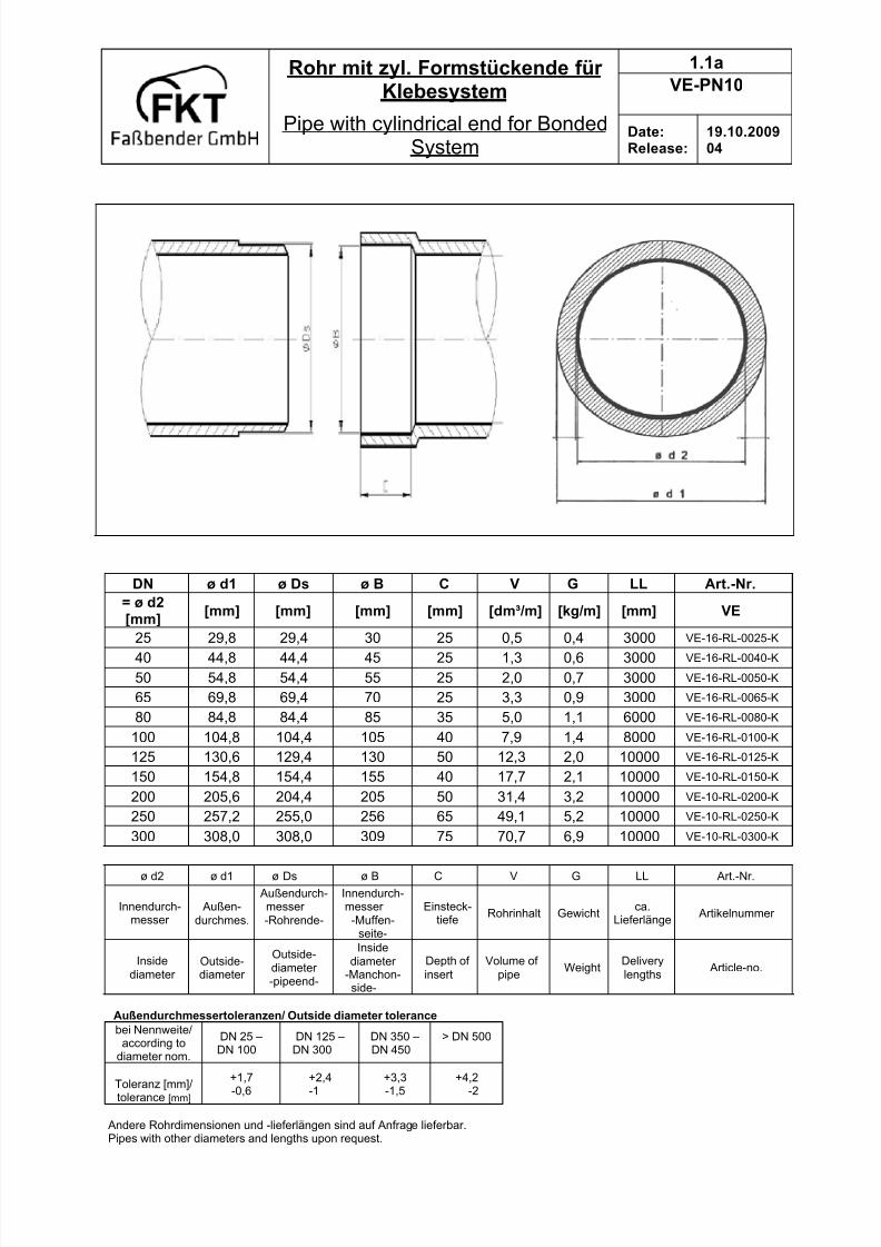
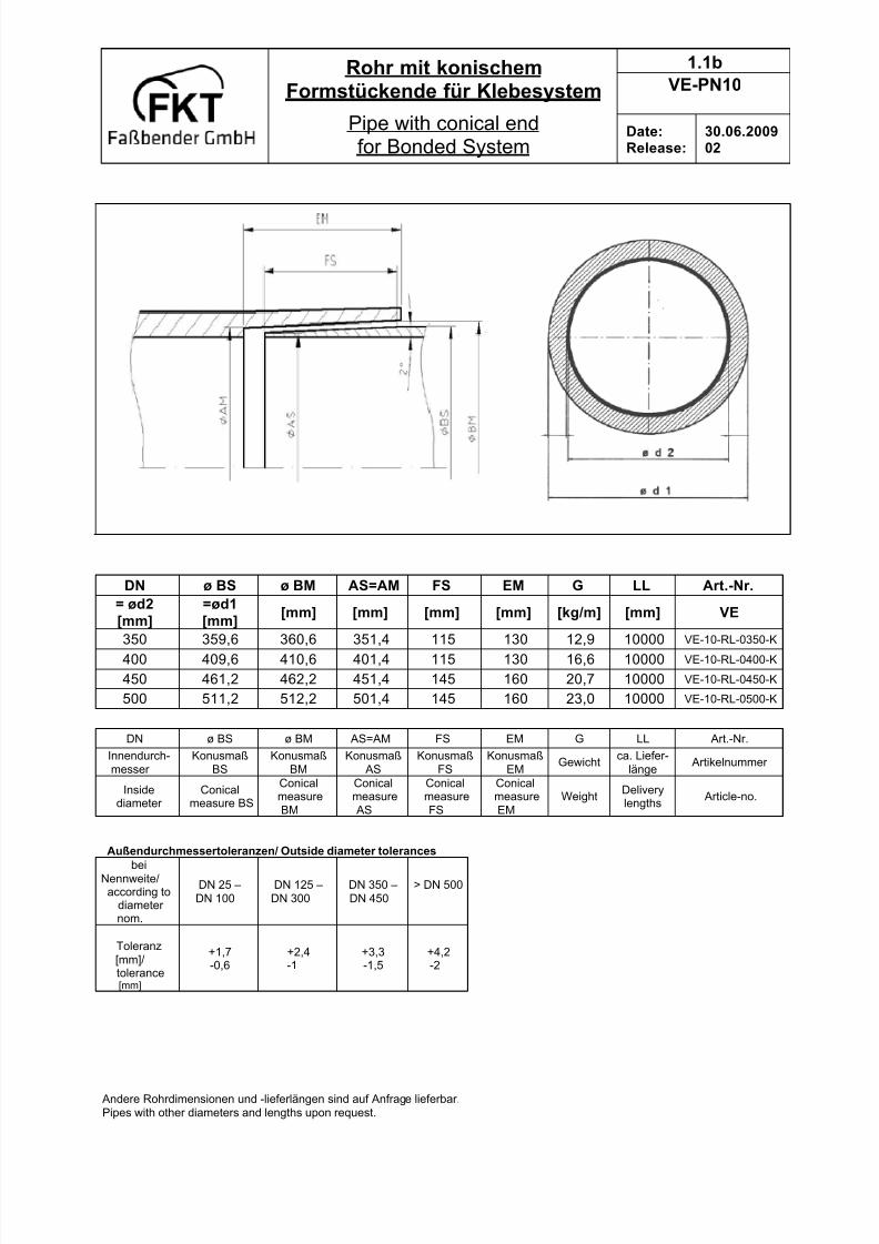

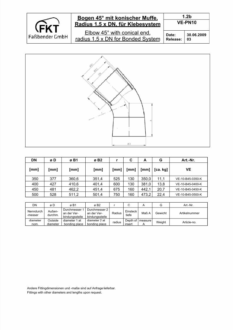
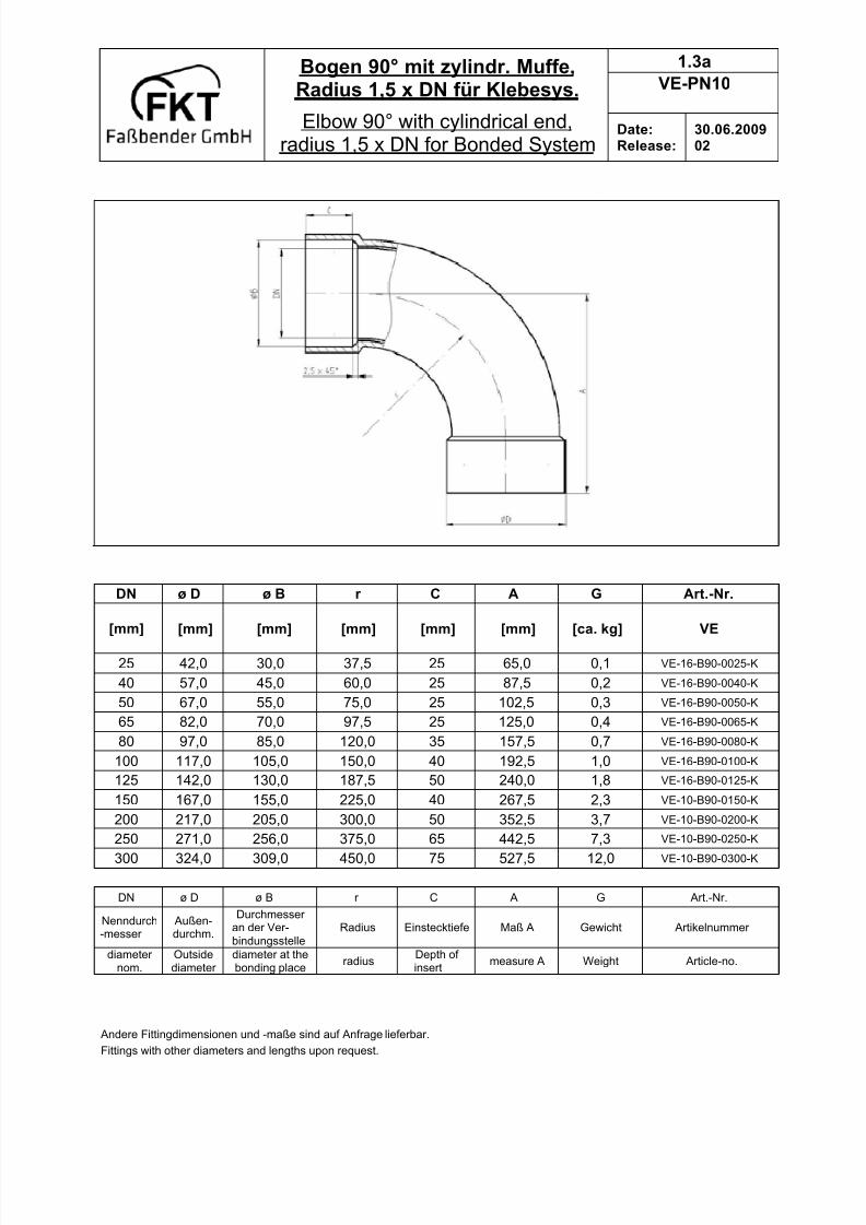


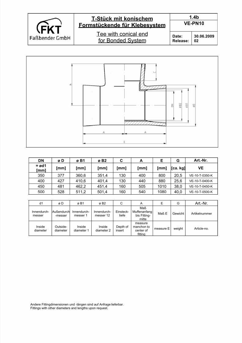
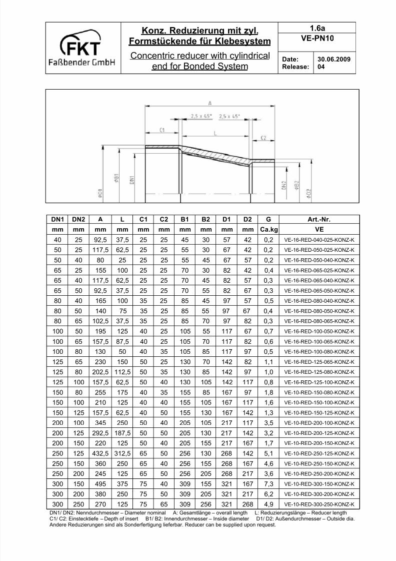


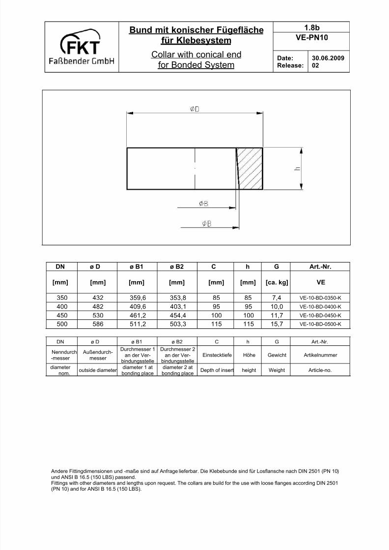

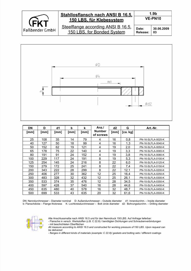


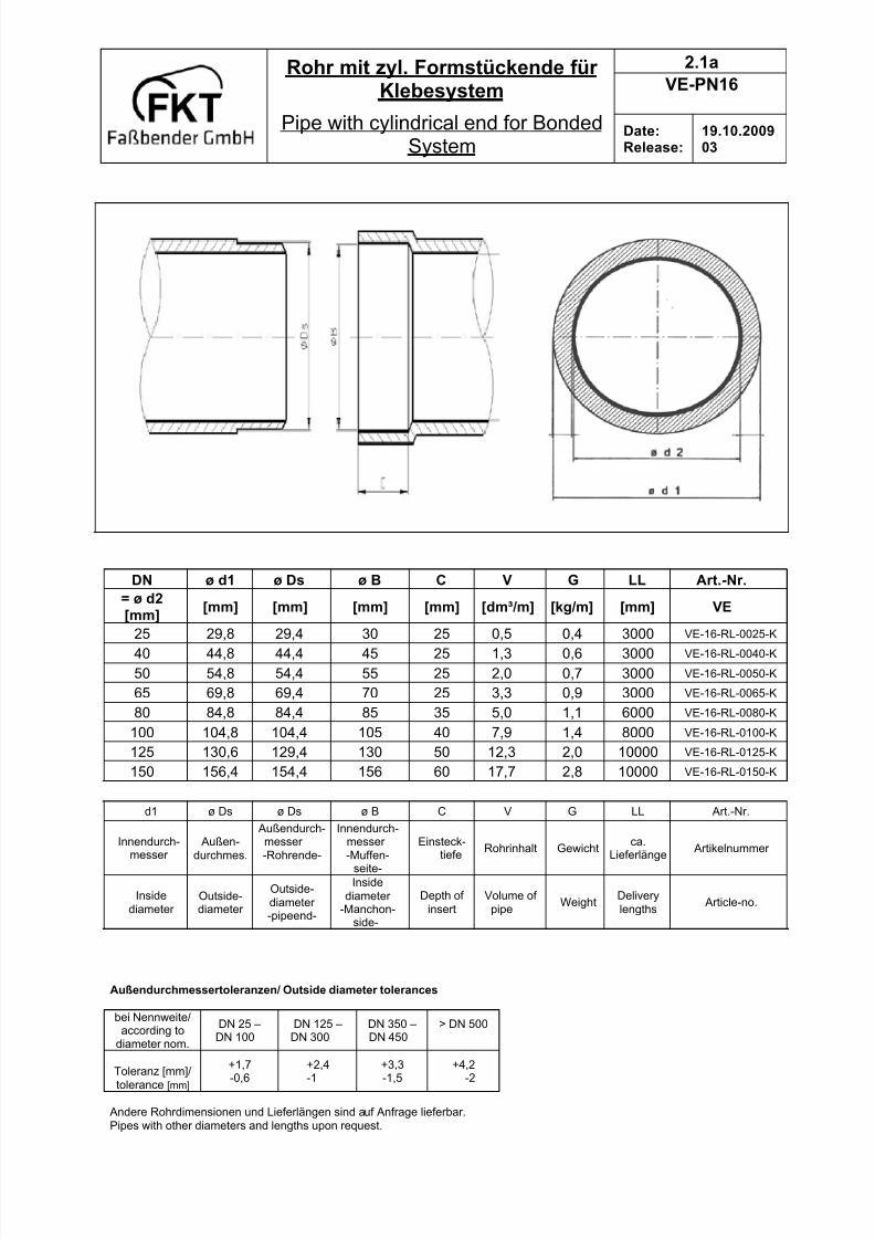


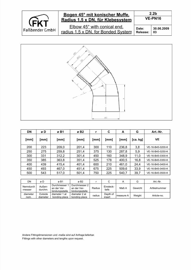


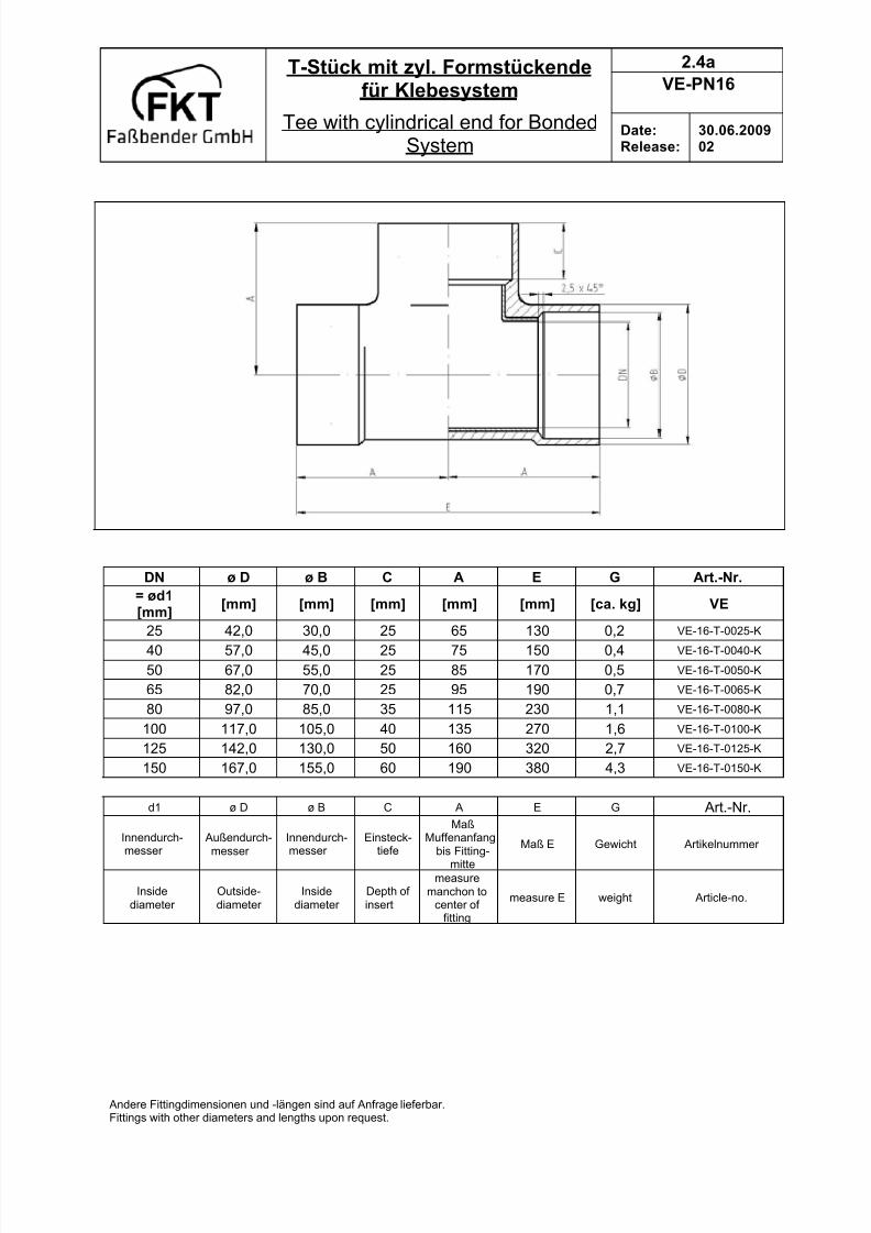
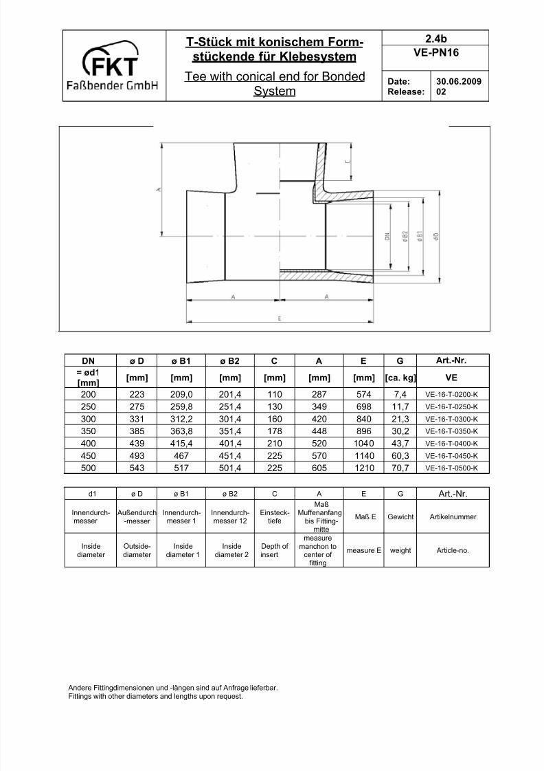


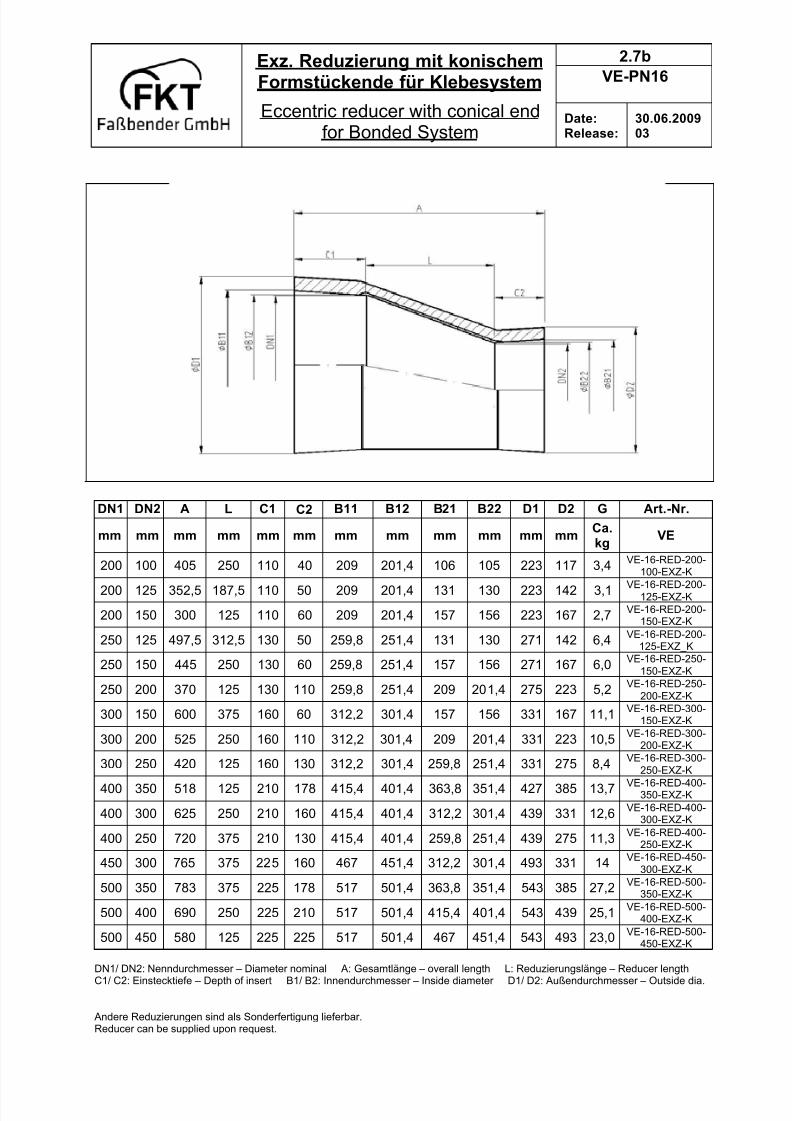
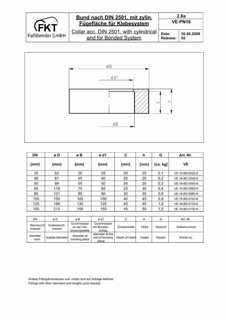


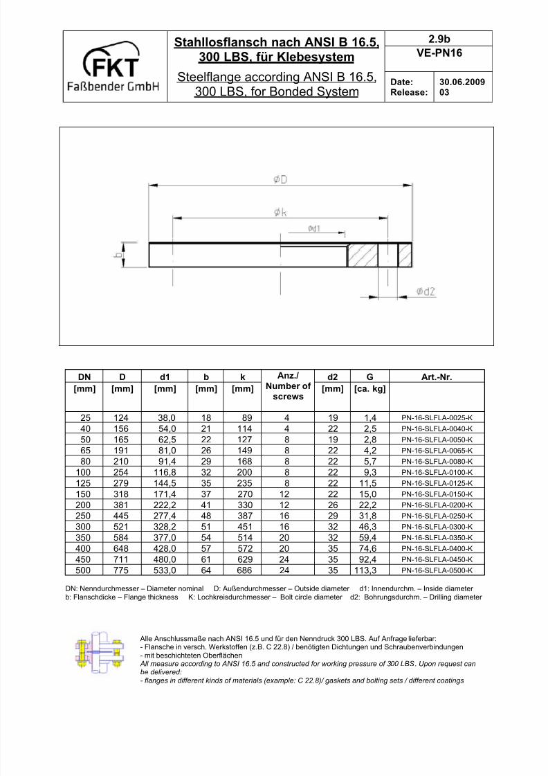


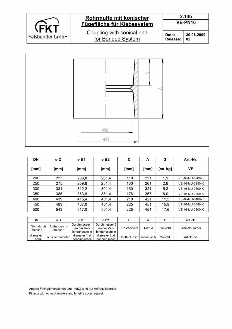

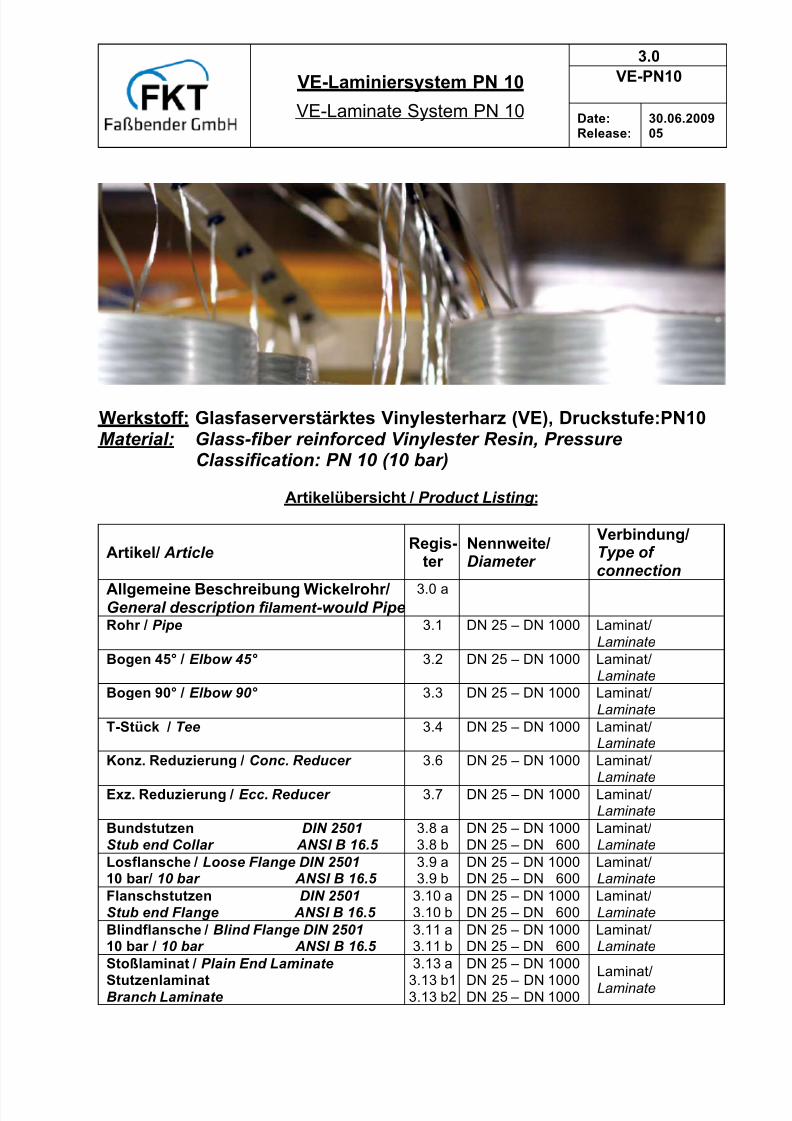


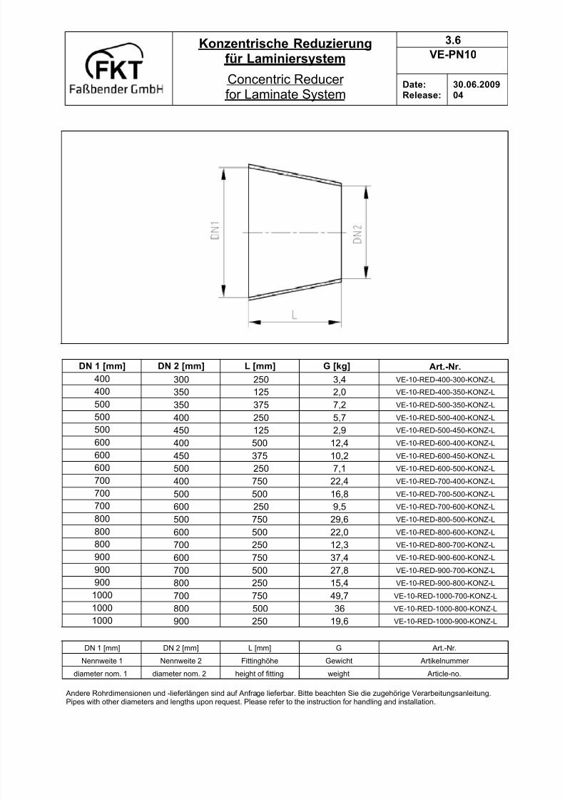


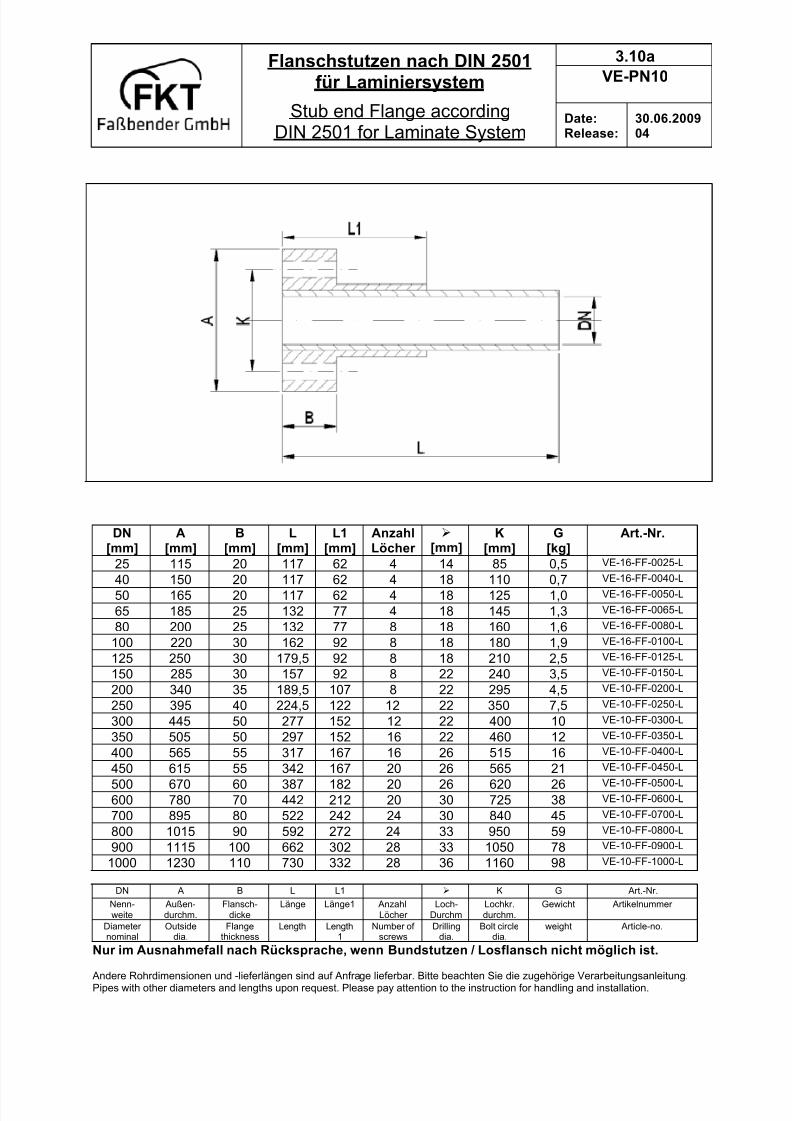


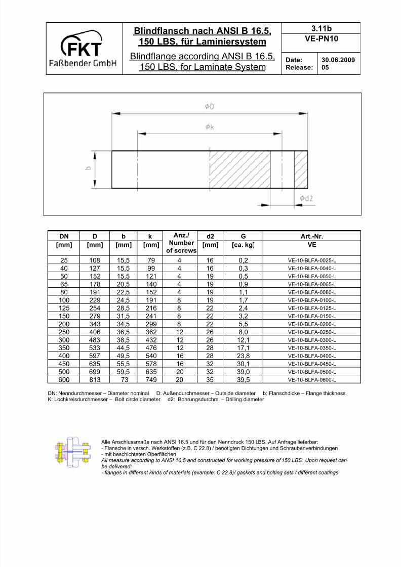
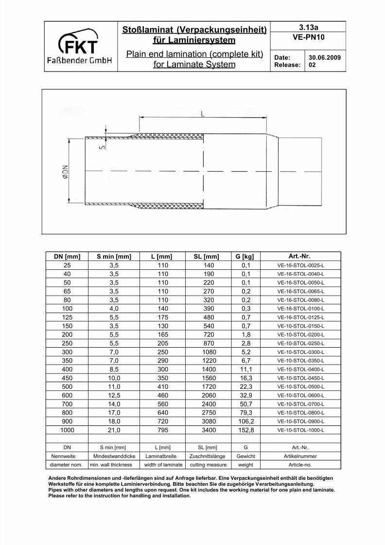

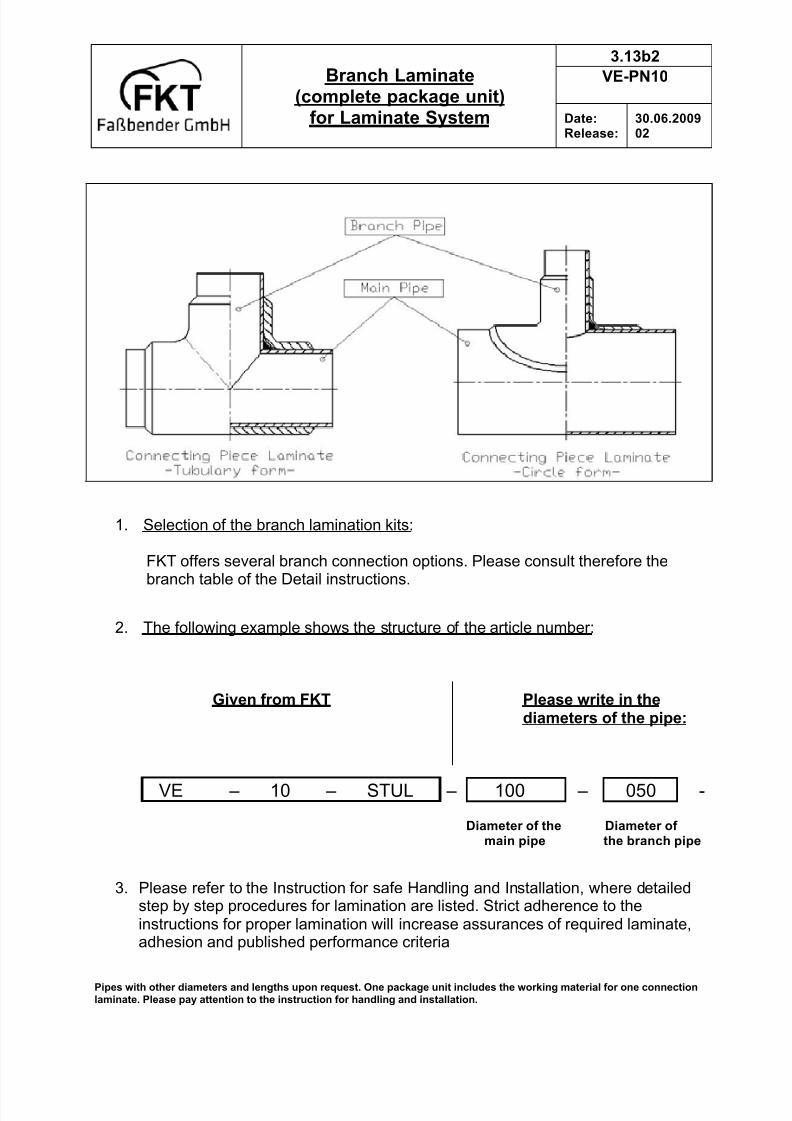


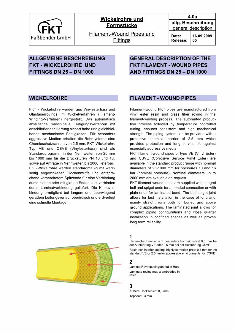


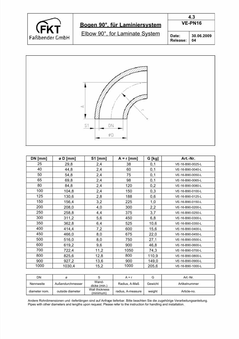
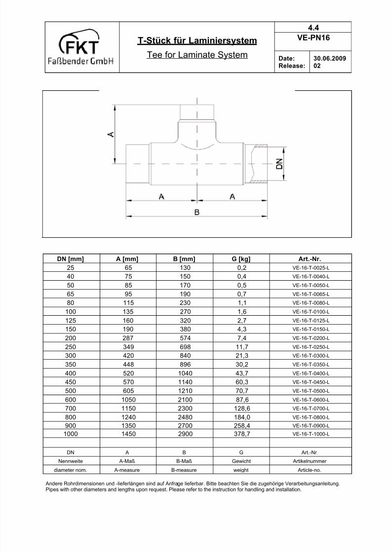
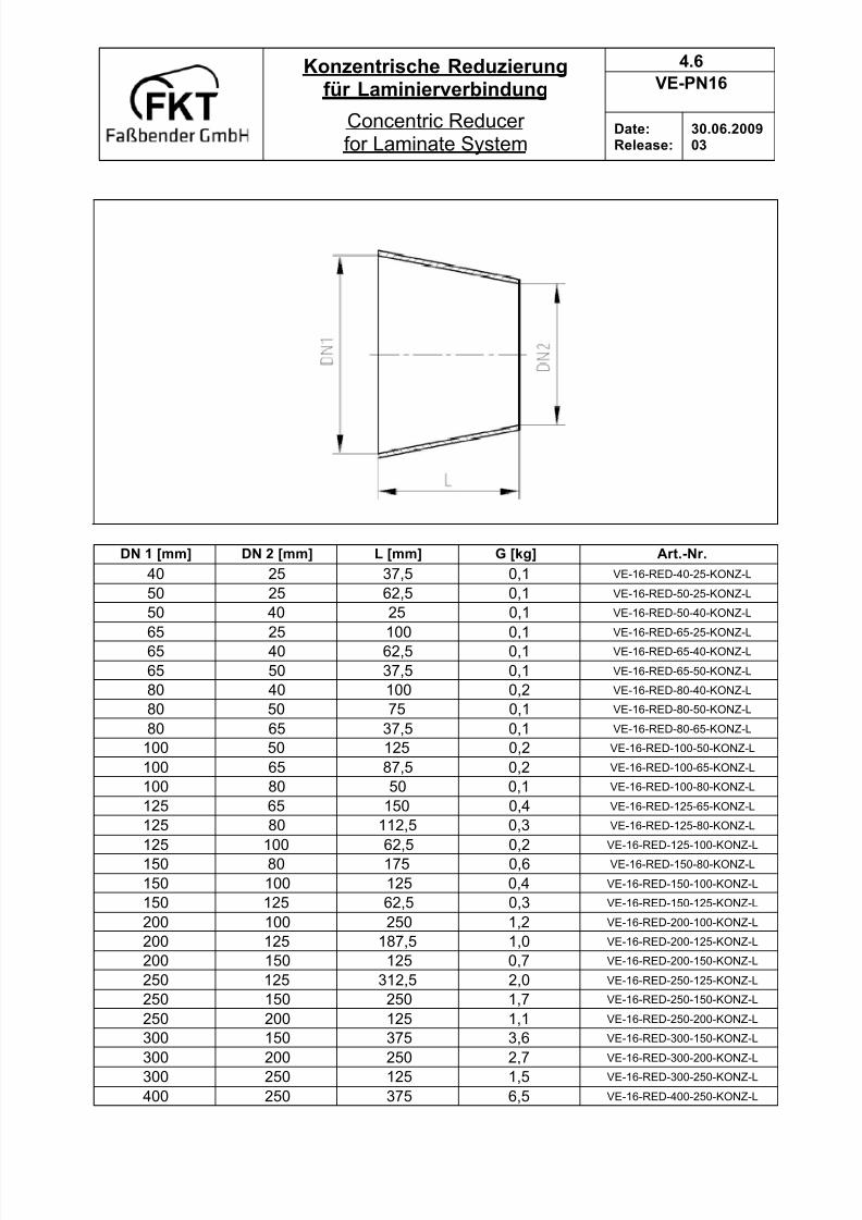
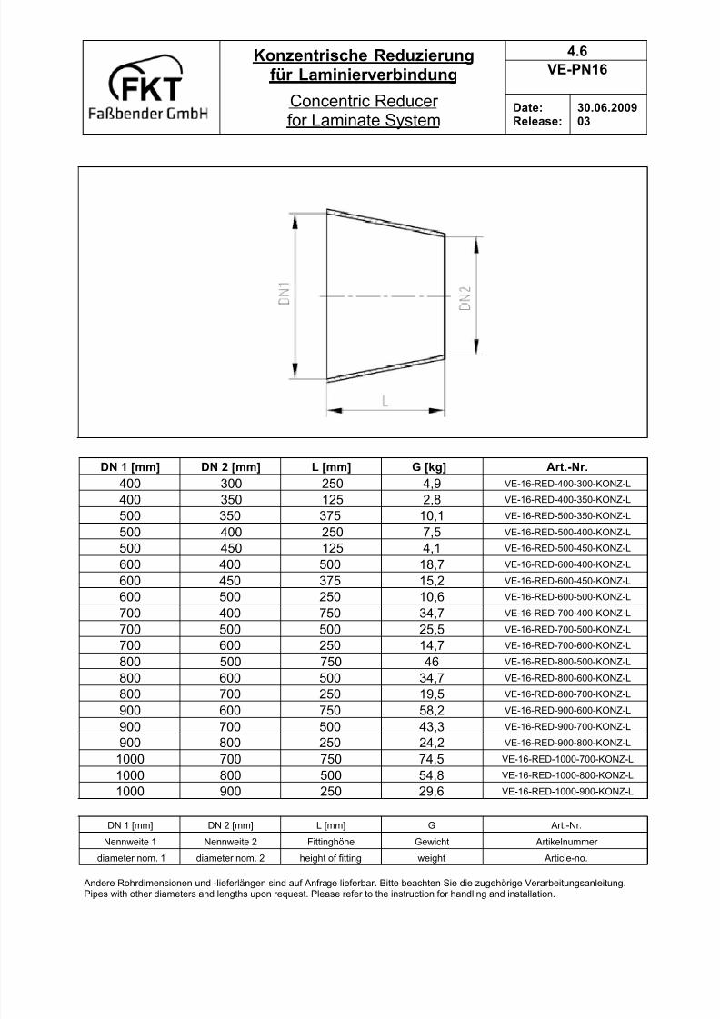


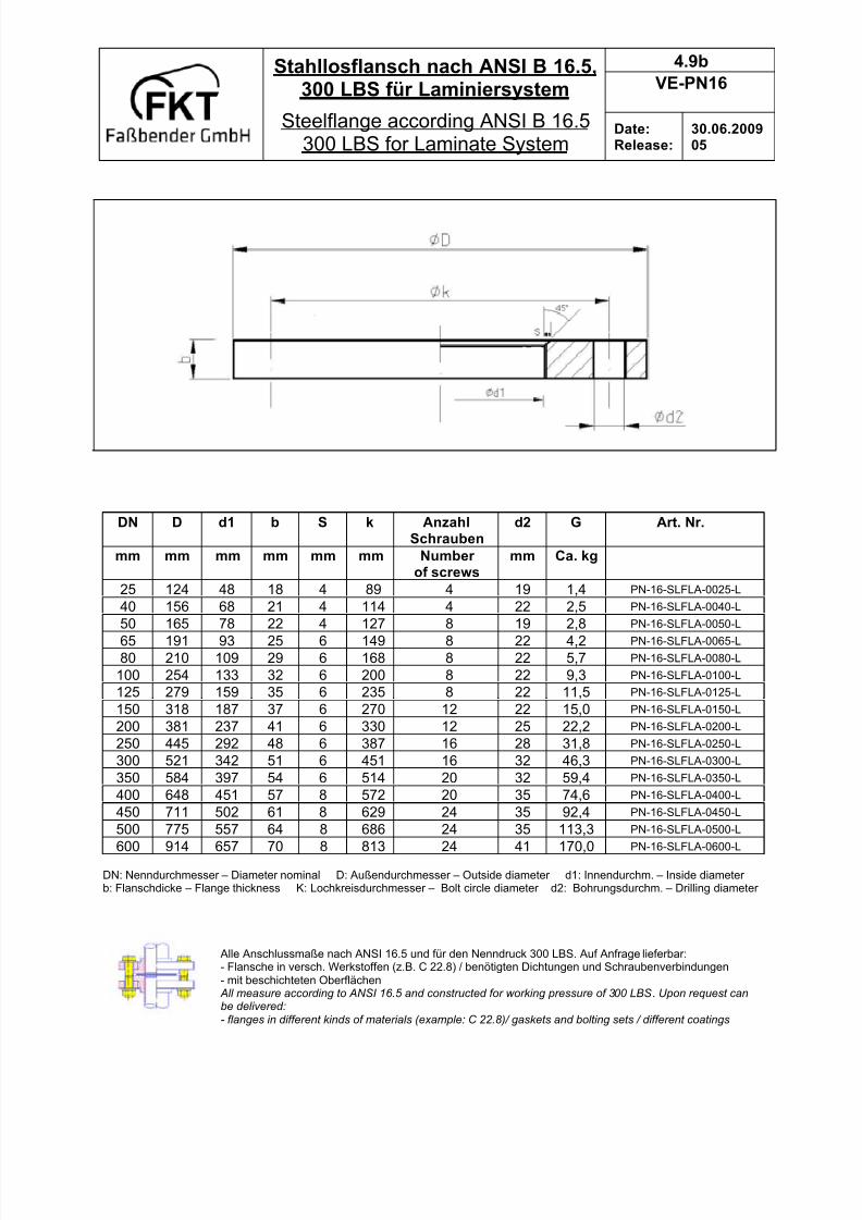


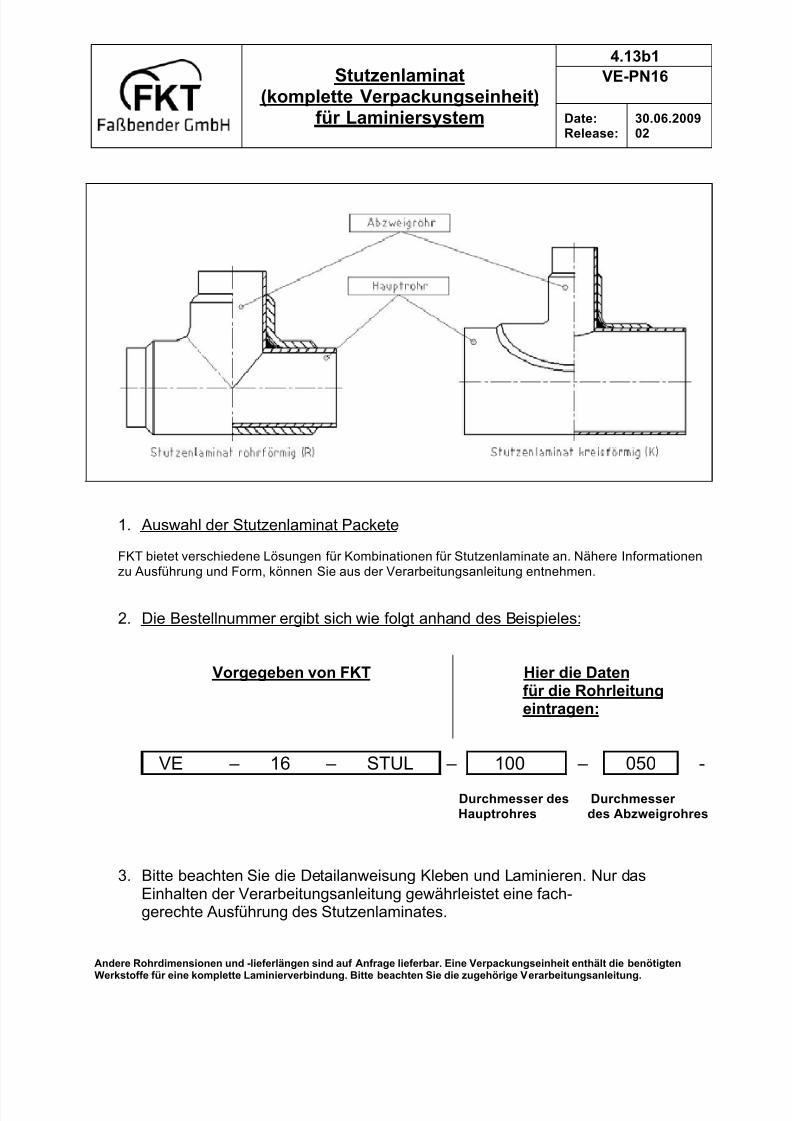


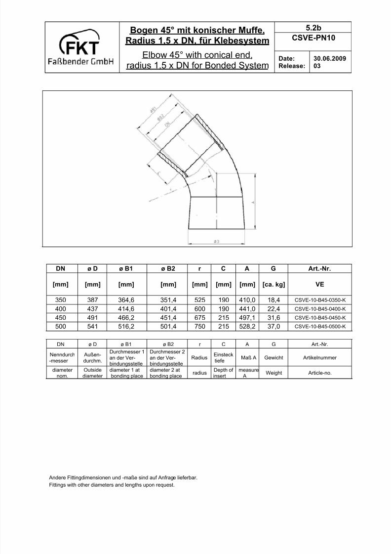


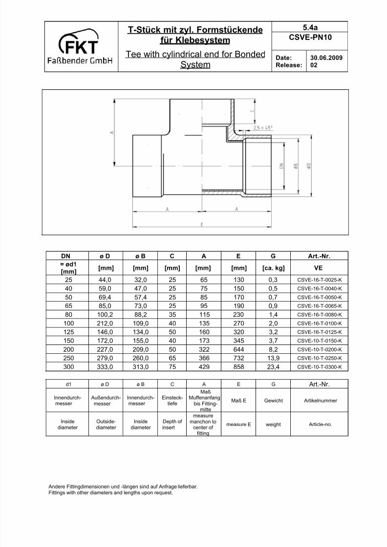


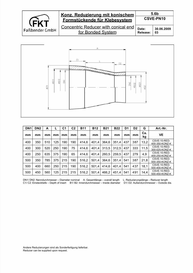
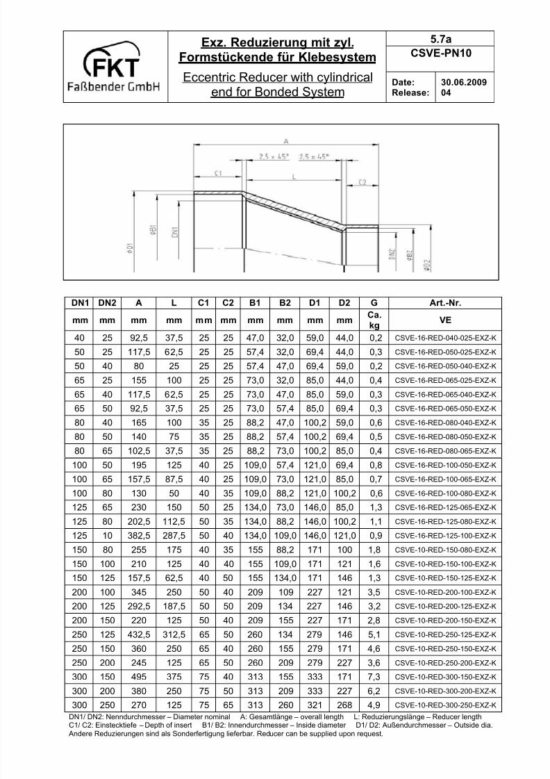
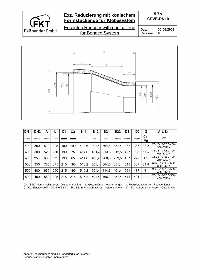
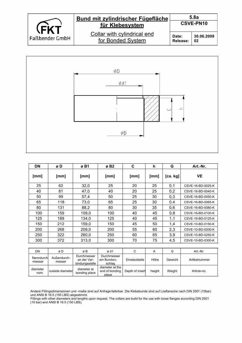


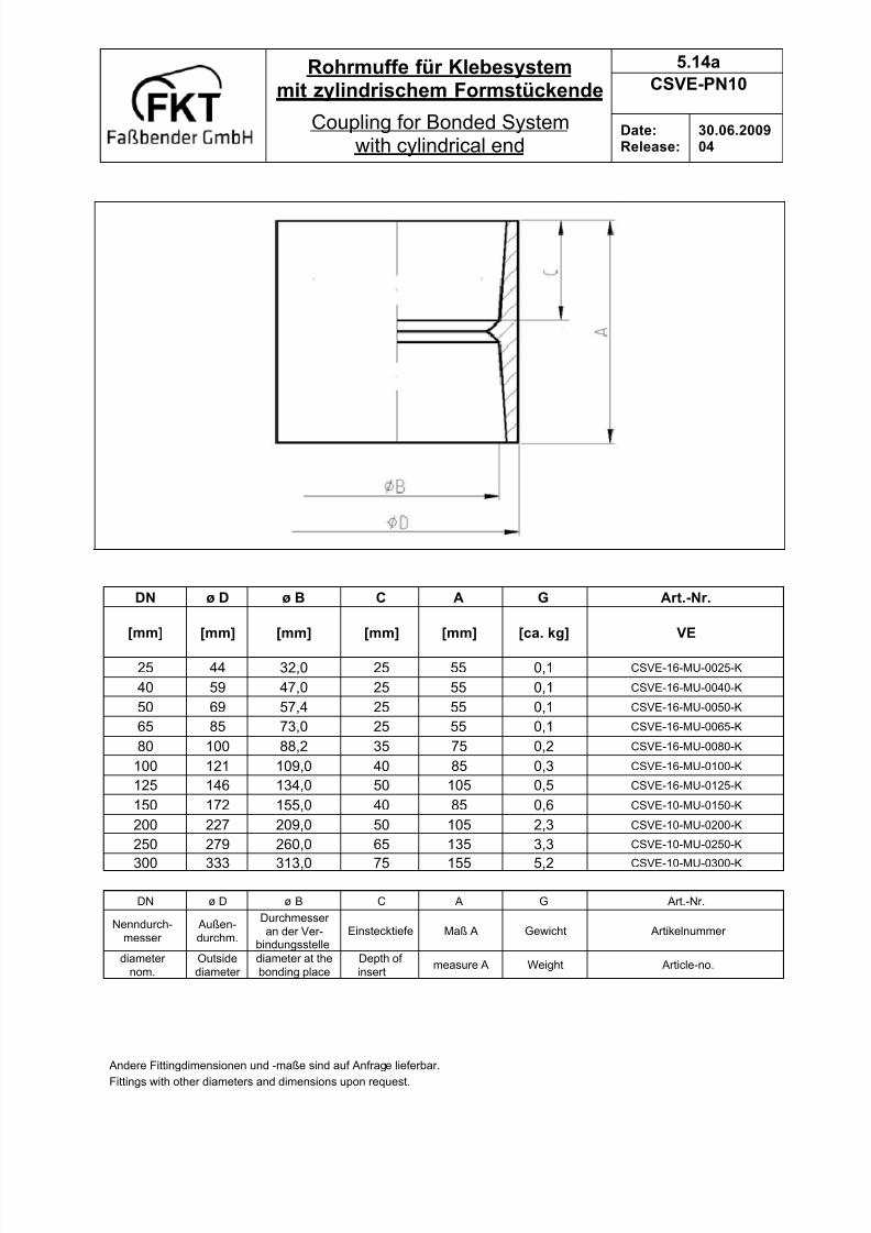


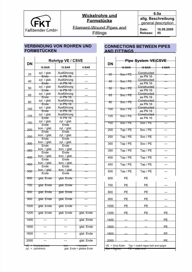


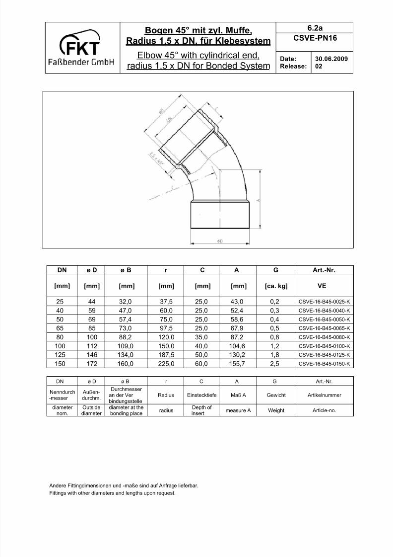


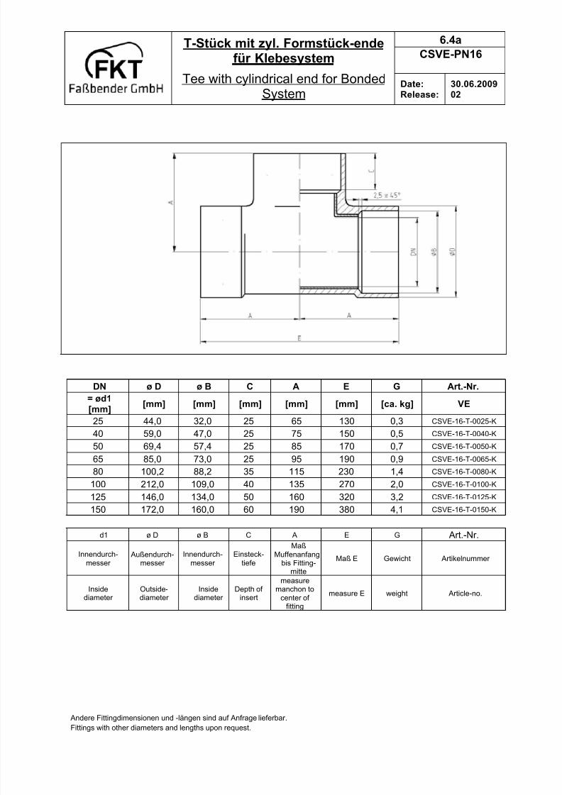
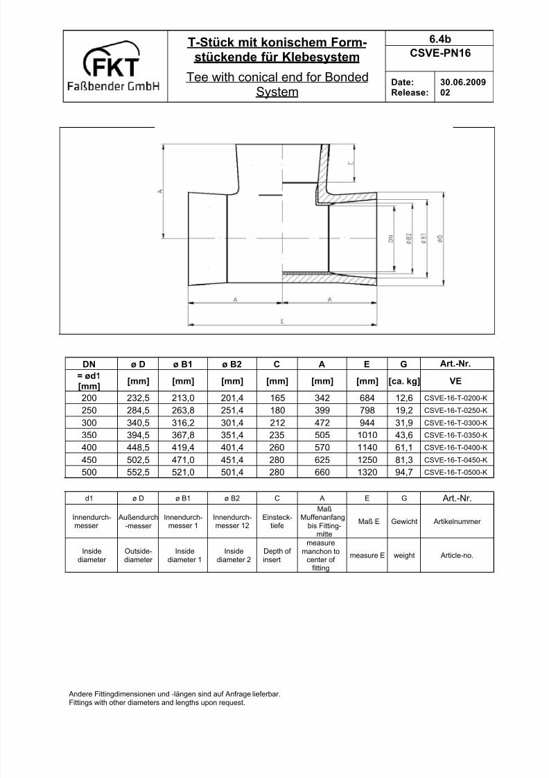
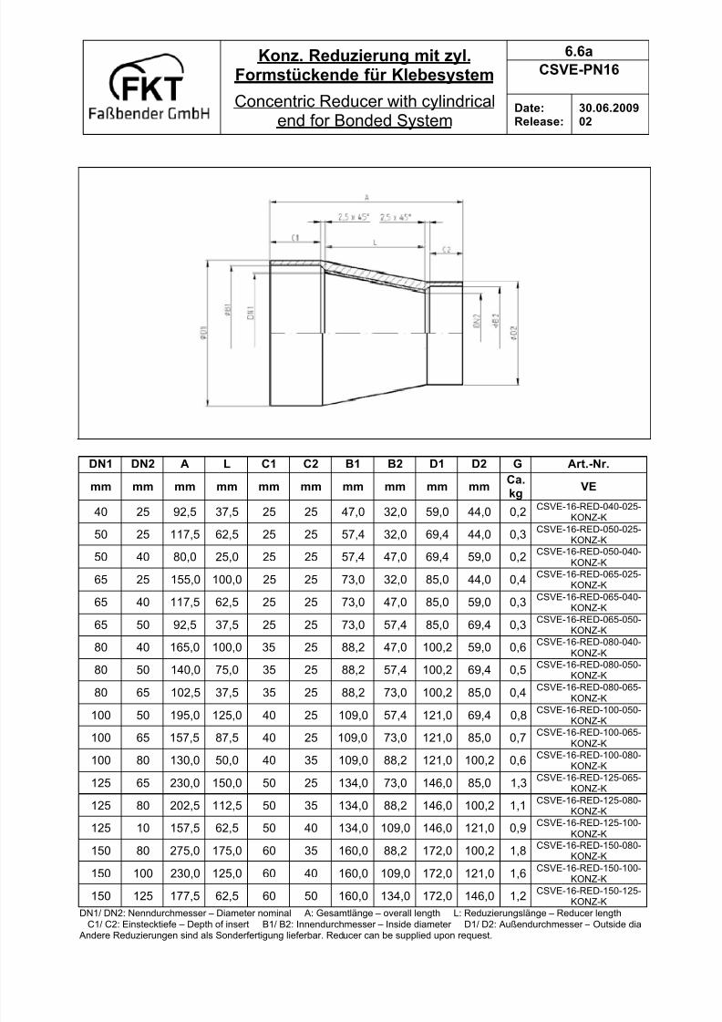


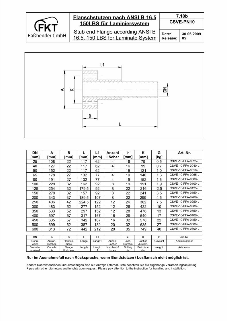
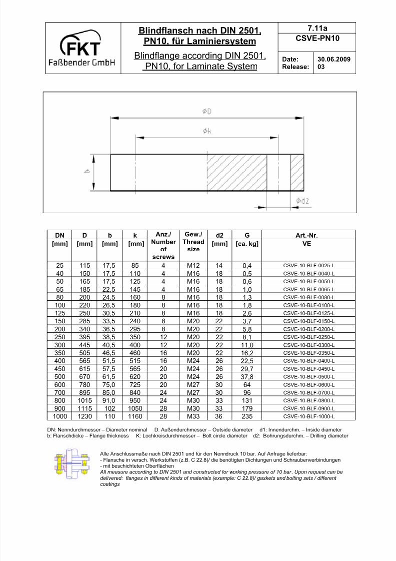


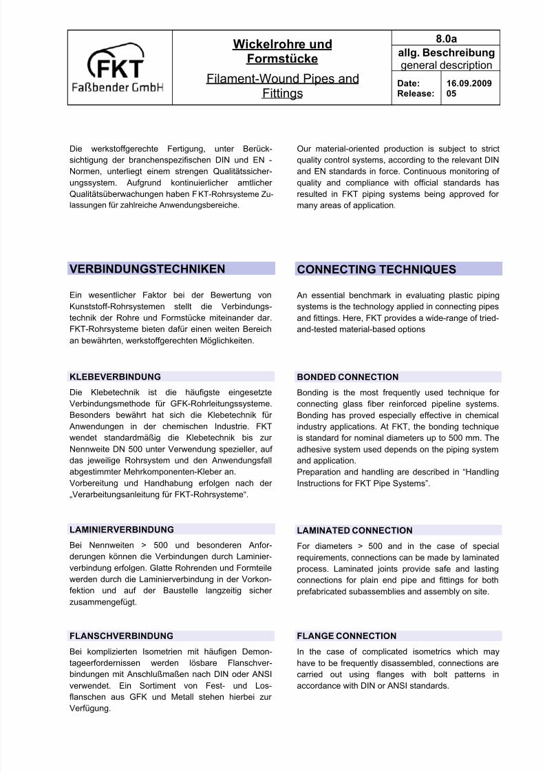


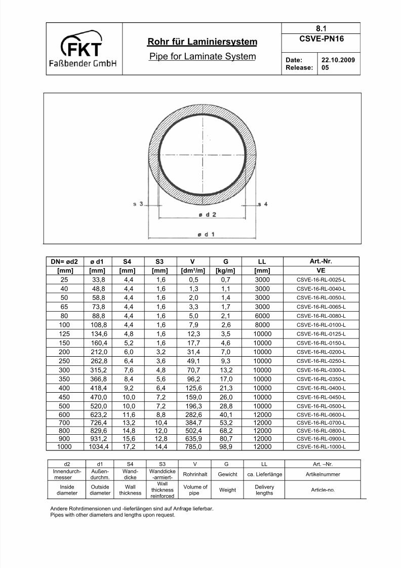

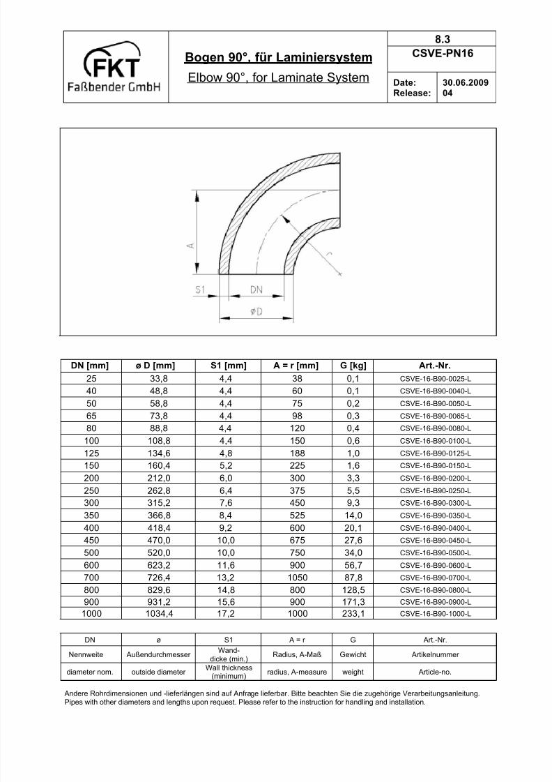


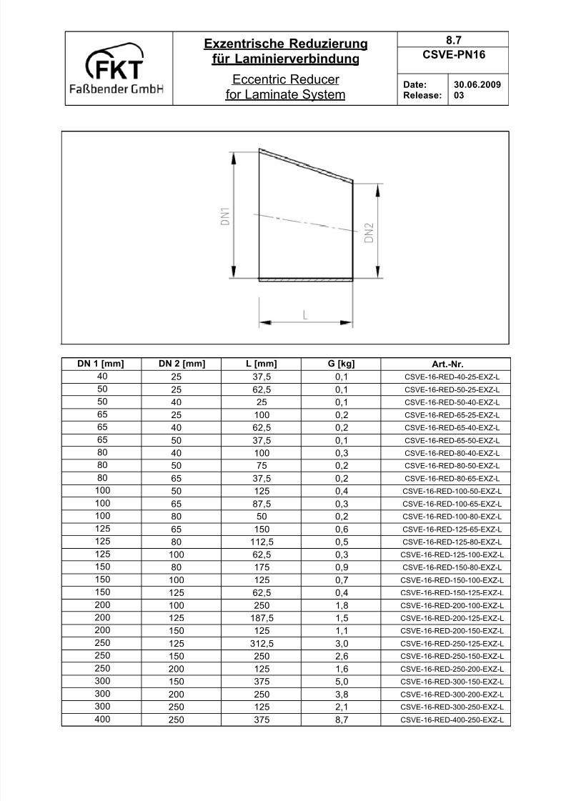


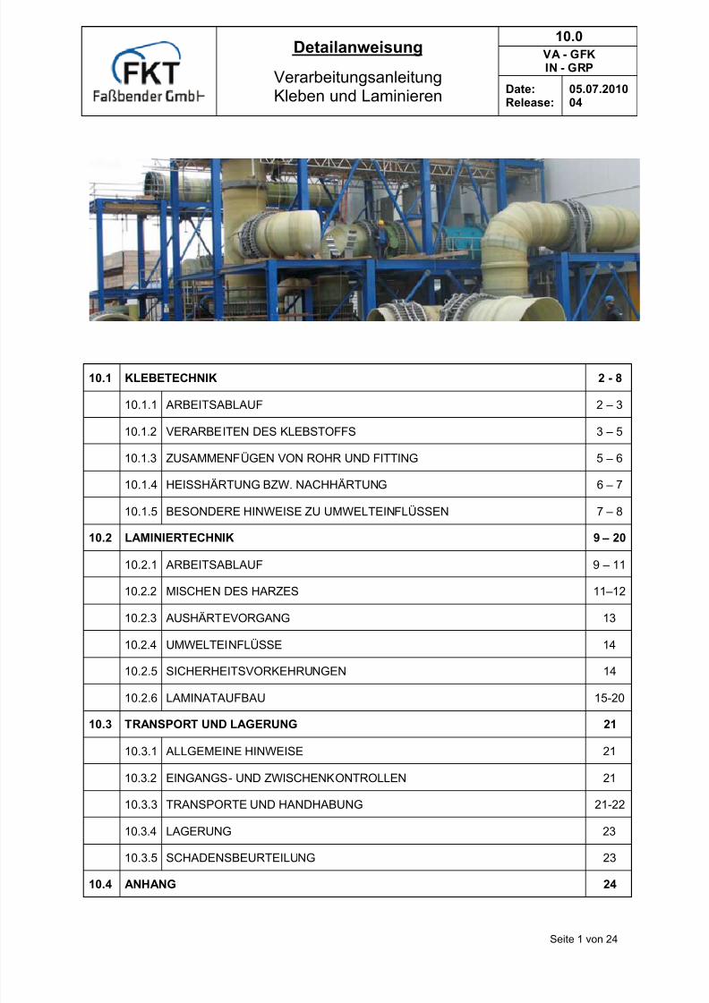


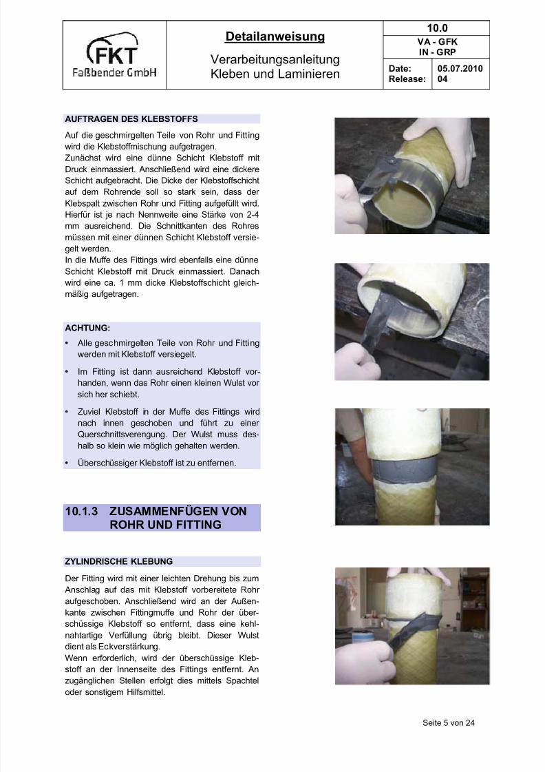

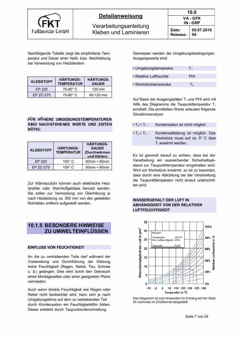

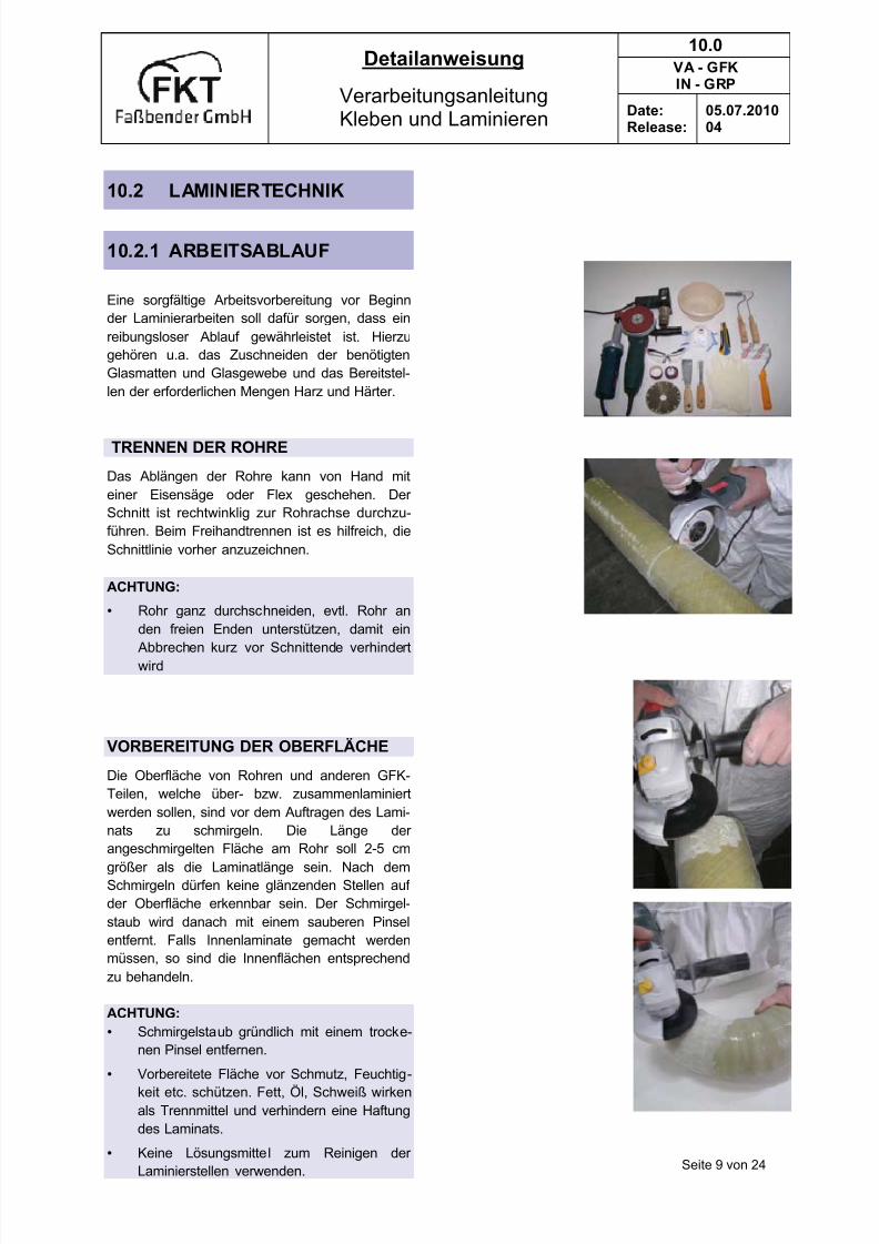


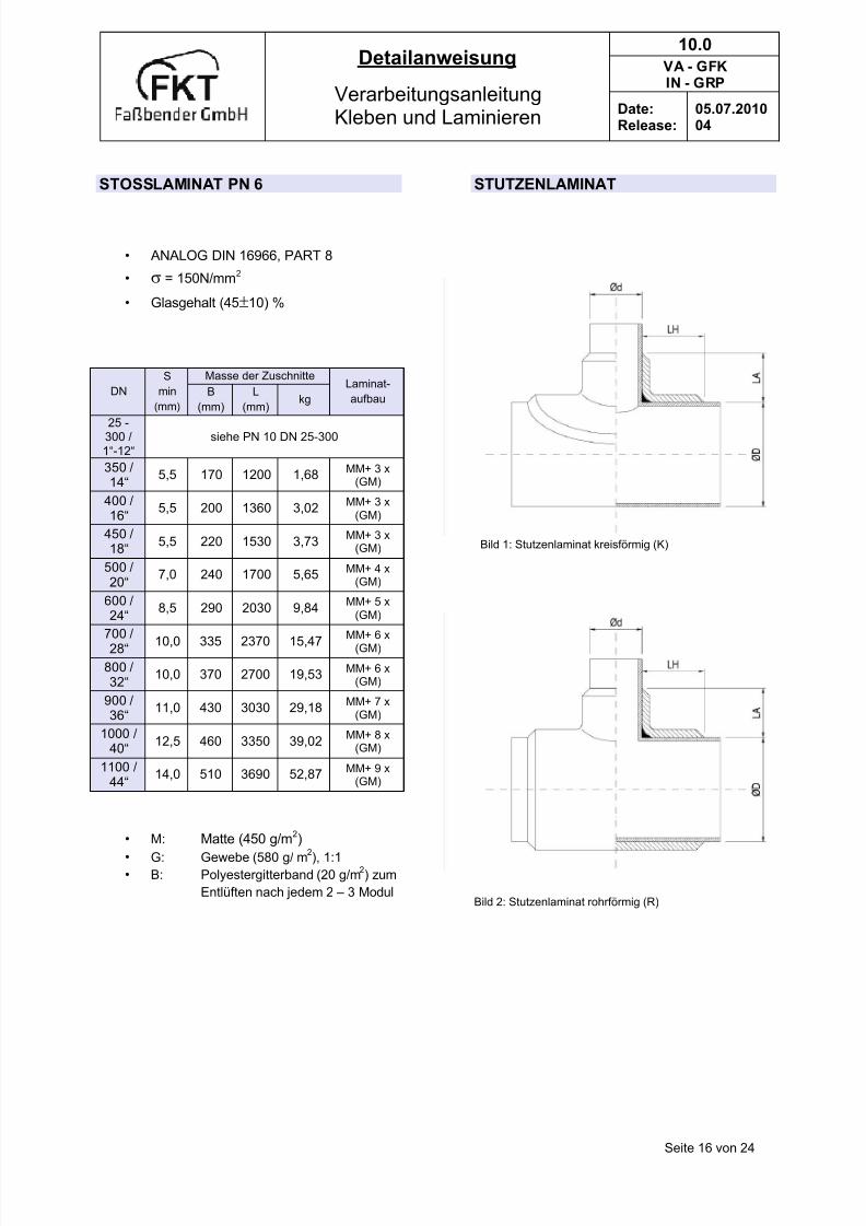
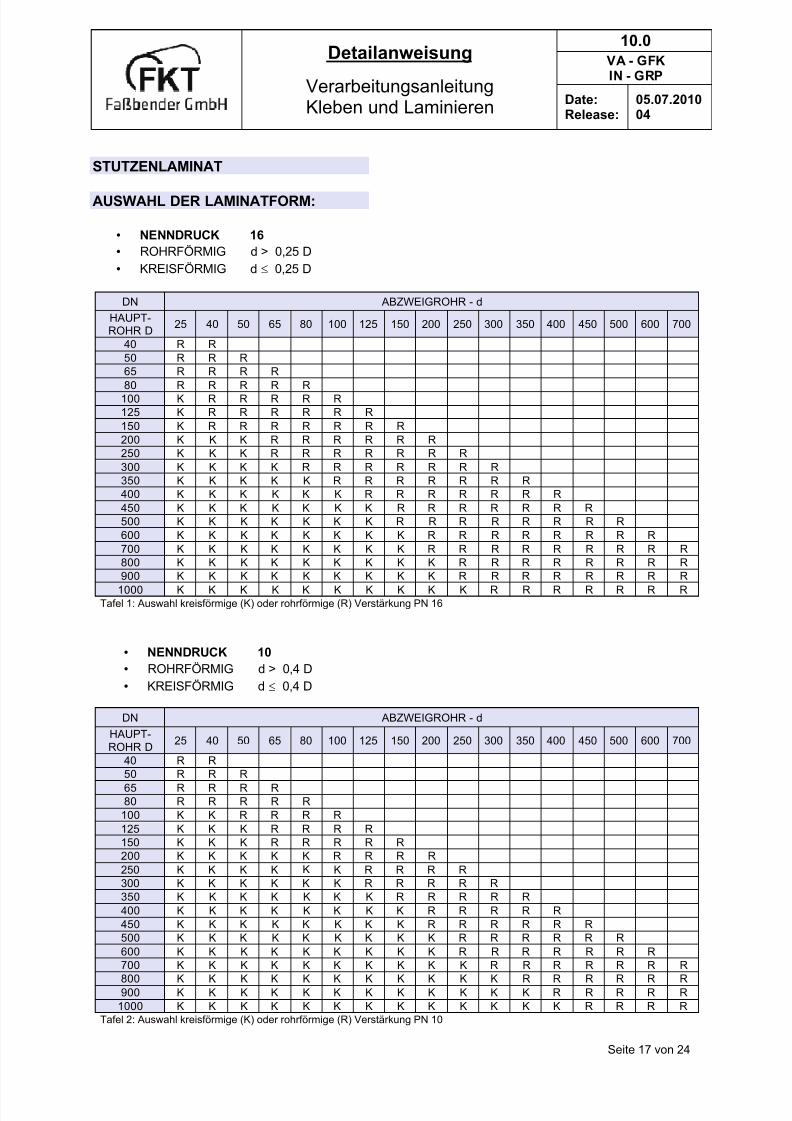
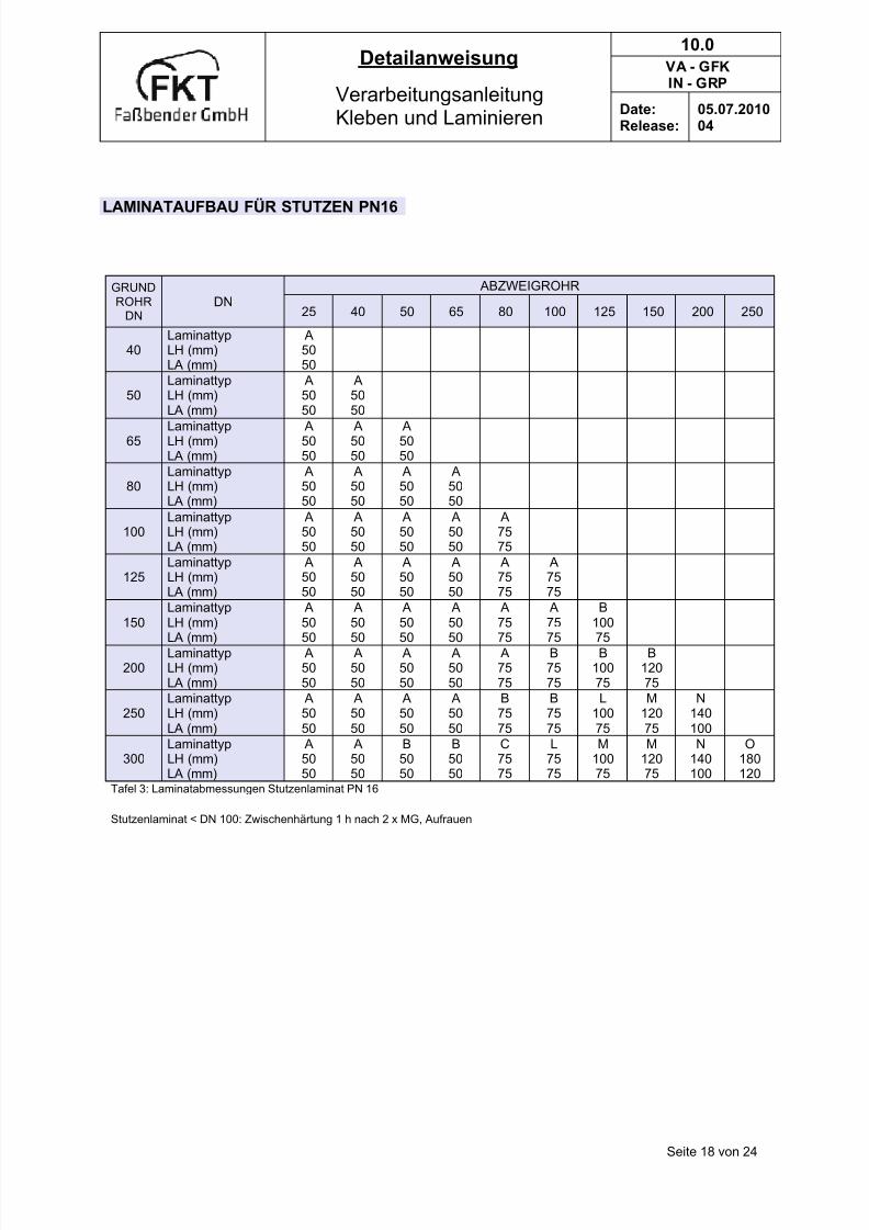


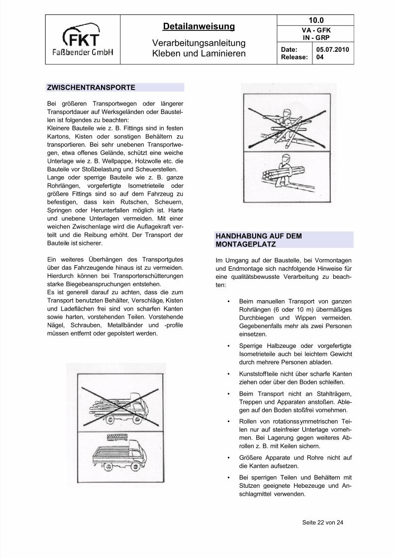


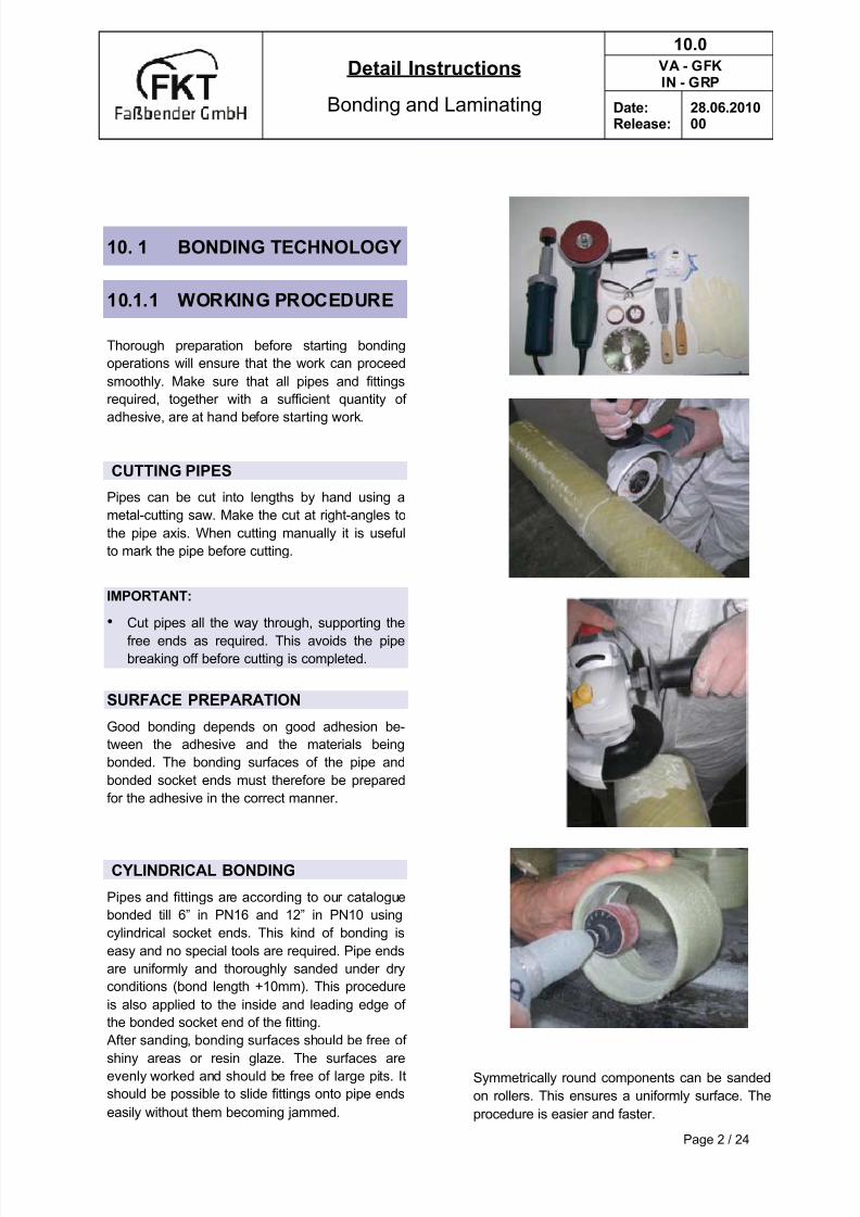
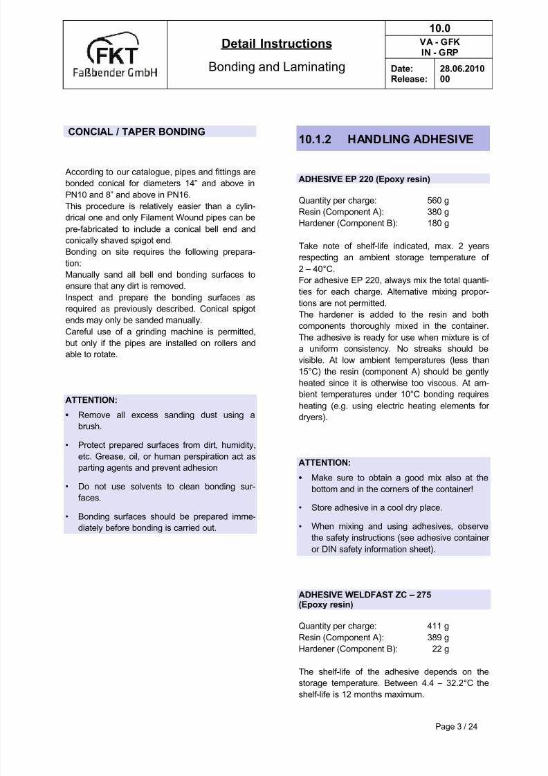

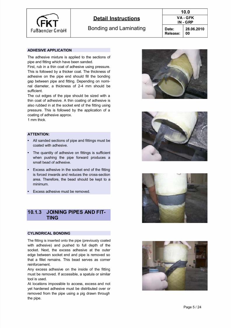

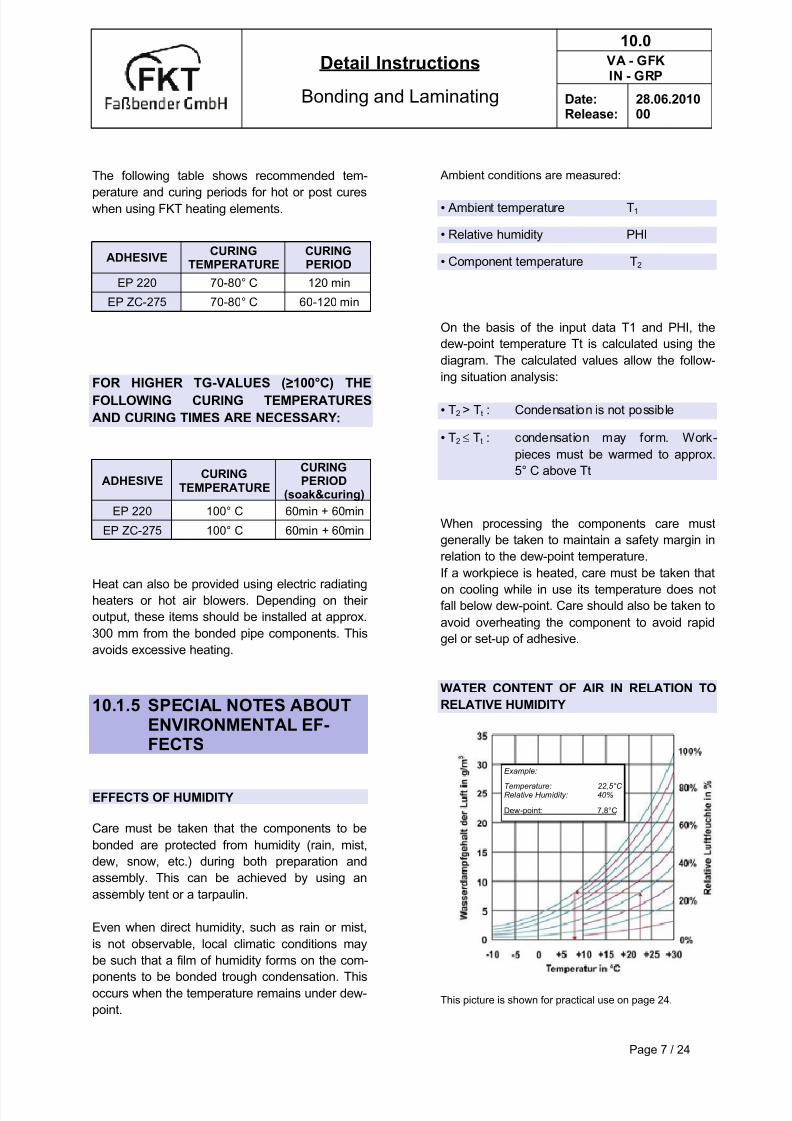

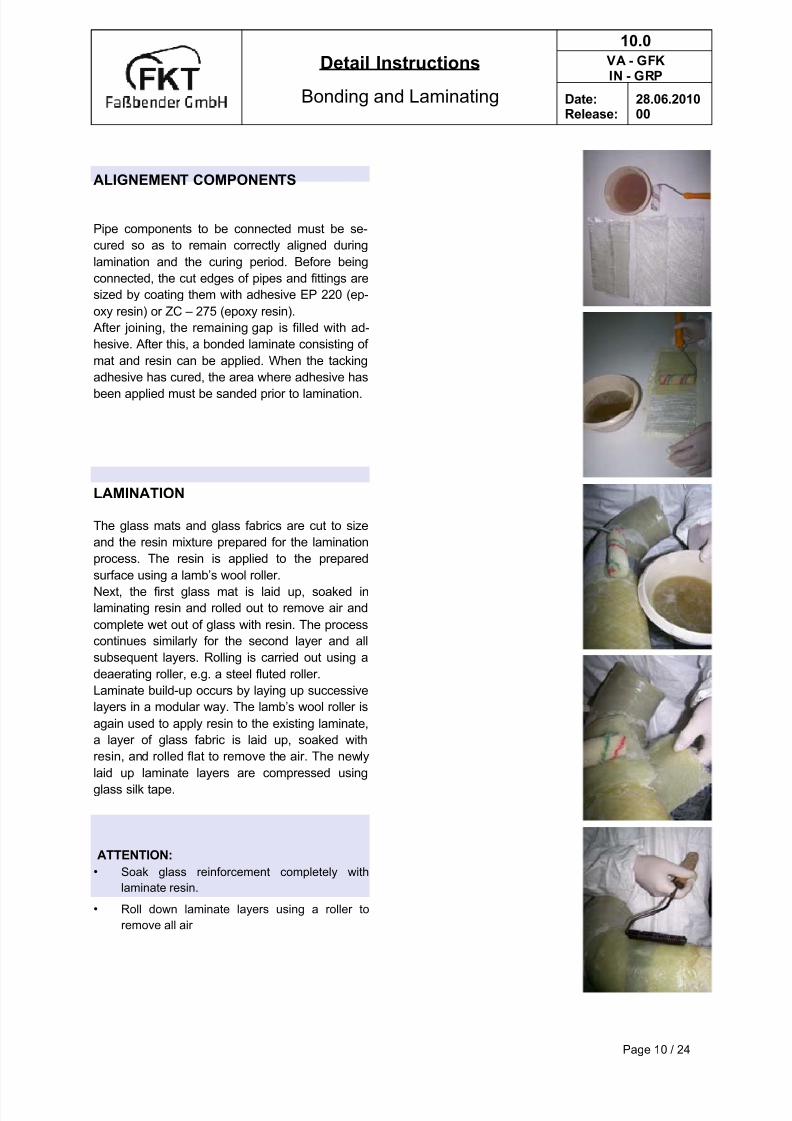


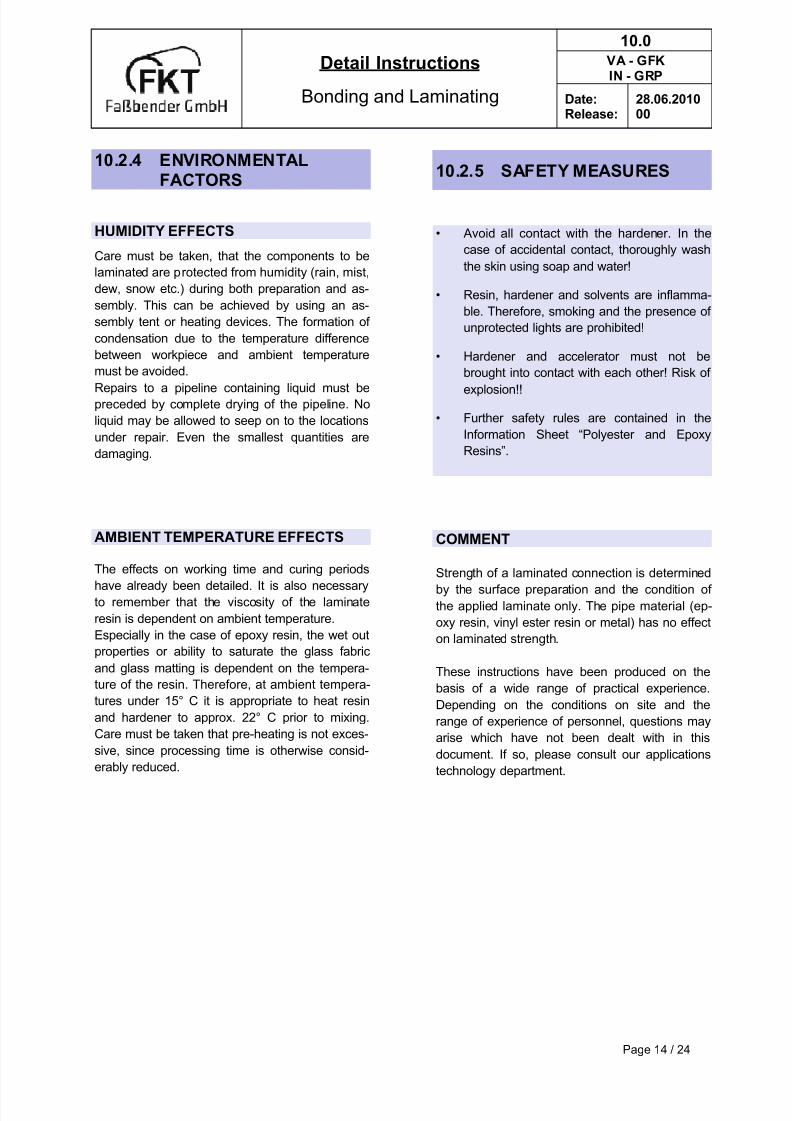
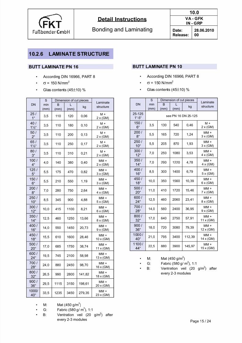


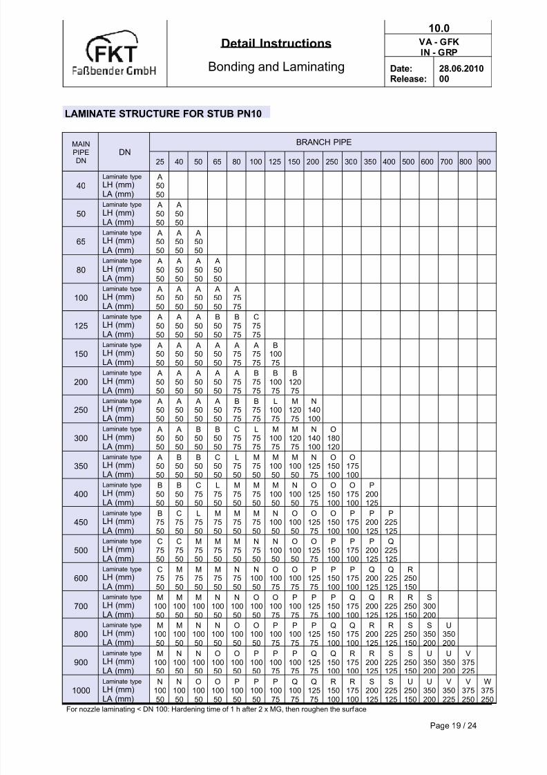
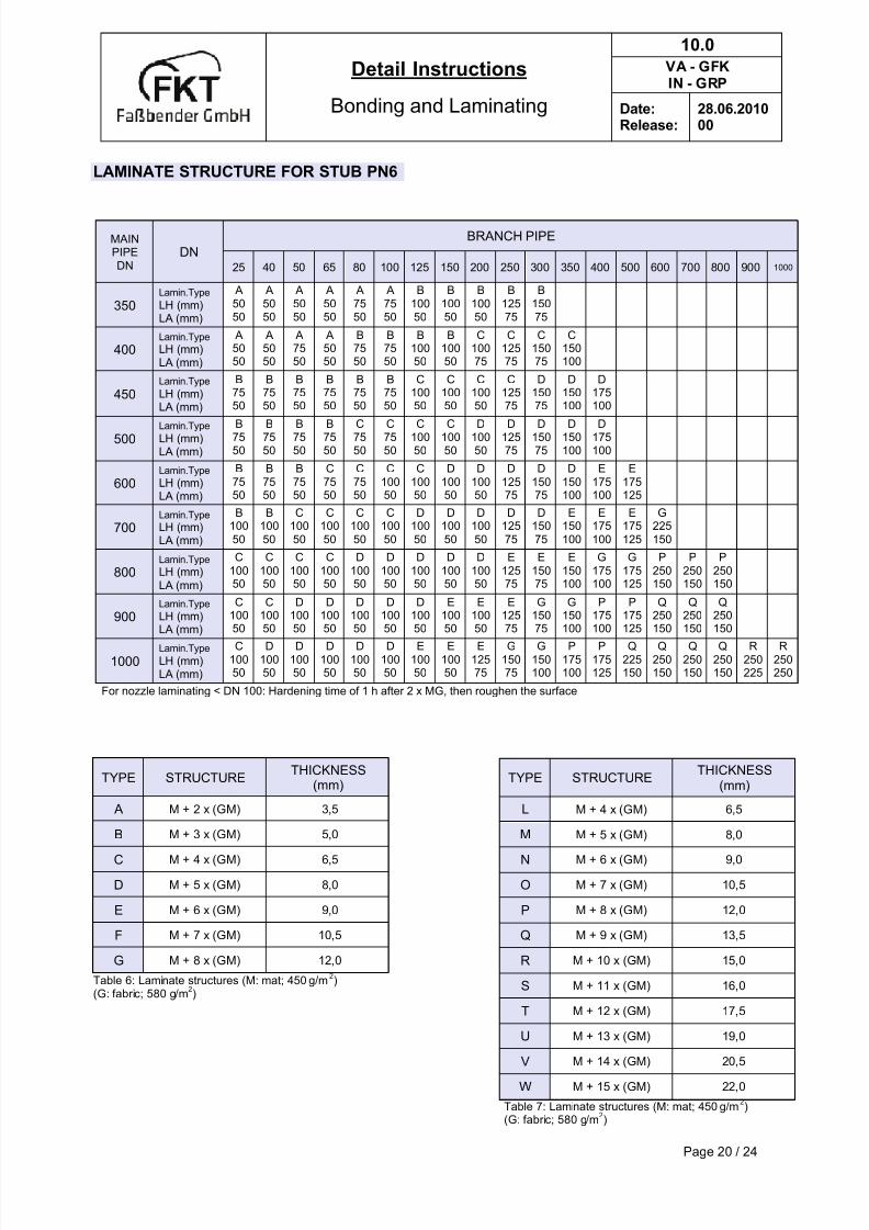

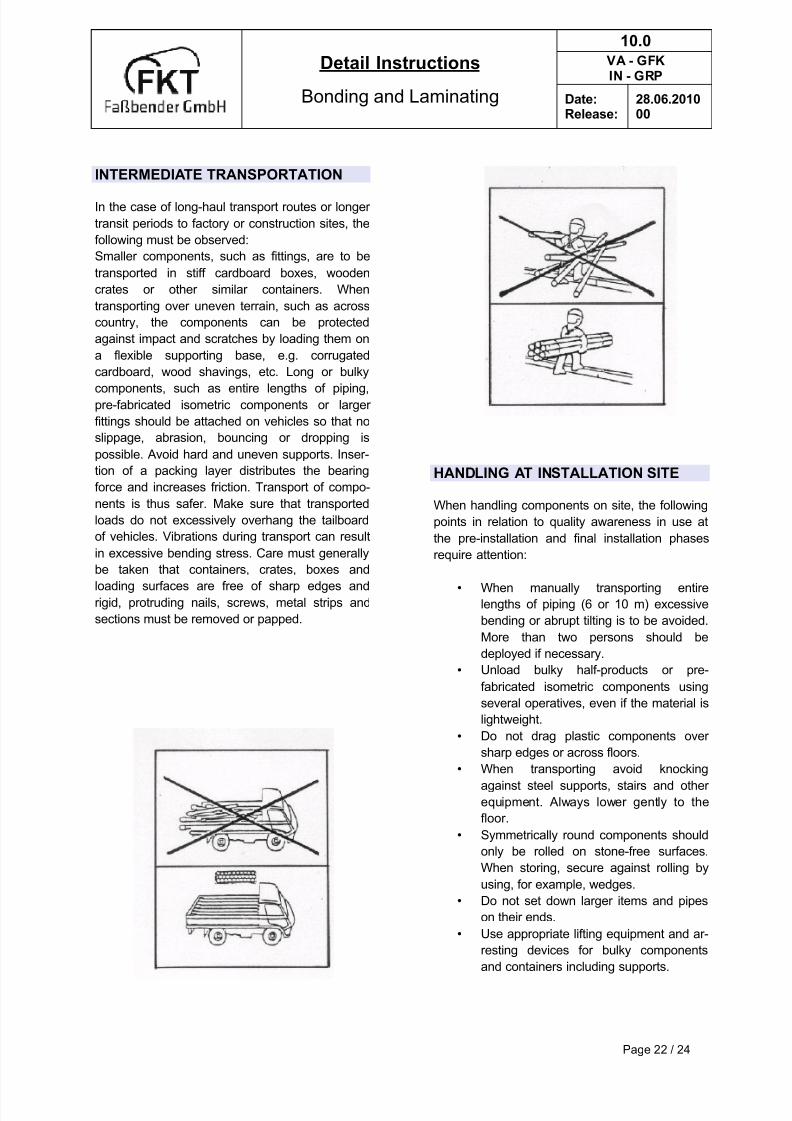
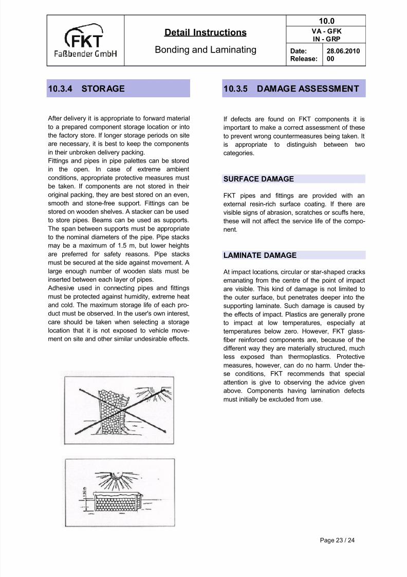


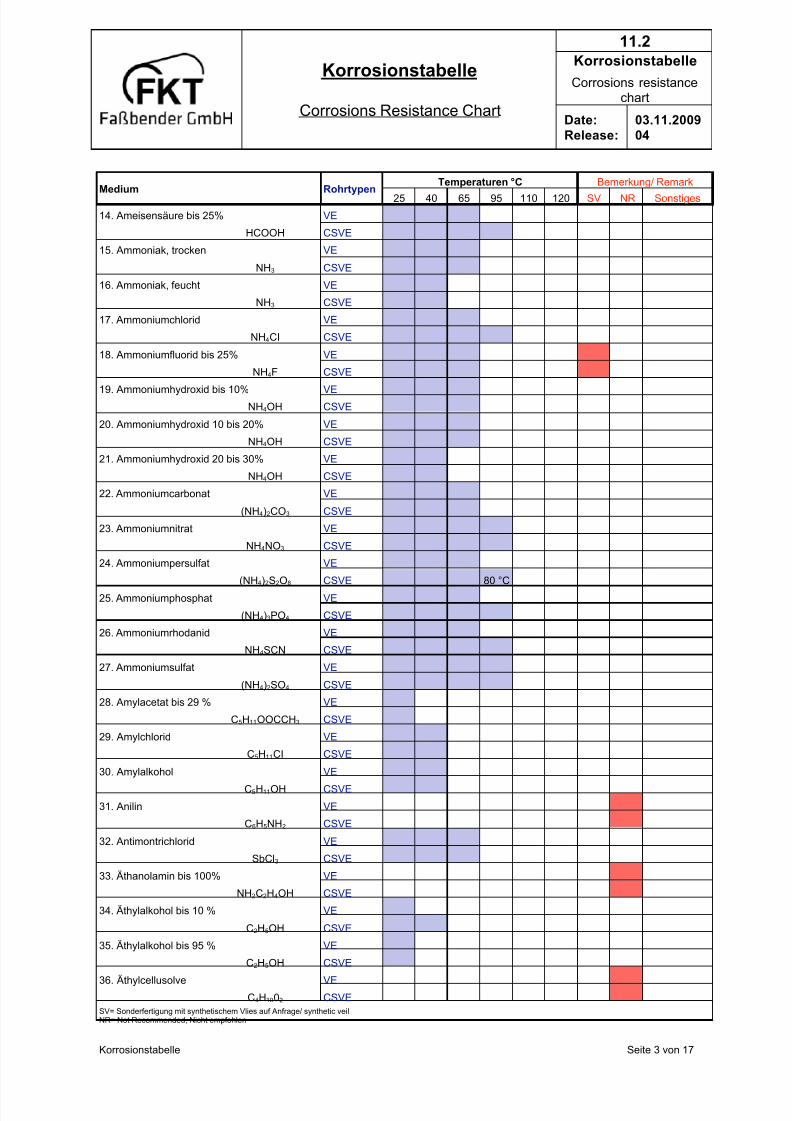


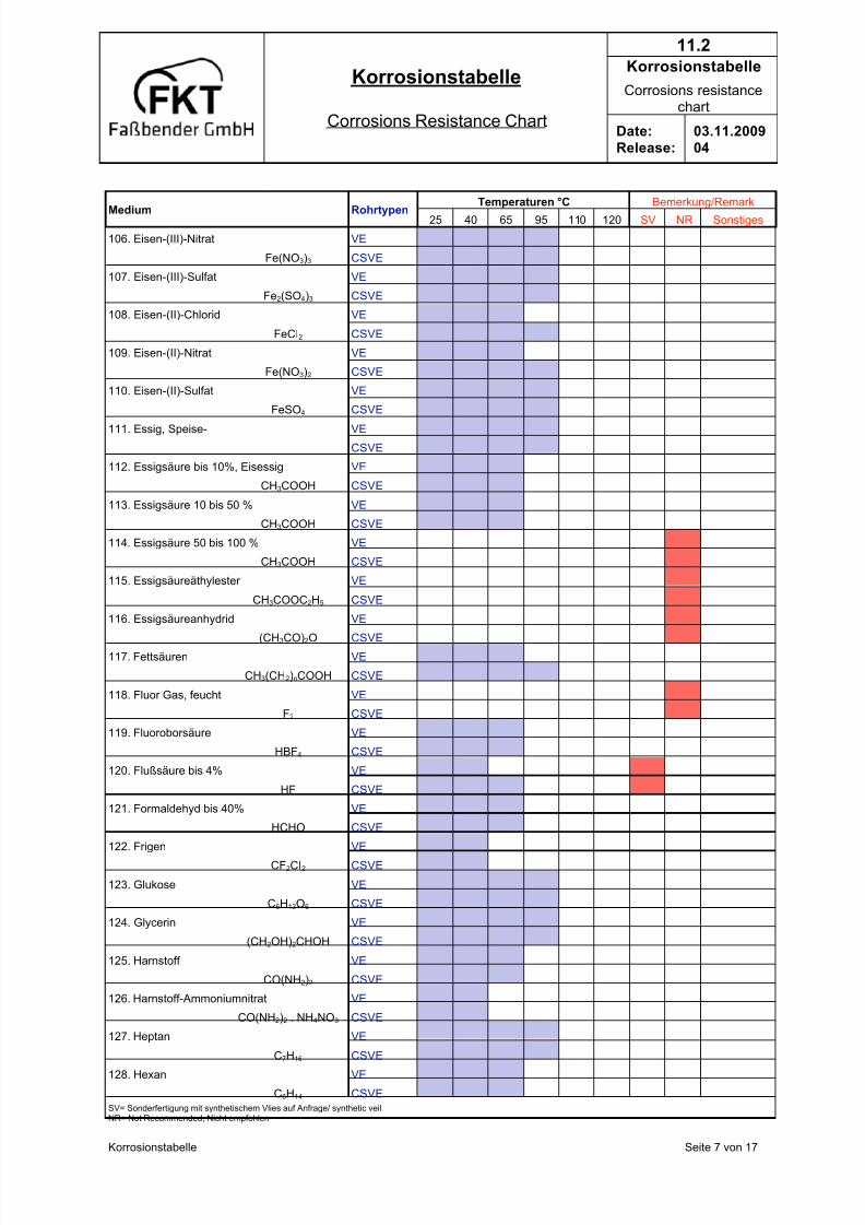


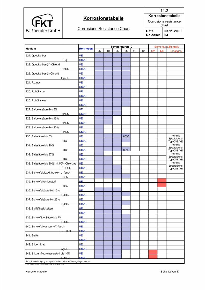


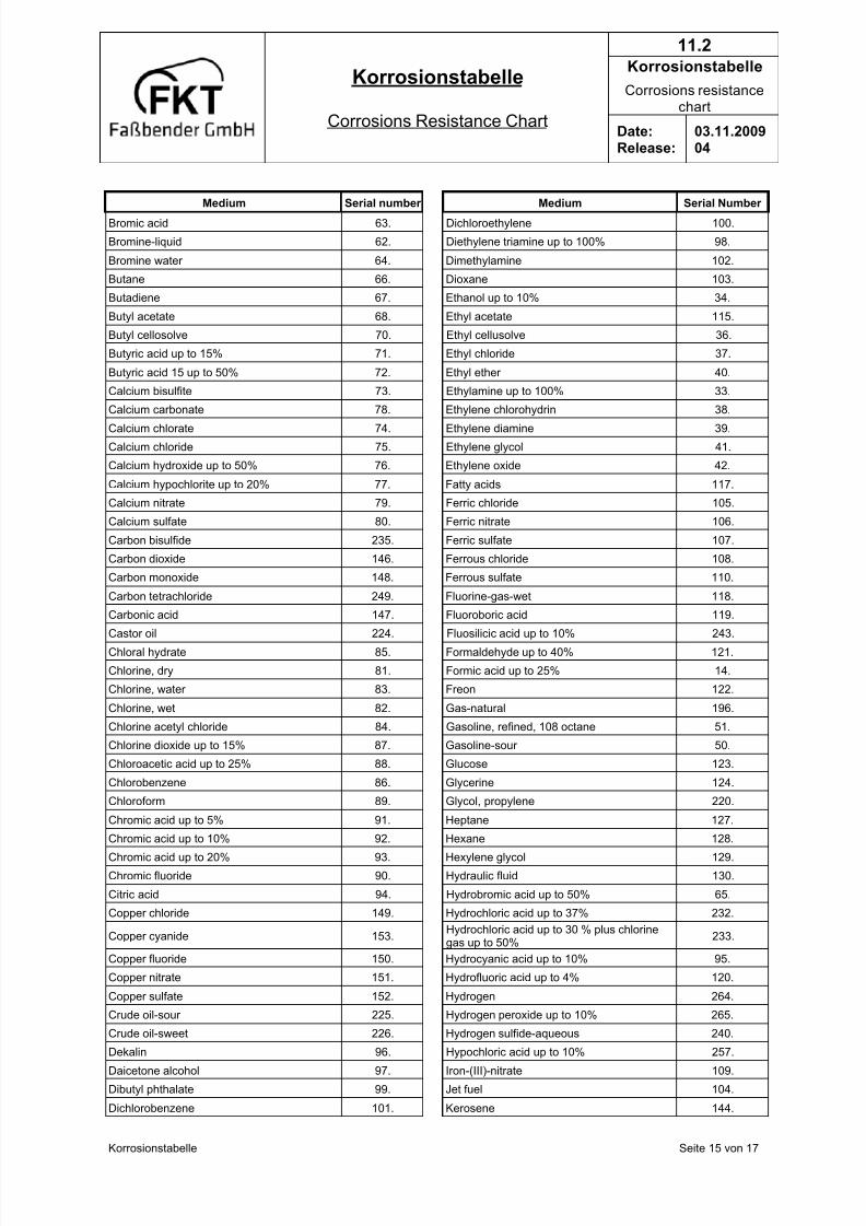

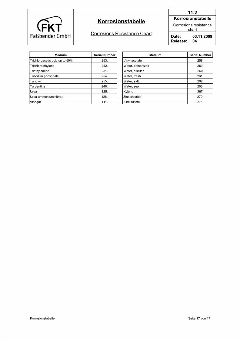


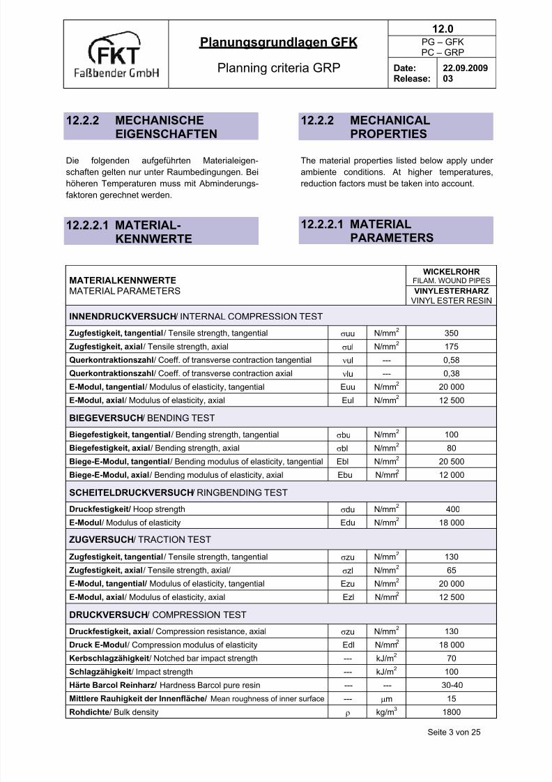
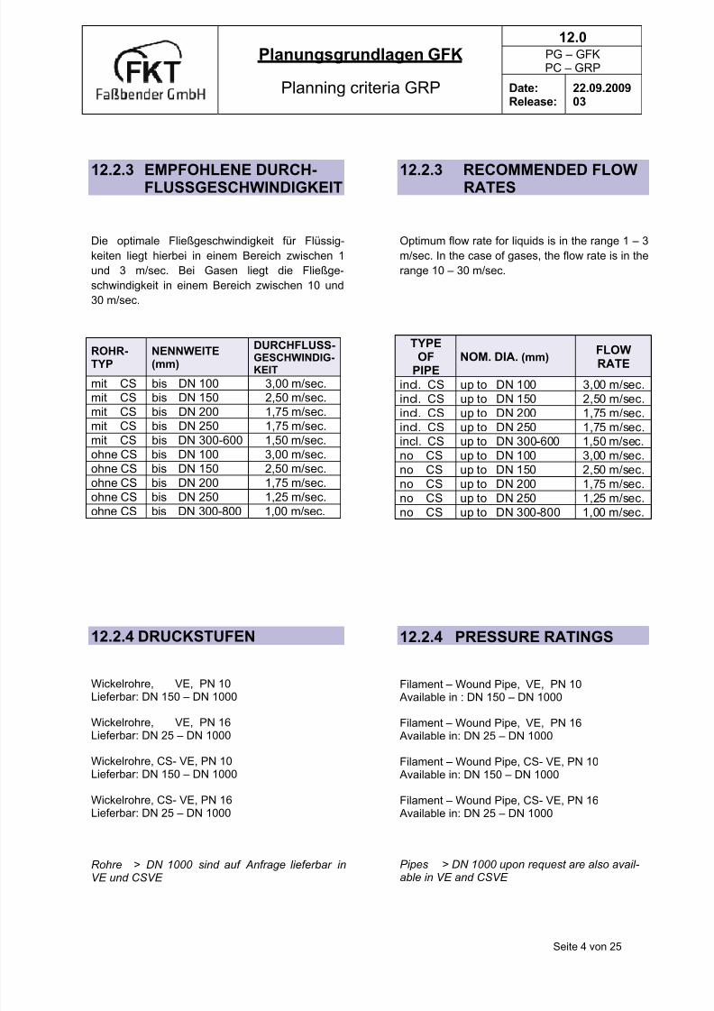

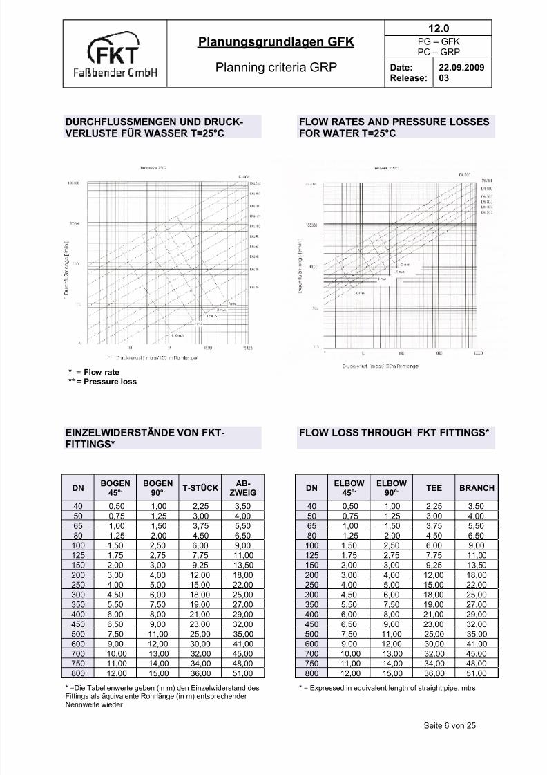


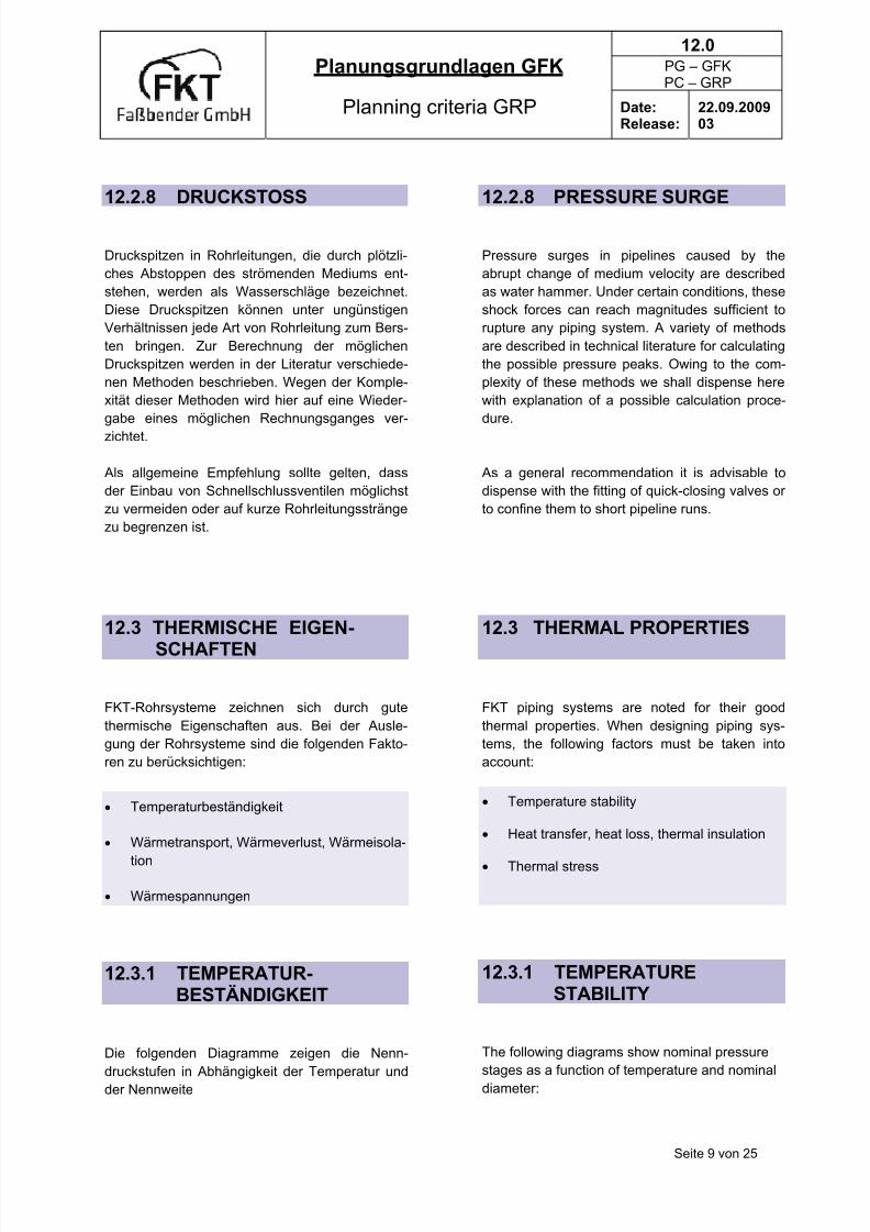
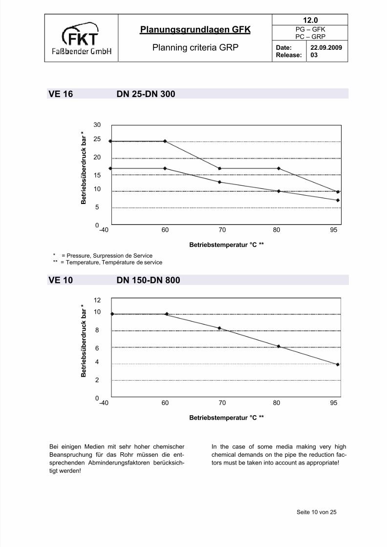

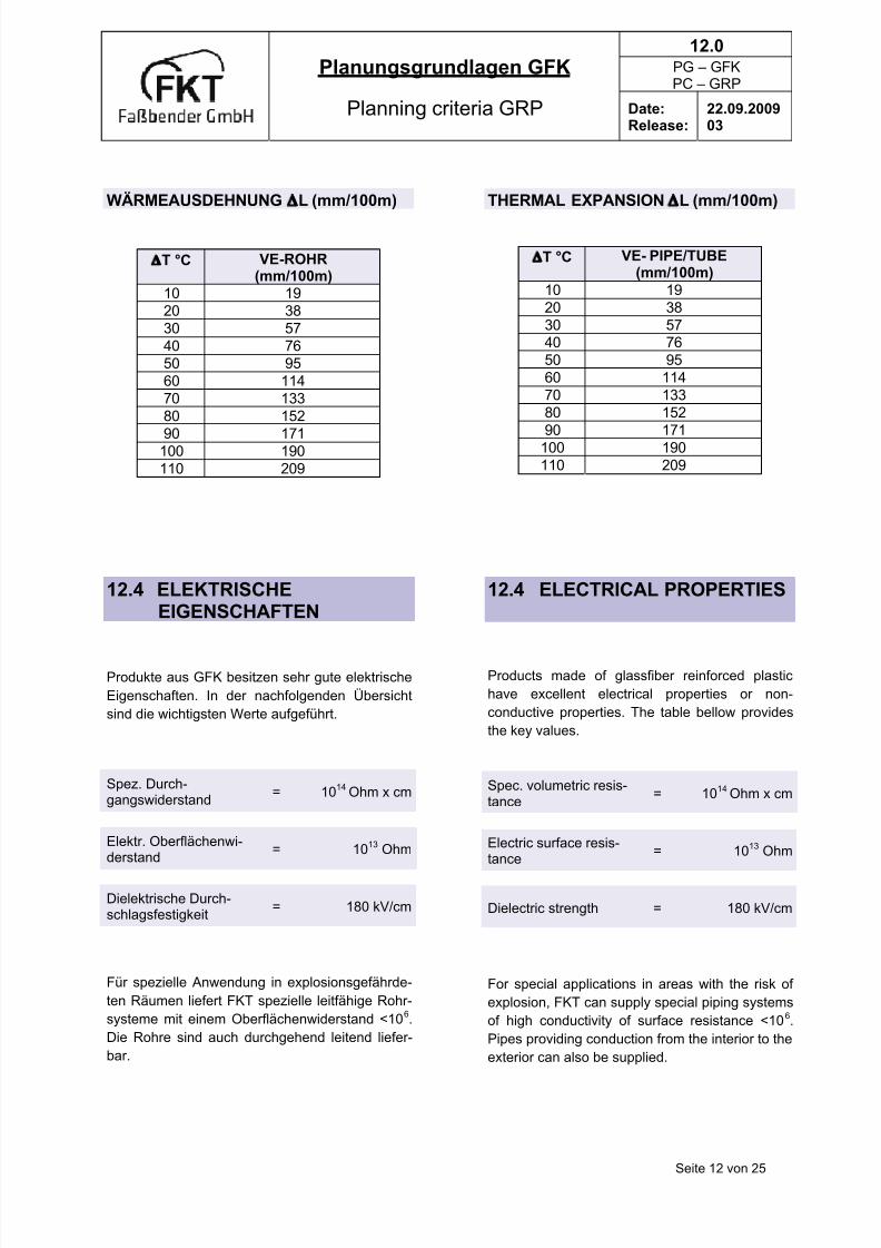
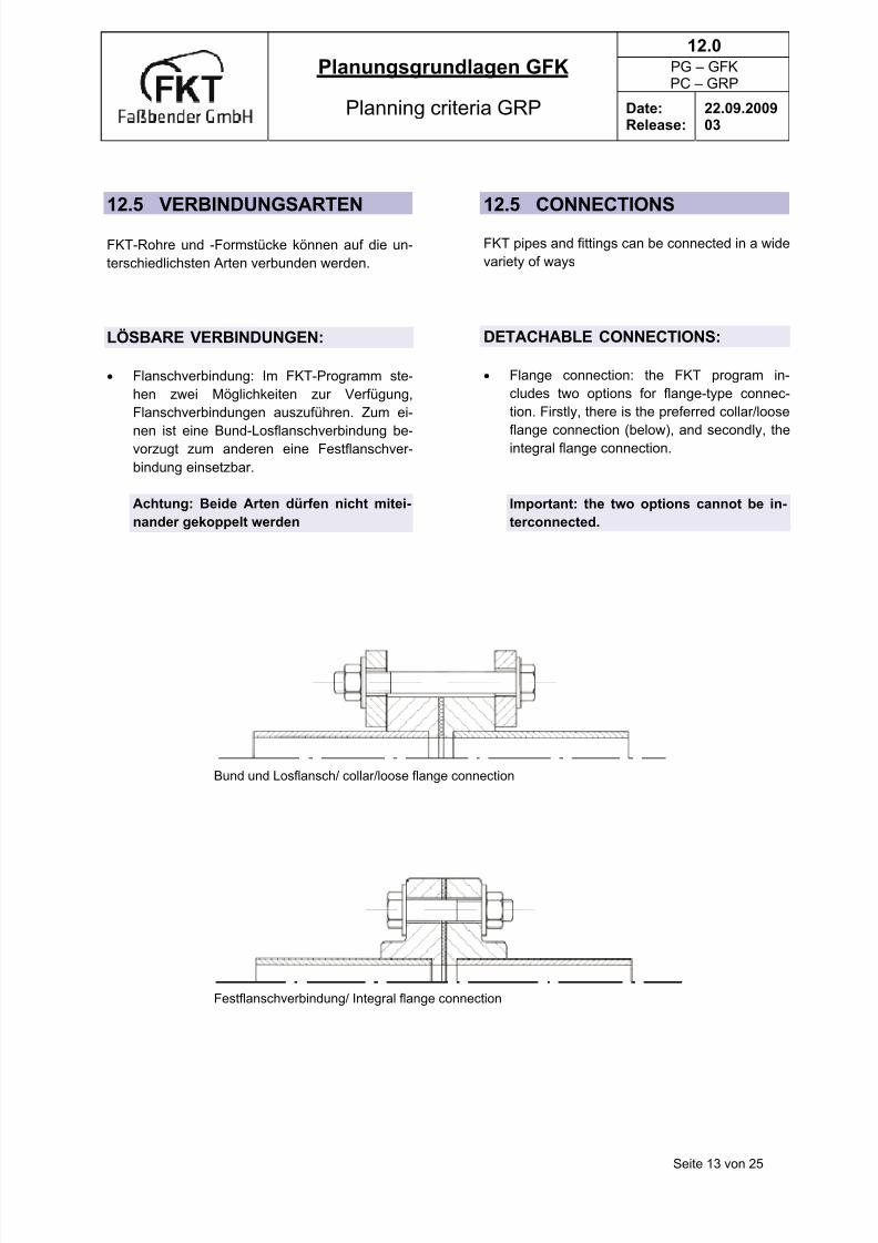
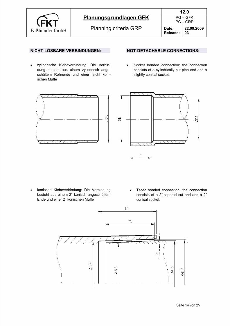


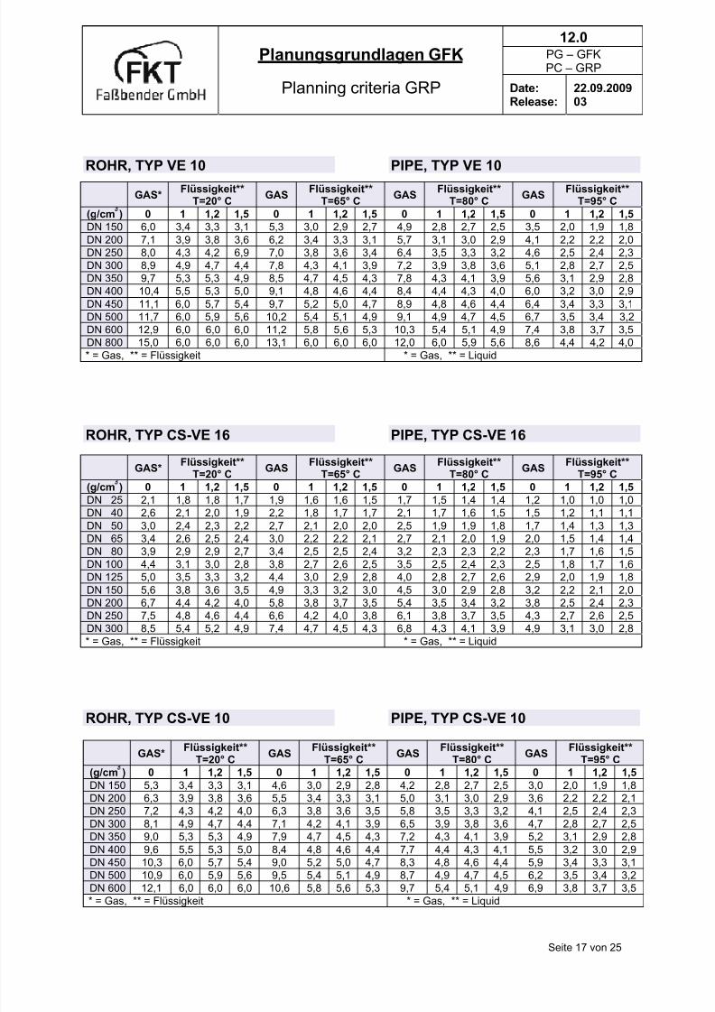
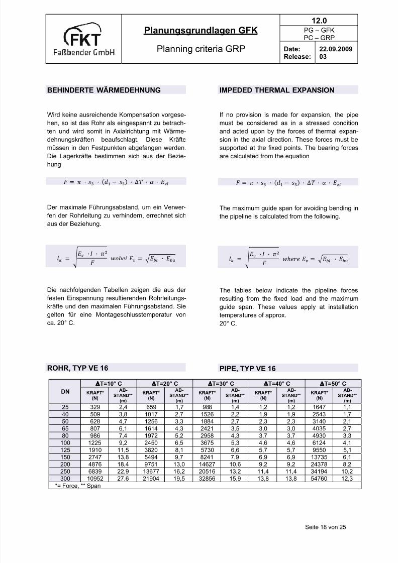


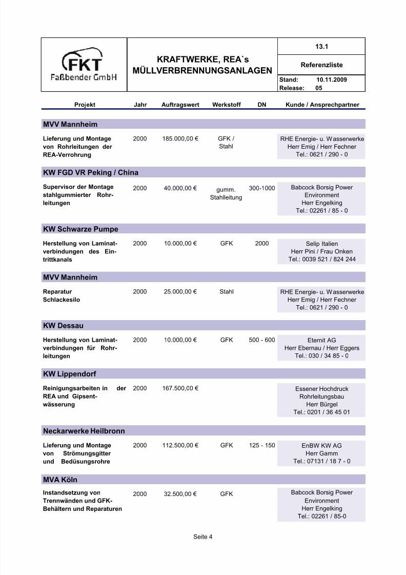


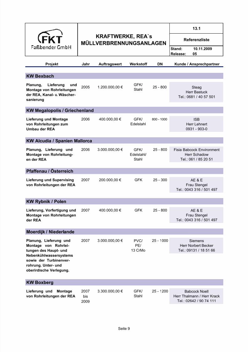
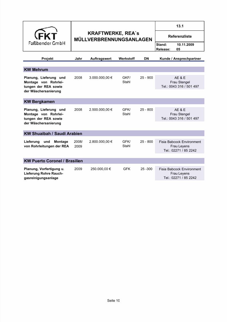

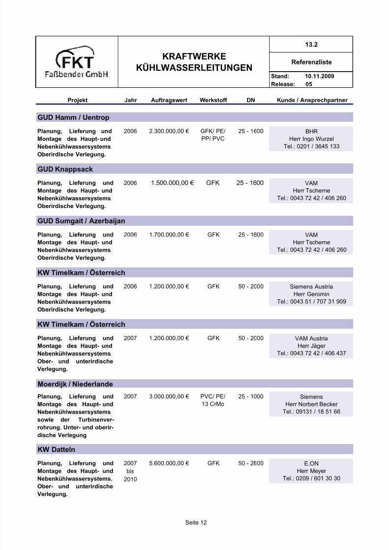


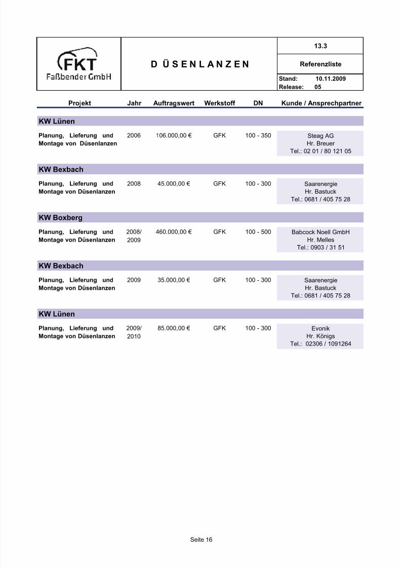

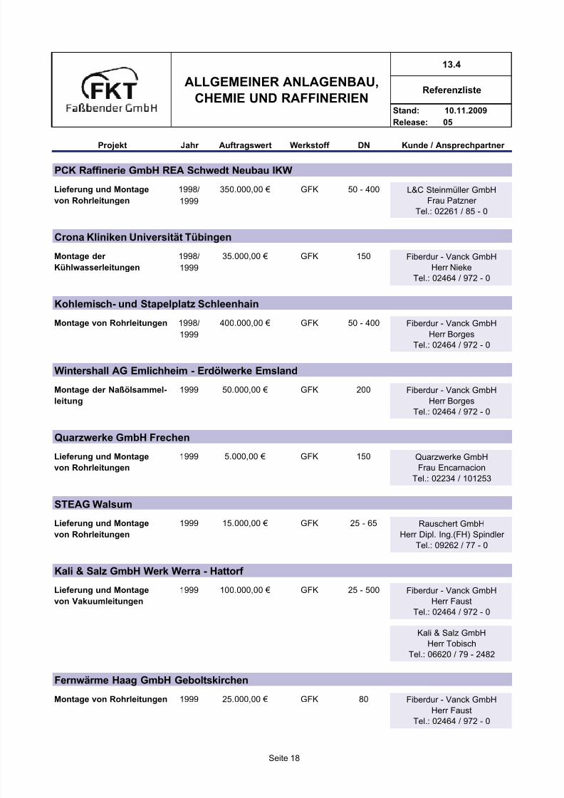

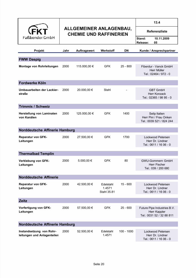


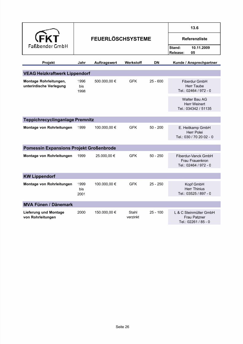
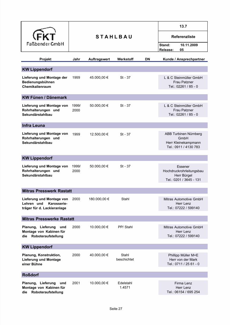

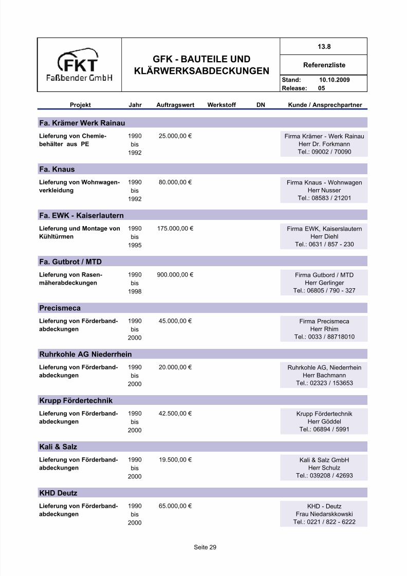
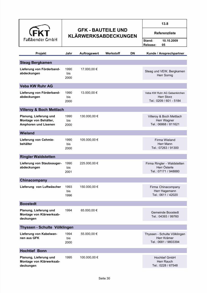


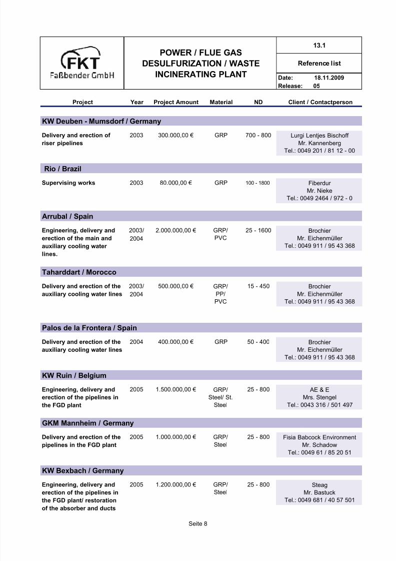
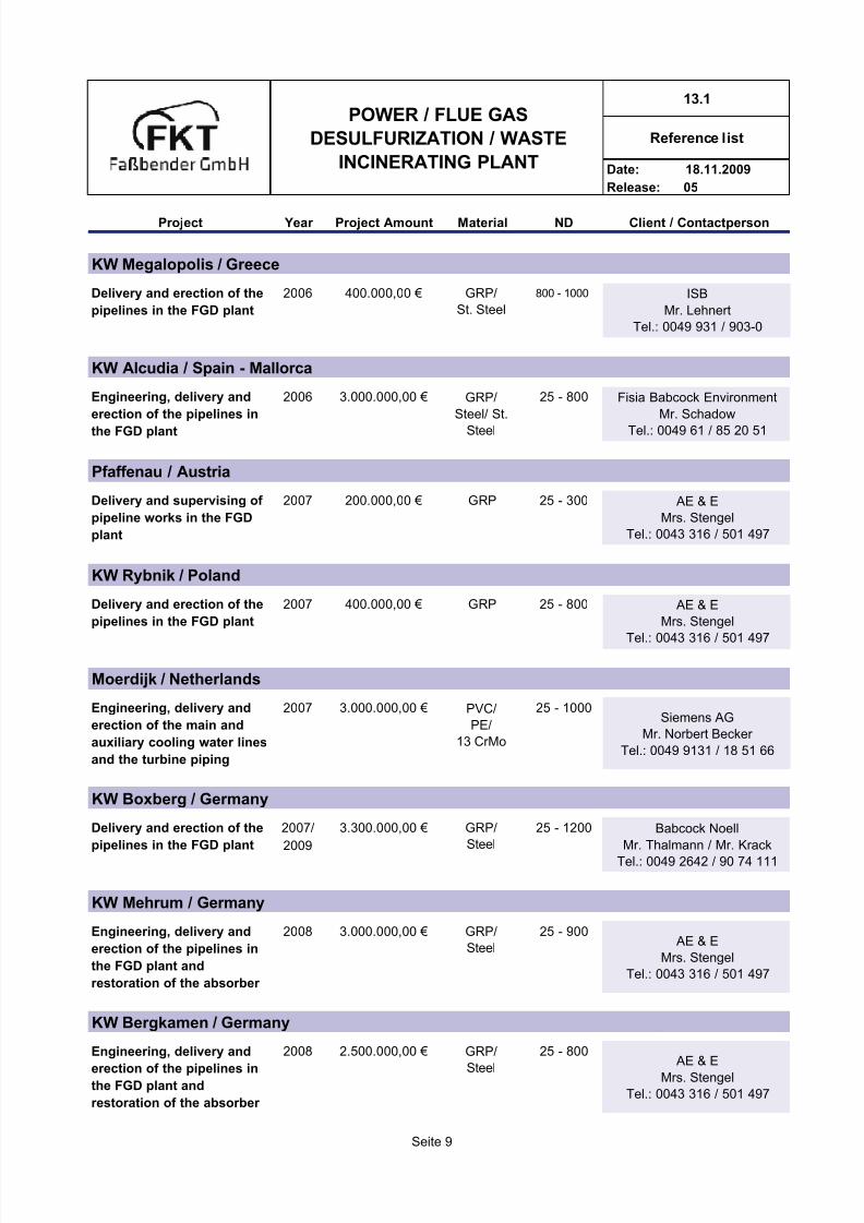
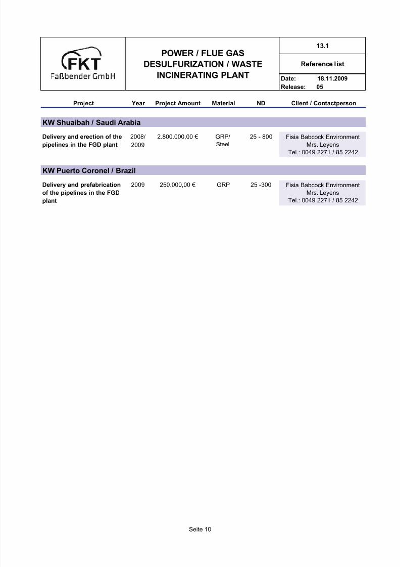
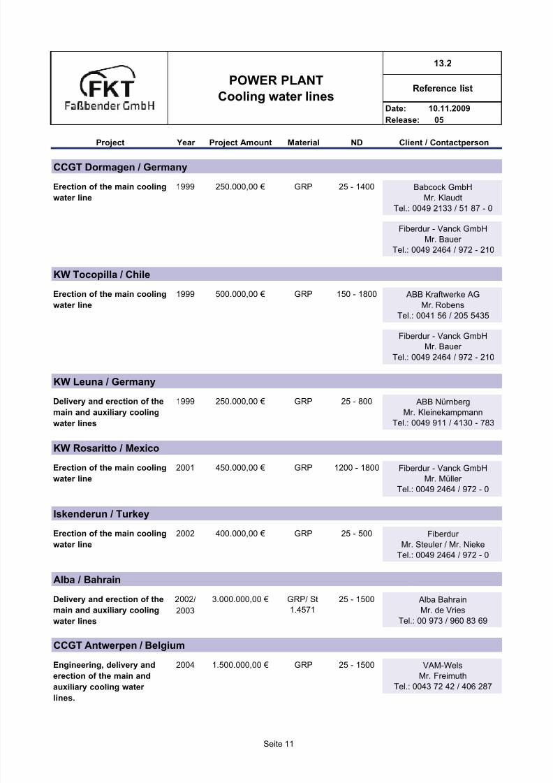

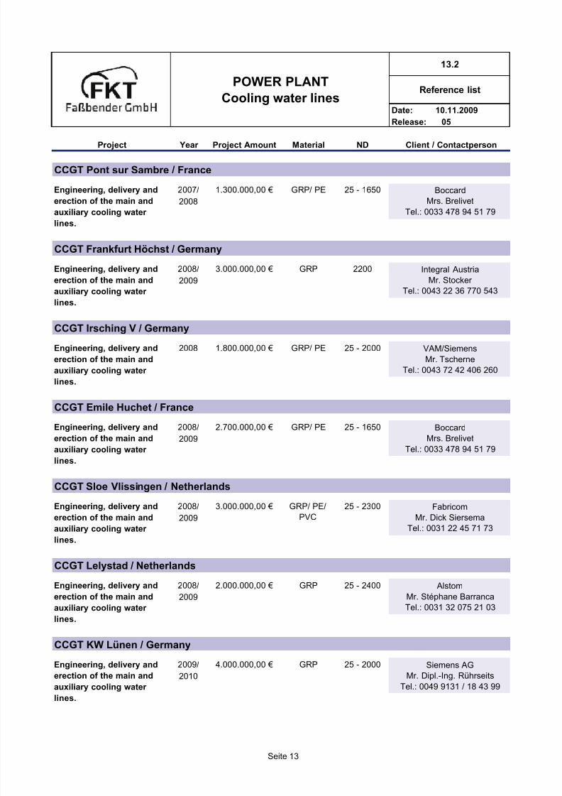


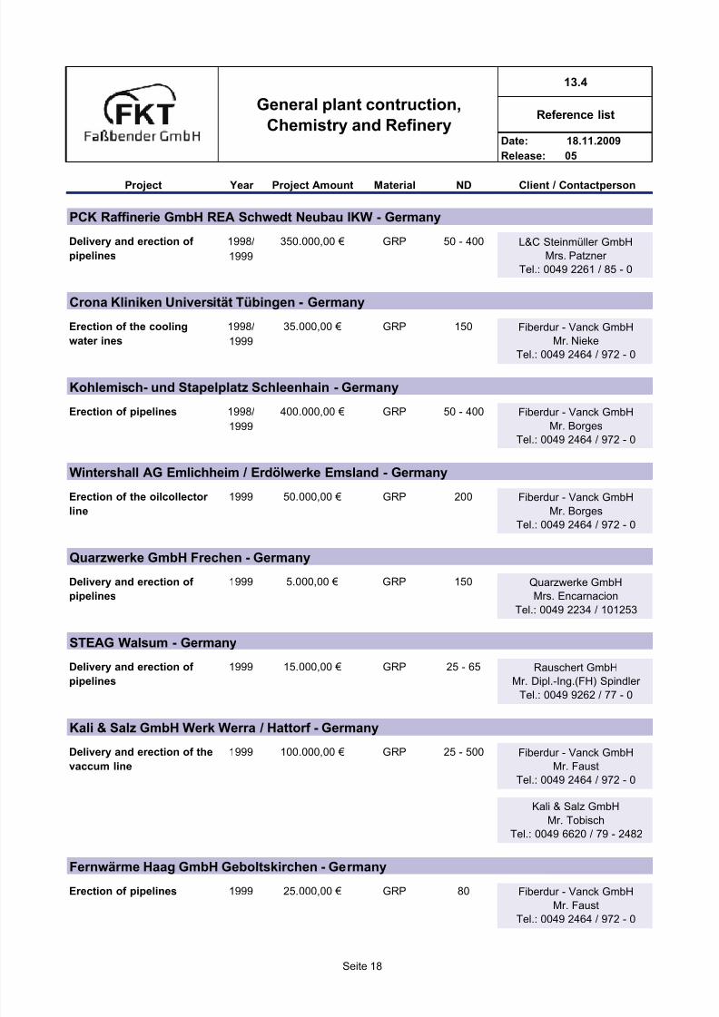


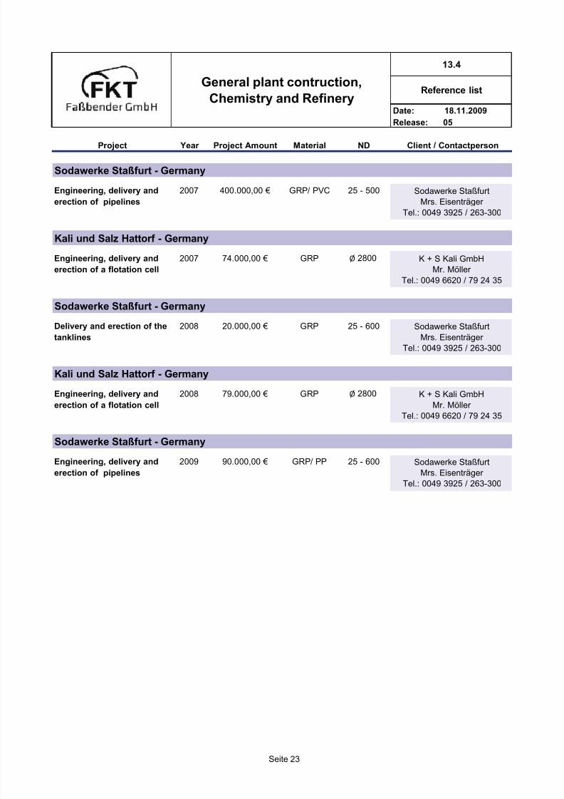
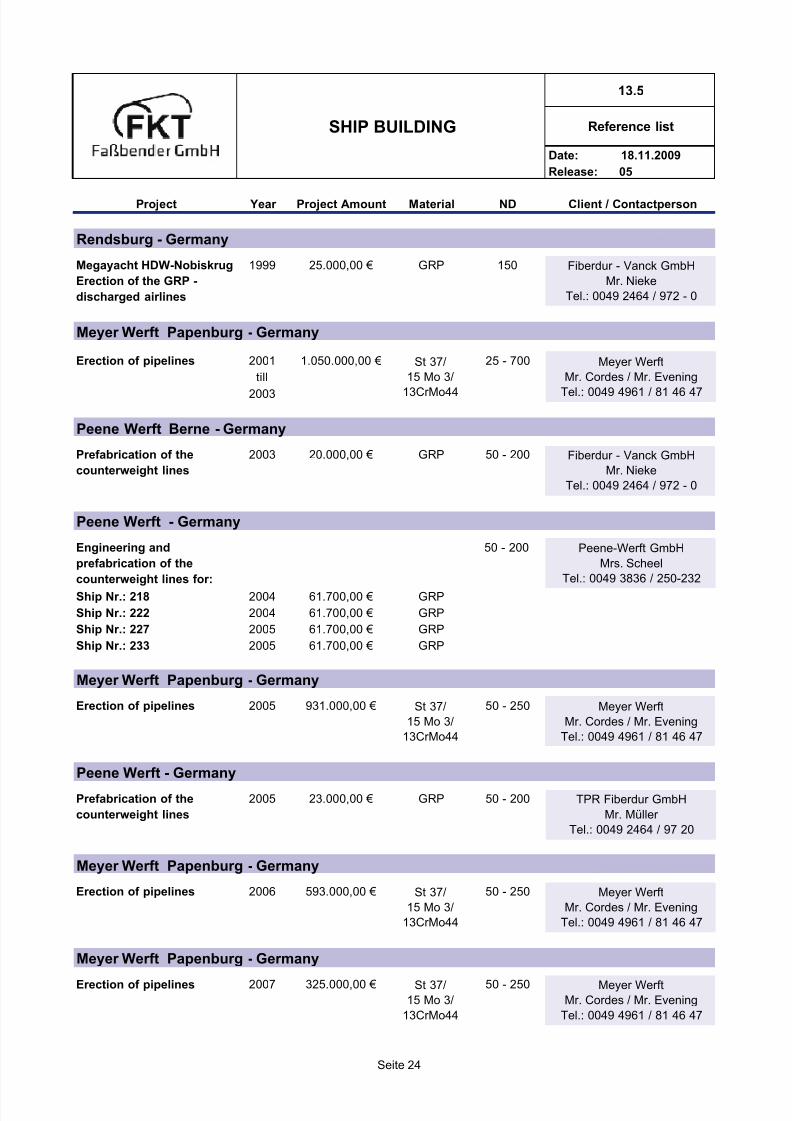
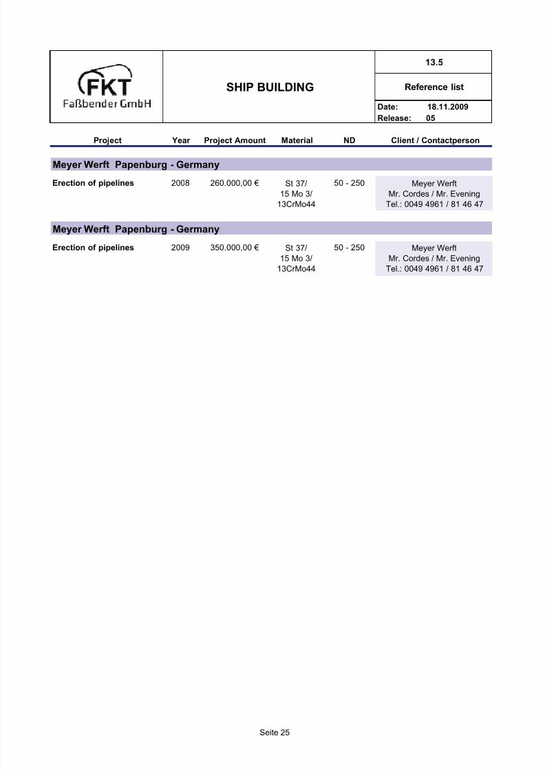


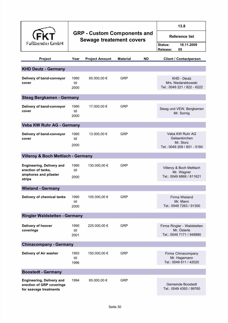

![g]kfn /fi6« a}+såf/f æsÆ ju{sf] O{hfht k|fKt ;+:yf Stronger … Annual...Gongab New Road u Swoyambhu Kapan Boudha Kamaladi Kuleshwo Kirtipur r Pata Jawalakhel Anamnagar Baneshwor](https://static.documents.pub/doc/80x56/5ab432ec7f8b9a86428b7c9c/gkfn-fi6-asff-s-jusf-ohfht-kfkt-yf-stronger-annualgongab-new.jpg)

![sDkgL P]g,@)^#, cGtu{t :yflkt€¦ · sDkgL P]g, @)^# cGtu{t :yflkt a}+s tyf ljQLo ;+:yf ;DaGWfL P]g, @)&# adf]lhd sfdsf/f]jf/ ug{] g]kfn /fi6« a}+saf6 Æsæ ju{sf] Ohfht kq k|fKt](https://static.documents.pub/doc/80x56/5f680427f904684ed509d047/sdkgl-pg-cgtut-yflkt-sdkgl-pg-cgtut-yflkt-as-tyf-ljqlo-yf.jpg)
![KERN FKT / IKT / PKT · 2016. 8. 24. · KERN & Sohn GmbH Ziegelei 1 D-72336 Balingen . E-Mail: info@kern-sohn.com Tel: +49-[0]7433- 9933-0 Fax: +49-[0]7433-9933-149 : Internet: .](https://static.documents.pub/doc/80x56/5fc17a06bf9e2c543b18e839/kern-fkt-ikt-pkt-2016-8-24-kern-sohn-gmbh-ziegelei-1-d-72336-balingen.jpg)


![90 - Nepal Electricity Authority · bf}/fgdf k|fKt ePsf tYo, ;FuflnPsf cg'ej Pjd\ pTkGg ePsf dfgl;s t/ª\ux¿nfO{ PsLs/0f ub}{ ;DalGwt :yfgsf] k|s[lt, hghLjg, dfgj dgf]lj1fg, k|fljlws–;f+:s[lts](https://static.documents.pub/doc/80x56/5f5ec062dc0c8760ac33029e/90-nepal-electricity-authority-bffgdf-kfkt-epsf-tyo-fuflnpsf-cgej-pjd-ptkgg.jpg)


![kl/R5]b @# s/sf] u0fgf · afl;Gbf k|fs[lts JolQm ckfË eP dfq o; bkmf cg';f/sf] 5'6 k|fKt x'g]5 . nufgL aLdfdf 5'6 ;'ljwf afl;Gbf k|fs[lts JolQmn] nufgL aLdf u/]sf] cj:yfdf k|fKt](https://static.documents.pub/doc/80x56/6061f1c005eb52563e1a6311/klr5b-ssf-u0fgf-aflgbf-kfslts-jolqm-ckf-ep-dfq-o-bkmf-cgfsf-56.jpg)