2.1.5 Employee Training and Maintenance ................................................................................... 152.1.6 Protection .............................................................................................................................. 17
2.2 Piping Systems ............................................................................................................................... 20
2.2.1 Location and Arrangement ................................................................................................... 20
or transmitted, in whole or in part, in any form or by any means, electronic, mechanical, photocopying, recording, or otherwise, without writtenpermission of Factory Mutual Engineering Corp.
Table 3. Space Separation for Flammable/Combustible Liquid Loading/Unloading Stations. ................... 35Table 4. The volume of a stoichiometric vapor-air mixture that may be produced from either
1 gallon or 1 liter of some common flammable liquids. (Note: these values are
based on complete vaporization of the liquid.) ............................................................................. 40
Table 5. Heat of Combustion for Representative Materials. ....................................................................... 43
This loss prevention data sheet provides recommendations for the prevention of and protection against fires
and explosions in occupancies handling, processing, or transferring flammable or combustible liquids. Datasheets covering specific occupancies may supersede this data sheet. Additional recommendations may be
needed to provide adequate prevention and protection features for a chemical process plant with the potential
for hazardous chemical reactions, three dimensional fires, or operating pressures in excess of 100 psig
(7 bar g). Refer to section 3.1 for guidelines on applying recommendations.
International standards may be applied, when required, instead of referenced United States standards
(i.e., ASTM, ASME, etc.).
NFPA 30, Flammable and Combustible Liquids Code , also covers this material.
1.1 Definition of Flammable and Combustible Liquids
1.1.1 Flammable Liquids
Flammable liquids are defined as liquids having closed-cup flash points below 100°F (38°C) and vapor
pressures not exceeding 40 psia (3 bar a) at 100°F (38°C) (thus excluding liquefied petroleum gases, liquefied
natural gases and liquefied hydrogen). Flammable liquids are referred to as Class I liquids, and are
subdivided as follows:
• Class IA liquids —flash points below 73°F (23°C) and boiling points below 100°F (38°C). Examples are
acetaldehyde, ethyl ether, ethyl chloride, isoprene, pentane and methyl formate. Class IA liquids are the
most hazardous from the fire protection standpoint due to their low boiling points and high volatility.
• Class IB liquids —flash points below 73°F (23°C) and boiling points at or above 100°F (38°C). Examples
1. This table assumes adequate sprinkler protection is provided in the Main Building and the exposure. Table also assumes damage limit-ing construction is designed in accordance with Data Sheet 1-44.
2. If sprinkler protection is not provided in the exposing building (i.e., low value building), use Data Sheet 1-20 (applies to Location 1 only).Use the following exposure rating in Tables 2–7 of Data Sheet 1-20:Exposure ‘‘A’’ for quantities greater than 1500 gal (6 cu m).Exposure ‘‘B’’ for quantities less than 1500 gal (6 cu m).Construction features for the exposing building still apply when an explosion hazard exists.
3. The types of construction are defined as follows:LW—light weight/noncombustible;NC—noncombustible;FR—1 hour fire rated;
PV—pressure venting;PR—pressure resistant.
4. Pressure resistant construction should also be provided for floors that have spaces below. Roof construction should meet the requirementslisted in Data Sheet 1-44.
5. For × <10 ft (3 m) with an explosion hazard, use Location 2, Explosion Hazard.6. For abutting structures with a fire hazard only, use Location 1, Fire Hazard, <50 ft/<25 ft (15 m/8 m).sprinklered and adequate dam-
age limiting construction, designed in accordance with Data Sheet 1-44, Damage-limiting Construction, is provided when an explosion
hazard exists.
Fig. 1. Preferred Locations for Processes Containing Flammable or Combustible Liquids. (Table 1)
Flammable Liquid Operations 7-32Factory Mutual Property Loss Prevention Data Sheets Page 5
2.1.1.6 Provide emergency drainage and/or containment for all flammable/combustible liquid areas protected
by water fire suppression systems. Determine the need for drainage and/or containment using Data Sheet
7-83, Drainage Systems For Flammable Liquids , Figure 1. The design of the drainage/containment system or
a possible alternative to adequate drainage should be in accordance with Data Sheet 7-83. Curbs and floorsin flammable/combustible liquid areas should be watertight. The surface grade around flammable/
combustible liquid areas should direct possible liquid releases away from important buildings.
Arrange drainage systems to prevent flammable vapors from backing up into buildings or rooms that are
tied into those systems. One method of accomplishing this is the use of trapped drains. Provide this arrange-
ment for all buildings/rooms with drains that are tied into a drainage system that can handle flammable/
combustible liquids regardless of the occupancy in that room/building.
2.1.1.5 When a flammable/combustible liquid occupancy creates a room explosion hazard (see section
3.1.4), provide damage limiting construction as recommended in Table 1 and Data Sheet 1-44, Damage
Limiting Construction . If a mist explosion hazard exists, refer to Data Sheet 1-44, Table 4, to design the
explosion venting. When damage limiting construction is not possible for small rooms that create a severe
exposure to high value adjoining occupancies, consider an explosion suppression system. Install the system
in accordance with Data Sheet 7-17, Explosion Protection Systems
2.1.2 Equipment Safeguards
Equipment that handles flammable and/or combustible liquids should be designed to: 1. Confine the liquids
and vapors within the equipment, 2. Keep escaping material to a minimum and prevent its spread, and 3.
Drain escaping liquids to a safe location.
2.1.2.1 Equipment and tanks should be closed or have a minimum of exposed flammable/combustible liquid
surface area and quantity.
2.1.2.2 Equipment should be constructed of materials that are compatible with the liquids in use and
surrounding environmental conditions, resistant to physical damage (e.g., impact), and are resistant to high
exposing temperatures (e.g., flammable liquid fire).Avoid glass and plastic equipment (e.g., tanks or vessels).
Metal equipment with a glass or plastic lining is acceptable. The equipment should be designed for the
maximum hydrostatic head plus the usual corrosion and wear factors. The equipment should also be
designed for use with flammable/combustible liquids.
2.1.2.3 Equipment containing flammable and combustible liquids should utilize indirect measurement or
observation instruments (e.g., thermocouple to measure temperature, sensor to measure pressure or liquid
level, etc.) to reduce or eliminate leakage in the event of instrument failure. When direct measurement or
and pressure, replace at regular intervals as determined by processing conditions.
h. Rotameters should be armored and arranged so only a sample of the flow is directed through the glass
reading chamber instead of the entire stream. Vents on air releases used in conjunction with somemetering devices should be piped to outdoor locations to prevent the release of flammable or combus-
tible liquids in the event of meter failure.
i. Conduct instrument maintenance, including tightening bolts and replacement, only when the associated
equipment or piping has been shut down and depressurized. Equipment containing flammable liquids
or gases should be emptied and purged.
2.1.2.4 Flammable or combustible liquid handling and processing equipment that, under normal operating
conditions, have the potential for a vapor-air explosion or mist explosion within the equipment (i.e., equip-
ment explosion hazard—see section 3.1.5) should be protected by one of the following methods (listed in
order of preference):
a. Provide explosion venting designed to limit the pressure developed by an explosion to approximately
133% of the equipment’s yield strength (stress). If damage to the equipment creates a significant expo-
sure (i.e., high value equipment or difficult to replace), design the explosion venting to limit the pressure
development to approximately two thirds (2 ⁄ 3) of the equipment’s yield strength (stress) (i.e., prevent
permanent equipment deformation). Equipment explosion venting calculations are presented in the
Appendix (Section 4.2.5). The initial pressure of the equipment must be considered when calculating the
needed vent size.
b. Design the equipment to contain the maximum expected pressure due to a vapor-air explosion. The
maximum pressure should not exceed 133% of the equipment’s yield strength (stress). To prevent
permanent equipment damage, the maximum pressure should not exceed two thirds (2 ⁄ 3) of the equip-
ment’s yield strength (stress). Most vapor-air explosions will produce a maximum pressure of approxi-
mately nine times the initial absolute pressure in the equipment (this applies to equipment operating at
atmospheric or at elevated initial pressures).
c. Provide a gas inerting system designed in accordance with Data Sheet 7-59, Inerting and Purging ,
that is arranged to prevent the creation of a flammable vapor-air mixture. The inerting system should have
a reliable inert gas supply. Equipment operators should be well trained on the importance and functionof the inerting system.
d. An explosion suppression system, designed in accordance with Data Sheet 7-17, Explosion Protection
Systems , should be provided on high value equipment, equipment that exposes high value processes,
or equipment with frequent explosions, when either explosion venting, containment, or inerting cannot be
provided.
2.1.2.5 Provide purging or ventilation systems for equipment with a vapor-air explosion hazard to reduce
the risk of creating a vapor-air mixture in the flammable (explosive) range (not needed on inerted equip-
ment). Design purging systems in accordance with Data Sheet 7-59, Inerting and Purging . Ventilation systems
should be designed in accordance with Data Sheet 6-9, Industrial Ovens and Dryers . Utilize purging to avoid
passing through the flammable (explosive) range of the flammable vapor during start-up or shutdown opera-
tions. Design ventilation systems to limit flammable vapor concentrations to less than 25% of the lower flam-
mable (explosive) limit (these systems are normally found in ovens and dryers).
2.1.2.6 Supports for important equipment or equipment containing flammable/combustible liquids
(e.g., mixing tanks, storage tanks) that are blocked from ceiling sprinkler discharge (i.e., equipment that is
wider than 3 ft (0.9 m) or 10 sqft (0.9 sq m) in area) should be protected against potential failure due to the
high temperatures created by pool fires. Use automatic water spray or sprinklers, arranged to protect the
supports, in rooms without a room explosion hazard. Use reinforced concrete or protected steel supports when
a room explosion hazard exists or as an alternative to water spray or sprinklers.
2.1.2.7 Tanks, mixers and other equipment to which flammable or combustible liquids are transferred should
be arranged to prevent accidental overflow. One or a combination of the following methods or equivalent
should be used (listed in order of preference):
a. Provide a trapped overflow drain leading back to the source of supply or to a point of safe discharge.
The capacity of the overflow drain should be at least equal to that of the fill pipe.
Flammable Liquid Operations 7-32Factory Mutual Property Loss Prevention Data Sheets Page 7
b. A liquid level-limit switch arranged to stop the liquid flow by closing a valve or stopping the pump should
be provided. An audible alarm may be used as a first warning that is followed by shutdown of the liquid
flow. The liquid level-limit switch should be FMRC-Approved. This arrangement is acceptable if the equip-
ment normally operates under pressure so that an overflow drain is not practical but overflow is possibleduring filling because of open manholes or sampling connections. This may also be used in conjunction
with an overflow drain (provide an alarm to prevent overflow).
The use of weigh tanks, measuring tanks, and dispensing meters to accurately provide a measured quantity
of liquid to a tank will assist in the prevention of overflows. Arrange weigh tanks and measuring tanks to
prevent overflow (using either ‘‘a’’ or ‘‘b’’). The use of a dispensing meter does not eliminate the need to follow
recommendations a and b above.
2.1.2.8 Provide overflow protection and emergency bottom drains for open top tanks to prevent overflow
due to sprinkler discharge and hose streams and to remove the exposed flammable/combustible liquid from
a fire area. The overflow protection and emergency bottom drains should be designed in accordance with
Data Sheet 7-9, Dip Tanks . Sprinkler discharge overflow protection may be omitted if the exposure created
by spilling flammable/combustible liquids is limited and one of the following is provided:
a. The tank or equipment is equipped with automatic closing covers or normally closed covers.
b. The liquid in the tank has a flash point above 200°F (93°C).
c. The tank has a capacity of less than 100 gal (380 l) and there is less than 20 sq ft (1.9 sq m) of exposed
surface.
Provide at least 6 in. (150 mm) of freeboard on tanks without overflow protection.
2.1.2.8.1 Emergency bottom drains may be omitted if the exposure created by burning flammable/
combustible liquids is limited and one of the following exists:
a. The liquid has a flash point greater than 200°F (93°C).
b. The tank has a capacity of less than 500 gal (1900 l) and is located on the first floor.
c. The tank has a capacity of less than 150 gal (600 l) and is located on an upper floor.
2.1.2.9 Equipment heating should be provided by steam, hot water, organic heat transfer fluid (see Data
Sheet 7-99) or other means not requiring an open flame. Arrange heating equipment for automatic control.
Provide a high temperature interlock arranged to provide an audible alarm and shut down the heating equip-
ment. Equipment and process temperatures should be continuously monitored by the operator. Maximum
equipment temperatures should be below the liquid’s autoignition or autodecomposition temperature.
2.1.2.10 Flammable/combustible liquid storage should be cut off from points of use (e.g., manufacturing
area). The quantity of flammable/combustible liquid in areas where they are used should be limited to one
shift’s needs (approximately 100 gal (400 l) or as specified by other specific data sheets).
2.1.2.11 Use drum pumps (preferred, easy control of liquid discharge) or self-closing faucets (gravity driven,
less control with failure of faucet), where permitted, for drums arranged for dispensing flammable and
combustible liquids. Use drip cans below faucets with on-side dispensing operations of Class I flammable
liquids (in areas where the ambient temperature can approach 100°F (38°C) include Class II combustible
liquids). A shallow metal drip pan is acceptable for use with Class II and III combustible liquids except as notedabove. The drum pumps, self-closing faucets, and drip cans should be FMRC-Approved.
2.1.2.12 Provide safety bungs on drums of Class I liquids arranged for upright dispensing with a drum pump
that is not equipped with pressure and vacuum relief vents. If ambient temperatures can approach 100°F
(38°C), safety bung use should include Class II liquids. Also provide safety bungs on drums of Class I, II and
III liquids arranged for on-side dispensing. Safety bung use for Class III liquids is intended to prevent possible
spillage during on-side dispensing. Safety bungs prevent the creation of vacuum during dispensing, prevent
the release of flammable/combustible liquids and their vapors, allow the release of excess internal pressure
that can be created when the drum is exposed to a fire (i.e., prevent a BLEVE), and prevent the flashback
of released vapor. Attach safety bungs only to the 2 in. (51 mm) drum opening to ensure its proper operation.
Provide safety bungs on intermittent drum storage of flammable or combustible liquids located in a dispensing
area if the stored drums will be exposed to a spill from the dispensing drum and sprinkler protection in the
7-32 Flammable Liquid OperationsPage 8 Factory Mutual Property Loss Prevention Data Sheets
area is not adequate for drum storage (Data Sheet 7-29, Flammable Liquids , Table 2) or sprinkler operation
may be delayed (e.g., locations under, 20 ft [6 m] high ceilings). Store the drums on the floor, upright and
a maximum of one high. If the dispensing area is adequately curbed and drained so a spill will not expose
the stored drums, safety bungs are not needed on the stored drums. Drums stored in adequately protecteddedicated storage areas do not need safety bungs.
2.1.2.13 Use FMRC-Approved safety cans for handling small quantities of Class I, II, and IIIA liquids.
Class IIIB liquids can be handled in nonrated containers.
2.1.2.14 Use FMRC-Approved flammable liquid storage cabinets for storing small quantities (type, quantity
and container size is limited by Approval Standard) of Class I, II, and IIIA liquids in manufacturing areas or
areas that are not designed for flammable or combustible liquid use. Provide mechanical ventilation in
cabinets where flammable vapors may be present (e.g., open containers, dispensing in cabinet). To maintain
cabinet integrity, the ventilation ducts should have a fire resistance similar to the cabinet. If ventilation is not
needed, keep the two ventilation openings closed to ensure the cabinet’s fire rating is maintained.
2.1.2.15 Flammable/combustible liquids should be transferred in closed systems. Arrange liquid pumping
and piping systems in accordance with recommendations listed in Sections 2.3 and 2.4.
2.1.3 Ventilation
Ventilation systems are designed to confine, dilute and remove the maximum normal amount of flammable
vapor released from equipment and handling of flammable and combustible liquids during normal opera-
tions. Adequately designed low level ventilation will reduce the chances of a flammable vapor-air mixture
accumulating in the process area. Excessive vapor release caused by equipment failure (pipe break, release
from a relief valve), accidental discharge of heated flammable/combustible liquids (drum or tank spill), or
an uncontrolled chemical reaction (venting a reactor) cannot be adequately safeguarded by the ventilation
rates provided below. Designing a ventilation system to remove a large vapor release is outside the scope of
this document.
2.1.3.1 Continuous low level mechanical ventilation designed to provide 1 cfm/sq ft (0.3 cu m/min/sq m) of
floor area should be provided in rooms or buildings where Class I liquids or liquids with a flash point up to
300°F (149°C) that are heated above their flash point are used.
2.1.3.2 In addition to providing the design in 2.1.3.1, the exhaust ventilation should confine flammable vapor
concentrations exceeding 25% of the lower explosive limit to within 2 ft (0.6 m) of points of release (e.g.,
open mixing or dip tanks, dispensing stations).
2.1.3.3 Exhaust air should be removed through a system of blowers, fans and ductwork terminating out of
doors away from air inlets, doorways and other openings. Exhaust ducts should be constructed of noncom-
bustible materials. Run the ducts as directly as possible to the outdoors with a minimum of bends. Protect
long runs of ventilation ducts with the potential for accumulation of combustible deposits in accordance with
Data Sheet 7-78, Industrial Exhaust Systems . Exhaust systems for small rooms may consist of a fan installed
at floor level arranged to exhaust out of doors (i.e., installed in wall).
The ventilation system should take suction within 12 in. (0.3 m) of the floor. Locate intake openings at open
tank lips, near equipment or dispensing, and in any pits located within the cutoff room or within 25 ft (8 m)
of the operations that produce vapors.
Ventilation systems that are arranged to recirculate air into the room should be provided with a FMRC-
Approved combustible gas detector arranged to stop recirculation and return to full exhaust when the vapor
concentration reached 25% of its lower explosive limit (LEL).
2.1.3.4 As a minimum, interlock exhaust fans with equipment power supplies. However, if flammable or
combustible liquids are kept in the room or building during idle periods, the exhaust ventilation should operate
continuously and be monitored (provide visual or audible ventilation failure alarm at occupied locations).
2.1.3.5 Provide make-up air inlets in exterior walls. Air inlets should be remote from exhaust outlets so that
air will sweep through the hazardous area. If gas or oil make-up air heaters are provided, they should be
indirect-fired and properly safeguarded.
Flammable Liquid Operations 7-32Factory Mutual Property Loss Prevention Data Sheets Page 9
If make-up air is taken from other plant areas, those areas should be free of flammable or combustible liquids.
Install automatic closing fire dampers or doors at make-up air inlet openings in interior fire walls or partitions.
The dampers or doors should have a fire rating equal to that of the walls.
2.1.3.6 For unheated liquids with a flash point greater than 100°F (38°C) and heated liquids with a flash
point greater than 300°F (149°C), provide natural draft ventilation arranged to provide 1 sq ft (0.1 sq m) of
free inlet and outlet opening per 500 sq ft (47 sq m) of floor area.
2.1.4 Ignition Sources
A basic design goal for occupancies that contain flammable and combustible liquids is the elimination and
careful control of all potential ignition sources. Prevention measures should prevent contact of an ignition
source with any flammable vapor-air mixture.
2.1.4.1 Provide hazardous location rated electrical equipment in accordance with Data Sheet 5-1, Electrical
Equipment in Hazardous Locations , and the NFPA National Electric Code, Article 500, when handling: a)
Class I liquids, or b) Class II or III liquids heated above their flash point (including possible ambient tempera-
tures). Electrical equipment should be FMRC-Approved. Class I Division 1 and Class I Division 2 areas
should be defined as follows:
a. Areas with less than 5 gal (19 l) of flammable/combustible liquid in a single container or piece of equip-
ment generally do not require rated electrical equipment (limited exposure).
b. Areas with 5 gal to 70 gal (19 l to 265 l) of flammable/combustible liquids in a single container or piece
of equipment should use either Figure 2a or 2b.
c. Areas with more than 70 gal (265 l) of flammable/combustible liquids, in a single container or piece
of equipment, with low pressures (less than 100 psig [7 bar g]) should use either Figure 3a or 3b. Electrical
equipment with contacts (e.g., make-and-break or sliding contacts: motors, switches, breakers, etc.)
should be avoided directly above and 10 ft (3 m) beyond the Class I Division 1 area. Provide light fixtures
with lenses to enclose bulbs. Protect all equipment against physical damage. If electric equipment with
contacts is located above a Class I Division 1 area, the contacts should be fully enclosed in a metal
housing.
d. Buildings or rooms where an explosion hazard has been determined to exist should use Figure 3a todefine Class I Division 1 areas. The remainder of the room or building should be defined as a Class I
Division 2 area (floor to ceiling).
Processes using flammable/combustible liquids at high pressures are not covered by this recommendation.
These occupancies require a full review of processing conditions to determine areas requiring hazardous
area rated electrical equipment.
The use of all nonrated equipment (including maintenance equipment, battery operated equipment, etc.)
unless it is recognized as being intrinsically safe, should be strictly prohibited in rated areas unless the area
has been purged of all flammable and combustible liquids as well as their vapors. An alternative is to provide
a pressurized or purged enclosure for the electric equipment designed in accordance with Data Sheet 5-1,
Electrical Equipment in Hazardous Locations.
Standard electrical equipment is acceptable in: a) areas handling unheated Class II or III liquids, or b)
above-grade areas with flammable liquid piping (no associated equipment such as pumps, valves, connectand disconnect points, filters, tanks, etc.).
2.1.4.2 Equipment handling Class I liquids or Class II and III liquids heated above their flash points should
be electrically bonded and grounded in accordance with Data Sheet 5-8, Static Electricity , Data Sheet 5-10,
Grounding , and NFPA National Electric Code, Articles 250 and 500. Proper grounding and bonding of equip-
ment reduces the potential for buildup of electric charge on separated pieces of equipment due to static
accumulations or stray electric currents.
2.1.4.3 Prohibit smoking or the use of open flames in all rooms or buildings requiring hazardous location
rated electrical equipment (i.e., Class I Division 1 or 2). Post signs to define hazardous areas and state restric-
tions for the area.
7-32 Flammable Liquid OperationsPage 10 Factory Mutual Property Loss Prevention Data Sheets
Thorough operator training and a complete maintenance program are fundamental components of any
process that utilizes flammable/combustible liquids. Both items will contribute to reducing the potential for afire or explosion as well as reduce the frequency and severity of such occurrences. As the complexity of
flammable/combustible liquid processes increase, the need for high levels of operator training and strong
equipment maintenance programs becomes essential to the proper operation of the process. Tailor training
programs and maintenance schedules to meet each location’s specific needs.
2.1.5.1 Create a training program for all employees (including operators, emergency organization members,
and security personnel) who have access to or work in areas containing or processing flammable/combustible
liquids. Design and supervise the training programs to address the complexity of process operations and
the hazard level present at a facility. The training should include proper handling, equipment operation, and
emergency procedures as well as the consequences of failing to follow the procedure. Provide training for
all new employees. Refresher programs should also be provided, as needed, for current employees. The
program should at least include:
a. The hazards created by the materials in use.
b. The proper operation or shutdown of the equipment under normal and emergency conditions. Critical
procedures should be printed and posted for convenient reference.
c. Proper material handling procedures (i.e., bonding/grounding, self-closing faucets, safety bungs, etc.).
d. Flammable/combustible liquid piping system operation and shutdown including the location of all local
and remote shutoff valves.
e. Proper flammable/combustible liquid transfer procedures.
f. The location, proper type and proper use of fire extinguishers for the hazard present.
g. Fixed extinguishing systems operation and function.
2.1.5.2 Establish an emergency response plan at locations handling or processing flammable/combustible
liquids. Design the plan to control the extent of damage due to fires or explosions by at least ensuring prompt
fire department notification, shutdown of fuel supply, and availability of provided fire protection features. Theplan should also include spill response procedures aimed at limiting spill size (e.g., prompt shutdown of liquid
flow), containing released liquid (e.g., use of sand bags), and elimination of all ignition sources that may be
exposed by the spill, or flammable vapors, until the spill is cleaned up. The actual extent of the emer-
gency response plan, including spill response procedures, will depend on the hazards present, facility size,
availability of emergency response personnel from surrounding communities (e.g., fire department, spill
response teams, etc.), and local, state or federal regulations.
The facility’s emergency organization members and the local fire department should be familiar with the
location of flammable/combustible liquid processes as well as the emergency response plan. Use emer-
gency response drills to reinforce the employee training programs (including emergency organization) and
assist the fire department in prefire planning.
2.1.5.3 Arrange security rounds to include areas handling flammable and combustible liquids during idle
periods. Train security personnel to ensure all equipment and valves that contain or control flammable and
combustible liquids are shut down (including pumps, emergency shutoff valves, mixers, etc.).
2.1.5.4 A series of routine checkpoints with normal condition limits should be inspected by the operator for
prompt detection of abnormal conditions. Determine the frequency of the checks by the process conditions
and severity of the consequences due to a process upset. Check all safety devices and process control
features at the beginning of each shift
2.1.5.5 All emergency shutoff valves for piping systems containing flammable and combustible liquids should
be clearly labeled with a sign indicating what is controlled.
2.1.5.6 Equipment (tanks, drums, etc.) containing flammable and combustible liquids should be clearly
labeled indicating the content of the equipment and the type of hazard they present (e.g., flammable,
combustible).
Flammable Liquid Operations 7-32Factory Mutual Property Loss Prevention Data Sheets Page 15
Piping containing flammable and combustible liquids should be labeled and color coded. Piping containing
specific flammable and combustible liquids should indicate the liquid name and direction of flow. Identifica-
tion is particularly important where piping passes through walls, at valves and fittings, and at points of use.
An acceptable piping identification system is described in ANSI A13.1. Pipe labeling and coding will reducemix-ups during liquid transfer, prevent mistakes during maintenance operations, and reduce confusion during
emergency responses.
2.1.5.7 Establish excellent housekeeping standards for areas storing or handling flammable and combus-
tible liquids. Clean up spills promptly. Keep waste materials in FMRC-Approved oily waste cans. Remove
waste daily. Maintain adequate aisles to permit unobstructed movement of personnel and access for fire
fighting.
2.1.5.8 Provide a raw materials inspection program to ensure delivery of expected materials and prevent
the introduction of foreign or incompatible materials into a storage or distribution system.
2.1.5.9 Management should strictly control all changes or new installations in processes or areas containing
flammable and combustible liquids. Conduct a full review of all planned changes by qualified loss prevention
consultants as well as other authorities having jurisdiction before the project begins.
2.1.5.10 Establish a complete preventive maintenance program designed to ensure that equipment is
operating as it has been engineered to operate. Refer to Data Sheet 9-0, Preventive Maintenance , to evaluate
existing programs or as a guide to develop new programs. This program should also include regular recorded
testing of safety devices and process control features in accordance with the manufacturer’s
recommendations.
Preventive maintenance programs for equipment and areas containing flammable or combustible liquids
should include: mechanical and electrical equipment, piping systems (e.g., connect/disconnect points, pumps,
flanged fittings, flexible pressure hoses, swing joints, etc.), system control devices (e.g., valves, computer
controllers, etc.), and emergency control or relief devices (e.g., emergency shutoff valves, float valves,
pressure relief devices, etc.). Follow preventive maintenance schedules closely to prevent the creation of an
ignition source (e.g., equipment breakdown and overheating, improperly sealed hazardous area rated electric
equipment) or the release of flammable or combustible liquid (e.g., pipe joint failure).
Conduct frequent inspections to detect and repair leakage. Use a flammable-vapor detector to locate smallleaks (detector should be FMRC-Approved). Prohibit the use of open flames or spark-producing devices.
2.1.5.11 Perform maintenance or repair operations only on equipment that has been depressurized, shut
down and drained of any flammable/combustible liquids. This includes tightening or loosening bolts or flanges,
packing glands, or making new connections. Piping should be depressurized, drained flushed, purged and
inerted before it is opened or tapped. Bolts for flanges or for connections to flanged fittings should be tightened
with a torque wrench to ensure proper tightness without overstressing. Prohibit the use of power tools unless
the precautions listed in recommendation 2.1.4.7 are strictly followed. Use FMRC-Approved safety tools in
areas where a flammable atmosphere may exist.
2.1.5.12 Relocate equipment needing repair or maintenance by use of a cutting torch or other hot work opera-
tion preferably to a nonhazardous location. Regardless of where the work is done, the equipment should
be drained, flushed, purged, and inerted as necessary to eliminate all flammable and combustible liquids and
their vapors. Use an FMRC-Approved combustible vapor analyzer (see Data Sheet 5-49) before and during
work to make certain equipment that is not inerted has been fully purged and remains purged of anyflammable vapors. Check equipment that is inerted before and during work with an FMRC-Approved oxygen
analyzer to ensure a flammable atmosphere is not present. Follow recommendation 2.1.4.7 and Data Sheet
7-59, Inerting and Purging , to ensure all flammable vapors and potential ignition sources have been
eliminated.
2.1.5.13 Use an equipment isolation procedure to supervise valves controlling flammable and combustible
liquids that are shut off for repair or other maintenance procedures. Equipment isolation procedures should be
strictly controlled to ensure equipment repairs/maintenance are complete before flammable/combustible
liquids are introduced.
7-32 Flammable Liquid OperationsPage 16 Factory Mutual Property Loss Prevention Data Sheets
2.1.5.14 Remove unused piping or tanks. Cap open end pipes promptly. Unused equipment that is not
removed should be completely drained and purged of all flammable/combustible liquids and their vapors.
The equipment should also be disconnected from any surrounding active equipment and clearly labeled as
shutdown to reduce the chances of accidental use.
2.1.5.15 Protect flammable and combustible liquid handling and transfer equipment against external
corrosion. Protective coatings for buried tanks and piping should be carefully applied and inspected before
they are covered. Conduct regular inspections of the equipment to investigate external corrosion. Increase the
inspection frequency of equipment located in corrosive atmospheres.
2.1.6 Protection
2.1.6.1 Provide automatic sprinkler protection over all areas storing, processing, or transferring flammable
and/or combustible liquids. Extend the sprinkler protection to the physical limits of the area. The physical limits
are defined by at least one hour rated fire walls and curbs. Sprinkler systems over areas defined by curbs
only (see Section 2.1.1.4) should extend over and 20 ft (6 m) beyond the curbed area. The sprinkler system
should be either a standard closed head, preaction or deluge type. Preaction systems are preferred over
dry systems for unheated locations. Install the sprinkler system in accordance with Data Sheet 2-8N,
Installation of Sprinkler Systems .
2.1.6.2 Provide sprinkler protection under any obstruction to water distribution that exceeds 3 ft (0.9 m) in
width or diameter and 10 sq ft (0.9 sq m) in area (e.g., under large tanks or pieces of equipment, below grated
mezzanines) to ensure adequate cooling for steel structures. Spacing below mezzanines should be 100 sq
ft (9 sq m) per head.
2.1.6.3 Automatic sprinkler protection may be omitted in building areas that contain no combustibles
(including combustible construction) other than flammable or combustible liquid piping if all of the following
exist:
a. The piping is welded with no flanged joints or has threaded joints that meet the criteria listed in
Section 2.2.3.6. Evaluate fire protection requirements for external pipe racks in accordance with Data
Sheet 7-14, Protection for Flammable Liquid/Flammable Gas Processing Equipment .
b. There are no valves, pumps, or other accessories that are known to be potential leakage points.c. The piping system consists solely of ferrous piping installed as recommended in Section 2.3 of this
document.
Automatic sprinkler protection may also be omitted in low value buildings (including pump houses, etc.) with
flammable and combustible liquid processes that have adequate space separation (see Sections 2.1.1, 2.3.1)
from important buildings and structures.
2.1.6.4 Sprinkler spacing should be a maximum of 100 sq ft (9 sq m) when protecting liquids with a flash
point less than 200°F (93°C) or greater than 200°F (93°C) and heated to its flash point. A maximum spac-
ing of 130 sq ft (12 sq m) when protecting liquids with a flash point greater than or equal to 200°F (93°C).
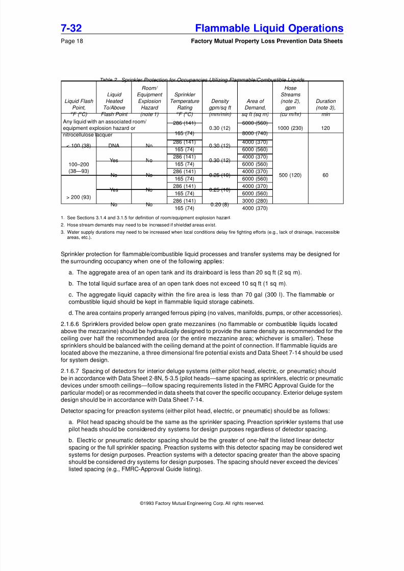
2.1.6.5 Automatic sprinkler systems (i.e., wet, preaction, or deluge) should be hydraulically designed as
indicated in Table 2. If a dry sprinkler system is provided, increase the sprinkler operating areas by 50%.
These tables apply to ordinary manufacturing occupancies that use flammable and/or combustible liquids (no
liquid quantity limitations) with no potential for a three dimensional fire. Refer to Data Sheet 7-14 for plantsor buildings that are dedicated to flammable/combustible liquid processing (i.e., plants with processes that
involve chemical reactions, chemical plants, etc.), any process that creates the potential for three dimen-
sional flammable/combustible liquid fires, or processes that operate at high pressures (pressures approxi-
mately 100 psig [7 bar g] or greater) . Sprinkler protection recommendations provided in other FM data sheets
that address specific occupancies that use flammable/combustible liquids supersede the recommenda-
tions in the document.
Flammable Liquid Operations 7-32Factory Mutual Property Loss Prevention Data Sheets Page 17
Table 2. Sprinkler Protection for Occupancies Utilizing Flammable/Combustible Liquids.
Liquid Flash Point,
o F ( o C)
Liquid
Heated To/Above
Flash Point
Room/
Equipment
Explosion Hazard
(note 1)
Sprinkler
Temperature Rating o F ( o C)
Density gpm/sq ft
(mm/min)
Area of Demand,
sq ft (sq m)
Hose
Streams
(note 2),gpm
(cu m/hr)
Duration (note 3),
min
Any liquid with an associated room/
equipment explosion hazard or
nitrocellulose lacquer
286 (141)0.30 (12)
6000 (560)1000 (230) 120
165 (74) 8000 (740)
< 100 (38) DNA No286 (141)
0.30 (12)4000 (370)
500 (120) 60
165 (74) 6000 (560)
100–200
(38—93)
Yes No286 (141)
0.30 (12)4000 (370)
165 (74) 6000 (560)
No No286 (141)
0.25 (10)4000 (370)
165 (74) 6000 (560)
> 200 (93)
Yes No286 (141)
0.25 (10)4000 (370)
165 (74) 6000 (560)
No No 286 (141) 0.20 (8) 3000 (280)165 (74) 4000 (370)
1. See Sections 3.1.4 and 3.1.5 for definition of room/equipment explosion hazard.
2. Hose stream demands may need to be increased if shielded areas exist.
3. Water supply durations may need to be increased when local conditions delay fire fighting efforts (e.g., lack of drainage, inaccessibleareas, etc.).
Sprinkler protection for flammable/combustible liquid processes and transfer systems may be designed for
the surrounding occupancy when one of the following applies:
a. The aggregate area of an open tank and its drainboard is less than 20 sq ft (2 sq m).
b. The total liquid surface area of an open tank does not exceed 10 sq ft (1 sq m).
c. The aggregate liquid capacity within the fire area is less than 70 gal (300 l). The flammable or
combustible liquid should be kept in flammable liquid storage cabinets.
d. The area contains properly arranged ferrous piping (no valves, manifolds, pumps, or other accessories).
2.1.6.6 Sprinklers provided below open grate mezzanines (no flammable or combustible liquids located
above the mezzanine) should be hydraulically designed to provide the same density as recommended for the
ceiling over half the recommended area (or the entire mezzanine area; whichever is smaller). These
sprinklers should be balanced with the ceiling demand at the point of connection. If flammable liquids are
located above the mezzanine, a three dimensional fire potential exists and Data Sheet 7-14 should be used
for system design.
2.1.6.7 Spacing of detectors for interior deluge systems (either pilot head, electric, or pneumatic) should
be in accordance with Data Sheet 2-8N, 5-3.5 (pilot heads—same spacing as sprinklers, electric or pneumatic
devices under smooth ceilings—follow spacing requirements listed in the FMRC Approval Guide for the
particular model) or as recommended in data sheets that cover the specific occupancy. Exterior deluge system
design should be in accordance with Data Sheet 7-14.
Detector spacing for preaction systems (either pilot head, electric, or pneumatic) should be as follows:
a. Pilot head spacing should be the same as the sprinkler spacing. Preaction sprinkler systems that use
pilot heads should be considered dry systems for design purposes regardless of detector spacing.
b. Electric or pneumatic detector spacing should be the greater of one-half the listed linear detector
spacing or the full sprinkler spacing. Preaction systems with this detector spacing may be considered wet
systems for design purposes. Preaction systems with a detector spacing greater than the above spacing
should be considered dry systems for design purposes. The spacing should never exceed the devices’
2.1.6.8 Sprinkler piping, valves, and fittings exposed by occupancies that create an explosion hazard should
be protected in accordance with Data Sheet 2-8N, Section 3-10, and Data Sheet 7-14.
2.1.6.9 Automatic sprinkler protection may be supplemented with a fixed special protection system (localor total flooding—gaseous, dry chemical, water spray) to limit the exposure created by a potential flammable/
combustible liquid fire. A special protection system should be provided to:
a. Limit fire damage and downtime for high value processes.
b. Limit exposure to high value surrounding occupancies that are susceptible to smoke and water damage.
c. Provide local protection for open tanks that are not accessible to fire fighting with portable extinguishers.
d. Limit the exposure created by inadequate space separation between important buildings or processes
and flammable/combustible liquid operations (e.g., loading and unloading stations, piping systems, etc.).
The special protection system should be FMRC-Approved and designed in accordance with the applicable
FM data sheet.
2.1.6.10 When an open (deluge) or closed-head AFFF (aqueous film forming foam) sprinkler system is
provided as an alternative to a standard sprinkler or deluge system, the following design criteria should beused (not acceptable in areas with a three dimensional fire potential or warehouse/storage areas):
a. Closed or open-head AFFF sprinkler systems should be hydraulically designed to provide either the
density listed in Table 2 or the minimum required density provided in the Approval Listing, whichever is
larger. The AFFF concentrate injection percentage should be in accordance with the Approval Listing. The
closed-head systems should be designed to deliver this density over the demand area listed in Table 2.
This protection is acceptable with or without adequate drainage (except when superseded by a specific
occupancy data sheet).
b. Exterior hose stream demand and water supply duration should be as recommended in Table 2.
c. Areas with adequate drainage in accordance with Data Sheet 7-83 should have at least a 10-minute
supply of AFFF concentrate provided. Areas without adequate drainage should have at least a 20-minute
supply of AFFF concentrate provided. The supply should be based on the sprinkler system design require-
ments, hose stream design requirements and the required concentrate injection percentage provided inparts (a) and (b) above.
d. Adequate containment designed in accordance with Data Sheet 7-83 should be provided when
adequate drainage is available. If adequate drainage is not available, containment should be designed
to hold sprinkler and hose stream discharge for the full 20-minute foam concentrate duration.
e. The AFFF concentrate should be compatible and FMRC-Approved for the flammable or combustible
liquid being protected. The AFFF delivery system (proportioning equipment, sprinklers) should be FMRC-
Approved.
f. The AFFF system should be installed in accordance with NFPA 16, Deluge Foam-Water Sprinkler and
Foam-Water Spray Systems , and NFPA 16A, Installation of Closed-Head Foam-Water Sprinkler Systems .
2.1.6.11 Portable extinguishers should be provided for areas (interior and exterior) utilizing or handling
flammable and combustible liquids. Extinguishers should be either carbon dioxide, dry chemical, or AFFF
type. Refer to Data Sheet 4-5, Portable Extinguishers , to determine effective sizes and locations for theextinguishers. Extinguishers should be FMRC-Approved. Protect extinguishers located outside against
freezing.
2.1.6.12 Provide small hose (11 ⁄ 2 in. [38 mm]) stations with combination spray/ solid stream nozzles in areas
utilizing or handling flammable and combustible liquids. Space hose stations to allow full coverage of the
area being protected. Add a water demand of 50 gpm (11 cu m/h) to the sprinkler demand for a single hose
station (100 gpm [23 cu m/h] should be added for more than one hose station).
2.1.6.13 Manual protection consisting of yard hydrants should be located within 200 ft (60 m) of all outside
flammable and combustible liquid handling and process areas (e.g., pump houses, loading and unloading
stations, valve-manifold houses, process structures, etc.). Provide manual foam protection for critical process
or handling areas containing liquids with flash points below 200°F (93°C). Manual foam protection can be
Flammable Liquid Operations 7-32Factory Mutual Property Loss Prevention Data Sheets Page 19
provided by a fixed water spray system, fixed monitor nozzles, or mobile monitor and hose nozzles. Design
the system in accordance with Data Sheet 4-7N, Foam Extinguishing Systems .
2.2 Piping Systems
2.2.1 Location and Arrangement
2.2.1.1 Locate flammable and combustible liquid piping systems outside (above or below ground) of important
buildings and structures. Arrange points of entry to buildings or structures to minimize inside piping and to
ensure a direct route to the point of use. Avoid piping flammable and combustible liquids through or under
buildings or process structures that do not use the liquids (e.g., reduce pipe length by taking a short cut
through a building).
2.2.1.2 Pipe routes should prevent or limit fire exposure to piping systems created by other plant occupancies.
2.2.1.3 Protect piping against mechanical damage. Do the following to prevent or limit mechanical damage
to piping:
a. Provide adequate clearance for aboveground pipe that passes over roadways or railroad sidings. The
amount of clearance provided should be posted on signs at each crossing point.
b. Locate buried piping at least 1 ft (0.3 m) from building foundations, railroad tracks or other facilities
subject to vibration and settling. Enclose piping that passes below building footings or railroad tracks in
a larger pipe.
c. Mark buried piping routes to permit visual determination of their location.
d. Interior pipe risers within 6 ft (1.8 m) of the floor that are exposed to vehicles or mobile equipment
should be installed inside of reinforced concrete columns, between flanges of steel columns, in a securely
anchored larger pipe, or provided with some other type of guard that will prevent contact with the mobile
equipment. Locate pipe risers in areas not exposed to mobile equipment or vehicles as close as possible
to walls or columns.
2.2.1.4 Protect interior and exterior piping (above or below ground) against external corrosion. Cover buried
pipe with noncorrosive backfill, or for ease of replacement and maintenance, place in covered masonrytrenches or split-tile ducts. Evaluate environmental conditions for aboveground installations to ensure
adequate precautions have been taken to prevent corrosion (e.g., exposure to weather conditions or corrosive
atmospheres).
2.2.1.5 Support exterior aboveground piping on noncombustible structures that are adequately protected
against vehicle impact damage. Piping may also be located on noncombustible building walls and above
noncombustible roofs. Place piping supported by a wall below window level. Piping runs above roofs should
have welded joints and avoid having known leakage points (e.g., flanged fittings, valves, meters, etc.).
Roofs supporting piping that contains known leakage points should be arranged to promptly direct any liquid
release to a properly arranged collection point through a dedicated collection and removal system (e.g., metal
collection pan below leakage points attached to a metal trough which directs a spill to a collection tank;
enclose entire piping system in a sealed metal duct arranged to direct spills to a containment tank). The liquid
collection and removal system should prevent damage to the roof covering due to liquid contact and prevent
the released liquid, or its vapors, from entering the building.
2.2.1.6 Avoid passing exterior pipe routes through service tunnels, sewer manholes, or other underground
pits.
2.2.1.7 Locate interior pipe routes either overhead or in covered (removable steel plates) trenches in the
floor. Avoid basement areas, vacant spaces below grade, and concealed or other inaccessible locations within
plant buildings. Place overhead piping as close as possible to ceilings and beams or along walls at least
6 ft (2 m) above floor level. If a floor trench is used, do the following to prevent the collection of flammable
vapor or flammable/combustible liquid in the trench:
7-32 Flammable Liquid OperationsPage 20 Factory Mutual Property Loss Prevention Data Sheets
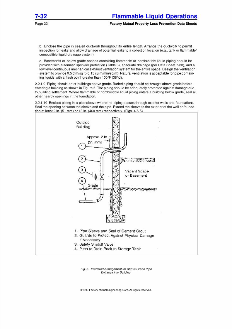
2.2.1.11 Arrange piping systems to permit drainage of its content during maintenance operations (repairs, cut-
ting and welding, etc.). This can be accomplished by pitching pipe back towards the supply, providing low
point drains, and providing flanged connections at various locations to permit disconnection and blanking of
the pipe.
2.2.2 Pipe Materials
2.2.2.1 Choose flammable and combustible liquid pipe materials using The American Society of Mechanical
Engineers (ASME) Standard B31.3-1990 or latest edition, Chemical Plant and Petroleum Refinery Piping ,
as a basic guideline. Consider the following factors when choosing a pipe material:
a. Chemical compatibility with the liquid to be handled.
b. Operating environment.
c. Operating strength (i.e., design for maximum expected pressure and temperature).
d. Resistance to mechanical shock (e.g., impact damage).
e. Resistance to thermal shock (e.g., quick cooling or heating due to expected and unexpected processconditions).
f. Resistance to high exposure temperatures (e.g., high melting point or noncombustible material that
will resist softening or decomposition when heated by an exposure fire).
2.2.2.2 Avoid materials such as cast irons, high silicon irons, plastics (thermoplastic, thermoset), glass, and
aluminum in flammable and combustible liquid piping systems due to their potential for failure (low impact
strength, low pressure ratings, low resistance to thermal shock, and low melting point). Seamless copper or
brass pipe and tubing is acceptable for use with flammable and combustible liquids in sprinklered locations
subject to the design conditions provided in ASME B31.3-1990 or latest edition.
2.2.2.3 Underground pipe should meet the above requirements (i.e., compatible with liquid in use, adequate
strength for maximum expected operating conditions, high impact strength, and high resistance to thermal
shock) but may be a low melting point material (e.g., plastic—thermoplastic, thermoset) since there is no
potential for a fire exposure.
2.2.2.4 Consider seamless steel pipe for interior piping systems that operate under severe cyclic conditions
(i.e., pressure cycles, thermal cycles—for example a hydraulic system) and create a significant exposure
to the facility.
2.2.2.5 Use stainless steel, nickel alloy, lined (glass, rubber, lead, plastic, etc.) steel pipe, or other similar
material when process conditions require high purity levels or create severely corrosive conditions. These
materials provide a high resistance to heat and mechanical damage. Lined pipe may fail internally with impact
or thermal shock, but the steel pipe shell will still contain the pipe contents.
2.2.2.6 Provide flexible all-metal seamless hose in piping systems exposed to vibration, settling or thermal
change. The installation should be in accordance with Section 2.2.4.
2.2.3 Pipe Joints
2.2.3.1 Piping systems containing flammable and combustible liquids should have welded joints. Provide alimited number of flanged joints to permit pipe system dismantling for equipment maintenance or removal.
Welded joints connecting pipe lengths and fittings should be butt welded in accordance with ANSI/ASME
B16.25, Butt Welding Ends , and ASME B31.3, Chemical Plant and Petroleum Refinery Piping , Chapter 5.
Welding should be done by qualified welders under close supervision, with all hot work safeguards observed.
The flanged joints should be provided at connections to system accessories (e.g., pumps, valves, tanks,
etc.) and at various points in-line (e.g., entrance to a room or building).
2.2.3.2 Design flanged joints in accordance with ASME B16.5, Pipe Flanges and Flanged Fittings , and ASME
B31.3. Provide the following for flanged joints:
a. Flanges should be constructed of forged or cast steel. Do not use cast iron flanges. Bronze flanges
are acceptable in sizes of 2 in. (50 mm) or less in sprinklered areas.
Flammable Liquid Operations 7-32Factory Mutual Property Loss Prevention Data Sheets Page 23
e. Resistance to decomposition or melting with an external fire exposure (e.g., noncombustible, high
melting point—greater than 1200°F [650°C]).
2.2.3.4.1 Use one of the following types of gasket for flammable and combustible liquid service:
a. Spiral-wound stainless steel, Monel, copper, Inconel 600, or equivalent metallic gasket with graphite,
ceramic, or equivalent filler.
b. Metal ring-joint gasket consisting of dead-soft aluminum, Monel, copper, or equivalent.
c. Graphite gasket without organic fillers or resins.
2.2.3.4.2 Other gasket materials consisting of fiber-sheet, paper, vegetable fiber, plastic, cork, lead, rubber,
Teflon, or equivalent are tolerable in existing systems located in sprinklered areas if all of the following are
true:
a. The operating pressure is less than 100 psig (7 bar g).
b. The system is noncylic.
c. The potential exposure created by a gasket failure is limited.d. The joints are outside and either underground or aboveground with limited exposure.
2.2.3.5 Join nonferrous metallic piping with flanged, brazed or flared connections. Brazing alloys should
have a minimum melting point of 1000°F (535°C). Do not use fillet-brazed joints or soldered joints.
2.2.3.6 Avoid threaded joints. New systems containing liquids with flash points of 200°F (93°C) and above
or existing systems (any flash point) with threaded joints can be considered tolerable when all of the following
are true:
a. The exposure created by leakage is minimal.
b. The piping system has an operating pressure less than 100 psig (7 bar g).
c. The piping system has limited leakage (constant repairs for leakage would indicate a change in joint
type is needed).
d. Operating conditions are not cyclic.
e. Operating conditions do not create corrosion problems.
If the piping creates a significant exposure, severe cyclic conditions exist or corrosion problems exist, replace
the threaded connections with butt welded joints. Piping systems with high pressures (greater than 100 psig
[7 bar g]) or leakage problems should have the threaded joints seal welded. A combination of leakage
problems and high system pressures in a piping system should have threaded joints replaced with butt welded
joints.
2.2.4 Flexibility and Support of Piping Systems
2.2.4.1 Design flammable and combustible liquid piping systems to provide adequate expansion and flexibility
to handle thermal expansion and contraction due to internal operating conditions (e.g., system temperature
changes) and external conditions (e.g., environmental effects) or other movements (e.g., fluid hammer
effects, settlement, vibration). Provide system flexibility to prevent: a) failure of piping or supports from over-stress or fatigue b) leakage at joints and c) creation of damaging stresses in piping, valves or other connected
equipment.
2.2.4.2 Evaluate piping system flexibility in accordance with ASME B31.3, Section 319. Provide system
flexibility by the use of pipe bends, welding elbows, pipe hangers, flexible hose connectors and other flexible
designs. Do not use expansion slip joints.
2.2.4.3 Provide pipe hangers to support and secure piping systems in accordance with the rules listed in
Data Sheet 2-8N, Installation of Sprinkler Systems , Section 3-15, or ASME B31.3, Section 321. Consider the
following when designing and installing hangers:
Flammable Liquid Operations 7-32Factory Mutual Property Loss Prevention Data Sheets Page 25
d. Enclose the pipe and steam-tracing in insulation.
2.2.5.4 An electric heating cable system should be arranged as follows:
a. Heating cable should be fastened along the pipe or spirally wound around the pipe. Enclose the pipe
and cable in insulation.
b. Heating cable should be continuous (no splices). Electrical connections should be visible for inspection.
c. Provide individual thermostat controls for each cable section. Fuses or fused disconnect switches of
as low a rating as practical should also be provided.
d. Electrical equipment (thermostats, plug assemblies, and switches) exposed to various weather
conditions should be enclosed in weatherproof housings. All sparking equipment (i.e., equipment with
make-and-break contacts) should be well separated from the pipeline and locations requiring hazardous
area rated electrical equipment.
e. All electric heating cable equipment should be FMRC-Approved.
2.2.5.5 An impedance heating system should be arranged as follows:
a. Systems should be installed and tested as complete units by the manufacturer or other qualified
installer. The installation should conform to the requirements of the authority having jurisdiction and Article
427—Fixed Electric Heating Equipment For Pipelines and Vessels, of the National Electric Code (1990
or current edition).
b. Piping sections that are heated should be insulated from unheated sections with electrically noncon-
ductive fittings to confine the current paths and to eliminate any current leakage at hazardous locations.
c. Provide an automatic high-temperature-limit cutoff switch in each circuit of each system to prevent
overheating of liquid in event of failure of the operating temperature control thermostat.
d. Enclose all parts of the piping and fittings in electrical and thermal insulating material to prevent
accidental grounding of the system. Provide a ground fault interrupt (GFI) device for the power supply
of all impedance heating systems.
e. Locate all sparking equipment (e.g., switches, transformers, contacts) well away from the pipeline andareas requiring electrical equipment rated for hazardous locations.
f. Test the heating system periodically to ensure its continued proper operation. All maintenance on the
system should be conducted by trained employees or contractors.
2.2.5.6 Insulation provided on the piping system should be noncombustible. Provide nonabsorbent insula-
tion (e.g., closed cell cellular glass) near flanged fittings or other potential leakage points (e.g., valves, pumps).
Any type of insulation (e.g., calcium silicate, glass fiber batts, mineral wool, etc.) is acceptable over welded
pipe.
2.2.6 Piping System Control Valves and Safety/Emergency Shutoff Valves
2.2.6.1 Flammable and combustible liquid piping systems should be provided with adequate valving to ensure
proper system control, regulation, isolation, and ability to shut down all fluid flow in the event of a fire.
2.2.6.2 Select control valves and safety/emergency shutoff valves using the following criteria:
a. The valve should be compatible with the liquid in use (including the packing and lubricants).
b. Valve bodies should be cast steel construction. Bronze is acceptable for valves 2 in. (50 mm) or smaller
installed in sprinklered areas. Use stainless steel, Monel, lined-steel, or an equivalent when process
conditions require the use of special materials. Cast iron bodies and yokes are not acceptable.
c. Rate the valve for the maximum expected system pressures and temperatures.
2.2.6.3 Consider the following for the selection and arrangement of process control valves:
a. Valves should provide positive indication of its status (i.e., open or closed, direction of flow).
Flammable Liquid Operations 7-32Factory Mutual Property Loss Prevention Data Sheets Page 27
b. Valves may be either manually operated at point of use or remotely operated depending on complexity
of the system. Remotely operated valves should fail in a safe position.
c. Arrange valves to ensure adequate control of liquid direction and flow rate. The valve arrangementshould also minimize the potential for improper system operation (e.g., allowing liquid flow to the wrong
tank, permitting too high a liquid flow rate, etc.). Proper valve operation can be accomplished through the
use of check lists for manual system operation and through process control systems for remote opera-
tion. Thorough employee training is needed for either approach.
d. Arrange control valves to isolate important equipment to permit maintenance operations or replacement.
e. Control valves that may be exposed to severe fire conditions (e.g., valves located in a flammable liquid
room) where loss of their function could significantly increase the exposure (e.g., valve controlling
flammable liquid flow from the bottom of a tank where valve failure would release the tank contents) should
be a FMRC-Approved firesafe shutoff valve.
2.2.6.4 Safety/emergency shutoff valves should be either diaphragm, solenoid, or fusible-element (weight
or spring operated) type. Positive displacement pumps may also be used as a safety/emergency shutoff. The
valves should be FMRC-Approved. Valves that may be exposed to a flammable/combustible liquid fire should
be FMRC-Approved fire safe shutoff valves.
2.2.6.5 Arrange safety/emergency shutoff valves to permit complete shutdown of liquid flow during a fire
and to limit the quantity of liquid released in the event of accidental escape. In general this can be accom-
plished by isolating the liquid supply and shutting off liquid at the various points of use. The actual number and
location of safety/emergency shutoff valves will vary depending on the piping system size, complexity and
potential exposure created by a release. All piping systems containing flammable/combustible liquids should
at least have safety/emergency shutoff valves in the following locations:
a. On discharge lines of interior or exterior tanks (aboveground or underground), arranged for transfer
by gravity, centrifugal pump, inert gas pressure, or other means that provide continuous pressure on the
system.
b. On bottom-discharge lines of exterior aboveground tanks feeding a positive displacement pump when
multiple tanks are located in the same area (e.g., two or more tanks in a diked area or a single tank in
a diked area that is not accessible during a fire) to permit supply shutdown in the event of a leak at thepump. A single exterior tank (e.g., single tank in a diked area that is accessible) feeding a positive
displacement pump may have a manually operated valve on the bottom-discharge line.
c. On bottom-discharge lines of interior tanks feeding positive displacement pumps to permit supply shut-
down in the event of a leak at the pump.
d. At points of use such as dispensing operations or delivery lines to equipment. Valves may be located
on each feed pipe to a piece of equipment/dispensing operation or on the supply pipe to a manifold feeding
equipment/dispensing operation. A single valve located at the entrance point to a building or cutoff room
is also acceptable.
2.2.6.6 Safety/emergency shutoff valves or positive displacement pumps should be arranged for automatic
and manual operation. In locations that are constantly attended and where leakage will be quickly discovered,
manual operation is acceptable. Arrange both automatic and manual valve operation to shut down all
flammable/combustible liquid flow in and to the area affected (i.e., shutdown valves at supply tank and atpoints of use).
2.2.6.7 Automatic operation of safety/emergency shutoff valves and/or positive displacement pumps should
be accomplished by one of the following methods:
a. Thermal actuation by use of heat detectors (e.g., HADs) located above the points of use (including
potential leak points, such as pumps, that create a significant exposure), fusible link operated valves, or
use of thermoplastic tubing for air supply to a pneumatic valve (loss of air supply will cause valve to close,
thermoplastic tubing will melt when exposed to a fire). Fusible link operated valve placement should ensure
it will be exposed to a fire caused by a flammable/combustible liquid release. If the valve’s placement
limits its exposure to a potential fire, the valve should either be arranged to ensure its operation (e.g., in
addition to link at valve, provide a second link over expected leak points with a cable attached to the valve
7-32 Flammable Liquid OperationsPage 28 Factory Mutual Property Loss Prevention Data Sheets
handle which is arranged to close when the cable releases) or be replaced with a valve that can be remotely
operated.
b. Actuation by operation of a fire protection system such as automatic sprinklers and special protectionsystems (water spray, gaseous extinguishing system, etc.). Safety/emergency shutoff valves may be tied
into pressure switches, waterflow alarms, or fire detection systems. Arrangements should be made to
permit protection system alarm testing without unwanted production shutdown.
c. Release of a dead-man type control or self-closing valve. These types of controls require constant
attendance by the operator and will close automatically when the operator leaves. Provide self-closing
valves at dispensing operations upstream of any flexible hose.
d. Actuation by abnormal system conditions such as high/low pressure and excess flow. Use this arrange-
ment to reduce a flammable/combustible liquid release before ignition when the expected fire or explosion
exposure is excessive. Provide this type of actuation system in addition to a method listed above (a–c).
2.2.6.8 Manual operation of safety/emergency shutoff valves and/or positive displacement pumps should
be accomplished by providing one or more stop buttons or switches located within the flammable/combustible
liquid operation area (arranged for easy access by the operators and at points of egress from the building
or structure) and at accessible remote locations (e.g., control room, security station, etc.).
2.2.6.9 Provide check valves in piping arranged to feed tanks, receivers, or other vessels when: a) the liquid
flow is in one direction only and b) the vessel can supply a leak in the feed pipe by reverse flow. Install the
check valve as close to the vessel as possible. Check valves used on systems with materials that may impair
their proper operation (e.g., paint, printing ink) should be physically checked regularly.
2.2.6.10 Provide hydraulic accumulators or safety relief valves on pipelines that can be valved off with liquid
trapped between valves to prevent damage or overpressure from thermal expansion of the liquid. Pipe the
relief valve discharge to a properly arranged collection point.
2.2.7 Inspection and Testing
2.2.7.1 Piping systems should be inspected and tested in accordance with ASME B31.3, Chapter VI.
Inspections should include all pipe joints (welded and flanged) and pipe supports. Conduct all testing before
painting, insulating, or burying of the pipe system.
2.2.7.2 Conduct pressure testing on all piping systems before introduction of flammable/combustible liquids.
Hydrostatic testing should be conducted, using water as a test liquid, for systems that will not be adversely
affected by water and with design pressures greater than 1 psig (0.07 bar g). Systems that are incompatible
with water or that have a design pressure less than 1 psig (0.07 bar g) should be pneumatically tested using
compressed air or inert gas (generally, pneumatic testing should be avoided when possible due to the high
release energy potential created by compressed gas).
2.2.7.3 The following should be provided to conduct a hydrostatic leak test on the piping system:
a. Vent the piping to permit removal of air within the system.
b. Relief valves, rupture disks, pumps, vessels of appreciable volume, and other portions of the system
rated below the test pressure should be blanked off or removed.
c. Reinforce piping supports if the test liquid is heavier than the liquid the system was designed to contain.
d. Pressurize the test liquid to 1.5 times the system’s design pressure. Consider normal operating
temperatures when picking a test pressure.
e. Hold the test pressure for at least 30 minutes.
f. While pressurized, the system should be visually inspected for leaks.
g. All leaks should be repaired and the system retested until the test pressure can be held for the stated
time period.
2.2.7.4 Provide the following to conduct a pneumatic leak test on the piping system. Conduct pneumatic
tests with caution due to the high release energy potential present in compressed gases.
Flammable Liquid Operations 7-32Factory Mutual Property Loss Prevention Data Sheets Page 29
a. Relief valves, rupture disks, pumps, tanks, and other portions of the piping system rated below the
test pressure should be blanked off or removed.
b. A pressure relief device set for the test pressure plus the lesser of 50 psig (3 bar g) or 10% of testpressure should be provided on the piping system.
c. Provide a test pressure of 110% of the design pressure or a minimum of 3 psig (0.2 bar g). The system
should be raised to the test pressure in steps to located large leaks at low pressures.
d. Hold the test pressure for 30 minutes.
e. After the test period, reduce the pressure to the design pressure and inspect for leaks using a solution
of soap and water.
f. All leaks should be repaired and the system retested until the test pressure can be held for the stated
time period.
2.3 Flammable and Combustible Liquid Transfer Systems
2.3.1 Transfer by Pumping
2.3.1.1 Arrange pumping systems to pressurize the piping system only when there is a demand for liquid
at the point of use. Avoid piping systems that are pressurized when not in use.
2.3.1.2 Arrange pumps to shut down when safety/emergency shutoff valves are actuated.
2.3.1.3 Arrange pumping systems to provide the minimum pressure required for system operation.
2.3.1.4 Use a positive displacement pump when possible to permit complete shutoff of liquid flow. A
centrifugal pump is acceptable but can only be arranged to shut off pumping. Liquid flow may continue by
siphoning or gravity flow.
2.3.1.5 Consider the following factors when choosing pump construction features:
a. Pumps should be cast steel construction. The pump, packing, and trim should be compatible with the
liquid being handled.
b. Studs used to attach packing glands to pumps should have the nuts on the outside ends to indicate
the amount of thread engaged. Avoid cap screws.
c. The pump casing, impeller, and other moving parts should be constructed of nonsparking materials if
the pump is to operate dry at frequent intervals.
d. Provide pumps with high integrity seals (dual seals) or seal-less type pumps when the exposure created
by a leak at the pump is significant or the frequency of leakage is high.
2.3.1.6 Install a pressure relief valve downstream of positive displacement pumps. It should have adequate
capacity to prevent excessive pressure build-up in the system. Pipe the relief valve discharge back to the
supply source or to the suction side of the pump. Systems containing liquids with a closed-cup flash point of
0°F (-18°C) or less should have relief valves discharge back to the supply source to prevent possible over-
heating due to the churning action of the pump.
2.3.1.7 Arrange submerged or vertical-shaft centrifugal pumps to prevent dry operation of rotating parts inthe vapor space of a tank. Using the pumped liquid to cool the pump and bearings is acceptable.
2.3.1.8 Pumps should be located as follows (listed in order of descending preference):
a. Outdoor locations.
b. Noncombustible pump house.
c. Cutoff room in a main building.
Pumps located near outdoor storage tanks should be placed outside of containment dikes tanks to limit the
exposure to the tank from the pump.
7-32 Flammable Liquid OperationsPage 30 Factory Mutual Property Loss Prevention Data Sheets
2.3.1.9 Pumps, located on open pads or in pump houses, without water spray protection should be spaced
to limit exposure to important buildings as follows:
a. High pressure (approx. >100 psig [7 bar g]) or high flow rate (approx. >100 gpm [23 cu m/h]) pumpsshould be spaced in accordance with Data Sheet 1-20, Protection Against Fire Exposure , (using
Exposure B in Tables 2 through 7).
b. Low pressure (approx. <100 psig [7 bar g]) or low flow rate (approx. <100 gpm [23 cu m/h]) pumps
should be spaced in accordance with Data Sheet 1-20 (using Exposure C in Tables 2 through 7).
2.3.1.10 Pumps located on open pads protected with a water spray system should be spaced to limit
exposure to important buildings as follows:
a. High pressure or high flow rate pumps should be 50 ft (15 m) away from a building. Within 50 ft (15 m)
the exposed wall should be at least one hour fire rated.
b. Low pressure or low flow rate pumps should be 25 ft (8 m) away from a building. Within 25 ft (8 m)
the exposed wall should be at least one hour fire rated.
2.3.1.11 Pumps located in pump houses protected with a water spray system should be spaced to limit theexposure to important buildings using Table 1, Construction for Flammable or Combustible Liquid
Occupancies, (for high pressure or high flow rate pumps use the >1500 gal [6000 l] section; for low pres-
sure or low flow rate pumps use the <1500 gal [6000 l] section).
2.3.1.12 Protect pumps located in pump houses or cutoff rooms in accordance with Sections 2.1.1 (Location
and Construction), 2.1.3 (Ventilation), 2.1.4 (Ignition Sources), 2.1.5 (Employee Training and Maintenance),
and 2.1.6 (Protection). Evaulate pump rooms or pump houses for a room explosion hazard based on the
material being pumped.
2.3.2 Gravity Transfer
2.3.2.1 Use gravity transfer operations for flammable and combustible liquid transfer when other methods
are not compatible with the liquids in use (e.g., some volatile liquids may cause vapor lock when pumped) or
for small systems (limited exposure).
2.3.2.2 Arrange gravity transfer operations to permit isolation of the supply in the event of a leak or fire.Gravity transfer does not allow easy fluid flow control since the driving force is gravity instead of a pump.
2.3.2.3 Use safety/emergency shutoff valves to isolate the liquid supply. Locate the valves as close to the
source as possible.
2.3.3 Inert-Gas Transfer
2.3.3.1 Gas transfer systems should use inert gas (e.g., nitrogen, carbon dioxide) to avoid the potential for
more violent vapor-air explosions and increased flammable liquid explosive limits that would occur with the
use of air. Do not use air.
2.3.3.2 Tanks for inert gas transfer systems should be constructed, installed, and tested in accordance with
ASME or other recognized codes for unfired pressure vessels.
2.3.3.3 The gas pressure should be the minimum needed to force the liquid through the transfer system ata rate to meet the operating demands.
2.3.3.4 Provide the following minimum equipment on an inert gas transfer system (Fig. 8):
a. Provide an accessible manual shutoff valve on the gas supply line.
b. Provide a pressure regulator in the gas supply line set at the minimum needed pressure.
c. Provide a check valve on the gas supply line and the tank fill line to prevent the backflow of liquid.
d. A two-way, three port power operated directional control valve (e.g., solenoid valve, energized valve
permits gas flow to pressurize tank, deenergized valve permits release of tank pressure to vent) or equiva-
lent should be provided on the gas supply line downstream of the check valve.
Flammable Liquid Operations 7-32Factory Mutual Property Loss Prevention Data Sheets Page 31
2.3.4.2 Tanks for hydraulic transfer systems should be constructed, installed, and tested in accordance with
ASME or other recognized code for unfired pressure vessels.
2.3.4.3 Use a double tank arrangement (water tank and flammable liquid tank) to permit recovery and re-useof the water. A single tank arrangement is acceptable when other water recovery equipment is available (e.g.,
water treatment plant). (Fig. 9)
2.3.4.4 Arrange the hydraulic transfer system to operate on demand instead of continuous operation.
2.3.4.5 Supply the following minimum equipment for a double tank hydraulic transfer system (Fig. 9):
a. Provide a positive displacement pump to deliver water to the flammable/combustible liquid storage tank.
Place a foot valve on the suction supply line for the pump.
b. Provide a check valve on the water delivery line and the flammable/combustible liquid tank fill line.
c. A pressure relief valve set just above the system operating pressure should be provided downstream
of the pump or on the tank. The pressure relief valve should be piped back to the water tank.
d. A power operated control valve (e.g., solenoid, motor, air operated) should be provided on the process
supply line and the flammable/combustible liquid tank fill line.
e. Provide the water storage tank with a vent line. The vent line should be supplied with a flame arrester
for liquids with a flash point below 100°F (38°C).
f. A second water line with a control valve should be provided between the two tanks to permit water to
return to the storage tank when the flammable/combustible liquid tank is being filled.
g. Provide a liquid level control on the flammable/combustible liquid storage tank to prevent overflow.
2.3.4.6 Supply the following minimum equipment for a single tank hydraulic transfer system (Fig. 9):
a. Provide an accessible manual control valve on the water supply line.
b. Provide a pressure regulator on the water supply line.
c. Provide a check valve on the tank fill line and the water delivery line (upstream of the two way valve).
d. Provide a two-way, three port power operated valve on the water supply line (valve permits water
delivery to tank or water removal from tank).
e. A pressure relief valve set just above the operating pressure should be provided downstream of the
regulator or on the tank.
f. Provide a power operated control valve on the fill line and the process supply line.
g. Provide a liquid level control on the tank to prevent overflow.
2.3.4.7 The double and single tank hydraulic transfer systems should be interlocked to operate as follows:
a. During normal operation, the control valve on the process supply line is open and the control valve
on the tank fill line is closed. For the single tank system, the two-way valve is arranged to permit water
flow when needed. For the double tank system, the valve on the water return line is closed and the pump
is arranged to operate when flow is needed.
b. During flammable/combustible liquid tank filling operations, the control valve on the process supply
line is closed and the control valve on the fill line is open. For the single tank system, the two-way valve
on the water supply line allows water flow out of the tank. For the double tank system, the pump is off
and the control valve on the water return line is open.
c. During a fire or leak, the control valves on the process supply line and the fill line are closed. For the
single tank system, the two-way valve is in the same position as described in part (b.). For the double
tank system, the pump is off.
Flammable Liquid Operations 7-32Factory Mutual Property Loss Prevention Data Sheets Page 33
2.3.5.9 Use steel pipe and swing joints or metal type flexible hose when needed for connections to rail cars,
tank trucks or barges. Metal reinforced rubber hose is acceptable if required by process conditions and if
resistant to the materials being handled and rated for system pressure.
2.3.5.10 Provide the following at tank truck loading and unloading stations:
a. Conduct all loading and unloading operations on level surfaces.
b. Provide bonding and grounding in accordance with Data Sheet 5-8, Static Electricity . Connect bonding
wires before opening tank domes.
c. Set the truck’s hand brake and block the wheels before connecting to fixed piping.
d. Post warning signs indicating the tank truck is connected to the piping system.
2.3.5.11 Provide the following at rail car loading and unloading stations (Fig. 10):
a. Conduct all loading and unloading operations on level tracks in a private siding on plant property or
equivalent location with permanent piping to storage tanks.
b. Provide stray current protection by bonding the fill pipe (or pipes) to at least one rail and to the rackstructure (if metallic). In areas with excessive stray currents, provide all pipes entering the rack area with
insulating flanges to electrically isolate the rack piping from the pipelines (Fig. 10).
Fig. 10. Railcar Loading/Unloading Station-Bonding Arrangement to Prevent Sparks Due to Stray Currents.
7-32 Flammable Liquid OperationsPage 36 Factory Mutual Property Loss Prevention Data Sheets
c. Accurately align rail cars with loading/unloading connection points to avoid excessive stress on the
connections.
d. Protect rail cars against other moving railcars by providing derailers at least one car length away atthe open end of the siding. The use of existing railroad switches is acceptable if they can be locked in the
closed position.
e. Set the brakes and block the wheels before connecting to the fixed piping system.
f. Warning signs indicating the rail car is connected to the fixed piping system should be posted until the
rail car is disconnected.
2.3.5.12 Vents on rail cars and trucks should be provided with flame arresters for liquids with flash points
below 100°F (38°C).
2.3.5.13 Protect loading and unloading stations against uncontrolled ignition sources in accordance with
Section 2.1.4.
2.3.5.14 Label all piping clearly to avoid intermixing materials.
2.3.5.15 All loading and unloading operations should be constantly attended.
2.3.5.16 Liquids that require heating for transfer purposes should be delivered in rail cars or trucks that are
equipped with heating coils. Use the minimum steam pressure necessary to bring the liquid to a fluid state.
Control the steam with a regulator set to the minimum pressure needed. Install a pressure relief valve down-
stream of the regulator set to a slightly higher pressure.
3.0 SUPPORT FOR RECOMMENDATIONS
3.1 Application of Recommendations
3.1.1 General
A flammable or combustible liquid is defined as any material that in its normal state is a liquid and will burn.
The ability of a liquid to burn is generally tied to the existence of a flash point (closed cup or open cup).
However, a flash point alone will not always indicate a liquid is capable of sustaining combustion. Some liquidsolutions (e.g., 15% ethyl alcohol in water) may have a closed cup flash point but do not have a fire point
(i.e., the liquid solution cannot produce enough flammable vapor to permit sustained combustion—vapor
mixture produced has a very low heat of combustion and slow heat release rate).
The recommendations in this data sheet (general, piping system, transfer system) are not intended for liquids
or liquid solutions that do not have a fire point (note: These liquid solutions may be labeled as a flammable
or combustible liquid in accordance with state or federal regulations). Materials that are unstable or very
reactive may not be adequately protected by this data sheet.
Flammable liquids are easily ignited (vapors can be present at room temperature) and difficult to extinguish.
Combustible liquids require heating for ignition and are easier to extinguish by cooling the liquid below its
fire point with sprinkler discharge. Flammable and combustible liquids have a high heat of combustion and
once ignited will produce a high heat release rate (i.e., fires will produce high temperatures in a short period
of time). They are fluid and can spread rapidly when a leak or rupture involves a tank or piping system.
Vapors from flammable and combustible liquids can form explosive mixtures with air. Some liquids are
unstable or very reactive (e.g., burn when exposed to air without an ignition source, susceptible to sponta-
neous heating, react violently with other materials including water). These characteristics combine to create
a significant fire and/or explosion hazard.
The actual hazard associated with a particular process containing or using flammable or combustible liquids,
in addition to the characteristics of the particular liquid, also depend on conditions such as:
a. Quantity of liquid.
b. The confinement of the liquid (open or closed containers, piping systems).
c. The potential for leakage or overflow.
Flammable Liquid Operations 7-32Factory Mutual Property Loss Prevention Data Sheets Page 37
d. Separation from important structures or buildings.
e. Control of ignition sources.
f. Available fire protection.
Each process or occupancy should be evaluated separately to determine the actual exposure created by
the flammable or combustible liquid.
3.1.2 Fire Hazard
A flammable or combustible liquid will always create a fire hazard. However, the exposure created by the
hazard is considered limited for occupancies with all the following qualities:
a. Quantities of flammable or combustible liquids less than approximately 70 gal (300 l) in one fire area.
b. A low susceptibility to water damage.
c. No vapor-air explosion hazard.
Recommendations covering location, construction and mechanical ventilation for flammable and combustibleliquid processes generally do not need to be applied to occupancies that meet the above conditions.
Automatic sprinkler protection, proper equipment, proper handling procedures, and control of ignition sources
should be provided in any area handling flammable and combustible liquids regardless of quantity.
3.1.3 Piping Systems/Transfer Systems
Piping system recommendations should be applied to all piping systems containing flammable or combus-
tible liquids based on the potential exposure created by the system. For additional recommendations
concerning cutting oils and hydraulic fluids refer to Data Sheets 7-37, Cutting Oils, and 7-98, Hydraulic Fluids ,
respectively.
3.1.4 Room Explosion Hazard
The potential for a vapor-air explosion hazard exists in a room containing flammable or combustible liquids
when their release into the room will produce sufficient flammable vapor to create a vapor-air mixture abovethe lower explosive limit. The ability of a liquid to produce enough vapor to create an explosion hazard
depends on many variables, such as the physical characteristics of the liquid (e.g., vapor pressure), the
operating temperature and pressure of the process containing the liquid, and the ventilation system’s arrange-
ment within the room.
Liquids with high vapor pressures at room temperature (i.e., low atmospheric boiling points) have a high
vaporization rate without heating, while liquids with lower vapor pressures require heating to produce similar
vaporization rates. The ventilation system must be arranged to sweep across the floor to prevent the
accumulation of flammable vapor-air mixtures. Improperly designed, high level ventilation may actually
facilitate the formation of a flammable vapor-air mixture within the room.
The severity of a vapor-air explosion within a room depends on several items such as: 1) the material’s
physical characteristics such as reactivity (Kg) and fundamental burning velocity, 2) the percent of the room’s
volume occupied by the vapor and 3) the vapor’s concentration. The largest pressure increase during an
explosion is normally produced by vapor-air mixtures, with concentrations just above stoichiometric. Amethodology to quantify the relationship between explosion severity and either the fraction of the room’s
volume occupied by the vapor-air mixture, or the vapor concentration if other than worst case is not presently
available. In general, explosions involving vapor-air mixtures occupying less than the full room volume or
lean vapor-air mixtures produce lower pressure increases than explosions involving full room volumes or
vapor-air mixtures of worst case concentrations.
At present, there is no simple method for predicting the potential for creating an explosion hazard or predicting
the severity of an explosion hazard. However, various materials and process conditions can be divided into
two general categories, those that may create a severe explosion hazard and those that may create a weak
explosion hazard. A severe explosion hazard would exist if there was a potential for creating a large quantity
of flammable vapor in a relatively short time frame. A weak explosion hazard exists when there is a potential
7-32 Flammable Liquid OperationsPage 38 Factory Mutual Property Loss Prevention Data Sheets
Table 4. The volume of a stoichiometric vapor-air mixture that may be produced from either 1 gallon or 1 liter of some com- mon flammable liquids. (Note: these values are based on complete vaporization of the liquid.)
Material C st
(% by Volume) V s
(cu ft/gal) V s
(cu m/l)
Acetone 5.0 890 6.7
Benzene 2.7 1325 9.9
Ethyl Acetate 4.0 835 6.3
Ethyl Alcohol 7.1 785 5.9
Ethyl Ether 3.4 880 6.6
Heptane 1.9 1170 8.8
Isopropyl Alcohol 4.5 945 7.1
Methyl Alcohol 12.0 675 5.1
Methyl Butyl Ketone 2.4 1060 7.9
Methyl Ethyl Ketone 3.7 965 7.2
Pentane 2.6 1025 7.7
Toluene 2.3 1405 10.5
Vinyl Acetate 4.5 745 5.6
Xylene 2.0 1355 10.1
Loss history has also shown that a severe room explosion hazard can be created with liquids having flash
points between 300°F (149°C) and 425°F (218°C) that are heated to their atmospheric boiling point and
pressurized. These materials have the potential for creating an aerosol mist that can explode. Data Sheet
7-99, Heat Transfer by Organic and Synthetic Fluids , provides further discussion about these types of
materials and mist explosions in general.
Weak Explosion Hazards
The following material properties and/or process conditions may produce a weak explosion hazard in
occupancies where flammable/combustible liquids are handled/processed:
1. Liquid with a closed-cup flash point of 20°F (-7°C) or less.
2. Liquid with a closed-cup flash point of 100°F (38°C) or less (Class 1B and 1C liquids) which is handled
at or can be heated to more than 60°F (33°C) above its flash point. Heat sources may include chemical
reactions or poorly controlled heating systems (e.g., electric heater without high temperature shutoff).
3. A small fraction (less than 10%) of the room’s volume occupied by a single piece of equipment that
presents an equipment explosion hazard. This includes equipment that is not properly designed to vent or
contain an explosion, equipment designed to vent an explosion into the room or equipment without venting
that is provided with an inert gas system. Equipment that is adequately designed to vent an explosion to
an area outside the room or to contain an explosion does not create a room explosion hazard.
While the above conditions should be expected to cause explosive vapor-air concentrations in the proximity
of the released liquid, they will generally produce vapor-air mixtures with most of the volume near the lean
limit of the explosive range. Only a small percentage (less than 10%) of the room’s volume may contain a
stoichiometric mixture. These conditions generally produce easily controlled pressure increases that may
not need damage limiting construction designed in accordance with Data Sheet 1-44. However, fully enclosed
rooms (i.e., no venting—windows or vent panels) and rooms with load-bearing walls can still experience
significant damage (i.e., wall collapse).
3.1.5 Equipment Explosion Hazard
The potential for a vapor-air explosion within a piece of equipment exists whenever the contained
flammable/combustible liquid is handled at or can be heated to a temperature above its closed-cup flash
point. The potential for a mist explosion within a piece of equipment exists whenever the contained flammable/
combustible liquid is present as an aerosol mist (e.g., metal parts spray washers). A mist may be created
in equipment whenever the liquid is sprayed depending on the type of spray nozzle and operating pres-
sure. The liquid does not have to be heated to form a mist. Depending on the operating temperature and
pressure, the material, and the nature of the operation, the hazard (vapor-air or mist explosion) can be con-
tinuous or intermittent.
7-32 Flammable Liquid OperationsPage 40 Factory Mutual Property Loss Prevention Data Sheets
Equipment containing liquids that can undergo violent chemical reactions should be evaluated using Data
Sheet 7-49, Emergency Venting of Vessels . Equipment protection against a vapor-air/mist explosion haz-
ard should always be considered since improperly designed/protected equipment will be significantly dam-
aged by an internal vapor-air explosion.
4.0 APPENDIX
4.1 Definitions
4.1.1 Flash Point
A liquid’s flash point is the minimum temperature at which sufficient vapor is liberated to form a vapor-air
mixture that will ignite and propagate a flame away from the ignition source (flash fire not continuous
combustion). Evaporation will take place below the flash point but the quantity of vapor released is not
sufficient to produce an ignitable vapor-air mixture. A flash point can be determined by using either a closed
or open cup test apparatus. The closed cup test will produce lower flash points than open cup tests because
it provides greater vapor containment (i.e., increases vapor accumulation). The closed cup flash point is used
to classify liquids because it is conservative (i.e., produces lowest flash point for liquid) and it represents thecondition most liquids are handled in (i.e., most liquids are contained in closed containers or equipment).
4.1.2 Vapor Pressure
A liquid’s vapor pressure is a measure of the pressure created by its vapor at a specific temperature. The
vapor pressures for flammable or combustible liquids provide a basis for comparing the volatility of the liquids
at various temperatures (i.e., provides a measure of the tendency of the liquids to vaporize). Flammable
or combustible liquids with a high vapor pressure at room temperature are more hazardous than liquids with
lower vapor pressures because they will produce more flammable vapor without heating. Vapor pressure
data is often not available.
4.1.3 Boiling Point
A liquid’s boiling point is the temperature at which its vapor pressure is equal to the atmospheric pressure
on the liquid. The boiling point is measured at an atmospheric pressure of 14.7 psia (approximately 1 bar a).The boiling point of a flammable or combustible liquid permits the comparison of liquid volatility without
knowing the vapor pressures. Liquids with low boiling points are very volatile.
4.1.4 Fire Point
A liquid’s fire point is the lowest temperature at which a liquid in an open container will give off enough vapor
to ignite and continue to burn. Fire points are generally slightly higher than the open cup flash point for a
particular liquid. Liquids can have flash points without having fire points. A liquid without a fire point will not
burn (e.g., 15% ethanol-water solution: closed cup flash point 107°F (42°C), no fire point; 15% acetone-
water solution: closed cup flash point 49°F (9°C), no fire point).
4.1.5 Flammable (Explosive) Limits/Flammable (Explosive) Range
The terms flammable and explosive are used interchangeably since unconfined vapors mixed in air will burn
while confined vapors would produce an explosion.
Flammable or combustible liquids do not burn, their vapors do. The flammable vapors produced by most
liquids require oxygen to burn. Combustion is an oxidation reaction between a fuel and an oxidizer—not
always oxygen. Combustion will only occur when an adequate concentration of fuel (flammable vapor) and
an oxidizer are present. Combustion in air (approximately 21% oxygen) can take place over a range of vapor
concentrations (expressed in terms of percentage by volume of vapor in air). The minimum vapor concen-
tration in air that, when ignited, will propagate a flame is the lower flammable limit. The maximum vapor
concentration in air that when ignited will propagate a flame is the upper flammable or explosive limit. The
range of vapor concentrations between the lower and upper flammable limits is the flammable range.
Flammable Liquid Operations 7-32Factory Mutual Property Loss Prevention Data Sheets Page 41
The flammable range for a vapor can be altered by changes in oxygen concentration, pressure changes or
temperature changes. An increase in oxygen concentration or pressure will increase the upper flammable
limit and have a minimal effect on the lower limit. An increase in temperature will increase the upper limit and
reduce the lower limit. Overall, an increase in oxygen concentration, pressure or temperature will increasethe hazard created by a flammable or combustible liquid by increasing its vapor’s flammable range.
4.1.6 Vapor Density
Vapor density is the weight of a volume of pure vapor or gas (with no air present) compared to the weight
of an equal volume of dry air at the same temperature and pressure. It is calculated as the ratio of the
molecular weight of the gas to the average molecular weight of air, 29. A vapor density figure less than one
indicates the vapor is lighter than air. A figure greater than one indicates the vapor is heavier than air.
Flammable and combustible liquids produce vapors that are heavier than air. The vapors will collect at floor
level and exhibit fluid properties (i.e., they will flow to low points and accumulate). Flammable vapor, if not
removed by ventilation, can flow to an ignition source and flash back to the vapor source.
4.1.7 Specific Gravity
The specific gravity of a substance is the ratio of the weight of the substance to the weight of the same volume
of another substance. The specific gravity for flammable and combustible liquids is provided using water
as a basis. Specific gravities less than one indicate the liquid will float on water while specific gravities greater
than one indicate the liquid will sink in water. This information permits a determination of what effect water
will have on a flammable or combustible liquid fire. Liquids heavier than water will sink indicating water would
extinguish a fire involving this liquid (cover liquid and smother fire). Liquids lighter than water will float indi-
cating the fire would not be extinguished but could be spread by water if adequate drainage is not provided.
4.1.8 Water Soluble (Miscible) Flammable and Combustible Liquids
When water soluble (miscible) flammable or combustible liquids are mixed with water a homogeneous solution
is formed. The flash point, fire point, heat of combustion, and heat release rate of the solution will be different
from the pure flammable or combustible liquid. The flash point and fire point of the solution will increase as
the water concentration increases. At a certain water concentration (varies for different flammable orcombustible liquids) the fire point will no longer exist and the solution will no longer present a fire hazard
(e.g., 15% ethyl alcohol in water, 15% acetone in water).
However, the solution will still produce a closed cup flash point creating the potential for confusion in deciding
the hazard presented by the liquid (e.g., 15% ethyl alcohol in water has a closed cup flash point of approxi-
mately 107°F [42°C], 15% acetone in water has a closed cup flash point of approximately 44°F [7°C]). The
heat of combustion and heat release rate for a solution will decrease as the water concentration increases
showing a reduction in the overall fire hazard (i.e., a fire involving the solution will produce less heat at a
slower rate than pure flammable or combustible liquid).
The above factors indicate that fires involving water soluble flammable or combustible liquids can be
extinguished by diluting the liquid with water (need approximately 4 gal [15 l] of water to dilute 1 gal [4 l] of
ethyl alcohol to extinguishment). Also, solutions of water and a soluble flammable or combustible liquid may
present a significantly reduced fire hazard (or no fire hazard) due to quicker fire extinguishment with water
(e.g., need approximately 11
⁄ 2 gal [6 l] of water to dilute 1 gal [4 l] of a 50% ethyl alcohol/water solution toextinguishment) and reduced thermal damage potential (e.g., a 20% ethyl alcohol/water solution produces a
heat of combustion that is much less than what paper products produce, and the heat release rate will be
low indicating this solution presents an insignificant fire hazard).
4.2 Characteristics of Flammable and Combustible Liquid Fires and Explosions
4.2.1 Characteristics and Types of Flammable and Combustible Liquid Fires
A flammable or combustible liquid fire is the combination of flammable vapor and air with the evolution of
heat and light (i.e., an exothermic oxidation reaction) without significant pressure development. The fire
hazard created by flammable/combustible liquids is more severe than the hazard created by other combus-
tible materials (e.g., wood, paper, etc.) due to their: a.) high heats of combustion, b.) high heat release rates
7-32 Flammable Liquid OperationsPage 42 Factory Mutual Property Loss Prevention Data Sheets
and c.) fluid properties. The following comparison, Table 5, of heats of combustion for flammable/combustible
liquids and other combustible material illustrates one measure of fire hazard severity.
The severity of a fire is also dependent on the heat release rate. A heat release rate generally depends onthe heat of combustion, arrangement or geometry (e.g., exposed surface area), and combustion efficiency
of the material. The heat release rate for a flammable/combustible liquid fire is greater than that of other
combustibles because they have a high heat of combustion, favorable geometry, and a good combustion
efficiency. The fluid properties of flammable/combustible liquids tend to create large surface areas when the
liquids are released (e.g., unconfined liquid spill will spread over a large floor area; pressurized liquids can
be released in the form of small drops or a mist). These properties also influence fire spread since a fire will
expand over the full area of a spill or spray.
Table 5. Heat of Combustion for Representative Materials.
The principal effect of sprinkler water on flammable/combustible fires is one of cooling. Each gallon (liter)
of water, heated to its boiling point and converted to steam, will absorb 8000 Btu (2000 kcal). For maxi-
mum cooling, vaporization should occur close to the burning surface. Droplet size and velocity are critical
because the spray must penetrate a zone of flame and rising heat waves. Sprinkler discharge can extinguisha pool fire involving unheated liquids with a flash point over 200°F (93°C) by cooling the liquid below its fire
point. Sprinkler protection may not extinguish a fire involving liquids with a flash point below 200°F (93°C)
but they will hold temperatures at levels that will not cause major damage to buildings or equipment. (Fig. 11).
Fires involving water soluble liquids or liquids heavier than water can be extinguished by sprinkler discharge
(i.e., dilute liquid to a concentration where it no longer has a fire point or smother fire by water floating on
surface of liquid).
Sprinkler protection alone will not ensure control or extinguishment of a flammable or combustible liquid fire.
The fire’s size must be limited by controlling a spill’s size (i.e., limit number of sprinklers that will operate
by providing curbing to stop fuel spread) and controlling the fuel supply (i.e., limit water supply duration by
ensuring fuel supply is cut off and drainage is provided to remove spilled fuel).
Special protection systems (e.g., water spray, foam, gaseous, and dry chemical) are designed to extinguish
a fire or provide localized cooling of equipment and buildings.
Water spray protection systems deliver large amounts of water to a specific area that allows increased cooling
(i.e., larger water droplets delivered at a higher velocity than available from ceiling sprinklers). These systems
can extinguish fires in liquids with flash points above 150°F (66°C), some viscous liquids with lower flash
points, water soluble liquids and liquids heavier than water. These systems are also suitable for providing
exposure protection for equipment, building or facilities.
Foam protection systems extinguish fires by blanketing the liquid and smothering the fire. The blanket persists
for some time, reducing the likelihood of reflashing. The foam used must be compatible with the burning
liquid. Foam may be delivered to a fire manually or automatically. Aqueous film forming foams (AFFF) may
be delivered with open or closed head sprinkler systems.
Gaseous protection systems extinguish flammable/combustible liquid fires by either reducing the oxygen
content over the liquid or by interfering with the combustion reaction. The gaseous agent can be delivered
by direct local application or by total flooding of the room or enclosure. No cleanup of the extinguishing agent
is required after discharge.
Dry chemical protection systems extinguish flammable/combustible liquid fires by coating the liquid surface
and smothering the fire. The dry chemical agent can be delivered by direct local application or by total flood-
ing of the room or enclosure.
4.2.3 Characteristics of Flammable/Combustible Liquid Vapor-Air Explosions
A vapor-air explosion is the rapid combustion of a flammable vapor and air (i.e., exothermic oxidation reaction)
which produces heat, light and an increase in pressure. A vapor-air explosion can occur when flammable
vapor and air are present, in a confined space, within the vapor’s flammable (explosive) range and the mix-
ture becomes ignited. If unvented, the developed pressure may reach six to nine times the initial absolute
pressure.
Boiling-liquid expanding-vapor explosions (BLEVE) occur when a confined liquid is heated above its atmo-
spheric boiling point by an exposure fire and suddenly released by rupture of the closed container. Part of theheated liquid immediately flashes to vapor and is ignited by the exposure fire, releasing heat at a lower rate
than the vapor-air explosion but for a longer period of time.
4.2.4 Explosion Control and Protection
Explosion damage is largely the result of pressure created by rapidly expanding gases in a confined space.
Conditions under which explosive mixtures may accumulate should be eliminated or carefully controlled by
provision of adequate ventilation to dilute the vapors, by use of an inert atmosphere, or by other means.
The effects of an explosion are reduced by explosion vents or damage-limiting building construction.
7-32 Flammable Liquid OperationsPage 44 Factory Mutual Property Loss Prevention Data Sheets
Explosion-protection systems are available that detect an incipient explosion and, by suppressing and/or
venting action, prevent the full impact of the explosion from developing. They are adaptable to vapor-air explo-
sion hazards in equipment and in small rooms.
Boiling-liquid expanding-vapor explosions can be prevented by reducing heat input to the closed container
or by bleeding off excess pressure from the container. Heat input rates can be reduced by insulation, by
burying or mounding the vessel, or by automatic sprinklers or water spray. Excessive pressure can beprevented by atmospheric vent pipes, relief valves, bursting disks, or safety bungs.
4.2.5.2 Vent Sizing for a Pr of 1.5 psig (0.1 bar g) or Less (Low Strength Equipment
The design criteria provided in Data Sheet 1-44, Damage-limiting Construction , Tables 1–5, should be used
to estimate the vent area needed for low strength equipment. The nomenclature listed in the data sheetrepresent the following:
Pr = Maximum Vented Explosion Pressure, psf (kPa) (Note: this is equivalent to Pred for high strength
equipment.)
Pv = Vent Release Pressure, psf (kPa)
Av = Vent Area, sq ft (sq m)
As = Internal Surface Area, sq ft (sq m)
Limitations listed in Data Sheet 1-44 should be strictly followed. The limitations for Tables 1–5 are discussed
in section 3.2.8. Section 3.2.9 defines how to address providing vents at the ends of elongated enclosures.
Pr is the maximum pressure that will be developed during the vented explosion and is the highest pressure
that can be sustained by the equipment being protected. To prevent deformation of cylindrical equipment, Pr
should be based on two-thirds of the equipment’s yield strength (stress). For rectangular or square equip-
ment, the above criteria may be used, however, some additional bracing may be needed to prevent
deformation. If deformation is acceptable, but not rupture of the equipment, then Pr should be based on
two-thirds of the equipment’s ultimate strength (stress). (Note: the minimum listed ultimate strength for a
material should always be used for this type of evaluation or design.)
Determination of Pr based on the above criteria is best left to the equipment designer or a structural engineer.
Lacking any data, use of twice the vessel design pressure would be acceptable.
Pv is the set or relieving pressure of the deflagration vent. It should be at least 50 psf (2.4 kPa) below the
maximum desired pressure during venting, Pr. Ideally Pv should be 20 psf (0.96 kPa) or less.
Vent mass criteria listed in Data Sheet 1-44 are applicable for buildings and rooms only. The criteria listed
in Section 4.2.5.4 should be used for equipment design.
4.2.5.3 Venting of Gases/Vapors Other Than Those Specified and Mists.
Deflagration testing is used to compare the relative reactivity or hazard of various gases or vapors. When
tested under similar conditions of turbulence, igniter strength and vessel size, the rate of pressure rise is agood measure of the ease of venting. Larger rates of pressure rise will require larger vent areas. A common
measure of this factor is Kg (bar-m/sec) which is the rate of pressure rise normalized to vessel size.
If vent size calculations for high strength equipment are necessary for gases or vapors other than the standard
gases listed above, an acceptable choice would be to use Equation (1) with the venting constants for
hydrogen (i.e., worst case, using Figure 1 and Table 5 in Data Sheet 1-44 would be the worst case for low
strength equipment). A second alternative would be to refer to Data Sheet 1-44, Table 1, which lists many
common gases and vapors. Based on the classification in Table 1, Equation (1) and Table 7 of this document,
may be used with the venting constant for the comparable standard gas.
Table 7. Venting Constants for Other Vapors and Gases.
Data Sheet 1-44 Table Number Use Venting
Constants For
3 Methane
4 Propane
5 Hydrogen
For high or low strength equipment containing gases or vapors that are not listed in Data Sheet 1-44, tests
should be conducted to determine the Kg for the ‘‘new’’ gas or vapor and compare it with Kg for any of the
standard gases (conducted with the exact same vessel and conditions). Then either use Equation (1) and the
venting constant for the comparable standard gas (high strength equipment) or the appropriate table in Data
Sheet 1-44 for the comparable standard gas (low strength equipment). For additional details of classifying
a particular gas/vapor refer to NFPA 68, Guideline for Venting of Deflagrations, Appendix A.
Flammable Liquid Operations 7-32Factory Mutual Property Loss Prevention Data Sheets Page 47
All glass has a tensile strength of approximately 10,000 psi (70 MPa) and a compression strength of approxi-mately 100,000 psi (700 MPa). The maximum allowable working tensile stress is approximately 1,000 psi
(7 MPa) for ordinary glass, and 2,000 to 4,000 psi (15 to 30 MPa) for high-strength glass. A lower factor of
safety is possible with high-strength glass because of its superior resistance to fatigue and thermal shock.
Surface scratches or chips will reduce the strength of glass to a small fraction of its original value. Thermal
shock, either by a wide difference of temperature between the two sides of a piece of glass or by a rapid
change of temperature, can cause failure. Repetitive cycling of temperatures and pressures over extended
periods of time also appears to have a harmful effect on the strength of the glass.
4.3.1.2 Types of Glass.
Glass for observation ports is specially manufactured in accordance with the intended application, as follows:
1. Ordinary heat-treated soda-lime glass is suitable only for operations at normal atmospheric pressures
and temperatures.
2. Specially heat-treated soda-lime glass is suitable for pressures of approximately 150 to 300 psig(10-20 bar g) and temperatures up to 400°F (204°C).
3. Annealed borosilicate glass is used at temperatures and pressures similar to those for heat-treated
soda-lime.
4. Tempered borosilicate glass is used for higher temperatures than the annealed glass, but is is more subject
to chemical deterioration.
5. High-silica glass is suitable for operations at high temperatures but only at low pressures.
4.3.1.3 Sight Glass Design.
Glasses are usually circular. Older designs use a single glass mounted between two bolted flanges with
gaskets to separate the glass from metal surfaces.
Newer FMRC-Approved designs are available. One incorporates two tempered borosilicate glass pressuresdisks and an inside shield disk to protect against chemical deterioration, all sealed into one lens. The lens
is bonded in a special holder to reduce lens pressures and stresses.
Another FMRC-Approved design incorporates two tempered borosilicate glass pressure disks, with or without
an inside shield disk, bonded into a lens assembly. A soft gasket fits around the glass circumferentially. A
set screw and metal-compression-ring arrangement presses against the gasket, which in turn holds the glass
in place by circumferential forces. This is intended to minimize tensile stress in the glass.
FM Engr. Comm. February 1993
7-32 Flammable Liquid OperationsPage 50 Factory Mutual Property Loss Prevention Data Sheets