Materials Science and Engineering, A 148 ( 1991 ) 101 - 114 101
Flow mechanisms in high pressure gas atomization
I. E. Anderson Ames Laboratory, Ames, 1.4 5001 (U.S.A.)
R. S. Figliola and H. Morton Clemson University, Clemson, SC 29631 (U.S.A.)
(Received February 12, 1991 ; in revised form May 13, 1991 )
Abstract
Very fine (d < 10/~m) metal and alloy powders can be produced efficiently by a high pressure gas atomi- zation (HPGA) technique. Rapid solidification processing, metal injection molding, thermal spraying and other emerging powder-processing approaches benefit from the use of such fine powders. This paper reports on the results of an investigation of gas atomization process dynamics with emphasis on the high pressure operating regime. The direct benefit of a better understanding of the process dynamics will be to permit a more informed selection of atomizer design and operating parameters as well as to further improve HPGA performance.
1. Introduction in amplitude until a critical size is reached and Interest in high pressure gas atomization [1] disintegration begins. The break-up process is
has been motivated by an initial study reported by characterized by the sheet breaking down into Small and Bruce [2] which demonstrated that a fragments which form into unstable ligaments powder size refinement was achievable with an brought on by surface tension effects. The liga- increase in atomization gas pressure. It is reason- ments subsequently break down into droplets. able to assume that the increased gas flow kinetic Experimental observations performed by See and energy associated with high pressure atomization coworkers (see e.g. refs. 5 and 6) at low gas pres- is in part responsible for this refinement, but the sures, using a free-fall gas atomizer having energy transfer mechanisms leading to melt focused gas jets, generally support this model and break-up and droplet formation in gas atomiza- imply that the melt break-up is initiated prior to tion processes are still not well understood. In the focal point of the gas stream. Bradley [7] pro- general, the physics used to describe the droplet posed a two-dimensional, two-fluid instability formation mechanism in low velocity liquid fuel model for droplet break-up in parallel flows and water sprays has been applied to gas atomiza- which is more specific to the gas atomization of tion of molten metals. Also, the resulting models molten metals but still consistent with the disinte- originally developed for liquid sprays have been gration mechanism proposed to occur in sprays. extended to high velocity atomization flows with The presumption in any of these models is that ambiguous results, only those instabilities that arise between the two
Castleman [3] and Dombrowski and Johns [4] adjacent parallel flowing streams of gas and liquid have described a two-fluid jet instability as a play a significant role in droplet formation. Work- series of mechanisms that lead to droplet forma- ing correlations to predict the dominant droplet tion in planar sprays. The principle instability is size produced depend only on the relative paral- thought to be brought about by the interaction lel gas-liquid slip velocity and surface tension [7]. between the liquid sheet and the surrounding gas The actual mechanism for energy exchange and, at the gas-melt-coupling zone, whereby rapidly more importantly, process methods to bring growing internal surface waves are amplified about its enhancement for size refinement are not within the liquid. These waves continue to grow actually addressed by these models. We believe
that the specific flow behavior of both the gas and sumption of the AS-CF nozzle at higher pres- liquid in the gas-liquid-coupling zone controls sures. Thus conventional wisdom states that an the energy exchange necessary for droplet forma- AS-CF atomizer can produce enhanced yields of tion and that this flow behavior can be modified fine powders but only at a significant penalty in by atomizer design. If true, then both the atomizer gas consumption. The gas consumption rate often geometrical parameters and the specific operat- quoted is expressed as a ratio of the average mass ing regimes for the atomizer can be adjusted for flows of gas and melt, i.e. Fhg/Fhm, and commercial the control of powder size and its size refinement, systems rarely exceed a mass flow ratio of 2.0. An
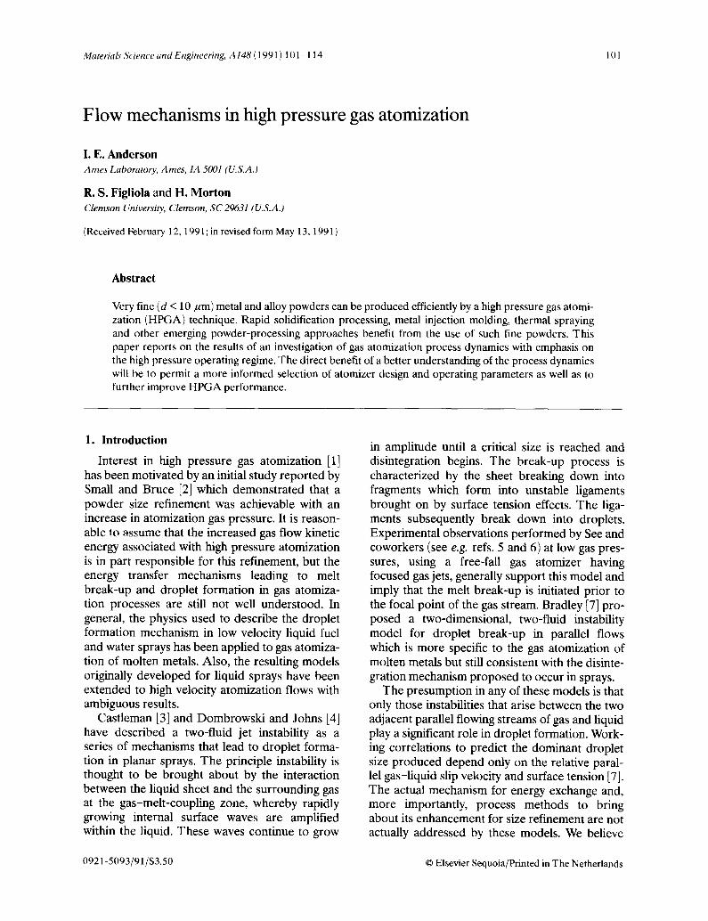
In conventional low and moderate pressure gas enhanced yield of fine powders can be achieved atomization practice, two types of nozzles are uti- with an increased mass flow ratio, but this effect lized. For applications where fine powder yields reaches a practical limit. With an economically are not critical, a free-fall or unconfined melt- dictated upper limit for atomization gas pressure feeding configuration is common, as Fig. l(a) using conventional technology fixed at about 5.5. illustrates. This free-fall configuration is charac- MPa, the melt flow rate must be decreased to terized by a gap of several centimeters between raise this ratio. Eventually, /'h m drops to a level the melt orifice at the bottom of the crucible or where melt stream freeze-off occurs. tundish and a concentric array of discrete gas jets. In fact, the increased refinement effect with In the free-fall gap the melt stream is free to increased rhJrh m also appears to reach a more wander or oscillate and initiates the break-up fundamental limit. Atomization experiments on instability, as noted by See and coworkers [5, 6]. iron alloys with an experimental AS-CF nozzle Because the melt stream cannot be centered reli- operated at 4.2 MPa [10] have shown that the ably with respect to the gas nozzle axis at the increased size refinement effect with increased point of gas impingement and because the break- ?/~/g/Fh m saturates. Specifically, the mass mean up instability and filming of the melt also cannot diameter asymptotically approaches a level of be controlled in this configuration, the free-fall about 20 ~m for rhg/rh m = 5 and remains un- nozzle is not a suitable candidate for develop- changed even for ratios as high as 14. ment of a high efficiency, high kinetic energy gas A more promising approach to achieving pro- nozzle, duction of fine powders with improved efficiency
A more efficient commercial approach [8] uti- appears to lie with a discrete jet atomization lizes an annular slit nozzle to supply atomization nozzle with the confined melt feed configuration gas and a confined melt feed configuration to feed (DJ-CF). Both the annular slit and discrete gas molten metal directly to the atomization zone, as jet nozzles employ a confined feed arrangement, shown in Fig. l(b). These annular slit-confined also termed "close coupled," which has long been feed (AS-CF) nozzles typically operate at moder- recognized for efficient transfer of the kinetic ate gas pressures of 4-5.5 MPa and produce the energy of the atomization gas to the melt stream commercial state-of-the-art yield of fine (dp < 44 [8]. Research by Anand et al. [11] using a DJ -CF ktm) powders [9]. Such an atomization gas pres- nozzle design, a so-called "ultrasonic" gas atomi- sure level has been viewed as a practical limit, in zation (USGA) nozzle, indicated that a more part because of the excessive rate of gas con- promising trend of decreased particle size with
increased gas pressure could be achieved through the use of elevated gas pressures beyond the corn-
METAL METAL mercial limit. Some early experimental results ;~ . . . . f ~ . ~ - ~ - - - - ~ ~ reported herein utilized the USGA nozzle design.
~( . / , . / / )~-~;"J ;~) However, later experiments employed a DJ -CF ~ ~ ~ : I t i ~ nozzle with an improved manifold and gas jet ~~ - ~ , ~ : ~ , ' , ~ , ' , design [12].
In this paper we show supporting evidence for our hypothesis that the efficiency of a gas atomi-
1~ zation process, i.e. the productivity of an atomi- zer for fine powder production, can be affected
FREE FALL CONFINED significantly by interactions of a supersonic gas Fig. 1. Atomizer nozzle geometries: (a) free-fall nozzle; (b) flOW with the melt. Th is hypothes i s shifts the anal- confined feed nozzle, ysis of atomization mechanisms to a more pro-
103
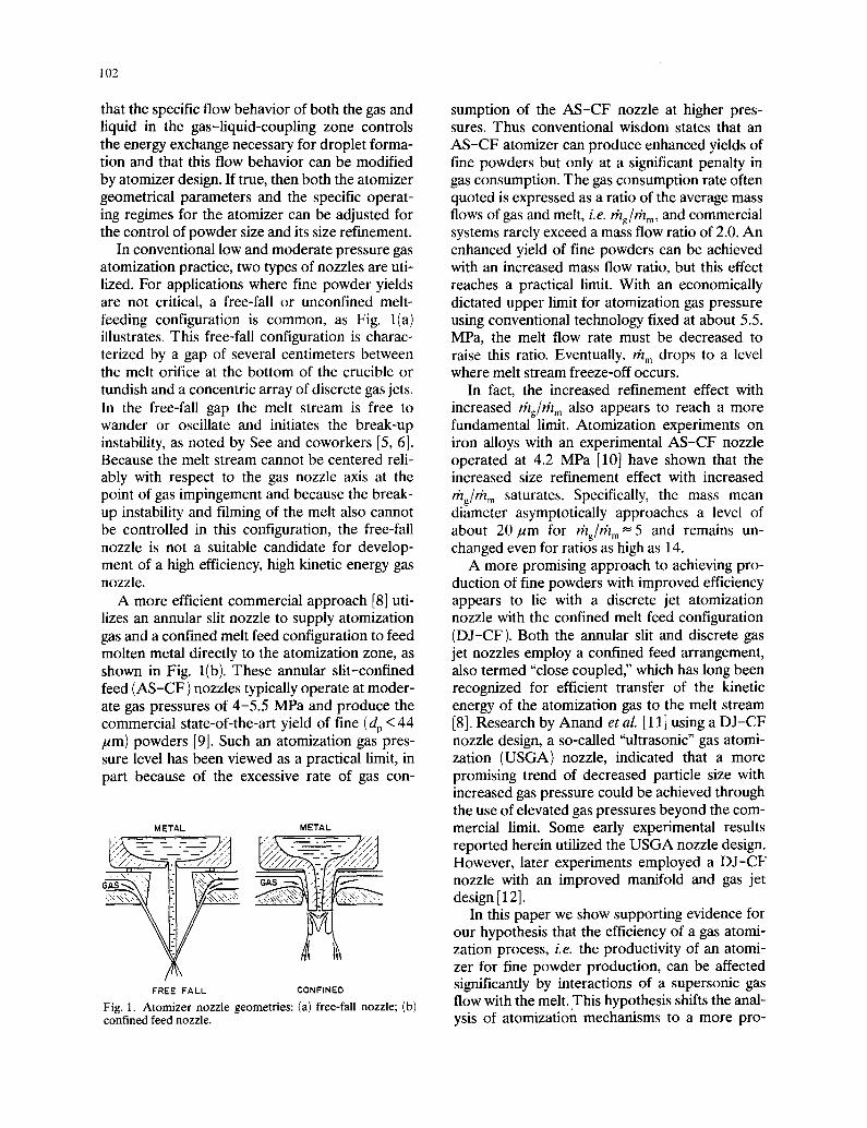
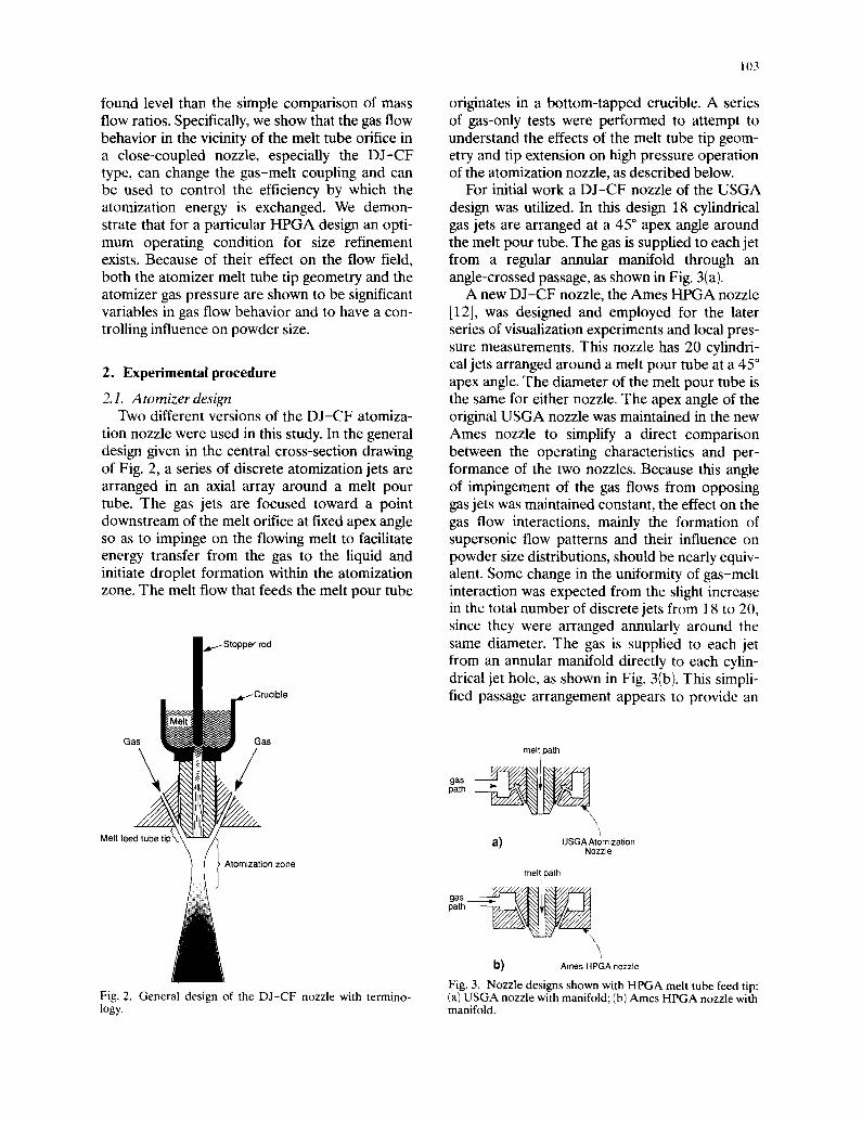
found level than the simple comparison of mass originates in a bottom-tapped crucible. A series flow ratios. Specifically, we show that the gas flow of gas-only tests were performed to attempt to behavior in the vicinity of the melt tube orifice in understand the effects of the melt tube tip geom- a close-coupled nozzle, especially the DJ-CF etry and tip extension on high pressure operation type, can change the gas-melt coupling and can of the atomization nozzle, as described below. be used to control the efficiency by which the For initial work a DJ-CF nozzle of the USGA atomization energy is exchanged. We demon- design was utilized. In this design 18 cylindrical strate that for a particular HPGA design an opti- gas jets are arranged at a 45 ° apex angle around mum operating condition for size refinement the melt pour tube. The gas is supplied to each jet exists. Because of their effect on the flow field, from a regular annular manifold through an both the atomizer melt tube tip geometry and the angle-crossed passage, as shown in Fig. 3(a). atomizer gas pressure are shown to be significant A new DJ-CF nozzle, the Ames HPGA nozzle variables in gas flow behavior and to have a con- [12], was designed and employed for the later trolling influence on powder size. series of visualization experiments and local pres-
sure measurements. This nozzle has 20 cylindri-
2. Experimental procedure cal jets arranged around a melt pour tube at a 45 ° apex angle. The diameter of the melt pour tube is
2. I. Atomizer design the same for either nozzle. The apex angle of the Two different versions of the DJ-CF atomiza- original USGA nozzle was maintained in the new
tion nozzle were used in this study. In the general Ames nozzle to simplify a direct comparison design given in the central cross-section drawing between the operating characteristics and per- of Fig. 2, a series of discrete atomization jets are formance of the two nozzles. Because this angle arranged in an axial array around a melt pour of impingement of the gas flows from opposing tube. The gas jets are focused toward a point gas jets was maintained constant, the effect on the downstream of the melt orifice at fixed apex angle gas flow interactions, mainly the formation of so as to impinge on the flowing melt to facilitate supersonic flow patterns and their influence on energy transfer from the gas to the liquid and powder size distributions, should be nearly equiv- initiate droplet formation within the atomization alent. Some change in the uniformity of gas-melt zone. The melt flow that feeds the melt pour tube interaction was expected from the slight increase
in the total number of discrete jets from 18 to 20, since they were arranged annularly around the
I , ~ . . J S t o p p e r r o d same diameter. The gas is supplied to each jet
from an annular manifold directly to each cylin- drical jet hole, as shown in Fig. 3(b). This simpli-
g,~, ~Crucible fied passage arrangement appears to provide an Gas'i:as k melt path
gas path
Melt feed tube tip- a) USGA Atomization Nozzle
Atomization zone melt path
path
\ \
b) Ames HPGA nozzle
Fig. 3. Nozzle designs shown with HPGA melt tube feed tip: Fig. 2. General design of the DJ -CF nozzle with termino- (a) USGA nozzle with manifold; (b) Ames HPGA nozzle with logy. manifold.
104
increased efficiency relative to the complex ~ ~ ~ ~ / . ~ , - . arrangement USGA design, as described in Section 3.
S ot/c ressuretes s The atomization of liquid metals using a high ,'/i ~ /
manifold gas pressure should result in a flow hav- ing a higher kinetic energy compared to low p r e s - ~ ~ j ~ ~ ~ z . sure operation. One should note that a problem can arise in high pressure atomizer operation when a static gas pressure near or above ambient
• . ~\\". J . \ x~ l / I exists at the melt tube orifice. Unless offset by a ,/,;"/' ' . . . . ', high metallostatic head or a pressurized crucible \\\,,', ,7, ~ ,,, ,,', / bath, a positive pressure at the melt orifice can
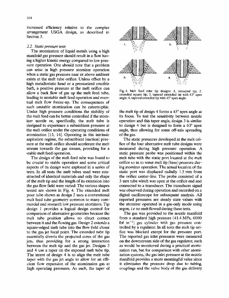
Fig. 4. Melt feed tube tip designs: 1, retracted tip; 2, allow a back flow of gas up the melt feed tube, extended square tip; 3, tapered extended tip with 63 ° apex leading to unstable melt feed operation and even- angle; 4, tapered extended tip with 45 ° apex angle. tual melt flow freeze-up. The consequences of such unstable atomization can be catastrophic. Under high pressure conditions the stability of the melt tip of design 4 forms a 45 ° apex angle at the melt feed can be better controlled if the atom- its focus. To test the sensitivity between nozzle izer nozzle or, specifically, the melt tube is operation and this taper angle, design 3 is similar designed to experience a subambient pressure at to design 4 but is designed to form a 63 ° apex the melt orifice under the operating conditions of angle, thus allowing for some off-axis spreading atomization [13, 14]. Operating in this intrinsic of the gas. aspiration regime, the subambient (suction) pres- The static pressures developed at the melt ori- sure at the melt orifice should accelerate the melt lice of the four alternative melt tube designs were stream towards the gas stream, providing for a measured during high pressure operation. A stable melt feed operation, static pressure probe was positioned within the
The design of the melt feed tube was found to melt tube with the static port located at the melt be crucial to stable operation and some critical orifice so as to sense melt tip (base) pressure dur- aspects of its design were explored in a series of ing atomizer operation. The actual location of the tests. In all tests the melt tubes used were con- static port was displaced radially 1.5 mm from structed of identical materials and only the shape the orifice center-line. The probe consisted of a of the melt tip and the length of its extension into 3 mm tube which was open at the orifice end and the gas flow field were varied. The various shapes connected to a transducer. The transducer signal tested are shown in Fig. 4. The extended melt was observed during operation and recorded on a pour tube shown as design 2 uses a conventional digital oscilloscope for subsequent analysis. All melt feed tube geometry common to many com- reported pressures are steady state values with mercial and research low pressure atomizers. Tip the atomizer operated in a gas-only mode using design 1 provides a logical design control for argon, i.e no melt flowed during these tests. comparison of alternative geometries because the The gas was provided to the nozzle manifold melt tube position allows no direct contact from a standard high pressure (41.4MPa, 6000 between it and the flowing gas. Design 2 extends a lbf in- 2) gas cylinder with gas pressure con- square-edged melt tube into the flow field closer trolled by a regulator. In all tests the melt tip ori- to the gas jet focal point. The extended tube tip rice was blocked except for the pressure port. essentially diverts the projected cores of the gas The reported gas inlet pressures were measured jets, thus providing for a strong interaction on the downstream side of the gas regulator, such between the melt tip and the gas jet. Designs 3 as would be monitored during a practical atomi- and 4 use a taper on the exposed melt tube tip. zation run, but for comparison with other atomi- The intent of design 4 is to align the melt tube zation systems, the gas inlet pressure at the nozzle taper with the gas jet angle to allow for an effi- manifold provides a more meaningful value since cient flow expansion of the atomization gas at it eliminates the pressure drop due to tubing, high operating pressures. As such, the taper of couplings and the valve body of the gas delivery
105
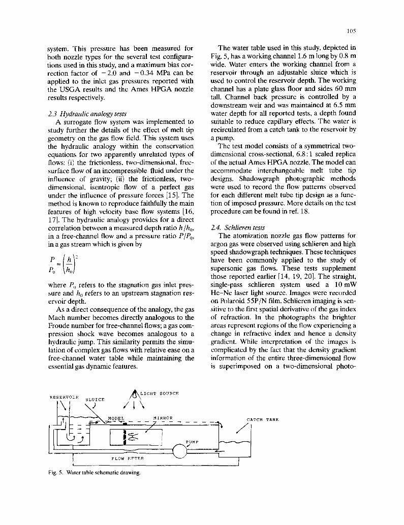
system. This pressure has been measured for The water table used in this study, depicted in both nozzle types for the several test configura- Fig. 5, has a working channel 1.6 m long by 0.8 m tions used in this study, and a maximum bias cor- wide. Water enters the working channel from a rection factor of - 2 . 0 and - 0 . 3 4 MPa can be reservoir through an adjustable sluice which is applied to the inlet gas pressures reported with used to control the reservoir depth. The working the USGA results and the Ames HPGA nozzle channel has a plate glass floor and sides 60 mm results respectively, tall. Channel back pressure is controlled by a
downstream weir and was maintained at 6.5 mm 2.3 Hydraulic analogy tests water depth for all reported tests, a depth found
A surrogate flow system was implemented to suitable to reduce capillary effects. The water is study further the details of the effect of melt tip recirculated from a catch tank to the reservoir by geometry on the gas flow field. This system uses a pump. the hydraulic analogy within the conservation The test model consists of a symmetrical two- equations for two apparently unrelated types of dimensional cross-sectional, 6.8:1 scaled replica flows: (i) the frictionless, two-dimensional, flee- of the actual Ames HPGA nozzle. The model can surface flow of an incompressible fluid under the accommodate interchangeable melt tube tip influence of gravity; (ii) the frictionless, two- designs. Shadowgraph photographic methods dimensional, isentropic flow of a perfect gas were used to record the flow patterns observed under the influence of pressure forces [15]. The for each different melt tube tip design as a func- method is known to reproduce faithfully the main tion of imposed pressure. More details on the test features of high velocity base flow systems [16, procedure can be found in ref. 18. 17]. The hydraulic analogy provides for a direct correlation between a measured depth ratio h/ho, 2.4. Schlieren tests in a free-channel flow and a pressure ratio P/Po, The atomization nozzle gas flow patterns for in a gas stream which is given by argon gas were observed using schlieren and high p (~ )2 speed shadowgraph techniques. These techniques
have been commonly applied to the study of P0 supersonic gas flows. These tests supplement
those reported earlier [14, 19, 20]. The straight, where P~ refers to the stagnation gas inlet pres- single-pass schlieren system used a 10 mW sure and h 0 refers to an upstream stagnation res- He-Ne laser light source. Images were recorded ervoir depth, on Polaroid 55P/N film. Schlieren imaging is sen-
As a direct consequence of the analogy, the gas sitive to the first spatial derivative of the gas index Mach number becomes directly analogous to the of refraction. In the photographs the brighter Froude number for free-channel flows; a gas corn- areas represent regions of the flow experiencing a pression shock wave becomes analogous to a change in refractive index and hence a density hydraulic jump. This similarity permits the simu- gradient. While interpretation of the images is lation of complex gas flows with relative ease on a complicated by the fact that the density gradient free-channel water table while maintaining the information of the entire three-dimensional flow essential gas dynamic features, is superimposed on a two-dimensional photo-
RESERVOIR SLUICE ~'kL/~\IGHT SOUPCE
\ /I\ " ~ l ~ - ~ MODEL MIRROR CATCH TANK
" -J, PUMP
, ( ~-
[ flow MZTER I
Fig. 5. Water table schematic drawing.
106
graph, prominent features of theflowfield remain trifugal dust separator and by retention in a intact, valved powder can, as shown in Fig. 6.
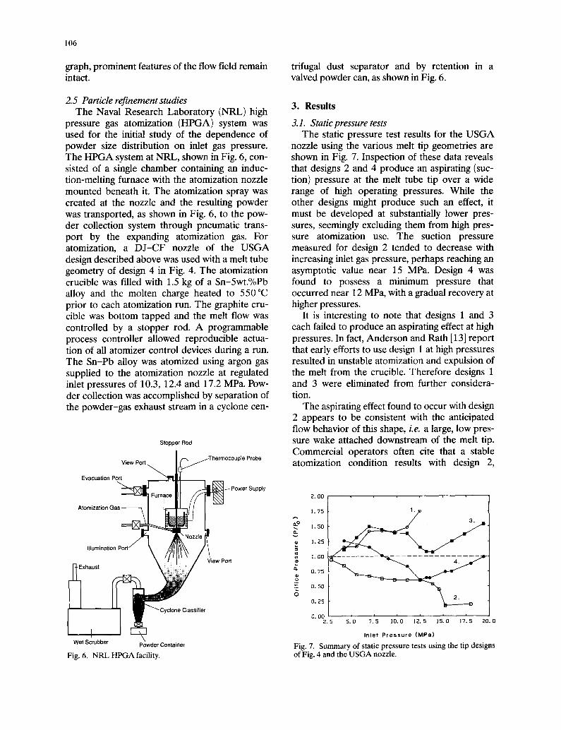
2.5 Particle refinement studies 3. Results The Naval Research Laboratory (NRL) high
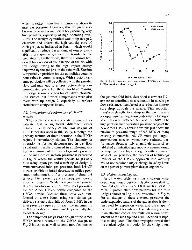
pressure gas atomization (HPGA) system was 3.1. Static pressure tests used for the initial study of the dependence of The static pressure test results for the U S G A powder size distribution on inlet gas pressure, nozzle using the various melt tip geometries are The HPGA system at NRL, shown in Fig. 6, con- shown in Fig. 7. Inspection of these data reveals sisted of a single chamber containing an induc- that designs 2 and 4 produce an aspirating (suc- tion-melting furnace with the atomization nozzle tion) pressure at the melt tube tip over a wide mounted beneath it. The atomization spray was range of high operating pressures. While the created at the nozzle and the resulting powder other designs might produce such an effect, it was transported, as shown in Fig. 6, to the pew- must be developed at substantially lower pres- der collection system through pneumatic trans- sures, seemingly excluding them from high pres- port by the expanding atomization gas. For sure atomization use. The suction pressure atomization, a DJ-CF nozzle of the USGA measured for design 2 tended to decrease with design described above was used with a melt tube increasing inlet gas pressure, perhaps reaching an geometry of design 4 in Fig. 4. The atomization asymptotic value near 15 MPa. Design 4 was crucible was filled with 1.5 kg of a Sn-5wt.°/ePb found to possess a minimum pressure that alloy and the molten charge heated to 550 °C occurred near 12 MPa, with a gradual recovery at prior to each atomization run. The graphite cru- higher pressures. cible was bottom tapped and the melt flow was It is interesting to note that designs 1 and 3 controlled by a stopper rod. A programmable each failed to produce an aspirating effect at high process controller allowed reproducible actua- pressures. In fact, Anderson and Rath [13] report tion of all atomizer control devices during a run. that early efforts to use design 1 at high pressures The Sn-Pb alloy was atomized using argon gas resulted in unstable atomization and expulsion of supplied to the atomization nozzle at regulated the melt from the crucible. Therefore designs 1 inlet pressures of 10.3, 12.4 and 17.2 MPa. Pew- and 3 were eliminated from further considera- der collection was accomplished by separation of tion. the powder-gas exhaust stream in a cyclone cen- The aspirating effect found to occur with design
2 appears to be consistent with the anticipated flow behavior of this shape, i.e. a large, low pres-
Stopper Rod sure wake attached downstream of the melt tip. Commercial operators often cite that a stable
View Port~ ~ThermocoupleProbe atomization condition results with design 2, ~ x
Inlet Pressure (MPa) Wet Scrubber Powder Container Fig. 7. Sununary of static pressure tests using the tip designs
Fig. 6. NRL HPGA facility, of Fig. 4 and the USGA nozzle.
10 7
which is rather insensitive to minor variations in 1.2 , , inlet gas pressure. However, this design is also ----cv- ^m,s . . . . ~.
zzle known to be rather inefficient for producing very t.0 fine powders, especially at high operating pres- sures. The straight cylindrical wall of tip design 2 obstructs and diverts the high velocity core of ~ 0.a each gas jet, as indicated in Fig. 4, which would ~, significantly reduce the amount of energy avail- 8. 0.6[ able in the atomization zone for transfer to the melt stream. Furthermore, there is a known ten- = O 0.4 dency for erosion of the exterior of the tip with this design owing to the high impact energy imparted by the gas jets on the tube wall. Erosion 0.2 ' ' ' 5 10 15 20 is especially a problem for the monolithic ceramic pour tubes in common usage. With erosion, cer- Inlet Pressure (MPa) amic particulate will be collected with the powder Fig. 8. Static pressure test comparison: USGA and Ames yield and may lead to microstructure defects in HPGA nozzles with tip design 4. consolidated parts. For these two basic reasons, tip design 4 was selected for extensive atomiza- tion studies, but further comparisons were also the gas manifold inlet, described elsewhere [12], made with tip design 2, especially to explore appear to contribute to a reduction in nozzle gas atomization energetics issues, flow resistance, manifested as a reduction in pres-
sure drop through the nozzle. This reduction 3.2. Comparison of performance of DJ-CF translates directly to a drop in the gas pressure nozzles for optimum disintegration performance by argon
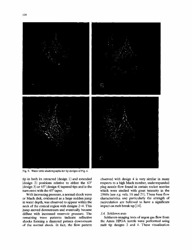
The results of a series of static pressure tests atomization to between 6.9 and 7.6 MPa. The indicate that a significant difference exists high performance operating pressure range of the between the efficiency of the two designs of new Ames HPGA nozzle now falls just above the DJ-CF nozzles used in this study, although the maximum pressure range of 5.5 MPa of many primary features of their operation in the HPGA existing commercial AS-CF inert gas (argon) regime is remarkably similar. The similarity in atomization nozzles which have reduced per- operation is further demonstrated in gas flow formance. Because only a small elevation of es- visualization results discussed in a following sec- tablished atomization gas supply pressures would tion. A summary of the effect of gas inlet pressure be required to achieve a significantly enhanced on the melt orifice suction pressure is presented yield of fine powders, the process of technology in Fig. 8, where the results pertain to gas-only transfer of the HPGA approach into industry flow using argon gas and a melt tip of design 4. would not require a major change in safety limits With increased inlet gas pressure, both DJ -CF on the part of powder plant design engineers. nozzles exhibit an initial decrease in orifice pres- sure, a minimum in orifice pressure of about 0.4 3.3. Hydraulic analogy tests times ambient pressure and a subsequent increase In all water table tests the upstream water in orifice pressure. While their trends are similar, depth was varied between depths equivalent to there is an obvious shift to lower inlet pressures manifold gas pressures of 1.8 through at least 10 for the Ames HPGA nozzle compared to the MPa. Representative flow patterns for the four USGA nozzle. Because these tests were per- designs shown in Fig. 4 are presented in Fig. 9. formed on a test bench using very similar gas For all designs at these elevated pressures the delivery systems, this shift of about 5 MPa in gas underexpanded nature of the gas jet flow is dem- inlet pressure required to reach the minimum in onstrated by expansion waves and the shape of melt tube orifice pressure must be principally due the external jet boundaries. Each design gives rise to nozzle design, to an attached conical recirculation region down-
The simplified gas passage design of the Ames stream of the melt tip and a well-defined dissipa- HPGA nozzle relative to the USGA design, as tive mixing later. The shadowgraphs reveal that Fig. 3 indicates, as well as some modifications to the conical region is broader for the straight melt
108
Fig. 9. Water table shadowgraphs for tip designs of Fig. 4.
J
, - <
tip in both its retracted (design 1) and extended observed with design 4 is verysimilar in many (design 2) positions relative to either the 63 ° respects to a high Mach number, underexpanded (design 3) or 45 ° (design 4) tapered tips and is the plug nozzle flow found in certain rocket nozzles narrowest with the 45°taper. which were studied with great intensity in the
With increasing pressure, a normal shock wave 1960s (see e.g. refs. 16 and 21). These base flow or Mach disk, evidenced as a large sudden jump characteristics and particularly the strength of in water depth, was observed to appear within the recirculation are believed to have a significant neck of the conical region with designs 2-4. This impact on melt break-up [14]. jump moved downstream and eventually became diffuse with increased reservoir pressure. The 3.4. Schlieren tests remaining wave patterns indicate reflective Schlieren-imaging tests of argon gas flow from shocks forming a diamond pattern downstream the Ames HPGA nozzle were performed using of the normal shock. In fact, the flow pattern melt tip designs 2 and 4. These visualization
I I J ' J
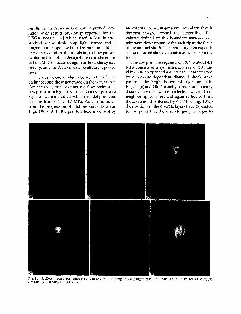
results on the Ames nozzle have improved reso- an external constant-pressure boundary that is lution over results previously reported for the directed inward toward the center-line. The USGA nozzle [14] which used a less intense volume defined by this boundary narrows to a strobed xenon flash lamp light source and a minimum downstream of the melt tip at the focus longer shutter-opening time. Despite these differ- of the internal shock. The boundary then expands ences in resolution, the trends in gas flow pattern as the reflected shock emanates outward from the evolution for melt tip design 4 are reproduced for focus. either DJ-CF nozzle design. For both clarity and The low pressure regime from 0.7 to about 4.1 brevity, only the Ames nozzle results are reported MPa consists of a symmetrical array of 20 indi- here. vidual underexpanded gas jets each characterized
There is a close similarity between the schlier- by a pressure-dependent diamond shock wave en images and those generated on the water table, pattern. The bright horizontal layers noted in For design 4, three distinct gas flow regimes--a Figs. 10(a)and 10(b)actually correspond to many low pressure, a high pressure and an overpressure discrete regions where reflected waves from regime--were identified within gas inlet pressures neighboring jets meet and again reflect to form ranging from 0.7 to 17 MPa. As can be noted these diamond patterns. By 4.1 MPa (Fig. 10(c)) from the progression of inlet pressures shown as the positions of the discrete layers have expanded Figs. 10(a)-10(f), the gas flow field is defined by to the point that the discrete gas jets begin to
Fig. 10. Schlieren results for Ames HPGA nozzle with tip design 4 using argon gas: (a) 0.7 MPa; (b) 2.1 MPa; (c) 4.1 MPa; (d) 6.9 MPa; (e) 9.0 MPa; (f) 13.1 MPa.
1 I 0
merge into a unified flow field. Using the diame- and differences in the highly energetic, compres- ter of the melt tip, B, as a reference length, it can sible gas flows generated by these two different be seen that an abrupt increase in gas density designs for an HPGA nozzle. This suggests a develops along the horizontal plane located at strong relationship between melt tube tip design distance B downstream of the melt tip orifice, and its resulting flow field under high pressure Coincident with this position is the minimum in operation. The schlieren results complement the the volume defined by the external boundary, static pressure results. For the 45 ° apex angle Also apparent, the apex of axisymmetric reflected design the aspirating effect occurs at gas inlet shock waves is located at 2.3B. pressures residing in the high pressure flow
The high pressure regime was observed for regime, a flow regime that is represented by very inlet gas pressures over the range of 6.2-10.3 distinct flow characteristics. The taper angle asso- MPa. In the gas flows at these pressures a normal ciated with this design allows the supersonic gas circular shock wave or Mach disk becomes flow to persist along the length of the melt tip and apparent and is located at the minimum in the without any significant loss of energy to the volume defined by the external boundary. That is, melt tip through direct impingement. From it is formed at the focus of the incident shock momentum considerations the aspirating effect wave. As demonstrated in Figs. 10(d) and 10(e), also requires the presence of a gas recirculation the position of the Mach disk moves downstream region attached to the melt tip. with increased inlet pressure from B to 1.55B. Gas recirculation could play a significant role The external jet boundary becomes the most con- in energy transfer and droplet break-up in HPGA stricted in this range of pressures. The reflected by forcing the melt to flow radially outward, car- shock waves downstream of the Mach disk rying it toward contact with the high velocity gas remain visible, flow, a mechanism initially described and sup-
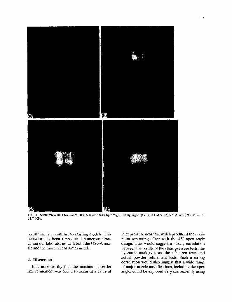
The overpressure regime was observed at ported in ref. 14. Secondary disintegration could pressures beyond 11 MPa. As characterized in also occur as the droplets pass through the focal Fig. 10(f), the Mach disk has dissipated in this region containing the Mach disk, but this could regime, the interior of the unified flow field devel- not be verified. A model of the gas flow field has ops a low density core below the incident shock been constructed in Fig. 12. reflections and the external boundary becomes nearly vertical without the constriction noted at 3.5. Powder refinement tests lower inlet pressures. The results of the powder-processing tests [ 13]
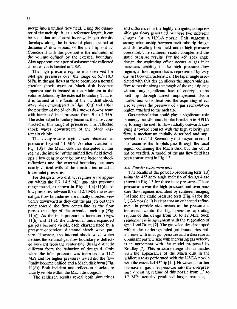
For design 2, two distinct regimes were appar- using the 45 ° apex angle melt tip of design 4 are ent within the 0.7-14.5 MPa gas inlet pressure shown in Fig. 13 for three inlet pressures. These range tested, as shown in Figs. l l (a ) - l l (d ) . At pressures cover the high pressure and overpres- low pressures between 0.7 and 2.1 MPa the exter- sure flow regimes identified by schlieren imaging nal gas flow boundaries are initially directed ver- [14] and the static pressure tests (Fig. 8) for the tically downward as they exit the gas jets but then USGA nozzle. It is clear that an enhanced refine- bend toward the flow center-line as the flow ment in particle size occurs as the pressure is passes the edge of the extended melt tip (Fig. increased within the high pressure operating ll(a)). As the inlet pressure is increased (Figs. regime of this design from 10 to 12 MPa. Such 1 l(b) and 1 l(c), the individual underexpanded refinement is in agreement with the suggestion of gas jets become visible, each characterized by a Small and Bruce [2]. The gas velocities developed pressure-dependent diamond shock wave pat- within the underexpanded jet boundaries will tern. However, the internal shock wave which increase with inlet gas pressure and a decrease in defines the external gas flow boundary is deflect- dominant particle size with increasing gas velocity ed outward from the center-line; this is distinctly is in agreement with the model proposed by different from the behavior of design 4. Only Bradley [7]. This pressure range also coincides when the inlet pressure was increased to 11.7 with the appearance of the Mach disk in the MPa and for higher pressures tested did the flow schlieren tests performed with the USGA nozzle finally become unified and a Mach disk form (Fig. with the extended 45 ° tip [14]. However, a further ll(d)). Both incident and reflection shocks are increase in gas inlet pressure into the overpres- clearly visible within the Mach disk region, sure operating regime of this nozzle from 12 to
The schlieren results reveal both similarities 17 MPa actually produced larger particles, a
III
Fig. 1 1. Schlieren results for Ames HPGA nozzle with tip design 2 using argon gas: (a) 2.1 MPa; (b) 5.5 MPa; (c) 9.7 MPa; (d) 11.7 MPa.
result that is in contrast to existing models. This inlet pressure near that which produced the maxi- behavior has been reproduced numerous times mum aspirating effect with the 45 ° apex angle within our laboratories with both the USGA noz- design. This would suggest a strong correlation zle and the more recent Ames nozzle, between the results of the static pressure tests, the
hydraulic analogy tests, the schlieren tests and 4. Discussion actual powder refinement tests. Such a strong
correlation would also suggest that a wide range It is note worthy that the maximum powder of major nozzle modifications, including the apex
size refinement was found to occur at a value of angle, could be explored very conveniently using
112
~ - IN = t: ~ RECOMPRESSION
~ ' . ~ . ~ : : / recir?ulaUon flow and ~ F / ~ ' ~ ~ ~'4-e "~'~'~'~ / /".~:.:" ( :! :.": ~ initial b r e a k u p . ~ / / / / / / / / / ~ ~ _ ~ _ ~ _ ~ ~ / / J ~ A C H DtSC " ~
/,t , I I I / / ," / . ' J . . ~
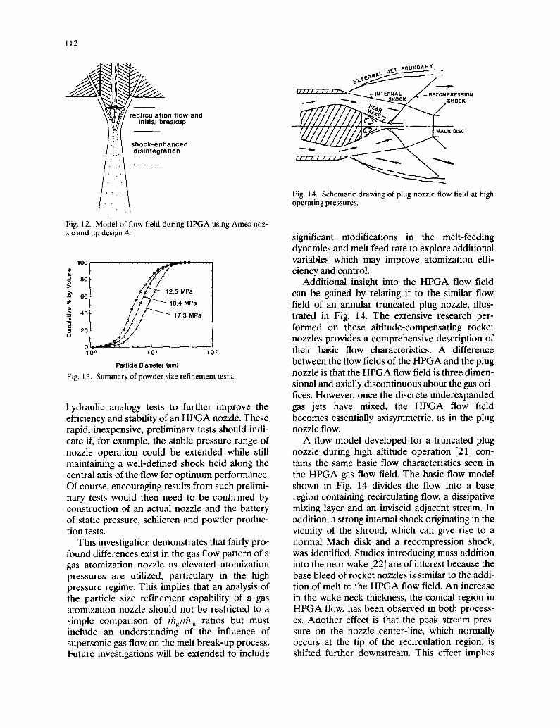
Fig. ] 4. Schematic drawing of plug nozzle flow field at high operating pressures.
Fig. 12. Model of flow field during HPGA using Ames noz- zle and tip design 4. significant modifications in the melt-feeding
dynamics and melt feed rate to explore additional lOO . . . . . . . . . . , .,,---- . . . . . . variables which may improve atomization effi-
v ~ / " ciency and control. 80 ~ 1 2 . s u Additional insight into the HPGA flow field eo lo.4 upPaa can be gained by relating it to the similar flow
/! field of an annular truncated plug nozzle, illus- .~ 40 / / . / - tr.3 UPa trated in Fig. 14. The extensive research per-
20 = ~ / formed on these altitude-compensating rocket o nozzles provides a comprehensive description of
°oo- ~0 -'=~' ' - ' ' " , . . . . . . . 10, their basic flow characteristics. A difference Particle Diameter (~lm) between the flow fields of the HPGA and the plug
nozzle is that the HPGA flow field is three dimen- Fig. 13. Summary of powder size refinement tests. sional and axially discontinuous about the gas ori- fices. However, once the discrete underexpanded
hydraulic analogy tests to further improve the gas jets have mixed, the HPGA flow field efficiency and stability of an HPGA nozzle. These becomes essentially axisymmetric, as in the plug rapid, inexpensive, preliminary tests should indi- nozzle flow. cate if, for example, the stable pressure range of A flow model developed for a truncated plug nozzle operation could be extended while still nozzle during high altitude operation [21] con- maintaining a well-defined shock field along the tains the same basic flow characteristics seen in central axis of the flow for optimum performance, the HPGA gas flow field. The basic flow model Of course, encouraging results from such prelimi- shown in Fig. 14 divides the flow into a base nary tests would then need to be confirmed by region containing recirculating flow, a dissipative construction of an actual nozzle and the battery mixing layer and an inviscid adjacent stream. In of static pressure, schlieren and powder produc- addition, a strong internal shock originating in the tion tests, vicinity of the shroud, which can give rise to a
This investigation demonstrates that fairly pro- normal Mach disk and a recompression shock, found differences exist in the gas flow pattern of a was identified. Studies introducing mass addition gas atomization nozzle as elevated atomization into the near wake [22] are of interest because the pressures are utilized, particulary in the high base bleed of rocket nozzles is similar to the addi- pressure regime. This implies that an analysis of tion of melt to the HPGA flow field. An increase the particle size refinement capability of a gas in the wake neck thickness, the conical region in atomization nozzle should not be restricted to a HPGA flow, has been observed in both process- simple comparison of /7~/g//T/m ratios but must es. Another effect is that the peak stream pres- include an understanding of the influence of sure on the nozzle center-line, which normally supersonic gas flow on the melt break-up process, occurs at the tip of the recirculation region, is Future investigations will be extended to include shifted further downstream. This effect implies
113
that the recirculation region of the HPGA flow authors acknowledge the support of Ames Lab- field can be expected to lengthen somewhat as oratory, Iowa State University, the BES-Mater- liquid melt is introduced, ials Science Division of the U.S. Department of
Energy, and Clemson University.
5. Conclusions
An experimental investigation into the flow References mechanisms associated with melt break-up in high pressure gas atomization has been reported. I J. D. Ayers and 1. E. Anderson, Method for generating An improvement in nozzle operating efficiency in fine sprays of molten metal for spray coating and powder
making, U.S. Patent 4,619,845, 1986. the high pressure regime was demonstrated 2 S. Small and T. J. Bruce, The comparison of charac- through nozzle design modifications. The effect teristics of water and inert gas atomized powders, Int. J. of melt tube tip geometry on the resulting atom- Powder Metall., 4 (3) (1968) 7-17. izer gas flow field was also studied. It was shown 3 R.A. Castleman, J. Res. NBS, 6(1931)369. that the melt tube tip geometry plays a significant 4 N. Dombrowski and W. Johns, The aerodynamic instabil-
ity and disintegration of viscous liquid sheets, Chem. role in determining the resulting HPGA flow Eng. Sci., 18(19631203-214. field. Specifically, for optimum performance in 5 J. B. See, J. Runkle and T. B. King, The disintegration of the HPGA operation regime the exterior surfaces liquid lead streams by nitrogen jets. Metall. Trans., 4 of the nozzle feed tube should align exactly with (1973) 2669-2673. the interior dimension of the discrete jet array. 6 J. See and G. Johnston, Powder Technol., 21 (1978) 119.
7 D. Bradley, On the atomization of a liquid by high veloc- Further, the taper of the feed tube should match ity gases, parts 1 and 2, J. l'hys. D: Appl. Phys., 6 (1973) the extended flow direction of the high energy 1724-1736, 2267-2272. cores of the gas jets, i.e. the interior of the super- 8 J. s. Thompson, A study of process variables in the pro- sonic gas flow "curtain." These tight geometric duction of aluminum powder by atomization, J. Inst.
constraints minimize gas flow energy losses in the Met., 74(1948) 101-132. short free-expansion region along the exterior of 9 A. Lawley, An overview of powder atomization pro-
cesses and fundamentals, Int. J. Powder Metall. Powder the feed tube tip and thereby promote the persis- Technol., 13 (31(1977) 169-188. tence of supersonic laminar gas flow all the way 10 S. Miller, General Electric Co., Schnectady, NY, personal to the point of first impact of the gas with the communication to I. Anderson at Naval Research
melt. These effects ensure the maximization of Laboratory, 1984. atomization energy transfer in the initial atomiza- 11 v. Anand, A. J. Kaufman and N. Grant, Rapid solidifica-
tion of a modified 7(175 alumium alloy by ultrasonic gas tion event at the edge of the pour tube and en- atomization, in R. Mehrabian, B. H. Kear and M. Cohen courage the full development of an intense Mach (eds.) Rapid Solidification Processing, l'rinciples and
shock disk which may also perform an effective Technologies, I1, Claitor, Baton Rouge, LA, 1978, pp. secondary atomization function. 273-286.
The physical extension of the melt feed tube 12 1. Anderson, R. S. Figliola and H. Morton Molnar, Improved atomizing nozzle and process, Registered U.S.
tip into the atomization region can produce an Patent Pending, 199(J. aspiring effect that can stabilize melt feed and 13 I. E. Anderson and B. B. Rath, Rapid solidification of generate a strong recirculation region. Under copper based alloys, in S. K. Das, B. H. Kear and C. M. proper conditions an intense downstream normal Adam (eds.) Rapidly Solidified Crystalline Alloys, TMS-
AIME, Warrendale, PA 1985, pp. 219-244. shock disk can appear which was correlated to 14 I. E. Anderson and R. S. Figliola, Observations of gas the measurements of a maximum in nozzle aspi- atomization process dynamics, in P. U. Gummeson and ration effect. For one design tested, an optimum D.A. Gustafson (eds.), Modern Developments in Powder operating condition was found to occur which Metallurgy, American Powder Metallurgy Institute, was shown to be correlated to particle size refine- Princeton, N J, 1988, pp. 205-223. m e n t . 15 A. H. Shapiro, Free surface water table, in R.
Landenburg, B. Lewis, R. Pease and H. Taylor (eds.), Physical Measurements in Gas Dynamics and Combus- tion, Vol. 9, Princeton University Press, Princeton, N J,
Acknowledgments 1954, pp. 309-321.
One of the authors (LEA.) would like to 16 R. H. Page and A. P. Meyer, Hydraulic analog investiga- tion of a plug nozzle, Am. Rocket Soc. J., 31 (3) (1961)
acknowledge the support received at the U.S. 447 448.
Naval Research Laboratory where some of the 17 Studying transonic gases with a hydraulic analog, NASA gas atomization research was performed. The Tech. Briefs, MFS-19100, 1979.
114
18 H. Morton, Flow mechanisms of the high pressure gas 20 J. D. Ayers and 1. E. Anderson, Very fine metal powders, atomization process revealed by flow visualization, M.S. J. Met., 37 (August 1985) 16-21. Thesis, Clemson University, 1990. 21 W. P. Sule and T. J. Mueller, Annular truncated plug
19 R. S. Figliola, I. E. Anderson and H. Morton, Flow nozzle flowfield and base pressure characteristics, measurements in gas atomization processes, in Synthesis J. Spacecraft, 10 ( 11 ) (1983) 521-525. and Analysis in Materials and Processing,: Advances in 22 D. Collines, L. Lees and A. Roshko, Near wake of a Characterization and Diagnosis of Ceramic and Metal hypersonic blunt body with mass additions, AIAA J., Particulate Processing, TMS, Warrendale, PA, 1989, pp. 8 (5) (1970) 833-842. 39-47.