FOR VEHICLES FITTED WITH CNG FUEL SYSTEM 69RM0-74E CONTENTS INTRODUCTION TO CNG..................................................................................... 1 SAFETY PRECAUTIONS (Do’s and Don’ts) ...................................................... 1 LAYOUT OF THE CNG SYSTEM.......................................................................... 2 FUEL MODES ....................................................................................................... 3 SELECTOR SWITCH POSITION ......................................................................... 3 PETROL MODE..................................................................................................... 3 AUTO MODE ........................................................................................................ 3 FORCED CNG MODE .......................................................................................... 4 CNG LEVEL INDICATOR ..................................................................................... 4 AUTOMATIC CHANGEOVER FROM CNG MODE TO PETROL MODE............. 4 CNG FILLER VALVE............................................................................................. 5 CNG CYLINDER.................................................................................................... 5 CNG CYLINDER WARNING LABEL .................................................................... 5 MANUAL SHUT-OFF VALVE ............................................................................... 6 LIST OF GOVERNMENT APPROVED CNG CYLINDER TESTING STATIONS ........................................................................ 7 SPARE TYRE REPLACEMENT ........................................................................... 7 KIT IDENTIFICATION ........................................................................................... 8 CNG WARNING LABEL........................................................................................ 9 INSTRUMENT CLUSTER ................................................................................... 10 CNG MALFUNCTION WARNING LAMP ............................................................ 10 CNG LOW FUEL WARNING LIGHT .................................................................. 11 FUSES................................................................................................................. 11 PERIODIC MAINTENANCE SCHEDULE .......................................................... 13 SPECIFICATIONS............................................................................................... 14 FIRE EXTINGUISHER (if equipped) .................................................................. 15
Transcript
FOR VEHICLES FITTED WITH CNG FUEL SYSTEM
69RM0-74E
CONTENTS INTRODUCTION TO CNG..................................................................................... 1SAFETY PRECAUTIONS (Do’s and Don’ts) ...................................................... 1LAYOUT OF THE CNG SYSTEM.......................................................................... 2FUEL MODES ....................................................................................................... 3SELECTOR SWITCH POSITION ......................................................................... 3PETROL MODE..................................................................................................... 3AUTO MODE ........................................................................................................ 3FORCED CNG MODE .......................................................................................... 4CNG LEVEL INDICATOR ..................................................................................... 4AUTOMATIC CHANGEOVER FROM CNG MODE TO PETROL MODE............. 4CNG FILLER VALVE............................................................................................. 5CNG CYLINDER.................................................................................................... 5CNG CYLINDER WARNING LABEL .................................................................... 5MANUAL SHUT-OFF VALVE ............................................................................... 6LIST OF GOVERNMENT APPROVED CNG CYLINDER TESTING STATIONS ........................................................................ 7SPARE TYRE REPLACEMENT ........................................................................... 7KIT IDENTIFICATION ........................................................................................... 8CNG WARNING LABEL........................................................................................ 9INSTRUMENT CLUSTER ................................................................................... 10CNG MALFUNCTION WARNING LAMP ............................................................ 10CNG LOW FUEL WARNING LIGHT .................................................................. 11FUSES................................................................................................................. 11PERIODIC MAINTENANCE SCHEDULE .......................................................... 13SPECIFICATIONS............................................................................................... 14FIRE EXTINGUISHER (if equipped) .................................................................. 15
1
FOR VEHICLES FITTED WITH CNG FUEL SYSTEM
69RM0-74E
INTRODUCTION TO CNG:CNG (Compressed Natural Gas) mainlycontains methane. CNG is considered as aclean burning fuel. Due to low density ofCNG, it is compressed at a pressure ofaround 200 bars to enhance the vehicleon-board storage capacity.
SAFETY PRECAUTIONS (Do’s)1. If any service or body repair is to be
carried out, turn the manual shut offvalve on CNG cylinder valve to closeposition prior to commencement of therepair work.
2. Get the CNG cylinder checked everythree (3) years from the date of lasttesting / retesting of cylinder by govern-ment authorised CNG cylinder testingagency.
3. If the vehicle does not changeover toCNG in AUTO MODE, then have yourvehicle checked by Maruti Suzukiauthorised workshop at the earliest.
4. Switch “OFF” engine while filling thefuel (CNG/Petrol).
5. After refueling CNG or Petrol, ensurethat the fuel filler lid is closed. (Other-wise vehicle cannot be started)
6. In AUTO MODE, the system is pro-grammed to start the vehicle in petroland automatically shift to CNG basedon engine temperature & other parame-ters. Do not press the accelerator pedalto change from petrol to CNG.
SAFETY PRECAUTIONS (Don’ts):1. Do not change/modify the configura-
tion, settings or the components fromCNG system.
2. The CNG cylinder should not berepaired under any circumstances. Incase of any problem, consult withMaruti Suzuki authorised workshop.
3. Do not adjust setting of CNG system.4. Never install LPG or any other gas cyl-
inder in place of CNG cylinder.5. Avoid carrying inflammable material
near the CNG cylinder.6. Do not fill any gas other than CNG.7. Do not press the accelerator pedal to
change from petrol to CNG MODE.
CAUTION
In case of any symptom of CNG leak-age or releasing noise or any externaldamage to CNG piping or duringaccident, do not panic.• Stop the vehicle and switch off
the engine, roll down the win-dows and open all the doors
• Ensure to close manual shut offvalve.
• Contact Maruti Suzuki authorisedworkshop immediately for furtherassistance.
(10) Low pressure & temperature sensor(11) Low pressure CNG hose (Chamber to rail)(12) Pressure regulator
(13) Water hose(14) High pressure sensor(15) High pressure gauge(16) CNG filter(17) Low pressure CNG hose (filter to chamber)(18) CNG hose Chamber
3
FOR VEHICLES FITTED WITH CNG FUEL SYSTEM
69RM0-74E
FUEL MODESThere are three fuel modes in the vehicle(Petrol, Auto and Forced CNG) which areselectable by pressing the selector switch(1) located on the right side of the steeringwheel on the dashboard.
NOTE:• Do not press the accelerator pedal to
changeover from petrol to CNG mode.
• With ignition switch "ON" and engine notrunning, blinking of CNG malfunctionwarning lamp indicates that fuel lid isopen. Vehicle will not start in this condi-tion. For details on CNG malfunctionwarning lamp, refer to “Instrument clus-ter” section in this manual.
SELECTOR SWITCH POSITION
69RM0010
PETROL MODE
69RM0001
In this mode vehicle starts in petrol andcontinues to run in petrol mode. In this
mode, petrol indicator is continuously dis-played and CNG indicator will remain“OFF”.
AUTO MODE
69RM0002
In this mode engine starts in petrol modeand then automatically changes to CNGmode after reaching programmed warmingup condition. With ignition switch ON andvehicle started in “AUTO MODE”, CNGindicator blinks on the display and PET-ROL indicator is displayed. After change-over to CNG, CNG indicator will bedisplayed and Petrol indicator will switchOFF automatically.
NOTE:• It is always recommended to start the
vehicle in AUTO MODE or PETROLMODE to enhance the engine life.
• The fuel changeover to CNG may nothappen if the vehicle is started when theambient / engine temperature is belowZero Degree Celsius. In such a case,run the engine in PETROL MODE till itwarms up and then try restarting theengine to changeover to CNG.
WARNING
Make sure that the parking brake isapplied fully and the transmission isin Neutral before attempting to startthe engine.
NOTICE
• For protection of a lead-acid bat-tery and a starter motor, if you usethe starter motor by turning the keyto “START” for more than 12 sec-onds at a time, the starter motorstops automatically. Turn the key to“LOCK” position and wait for morethan 30 seconds before tryingagain. If the engine does not startafter several attempts, check thefuel and ignition system or consulta Maruti Suzuki authorised work-shop.
• If the engine starts, the startermotor stops automatically.
CNG
FUEL
EXAMPLE
EXAMPLE
EXAMPLE
4
FOR VEHICLES FITTED WITH CNG FUEL SYSTEM
69RM0-74E
FORCED CNG MODE
69RM0003
This is an emergency mode and may beused in cases where there is no petrol inthe petrol tank. In this mode vehicle startsin CNG mode and continues running inCNG mode.With ignition “ON” and enginenot running, press and hold the change-over switch till only CNG indicator is dis-played. In this mode, CNG indicator isdisplayed and Petrol indicator remains“OFF”.
NOTE:• It is recommended to keep sufficient
amount of petrol in the petrol tank.• The vehicle may not start in Forced CNG
mode if the ambient / engine tempera-ture is below Zero Degree Celsius. It isrecommended to start the vehicle inAuto mode.
CNG LEVEL INDICATOR
69RM0029
CNG level indicator (1) is built into the dis-play. When the ignition switch is in the“ON” position, this gauge gives an approxi-mate indication of the quantity of CNG fuelin the CNG tank. “F” stands for full and “E”stands for empty.If the CNG level meter indicator showsonly one segment to “E” refill the CNG tankas soon as possible.
NOTE:If the last segment blinks, it means that thefuel is almost empty.If the CNG low fuel warning light (3) comeson, fill the CNG tank immediately.
The mark (2) indicates that the fuel fillerdoor is located on the left side of the vehi-cle.
AUTOMATIC CHANGEOVER FROM CNG MODE TO PETROL MODEIf CNG is finished while the engine is run-ning, vehicle will automatically changeoverfrom CNG mode to Petrol mode & CNGmalfunction warning lamp will start blink-ing. Petrol indicator will be displayed con-tinuously and CNG indicator will switchOFF automatically.To acknowledge this information, press thechangeover switch once. The CNG mal-function warning lamp will stop blinkingafter the changeover switch is pressed andpetrol indicator will be displayed continu-ously. However the CNG malfunction indi-cator lamp will continue to blink after everysubsequent Ignition ON - Ignition OFF con-dition until the vehicle is refilled with CNG.
NOTE:• It is recommended to keep sufficient
amount of petrol in the petrol tank to pre-vent engine stalling while automaticchangeover from CNG mode to Petrolmode.
• In case the CNG malfunction warninglamp does not stop blinking after press-ing the changeover switch, take the vehi-cle to the nearest Maruti Suzukiauthorised workshop.
EXAMPLE
(1)
(3)
(2)EXAMPLE
5
FOR VEHICLES FITTED WITH CNG FUEL SYSTEM
69RM0-74E
CNG FILLER VALVE
69RM0011
The CNG filler valve is integrated in fuelbox next to petrol fuel filler cap.
CNG filler valve (1) can be uncovered bypulling out the Filler valve cover (2) and itcan be covered by simply pushing it back.
Filling automatically gets cut off when thecylinder pressure becomes equal to dis-penser pressure. After CNG filling, ensurethat the filler valve cover (2) and fuel fillerlid (3) is closed.
NOTE:• If the Fuel filler lid (3) is kept open, you
will not be able to start the vehicle.• Engine will stop if the fuel filler lid (3) is
opened in vehicle stationary condition.
CNG CYLINDER
69RM0017
CNG cylinder (1) is installed in the luggagecompartment.
CNG CYLINDER WARNING LABEL
69RM0018
You may find this label on the CNG cylin-der.
(1)
(2)(3)
EXAMPLE
CAUTION
Do not place any luggage or loadover cylinder as it may damage thecylinder, pipe, hose, valve etc.
CNG
(1)
EXAMPLE
CNG
EXAMPLE
6
FOR VEHICLES FITTED WITH CNG FUEL SYSTEM
69RM0-74E
MANUAL SHUT-OFF VALVE
69RM0012
Manual shut-off valve (1) is located on theleft hand side of the CNG cylinder.
MANUAL SHUT-OFF VALVE OPERATION
69RM0013
69RM0030
CNG supply can be switched off by closingthe manual shut-off valve.
Valve closing: Turn the knob completelyin clockwise direction to close the CNGsupply to Engine.
Valve opening: Turn the knob completelyin anti-clockwise direction to open theCNG supply to Engine.
NOTE:• If the manual shut-off valve is not
opened fully, then the engine may notrun properly.
• If the manual shut-off valve is in closedcondition, it is not possible to fill CNGinto the cylinder.
NOTE:• As per Government regulation, CNG cyl-
inder needs to be checked and certifiedevery three (3) years from the date of ini-tial testing as mentioned on the CNGcylinder identification plate.For details on CNG cylinder identificationplate, refer to “Kit identification” sectionin this manual.
• Customer has to present the vehicle to agovernment approved testing agency.
• Failure to test the cylinder may result indenying of CNG filling by the CNG dis-pensing stations or may result in confis-cation of the vehicle by enforcementauthorities.
• All the expenses for CNG cylinder test-ing has to be borne by the customer.
• As per Government regulation, CNG cyl-inder has to be discarded at 20 yearsfrom the date of initial testing as men-tioned in the CNG cylinder identificationplate.
• Customer has to discard the cylinder athis / her expense through governmentapproved scrap agencies.
• No person shall refill any cylinder, whichhas been repaired under sub-rule (2)with any gas unless a full report on therepairs and test carried out on the cylin-der, accompanied by the repairer's certif-icate of testing are furnished to the ChiefController and his permission is obtainedfor its refilling.
(1)
EXAMPLE
Open Close
EXAMPLE
CNG
CLOSE
MANUAL SHUT - OFF VALVE
OPEN
EXAMPLE
7
FOR VEHICLES FITTED WITH CNG FUEL SYSTEM
69RM0-74E
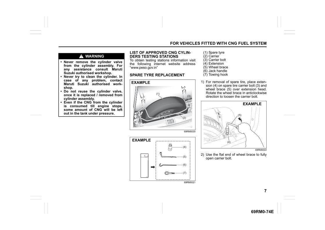
LIST OF APPROVED CNG CYLIN-DERS TESTING STATIONSTo obtain testing stations information visitthe following internet website address“www.peso.gov.in”
1) For removal of spare tire, place exten-sion (4) on spare tire carrier bolt (3) andwheel brace (5) over extension head.Rotate the wheel brace in anticlockwisedirection to loosen the carrier bolt.
69RM0022
2) Use the flat end of wheel brace to fullyopen carrier bolt.
WARNING
• Never remove the cylinder valvefrom the cylinder assembly. Forany assistance consult MarutiSuzuki authorised workshop.
• Never try to clean the cylinder. Incase of any problem, contactMaruti Suzuki authorised work-shop.
• Do not reuse the cylinder valve,once it is replaced / removed fromcylinder assembly.
• Even if the CNG from the cylinderis consumed till engine stops,some amount of CNG will be leftout in the tank under pressure.
(1)
(2)
(3)
EXAMPLE
(6)
(5)
(7)
(4)
EXAMPLE (4)
(5)
EXAMPLE
8
FOR VEHICLES FITTED WITH CNG FUEL SYSTEM
69RM0-74E
69RM0023
3) Remove extension and carrier bolt.Open the carrier and take out the sparetire.
4) For installing spare tire, follow thereverse order of removal.
NOTE:Ensure that air filling nozzle (8) is facingtowards rear of the vehicle while placingthe tire inside the carrier.
69RM0024
5) Verify that the spare tire is storedsecurely. The bolt should be tightenedtill the bracket of the carrier (2) touchesthe spacer (9).
53MHMC012
KIT IDENTIFICATION
69RM0015
CNG cylinder identification number andCNG kit installation date is mentioned onthe CNG cylinder identification platelocated inside fuel filler lid.
53MHMC017
(5)
(4)
EXAMPLE
(8)
EXAMPLE
(2)
(9)
EXAMPLE
EXAMPLE
9
FOR VEHICLES FITTED WITH CNG FUEL SYSTEM
69RM0-74E
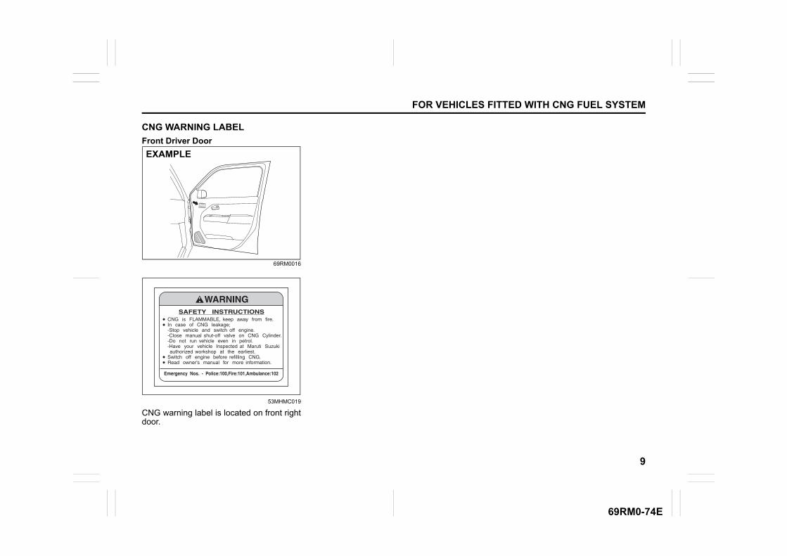
CNG WARNING LABEL
Front Driver Door
69RM0016
53MHMC019
CNG warning label is located on front rightdoor.
EXAMPLE
10
FOR VEHICLES FITTED WITH CNG FUEL SYSTEM
69RM0-74E
INSTRUMENT CLUSTER
69RM0005
(1)
(6)
(3)
(7) (4) (2) (5)
(7)
(8)
EXAMPLE
CNG MALFUNCTION WARNING LAMP
53MHMC015
When the ignition switch is turned "ON",this CNG malfunction warning lamp comeson briefly, to check that the CNG malfunc-tion lamp is trouble free.• If CNG malfunction warning lamp glows
continuously, with ignition "ON" there issome problem with the CNG system.Immediately get your vehicle checked byMaruti Suzuki authorised workshop.
• If CNG malfunction warning lamp blinksduring engine running, it means there issome problem in CNG system in whichvehicle cannot continue running in CNG-MODE and automatically switches overto petrol mode. Have your vehiclechecked at a Maruti Suzuki authorisedworkshop.
NOTE:With ignition switch "ON" and engine notrunning, blinking of CNG lamp indicatesthat fuel lid is open. Vehicle will not start inthis condition. Close the lid in order to startthe vehicle.
(5) Fuel indicator (CNG)(6) CNG malfunction warning Indicator lamp(7) Other warning and indicator lamps(8) CNG low fuel warning light
11
FOR VEHICLES FITTED WITH CNG FUEL SYSTEM
69RM0-74E
CNG LOW FUEL WARNING LIGHT
69RM0028
If this light comes on, fill the CNG tankimmediately. When this light comes on, a ding soundsonce to remind you to fill the fuel. If you do not fill the fuel, a ding soundsevery time when the ignition switch isturned to “ON” position.
FUSES
Fuses in engine compartment
69RH194
For other fuses, refer “Inspection andmaintenance” section in the main owner'smanual.
Fuses under dashboard
69RM0006
(7) 7.5A CNG valve
(25) 7.5A CNG
(43) 7.5A Spare
(6)(15)
(39) (38) (37)
(16)
(17)
(18)
(19)(20)(21)
(22)
(24)(23)
(40)(41)
(42)(25)
(28)
(26)
(27)
(29)(30)
(31)
(32)(33)(34)(35)
(7)(8)(9)
(10)
(11)
(12)
(13)
(14)
FRONT
(36)
(43)
(1) – Blank
(2) 30A Power window
(3) – Blank
(4) 20A Door lock
(5) 15A Horn
(6) 5A ABS
(7) 10A Air bag
(8) 10A Ignition 1 signal
(9) 5A Starting signal
(10) 15A Radio
(11) 5A Dome
(12) 10A Dome 2
(13) 10A Stop light
(1)
(2)
(3)
(4)
(5)
(6)
(7)
(8)(9)
(10)
(11)
(12)(13)
(14)(15)
(16)
(17)
(18)(19)
(20)
(21)
(22)
(23)
(24)(25)
(26)
(27)
(28)(29)
12
FOR VEHICLES FITTED WITH CNG FUEL SYSTEM
69RM0-74E
(14) 10A Hazard
(15) 10A Tail light
(16) 5A CNG ignition 1
(17) 25A Front wiper
(18) 15A Washer
(19) 5A Ignition 2 signal
(20) 10A Meter
(21) 15A Ignition coil
(22) 10A Backup light
(23) – Blank
(24) – Blank
(25) – Blank
(26) – Blank
(27) – Blank
(28) 5A ACC
(29) 15A ACC 2
13
FOR VEHICLES FITTED WITH CNG FUEL SYSTEM
69RM0-74E
PERIODIC MAINTENANCE SCHEDULE
Kms (1 x 1000)Month
11
56
1012
2024
3036
4048
5060
6072
7084
8096
90108
100120
Valve clearance - - - I - I - I - I - I
All Joints (Gas leakage) I I I I I I I I I I I I
Coolant Hoses(Leakage, Damage) I I I I I I I I I I I I
All Fasteners Torque values T T T T T T T T T T T T
CNG low pressure filtercartridge with O-Ring - - - R - R - R - R - R
CNG cylinder leak testing andcertification Every 3 years from the date of initial testing by govt. approved testing agency
CNG filler receptacle O-Ring Replace every 4 years or 300,000 Km, whichever comes earlier
T ........Tighten to Specified Torque I ........ Inspect and correct or replace if necessaryR ....... Replace
NOTE:• This table includes services as scheduled up to 100,000 km mileage. Beyond 100,000 km, carry out the same services at the same
intervals respectively.• For other maintenance details refer “Inspection & Maintenance” section in main Owner’s Manual.
14
FOR VEHICLES FITTED WITH CNG FUEL SYSTEM
69RM0-74E
SPECIFICATIONSMass (Weight) (Kg)
Kerb Weight 905-910 Kg
Gross Weight 1340 Kg
Seating Capacity 5 persons
Fuel Capacity (litre)
Petrol 32 L
CNG (Water Filling Capacity) 60 L
NOTE:Specifications are subject to change without notice.
NOTE:1) It is recommended to run the vehicle on petrol mode for 5~10 km after every 300~500 km run in CNG mode to keep fuel system in
good condition.2) Always keep minimum 5 litre of petrol in your petrol tank.
15
FOR VEHICLES FITTED WITH CNG FUEL SYSTEM
69RM0-74E
FIRE EXTINGUISHER (if equipped)
Do's and Don'ts
53MHMC021
Do's• Check pressure gauge periodically. Max
charging pressure is 15Kgf/cm2 (ingreen zone (2)).
• When pressure drops, indicator nee-dle(1) will shift to the red zone (3).Imme-diately contact the fire extinguishermanufacturer as per the information pro-vided on the fire extinguisher.
• Get the fire extinguisher serviced onlythrough the manufacturer service cen-tre.Refer the information provided on thefire extinguisher to locate the nearestservice centre.
• Ensure that the Fire extinguisher isalways kept at its prescribed position inthe vehicle.
• Refill the fire extinguisher immediatelyafter use.
Don't• Do not use water for cleaning fire extin-
guisher. (Use clean cloth for removingdust)
• Do not rely on used or discharged fireextinguisher.
Location
69RM0007
Fire extinguisher is located below co pas-senger's seat.
Parts Description
53MHMC024
(1) Fire extinguisher cylinder(2) Seal(3) Safety Pin(4) Lever(5) Nozzle
Removal Procedure
69RM0008
Lift Lever (1) of fire extinguisher slightlyupwards and pull the fire extinguisher inthe direction as shown in the figure, inorder to disengage it from clamps (2).
(3)(3)
(2)
(1)
EXAMPLE
EXAMPLE
(1)(5)
(2)(4)
(3)
EXAMPLE
(2)
(1)
(2)
EXAMPLE
16
FOR VEHICLES FITTED WITH CNG FUEL SYSTEM
69RM0-74E
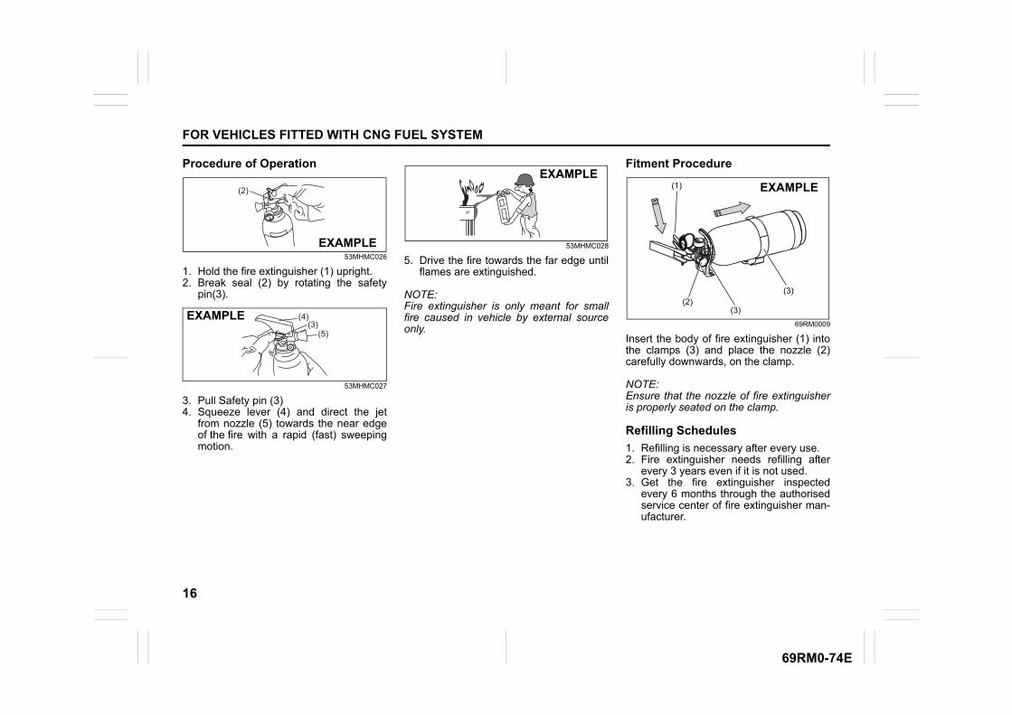
Procedure of Operation
53MHMC026
1. Hold the fire extinguisher (1) upright.2. Break seal (2) by rotating the safety
pin(3).
53MHMC027
3. Pull Safety pin (3)4. Squeeze lever (4) and direct the jet
from nozzle (5) towards the near edgeof the fire with a rapid (fast) sweepingmotion.
53MHMC028
5. Drive the fire towards the far edge untilflames are extinguished.
NOTE:Fire extinguisher is only meant for smallfire caused in vehicle by external sourceonly.
Fitment Procedure
69RM0009
Insert the body of fire extinguisher (1) intothe clamps (3) and place the nozzle (2)carefully downwards, on the clamp.
NOTE:Ensure that the nozzle of fire extinguisheris properly seated on the clamp.
Refilling Schedules
1. Refilling is necessary after every use.2. Fire extinguisher needs refilling after
every 3 years even if it is not used.3. Get the fire extinguisher inspected
every 6 months through the authorisedservice center of fire extinguisher man-ufacturer.