Page 1
FORM-1
for
PROPOSED BULK DRUGS AND BULK DRUG INTERMEDIATES
MANUFACTURING UNIT
of
M/s. SIGMA LIFE SCIENCE
Plot No. 1032/16, Phase II,
GIDC Industrial Estate, Panoli, Tal: Ankleshwar,
Dist: Bharuch-394116 (Guj.)
Prepared by:
Aqua-Air Environmental Engineers Pvt. Ltd.
(Pollution Control Consultants & Engineers)
Reg. Office: 403, Centre Point, Nr. Kadiwala School, Ring Road,
Surat – 395 002, Gujarat, India Fax: +91 261 2707273 / 3987273
Tel: + 91 261 3048586 / 2460854 / 2461241 E-mail: [email protected] Visit us at: www.aqua-air.co.in
Page 2
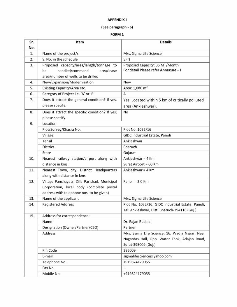
APPENDIX I
(See paragraph - 6)
FORM 1
Sr.
No.
Item Details
1. Name of the project/s M/s. Sigma Life Science 2. S. No. in the schedule 5 (f)
3. Proposed capacity/area/length/tonnage to
be handled/command area/lease
area/number of wells to be drilled
Proposed Capacity: 35 MT/Month
For detail Please refer Annexure – I
4. New/Expansion/Modernization New
5. Existing Capacity/Area etc. Area: 1,080 m2
6. Category of Project i.e. ‘A’ or ‘B’ A
7. Does it attract the general condition? If yes,
please specify.
Yes. Located within 5 km of critically polluted
area (Ankleshwar).
8. Does it attract the specific condition? If yes,
please specify.
No
9. Location
Plot/Survey/Khasra No. Plot No. 1032/16
Village GIDC Industrial Estate, Panoli
Tehsil Ankleshwar
District Bharuch
State Gujarat
10. Nearest railway station/airport along with
distance in kms.
Ankleshwar = 4 Km
Surat Airport = 60 Km
11. Nearest Town, city, District Headquarters
along with distance in kms.
Ankleshwar = 4 Km
12. Village Panchayats, Zilla Parishad, Municipal
Corporation, local body (complete postal
address with telephone nos. to be given)
Panoli = 2.0 Km
13. Name of the applicant M/s. Sigma Life Science
14. Registered Address Plot No. 1032/16, GIDC Industrial Estate, Panoli,
Tal: Ankleshwar, Dist: Bharuch-394116 (Guj.)
15. Address for correspondence:
Name Dr. Rajan Rudalal
Designation (Owner/Partner/CEO) Partner
Address M/s. Sigma Life Science, 16, Wadia Nagar, Near
Nagardas Hall, Opp. Water Tank, Adajan Road,
Surat-395009 (Guj.)
Pin Code 395009
E-mail [email protected]
Telephone No. +919824179055
Fax No. --
Mobile No. +919824179055
Page 3
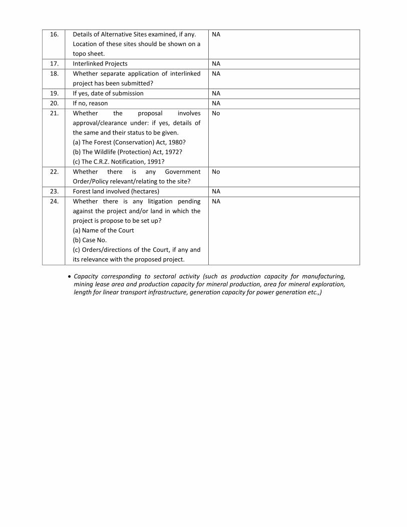
16. Details of Alternative Sites examined, if any.
Location of these sites should be shown on a
topo sheet.
NA
17. Interlinked Projects NA
18. Whether separate application of interlinked
project has been submitted?
NA
19. If yes, date of submission NA
20. If no, reason NA
21. Whether the proposal involves
approval/clearance under: if yes, details of
the same and their status to be given.
(a) The Forest (Conservation) Act, 1980?
(b) The Wildlife (Protection) Act, 1972?
(c) The C.R.Z. Notification, 1991?
No
22. Whether there is any Government
Order/Policy relevant/relating to the site?
No
23. Forest land involved (hectares) NA
24. Whether there is any litigation pending
against the project and/or land in which the
project is propose to be set up?
(a) Name of the Court
(b) Case No.
(c) Orders/directions of the Court, if any and
its relevance with the proposed project.
NA
• Capacity corresponding to sectoral activity (such as production capacity for manufacturing,
mining lease area and production capacity for mineral production, area for mineral exploration,
length for linear transport infrastructure, generation capacity for power generation etc.,)
Page 4
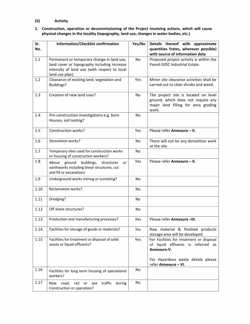
(II) Activity
1. Construction, operation or decommissioning of the Project involving actions, which will cause
physical changes in the locality (topography, land use, changes in water bodies, etc.)
Sr.
No.
Information/Checklist confirmation Yes/No Details thereof with approximate
quantities frates, wherever possible)
with source of information data
1.1 Permanent or temporary change in land use,
land cover or topography including increase
intensity of land use (with respect to local
land use plan)
No Proposed project activity is within the
Panoli GIDC Industrial Estate.
1.2 Clearance of existing land, vegetation and
Buildings?
Yes Minor site clearance activities shall be
carried out to clear shrubs and weed.
1.3 Creation of new land uses?
No The project site is located on level
ground, which does not require any
major land filling for area grading
work.
1.4 Pre-construction investigations e.g. bore
Houses, soil testing?
No
1.5 Construction works?
Yes Please refer Annexure – II.
1.6 Demolition works? No There will not be any demolition work
at the site.
1.7 Temporary sites used for construction works
or housing of construction workers?
No
1.8 Above ground buildings, structures or
earthworks including linear structures, cut
and fill or excavations
Yes Please refer Annexure – II.
1.9 Underground works mining or tunneling?
No
1.10 Reclamation works?
No
1.11 Dredging?
No
1.12 Off shore structures?
No
1.13 Production and manufacturing processes?
Yes Please refer Annexure –III.
1.14 Facilities for storage of goods or materials?
Yes Raw material & finished products
storage area will be developed.
1.15 Facilities for treatment or disposal of solid
waste or liquid effluents?
Yes For Facilities for treatment or disposal
of liquid effluents is referred as
Annexure-V.
For Hazardous waste details please
refer Annexure – VI.
1.16 Facilities for long term housing of operational
workers?
No
1.17 New road, rail or sea traffic during
Construction or operation?
No
Page 5
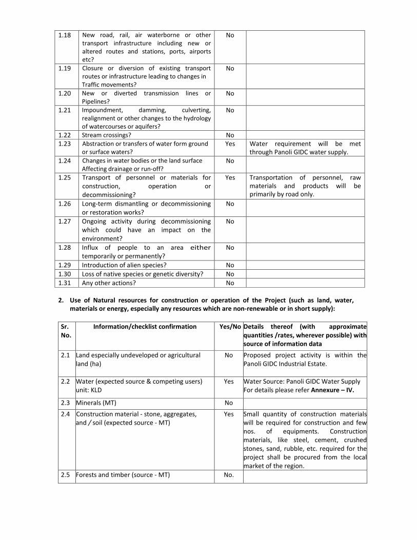
1.18 New road, rail, air waterborne or other
transport infrastructure including new or
altered routes and stations, ports, airports
etc?
No
1.19 Closure or diversion of existing transport
routes or infrastructure leading to changes in
Traffic movements?
No
1.20 New or diverted transmission lines or
Pipelines?
No
1.21 Impoundment, damming, culverting,
realignment or other changes to the hydrology
of watercourses or aquifers?
No
1.22 Stream crossings? No
1.23 Abstraction or transfers of water form ground
or surface waters?
Yes Water requirement will be met
through Panoli GIDC water supply.
1.24 Changes in water bodies or the land surface
Affecting drainage or run-off?
No
1.25 Transport of personnel or materials for
construction, operation or
decommissioning?
Yes Transportation of personnel, raw
materials and products will be
primarily by road only.
1.26 Long-term dismantling or decommissioning
or restoration works?
No
1.27 Ongoing activity during decommissioning
which could have an impact on the
environment?
No
1.28 Influx of people to an area either
temporarily or permanently?
No
1.29 Introduction of alien species? No
1.30 Loss of native species or genetic diversity? No
1.31 Any other actions? No
2. Use of Natural resources for construction or operation of the Project (such as land, water,
materials or energy, especially any resources which are non-renewable or in short supply):
Sr.
No.
Information/checklist confirmation Yes/No Details thereof (with approximate
quantities /rates, wherever possible) with
source of information data
2.1 Land especially undeveloped or agricultural
land (ha)
No Proposed project activity is within the
Panoli GIDC Industrial Estate.
2.2 Water (expected source & competing users)
unit: KLD
Yes Water Source: Panoli GIDC Water Supply
For details please refer Annexure – IV.
2.3 Minerals (MT) No
2.4 Construction material - stone, aggregates,
and / soil (expected source - MT)
Yes Small quantity of construction materials
will be required for construction and few
nos. of equipments. Construction
materials, like steel, cement, crushed
stones, sand, rubble, etc. required for the
project shall be procured from the local
market of the region.
2.5 Forests and timber (source - MT) No.
Page 6
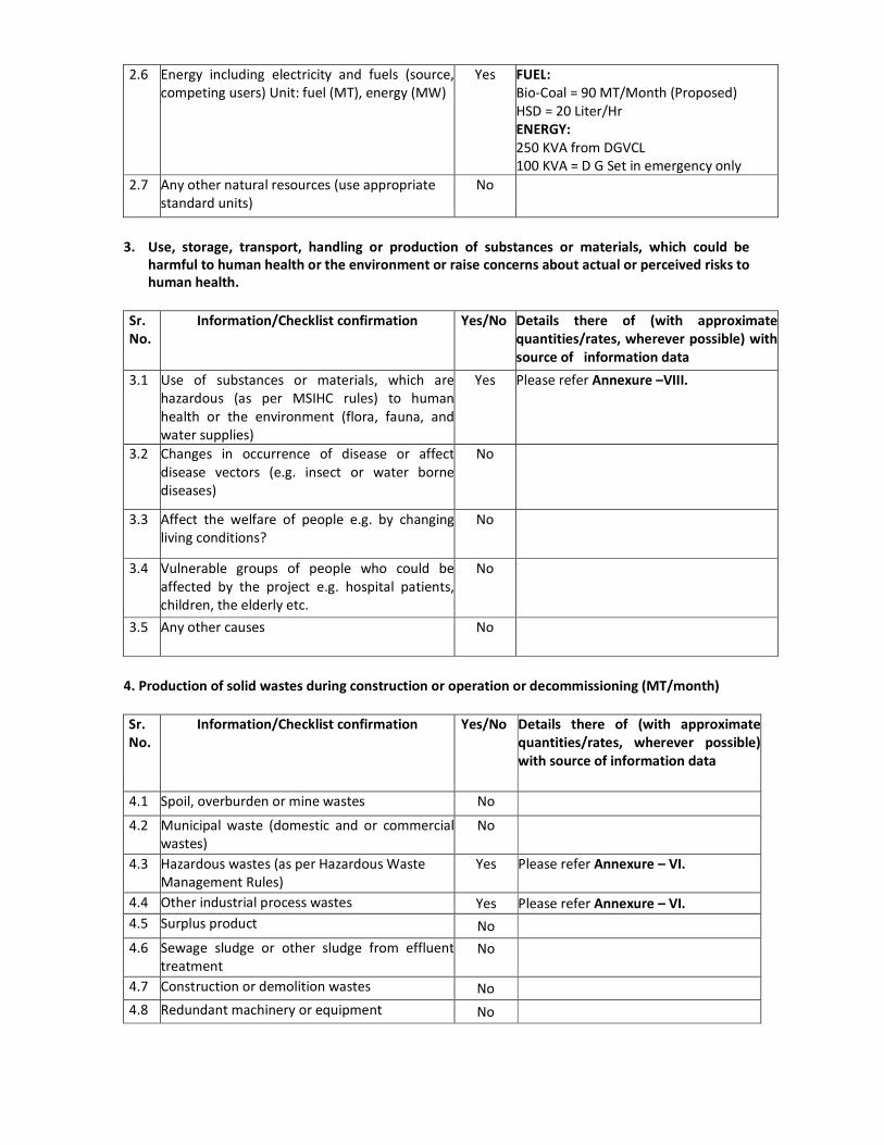
2.6 Energy including electricity and fuels (source,
competing users) Unit: fuel (MT), energy (MW)
Yes FUEL:
Bio-Coal = 90 MT/Month (Proposed)
HSD = 20 Liter/Hr
ENERGY:
250 KVA from DGVCL
100 KVA = D G Set in emergency only
2.7 Any other natural resources (use appropriate
standard units)
No
3. Use, storage, transport, handling or production of substances or materials, which could be
harmful to human health or the environment or raise concerns about actual or perceived risks to
human health.
Sr.
No.
Information/Checklist confirmation Yes/No Details there of (with approximate
quantities/rates, wherever possible) with
source of information data
3.1 Use of substances or materials, which are
hazardous (as per MSIHC rules) to human
health or the environment (flora, fauna, and
water supplies)
Yes Please refer Annexure –VIII.
3.2 Changes in occurrence of disease or affect
disease vectors (e.g. insect or water borne
diseases)
No
3.3 Affect the welfare of people e.g. by changing
living conditions?
No
3.4 Vulnerable groups of people who could be
affected by the project e.g. hospital patients,
children, the elderly etc.
No
3.5 Any other causes No
4. Production of solid wastes during construction or operation or decommissioning (MT/month)
Sr.
No.
Information/Checklist confirmation Yes/No Details there of (with approximate
quantities/rates, wherever possible)
with source of information data
4.1 Spoil, overburden or mine wastes No
4.2 Municipal waste (domestic and or commercial
wastes)
No
4.3 Hazardous wastes (as per Hazardous Waste
Management Rules)
Yes Please refer Annexure – VI.
4.4 Other industrial process wastes Yes Please refer Annexure – VI.
4.5 Surplus product No
4.6 Sewage sludge or other sludge from effluent
treatment
No
4.7 Construction or demolition wastes No
4.8 Redundant machinery or equipment No
Page 7
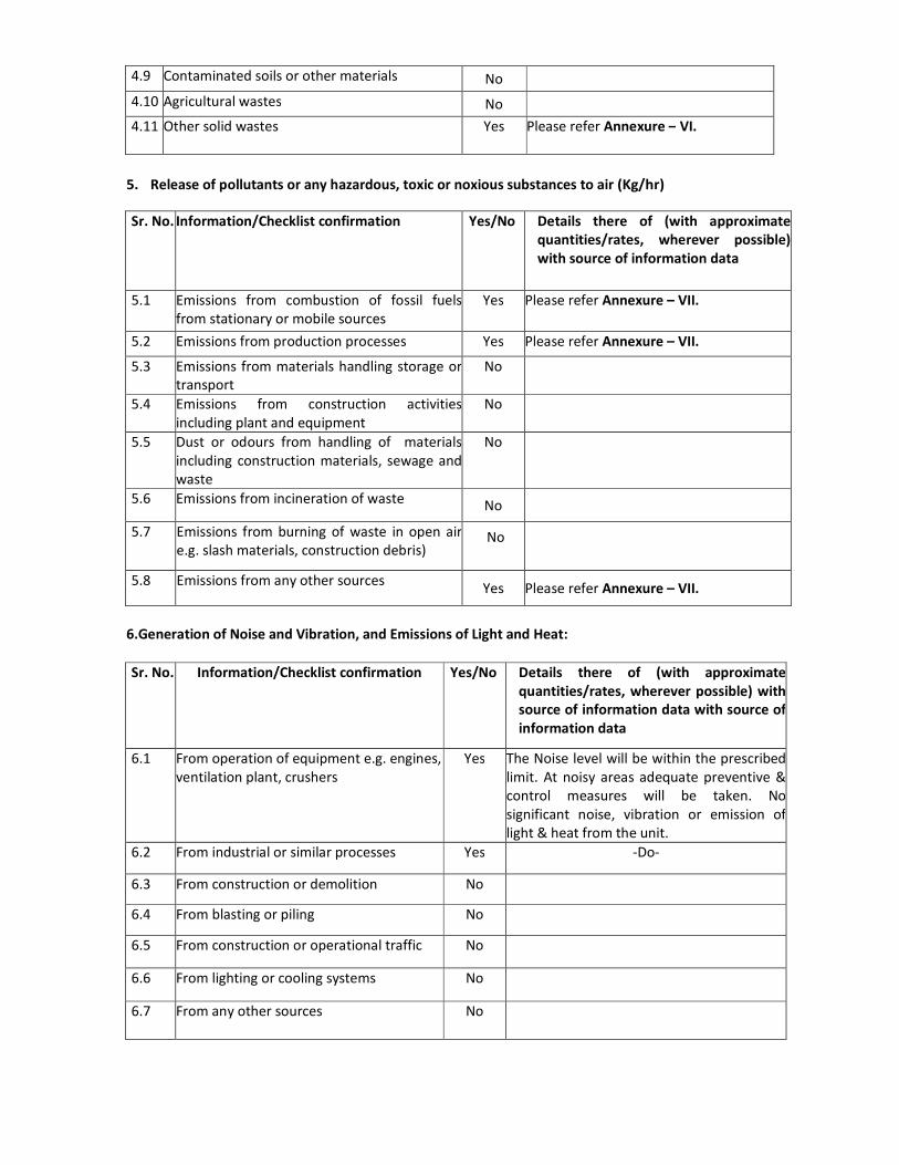
4.9 Contaminated soils or other materials No
4.10 Agricultural wastes No
4.11 Other solid wastes Yes
Please refer Annexure – VI.
5. Release of pollutants or any hazardous, toxic or noxious substances to air (Kg/hr)
Sr. No. Information/Checklist confirmation Yes/No Details there of (with approximate
quantities/rates, wherever possible)
with source of information data
5.1 Emissions from combustion of fossil fuels
from stationary or mobile sources
Yes Please refer Annexure – VII.
5.2 Emissions from production processes Yes Please refer Annexure – VII.
5.3 Emissions from materials handling storage or
transport
No
5.4 Emissions from construction activities
including plant and equipment
No
5.5 Dust or odours from handling of materials
including construction materials, sewage and
waste
No
5.6 Emissions from incineration of waste No
5.7 Emissions from burning of waste in open air
e.g. slash materials, construction debris) No
5.8 Emissions from any other sources Yes Please refer Annexure – VII.
6.Generation of Noise and Vibration, and Emissions of Light and Heat:
Sr. No. Information/Checklist confirmation Yes/No Details there of (with approximate
quantities/rates, wherever possible) with
source of information data with source of
information data
6.1 From operation of equipment e.g. engines,
ventilation plant, crushers
Yes The Noise level will be within the prescribed
limit. At noisy areas adequate preventive &
control measures will be taken. No
significant noise, vibration or emission of
light & heat from the unit.
6.2 From industrial or similar processes Yes -Do-
6.3 From construction or demolition No
6.4 From blasting or piling No
6.5 From construction or operational traffic No
6.6 From lighting or cooling systems No
6.7 From any other sources No
Page 8
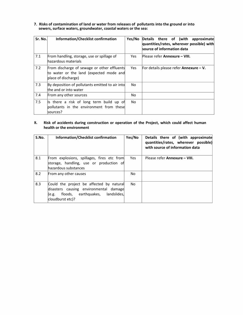
7. Risks of contamination of land or water from releases of pollutants into the ground or into sewers, surface waters, groundwater, coastal waters or the sea:
Sr. No. Information/Checklist confirmation Yes/No Details there of (with approximate
quantities/rates, wherever possible) with
source of information data
7.1 From handling, storage, use or spillage of
hazardous materials
Yes Please refer Annexure – VIII.
7.2 From discharge of sewage or other effluents
to water or the land (expected mode and
place of discharge)
Yes For details please refer Annexure – V.
7.3 By deposition of pollutants emitted to air into
the and or into water
No
7.4 From any other sources No
7.5 Is there a risk of long term build up of
pollutants in the environment from these
sources?
No
8. Risk of accidents during construction or operation of the Project, which could affect human
health or the environment
S.No. Information/Checklist confirmation Yes/No Details there of (with approximate
quantities/rates, wherever possible)
with source of information data
8.1 From explosions, spillages, fires etc from
storage, handling, use or production of
hazardous substances
Yes Please refer Annexure – VIII.
8.2 From any other causes No
8.3 Could the project be affected by natural
disasters causing environmental damage
(e.g. floods, earthquakes, landslides,
cloudburst etc)?
No
Page 9
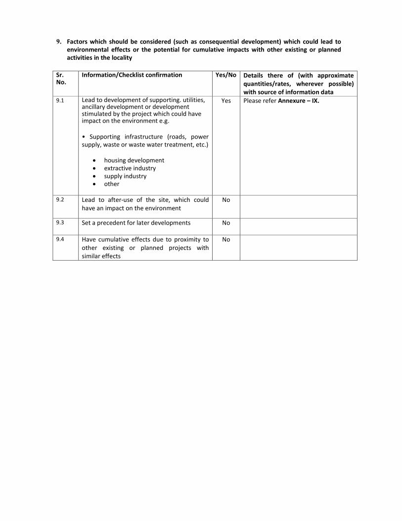
9. Factors which should be considered (such as consequential development) which could lead to
environmental effects or the potential for cumulative impacts with other existing or planned
activities in the locality
Sr. No.
Information/Checklist confirmation
Yes/No
Details there of (with approximate
quantities/rates, wherever possible)
with source of information data
9.1 Lead to development of supporting. utilities, ancillary development or development stimulated by the project which could have impact on the environment e.g.
• Supporting infrastructure (roads, power
supply, waste or waste water treatment, etc.)
• housing development
• extractive industry
• supply industry
• other
Yes Please refer Annexure – IX.
9.2 Lead to after-use of the site, which could
have an impact on the environment
No
9.3 Set a precedent for later developments No
9.4 Have cumulative effects due to proximity to
other existing or planned projects with
similar effects
No
Page 10
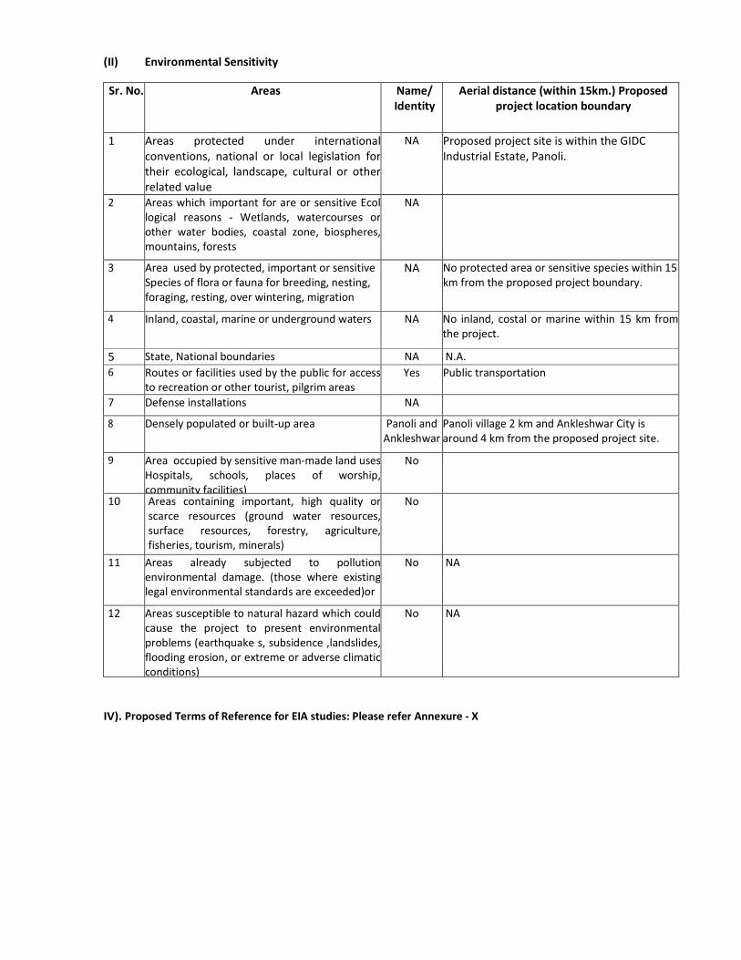
(II) Environmental Sensitivity
Sr. No. Areas Name/
Identity
Aerial distance (within 15km.) Proposed
project location boundary
1 Areas protected under international
conventions, national or local legislation for
their ecological, landscape, cultural or other
related value
NA Proposed project site is within the GIDC
Industrial Estate, Panoli.
2 Areas which important for are or sensitive Ecol
logical reasons - Wetlands, watercourses or
other water bodies, coastal zone, biospheres,
mountains, forests
NA
3 Area used by protected, important or sensitive
Species of flora or fauna for breeding, nesting,
foraging, resting, over wintering, migration
NA No protected area or sensitive species within 15
km from the proposed project boundary.
4 Inland, coastal, marine or underground waters NA No inland, costal or marine within 15 km from
the project.
5 State, National boundaries NA N.A.
6 Routes or facilities used by the public for access
to recreation or other tourist, pilgrim areas
Yes Public transportation
7 Defense installations NA
8 Densely populated or built-up area Panoli and
Ankleshwar
Panoli village 2 km and Ankleshwar City is
around 4 km from the proposed project site.
9 Area occupied by sensitive man-made land uses
Hospitals, schools, places of worship,
community facilities)
No
10 Areas containing important, high quality or
scarce resources (ground water resources,
surface resources, forestry, agriculture,
fisheries, tourism, minerals)
No
11 Areas already subjected to pollution
environmental damage. (those where existing
legal environmental standards are exceeded)or
No NA
12 Areas susceptible to natural hazard which could
cause the project to present environmental
problems (earthquake s, subsidence ,landslides,
flooding erosion, or extreme or adverse climatic
conditions)
No NA
IV). Proposed Terms of Reference for EIA studies: Please refer Annexure - X
Page 11
Date: Feb. 6, 2017
Place: Surat
Rajan Rudalal
(Partner)
Signature of applicant with full name & Address
(Project Proponent/Authorized Signatory)
Page 12
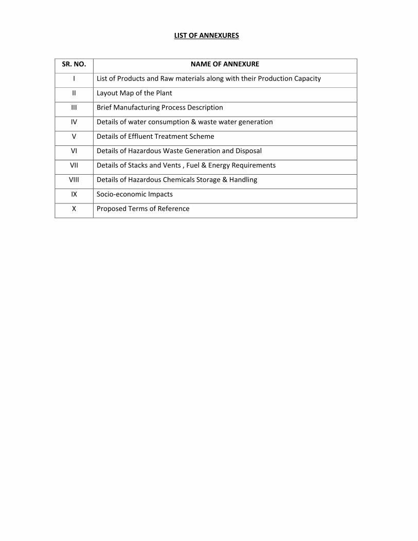
LIST OF ANNEXURES
SR. NO. NAME OF ANNEXURE
I List of Products and Raw materials along with their Production Capacity
II Layout Map of the Plant
III Brief Manufacturing Process Description
IV Details of water consumption & waste water generation
V Details of Effluent Treatment Scheme
VI Details of Hazardous Waste Generation and Disposal
VII Details of Stacks and Vents , Fuel & Energy Requirements
VIII Details of Hazardous Chemicals Storage & Handling
IX Socio-economic Impacts
X Proposed Terms of Reference
Page 13
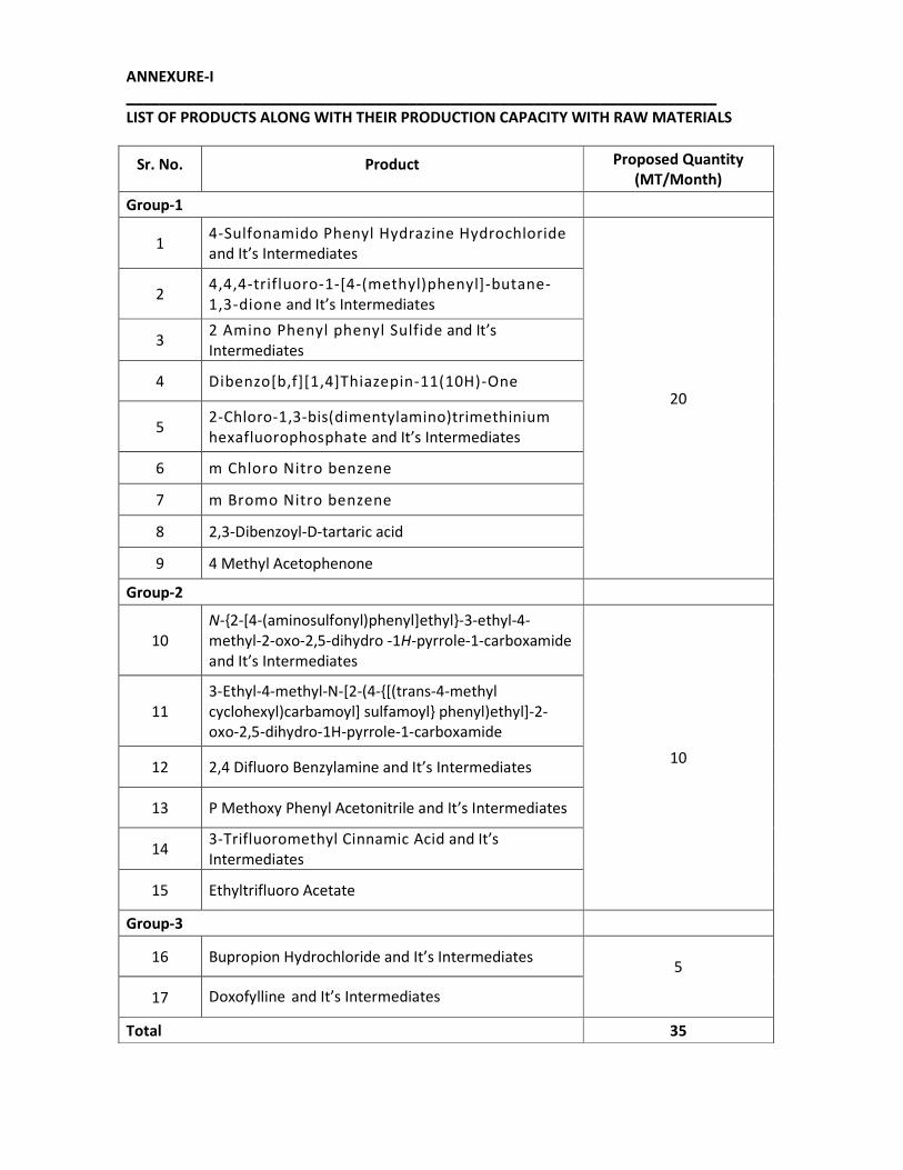
ANNEXURE-I
_______________________________________________________________________
LIST OF PRODUCTS ALONG WITH THEIR PRODUCTION CAPACITY WITH RAW MATERIALS
Sr. No. Product Proposed Quantity
(MT/Month)
Group-1
1 4-Sulfonamido Phenyl Hydrazine Hydrochloride
and It’s Intermediates
20
2 4,4,4-trifluoro-1-[4-(methyl)phenyl]-butane-
1,3-dione and It’s Intermediates
3 2 Amino Phenyl phenyl Sulfide and It’s
Intermediates
4 Dibenzo[b,f][1,4]Thiazepin-11(10H)-One
5 2-Chloro-1,3-bis(dimentylamino)trimethinium
hexafluorophosphate and It’s Intermediates
6 m Chloro Nitro benzene
7 m Bromo Nitro benzene
8 2,3-Dibenzoyl-D-tartaric acid
9 4 Methyl Acetophenone
Group-2
10
N-{2-[4-(aminosulfonyl)phenyl]ethyl}-3-ethyl-4-
methyl-2-oxo-2,5-dihydro -1H-pyrrole-1-carboxamide
and It’s Intermediates
10
11
3-Ethyl-4-methyl-N-[2-(4-{[(trans-4-methyl
cyclohexyl)carbamoyl] sulfamoyl} phenyl)ethyl]-2-
oxo-2,5-dihydro-1H-pyrrole-1-carboxamide
12 2,4 Difluoro Benzylamine and It’s Intermediates
13 P Methoxy Phenyl Acetonitrile and It’s Intermediates
14 3-Trifluoromethyl Cinnamic Acid and It’s
Intermediates
15 Ethyltrifluoro Acetate
Group-3
16 Bupropion Hydrochloride and It’s Intermediates 5
17 Doxofylline and It’s Intermediates
Total 35
Page 14
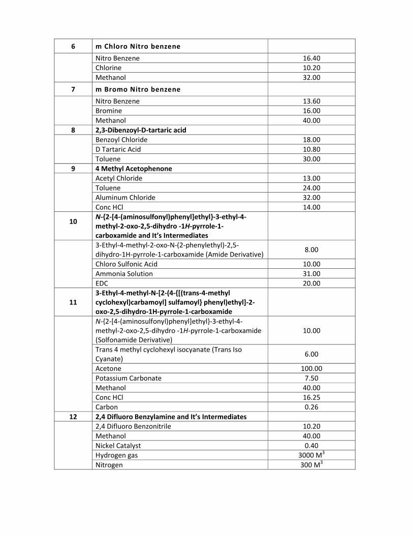
RAW MATERIAL CONSUMPTION
Sr. No. Raw Material Quantity (MT/Month)
1 4-Sulfonamido Phenyl Hydrazine Hydrochloride
and It’s Intermediates
Sulfanilamide 16.20
Sodium Nitrite 7.00
Sodium bisulphite 10.60
Conc HCl 34.00
2 4,4,4-trifluoro-1-[4-(methyl)phenyl]-butane-
1,3-dione and It’s Intermediates
Sodium Methoxide 5.60
Toluene 30.00
4-Methylacetophenone 12.00
Methyltrifluoroacetate 12.40
Conc HCl 11.60
3 2 Amino Phenyl phenyl Sulfide and It’s
Intermediates
Thio Phenol 12.80
2 Nitro Chloro Benzene 17.20
Caustic Flakes 5.60
Raney Nickel 0.40
Methanol 80.00
Hydrogen gas 16000 M3
Nitrogen 1600 M3
4 Dibenzo[b,f][1,4]Thiazepin-11(10H)-One
2 Amino phenyl phenyl sulfide 19.00
Poly Phosphoric Acid 60.00
Ethyl Chloro formate 12.50
Toluene 60.00
Carbon 1.00
5 2-Chloro-1,3-bis(dimentylamino)trimethinium
hexafluorophosphate and It’s Intermediates
Poly Phosphoric Acid 8.30
HF Gas 11.70
Dimethylformamide 7.20
Chloroacetyl chloride 8.00
Phosphorus Oxychloride 11.00
Caustic Flakes 13.20
Hexafluorophosphoric acid 18.00
Page 15
6 m Chloro Nitro benzene
Nitro Benzene 16.40
Chlorine 10.20
Methanol 32.00
7 m Bromo Nitro benzene
Nitro Benzene 13.60
Bromine 16.00
Methanol 40.00
8 2,3-Dibenzoyl-D-tartaric acid
Benzoyl Chloride 18.00
D Tartaric Acid 10.80
Toluene 30.00
9 4 Methyl Acetophenone
Acetyl Chloride 13.00
Toluene 24.00
Aluminum Chloride 32.00
Conc HCl 14.00
10
N-{2-[4-(aminosulfonyl)phenyl]ethyl}-3-ethyl-4-
methyl-2-oxo-2,5-dihydro -1H-pyrrole-1-
carboxamide and It’s Intermediates
3-Ethyl-4-methyl-2-oxo-N-(2-phenylethyl)-2,5-
dihydro-1H-pyrrole-1-carboxamide (Amide Derivative) 8.00
Chloro Sulfonic Acid 10.00
Ammonia Solution 31.00
EDC 20.00
11
3-Ethyl-4-methyl-N-[2-(4-{[(trans-4-methyl
cyclohexyl)carbamoyl] sulfamoyl} phenyl)ethyl]-2-
oxo-2,5-dihydro-1H-pyrrole-1-carboxamide
N-{2-[4-(aminosulfonyl)phenyl]ethyl}-3-ethyl-4-
methyl-2-oxo-2,5-dihydro -1H-pyrrole-1-carboxamide
(Solfonamide Derivative)
10.00
Trans 4 methyl cyclohexyl isocyanate (Trans Iso
Cyanate) 6.00
Acetone 100.00
Potassium Carbonate 7.50
Methanol 40.00
Conc HCl 16.25
Carbon 0.26
12 2,4 Difluoro Benzylamine and It’s Intermediates
2,4 Difluoro Benzonitrile 10.20
Methanol 40.00
Nickel Catalyst 0.40
Hydrogen gas 3000 M3
Nitrogen 300 M3
Page 16
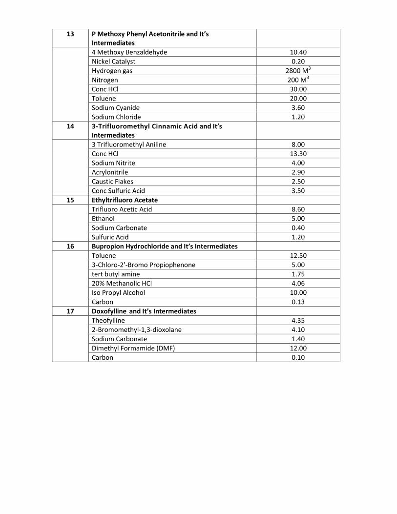
13 P Methoxy Phenyl Acetonitrile and It’s
Intermediates
4 Methoxy Benzaldehyde 10.40
Nickel Catalyst 0.20
Hydrogen gas 2800 M3
Nitrogen 200 M3
Conc HCl 30.00
Toluene 20.00
Sodium Cyanide 3.60
Sodium Chloride 1.20
14 3-Trifluoromethyl Cinnamic Acid and It’s
Intermediates
3 Trifluoromethyl Aniline 8.00
Conc HCl 13.30
Sodium Nitrite 4.00
Acrylonitrile 2.90
Caustic Flakes 2.50
Conc Sulfuric Acid 3.50
15 Ethyltrifluoro Acetate
Trifluoro Acetic Acid 8.60
Ethanol 5.00
Sodium Carbonate 0.40
Sulfuric Acid 1.20
16 Bupropion Hydrochloride and It’s Intermediates
Toluene 12.50
3-Chloro-2’-Bromo Propiophenone 5.00
tert butyl amine 1.75
20% Methanolic HCl 4.06
Iso Propyl Alcohol 10.00
Carbon 0.13
17 Doxofylline and It’s Intermediates
Theofylline 4.35
2-Bromomethyl-1,3-dioxolane 4.10
Sodium Carbonate 1.40
Dimethyl Formamide (DMF) 12.00
Carbon 0.10
Page 17
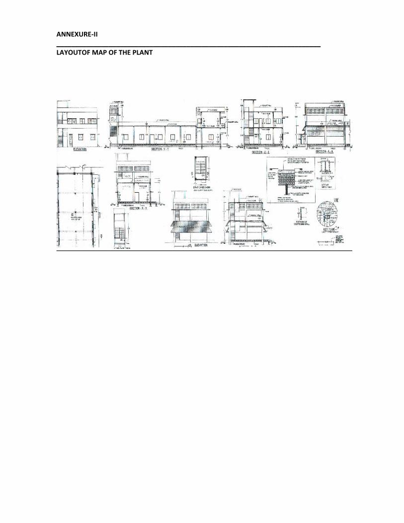
ANNEXURE-II
_______________________________________________________________________
LAYOUTOF MAP OF THE PLANT
Page 18
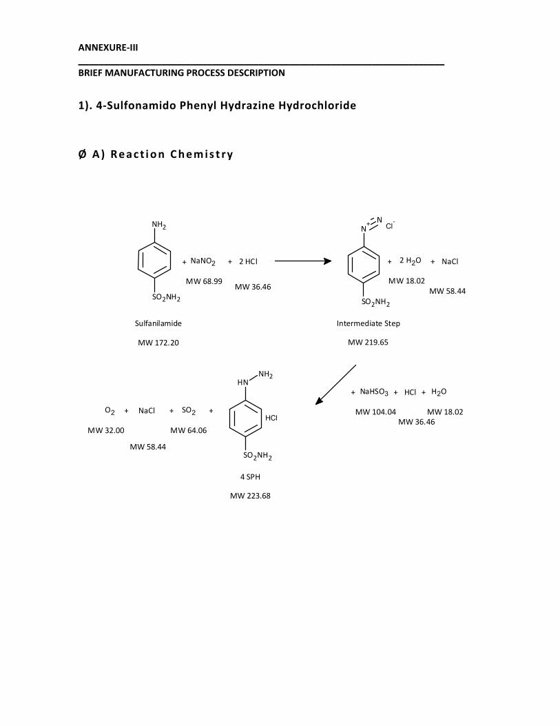
ANNEXURE-III
_______________________________________________________________________
BRIEF MANUFACTURING PROCESS DESCRIPTION
1). 4-Sulfonamido Phenyl Hydrazine Hydrochloride
Ø A ) R e a c t i o n C h e m i s t ry
MW 219.65
Intermediate Step
SO2NH2
NH2
MW 172.20
Sulfanilamide
NaNO2+ + 2 HCl
MW 68.99MW 36.46
2 H2O+ + NaCl
MW 18.02
MW 58.44
SO2NH2
N+
NCl
-
MW 223.68
4 SPH
SO2+
MW 64.06
SO2NH2
NHNH2
ClH
NaHSO3+ + HCl
MW 104.04
MW 36.46
H2O
MW 18.02
+
NaCl
MW 58.44
O2 +
MW 32.00
+
Page 19
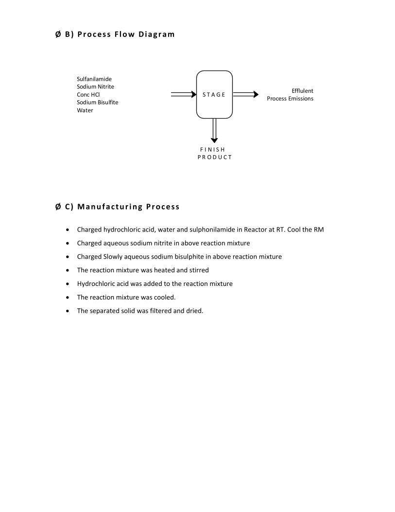
Ø B ) P r o c es s F l o w D i a g r am
Sulfanilamide
Sodium Nitrite
Conc HCl
Sodium Bisulfite
Water
S T A G E Efflulent
Process Emissions
F I N I S H
P R O D U C T
Ø C ) M a n u f a c t u r i n g P r o c e s s
• Charged hydrochloric acid, water and sulphonilamide in Reactor at RT. Cool the RM
• Charged aqueous sodium nitrite in above reaction mixture
• Charged Slowly aqueous sodium bisulphite in above reaction mixture
• The reaction mixture was heated and stirred
• Hydrochloric acid was added to the reaction mixture
• The reaction mixture was cooled.
• The separated solid was filtered and dried.
Page 20
Ø D ) S u m m a ry o f M a s s
Capacity, Mt/Month : 20.00
Batch Size, Kg : 400
Working Days : 26
Sr.
No Name of Raw Material Kg/batch
Kg/Kg of
Product MT/Month Remarks
Input
1 Sulfanilamide 325 0.81 16.20
2 Sodium Nitrite 140 0.35 7.00
3 Sodium bisulphite 210 0.53 10.60
4 Conc HCl 680 1.70 34.00
5 Water 400 1.00 20.00
Total 1755
Output
1 Final Product 400 1.00 20.00 Finished product
2 Drying Loss 185 0.46 9.20
3 Effluent 1170 2.93 58.60
Total 1755
Page 21
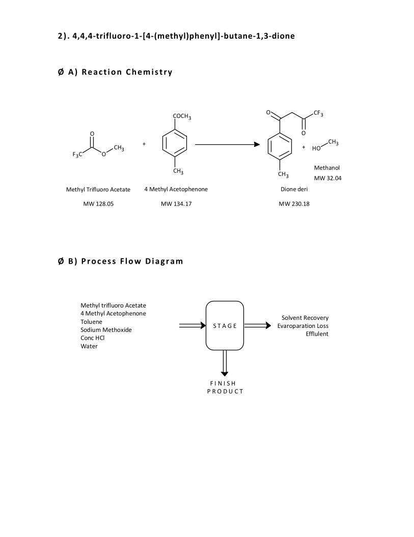
2 ) . 4,4,4-trifluoro-1-[4-(methyl)phenyl]-butane-1,3-dione
Ø A ) R e a c t i o n C h e m i s t ry
CH3
O CF3
O
MW 230.18
Dione deri
COCH3
CH3
MW 134.17
4 Methyl Acetophenone
F3C O
O
CH3
MW 128.05
Methyl Trifluoro Acetate
++ OH
CH3
MW 32.04
Methanol
Ø B ) P r o c es s F l o w D i a g r am
Methyl trifluoro Acetate
4 Methyl Acetophenone
Toluene
Sodium Methoxide
Conc HCl
Water
S T A G E
Solvent Recovery
Evaroparation Loss
Efflulent
F I N I S H
P R O D U C T
Page 22
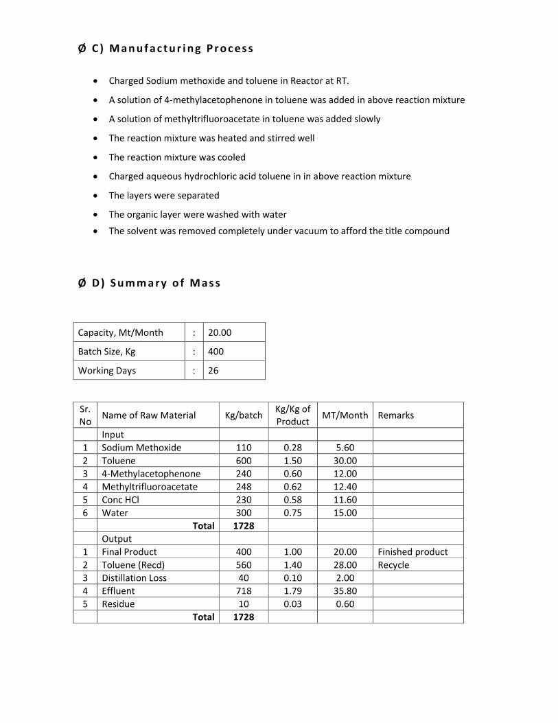
Ø C ) M a n u f a c t u r i n g P r o c e s s
• Charged Sodium methoxide and toluene in Reactor at RT.
• A solution of 4-methylacetophenone in toluene was added in above reaction mixture
• A solution of methyltrifluoroacetate in toluene was added slowly
• The reaction mixture was heated and stirred well
• The reaction mixture was cooled
• Charged aqueous hydrochloric acid toluene in in above reaction mixture
• The layers were separated
• The organic layer were washed with water
• The solvent was removed completely under vacuum to afford the title compound
Ø D ) S u m m a ry o f M a s s
Capacity, Mt/Month : 20.00
Batch Size, Kg : 400
Working Days : 26
Sr.
No Name of Raw Material Kg/batch
Kg/Kg of
Product MT/Month Remarks
Input
1 Sodium Methoxide 110 0.28 5.60
2 Toluene 600 1.50 30.00
3 4-Methylacetophenone 240 0.60 12.00
4 Methyltrifluoroacetate 248 0.62 12.40
5 Conc HCl 230 0.58 11.60
6 Water 300 0.75 15.00
Total 1728
Output
1 Final Product 400 1.00 20.00 Finished product
2 Toluene (Recd) 560 1.40 28.00 Recycle
3 Distillation Loss 40 0.10 2.00
4 Effluent 718 1.79 35.80
5 Residue 10 0.03 0.60
Total 1728
Page 23
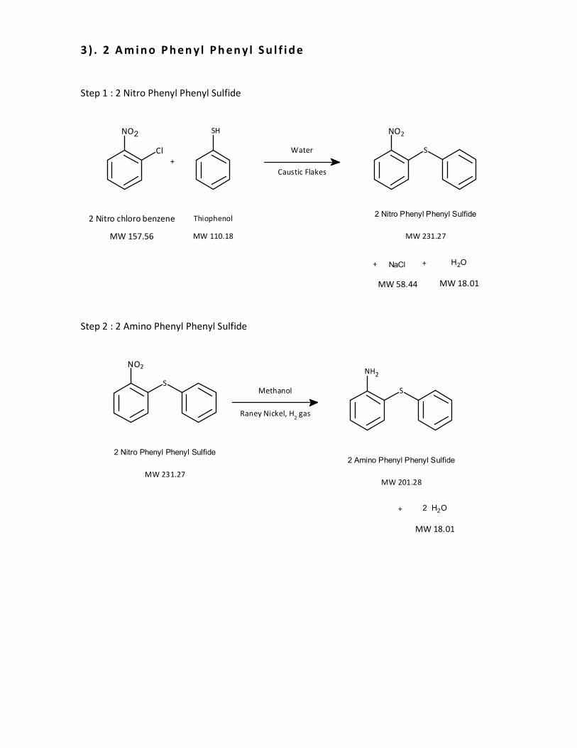
3 ) . 2 A m i n o P h en y l P h en y l S u l f i d e
Step 1 : 2 Nitro Phenyl Phenyl Sulfide
MW 231.27
2 Nitro Phenyl Phenyl Sulfide
Water
Caustic Flakes
MW 110.18
Thiophenol
SHNO2
Cl
MW 157.56
2 Nitro chloro benzene
+
+ NaCl + H2O
MW 58.44 MW 18.01
NO2
S
Step 2 : 2 Amino Phenyl Phenyl Sulfide
MW 201.28
2 Amino Phenyl Phenyl Sulfide
Methanol
Raney Nickel, H2 gas
+ 2 H2O
MW 18.01
NH2
S
MW 231.27
2 Nitro Phenyl Phenyl Sulfide
NO2
S
Page 24
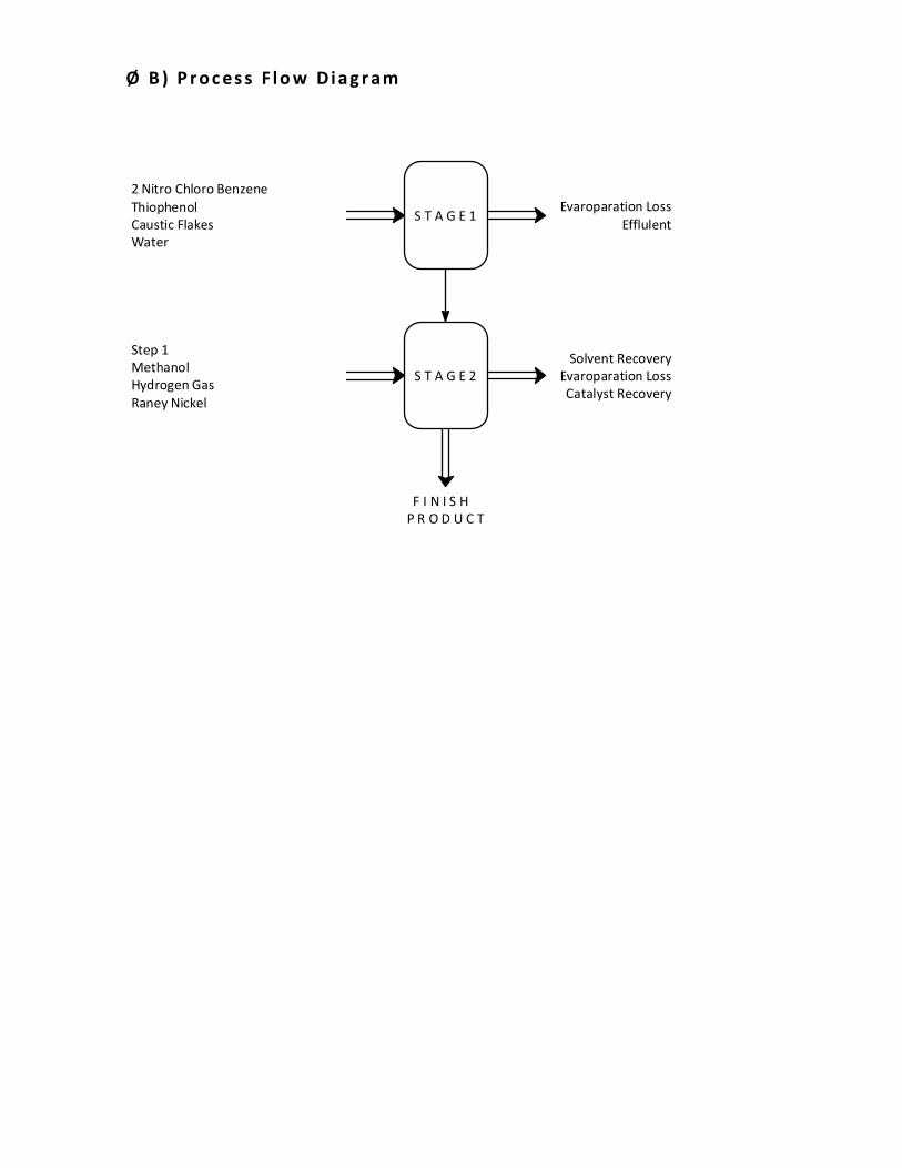
Ø B ) P r o c es s F l o w D i a g r am
2 Nitro Chloro Benzene
Thiophenol
Caustic Flakes
Water
S T A G E 1Evaroparation Loss
Efflulent
Step 1
Methanol
Hydrogen Gas
Raney Nickel
S T A G E 2
Solvent Recovery
Evaroparation Loss
Catalyst Recovery
F I N I S H
P R O D U C T
Page 25
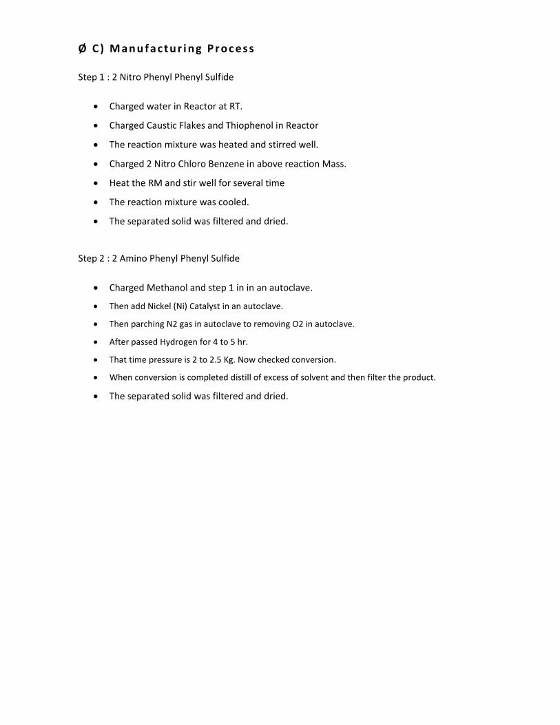
Ø C ) M a n u f a c t u r i n g P r o c e s s
Step 1 : 2 Nitro Phenyl Phenyl Sulfide
• Charged water in Reactor at RT.
• Charged Caustic Flakes and Thiophenol in Reactor
• The reaction mixture was heated and stirred well.
• Charged 2 Nitro Chloro Benzene in above reaction Mass.
• Heat the RM and stir well for several time
• The reaction mixture was cooled.
• The separated solid was filtered and dried.
Step 2 : 2 Amino Phenyl Phenyl Sulfide
• Charged Methanol and step 1 in in an autoclave.
• Then add Nickel (Ni) Catalyst in an autoclave.
• Then parching N2 gas in autoclave to removing O2 in autoclave.
• After passed Hydrogen for 4 to 5 hr.
• That time pressure is 2 to 2.5 Kg. Now checked conversion.
• When conversion is completed distill of excess of solvent and then filter the product.
• The separated solid was filtered and dried.
Page 26
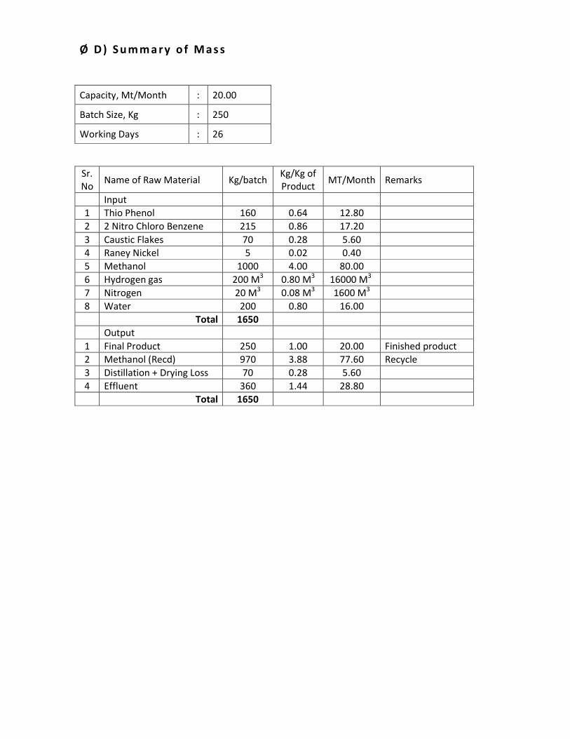
Ø D ) S u m m a ry o f M a s s
Capacity, Mt/Month : 20.00
Batch Size, Kg : 250
Working Days : 26
Sr.
No Name of Raw Material Kg/batch
Kg/Kg of
Product MT/Month Remarks
Input
1 Thio Phenol 160 0.64 12.80
2 2 Nitro Chloro Benzene 215 0.86 17.20
3 Caustic Flakes 70 0.28 5.60
4 Raney Nickel 5 0.02 0.40
5 Methanol 1000 4.00 80.00
6 Hydrogen gas 200 M3 0.80 M
3 16000 M
3
7 Nitrogen 20 M3 0.08 M
3 1600 M
3
8 Water 200 0.80 16.00
Total 1650
Output
1 Final Product 250 1.00 20.00 Finished product
2 Methanol (Recd) 970 3.88 77.60 Recycle
3 Distillation + Drying Loss 70 0.28 5.60
4 Effluent 360 1.44 28.80
Total 1650
Page 27
4 ) . D i b e n z o [ b , f ] [ 1 , 4 ] T h i a z e p i n - 1 1 ( 1 0 H ) - O n e
MW 227.28
Ethyl Chloro Formate
MW 108.52
PPA
+ HCl
MW 36.46
MW 201.28
2 Amino Phenyl Phenyl Sulfide
NH2
S
N
H
S
O
Dibenzo[b,f][1,4]Thiazepin-11(10H)-One
+
MW 46.09
C2H5OH
Ø B ) P r o c es s F l o w D i a g r am
2 Amino Phenyl Phenyl Sulfide
Ethyl Chloro formate
Poly Phosphoric Acid
Water
S T A G E
Process Emissions
Evaroparation Loss
Effulent
Phosphoric Acid Solution
F I N I S H
P R O D U C T
Page 28
Ø C ) M a n u f a c t u r i n g P r o c e s s
• Charged 2 Amino phenyl phenyl sulfide and Ethyl chloro formate in Reactor at RT
• The reaction mixture was heated and stirred well.
• Charged PPA and water in above reaction mass.
• Heat the RM and stir well for several time.
• Charged Toluene in above reaction mass
• Separate Organic layer and aqueous layer.
• Charged carbon in above organic layer and heat under stirring.
• Filter the reaction mass by sparker filter
• The reaction mixture was cooled.
• The separated solid was filtered wash with water and dried.
Ø D ) S u m m a ry o f M a s s
Capacity, Mt/Month : 20.00
Batch Size, Kg : 400
Working Days : 26
Sr.
No Name of Raw Material Kg/batch
Kg/Kg of
Product MT/Month Remarks
Input
1 2 Amino phenyl phenyl
sulfide 380 0.95 19.00
2 Poly Phosphoric Acid 1200 3.00 60.00
3 Ethyl Chloro formate 250 0.63 12.50
4 Toluene 1200 3.00 60.00
5 Carbon 20 0.05 1.00
6 Water 1000 2.50 50.00
Total 4050
Output
1 Final Product 400 1.00 20.00 Finished product
2 Toluene Recd 1150 2.88 57.50 Recycle
3 Drying + Distillation Loss 180 0.45 9.00
4 Residue 25 0.06 1.25
5 Waste Carbon 30 0.08 1.50
6 Effluent 2265 5.66 113.25
Total 4050
Page 29
5). 2-Chloro-1,3-bis(dimentylamino)trimethinium hexafluorophosphate
Ø A ) R e a c t i o n C h e m i s t ry
Polyphosporic Acid
MW 98.00
Hydrofluoric Gas
MW 20.00
H3PO4 + 6 HF H6F6.H3PO4
Hexa Fluoro Phosporic
Acid
MW 218.00
+
POCl3
NaOH
HFP
CH3
O
N H
CH3
Dimethyl Formamide
MW 93.09
N
ClCH3
CH3
N+
CH3
CH3PF6
-
2-Chloro-1,3-bis(dimethylamino)
triethinium hexafluoro phosphate Salt
MW 306.62
Cl
O
Cl
Chloro Acetyl Chloride
MW 112.94
Page 30
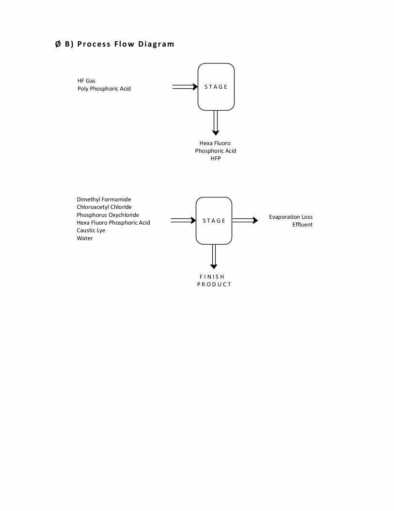
Ø B ) P r o c es s F l o w D i a g r am
HF Gas
Poly Phosphoric Acid S T A G E
Hexa Fluoro
Phosphoric Acid
HFP
Dimethyl Formamide
Chloroacetyl Chloride
Phosphorus Oxychloride
Hexa Fluoro Phosphoric Acid
Caustic Lye
Water
S T A G EEvaporation Loss
Effluent
F I N I S H
P R O D U C T
Page 31
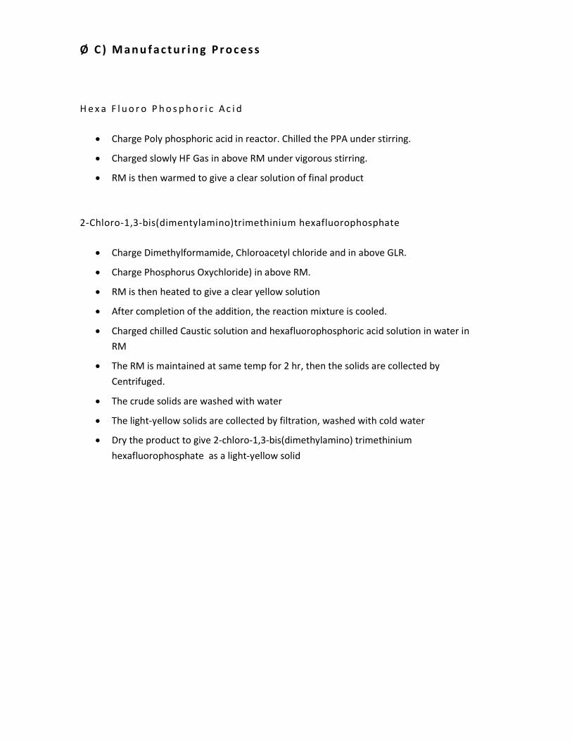
Ø C ) M a n u f a c t u r i n g P r o c e s s
H e x a F l u o r o P h o s p h o r i c A c i d
• Charge Poly phosphoric acid in reactor. Chilled the PPA under stirring.
• Charged slowly HF Gas in above RM under vigorous stirring.
• RM is then warmed to give a clear solution of final product
2-Chloro-1,3-bis(dimentylamino)trimethinium hexafluorophosphate
• Charge Dimethylformamide, Chloroacetyl chloride and in above GLR.
• Charge Phosphorus Oxychloride) in above RM.
• RM is then heated to give a clear yellow solution
• After completion of the addition, the reaction mixture is cooled.
• Charged chilled Caustic solution and hexafluorophosphoric acid solution in water in
RM
• The RM is maintained at same temp for 2 hr, then the solids are collected by
Centrifuged.
• The crude solids are washed with water
• The light-yellow solids are collected by filtration, washed with cold water
• Dry the product to give 2-chloro-1,3-bis(dimethylamino) trimethinium
hexafluorophosphate as a light-yellow solid
Page 32
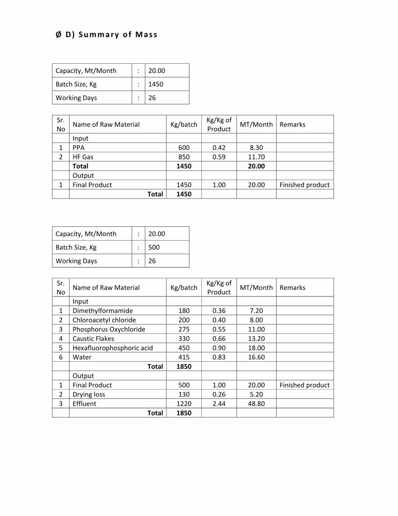
Ø D ) S u m m a ry o f M a s s
Capacity, Mt/Month : 20.00
Batch Size, Kg : 1450
Working Days : 26
Sr.
No Name of Raw Material Kg/batch
Kg/Kg of
Product MT/Month Remarks
Input
1 PPA 600 0.42 8.30
2 HF Gas 850 0.59 11.70
Total 1450 20.00
Output
1 Final Product 1450 1.00 20.00 Finished product
Total 1450
Capacity, Mt/Month : 20.00
Batch Size, Kg : 500
Working Days : 26
Sr.
No Name of Raw Material Kg/batch
Kg/Kg of
Product MT/Month Remarks
Input
1 Dimethylformamide 180 0.36 7.20
2 Chloroacetyl chloride 200 0.40 8.00
3 Phosphorus Oxychloride 275 0.55 11.00
4 Caustic Flakes 330 0.66 13.20
5 Hexafluorophosphoric acid 450 0.90 18.00
6 Water 415 0.83 16.60
Total 1850
Output
1 Final Product 500 1.00 20.00 Finished product
2 Drying loss 130 0.26 5.20
3 Effluent 1220 2.44 48.80
Total 1850
Page 33
6 ) . M e t a C h l o r o N i t r o B en z e n e
Ø A ) R e a c t i o n C h e m i s t ry
MW 123.11
NO2
Nitro Benzene
MW 70.91
+ HCl+
MW 36.46
Hydrochloric Acid
Cl2
Chlorine
NO2
Cl
MW 157.56
Meta Chloro
Nitro Benzene
Ø B ) P r o c es s F l o w D i a g r am
Nitro Benzene
Chlorine
MethanolS T A G E
Process Emissions
Evaporation Loss
Solvent Recovery
Residue
F I N I S H
P R O D U C T
Page 34
Ø C ) M a n u f a c t u r i n g P r o c e s s
• Charged Nitro Benzene in Glass Lined reactor.
• Then slowly purged of Chlorine gas with continues stirring. Keep temp 40oC to 50
oC.
• After completion of Chlorine addition, reaction mixture was heated and stirred
• Charged methanol in above organic mass.
• Chilled the reaction mass.
• Filter the solid mass and dry it.
Ø D ) S u m m a ry o f M a s s
Capacity, Mt/Month : 20.00
Batch Size, Kg : 500
Working Days : 26
Sr.
No Name of Raw Material Kg/batch
Kg/Kg of
Product MT/Month Remarks
Input
1 Nitro Benzene 410 0.82 16.40
2 Chlorine 255 0.51 10.20
3 Methanol 800 1.60 32.00
Total 1465 2.93 58.60
Output
1 Final Product 500 1.00 20.00 Finished product
2 Methanol Recd 750 1.50 30.00 Recycle
3 Drying + Distillation loss 190 0.38 7.60
4 Residue 25 0.05 1.00
Total 1465
Page 35
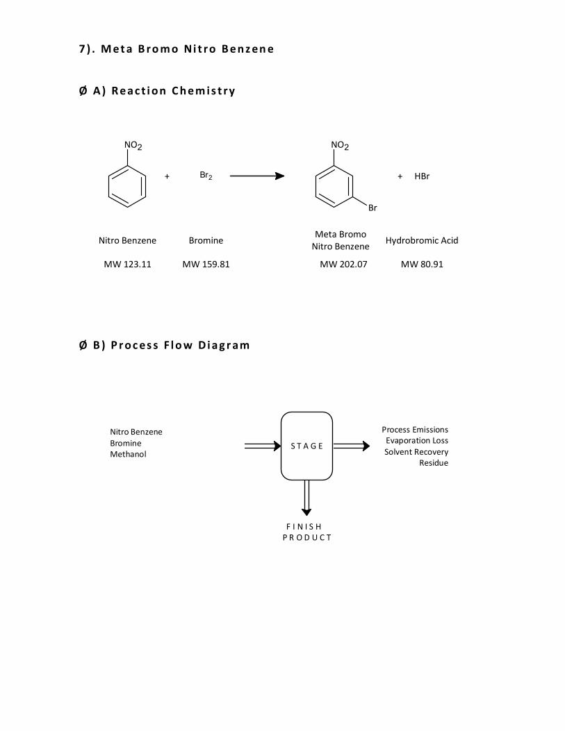
7 ) . M e t a B ro m o Ni t ro B e n z en e
Ø A ) R e a c t i o n C h e m i s t ry
MW 123.11
NO2
Nitro Benzene
MW 159.81
+ HBr+
MW 80.91
Hydrobromic Acid
Br2
Bromine
NO2
Br
MW 202.07
Meta Bromo
Nitro Benzene
Ø B ) P r o c es s F l o w D i a g r am
Nitro Benzene
Bromine
MethanolS T A G E
Process Emissions
Evaporation Loss
Solvent Recovery
Residue
F I N I S H
P R O D U C T
Page 36
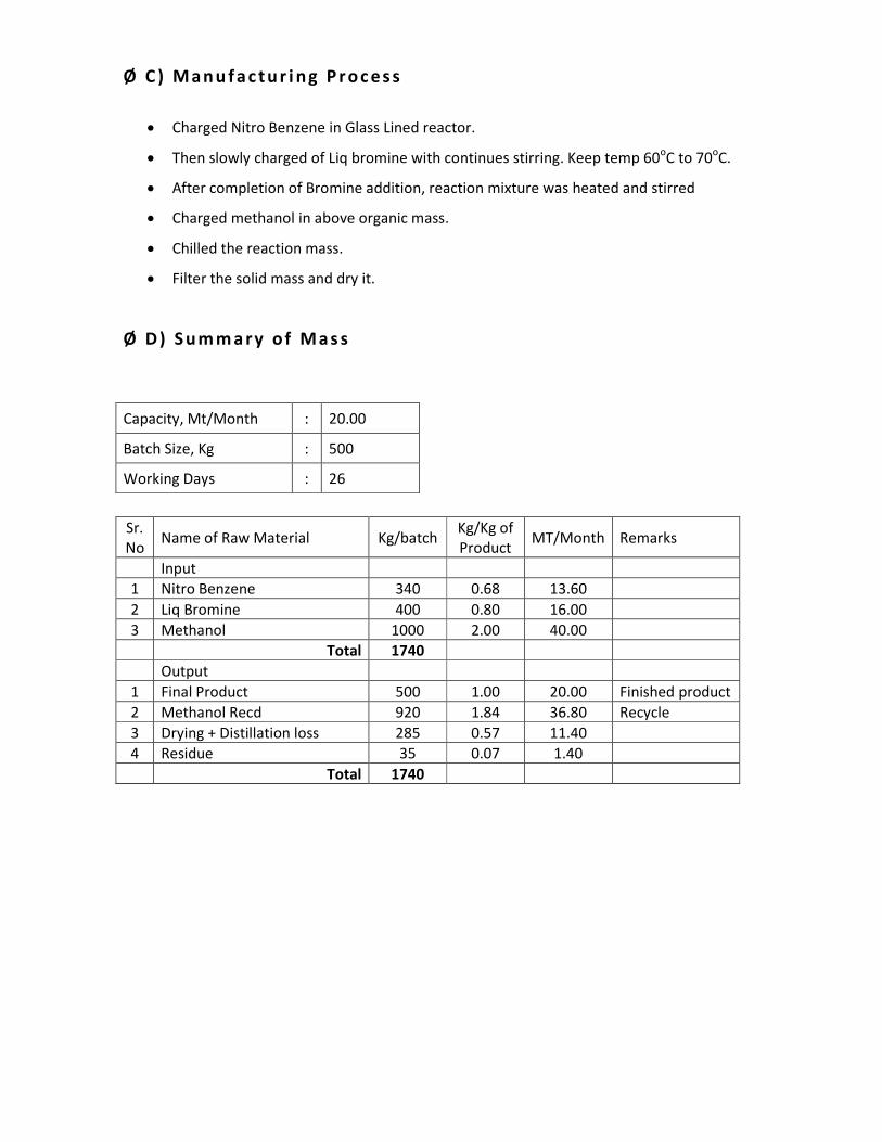
Ø C ) M a n u f a c t u r i n g P r o c e s s
• Charged Nitro Benzene in Glass Lined reactor.
• Then slowly charged of Liq bromine with continues stirring. Keep temp 60oC to 70
oC.
• After completion of Bromine addition, reaction mixture was heated and stirred
• Charged methanol in above organic mass.
• Chilled the reaction mass.
• Filter the solid mass and dry it.
Ø D ) S u m m a ry o f M a s s
Capacity, Mt/Month : 20.00
Batch Size, Kg : 500
Working Days : 26
Sr.
No Name of Raw Material Kg/batch
Kg/Kg of
Product MT/Month Remarks
Input
1 Nitro Benzene 340 0.68 13.60
2 Liq Bromine 400 0.80 16.00
3 Methanol 1000 2.00 40.00
Total 1740
Output
1 Final Product 500 1.00 20.00 Finished product
2 Methanol Recd 920 1.84 36.80 Recycle
3 Drying + Distillation loss 285 0.57 11.40
4 Residue 35 0.07 1.40
Total 1740
Page 37
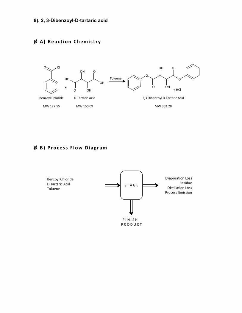
8). 2, 3-Dibenzoyl-D-tartaric acid
Ø A ) R e a c t i o n C h e m i s t ry
+
Toluene
O
OH
OHO
OH
OH
D Tartaric Acid
MW 150.09
O Cl
Benzoyl Chloride
MW 127.55
2,3 Dibenzoyl D Tartaric Acid
MW 302.28
O
O
OHO
O
OH
+ HCl
Ø B ) P r o c es s F l o w D i a g r am
Benzoyl Chloride
D Tartaric Acid
TolueneS T A G E
Evaporation Loss
Residue
Distillation Loss
Process Emission
F I N I S H
P R O D U C T
Page 38
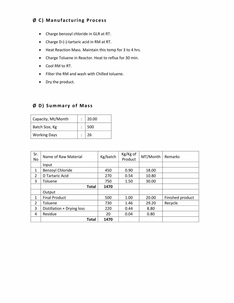
Ø C ) M a n u f a c t u r i n g P r o c e s s
• Charge benzoyl chloride in GLR at RT.
• Charge D-(-)-tartaric acid in RM at RT.
• Heat Reaction Mass. Maintain this temp for 3 to 4 hrs.
• Charge Toluene in Reactor. Heat to reflux for 30 min.
• Cool RM to RT.
• Filter the RM and wash with Chilled toluene.
• Dry the product.
Ø D ) S u m m a ry o f M a s s
Capacity, Mt/Month : 20.00
Batch Size, Kg : 500
Working Days : 26
Sr.
No Name of Raw Material Kg/batch
Kg/Kg of
Product MT/Month Remarks
Input
1 Benzoyl Chloride 450 0.90 18.00
2 D Tartaric Acid 270 0.54 10.80
3 Toluene 750 1.50 30.00
Total 1470
Output
1 Final Product 500 1.00 20.00 Finished product
2 Toluene 730 1.46 29.20 Recycle
3 Distillation + Drying loss 220 0.44 8.80
4 Residue 20 0.04 0.80
Total 1470
Page 39
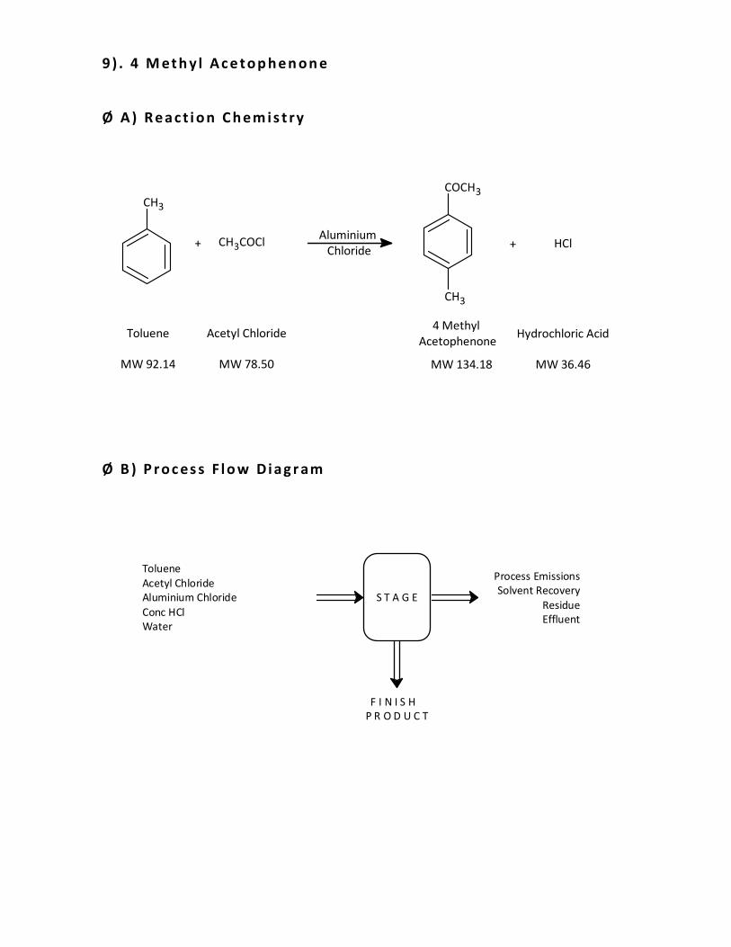
9 ) . 4 M et h y l A c e t o p h e n o n e
Ø A ) R e a c t i o n C h e m i s t ry
MW 92.14
CH3
Toluene
MW 78.50
+ HCl+
MW 36.46
Hydrochloric Acid
CH3COCl
Acetyl Chloride
COCH3
CH3
MW 134.18
4 Methyl
Acetophenone
Aluminium
Chloride
Ø B ) P r o c es s F l o w D i a g r am
Toluene
Acetyl Chloride
Aluminium Chloride
Conc HCl
Water
S T A G E
Process Emissions
Solvent Recovery
Residue
Effluent
F I N I S H
P R O D U C T
Page 40
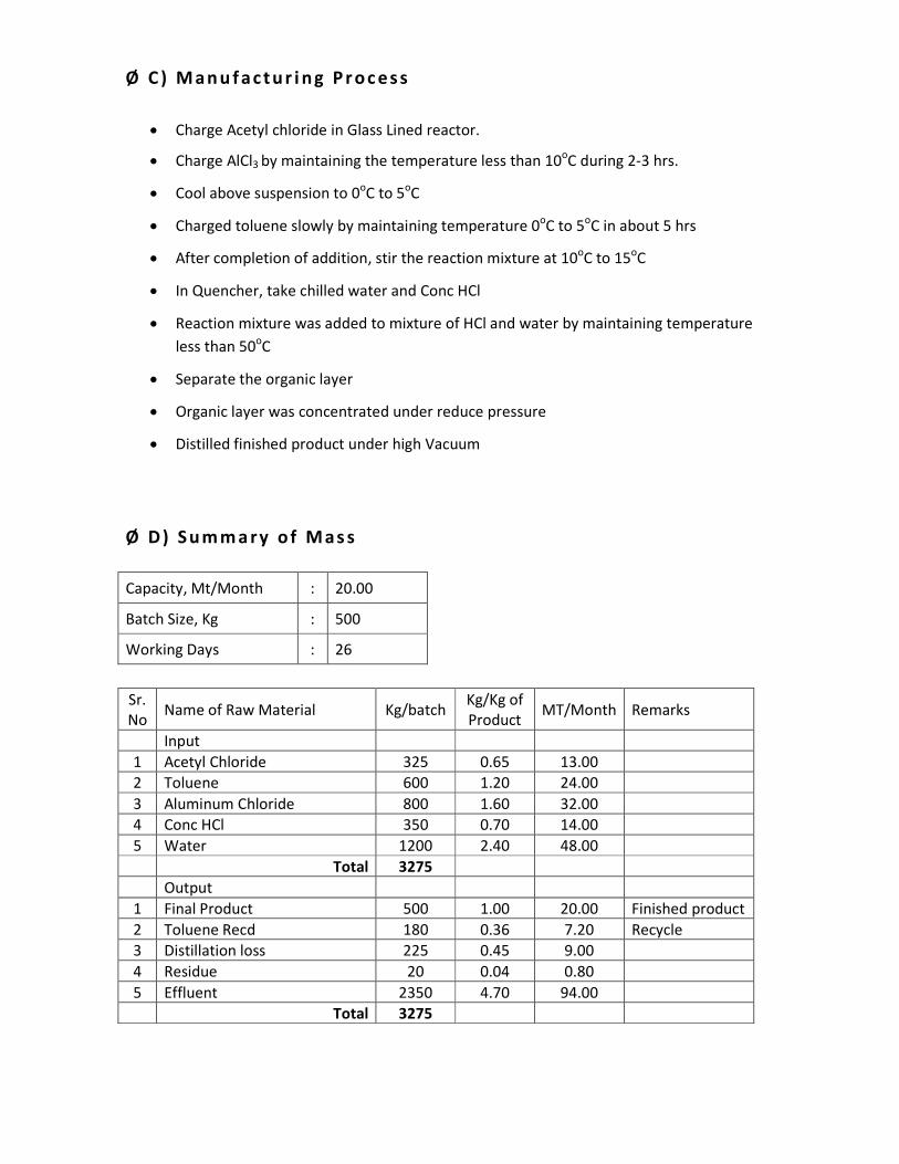
Ø C ) M a n u f a c t u r i n g P r o c e s s
• Charge Acetyl chloride in Glass Lined reactor.
• Charge AlCl3 by maintaining the temperature less than 10oC during 2-3 hrs.
• Cool above suspension to 0oC to 5
oC
• Charged toluene slowly by maintaining temperature 0oC to 5
oC in about 5 hrs
• After completion of addition, stir the reaction mixture at 10oC to 15
oC
• In Quencher, take chilled water and Conc HCl
• Reaction mixture was added to mixture of HCl and water by maintaining temperature
less than 50oC
• Separate the organic layer
• Organic layer was concentrated under reduce pressure
• Distilled finished product under high Vacuum
Ø D ) S u m m a ry o f M a s s
Capacity, Mt/Month : 20.00
Batch Size, Kg : 500
Working Days : 26
Sr.
No Name of Raw Material Kg/batch
Kg/Kg of
Product MT/Month Remarks
Input
1 Acetyl Chloride 325 0.65 13.00
2 Toluene 600 1.20 24.00
3 Aluminum Chloride 800 1.60 32.00
4 Conc HCl 350 0.70 14.00
5 Water 1200 2.40 48.00
Total 3275
Output
1 Final Product 500 1.00 20.00 Finished product
2 Toluene Recd 180 0.36 7.20 Recycle
3 Distillation loss 225 0.45 9.00
4 Residue 20 0.04 0.80
5 Effluent 2350 4.70 94.00
Total 3275
Page 41
10). N-{2-[4-(aminosulfonyl)phenyl]ethyl}-3-ethyl-4methyl-2-oxo-2,5-dihydro -
1H-pyrrole-1-carboxamide
Ø A ) R e a c t i o n C h e m i s t ry
N
CH3CH3
NHO
O
3-Ethyl-4-methyl-2-oxo-N-(2-phenylethyl)
-2,5-dihydro-1H-pyrrole-1-carboxamide
MW 272.34
N
CH3CH3
NHO
O SO2NH2
N-{2-[4-(Aminosulfonyl)phenyl]ethyl}-3-ethyl-4-
methyl-2-oxo-2,5-dihydro-1H-pyrrole-1-carboxamide
MW 351.42
Chloro Sulfonic Acid
+ +ClSO3H 2 NH3
Liq Ammonia
MW 116.52 MW 17.03
+NH4Cl H2O
MW 53.49 MW 18.02
+
Page 42
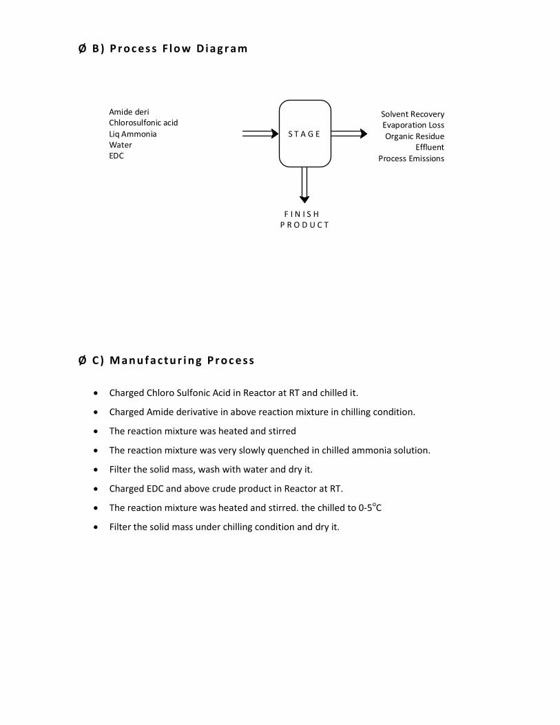
Ø B ) P r o c es s F l o w D i a g r am
Amide deri
Chlorosulfonic acid
Liq Ammonia
Water
EDC
S T A G E
Solvent Recovery
Evaporation Loss
Organic Residue
Effluent
Process Emissions
F I N I S H
P R O D U C T
Ø C ) M a n u f a c t u r i n g P r o c e s s
• Charged Chloro Sulfonic Acid in Reactor at RT and chilled it.
• Charged Amide derivative in above reaction mixture in chilling condition.
• The reaction mixture was heated and stirred
• The reaction mixture was very slowly quenched in chilled ammonia solution.
• Filter the solid mass, wash with water and dry it.
• Charged EDC and above crude product in Reactor at RT.
• The reaction mixture was heated and stirred. the chilled to 0-5oC
• Filter the solid mass under chilling condition and dry it.
Page 43
Ø D ) S u m m a ry o f M a s s
Capacity, Mt/Month : 10.00
Batch Size, Kg : 200
Working Days : 26
Sr.
No Name of Raw Material Kg/batch
Kg/Kg of
Product MT/Month Remarks
Input
1 Amide Derivative 160 0.80 8.00
2 Chloro Sulfonic Acid 200 1.00 10.00
3 Ammonia Solution 620 3.10 31.00
4 EDC 400 2.00 20.00
5 Water 200 1.00 10.00
Total 1580
Output
1 Final Product* 200 1.00 10.00 Finished product
2 EDC 340 1.70 17.00 Recycle
3 Distillation + Drying loss 160 0.80 8.00
4 Residue 5 0.03 0.26
5 Effluent 875 4.38 43.76
Total 1580
Page 44
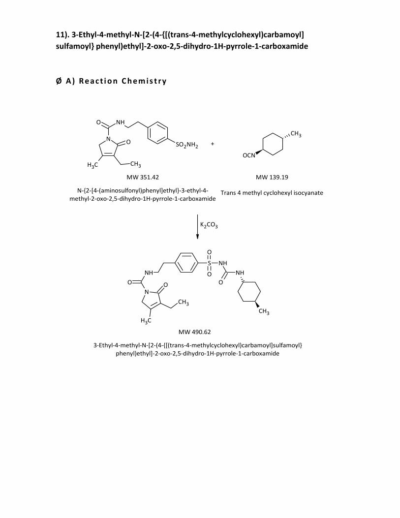
11). 3-Ethyl-4-methyl-N-[2-(4-{[(trans-4-methylcyclohexyl)carbamoyl]
sulfamoyl} phenyl)ethyl]-2-oxo-2,5-dihydro-1H-pyrrole-1-carboxamide
Ø A ) R e a c t i o n C h e m i s t ry
K2CO3
N
CH3
CH3
NH
O O
S
O
NH
O
O
NH
CH3
3-Ethyl-4-methyl-N-[2-(4-{[(trans-4-methylcyclohexyl)carbamoyl]sulfamoyl}
phenyl)ethyl]-2-oxo-2,5-dihydro-1H-pyrrole-1-carboxamide
MW 490.62
N
CH3CH3
NHO
O SO2NH2+
CH3
OCN
N-{2-[4-(aminosulfonyl)phenyl]ethyl}-3-ethyl-4-
methyl-2-oxo-2,5-dihydro-1H-pyrrole-1-carboxamideTrans 4 methyl cyclohexyl isocyanate
MW 351.42 MW 139.19
Page 45
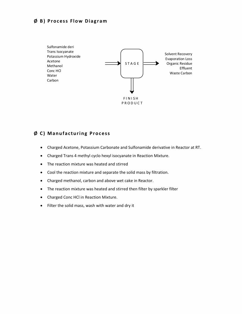
Ø B ) P r o c es s F l o w D i a g r am
Sulfonamide deri
Trans Isocyanate
Potassium Hydroxide
Acetone
Methanol
Conc HCl
Water
Carbon
Solvent Recovery
Evaporation Loss
Organic Residue
Effluent
Waste Carbon
F I N I S H
P R O D U C T
S T A G E
Ø C ) M a n u f a c t u r i n g P r o c e s s
• Charged Acetone, Potassium Carbonate and Sulfonamide derivative in Reactor at RT.
• Charged Trans 4 methyl cyclo hexyl isocyanate in Reaction Mixture.
• The reaction mixture was heated and stirred
• Cool the reaction mixture and separate the solid mass by filtration.
• Charged methanol, carbon and above wet cake in Reactor.
• The reaction mixture was heated and stirred then filter by sparkler filter
• Charged Conc HCl in Reaction Mixture.
• Filter the solid mass, wash with water and dry it
Page 46
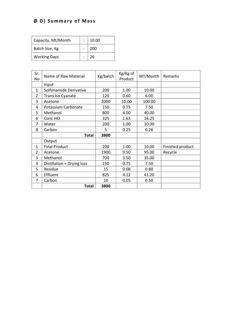
Ø D ) S u m m a ry o f M a s s
Capacity, Mt/Month : 10.00
Batch Size, Kg : 200
Working Days : 26
Sr.
No Name of Raw Material Kg/batch
Kg/Kg of
Product MT/Month Remarks
Input
1 Solfonamide Derivative 200 1.00 10.00
2 Trans Iso Cyanate 120 0.60 6.00
3 Acetone 2000 10.00 100.00
4 Potassium Carbonate 150 0.75 7.50
5 Methanol 800 4.00 40.00
6 Conc HCl 325 1.63 16.25
7 Water 200 1.00 10.00
8 Carbon 5 0.25 0.26
Total 3800
Output
1 Final Product 200 1.00 10.00 Finished product
2 Acetone 1900 9.50 95.00 Recycle
3 Methanol 700 3.50 35.00
4 Distillation + Drying loss 150 0.75 7.50
5 Residue 15 0.08 0.80
6 Effluent 825 4.12 41.20
7 Carbon 10 0.05 0.50
Total 3800
Page 47
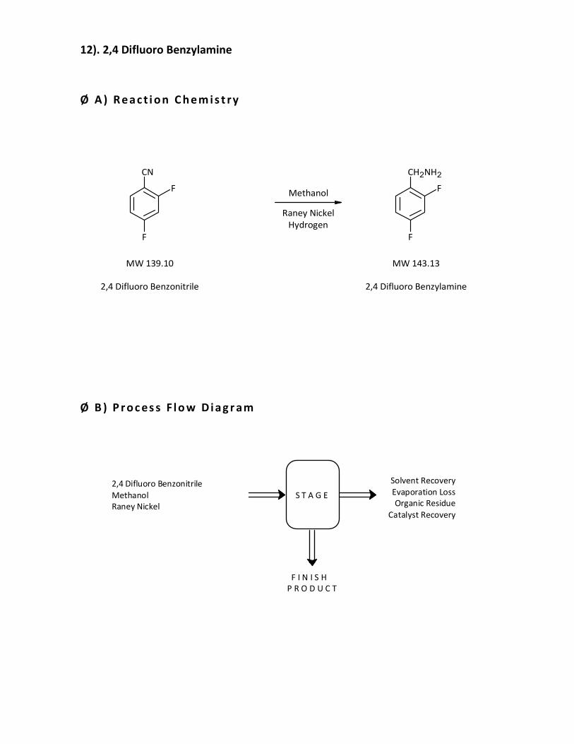
12). 2,4 Difluoro Benzylamine
Ø A ) R e a c t i o n C h e m i s t ry
2,4 Difluoro Benzonitrile
MW 139.10
F
CN
F
2,4 Difluoro Benzylamine
MW 143.13
F
CH2NH2
F
Methanol
Raney Nickel
Hydrogen
Ø B ) P r o c es s F l o w D i a g r am
2,4 Difluoro Benzonitrile
Methanol
Raney Nickel
S T A G E
Solvent Recovery
Evaporation Loss
Organic Residue
Catalyst Recovery
F I N I S H
P R O D U C T
Page 48
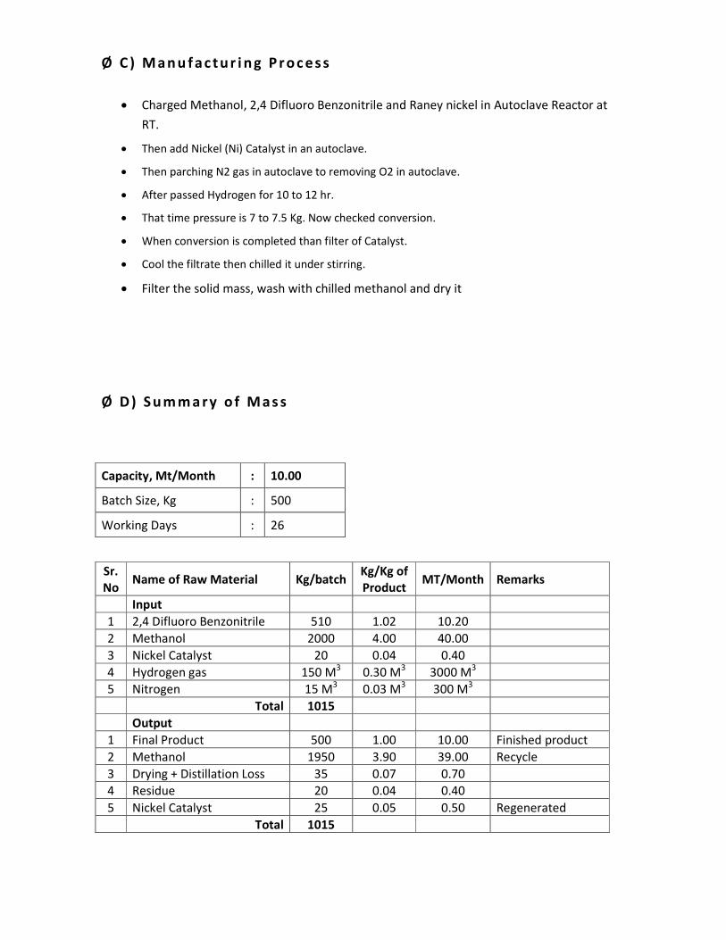
Ø C ) M a n u f a c t u r i n g P r o c e s s
• Charged Methanol, 2,4 Difluoro Benzonitrile and Raney nickel in Autoclave Reactor at
RT.
• Then add Nickel (Ni) Catalyst in an autoclave.
• Then parching N2 gas in autoclave to removing O2 in autoclave.
• After passed Hydrogen for 10 to 12 hr.
• That time pressure is 7 to 7.5 Kg. Now checked conversion.
• When conversion is completed than filter of Catalyst.
• Cool the filtrate then chilled it under stirring.
• Filter the solid mass, wash with chilled methanol and dry it
Ø D ) S u m m a ry o f M a s s
Capacity, Mt/Month : 10.00
Batch Size, Kg : 500
Working Days : 26
Sr.
No Name of Raw Material Kg/batch
Kg/Kg of
Product MT/Month Remarks
Input
1 2,4 Difluoro Benzonitrile 510 1.02 10.20
2 Methanol 2000 4.00 40.00
3 Nickel Catalyst 20 0.04 0.40
4 Hydrogen gas 150 M3 0.30 M
3 3000 M
3
5 Nitrogen 15 M3 0.03 M
3 300 M
3
Total 1015
Output
1 Final Product 500 1.00 10.00 Finished product
2 Methanol 1950 3.90 39.00 Recycle
3 Drying + Distillation Loss 35 0.07 0.70
4 Residue 20 0.04 0.40
5 Nickel Catalyst 25 0.05 0.50 Regenerated
Total 1015
Page 49
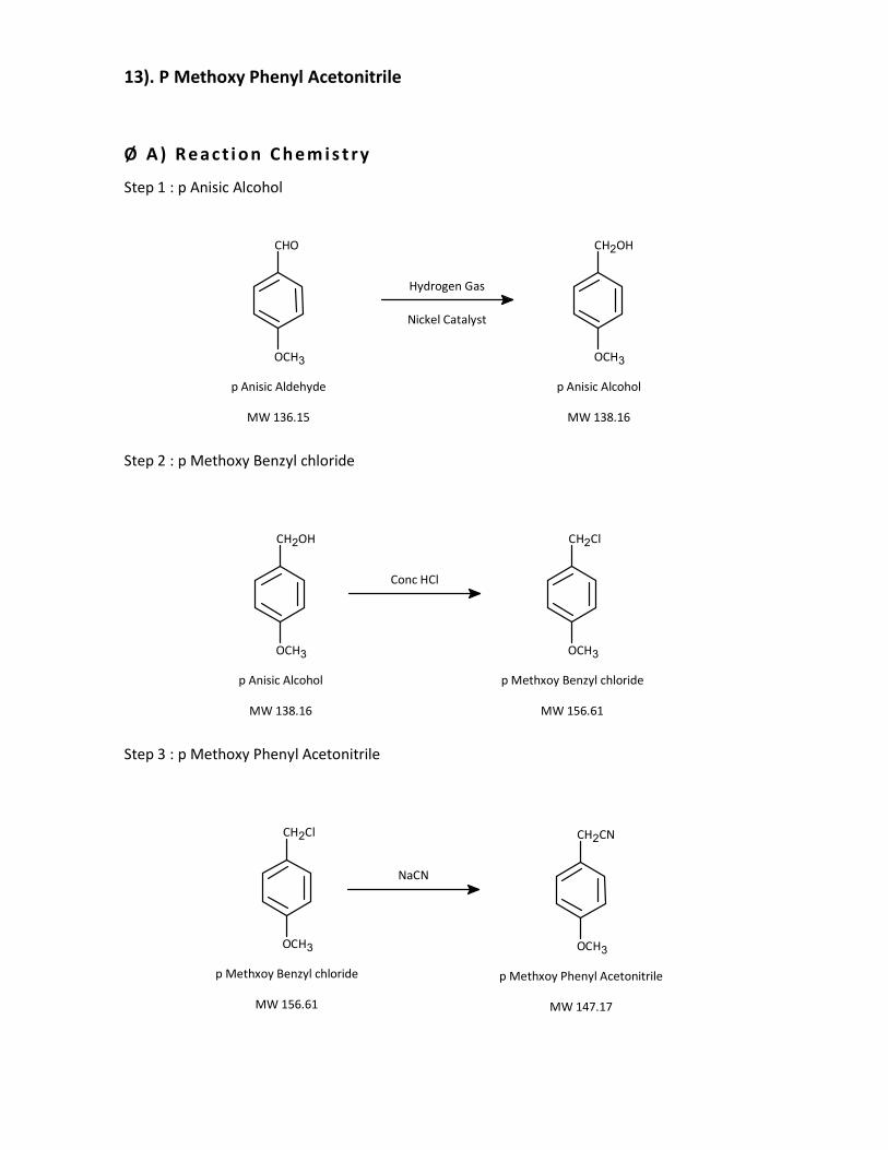
13). P Methoxy Phenyl Acetonitrile
Ø A ) R e a c t i o n C h e m i s t ry
Step 1 : p Anisic Alcohol
MW 136.15
p Anisic Aldehyde
Hydrogen Gas
Nickel Catalyst
CHO
OCH3
MW 138.16
p Anisic Alcohol
CH2OH
OCH3
Step 2 : p Methoxy Benzyl chloride
Conc HCl
MW 156.61
p Methxoy Benzyl chloride
CH2Cl
OCH3
MW 138.16
p Anisic Alcohol
CH2OH
OCH3
Step 3 : p Methoxy Phenyl Acetonitrile
NaCN
MW 147.17
p Methxoy Phenyl Acetonitrile
CH2CN
OCH3
MW 156.61
p Methxoy Benzyl chloride
CH2Cl
OCH3
Page 50
Ø B ) P r o c es s F l o w D i a g r am
Step 2 in Toluene
Sodium Cyanide
Sodium Chloride
Water
S T A G E 3Solvent Recovery
Effluent
F I N I S H
P R O D U C T
p Anisic Aldehyde
Hydrogen Gas
Nitrogen gas
Raney Nickel
S T A G E 1 Catalyst Recovery
Step 1
Conc HCl
Toluene
Water
S T A G E 2 Effluent
Page 51
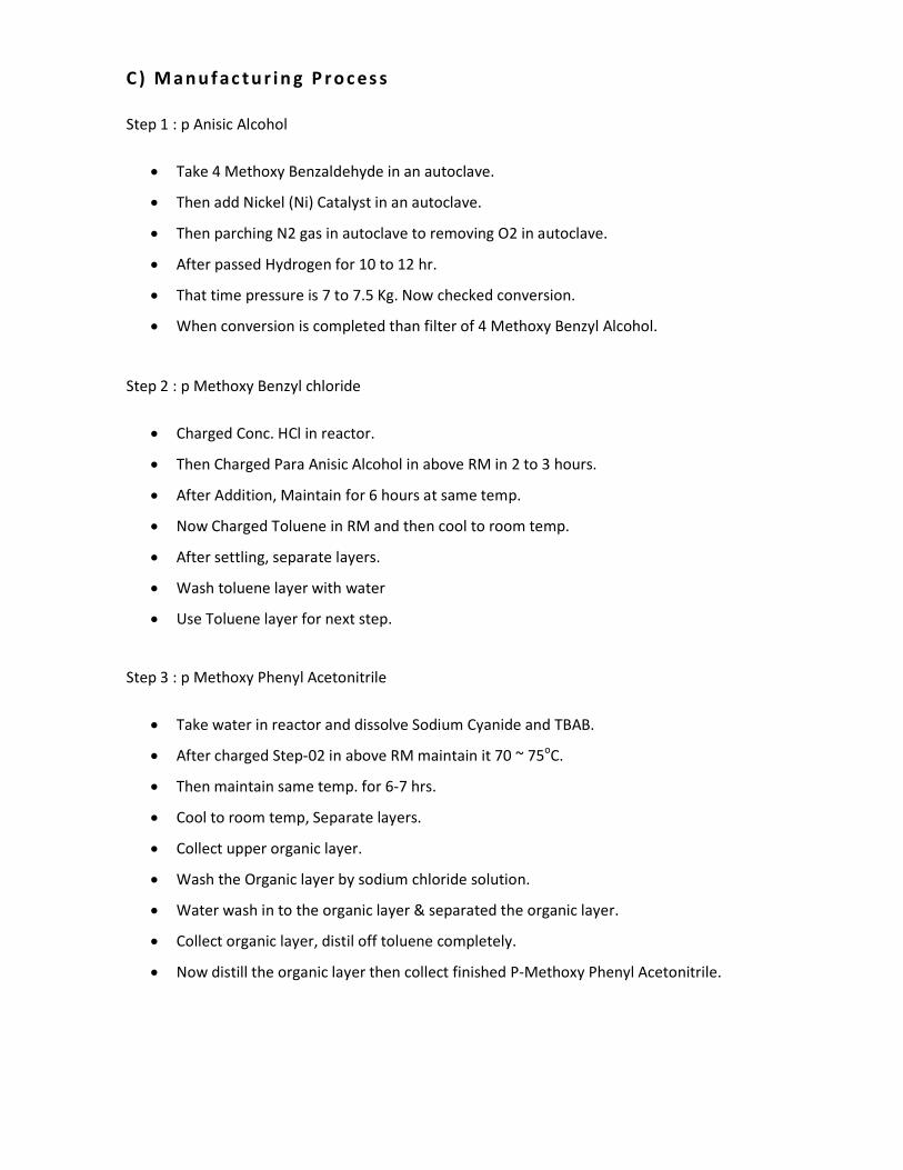
C ) M a n u f ac t u r i n g P r o c es s
Step 1 : p Anisic Alcohol
• Take 4 Methoxy Benzaldehyde in an autoclave.
• Then add Nickel (Ni) Catalyst in an autoclave.
• Then parching N2 gas in autoclave to removing O2 in autoclave.
• After passed Hydrogen for 10 to 12 hr.
• That time pressure is 7 to 7.5 Kg. Now checked conversion.
• When conversion is completed than filter of 4 Methoxy Benzyl Alcohol.
Step 2 : p Methoxy Benzyl chloride
• Charged Conc. HCl in reactor.
• Then Charged Para Anisic Alcohol in above RM in 2 to 3 hours.
• After Addition, Maintain for 6 hours at same temp.
• Now Charged Toluene in RM and then cool to room temp.
• After settling, separate layers.
• Wash toluene layer with water
• Use Toluene layer for next step.
Step 3 : p Methoxy Phenyl Acetonitrile
• Take water in reactor and dissolve Sodium Cyanide and TBAB.
• After charged Step-02 in above RM maintain it 70 ~ 75oC.
• Then maintain same temp. for 6-7 hrs.
• Cool to room temp, Separate layers.
• Collect upper organic layer.
• Wash the Organic layer by sodium chloride solution.
• Water wash in to the organic layer & separated the organic layer.
• Collect organic layer, distil off toluene completely.
• Now distill the organic layer then collect finished P-Methoxy Phenyl Acetonitrile.
Page 52
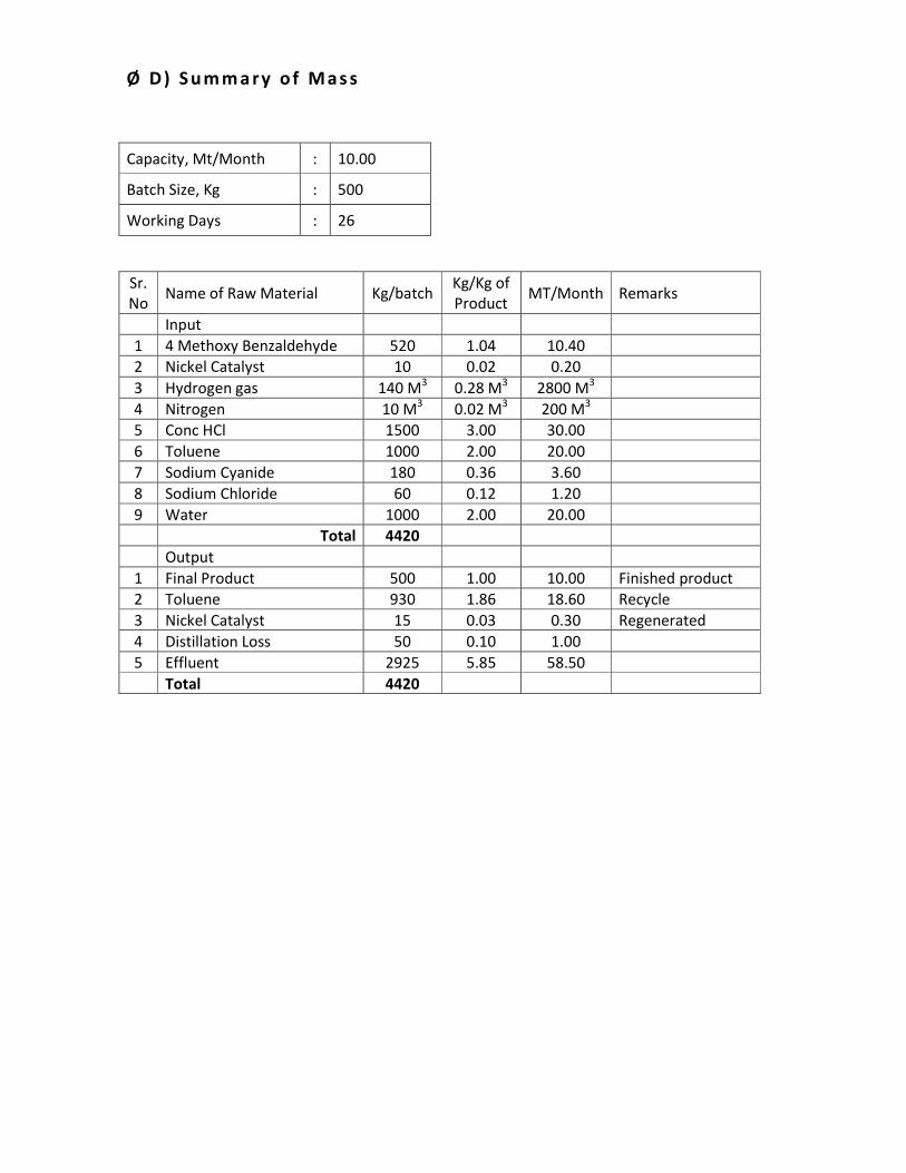
Ø D ) S u m m a ry o f M a s s
Capacity, Mt/Month : 10.00
Batch Size, Kg : 500
Working Days : 26
Sr.
No Name of Raw Material Kg/batch
Kg/Kg of
Product MT/Month Remarks
Input
1 4 Methoxy Benzaldehyde 520 1.04 10.40
2 Nickel Catalyst 10 0.02 0.20
3 Hydrogen gas 140 M3 0.28 M
3 2800 M
3
4 Nitrogen 10 M3 0.02 M
3 200 M
3
5 Conc HCl 1500 3.00 30.00
6 Toluene 1000 2.00 20.00
7 Sodium Cyanide 180 0.36 3.60
8 Sodium Chloride 60 0.12 1.20
9 Water 1000 2.00 20.00
Total 4420
Output
1 Final Product 500 1.00 10.00 Finished product
2 Toluene 930 1.86 18.60 Recycle
3 Nickel Catalyst 15 0.03 0.30 Regenerated
4 Distillation Loss 50 0.10 1.00
5 Effluent 2925 5.85 58.50
Total 4420
Page 53
14). 3-Trifluoromethyl Cinnamic Acid
Ø A ) R e a c t i o n C h e m i s t ry
MW 208.57
Intermediate Step
NH2
F3C
MW 161.12
3 Trifluoro methyl Aniline
NaNO2+ + 2 HCl
MW 68.99MW 36.46
2 H2O+ + NaCl
MW 18.02
MW 58.44
N+
N
F3C
Cl-
MW 216.16
3 Trifluoromethyl Cinnamic Acid
+
O OH
F3C
+
MW 53.06
H2O
MW 18.02
+
NaCl
MW 58.44
N2 +
MW 28.01
CH2 CN
NaOH
MW 39.99
+
+NH3
MW 17.03
Ø B ) P r o c es s F l o w D i a g r am
3 Trifluoomethyl Aniline
Sodium Nitrile
Conc HCl
Water
Acrylonitrile
Caustic Flakes
Conc Sulfuric Acid
S T A G E Effluent
Process Emissions
F I N I S H
P R O D U C T
Page 54
Ø C ) M a n u f a c t u r i n g P r o c e s s
• Charged Hydrochloric acid, Water and 3 Trifluoromethyl Aniline in Reactor at RT.
• Charged aqueous Sodium Nitrite in above reaction mixture at RT
• Charged slowly Acrylonitrile in above reaction mixture.
• Add Caustic flakes and water in above reaction mass.
• The reaction mixture was heated and stirred. Now cool the reaction mass.
• Dilute Sulfuric Acid was added to the reaction mixture
• The reaction mixture was cooled.
• The separated solid was filtered and dried.
Ø D ) S u m m a ry o f M a s s
Capacity, Mt/Month : 10.00
Batch Size, Kg : 200
Working Days : 26
Sr.
No Name of Raw Material Kg/batch
Kg/Kg of
Product MT/Month Remarks
Input
1 3 Trifluoromethyl Aniline 160 0.80 8.00
2 Conc HCl 265 1.33 13.30
3 Sodium Nitrite 80 0.40 4.00
4 Acrylonitrile 58 0.29 2.90
5 Caustic Flakes 50 0.25 2.50
6 Conc Sulfuric Acid 70 0.35 3.50
7 Water 200 1.00 10.00
Total 883
Output
1 Finish Product 200 1.00 10.00 Finished product
2 Drying Loss 50 0.25 2.50
3 Effluent 633 3.17 31.70
Total 883
Page 55
15). Ethyltrifluoro Acetate
Ø A ) R e a c t i o n C h e m i s t ry
FO
OH
F
F
MW 114.02
Trifluoro Acetic Acid
FO
O
F
F
CH3
MW 142.08
Ethyl Trifluoro Acetate
Ethanol
Sulfuric Acid
Sodium Carbonate
Water
Ø B ) P r o c es s F l o w D i a g r am
TrifluoroAcetic Acid
Ethanol
Sulfuric Acid
Water
Sodium carbonate
S T A G E
Solvent Recovery
Evaporation Loss
Organic Residue
Effluent
F I N I S H
P R O D U C T
Page 56
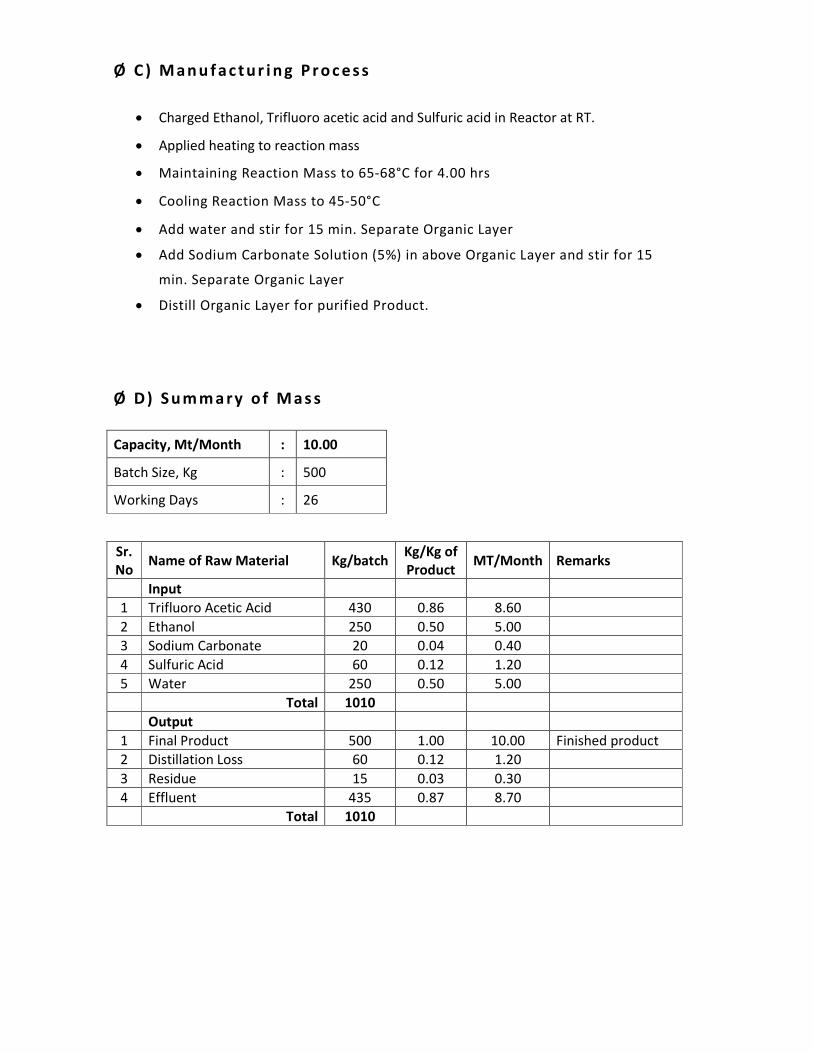
Ø C ) M a n u f a c t u r i n g P r o c e s s
• Charged Ethanol, Trifluoro acetic acid and Sulfuric acid in Reactor at RT.
• Applied heating to reaction mass
• Maintaining Reaction Mass to 65-68°C for 4.00 hrs
• Cooling Reaction Mass to 45-50°C
• Add water and stir for 15 min. Separate Organic Layer
• Add Sodium Carbonate Solution (5%) in above Organic Layer and stir for 15
min. Separate Organic Layer
• Distill Organic Layer for purified Product.
Ø D ) S u m m a ry o f M a s s
Capacity, Mt/Month : 10.00
Batch Size, Kg : 500
Working Days : 26
Sr.
No Name of Raw Material Kg/batch
Kg/Kg of
Product MT/Month Remarks
Input
1 Trifluoro Acetic Acid 430 0.86 8.60
2 Ethanol 250 0.50 5.00
3 Sodium Carbonate 20 0.04 0.40
4 Sulfuric Acid 60 0.12 1.20
5 Water 250 0.50 5.00
Total 1010
Output
1 Final Product 500 1.00 10.00 Finished product
2 Distillation Loss 60 0.12 1.20
3 Residue 15 0.03 0.30
4 Effluent 435 0.87 8.70
Total 1010
Page 57
16). Bupropion Hydrochloride
Ø A ) R e a c t i o n C h e m i s t ry
3 Chloro 2 Bromo Propiophenone Bupropion.HCl
MW 247.52 MW 276.20
Cl
OCH3
Br
(CH3)
3CNH
2
Cl
OCH3
NHCH3
CH3 CH3
. HCl
Ø B ) P r o c es s F l o w D i a g r am
3-Chloro-2'-Bromo Propiophenone
tert Butyl Amine
Tlouene
Water
Methanolic HCl
Iso Propyl Alcohol
Carbon
S T A G E 1
Solvent Recovery
Evaporation Loss
Process Emissions
Carbon Waste
F I N I S H
P R O D U C T
Page 58
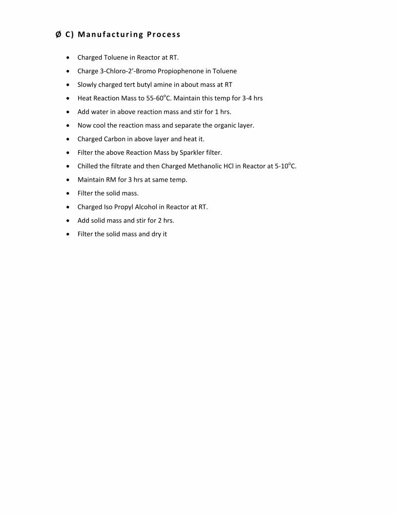
Ø C ) M a n u f a c t u r i n g P r o c e s s
• Charged Toluene in Reactor at RT.
• Charge 3-Chloro-2’-Bromo Propiophenone in Toluene
• Slowly charged tert butyl amine in about mass at RT
• Heat Reaction Mass to 55-60oC. Maintain this temp for 3-4 hrs
• Add water in above reaction mass and stir for 1 hrs.
• Now cool the reaction mass and separate the organic layer.
• Charged Carbon in above layer and heat it.
• Filter the above Reaction Mass by Sparkler filter.
• Chilled the filtrate and then Charged Methanolic HCl in Reactor at 5-10oC.
• Maintain RM for 3 hrs at same temp.
• Filter the solid mass.
• Charged Iso Propyl Alcohol in Reactor at RT.
• Add solid mass and stir for 2 hrs.
• Filter the solid mass and dry it
Page 59
Ø D ) S u m m a ry o f M a s s
Capacity, Mt/Month : 5.00
Batch Size, Kg : 400
Working Days : 26
Sr.
No Name of Raw Material Kg/batch
Kg/Kg of
Product MT/Month Remarks
Input
1 Toluene 1000 2.50 12.50
2 3-Chloro-2’-Bromo
Propiophenone 400 1.00 5.00
3 tert butyl amine 140 0.35 1.75
4 20% Methanolic HCl 325 0.81 4.06
5 Iso Propyl Alcohol 800 2.00 10.00
6 Carbon 10 0.03 0.13
7 Water 600 1.50 7.50
Total 3275
Output
1 Final Product 400 1.00 5.00 Finished product
2 Toluene (Recd) 955 2.39 11.94 Recycle
3 Isopropyl alcohol (Recd) 725 1.81 9.06 Recycle
4 Distillation + Drying loss 250 0.63 3.12
5 Residue 20 0.06 0.25
6 Effluent 910 2.28 11.40
7 Carbon Waste 15 0.04 0.19
Total 3275
Page 60
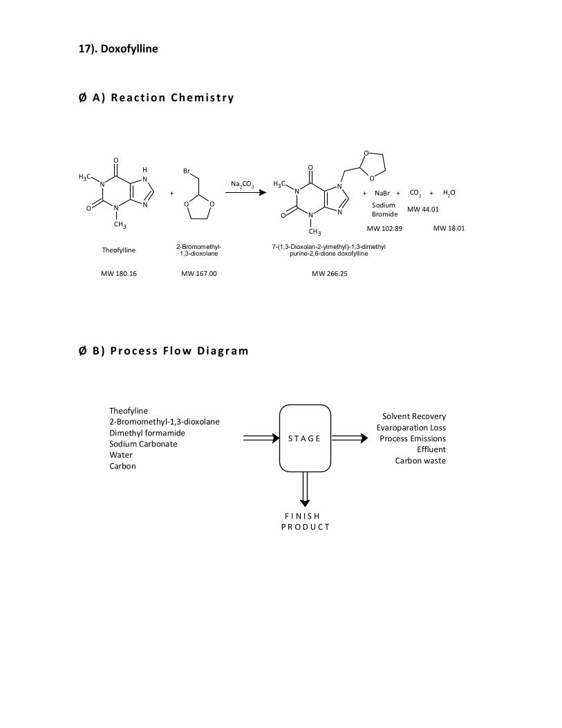
17). Doxofylline
Ø A ) R e a c t i o n C h e m i s t ry
2-Bromomethyl-1,3-dioxolane
MW 180.16
N
N
CH3
N
H
NO
CH3
O
Theofylline
MW 266.25
7-(1,3-Dioxolan-2-ylmethyl)-1,3-dimethyl purine-2,6-dione doxofylline
MW 167.00
+
Br
OO
N
N
CH3
N
NO
CH3
O
O
O
Na2CO
3
NaBr+
MW 102.89
Sodium
Bromide
CO2+
MW 44.01
H2O
MW 18.01
+
Ø B ) P r o c es s F l o w D i a g r am
Theofyline
2-Bromomethyl-1,3-dioxolane
Dimethyl formamide
Sodium Carbonate
Water
Carbon
S T A G E
Solvent Recovery
Evaroparation Loss
Process Emissions
Effluent
Carbon waste
F I N I S H
P R O D U C T
Page 61
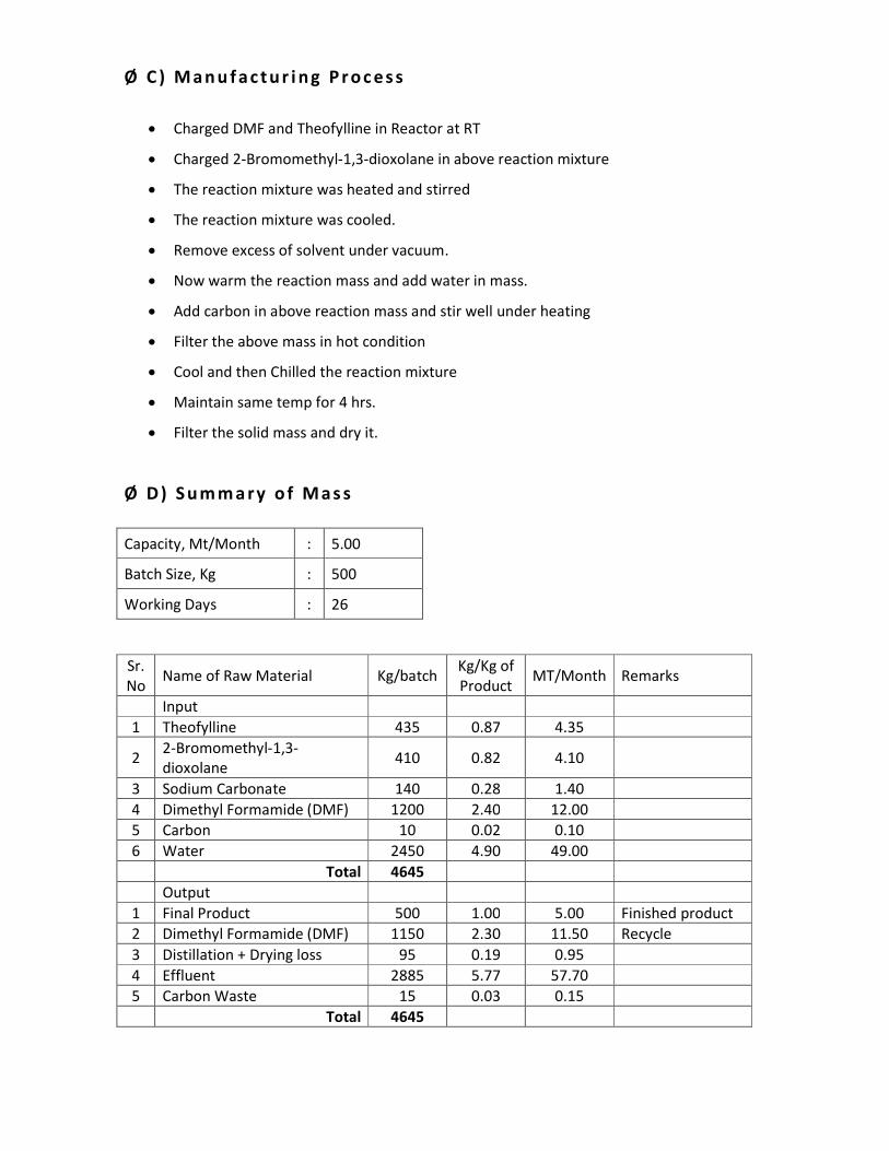
Ø C ) M a n u f a c t u r i n g P r o c e s s
• Charged DMF and Theofylline in Reactor at RT
• Charged 2-Bromomethyl-1,3-dioxolane in above reaction mixture
• The reaction mixture was heated and stirred
• The reaction mixture was cooled.
• Remove excess of solvent under vacuum.
• Now warm the reaction mass and add water in mass.
• Add carbon in above reaction mass and stir well under heating
• Filter the above mass in hot condition
• Cool and then Chilled the reaction mixture
• Maintain same temp for 4 hrs.
• Filter the solid mass and dry it.
Ø D ) S u m m a ry o f M a s s
Capacity, Mt/Month : 5.00
Batch Size, Kg : 500
Working Days : 26
Sr.
No Name of Raw Material Kg/batch
Kg/Kg of
Product MT/Month Remarks
Input
1 Theofylline 435 0.87 4.35
2 2-Bromomethyl-1,3-
dioxolane 410 0.82 4.10
3 Sodium Carbonate 140 0.28 1.40
4 Dimethyl Formamide (DMF) 1200 2.40 12.00
5 Carbon 10 0.02 0.10
6 Water 2450 4.90 49.00
Total 4645
Output
1 Final Product 500 1.00 5.00 Finished product
2 Dimethyl Formamide (DMF) 1150 2.30 11.50 Recycle
3 Distillation + Drying loss 95 0.19 0.95
4 Effluent 2885 5.77 57.70
5 Carbon Waste 15 0.03 0.15
Total 4645
Page 62
ANNEXURE – IV
_______________________________________________________________________
DETAILS OF WATER CONSUMPTION AND WASTEWATER GENERATION
Note: 1) High COD & High TDS effluent will be neutralized in tank and neutralized effluent will
be sent to common spray dryer of M/s. PETL, Panoli for further treatment & disposal.
2) Low COD & Low TDS effluent will be neutralized in tank and neutralized effluent will be sent
to CETP of M/s. PETL, Panoli for further treatment & disposal.
3) Domestic waste water will be sent to Septic Tank & Soak Pit.
Sr.
No.
Category Proposed Scenario (m3/day)
Water Consumption Waste Water
Generation
1. Industrial
Process 4.6 8.8
Boiler 4.0 0.5
Cooling 2.0 0.2
Washing 0.2 0.2
2. Gardening 2.0 -
3. Domestic 3.0 2.0
Total (Industrial) 10.8 9.7
Total 15.8 11.7
Page 63
Water Balance
Raw Water
15.8 KL/Day
Gardening
2.0 KL/Day
Domestic
3.0 KL/Day
Industrial
10.8 KL/Day
Process
4.6 KL/Day
Cooling
2.0 KL/Day
Washing
0.2 KL/Day
Boiler
4.0 KL/Day
3.9 KL/Day
ETP - Primery Treatment
CETP
for Further Treatment
2.0 KL/Day
Septic Tank/Soak Pik System
High COD/TDS
5.8 KL/Day
Common Spray Dryer Project
for Further Treatment
Page 64
ANNEXURE – V
_______________________________________________________________________
DETAILS OF EFFLUENT TREATMENT PLANT
M/s. Sigma Life science shall have an Effluent treatment plant consisting of primary treatment units.
The effluent confirming to inlet standards of CETP. The details of ETP are as follows.
PROCESS DESCRIPTION: ETP (EFFLUENT TREATMENT PLANT)
The treatment scheme is given below:
1) Stream-1 Low COD & Low TDS
Primary Treatment:
The waste water from unit will be brought to the treatment plant via a series of underground
pipelines. The waste water will be collected in the collection cum equalization tank. Two
numbers of tanks are proposed. One will in filling mode for equalization of waste water while
the other will be in pumping mode. The equalized wastewater is pumped to the flash mixer
for addition of chemicals like lime. From the flash mixer the waste water flows into the
flocculator where chemical flocs are formed by coagulation and flocculation by addition of
Alum/Ferrous sulphate and polyelectrolyte. These flocs are removed in the primary settling
tank. The underflow (sludge) from the primary settling tank is taken to sludge dewatering unit
(Sludge Drying Bed). Treated effluent will sent to CETP for further treatment & disposal.
The Domestic wastewater will be disposed of through septic tank & soak pit.
Effluent Treatment Plant (Dimension):
Sr. No. Name of the Unit Dimension Volume (m3) MOC
1. Collection Tank (1 Nos.) 2.0(m) x 2.0(m)x
1.0(m)
4.0 m3 RCC
2. Dosing Tank (1 Nos.) 1.0(m) x 1.0(m )x
1.0(m)
1.0 m3 RCC
3. Flash Mixer 1.0(m) x 1.0(m )x
1.0(m)
1.0 m3 RCC
4. Flocculator 1.0(m) x 1.0(m )x
1.0(m)
1.0 m3 RCC
5. Neutralization Tank 2.0(m) x 2.0(m)x
1.0(m)
4.0 m3 RCC
6. Primary Settling Tank 2.0(m) x 2.0(m)x
1.0(m)
4.0 m3 RCC
Page 65
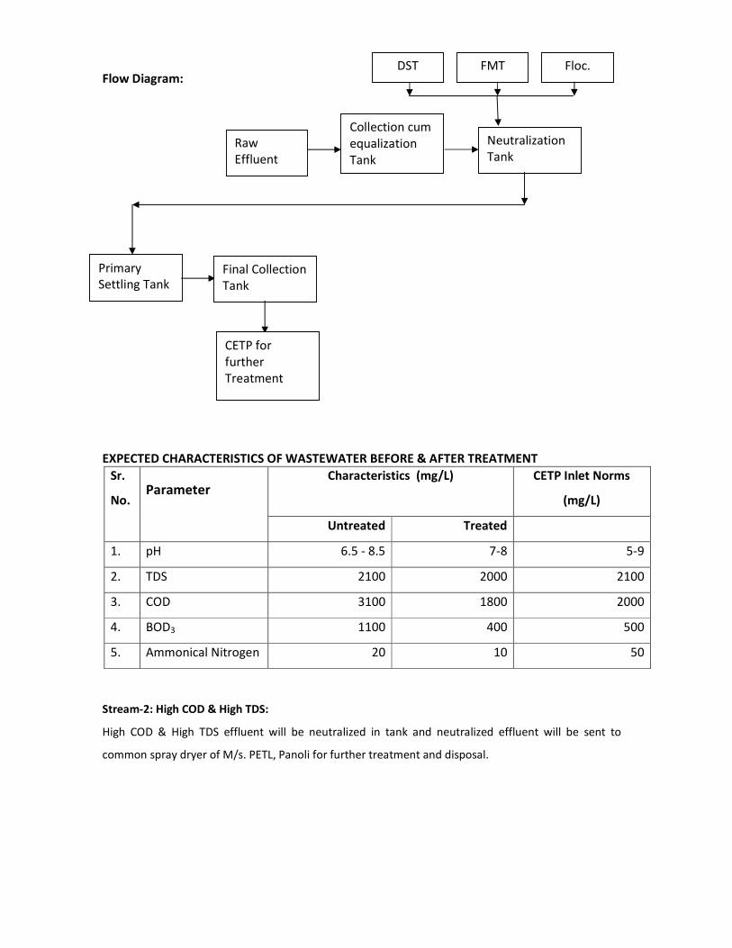
Flow Diagram:
EXPECTED CHARACTERISTICS OF WASTEWATER BEFORE & AFTER TREATMENT
Sr.
No. Parameter
Characteristics (mg/L) CETP Inlet Norms
(mg/L)
Untreated Treated
1. pH 6.5 - 8.5 7-8 5-9
2. TDS 2100 2000 2100
3. COD 3100 1800 2000
4. BOD3 1100 400 500
5. Ammonical Nitrogen 20 10 50
Stream-2: High COD & High TDS:
High COD & High TDS effluent will be neutralized in tank and neutralized effluent will be sent to
common spray dryer of M/s. PETL, Panoli for further treatment and disposal.
Raw
Effluent
Collection cum
equalization
Tank
Neutralization
Tank
Primary
Settling Tank Final Collection
Tank
CETP for
further
Treatment
DST FMT Floc.
Page 66
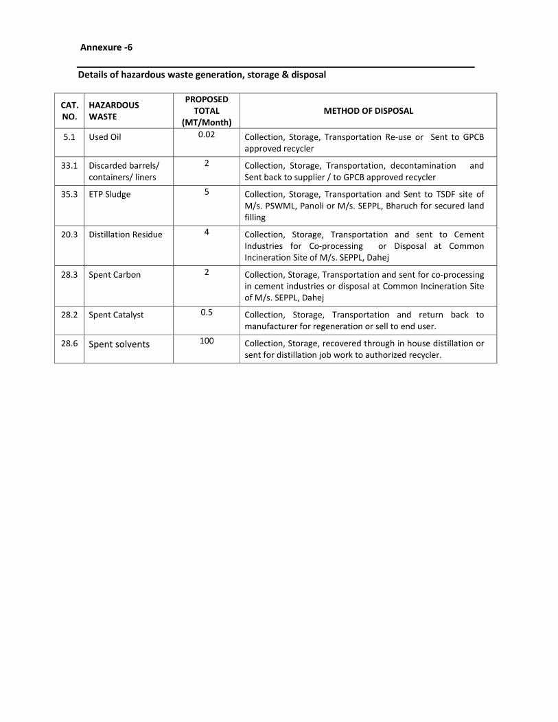
Annexure -6
Details of hazardous waste generation, storage & disposal
CAT.
NO.
HAZARDOUS
WASTE
PROPOSED
TOTAL
(MT/Month)
METHOD OF DISPOSAL
5.1 Used Oil 0.02 Collection, Storage, Transportation Re-use or Sent to GPCB
approved recycler
33.1 Discarded barrels/
containers/ liners
2 Collection, Storage, Transportation, decontamination and
Sent back to supplier / to GPCB approved recycler
35.3 ETP Sludge 5 Collection, Storage, Transportation and Sent to TSDF site of
M/s. PSWML, Panoli or M/s. SEPPL, Bharuch for secured land
filling
20.3 Distillation Residue 4 Collection, Storage, Transportation and sent to Cement
Industries for Co-processing or Disposal at Common
Incineration Site of M/s. SEPPL, Dahej
28.3 Spent Carbon 2
Collection, Storage, Transportation and sent for co-processing
in cement industries or disposal at Common Incineration Site
of M/s. SEPPL, Dahej
28.2 Spent Catalyst 0.5 Collection, Storage, Transportation and return back to
manufacturer for regeneration or sell to end user.
28.6 Spent solvents 100 Collection, Storage, recovered through in house distillation or
sent for distillation job work to authorized recycler.
Page 67
Annexure -7
Details of flue gas & proposed pollution control equipment
DETAILS OF FLUE GAS EMISSION THROUGH STACK ATTACHED TO BOILER
SR.
NO.
TYPE OF
STACK
PARTICULA
R
STACK
HEIGHT
(M)
STACK
DIAMETER
(M)
AIR EMISSION FUEL APCM
POLLUTANT CONC.
1. Thermic
Fluid
Heater
(2 Lac
Kcal)
STACK-1 30 0.6
PARTICULATE
MATTER
SO2
NOX
≤ 150
MG/NM3
≤ 100
PPM
≤ 50
PPM
Agro
Waste
Multi
cyclone
Separator
with Bag
Filter
2. Steam
boiler (1
TPH)
Agro
Waste
3. D G Set STACK 11 0.5 HSD --
DETAILS OF PROCESS EMISSION THROUGH VARIOUS VENTS
SR.
NO.
TYPE OF
STACK
AIR POLLUTION
CONTROL SYSTEM
HEIGHT (M) AIR EMISSION
POLLUTANT CONC.
1. Process Vent
Two Stage Scrubber 12.5 HCL
SO2
HBR
NH3
≤ 20 MG/NM3
≤ 40 MG/NM3
≤ 5 MG/NM3
≤ 175 MG/NM3
Page 68
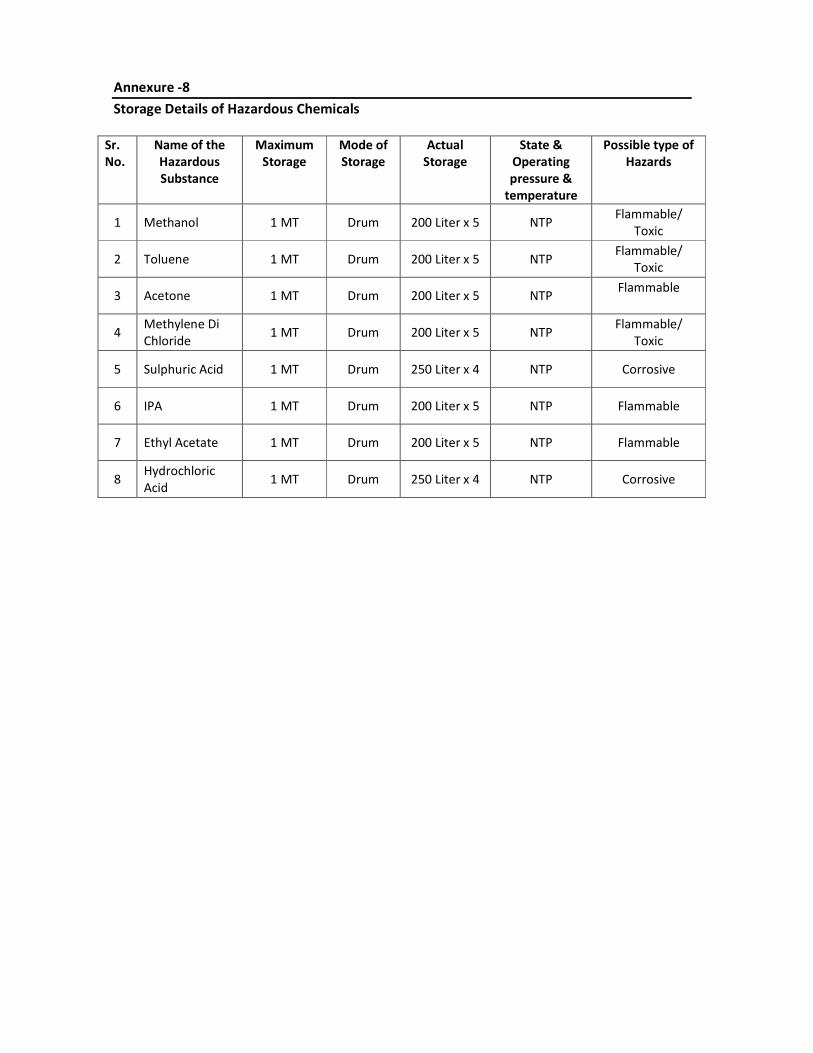
Annexure -8
Storage Details of Hazardous Chemicals
Sr.
No.
Name of the
Hazardous
Substance
Maximum
Storage
Mode of
Storage
Actual
Storage
State &
Operating
pressure &
temperature
Possible type of
Hazards
1 Methanol 1 MT Drum 200 Liter x 5 NTP Flammable/
Toxic
2 Toluene 1 MT Drum 200 Liter x 5 NTP Flammable/
Toxic
3 Acetone 1 MT Drum 200 Liter x 5 NTP Flammable
4 Methylene Di
Chloride 1 MT Drum 200 Liter x 5 NTP
Flammable/
Toxic
5 Sulphuric Acid 1 MT Drum 250 Liter x 4 NTP Corrosive
6 IPA 1 MT Drum 200 Liter x 5 NTP Flammable
7 Ethyl Acetate 1 MT Drum 200 Liter x 5 NTP Flammable
8 Hydrochloric
Acid 1 MT Drum 250 Liter x 4 NTP Corrosive
Page 69
Annexure – 9
Socio - Economic Impacts
1) Employment Opportunities
The manpower requirement for the proposed expansion project is being expected to generate
some permanent jobs and secondary jobs for the operation and maintenance of plant. This
will increase direct / indirect employment opportunities and ancillary business development
to some extent for the local population.
This phase is expected to create a beneficial impact on the local socio-economic environment.
2) Industries
Required raw materials and skilled and unskilled laborers will be utilized maximum from the
local area. The increasing industrial activity will boost the commercial and economical status
of the locality, to some extent.
3) Public Health
The company regularly examines, inspects and tests its emission from sources to make sure
that the emission is below the permissible limit. Hence, there will not be any significant
change in the status of sanitation and the community health of the area, as sufficient
measures have been taken and proposed under the EMP.
4) Transportation and Communication
Since the existing factory is having proper linkage for the transport and communication, the
development of this project will not cause any additional impact.
In brief, as a result of the proposed there will be no adverse impact on sanitation,
communication and community health, as sufficient measures have been proposed to be
taken under the EMP. The proposed scenario is not expected to make any significant change
in the existing status of the socio - economic environment of this region.
Page 70
Annexure-10
__________________________________________________________________________
Proposed Terms of Reference for EIA Studies
1. Project Description
• Justification of project.
• Promoters and their back ground
• Project site location along with site map of 5 km area and site details providing various
industries, surface water bodies, forests etc.
• Project cost
• Project location and Plant layout.
• Existing infrastructure facilities
• Water source and utilization including proposed water balance.
• List of Products & their capacity
• Details of manufacturing process of proposed products
• List of hazardous chemicals
• Mass balance of each product
• Storage and Transportation of raw materials and products.
2. Description of the Environment and Baseline Data Collection
• Micrometeorological data for wind speed, direction, temperature, humidity and rainfall in
5 km area.
• Existing environmental status Vis a Vis air, water, noise, soil in 5 km area from the project
site.
• Ground water quality at 5 locations within 5 km.
• Complete water balance
3. Socio Economic Data
• Existing socio-economic status, land use pattern and infrastructure facilities available in the
study area were surveyed.
4. Impacts Identification And Mitigatory Measures
• Identification of impacting activities from the proposed project during construction and
operational phase.
• Impact on air and mitigation measures including green belt
• Impact on water environment and mitigation measures
• Soil pollution source and mitigation measures
• Noise generation and control.
• Solid waste quantification and disposal.
• Control of fugitive emissions
5. Environmental Management Plan
• Details of pollution control measures
• Environment management team
• Proposed schedule for environmental monitoring including post project
Page 71
6. Risk Assessment
• Objectives, Philosophy and methodology of risk assessment
• Details on storage facilities
• Process safety, transportation, fire fighting systems, safety features and emergency
capabilities to be adopted.
• Identification of hazards
• Consequence analysis
• Recommendations on the basis of risk assessment done
• Disaster Management Plan.
7. Information for Control of Fugitive Emissions
8. Information on Rain Water Harvesting
9. Green Belt Development plan