Filtration Chemical Industry Digest. April 2014 56 Barry Perlmutter is the President and Managing Director of BHS-Sonthofen Inc., a subsidiary of BHS-Sonthofen GmbH. Barry has over 30 years of technical engineering and business marketing experience in the field of solid-liquid separation including filtration and centrifugation and process drying. Barry began his career with the US Environmental Protection Agency. He has a MS degree from the School of Engineering at Washington University, St. Louis and an MBA from the University of Illinois. Framework for Selecting Solid-Liquid Filtration Technologies for Particle Fines Removal Barry Perlmutter Abstract In the manufacturing of chemicals, petrochemicals, pharmaceuticals, etc., after the initial mixing-reactions, there is always the necessity to remove the mother liquor from the process slurry. In some cases, the liquid is the valuable component, some cases it is the solids and in other cases it is both compounds. The nature of the requirements determines the type of equipment needed for the separation process. This paper pro- vides an overview of separation equipment and then continues with a detailed view of technologies that can remove – recover small particle fines. Chemical Industry Digest. April 2014
Transcript
Filtration
Chemical Industry Digest. April 201456
Barry Perlmutter is the President and Managing Director of BHS-Sonthofen Inc., a subsidiary of BHS-Sonthofen GmbH. Barry has over 30 years of technical engineering and business marketing experience in the field of solid-liquid separation including filtration and centrifugation and process drying. Barry began his career with the US Environmental Protection Agency. He has a MS degree from the School of Engineering at Washington University, St. Louis and an MBA from the University of Illinois.
Framework for Selecting Solid-Liquid Filtration Technologies for Particle Fines Removal
Barry Perlmutter
Abstract
In the manufacturing of chemicals, petrochemicals, pharmaceuticals, etc., after the initial mixing-reactions, there is always the necessity to remove the mother liquor from the process slurry. In some cases, the liquid is the valuable component, some cases it is the solids and in other cases it is both compounds. The nature of the requirements determines the type of equipment needed for the separation process. This paper pro-vides an overview of separation equipment and then continues with a detailed view of technologies that can remove – recover small particle fines.
Chemical Industry Digest. April 2014
Chemical Industry Digest. April 2014
Filtration
57
Filtration, pressure or vacuum, is the art of finding a filter media which allows the liquid to pass through while retaining the solids. The driving force may be
gravity, vacuum, pressure or centrifugal.
Types of filtration systems: Batch filtersAutopress: This horizontal pressure filter operates as
a contained filter press. Circular plates with welded metal or synthetic media are contained in a pressurized hous-ing. This allows for pressure filtration, cake washing and vacuum or pressure drying. After the cycle is completed, the housing is moved and automatic cake discharge is done via scraper knives that move between the plates.
Bag filters: A bag with a connection to a high pressure inlet held captive in a metal cage. Filtrate runs through the bag and the solids stay inside.
Basket centrifuge: A metal basket rotating at centrifu-gal speeds and a cloth bag is fitted inside the basket. The drive mechanism runs the basket up to high speeds and feed is poured into the basket. Filtrate runs through the basket and is collected in an outer mantle. When suffi-cient solids have collected inside the bag, the machine is slowed to allow a mechanical scraper to remove the bulk of the solids (a “heel” stays behind). In a horizon-tal version, the peeler centrifuge or inverting centrifuge, the bulk of the cake can be removed without slowing the machine.
Cartridge filters: Pressure vessels which are fitted with filter cartridges where the flow is from the outside inwards. Cartridges are available in cleanable or dispos-able form. A wide variety of materials, pore size and physical sizes are available.
Filter press: The original filter presses were of the “plate and frame” construction. Modern presses use al-most exclusively “recessed plates”. A very wide variety of sizes, configurations, plate supports and degrees of au-tomation exist.
Leaf filter: Leaf filters consist of a pressure vessel in-side which a number of filter leafs are vertically mounted. The leaves are normally metal and fitted with a synthetic media. For removal of the solids different arrangements exist, ranging from opening the bottom of the vessel to mechanically spinning or vibrating the cake into a chute.
Membrane presses: The mem-brane press is a filter press but in-stead of having drainage grooves in the plates, the plates are fitted with an elastomer sheet which is inflated. By inflating the sheet at the end of
the filter cycle, the cake will be squeezed, for lower cake moisture.
Nutsche filter: Circular or rectangular filters with a drainage bottom onto which a filter medium is fastened. If the drainage section is connected to a vacuum source the filters are open top. If they are closed at the top, they can be pressurized and thus benefit from a higher driving force.
Types of filtration systems: Continuous filtersDisc filter: These consist of a flat disc mounted on a
hollow shaft. The disc is made of metal and has on either side an open cloth support structure which connects with the hollow shaft which carries the filtrate. A filter cloth is fastened to the disc and the hollow shaft connects to a vacuum source. The disc, usually 30% submerged, ro-tates slowly in a feed trough where it picks up the solids, which can later be scraped off just prior to re-entry into the feed trough.
Rotary pressure filter: The Rotary pressure filter is a continuously operating unit for pressure filtration, cake washing and drying of slurries up to 50% solids. The filter has a rotating drum inside a housing. The drum has cells within which are cell inserts fitted with the fil-ter media. Filtration is conducted via pressure of up to 6 bar. Positive displacement washing or counter-current washing follows filtration. Finally, the cake is dried by blowing hot or ambient gas through the cake. The Filter has a uniquely designed discharge system, which pro-vides for atmospheric discharge from pressure filtration. After automatic cake discharge, the filter cloth is washed; the clean filter cloth the re-enters the feeding /filtration zone thereby continuing the process. All solvent and gas streams can be recovered separately and reused in the process to minimize their consumption.
Pusher centrifuge: Horizontally mounted filtering centrifuge with a filter cage made of metal bars the small-est opening of which is about 100 micron. Inside the cage is a “pusher” arrangement, basically a sturdy ring which lies very close to the filter medium. The ring is connected to a central shaft which rotates at the same speed as the filter cage but reciprocates causing the collected solids to be pushed out of the machine. Multi stage machines ex-ist where the solids are pushed onto the second or third
stage which is each time of a larger diameter. The higher linear velocity as well as the tumbling action can be beneficial for dewatering and/or cake washing, although it may cause par-ticle fines requiring further clarifica-tion.
Candle filters provide for thin-cake pressure filtration, cake washing, drying, reslurry and automatic dis-charge as well as heel filtration in an enclosed, pressure vessel.
Filtration
Chemical Industry Digest. April 201458
Rotary vacuum drum filter: The original rotary drum filter consisted of a cylindrical drum, fitted with a drain-age grid and filter cloth. The drum had perforations and was connected to a vacuum source. The drum itself was mounted on a horizontal shaft and submerged for about 30% in a feed trough. The vacuum caused the liquor phase to be sucked through the cloth, leaving the solids behind as a filter cake. The cake was scraped off just before re-entering the feed trough.
Vacuum belt filter: The two main types are carrier belt and tray (fixed or indexing). These filters have a contin-uous belt as the filter medium which is subjected to a vacuum source. Feed is introduced at one end, where it is normally allowed to settle under grav-ity for a few seconds. The suspension is then subjected to full vacuum. Since the cake thickness can be controlled by adjusting the speed of travel or index-ing time, the optimum cake thickness to obtain the required residual mois-ture and / or cake washing efficiency is achieved. The horizontal configura-tion makes this filter one of the most efficient cake washing filters.
Clarification of slurries & recovery of fine solids
As processes have become more sophisticated and quality requirements increased, there is a trend to be able to remove the residual particle fines. These fines are very small, typically, smaller than 1 – 5 micron range and are very low in concentration down to ppm levels.
Candle filters and pressure plate filters are installed for clarification and recovery applications from liquids with low solids content. The candle filters are vertical candles while the pressure plate filters are horizontal plates. The cake structure as well as the process parameters deter-mines the optimum thin-cake technology.
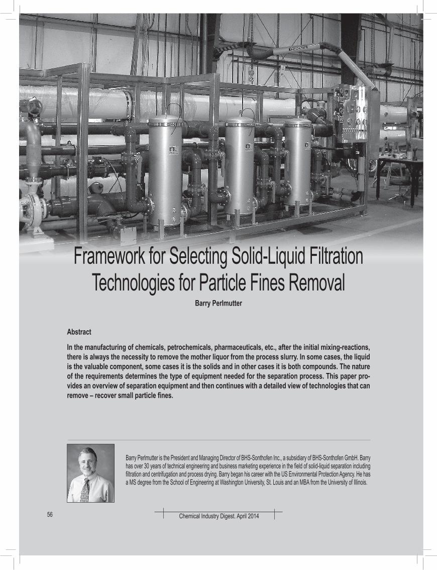
Fig 1: BHS Candle showing gas flow to expand the filter media sock for cake discharge
Fig 2: BHS candle filter
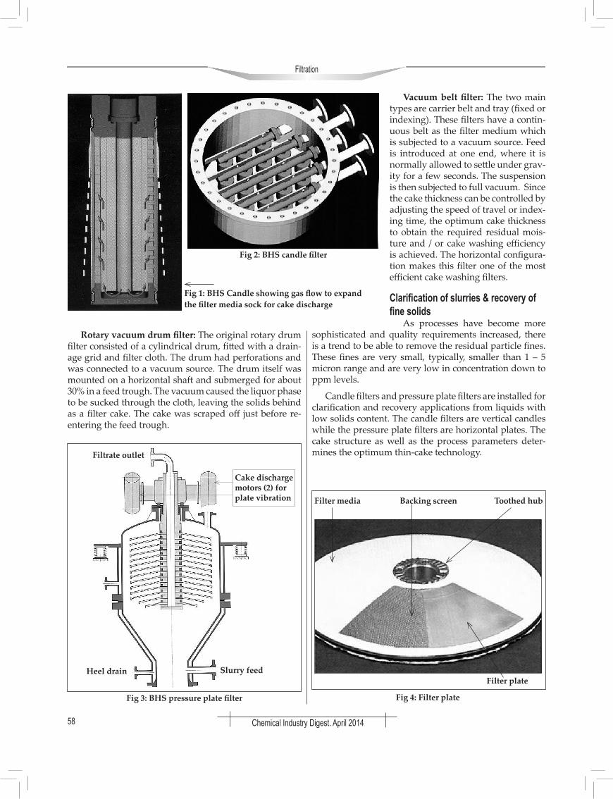
Fig 3: BHS pressure plate filter
Filtrate outlet
Cake discharge motors (2) for plate vibration
Slurry feedHeel drain
Fig 4: Filter plate
Filter plate
Filter media Backing screen Toothed hub
Chemical Industry Digest. April 2014
Filtration
59
Description and operation of the candle filterCandle filters provide for thin-cake pressure filtration,
cake washing, drying, reslurry and automatic discharge as well as heel filtration in an enclosed, pressure vessel. Units are available from 0.17 m2 up to 200 m2 of filter area per vessel.
Filter Candles & MediaThe filter candles, as shown in Figure 1, consist of
three components: single-piece dip pipe for filtrates and gas, perforated core with outer support tie rods and filter sock. The filtrate pipe is the full length of the candle and ensures high liquid flow as well as maximum distribution of the gas during cake discharge. The candle can be a syn-thetic, stainless steel or higher alloys. The outer support tie rods provide for an annular space between the media and the core for a low pressure drop operation and ef-ficient gas expansion of the filter media sock for cake dis-charge. The filter media is synthetic with clean removal efficiency to less than 1 micron (µm). As the cake builds up, removal efficiencies improve to less than 0.5 µm.
Filter vessel & candle registersThe candle filter vessel is constructed of stainless steel
or higher alloys. Within the vessel are horizontal mani-folds called candle registers. Each candle is connected to a register with a positive seal to prevent bypass. Each register may contain from 1-20 candles depending upon the filter size. The registers convey the liquid filtrate in the forward direction as well as the pressure gas in the reverse direction for filter media sock expansion. Each
register is controlled with automated valves to ensure optimum flow in both directions. Figure 2 illustrates the candle filter vessel.
Description and operation of the pressure plate filter The pressure plate filter has
similar operating characteris-tics to the candle filter. The fil-ter design is shown in Figure 3.
Description and operation of the pressure plate filter-cake discharge
As shown in Figure 5, the motors on the top of the filter operate at different frequen-cies and the plates gently vi-brate for cake discharge. The plates vibrate in the vertical and horizontal planes and the solids are conveyed in an el-liptical pattern to the outside of the vessel. Gas assist helps in the discharge process. There are no rotating plates, gears or bushings and mechanical seals are not required.
Fig 5: Cake discharge in the pressure plate filter
Cake discharge motors operating at different frequencies
Cake is conveyed in an ellipti-cal manner along the plates for discharge
Cake moves in vertical and horizontal planes
Table 1
Parameter Candle Filter Pressure Plate Filter
Slurry Filling-Pump or Gas Pressure Bottom of vessel cone Bottom of vessel cone
Cake Thickness 5 – 20 mm 5 – 75 mm
Filtration Pressure Differential 90 psig 90 psig
Clean Micron Removal 0.5 mm 0.5 mm
Filter Media Synthetic Synthetic and Metal
Cake Washing-Displacement Yes Yes, may be more efficient
Heel Filtration Yes Yes
Cake Drying-Gas Blowing Yes, also “shock” drying Yes, may be more efficient
Cake Discharge Mechanism Sock Expansion Vibration
Cake Discharge Wet, Dry, Concentrated Slurry Wet and Dry
Clean-In-Place (CIP) Yes, with in-situ cleaning Yes, with in-situ cleaning
Precoat / Body Feed Yes Yes
Operation by PLC or DCS Automatic Automatic
Filtration
Chemical Industry Digest. April 201460
Selection of candle versus pressure plate filter technolo-gies: Cake structure and process parameters
The major difference between the two technologies depends on the cake structure that is formed. Some cakes are better handled in the horizontal and some in the verti-cal. The table 1 outlines the selection criteria.
Application 1: Replacing a manual plate filter and bag filter combination
This specialty chemicals manufacturer produces vari-ous resins that require filtration. Current production includes a neutralization step which yields metal salts. These salts are filtered out with a manual plate filter fol-lowed by a bag filter for polishing. Two solvent washes follow the filtration step to recover as much resin as pos-sible. After washing, the filters are steamed and opened. The solids are disposed manually for each batch and the filter paper is replaced. The goals are to eliminate expo-sure to heptane, reduce the maintenance and operation on the two filters and to recover a dry, as possible, cata-lyst. Current production is 3000 gallons in 4 – 5 hours.
Results & ConclusionsThe filtration flux rate from the BHS laboratory tests
ranged between 10-30 L/m2 min at approximately 20 psi feed pres-sure. The filter cloth for the sock is polyester with an air perme-ability of 1.0 cfm/ft².
The tests showed that one BHS candle filter with 10 m² of fil-ter area can complete the cycle in a time of 4.3 hours and replace the manual plate filter and bag filter.
This specialty chemicals manufacturer produces vari-ous grades of polyols from ethylene glycols requiring fil-tration of small particles in the 1 – 2 mm range. Current production includes a manually-operated filter press at 250 degrees F. The goals are to eliminate operator expo-sure, reduce the maintenance and operating costs and to increase the polyols yield. Current batch sizes are 45000 pounds of slurry.
Results & ConclusionsLab tests conducted in the BHS lab showed that the
slurry temperature was between 200 – 250 degrees F at a pressure of 90 psig. The filter cloth for the sock was suc-cessful using PTFE or PEEK material.
The tests showed that a BHS candle filter, with 27 m² of filter area, can complete the required batch is three (3) cy-cles, each of 6-hours. The cycle time is as follows (Table 3):
Application 3:Replacing centrifuge & cartridge for tin hydroxide slurry
This process was previously done with a centrifuge which did not provide much separation at all and the fines were causing issues in the downstream operation at their sister plant.
Process Observations:> Precoating with Hyflo (5 lbs) and water – filtrate goes
to sump > Precoating based on volume and then switch over to
feed slurry (0.4 – 0.5% body feed)> Filtration - Pressure built to around 20 psi in about 30
minutes, batch size is approximately 3000 lbs. (10-15 gpm)
Fig 8: Complete skid package with candle filters, plate filter, tanks, pumps and PLC controls
> Washing with water- 40 psi until filtrate looks clean with 12 mm PEEK filter sock
> Draining - initially through candles first (25 psi) and then the heel drain
> Drying – Blowing of gas for 5 minutes at 20 psi
> Cake discharge – dry cake with a cake thickness of 15-20 mm
Results:A BHS candle filter with 10
m2 of filter area replaced the cen-trifuge and cartridge polishing filter. The results are shown in Table 4.
Application 4:Replacing a filter press using paper media
This specialty lube oil process, for final clarification, is conducted in a filter press using a paper media at 170o C, and using carbon, lime or celite as a body feed. There are five (5) grades of lube oils and cleaning between each campaign is required. The material is dried with nitro-gen and the solids are removed and burned in the power plant as fuel. The process has the manual problems asso-ciated with a filter press plus the safety concerns of being burned with hot oil. The average particle size distribution (PSD) is 0.7 mm.
Results:The pilot testing demonstrated that the oil slurries
could be filtered to meet the customer’s specifications, that the resultant cake could be dried to the customer’s
desired moisture content, and that the cake could be auto-matically discharged satisfactorily from the candles. The purchased system was a 10 m2 jacketed BHS candle filter using PEEK filter socks for the current five (5) products with expansion possibilities.
Application 5:Dual stage candle and pressure plate filters for fines re-moval at refineries, gas plants and grey water for coal gas-ification
The fines generated in these above applications are generally less than 1 mm in size and very low concentra-tion. For these large flows, upward to 800 gpm, simple bag or cartridge filters or filter presses cannot be used. BHS has developed a dual-stage process using candle filters for concentrating and then followed by a pressure plate filter for the final filtration, cake washing and dry-ing. The benefits include increased reliability, much lower consumption (25% less) of compressed air/gas for drying and cake wash water. A typical example and photo is be-low.
• Two (2) Candle filters, each with 20 m2 of filter area, for concentration
• One (1) Pressure plate filter, 4 m2 of filter area, for final filtration, cake washing and drying
ConclusionThere are many choices for the initial filtration steps
in a process. The take-away is that one filtration system may not achieve those quality requirements. Engineers must evaluate all outcomes to make an informed and suc-cessful decision. A secondary filtration system for fines removal, while adding capital expense to the project may result in an overall more reliable and optimum process solution. While not discussed in this article, laboratory and pilot testing is critical for a successful decision and project.