A Simple Keypad Using LIN with the MC68HC908QT/QY MCU
Application Note
F
ree
sca
le S
em
ico
nd
uc
tor,
I
Freescale Semiconductor, Inc.n
c..
.
By: David Svrcek and Zdenek KasparMotorola Czech System LaboratoriesRoznov p.R., Czech Republic
General Description
This document describes an implementation of a LIN slave simple keypad based on the MC68HC908QY/QT Family of microcontroller units (MCUs).
LIN (local interconnect network) is a low-cost, serial communication system intended for use in distributed electronic systems in vehicles. LIN’s features, such as baud rate, cannot compete against much more sophisticated networks such as CAN (controller area network) and MOST (media-oriented system transport) or byteflight. However, LIN’s simplicity and very low module price make it ideal for applications that do not require more sophisticated networks.
LIN applications are very common and located in numerous places throughout a vehicle:
• Door — Mirrors, window lifting, door locks• Engine — Sensors and small motors• Roof — Rain or light sensors• Steering wheel — Radio, cruise control, and lights• Seats — Position motors, occupant sensors• Dash board• HVAC — Flap control, sensors, blower motor, and control panels
This implementation uses MC68HC908QY/QT, the smallest member of Motorola 8-bit M68HC08 MCU Family. All family members use the enhanced M68HC08 central processor unit (CPU08), and are available with a variety of modules, memory sizes and types, and package types.
NOTE: With the exception of mask set errata documents, if any other Motorola document contains information that conflicts with the information in the device data sheet, the data sheet should be considered to have the most current and correct data.
Metrowerks and CodeWarrior are registered trademarks of Metrowerks Inc., a wholly owned subsidiary of Motorola Inc. byteflight is a registered trademark of the BMW Group.This product incorporates SuperFlash technology licensed from SST.
For More Information On This Product, Go to: www.freescale.com
rxzb30
Rectangle
rxzb30
fslcopyrightline
rxzb30
freescalecolorjpeg
AN2600/D
F
ree
sca
le S
em
ico
nd
uc
tor,
I
Freescale Semiconductor, Inc.n
c..
.
Main LIN Features
The main features of the LIN network are:
• LIN is a single-master/multiple-slave protocol, which means that two kinds of devices are present on the bus: – Master — One more-powerful MCU that controls the slaves.– Slaves — Numerous (maximum number of nodes is 15) inexpensive
MCUs that have minimal features and low complexity.
• Bus collisions are avoided because the master controls all messaging. Therefore, there is no need for bus arbitration.
• Messages are treated according to their 6-bit identifiers, similar to the CAN standard. Thus, multicast reception is possible for broadcast type of messages.
• Only one bidirectional line of communication, allowing a communication baud rate of up to 20 kbps. The other two connections are the positive and negative supplies.
• Variable length of data part of the frame (up to 8 bytes).
• Synchronization data in every message frame, which allows low-cost internal RC oscillators to replace crystals or ceramic resonators.
• Data checksum (in LIN 2.0, this also includes ID) and bit error checking are for data integrity. Parity bits are for ID integrity check.
• Based on the common UART/SCI data encoding standard:One dominant start bit, eight data bits (LSB first), and one recessive stop bit. This allows easier debugging of errors and a better understanding of the protocol.
Application Introduction
This implementation shows the usage of a 6-key keypad and one LED as an output indicator. The MC68HC908QY/QT MCU has as many as 13 general-purpose input/output (GPIO) pins. Thus the number of application inputs/outputs is only limited by this value and the keypad construction. However, note that two pins are used for the LIN connectivity.
Although the communication baud rate of the LIN network is quite low (up to 20 kbps), this value is sufficient for a wide range of applications such as a simple keypad. This particular demo application is tested for baud rates equal to 9.6 kbps and 19.2 kbps, though Motorola LIN QY/QT driver software can be used for any possible LIN baud rate.
2 A Simple Keypad Using LIN with the MC68HC908QT/QY MCU
For More Information On This Product, Go to: www.freescale.com
AN2600/DKeypad Construction
F
ree
sca
le S
em
ico
nd
uc
tor,
I
Freescale Semiconductor, Inc.n
c..
.
The described implementation of the keypad is as a LIN slave, hence it cannot initiate communication with the other nodes of the network, because this is the responsibility of the LIN master. The master periodically requests the frame from the slave by sending a master task. When this master task with the defined identifier (ID) is received on the slave, the slave sends back a slave task, in which data describing the status of the keypad is attached.
In the other direction of communication, the master is able to send both master and slave tasks. Using this approach, it can send information to slaves. This message is used to control the keypad LED.
Information to the bus is sent in fixed format messages of selectable length. The maximum number of data bytes in every message frame is eight, but this application uses 2-byte frames for both directions.
Keypad Construction
The keypad requirements may vary among applications; however, the number of the inputs (keys) and outputs (e.g., indicators) is limited only by the number of available GPIO pins on the MCU and the input/output interface designs. There are many approaches to connecting the keys, and the actual solution presented here uses direct interfacing to the switches. When a different key configuration is used, such as a matrix or connection using A/D inputs, it is possible to achieve a higher number of switches with the same number of pins. In that case, the software handler for the keypad would have to be modified.
Hardware Concept
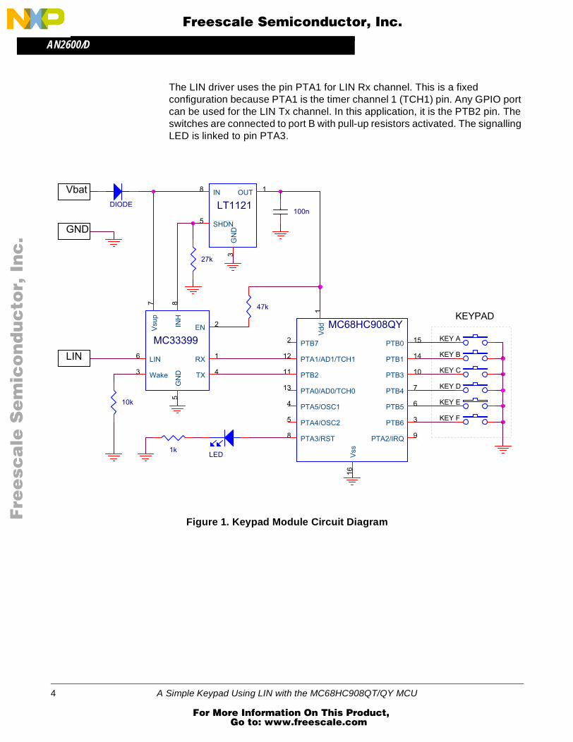
The target MCU for the keypad module is the MC68HC908QY/QT. This MCU includes an internal oscillator, a power-on reset module, and selectable pullups on all ports. Therefore, a power supply with a bypass capacitor is the only thing necessary to connect to the MCU. The circuit diagram of this keyboard application is shown in Figure 1.
Other than the MCU itself, two chips are required to implement a simple LIN node. These are the LIN interface (in this case the Motorola MC33399) and a 5-V regulator. These chips could possibly be replaced by a single chip, for example the Motorola MC33689 LIN SBC (system basis chip). As a regulator, a 3-pin 7805 or an 8-pin LT1121 chip is used. This configuration has the capability of forcing the LIN device into a low-power sleep mode under the control of the MCU. This option is not used in this application. The MC33399 includes a 30-kΩ LIN pullup, so this does not need to be included on the PCB.
A Simple Keypad Using LIN with the MC68HC908QT/QY MCU 3
For More Information On This Product, Go to: www.freescale.com
AN2600/D
F
ree
sca
le S
em
ico
nd
uc
tor,
I
Freescale Semiconductor, Inc.n
c..
.
The LIN driver uses the pin PTA1 for LIN Rx channel. This is a fixed configuration because PTA1 is the timer channel 1 (TCH1) pin. Any GPIO port can be used for the LIN Tx channel. In this application, it is the PTB2 pin. The switches are connected to port B with pull-up resistors activated. The signalling LED is linked to pin PTA3.
Figure 1. Keypad Module Circuit Diagram
KEYPAD
Vbat
LIN
GND
KEY A
KEY B
KEY C
KEY D
KEY E
KEY F
MC68HC908QY
Vss
16
Vdd
1
PTB72
PTB6 3
PTA5/OSC14
PTA4/OSC25
PTB5 6
PTB4 7
PTA3/RST8 PTA2/IRQ 9
PTB3 10PTB211
PTA1/AD1/TCH112
PTA0/AD0/TCH013
PTB1 14
PTB0 15
DIODE
MC33399
LIN6
Wake3
Vsup
7
EN 2
TX 4
RX 1
INH
8G
ND
5
LT1121
IN8 OUT 1
GN
D3
SHDN5
47k
100n
1k
27k
10k
LED
4 A Simple Keypad Using LIN with the MC68HC908QT/QY MCU
For More Information On This Product, Go to: www.freescale.com
AN2600/DApplication Software
F
ree
sca
le S
em
ico
nd
uc
tor,
I
Freescale Semiconductor, Inc.n
c..
.
Application Software
The project software must serve the application keypad and share the keypad status via the LIN network. Therefore, it is necessary to define a specific ID (six-bits-long) for each message, which will be used for reception or transmission. The message ID is written in a hexadecimal format with the parity bits included. According to the LIN specification, the data field can be 1 to 8 bytes long (for LIN 1.2 and newer).
Because the application is for demo purposes only, it uses two LIN messages (both 2-bytes long), one for reception and the second for transmission. In the transmitted message, the first data byte corresponds to the buttons currently pressed, and the second byte carries information about buttons pressed down for longer than three seconds.
The slave also receives a respective message from the master. The LSB of the first data byte is thus used to control the LED of the keypad.
This application is based on the Motorola LIN QY/QT driver software described in AN2599/D: Generic LIN Driver for MC68HC908QY4. This driver establishes all LIN connectivity related tasks within the project, and it is available free of charge from the Motorola LIN website: www.motorola.com/semiconductors/LIN.
An interface between the LIN driver and the application is done by using two API functions:
• LIN_PutMsg() — loads data into message buffer to be sent to the master
• LIN_GetMsg() —used for receiving data from the master.
For more details about these two functions as well as the driver implementation, please see AN2599/D.
Table 1. Application Messages
ID ID with Parity Sender Length
[Bytes]Message
Data
0x1A 0x1A Master 2 See Table 3
0x1B 0x5B Keypad slave 2 See Table 2
A Simple Keypad Using LIN with the MC68HC908QT/QY MCU 5
For More Information On This Product, Go to: www.freescale.com
AN2600/D
F
ree
sca
le S
em
ico
nd
uc
tor,
I
Freescale Semiconductor, Inc.n
c..
.
Main Programming Loop
In the main loop of the application (depicted in Figure 2), Read_Button() and LIN_Msg() functions are called.
Figure 2. Main Loop Flowchart
The first function (Read_Button()) reads the port B values (where the switches are connected). They are compared to the previous values. If both values are equal, the counter keypadcount is used for the debouncing delay and also to decide if the same state has been present for long enough. For a short key press, the state of the keypad is saved to data1 variable (keypad status 1), while for a long key press, the keypad value is latched and stored in data2 (keypad status 2). The mapping of the keypads within the status variables is shown in Table 2.
CLEAR OVERFLOW FLAG
START main()
INITIALIZATION OF THE
TIMEROVERFLOW?
N
READ KEYPAD STATUS
Read_Button()
MCU PERIPHERALS
INIT LIN DRIVER
LIN_Init()
LIN Rx and Tx
LIN_Msg()
Y
6 A Simple Keypad Using LIN with the MC68HC908QT/QY MCU
For More Information On This Product, Go to: www.freescale.com
AN2600/DApplication Software
F
ree
sca
le S
em
ico
nd
uc
tor,
I
Freescale Semiconductor, Inc.n
c..
.
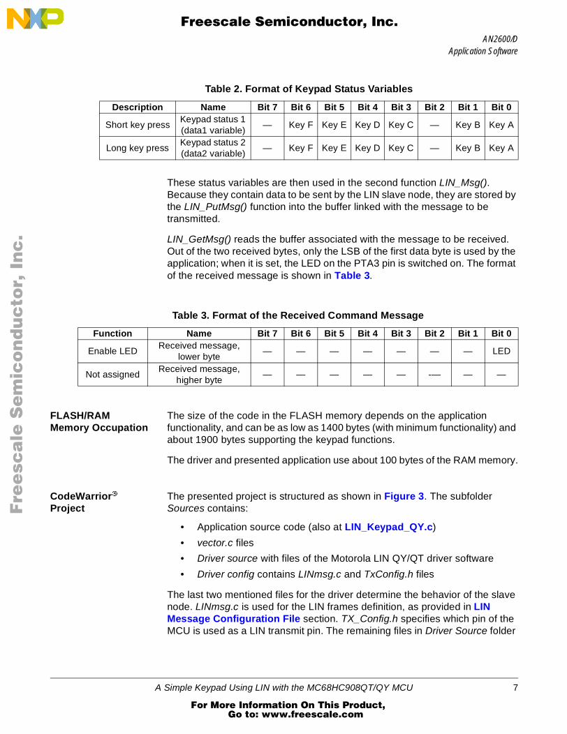
These status variables are then used in the second function LIN_Msg(). Because they contain data to be sent by the LIN slave node, they are stored by the LIN_PutMsg() function into the buffer linked with the message to be transmitted.
LIN_GetMsg() reads the buffer associated with the message to be received. Out of the two received bytes, only the LSB of the first data byte is used by the application; when it is set, the LED on the PTA3 pin is switched on. The format of the received message is shown in Table 3.
FLASH/RAM Memory Occupation
The size of the code in the FLASH memory depends on the application functionality, and can be as low as 1400 bytes (with minimum functionality) and about 1900 bytes supporting the keypad functions.
The driver and presented application use about 100 bytes of the RAM memory.
CodeWarrior Project
The presented project is structured as shown in Figure 3. The subfolder Sources contains:
• Application source code (also at LIN_Keypad_QY.c)
• vector.c files
• Driver source with files of the Motorola LIN QY/QT driver software
• Driver config contains LINmsg.c and TxConfig.h files
The last two mentioned files for the driver determine the behavior of the slave node. LINmsg.c is used for the LIN frames definition, as provided in LIN Message Configuration File section. TX_Config.h specifies which pin of the MCU is used as a LIN transmit pin. The remaining files in Driver Source folder
Table 2. Format of Keypad Status Variables
Description Name Bit 7 Bit 6 Bit 5 Bit 4 Bit 3 Bit 2 Bit 1 Bit 0
Short key pressKeypad status 1 (data1 variable)
— Key F Key E Key D Key C — Key B Key A
Long key pressKeypad status 2 (data2 variable)
— Key F Key E Key D Key C — Key B Key A
Table 3. Format of the Received Command Message
Function Name Bit 7 Bit 6 Bit 5 Bit 4 Bit 3 Bit 2 Bit 1 Bit 0
Enable LEDReceived message,
lower byte— — — — — — — LED
Not assignedReceived message,
higher byte— — — — — -— — —
A Simple Keypad Using LIN with the MC68HC908QT/QY MCU 7
For More Information On This Product, Go to: www.freescale.com
AN2600/D
F
ree
sca
le S
em
ico
nd
uc
tor,
I
Freescale Semiconductor, Inc.n
c..
.
contain the LIN driver implementation code, which should not normally be modified by the user.
The subfolder Prm contains the project parameter files (.prm), to define the ROM/RAM memory locations of the MCU.
In folders Startup Code and Libs are the header/implementation files and the necessary libraries — Start08.c, MC68HC908QY4.c, MC68HC908QY4.h and ansi.lib.
Figure 3. CodeWarrior Project Tree
LIN Message Configuration File
The LIN message frames used in the application are defined in the file called LINmsg.c. This is where specific IDs must be defined by the user for each application message. This file also contains information that indicates whether the message is designated for reception or for transmission.
The message ID is written in hexadecimal format with the parity bits included. The data field can be 1 to 8 bytes long. For this application, two message IDs are used, as shown in Table 1.
• The message ID equal to 0x1A (0x1A with the parity bits included) is used for reception.
• The message ID 0x1B (0x5B with the parity) is used for transmission.
8 A Simple Keypad Using LIN with the MC68HC908QT/QY MCU
For More Information On This Product, Go to: www.freescale.com
AN2600/DApplication Software
F
ree
sca
le S
em
ico
nd
uc
tor,
I
Freescale Semiconductor, Inc.n
c..
.
A list of all the operations necessary to setup the LINmsg.c file is presented here:
1. Create a message buffer for the frame data field of each application message.
U8 volatile Message0x1A[2]; // ID 0x1A = 0x1A with parityU8 volatile Message0x5B[2]; // ID 0x1B = 0x5B with parity
2. Define a pointer array MessagePointerTbl[] containing pointers to all message buffers of the application.
3. Create an identifier table (array) IdTbl[] containing all IDs relevant to this node. Note that it must be set up in the same order as in the case of MessagePointerTbl[] and MessageCountTbl[]. Furthermore, message IDs must have parity bits included.
U8 const near IdTbl[] = 0x1A, 0x5B;
4. Finally, it is necessary to define an array variable MessageCountTbl[]. It is a table which defines (for each existing message) a length of the frame data and the checksum fields. It also indicates whether the specific message should be sent or received. The least significant half-byte of each entry denotes the length of the data and checksum fields (length of the checksum field is equal to 1), and the most significant half-byte is equal to 1 for message reception and 0 for transmission. In addition, it could also be equal to 0xF (ignore), which means that the message is ignored unless it has been updated since it was last read/written.
U8 const near MessageCountTbl[] = 0x13, 0x03;
Project Creation This section is a brief description of how to create a new project based on the Motorola LIN QY/QT driver software. For more detail, see AN2599/D.
1. Create a new project in Metrowerks CodeWarrior development system.
2. Copy the Motorola LIN QY/QT driver software into the folder structure of the project (for example into the folders lin_src and lin_inc). The driver consists of LINapi.c, LINdriver.c, LINdriver.h, LINmsg.c, and Tx_Config.h files.
3. Add the Motorola LIN QY/QT driver software into the CodeWarrior project tree (for example into the folders Sources\Driver source and Sources\Driver config).
4. In the application source file (e.g., LIN_Keypad_QY.c), include the LIN driver with: #include "LINdriver.h"
5. Define the messages in the LINmsg.c file as described in LIN Message Configuration File.
A Simple Keypad Using LIN with the MC68HC908QT/QY MCU 9
For More Information On This Product, Go to: www.freescale.com
AN2600/D
F
ree
sca
le S
em
ico
nd
uc
tor,
I
Freescale Semiconductor, Inc.n
c..
.
6. Define the transmit pin of the LIN node in the Tx_Config.h file; default is pin 2 of port B (PTB2).
7. Update the vectors of the project in vector.c file. Specifically, it is necessary to define interrupt service routine (ISR) TimA1ISR() as a VECTOR 5 (0xFFF4).
NOTE: The driver uses only timer channel 1, but usage of the timer modulus counter is prohibited because the driver assumes that the overflow value of the timer is set to 0xFFFF. No ISR is allowed other than the one used by the LIN driver during communication. The reason for this is that both the Tx and Rx pins are software driven and must have a predictable latency for the ISR response.
NOTE: The use of the LDA/modify/STA sequence for the control of port B in this interrupt-driven bit-banged driver is strongly discouraged because one pin of this port (PTB2) is used as a Tx pin of the LIN driver. If the level of this Tx pin is changed by an interrupt occurring during the sequence, the wrong level will be restored. The solution is to use only BSET and BCLR instructions when writing to port B.
NOTE: For maximum benefit, please see the Application Source Code.
CPU Usage
This section provides estimated values of CPU usage during the LIN communication. The MCU uses some of its power when executing the LIN reception/transmission functions of the LIN driver. The demand on the CPU time will depend linearly on the baud rate of the LIN network and the bus frequency of the MCU.
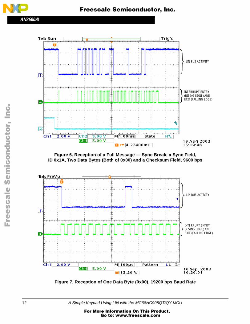
To provide these estimates, the following measurements were taken. Because all LIN driver communication activities are executed within the ISR of timer A channel 1 [TimA1ISR()], it is possible to use one unused pin of the MCU, set this pin high on the interrupt entry, and clear it to low just before the rti instruction of the ISR.
Several scope screen captures were created. These measurements indicate that an average CPU usage during the LIN communication measured over one received byte is approximately 30% at a 9600 bps baud rate, and approximately 53% at a 19,200 bps baud rate. And over one relevant frame (two data bytes long), CPU usage is approximately 24% (for a 9600 bps baud rate) and 41% (for a 19,200 bps baud rate).
Figure 4, Figure 5, and Figure 6 were measured at a 9600 bps baud rate. Figure 7, Figure 8, and Figure 9 were measured at a 19,200 bps baud rate.
Figure 4, Figure 5, Figure 7, and Figure 8 show a reception of one data byte. Figure 6 and Figure 9 display reception of a full message.
10 A Simple Keypad Using LIN with the MC68HC908QT/QY MCU
For More Information On This Product, Go to: www.freescale.com
AN2600/DCPU Usage
F
ree
sca
le S
em
ico
nd
uc
tor,
I
Freescale Semiconductor, Inc.n
c..
.
Figure 4. Reception of One Data Byte (0x00), 9600 bps Baud Rate
Figure 5. Reception of One Data Byte (0x00) — Detail, 9600 bps Baud Rate
A Simple Keypad Using LIN with the MC68HC908QT/QY MCU 13
For More Information On This Product, Go to: www.freescale.com
AN2600/D
F
ree
sca
le S
em
ico
nd
uc
tor,
I
Freescale Semiconductor, Inc.n
c..
.
References
1. MC68HC908QY/QT Data Sheet,Motorola document number: MC68HC908QY4/D
2. LIN Specification Package, Revision 1.3, 12 December 2002
3. Generic LIN Driver for MC68HC908QY4,Motorola document number: AN2599/D
4. LINkits LIN Evaluation Boards,Motorola document number: AN2573/D
5. Car Door Keypad Using LIN,Motorola document number: AN2205/D
Acronyms
LIN Local interconnect network
CAN Controller area network
MOST Media-oriented system transport
GPIO Genera-purpose input/output
PCB Printed circuit board
ID Identifier
A/D Analog-to-digital
MCU Microcontroller unit
LSB Least significant bit
ISR Interrupt service routine
14 A Simple Keypad Using LIN with the MC68HC908QT/QY MCU
For More Information On This Product, Go to: www.freescale.com
AN2600/DApplication Source Code
F
ree
sca
le S
em
ico
nd
uc
tor,
I
Freescale Semiconductor, Inc.n
c..
.
Application Source Code
LIN_Keypad_QY.c
/******************************************************************************* (c) MOTOROLA Inc. 2003 all rights reserved. ** ** ** LIN keypad slave node for MC68HC908QY4 ** ====================================== ** ** Originator: David Svrcek ** Date: 11th September 2003 ** $Version: 1.1.4.0$ ** Function: Slave keypad receives a 2-byte message and supplies ** a 2-byte response. The MCU sends in the first byte ** the value corresponding to the pressed buttons, and ** in the second byte the value corresponding with longer ** pressed buttons (those pressed down for longer ** than 3 seconds). If bit 0 in the first receiving byte ** is set, then the LED on pin PTA3 is enabled. ** All the other bits are zero. ** *******************************************************************************/
/******************************************************************************* ** Includes, defines, globals and function prototypes ** *******************************************************************************/
#include “MC68HC908QY4.h”#include “LINdriver.h”#include “LIN_Keypad_QY.h” #define KEEPCOUNT 145 /* 20.5ms x (145+1) = 3s */#define BUTTONS (~PTB) & 0x7B /* define buttons on pins */#define ID_RECEIVE 0x1A /* ID for receiving */#define ID_SEND 0x5B /* ID for sending */#define LED_STATUS 0x01 /* bit 0 in data st. reg.1 */#define LED_SET PTA |= 0x08; /* set LED on PTA3 pin */#define LED_CLEAR PTA &= 0xF7; /* clear LED on PTA3 pin */#define EVER (;;) /* forever loop */ #pragma DATA_SEG SHORT _DATA_ZEROPAGE
unsigned char data1 = 0; /* keypad status 1 */unsigned char data2 = 0; /* keypad status 2 */
unsigned char MsgSent [2]; /* transmitted data */
A Simple Keypad Using LIN with the MC68HC908QT/QY MCU 15
For More Information On This Product, Go to: www.freescale.com
AN2600/D
F
ree
sca
le S
em
ico
nd
uc
tor,
I
Freescale Semiconductor, Inc.n
c..
.
unsigned char MsgRcvd [2]; /* received data */
#pragma DATA_SEG DEFAULT
/******************************************************************************* ** Function name: Main ** Originator: D.Svrcek ** Date: 8th August 2003 ** Function: The microprocessor is configured and initialized. ** In the main never ending loop two functions are called, ** ‘Read-Button’ and ‘LIN_Msg’. ** *******************************************************************************/
DDRB = 0x04; /* enable port B outputs */ /* KEYS: B0,B1,B3,B4,B5,B6 */ /* TX: PTB2 */ PTBPUE = 0x7B; /* enable pullup on port B */ TSC = 0x00; /* timer prescaler/1,start */
OSCTRIM = 0; /* trim to max. frequency */
asm cli; /* enable interrupts */
LIN_Init(); /* initialise LIN drivers */ PTA = 0x00; /* clear port A */
for EVER if (TSC_TOF) /* is overflow flag set? */ TSC_TOF = 0; /* yes, clear it */ Read_Button (); /* read buttons on PTB */ LIN_Msg (); /* send and receive LIN msg*/
16 A Simple Keypad Using LIN with the MC68HC908QT/QY MCU
For More Information On This Product, Go to: www.freescale.com
AN2600/DApplication Source Code
F
ree
sca
le S
em
ico
nd
uc
tor,
I
Freescale Semiconductor, Inc.n
c..
.
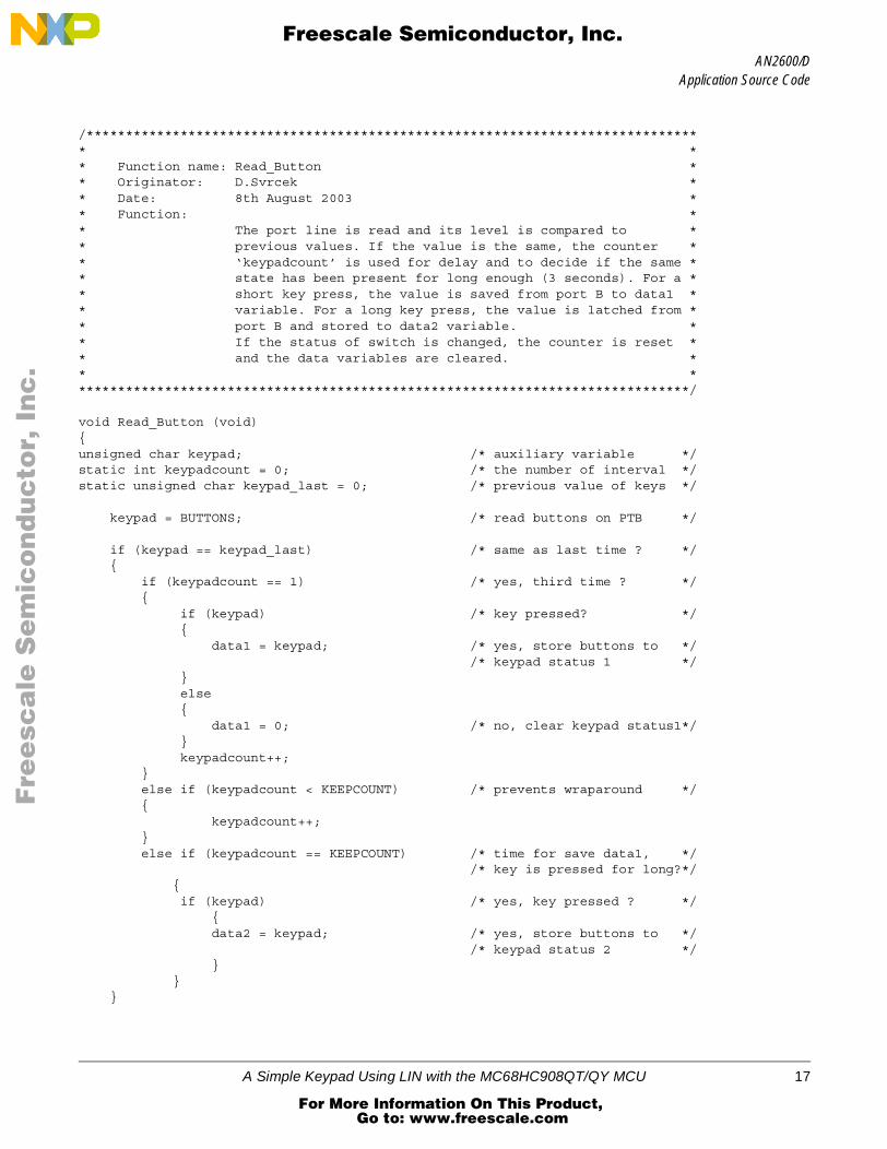
/******************************************************************************* ** Function name: Read_Button ** Originator: D.Svrcek ** Date: 8th August 2003 ** Function: ** The port line is read and its level is compared to ** previous values. If the value is the same, the counter ** ‘keypadcount’ is used for delay and to decide if the same ** state has been present for long enough (3 seconds). For a ** short key press, the value is saved from port B to data1 ** variable. For a long key press, the value is latched from ** port B and stored to data2 variable. ** If the status of switch is changed, the counter is reset ** and the data variables are cleared. ** *******************************************************************************/
void Read_Button (void)unsigned char keypad; /* auxiliary variable */static int keypadcount = 0; /* the number of interval */static unsigned char keypad_last = 0; /* previous value of keys */
keypad = BUTTONS; /* read buttons on PTB */ if (keypad == keypad_last) /* same as last time ? */ if (keypadcount == 1) /* yes, third time ? */ if (keypad) /* key pressed? */ data1 = keypad; /* yes, store buttons to */ /* keypad status 1 */ else data1 = 0; /* no, clear keypad status1*/ keypadcount++; else if (keypadcount < KEEPCOUNT) /* prevents wraparound */ keypadcount++; else if (keypadcount == KEEPCOUNT) /* time for save data1, */ /* key is pressed for long?*/
if (keypad) /* yes, key pressed ? */
data2 = keypad; /* yes, store buttons to */ /* keypad status 2 */
A Simple Keypad Using LIN with the MC68HC908QT/QY MCU 17
For More Information On This Product, Go to: www.freescale.com
AN2600/D
F
ree
sca
le S
em
ico
nd
uc
tor,
I
Freescale Semiconductor, Inc.n
c..
.
else keypadcount = 0; /* no, different, so reset */ keypad_last = keypad; /* count and save status */ data1 = 0; /* clear keypad status 1 */ data2 = 0; /* clear keypad status 2 */
/******************************************************************************* ** Function name: LIN_Msg ** Originator: D.Svrcek ** Date: 8th August 2003 ** Function: The keypad status variables are saved to the buffer used ** by the drivers for sending. The function ‘LIN_GetMsg’ ** receive two bytes, if bit 0 in the first byte is set, ** then the LED on the PTA3 pin is enabled. ** *******************************************************************************/
void LIN_Msg (void) MsgSent[0] = data1; MsgSent[1] = data2; LIN_GetMsg (ID_RECEIVE, MsgRcvd); /* read LIN message */ if (MsgRcvd[0] & LED_STATUS) /* if first bit is set */ /* enable LED */ LED_SET; /* yes, set LED */ else LED_CLEAR; /* no, clear LED */
LIN_PutMsg (ID_SEND, MsgSent); /* LIN response to 0x1B */ /* 0x1B with parity = 0x5B */
/******************************************************************************* Function: LIN_Command ** Description: User call-back. Called by the driver after transmission or ** reception of the Master Request Command Frame (ID: 0x3C). *******************************************************************************/ void LIN_Command() for EVER
18 A Simple Keypad Using LIN with the MC68HC908QT/QY MCU
For More Information On This Product, Go to: www.freescale.com
AN2600/DApplication Source Code
F
ree
sca
le S
em
ico
nd
uc
tor,
I
Freescale Semiconductor, Inc.n
c..
.
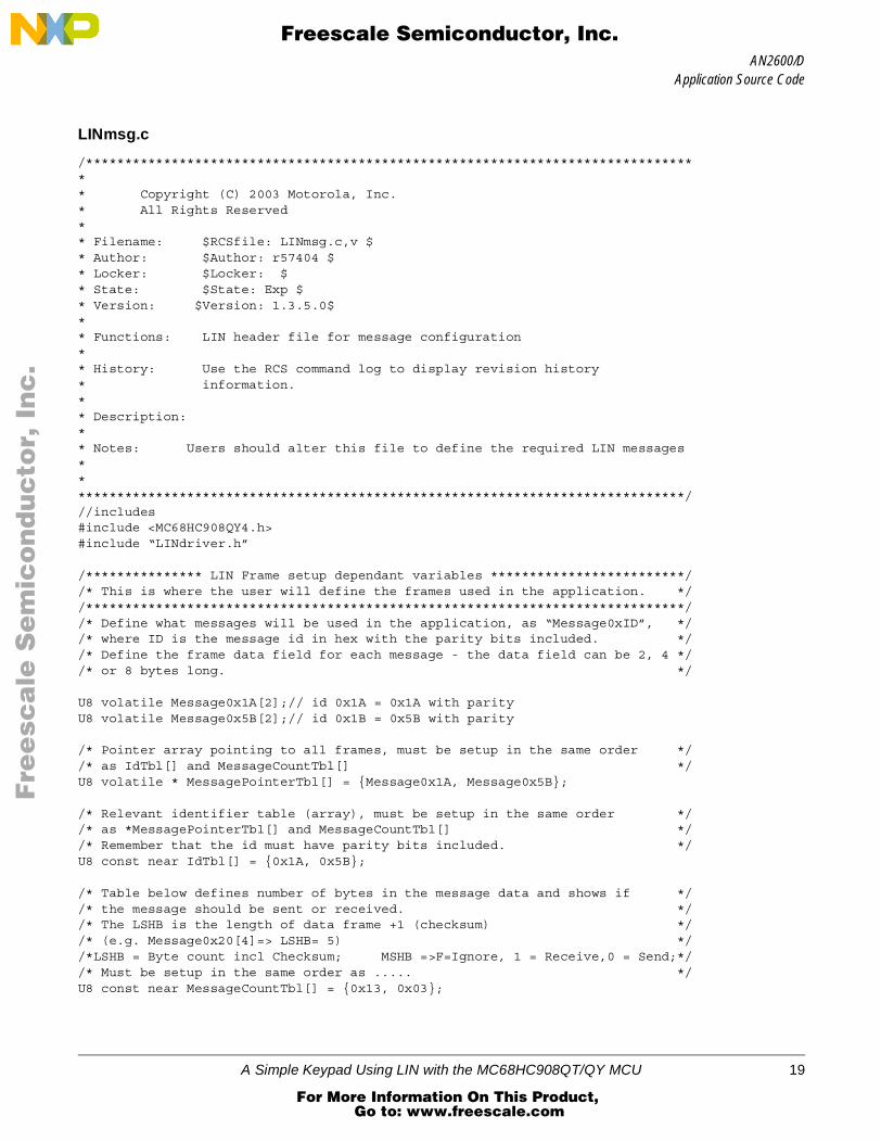
LINmsg.c
/******************************************************************************** Copyright (C) 2003 Motorola, Inc.* All Rights Reserved** Filename: $RCSfile: LINmsg.c,v $* Author: $Author: r57404 $* Locker: $Locker: $* State: $State: Exp $* Version: $Version: 1.3.5.0$** Functions: LIN header file for message configuration** History: Use the RCS command log to display revision history* information.** Description: ** Notes: Users should alter this file to define the required LIN messages********************************************************************************///includes#include <MC68HC908QY4.h> #include “LINdriver.h”
/*************** LIN Frame setup dependant variables *************************//* This is where the user will define the frames used in the application. *//*****************************************************************************//* Define what messages will be used in the application, as “Message0xID”, *//* where ID is the message id in hex with the parity bits included. *//* Define the frame data field for each message - the data field can be 2, 4 *//* or 8 bytes long. */
U8 volatile Message0x1A[2];// id 0x1A = 0x1A with parityU8 volatile Message0x5B[2];// id 0x1B = 0x5B with parity
/* Pointer array pointing to all frames, must be setup in the same order *//* as IdTbl[] and MessageCountTbl[] */U8 volatile * MessagePointerTbl[] = Message0x1A, Message0x5B;
/* Relevant identifier table (array), must be setup in the same order *//* as *MessagePointerTbl[] and MessageCountTbl[] *//* Remember that the id must have parity bits included. */U8 const near IdTbl[] = 0x1A, 0x5B;
/* Table below defines number of bytes in the message data and shows if *//* the message should be sent or received. *//* The LSHB is the length of data frame +1 (checksum) *//* (e.g. Message0x20[4]=> LSHB= 5) *//*LSHB = Byte count incl Checksum; MSHB =>F=Ignore, 1 = Receive,0 = Send;*/ /* Must be setup in the same order as ..... */U8 const near MessageCountTbl[] = 0x13, 0x03;
A Simple Keypad Using LIN with the MC68HC908QT/QY MCU 19
For More Information On This Product, Go to: www.freescale.com
AN2600/D
F
ree
sca
le S
em
ico
nd
uc
tor,
I
Freescale Semiconductor, Inc.n
c..
.
/* LIN_LIST_SIZE is the number of Id:s in the IdTbl[] */#define LIN_LIST_SIZE (( sizeof(IdTbl)) / sizeof( IdTbl[0] ) )
/* No_of_Ids is the number of Ids in IdTbl[] */U8 const No_of_Ids = LIN_LIST_SIZE;
/* to store message status, e.g. LIN_MSG_NODATA or LIN_MSG_UPDATED */U8 volatile LinMsgStatus[LIN_LIST_SIZE];
/**************** END LIN Frame setup dependant variables. *******************/
20 A Simple Keypad Using LIN with the MC68HC908QT/QY MCU
For More Information On This Product, Go to: www.freescale.com
AN2600/D
F
ree
sca
le S
em
ico
nd
uc
tor,
I
Freescale Semiconductor, Inc.n
c..
.
A Simple Keypad Using LIN with the MC68HC908QT/QY MCU 21
For More Information On This Product, Go to: www.freescale.com
AN2600/D
22 A Simple Keypad Using LIN with the MC68HC908QT/QY MCU
Fre
esc
ale
Se
mic
on
du
cto
r, I
Freescale Semiconductor, Inc.
For More Information On This Product, Go to: www.freescale.com
nc
...
AN2600/D
A Simple Keypad Using LIN with the MC68HC908QT/QY MCU 23
Fre
esc
ale
Se
mic
on
du
cto
r, I
Freescale Semiconductor, Inc.
For More Information On This Product, Go to: www.freescale.com
nc
...
AN2600/D
Fre
esc
ale
Se
mic
on
du
cto
r, I
Freescale Semiconductor, Inc.
For More Information On This Product, Go to: www.freescale.com