Page 1
HERON Vol. 53 (2008) No. 4
Full-scale testing of infilled steel frames with precast concrete panels provided with a window opening P.A. Teeuwen, C.S. Kleinman, H.H. Snijder, H. Hofmeyer
Eindhoven University of Technology, Eindhoven, The Netherlands
As an alternative to conventional structures for tall buildings, a hybrid lateral load resisting
building system has been designed, enabling the assembly of tall buildings directly from
truck. It consists of steel frames with discretely connected precast concrete infill panels
provided with a window opening. Besides the stiffening and strengthening effect of the infill
panels on the frame structure, economical benefits may be derived from saving costs on
materials and labour, and from reducing construction times. Design rules are needed to
facilitate the application of this lateral load resisting structure for the construction of tall
buildings. In order to come to design rules, the infilled frame structure is currently subject to
experimental, numerical, and theoretical analyses. This article concerns the experimental part
of the research.
To provide insight into the composite behaviour between steel frames and discretely
connected precast concrete infill panels, and at the same time, provide a basis for
development of numerical models, the structure was subject to experimental research. Ten
full-scale tests on one-storey, one-bay, 3 by 3 m infilled frame structures were performed. The
steel frame consists of HE180M sections in S235 which are simply connected, and is subjected
to lateral load. The precast concrete panels provided with a window opening are made of
C45/55 and have a thickness of 200 mm. To investigate the effect of the size and position of a
window opening, five different opening geometries were tested. The precast concrete panel is
connected to the steel frame by discrete steel-to-concrete connections that are realized by
structural bolts on the column and beam in every corner of the steel frame. The infilled
frames are designed to fail by a bolt failure mechanism.
The experiments show that discretely connected precast concrete panels provided with a
window opening can significantly improve the performance of steel frames. The observed
lateral stiffnesses of the infilled frames range between 4 and 13 times that of the bare frames.
All infilled frame structures were able to support a lateral load of over 583 kN. For four panel
Page 2
196
geometries, the discrete connections were governing the strength of the structure while for
the test with the largest panel opening, the infill panel failed first.
Key words: Infilled frame, steel, precast concrete, lateral resistance, experiments, full-scale
1 Introduction
Construction time, more than ever, is a cost-crucial factor. Reducing construction time
means saving money both directly and indirectly for example due to reduced nuisance to
the surroundings of the building site. Reduction of construction time can be achieved by
many means, for example the use of prefabricated elements, dry connections or smarter
construction procedures. Meeting the demand of reduced construction time, an integrated
lateral load resisting building system has been designed for the construction of tall
buildings at Eindhoven University of Technology. It is an integrated building system
consisting of infilled steel frames with discretely connected precast concrete infill panels,
enabling the assembly of tall buildings directly from truck. Besides the stiffening and
strengthening effect of the infill panels on the frame structure, economical benefits may be
derived from saving costs on materials and labour, and from reducing construction time.
The use of precast concrete panels in steel frames is a new area of application in infilled
frames, although the phenomenon ‘infilled frame’ has a long history. Since the early fifties
extensive investigations have been done into the structural behaviour of framed structures
with masonry and cast-in-place concrete infills (Holmes, M (1961), Ng’andu, B.M. (2006)).
When connectors or strong bonding at the interfaces between the frame and the infill panel
are absent as for example with masonry infill, the structures are in the literature known as
non-integral infilled frames (Figure 1a). When these are subjected to lateral loading, a large
portion of the load is taken by the infill panel at its loaded corner. The provision of strong
bonding or connectors at the interface enables the two components (frame and panel) to act
compositely. These infilled frames are known as fully-integral infilled frames (Figure 1b).
Part of the shearing load is transmitted from the frame to the infill panel through the
connectors. Because of the stiffening and strengthening effect of infill panels on frames,
the sway of the structure under lateral loading is considerably reduced. Even with window
openings in the infill panels, the lateral stiffness of a framed structure can significantly be
improved (Mallick, D.V. and Garg, R.P. (1971), Liauw, T.C (1972)).
Page 3
197
Preceding research (Tang, R.B. et al. (2000), Hoenderkamp, J.C.D et al. (2005), Teeuwen,
P.A. et al. (2006)) has shown that precast concrete infill panels may be able to achieve at
least similar improvements in structural performance as masonry and cast-in-place
concrete infills. Infilled frames with discrete connections between frame and panel are
denoted as semi-integral infilled frames (Figure 1c). By completely different structural
behaviour due to application of discrete steel-to-concrete connections, existing theories for
frames with masonry and cast-in-place concrete infills (Liauw, T.C (1972), Stafford-Smith,
B. (1966), Liauw, T.C. and Kwan, K.H. (1983)) are not suitable for analysing infilled steel
frames with precast concrete panels. New design rules are needed to facilitate the
application of this lateral load resisting system for the construction of (tall) buildings. This
research project aims at developing these design rules. In order to come to design rules, the
infilled frame structure is currently subject to experimental, numerical, and theoretical
analyses. This article describes the experimental part of the research that was carried out to
provide insight into the structural behaviour of the structure, and discusses the results.
F F F
(a) Non-integral (b) Fully-integral (c) Semi-integral
Figure 1: Classification of infilled frames
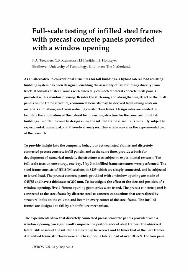
2 Discrete interface connection
A discrete steel-to-concrete connection has been developed, enabling steel frames and
precast concrete panels to act compositely when subject to lateral loading. It is realized by
structural bolts on the column and beam in every corner of the steel frame, confining the
precast concrete infill panel within the steel frame (Figure 2) leaving a (50 mm) gap
between steel and concrete along the complete panel circumference. The connection is a
dry connection which typically will function immediately after assembly. Besides, the
connections are able to adopt tolerances and enable exact positioning of the panels in both
horizontal and vertical direction.
Page 4
198
Structural bolt 8.8M24Angle member cast in concrete
150x150x15 mm
HE180M Precast concrete panel
Steel frame
High-strength steel cap
Precast concrete panel
HE180MH
E180
M
HE1
80M
t=15
100
t=15
5050
75
75
50
Discrete steel-concrete connection
Figure 2: Infilled steel frame with precast concrete infill panel
When the infilled frame is loaded laterally, the lateral load is transferred from the frame to
the panel through the bolts which act in compression only. To introduce the forces into the
infill panel, angle members are cast at every corner of the panel. To prevent high stress
concentrations in the angle members directly under the compression bolts, high-strength
steel caps are applied there. The infilled frame structure is designed to fail by a bolt failure
mechanism. Failure of the bolts will not directly result in failure of the entire structure, as
force transmission will still occur in the loaded corners of the frame by contact pressure
between frame and panel (fail safe concept). Moreover, bolts can easily be replaced while
the steel structure and the concrete panel remain undamaged. The anticipated failure mode
is shearing of the bolt through the nut. To provide insight into this failure behaviour,
preceding investigations into the structural behaviour of the different components of the
steel-concrete connection were carried out (Teeuwen et al., 2007). This investigation
showed that the bolts subject to axial compressive loading fail by thread stripping failure
and not by yielding of the bolt like for bolts subject to tensile loading.
3 Full-scale experiments
3.1 Objectives of experiments
In order to provide insight into the composite behaviour between steel frames and
discretely connected precast concrete infill panels provided with a window opening, full-
scale experiments were conducted. The main objectives of the full-scale experiments were
to observe the general behaviour of the structures in terms of stiffness, strength and
Page 5
199
ductility. At the same time, the influence of the chosen parameter, being the size and
position of the window opening was investigated. Besides, the results of these experiments
were used to validate a finite element model that will be used to carry out parametric
studies.
3.2 Test setup
3.2.1 Test rig
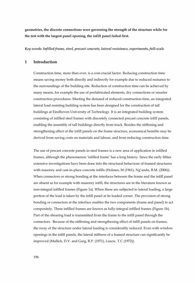
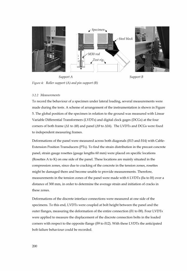
A specifically designed test rig was used to perform the full scale tests on one-storey, one-
bay, 3 by 3 m infilled frame structures (Figure 3). This test rig is composed of two rigid
triangular frames, constructed of HE300B members. These two triangular frames are linked
through rigid steel members at their corners. A specimen can be positioned between the
two triangular frames and is supported on two different supports (Figure 4). At the side of
the jack, the lower corner of the specimen is fixed in vertical direction to the test rig by four
steel M30 rods. This support is intended to act as a roller support with a restrained
displacement in vertical direction only (support A). At the opposite lower corner, the
specimen is supported in a heavy steel block which restrains the specimen from both
horizontal and vertical displacement. This support is supposed to act as a pin support
(support B). A specimen can be loaded laterally by a jack that is coupled to the top corner
of the triangular frames by stiff steel plates, acting at the height of the top beam centre.
This jack has a stroke of 200 mm and is able to provide a maximum load of 2 MN.
Figure 3: Schematic view and picture of test rig with a mounted specimen
Specimen Jack
Test rig
Sup. A Sup. B
3 m
3 m
Page 6
200
Support A Support B
Figure 4: Roller support (A) and pin support (B)
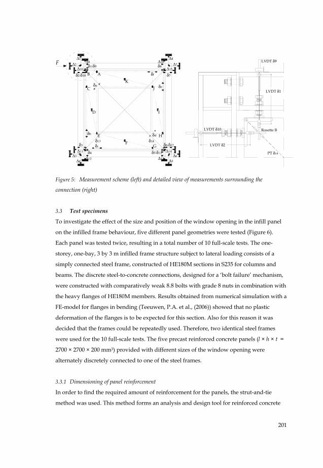
3.2.2 Measurements
To record the behaviour of a specimen under lateral loading, several measurements were
made during the tests. A scheme of arrangement of the instrumentation is shown in Figure
5. The global position of the specimen in relation to the ground was measured with Linear
Variable Differential Transformers (LVDTs) and digital clock gages (DCGs) at the four
corners of both frame (Δ1 to Δ8) and panel (Δ9 to Δ16). The LVDTs and DCGs were fixed
to independent measuring frames.
Deformations of the panel were measured across both diagonals (δ13 and δ14) with Cable-
Extension Position Transducers (PTs). To find the strain distribution in the precast concrete
panel, strain gauge rosettes (gauge lengths 60 mm) were placed on specific locations
(Rosettes A to K) on one side of the panel. These locations are mainly situated in the
compression zones, since due to cracking of the concrete in the tension zones, rosettes
might be damaged there and become unable to provide measurements. Therefore,
measurements in the tension zones of the panel were made with 6 LVDTs (δa to δf) over a
distance of 300 mm, in order to determine the average strain and initiation of cracks in
these zones.
Deformations of the discrete interface connections were measured at one side of the
specimens. To this end, LVDTs were coupled at bolt height between the panel and the
outer flanges, measuring the deformation of the entire connection (δ1 to δ8). Four LVDTs
were applied to measure the displacement of the discrete connection bolts in the loaded
corners with respect to the opposite flange (δ9 to δ12). With these LVDTs the anticipated
bolt failure behaviour could be recorded.
M30 rod
Steel block
Specimen
Test rig
Page 7
201
AB
C
D
E
F
KJ
I
H
G
Δ1
δ1/δ9 δ8
δ4 δ5/δ11
δ2/δ10 δ7
δ3 δ6/δ12
δf
δe
δc
δb δd
δa
Δ2
δ13 δ14
Δ10
Δ9
Δ15
Δ16
Δ11
Δ12
Δ14
Δ13
Δ8
Δ7
Δ4Δ3
Δ5Δ6
LVDT δ9
LVDT δ1
LVDT δ10
LVDT δ2
Rosette B
PT δ14
F
Figure 5: Measurement scheme (left) and detailed view of measurements surrounding the
connection (right)
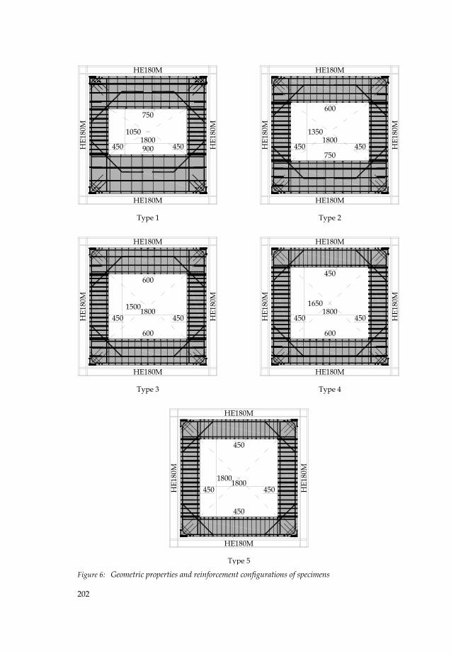
3.3 Test specimens
To investigate the effect of the size and position of the window opening in the infill panel
on the infilled frame behaviour, five different panel geometries were tested (Figure 6).
Each panel was tested twice, resulting in a total number of 10 full-scale tests. The one-
storey, one-bay, 3 by 3 m infilled frame structure subject to lateral loading consists of a
simply connected steel frame, constructed of HE180M sections in S235 for columns and
beams. The discrete steel-to-concrete connections, designed for a ‘bolt failure’ mechanism,
were constructed with comparatively weak 8.8 bolts with grade 8 nuts in combination with
the heavy flanges of HE180M members. Results obtained from numerical simulation with a
FE-model for flanges in bending (Teeuwen, P.A. et al., (2006)) showed that no plastic
deformation of the flanges is to be expected for this section. Also for this reason it was
decided that the frames could be repeatedly used. Therefore, two identical steel frames
were used for the 10 full-scale tests. The five precast reinforced concrete panels (l × h × t =
2700 × 2700 × 200 mm3) provided with different sizes of the window opening were
alternately discretely connected to one of the steel frames.
3.3.1 Dimensioning of panel reinforcement
In order to find the required amount of reinforcement for the panels, the strut-and-tie
method was used. This method forms an analysis and design tool for reinforced concrete
Page 8
202
1800450 450
450 450
450
1050 1350
1500
1800
1800
1800 1800
1800
HE180M
HE180M
HE1
80M
HE1
80M
1650
HE180M
HE180M
HE1
80M
HE1
80M
HE180M
HE180M
HE1
80M
HE1
80M
HE180M
HE180M
HE1
80M
HE1
80M
HE180M
HE180M
HE1
80M
HE1
80M
Type 1
Type 3 Type 4
Type 2
450450
450 450
450
450600
600
450
450
600
750
750
900
600
Figure 6: Geometric properties and reinforcement configurations of specimens
Page 9
203
elements in which it may be assumed that internal stresses are transferred through a truss
mechanism. The tensile ties and compressive struts serve as truss members connected by
nodes. Struts are the compression members of a strut-and-tie model and represent concrete
stress fields whose principal compressive stresses are predominantly present along the
centreline of the strut. Ties are the tension members of a strut-and-tie model and mostly
represent reinforcing steel or occasionally concrete stress fields with principal tension
predominant in the tie direction. Nodes are, analogous to joints in a truss, the places where
forces are transferred between struts and ties. As a result, these regions are subject to a
multidirectional state of stress.
To determine the required reinforcement, the panels are considered as two dimensional
plate elements (i.e. plane stress condition without variation of stress over the thickness of
the element). In the ultimate limit state, the panels are assumed to be loaded only at the
compressive corners c (Figure 7) of the confining frame, as loss of contact pressure between
infill panel and frame at the tension corners t was observed during preliminary tests
(Teeuwen et al., 2006). Due to the presence of an opening in the panel, direct support from
the load to the support by a strut under compression is impossible. Therefore the load is
transferred around the opening to the support, resulting in tensile forces in the outer edge
of the panel which have to be supported by appropriate reinforcement. Figure 7a shows
the positions of the concrete struts (dashed lines) and tensile ties (solid lines) as well as two
other concrete struts, which are necessary to maintain equilibrium.
t
ct
c t
ct
c
(a) (b)
Figure 7: Schematic representation of development of stress fields in infill panel
Page 10
204
The adopted stress field can be considered as two knee frames, pin connected to each other
in the loaded corners. These corners are, according to the adopted stress field, unable to
support bending forces. Therefore, this stress field will cause considerable deformations,
concentrated in open cracks. In order to avoid these considerable concentrated
deformations, additional reinforcement is necessary around the inner edge of the panel to
support tensile stresses there (Figure 7b).
After the truss model is generated, linear elastic truss analysis is performed to obtain the
member forces. With these found member forces, the required reinforcement (As) is
determined (As = T/fy, in which T stands for tie force and fy for yield stress). Next, the
compressive stresses in the struts and nodes at critical locations are calculated. The found
stresses are compared with the limit stresses accounting for the level of concrete
confinement, which were obtained from literature (ASCE-ACI Committee 445 on Shear
and Torsion (1998)) to verify that crushing of the compressive struts and nodes does not
occur. Finally, the members of the concrete panel were designed to resist shear. The
“standard method” of the shear design procedure that can be found in Eurocode 2 was
applied.
Based on the results of the above discussed methods, the panels were all reinforced with
longitudinal reinforcement Ø25 and stirrup reinforcement Ø8 with a concrete cover of 15
mm. Based on engineering judgment, inclined reinforcement bars (Ø25) were added at the
re-entrant corners. Angle members (150 × 150 × 15) in S235 were cast in the outer corners of
the panel. Wedge reinforcement was provided in the outer corners to prevent concrete
tensile splitting there. All applied reinforcement was FeB500. The panels were cast in a
precast concrete factory. A self-compacting concrete was applied of concrete grade C45/55.
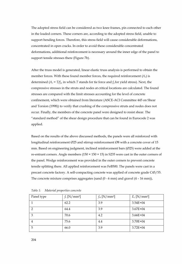
The concrete mixture comprises aggregates (sand (0 - 6 mm) and gravel (4 – 16 mm)),
Table 1: Material properties concrete
Panel type fc [N/mm2] fct [N/mm2] Ec [N/mm2]
1 62.2 3.9 3.54E+04
2 64.4 3.9 3.67E+04
3 70.6 4.2 3.66E+04
4 75.6 4.4 3.70E+04
5 66.0 3.9 3.72E+04
Page 11
205
limestone meal, Portland cement CEM I 52,5 R which develops a high early strength that is
needed for a one-day casting cycle, super plasticizer, and water (water-cement ratio =
0.45).
Standard material tests were performed to find the actual cylinder compressive strength fc,
the tensile strength fct and the Young’s modulus Ec. The results of the material tests are
presented in Table 1.
3.4 Testing procedures
In order to quantify the contribution of an infill panel to the stiffness of its confining frame
structure, the stiffness of the bare frame structure (without the infill) has to be known. For
that reason, the bare frame was tested each time before mounting the precast concrete infill
panel within the frame. Therefore, first the beams and columns were assembled. The bolts
in the beam-to-column connections were torque controlled tightened up to a specified
torque of 400 Nm, to get identical initial stiffnesses of the bare frames for all tests as best as
possible. Other conditions that might influence the coefficient of friction and so the torque
as e.g. surface conditions, corrosion and temperature, are supposed to remain unchanged
as each time the same series of bolts were used within identical climatic circumstances. The
test procedure of the bare frames involved a preliminary preload up to 20 kN to close up
initial gaps and contact tolerances between the specimen and the test rig. After the
unloading, the bare frames were loaded again up to a maximum load of 60 kN. This
maximum load was chosen such, that deformations of the frame would be in the elastic
range and therefore did not influence the infilled frame behaviour.
After the bare frame was tested, it was fixed to the horizontally positioned panel. Then, the
discrete connection bolts were placed and tightened up to a specified torque of 275 Nm,
once again to provide identical boundary conditions as good as possible for all tests. Since
the infilled-frames were assembled in horizontal position, the dead weight did not
influence the initial prestress levels in the bolts. After erecting the infilled frame structure
and thereupon installing the measurement instrumentation, it was positioned in the test
rig. The testing procedure of the infilled frames involved a preliminary preload of 50 kN
(and unloading), for the same reason as mentioned before. Next, the infilled frames were
loaded up to failure. For both bare frame and infilled frame, the load was applied
displacement controlled. For this purpose the stroke of the jack was controlled at 1
mm/min. At this rate, the duration of the tests with the infilled frames was about 1 hour.
Page 12
206
As mentioned before, all panels were tested a second time. To this end, the panel was
turned around its vertical axis of symmetry and replaced in the confining frame. By doing
this, the tension zones with cracks developed during the first test with the panel become
compression zones during the second test, causing the cracks to close. The possible effect
of the initial present cracks on the global structural behaviour was investigated by making
measurements on the panels. Again, the bare frame structure was tested before the panel
was mounted.
Finally, after the last infilled frame test was carried out, one bare frame was loaded up to
failure in order to provide also insight into the non-linear behaviour of the bare frame.
4 Experimental observations and results
This chapter presents the results of the full-scale experiments. In paragraph 4.1 the global
load-deflection behaviour is discussed. Next, the local panel behaviour (paragraph 4.2) and
the local connection behaviour (paragraph 4.3) are considered. The most relevant
measurement results to describe the major full-scale behaviour characteristics are
presented in this chapter. More results can be found in Appendix A.
4.1 Global load-deflection behaviour
Figure 8 presents the lateral load-deflection response of the most far deflected bare frame.
The graph shows the actual lateral deflection of the frame which means that a correction
has taken place for rigid body displacements and rotations. These occur as a result of
deformations of the test rig and sliding of the specimen in its supports, and have to be
deducted from the measured deflection to get the actual deflection of the specimens only.
In order to determine the actual lateral deflection (δh) of each specimen, the displacement
measured at the loaded upper corner of the specimen (Δ2) was reduced with the
displacements due to rigid body translation and rotation measured at the specimen corners
by LVDTs Δ4, Δ5 and Δ6 (for the measurement scheme, see figure 5).
Page 13
207
0
20
40
60
80
100
120
140
160
0 10 20 30 40 50 60
Late
ral l
oad,
F, [
kN]
Lateral deflection, δh [mm]
ktan;bf
kini;bf
Figure 8: Load-deflection response bare frame
Up to a lateral deflection of 35 mm, the bare frame response can be reasonably accurately
approximated by a graph consisting of two linear branches with an initial (kini;bf) and
tangent stiffness (ktan;bf). Thereafter, the stiffness decreases due to plastic deformations
occurring in the beam-to-column connection. Values for kini;bf and ktan;bf are in the order of
5.1 and 2.5 kN/mm respectively. Actual bare frame stiffnesses for each bare frame test are
shown in Table 2. On the basis of these results, the rotational spring stiffnesses of the
beam-to-column connections can be determined, which will be used for the calibration of
the finite element models.
In Figure 9 the load-deflection response of the 10 tested infilled frames and the bare frame
is shown. The second number in the test code refers to the first and second test respectively
with the same panel. The typical infilled frame behaviour is characterised by a relatively
high initial stiffness, resulting from the tightening and thus prestressing of the discrete
steel-to-concrete connection in combination with uncracked panel behaviour. Prestressing
in this case restrains the tension corners of the panel. This initially results in a force system
in the panel with both a compression and tension diagonal. Next, the lateral stiffness
decreases due to the initiation of cracks, and the loss of contact between the panel and
frame in the tension corners which results in a force system in the panel with a
compression diagonal only. The behaviour then can be considered linear up to around 500
kN, followed by a non-linear branch and finally failure.
Page 14
208
0
100
200
300
400
500
600
700
800
0 10 20 30 40 50 60
Late
ral l
oad,
F, [
kN]
Lateral deflection, δh [mm]
Test 1-1 Test 1-2Test 2-1 Test 2-2Test 3-1 Test 3-2Test 4-1 Test 4-2Test 5-1 Test 5-2bare frame
5-11-2
3-13-22-1 1-12-2
4-2
4-1
5-2
Figure 9: Load-deflection response infilled frames
For test numbers 1-1 to 4-2, failure of the infilled frame structures occurred by shearing of
the steel-to-concrete connection bolts trough the nuts by stripping of the threads of the
bolts (Figure 10). The specific location of the failed bolts differs for all tests and can be
found in table 2. For test 2-2 and 4-1 rather brittle failure behaviour was observed while for
the remaining tests a small decrease of the load was observed after the ultimate load was
reached, preceding the final failure point. All failure modes were accompanied by a loud
bang and at the same time a drop in load. After this load drop, it could be observed that
the structure was still able to support some lateral load, as the load started to increase
again. At that moment it was decided to end the tests.
(a) (b) (c)
Figure 10: ‘Bolt shear through nut’ failure
Page 15
209
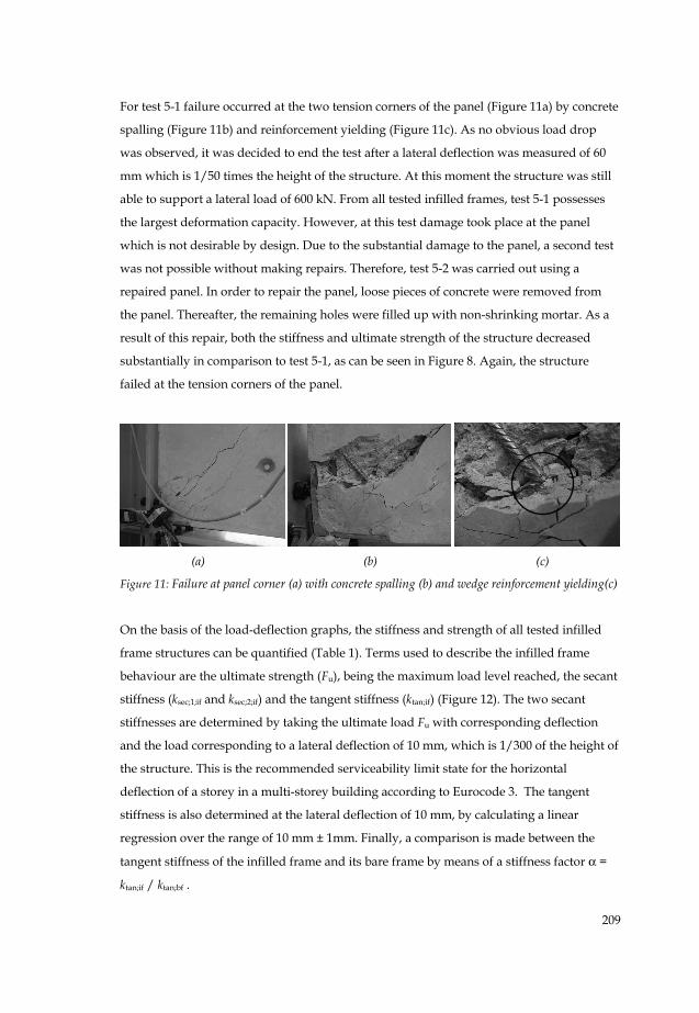
For test 5-1 failure occurred at the two tension corners of the panel (Figure 11a) by concrete
spalling (Figure 11b) and reinforcement yielding (Figure 11c). As no obvious load drop
was observed, it was decided to end the test after a lateral deflection was measured of 60
mm which is 1/50 times the height of the structure. At this moment the structure was still
able to support a lateral load of 600 kN. From all tested infilled frames, test 5-1 possesses
the largest deformation capacity. However, at this test damage took place at the panel
which is not desirable by design. Due to the substantial damage to the panel, a second test
was not possible without making repairs. Therefore, test 5-2 was carried out using a
repaired panel. In order to repair the panel, loose pieces of concrete were removed from
the panel. Thereafter, the remaining holes were filled up with non-shrinking mortar. As a
result of this repair, both the stiffness and ultimate strength of the structure decreased
substantially in comparison to test 5-1, as can be seen in Figure 8. Again, the structure
failed at the tension corners of the panel.
(a) (b) (c)
Figure 11: Failure at panel corner (a) with concrete spalling (b) and wedge reinforcement yielding(c)
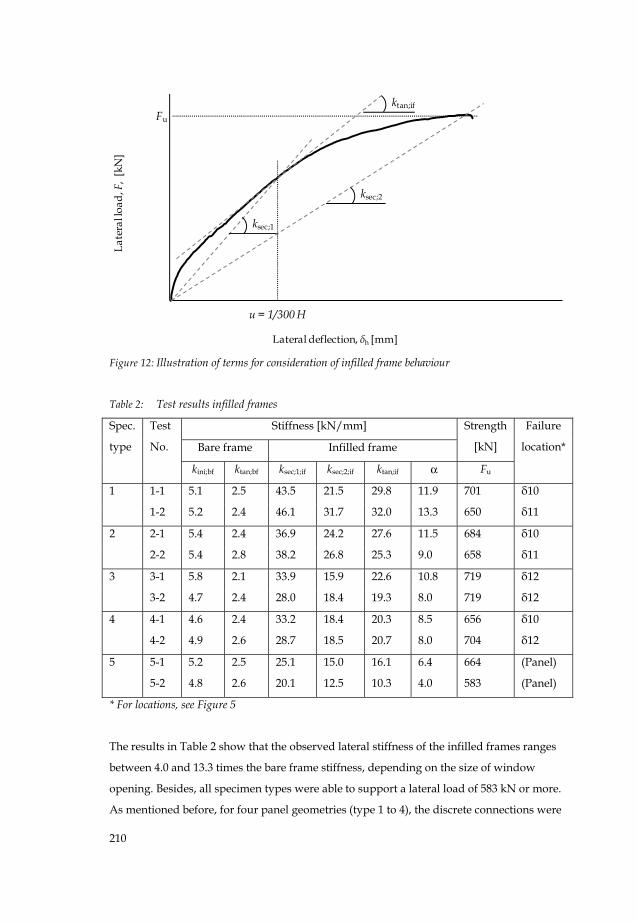
On the basis of the load-deflection graphs, the stiffness and strength of all tested infilled
frame structures can be quantified (Table 1). Terms used to describe the infilled frame
behaviour are the ultimate strength (Fu), being the maximum load level reached, the secant
stiffness (ksec;1;if and ksec;2;if) and the tangent stiffness (ktan;if) (Figure 12). The two secant
stiffnesses are determined by taking the ultimate load Fu with corresponding deflection
and the load corresponding to a lateral deflection of 10 mm, which is 1/300 of the height of
the structure. This is the recommended serviceability limit state for the horizontal
deflection of a storey in a multi-storey building according to Eurocode 3. The tangent
stiffness is also determined at the lateral deflection of 10 mm, by calculating a linear
regression over the range of 10 mm ± 1mm. Finally, a comparison is made between the
tangent stiffness of the infilled frame and its bare frame by means of a stiffness factor α =
ktan;if / ktan;bf .
Page 16
210
Late
ral l
oad,
F,
[kN
]
Lateral deflection, δh [mm]
ksec;1
ksec;2
Fu
u = 1/300 H
ktan;if
Figure 12: Illustration of terms for consideration of infilled frame behaviour
Table 2: Test results infilled frames
Stiffness [kN/mm]
Bare frame Infilled frame
Strength
[kN]
Spec.
type
Test
No.
kini;bf ktan;bf ksec;1;if ksec;2;if ktan;if α Fu
Failure
location*
1-1 5.1 2.5 43.5 21.5 29.8 11.9 701 δ10 1
1-2 5.2 2.4 46.1 31.7 32.0 13.3 650 δ11
2-1 5.4 2.4 36.9 24.2 27.6 11.5 684 δ10 2
2-2 5.4 2.8 38.2 26.8 25.3 9.0 658 δ11
3-1 5.8 2.1 33.9 15.9 22.6 10.8 719 δ12 3
3-2 4.7 2.4 28.0 18.4 19.3 8.0 719 δ12
4-1 4.6 2.4 33.2 18.4 20.3 8.5 656 δ10 4
4-2 4.9 2.6 28.7 18.5 20.7 8.0 704 δ12
5-1 5.2 2.5 25.1 15.0 16.1 6.4 664 (Panel) 5
5-2 4.8 2.6 20.1 12.5 10.3 4.0 583 (Panel)
* For locations, see Figure 5
The results in Table 2 show that the observed lateral stiffness of the infilled frames ranges
between 4.0 and 13.3 times the bare frame stiffness, depending on the size of window
opening. Besides, all specimen types were able to support a lateral load of 583 kN or more.
As mentioned before, for four panel geometries (type 1 to 4), the discrete connections were
Page 17
211
governing the strength of the structure as aimed at by design while for the test with the
largest opening (type 5) the infill panel failed first.
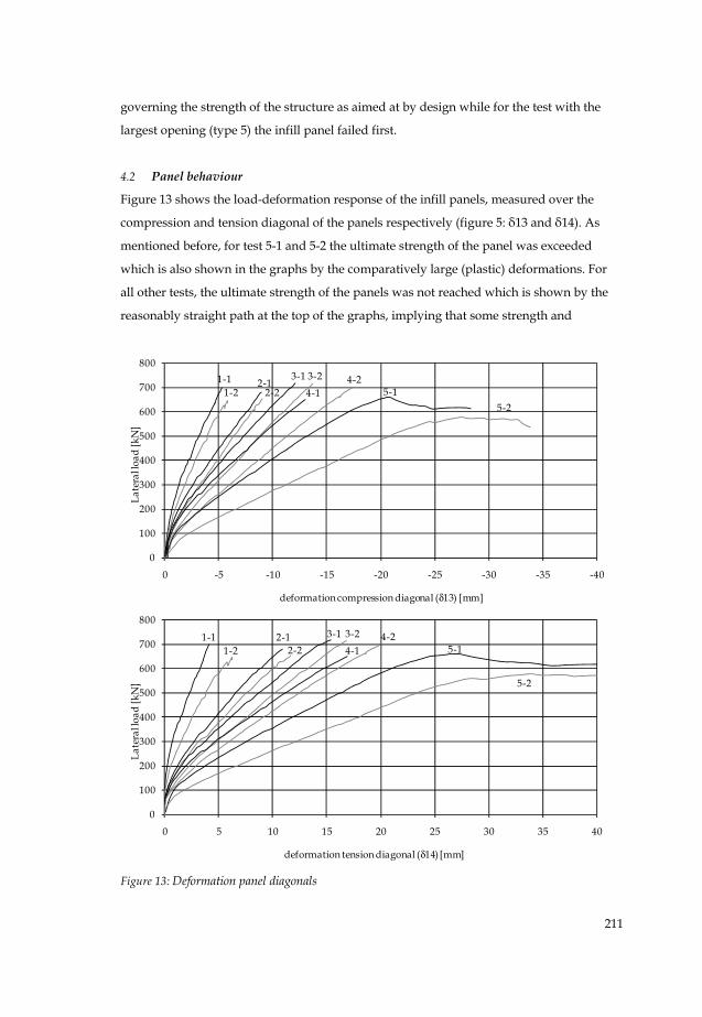
4.2 Panel behaviour
Figure 13 shows the load-deformation response of the infill panels, measured over the
compression and tension diagonal of the panels respectively (figure 5: δ13 and δ14). As
mentioned before, for test 5-1 and 5-2 the ultimate strength of the panel was exceeded
which is also shown in the graphs by the comparatively large (plastic) deformations. For
all other tests, the ultimate strength of the panels was not reached which is shown by the
reasonably straight path at the top of the graphs, implying that some strength and
0
100
200
300
400
500
600
700
800
-40-35-30-25-20-15-10-50
Late
ral l
oad
[kN
]
deformation compression diagonal (δ13) [mm]
1-11-2
2-13-1
4-1 5-14-23-2
2-25-2
0
100
200
300
400
500
600
700
800
0 5 10 15 20 25 30 35 40
Late
ral l
oad
[kN
]
deformation tension diagonal (δ14) [mm]
1-11-2
2-1 3-1
4-1 5-14-23-2
2-2
5-2
Figure 13: Deformation panel diagonals
Page 18
212
deformation capacity are left. Furthermore, the graphs indicate a decrease of panel stiffness
resulting from reusing the panels for the second test.
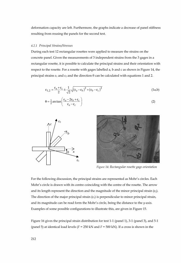
4.2.1 Principal Strains/Stresses
During each test 12 rectangular rosettes were applied to measure the strains on the
concrete panel. Given the measurements of 3 independent strains from the 3 gages in a
rectangular rosette, it is possible to calculate the principal strains and their orientation with
respect to the rosette. For a rosette with gages labelled a, b and c as shown in Figure 14, the
principal strains ε1 and ε2 and the direction θ can be calculated with equations 1 and 2.
( ) ( )2 21,2
12 2
a ca b b c
ε + εε = ± ε − ε + ε − ε (1a,b)
12
2arctan a b c
a c
⎛ ⎞ε − ε + εθ = ⎜ ⎟ε − ε⎝ ⎠ (2)
Figure 14: Rectangular rosette gage orientation
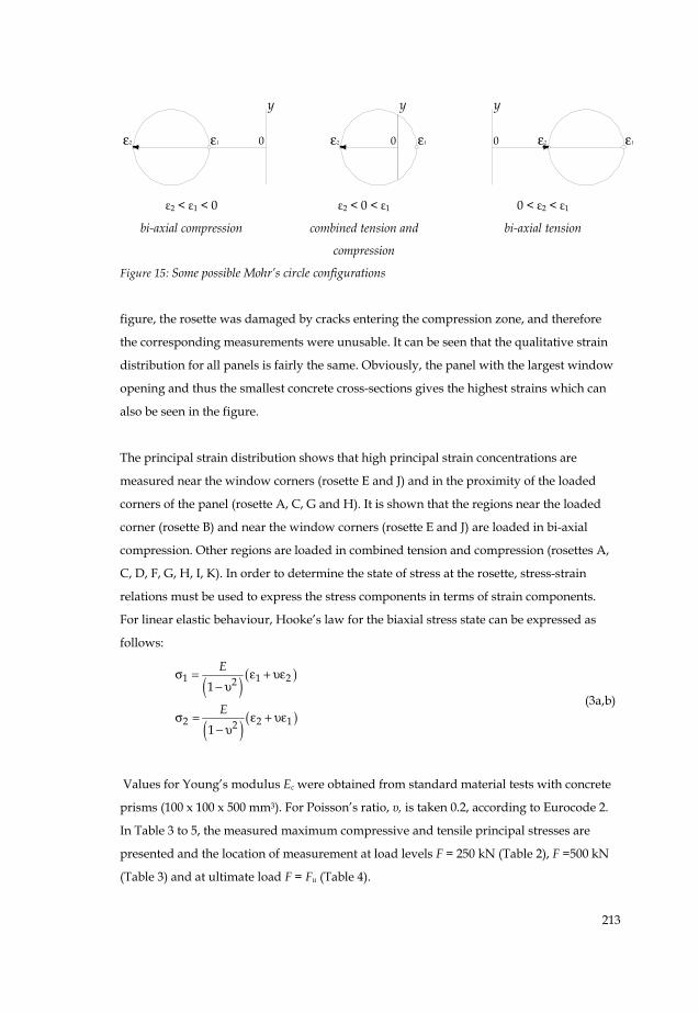
For the following discussion, the principal strains are represented as Mohr’s circles. Each
Mohr’s circle is drawn with its centre coinciding with the centre of the rosette. The arrow
and its length represent the direction and the magnitude of the minor principal strain (ε2).
The direction of the major principal strain (ε1) is perpendicular to minor principal strain,
and its magnitude can be read form the Mohr’s circle, being the distance to the y-axis.
Examples of some possible configurations to illustrate this, are given in Figure 15.
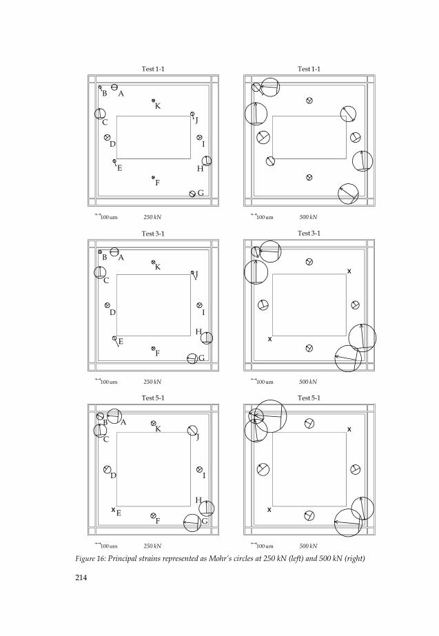
Figure 16 gives the principal strain distribution for test 1-1 (panel 1), 3-1 (panel 3), and 5-1
(panel 5) at identical load levels (F = 250 kN and F = 500 kN). If a cross is shown in the
ε2 c
b
a
ε1
θ
Page 19
213
ε1 ε10 0ε2 ε20 ε2 ε1
y yy
ε2 < ε1 < 0 ε2 < 0 < ε1 0 < ε2 < ε1
bi-axial compression combined tension and
compression
bi-axial tension
Figure 15: Some possible Mohr’s circle configurations
figure, the rosette was damaged by cracks entering the compression zone, and therefore
the corresponding measurements were unusable. It can be seen that the qualitative strain
distribution for all panels is fairly the same. Obviously, the panel with the largest window
opening and thus the smallest concrete cross-sections gives the highest strains which can
also be seen in the figure.
The principal strain distribution shows that high principal strain concentrations are
measured near the window corners (rosette E and J) and in the proximity of the loaded
corners of the panel (rosette A, C, G and H). It is shown that the regions near the loaded
corner (rosette B) and near the window corners (rosette E and J) are loaded in bi-axial
compression. Other regions are loaded in combined tension and compression (rosettes A,
C, D, F, G, H, I, K). In order to determine the state of stress at the rosette, stress-strain
relations must be used to express the stress components in terms of strain components.
For linear elastic behaviour, Hooke’s law for the biaxial stress state can be expressed as
follows:
( ) ( )
( ) ( )
1 1 22
2 2 12
1
1
E
E
σ = ε + υε− υ
σ = ε + υε− υ
(3a,b)
Values for Young’s modulus Ec were obtained from standard material tests with concrete
prisms (100 x 100 x 500 mm3). For Poisson’s ratio, υ, is taken 0.2, according to Eurocode 2.
In Table 3 to 5, the measured maximum compressive and tensile principal stresses are
presented and the location of measurement at load levels F = 250 kN (Table 2), F =500 kN
(Table 3) and at ultimate load F = Fu (Table 4).
Page 20
214
100 um 250 kN
Test 1-1
100 um 500 kN
Test 1-1
100 um 250 kN
Test 3-1
100 um 500 kN
Test 3-1
x
x
100 um 250 kN
Test 5-1
x
100 um 500 kN
Test 5-1
x
x
Figure 16: Principal strains represented as Mohr’s circles at 250 kN (left) and 500 kN (right)
B A
C
D
E
FG
K
J
I
H
B A
C
D
EF G
KJ
I
H
B A
C
D
EF G
KJ
I
H
Page 21
215
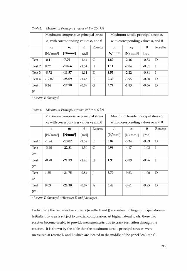
Table 3: Maximum Principal stresses at F = 250 kN
Maximum compressive principal stress
σ2 with corresponding values σ1 and θ
Maximum tensile principal stress σ1
with corresponding values σ2 and θ
σ1
[N/mm2]
σ2
[N/mm2]
θ
[rad]
Rosette σ1
[N/mm2]
σ2
[N/mm2]
θ
[rad]
Rosette
Test 1 -0.11 -7.79 -1.44 C 1.80 -2.46 -0.83 D
Test 2 0.37 -10.64 -1.54 H 1.11 -2.04 -0.81 I
Test 3 -8.72 -11.57 -1.11 E 1.53 -2.22 -0.81 I
Test 4 -12.87 -28.09 -1.45 E 2.30 -3.95 -0.88 D
Test
5*
0.24 -12.90 -0.09 G 3.74 -1.83 -0.66 D
*Rosette E damaged
Table 4: Maximum Principal stresses at F = 500 kN
Maximum compressive principal stress
σ2 with corresponding values σ1 and θ
Maximum tensile principal stress σ1
with corresponding values σ2 and θ
σ1
[N/mm2]
σ2
[N/mm2]
θ
[rad]
Rosette σ1
[N/mm2]
σ2
[N/mm2]
θ
[rad]
Rosette
Test 1 -1.94 -18.02 -1.52 C 3.87 -5.34 -0.89 D
Test
2**
-3.40 -22.81 -1.50 C 0.99 -4.17 -1.02 I
Test
3**
-0.78 -21.19 -1.48 H 1.95 -3.89 -0.96 I
Test
4*
1.35 -34.75 -0.84 J 3.70 -9.63 -1.00 D
Test
5**
0.03 -24.30 -0.07 A 5.48 -3.61 -0.85 D
*Rosette E damaged, **Rosettes E and J damaged
Particularly the two window corners (rosette E and J) are subject to large principal stresses.
Initially this area is subject to bi-axial compression. At higher lateral loads, these two
rosettes become unable to provide measurements due to crack formation through the
rosettes. It is shown by the table that the maximum tensile principal stresses were
measured at rosette D and I, which are located in the middle of the panel “columns”,
Page 22
216
Table 5: Maximum Principal stresses at F = Fu
Maximum compressive principal stress
σ2 with corresponding values σ1 and θ
Maximum tensile principal stress σ1
with corresponding values σ2 and θ
σ1
[N/mm2]
σ2
[N/mm2]
θ
[rad]
Rosette σ1
[N/mm2]
σ2
[N/mm2]
θ
[rad]
Rosette
Test 1 -1.73 -27.05 -0.64 G 4.21 -7.92 -0.93 D
Test
2***
-5.70 -32.27 -1.43 C 1.12 -5.57 -0.51 K
Test
3**
-3.74 -33.68 -1.44 H 1.83 -8.41 -1.14 D
Test
4**
-3.31 -30.52 -1.42 H 2.90 -6.39 -0.53 K
Test
5***
0.77 -34.72 -0.10 A 5.21 -5.70 -0.90 D
**Rosettes E and J damaged, ***Rosettes E, J and H damaged
having the smallest cross-section. However, it must be mentioned that no rosettes were
located in the actual tension zones of the panel, since they would be damaged there
directly. To be able to evaluate more thoroughly stresses and local deformations of the
concrete panels, the experiments will be supplemented by finite element analyses. The
measured principal strains and stresses will be used to compare with those determined
with the finite element model.
Finally, a comparison is made between the principal strain distribution found during the
first and second test respectively with the same infill panel. Figure 17 shows for panel 1 the
principal strain distribution found in the two tests at a lateral load F = 500 kN. It can be
observed that for most measured locations, the strains are higher during the panel’s second
test. This phenomenon is shown for all panels (Appendix A), and may be attributed to
changes in the aggregate and cement matrix after cracks are formed and closed again.
4.2.2 Cracks
During the tests, attention was paid to observe the formation of cracks in the infill panel. If
a crack was observed, it was marked on the panel and the end of the crack was marked
with the corresponding load at that moment. It must be mentioned that this method does
Page 23
217
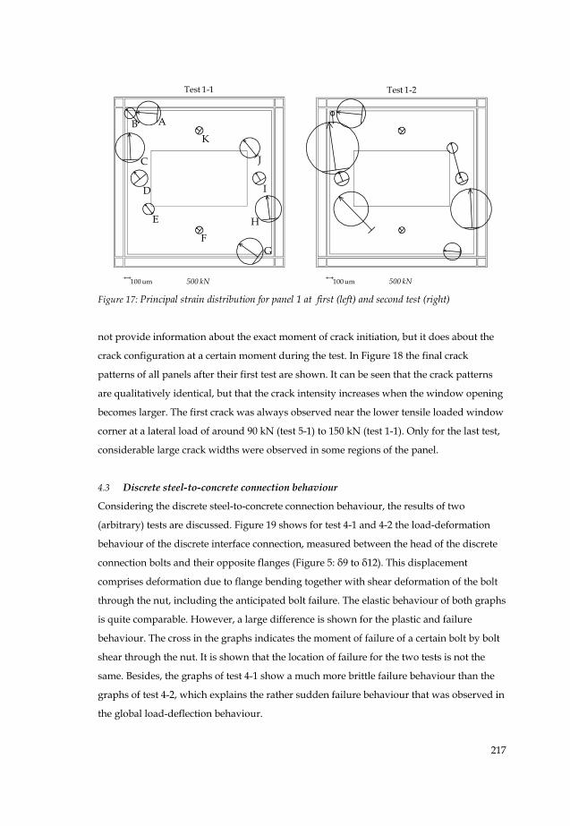
100 um 500 kN
Test 1-1
100 um 500 kN
Test 1-2
Figure 17: Principal strain distribution for panel 1 at first (left) and second test (right)
not provide information about the exact moment of crack initiation, but it does about the
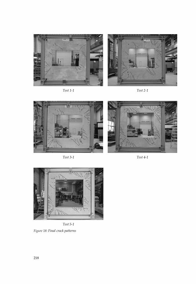
crack configuration at a certain moment during the test. In Figure 18 the final crack
patterns of all panels after their first test are shown. It can be seen that the crack patterns
are qualitatively identical, but that the crack intensity increases when the window opening
becomes larger. The first crack was always observed near the lower tensile loaded window
corner at a lateral load of around 90 kN (test 5-1) to 150 kN (test 1-1). Only for the last test,
considerable large crack widths were observed in some regions of the panel.
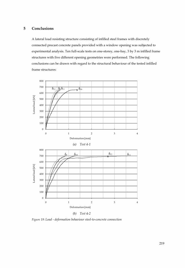
4.3 Discrete steel-to-concrete connection behaviour
Considering the discrete steel-to-concrete connection behaviour, the results of two
(arbitrary) tests are discussed. Figure 19 shows for test 4-1 and 4-2 the load-deformation
behaviour of the discrete interface connection, measured between the head of the discrete
connection bolts and their opposite flanges (Figure 5: δ9 to δ12). This displacement
comprises deformation due to flange bending together with shear deformation of the bolt
through the nut, including the anticipated bolt failure. The elastic behaviour of both graphs
is quite comparable. However, a large difference is shown for the plastic and failure
behaviour. The cross in the graphs indicates the moment of failure of a certain bolt by bolt
shear through the nut. It is shown that the location of failure for the two tests is not the
same. Besides, the graphs of test 4-1 show a much more brittle failure behaviour than the
graphs of test 4-2, which explains the rather sudden failure behaviour that was observed in
the global load-deflection behaviour.
B A
C
D
E
FG
K
J
I
H
Page 24
218
Test 1-1
Test 2-1
Test 3-1
Test 4-1
Test 5-1
Figure 18: Final crack patterns
Page 25
219
5 Conclusions
A lateral load resisting structure consisting of infilled steel frames with discretely
connected precast concrete panels provided with a window opening was subjected to
experimental analysis. Ten full-scale tests on one-storey, one-bay, 3 by 3 m infilled frame
structures with five different opening geometries were performed. The following
conclusions can be drawn with regard to the structural behaviour of the tested infilled
frame structures:
0
100
200
300
400
500
600
700
800
0 1 2 3 4
Late
ral l
oad
[kN
]
Deformation [mm]
δ9 δ10δ12 δ11 x
(a) Test 4-1
0
100
200
300
400
500
600
700
800
0 1 2 3 4
Late
ral l
oad
[kN
]
Deformation [mm]
δ9 δ10 δ12 δ11x
(b) Test 4-2
Figure 19: Load - deformation behaviour steel-to-concrete connection
Page 26
220
The discretely connected precast concrete infill panels with window openings significantly
improved the performance of the steel frames. The observed tangent stiffnesses range
between 10 kN/mm (panel 5) and 32 kN/mm (panel 1), being 4 and 13 times respectively
the bare frame stiffness. The ultimate strength of the infilled frames ranges from 583 to 719
kN. For test numbers 1-1 to 4-2, failure of the infilled frame structures occurred by shearing
of the steel-to-concrete connection bolts trough the nuts by stripping of the threads of the
bolts, which was also the desired failure mode. Some of these bolt failures were rather
sudden and brittle. The specific location of failure differs for all tests. After failure of the
bolts, the structure is still able to support the lateral load (fail safe concept). Failure of the
bolts does not result in failure of the structure, as force transmission is redirected to the
loaded corners of the frame by contact pressure between frame and panel (alternative load
path). Therefore, the rather brittle bolt failure behaviour can be considered as an acceptable
failure mechanism. For test 5-1 and 5-2, the infill panel was governing the strength of the
structure. It failed at the two tension corners of the panel by concrete spalling and
reinforcement yielding.
6 Future research
This research has recently been supplemented by finite element analyses. With the finite
element program DIANA, a finite element model has been developed that is able to predict
the load versus deflection relationship and the ultimate lateral load carrying capacity for
all tests. The numerical results were validated using the experimental data. With the
validated numerical model, a parametric study will be performed to study the infilled
frame performance by varying different parameters. Finally, design rules have to be
developed for the prediction of the stiffness and strength of this hybrid lateral load
resisting structure.
References
ASCE-ACI Committee 445 on Shear and Torsion (1998), ‘Recent Approaches to Shear
Design of Structural Concrete’, Journal of Structural Engineering, vol. 124, no. 12, pp.
1375-1417
EN 1992-1-1, ‘Eurocode 2: Design of concrete structures Part 1–1: General rules and rules
for buildings’, Brussels: CEN
Page 27
221
EN 1993-1-1, ‘Eurocode 3: Design of steel structures – Part 1–1: General rules and rules for
buildings’, Brussels: CEN
Hoenderkamp, J.C.D., Hofmeyer, H. and Snijder, H.H. (2005), ‘Composite behaviour of
steel frames with precast concrete infill panels’, in Hoffmeister, B. and Hechler, O.
(Eds.) Proc. of the 4th European conf. on steel & composite structures, vol. B, pp. (4.2-) 31-40,
Druck und Verlagshaus Mainz GmbH Aachen
Holmes, M. (1961), ‘Steel frames with brickwork and concrete infilling’, Proceedings of the
Institution of Civil Engineers, vol. 19, pp. 473-478
Liauw, T.C. (1972), ‘An approximate method of analyses for infilled frames with or without
opening’, Building Science, vol. 7, pp. 233-238
Liauw, T.C. and Kwan, K.H. (1983), ‘Plastic theory of non-integral infilled frames’,
Proceedings of the Institution of Civil Engineers, part 2, vol. 75, pp. 379-396
Mallick, D.V. and Garg, R.P. (1971), ‘Effect of openings on the lateral stiffness of infilled
frames’, Proceedings of the Institution of Civil Engineers, vol. 49, pp.193-210
Muttoni, A., Schwartz, J., Thurlimann, B. (1997), Design of Concrete Structures with Stress
Fields, Birkhauser, Berlin.
Ng’andu, B.M. (2006), Bracing steel frames with calcium silicate element walls, PhD-thesis,
Technische Universiteit Eindhoven, Department of Architecture, Building and
Planning
Stafford-Smith, B. (1966), ‘Behaviour of square infilled frames’, ASCE Journal of Structural
Division, vol. 92(ST1), pp. 381-403
Tang, R.B., Hoenderkamp, J.C.D. and Snijder, H.H. (2000), ‘Preliminary numerical research
on steel frames with precast reinforced concrete infill panels’, in Y.B. Yang, L.J. Leu and
S.H. Hsieh (Eds.) Proc. of the 1st int. conf. on structural stability and dynamics, pp. 575-580,
Taipei, Taiwan
Teeuwen, P.A., Kleinman, C.S. and Snijder, H.H. (2006), ‘The effect of window openings on
the composite behaviour of infilled steel frames with precast concrete panels’, in Sing-
Ping Chiew (Ed.) Proc. of the 8th int. conf. on steel, space & composite structures, pp. 185-
192, Kuala Lumpur
Teeuwen, P.A., Kleinman, C.S., Snijder, H.H. and Hofmeyer, H. (2007) ‘Experiments and
FE-model for a connection between steel frames and precast concrete infill panels’ in R.
Eligehausen, W. Fuchs, G. Genesio and P. Grosser (Eds.) Proc. of the 2nd Int. Symp. on
Connections between Steel and Concrete, pp. 1093-1102, Stuttgart: Ibidem-Verlag
Page 28
222
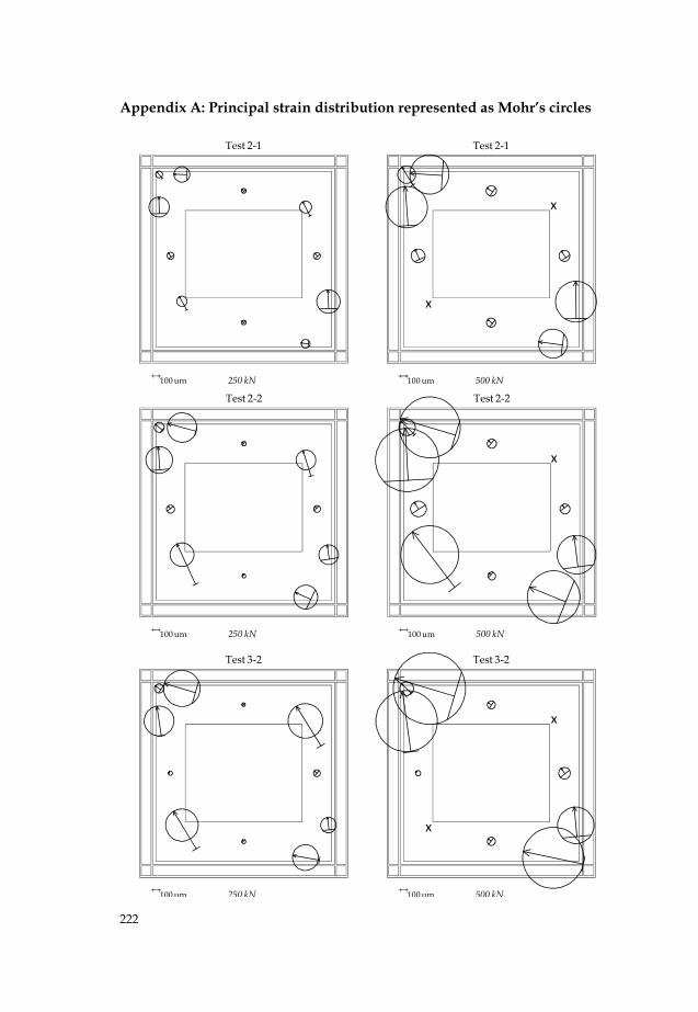
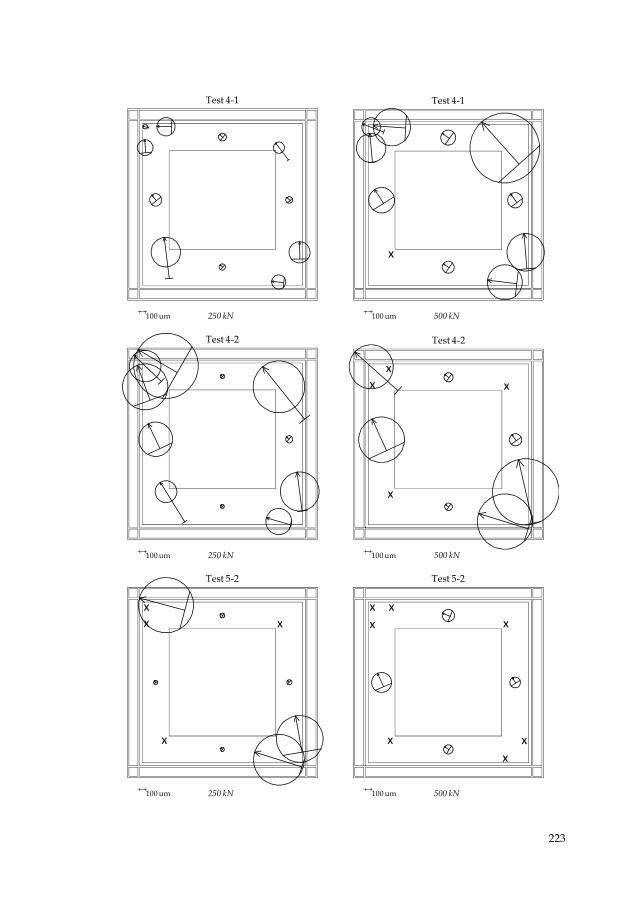
Appendix A: Principal strain distribution represented as Mohr’s circles
100 um 250 kN
Test 2-1
100 um 500 kN
Test 2-1
x
x
100 um 250 kN
Test 2-2
100 um 500 kN
Test 2-2
x
100 um 250 kN
Test 3-2
100 um 500 kN
Test 3-2
x
x
Page 29
223
100 um 250 kN
Test 4-1
100 um 500 kN
Test 4-1
x
100 um 250 kN
Test 4-2
100 um 500 kN
Test 4-2
x
x
xx
100 um 250 kN
Test 5-2
x
xxx
100 um 500 kN
Test 5-2
x
xxx
x
xx


![SEISMIC PERFORMANCE OF MASONRY-INFILLED · PDF fileSEISMIC PERFORMANCE OF MASONRY-INFILLED R.C. FRAMES: BENEFITS OF SLIGHT REINFORCEMENTS ... Zarnic and Tomazevic[38], Mosalam et al.](https://static.documents.pub/doc/80x56/5aa8fab27f8b9a7c188c3cdf/seismic-performance-of-masonry-infilled-performance-of-masonry-infilled-rc.jpg)


