6190 118 th Avenue North, Largo, FL 33773 (727) 544-2326 www.BeckwithElectric.com Products Defined by You, Refined by Beckwith GENERATOR PROTECTION Fundamentals and Application San Francisco Chapter Electrical Workshop: Measurement, Safety, and Protection “Knowledge is Power. Protect Your Important Assets!” Friday, May 29, 2015 Presented by:
Transcript
6190 118th Avenue North, Largo, FL 33773 (727) 544-2326 www.BeckwithElectric.com Products Defined by You, Refined by Beckwith
GENERATOR
PROTECTION
Fundamentals and Application
San Francisco Chapter
Electrical Workshop: Measurement, Safety, and Protection
“Knowledge is Power. Protect Your Important Assets!”
Friday, May 29, 2015
Presented by:
1
n
Presenter Contact Info
Wayne Hartmann is VP, Protection and Smart Grid Solutions forBeckwith Electric. He provides Customer and Industry linkage toBeckwith Electric’s solutions, as well as contributing expertise forapplication engineering, training and product development.
Wayne HartmannVP, Protection and Smart Grid Solutions
Before joining Beckwith Electric, Wayne performed in application, sales and marketing managementcapacities with PowerSecure, General Electric, Siemens Power T&D and Alstom T&D. During thecourse of Wayne's participation in the industry, his focus has been on the application of protection andcontrol systems for electrical generation, transmission, distribution, and distributed energy resources.
Wayne is very active in IEEE as a Senior Member serving as a Main Committee Member of the IEEEPower System Relaying Committee for 25 years. His IEEE tenure includes having chaired the RotatingMachinery Protection Subcommittee (’07-’10), contributing to numerous standards, guides,transactions, reports and tutorials, and teaching at the T&D Conference and various local PES andIAS chapters. He has authored and presented numerous technical papers and contributed to McGraw-Hill's “Standard Handbook of Power Plant Engineering, 2nd Ed.” 1
Review of generator construction and operation
Review grounding and connections
Discuss IEEE standards for generator protection Explore generator elements
• Internal faults (in the generator zone)• Abnormal operating conditions
• Generator zone• Out of zone (system)
• External faults
Discuss generator and power system interaction
Generator Protection
2
Objectives
2
Tripping considerations and sequential tripping
Discussion of tactics to improve security and dependability
Generator protection upgrade considerations Advanced attributes for security, reliability and
maintenance use
Review Setting, Commissioning and Event Investigation Tools
Q & A
ObjectivesGenerator Protection
3
Generator Construction:Simple Bock Diagram
G
Prime Mover(Mechanical Input)
Three-PhaseElectricalOutput
iaibic
DC Field Source
Generator Protection
4
3
Applying Mechanical Input
1. Reciprocating Engines
2. Hydroelectric
3. Gas Turbines (GTs, CGTs)
4. Steam Turbines (STs)
1
42
3
Generator Protection
5
Applying FieldStatic Exciter
• DC is induced in the rotor• AC is induced in the stator
6
4
Cylindrical rotor seen in Recips, GTs and STs
Salient pole rotor seen in Hydros More poles to obtain nominal frequency at low RPM
Eq: f= [RPM/60] * [P/2] = [RPM * P] / 120
Cylindrical (Round) Salient
Generator ProtectionRotor Styles
7
Cylindrical Rotor & StatorGenerator Protection
8
5
Generator Protection
Cylindrical Rotor & Stator
9
Cylindrical Rotor & Stator
10
6
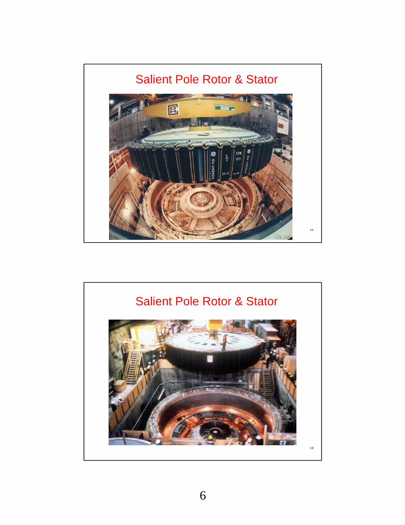
Salient Pole Rotor & StatorGenerator Protection
11
Salient Pole Rotor & StatorGenerator Protection
12
7
Generator Behavior During Short Circuits Generator Protection
13
Generator Short-Circuit Current Decay
Sho
rt-C
ircui
t Cur
rent
Generator Protection
14
8
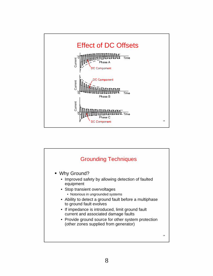
Effect of DC OffsetsThree-Phase Fault
Cur
rent
Cur
rent
Cur
rent
Generator Protection
15
Grounding Techniques
Why Ground?• Improved safety by allowing detection of faulted
equipment• Stop transient overvoltages
• Notorious in ungrounded systems
• Ability to detect a ground fault before a multiphase to ground fault evolves
• If impedance is introduced, limit ground fault current and associated damage faults
• Provide ground source for other system protection (other zones supplied from generator)
Generator Protection
16
9
Types of Generator Grounding
Low Impedance• Good ground source
• The lower the R, the better the ground source
• The lower the R, the more damage to the generator on internal ground fault
• Can get expensive as resistor voltage rating goes up
• Generator will be damaged on internal ground fault• Ground fault current typically 200-
400 A
G
R
System
GroundingResistor
Generator Protection
17
Types of Generator Grounding
High Impedance Creates “unit connection” System ground source obtained from
Multiple Bus (High Z), 1 or Multiple Generators- Connected through one unit xfmr- Likely in large industrial and utility systems- No circulating current issue- Adds complexity to discriminate ground fault source
Special CTs needed for sensitivity, and directional ground overcurrent elements
Generator Protection
Types of Generator Connections
28
15
Generator ProtectionUnit Connected
29
Generators experience shorts and abnormal electrical conditions Proper protection can mitigate damage to the
machine Proper protection can enhance generation
security Generator Protection: Shorts circuits in the generator Uncleared faults on the system Abnormal electrical conditions may be caused by the
generator or the system
Generator Protection Overview
Generator Protection
30
16
Generator Protection Overview
Short Circuits
In Generator• Phase Faults• Ground Faults
On System• Phase Faults• Ground Faults
Generator Protection
31
Internal and External Short Circuits
Generator Protection Overview
Generator Protection
32
17
Generator Protection Overview
Abnormal Operating Conditions Abnormal Frequency Abnormal Voltage Overexcitation Field Loss Loss of Synchronism Inadvertent Energizing Breaker Failure Loss of Prime Mover Blown VT Fuses Open Circuits / Conductors
Generator Protection
33
Abnormal Operating Conditions
"Wild" Power SystemG
Exciter
Loss of Field
Loss of Field
Overexcitation
Overexcitation
Overexcitation
OpenCircuits
Loss of Synchronism
InadvertentEnergizing,Pole Flashover
AbnormalFrequency
AbnormalFrequency
Breaker FailureReverse Power
Generator Protection Overview
Generator Protection
34
18
Latest developments reflected in:
- Std. 242: Buff Book
- C37.102: IEEE Guide for Generator Protection
- C37.101: IEEE Guide for AC Generator Ground Protection
- C37.106: IEEE Guide for Abnormal Frequency Protection for Power Generating Plants
ANSI/IEEE StandardsGenerator Protection
35
These are created/maintained by the IEEE PES PSRC & IAS
Typical Unit Connected Generator
(C37.102)
Unit Connected,High Z Grounded
36
19
Stator Ground Fault
Traditional stator ground fault protection schemes include:• Neutral overvoltage• Various third harmonic voltage-dependent
schemes
These exhibit sensitivity, security and clearing speed issues that may subject a generator to prolonged low level ground faults that may evolve into damaging faults
37
Neutral Overvoltage (59G)
59G provides 95% stator winding coverage
38
20
Fault Position
Vol
tage
at N
eutr
al(6
0 H
z)
0% 50% 100%0
0.5pu
1.0pu
N T
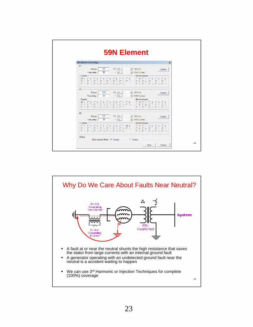
59N ElementGenerator Protection
Neutral grounding transformer (NGT) ratio selected that provides 120 to 240V for ground fault at machine terminals Max L-G volts =13.8kV / 1.73 = 7995V
Max NGT volts sec. = 7995V / 120V = 66.39 VTR
39
59G System Ground Fault Issue
GSU provides capacitive coupling for system ground faults into generator zone
Use two levels of 59G with short and long time delays for selectivity
Cannot detect ground faults at/near the neutral (very important) 40
21
Multiple 59G Element Application
59G-1 is blind to the capacitive coupling by the GSU. Short time delay
• 59G-2 is set to 5%, which may include the effects of capacitive coupling by the GSU – Long time delay
Tim
e (c
ycle
s)
41
Use of Symmetrical Component Quantitiesto Supervise 59G Tripping Speed
• Both V2 and I2 implementation have been applied– A ground fault in the generator zone produces primarily zero sequence
voltage
– A fault in the VT secondary or system (GSU coupled ) generates negative sequence quantities in addition to zero sequence voltage
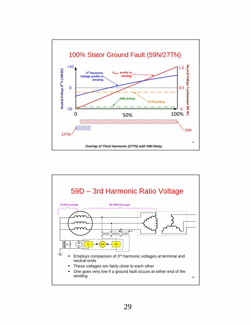
Employs comparison of 3rd harmonic voltages at terminal and neutral ends
These voltages are fairly close to each other One goes very low if a ground fault occurs at either end of the
winding
59N
0-15% Coverage
59D 3V0VN
85-100% Coverage
Generator Protection
58
30
59D – 3rd Harmonic Ratio Voltage
Generator Protection
59
Stator Ground Faults: 59N, 27TN, 59D
Generator Protection
60
31
Typical value of 3rd harmonic (V3rd) is around 1.7V, 27TN set to pick up at 1.1V.
A line breaker tripped isolating plant, and they experienced a 27TN operation.
Oscillograph shows the V3rd decreased from 1.7V to 1.0V as the frequency went from 60 Hz to 66Hz, (only 110% over speed).
This is well below the 180-200% over speed condition that is often cited as possible with hydros upon full load rejection.
What happens to 59N?
3rd Harmonic Voltage Decrease During an Over Speed Condition in a 45MW Hydro Generator
Generator Protection
61
3rd Harmonic in Hydro GeneratorsGenerator Protection
62
32
Subharmonic Injection: 64S
20Hz injected into grounding transformer secondary circuit
Rise in real component of injected current suggests resistive ground fault
Ignores capacitive current due to isophase bus and surge caps Uses it for self-diagnostic and system
integrity
Coupling FilterVoltageInjector
Measurements
I
Natural Capacitance
Notes:Subharmonic injection frequency = 20 HzCoupling filter tuned for subharmonic frequencyMeasurement inputs tuned to respond to subharmonic frequency
V
VoltageInjector
20Hz
63
Subharmonic Injection: 64S
Functions on-line and off-line Power and frequency independent
64
33
64S – Subharmonic Injection
65
Stator Ground Faults: High Z Element Coverage
Generator Protection
66
34
95% stator ground fault provided by 59NTuned to the fundamental frequency• Must work properly from 10 to 80 Hz to provide protection during
startup
Additional coverage near neutral (last 5%) provided by:• 27TN: 3rd harmonic undervoltage• 59D: Ratio of 3rd harmonic at terminal and neutral ends of
winding
Full 100% stator coverage by 64S• Use of sub-harmonic injection• May be used when generator is off-line• Immune to changes in loading (MW, MVAR)
Stator Ground Fault:High Z Grounded Machines
67
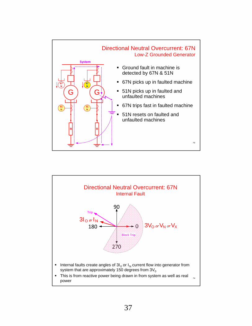
Stator Ground Fault: Low Z Grounded Machines
51N element typically applied Coordinate with system
ground fault protection for security and selectivity
Results in long clearing time for internal machine ground fault
Single generator, with system supplying ground current, or multiple generators as ground current sources
67N
Single generator, with system supplying ground current, or multiple generators as ground current sources
0%
100%
50%
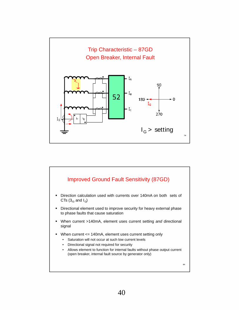
87GD
In Low-Z schemes, you cannot provide 100% stator ground fault protection
Protection down to last 5%-10% near neutral using 51N
Protection down to last 5% using 67N or 87GD
Seletivity and high speed possible with 67N or 87GD with in zone fault
Generator Protection
83
Field/Rotor Ground Fault
Traditional field/rotor circuit ground fault protection schemes employ DC voltage detection Schemes based on DC principles are subject to
security issues during field forcing, other sudden shifts in field current and system transients
84
43
Brushed and “Brushless” Excitation
Brushed
“Brushless”
85
Field/Rotor Ground Fault (64F)
To mitigate the security issues of traditional DC-based rotor ground fault protection schemes, AC injection based protection may be used AC injection-based protection ignores the
effects of sudden DC current changes in the field/rotor circuits and attendant DC scheme security issues
86
44
DC-Based 64F
87
Advanced AC Injection Method
Exciter
Field
+
ExciterBreaker
–
CouplingNetwork
ProtectiveRelay
Signal Measurement& Processing
Square Wave Generator
88
45
Advanced AC Injection Method: Advantages
Scheme is secure against the effects of DC transients in the field/rotor circuit DC systems are prone to false alarms and false trips, so they
sometimes are ignored or rendered inoperative, placing the generator at risk
The AC system offers greater security so this important protection is not ignored or rendered inoperative
Scheme can detect a rise in impedance which is characteristic of grounding brush lift-off In brushless systems, the measurement brush may be
periodically connected for short time intervals
The brush lift-off function must be blocked during the time interval the measurement brush is disconnected
89
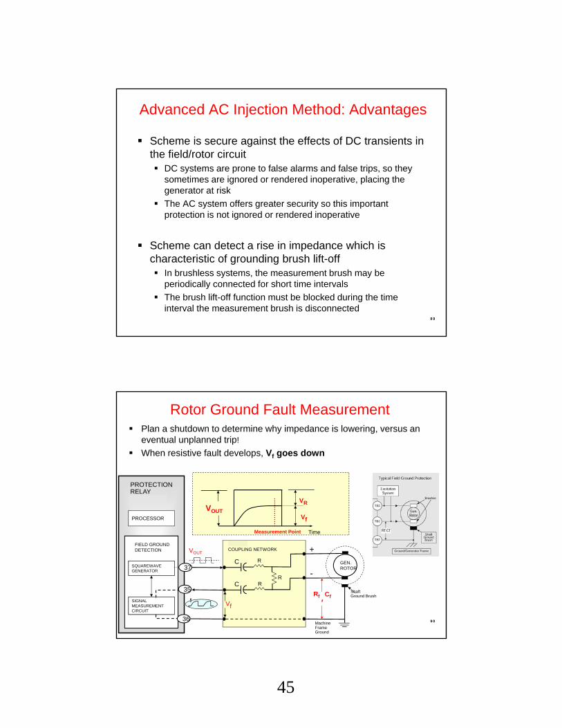
Rotor Ground Fault Measurement
PROCESSOR
SQUAREWAVEGENERATOR
PROTECTIONRELAY(M-3425A)
FIELD GROUNDDETECTION
SIGNALMEASUREMENTCIRCUIT
37
VOUT
36
35
Measurement Point Time
Vf
VRVOUT
M-3921COUPLING NETWORK
GEN.ROTOR
MachineFrameGround
+
-RR
RC
C
Vf
ShaftGround BrushRf Cf,
Generator Protection
Plan a shutdown to determine why impedance is lowering, versus an eventual unplanned trip!
When resistive fault develops, Vf goes down
90
46
Brush Lift-Off Measurement
PROCESSOR
SQUAREWAVEGENERATOR
PROTECTIONRELAY(M-3425A)
FIELD GROUNDDETECTION
SIGNALMEASUREMENTCIRCUIT
37
VOUT
Vf SignalVALARM
VNORMAL
Brush Lift-Off Voltage
Measurement Point
VNORMAL = Normal Voltage forHealthy Brush Contact
VALARM = Alarm Voltage when BrushResistance Increases dueto poor contact
87G – Phase Differential (primary for in-zone faults)
• What goes into zone must come out
• Challenges to Differential• CT replication issues: Remenant flux causing saturation• DC offset desensitization for energizing transformers and large load
pick up• Must work properly from 10 Hz to 80Hz so it operates correctly at off-
nominal frequencies from internal faults during startup• May require multiple elements for CGT static start
• Tactics:• Use variable percentage slope• Operate over wide frequency range• Uses IRMS/IFUND to adaptively desensitize element when challenged
by large DC offset and harmonics for security DC offset can occur from black starting and close-in faults
Stator Phase Faults
Generator Protection
94
48
Through Current: Perfect Replication
0
-4
+4
4 pu
87
0 2 4 6 8 10
2
4
6
8
10
BA IR = |I1| + |I2|
ID = I1 + I2
B
TRIP
RESTRAIN
2 Node Bus
(0,0) (4,-4)
A
Generator Protection
95
Through Current: Imperfect Replication
0
-4
+4
0 2 4 6 8 10
2
4
6
8
10
C
A
A
ID = I1 + I2
B
B (2, -2)
(0,0)
(1, -3)
C
4 pu
87
IR = |I1| + |I2|
2 Node Bus
TRIP
RESTRAIN
Generator Protection
96
49
Internal Fault: Perfect Replication
0
2
+2
0 2 4 6 8 10
2
4
6
8
10
BA
A
ID = I1 + I2
B
TRIP
RESTRAIN
2 pu
87
2 Node Bus
2 pu
(2, 2)(0, 0)
IR = |I1| + |I2|
Generator Protection
97
Internal Fault: Imperfect Replication
0
-2
+2
2 pu
0 2 4 6 8 10
2
4
6
8
10
A B
ID = I1 + I2
B
TRIP
RESTRAIN
2 pu
87
2 Node Bus
(2, 0.5)(0, 0)
IR = |I1| + |I2|
A
Generator Protection
98
50
0.3A
10%
40%
0.6A
CTC = CT Correction Ratio = Line CTR/Neutral CTRUsed when Line and Neutral CTs have different ratios
87 Characteristic
Generator Protection
99
87 Setting
Generator Protection
100
51
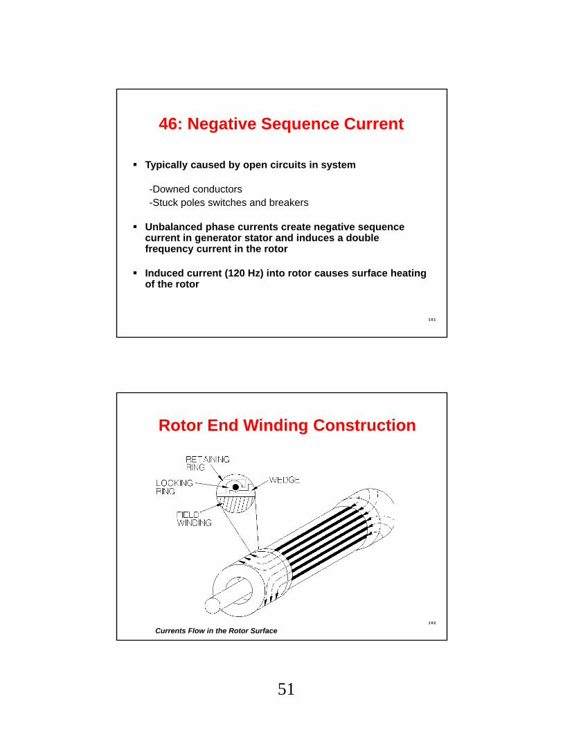
46: Negative Sequence Current
Generator Protection
Typically caused by open circuits in system
-Downed conductors-Stuck poles switches and breakers
Unbalanced phase currents create negative sequence current in generator stator and induces a double frequency current in the rotor
Induced current (120 Hz) into rotor causes surface heating of the rotor
Sensitivity restricted and cannot detect I2 levels less than 60% of generator rating
Fault backup provided
Generally insensitive to load unbalances or open conductors
46: Negative SequenceElectromechanical Relays
Generator Protection
106
54
Protects generator down to its continuous negative sequence current (I2) rating vs. electromechanical relays that don’t detect levels less than 60%
Fault backup provided
Can detect load unbalances
Can detect open conductor conditions
46: Negative Sequence Digital Relay
Generator Protection
107
Measured• High Volts/Hertz ratio• Normal = 120V/60Hz = 1pu• Voltage up, and/or frequency low, make event
Issues• Overfluxing of metal causes localized heating• Heat destroys insulation• Affects generators and transformers
Overexcitation (24)
Generator Protection
108
55
Causes of V/HZ Problems
Generator voltage regulator problems
- Operating error during off-line manual regulator operation
- Control failure
- VT fuse loss in voltage regulator (AVR) sensing voltage
System problems
- Unit load rejection: full load, partial rejection- Power system islanding during major disturbances- Ferranti effect- Reactor out- Capacitors in- Runaway LTCs
Overexcitation (24)Generator Protection
109
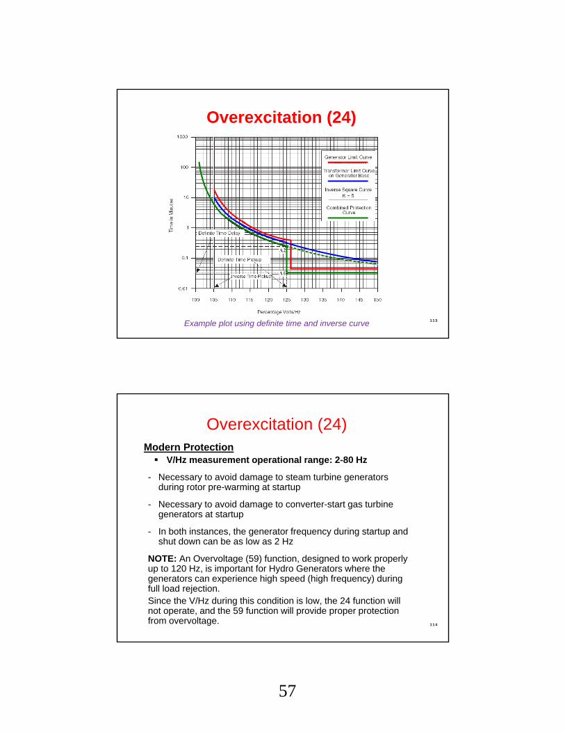
Protects machine against excessive V/Hz (overfluxing)
Legacy Protection
Typically “stair-step” two definite time setpoints
Two definite time elements- One may be used to alarm
Example plot using definite time and inverse curve
Generator Protection
Overexcitation (24)
113
Modern Protection V/Hz measurement operational range: 2-80 Hz
- Necessary to avoid damage to steam turbine generators during rotor pre-warming at startup
- Necessary to avoid damage to converter-start gas turbine generators at startup
- In both instances, the generator frequency during startup and shut down can be as low as 2 Hz
NOTE: An Overvoltage (59) function, designed to work properly up to 120 Hz, is important for Hydro Generators where the generators can experience high speed (high frequency) during full load rejection. Since the V/Hz during this condition is low, the 24 function will not operate, and the 59 function will provide proper protectionfrom overvoltage.
Overexcitation (24)Generator Protection
114
58
Generator Protection
Generator effects
Synchronous generator becomes induction
Slip induced eddy currents heat rotor surface
High reactive current drawn by generator overloads stator
Power system effects
Loss of reactive support
Creates a reactive drain
Can trigger system/area voltage collapse
40: Loss of FieldCan adversely effect the generator and the system!!
115
WATT
VAROUT
VARIN
Normal
Lossof
Field
Typical Generator Capability Curve
Generator capability curve viewed on the P-Q plane.
This info must be converted to the R-X plane.
116
59
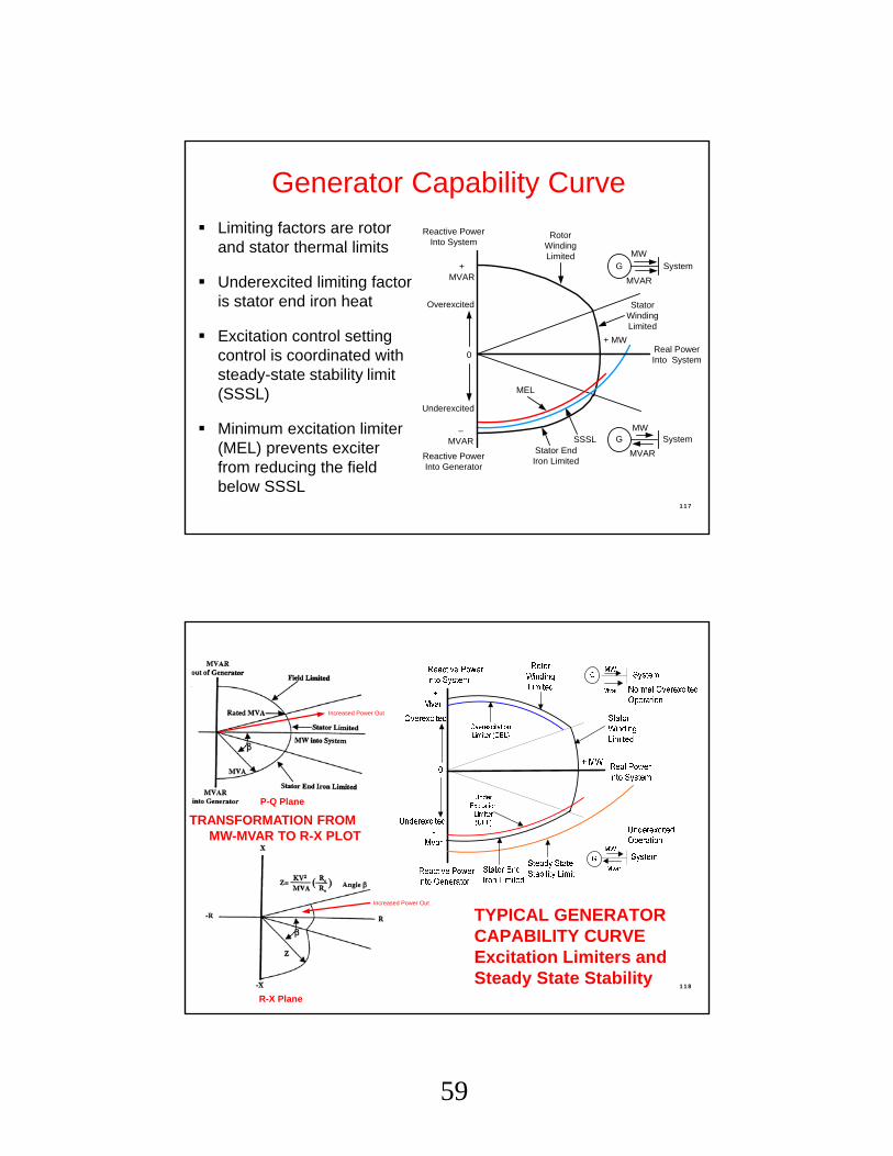
Generator Capability Curve
Limiting factors are rotor and stator thermal limits
Underexcited limiting factoris stator end iron heat
Excitation control setting control is coordinated with steady-state stability limit (SSSL)
Minimum excitation limiter (MEL) prevents exciter from reducing the field below SSSL
Reactive Power Into System
Reactive Power Into Generator
Rotor Winding Limited
MEL
Stator End Iron Limited
SSSL
Stator Winding Limited
+ MWReal Power Into System
0
+MVAR
Overexcited
Underexcited
–MVAR G
MVAR
MWSystem
MVAR
G
MW
System
Generator Protection
117
Increased Power Out
Increased Power Out
P-Q Plane
R-X Plane
TYPICAL GENERATOR CAPABILITY CURVEExcitation Limiters and Steady State Stability
Generator Protection
TRANSFORMATION FROM MW-MVAR TO R-X PLOT
118
60
Two Zone Offset Mho Impedance w/Directional UnitGE WestinghouseCEH KLF
Loss of FieldGE and Westinghouse Methods
119
Diameter = 1.0 puOffset =
Diameter = Xd
–R
–X
+X
+R
dX
2
Machine Capability
MELSSSL
dX
2
Loss of FieldTwo Zone Offset Mho
Generator Protection
120
dX
2
61
Loss of FieldImpedance w/Direction Unit
121
dX
2
Two Zone Offset Mho Impedance w/Directional Unit
Better ability to match capability curves after conversion from P-Q to R-X plane
40: Multiple Mho ImplementationsMay Provide Better Fit Reactive Capability Curves
Generator Protection
122
dX
2
62
Positive sequence quantities used to maintain security and accuracy over a wide frequency range.
Must work properly from 50 to 70 Hz (60 Hz systems) Required to operate correctly (and not misoperate) with wide frequency variations possible during power swing conditions.
May employ best of both methods to optimize coordination.
- Provide maximum coordination between machine limits, limiters and protection
- Offset mho for Z1. Fast time for true Loss of Field event.- Impedance with directional unit and slower time for Z2. Better
match of machine capability curve. Also able to ride through stable swing.
- May employ voltage supervision for accelerated tripping of Z2 (slower zone) in cases of voltage collapse where machine is part of the problem, importing VArs.
40: Loss of Field
Generator Protection
123
Generator Protection
Generator Lost Field, then went Out-of-Step!!!
Loss of Field Event
124
63
Two Zone Offset Mho Impedance w/Directional Unit
Better ability to match capability curves after conversion from P-Q to R-X plane
Generator Protection
125
40: Multiple Loss-of-Field Mho Implementationsto Better Fit Reactive Capability Curves
Two Zone Offset Mho Impedance w/Directional Unit
Better ability to match capability curves after conversion from P-Q to R-X plane
40: Multiple Loss-of-Field Mho Implementationsto Better Fit Reactive Capability Curves
Generator Protection
126
35.0Ω
5.0Ω
64
Phase distance backup protection may be prone to tripping on stable swings and load encroachment
- Employ three zones
Z1 can be set to reach 80% of impedance of GSU for 87G back-up.
Z2 can be set to reach 120% of GSU for station bus backup, or to overreach remote bus for system fault back up protection. Load encroachment blinder provides security against high loads with long reach settings.
Z3 may be used in conjunction with Z2 to form out-of-step blocking logic for security on power swings or to overreach remote bus for system fault back up protection. Load encroachment blinder provides security against high loads with long reach settings.
- Use minimum current supervision provides security against loss of potential (machine off line)
Generator Protection21: Distance ElementWith Power Swing Block & Load Encroachment Blocking for Z1 and Z2
130
66
3-Zone 21 Function with OSB/Load Encroachment
Generator Protection
131
0.0Ω
60.0Ω
80.0°
40°
25.0Ω
21 Settings
Generator Protection
132
67
Types of Instability
• Steady State: Steady Voltage and Impedance (Load Flow)• Transient: Fault, where voltage and impedance change rapidly• Dynamic: Oscillations from AVR damping (usually low f)
Occurs with unbalance of load and generation
• Short circuits that are severe and close• Loss of lines leaving power plant (raises impedance of loadflow
path)• Large losses or gains of load after system break up
Generator accelerates or decelerates, changing the voltage angle between itself and the system
• Designed to cover the situation where electrical center of power system disturbance passes through the GSU or the generator itself
• More common with modern EHV systems where system impedance has decreased compared to generator and GSU impedance
• When a generator goes out-of-step (synchronism) with the power system, high levels of transient shaft torque are developed.
• If the pole slip frequency approaches natural shaft resonant frequency, torque produced can break the shaft
• High stator core end iron flux can overheat and short the generator stator core
• GSU subjected to high transient currents and mechanical stresses
Generator Out-of-Step Protection (78)
Generator Protection
134
68
Stability
g se g s
E EP sin
X g s
max
E EP
X
g gE
s sE
For maximum power transfer:• Voltage of GEN and SYSTEM should be nominal – Faults lower voltage• Impedance of lines should be low – lines out raise impedance
Es - System VoltageEg - Generator Voltages - System Voltage Phase Angleg - Generator Voltage Phase AnglePe - Electrical Power
Generator Protection
135
Single Blinder Scheme
One pair of blinders (vertical lines)
Supervisory offset mho
Blinders limit reach to swings near the generatorX d
Gen
Trans
System
X
R
Mho Element
BA
Blinder Elements
B ElementPickup
A ElementPickup
C
136
Generator Protection
69
Graphical Method: 78
X d
Gen
GSU
System
X
R
Mho Element
M
BA
P
Blinder Elements
B ElementPickup
A ElementPickup
XT
XS
2X D + XT + XS
Swing Locus
Generator Protection
137
Graphical Method: 78
X d
Gen
GSU
System
X
R
Mho Element
BA
Blinder Elements
B ElementPickup
A ElementPickup
XT
XS
2X D + XT + XS
Unstable Swing
Stable Swing
Generator Protection
138
70
Generator ProtectionOut-of-Step (Loss of Synchronism) Event
139
Dependability Concerns
Positive sequence quantities used to maintain security and accuracy over a wide frequency range.
Required to operate correctly (and not misoperate) with wide frequency variations possible during power swing conditions• Must work properly from 50 to 70 Hz (60 Hz systems).
Generator Out-of-Step Protection (78)
Generator Protection
140
71
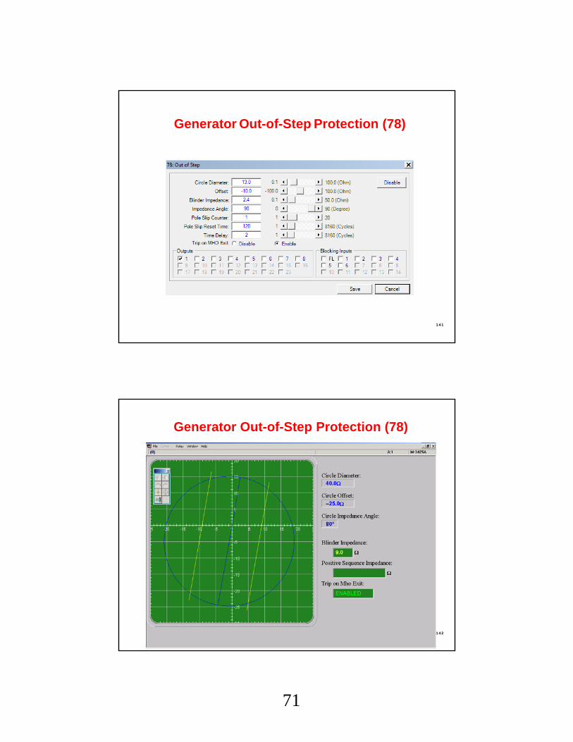
Generator Out-of-Step Protection (78)
Generator Protection
141
Generator Out-of-Step Protection (78)
Generator Protection
142
72
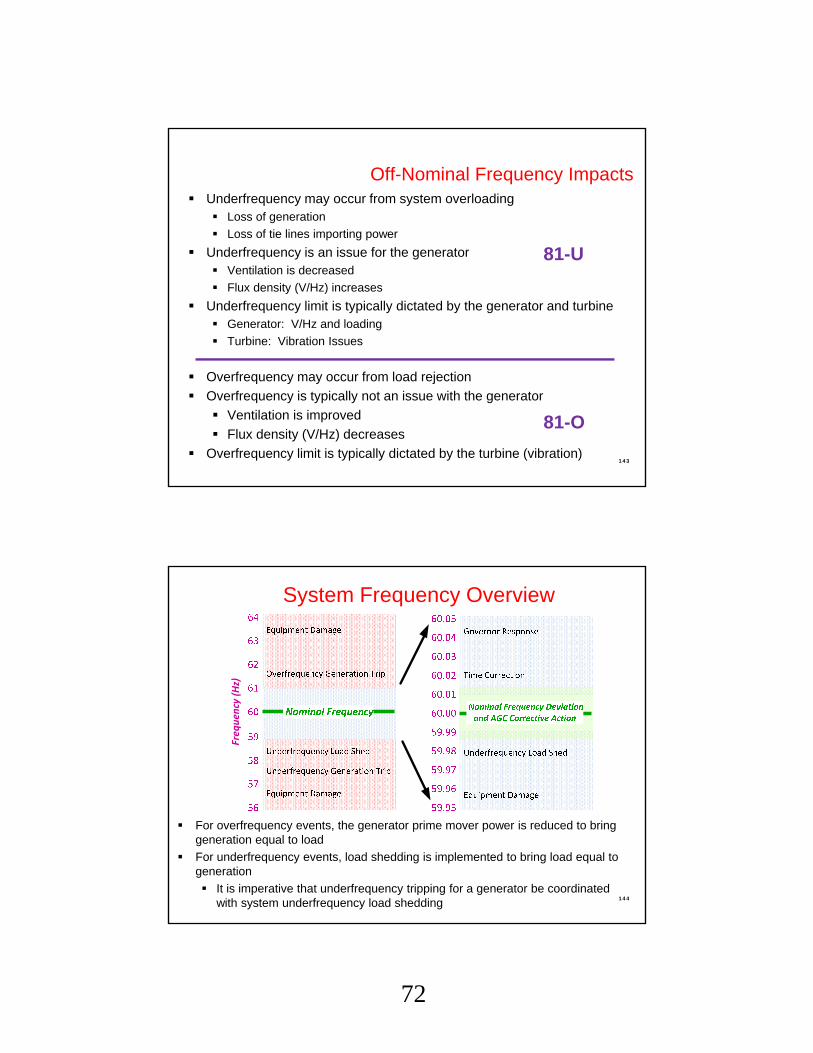
Off-Nominal Frequency Impacts Underfrequency may occur from system overloading
Loss of generation
Loss of tie lines importing power
Underfrequency is an issue for the generator Ventilation is decreased
Flux density (V/Hz) increases
Underfrequency limit is typically dictated by the generator and turbine Generator: V/Hz and loading
Turbine: Vibration Issues
Overfrequency may occur from load rejection
Overfrequency is typically not an issue with the generator
Ventilation is improved
Flux density (V/Hz) decreases
Overfrequency limit is typically dictated by the turbine (vibration)
81-U
81-O
143
Generator Protection
System Frequency Overview
For overfrequency events, the generator prime mover power is reduced to bring generation equal to load
For underfrequency events, load shedding is implemented to bring load equal to generation
It is imperative that underfrequency tripping for a generator be coordinated with system underfrequency load shedding 144
Generator Protection
Freq
uen
cy (
Hz)
73
81 – Four Step Frequency
- Any step may be applied over- or underfrequency- High accuracy – 1/100th Hz (0.01 Hz)- Coordination with System Load Shedding
81A – Underfrequency Accumulator
- Time Accumulation in Six Underfrequency Bands- Limits Total Damage over Life of Machine
Used to protect generator from motoring during loss of prime mover power
Motoring: Wastes power from the system May cause heating in steam turbines as ventilation is greatly reduced Steam and dewatered hydro can motor with very little power; <=1%
rated CGT and Recip typically use 10-25% of rated power to motor
Generators are often taken off the system by backing off the power until importing slightly so not to trip with power export and go into overspeed (turbine issue) This is known as sequential tripping
Two 32 elements may be applied: Sequential trip (self reset, no lockout) Abnormal trip (lockout) Need great sensitivity, down to .002pu Usually applied as 32R, may be applied as 32F-U
151
Generator Protection
Directional Power (32F/R)Generator Protection
152
77
Causes of Inadvertent Energizing
Operating errors
Breaker head flashovers
Control circuit malfunctions
Combination of above
C D
A
B
S1
Generator Protection
153
Inadvertent Energizing:Protection Response
Typically, normal generator relaying is not adequate to detect inadvertent energizing• Too slow or not sensitive enough
• Distance• Negative sequence• Reverse power• Some types are complicated and may have
reliability issues• Ex., Distance relays in switchyard disabled for testing
and inadvertent energizing event takes place
Generator Protection
154
78
Inadvertent Energizing
When inadvertently energized from 3-phase source, the machine acts like an induction motor
Rotor heats rapidly (very high I2 in the rotor) Current drawn
Strong system: 3-4x rated
Weak system: 1-2x rated
From Auxiliary System: 0.1-0.2x rated
When inadvertently energized from 1-phase source (pole flashover), the machine does not accelerate
No rotating flux is developed
Rotor heats rapidly (very high I2 in the rotor)
Protection system must be able to detect and clear both 3-phase and 1-phase inadvertent energizing events
155
Inadvertent Energizing Scheme
Undervoltage (27) supervises low-set, instant overcurrent (50) –recommended 27 setting is 50% or lower of normal voltage
Pickup timer ensures generator is dead for fixed time to ride through three-phase system faults
Dropout timer ensures that overcurrent elementgets a chance to trip just after synchronizing
– Unit separation• Used when machine is to be isolated from system, but
machine is left operating so it can be synced back to the system after separating event is cleared (system issue)
• Only generator breaker(s) are tripped
G
G
F
T
168
Generator Protection
85
– Generator Trip• Used when machine is isolated and overexcitation trip occurs• Exciter breaker is tripped (LOR) with generator breakers
already opened
G
G
F
T
Tripping Philosophy & Sequential Tripping
169
Generator Protection
– Simultaneous Trip (Complete Shutdown)• Used when internal (in-zone) protection asserts• Generator and exciter breakers are tripped (LOR)• Prime mover shutdown initiated (LOR)• Auxiliary transfer (if used) is initiated
G
G
F
T
Tripping Philosophy & Sequential Tripping
170
Generator Protection
86
– Sequential Trip• Used for taking machine off-line (unfaulted)
– Generator and exciter breakers are tripped (94)– Prime mover shutdown initiated (94)– Auxiliary transfer (if used) is initiated
G
G
F
T
Tripping Philosophy & Sequential Tripping
171
Generator Protection
Sequential Tripping
• Back down turbine and excitation– Backing down excitation to allows easier
better measurement of power
• Initiate Sequential Trip– Use 32 element that trips G, F and T, but
does not do this through a LOR– When a small amount of reverse power is
detected, trip G, F and T
Tripping Philosophy & Sequential Tripping
172
Generator Protection
87
In-Zone Issues
System Issues
In-Zone Issues
Normal Shutdown
Alarms
LOR
LOR
LOR or 94
94
Trip Logic
173
Generator Protection
Typical Protection Functions for a Large or Important Generator
174
Generator Protection
88
Mitigating Reliability Concerns
Integrating many protection functions into one package raises reliability concerns
Address these concerns by…
1. Providing two MGPRs, each with a portion or all of the protection functions (redundancy for some or all)
2. Providing backup for critical components, particularly the power supply
3. Using MGPR self-checking ability
175
Generator Protection
Aug 2003, NE Blackout: Generator Trips
531 Generators at 261 Power Plants tripped!!!
IEEE PSRC Survey Conducted in early ’90s, exposed many
areas of protection lacking
Reluctance to upgrade:
• Lack of expertise
• To recognize problems
• To engineer the work
• The thought that “Generators don’t fault”
• Operating procedures can prevent protection issues
176
Generator Protection
89
Why Upgrade?
Existing generator protection may: Require frequent and expensive maintenance Cause coordination issues with plant control (excitation,
turbine control) Trip on through-faults (external faults), stable power
swings, load encroachment and energizing Not follow NERC PRC Standards (PRC = protection and
control) Exhibit insensitivity to certain abnormal operating
conditions and fault types
177
Generator Protection
Why Upgrade?
Existing generator protection may:Not be self-diagnostic
Lack comprehensive monitoring and communications capabilities
• Not provide valuable event information that can lead to rapid restoration
• Part of NERC Report comments on the August 03 Blackout
Not be in compliance with latest ANSI/IEEE Standards!• Asset Reliability, Insurance, Liability Issues
• C37-102: Guide for the Protection of Synchronous Generators
178
90
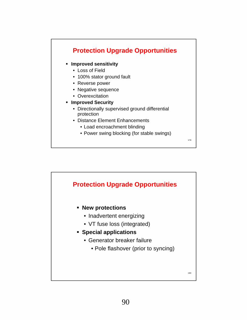
Improved sensitivity• Loss of Field• 100% stator ground fault• Reverse power• Negative sequence• Overexcitation