23
GAS TRAIN EQUIPMENTS CAVAGNA INDUSTRIE
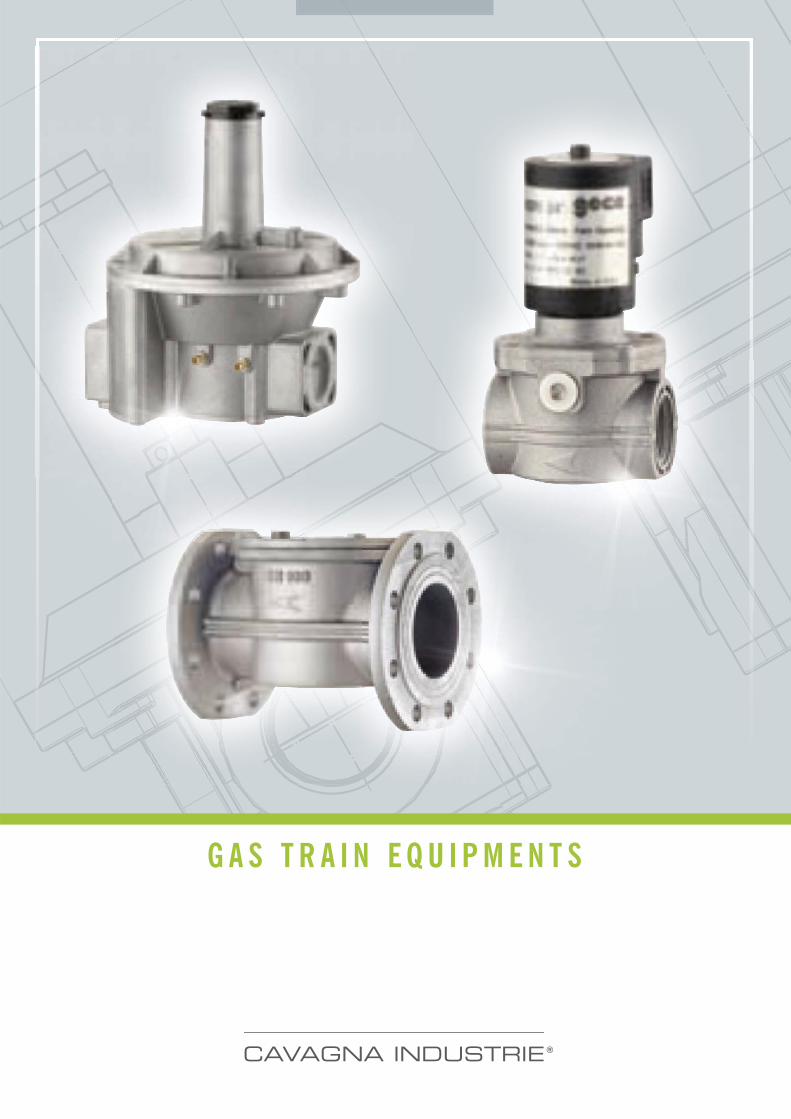
G A S T R A I N E Q U I P M E N T S
CAVAGNA INDUSTRIE


We believe in Quality, we contribute to increase the Italian Technology
and the Style that countersigns the excellence of Italy all over the world.
CAVAGNA INDUSTRIE
CAVAGNA INDUSTRIE
CAVAGNA INDUSTRIE
Gas Governors�� Spring-loaded governors, are designed and built
according UNI EN 88 class A - group 2 specifications,
can be used for all the types of natural gas LPG or not
corrosive gases. These regulators are widely used in
supply lines for mixed and combinated burners and
in the piped distribution of methane gas and LPG
in both industrial and non-industrial applications.
Spring-loaded/ governors are self-acting type with
balanced obturator and double safety diaphragm. The
double diaphragm allow to use the device within the
cabinet, without connecting an external pipe venting.
(Point 3.3.2 of UNI EN 88 regulation). All regulators
have internal sensing line and inlet/outlet pressure
test point.
5
Gas G
over
nors
GasG
over
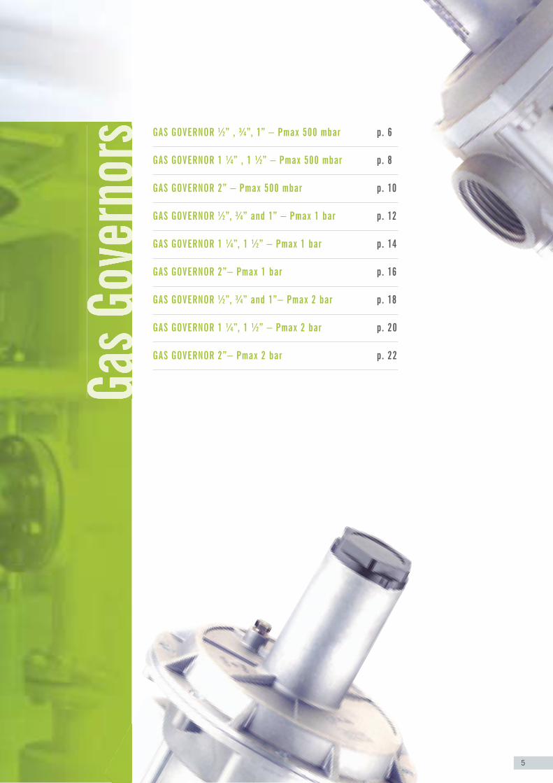
nors GAS GOVERNOR ½” , ¾”, 1” – Pmax 500 mbar p. 6
GAS GOVERNOR 1 ¼” , 1 ½” – Pmax 500 mbar p. 8
GAS GOVERNOR 2” – Pmax 500 mbar p. 10
GAS GOVERNOR ½”, ¾” and 1” – Pmax 1 bar p. 12
GAS GOVERNOR 1 ¼”, 1 ½” – Pmax 1 bar p. 14
GAS GOVERNOR 2”– Pmax 1 bar p. 16
GAS GOVERNOR ½”, ¾” and 1”– Pmax 2 bar p. 18
GAS GOVERNOR 1 ¼”, 1 ½” – Pmax 2 bar p. 20
GAS GOVERNOR 2”– Pmax 2 bar p. 22
6
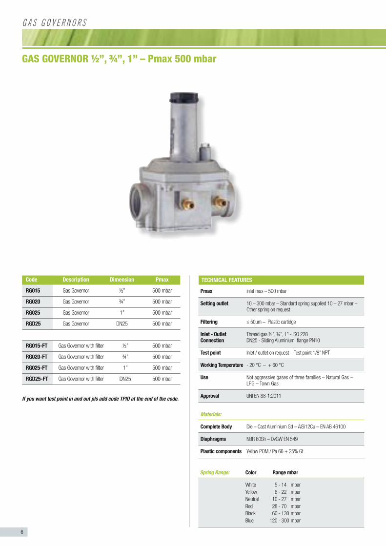
Pmax inlet max – 500 mbar
Setting outlet 10 – 300 mbar – Standard spring supplied 10 – 27 mbar – Other spring on request
Filtering ≤ 50μm – Plastic cartidge
Inlet - Outlet Thread gas ½”, ¾”, 1” - ISO 228Connection DN25 - Sliding Aluminium flange PN10
Test point Inlet / outlet on request – Test point 1/8” NPT
Working Temperature - 20 °C – + 60 °C
Use Not aggressive gases of three families – Natural Gas – LPG – Town Gas
Approval UNI EN 88-1:2011
Materials:
Complete Body Die – Cast Aluminium Gd – AlSi12Cu – EN AB 46100
Diaphragms NBR 60Sh – DvGW EN 549
Plastic components Yellow POM / Pa 66 + 25% Gf
GAS GOVERNOR ½”, ¾”, 1” – Pmax 500 mbar
TECHNICAL FEATURES
G A S G O V E R N O R S
Code Description Dimension Pmax
RG015 Gas Governor ½” 500 mbar
RG020 Gas Governor ¾” 500 mbar
RG025 Gas Governor 1” 500 mbar
RGD25 Gas Governor DN25 500 mbar
RG015-FT Gas Governor with filter ½” 500 mbar
RG020-FT Gas Governor with filter ¾” 500 mbar
RG025-FT Gas Governor with filter 1” 500 mbar
RGD25-FT Gas Governor with filter DN25 500 mbar
If you want test point in and out pls add code TPIO at the end of the code.
Spring Range: Color Range mbar
White 5 - 14 mbar
Yellow 6 - 22 mbar
Neutral 10 - 27 mbar
Red 28 - 70 mbar
Black 60 - 130 mbar
Blue 120 - 300 mbar
7
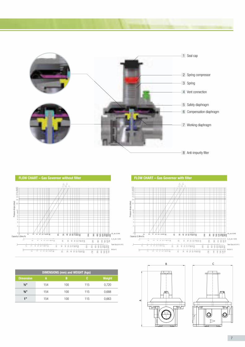
DIMENSIONS (mm) and WEIGHT (kgs)
Dimension A B C Weight
½” 154 100 115 0,720
¾” 154 100 115 0,688
1” 154 100 115 0,663
FLOW CHART – Gas Governor with filterFLOW CHART – Gas Governor without filter
1 Seal cap
2 Spring compressor
3 Spring
4 Vent connection
5 Safety diaphragm
6 Compensation diaphragm
7 Working diaphragm
8 Anti-impurity filter
Pre
ssur
e dr
ops
(mba
r)
CH4 (d=0.544)
C3 H
8 (d=1.522)
Town Gas (d=0.411)
Air (d=1)
CH4 (d=0.544)
C3 H
8 (d=1.522)
Town Gas (d=0.411)
Air (d=1)
Pre
ssur
e dr
ops
(mba
r)
Capacity Q (Nmc/h)Capacity Q (Nmc/h)

8
Pmax inlet max – 500 mbar
Setting outlet 10 – 300 mbar – Standard spring supplied 10 – 27 mbar – Other spring on request
Filtering ≤ 50μm – Viledon cartridge
Inlet - Outlet Thread gas 1 ¼” 1½” - ISO 228Connection DN32 - DN40 - Sliding Aluminium flange PN10
Test point Inlet / outlet on request – Test point 1/8” NPT
Working Temperature - 20 °C – + 60 °C
Use Not aggressive gases of three families – Natural Gas – LPG – Town Gas
Approval UNI EN 88-1:2011
Materials:
Complete Body Die – Cast Aluminium Gd – AlSi12Cu - EN AB 46100
Diaphragms NBR 60Sh – DvGW EN 549
Plastic components White POM / Pa 66 + 25% Gf
GAS GOVERNOR 1 ¼”, 1 ½” – Pmax 500 mbar
TECHNICAL FEATURES
G A S G O V E R N O R S
Code Description Dimension Pmax
RG032 Gas Governor 1 ¼ ” 500 mbar
RG040 Gas Governor 1 ½” 500 mbar
RGD32 Gas Governor DN32 500 mbar
RGD40 Gas Governor DN40 500 mbar
RG032-FT Gas Governor with filter 1 ¼ ” 500 mbar
RG040-FT Gas Governor with filter 1 ½” 500 mbar
RGD32-FT Gas Governor with filter DN32 500 mbar
RGD40-FT Gas Governor with filter DN40 500 mbar
If you want test point in and out pls add code TPIO at the end of the code.
Spring Range: Color Range mbar
White 5 - 14 mbar
Yellow 6 - 22 mbar
Neutral 10 - 27 mbar
Red 28 - 70 mbar
Black 60 - 130 mbar
Blue 120 - 300 mbar

9
FLOW CHART – Gas Governor with filterFLOW CHART – Gas Governor without filter
Pre
ssur
e dr
ops
(mba
r)
Capacity Q (Nmc/h)
CH4 (d=0.544)
C3 H
8 (d=1.522)
Town Gas (d=0.411)
Air (d=1)
CH4 (d=0.544)
C3 H
8 (d=1.522)
Town Gas (d=0.411)
Air (d=1)
Pre
ssur
e dr
ops
(mba
r)
Capacity Q (Nmc/h)
1 Seal cap
2 Spring compressor
3 Spring
4 Vent connection
5 Safety diaphragm
6 Compensation diaphragm
7 Working diaphragm
9 Anti-impurity filter
DIMENSIONS (mm) and WEIGHT (kgs)
Dimension A B C D Weight
1 ¼” 243.5 195.5 206 194 3,140
1 ½” 243.5 195.5 206 194 3,060
8 Sensing tube
10
Spring Range: Color Range mbar
White 5 - 14 mbar
Yellow 6 - 22 mbar
Neutral 10 - 27 mbar
Red 28 - 70 mbar
Black 60 - 130 mbar
Blue 120 - 300 mbar
Pmax inlet max – 500 mbar
Setting outlet 10 – 300 mbar – Standard spring supplied 10 – 27 mbar – Other spring on request
Filtering ≤ 50μm – Viledon cartridge
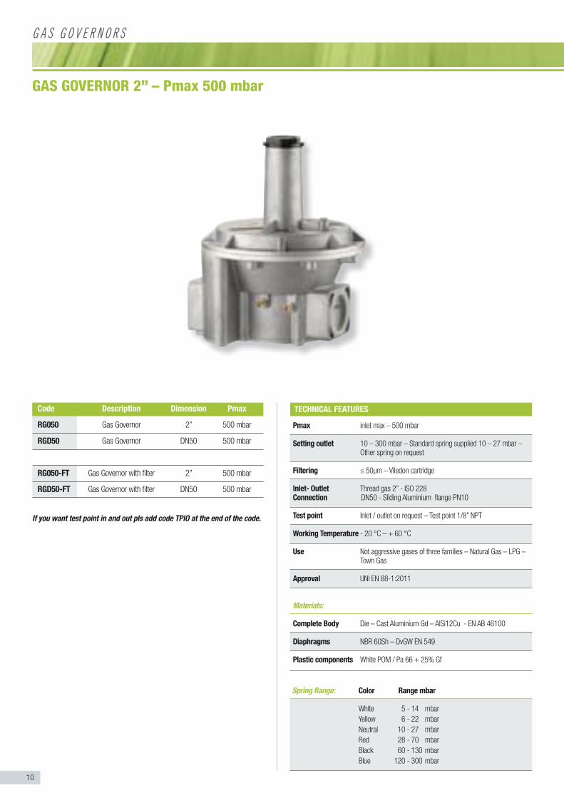
Inlet- Outlet Thread gas 2” - ISO 228Connection DN50 - Sliding Aluminium flange PN10
Test point Inlet / outlet on request – Test point 1/8” NPT
Working Temperature - 20 °C – + 60 °C
Use Not aggressive gases of three families – Natural Gas – LPG – Town Gas
Approval UNI EN 88-1:2011
Materials:
Complete Body Die – Cast Aluminium Gd – AlSi12Cu - EN AB 46100
Diaphragms NBR 60Sh – DvGW EN 549
Plastic components White POM / Pa 66 + 25% Gf
GAS GOVERNOR 2” – Pmax 500 mbar
TECHNICAL FEATURES
G A S G O V E R N O R S
Code Description Dimension Pmax
RG050 Gas Governor 2” 500 mbar
RGD50 Gas Governor DN50 500 mbar
RG050-FT Gas Governor with filter 2” 500 mbar
RGD50-FT Gas Governor with filter DN50 500 mbar
If you want test point in and out pls add code TPIO at the end of the code.

11
FLOW CHART – Gas Governor with filterFLOW CHART – Gas Governor without filter
Pre
ssur
e dr
ops
(mba
r)
Capacity Q (Nmc/h)
CH4 (d=0.544)
C3 H
8 (d=1.522)
Town Gas (d=0.411)
Air (d=1)
CH4 (d=0.544)
C3 H
8 (d=1.522)
Town Gas (d=0.411)
Air (d=1)
Pre
ssur
e dr
ops
(mba
r)
Capacity Q (Nmc/h)
1 Seal cap
2 Spring compressor
3 Spring
4 Vent connection
5 Safety diaphragm
6 Compensation diaphragm
7 Working diaphragm
DIMENSIONS (mm) and WEIGHT (kgs)
Dimension A B C D Weight
2” 301 245 264 235 5,8
9 Anti-impurity filter
8 Sensing tube
12
Spring Range: Color Range mbar
White 5 - 14 mbar
Yellow 6 - 22 mbar
Neutral 10 - 27 mbar
Red 28 - 70 mbar
Black 60 - 130 mbar
Blue 120 - 300 mbar
Pmax inlet max – 500 mbar
Setting outlet 10 – 300 mbar – Standard spring supplied 10 – 27 mbar – Other spring on request
Filtering ≤ 50μm –
Inlet - Outlet Thread gas ½” , ¾” 1” - ISO 228Connection DN25 - Sliding Aluminium flange PN10
Test point Inlet / outlet on request – Test point 1/8” NPT
Working Temperature - 20 °C – + 60 °C
Use Not aggressive gases of three families – Natural Gas – LPG – Town Gas
Approval UNI EN 88-2:2008
Materials:
Complete Body Die – Cast Aluminium Gd – AlSi12Cu - EN AB 46100
Diaphragms NBR 60Sh – DvGW EN 549
Plastic components Yellow POM / Pa 66 + 25% Gf
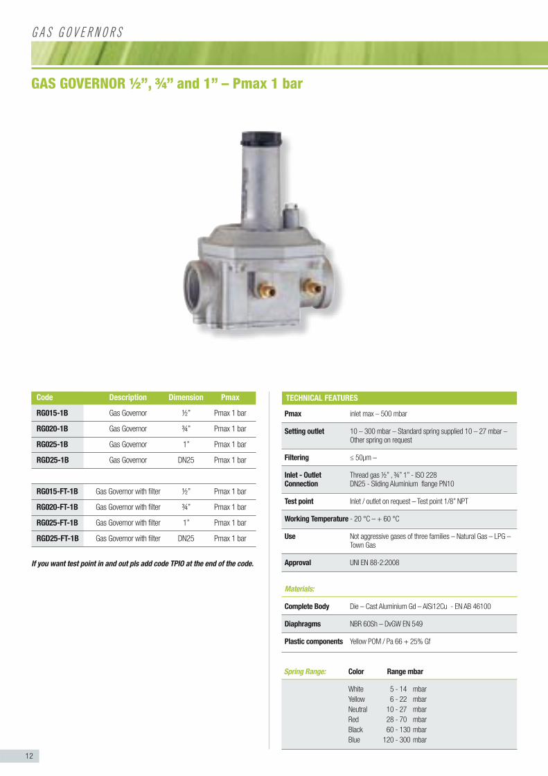
GAS GOVERNOR ½”, ¾” and 1” – Pmax 1 bar
TECHNICAL FEATURES
G A S G O V E R N O R S
Code Description Dimension Pmax
RG015-1B Gas Governor ½” Pmax 1 bar
RG020-1B Gas Governor ¾” Pmax 1 bar
RG025-1B Gas Governor 1” Pmax 1 bar
RGD25-1B Gas Governor DN25 Pmax 1 bar
RG015-FT-1B Gas Governor with filter ½” Pmax 1 bar
RG020-FT-1B Gas Governor with filter ¾” Pmax 1 bar
RG025-FT-1B Gas Governor with filter 1” Pmax 1 bar
RGD25-FT-1B Gas Governor with filter DN25 Pmax 1 bar
If you want test point in and out pls add code TPIO at the end of the code.

13
1 Seal cap
2 Spring compressor
3 Spring
4 Vent connection
5 Safety diaphragm
6 Compensation diaphragm
7 Working diaphragm
8 Anti-impurity filter
DIMENSIONS (mm) and WEIGHT (kgs)
Dimension A B C Weight
½” 154 100 115 0,720
¾” 154 100 115 0,688
1” 154 100 115 0,663
FLOW CHART – Gas Governor with filterFLOW CHART – Gas Governor without filter
Pre
ssur
e dr
ops
(mba
r)
CH4 (d=0.544)
C3 H
8 (d=1.522)
Town Gas (d=0.411)
Air (d=1)
CH4 (d=0.544)
C3 H
8 (d=1.522)
Town Gas (d=0.411)
Air (d=1)
Pre
ssur
e dr
ops
(mba
r)
Capacity Q (Nmc/h)Capacity Q (Nmc/h)
14
Spring Range: Color Range mbar
White 5 - 14 mbar
Yellow 6 - 22 mbar
Neutral 10 - 27 mbar
Red 28 - 70 mbar
Black 60 - 130 mbar
Blue 120 - 300 mbar
Pmax inlet max – 1 bar
Setting outlet 10 – 300 mbar – Standard spring supplied 10 – 27 mbar – Other spring on request
Filtering ≤ 50μm – Viledon cartridge
Inlet - Outlet Thread gas 1 ¼” 1½” - ISO 228Connection DN32 DN40 - Sliding Aluminium flange PN10
Test point Inlet / outlet on request – Test point 1/8” NPT
Working Temperature - 20 °C – + 60 °C
Use Not aggressive gases of three families – Natural Gas – LPG – Town Gas
Approval UNI EN 88-2:2008
Materials:
Complete Body Die – Cast Aluminium Gd – AlSi12Cu - EN AB 46100
Diaphragms NBR 60Sh – DvGW EN 549
Plastic components White POM / Pa 66 + 25% Gf
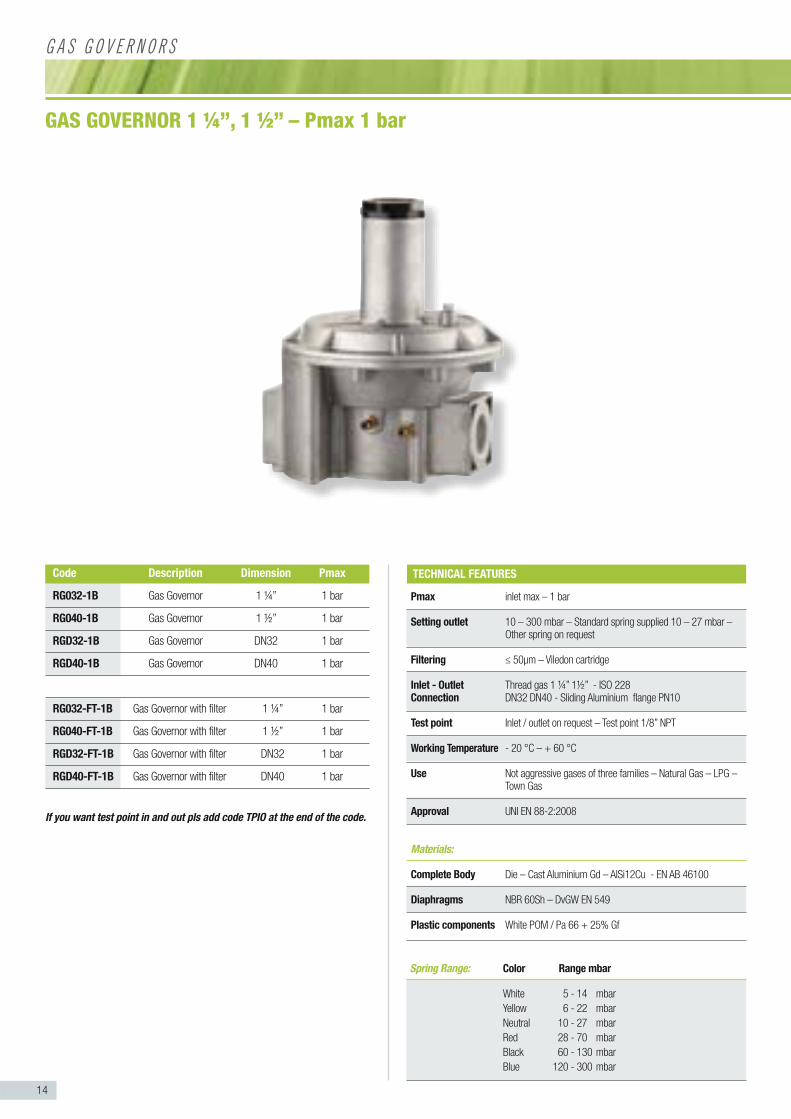
GAS GOVERNOR 1 ¼”, 1 ½” – Pmax 1 bar
TECHNICAL FEATURES
G A S G O V E R N O R S
Code Description Dimension Pmax
RG032-1B Gas Governor 1 ¼” 1 bar
RG040-1B Gas Governor 1 ½” 1 bar
RGD32-1B Gas Governor DN32 1 bar
RGD40-1B Gas Governor DN40 1 bar
RG032-FT-1B Gas Governor with filter 1 ¼” 1 bar
RG040-FT-1B Gas Governor with filter 1 ½” 1 bar
RGD32-FT-1B Gas Governor with filter DN32 1 bar
RGD40-FT-1B Gas Governor with filter DN40 1 bar
If you want test point in and out pls add code TPIO at the end of the code.

15
FLOW CHART – Gas Governor with filterFLOW CHART – Gas Governor without filter
1 Seal cap
2 Spring compressor
3 Spring
4 Vent connection
5 Safety diaphragm
6 Compensation diaphragm
7 Working diaphragm
Pre
ssur
e dr
ops
(mba
r)
Capacity Q (Nmc/h)
CH4 (d=0.544)
C3 H
8 (d=1.522)
Town Gas (d=0.411)
Air (d=1)
CH4 (d=0.544)
C3 H
8 (d=1.522)
Town Gas (d=0.411)
Air (d=1)
Pre
ssur
e dr
ops
(mba
r)
Capacity Q (Nmc/h)
DIMENSIONS (mm) and WEIGHT (kgs)
Dimension A B C D Weight
1 ¼” 243.5 195.5 206 194 3,140
1 ½” 243.5 195.5 206 194 3,060
9 Anti-impurity filter
8 Sensing tube
16
Spring Range: Color Range mbar
White 5 - 14 mbar
Yellow 6 - 22 mbar
Neutral 10 - 27 mbar
Red 28 - 70 mbar
Black 60 - 130 mbar
Blue 120 - 300 mbar
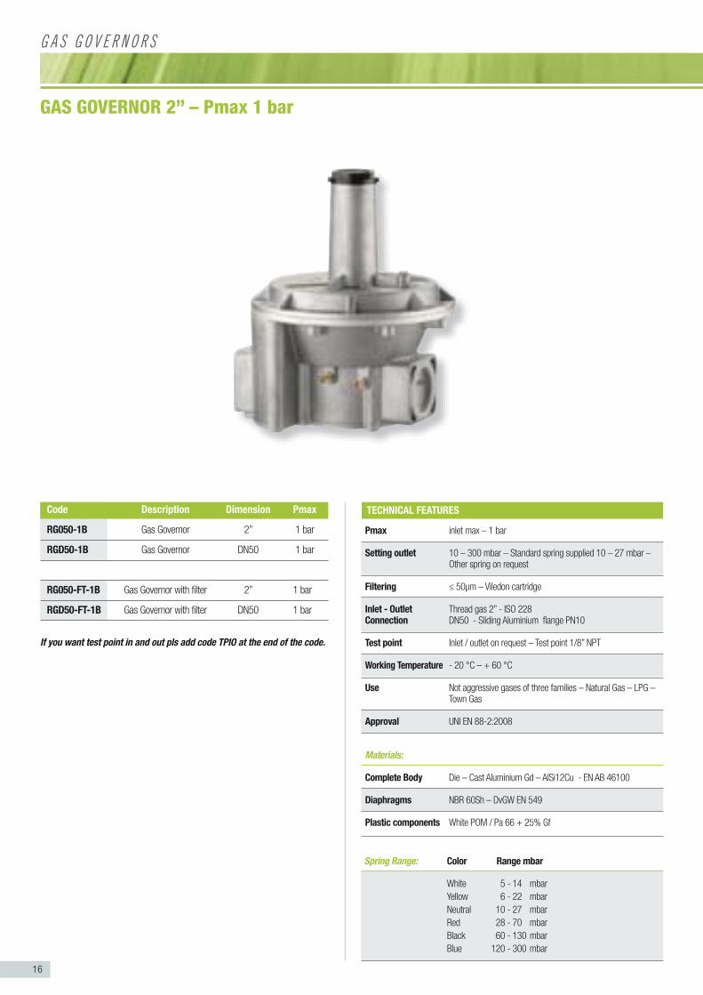
Pmax inlet max – 1 bar
Setting outlet 10 – 300 mbar – Standard spring supplied 10 – 27 mbar – Other spring on request
Filtering ≤ 50μm – Viledon cartridge
Inlet - Outlet Thread gas 2” - ISO 228Connection DN50 - Sliding Aluminium flange PN10
Test point Inlet / outlet on request – Test point 1/8” NPT
Working Temperature - 20 °C – + 60 °C
Use Not aggressive gases of three families – Natural Gas – LPG – Town Gas
Approval UNI EN 88-2:2008
Materials:
Complete Body Die – Cast Aluminium Gd – AlSi12Cu - EN AB 46100
Diaphragms NBR 60Sh – DvGW EN 549
Plastic components White POM / Pa 66 + 25% Gf
GAS GOVERNOR 2” – Pmax 1 bar
TECHNICAL FEATURES
G A S G O V E R N O R S
Code Description Dimension Pmax
RG050-1B Gas Governor 2” 1 bar
RGD50-1B Gas Governor DN50 1 bar
RG050-FT-1B Gas Governor with filter 2” 1 bar
RGD50-FT-1B Gas Governor with filter DN50 1 bar
If you want test point in and out pls add code TPIO at the end of the code.
17
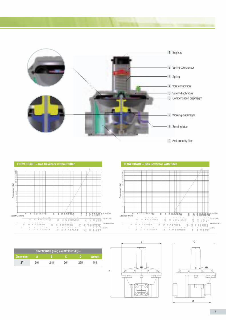
1 Seal cap
2 Spring compressor
3 Spring
4 Vent connection
5 Safety diaphragm
6 Compensation diaphragm
7 Working diaphragm
FLOW CHART – Gas Governor with filterFLOW CHART – Gas Governor without filter
Pre
ssur
e dr
ops
(mba
r)
Capacity Q (Nmc/h)
CH4 (d=0.544)
C3 H
8 (d=1.522)
Town Gas (d=0.411)
Air (d=1)
CH4 (d=0.544)
C3 H
8 (d=1.522)
Town Gas (d=0.411)
Air (d=1)
Pre
ssur
e dr
ops
(mba
r)
Capacity Q (Nmc/h)
DIMENSIONS (mm) and WEIGHT (kgs)
Dimension A B C D Weight
2” 301 245 264 235 5,8
9 Anti-impurity filter
8 Sensing tube

18
Spring Range: Color Range mbar
White 5 - 14 mbar
Yellow 6 - 22 mbar
Neutral 10 - 27 mbar
Red 28 - 70 mbar
Black 60 - 130 mbar
Blue 120 - 300 mbar
Pmax inlet max – 2 bar
Setting outlet 10 – 300 mbar – Standard spring supplied 10 – 27 mbar – Other spring on request
Filtering ≤ 50μm –
Inlet - Outlet Thread gas ½” , ¾” 1” - ISO 228Connection DN25 - Sliding Aluminium flange PN10
Test point Inlet / outlet on request – Test point 1/8” NPT
Working Temperature - 20 °C – + 60 °C
Use Not aggressive gases of three families – Natural Gas – LPG – Town Gas
Approval UNI EN 88-2:2008
Materials:
Complete Body Die – Cast Aluminium Gd – AlSi12Cu - EN AB 46100
Diaphragms NBR 60Sh – DvGW EN 549
Plastic components Yellow POM / Pa 66 + 25% Gf
GAS GOVERNOR ½”, ¾” and 1”– Pmax 2 bar
TECHNICAL FEATURES
G A S G O V E R N O R S
Code Description Dimension Pmax
RG015-2B Gas Governor ½” Pmax 2 bar
RG020-2B Gas Governor ¾” Pmax 2 bar
RG025-2B Gas Governor 1” Pmax 2 bar
RGD25-2B Gas Governor 1” Pmax 2 bar
RG032-2B Gas Governor with filter 1 ¼ ” 500 mbar
RG040-2B Gas Governor with filter 1 ½” 500 mbar
RGD32-2B Gas Governor with filter DN32 500 mbar
RGD40-2B Gas Governor with filter DN40 500 mbar
If you want test point in and out pls add code TPIO at the end of the code.

19
1 Seal cap
2 Spring compressor
3 Spring
4 Vent connection
5 Safety diaphragm
6 Compensation diaphragm
7 Working diaphragm
8 Anti-impurity filter
FLOW CHART – Gas Governor with filterFLOW CHART – Gas Governor without filter
DIMENSIONS (mm) and WEIGHT (kgs)
Dimension A B C Weight
½” 154 100 115 0,720
¾” 154 100 115 0,688
1” 154 100 115 0,663
Pre
ssur
e dr
ops
(mba
r)
CH4 (d=0.544)
C3 H
8 (d=1.522)
Town Gas (d=0.411)
Air (d=1)
CH4 (d=0.544)
C3 H
8 (d=1.522)
Town Gas (d=0.411)
Air (d=1)
Pre
ssur
e dr
ops
(mba
r)
Capacity Q (Nmc/h)Capacity Q (Nmc/h)
20
Spring Range: Color Range mbar
White 5 - 14 mbar
Yellow 6 - 22 mbar
Neutral 10 - 27 mbar
Red 28 - 70 mbar
Black 60 - 130 mbar
Blue 120 - 300 mbar
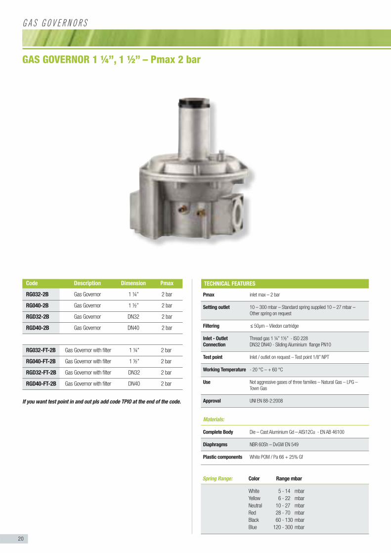
Pmax inlet max – 2 bar
Setting outlet 10 – 300 mbar – Standard spring supplied 10 – 27 mbar –
Other spring on request
Filtering ≤ 50μm – Viledon cartridge
Inlet - Outlet Thread gas 1 ¼” 1½” - ISO 228
Connection DN32 DN40 - Sliding Aluminium flange PN10
Test point Inlet / outlet on request – Test point 1/8” NPT
Working Temperature - 20 °C – + 60 °C
Use Not aggressive gases of three families – Natural Gas – LPG –
Town Gas
Approval UNI EN 88-2:2008
Materials:
Complete Body Die – Cast Aluminium Gd – AlSi12Cu - EN AB 46100
Diaphragms NBR 60Sh – DvGW EN 549
Plastic components White POM / Pa 66 + 25% Gf
GAS GOVERNOR 1 ¼”, 1 ½” – Pmax 2 bar
TECHNICAL FEATURES
G A S G O V E R N O R S
Code Description Dimension Pmax
RG032-2B Gas Governor 1 ¼” 2 bar
RG040-2B Gas Governor 1 ½” 2 bar
RGD32-2B Gas Governor DN32 2 bar
RGD40-2B Gas Governor DN40 2 bar
RG032-FT-2B Gas Governor with filter 1 ¼” 2 bar
RG040-FT-2B Gas Governor with filter 1 ½” 2 bar
RGD32-FT-2B Gas Governor with filter DN32 2 bar
RGD40-FT-2B Gas Governor with filter DN40 2 bar
If you want test point in and out pls add code TPIO at the end of the code.
21
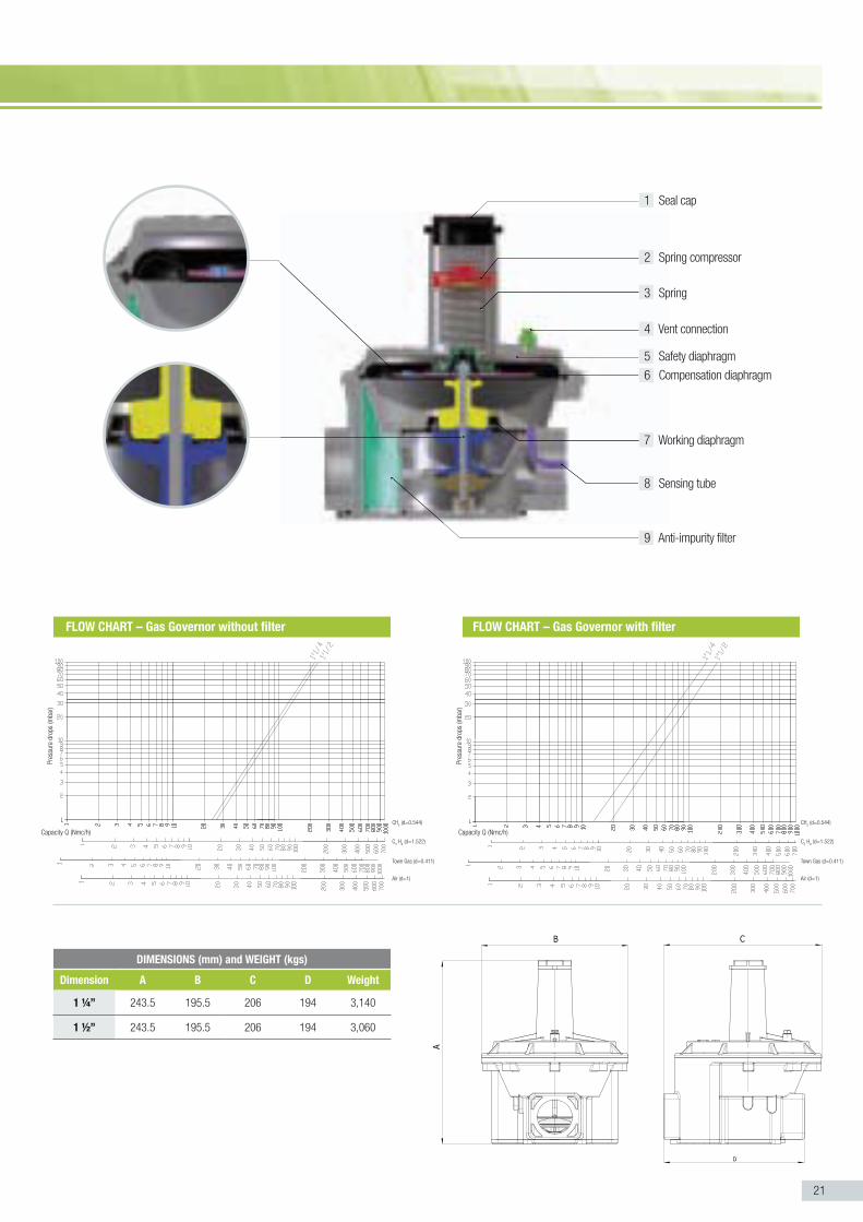
FLOW CHART – Gas Governor with filterFLOW CHART – Gas Governor without filter
1 Seal cap
2 Spring compressor
3 Spring
4 Vent connection
5 Safety diaphragm
6 Compensation diaphragm
7 Working diaphragm
Pre
ssur
e dr
ops
(mba
r)
Capacity Q (Nmc/h)
CH4 (d=0.544)
C3 H
8 (d=1.522)
Town Gas (d=0.411)
Air (d=1)
CH4 (d=0.544)
C3 H
8 (d=1.522)
Town Gas (d=0.411)
Air (d=1)
Pre
ssur
e dr
ops
(mba
r)
Capacity Q (Nmc/h)
DIMENSIONS (mm) and WEIGHT (kgs)
Dimension A B C D Weight
1 ¼” 243.5 195.5 206 194 3,140
1 ½” 243.5 195.5 206 194 3,060
9 Anti-impurity filter
8 Sensing tube

22
Spring Range: Color Range mbar
White 5 - 14 mbar
Yellow 6 - 22 mbar
Neutral 10 - 27 mbar
Red 28 - 70 mbar
Black 60 - 130 mbar
Blue 120 - 300 mbar
Pmax inlet max – 2 bar
Setting outlet 10 – 300 mbar – Standard spring supplied 10 – 27 mbar – Other spring on request
Filtering ≤ 50μm – Viledon cartridge
Inlet - Outlet Thread gas 2” - ISO 228Connection DN50 - Sliding Aluminium flange PN10
Test point Inlet / outlet on request – Test point 1/8” NPT
Working Temperature - 20 °C – + 60 °C
Use Not aggressive gases of three families – Natural Gas – LPG – Town Gas
Approval UNI EN 88-2:2008
Materials:
Complete Body Die – Cast Aluminium Gd – AlSi12Cu - EN AB 46100
Diaphragms NBR 60Sh – DvGW EN 549
Plastic components White POM / Pa 66 + 25% Gf
GAS GOVERNOR 2”– Pmax 2 bar
TECHNICAL FEATURES
G A S G O V E R N O R S
Code Description Dimension Pmax
RG050-2B Gas Governor 2” 2 bar
RGD50-2B Gas Governor DN50 2 bar
RG050-FT-2B Gas Governor with filter 2” 2 bar
RGD50-FT-2B Gas Governor with filter DN50 2 bar
If you want test point in and out pls add code TPIO at the end of the code.

23
1 Seal cap
2 Spring compressor
3 Spring
4 Vent connection
5 Safety diaphragm
6 Compensation diaphragm
7 Working diaphragm
FLOW CHART – Gas Governor with filterFLOW CHART – Gas Governor without filter
Pre
ssur
e dr
ops
(mba
r)
Capacity Q (Nmc/h)
CH4 (d=0.544)
C3 H
8 (d=1.522)
Town Gas (d=0.411)
Air (d=1)
CH4 (d=0.544)
C3 H
8 (d=1.522)
Town Gas (d=0.411)
Air (d=1)
Pre
ssur
e dr
ops
(mba
r)
Capacity Q (Nmc/h)
DIMENSIONS (mm) and WEIGHT (kgs)
Dimension A B C D Weight
2” 301 245 264 235 5,8
9 Anti-impurity filter
8 Sensing tube


