26

Gaussian Minimum Shift Keying(GMSK) Modulation and Demodulation
Boddu Naresh Goud
EE10B006
May 17, 2014
Prof. David Koilpillai
Department of Electrical Engineering
IIT Madras

Contents
1 Introduction 4
1.1 Motivation . . . . . . . . . . . . . . . . . . . . . . . . . . . . . . . . . . . . 41.2 Organization of the thesis . . . . . . . . . . . . . . . . . . . . . . . . . . . 4
2 GMSK and its Laurent representation 5
2.1 GMSK . . . . . . . . . . . . . . . . . . . . . . . . . . . . . . . . . . . . . . 52.2 GMSK Modulation . . . . . . . . . . . . . . . . . . . . . . . . . . . . . . . 62.3 Laurent representation of Continous Pulse Modulation(CPM) . . . . . . . 82.4 GMSK BT=0.3, L=3 Laurent representation . . . . . . . . . . . . . . . . 92.5 AWGN Channel . . . . . . . . . . . . . . . . . . . . . . . . . . . . . . . . . 10
3 GMSK Demodulator for BT=0.5 11
3.1 Demodulator . . . . . . . . . . . . . . . . . . . . . . . . . . . . . . . . . . 123.2 Plot for BER Vs SNR(db) . . . . . . . . . . . . . . . . . . . . . . . . . . . 13
4 GMSK Demodulator for BT=0.3 14
4.1 Symbol by symbol detection(Without Viterbi) . . . . . . . . . . . . . . . . 154.2 Plot for BER Vs SNR(db) for BT=0.3 without Viterbi. . . . . . . . . . . . 164.3 MLSE using Viterbi Decoding for BT=0.3 . . . . . . . . . . . . . . . . . . 16
4.3.1 Estimating h0, h1, h2: . . . . . . . . . . . . . . . . . . . . . . . . . . 194.4 Plot for BER Vs SNR(db) for BT=0.3 using Viterbi Algorithm. . . . . . . 20
5 GMSK Demodulation in �at fading 21
5.1 Plot for BER Vs SNR(db) for BT=0.5 . . . . . . . . . . . . . . . . . . . . 215.2 Plot for BER Vs SNR(db) for BT=0.3 using Viterbi . . . . . . . . . . . . 22
6 GMSK Demodulation in multipath fading 23
7 Conclusion 24
2
Abstract
This Report discusses the implementation of Gaussian Minimum Shift Keying (GMSK)Modulation and Demodulation Schemes using Symbol by Symbol detection and Viterbidecoding. GMSK is most prominent standards around the world. Global System forMobile communication (GSM), Digital European Cordless Telephone (DECT), Cellu-lar Digital Packet Data (CDPD), Digital communications system in the 1800 MHzband (DCS1800 in Europe), Personal communications services in the 1900 MHz band(PCS1900) in U.S., all use GMSK as their modulation format. The reason GMSK is usedfor GSM is its High spectral e�ciency, MSK uses phase variation for modulation so betterimmune to noise. Non linear ampli�ers are used to give better response and consumesless power so low battery usage which is an important parameter in cellular technologies.Gaussian Minimum Shift keying modulation scheme is a derivative of MSK. In GMSK,the side lobe levels of the spectrum introduced in MSK are further reduced by passingthe modulating NRZ data waveform through a pre modulation Gaussian pulse-shaping�lter. ISI degrade the performance of GMSK. GMSK performance is improved by usingoptimum �lters, soft decision Viterbi decoding.Index Terms� Bit Error Rate (BER), Gaussian �lter, Gaussian Minimum Shift Keying
(GMSK), Inter Symbol Interference (ISI), Minimum Shift Keying (MSK), Signal to NoiseRatio (SNR).
3

1 Introduction
1.1 Motivation
The need for people to communicate with each other anytime, anywhere has greatlyexpanded the �eld of wireless communication. Due to user's demands for more andbetter wireless services, there is a need for higher transmission bandwidth. However,in a wireless communication system, adding bandwidth is not as easy as in a wire-line system. As a result, spectral congestion becomes a serious problem. Spectrallye�cient modulation scheme, which maximize the bandwidth e�ciency, is a very promisingsolution. To achieve spectral e�ciency, certain modulation constraints are imposed,which lead to a more complex receiver design. wireless communication becomes morepopular, there is also a big demand for a more compact receiver. Therefore, there is aneed to reduce the complexity of the receiver structures without losing much performance.Gaussian Minimum Shift Keying(GMSK) is a spectrum and power e�cient modula-
tion scheme, used in many wireless communication systems. The GSM cellular, CellularDigital Packet Data (CDPD) and Mobitex standards are some of the best known usesof GMSK. However, because of the phase modulation and Gaussian �ltering, GMSK isnot a linear modulation scheme. It is well known that the receiver structure for a linearmodulation scheme(e.g. Pulse Amplitude Modulation) is less complex than that for thenonlinear modulation scheme.The goal of this thesis is to attempt to reduce the complex-ity of GMSK receiver by using a linear approximation of GMSK and coherent detection.The reduction in demodulation cornplexity is achicved by using the Laurent represcnta-tion of GMSK. The Laurent representation decomposes Continuous Phase Modulation(CPM) signals into summations of PAM signals. It has been successfully implementedin [1], [3] to reduce the complexity of coherent CPM receivers.
1.2 Organization of the thesis
Chapter 2 presents a brief tutorial on GMSK, the Laurent representation, AWGN chan-nel. Chapter 3 describes the design of simple coherent GMSK receiver for BT=0.5 basedon Laurent representation. It's performance in the AWGN channel will be comparedto a corresponding coherent MSK receiver. Chapter 4 describes the design of reduced-complexity coherent GMSK receiver for BT=0.3 based on Laurent representation. It'sperformance in the AWGN channel will be compared to a corresponding coherent MSKreceiver.Chapter 5 describes the design of coherent GMSK receiver in �at fading chan-nel.Chapter 6 provides a summary and conclusions of this thesis along with suggestionsfor further research.
4

2 GMSK and its Laurent representation
2.1 GMSK
Gaussian Minimum Shift Keying belongs to the class of CPM schemes CPM is a modula-tion scheme in which the phase of the carrier is instantaneously varied by the modulatingsignal while the RF signal envelope is kept constant. Due to the constant envelope, theCPM signals are not sensitive to ampli�er nonlinearities, which results in a more compactpower spectrum.The Baseband GMSK signal can be represented as
s(t) = exp(j ∗ ϕ(t, α))
. ϕ(t, α) is the Phase of the signal given by
ϕ(t, α) = pi ∗ h ∗tˆ
−inf
(i=n∑i=0
α[i]g(t− iT ))
The Phase can be written as
ϕ(t, α) = pi ∗ h ∗i=n∑i=0
α[i]q(t− i ∗ T )
where
q(t) =
tˆ
−inf
g(τ)dτ
g(t)is the impulse response of the premodulation �lter given by
g(t) = B
√2pi
ln(2)exp[−2pi2B2t2
ln(2)]
.Bis the 3db bandwidth of the �lter.By convention, B is normally expressed in terrns of
the inverse of T; therefore the 3-dB bandwidth of �lter is de�ned as BT. The frequencypulse g(t) for GMSK is :
g(t) =1
2T{Q(2pi ∗B
(t− T2 )√
ln2)−Q(2pi ∗B
(t+ T2 )√
ln2)}
5
where
Q(t) =
ˆ inf
t
1√2pi
exp(−τ2
2)dτ
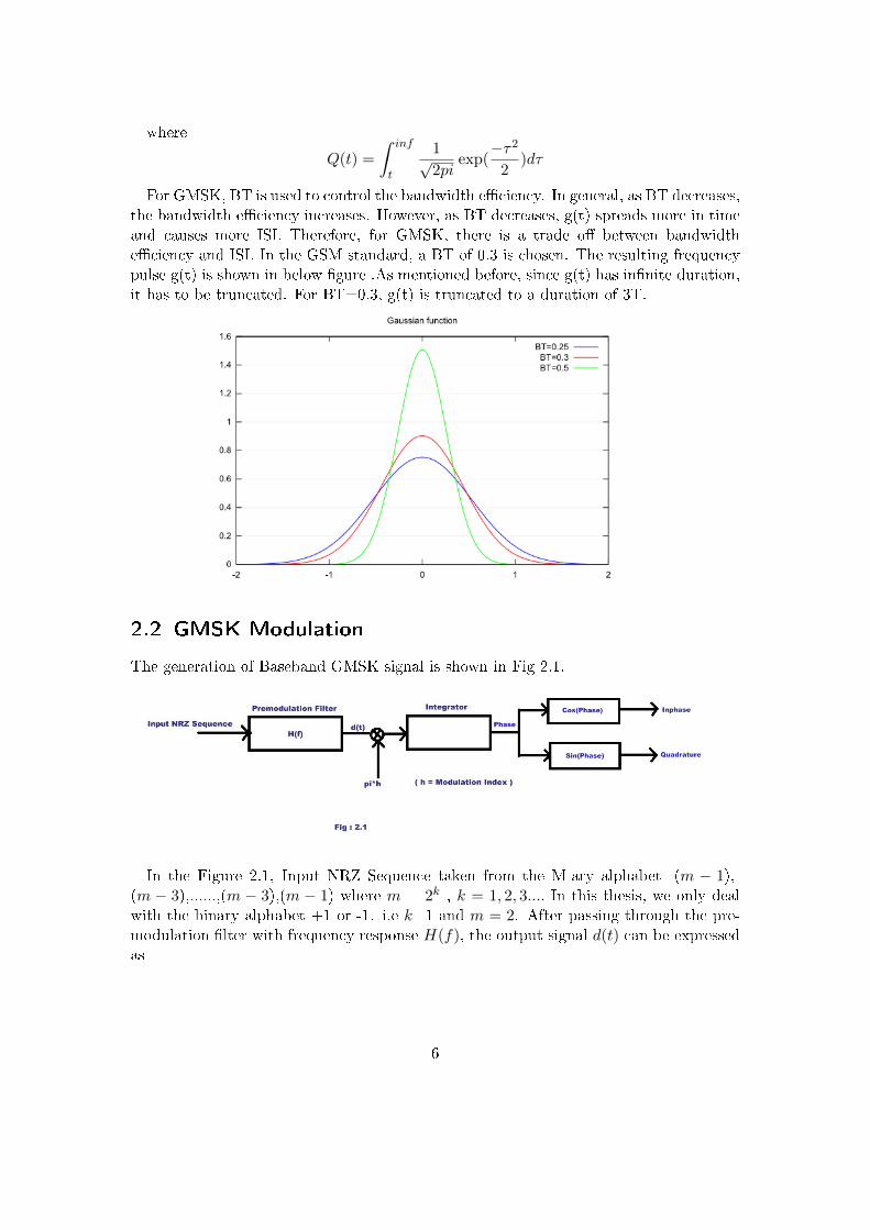
For GMSK, BT is used to control the bandwidth e�ciency. In general, as BT decreases,the bandwidth e�ciency increases. However, as BT decreases, g(t) spreads more in timeand causes more ISI. Therefore, for GMSK, there is a trade o� between bandwidthe�ciency and ISI. In the GSM standard, a BT of 0.3 is chosen. The resulting frequencypulse g(t) is shown in below �gure .As mentioned before, since g(t) has in�nite duration,it has to be truncated. For BT=0.3, g(t) is truncated to a duration of 3T.
2.2 GMSK Modulation
The generation of Baseband GMSK signal is shown in Fig 2.1.
In the Figure 2.1, Input NRZ Sequence taken from the M-ary alphabet -(m − 1),-(m − 3),......,(m − 3),(m − 1) where m = 2k , k = 1, 2, 3.... In this thesis, we only dealwith the binary alphabet +1 or -1. i.e k=1 and m = 2. After passing through the pre-modulation �lter with frequency response H(f), the output signal d(t) can be expressedas
6

d(t) =i=n∑i=0
α[i]g(t− i ∗ T )
g(t) is the gaussian pulse and H(f) is the Gaussian frequency response.
g(t) =1
2T{Q(2pi ∗B
(t− T2 )√
ln2)−Q(2pi ∗B
(t+ T2 )√
ln2)}
where
Q(t) =
ˆ inf
t
1√2pi
exp(−τ2
2)dτ
and
H(f) = exp(− ln 2
2B2f2)
α[i] is the Input NRZ Sequence .h is modulation index. For GMSK h = 1
2 .The resulting signal d(t)is passed through a Integrator to get the phase of the signal.
Phase of the signal can be written as
ϕ(t, α) = pi ∗ h ∗ˆ t=t
t=−inf
i=n∑i=0
α[i]g(t− i ∗ T )
The Phase can be written as
ϕ(t, α) = pi ∗ h ∗i=n∑i=0
α[i]q(t− i ∗ T )
where
q(t) =
tˆ
−inf
g(τ)dτ
.The In-phase component of the baseband representation is the Cosine of the phase
generated and the Quadrature component of the baseband representation is the Sine ofthe phase generated.
I = cos(ϕ(t, α))
Q = sin(ϕ(t, α))
s(t) = I + j ∗Q
7

2.3 Laurent representation of Continous PulseModulation(CPM)
In baseband, CPM signals can be represented as s(t) = exp(j ∗ ϕ(t, α)), where
ϕ(t, α) = pi ∗ h ∗i=n∑i=0
α[i]q(t− i ∗ T )
. For nT< t < nT + T, we have
s(t) = exp(jpi ∗ hi=n−L∑i=0
α[i])i=n∏
i=n−L+1
exp[j ∗ h ∗ pi ∗ α[i] ∗ q(t− iT )] (2.1)
Let J = exp(j ∗ pi ∗ h) , then Jα[i] = cos(pi ∗ h) + jα[i] sin(pi ∗ h).Using this relation,the product terms of (2.1) can be expressed as
exp[j ∗ pi ∗ hα[i]q(t− iT )] = cos(pi ∗ hq(t− iT )) + jα[i] sin(pi ∗ hq(t− iT ))
= Jα[i]sin[pi ∗ hq(t− iT )]
sin(pi ∗ h)+
sin[pi ∗ h− pi ∗ hq(t− iT )]sin(pi ∗ h)
If we also notice that 1− q(t) = q(LT )− q(t) = q(LT − t) and de�ne
C(t) =sin[pi ∗ h− pi ∗ hq(t)]
sin(pi ∗ h): 0 ≤ t ≤ LT
C(t) = C(−t) : 0 ≤ t ≤ LT
a0[n− L] = exp(j ∗ pi ∗ hi=n−L∑i=0
α[i])
we have
s(t) = exp(jpi ∗ hi=n−L∑i=0
α[i])i=n∏
i=n−L+1
exp[j ∗ h ∗ pi ∗ α[i] ∗ q(t− iT )]
= a0[n− L]i=n∏
i=n−L+1
[Jα[i]C(t− iT − LT ) + C(t− iT )] (2.2)
Expanding 2.2 ,Laurent shows that there are only 2L−1 di�erent pulses and each pulseis obtained by the product of L shifted version of C(t) . For binary GMSK(h=0.5.&J=j), it can be shown that the Laurent representation is given by
8

s(t) =2L−1−1∑i=0
n=n∑n=0
ai[n]hi[t− nT ]
where hi[t]terms are the impulse responses of the Laurent PAM pulses and
a0[n] = a0[n− 1] ∗ jα[n]
ai[n] = a0[n− L]∏iεIk
jα[n−i]
Ikis a non empty subset of the set {0,1,2,....,L-1}.
2.4 GMSK BT=0.3, L=3 Laurent representation
For GMSK with BT=0.3 and L=3, s(t) can be represented by 4 PAM signals
s(t) =3∑
k=0
∑n
jnak,nhk[t− nT ]
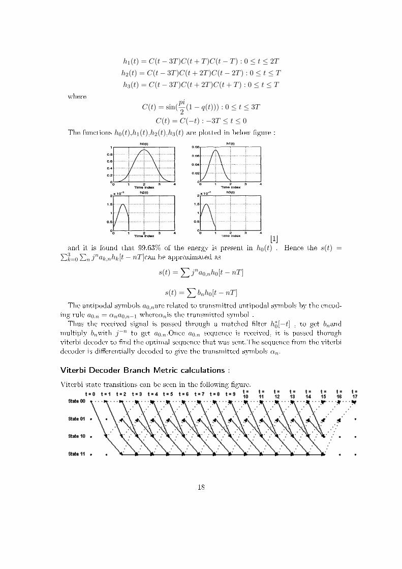
h0(t) = C(t− 3T )C(t− 2T )C(t− T ) : 0 ≤ t ≤ 4T
h1(t) = C(t− 3T )C(t+ T )C(t− T ) : 0 ≤ t ≤ 2T
h2(t) = C(t− 3T )C(t+ 2T )C(t− 2T ) : 0 ≤ t ≤ Th3(t) = C(t− 3T )C(t+ 2T )C(t+ T ) : 0 ≤ t ≤ T
where
C(t) = sin(pi
2(1− q(t))) : 0 ≤ t ≤ 3T
C(t) = C(−t) : −3T ≤ t ≤ 0
The functions h0(t),h1(t),h2(t),h3(t) are plotted in �g 2.2 and it is found that 99.63%of the energy is present in h0(t) . Hence the s(t) =
∑3k=0
∑n j
nak,nhk[t − nT ]can beapproximated as
s(t) =∑
jna0,nh0[t− nT ]
The antipodal symbols a0,nare related to transmitted antipodal symbols by the encod-ing rule a0.n = αna0,n−1
Therefore the Linear approximation of the GMSK Modulator can be represented bythe following �gure:
9
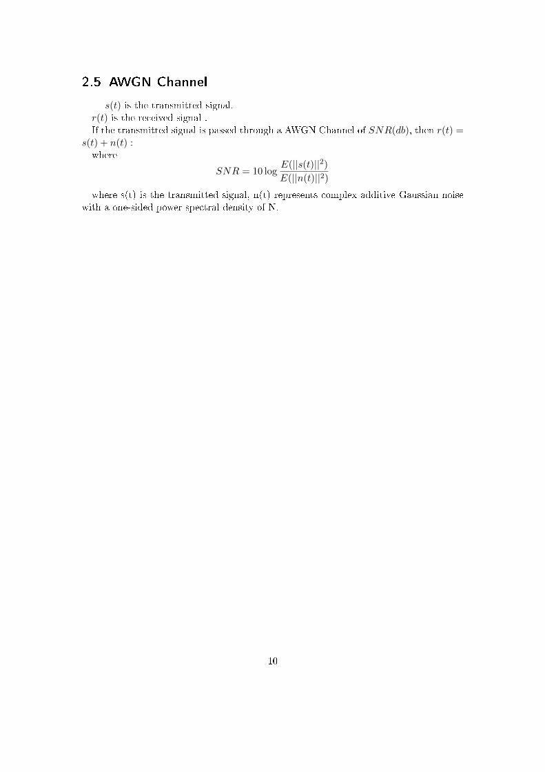
2.5 AWGN Channel
s(t) is the transmitted signal.r(t) is the received signal .If the transmitted signal is passed through a AWGN Channel of SNR(db), then r(t) =
s(t) + n(t) :where
SNR = 10 logE(||s(t)||2)E(||n(t)||2)
where s(t) is the transmitted signal, n(t) represents complex additive Gaussian noisewith a one-sided power spectral density of N.
10
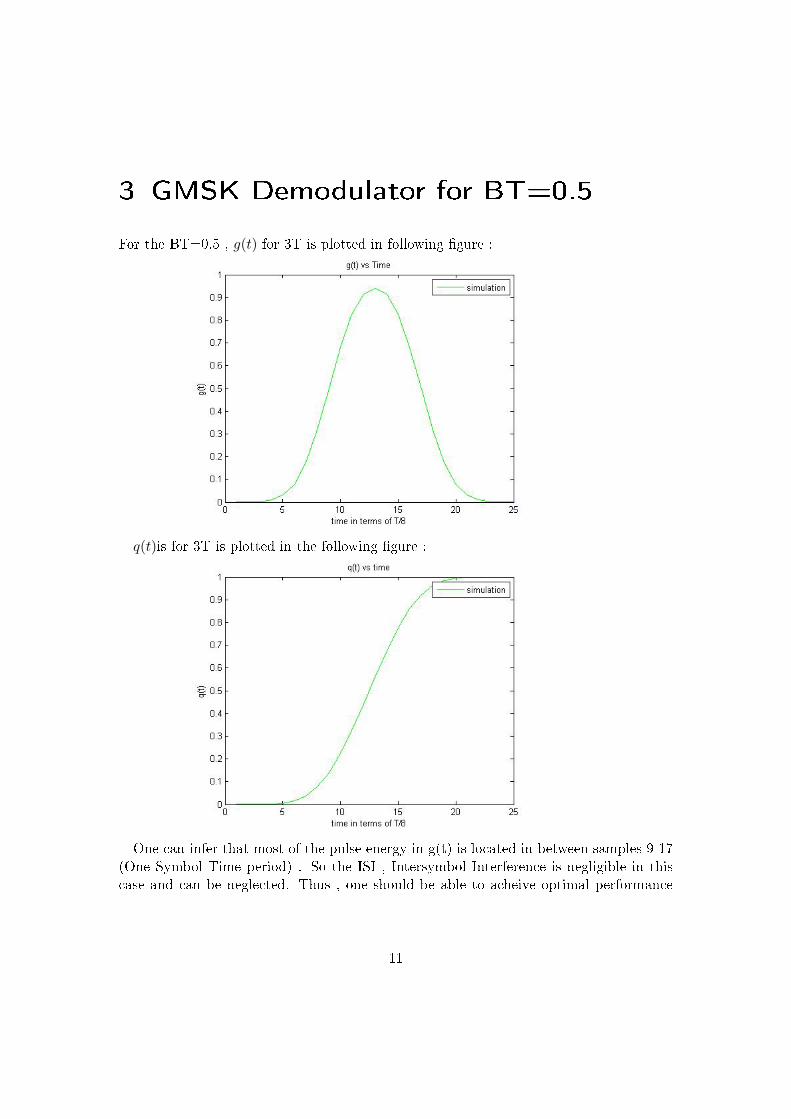
3 GMSK Demodulator for BT=0.5
For the BT=0.5 , g(t) for 3T is plotted in following �gure :
q(t)is for 3T is plotted in the following �gure :
One can infer that most of the pulse energy in g(t) is located in between samples 9-17(One Symbol Time period) . So the ISI , Intersymbol Interference is negligible in thiscase and can be neglected. Thus , one should be able to acheive optimal performance
11

without using Viterbi decoder since there is no ISI.
3.1 Demodulator
Using the Laurent PAM representation of the GMSK , BT = 0.5 ,we can write
s(t) =∑
jna0,nh0[t− nT ]
The antipodal symbols a0,nare related to transmitted antipodal symbols by the encod-ing rule a0.n = αna0,n−1 and bn = a0,nj
n
andr(t) = s(t) + n(t) :
where
SNR(db) = 10 logE(||s(t)||2)E(||n(t)||2)
where s(t) is the transmitted signal, n(t) represents complex additive Gaussian noisewith a one-sided power spectral density of N.Optimum Demodulator Figure is :
12
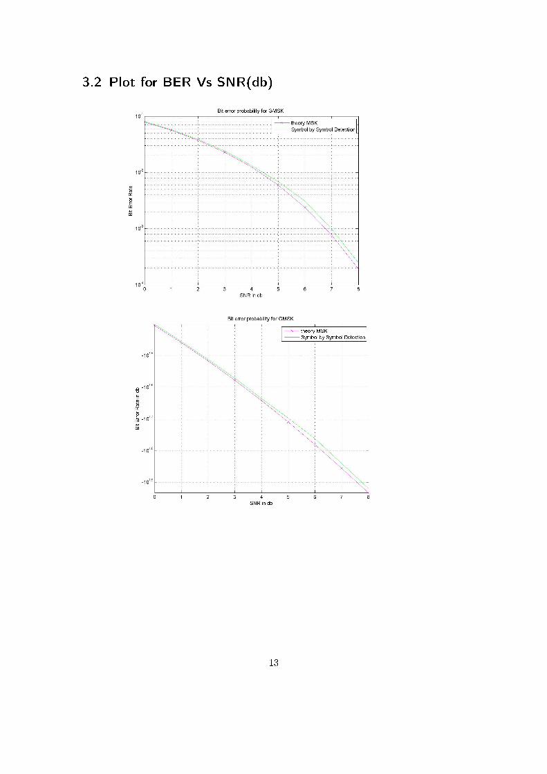
3.2 Plot for BER Vs SNR(db)
13

4 GMSK Demodulator for BT=0.3
For the BT=0.3, g(t) for 3T is plotted in following �gure :
q(t) for 3T is plotted in the following �gure :
If we look at the Gaussian pulse g(t) , we can infer that g(t) is spread out in 3 Symboltime periods. Thus one can expect ISI (Inter Symbol Interference) in the modulation.The Gaussian pre-�lter in GMSK modulation for BT =0.3 introduces intersymbol in-
14

terference (ISI) that spreads over several bit intervals (For BT=0.3, 3 symbols interfere)thus, degrading performance from MSK when coherent symbol-by-symbol detection isused. Maximum likelihood sequence estimation (MLSE) using the Viterbi algorithm iswell known to achieve optimal performance in the presence of ISI. The optimal MLSEdemodulator for GMSK requires 4 ∗ 2L−1 (where L is the ISI duration in bit intervals)states on AWGN channels. The presence of severe multipath fading and narrow-band re-ceive �ltering further increases the number of states making implementation complexityprohibitively high. In this report, MLSE GMSK demodulator that requires 2L−1 statesand achieves almost the same BER performance as MSK. we utilize a linear representa-tion of GMSK signals in terms of basic pulse amplitude modulation (PAM) signals, todesign MLSE demodulator. However, linearized MLSE GMSK demodulator has severaladvantages namely :l ) Usage of a standard o�-the-shelf Viterbi algorithm (VA), that requires 2L+1 addi-
tions for updating state metrics and 2L comparisons to select survivor path, with onesample per bit,2) Because of its linearity, GMSK demodulator can be readily applied to channels with
multipath fading simply by increasing the number of states according to the multipathdelay spread.Initially the symbol by symbol conherent detection was presented in 4.1 and then the
MLSE using the Viterbi algorithm was presented in 4.3.
4.1 Symbol by symbol detection(Without Viterbi)
First , the symbol by symbol detection was done to check the degradation in performancedue to ISI.Using the Laurent PAM representation of the GMSK , BT = 0.3 ,we can write
s(t) =∑
jna0,nh0[t− nT ]The antipodal symbols a0,nare related to transmitted antipodal symbols by the encod-
ing rule a0.n = αna0,n−1 and bn = a0,njn
andr(t) = s(t) + n(t) :
where
SNR = 10 logE(||s(t)||2)E(||n(t)||2)
where s(t) is the transmitted signal, n(t) represents complex additive Gaussian noisewith a one-sided power spectral density of N.Symbol by symbol detection �gure is :
15

4.2 Plot for BER Vs SNR(db) for BT=0.3 without Viterbi.
4.3 MLSE using Viterbi Decoding for BT=0.3
As we can see, the symbol by symbol detection is not performing well because of ISI(Inter-Symbol Interference) caused because of narrowing down the bandwidth. One solution toimprove the performance and remove the ISI(Inter-Symbol Interference) is MLSE(MaximumLikelihood Sequence Estimation) using the Viterbi Algorithm.The demodulator for BT=0.3 using Viterbi Decoding :
16

In baseband, CPM signals can be represented as s(t) = exp(j ∗ ϕ(t, α)), where
ϕ(t, α) = pi ∗ h ∗i=n∑i=0
α[i]q(t− i ∗ T )
. For nT< t < nT + T, we have
s(t) = exp(jpi ∗ hi=n−L∑i=0
α[i])i=n∏
i=n−L+1
exp[j ∗ h ∗ pi ∗ α[i] ∗ q(t− iT )]
In the above case for BT=0.3 , L = 3 .For nT< t < nT + T, we have
s(t) = exp(jpi ∗ hi=n−3∑i=0
α[i])i=n∏i=n−2
exp[j ∗ h ∗ pi ∗ α[i] ∗ q(t− iT )]
s(t) = exp(jpi∗hi=n−3∑i=0
α[i]){exp[j∗h∗pi∗α[i]∗q(t−(n−2)T )]∗exp[j∗h∗pi∗α[i]∗q(t−(n−1)T )]∗exp[j∗h∗pi∗α[i]∗q(t−nT )]}
implies at t=nT ,
s(nT ) = exp(j∗pi∗hi=n−3∑i=0
α[i]){exp[j∗h∗pi∗α[n−2]∗q(2T )]∗exp[j∗h∗pi∗α[n−1]∗q(T )}
So, the state at Sn at t=nT can be represented in terms of (θn, α[n−1], α[n−2]) and thereceived signal can be written as θnbeing the phase accumulatedexp(j∗pi∗h
∑i=n−3i=0 α[i])
r(nT ) = s(nT ) + z(nT )
The optimal MLSE demodulator for GMSK requires 4 ∗ 2L−1 (where L is the ISIduration in bit intervals) states on AWGN channels. 2L−1for previous two symbolsinterfering with current symbol and 4 for the θn.θn can take values of pi/2 or pi or 3 ∗ pi/2 or 0 . Thus for BT=0.3 we need 16 state
viterbi algorithm to optimally estimate the sequence of bits sent through MLSE.The 16 states of the MLSE demodulator can be reduced to 4 by using Laurent Linear
Representation of the transmitted sigmal and demodulating it accordingly as shown inthe demodulator diagram.By using Laurent Linear Representation ,For GMSK with BT=0.3 and L=3, s(t) can be represented by 4 PAM signals
s(t) =3∑
k=0
∑n
jnak,nhk[t− nT ]
h0(t) = C(t− 3T )C(t− 2T )C(t− T ) : 0 ≤ t ≤ 4T
17
h1(t) = C(t− 3T )C(t+ T )C(t− T ) : 0 ≤ t ≤ 2T
h2(t) = C(t− 3T )C(t+ 2T )C(t− 2T ) : 0 ≤ t ≤ Th3(t) = C(t− 3T )C(t+ 2T )C(t+ T ) : 0 ≤ t ≤ T
where
C(t) = sin(pi
2(1− q(t))) : 0 ≤ t ≤ 3T
C(t) = C(−t) : −3T ≤ t ≤ 0
The functions h0(t),h1(t),h2(t),h3(t) are plotted in below �gure :
[1]and it is found that 99.63% of the energy is present in h0(t) . Hence the s(t) =∑3k=0
∑n j
nak,nhk[t− nT ]can be approximated as
s(t) =∑
jna0,nh0[t− nT ]
s(t) =∑
bnh0[t− nT ]
The antipodal symbols a0,nare related to transmitted antipodal symbols by the encod-ing rule a0.n = αna0,n−1 whereαnis the transmitted symbol .Thus the received signal is passed through a matched �lter h∗0[−t] , to get bnand
multiply bnwith j−n to get a0.n.Once a0.n sequence is received, it is passed thorughviterbi decoder to �nd the optimal sequence that was sent.The sequence from the viterbidecoder is di�erentially decoded to give the transmitted symbols αn.
Viterbi Decoder Branch Metric calculations :
Viterbi state transitions can be seen in the following �gure.
18

· · · · · · represent that current symbol is -1 while→ represent that current symbol is +1.and the branch metric calculations branchmetric(n) = ||a(n)− a(n))||2 where a(n) is
the received signal after multiplying bnwith j−n. a(n) can be written as h0a(n)+h1a(n−
1) + h2a(n− 2) since past two symbols are interfering with the current symbol.h0, h1, h2are estimated by using a training sequence of 200 symbols.
4.3.1 Estimating h0, h1, h2:
Estimating h0, h1, h2 is done by sending known symbols. Let us send around 200 symbolswhich are known at the receiver.Let the sent symbols be α(0), α(1), α(2), .......α(198), α(199) and di�erentially encoded
symbols are a(0), a(1), a(2), a(3), .......a(198), a(199). and the received symbols be ˆa(0), ˆa(1), ˆa(2)..... ˆa(198), ˆa(199).Then
ˆa(r) = h0a(r) + h1a(r − 1) + h2a(r − 2) r = 2, 3, ...., 199
which implies that Y = XH where Y =
ˆa(2)ˆa(3)ˆa(4)...ˆa(199)
X =
a(2) a(1) a(0)a(3) a(2) a(1)a(4) a(3) a(2)... ... ...
a(199) a(198) a(197)
H =
h0h1h2
Using LMS Solution , we can �nd H =
(XTX
)−1XTY
Once h0, h1, h2 are estimated , we can calculate the branchmetric as followed:
branchmetric(n) = ||a(n)− {h0a(n) + h1a(n− 1) + h2a(n− 2)}||2
Then MLSE (Maximum Likelihood Sequence Estimation) can be done using StandardViterbi Algorithm.
19

4.4 Plot for BER Vs SNR(db) for BT=0.3 using ViterbiAlgorithm.
20
5 GMSK Demodulation in �at fading
In mobile radio channels, the Rayleigh distribution is commonly used to describe thestatistical time varying nature of the received envelope of a �at fading signal, or theenvelope of an individual multipath component. It's well known that the envelope ofthe sum of two quadrature Gaussian noise signals obeys a Rayleigh distribution. TheRayleigh distribution has a probability density function given by:
p(r) = (r/σ2)exp(−r2/2σ2) (0 < r < inf)
where σ is the rms value of the received voltage signal before envelope detection, and σ2
is the time-average power of the received signal before envelope detection.We can write the received symbol in �at fading channel as
y(n) = h ∗ x(n) + z(n)
z(n) is the AWGN Noise and ||h|| follows rayleigh distribution.
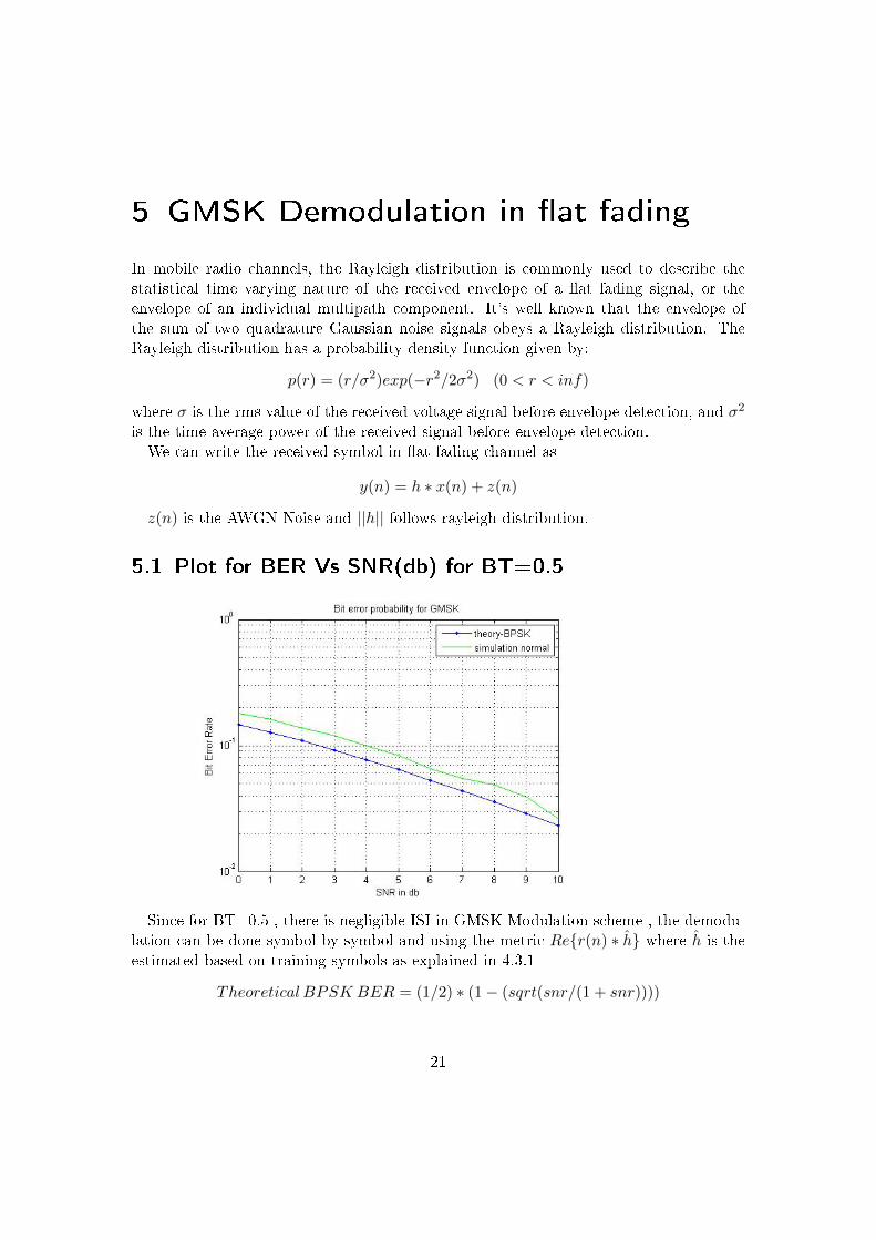
5.1 Plot for BER Vs SNR(db) for BT=0.5
Since for BT=0.5 , there is negligible ISI in GMSK Modulation scheme , the demodu-lation can be done symbol by symbol and using the metric Re{r(n) ∗ h} where h is theestimated based on training symbols as explained in 4.3.1
Theoretical BPSK BER = (1/2) ∗ (1− (sqrt(snr/(1 + snr))))
21

There is degradation of 0.107 db performance from BPSK.
5.2 Plot for BER Vs SNR(db) for BT=0.3 using Viterbi
Since for BT=0.3 , there is ISI in GMSK Modulation scheme , the demodulation canbe done using MLSE.
Theoretical BPSK BER = (1/2) ∗ (1− (sqrt(snr/(1 + snr))))
There is degradation of 0.176 db performance from BPSK on an average for Symbol bySymbol detection without MLSE. But by using MLSE the degradation in performanceis reduced to 0.0485 db.
22
6 GMSK Demodulation in multipathfading
GMSK demodulation for multipath fading of 3 taps is described as below.The received signal y(n) can be written in terms of transmitted signal x(n) as
y(n) = h0x(n) + h1x(n− 1) + h2x(n− 2) + z(n) (6.1)
where ||h0||, ||h1||, ||h2|| follows Raleigh distribution and z(n) is the AWGN.
For BT=0.5 , since there is negligible ISI , 4 state MLSE can be used to estimate thereceived symbols.
For BT=0.3 , since there is ISI , we can further write x(n) = a ∗ s(n) + b ∗ s(n −1) + c ∗ s(n− 2) where s(n), s(n− 1), s(n− 2)are the current and two previous symbolsrespectively.Therefore, one can write y(n) = h0[a ∗ s(n) + b ∗ s(n− 1) + c ∗ s(n− 2)] + h1[a ∗ s(n−1) + b ∗ s(n− 2) + c ∗ s(n− 3)] + h2[a ∗ s(n− 2) + b ∗ s(n− 3) + c ∗ s(n− 4)] + z(n)Thus, 16 state MLSE can be used to estimate the received symbols since the received
signal has components from past 4 symbols.
23
7 Conclusion
In this report, the following things are described :
1. Symbol by symbol detector for BT=0.5 is described and simulated .It is shown thatthere is negligible ISI(Inter Symbol Interference) in this case and the plot for BERVs SNR(in db) was Plotted. It is found that , it performs equally to MSK.
2. Symbol by symbol detector for BT=0.3 is described and simulated .It is shownthat there is ISI(Inter Symbol Interference) in this case. It is shown that past twosymbols interfere with the current symbol.The plot for BER Vs SNR(in db) wasPlotted. It is found that , it doesn't perform equally to MSK due to ISI.
3. 4 state reduced MLSE GMSK demodulator that achieves optimum BER perfor-mance (almost equal to MSK) on AWGN channels is described and simulated.The linear nature of the demodulator allows to use a standard o�-the-shelf Viterbiprocessor.
4. 4-state MLSE GMSK demodulator that acheives optimum BER performance (al-most equal to bpsk) in Rayleigh Fading channel for BT=0.3 was simulated andplots were shown.
24

Nomenclature
GMSK Gaussian Minimum Shift Keying
MSK Minimum Shift Keying
PAM Pulse Amplitude Modulation
DECT Digital Enhanced Cordless Telecommunications
GSM Global System for Mobile Communications
CPM Continous Phase Modulation
CDPD Cellular Digital Packet Data
AWGN Additive White Gaussian Channel
SNR Signal to Noise Ratio
ISI Inter Symbol Interference
BER Bit Error Rate
25

Bibliography
1. N. Al-Dhahir and G. Saulnier ,�A High-Performance Reduced-Complexity GMSKDemodulator�
2. G. David Forney, �Maximum-Likelihood Sequence Estimation of Digital Sequencesin the Presence of Intersymbol Interference�..IEEE Transactions on InformationTheory, 18(3):363-378, May 1972.
3. Ghassan kawas kaleh,�Simple Coherent Receivers for Partial Response Continu-ous Phase Modulation�.IEEE Journal on Selected Areas in Communications, 7(9),December 1989.
4. Kaibin Huang,Supplementary Proof for �Exact and Approximate Construction ofDigital Phase Modulations by Superposition of AMP� by P. A. Laurent.IEEETrans. on Communications, 34(2):150-160, February 1986.
5. Rahnema,�Channel Equalization for the GSM System�
6. G Benelli, G Castellini, R fantacci, Pierucci and Pogliani,�Design of a digital MLSEreceiver for mobile radio communications.�
7. Jen-Wei Liang, Boon C.Ng, Jiunn T.Chen, Arogyaswami Paulraj, �GMSK Lin-earization and structured channel estimate for GSM signals.�
8. J. Anderson, T. Aulin, and C. Sundberg. �Digital Phase Modulation�. Plenum,1986
9. K. Murota, K. Kinoshita, and K. Hirade. �GMSK Modulation for digital mobiletelephony�. IEEE Trans. on Communications, 29:1044-1050, July 1981.
10. R. Steele. �Mobile Radio Communications�. Pentech Press, 1995
26


